MGE model H/I
MGE 71, MGE 80, MGE 90
Service instructions
GRUNDFOS INSTRUCTIONS
2
English (GB) Service instructions
Original service instructions.
CONTENTS
1.
2.
3.
4.
Symbols used in this document
General information
Torques
Secondary materials
5.
6.
Service tools
Megging
7.
Replacing hardware
7.1
Replacing the terminal box cover
7.2
Replacing the battery
7.3
Fitting the antenna
7.4
Replacing the control panel
7.5
Replacing the CIM module
7.6
Replacing the isolation cover
7.7
Replacing the functional module
7.8
Replacing the power module
7.9
Replacing the terminal box
7.10 Replacing the stator housing
7.11 Replacing the fan
7.12 Replacing the bearings
7.13 Replacing IP55 seal rings with IP66 rings
7.14 Configuring the controller
8.
Fault finding
8.1
General information
8.2
Fault indications
8.3
Functional module
8.4
Power module
8.5
Winding resistance
9.
Exploded view
10.
Disposal
Warning
Prior to service work, read these service instructions carefully. Installation and service work must comply with local regulations and accepted codes of good practice.
Observe the safety instructions in the installation and operating instructions for the product.
1. Symbols used in this document
Warning
If these safety instructions are not observed, it may result in personal injury.
Warning
If these instructions are not observed, it may lead to electric shock with consequent risk of serious personal injury or death.
Warning
The surface of the product may be so hot that it may cause burns or personal injury.
Caution
Note
If these safety instructions are not observed, it may result in malfunction or damage to the equipment.
Notes or instructions that make the job easier and ensure safe operation.
Page
5
8
8
7
7
5
6
7
5
5
5
5
8
8
9
10
14
14
15
17
20
23
4
4
25
26
3
3
3
2. General information
These service instructions apply to MGE 71, MGE 80 and
MGE 90, models H and I.
Note
The installation and operating instructions for this product and for the system which it is part of must be available during service of the product.
Position numbers of parts (digits) refer to drawings and parts lists;
position numbers of tools (letters) refer to section 5. Service
tools
.
Electrical parts must only be serviced by Grundfos or an authorised service workshop.
Warning
Use personal protective equipment if there is a risk of getting into contact with the pumped liquid.
Observe local regulations.
Before dismantling
Warning
Switch off the power supply and make sure that it cannot be accidentally switched on. The power supply must be switched off for at least five minutes before you start working on the motor.
Check that other pumps or sources do not force flow through the pump even if the pump is stopped. This will cause the motor to act like a generator, resulting in voltage on the terminals.
• Close the isolating valves, if fitted, and make sure that they cannot be accidentally opened.
• Before starting work on the product, let the product and pumped liquid cool off.
During assembly
• Lubricate and tighten screws and nuts according to
section 3. Torques and 4. Secondary materials.
After assembly
• If analog or digital inputs, the relay output or the CIM module has been removed from the functional module, you must check the communication with external units after service. See
section 7.14 Configuring the controller.
3. Torques
Pos.
152
178
185
192
251d
268
273a
277a
286
288a
289a
291
Designation
Torx screw
Union
Type
Tx25
Tx30
Tx30
Tx30
Tx25
Tx 25
Tx20
Tx20
Tx40
Tx20
Tx30
M20
Dimensions
[mm]
12 x M5
16/10 x 60
16 x M6
14 x 6
50 x M5
12 x M5
32 x M4
32 x M4
21 x M7
M4
14 x 6
M20 x 1.5
* Screws of new terminal boxes must be tightened to 7-8 Nm.
Torque
[Nm]
3.5 — 4
5 — 6*
5 — 6
5 — 6*
5 — 6*
3.5 — 4
1 — 1.3
1 — 1.3
2.2 — 2.7
1 — 1.3
5 — 6
1 — 1.3
3
Torques for terminals
Terminal
L1, L2, L3, L, N
NC, C1, C2, NO
1- 26, A, Y, B
4. Secondary materials
Thread
M4
M2.5
M2
Pos.
156c
159d
159e
Designation
Castrol LMX grease
5. Service tools
Standard tools
A B
Quantity
[kg]
0.1
Max. torque
[Nm]
1.8
0.5
0.5
Product number
00RM4311
C
D
G
J
E
H
K
F
I
L
Pos. Designation For pos.
Further information
Standard tools
A
B
C
Screwdriver
Screwdriver
Screwdriver
Screwdriver
Screwdriver
D
Screwdriver
Ratchet spanner with socket
E Torque screwdriver
F+G Torque wrench
156, 252b Straight slot, 8 mm
273b, 502 Straight slot, 3 mm
273a,
277a, 288a
Torx 20
152, 268,
251d
178, 185,
192, 289a
286
Torx 25
Torx 30
Torx 40
J, K 17 mm
H Bits kit
—
—
152, 178,
185, 251d,
268, 273a,
277a, 286,
287a,
288a, 289a
0.5 — 4 Nm
4-20 Nm
Tx20, Tx25, Tx30,
Tx40
156
—
1300 N
(axial force)
For vice
I
Plastic hammer or press
Soft jaws J
Locking-ring pliers, internal ring
K
L
Locking-ring pliers, external ring
Antistatic service kit
M Bearing heater
Special tools
187
188
—
153, 154
∅50 — 65 (62) mm
∅20 — 30 (25) mm
96884939
N
Punch
Punch
Punch
156c
156c
156c
∅/∅37.8/20.5
98394718
∅/∅44/25.5
98394719
∅/∅60/30.5
98394720
O
Puller
Puller + special arms
153, 154
172
98394731
M
Special tools
N O
4
6. Megging
Caution
An installation with MGE motors must not be megged as this may damage the built-in electronic parts.
Motor windings may, however, be megged if the terminal box has been removed.
Caution
Never measure between two terminals.
1. Disconnect the power supply.
2. Remove the terminal box.
See section 7.9 Replacing the terminal box.
3. Measure between terminals T1, T2, T3 and earth. As windings are star-connected, fault in a winding will show when measuring all terminals.
4. Replace the entire motor unit in case of fault.
See also measurement of winding resistances in section
8.4 Power module
.
5. Fit the terminal box.
See section 7.9 Replacing the terminal box.
6. Switch on the power supply.
7. Start the pump.
Max. test voltage
1000 VAC/1500 VDC
Max. leakage current [mA]
35
7. Replacing hardware
Caution
Always use an antistatic service kit when handling electronic components. This will prevent static electricity from damaging components.
When unprotected, the component must be placed on the antistatic cloth.
Fig. 1
Antistatic service kit
7.1 Replacing the terminal box cover
1. Loosen the four screws (pos. 251d) and remove terminal box cover (pos. 251b).
2. Clean the sealing faces of terminal box (pos. 251a) and the terminal box cover.
3. Fit the terminal box cover and cross-tighten the screws. Make sure that the position of the terminal box cover is correct in relation to the control panel (pos. 290).
Note
The control panel can be turned 180 °.
7.2 Replacing the battery
Applies only to the FM300 functional module.
1. Disconnect the power supply.
2. Remove the terminal box cover. See section 7.1 Replacing
the terminal box cover
.
3. Insert a screwdriver under the battery (pos. 273b) and prise the battery out of the isolation cover (pos. 277).
Caution
The old battery must be disposed off according to the battery directive (2006/66/EC).
Fig. 2
Removing the battery
4. Insert the new battery with the positive pole upwards.
Note
The new battery must comply with the battery directive (2006/66/EC).
5. Press the battery home with a finger.
6. Fit the terminal box cover. See section 7.1 Replacing the
terminal box cover
.
7.3 Fitting the antenna
1. Disconnect the power supply.
2. Remove the terminal box cover.
See section 7.1 Replacing the terminal box cover.
3. Remove blanking plug (pos. 252b) from the terminal box.
4. Fit union (pos. 291) in the terminal box.
5. Lead the antenna into the union from above and tighten the top part (close to the wire).
6. Click the antenna wire onto the control panel (pos. 290).
The antenna wire is long enough to be fitted in both positions of the control panel.
Caution
Make sure that the antenna wire is not sharply bent or pinched when you fit the terminal box cover.
7. Fit the terminal box cover.
See section 7.1 Replacing the terminal box cover.
7.4 Replacing the control panel
1. Disconnect the power supply.
2. Remove the terminal box cover.
See section 7.1 Replacing the terminal box cover.
3. Press and hold in the two locking tabs (fig. 3, pos. A) while gently lifting the control panel (fig. 3, pos. B, and pos. 290).
Fig. 3
Removing the control panel
4. Gently remove the plug for the control panel from functional module (pos. 273).
5. Connect the plug for the new control panel to the functional module.
6. Turn the control panel to the desired position (0 ° / 180 °).
Caution
Do not twist the flat cable by more than 90 °.
5
7. Position the control panel correctly on the four rubber pins
(fig. 4, pos. C). Make sure that the locking tabs (fig. 4, pos. A)
are placed correctly.
8. Fit the new CIM module by aligning it with the plastic holders and the connecting plug. Press home the module using your fingers.
Fig. 4
Fitting the control panel
8. Fit the terminal box cover.
See section 7.1 Replacing the terminal box cover.
7.5 Replacing the CIM module
1. Disconnect the power supply.
2. Remove the terminal box cover.
See section 7.1 Replacing the terminal box cover.
3. Remove the plug connection for the CIM module.
4. Remove the cover (pos. 287) of the CIM module by pressing
the locking tab (fig. 5, pos. A) and lifting the end of the cover
(fig. 5, pos. B). Then lift the cover off the hooks (fig. 5, pos. C).
Fig. 7
Align the CIM module with the connecting plug.
9. Fit the frame screw in the CIM module.
10. Fit the cover by leading the slits into the end with the plug connection and clicking the locking taps onto the isolation cover.
11. Press down the module using your fingers. Check that the plug has been pressed home.
12. CIM 250 and CIM 270: Put the FCC label on the terminal box.
C
A
B
Fig. 5
Removing the cover of the CIM module
5. Remove the screw connecting the frame connection of the
CIM module to the functional module.
6. Insert a screwdriver at the three plastic holders and loosen
the CIM module from isolation cover (pos. 277). See fig. 6.
7. Gently lift the CIM module away from the isolation cover so that the connecting plug is not damaged.
1
3
2
Fig. 8
Position of FCC label
13. Fit the terminal box cover.
See section 7.1 Replacing the terminal box cover.
6
Fig. 6
Removing the CIM module
7.6 Replacing the isolation cover
The example below shows a three-phase motor.
1. Disconnect the power supply.
2. Remove the terminal box cover. See section 7.1 Replacing
the terminal box cover
.
3. Remove control panel (pos. 290) from isolating cover
(pos. 277). See section 7.4 Replacing the control panel.
4. Remove CIM module (pos. 502) from the isolation cover.
See section 7.5 Replacing the CIM module.
5. Pull up/out plug connections (pos. 266) using your fingers.
See fig. 9.
6. Remove screw (pos. 277a) from the isolation cover.
7. You can now remove the isolation cover from the terminal box.
Fig. 9
Removing the plug connections
8. Fit the new isolation cover on the terminal box.
Check that the isolation cover is not clamped.
9. Secure the isolation cover to the terminal box with the screw.
10. Push the plug connection into the relevant terminals. They are marked so that they only fit in the right socket of the functional module.
11. Fit the CIM module.
See section 7.5 Replacing the CIM module.
12. Fit the control panel. See section 7.4 Replacing the control
panel
.
13. Fit the terminal box cover.
See section 7.1 Replacing the terminal box cover.
7.7 Replacing the functional module
1. Disconnect the power supply.
2. Remove the terminal box cover.
See section 7.1 Replacing the terminal box cover.
3. Remove control panel (pos. 290) from isolating cover
(pos. 277). See section 7.4 Replacing the control panel.
4. Remove CIM module (pos. 502) from the isolation cover.
See section 7.5 Replacing the CIM module.
5. Remove isolating cover (pos. 277).
See section 7.6 Replacing the isolation cover.
6. Remove spacer (pos. 286) and screws (pos. 273a).
7. Gently lift the functional module (pos. 273) out of the power module so that the connecting plug (pos. 275a) is not damaged.
8. Pull the connecting plug out of the functional module
(or power module). See fig. 10.
Fig. 10 Removing the connecting plug from the functional
module
9. Insert the connecting plug into the new functional module with the long end towards the module. Lead it through the module and home.
10. Fit the functional module on the power module by means of the five screws. See the order of the screws on the functional module.
11. Fit the spacer on the module.
12. Gently push the connecting plug home.
13. FM300: Put battery in the module.
14. Fit the isolation cover.
See section 7.6 Replacing the isolation cover.
15. Fit the CIM module.
See section 7.5 Replacing the CIM module.
16. Fit the control panel.
See section 7.4 Replacing the control panel.
17. Fit the terminal box cover.
See section 7.1 Replacing the terminal box cover.
18. Calibrate the functional module with the power module.
See section 7.14 Configuring the controller.
7.8 Replacing the power module
If the power module is replaced, the entire bottom of the terminal box must be replaced.
1. Disconnect the power supply.
2. Remove the terminal box cover. See section 7.1 Replacing
the terminal box cover
.
3. Remove control panel (pos. 290) from isolating cover
(pos. 277). See section 7.4 Replacing the control panel.
4. Remove CIM module (pos. 502) from the isolation cover.
See section 7.5 Replacing the CIM module.
5. Remove the isolation cover.
See section 7.6 Replacing the isolation cover.
6. Remove the functional module.
See section 7.7 Replacing the functional module.
7. Pull out plug connection (pos. 266).
8. Remove screws (pos. 178) from terminal box (pos. 251a) and gently lift the terminal box off the motor (pos. 150).
9. Fit the new terminal box on the motor. Make sure that the plug connections are aligned.
10. Cross-tighten the screws of the terminal box.
11. Fit the plug connection for power supply.
12. Fit the functional module.
See section 7.7 Replacing the functional module.
13. Fit the isolation cover.
See section 7.6 Replacing the isolation cover.
14. Fit the CIM module.
See section 7.5 Replacing the CIM module.
15. Fit the control panel.
See section 7.4 Replacing the control panel.
16. Fit the terminal box cover.
See section 7.1 Replacing the terminal box cover.
17. Calibrate the functional module with the power module.
See section 7.14 Configuring the controller.
7
7.9 Replacing the terminal box
1. Disconnect the power supply.
2. Remove the terminal box cover.
See section 7.1 Replacing the terminal box cover.
3. Disconnect all relevant wires.
4. Remove screws (pos. 178) from terminal box (pos. 251a) and gently lift the terminal box off the motor (pos. 150).
5. Fit the new terminal box on the motor. Make sure that the plug connections are aligned.
6. Cross-tighten the screws of the terminal box.
7. Move relevant modules to the new terminal box according to the section above.
8. Connect all relevant wires.
9. Transfer data from the nameplate of the old terminal box to the nameplate of the new one.
Type :
P.N. :
DE :
NDE :
Wgt :
P.C. :
Serial no : kg
Env.Type :
IP :
T amb : o C
CL:
PF:
U in
~ f in
I 1/1 :
:
:
INPUT
V
Hz
A
P2 n max:
Eff
OUTPUT
: kW rpm
:
VARIANT
PB :
FM
HMI
CIM
:
:
:
Made in Hungary
DK — 8850 Bjerringbro, Denmark
7.11 Replacing the fan
1. Disconnect the power supply.
2. Remove the terminal box. See section 7.10 Replacing the
stator housing
.
3. Remove screws (pos. 152) and lift off the fan cover (pos. 151).
4. Insert two screwdrivers close to the shaft and remove the fan
(pos. 156).
Fig. 11 Transferring data to new nameplate
10. Fit the terminal box cover.
See section 7.1 Replacing the terminal box cover.
7.10 Replacing the stator housing
1. Disconnect the power supply.
2. Remove screws (pos. 178) and take terminal box (pos. 251a and 251b) out of stator housing (pos. 150).
Note
Support the terminal box when you remove the motor.
3. Remove the stator housing according the service instructions of the system.
4. Install the stator housing in the system according to the service instructions of the system.
5. Fit the terminal box on the stator housing and cross-tighten the screws.
Fig. 12 Removing the fan
5. Push the fan on the shaft. Alternatively, gently knock the fan onto the shaft (pos. 172) by means of a plastic hammer while holding the drive end of the shaft against a solid surface.
6. Fit the fan cover on stator housing (pos. 150) and tighten screws (pos. 152).
7. Fit the terminal box on the stator housing and cross-tighten the screws.
7.12 Replacing the bearings
1. Disconnect the power supply.
2. Remove the stator housing from the terminal box.
See section 7.10 Replacing the stator housing.
3. Remove the fan. See section 7.11 Replacing the fan.
4. Remove seal rings (pos. 156c) from shaft (pos. 172).
5. Remove screws (pos. 185) holding the flange (pos. 156b).
6. Place the puller on the non-drive end of the stator housing
(pos. 150). See fig. 13.
7. Gently pull the rotor (pos. 172) out of the stator, holding rotor and flange to prevent damage.
Caution
Keep metallic dust away from the rotor as the rotor is magnetic.
8. Remove gasket (pos. 156d) from the flange.
9. Wrap a piece of cardboard or similar material around the magnetic rotor part to protect it against damage and dirt.
10. Put the flange in a vice with soft jaws.
11. Remove bearing (pos. 154) with a puller.
12. MGE 90: Remove locking ring (pos. 187) from the flange.
13. Remove the rotor from the flange and place the rotor in the vice.
Caution
Do not tighten the vice on the bearing journal.
14. MGE 90: Remove locking ring (pos. 188) from the shaft.
15. Remove bearing (pos. 153) with a puller.
Fig. 13 Pushing the rotor out of the stator
8
16. Clean the bearing journal with a clean cloth.
17. Heat the new bearing (pos. 153) to maximum 110 °C.
Caution
Follow the instructions of bearing and bearing heater.
18. Fit the heated bearing (pos. 153) on the shaft (pos. 172).
Warning
Use heat-resistant gloves.
19. MGE 90: Fit locking ring (pos. 188) on the shaft.
20. Place the flange in the vice and clean the bearing seat with a clean cloth.
21. Clean the bearing and fit the rotor in the flange.
22. MGE 90: Fit locking ring (pos. 187) so that the bearing is held by the flange.
23. Clean the bearing journal in the non-drive end with a clean cloth.
24. Heat bearing (pos. 154) to maximum 110 °C.
Caution
Follow the instructions of bearing and bearing heater.
25. Fit the heated bearing (pos. 154) on the shaft (pos. 172).
Warning
Use heat-resistant gloves.
26. Remove the cardboard from the rotor when the bearings have cooled down.
27. Fit the gasket (pos. 156d) on the flange.
28. Check that the corrugated spring water (pos. 158) is correctly fitted in the stator housing.
29. Gently insert the rotor into the stator.
Warning
Watch your fingers when you insert the rotor, as the magnet will pull rotor and stator together with big force.
30. Unscrew the puller to slowly insert the rotor into the stator.
Press flange and stator together when the bearing (pos. 154) has engaged with the stator housing. Check that the drain hole of the flange faces downwards.
31. Remove the puller and cross-tighten screws (pos. 185).
32. Lubricate shafts ends and fit seal rings.
33. Check that the shaft can rotate freely.
34. Fit fan and cover.
See section 7.11 Replacing the fan.
35. Fit the terminal box.
See section 7.10 Replacing the stator housing.
7.13 Replacing IP55 seal rings with IP66 rings
1. Disconnect the power supply.
2. Remove the stator housing from the terminal box.
See section 7.10 Replacing the stator housing.
3. Remove the fan. See section 7.11 Replacing the fan.
4. Remove seal rings (pos. 156c) from shaft (pos. 172).
5. Lubricate gamma ring (pos. 159d) and fit it on the drive end of the shaft.
6. Lift the motor so that the non-drive end of the shaft rests on a solid, vibration-free surface.
7. Gently knock the ring home with the relevant punch.
The distance between flange (pos. 156b) and ring must be 0.8 to 1.3 mm.
Note
The design of the punch ensures correct tolerances.
8. Support the motor so that it rests on the drive end of the shaft.
9. Lubricate gamma ring (pos. 159e) and fit it on the non-drive end of the shaft.
10. Gently knock the ring home with the relevant punch.
The distance between stator housing (pos. 150) and ring must be 0.8 to 1.3 mm.
11. Fit fan and cover.
See section 7.11 Replacing the fan.
12. Fit the terminal box.
See section 7.10 Replacing the stator housing.
9
7.14 Configuring the controller
The terminal box is configured from factory for the intended application and pump type. The configuration file number appears from the terminal box configuration label which is placed inside
the terminal box. See fig. 14.
IR Connect
1. Switch on the power supply to the pump.
2. Connect the MI 301 to the PC.
3. Start the PC Tool. The first time the program is started, the message «No COM port selected» will be shown. Click [OK].
Fig. 14 Position of configuration label
If the terminal box, functional module or power module is replaced or mounted on another motor, it must be reconfigured.
Use PC Tool E-products for that purpose. To establish connection to the motor, use Grundfos GO Remote MI 301 or PC Tool Link.
7.14.1 Connection to motor by means of Grundfos GO
Remote MI 301
Configuration can be done in three ways:
• Radio Scan
• Direct Connect
• IR Connect.
Caution
If the power supply to the pump is interrupted during configuration, the update will be lost.
This will, however, not damage the controller.
Start from the beginning.
Equipment
• PC Tool E-products, version 14.00.00 or newer
• MI 301 (PN 98046408) with USB cable.
Fig. 15 No COM port selected
4. Select «Preferences» in the main menu under «Files».
5. Open the dropdown menu «Select interface» and select
«MI 301». See fig. 16.
Fig. 16 Selecting the user interface
6. Open the dropdown menu «Select port» and select the port
«PCTool-Link». See fig. 16. Click [Apply].
7. Point the MI 301 at the IR eye of the pump.
Distance: max. 20 cm. See fig. 17.
Fig. 17 IR connection via MI 301
8. Click [IR Connect]. See fig. 18. Wait while connection to the
pump is established (10-20 seconds).
Fig. 18 IR Connect
9. To find the GSC file, see section 7.14.3 Configuration with PC
Tool E-products
.
10
Radio Scan
1. Switch on the power supply to the pump.
2. Connect the MI 301 to the PC.
3. Place the MI 301 at a distance of maximum 10 metres from the pump.
4. Start the PC Tool. The first time the program is started, the message «No COM port selected» will be shown. Click [OK].
9. Mark the pump to be connected and click [Connect].
See figures 22 and 23.
Fig. 22 Selection of unit
Fig. 19 No COM port selected
5. Select «Preferences» in the main menu under «Files».
6. Open the dropdown menu «Select interface» and select
«MI 301». See fig. 20.
Fig. 23 Establish connection to the pump
10. Click the button for radio communication. See fig. 24. Status in the PC Tool will change to «Connected». See fig. 25.
Fig. 24 Connection via radio communication
Note
Click [Connect] if the pump is «Unlocked».
See fig. 22.
Fig. 20 Selecting the user interface
7. Open the dropdown menu «Select port» and select the port
«PCTool-Link». See fig. 20. Click [Apply].
8. Click [Radio Scan]. See fig. 21. Wait until connection has
been established to the products the MI 301 can communicate with (10-20 sec.).
Fig. 25 Connection established
11. Find the GSC file for the motor by means of
section 7.14.3 Configuration with PC Tool E-products.
Fig. 21 Radio Scan
11
Direct Connect
1. Switch on the power supply to the pump.
2. Connect the MI 301 to the PC.
3. Place the MI 301 at a distance of maximum 10 metres from the pump.
4. Start the PC Tool. The first time the program is started, the message «No COM port selected» will be shown. Click [OK].
7.14.2 Connection to motor via PC Tool Link
Equipment
• PC Tool E-products, version 14.00.00 or newer
• Grundfos PC Tool Link
• GENIbus cable (RS-485).
Procedure
1. Disconnect the power supply.
2. Remove the terminal box cover.
See section 7.1 Replacing the terminal box cover.
3. Connect PC Tool link to the GENIbus terminals on the motor by means of the GENIbus cable.
Fig. 26 No COM port selected
5. Select «Preferences» in the main menu under «Files».
6. Open the dropdown menu «Select interface» and select
«MI 301». See fig. 27.
A Y B
Fig. 30 Connection of GENIbus
4. Connect the mains supply to the pump.
Fig. 27 Selecting the user interface
7. Open the dropdown menu «Select port» and select the port
«PCTool-Link». See fig. 27. Click [Apply].
8. Click [Direct Connect]. See fig. 28. Wait until connection has
been established to the products the MI 301 can communicate with (10-20 sec.).
Fig. 28 Direct Connect
9. Click the motor button for radio communication.
Connection has now been established.
Fig. 29 Connection via radio communication
10. Find the GSC file for the motor by means of
section 7.14.3 Configuration with PC Tool E-products.
12
7.14.3 Configuration with PC Tool E-products
Find the desired configuration file in PC Tool E-products in this way:
1. Start the PC Tool.
2. Find the desired configuration file in PC Tool E-products in one of these ways:
• Search by the configuration number. See fig. 31.
• Search on the basis of the application that MGE is part of.
• Choose the file position on the PC hard disk via the PC Tool
E-products browser.
Searching by configuration number
2
3
1. Select «Standard configuration».
2. Select «Number».
4
1
Fig. 31 Configuration of terminal box by searching by the GSC number
3. End the PC Tool and remove the MI 301.
6
5
3. Enter a number or part of a number.
4. Click [Search now].
5. Select the configuration file in the list of search results.
6. Click [Send] to download the configuration file to the MGE.
13
8. Fault finding
8.1 General information
1. Check the mains supply to the pump.
2. Read fault messages by means of Grundfos Eye,
Grundfos GO Remote, PC Tool or R100.
Note
Make a copy of motor settings.
3. If possible, test if the motor can run without load. Remove the coupling to the pump (if possible) and set the operating signal to max. by means of PC Tool, Grundfos GO Remote or R100.
You can reset a fault indication in the following ways:
• When the fault cause has been eliminated and the pump is switched on, the pump will revert to normal duty.
• If the fault disappears by itself, the fault indication will automatically be reset.
The fault cause will be stored in the pump alarm or warning log.
Fault indications via Grundfos Eye
See the indication of motor status by means of the Grundfos Eye and the contact positions of signal relays in the installation and operating instructions for the MGE motor.
Fault indications via Grundfos GO Remote
See the description of the Grundfos GO Remote control panel and possibilities of communication in the installation and operating instructions for the MGE motor.
Fig. 33 Alarm and warning log of the MI 201
For a detailed description the fault, see display «Assisted fault advice».
Fig. 32 Alarms and warnings shown on the MI 201
Fig. 34 Detailed fault description
Fault indications via R100
Note
The R100 must be updated to be used for
MGE 71, MGE 80 and MGE 90, model H/I.
See the description of the R100 display and possibilities of communication in the installation and operating instructions for the MGE motor.
14
8.2 Fault indications
The fault indication below can be read by means of the number in brackets, as text or as status indications on the control panel, depending on the equipment available.
Grundfos Eye Condition/cause Remedy
Two opposite red indicator lights flashing simultaneously.
External fault (3)
An external signal has reported an
«External fault» to the digital input set up for this function.
Too many restarts (4)
Check the parameter or the unit reporting the external fault. Correct the fault.
The pump has restarted to many times in connection with a fault that forced the pump to stop and restart automatically.
a) Check the warning and alarm log for faults that caused to many restarts.
b) Replace the pump if the fault cannot be found.
Overvoltage (32)
Supply voltage to the pump too high.
a) Check that the power supply is within the specified range.
Undervoltage (40)
Supply voltage to the pump too low.
a) Check that the power supply is within the specified range.
Overload (49)
The motor is overloaded and has automatically reduced the speed and thus the pump performance.
a) Check that the viscosity and temperature of the pump liquid is within the limits for the pump.
If not, change the properties of the liquid.
b) Dismantle the pump, and remove any foreign matter or impurities preventing the pump from rotating.
c) If none of the above causes are present, replace the pump.
Blocked pump (51)
The pump is blocked.
a) Dismantle the pump, and remove any foreign matter or impurities preventing the pump from rotating.
Pump communication fault (10)
Communication fault between this pump and the other pumps of the multipump system.
One yellow indicator light permanently on.
Forced pumping (29)
a) Check that all pumps of the multipump system have been correctly set up.
Other pumps or sources force flow through the pump even if the pump is stopped.
a) Check the system for defective non-return valves and replace, if necessary. Check the system for correct position of non-return valves, etc.
Dry running (56, 57)
No water at the pump inlet or the water contains too much air.
a) Prime and vent the pump before a new start-up.
Check that the pump is operating correctly.
If not, replace the pump.
Internal fault (72, 83, 85, 155, 157, 163)
Internal fault in the pump electronics.
a) Replace the functional module, power module or terminal box.
One yellow indicator light permanently on.
High motor temperature (65, 66)
1. The motor temperature is too high.
a) Check that the ambient temperature is within the specified range.
b) Check that the pump is not covered by dust, dirt or other foreign matter which reduces the air cooling of the pump.
c) If none of the above causes are present, replace the motor.
Internal communication fault (76)
1. Communication fault between different parts of the electronics.
a) Replace the terminal box.
Soft pressure buildup, timeout (215)
1. The system has been in the mode
«soft pressure buildup» longer than the set time limit.
a) Check the system for leakages.
15
Grundfos Eye
One yellow indicator light rotating in the direction of rotation of the motor when seen from the non-drive end.
Condition/cause Remedy
Replace motor bearings (30)
1. The bearings must be replaced.
a) Follow the instructions for the pump.
See section 7.12 Replacing the bearings.
Internal sensor fault (88)
1. The pump is receiving a signal from the internal sensor which is outside the normal range.
a) Check that the plug and cable are connected correctly to the sensor. The sensor is on the back of the pump housing.
b) Replace the sensor.
Pt100/1000 sensor 1 (91) and 2 (175)
1. Pt100/1000 input 1 is receiving a signal which is outside the normal range.
Supply fault, 24 V (162)
1. Fault in the output voltage.
a) Check that the sensor resistance corresponds to
≈ 100 or 1000 ohm. If not, replace the sensor.
b) Check the sensor cable for damage.
c) Check the cable connection at the pump and at the sensor. Correct the connection, if required.
d) Replace the sensor.
Supply fault, 5 V (161)
1. Fault in the output voltage to sensor or potentiometer.
a) Check the output voltage and wire to sensor or potentiometer.
a) Check the output voltage and wire.
Signal fault, LiqTec-sensor (164)
1. The pump is receiving a signal from the LiqTec sensor which is outside the normal range.
a) Check that the plug and cable are connected correctly to the sensor.
b) Replace the sensor.
Signal fault, sensor 1 (165), 2 (166) and 3 (167)
1. Analog input 1, 2 or 3 is receiving a signal which is outside the normal range.
a) Check the setup of the analog input corresponds to the sensor output as regards electrical
(0.5 — 3.5 V, 0-5 V, 0-10 V, 0-20 mA or 4-20 mA).
If not, change the setting, or replace the sensor with one that matches the setup.
b) Check the sensor cable for damage.
c) Check the cable connection at the pump and at the sensor. Correct the connection, if required.
d) Check if the sensor has been removed, but the input was not deactivated.
e) Replace the sensor.
Limit 1 exceeded (190) and limit 2 exceeded (191)
1. Limit 1 or 2 has reached the limit for warning/alarm.
a) Identify and remove the fault cause.
16
8.3 Functional module
Warning
The terminals of the power module are live.
Relay RL1 may also be live.
Warning
Measuring equipment must be free of static electricity or have same potential as the motor before being used for measurement without isolation cover.
1. The status diode of the functional module flashes
40-80 times/minute when the software is running correctly.
See fig. 35. The functional module can only function if the
power module is in operation, as the power module supplies voltage to the functional module.
See section 8.3 Functional module.
Status
Permanently on.
Light off.
Flashing
40-80 times/minute.
Fault
The microprocessor is frozen.
The functional module is defective.
See section 7.7.
The functional module is defective.
See section 7.7.
The processor of the functional module is functional.
Fig. 35 Status diode of functional module
2. If the light diode is flashing, the functional module is working correctly. The fault may then be in the control panel.
See section 7.4 Replacing the control panel.
17
3. If the status diode of the functional module is off, check if the power module supplies voltage by measuring 8.5 VDC on the
VFE plug connection between functional module and power module. If no voltage is measured, the connection between the modules or the power module is defective.
If the VFE voltage to the functional module is okay, check if the voltage between the reference point and the other measuring points is okay. The voltage values apply to an operating motor.
1 ref.
2
3
4
Fig. 36 Measuring voltage on the functional module
Note
Use a correctly calibrated measuring instrument.
Control voltage [VDC]
Pos.
Minimum Nominal Maximum
VFE
(J15)
1
2
5
6
3
4 ref.
14.5
4.8
4.8
3.2
23
4.8
8.5
15.1
5
5
3.3
23.9
5
GND
15.7
5.2
5.2
3.4
24.8
5.2
Replace the functional module if the voltage is not correct.
See section 7.7 Replacing the functional module.
5
6
6
5
VFE
18
8.3.1 Checking input and outputs
Note
Make a copy of motor settings.
Pt100/1000
Use a 100 Ω resistance and decide on the basis on the motor settings which value this resistance will show in the display when connected to the terminals instead of the Pt100/1000 sensor.
Analog input, AI
It is possible to measure on the analog input to determine if its function is correct.
During current state, a 292 Ω resistance in the input converts a current signal (e.g. 0-20 mA) from the sensor to a voltage signal for the processor.
Measure the voltage across the input and read the current in the circuit by means of Grundfos GO Remote or PC Tool. The current value must be equal to voltage divided with resistance.
Alternatively, a milliammeter can be connected in series with the circuit.
P
V
Digital input, DI
See the settings of the input in PC Tool.
Connect the digital input to frame (GND) by means of an ammeter. The value measured must now be approximately
12 mA. Check that PC Tool shows a corresponding value.
DI
A 12 mA
GND
Fig. 40 Testing the digital input
Digital output, DO/open collector, OC
See the settings of the output in PC Tool.
Measure on the output. If the value in PC Tool differs from the value measured with the measuring instrument, remove the load.
If the values still differ, the module is defective.
The voltage of an active output is approx. 5 V.
DO
Fig. 38 Testing the input during voltage state
Change the setup of the input to current state and measure on the input using an ohmmeter. The resistance must be 292 Ω.
In voltage state the resistance will be 122 kΩ.
ȍ
Fig. 39 Measuring resistance in current and voltage state
Analog output, AO
The analog input is protected against short-circuit and will shut down the signal in case of short-circuit. If you suspect a short-circuit, remove the load and compare the value read via
PC Tool with the value measured by means of the measuring instrument.
If the values are not identical, the module is defective.
V
0-5 V
A
Fig. 37 Measuring on analog input
Next step is to test the input in voltage state. Change the setup of the input to voltage state (0-10 V). Fit a jumper between terminal
5 (+5 V) and the analog input. 5 V must now be read be means of
PC Tool.
+ 5 V AI
GND
Fig. 41 Measuring voltage on the digital output
LiqTec sensor
Connect a new LiqTec sensor to check the input. Immerse the sensor into water and take it up. The motor must now report fault within 20 seconds.
Signal relay
See the settings of the output in PC Tool.
Check if the relay reacts to the signals of the controller according to the configuration of the controller.
CIM
Test the CIM module according to its manual.
Radio
If there are problems in the radio connection between
Grundfos GO Remote and the motor, remove the terminal box
cover. See section 7.1 Replacing the terminal box cover.
Replace the control panel if there is still no connection.
See section 7.4 Replacing the control panel.
Battery
Make the motor dead for a short period. When you switch on the power to the pump again, the clock must show correct time in relation to how long it was dead.
Control panel (HMI)
Check the flat cable to the functional module. Replace the control panel if the connection is correct, and it did not solve the problem.
19
8.4 Power module
Warning
The terminals of the power module are live.
Warning
Measuring equipment must be free of static electricity or have same potential as the motor before being used for measurement without isolation cover.
If reading of fault codes does not provide a clear answer as to whether the power module is functioning correctly, you can proceed as described below.
1. Check that the voltage to the module is within the limit values stated on the nameplate. Check all phases of a three-phase motor.
2. If there are signs of moisture in the terminal box, take necessary precautions to prevent similar faults.
3. Check the two status diodes of the power module
(the functional module must be connected) by looking under the power module from the side. Status diode D54 must be permanently on when connected to mains. Status diode D7
(three-phase model) or D19 (single-phase model) flashes when the functionality is correct. See table below.
Note
It may be necessary to dim the light as the diode light is weak.
Status, single-phase
D19 is permanently on.
Fault
• The microprocessor is frozen.
• No initialising message from the functional module.
Switch the power supply off and on. If this does not solve the problem, replace the power
module. See section 7.8.
The power module is defective.
See section 7.8.
D19 is off.
D19 is flashing
40-80 times/minute, and
D54 is permanently on.
D54 is off.
The power module is functional.
D19 and D54 are flashing
40-80 times/minute.
The power module is defective.
See section 7.8.
Short-circuit in the connection to the functional module or in the functional module.
Status, three-phase
D7 is permanently on.
D7 is off.
D7 is flashing
40-80 times/minute.
D54 is permanently on.
D54 is off.
Fault
• The microprocessor is frozen.
• No initialising message from the functional module.
Switch the power supply off and on. If this does not solve the problem, replace the power
module. See section 7.8.
The power module is defective.
See section 7.8.
The processor of the power module is functional.
The processor of the power module is functional.
The power module is defective.
See section 7.8.
LED D7 Micro Controller LED D54 5V
Fig. 43 Status diodes of power module, three-phase
20
LED D19 Micro Controller LED D54 5V
Fig. 42 Status diode of power module, single-phase
4. The DC voltage across the capacitor of the intermediate circuit on the single-phase power module can be measured to make sure that the capacitor is not short-circuited. If the function is correct, the voltage must be
≥ 350 V (at a mains
voltage of 230 V). See fig. 44. If not, the module is defective.
Fig. 44 Measuring the DC voltage on single-phase power board
_
+
21
5. The DC voltage across the capacitors of the intermediate circuit on the three-phase power module can be measured to make sure that the capacitors are not short-circuited. If the function is correct, the voltage must be
≥ 566 V (at a mains
voltage of 400 V). See fig. 45. If not, the module is defective.
GND
DC+
Fig. 45 Measuring the DC voltage on three-phase power board
GND DC+
22
8.5 Winding resistance
As the motor is star-connected, the easiest way to measure the winding resistance is to measure across two phases. Measure at the coil temperatures stated in the table below. It may be necessary to let the motor cool off if it has been running or if it was stopped because of short-circuit or overload.
Motor Min
-1
Type
Voltage [VAC]
1 x 200-240
1500-2000
3 x 380-500
MGE 71, MLE 71
MGE 80, MLE 80
MGE 90, MLE 90
3000-4000
4000-5900
1500-2000
3000-4000
4000-5900
1500-2000
3000-4000
4000-5900
1 x 200-240
3 x 380-500
1 x 200-240
3 x 380-500
1 x 200-240
3 x 380-500
1 x 200-240
3 x 380-500
1 x 200-240
3 x 380-500
3 x 380-500
1 x 200-240
3 x 380-500
1 x 200-240
3 x 380-500
Power [kW/hp]
0.25 / 0.33
0.37 / 0.5
0.55 / 0.75
0.55 / 0.75
0.75 / 1
0.55 / 0.75
0.75 / 1
0.75 / 1
1.1 / 1.5
0.75 / 1
1.1 / 1.5
0.75 / 1
1.1 / 1.5
0.75 / 1
1.1 / 1.5
0.25 / 0.33
0.37 / 0.5
0.25 / 0.33
0.37 / 0.5
0.25 / 0.33
0.37 / 0.5
0.55 / 0.75
0.25 / 0.33
0.37 / 0.5
0.55 / 0.75
0.25 / 0.33
0.37 / 0.5
0.55 / 0.75
1.1 / 1.5
1.5 / 2
1.5 / 2
2.2 / 3
1.5 / 2
1.5 / 2
2.2 / 3
Min. / max. resistance across two phases
[Ω]
20 °C
4.6 / 5.4
4.6 / 5.4
4.6 / 5.4
6.9 / 8.1
4.3 / 5.1
21.2 / 24.8
13.5 / 15.9
1.5 / 1.7
1.6 / 1.8
4.6 / 5.4
5.3 / 6.3
1.5 / 1.7
1.5 / 1.7
4.6 / 5.4
4.6 / 5.4
12 / 14
12 / 14
40.5 / 47.5
40.5 / 47.5
3 / 3.6
3 / 3.6
3 / 3.6
10.4 / 12.2
10.4 / 12.2
10.4 / 12.2
1.5 / 1.7
1.5 / 1.7
1.5 / 1.7
8.9 / 10.5
1.1 / 1.3
3.8 / 4.4
2.2 / 2.6
0.8 / 1
2.4 / 2.8
1.6 / 1.8
60 °C
5.3 / 6.2
5.3 / 6.2
5.3 / 6.2
8 / 9.4
5 / 5.9
24.5 / 28.7
15.6 / 18.4
1.7 / 2
1.8 / 2.1
5.3 / 6.2
6.2 / 7.2
1.7 / 2
1.7 / 2
5.3 / 6.2
5.3 / 6.2
13.8 / 16.2
13.8 / 16.2
46.8 / 55
46.8 / 55
3.5 / 4.1
3.5 / 4.1
3.5 / 4.1
12 / 14.1
12 / 14.1
12 / 14.1
1.7 / 2
1.7 / 2
1.7 / 2
10.3 / 12.1
1.3 / 1.5
4.4 / 5.1
2.6 / 3
1 / 1.1
2.8 / 3.2
1.8 / 2.1
80 °C
5.7 / 6.7
5.7 / 6.7
5.7 / 6.7
8.5 / 10
5.3 / 6.3
26.1 / 30.7
16.7 / 19.6
1.8 / 2.1
1.9 / 2.3
5.7 / 6.7
6.6 / 7.7
1.8 / 2.1
1.8 / 2.1
5.7 / 6.7
5.7 / 6.7
14.8 / 17.3
14.8 / 17.3
50 / 58.7
50 / 58.7
3.8 / 4.4
3.8 / 4.4
3.8 / 4.4
12.8 / 15.1
12.8 / 15.1
12.8 / 15.1
1.8 / 2.1
1.8 / 2.1
1.8 / 2.1
11 / 12.9
1.4 / 1.6
4.7 / 5.5
2.7 / 3.2
1 / 1.2
3 / 3.5
1.9 / 2.3
23
Measure between terminals T1 and T2, and between T2 and T3.
Terminal
T1, T2, T3
Description
Input for the three phases
Fig. 46 Motor terminals
T1 T2
T3
Fig. 47 Wiring diagram
~
24
9. Exploded view
Fig. 48 MGE 90
25
10. Disposal
This product or parts of it must be disposed of in an environmentally sound way:
1. Use the public or private waste collection service.
2. If this is not possible, contact the nearest Grundfos company or service workshop.
Subject to alterations.
26
Argentina
Bombas GRUNDFOS de Argentina S.A.
Ruta Panamericana km. 37.500 Centro
Industrial Garin
1619 Garín Pcia. de B.A.
Phone: +54-3327 414 444
Telefax: +54-3327 45 3190
Australia
GRUNDFOS Pumps Pty. Ltd.
P.O. Box 2040
Regency Park
South Australia 5942
Phone: +61-8-8461-4611
Telefax: +61-8-8340 0155
Austria
GRUNDFOS Pumpen Vertrieb Ges.m.b.H.
Grundfosstraße 2
A-5082 Grödig/Salzburg
Tel.: +43-6246-883-0
Telefax: +43-6246-883-30
Belgium
N.V. GRUNDFOS Bellux S.A.
Boomsesteenweg 81-83
B-2630 Aartselaar
Tél.: +32-3-870 7300
Télécopie: +32-3-870 7301
Belarus
Представительство ГРУНДФОС в
Минске
220125, Минск ул. Шафарнянская, 11, оф. 56
Тел.: +7 (375 17) 286 39 72, 286 39 73
Факс: +7 (375 17) 286 39 71
E-mail: [email protected]
Bosnia/Herzegovina
GRUNDFOS Sarajevo
Trg Heroja 16,
BiH-71000 Sarajevo
Phone: +387 33 713 290
Telefax: +387 33 659 079 e-mail: [email protected]
Brazil
BOMBAS GRUNDFOS DO BRASIL
Av. Humberto de Alencar Castelo Branco,
630
CEP 09850 — 300
São Bernardo do Campo — SP
Phone: +55-11 4393 5533
Telefax: +55-11 4343 5015
Bulgaria
Grundfos Bulgaria EOOD
Slatina District
Iztochna Tangenta street no. 100
BG — 1592 Sofia
Tel. +359 2 49 22 200
Fax. +359 2 49 22 201 email: [email protected]
Canada
GRUNDFOS Canada Inc.
2941 Brighton Road
Oakville, Ontario
L6H 6C9
Phone: +1-905 829 9533
Telefax: +1-905 829 9512
China
GRUNDFOS Pumps (Shanghai) Co. Ltd.
50/F Maxdo Center No. 8 XingYi Rd.
Hongqiao development Zone
Shanghai 200336
PRC
Phone: +86 21 612 252 22
Telefax: +86 21 612 253 33
Croatia
GRUNDFOS CROATIA d.o.o.
Cebini 37, Buzin
HR-10010 Zagreb
Phone: +385 1 6595 400
Telefax: +385 1 6595 499 www.grundfos.hr
Czech Republic
GRUNDFOS s.r.o.
Čajkovského 21
779 00 Olomouc
Phone: +420-585-716 111
Telefax: +420-585-716 299
Denmark
GRUNDFOS DK A/S
Martin Bachs Vej 3
DK-8850 Bjerringbro
Tlf.: +45-87 50 50 50
Telefax: +45-87 50 51 51
E-mail: [email protected]
www.grundfos.com/DK
Estonia
GRUNDFOS Pumps Eesti OÜ
Peterburi tee 92G
11415 Tallinn
Tel: + 372 606 1690
Fax: + 372 606 1691
Finland
OY GRUNDFOS Pumput AB
Mestarintie 11
FIN-01730 Vantaa
Phone: +358-(0)207 889 900
Telefax: +358-(0)207 889 550
France
Pompes GRUNDFOS Distribution S.A.
Parc d’Activités de Chesnes
57, rue de Malacombe
F-38290 St. Quentin Fallavier (Lyon)
Tél.: +33-4 74 82 15 15
Télécopie: +33-4 74 94 10 51
Germany
GRUNDFOS GMBH
Schlüterstr. 33
40699 Erkrath
Tel.: +49-(0) 211 929 69-0
Telefax: +49-(0) 211 929 69-3799 e-mail: [email protected]
Service in Deutschland: e-mail: [email protected]
HILGE GmbH & Co. KG
Hilgestrasse 37-47
55292 Bodenheim/Rhein
Germany
Tel.: +49 6135 75-0
Telefax: +49 6135 1737 e-mail: [email protected]
Greece
GRUNDFOS Hellas A.E.B.E.
20th km. Athinon-Markopoulou Av.
P.O. Box 71
GR-19002 Peania
Phone: +0030-210-66 83 400
Telefax: +0030-210-66 46 273
Hong Kong
GRUNDFOS Pumps (Hong Kong) Ltd.
Unit 1, Ground floor
Siu Wai Industrial Centre
29-33 Wing Hong Street &
68 King Lam Street, Cheung Sha Wan
Kowloon
Phone: +852-27861706 / 27861741
Telefax: +852-27858664
Hungary
GRUNDFOS Hungária Kft.
Park u. 8
H-2045 Törökbálint,
Phone: +36-23 511 110
Telefax: +36-23 511 111
India
GRUNDFOS Pumps India Private Limited
118 Old Mahabalipuram Road
Thoraipakkam
Chennai 600 096
Phone: +91-44 2496 6800
Indonesia
PT GRUNDFOS Pompa
Jl. Rawa Sumur III, Blok III / CC-1
Kawasan Industri, Pulogadung
Jakarta 13930
Phone: +62-21-460 6909
Telefax: +62-21-460 6910 / 460 6901
Ireland
GRUNDFOS (Ireland) Ltd.
Unit A, Merrywell Business Park
Ballymount Road Lower
Dublin 12
Phone: +353-1-4089 800
Telefax: +353-1-4089 830
Italy
GRUNDFOS Pompe Italia S.r.l.
Via Gran Sasso 4
I-20060 Truccazzano (Milano)
Tel.: +39-02-95838112
Telefax: +39-02-95309290 / 95838461
Japan
GRUNDFOS Pumps K.K.
Gotanda Metalion Bldg., 5F,
5-21-15, Higashi-gotanda
Shiagawa-ku, Tokyo
141-0022 Japan
Phone: +81 35 448 1391
Telefax: +81 35 448 9619
Korea
GRUNDFOS Pumps Korea Ltd.
6th Floor, Aju Building 679-5
Yeoksam-dong, Kangnam-ku, 135-916
Seoul, Korea
Phone: +82-2-5317 600
Telefax: +82-2-5633 725
Latvia
SIA GRUNDFOS Pumps Latvia
Deglava biznesa centrs
Augusta Deglava ielā 60, LV-1035, Rīga,
Tālr.: + 371 714 9640, 7 149 641
Fakss: + 371 914 9646
Lithuania
GRUNDFOS Pumps UAB
Smolensko g. 6
LT-03201 Vilnius
Tel: + 370 52 395 430
Fax: + 370 52 395 431
Malaysia
GRUNDFOS Pumps Sdn. Bhd.
7 Jalan Peguam U1/25
Glenmarie Industrial Park
40150 Shah Alam
Selangor
Phone: +60-3-5569 2922
Telefax: +60-3-5569 2866
Mexico
Bombas GRUNDFOS de México S.A. de
C.V.
Boulevard TLC No. 15
Parque Industrial Stiva Aeropuerto
Apodaca, N.L. 66600
Phone: +52-81-8144 4000
Telefax: +52-81-8144 4010
Netherlands
GRUNDFOS Netherlands
Veluwezoom 35
1326 AE Almere
Postbus 22015
1302 CA ALMERE
Tel.: +31-88-478 6336
Telefax: +31-88-478 6332
E-mail: [email protected]
New Zealand
GRUNDFOS Pumps NZ Ltd.
17 Beatrice Tinsley Crescent
North Harbour Industrial Estate
Albany, Auckland
Phone: +64-9-415 3240
Telefax: +64-9-415 3250
Norway
GRUNDFOS Pumper A/S
Strømsveien 344
Postboks 235, Leirdal
N-1011 Oslo
Tlf.: +47-22 90 47 00
Telefax: +47-22 32 21 50
Poland
GRUNDFOS Pompy Sp. z o.o.
ul. Klonowa 23
Baranowo k. Poznania
PL-62-081 Przeźmierowo
Tel: (+48-61) 650 13 00
Fax: (+48-61) 650 13 50
Portugal
Bombas GRUNDFOS Portugal, S.A.
Rua Calvet de Magalhães, 241
Apartado 1079
P-2770-153 Paço de Arcos
Tel.: +351-21-440 76 00
Telefax: +351-21-440 76 90
Romania
GRUNDFOS Pompe România SRL
Bd. Biruintei, nr 103
Pantelimon county Ilfov
Phone: +40 21 200 4100
Telefax: +40 21 200 4101
E-mail: [email protected]
Russia
ООО Грундфос
Россия, 109544 Москва, ул. Школьная
39
Тел. (+7) 495 737 30 00, 564 88 00
Факс (+7) 495 737 75 36, 564 88 11
E-mail [email protected]
Serbia
GRUNDFOS Predstavništvo Beograd
Dr. Milutina Ivkovića 2a/29
YU-11000 Beograd
Phone: +381 11 26 47 877 / 11 26 47 496
Telefax: +381 11 26 48 340
Singapore
GRUNDFOS (Singapore) Pte. Ltd.
25 Jalan Tukang
Singapore 619264
Phone: +65-6681 9688
Telefax: +65-6681 9689
Slovenia
GRUNDFOS d.o.o.
Šlandrova 8b, SI-1231 Ljubljana-Črnuče
Phone: +386 1 568 0610
Telefax: +386 1 568 0619
E-mail: [email protected]
South Africa
GRUNDFOS (PTY) LTD
Corner Mountjoy and George Allen Roads
Wilbart Ext. 2
Bedfordview 2008
Phone: (+27) 11 579 4800
Fax: (+27) 11 455 6066
E-mail: [email protected]
Spain
Bombas GRUNDFOS España S.A.
Camino de la Fuentecilla, s/n
E-28110 Algete (Madrid)
Tel.: +34-91-848 8800
Telefax: +34-91-628 0465
Sweden
GRUNDFOS AB
Box 333 (Lunnagårdsgatan 6)
431 24 Mölndal
Tel.: +46 31 332 23 000
Telefax: +46 31 331 94 60
Switzerland
GRUNDFOS Pumpen AG
Bruggacherstrasse 10
CH-8117 Fällanden/ZH
Tel.: +41-1-806 8111
Telefax: +41-1-806 8115
Taiwan
GRUNDFOS Pumps (Taiwan) Ltd.
7 Floor, 219 Min-Chuan Road
Taichung, Taiwan, R.O.C.
Phone: +886-4-2305 0868
Telefax: +886-4-2305 0878
Thailand
GRUNDFOS (Thailand) Ltd.
92 Chaloem Phrakiat Rama 9 Road,
Dokmai, Pravej, Bangkok 10250
Phone: +66-2-725 8999
Telefax: +66-2-725 8998
Turkey
GRUNDFOS POMPA San. ve Tic. Ltd. Sti.
Gebze Organize Sanayi Bölgesi
Ihsan dede Caddesi,
2. yol 200. Sokak No. 204
41490 Gebze/ Kocaeli
Phone: +90 — 262-679 7979
Telefax: +90 — 262-679 7905
E-mail: [email protected]
Ukraine
ТОВ ГРУНДФОС УКРАЇНА
01010 Київ, Вул. Московська 8б,
Тел.:(+38 044) 390 40 50
Фах.: (+38 044) 390 40 59
E-mail: [email protected]
United Arab Emirates
GRUNDFOS Gulf Distribution
P.O. Box 16768
Jebel Ali Free Zone
Dubai
Phone: +971 4 8815 166
Telefax: +971 4 8815 136
United Kingdom
GRUNDFOS Pumps Ltd.
Grovebury Road
Leighton Buzzard/Beds. LU7 4TL
Phone: +44-1525-850000
Telefax: +44-1525-850011
U.S.A.
GRUNDFOS Pumps Corporation
17100 West 118th Terrace
Olathe, Kansas 66061
Phone: +1-913-227-3400
Telefax: +1-913-227-3500
Uzbekistan
Grundfos Tashkent, Uzbekistan The Representative Office of Grundfos Kazakhstan in
Uzbekistan
38a, Oybek street, Tashkent
Телефон: (+998) 71 150 3290 / 71 150
3291
Факс: (+998) 71 150 3292
Addresses Revised 06.05.2013
98413121
0513
ECM: 1106756 www.grundfos.com
Перейти к контенту
-
Bookmarks
Quick Links
GRUNDFOS INSTRUCTIONS
MGE
Antenna
Service kit instructions
Related Manuals for Grundfos MGE Series
Summary of Contents for Grundfos MGE Series
-
Page 1
GRUNDFOS INSTRUCTIONS Antenna Service kit instructions… -
Page 3
English (GB) Service kit instructions CONTENTS Page 1. Dismantling 2. Assembly English (GB) Warning Before starting service work, read the safety instructions supplied with the product. Always use an antistatic service kit when handling electronic components. This will prevent static electricity from damaging components. -
Page 4
Deutsch (DE) Warnung Vor der Durchführung irgendwelcher Reparaturarbeiten ist die mit dem Produkt mitgelieferte Serviceanleitung sorgfältig durchzulesen. Bei m Umgang mit elektronischen Bauteilen ist immer ein antistatischer Erdungsreparatursatz zu verwenden. Dadurch wird verhindert, dass die Bauteile durch statische Entladung beschädigt werden. Siehe nachfolgende Abbil- Caution dung. -
Page 5
Français (FR) Avertissement Avant toute intervention, consulter les consignes de mainte- nance fournies avec le produit. Toujours utiliser un kit de maintenance antistatique lors de la manipulation de composants électroniques. Cela évite que l’électricité statique n’endommage les composants. Caution Voir figure ci-dessous. Lorsqu’il n’est pas protégé, le composant doit être placé… -
Page 6
Português (PT) Aviso Antes de iniciar o serviço de manutenção, leia as instruções de segurança fornecidas com o produto. Utilize sempre um kit de manutenção antiestático quando lidar com componentes electrónicos. Isto irá prevenir que a electricidade estática danifique os componentes. Caution Observe a figura abaixo. -
Page 7
Svenska (SE) Varning Läs de säkerhetsanvisningar som medföljer produkten innan servicearbetet inleds. Använd alltid antistatservicesats vid hantering av elektronik- komponenter. Det förhindrar att komponenter skadas av sta- Caution tisk elektricitet. Se figur nedan. Oskyddade komponenter ska placeras på antistatduk. -
Page 8
1. Dismantling DK: Demontering NL: Demontage DE: Demontage PT: Desmontagem GR: Αποσυναρμολόγηση RU: Демонтаж ES: Desmontaje FI: Purkaminen FR: Démontage SE: Demontering IT: Smontaggio TX25 x 4 Fig. 1… -
Page 9
Fig. 2 Fig. 3… -
Page 10
2. Assembly DK: Montering NL: Montage DE: Montage PT: Montagem GR: Συναρμολόγηση RU: Подключение ES: Montaje FI: Kokoaminen FR: Montage SE: Montering IT: Montaggio 27 mm Size Torque [Nm] 1 — 1.5 Fig. 4… -
Page 11
27 mm Size Torque [Nm] Fig. 5 Fig. 6… -
Page 12
Fig. 7… -
Page 13
Fig. 8… -
Page 14
TX25 x 4 Size Torque [Nm] Fig. 9… -
Page 18
Argentina China Germany Bombas GRUNDFOS de GRUNDFOS Pumps GRUNDFOS GMBH Argentina S.A. (Shanghai) Co. Ltd. Tel.: +49-(0) 211 929 69-0 Phone: +54-3327 414 444 Phone: +86-021-612 252 22 e-mail: infoservice@grund- Telefax: +54-3327 411 111 Telefax: +86-021-612 253 fos.de Service in Deutschland:… -
Page 19
Telefax: +386 1 568 0619 Telefax: +31-88-478 6332 s U.S.A. South Africa New Zealand GRUNDFOS Pumps Corpo- GRUNDFOS (PTY) LTD GRUNDFOS Pumps NZ Ltd. ration Phone: (+27) 11 579 4800 Phone: +64-9-415 3240 Phone: +1-913-227-3400 Fax: (+27) 11 455 6066 Telefax: +64-9-415 3250… -
Page 20
98273054 0213 ECM: 1109804 www.grundfos.com www.grundfos.com…
Внимание к мелочам — черта профессионалов
![]()
Заказать
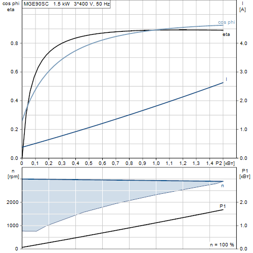
Данные каталога MGE90SC
| Наименование продукции | MGE90SC |
| Производственный номер | 98190189 |
| EAN номер | 5711491196213 |
Описание MGE90SC
Основные данные MGE90SC
| Данные на табличке электродвигателя | CE,C-TICK |
| Модель | I |
| Охлаждение | IC 411 |
Изображение MGE90SC
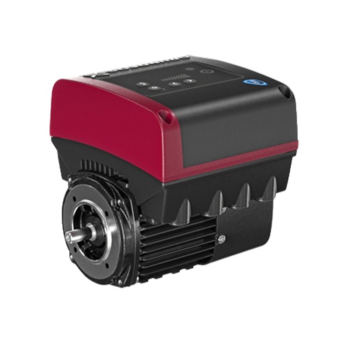
Примечание к изображению: Внимание! Фотография продукта может отличаться от существующего.
Данные электрооборудования MGE90SC
| Тип электродвигателя | 90SC |
| Номинальная мощность — P2 | 1.5 кВт |
| Промышленная частота | 50 Hz |
| Номинальное напряжение | 3 x 380-500 V |
| Номинальный ток | 2,90-2,40 A |
| Cos фи — характеристика мощности | 0,92-0,84 |
| Номинальная скорость | 360-4000 об/м |
| Номинальный вращающий момент при полной нагрузке | 5 Нм |
| Момент инерции | 0.0005 кг м2 |
| Энергоэффективность | 88,0% |
| Класс защиты (IEC 34-5) | IP55 |
| Класс изоляции (IEC 85) | F |
| Защита электродвигателя | Да |
| Тепловая защита | ELEC |
| Направление вращения | CW |
| Монтажн. обозначение по IEC 34-7 | IM B14/V18 |
Характеристика двигателя MGE90SC
Монтаж MGE90SC
| Диапазон температуры окружающей среды | -20 .. 50 °C |
| Размер фланца электродвигателя | FT115 |
Устр-ва управл-ия MGE90SC
| Панель управления | HMI200 — Стандарт |
| Общ.модуль | НЕТ |
| Функциональный модуль | FM300 — Advanced (Расширенный) |
Другое MGE90SC
| Маркировка | Grundfos Blueflux |
| Нетто вес | 14 кг |
| № структурного файла | 98373206 |
Габаритный чертеж MGE90SC
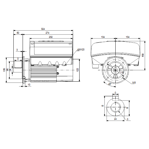
| Примечание | Правовая оговорка |
| Внимание! Все величины даны в [мм], если не указано иное. | На данном упрощённом габаритном чертеже представлены не все компоненты. |
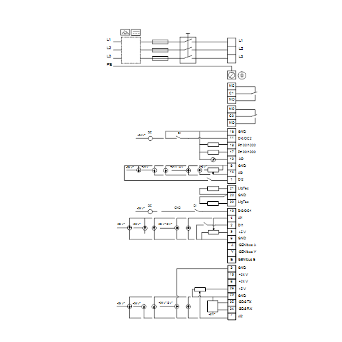
Схема подключений MGE90SC


You can identify the motor by means of the
nameplate on the terminal box.
4.1 Nameplate
The motor nameplate is located on the side of the
terminal box. See fig. 1, pos. A.
Type :
P.C. :
INPUT
P.N. :
Serial no :
U
in
:
~
DE :
Env.Type :
TEFC
NDE :
SF
:
CL:
f
:
in
Wgt :
kg
T
amb
:
F
PF:
I
SF Amp
:
A
Fig. 1
Nameplate location
Figure
2
shows the nameplate. The position
numbers refer to the table below.
1
2
3
4
Type :
P.C. :
P.N. :
— V
DE :
Env.Type :
NDE :
PF
:
o
Wgt :
kg
T
:
amb
27
26
25
24
Fig. 2
Nameplate, MGE motors
Pos.
Description
1
Type designation
2
Product number
3
Drive-end bearing
4
Version number
5
Environmental type
6
Production code (year and week)
7
Supply voltage [V]
8
Rated power output [kW]
9
Power board
10
Functional module type
11
CE mark and approvals
12
Part number of nameplate
13
Grundfos logo
14
Grundfos company address
OUTPUT
VARIANT
P2
:
Hp
PB
:
V
n max:
rpm
FM
:
Hz
Eff
:
HMI
:
Made in Hungary
I
1/1
:
A
CIM
:
DK — 8850 Bjerringbro, Denmark
A
5
6
7
INPUT
U in
:
IP:
~
CL:
f in
:
C
I
:
1/1
23
22
21
20
8
9
10
OUTPUT
VARIANT
P2
:
kW
PB
:
V
n max:
rpm
FM
:
Hz
Eff
:
HMI
:
:
A
CIM
19
18
17
16
Pos.
Description
15
Country of origin
16
Human Machine Interface type
17
CIM module type
18
Motor efficiency
19
Maximum motor speed [min
20
Maximum input current [A]
21
Mains frequency [Hz]
Enclosure class according to IEC
22
60034-5
23
Insulation class according to IEC 62114
24
Maximum ambient temperature [°C]
25
Power factor
26
Weight [kg]
27
Non-drive-end bearing
11
12
Made in Hungary
DK — 8850 Bjerringbro, Denmark
15
14
13
-1
]
5
Описание
Спецификация
Наименование продукта MGE90SC
№ продукта 98190199
EAN код 5711491196312
Технические данные
Данные на табличке электродвигателя CE,CURUS,EAC
Модель I
Охлаждение IC 411
Cable gland entry 4xM20 заглушка
Монтаж
Диапазон температуры окружающей среды -20 .. 50 °C
Размер фланца электродвигателя FT115
Данные электрооборудования
Стандарт электродвигателя IEC
Тип электродвигателя 90SC
Класс энергоэфф-ти IE5
Номинальная мощность — P2 1.5 кВт
Частота питающей сети 50 Hz
Номинальное напряжение 3 x 380-500 В
Номинальный ток 2.90-2.40 A
Cos фи — характеристика мощности 0.92-0.85
Номинальная скорость 360-4000 об/м
Номинальный вращающий момент при полной нагрузке 5 Нм
Момент инерции 0.0005 кг м²
Энергоэффективность 88.9%
Эффективность электродвигателя при полной нагрузке 88.9 %
Степень защиты (IEC 34-5) IP55
Класс изоляции (IEC 85) F
Встроенная защита электродвигателя ELEC
Тепловая защита ELEC
Монтажн. обозначение по IEC 34-7 IM B14/V18
Bearing insulation type N-end Стальной подшипник
Cable gland entry 4xM20 заглушка
Система управления
Панель управления HMI200 — Стандарт
Общ.модуль НЕТ
Функциональный модуль FM200 — Standard (Стандартный)
Другое
Масса нетто 14 кг
Конфигурац. файл № 98373206
Цвет/Тип NCS 9000 полировка 40+-10 /гальванопокрытие
Технические характеристики «Электродвигатель Grundfos KIT MGE90SC 2-FT115 3R430-2 1.5kW 98190199»
Внимание к мелочам — черта профессионалов
![]()
Заказать
Данные каталога MGE90SC
| Наименование продукции | MGE90SC |
| Производственный номер | 98190189 |
| EAN номер | 5711491196213 |
Описание MGE90SC
Основные данные MGE90SC
| Данные на табличке электродвигателя | CE,C-TICK |
| Модель | I |
| Охлаждение | IC 411 |
Изображение MGE90SC
Примечание к изображению: Внимание! Фотография продукта может отличаться от существующего.
Данные электрооборудования MGE90SC
| Тип электродвигателя | 90SC |
| Номинальная мощность — P2 | 1.5 кВт |
| Промышленная частота | 50 Hz |
| Номинальное напряжение | 3 x 380-500 V |
| Номинальный ток | 2,90-2,40 A |
| Cos фи — характеристика мощности | 0,92-0,84 |
| Номинальная скорость | 360-4000 об/м |
| Номинальный вращающий момент при полной нагрузке | 5 Нм |
| Момент инерции | 0.0005 кг м2 |
| Энергоэффективность | 88,0% |
| Класс защиты (IEC 34-5) | IP55 |
| Класс изоляции (IEC 85) | F |
| Защита электродвигателя | Да |
| Тепловая защита | ELEC |
| Направление вращения | CW |
| Монтажн. обозначение по IEC 34-7 | IM B14/V18 |
Характеристика двигателя MGE90SC
Монтаж MGE90SC
| Диапазон температуры окружающей среды | -20 .. 50 °C |
| Размер фланца электродвигателя | FT115 |
Устр-ва управл-ия MGE90SC
| Панель управления | HMI200 — Стандарт |
| Общ.модуль | НЕТ |
| Функциональный модуль | FM300 — Advanced (Расширенный) |
Другое MGE90SC
| Маркировка | Grundfos Blueflux |
| Нетто вес | 14 кг |
| № структурного файла | 98373206 |
Габаритный чертеж MGE90SC
| Примечание | Правовая оговорка |
| Внимание! Все величины даны в [мм], если не указано иное. | На данном упрощённом габаритном чертеже представлены не все компоненты. |
Схема подключений MGE90SC