Содержание
- Как подключить вай-фай камеру — подробная инструкция
- Что такое Wi-Fi камера, как она работает
- Как подключить вай-фай камеру к компьютеру или ноутбук
- Настройка Wi-Fi камеры
- Настройка IP-камеры
- Настройка экшен-камеры
- Настройка видеорегистратора и камеры заднего вида
- Как подключить камеру к телефону через Wi-Fi
- Подключение IP-камеры
- Подключение экшен-камеры
- Подключение видеорегистратора и камеры заднего вида
- Как подключить мини камеру к телефону?
- A9 WiFi mini DV
- Инструкция.
- H.264 -1080P удаленная беспроводная скрытая камера
- APP скачать программное обеспечение
- Подключение телефона к камере
- Настройка камеры
- Характеристики камеры А9
Как подключить вай-фай камеру — подробная инструкция
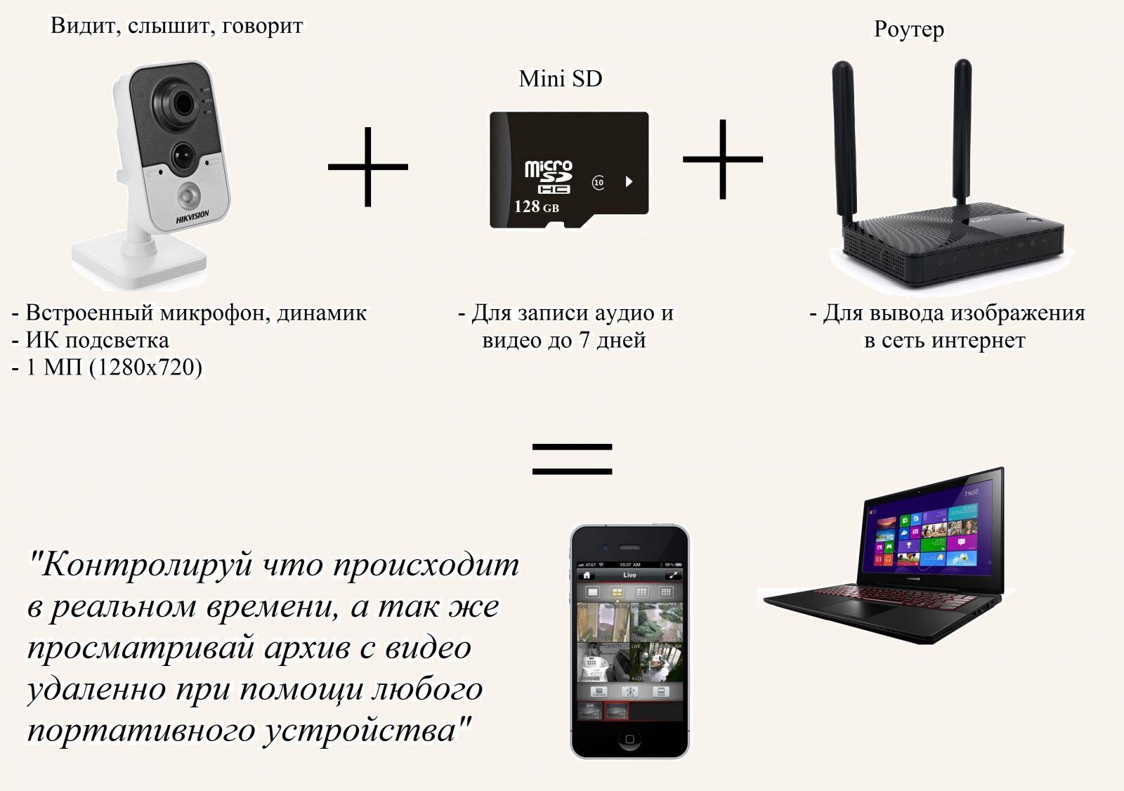
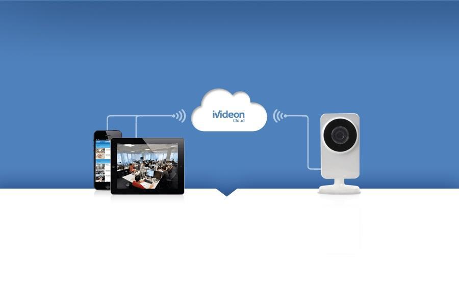
Безопасность и конфиденциальность играют огромную роль в современном мире. Во многом они обеспечиваются цифровыми технологиями и специальными приборами. Одним из них является камера видеонаблюдения, работающая по технологии Wi-Fi. Она представляет собой достаточно мощный инструмент для повышения безопасности офиса, дома, складского помещения или приусадебного участка. Необходимо более подробно разобраться, как настроить IP-камеру через Wi-Fi, что она собой представляет и как ее подключить.
Что такое Wi-Fi камера, как она работает
Прежде чем разобраться с тем, как подключить вай-фай камеру, следует понять, что это вообще такое. Wi-Fi камеры видеонаблюдения — это одна из веток IP-технологии. Они обладают собственным веб-сервером, моментально производят сжатие видео для экономии свободного места, а также обладают все теми же плюсами, что и обычные IP-камеры. Разница между ними заключается только в способе передачи данных и предварительной настройке соединения.
Интернет-наблюдение — удобная вещь
Видеокамеры, которые работают по технологии Wi-Fi, представляют собой обычные беспроводные камеры, поддерживающие передачу снятых данных через Wi-Fi. Преимущество таких устройств очевидно: не нужно протягивать или прокладывать провода или кабеля для передачи сигналов в регистратор, роутер или другие девайсы.
Обратите внимание! Видеокамеру, работающую по вай-фай, устанавливают в тех местах, куда провода протянуть проблематично, или в помещениях с уже готовым и красивым ремонтом.
Необходимо понимать, что эти устройства не полностью автономные, так как они должны получать бесперебойное электрическое питание, чтобы продолжать снимать видео. В любом случае один кабель прокладывают — это шнур от блока питания. Обычно последний используется на 12 В, а вставляется в обычную домашнюю розетку на 220 В.
Wi-Fi камеры могут работать без проводов, подключиться к ним просто
Как подключить вай-фай камеру к компьютеру или ноутбук
Способов подключения Wi-Fi камер существует несколько. Выглядят они следующим образом:
- автономный режим, когда устройство не подключается ни к чему, а просто производит запись, кодирует, сжимает и отправляет на жесткий диск, SD-карту и т. д.;
- соединение с беспроводным Wi-Fi видеорегистратором, который принимает ее сигналы и передаваемые данные;
- использование с персональными компьютерами или ноутбуками. Один из самых распространенный вариантов, который приобрел свою популярность за простоту настройки и универсальность.
Как было сказано, люди часто подключают видеокамеры к персональным компьютерам, обходя стороной видеорегистраторы. Первый способ же является непрактичным, так как не получится в режиме реального времени следить за всем, что попадает в объектив устройства.
К сведению! Самая простая схема подключения основана на использовании телевизора с поддержкой Wi-Fi, но если нужно не только следить, но и производить фиксацию, этого будет мало. Для этого и пользуются ПК или ноутбуком с вместительным жестким диском.
Все, что требуется для подключения беспроводной Wi-Fi камеры — установка специальных драйверов и программного обеспечения прибора на ПК или ноутбук. Далее просто создается соединение между двумя приборами.
Используемый для просмотра и сохранения видеозаписей компьютер должен поддерживать беспроводную передачу данных, то есть иметь встроенный или внешний адаптер Wi-Fi.
У такого вида камер есть свои недостатки, которые заключаются в том, что сигналы и электромагнитные волны, связывающие устройства, могут значительно слабеть из-за прохождения сквозь стены и другие препятствия. При их установке этот факт заранее продумывают. Также по воздуху сигнал идет и обрабатывается медленнее, чем по кабелю, а значит, имеет место быть задержка в воспроизведении потоковой записи.

Набор для подключения интернет-видеокамеры
Настройка Wi-Fi камеры
Процесс конфигурирования айпи-камер и беспроводного видеооборудования обычно не занимает много времени. Благодаря представленным ниже пошаговым инструкциям можно настроить соединение за считанные минуты.
Важно! Единственные трудности могут возникнуть только на этапе подключения к роутеру, так как не каждая камера может им поддерживаться.
Настройка IP-камеры
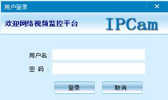
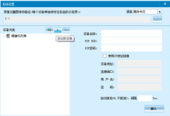
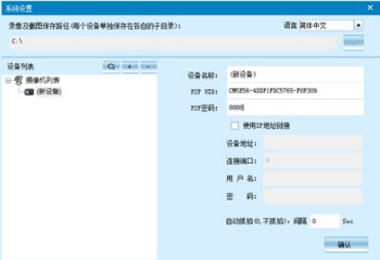
Как уже стало понятно, отличие IP-камеры от Wi-Fi оборудования заключается в способе подключения. Первый вариант всегда должен быть подсоединен к ПК по специальному кабелю. Настройка осуществляется через специальную программу, которая находится на диске, идущем в комплекте с оборудованием, или через любой браузер, где будет доступен веб-интерфейс. В этом плане видеокамеры похожи на обычные роутеры, которые также имеют адрес настроек, логин и пароль для входа в них.
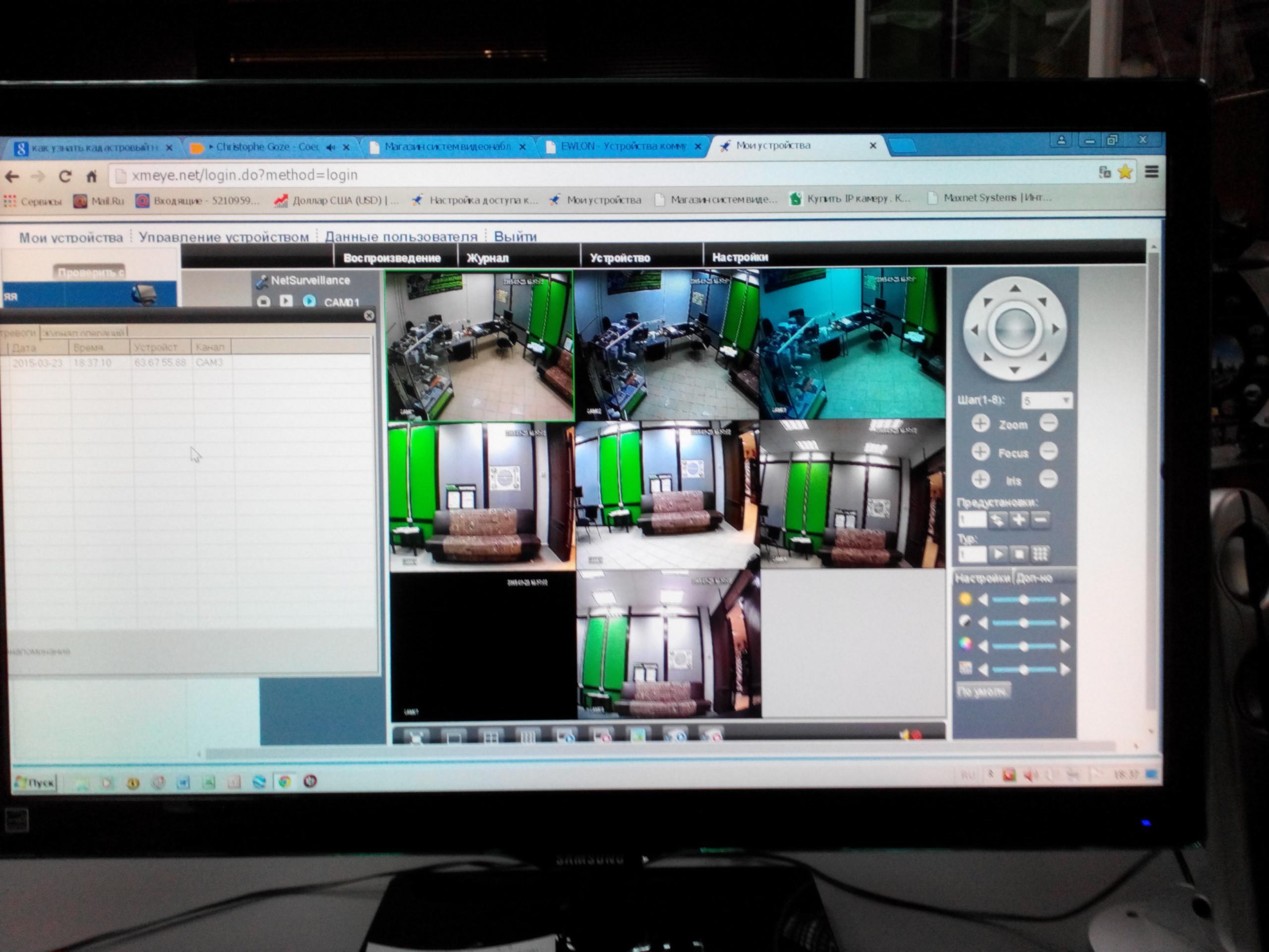
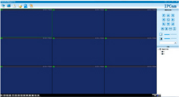
Просмотр изображения в видеокамеры на ПК
Настройка экшен-камеры
С экшен-камерами также все просто:
- Включают девайс, так как в противном случае компьютер попросту не увидит подключение.
- Переходят в меню видеокамеры и активируют режим «USB-соединение» или «Mass Storage».
- Соединяют два устройства простым USB-кабелем.
- Дожидаются распознавания гаджета и автоматической установки нужного ПО.
- Открывают хранилище камеры как простой съемный носитель.
Важно! Если требуется осуществить беспроводное подключение, то оба устройства должны поддерживать технологию Wi-Fi.
Просмотр потокового видео, которое снимает экшен-видеокамера, возможен через специальное ПО, часто зависящее от модели и производителя.
Настройка видеорегистратора и камеры заднего вида
Порядок действий при конфигурировании видеорегистратора выглядит следующим образом:
- Соединить видеорегистратор и персональный компьютер с помощью патч-корда. В параметрах регистратора задать базовые сетевые настройки: SSID и пароль.
- Связать аналогичным патч-кордом камеру с ПК. Перейти в веб-интерфейс видеокамеры и найти раздел, который посвящен беспроводным конфигурациям.
- Подключить камеру к вай-фай роутеру. Для этого указывают созданную или старую беспроводную сеть, код доступа от этой сети и режим шифрования. Главное — не забыть активировать параметр «Подключаться автоматически».
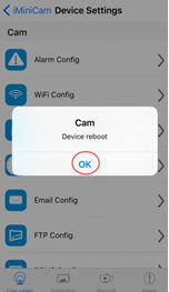
- Перезагрузить видеокамеру и отключить ее от роутера.
- Перейти в регистратор и добавить любое настроенное видеооборудование на нужный канал связи. Как только это будет сделано, на экране сразу же появится картинка.
Способов соединения камер с ПК или телефонами множество
Как подключить камеру к телефону через Wi-Fi
Иногда люди хотят иметь доступ к потоковому видео со своих камер напрямую в телефоне. Это удобно, но требует определенной последовательности действий для подключения. Ниже рассмотрено, как подключить вай-фай или IP-камеру к телефону.
Подключение IP-камеры
В случае использования цифровой беспроводной видеокамеры с наличием облачного сервиса P2P процесс выглядит просто:
- Устанавливают приложение облачного сервиса, который используется в видеооборудовании.
- Создают в нем новую учетную запись, если старой не имеется.
- Проводят синхронизацию устройств и их подключение к одной сети.
Обратите внимание! Если это именно IP-камера, которая проводом подключается к видеорегистратору, то придется, если он не поддерживает вай-фай, подключать к нему еще и роутер. Не факт, что такая связка будет стабильно работать из-за различных проблем с совместимостью.
Облачный сервис для подключения
Подключение экшен-камеры
В первую очередь необходимо скачать и установить на телефон соответствующее программное обеспечение.
Важно! Его поставляет производитель. Если вдруг соединения не происходит, то следует проверить его версию на официальном сайте, а также убедиться в том, что беспроводная сеть достаточно стабильна.
Разные видеокамеры обладают разными приложениями и алгоритмами подключения. В общем случае он выглядит так:
- Включить экшен-устройство.
- Активировать беспроводной Wi-Fi модуль, через который будет осуществляться взаимодействие. Он также представлен аналоговой кнопкой или специальным пунктом в меню настроек.
- Установить на телефон или планшет специальное программное обеспечение от производителя.
- Осуществить соединение устройств в одной сети.
- Войти в установленное приложение и синхронизироваться с выбранной моделью видеокамеры.
Подключение видеорегистратора и камеры заднего вида
Подобное подключение происходит аналогично случаю для персонального компьютера, описанного выше. Если регистратор поддерживает связь по Wi-Fi, то соединение будет осуществлено напрямую. В противном случае потребуется подключаться через роутер. Естественно, для этого на телефоне должны быть заранее установлены специальные программы.
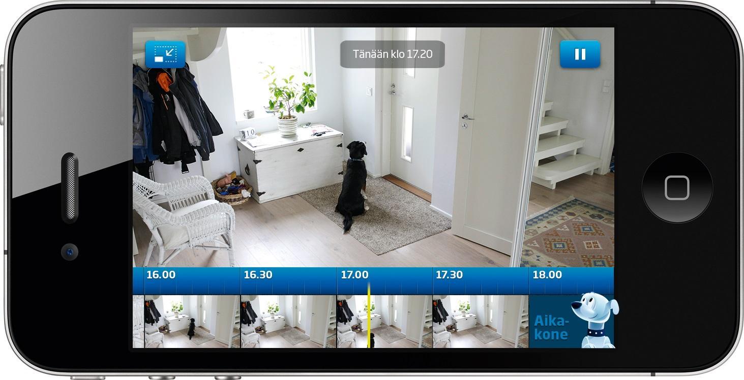
Потоковое наблюдение с телефона
Подключение Wi-Fi камеры к компьютеру или мобильному телефону — процесс не сложный и достаточно быстрый. Кроме того, неважно, к какому смартфону будет осуществляться подключение: андроиду или айфону.
Источник
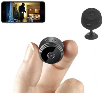
Как подключить мини камеру к телефону?
Уточните пожалуйста, какая у вас модель мини камеры.
Но алгоритм подключение беспроводной Wi-Fi мини IP камеры примерно такой:
Удаленное подключение через смартфон
На смартфоне под управлением iOS или Android зайдите в AppStore или, соответственно, Google Play Market и установите приложение SanCam.
Установите карту памяти и включите мини камеру, переведя переключатель питания в положение On: будет гореть синий индикатор и медленно мигать розовый, питание мини IP-камеры включено.
Не производите никаких действий и дождитесь полной загрузки мини камеры – это займет примерно 2 минуты.
Примечание. Вы можете подключать беспроводную камеру к зарядному устройству вне зависимости от того, в каком она находится режиме.
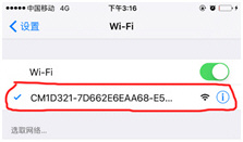
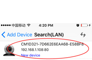
Включите на смартфоне Wi-Fi и подключитесь к сети GS**-**—** (что соответствует ID-номеру видеокамеры).
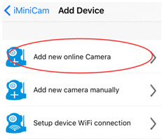
Запустите установленное приложении и в появившемся окне нажмите на + и далее Add new online Device -> Search(Lan).
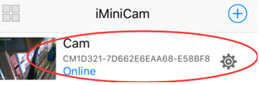
После того, как Ваша видеокамера будет найдена – нажмите на нее для добавления, а затем нажмите кнопку ОК. Мини видеокамера появится на главном экране и будет доступна для просмотра и настройки. Пароль, используемый по умолчанию для доступа к видеокамере: 8888
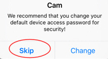
Примечание. При первом подключении к видеокамере, приложение выводит сообщение: We recommend that you change your default camera access password for security. Нажатие кнопки Change переводит в меню смены пароля, нажатие Skip позволяет игнорировать рекомендацию по смене пароля.
Источник
A9 WiFi mini DV
HD Камера — HD запись и просмотр в реальном времени.
Широкий угол обзора — угол 150 градусов, камера обеспечивает широкий охват сцены, не пропустит ничего, что произошло в вашем доме.
Ночное видение — камера обеспечивает отличное ночное видение, вы можете контролировать даже в темноте.
Циклическая запись — в процессе записи после заполнения памяти камера A9 автоматически удаляет предыдущее видео и сохраняет последнее видео.
Датчик движения — видео будет записано при обнаружении движения, что сделает ваш дом или офис более безопасным. Идеально подходит для наблюдения за ребенком, наблюдения за домашними животными и домашней безопасности. Вы можете знать, что происходило, когда вас не было дома.
Мини размер — способы крепления: стоя / магнитная палочка / стена / флип.
Инструкция.
H.264 -1080P удаленная беспроводная скрытая камера
Камера A9 использует уникальный ультрапортативный дизайн, ее можно применять в различных областях, она очень удобна, безопасна и приносит красочную жизнь для вас, пожалуйста, правильно установите камеру в соответствии с инструкцией.
Нажмите кнопку ON / OFF для включения, нажмите и удерживайте кнопку ON / OFF в течение 3 секунд, чтобы выключить. (Клавиша MODE — это кнопка сброса. Нажмите и удерживайте в течение 5 секунд в состоянии включения питания, чтобы восстановить заводские настройки после автоматического перезапуска)
Синий свет — индикатор питания.
Зеленый индикатор — индикатор WIFI
Красный — индикатор заряда
APP скачать программное обеспечение

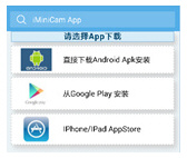
Способ 1: Сканируйте код QR (рисунок 1) напрямую, чтобы перейти к экрану загрузки (рисунок 2). Выберите подходящее программное обеспечение для загрузки в соответствии с вашей системой мобильного телефона. (Примечание:  . Этот вид установки доступен только для материкового Китая).
Способ 2. Для телефонов Android найдите приложение Google с названием «HDMiniCam» в Google Play, загрузите и установите его.
Для Iphone, приложение APP под названием «HDMiniCam» в App Store, загрузите и установите его.
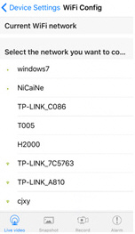
Подключение телефона к камере
Введите настройки телефона, где находится сигнал WIFI, найдите сигнал (это уникальный номер UID машины для каждой машины) и подключите. как показано на рисунке
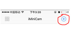
Затем откройте телефон APP (IMINICAM), как показано на рисунке, этот сигнал UID устройства UID каждой машины отличается, даже после нажатия на знак плюс, показанный выше, чтобы добавить в камеру, как показано ниже.
Нажмите, чтобы начать просмотр онлайн камеры.
Настройка камеры
Нажмите на значек  . Настройте камеру..
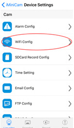
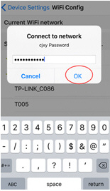
Введите пароль для камеры.
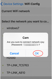
Хорошо, подождите, пока камера перезагрузится, это займет около 40 секунд. Онлайн с камеры отключится, тогда вы сможете получить удаленный доступ, и когда телефон WIFI и камеры в той же сети, которая является локальной сетью, или любой другой телефон, подключенный к сотовому телефону 4G WIFI APP, автоматически переподключат камеру после успешного подключения вы можете посмотреть видео.
1) Загрузите компьютерный клиент, загрузив адрес http://112.124.40.254:808/PCTools.zip и установите

2) Нажмите на установку, появится окно, как показано на рисунке. (Смотри ниже)

Введите имя пользователя (admin) Нажмите «Войти» (Примечание: исходное имя пользователя — «admin» без пароля).
Enter 
Enter 
Enter 
Enter 
Характеристики камеры А9
Соотношение разрешения: 1080P / 720P / 640P / 320P
Формат видео: AVI
Частота кадров: 25
Угол обзора: 150 градусов
Камера обнаружения движения Съемка прямой линии 6 метров
Минимальное освещение: 1LUX
Продолжительность видео: более 1 часа
Сжатый формат: H.264
Потребление: 240 мА / 3,7 В
Температура хранения: -20-80 градусов по Цельсию
Рабочая температура: -10-60 градусов по Цельсию
Рабочая влажность: 15-85% относительной влажности
Тип карты памяти: TF карта
Программное обеспечение плеера: VLCPlayer / SMPlayer
Операционная система компьютера: Windows / Mac OS X
Операционная система мобильного телефона: Android / iOS
Веб-браузер: IE7 и выше, Chrome, Firefox Safari.etc
1. Почему видеозапись не является гладким?
Вы должны выбрать подходящее разрешение для просмотра в соответствии с вашим Интернетом.
2. Почему SD-карта не работает?
SD-карта должна быть отформатирована, если вы используете ее впервые.
3. Почему нет соединения с сетью?
Выберите правильный способ подключения в соответствии с вашей сетью
4. Почему приложение удаленного просмотра видео с SD-карты не является плавным?
Настроить видеооборудование в соответствии с разрешением вашего мобильного телефона.
5. Как сбросить пароль?
Нажать кнопку сброса с 10 секундами и восстановить заводские настройки.
Замечания:
Название устройства P2P UID
Пароль 8888, если вы изменили.
Специальное примечание:
1. Если камера не подключена к маршрутизатору, выполните сброс даже после горячей настройки компьютера.
2. Если камера не читает карту памяти, или мобильный телефон в локальной сети, расширенные настройки в фоновом формате после использования.
3. Сброс выключения: пожалуйста, снова выключите и перезагрузите, когда вы увидите красный свет.
Источник
Adblock
detector
○
User Manual
4CH DVR
This document contains preliminary information and subject to change without notice.
1
Cautio n
RISK OF ELECTRIC
SHOCK DO NOT OPEN
WARNING
TO REDUCE THE RISK OF FIRE OR
ELECTRIC SHOCK, DO NOT EXPOSE
THIS APPLIANCE TO RAIN OR
MOISTURE.
CAUTION:
TO REDUCE THE RISK OF
ELECTRIC SHOCK, DO NOT REMOVE COVER
(OR BACK). NO USER SERVICEABLE PARTS
INSIDE. REFER SERVICING TO QUALIFIED
SERVICE PERSONNEL.
This symbol is intended to alert the user to the presence of unprotected “Dangerous voltage» within the product’s enclosure that may be strong enough to cause a risk of electric shock.
This symbol is intended to alert the user to the presence of important operating and maintenance (servicing) instructions in the literature accompanying the appliance.
NOTE: This equipment has been tested and found to comply with the limits for a class digital device, pursuant to part 15 of the FCC Rules. These limits are designed to provide reasonable protection against harmful interference when the equipment is operated in a commercial environment.
This equipment generates, uses, and can radiate radio frequency energy and, if not installed and used in accordance with the instruction manual, may cause harmful interference to radio communications.
Operation of this equipment in a residential area is likely to cause harmful interference in which case the user will be required to correct the interference at his own expense.
Disposal of Old Electrical & Electronic Equipment (Applicable in the European
Union and other European countries with separate collection systems)
This symbol on the product or on its packaging indicates that this product shall not be treated as household waste. Instead it shall be handed over to the applicable collection point for the recycling of electrical and electronic equipment. By ensuring this product is disposed of correctly, you will help prevent potential negative consequences for the environment and human health, which could otherwise be caused by inappropriate waste handling of this product. The recycling of materials will help to conserve natural resources. For more detailed information about recycling of this product, please contact your local city office, your household
2
Table of Contents
CHAPTER 1 PACKING DETAIL AND INSTALLATION 5
1-1 PACKING __________________________________________________________ 5
1-2 Hard Disk Installation _________________________________________________ 6
CHAPTER 2 PANEL LOCATION 8
2-1 FRONT PANEL CONTROLS____________________________________________________8
2-2 REAR PANEL CONNECTORS _________________________________________ 9
CHAPTER 3 LIVE, PLAYBACK AND PTZ OPERATIONS 10
3-1 LIVE Mode ________________________________________________________ 13
3-2 PLAYBACK Mode __________________________________________________ 15
3-3 PTZ Mode ________________________________________________________ 17
CHAPTER 4 MAIN MENU SETUP 18
4-1 RECORD SETUP __________________________________________________ 19
4-1.1 Quality & Frame Rate Setup _____________________________________ 19
4-2 EVENT SETUP ____________________________________________________ 19
4-2.1 MOTION SETUP ______________________________________________ 20
4-2.1.1 MOTION AREA SETUP______________________________________________ 21
4-2.2 SENSOR SETUP______________________________________________ 22
4-3 SCHEDULE SETUP ________________________________________________ 23
4-3.1 Schedule Record Setup _________________________________________ 23
4-3.2 Holiday Setup ________________________________________________ 24
4-4 CAMERA SETUP ___________________________________________________ 24
4-5 ACCOUNT SETUP__________________________________________________ 25
4-5.1 Permission Setup______________________________________________ 26
4-6 NETWORKING SETUP ______________________________________________ 27
4-6.1 NETWORKING SETUP _________________________________________ 27
4-6.1.1 DHCP _____________________________________________________________ 27
4-6.1.2 LAN ______________________________________________________________ 27
4-6.1.3 ADSL ___________________________________________________________ 27
4-6.2 HTTP Setup_________________________________________________ 28
4-6.3 Mail Setup __________________________________________________ 29
4-7 PTZ & RS485 SETUP _______________________________________________ 30
4-8 SYSTEM SETUP ___________________________________________________ 31
4-8.1 DISPLAY SETUP ______________________________________________ 32
4-8.2 DATE/TIME SETUP ____________________________________________ 33
4-8.2.1 CHANGE DATE & TIME ___________________________________ 33
4-8.2.2 TIME ZONE SETUP ______________________________________ 33
4-8.2.3 INTERNET TIME SETUP __________________________________ 34
4-8.3 BUZZER & RELAY SETUP ______________________________________ 34
4-8.4 SPOT SETUP ________________________________________________ 35
4-9 UTILITY SETUP____________________________________________________ 36
4-10 DIAGNOSTIC_____________________________________________________ 37
CHAPTER 5 BACKUP & SEARCH 38
5-1 BACKUP SETUP ___________________________________________________ 38
5-2 SEARCH SETUP ___________________________________________________ 39
5-2.1 EVENT SEARCH ______________________________________________ 39
5-2.1.1 CRITERIA SETUP FOR EVENT SEARCH _____________________ 40
5-2.2 TIME SEARCH 41
3
CHAPTER 6 NETWORK SURVEILLANCE 42
6-1 AP Software Installation and Setup _____________________________________ 42
6-2 AP Software Operation_______________________________________________ 45
CHAPTER 7 SPECIFICAITONS 46
CHAPTER 8 MOBILE APPLICATION INSTALLATION AND USAGE 48
8-1Mobile Application Installation and Operation for Symbian System. _____________ 48
8-1.1 Mobile Application Installation ____________________________________ 48
8-1.2 Mobile Application Operation _____________________________________ 49
8-1.2.1 Add New Login DVR_____________________________________ 49
8-1.2.2 Logging Onto the DVR ___________________________________ 49
8-1.2.3 Modify the Login Information of DVR _______________________ 50
8-1.2.4 Delete the Login Information of DVR _______________________ 50
8-1.3 Live Monitoring Operation _______________________________________ 51
8-1.3.1 Scroll the Image ________________________________________ 51
8-1.3.2 Image Quality Setup _____________________________________ 51
8-1.3.3 Channel Display _________________________________________ 51
8-1.3.4 Size of Image __________________________________________ 52
8-1.3.5 Rotate the image ________________________________________ 52
8-1.3.6 Alarm _________________________________________________ 52
8-2 Mobile Application Installation and Operation for Windows Mobile System _____ 53
8-2.1 Mobile Application Installation ____________________________________ 53
8-2.2 Mobile Application Operation _____________________________________ 54
8-2.3 Operation under the LIVE monitoring. ______________________________ 54
8-2.3.1 Operation uner the LIVE monitoring for Jrviewer ______________ 55
8-2.3.2 Operation under the LIVE monitoring for H264 Pocket _________ 56
4
CHAPTER 1 PACKING DETAIL AND INSTALLATION
1-1 PACKING
2. Quick Start
5. CD
1. DVR
3. IR Remote Control
6. SATA Cord x1
4. Batteries x2
7. Screws x4
8. Power Adaptor
9. Power Cord
5
1-2 Hard Disk Installation
Step 1) Remove the 3 screws from DVR as cycled below.
Step 2) Remove the front cover from DVR as indicated by the arrow.
Step 3) Place the HDD on the HDD plate and connect the power and the
SATA cables.
6
7
Step 4) Screw the bottom of the DVR as indicated as cycled.
Step 5) Place the bottom of DVR and screw.
CHAPTER 2 PANEL LOCATION
2-1 FRONT PANEL CONTROLS
○
○
USB 2.0 Port
Port for USB external devices.
○
LED Display-
Power
DVR Power is on.
○
LED Display —
HDD
○
LED Display —
LAN
Hard disk is in use.
Connected to the internet.
○
LED Display-
LOGIN
Remote user logged in.
○
LED Display —
REC
DVR Recording.
○
LED Display —
PLAY
○
IR Sensor
DVR Playing back.
Input sensor for the remote control.
○
8
2-2 4CH REAR PANEL CONNECTORS
○
○
7
○
⑩
○
DC 12V
Socket for a DC 12V input.
○
SPOT monitor
BNC port to display full screen image of all installed cameras in sequence.
BNC port for the main monitor.
○
MAIN monitor
○
VIDEO IN
○
AUDIO IN
BNC input ports for cameras, 16 in total.
⑩ EXTERNAL I/O
RCA input port for audio signal.
○
AUDIO OUT
RCA output for audio signal.
○
NTSC/PAL
Switch Switch between NTSC and PAL format.
○ LAN
Network port.
○
VGA
VGA port.
EXTERNAL I/O port (see below for pin definition)
9
CHAPTER 3 LIVE, PLAYBACK AND PTZ OPERATIONS
3-1 LIVE Mode
You can monitor all the channels, listen to audio signal and have some related operations under
LIVE mode. This paragraph describes the IR remote control, mouse operation and on screen graphical icons under LIVE mode.
Table 3-1.1 Remote control functions under the LIVE mode
Button Description
REC
LOCK
PLAY
T-SRH
AUTO
PTZ
Start/Stop recording.
Enable/Disable the Keypad function.
Start playing back.
Display search menu.
In AUTO mode, all available channels will be cycled through in full screen.
Start/Stop PTZ control.
Switch to quad display.
Switch to 9-channel display. 4-CH doesn’t support this function.
Switch to 13-channel display. 4-CH doesn’t support this function.
Switch to 16-channel display. 4-CH doesn’t support this function.
MENU
MUTE
Enable/ Disable Menu.
Switch to 1-CH audio out/Turn off live audio.
BK-UP
Display backup menu.
ENTER/MODE
Switch to full screen and quad screen.
ZOOM+
Zoom in to double the screen size by keypad or mouse operation.
ZOOM-
ZOOM
STATUS
1,2,3,4
FREEZE
PIP
OSD
Zoom out from double screen size.
Enable/ Disable double screen size display.
You can click on the channel name for choosing a specific channel.
Display Status.
Select the channel to monitor in full screen from channel 1 to 4.
Turn on/off screen freeze function.
Turn on picture-in-picture format. Click on the channel name can switch to other channels.
Turn on/off the screen display
10
Table 3-1.2 Graphical icons that will display after right-clicking your mouse under LIVE mode.
Icon Description
Resting the cursor on this icon will bring up the following four menu icons.
Main menu.
Search menu.
Backup menu.
PTZ mode.
Turn on/off recording.
Playback.
Resting the cursor on this icon will bring up the following five display icons.
FREEZE.
PIP, picture in picture
ZOOM, double the screen size
AUTO-sequence
LOCK, activate the key lock.
Full screen display.
Quad display.
11
Table 3-1.3 Description of on screen graphical icons in LIVE mode
Icon Description
Recording is on
Live Audio is on
Live Audio is off
Motion detected on the channel
Sensor triggered on the channel
Video loss detected on the channel
USB device detected
Remote user currently logging into DVR
Timer recording is on
Red:Timer is set and recording has been started
White:Timer is set but recording has not yet been started
AUTO-seq is on
2X
2X zoom in is on
Freeze is on, screen is frozen
LOCK is on
PTZ control is on
1~8
IR remote signal has been set to 1-8 to correspond to your 1-to-8 remote controller; the standard remote controller can’t control this DVR under this situation. It can only be controlled by1-to-8 remote controller (optional device).
12
3-2 PLAYBACK Mode
Switch to PLAYBACK mode by pressing “PLAY” under the LIVE mode, the graphical icon will show up on the upper center of the screen and the operation panel ( see below picture) will show up at right lower corner of the screen. You can drag the panel by mouse to place it on any location of your screen.
Table 3-2.1 Remote control functions under the PLAYBACK mode
Button Description
/
ENTER / MODE
Switch to full screen, quad, 9-channel or 16-channel display.
MENU /
Turn on/off PAUSE.
PLAY
/ SLOW
Play back at normal speed.
Play back at slower speed. The speed will be slowed to 1/2, 1/4, 1/8,
1/16 by each pressing of the button till the slowest limitation of 1/16 of the normal speed. Current playback speed is shown in the upper center of the screen.
/
/
Fast rewind. Each press increases the speed to the next level. There are six speeds: 2x, 4X, 8X, 16x, 32X and 64X.
Fast forward. Each press increases the speed to the next level. There are six speeds: 2x, 4X, 8X, 16x, 32X and 64X.
Stop playback.
13
Table 3-2.2 The mouse operation under the PLAYBACK mode.
Icon Description
「 / 」Fast rewind
「 / 」Fast forward
/
「PLAY」、「 ▌▌」Play/pause
「▲ / SLOW」slow playback
「▼ / ■」stop playback
Playback channel by channel with snap shot display
Full screen display
Quad display
14
3-3 PTZ Mode
Switch to the PTZ mode by pressing “PTZ” button under the LIVE mode. The PTZ icon will appear on upper left of the screen but it can be re-located on any place of your screen by dragging the mouse.
PRESET
Table 3-3.1 Remote Control functions under the PTZ mode
Button
Description
/ SLOW
Move PTZ up.
/
Move PTZ down.
/
/
Move PTZ to the left.
Move PTZ to the right.
ZOOM +
ZOOM —
PTZ zoom-in.
PTZ zoom-out.
FOCUS +
FOCUS —
IRIS +
IRIS —
TOUR
PTZ focus-in.
PTZ focus-out.
PTZ iris-open.
PTZ iris-close.
Activate PTZ pre-set tour.
To go to a preset location, press PRESET and a number key. DVR will save the current location.
NUMBER
NUMBER
PIP
FREEZE
ZOOM
the current location. the current location.
Set current PTZ location as the start of the line-scan.
Activate line-scan.
Set current PTZ location as the end of the line-scan.
15
Table 3-3.2 Mouse operation under the PTZ mode
Icon
Description
Leave PTZ Mode,back to the LIVE mode
Pre-set number N. (1~64)
Go to pre-set number N.
Set current PTZ location at pre-set number N.
「TOUR」,press to activate pre-set tour
Same as 「PIP」. Set current PTZ location as the start of the line-scan.
Same as 「FREEZE」. Activate line-scan.
Same as 「ZOOM」. Set current PTZ location as the end of the line-scan.
To move PTZ in 360°
PTZ zoom in; PTZ zoom out
PTZ focus in; PTZ focus out.
PTZ IRIS open, PTZ IRIS close.
Below functions need support from specific PTZ. Please check user manual of your PTZ manufacturer for detail.
AUX 1. 「AUTO」+「1」
AUX 2. 「AUTO」+「2」
AUX 3. 「AUTO」+「3」
AUX 4. 「AUTO」+「4」
AUX 5. 「AUTO」+「5」
AUX 6. 「AUTO」+「6」
AUX 7. 「AUTO」+「7」
AUX 8. 「AUTO」+「1」
「Backup」, Customized function。
16
CHAPTER 4 MAIN MENU SETUP
To enter the main menu and set up DVR, log-in account and user password are required.
The default password of the administrator is “123456”. Please check the “Account Setup” for related setup of other log-in users.
Table 4-0.1 Some definition of virtual keyboard.
Item
Description
/
Switch between capital and small letters.
Switch between numbers and letters.
Press to cancel the setup, and re-choose the login account.
Delete the last character.
Enter to identify the password. It will enter the set up menu, If the password is verified.
17
Table 4-0.2 The operation of remote control under the setting menu
MENU
Item Description
Switch to different options under one item
Switch to different items
Save setup and back to LIVE mode
ESC
ENTER
Back to Upper level of the menu
Enter the menu, or display virtual keyboard
4-1 RECORD SETUP
Item Description
HDD FULL
Record Normal
Pre Alarm Record
Audio Record
Record Motion
Record Sensor
Quality & Frame
Rate Setup
Select STOP to stop recording or OVERWRITE to reuse the HDD when HDD is full
「Stop」:Stop Recording
「Overwrite」:Start to overwrite that begin from the oldest data of
HDD, and continue to record.
Enable/Disable normal recording
Enable/Disable pre-event recording while motion or sensor is triggered but not in the recording mode. This option decides if save the pre-recording time 10 seconds data or not.
Enable/Disable Audio recording.
Enable/Disable recording while Motion is detected
Enable/Disable recording while Sensor is triggered
Setup the quality and frame rate for each channel under normal recording and event recording type.
18
4-1.1 Quality & Frame Rate Setup
Item Description
Resolution
Record Type
No.
Quality
Choose record resolution from : CIF / HD1(2CIF) / D1.
You can setup quality and FPS separately for record type.
Check/uncheck the box will enable/disable recording of that channel.
Choose from Lowest/ Low/ Normal/ High/ Highest
FPS
4-2 EVENT SETUP
Choose recording frame rate.
Item Description
Alarm Duration (Seconds)
Set up alarm duration in seconds.
Drag the white bar or press
◀ ▶ to adjust value.
Motion Setup
Sensor Setup
Enter to set up motion detection
Enter to set up sensor detection
19
4-2.1 MOTION SETUP
Item Description
Motion Detection
Motion Popup
1~4
Selected Channel Turn
Object Size
Check the box to Enable/Disable Motion Detection for all channels.
Check the box to Enable/Disable popup screen function for all channels. When motion is detected in LIVE mode, the detected channel image will pop up in full screen display.
You can setup independently for each channel.
Check the box to Enable/Disable motion detection for each channel.
Drag the white bar or press ◀ ▶ to set up Object Size
from value 1 to 15 for each channel. The lower value you set the higher sensitivity it will be.
Drag the white bar or press ◀ ▶ to set up Sensitivity from
value 1 to 15 for each channel. The lower value you set
the higher sensitivity it will be
Enter to setup motion detection area
Sensitivity
Motion Area Setup
20
4-2.1.1 MOTION AREA SETUP
There are 16×12 partitions in motion detection area. Under initializing status, motion detection area is in entire screen. Red colored area is detected; yet the undetected area is transparent. It is purple while network connected.
Item Description
LOCK/ZOOM
MUTE / PIP
STATUS
ENTER
MENU
ESC
Press LOCK/ZOOM to select entire screen as detection area.
Press MUTE/PIP to deselect entire screen as detection area.
Switch between “select” and “deselect” for cursor-dragging function
Press to function on the selected area with assigned status
Press to save the setup and leave
Press to cancel the setup and leave
21
4-2.2 SENSOR SETUP
Item Description
Sensor Detection
Check the box to Enable/Disable sensor detection for all channels.
Sensor Popup
Check the box to Enable/Disable popup screen function for all channels. When Sensor is detected in LIVE mode, the detected channel image will pop up in full screen display.
Sensor Polarity
Click or press ▼ to select between HIGH, LOW voltage for triggering sensor detection or OFF to turn off polarity for each channel
Low Polarity:Sensor has not been triggered. When connected, sensor will be turned on..
High Polarity:Sensor has been triggered. When connected, sensor status will be turned off..
Off :Sensor is deactivated, and will not be turned on/off.
22
23
4-3 SCHEDULE SETUP
Except from starting recording manually, you can also setup the recording time by weeks and schedule including normal, motion detect, and sensor detect recording type.
Page
Item Description
Holiday Setup
Click or press ▼ to select Page. Each page provides 10 schedules for setup. 5 pages in total.
Enter to setup holiday, up to 50 days, other than weekends,.
View Event Setup
View Normal/ Motion / Sensor Setup
4-3.1 Schedule Record Setup
Click on the time on the left side. The setup menu will be displayed. You can have detail setup by dates, Time and event.
4-3.2 Holiday Setup
Since holidays are different by different country and region, you can setup the holiday of your location accordingly.
4-4 CAMERA SETUP
1~4
Mask
Brightness
Contrast
Saturation
Hue
Name
Item Description
Volume
You can setup independently for each channel.
Check the box to Enable/Disable mask function for LIVE mode
Drag the white bar or press ◀ ▶ to adjust Brightness of your camera from value 1 to 255. The default value is 128.
Drag the white bar or press ◀ ▶ to adjust Contrast of your camera from value 1 to 255. The default value is 128.
Drag the white bar or press ◀ ▶ to adjust Saturation of your camera from value 1 to 255. The default value is 128.
Drag the white bar or press ◀ ▶ to adjust Hue of your camera from value 1 to 255. The default value is 128. ( This function doesn’t
support at PAL system)
Set up name of each channel
Select to adjust audio volume for CH1 to CH 4 under LIVE mode and recording mode.
24
4-5 ACCOUNT SETUP
The Account Setup menu is used to provide role-based permission independently setting for each user (maximum of 4 users) to access DVR over network. The default admin account is
「admin」and password is “123456”.
Item Description
Auto Lock
No.
Password
Permissions
After one minute without any action, the DVR will switch to LIVE mode automatically. Auto lock can function differently according to the setting below.
Function
Setting
Key lock
Auto Logout
○
Key Lock
○
Key unlock
○ ×
Disable
× ×
Check to activate the user’s account.
Enter to set up password for each user. Password can be set up to 8 characters mixed by letters and numbers with case-sensitive.
Enter to set up Permissions for each user。
Change Admin
Enter to change administrator’s password
Password
P.s.1: When logged out automatically, you will have to operate in limited authority such as operations like: Freeze the screen, Picture in picture, Zoom in/ out, switch between channels…etc. If you need to enter the Setup menu, Search menu, backup menu,
Record…etc, user’s account and password are required.
P.s.2: When the key lock automatically, remote control and mouse can’t function before entering verified password.
P.s.3:「○」: Enable the function, 「×」: Disable the function
25
4-5.1 Permission Setup
The Account Setup is set to provide individual user (maximum of 4 users) role-based permissions, including access to Setup menu, Network operation, PTZ function, Playback,
Utility, Backup and Mask on specific channels while playing back.
4-6 NETWORKING SETUP
Item Description
Connect type
Setup mode for network connection: DHCP、LAN、ADSL.
HTTP Setup
DDNS Setup
Mail Setup
Enter to set up HTTP for remote access into DVR.
Enter to Enable/Disable DDNS function and set up.
Enter to enable/disable Email notification and setup.
26
4-6.1 NETWORKING SETUP
The DVR supports DHCP, LAN and ADSL accesses for network connection.
4-6.1.1 DHCP
If the DHCP option is used for DVR network connection, an IP address is assigned by the
DHCP server automatically.
4-6.1.2 LAN
Select LAN for network connection, the following information is required.
Item Description
IP Address
Subnet Mask
Gateway
Enter IP address provided by ISP
Enter IP address of Subnet Mask provided by ISP
Enter IP address of Gate way provided by ISP
DNS
Enter DNS address provided by ISP. (Note: The correct DNS address must be entered for DDNS function).
4-6.1.3 ADSL
Select ADSL for network connection, the following information is required.
27
Item Description
User Name
Password
4-6.2 HTTP SETUP
Enter user name provided by ISP
Enter password provided by ISP
Item Description
Enable HTTP
Server
Port
Check to enable HTTP server. Users can remotely access into the
DVR over the network if the HTTP function is activated.
Enter a valid port value from 1 up to 65000. The default value is 80.
28
4-6.3 Mail Setup
E-mail can be used as a form of notification when an event occurs (VLOSS, MOTION,
SENSOR).
Item Description
Notification
SMTP Server
User Name
Password
Sender E-mail
E-mail address
Trigger Event
Enter to set up SMTP Server name.
Enter to set up User Name.
Enter to set up Password.
Enter to set up e-mail address of receivers.
Enter to set up e-mail addresses for up to 10 receivers individually.
Enter to select events to send out E-mail notifications when below circumstances happen: Motion, Sensor and Vloss (Video Loss).
29
4-7 PTZ & RS485 SETUP
The DVR allows users to control PTZ functions of your camera. To enable PTZ function, the 485 cable should be connected to the RS-485 port of DVR.
PTZ ID
Item Description
Enable PTZ
Protocol
Click the box to Enable/Disable PTZ function for each channel.
Set up the protocol of PTZ cam. The supported protocol are
PELCO-P, PELCO-D, KND, LI-LIN.
Click or press
◀ ▶
to set up PTZ ID. The valid ID value is from 1 to 64.
Select Baud Rate for PTZ from 2400、4800、9600
Baud Rate
30
4-8 SYSTEM SETUP
Item Description
DVR Name
DVR Location
The name of DVR will be shown when users login from remote access.
The location of DVR will be shown when users login from remote access
Language
Click or press ▼ to select OSD language.
Auto-Seq Interval
Click or press
◀ ▶
to set up duration time in seconds for the interval
( Seconds)
between channels under Auto-Seq mode.
Remote ID
The default Remote ID is 0, when DVR is controlled by standard remote controller. To operate DVR by optional 1-to-8 remote controller, the Remote ID from1 to 8 is required for recognition corresponding to 1-8 remote controllers and press DVR-1 button.
Display Setup
Enter to set up Display
Date/Time Setup
Enter to set up Date/Time
Buzzer & Relay
Enter to set up Buzzer & Relay
Setup
Spot Setup
Enter to set up Spot
31
4-8.1 DISPLAY SETUP
Item Description
OSD
DVR Status
Date/Time
Channel Name
Border Set
Turn On / Off OSD display
Turn On / Off DVR illustration and record status display
Turn On / Off date and time display
Turn On / Off channel name display
Set up the color of border in LIVE , PLAYBACK mode.(black、dark grey、light grey、white)
4-8.2 DATE/TIME SETUP
32
Item Description
Hour Format
Date Format
Date/Time Position
Change Date & Time
Time Zone Setup
12HOURS/ 24HOURS
MM-DD-YY/DD-MM-YY/YY-MM-DD
Choose the position of Time and Date display
Setup time and date of DVR
Set up GMT and Daylight Saving Time.
Internet Time Setup
Setup automatic synchronization with internet server
4-8.2.1 CHANGE DATE & TIME
Users are allowed to setup date and time of DVR.
4-8.2.2 TIME ZONE SETUP
In time zone setup, users can change your time zone and activate Daylight Saving Time function according to your DVR location.
Item Description
Select Time Zone
Enter to modify GMT from GMT- 13 to GMT+ 13
Daylight Saving Time
Turn on/ off Daylight Saving Time
33
4-8.2.3 INTERNET TIME SETUP
Synchronize your DVR time with internet time server.
Item Description
Automatic
Synchronization
Check to enable DVR automatic synchronization function.
Effective by this option selected, DVR will automatically synchronize the time upon rebooting or by every 24 hours after booting.
Update Now
Effectively, Date and Time show on DVR will immediately correspond with those in internet server.
4-8.3 BUZZER & RELAY SETUP
34
Item Description
KEY TONE
Relay Switch Connection
Enable/Disable keystrokes.
Set relay signal to be Normal Close (N.C.) or Normal Open (N.O.).
Buzzer Duration
ALARM BUZZER
ALARM RELAY
Set up the duration from 1~999 seconds.
Enable/Disable buzzer operation when the alarm is triggered for sensor, motion and vloss (Video Loss).
Enable/Disable the signal to be sent to the RELAY OUT blocks when the alarm is triggered for sensor, motion and vloss.
4-8.4 SPOT SETUP
The DVR has two modes of video output; one is main video output, the other is spot video output. SPOT setup is for controlling the order of channels the system cycles through in SPOT mode. User can monitor every channel in the SPOT mode.
Item Description
SPOT MODE
Channels display in spot for three different modes:
MANUAL: select channels to display manually.
SEQUENCE: Auto-sequence for all channels in order.
EVENT: Display channels with event occurred.
Interval (Seconds)
The duration time in seconds for the interval between channels under
SPOT mode.
Skip Video Loss
Whether to skip channels without video signal.
Channel
35
4-9 UTILITY SETUP
Item Description
HDD Initialization
Select to enter hard disk initialization menu. Please stop
recording before entering this menu. Enter the menu, system will show all the data (model ,volume ) of HDD that installed in DVR. Check the HDD you’d like to initialize then press “Start”. HDD initialization is successful when the status shows “Succeed”
USB Initialization
Clean up all data on USB. Enter USB initialization and press YES to clean up all data on your USB. The initialization is done when it’s showed “Succeed”.
Restore system default values
System Recovery
Reset System Events
Copy Setup to USB
Reset all the recording events in DVR.
Copy configuration to a USB device. There will be a file named “sdvr.config” on your USB.
Download Setup from USB
Download configuration from a USB device into DVR.
Upgrade
Upgrade DVR through USB.
Please stop recording and backup setup configuration before upgrading.
System will reboot automatically when the upgrade is
completed.
Notice! DO NOT TURN OFF POWER OR UNPLUG USB DEVICE DURING THE UPGRADE as it may cause incomplete firmware upgrade and damage to the DVR.
36
4-10 DIAGNOSTIC
Version
Item
IP Address
MAC Address
HDD Volume
HDD Used Rate
HDD Status
Format Time
Description
The current firmware version of DVR
The connected IP address of DVR. If disconnected from network, the screen will display” NETWORK DISCONNECT”.
MAC Address of DVR
The capacity of HDD
Percentage of space used on HDD.
Shows HDD status.
USING means the HDD is being used for recording now
GOOD/BAD means the HDD has a known/unknown format for the DVR. (Note: Please initialize your newly-installed HDD before using it, otherwise it can be recognized as BAD by DVR.)
The latest format time of HDD
37
CHAPTER 5 BACKUP & SEARCH
5-1 BACKUP SETUP
User can backup any segment of recorded data in a specified time frame. To do so, either a CD
R/W or storage device, like USB, must be connected to the DVR. The format of backup file is
IRF file that can be played by “DVRemoteDesktop.exe”
Item Description
From
To
Device
Free Space
The start time of backup file
The end time of backup file
Select USB or CD/RW as the backup device
The available space in your backup device
Refresh
Calculate
Recalculate the available space of backup device
Calculate the size of backup file
Start
Start backup operation. Be sure to calculate the size of backup file
BEFORE operating backup.
Notice! Do not unplug the USB device or turn off the DVR during the backup process to avoid unrecoverable error.
38
5-2 SEARCH SETUP
Item Description
Event Search
Press to enter event search menu
Time Search
Press to enter time search menu
5-2.1 EVENT SEARCH
The DVR automatically records events with type, time and channel information included. If there is recording data for an event, a yellow signal will be shown on the left side of time information. Rest your cursor under the line and press “enter”, or left click your mouse to playback the recording data.
39
Item Description
Criteria
Page
Date/Time
Event Type
Setup conditions of event search
Convert pages of events
Date/time when event occurred.
Event type, defined as following
VLOSS
Video Loss
MOTION
SENSOR
REMOTEIN
REMOTEOUT
Motion Detected
Sensor Detected user log-in over the network user log-out over the network
POWER ON
KEY LOCK
KEY UNLOCK
HDD FULL
System Rebooting
System key are locked
System key are unlocked
HDD is FULL
Channel
The channel where event occurred.
5-2.1.1 CRITERIA SETUP FOR EVENT SEARCH
The amount of events can be numerous. Therefore, you can facilitate event sorting by setting up “criteria”. Setup “start time” and “end time” for event search, then the search result will be limited to this specific period of time. Only checked events and channels will be sorted in event search as well.
40
5-2.2 TIME SEARCH
TIME SEARCH can search for the specific time of recording data to playback. Note that dates with recording data are marked with a red square “
□
“. System will start playing back according to the date you selected. Calendar will be shown by using mouse to click on “year” and “month”.
41
Click “date” to display recording time of that specific date with time bar. You can change time
(hour/minute/second) or click on a specific time of time bar by mouse then press “YES”. DVR will playback the selected recording data.
CHAPTER 6 NETWORK SURVEILLANCE
AP software:「DVR Remote Desktop」can allow you to remotely access and control the DVR from PC.
6-1 AP Software Installation and Setup
Step One:Enter the IP address of DVR in IE browser
Step Two: Below windows will be shown up. Please enter the user name and password. Default user name is admin and password is 123456. Other related setup about user account and password, please check “4-5 Account Setup. “
42
Step Three: Click on the link to start downloading the AP software.
43
Step Four: Run or Save our AP software.
Step Five: If you choose to run the software, Start window will be shown up. Please enter information of login DVR: IP, Port, Username and Password, or choose “Play
Recorded File” to open backup files in your PC.
Step Six: You’ve logged into the DVR
44
6-2 AP Software Operation
Open the file “DVRemoteDesktop.exe”; enter the information of DVR “IP address”, “Port”
“Username” and “Password” and click “OK”. You should be able to login DVR successfully and start to use the software. The default username and password is 「admin/ 123456」
After successful login, the operation and interface are the same as local DVR.
Table 6-2.1 describe some operations on your tool bar only for remote users.
Table 6-2.1 Toolbar of AP software
File — Record to Local
File — Play Recorded Files
Record data to your PC, including LIVE and Playback.
Play recorded files “.irf”
File — Exit
/ Alt + F4
Close the AP software.
Edit — Channel Name
/ F2
Edit — Reset Channel Name
View — Hide Caption & Menu
/ F9
View — Disable resizing
/ F10
View — Full screen
/ F11
Help – About
Edit channel name of your DVR including font, size italic, and boldface of characters. .
Reset channel name back to default.
Hide the Caption and
Disable resizing the window.
Switch it to full screen
Show information about software and information
45
CHAPTER 7 SPECIFICAITONS
1. VIDEO
Input Level
1.0 Vp-p±10% Composite, 75
Ω Balanced
Display Speed
Display Resolution
Monitor Output
NTSC
PAL
720(H) X 480(V)
720(H) X 576(V)
2Vp-p Composite, 75
Ω Balanced
2. RECORDING
Compression Method
Recording Speed
Recording Resolution
Quality
Schedule
Mode
Method
NTSC
PAL
H.264
Refer to table 7-1
720 X 480, 720 X 240, 352 X 240
720 X 576, 720 X 288, 352 X 288
Independent for
Lowest/ Low/ Normal/ High/ Highest each channel
Setup by “minute” as unit
Manual / Event (Motion, Sensor) / Schedule
By resolution, fps and quality
Setup fps and quality separately for normal and event recording
3. SATA DEVICE
Capacity Internal Storage 1 HDDs
Type SATA / SATAⅡ compatible
4. ALARM
Sensor Input
Alarm Out
Motion Detection
5. CONNECTIONS
4(4CH)
1 Alarm out
Available per each camera/ Multi-detection level
Video Input 4 ports (4CH)
Video Output
Audio Input
Audio Output
USB 2.0
BNC 2 port, VGA 1 port (Optional)
RCA 1 CH
RCA 1 CH
USB memory stick, USB Mouse, USB Touch Panel
Remote 1-to-8 remote control (optional)
External I/O
1 RS-485, 4(4CH) sensor input,
1 Relay Output
1 RJ45 connector, 10/100 Mbps Ethernet
6. ELECTRICAL
Power Source DC 12V / 4A
46
7. ENVIRONMENTAL
Operation Temperature
Humidity
8. PHYSICAL
Dimension
-5℃ ~ + 40℃
Less than 90%
300(W) x 175(D) x 46(H) mm
Weight 1.3 KG(not including HD)
9. BACKUP
BACKUP
USB Stick
Network
10. SEARCHING & PLAYBACK
Searching Method
Video Data, Audio
Video Data, Audio
Searching Method
11. MULTI-REMOTE SURVEILLANCE
Monitoring Environment
Max. client
12. OTHERS
OS
Multi Task Pentaplex
Control Device
Web/AP/CMS
Supporting multi-client (5 clients accessible)
PC Viewer
Numbers of event list
Table 7-1
Recording Speed
(Independent setting for each channel)
NTSC
PAL
Compression Method
352 x 240
720 x 240
720 x 480
352 x 288
720 x 288
720 x 576
Embedded Linux
Live、Record、Playback、Network、Data Backup
Remote Control / 1-to-8 Remote Control (Optional)
Virtual Keyboard / Mouse / AP Software
Direct monitoring of DVR’s HDD on PC
10240
H.264
120 FPS
60 FPS
30 FPS
100 FPS
50 FPS
25 FPS
47
CHAPTER 8 MOBILE APPLICATION INSTALLATION AND USAGE
You can remotely monitor all channels of DVR through your mobile device. The required mobile application is from DVR manufacturer and it supports mobile OS for both Windows mobile 5.0 above and Symbian.
Please confirm network function of DVR has been activated before mobile connection:
Main menu
Æ Network Setup Æ HTTP Setup Æ Check the “Enable HTTP Server”
8-1 Mobile Application Installation and Operation for Symbian System
.
Mobile Device: Nokia, SonyEricsson…etc.
System requirement:
GPRS/ 3G must be provided from your telecom service.
Mobile device that support GPRS/ 3G protocol and Java cldc1.0/midp 2.0 environment.
8-1.1 Mobile Application Installation
Please follow the steps cited below to perform the mobile device surveillance function.
Step 1: The mobile application called “DVRH264.jar” need to be installed in your mobile device.
The application can be downloaded directly from the manufacturer’s website to your mobile or; alternatively, it can be transferred to your mobile device from the CD that packed with DVR through Bluetooth or USB cable.
Step 2: Install the application software “DVRH264.jar” in your mobile device. It might be installed automatically after downloading; otherwise, select it from the downloading file for installation.
48
8-1.2 Mobile Application Operation
After the installation, enter the Program Files menu in your mobile device to run a file called
“H264 MIDlet”.
Select “Menu” at the right lower corner of your mobile screen, 4 commands, Login Add Modify and Delete, will show up.
8-1.2.1 Add New Login DVR
To log into the DVR, you need to enter the logging-in DVR information. Find “Add” under the
“Menu” then enter logging-in DVR’s IP address, Port number, account name and password.
Press “Add” to save this information after entering.
8-1.2.2 Logging Onto the DVR
Use the Login command to log onto a DVR and monitor live images. If multiple DVRs have been added to the mobile application, they will be listed by name, you can select one to log onto.
A confirmation message might show up for network charge before connection. The fee rate will depend on the telecom company and package fee you go with.
Network connectivity will take some time. It will be affected by networking environment and bandwidth flow.
Live image will show up after a successful connection.
PS. The Live can not be displayed in your mobile
when the recoding is off in local DVR.
49
8-1.2.3 Modify the Login Information of DVR
You can use the “Modify” command to change the login information of DVR. The dialogue is identical to that of the “Add” command.
8-1.2.4 Delete the Login Information of DVR
“Delete” command can be used to remove the DVR information if it is no longer useful. Select the DVR on the name list then choose “Delete”
50
8-1.3 Live Monitoring Operation
This paragraph describes some operation under the LIVE monitoring mode in your mobile device.
8-1.3.1 Scroll the Image
You can use the keypad on your mobile device to scroll the image if it’s oversized.
Key Action
8-1.3.2 Image Quality Setup
Select “Quality” under the “Menu”
There will be 5 levels for your to choose: Low、
Normal、Middle、High and Highest.
8-1.3.3 Channel Display
Select “Single” under the “Menu”, there will be all channels of your DVR in list for you to choose.
PS. The Live can not be displayed in your mobile
when the recoding is off in local DVR.
51
8-1.3.4 Size of Image
The screen size of different mobile device can be different. You can select “Size” under the “Menu” to choose from “Original” or “Fit Screen” to resize the
display image.
Item Description
Original The image will be shown in original size.
Fit Screen The image will be shown to fit the screen.
8-1.3.5 Rotate the image
The Live image can be displayed in normal or rotate to 90 degrees. Select “Rotate” under the “Menu” for this operation.
8-1.3.6 Alarm
This application not only allows you to remotely monitor through mobile device but receive the alarm that has been triggered by events such as Motion Detected, Sensor Triggered and Vloss.
Graphical icons below will be shown on the status:
: Motion detected
: Sensor triggered
: Video loss
Select the “Alarm” under the “Menu” to switch this function on or off.
52
8-2 Mobile Application Installation and Operation for Windows Mobile System
There are two kinds of applications for Window Mobile OS: JPEG compression and H.264 compression. The one for H.264 compression can transfer both audio and video signal to your mobile device.
System Requirement:
Mobile device OS:Windows mobile system 5.0 and above.
Mobile device need to support internet: GPRS/3G/Wifi… etc.
8-2.1 Mobile Application Installation
Please follow the steps cited below to perform the mobile device surveillance function on your mobile device (mobile phone, PDA …etc).
Step 1: The mobile application called “Jrviewer.CAB” and
“H264Pocket.CAB” need to be installed in your mobile device. The application can be downloaded directly from the manufacturer’s website to your mobile or; alternatively, it can be transferred to your mobile device from the CD that packed with DVR through Bluetooth or USB cable.
Step 2: Install the application software “Jrviewer.CAB” and
“H264Pocket.CAB” in your mobile device, two folders named ”Jrviewer” and “H264Pocket” will be created. It might be installed automatically after downloading; otherwise, select it from the downloading file for installation.
53
8-2.2 Mobile Application Operation
After the installation, enter the Program Files menu in your mobile device to run files named
“Jrviewer” and “H264Pocket”.
This application allows you to remotely logon and monitor DVR. Press “OK” to bring up the operation menu, see below chart to further information.
Item Function Description
Add Add login DVR
Enter DVR’s name, IP address, Port, Account user, Password then press “OK”
‧Choose the DVR that you’d like to log on , then press “OK"
‧PS. The Live can not be displayed in your mobile
Login
Modify
Delete
Logon DVR
when the recoding is off.
‧PS. Network connectivity will be affected by networking
environment and bandwidth flow. The fee rate will depend on the telecom company and package fee
you go with.
Modify Login
Choose DVR, press “Modify”, and press”OK” to save change.
DVR
Delete Login
Choose DVR and press ”Delete” to delete the DVR info.
DVR
The operation of Jrviewer The operation of H264Pocket
8-2.3 Operation under the LIVE monitoring.
After successful logon the DVR, press “View” to bring up operation menu. You can choose the channel, resize the image, choose the quality, and turn on/off the status bar, alarm, full screen display….etc
54
8-2.3.1 Operation under the LIVE monitoring for Jrviewer
Item Function
Channel 1~16 Display for CH 1~16
Description
Choose from CH1~16 to display
Original:image size as original
Screen Size of image Stretch:stretch the size as full screen
Quality Quality
Status Bar Status Bar
Fit: resize the image to fit the screen
Change the quality of image. Please note the better quality, the slower data transfer rate.
Graphical icons indicated below will be shown on the status bar if there is event such as motion detected, sensor triggered and video loss to be detected on any channel. You can also uncheck the “Status Bar” to inactivate this function.
Icon Description
Alarm Alarm
Motion Detect
Sensor Trigger
V-Loss
Alarm through your mobile device can be triggered if there is event to be detected. You can also uncheck the “Alarm” under the
“View” to inactivate this function.
55
8-2.3.2 Operation under the LIVE monitoring for H264 Pocket
Item Function
Choose from CH1~16 to display. CH1~4 can
Channel 1~16 Display for CH 1~16
Description
receive audio signal.
Graphical icons indicated below will be shown on the status bar if there is event such as motion detected, sensor triggered and video
Status Bar Status Bar loss to be detected on any channel. You can also uncheck the “Status Bar” to inactivate this function.
Icon Description
Alarm Alarm
Full Screen Full screen display
Motion Detect
Sensor Trigger
V-Loss
Alarm through your mobile device can be triggered if there is event to be detected. You can also uncheck the “Alarm” under the
“View” to inactivate this function.
You can choose one channel to display in full screen by check this function.
56
○
User Manual
4CH DVR
This document contains preliminary information and subject to change without notice.
1
Cautio n
RISK OF ELECTRIC
SHOCK DO NOT OPEN
WARNING
TO REDUCE THE RISK OF FIRE OR
ELECTRIC SHOCK, DO NOT EXPOSE
THIS APPLIANCE TO RAIN OR
MOISTURE.
CAUTION:
TO REDUCE THE RISK OF
ELECTRIC SHOCK, DO NOT REMOVE COVER
(OR BACK). NO USER SERVICEABLE PARTS
INSIDE. REFER SERVICING TO QUALIFIED
SERVICE PERSONNEL.
This symbol is intended to alert the user to the presence of unprotected “Dangerous voltage» within the product’s enclosure that may be strong enough to cause a risk of electric shock.
This symbol is intended to alert the user to the presence of important operating and maintenance (servicing) instructions in the literature accompanying the appliance.
NOTE: This equipment has been tested and found to comply with the limits for a class digital device, pursuant to part 15 of the FCC Rules. These limits are designed to provide reasonable protection against harmful interference when the equipment is operated in a commercial environment.
This equipment generates, uses, and can radiate radio frequency energy and, if not installed and used in accordance with the instruction manual, may cause harmful interference to radio communications.
Operation of this equipment in a residential area is likely to cause harmful interference in which case the user will be required to correct the interference at his own expense.
Disposal of Old Electrical & Electronic Equipment (Applicable in the European
Union and other European countries with separate collection systems)
This symbol on the product or on its packaging indicates that this product shall not be treated as household waste. Instead it shall be handed over to the applicable collection point for the recycling of electrical and electronic equipment. By ensuring this product is disposed of correctly, you will help prevent potential negative consequences for the environment and human health, which could otherwise be caused by inappropriate waste handling of this product. The recycling of materials will help to conserve natural resources. For more detailed information about recycling of this product, please contact your local city office, your household
2
Table of Contents
CHAPTER 1 PACKING DETAIL AND INSTALLATION 5
1-1 PACKING __________________________________________________________ 5
1-2 Hard Disk Installation _________________________________________________ 6
CHAPTER 2 PANEL LOCATION 8
2-1 FRONT PANEL CONTROLS____________________________________________________8
2-2 REAR PANEL CONNECTORS _________________________________________ 9
CHAPTER 3 LIVE, PLAYBACK AND PTZ OPERATIONS 10
3-1 LIVE Mode ________________________________________________________ 13
3-2 PLAYBACK Mode __________________________________________________ 15
3-3 PTZ Mode ________________________________________________________ 17
CHAPTER 4 MAIN MENU SETUP 18
4-1 RECORD SETUP __________________________________________________ 19
4-1.1 Quality & Frame Rate Setup _____________________________________ 19
4-2 EVENT SETUP ____________________________________________________ 19
4-2.1 MOTION SETUP ______________________________________________ 20
4-2.1.1 MOTION AREA SETUP______________________________________________ 21
4-2.2 SENSOR SETUP______________________________________________ 22
4-3 SCHEDULE SETUP ________________________________________________ 23
4-3.1 Schedule Record Setup _________________________________________ 23
4-3.2 Holiday Setup ________________________________________________ 24
4-4 CAMERA SETUP ___________________________________________________ 24
4-5 ACCOUNT SETUP__________________________________________________ 25
4-5.1 Permission Setup______________________________________________ 26
4-6 NETWORKING SETUP ______________________________________________ 27
4-6.1 NETWORKING SETUP _________________________________________ 27
4-6.1.1 DHCP _____________________________________________________________ 27
4-6.1.2 LAN ______________________________________________________________ 27
4-6.1.3 ADSL ___________________________________________________________ 27
4-6.2 HTTP Setup_________________________________________________ 28
4-6.3 Mail Setup __________________________________________________ 29
4-7 PTZ & RS485 SETUP _______________________________________________ 30
4-8 SYSTEM SETUP ___________________________________________________ 31
4-8.1 DISPLAY SETUP ______________________________________________ 32
4-8.2 DATE/TIME SETUP ____________________________________________ 33
4-8.2.1 CHANGE DATE & TIME ___________________________________ 33
4-8.2.2 TIME ZONE SETUP ______________________________________ 33
4-8.2.3 INTERNET TIME SETUP __________________________________ 34
4-8.3 BUZZER & RELAY SETUP ______________________________________ 34
4-8.4 SPOT SETUP ________________________________________________ 35
4-9 UTILITY SETUP____________________________________________________ 36
4-10 DIAGNOSTIC_____________________________________________________ 37
CHAPTER 5 BACKUP & SEARCH 38
5-1 BACKUP SETUP ___________________________________________________ 38
5-2 SEARCH SETUP ___________________________________________________ 39
5-2.1 EVENT SEARCH ______________________________________________ 39
5-2.1.1 CRITERIA SETUP FOR EVENT SEARCH _____________________ 40
5-2.2 TIME SEARCH 41
3
CHAPTER 6 NETWORK SURVEILLANCE 42
6-1 AP Software Installation and Setup _____________________________________ 42
6-2 AP Software Operation_______________________________________________ 45
CHAPTER 7 SPECIFICAITONS 46
CHAPTER 8 MOBILE APPLICATION INSTALLATION AND USAGE 48
8-1Mobile Application Installation and Operation for Symbian System. _____________ 48
8-1.1 Mobile Application Installation ____________________________________ 48
8-1.2 Mobile Application Operation _____________________________________ 49
8-1.2.1 Add New Login DVR_____________________________________ 49
8-1.2.2 Logging Onto the DVR ___________________________________ 49
8-1.2.3 Modify the Login Information of DVR _______________________ 50
8-1.2.4 Delete the Login Information of DVR _______________________ 50
8-1.3 Live Monitoring Operation _______________________________________ 51
8-1.3.1 Scroll the Image ________________________________________ 51
8-1.3.2 Image Quality Setup _____________________________________ 51
8-1.3.3 Channel Display _________________________________________ 51
8-1.3.4 Size of Image __________________________________________ 52
8-1.3.5 Rotate the image ________________________________________ 52
8-1.3.6 Alarm _________________________________________________ 52
8-2 Mobile Application Installation and Operation for Windows Mobile System _____ 53
8-2.1 Mobile Application Installation ____________________________________ 53
8-2.2 Mobile Application Operation _____________________________________ 54
8-2.3 Operation under the LIVE monitoring. ______________________________ 54
8-2.3.1 Operation uner the LIVE monitoring for Jrviewer ______________ 55
8-2.3.2 Operation under the LIVE monitoring for H264 Pocket _________ 56
4
CHAPTER 1 PACKING DETAIL AND INSTALLATION
1-1 PACKING
2. Quick Start
5. CD
1. DVR
3. IR Remote Control
6. SATA Cord x1
4. Batteries x2
7. Screws x4
8. Power Adaptor
9. Power Cord
5
1-2 Hard Disk Installation
Step 1) Remove the 3 screws from DVR as cycled below.
Step 2) Remove the front cover from DVR as indicated by the arrow.
Step 3) Place the HDD on the HDD plate and connect the power and the
SATA cables.
6
7
Step 4) Screw the bottom of the DVR as indicated as cycled.
Step 5) Place the bottom of DVR and screw.
CHAPTER 2 PANEL LOCATION
2-1 FRONT PANEL CONTROLS
○
○
USB 2.0 Port
Port for USB external devices.
○
LED Display-
Power
DVR Power is on.
○
LED Display —
HDD
○
LED Display —
LAN
Hard disk is in use.
Connected to the internet.
○
LED Display-
LOGIN
Remote user logged in.
○
LED Display —
REC
DVR Recording.
○
LED Display —
PLAY
○
IR Sensor
DVR Playing back.
Input sensor for the remote control.
○
8
2-2 4CH REAR PANEL CONNECTORS
○
○
7
○
⑩
○
DC 12V
Socket for a DC 12V input.
○
SPOT monitor
BNC port to display full screen image of all installed cameras in sequence.
BNC port for the main monitor.
○
MAIN monitor
○
VIDEO IN
○
AUDIO IN
BNC input ports for cameras, 16 in total.
⑩ EXTERNAL I/O
RCA input port for audio signal.
○
AUDIO OUT
RCA output for audio signal.
○
NTSC/PAL
Switch Switch between NTSC and PAL format.
○ LAN
Network port.
○
VGA
VGA port.
EXTERNAL I/O port (see below for pin definition)
9
CHAPTER 3 LIVE, PLAYBACK AND PTZ OPERATIONS
3-1 LIVE Mode
You can monitor all the channels, listen to audio signal and have some related operations under
LIVE mode. This paragraph describes the IR remote control, mouse operation and on screen graphical icons under LIVE mode.
Table 3-1.1 Remote control functions under the LIVE mode
Button Description
REC
LOCK
PLAY
T-SRH
AUTO
PTZ
Start/Stop recording.
Enable/Disable the Keypad function.
Start playing back.
Display search menu.
In AUTO mode, all available channels will be cycled through in full screen.
Start/Stop PTZ control.
Switch to quad display.
Switch to 9-channel display. 4-CH doesn’t support this function.
Switch to 13-channel display. 4-CH doesn’t support this function.
Switch to 16-channel display. 4-CH doesn’t support this function.
MENU
MUTE
Enable/ Disable Menu.
Switch to 1-CH audio out/Turn off live audio.
BK-UP
Display backup menu.
ENTER/MODE
Switch to full screen and quad screen.
ZOOM+
Zoom in to double the screen size by keypad or mouse operation.
ZOOM-
ZOOM
STATUS
1,2,3,4
FREEZE
PIP
OSD
Zoom out from double screen size.
Enable/ Disable double screen size display.
You can click on the channel name for choosing a specific channel.
Display Status.
Select the channel to monitor in full screen from channel 1 to 4.
Turn on/off screen freeze function.
Turn on picture-in-picture format. Click on the channel name can switch to other channels.
Turn on/off the screen display
10
Table 3-1.2 Graphical icons that will display after right-clicking your mouse under LIVE mode.
Icon Description
Resting the cursor on this icon will bring up the following four menu icons.
Main menu.
Search menu.
Backup menu.
PTZ mode.
Turn on/off recording.
Playback.
Resting the cursor on this icon will bring up the following five display icons.
FREEZE.
PIP, picture in picture
ZOOM, double the screen size
AUTO-sequence
LOCK, activate the key lock.
Full screen display.
Quad display.
11
Table 3-1.3 Description of on screen graphical icons in LIVE mode
Icon Description
Recording is on
Live Audio is on
Live Audio is off
Motion detected on the channel
Sensor triggered on the channel
Video loss detected on the channel
USB device detected
Remote user currently logging into DVR
Timer recording is on
Red:Timer is set and recording has been started
White:Timer is set but recording has not yet been started
AUTO-seq is on
2X
2X zoom in is on
Freeze is on, screen is frozen
LOCK is on
PTZ control is on
1~8
IR remote signal has been set to 1-8 to correspond to your 1-to-8 remote controller; the standard remote controller can’t control this DVR under this situation. It can only be controlled by1-to-8 remote controller (optional device).
12
3-2 PLAYBACK Mode
Switch to PLAYBACK mode by pressing “PLAY” under the LIVE mode, the graphical icon will show up on the upper center of the screen and the operation panel ( see below picture) will show up at right lower corner of the screen. You can drag the panel by mouse to place it on any location of your screen.
Table 3-2.1 Remote control functions under the PLAYBACK mode
Button Description
/
ENTER / MODE
Switch to full screen, quad, 9-channel or 16-channel display.
MENU /
Turn on/off PAUSE.
PLAY
/ SLOW
Play back at normal speed.
Play back at slower speed. The speed will be slowed to 1/2, 1/4, 1/8,
1/16 by each pressing of the button till the slowest limitation of 1/16 of the normal speed. Current playback speed is shown in the upper center of the screen.
/
/
Fast rewind. Each press increases the speed to the next level. There are six speeds: 2x, 4X, 8X, 16x, 32X and 64X.
Fast forward. Each press increases the speed to the next level. There are six speeds: 2x, 4X, 8X, 16x, 32X and 64X.
Stop playback.
13
Table 3-2.2 The mouse operation under the PLAYBACK mode.
Icon Description
「 / 」Fast rewind
「 / 」Fast forward
/
「PLAY」、「 ▌▌」Play/pause
「▲ / SLOW」slow playback
「▼ / ■」stop playback
Playback channel by channel with snap shot display
Full screen display
Quad display
14
3-3 PTZ Mode
Switch to the PTZ mode by pressing “PTZ” button under the LIVE mode. The PTZ icon will appear on upper left of the screen but it can be re-located on any place of your screen by dragging the mouse.
PRESET
Table 3-3.1 Remote Control functions under the PTZ mode
Button
Description
/ SLOW
Move PTZ up.
/
Move PTZ down.
/
/
Move PTZ to the left.
Move PTZ to the right.
ZOOM +
ZOOM —
PTZ zoom-in.
PTZ zoom-out.
FOCUS +
FOCUS —
IRIS +
IRIS —
TOUR
PTZ focus-in.
PTZ focus-out.
PTZ iris-open.
PTZ iris-close.
Activate PTZ pre-set tour.
To go to a preset location, press PRESET and a number key. DVR will save the current location.
NUMBER
NUMBER
PIP
FREEZE
ZOOM
the current location. the current location.
Set current PTZ location as the start of the line-scan.
Activate line-scan.
Set current PTZ location as the end of the line-scan.
15
Table 3-3.2 Mouse operation under the PTZ mode
Icon
Description
Leave PTZ Mode,back to the LIVE mode
Pre-set number N. (1~64)
Go to pre-set number N.
Set current PTZ location at pre-set number N.
「TOUR」,press to activate pre-set tour
Same as 「PIP」. Set current PTZ location as the start of the line-scan.
Same as 「FREEZE」. Activate line-scan.
Same as 「ZOOM」. Set current PTZ location as the end of the line-scan.
To move PTZ in 360°
PTZ zoom in; PTZ zoom out
PTZ focus in; PTZ focus out.
PTZ IRIS open, PTZ IRIS close.
Below functions need support from specific PTZ. Please check user manual of your PTZ manufacturer for detail.
AUX 1. 「AUTO」+「1」
AUX 2. 「AUTO」+「2」
AUX 3. 「AUTO」+「3」
AUX 4. 「AUTO」+「4」
AUX 5. 「AUTO」+「5」
AUX 6. 「AUTO」+「6」
AUX 7. 「AUTO」+「7」
AUX 8. 「AUTO」+「1」
「Backup」, Customized function。
16
CHAPTER 4 MAIN MENU SETUP
To enter the main menu and set up DVR, log-in account and user password are required.
The default password of the administrator is “123456”. Please check the “Account Setup” for related setup of other log-in users.
Table 4-0.1 Some definition of virtual keyboard.
Item
Description
/
Switch between capital and small letters.
Switch between numbers and letters.
Press to cancel the setup, and re-choose the login account.
Delete the last character.
Enter to identify the password. It will enter the set up menu, If the password is verified.
17
Table 4-0.2 The operation of remote control under the setting menu
MENU
Item Description
Switch to different options under one item
Switch to different items
Save setup and back to LIVE mode
ESC
ENTER
Back to Upper level of the menu
Enter the menu, or display virtual keyboard
4-1 RECORD SETUP
Item Description
HDD FULL
Record Normal
Pre Alarm Record
Audio Record
Record Motion
Record Sensor
Quality & Frame
Rate Setup
Select STOP to stop recording or OVERWRITE to reuse the HDD when HDD is full
「Stop」:Stop Recording
「Overwrite」:Start to overwrite that begin from the oldest data of
HDD, and continue to record.
Enable/Disable normal recording
Enable/Disable pre-event recording while motion or sensor is triggered but not in the recording mode. This option decides if save the pre-recording time 10 seconds data or not.
Enable/Disable Audio recording.
Enable/Disable recording while Motion is detected
Enable/Disable recording while Sensor is triggered
Setup the quality and frame rate for each channel under normal recording and event recording type.
18
4-1.1 Quality & Frame Rate Setup
Item Description
Resolution
Record Type
No.
Quality
Choose record resolution from : CIF / HD1(2CIF) / D1.
You can setup quality and FPS separately for record type.
Check/uncheck the box will enable/disable recording of that channel.
Choose from Lowest/ Low/ Normal/ High/ Highest
FPS
4-2 EVENT SETUP
Choose recording frame rate.
Item Description
Alarm Duration (Seconds)
Set up alarm duration in seconds.
Drag the white bar or press
◀ ▶ to adjust value.
Motion Setup
Sensor Setup
Enter to set up motion detection
Enter to set up sensor detection
19
4-2.1 MOTION SETUP
Item Description
Motion Detection
Motion Popup
1~4
Selected Channel Turn
Object Size
Check the box to Enable/Disable Motion Detection for all channels.
Check the box to Enable/Disable popup screen function for all channels. When motion is detected in LIVE mode, the detected channel image will pop up in full screen display.
You can setup independently for each channel.
Check the box to Enable/Disable motion detection for each channel.
Drag the white bar or press ◀ ▶ to set up Object Size
from value 1 to 15 for each channel. The lower value you set the higher sensitivity it will be.
Drag the white bar or press ◀ ▶ to set up Sensitivity from
value 1 to 15 for each channel. The lower value you set
the higher sensitivity it will be
Enter to setup motion detection area
Sensitivity
Motion Area Setup
20
4-2.1.1 MOTION AREA SETUP
There are 16×12 partitions in motion detection area. Under initializing status, motion detection area is in entire screen. Red colored area is detected; yet the undetected area is transparent. It is purple while network connected.
Item Description
LOCK/ZOOM
MUTE / PIP
STATUS
ENTER
MENU
ESC
Press LOCK/ZOOM to select entire screen as detection area.
Press MUTE/PIP to deselect entire screen as detection area.
Switch between “select” and “deselect” for cursor-dragging function
Press to function on the selected area with assigned status
Press to save the setup and leave
Press to cancel the setup and leave
21
4-2.2 SENSOR SETUP
Item Description
Sensor Detection
Check the box to Enable/Disable sensor detection for all channels.
Sensor Popup
Check the box to Enable/Disable popup screen function for all channels. When Sensor is detected in LIVE mode, the detected channel image will pop up in full screen display.
Sensor Polarity
Click or press ▼ to select between HIGH, LOW voltage for triggering sensor detection or OFF to turn off polarity for each channel
Low Polarity:Sensor has not been triggered. When connected, sensor will be turned on..
High Polarity:Sensor has been triggered. When connected, sensor status will be turned off..
Off :Sensor is deactivated, and will not be turned on/off.
22
23
4-3 SCHEDULE SETUP
Except from starting recording manually, you can also setup the recording time by weeks and schedule including normal, motion detect, and sensor detect recording type.
Page
Item Description
Holiday Setup
Click or press ▼ to select Page. Each page provides 10 schedules for setup. 5 pages in total.
Enter to setup holiday, up to 50 days, other than weekends,.
View Event Setup
View Normal/ Motion / Sensor Setup
4-3.1 Schedule Record Setup
Click on the time on the left side. The setup menu will be displayed. You can have detail setup by dates, Time and event.
4-3.2 Holiday Setup
Since holidays are different by different country and region, you can setup the holiday of your location accordingly.
4-4 CAMERA SETUP
1~4
Mask
Brightness
Contrast
Saturation
Hue
Name
Item Description
Volume
You can setup independently for each channel.
Check the box to Enable/Disable mask function for LIVE mode
Drag the white bar or press ◀ ▶ to adjust Brightness of your camera from value 1 to 255. The default value is 128.
Drag the white bar or press ◀ ▶ to adjust Contrast of your camera from value 1 to 255. The default value is 128.
Drag the white bar or press ◀ ▶ to adjust Saturation of your camera from value 1 to 255. The default value is 128.
Drag the white bar or press ◀ ▶ to adjust Hue of your camera from value 1 to 255. The default value is 128. ( This function doesn’t
support at PAL system)
Set up name of each channel
Select to adjust audio volume for CH1 to CH 4 under LIVE mode and recording mode.
24
4-5 ACCOUNT SETUP
The Account Setup menu is used to provide role-based permission independently setting for each user (maximum of 4 users) to access DVR over network. The default admin account is
「admin」and password is “123456”.
Item Description
Auto Lock
No.
Password
Permissions
After one minute without any action, the DVR will switch to LIVE mode automatically. Auto lock can function differently according to the setting below.
Function
Setting
Key lock
Auto Logout
○
Key Lock
○
Key unlock
○ ×
Disable
× ×
Check to activate the user’s account.
Enter to set up password for each user. Password can be set up to 8 characters mixed by letters and numbers with case-sensitive.
Enter to set up Permissions for each user。
Change Admin
Enter to change administrator’s password
Password
P.s.1: When logged out automatically, you will have to operate in limited authority such as operations like: Freeze the screen, Picture in picture, Zoom in/ out, switch between channels…etc. If you need to enter the Setup menu, Search menu, backup menu,
Record…etc, user’s account and password are required.
P.s.2: When the key lock automatically, remote control and mouse can’t function before entering verified password.
P.s.3:「○」: Enable the function, 「×」: Disable the function
25
4-5.1 Permission Setup
The Account Setup is set to provide individual user (maximum of 4 users) role-based permissions, including access to Setup menu, Network operation, PTZ function, Playback,
Utility, Backup and Mask on specific channels while playing back.
4-6 NETWORKING SETUP
Item Description
Connect type
Setup mode for network connection: DHCP、LAN、ADSL.
HTTP Setup
DDNS Setup
Mail Setup
Enter to set up HTTP for remote access into DVR.
Enter to Enable/Disable DDNS function and set up.
Enter to enable/disable Email notification and setup.
26
4-6.1 NETWORKING SETUP
The DVR supports DHCP, LAN and ADSL accesses for network connection.
4-6.1.1 DHCP
If the DHCP option is used for DVR network connection, an IP address is assigned by the
DHCP server automatically.
4-6.1.2 LAN
Select LAN for network connection, the following information is required.
Item Description
IP Address
Subnet Mask
Gateway
Enter IP address provided by ISP
Enter IP address of Subnet Mask provided by ISP
Enter IP address of Gate way provided by ISP
DNS
Enter DNS address provided by ISP. (Note: The correct DNS address must be entered for DDNS function).
4-6.1.3 ADSL
Select ADSL for network connection, the following information is required.
27
Item Description
User Name
Password
4-6.2 HTTP SETUP
Enter user name provided by ISP
Enter password provided by ISP
Item Description
Enable HTTP
Server
Port
Check to enable HTTP server. Users can remotely access into the
DVR over the network if the HTTP function is activated.
Enter a valid port value from 1 up to 65000. The default value is 80.
28
4-6.3 Mail Setup
E-mail can be used as a form of notification when an event occurs (VLOSS, MOTION,
SENSOR).
Item Description
Notification
SMTP Server
User Name
Password
Sender E-mail
E-mail address
Trigger Event
Enter to set up SMTP Server name.
Enter to set up User Name.
Enter to set up Password.
Enter to set up e-mail address of receivers.
Enter to set up e-mail addresses for up to 10 receivers individually.
Enter to select events to send out E-mail notifications when below circumstances happen: Motion, Sensor and Vloss (Video Loss).
29
4-7 PTZ & RS485 SETUP
The DVR allows users to control PTZ functions of your camera. To enable PTZ function, the 485 cable should be connected to the RS-485 port of DVR.
PTZ ID
Item Description
Enable PTZ
Protocol
Click the box to Enable/Disable PTZ function for each channel.
Set up the protocol of PTZ cam. The supported protocol are
PELCO-P, PELCO-D, KND, LI-LIN.
Click or press
◀ ▶
to set up PTZ ID. The valid ID value is from 1 to 64.
Select Baud Rate for PTZ from 2400、4800、9600
Baud Rate
30
4-8 SYSTEM SETUP
Item Description
DVR Name
DVR Location
The name of DVR will be shown when users login from remote access.
The location of DVR will be shown when users login from remote access
Language
Click or press ▼ to select OSD language.
Auto-Seq Interval
Click or press
◀ ▶
to set up duration time in seconds for the interval
( Seconds)
between channels under Auto-Seq mode.
Remote ID
The default Remote ID is 0, when DVR is controlled by standard remote controller. To operate DVR by optional 1-to-8 remote controller, the Remote ID from1 to 8 is required for recognition corresponding to 1-8 remote controllers and press DVR-1 button.
Display Setup
Enter to set up Display
Date/Time Setup
Enter to set up Date/Time
Buzzer & Relay
Enter to set up Buzzer & Relay
Setup
Spot Setup
Enter to set up Spot
31
4-8.1 DISPLAY SETUP
Item Description
OSD
DVR Status
Date/Time
Channel Name
Border Set
Turn On / Off OSD display
Turn On / Off DVR illustration and record status display
Turn On / Off date and time display
Turn On / Off channel name display
Set up the color of border in LIVE , PLAYBACK mode.(black、dark grey、light grey、white)
4-8.2 DATE/TIME SETUP
32
Item Description
Hour Format
Date Format
Date/Time Position
Change Date & Time
Time Zone Setup
12HOURS/ 24HOURS
MM-DD-YY/DD-MM-YY/YY-MM-DD
Choose the position of Time and Date display
Setup time and date of DVR
Set up GMT and Daylight Saving Time.
Internet Time Setup
Setup automatic synchronization with internet server
4-8.2.1 CHANGE DATE & TIME
Users are allowed to setup date and time of DVR.
4-8.2.2 TIME ZONE SETUP
In time zone setup, users can change your time zone and activate Daylight Saving Time function according to your DVR location.
Item Description
Select Time Zone
Enter to modify GMT from GMT- 13 to GMT+ 13
Daylight Saving Time
Turn on/ off Daylight Saving Time
33
4-8.2.3 INTERNET TIME SETUP
Synchronize your DVR time with internet time server.
Item Description
Automatic
Synchronization
Check to enable DVR automatic synchronization function.
Effective by this option selected, DVR will automatically synchronize the time upon rebooting or by every 24 hours after booting.
Update Now
Effectively, Date and Time show on DVR will immediately correspond with those in internet server.
4-8.3 BUZZER & RELAY SETUP
34
Item Description
KEY TONE
Relay Switch Connection
Enable/Disable keystrokes.
Set relay signal to be Normal Close (N.C.) or Normal Open (N.O.).
Buzzer Duration
ALARM BUZZER
ALARM RELAY
Set up the duration from 1~999 seconds.
Enable/Disable buzzer operation when the alarm is triggered for sensor, motion and vloss (Video Loss).
Enable/Disable the signal to be sent to the RELAY OUT blocks when the alarm is triggered for sensor, motion and vloss.
4-8.4 SPOT SETUP
The DVR has two modes of video output; one is main video output, the other is spot video output. SPOT setup is for controlling the order of channels the system cycles through in SPOT mode. User can monitor every channel in the SPOT mode.
Item Description
SPOT MODE
Channels display in spot for three different modes:
MANUAL: select channels to display manually.
SEQUENCE: Auto-sequence for all channels in order.
EVENT: Display channels with event occurred.
Interval (Seconds)
The duration time in seconds for the interval between channels under
SPOT mode.
Skip Video Loss
Whether to skip channels without video signal.
Channel
35
4-9 UTILITY SETUP
Item Description
HDD Initialization
Select to enter hard disk initialization menu. Please stop
recording before entering this menu. Enter the menu, system will show all the data (model ,volume ) of HDD that installed in DVR. Check the HDD you’d like to initialize then press “Start”. HDD initialization is successful when the status shows “Succeed”
USB Initialization
Clean up all data on USB. Enter USB initialization and press YES to clean up all data on your USB. The initialization is done when it’s showed “Succeed”.
Restore system default values
System Recovery
Reset System Events
Copy Setup to USB
Reset all the recording events in DVR.
Copy configuration to a USB device. There will be a file named “sdvr.config” on your USB.
Download Setup from USB
Download configuration from a USB device into DVR.
Upgrade
Upgrade DVR through USB.
Please stop recording and backup setup configuration before upgrading.
System will reboot automatically when the upgrade is
completed.
Notice! DO NOT TURN OFF POWER OR UNPLUG USB DEVICE DURING THE UPGRADE as it may cause incomplete firmware upgrade and damage to the DVR.
36
4-10 DIAGNOSTIC
Version
Item
IP Address
MAC Address
HDD Volume
HDD Used Rate
HDD Status
Format Time
Description
The current firmware version of DVR
The connected IP address of DVR. If disconnected from network, the screen will display” NETWORK DISCONNECT”.
MAC Address of DVR
The capacity of HDD
Percentage of space used on HDD.
Shows HDD status.
USING means the HDD is being used for recording now
GOOD/BAD means the HDD has a known/unknown format for the DVR. (Note: Please initialize your newly-installed HDD before using it, otherwise it can be recognized as BAD by DVR.)
The latest format time of HDD
37
CHAPTER 5 BACKUP & SEARCH
5-1 BACKUP SETUP
User can backup any segment of recorded data in a specified time frame. To do so, either a CD
R/W or storage device, like USB, must be connected to the DVR. The format of backup file is
IRF file that can be played by “DVRemoteDesktop.exe”
Item Description
From
To
Device
Free Space
The start time of backup file
The end time of backup file
Select USB or CD/RW as the backup device
The available space in your backup device
Refresh
Calculate
Recalculate the available space of backup device
Calculate the size of backup file
Start
Start backup operation. Be sure to calculate the size of backup file
BEFORE operating backup.
Notice! Do not unplug the USB device or turn off the DVR during the backup process to avoid unrecoverable error.
38
5-2 SEARCH SETUP
Item Description
Event Search
Press to enter event search menu
Time Search
Press to enter time search menu
5-2.1 EVENT SEARCH
The DVR automatically records events with type, time and channel information included. If there is recording data for an event, a yellow signal will be shown on the left side of time information. Rest your cursor under the line and press “enter”, or left click your mouse to playback the recording data.
39
Item Description
Criteria
Page
Date/Time
Event Type
Setup conditions of event search
Convert pages of events
Date/time when event occurred.
Event type, defined as following
VLOSS
Video Loss
MOTION
SENSOR
REMOTEIN
REMOTEOUT
Motion Detected
Sensor Detected user log-in over the network user log-out over the network
POWER ON
KEY LOCK
KEY UNLOCK
HDD FULL
System Rebooting
System key are locked
System key are unlocked
HDD is FULL
Channel
The channel where event occurred.
5-2.1.1 CRITERIA SETUP FOR EVENT SEARCH
The amount of events can be numerous. Therefore, you can facilitate event sorting by setting up “criteria”. Setup “start time” and “end time” for event search, then the search result will be limited to this specific period of time. Only checked events and channels will be sorted in event search as well.
40
5-2.2 TIME SEARCH
TIME SEARCH can search for the specific time of recording data to playback. Note that dates with recording data are marked with a red square “
□
“. System will start playing back according to the date you selected. Calendar will be shown by using mouse to click on “year” and “month”.
41
Click “date” to display recording time of that specific date with time bar. You can change time
(hour/minute/second) or click on a specific time of time bar by mouse then press “YES”. DVR will playback the selected recording data.
CHAPTER 6 NETWORK SURVEILLANCE
AP software:「DVR Remote Desktop」can allow you to remotely access and control the DVR from PC.
6-1 AP Software Installation and Setup
Step One:Enter the IP address of DVR in IE browser
Step Two: Below windows will be shown up. Please enter the user name and password. Default user name is admin and password is 123456. Other related setup about user account and password, please check “4-5 Account Setup. “
42
Step Three: Click on the link to start downloading the AP software.
43
Step Four: Run or Save our AP software.
Step Five: If you choose to run the software, Start window will be shown up. Please enter information of login DVR: IP, Port, Username and Password, or choose “Play
Recorded File” to open backup files in your PC.
Step Six: You’ve logged into the DVR
44
6-2 AP Software Operation
Open the file “DVRemoteDesktop.exe”; enter the information of DVR “IP address”, “Port”
“Username” and “Password” and click “OK”. You should be able to login DVR successfully and start to use the software. The default username and password is 「admin/ 123456」
After successful login, the operation and interface are the same as local DVR.
Table 6-2.1 describe some operations on your tool bar only for remote users.
Table 6-2.1 Toolbar of AP software
File — Record to Local
File — Play Recorded Files
Record data to your PC, including LIVE and Playback.
Play recorded files “.irf”
File — Exit
/ Alt + F4
Close the AP software.
Edit — Channel Name
/ F2
Edit — Reset Channel Name
View — Hide Caption & Menu
/ F9
View — Disable resizing
/ F10
View — Full screen
/ F11
Help – About
Edit channel name of your DVR including font, size italic, and boldface of characters. .
Reset channel name back to default.
Hide the Caption and
Disable resizing the window.
Switch it to full screen
Show information about software and information
45
CHAPTER 7 SPECIFICAITONS
1. VIDEO
Input Level
1.0 Vp-p±10% Composite, 75
Ω Balanced
Display Speed
Display Resolution
Monitor Output
NTSC
PAL
720(H) X 480(V)
720(H) X 576(V)
2Vp-p Composite, 75
Ω Balanced
2. RECORDING
Compression Method
Recording Speed
Recording Resolution
Quality
Schedule
Mode
Method
NTSC
PAL
H.264
Refer to table 7-1
720 X 480, 720 X 240, 352 X 240
720 X 576, 720 X 288, 352 X 288
Independent for
Lowest/ Low/ Normal/ High/ Highest each channel
Setup by “minute” as unit
Manual / Event (Motion, Sensor) / Schedule
By resolution, fps and quality
Setup fps and quality separately for normal and event recording
3. SATA DEVICE
Capacity Internal Storage 1 HDDs
Type SATA / SATAⅡ compatible
4. ALARM
Sensor Input
Alarm Out
Motion Detection
5. CONNECTIONS
4(4CH)
1 Alarm out
Available per each camera/ Multi-detection level
Video Input 4 ports (4CH)
Video Output
Audio Input
Audio Output
USB 2.0
BNC 2 port, VGA 1 port (Optional)
RCA 1 CH
RCA 1 CH
USB memory stick, USB Mouse, USB Touch Panel
Remote 1-to-8 remote control (optional)
External I/O
1 RS-485, 4(4CH) sensor input,
1 Relay Output
1 RJ45 connector, 10/100 Mbps Ethernet
6. ELECTRICAL
Power Source DC 12V / 4A
46
7. ENVIRONMENTAL
Operation Temperature
Humidity
8. PHYSICAL
Dimension
-5℃ ~ + 40℃
Less than 90%
300(W) x 175(D) x 46(H) mm
Weight 1.3 KG(not including HD)
9. BACKUP
BACKUP
USB Stick
Network
10. SEARCHING & PLAYBACK
Searching Method
Video Data, Audio
Video Data, Audio
Searching Method
11. MULTI-REMOTE SURVEILLANCE
Monitoring Environment
Max. client
12. OTHERS
OS
Multi Task Pentaplex
Control Device
Web/AP/CMS
Supporting multi-client (5 clients accessible)
PC Viewer
Numbers of event list
Table 7-1
Recording Speed
(Independent setting for each channel)
NTSC
PAL
Compression Method
352 x 240
720 x 240
720 x 480
352 x 288
720 x 288
720 x 576
Embedded Linux
Live、Record、Playback、Network、Data Backup
Remote Control / 1-to-8 Remote Control (Optional)
Virtual Keyboard / Mouse / AP Software
Direct monitoring of DVR’s HDD on PC
10240
H.264
120 FPS
60 FPS
30 FPS
100 FPS
50 FPS
25 FPS
47
CHAPTER 8 MOBILE APPLICATION INSTALLATION AND USAGE
You can remotely monitor all channels of DVR through your mobile device. The required mobile application is from DVR manufacturer and it supports mobile OS for both Windows mobile 5.0 above and Symbian.
Please confirm network function of DVR has been activated before mobile connection:
Main menu
Æ Network Setup Æ HTTP Setup Æ Check the “Enable HTTP Server”
8-1 Mobile Application Installation and Operation for Symbian System
.
Mobile Device: Nokia, SonyEricsson…etc.
System requirement:
GPRS/ 3G must be provided from your telecom service.
Mobile device that support GPRS/ 3G protocol and Java cldc1.0/midp 2.0 environment.
8-1.1 Mobile Application Installation
Please follow the steps cited below to perform the mobile device surveillance function.
Step 1: The mobile application called “DVRH264.jar” need to be installed in your mobile device.
The application can be downloaded directly from the manufacturer’s website to your mobile or; alternatively, it can be transferred to your mobile device from the CD that packed with DVR through Bluetooth or USB cable.
Step 2: Install the application software “DVRH264.jar” in your mobile device. It might be installed automatically after downloading; otherwise, select it from the downloading file for installation.
48
8-1.2 Mobile Application Operation
After the installation, enter the Program Files menu in your mobile device to run a file called
“H264 MIDlet”.
Select “Menu” at the right lower corner of your mobile screen, 4 commands, Login Add Modify and Delete, will show up.
8-1.2.1 Add New Login DVR
To log into the DVR, you need to enter the logging-in DVR information. Find “Add” under the
“Menu” then enter logging-in DVR’s IP address, Port number, account name and password.
Press “Add” to save this information after entering.
8-1.2.2 Logging Onto the DVR
Use the Login command to log onto a DVR and monitor live images. If multiple DVRs have been added to the mobile application, they will be listed by name, you can select one to log onto.
A confirmation message might show up for network charge before connection. The fee rate will depend on the telecom company and package fee you go with.
Network connectivity will take some time. It will be affected by networking environment and bandwidth flow.
Live image will show up after a successful connection.
PS. The Live can not be displayed in your mobile
when the recoding is off in local DVR.
49
8-1.2.3 Modify the Login Information of DVR
You can use the “Modify” command to change the login information of DVR. The dialogue is identical to that of the “Add” command.
8-1.2.4 Delete the Login Information of DVR
“Delete” command can be used to remove the DVR information if it is no longer useful. Select the DVR on the name list then choose “Delete”
50
8-1.3 Live Monitoring Operation
This paragraph describes some operation under the LIVE monitoring mode in your mobile device.
8-1.3.1 Scroll the Image
You can use the keypad on your mobile device to scroll the image if it’s oversized.
Key Action
8-1.3.2 Image Quality Setup
Select “Quality” under the “Menu”
There will be 5 levels for your to choose: Low、
Normal、Middle、High and Highest.
8-1.3.3 Channel Display
Select “Single” under the “Menu”, there will be all channels of your DVR in list for you to choose.
PS. The Live can not be displayed in your mobile
when the recoding is off in local DVR.
51
8-1.3.4 Size of Image
The screen size of different mobile device can be different. You can select “Size” under the “Menu” to choose from “Original” or “Fit Screen” to resize the
display image.
Item Description
Original The image will be shown in original size.
Fit Screen The image will be shown to fit the screen.
8-1.3.5 Rotate the image
The Live image can be displayed in normal or rotate to 90 degrees. Select “Rotate” under the “Menu” for this operation.
8-1.3.6 Alarm
This application not only allows you to remotely monitor through mobile device but receive the alarm that has been triggered by events such as Motion Detected, Sensor Triggered and Vloss.
Graphical icons below will be shown on the status:
: Motion detected
: Sensor triggered
: Video loss
Select the “Alarm” under the “Menu” to switch this function on or off.
52
8-2 Mobile Application Installation and Operation for Windows Mobile System
There are two kinds of applications for Window Mobile OS: JPEG compression and H.264 compression. The one for H.264 compression can transfer both audio and video signal to your mobile device.
System Requirement:
Mobile device OS:Windows mobile system 5.0 and above.
Mobile device need to support internet: GPRS/3G/Wifi… etc.
8-2.1 Mobile Application Installation
Please follow the steps cited below to perform the mobile device surveillance function on your mobile device (mobile phone, PDA …etc).
Step 1: The mobile application called “Jrviewer.CAB” and
“H264Pocket.CAB” need to be installed in your mobile device. The application can be downloaded directly from the manufacturer’s website to your mobile or; alternatively, it can be transferred to your mobile device from the CD that packed with DVR through Bluetooth or USB cable.
Step 2: Install the application software “Jrviewer.CAB” and
“H264Pocket.CAB” in your mobile device, two folders named ”Jrviewer” and “H264Pocket” will be created. It might be installed automatically after downloading; otherwise, select it from the downloading file for installation.
53
8-2.2 Mobile Application Operation
After the installation, enter the Program Files menu in your mobile device to run files named
“Jrviewer” and “H264Pocket”.
This application allows you to remotely logon and monitor DVR. Press “OK” to bring up the operation menu, see below chart to further information.
Item Function Description
Add Add login DVR
Enter DVR’s name, IP address, Port, Account user, Password then press “OK”
‧Choose the DVR that you’d like to log on , then press “OK"
‧PS. The Live can not be displayed in your mobile
Login
Modify
Delete
Logon DVR
when the recoding is off.
‧PS. Network connectivity will be affected by networking
environment and bandwidth flow. The fee rate will depend on the telecom company and package fee
you go with.
Modify Login
Choose DVR, press “Modify”, and press”OK” to save change.
DVR
Delete Login
Choose DVR and press ”Delete” to delete the DVR info.
DVR
The operation of Jrviewer The operation of H264Pocket
8-2.3 Operation under the LIVE monitoring.
After successful logon the DVR, press “View” to bring up operation menu. You can choose the channel, resize the image, choose the quality, and turn on/off the status bar, alarm, full screen display….etc
54
8-2.3.1 Operation under the LIVE monitoring for Jrviewer
Item Function
Channel 1~16 Display for CH 1~16
Description
Choose from CH1~16 to display
Original:image size as original
Screen Size of image Stretch:stretch the size as full screen
Quality Quality
Status Bar Status Bar
Fit: resize the image to fit the screen
Change the quality of image. Please note the better quality, the slower data transfer rate.
Graphical icons indicated below will be shown on the status bar if there is event such as motion detected, sensor triggered and video loss to be detected on any channel. You can also uncheck the “Status Bar” to inactivate this function.
Icon Description
Alarm Alarm
Motion Detect
Sensor Trigger
V-Loss
Alarm through your mobile device can be triggered if there is event to be detected. You can also uncheck the “Alarm” under the
“View” to inactivate this function.
55
8-2.3.2 Operation under the LIVE monitoring for H264 Pocket
Item Function
Choose from CH1~16 to display. CH1~4 can
Channel 1~16 Display for CH 1~16
Description
receive audio signal.
Graphical icons indicated below will be shown on the status bar if there is event such as motion detected, sensor triggered and video
Status Bar Status Bar loss to be detected on any channel. You can also uncheck the “Status Bar” to inactivate this function.
Icon Description
Alarm Alarm
Full Screen Full screen display
Motion Detect
Sensor Trigger
V-Loss
Alarm through your mobile device can be triggered if there is event to be detected. You can also uncheck the “Alarm” under the
“View” to inactivate this function.
You can choose one channel to display in full screen by check this function.
56
- Плеер для аудиокниг Андроид — топ программ и как ими пользоваться
- Как отключить «Пакет СМС Смарт» на МТС, если он вам не интересен?
- Как определить местоположение айфона
- Как пополнить счет мтс беларусь
- Почему не запускаются игры на Windows Виндовс 8 не открываются игры
- Как начать работать в программе Adobe After Effects Как научиться работать с программой афтер эффект
- Как делаются порталы в Divine RPG Как сделать снежный портал в дивайн рпг
- Ну уж очень полезный гайд
- Что делать, если не работает буфер обмена?
- Как быстро удалить все записи со стены «ВКонтакте
- Курсив на CSS: изменение начертания шрифта
- Основные HTML теги форматирования текста — выделение текста жирным и курсивом; параметры размера, цвета и шрифта; абзац и теги заголовков
- Как разбить файл на несколько частей для отправки по электронной почте
- Где скачать и как установить WinRar на компьютер
- Прошивка копии Samsung Galaxy S6 g920f Прошивка samsung galaxy s6 обновления
- Загрузка специального программного обеспечения для прошивки смартфона
- Как легко заработать денег в Grand Theft Auto V Online Другие способы передачи денег
- Money Prime (Money Smile) – купля-продажа интернет-трафика Купля продажа интернет трафика
- Объективы Sigma для Canon Sigma art серия
- Девять десятилетий «фотохроники тасс Фотобанк итар тасс
- Помощь — Общие вопросы — LikeMe Like me расширение для браузера
- Скачать приложение ютьюб для андроид
- Ubuntu ускорение работы. Операция «Оптимизация». Советы по ускорению Ubuntu. Простой MP3 плеер под Ubuntu
- Ускорение работы Ubuntu с дисковой подсистемой
- Съем позиций в поисковых системах
- Сравнение WordPress и Joomla, что лучше для создания интернет-магазина
- Включение или удаление Яндекс
- Онлайн фотошоп пизап отличный фоторедактор на русском языке Онлайн сервис Pixlr — это аналог Pizap, но значительно упрощенный
- Что такое dom html. Работа с DOM-моделью. Важные типы данных
- TempusJS — работаем с датой в javascript Автоопределение даты и парсинг
- Как удалить пакет обновления, если загрузить систему невозможно
- Как настроить резкость мыши
- Как проверить скорость интернета — онлайн тест соединения на компьютере и телефоне, SpeedTest, Яндекс и другие измерители
- Почему смартфон быстро разряжается — причины у нового аппарата, в режиме ожидания и проблемы аккумулятора
- Офисные пакет для Ubuntu, Linux mint и др Майкрософт офис для линукс минт
- Установка Wine Wine библиотеки для игр
- Как в вордпресс добавить рубрики
- Создание формы обратной связи
- Отзывы об интернет провайдере QWERTY
- Инструкция по расторжению договора с мтс