- Manuals
- Brands
- ASROCK Manuals
- Motherboard
- H55M LE — V 1.0 — 01-2010
- User manual
-
Contents
-
Table of Contents
-
Bookmarks
Quick Links
H55M-LE
User Manual
Version 1.0
Published January 2010
Copyright©2010 ASRock INC. All rights reserved.
1 1 1 1 1
Related Manuals for ASROCK H55M LE — V 1.0 — 01-2010
Summary of Contents for ASROCK H55M LE — V 1.0 — 01-2010
-
Page 1
H55M-LE User Manual Version 1.0 Published January 2010 Copyright©2010 ASRock INC. All rights reserved. 1 1 1 1 1… -
Page 2
(including damages for loss of profits, loss of business, loss of data, interruption of business and the like), even if ASRock has been advised of the possibility of such damages arising from any defect or error in the manual or product. -
Page 3: Table Of Contents
2.10 SATAII Hard Disk Setup Guide ……..26 2.11 Serial ATA (SATA) / Serial ATAII (SATAII) Hard Disks Installation …………..27 2.12 Hot Plug Function for SATA / SATAII HDDs ….27 2.13 SATA / SATAII HDD Hot Plug Feature and Operation Guide …………….28 2.14 Driver Installation Guide ……….
-
Page 4
3.4.5 PCIPnP Configuration ……….. 45 3.4.6 Super IO Configuration ……..46 3.4.7 USB Configuration ……….47 3.5 Hardware Health Event Monitoring Screen ….48 3.6 Boot Screen …………..49 3.6.1 Boot Settings Configuration ……..49 3.7 Security Screen …………50 3.8 Exit Screen ………….. -
Page 5: Introduction
ASRock’s commitment to quality and endurance. In this manual, chapter 1 and 2 contain introduction of the motherboard and step-by-step guide to the hardware installation. Chapter 3 and 4 contain the configuration guide to BIOS setup and information of the Support CD.
-
Page 6: Specifications
Specifications Specifications Specifications Specifications Specifications — Micro ATX Form Factor: 9.6-in x 8.0-in, 24.4 cm x 20.3 cm Platform — Solid Capacitor for CPU power — Supports Intel Core i7 / i5 / i3 and Pentium G6950 ® ® Processors in LGA1156 Package…
-
Page 7
— 1 x VGA/D-Sub Port — 1 x VGA/DVI-D Port — 6 x Ready-to-Use USB 2.0 Ports — 1 x RJ-45 LAN Port with LED (ACT/LINK LED and SPEED LED) — HD Audio Jack: Side Speaker/Rear Speaker/Central/Bass/ Line in/Front Speaker/Microphone (see CAUTION — 4 x SATAII 3.0Gb/s connectors, support NCQ, AHCI and “Hot…
 -
Page 8
Overclocking may affect your system stability, or even cause damage to the components and devices of your system. It should be done at your own risk and expense. We are not responsible for possible damage caused by overclocking. -
Page 9
OS with 64-bit CPU, there is no such limitation. ® For those CPU that only support up to DDR3 1333, the XMP DDR3 1600 is supported through overclocking. The maximum shared memory size is defined by the chipset vendor and is subject to change. -
Page 10
USB flash drive or hard drive must use FAT32/16/12 file system. 14. The software name itself – OC DNA literally tells you what it is capable of. OC DNA, an exclusive utility developed by ASRock, provides a conve- nient way for the user to record the OC settings and share with others. -
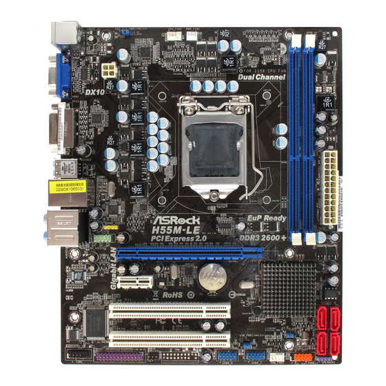
Page 11: Motherboard Layout
COM Port Header (COM1) 16Mb SPI Flash PCI Slots (PCI1-2) Secondary SATAII Connector (SATAII_2, Red) PCI Express 2.0 x1 Slot (PCIE2, White) Primary SATAII Connector (SATAII_1, Red) PCI Express 2.0 x16 Slot (PCIE1, Blue) Third SATAII Connector (SATAII_3, Red) Front Panel Audio Header…
-
Page 12: I/O Panel
Line In (Light Blue) PS/2 Keyboard Port (Purple) ** 7 Front Speaker (Lime) * There are two LED next to the LAN port. Please refer to the table below for the LAN port LED indications. LAN Port LED Indications ACT/LINK…
-
Page 13
To enable Multi-Streaming function, you need to connect a front panel audio cable to the front panel audio header. After restarting your computer, you will find “VIA HD Audio Deck” tool on your system. Please follow below instructions according to the OS you install. -
Page 14: Installation
Chapter 2: Installation Chapter 2: Installation This is a Micro ATX form factor (9.6″ x 8.0″, 24.4 x 20.3 cm) motherboard. Before you install the motherboard, study the configuration of your chassis to ensure that the motherboard fits into it.
-
Page 15: Cpu Installation
Before you insert the 1156-Pin CPU into the socket, please check if the CPU surface is unclean or if there is any bent pin on the socket. Do not force to insert the CPU into the socket if above situation is found.
-
Page 16
1156-Pin CPU For proper inserting, please ensure to match the two orientation key notches of the CPU with the two alignment keys of the socket. Step 3-3. Carefully place the CPU into the socket by using a purely vertical motion. -
Page 17: Installation Of Heatsink And Cpu Fan
CPU and the heatsink to improve heat dissipation. Ensure that the CPU and the heatsink are securely fastened and in good contact with each other. Then connect the CPU fan to the CPU_FAN connector (CPU_FAN1, see page 11, No.
-
Page 18: Installation Of Memory Modules (Dimm)
DIMMs or the system components. Step 1. Unlock a DIMM slot by pressing the retaining clips outward. Step 2. Align a DIMM on the slot such that the notch on the DIMM matches the break on the slot. notch break…
-
Page 19: Expansion Slots (Pci And Pci Express Slots)
PCIE1 (PCIE x16 slot; Blue) is used for PCI Express x16 lane width graphics cards. PCIE2 (PCIE x1 slot; White) is used for PCI Express cards with x1 lane width cards, such as Gigabit LAN card, SATA2 card, etc. Installing an expansion card…
-
Page 20: Jumpers Setup
After waiting for 15 seconds, use a jumper cap to short pin2 and pin3 on CLRCMOS1 for 5 seconds. However, please do not clear the CMOS right after you update the BIOS.
-
Page 21: Onboard Headers And Connectors
2.8 Onboard Headers and Connectors Onboard headers and connectors are NOT jumpers. Do NOT place jumper caps over these headers and connectors. Placing jumper caps over the headers and connectors will cause permanent damage of the motherboard! Serial ATAII Connectors…
-
Page 22
HDA to function correctly. Please follow the instruction in our manual and chassis manual to install your system. 2. If you use AC’97 audio panel, please install it to the front panel audio header as below: A. -
Page 23
Though this motherboard provides 4-Pin CPU fan (Quiet Fan) support, the 3-Pin CPU fan still can work successfully even without the fan speed control function. If you plan to connect the 3-Pin CPU fan to the CPU fan connector on this motherboard, please connect it to Pin 1-3. -
Page 24
HDMI_SPDIF Header HDMI_SPDIF header, providing SPDIF audio output to HDMI VGA (3-pin HDMI_SPDIF1) card, allows the system to (see p.11 No. 29) SPDIFOUT connect HDMI Digital TV/ projector/LCD devices. Please connect the HDMI_SPDIF connector of HDMI VGA card to this header. -
Page 25: Hdmi_Spdif Header Connection Guide
HDMI (High-Definition Multi-media Interface) is an all-digital audio/video specification, which provides an interface between any compatible digital audio/ video source, such as a set-top box, DVD player, A/V receiver and a compatible digital audio or video monitor, such as a digital television (DTV). A complete HDMI system requires a HDMI VGA card and a HDMI ready motherboard with a HDMI_SPDIF header.
-
Page 26: Sataii Hard Disk Setup Guide
Before installing SATAII hard disk to your computer, please carefully read below SATAII hard disk setup guide. Some default setting of SATAII hard disks may not be at SATAII mode, which operate with the best performance. In order to enable SATAII function, please follow the below instruction with different vendors to correctly adjust your SATAII hard disk to SATAII mode in advance;…
-
Page 27: Installation
STEP 2: Connect the SATA power cable to the SATA / SATAII hard disk. STEP 3: Connect one end of the SATA data cable to the motherboard’s SATAII connector. STEP 4: Connect the other end of the SATA data cable to the SATA / SATAII hard disk. 2.12 Hot Plug F 2.12 Hot Plug F…
-
Page 28: Guide
SATA / SATAII driver is available on our support website: www.asrock.com 4. Make sure to use the SATA power cable & data cable, which are from our motherboard package. 5. Please follow below instructions step by step to reduce the risk of HDD crash…
-
Page 29
Please do follow below instruction sequence to process the Hot Unplug, improper procedure will cause the SATA / SATAII HDD damage and data loss. Step 1 Unplug SATA data cable from SATA / SATAII HDD side. Unplug SATA 15-pin power cable connector (Black) from SATA / SATAII HDD side. Step 2… -
Page 30: Driver Installation Guide
2.14 Driver Installation Guide To install the drivers to your system, please insert the support CD to your optical drive first. Then, the drivers compatible to your system can be auto-detected and listed on the support CD driver page. Please follow the order from up to bottom side to install those required drivers.
-
Page 31: Untied Overclocking Technology
Untied Overclocking function, please enter “Overclock Mode” option of BIOS setup to set the selection from [Auto] to [Manual]. Therefore, CPU FSB is untied during overclocking, but PCI / PCIE buses are in the fixed mode so that FSB can operate under a more stable overclocking environment.
-
Page 32: Bios Setup Utility
The BIOS FWH chip on the motherboard stores the BIOS SETUP UTILITY. You may run the BIOS SETUP UTILITY when you start up the computer. Please press <F2> or <Del> during the Power-On-Self-Test (POST) to enter the BIOS SETUP UTILITY, otherwise, POST will continue with its test routines.
-
Page 33: Navigation Keys
3 . 2 3 . 2 3 . 2 Main Screen Main Screen Main Screen When you enter the BIOS SETUP UTILITY, the Main screen will appear and display the system overview. BIOS SETUP UTILITY OC Tweaker Advanced H/W Monitor…
-
Page 34: Oc Tweaker Screen
® ® Load CPU EZ OC Setting You can use this option to load CPU EZ overclocking setting. Please note that overclocing may cause damage to your CPU and motherboard. It should be done at your own risk and expense.
-
Page 35
Good Night LED Enable this option to turn off Power LED and Lan LED when the system is power on. The keyboard LED will also be turned off in S1, S3 and S4 state. The default value is [Disabled]. Overclock Mode Use this to select Overclock Mode. -
Page 36
Exit v02.54 (C) Copyright 1985-2005, American Megatrends, Inc. DRAM tCL Use this item to adjust the means of memory accessing. Configuration options : [Auto], [6] to [11]. DRAM tRCD This controls the number of DRAM clocks for TRCD. Configuration options: [Auto], [3] to [15]. -
Page 37
IGD VID Use this to select onboard VGA VID. The default value is [Auto]. Would you like to save current setting user defaults? In this option, you are allowed to load and save three user defaults according to your own requirements. -
Page 38: Advanced Screen
. Just launch ® this tool and save the new BIOS file to your USB flash drive, floppy disk or hard drive, then you can update your BIOS only in a few clicks without preparing an additional floppy diskette or other complicated flash utility.
-
Page 39: Cpu Configuration
[Enabled] v02.54 (C) Copyright 1985-2005, American Megatrends, Inc. CPU Ratio Setting If the ratio status is unlocked, you will find this item appear to allow you changing the ratio value of this motherboard. Enhance Halt State All processors support the Halt State (C1). The C1 state is supported through the native processor instructions HLT and MWAIT and requires no hardware support from the chipset.
-
Page 40
Intel (R) C-STATE tech. is achieved by making the power and thermal con- trol unit part of the core logic and not part of the chipset as before. Migration of the power and thermal management flow into the processor allows us… -
Page 41: Chipset Configuration
DVMT/FIXED Memory You are allowed to adjust the shared memory size in this item if you set DVMT Mode Select as [DVMT Mode]. Configuration options: [128MB], [256MB] and [Maximum DVMT]. The option [Maximum DVMT] only appears when you adopt the memory module with 1024MB or above.
-
Page 42: Acpi Configuration
Use this item to enable or disable Ring-In signals to turn on the system from the power-soft-off mode. PCI Devices Power On Use this item to enable or disable PCI devices to turn on the system from the power-soft-off mode. PS/2 Keyboard Power On Use this item to enable or disable PS/2 keyboard to turn on the system from the power-soft-off mode.
-
Page 43: Storage Configuration
RTC Alarm Power On Use this item to enable or disable RTC (Real Time Clock) to power on the system. ACPI HPET Table Use this item to enable or disable ACPI HPET Table. The default value is [Disabled]. Please set this option to [Enabled] if you plan to use this…
-
Page 44
[ARMD]: This is used for IDE ARMD (ATAPI Removable Media Device), such as MO. LBA/Large Mode Use this item to select the LBA/Large mode for a hard disk > 512 MB under DOS and Windows; for Netware and UNIX user, select [Disabled] to disable the LBA/Large mode. -
Page 45: Pcipnp Configuration
Reporting Technology) feature. Configuration options: [Disabled], [Auto], [Enabled]. 32-Bit Data Transfer Use this item to enable 32-bit access to maximize the IDE hard disk data transfer rate. 3 . 4 . 5 3 . 4 . 5 PCIPnP Configuration 3 .
-
Page 46: Super Io Configuration
(C) Copyright 1985-2003, American Megatrends, Inc. Serial Port Address Use this item to set the address for the onboard serial port or disable it. Configuration options: [Disabled], [3F8 / IRQ4], [2F8 / IRQ3], [3E8 / IRQ4], [2E8 / IRQ3].
-
Page 47: Usb Configuration
[Enabled] — Enables support for legacy USB. [Auto] — Enables legacy support if USB devices are connected. [Disabled] — USB devices are not allowed to use under legacy OS and BIOS setup when [Disabled] is selected. If you have USB compatibility issue, it is recommended to select [Disabled] to enter OS.
-
Page 48: Hardware Health Event Monitoring Screen
3 . 5 Hardware Health Event Monitoring Screen In this section, it allows you to monitor the status of the hardware on your system, including the parameters of the CPU temperature, motherboard temperature, CPU fan speed, chassis fan speed, and the critical voltage.
-
Page 49: Boot Screen
Boot Screen Boot Screen 3 . 6 3 . 6 Boot Screen In this section, it will display the available devices on your system for you to configure the boot settings and the boot priority. BIOS SETUP UTILITY Main OC Tweaker…
-
Page 50: Security Screen
Security Screen 3 . 7 3 . 7 Security Screen In this section, you may set or change the supervisor/user password for the system. For the user password, you may also clear it. BIOS SETUP UTILITY Main OC Tweaker Advanced…
-
Page 51: Exit Screen
When you select this option, it will pop-out the following message, “Discard changes?” Select [OK] to discard all changes. Load BIOS Defaults Load BIOS default values for all the setup questions. F9 key can be used for this operation. Load Performance Setup Default (IDE/SATA) This performance setup default may not be compatible with all system configurations.
-
Page 52: Install Operating System
4 . 2 . 4 4 . 2 . 4 C o n t a c t I n f o r m a t i o n C o n t a c t I n f o r m a t i o n…
-
Драйверы
22
-
Инструкции по эксплуатации
2

Asrock H55M-LE инструкция по эксплуатации
(52 страницы)
- Языки:Английский
-
Тип:
PDF -
Размер:
770.53 KB
Просмотр

Asrock H55M-LE инструкция по эксплуатации
(181 страница)
-
Тип:
PDF -
Размер:
5.18 MB
Просмотр
На NoDevice можно скачать инструкцию по эксплуатации для Asrock H55M-LE. Руководство пользователя необходимо для ознакомления с правилами установки и эксплуатации Asrock H55M-LE. Инструкции по использованию помогут правильно настроить Asrock H55M-LE, исправить ошибки и выявить неполадки.
-
Страница 1
1 1 1 1 1 H55M-LE User Ma nual V ersion 1.0 Published January 2010 Copyright©2010 ASRock INC. All rights reserved.[…]
-
Страница 2
2 2 2 2 2 Copyright Notice: Copyright Notice: Copyright Notice: Copyright Notice: Copyright Notice: No part of this manual may be reproduced, transcribed, transmitted, or translated in any language, in any form or by any means, except duplication of documentation by the purcha ser for ba ckup purpose, without written consent of ASRock Inc. Products[…]
-
Страница 3
3 3 3 3 3 Contents Contents Contents Contents Contents 1 Introduction 1 Introduction 1 Introduction 1 Introduction 1 Introduction …………………………………………… …………………………………………… …………………………………………… …………………………………………… …………[…]
-
Страница 4
4 4 4 4 4 3.4.5 PCIPnP Configuration ……………………………………. 45 3.4.6 Super IO Configuration …………………………………. 46 3.4.7 USB Configuration ……………………………………….. 4 7 3.5 Hardware Health Event Monitoring Screen ……………… 48 3.6 Boot Screen ……………………………..[…]
-
Страница 5
5 5 5 5 5 Chapter 1: Introduction Chapter 1: Introduction Chapter 1: Introduction Chapter 1: Introduction Chapter 1: Introduction Tha nk you for purcha sing ASRock H55M-LE motherboard, a relia ble motherboard produced under ASRock’s consistently stringent quality control. It delivers excellent performa nce with robust design conf orming to ASRock[…]
-
Страница 6
6 6 6 6 6 1.2 1.2 1.2 1.2 1.2 Specifications Specifications Specifications Specifications Specifications Platform — Micro A TX Form Factor: 9.6-in x 8.0-in, 24.4 cm x 20.3 cm — Solid Ca pa citor for CPU power CPU — Supports Intel ® Core TM i7 / i5 / i3 a nd Pentium ® G6950 Processors in LGA1 156 Pa ckage — Supports Intel ® Turbo Boost T echnolog[…]
-
Страница 7
7 7 7 7 7 Rear Panel I/O I/O Panel — 1 x PS/2 Keyboard Port — 1 x V GA/D-Sub Port — 1 x V GA/D VI-D Port — 6 x Ready-to-Use USB 2.0 Ports — 1 x RJ-45 LAN Port with LED (ACT/LINK LED and SPEED LED) — HD Audio Jack: Side Spe aker/Rear Spe a ker/Central/Ba ss/ Line in/Front Speaker/Microphone (see CAUTION 8 ) Connector — 4 x SA T AII 3.0Gb/s connector[…]
-
Страница 8
8 8 8 8 8 W ARNING Plea se realize that there is a certain risk involved with overclocking, including adjusting the setting in the BIOS, a pplying U ntied Overclocking T e chnology , or using the third- party overclocking tools. Overclocking may affect your system stability, or even cause da mage to the components and device s of your system. It sh[…]
-
Страница 9
9 9 9 9 9 CAUTION! 1. Intel ® Core TM i3 and Pentium ® G6950 processors do not support Intel ® Turbo Boost T echnology . 2. About the setting of “Hyper Thre ading T echnology”, plea se check page 39. 3. This motherboard supports U ntied Overclocking T e chnology . Plea se read “U ntied Overclocking T echnology” on page 31 for details. 4.[…]
-
Страница 10
10 10 10 10 10 13. ASRock In stant Fla sh is a BIOS fla sh utility embedded in Fla sh ROM. This convenient BIOS update tool allows you to update system BIOS without entering operating systems first like MS-DOS or Windows ® . With this utility, you can press <F6> key during the POST or press <F2> key to BIOS setup menu to a ccess ASRock[…]
-
Страница 11
11 11 11 11 11 1.3 Motherboard Layout 1.3 Motherboard Layout 1.3 Motherboard Layout 1.3 Motherboard Layout 1.3 Motherboard Layout Intel H55 DDR3_A1 (64 bit, 240-pin module) DDR3_B1 (64 bit, 240-pin module) 20.3cm (8.0 in) 24.4cm (9.6 in) A TXPWR1 PWR_FAN1 CPU_FAN1 SAT AII_4 SAT AII_2 SAT AII_3 SAT AII_1 ATX12V1 PS2_USB_PWR1 1 16Mb BIOS LAN PHY HD_A[…]
-
Страница 12
12 12 12 12 12 1.4 1.4 1.4 1.4 1.4 I/O Panel I/O Panel I/O Panel I/O Panel I/O Panel LAN Port ACT/LINK LED SPEED LED * There are two LED next to the LAN port. Plea se refer to the table below for the LAN port LED indications. LAN Port LED Indications Activity/Link LE D SPEED LED Status Description Status Description Off No Link Off 10Mbps connectio[…]
-
Страница 13
13 13 13 13 13 T o enable Multi-Stre a ming function, you need to connect a front panel audio ca ble to the front panel audio header. After restarting your computer, you will find “VIA HD Audio Deck” tool on your system. Ple a se follow below instruction s according to the OS you in stall. For Windows ® XP / XP 64-bit OS: Plea se click “VIA […]
-
Страница 14
14 14 14 14 14 Chapter 2: Installation Chapter 2: Installation Chapter 2: Installation Chapter 2: Installation Chapter 2: Installation This is a Micro A TX form fa ctor (9.6″ x 8.0″, 24.4 x 20.3 cm) motherboard. Before you install the motherboard, study the configuration of your cha ssis to ensure that the motherboard fits into it. Make s[…]
-
Страница 15
15 15 15 15 15 2.3 CPU Installation 2.3 CPU Installation 2.3 CPU Installation 2.3 CPU Installation 2.3 CPU Installation For the installation of Intel 1 156-Pin CPU, plea se follow the steps below . Before you insert the 1 156-Pin CPU into the socket, plea se check if the CPU surface is unclean or if there is any bent pin on the socket. Do not force[…]
-
Страница 16
16 16 16 16 16 black line Pin1 alignment key alignment key Pin1 1156-Pin CPU 1156-Pin Socket Step 3. In sert the 1 156-Pin CPU: Step 3-1. Hold the CPU by the edge where is marked with bla ck line. Step 3-2. Orient the CPU with IHS (Integrated Heat Sink) up. Locate Pin1 a nd the two ori- entation key notches. For proper inserting, ple a se ensure to[…]
-
Страница 17
17 17 17 17 17 2.4 2.4 2.4 2.4 2.4 Installation of CPU Fan and Heatsink Installation of CPU Fan and Heatsink Installation of CPU Fan and Heatsink Installation of CPU Fan and Heatsink Installation of CPU Fan and Heatsink This motherboard is equipped with 1 156-Pin socket that supports Intel 1 156-Pin CPU. Plea se adopt the type of heatsink a nd cool[…]
-
Страница 18
18 18 18 18 18 2.5 Installation of Memory Modules (DIMM) 2.5 Installation of Memory Modules (DIMM) 2.5 Installation of Memory Modules (DIMM) 2.5 Installation of Memory Modules (DIMM) 2.5 Installation of Memory Modules (DIMM) H55M-LE motherboard provides two 240-pin DDR3 (Double Data Rate 3) DIMM slots, a nd supports Dual Channel Memory T echnology […]
-
Страница 19
19 19 19 19 19 2.6 Expansion Slots (PCI and PCI Express Slots) 2.6 Expansion Slots (PCI and PCI Express Slots) 2.6 Expansion Slots (PCI and PCI Express Slots) 2.6 Expansion Slots (PCI and PCI Express Slots) 2.6 Expansion Slots (PCI and PCI Express Slots) There are 2 PCI slots and 2 PCI Express slots on this motherboard. PCI slot: PCI slot is used t[…]
-
Страница 20
20 20 20 20 20 +5V 1_2 +5VSB 2_3 Clear CMOS 2_3 1_2 Default If you clear the CMOS, the ca se open may be detected. Plea se adjust the BIOS option “Clear Status” to clear the re cord of previous cha ssis intrusion status. 2.7 Jumpers Setup 2.7 Jumpers Setup 2.7 Jumpers Setup 2.7 Jumpers Setup 2.7 Jumpers Setup The illustration shows how jumpers […]
-
Страница 21
21 21 21 21 21 Print Port Header This is a n interfa ce f or print (25-pin LPT1) port cable that allows (see p.1 1 No. 23) convenient connection of printer devices. 1 AFD# ERROR# PINIT# GND SLIN# STB# SPD0 SPD1 SPD2 SPD3 SPD4 SPD5 SPD6 SPD7 ACK# BUSY PE SLCT USB 2.0 Headers Besides six default USB 2.0 (9-pin USB8_9) ports on the I/O panel, there ar[…]
-
Страница 22
22 22 22 22 22 GND PWRBTN# PLED- PLED+ DUMMY RESET# GND HDLED+ HDLED- 1 System Panel Header This header a ccommodates (9-pin P ANEL1) several system front pa nel (see p.1 1 No. 15) functions. Cha ssis Speaker He ader Plea se connect the cha ssis (4-pin SPEAKER 1) speaker to this header. (see p.1 1 No. 14) +5V DUMMY DUMMY SPEAKER 1 Infrared Module H[…]
-
Страница 23
23 23 23 23 23 20-Pin A TX Power Supply Installation Though this motherboard provides 24-pin A TX power connector , it ca n still work if you adopt a tradition al 20-pin A TX power supply . T o use the 20-pin A TX power supply , plea se plug your power supply along with Pin 1 a nd Pin 13. 12 1 24 13 Though this motherboard provides 4-Pin CPU fan (Q[…]
-
Страница 24
24 24 24 24 24 HDMI_SPDIF Cable P l ea s e connect the bla ck end (A) (Optional) of HDMI_SPDIF cable to the HDMI_SPDIF header on the motherboard. Then connect the white end (B or C) of HDMI_SPDIF cable to the HDMI_SPDIF connector of HDMI V GA card. A. bla ck end B. white end (2-pin) C. white end (3-pin) C B GND +5V SPDIFOUT blue black blue black GN[…]
-
Страница 25
25 25 25 25 25 2.9 HDMI_SPDIF Header Connection Guide 2.9 HDMI_SPDIF Header Connection Guide 2.9 HDMI_SPDIF Header Connection Guide 2.9 HDMI_SPDIF Header Connection Guide 2.9 HDMI_SPDIF Header Connection Guide HDMI (High-Definition Multi-medi a Interfa ce) is an all-digital audio/video specification, which provides a n interfa ce between a ny compa[…]
-
Страница 26
26 26 26 26 26 2.10 SA 2.10 SA 2.10 SA 2.10 SA 2.10 SA T T T T T AII Hard Disk Setup Guide AII Hard Disk Setup Guide AII Hard Disk Setup Guide AII Hard Disk Setup Guide AII Hard Disk Setup Guide Before installing SA T AII hard disk to your computer , plea se carefully read below SA T AII hard disk setup guide. Some default setting of SA T AII hard […]
-
Страница 27
27 27 27 27 27 2.12 Hot Plug F 2.12 Hot Plug F 2.12 Hot Plug F 2.12 Hot Plug F 2.12 Hot Plug F unction for SA unction for SA unction for SA unction for SA unction for SA T T T T T A / SA A / SA A / SA A / SA A / SA T T T T T AII HDDs AII HDDs AII HDDs AII HDDs AII HDDs This motherboard supports Hot Plug function for SA T A / SA T AII in AHCI mode. […]
-
Страница 28
28 28 28 28 28 Caution 1. Without SA T A 15-pin power connector interfa ce, the SA T A / SA T AII Hot Plug cannot be processed. 2. Even some SA T A / SA T AII HDDs provide both SA T A 15-pin power connector a nd IDE 1×4-pin conventional power connector interfa ces, the IDE 1×4-pin conventional power connector interfa ce is definitely not able to su[…]
-
Страница 29
29 29 29 29 29 How to Hot Plug a SA T A / SA T AII HDD: Points of attention, before you process the Hot Plug: Plea se do follow below instruction sequence to proce ss the Hot Plug, improper procedure will cause the SA T A / SA T AII HDD da mage a nd data loss. Connect SA T A data ca ble to the motherboard’s SA T AII connector . Connect SA T A 15-[…]
-
Страница 30
30 30 30 30 30 2.14 2.14 2.14 2.14 2.14 Driver Installation Guide Driver Installation Guide Driver Installation Guide Driver Installation Guide Driver Installation Guide T o install the drivers to your system, plea se insert the support CD to your optical drive first. Then, the drivers compatible to your system can be auto-detected and listed on th[…]
-
Страница 31
31 31 31 31 31 Using SA T A / SA T AII HDDs without NCQ function (IDE mode) STEP 1: Set up BIOS. A. Enter BIOS SETUP UTILITY Advanced screen Storage Conf iguration. B. Set the option “SA T A Operation Mode” to [IDE]. STEP 2: Install Windows ® 7 / 7 64-bit / Vista TM / Vista TM 64-bit OS on your system. 2.16 2.16 2.16 2.16 2.16 Untied Overclock[…]
-
Страница 32
32 32 32 32 32 Chapter 3: BIOS SETUP UTILITY Chapter 3: BIOS SETUP UTILITY Chapter 3: BIOS SETUP UTILITY Chapter 3: BIOS SETUP UTILITY Chapter 3: BIOS SETUP UTILITY 3.1 3.1 3.1 3.1 3.1 Introduction Introduction Introduction Introduction Introduction This section explains how to use the BIOS SETUP UTILITY to configure your system. The BIOS FWH chip […]
-
Страница 33
33 33 33 33 33 BIOS SETUP UTILITY Main OC T weaker H/W Monitor Boot Security Exit Advanced System Overview System Time System Date [ :00:09] [Fri 01/22/2010] Use [Enter], [T AB] or [SHIFT -T AB] to select a field. Use [+] or [-] to configure system Time. Select Screen Select Item +- Change Field T ab Select Field F1 General Help F9 Load Defaults F1[…]
-
Страница 34
34 34 34 34 34 3.3 3.3 3.3 3.3 3.3 OC T OC T OC T OC T OC T weak weak weak weak weak er Screen er Screen er Screen er Screen er Screen In the OC T wea ker screen, you can set up overclocking fe atures. BIOS SETUP UTILITY Main Advanced H/W Monitor Boot Security Exit Overclocking may cause damage to your CPU and motherboard. It should be done at your[…]
-
Страница 35
35 35 35 35 35 Good Night LED Enable this option to turn off Power LED and Lan LED when the system is power on. The keyboard LED will also be turned off in S1, S3 and S4 state. The default value is [Disabled]. Overclock Mode Use this to select Overclock Mode. Configuration options: [Auto], [Manual] a nd [Optimized]. The default value is [Auto]. If […]
-
Страница 36
36 36 36 36 36 DRAM Timing Control Use this item to control DRAM T iming. DRAM tCL Use this item to a djust the mea ns of memory a ccessing. Configuration options : [Auto], [6] to [1 1]. DRAM tRCD This controls the number of DRAM clocks f or TRCD. Configuration options: [Auto], [3] to [15]. DRAM tRP This controls the number of DRAM clocks for TRP .[…]
-
Страница 37
37 37 37 37 37 DRAM tF A W This controls the number of DRAM clocks fo r TF AW . Configuration options: [Auto], [1] to [63]. DRAM Command Rate Use this item to a djust DRAM Comma nd Rate. Configuration options : [Auto], [1] and [2]. CPU V oltage Use this to select CPU V oltage. Configuration options: [Auto], [M a nual] a nd [Overdrive Offset]. The d[…]
-
Страница 38
38 38 38 38 38 Setting wrong values in this section may cause the system to malfunction. 3.4 3.4 3.4 3.4 3.4 Advanced Screen Advanced Screen Advanced Screen Advanced Screen Advanced Screen In this section, you may set the configurations for the following items: CPU Configuration, Chipset Conf iguration, ACPI Configuration, Storage Configuration, PC[…]
-
Страница 39
39 39 39 39 39 3.4.1 3.4.1 3.4.1 3.4.1 3.4.1 CPU Configuration CPU Configuration CPU Configuration CPU Configuration CPU Configuration CPU Ratio Setting If the ratio status is unlocked, you will find this item a ppear to allow you changing the ratio value of this motherboard. Enhance Halt State All processors support the Halt State (C1). The C1 sta[…]
-
Страница 40
40 40 40 40 40 Intel (R) T urboMode tech Use this item to en able or disable Intel (R) T urbo Boost T echnology . Turbo mode allows processor core s to run fa ster than marked frequency in specific condition. The default value is [Enabled]. Intel (R) C-ST A TE tech. Intel (R) C-ST A TE tech. is a chieved by ma king the power a nd thermal con- trol […]
-
Страница 41
41 41 41 41 41 BIOS SETUP UTILITY Chipset Settings Select Screen Select Item +- Change Option F1 General Help F9 Load Defaults F10 Save and Exit ESC Exit v02.54 (C) Copyright 1985-2005, American Megatrends, Inc. Advanced Select Screen Select Item +- Change Option F1 General Help F9 Load Defaults F10 Save and Exit ESC Exit Primary Graphics Adapter [[…]
-
Страница 42
42 42 42 42 42 BIOS SETUP UTILITY ACPI Configuration Select auto-detect or disable the STR feature. Select Screen Select Item +- Change Option F1 General Help F9 Load Defaults F10 Save and Exit ESC Exit v02.54 (C) Copyright 1985-2005, American Megatrends, Inc. Advanced Suspend T o RAM Restore on AC/Power Loss Ring-In Power On PCI Devices Power On P[…]
-
Страница 43
43 43 43 43 43 BIOS SETUP UTILITY Storage Configuration v02.54 (C) Copyright 1985-2003, American Megatrends, Inc. Advanced SA T A Operation Mode SA T AII_1 SA T AII_2 SA T AII_3 SA T AII_4 [IDE] [Hard Disk] [Not Detected] [Not Detected] [Not Detected] Select Screen Select Item +- Change Option F1 General Help F9 Load Defaults F10 Save and Exit ESC […]
-
Страница 44
44 44 44 44 44 [CD/D V D]: This is used for IDE CD/D V D drives. [ARMD]: This is used f or IDE ARMD (A T API Removable Medi a Device), such a s MO. LBA/Large Mode Use this item to select the LBA/Large mode for a hard disk > 512 MB under DOS a nd Windows; f or Netware a nd UNIX user , select [Disabled] to disable the LBA/Large mode. Block (Multi-[…]
-
Страница 45
45 45 45 45 45 BIOS SETUP UTILITY Advanced PCI / PnP Settings V a l u ei nu n i t so fP C I clocks for PCI device latency timer regi ste r . Select Screen Select Item +- Change Option F1 General Help F9 Load Defaults F10 Save and Exit ESC Exit v02.54 (C) Copyright 1985-2005, American Megatrends, Inc. PCI Latency Timer PCI IDE BusMaster [64] [Enable[…]
-
Страница 46
46 46 46 46 46 3.4.6 3.4.6 3.4.6 3.4.6 3.4.6 Super IO Configuration Super IO Configuration Super IO Configuration Super IO Configuration Super IO Configuration Serial Port Address Use this item to set the address for the onboard serial port or disable it. Configuration options: [Disabled], [3F8 / IRQ4], [2F8 / IRQ3], [3E8 / IRQ4], [2E8 / IRQ3]. Inf[…]
-
Страница 47
47 47 47 47 47 3.4.7 3.4.7 3.4.7 3.4.7 3.4.7 USB Configuration USB Configuration USB Configuration USB Configuration USB Configuration USB Controller Use this item to enable or disable the use of USB controller. Legacy USB Support Use this option to select lega cy support for USB device s. There are f our configuration options: [Ena bled], [Auto], […]
-
Страница 48
48 48 48 48 48 BIOS SETUP UTILITY Hardware Health Event Monitoring Select Screen Select Item F1 General Help F9 Load Defaults F10 Save and Exit ESC Exit v02.54 (C) Copyright 1985-2003, American Megatrends, Inc. CPU T emperature M/B T emperature CPU Fan Speed Chassis Fan Speed Power Fan Speed Vcore + 3.30V + 5.00V + 12.00V : 3 7C/9 8F :N / A : 3 1C/[…]
-
Страница 49
49 49 49 49 49 3.6.1 3.6.1 3.6.1 3.6.1 3.6.1 Boot Settings Configuration Boot Settings Configuration Boot Settings Configuration Boot Settings Configuration Boot Settings Configuration Full Screen Logo Use this item to enable or disable OEM Logo. The default value is [Enabled]. AddOn ROM Display Use this option to adjust AddOn ROM Display . If you […]
-
Страница 50
50 50 50 50 50 BIOS SETUP UTILITY Main OC T weaker Advanced H/W Monitor Boot Exit Install or Change the password. Select Screen Select Item Enter Change F1 General Help F10 Save and Exit ESC Exit F9 Load Defaults v02.54 (C) Copyright 1985-2005, American Megatrends, Inc. Security Change Supervisor Password Change User Password Security Settings Supe[…]
-
Страница 51
51 51 51 51 51 BIOS SETUP UTILITY Main OC T weaker Advanced H/W Monitor Boot Security Exit system setup after saving the changes. F 1 0k e yc a nb eu s e d for this operation. Select Screen Select Item Enter Go to Sub Screen F1 General Help F10 Save and Exit ESC Exit F9 Load Defaults v02.54 (C) Copyright 1985-2005, American Megatrends, Inc. Exit Sa[…]
-
Страница 52
52 52 52 52 52 Chapter 4: Sof Chapter 4: Sof Chapter 4: Sof Chapter 4: Sof Chapter 4: Sof tware Suppor tware Suppor tware Suppor tware Suppor tware Suppor t t t t t 4.1 4.1 4.1 4.1 4.1 Install Operating System Install Operating System Install Operating System Install Operating System Install Operating System This motherboard supports various Micros[…]
-
Asrock H55M-LE — page 1
1 1 1 1 1 H55M-LE User Ma nual V ersion 1.0 Published January 2010 Copyright©2010 ASRock INC. All rights reserved. …
-
Asrock H55M-LE — page 2
2 2 2 2 2 Copyright Notice: Copyright Notice: Copyright Notice: Copyright Notice: Copyright Notice: No part of this manual may be reproduced, transcribed, transmitted, or translated in any language, in any form or by any means, except duplication of documentation by the purcha ser for ba ckup purpose, without written consent of ASRock Inc. Products …
-
Asrock H55M-LE — page 3
3 3 3 3 3 Contents Contents Contents Contents Contents 1 Introduction 1 Introduction 1 Introduction 1 Introduction 1 Introduction …………………………………………… …………………………………………… …………………………………………… …………………………………………… ………… …
-
Asrock H55M-LE — page 4
4 4 4 4 4 3.4.5 PCIPnP Configuration ……………………………………. 45 3.4.6 Super IO Configuration …………………………………. 46 3.4.7 USB Configuration ……………………………………….. 4 7 3.5 Hardware Health Event Monitoring Screen ……………… 48 3.6 Boot Screen …………………………….. …
-
Asrock H55M-LE — page 5
5 5 5 5 5 Chapter 1: Introduction Chapter 1: Introduction Chapter 1: Introduction Chapter 1: Introduction Chapter 1: Introduction Tha nk you for purcha sing ASRock H55M-LE motherboard, a relia ble motherboard produced under ASRock’s consistently stringent quality control. It delivers excellent performa nce with robust design conf orming to ASRock …
-
Asrock H55M-LE — page 6
6 6 6 6 6 1.2 1.2 1.2 1.2 1.2 Specifications Specifications Specifications Specifications Specifications Platform — Micro A TX Form Factor: 9.6-in x 8.0-in, 24.4 cm x 20.3 cm — Solid Ca pa citor for CPU power CPU — Supports Intel ® Core TM i7 / i5 / i3 a nd Pentium ® G6950 Processors in LGA1 156 Pa ckage — Supports Intel ® Turbo Boost T echnolog …
-
Asrock H55M-LE — page 7
7 7 7 7 7 Rear Panel I/O I/O Panel — 1 x PS/2 Keyboard Port — 1 x V GA/D-Sub Port — 1 x V GA/D VI-D Port — 6 x Ready-to-Use USB 2.0 Ports — 1 x RJ-45 LAN Port with LED (ACT/LINK LED and SPEED LED) — HD Audio Jack: Side Spe aker/Rear Spe a ker/Central/Ba ss/ Line in/Front Speaker/Microphone (see CAUTION 8 ) Connector — 4 x SA T AII 3.0Gb/s connector …
-
Asrock H55M-LE — page 8
8 8 8 8 8 W ARNING Plea se realize that there is a certain risk involved with overclocking, including adjusting the setting in the BIOS, a pplying U ntied Overclocking T e chnology , or using the third- party overclocking tools. Overclocking may affect your system stability, or even cause da mage to the components and device s of your system. It sh …
-
Asrock H55M-LE — page 9
9 9 9 9 9 CAUTION! 1. Intel ® Core TM i3 and Pentium ® G6950 processors do not support Intel ® Turbo Boost T echnology . 2. About the setting of “Hyper Thre ading T echnology”, plea se check page 39. 3. This motherboard supports U ntied Overclocking T e chnology . Plea se read “U ntied Overclocking T echnology” on page 31 for details. 4. …
-
Asrock H55M-LE — page 10
10 10 10 10 10 13. ASRock In stant Fla sh is a BIOS fla sh utility embedded in Fla sh ROM. This convenient BIOS update tool allows you to update system BIOS without entering operating systems first like MS-DOS or Windows ® . With this utility, you can press <F6> key during the POST or press <F2> key to BIOS setup menu to a ccess ASRock …
-
Asrock H55M-LE — page 11
11 11 11 11 11 1.3 Motherboard Layout 1.3 Motherboard Layout 1.3 Motherboard Layout 1.3 Motherboard Layout 1.3 Motherboard Layout Intel H55 DDR3_A1 (64 bit, 240-pin module) DDR3_B1 (64 bit, 240-pin module) 20.3cm (8.0 in) 24.4cm (9.6 in) A TXPWR1 PWR_FAN1 CPU_FAN1 SAT AII_4 SAT AII_2 SAT AII_3 SAT AII_1 ATX12V1 PS2_USB_PWR1 1 16Mb BIOS LAN PHY HD_A …
-
Asrock H55M-LE — page 12
12 12 12 12 12 1.4 1.4 1.4 1.4 1.4 I/O Panel I/O Panel I/O Panel I/O Panel I/O Panel LAN Port ACT/LINK LED SPEED LED * There are two LED next to the LAN port. Plea se refer to the table below for the LAN port LED indications. LAN Port LED Indications Activity/Link LE D SPEED LED Status Description Status Description Off No Link Off 10Mbps connectio …
-
Asrock H55M-LE — page 13
13 13 13 13 13 T o enable Multi-Stre a ming function, you need to connect a front panel audio ca ble to the front panel audio header. After restarting your computer, you will find “VIA HD Audio Deck” tool on your system. Ple a se follow below instruction s according to the OS you in stall. For Windows ® XP / XP 64-bit OS: Plea se click “VIA …
-
Asrock H55M-LE — page 14
14 14 14 14 14 Chapter 2: Installation Chapter 2: Installation Chapter 2: Installation Chapter 2: Installation Chapter 2: Installation This is a Micro A TX form fa ctor (9.6″ x 8.0″, 24.4 x 20.3 cm) motherboard. Before you install the motherboard, study the configuration of your cha ssis to ensure that the motherboard fits into it. Make s …
-
Asrock H55M-LE — page 15
15 15 15 15 15 2.3 CPU Installation 2.3 CPU Installation 2.3 CPU Installation 2.3 CPU Installation 2.3 CPU Installation For the installation of Intel 1 156-Pin CPU, plea se follow the steps below . Before you insert the 1 156-Pin CPU into the socket, plea se check if the CPU surface is unclean or if there is any bent pin on the socket. Do not force …
-
Asrock H55M-LE — page 16
16 16 16 16 16 black line Pin1 alignment key alignment key Pin1 1156-Pin CPU 1156-Pin Socket Step 3. In sert the 1 156-Pin CPU: Step 3-1. Hold the CPU by the edge where is marked with bla ck line. Step 3-2. Orient the CPU with IHS (Integrated Heat Sink) up. Locate Pin1 a nd the two ori- entation key notches. For proper inserting, ple a se ensure to …
-
Asrock H55M-LE — page 17
17 17 17 17 17 2.4 2.4 2.4 2.4 2.4 Installation of CPU Fan and Heatsink Installation of CPU Fan and Heatsink Installation of CPU Fan and Heatsink Installation of CPU Fan and Heatsink Installation of CPU Fan and Heatsink This motherboard is equipped with 1 156-Pin socket that supports Intel 1 156-Pin CPU. Plea se adopt the type of heatsink a nd cool …
-
Asrock H55M-LE — page 18
18 18 18 18 18 2.5 Installation of Memory Modules (DIMM) 2.5 Installation of Memory Modules (DIMM) 2.5 Installation of Memory Modules (DIMM) 2.5 Installation of Memory Modules (DIMM) 2.5 Installation of Memory Modules (DIMM) H55M-LE motherboard provides two 240-pin DDR3 (Double Data Rate 3) DIMM slots, a nd supports Dual Channel Memory T echnology …
-
Asrock H55M-LE — page 19
19 19 19 19 19 2.6 Expansion Slots (PCI and PCI Express Slots) 2.6 Expansion Slots (PCI and PCI Express Slots) 2.6 Expansion Slots (PCI and PCI Express Slots) 2.6 Expansion Slots (PCI and PCI Express Slots) 2.6 Expansion Slots (PCI and PCI Express Slots) There are 2 PCI slots and 2 PCI Express slots on this motherboard. PCI slot: PCI slot is used t …
-
Asrock H55M-LE — page 20
20 20 20 20 20 +5V 1_2 +5VSB 2_3 Clear CMOS 2_3 1_2 Default If you clear the CMOS, the ca se open may be detected. Plea se adjust the BIOS option “Clear Status” to clear the re cord of previous cha ssis intrusion status. 2.7 Jumpers Setup 2.7 Jumpers Setup 2.7 Jumpers Setup 2.7 Jumpers Setup 2.7 Jumpers Setup The illustration shows how jumpers …
-
Asrock H55M-LE — page 21
21 21 21 21 21 Print Port Header This is a n interfa ce f or print (25-pin LPT1) port cable that allows (see p.1 1 No. 23) convenient connection of printer devices. 1 AFD# ERROR# PINIT# GND SLIN# STB# SPD0 SPD1 SPD2 SPD3 SPD4 SPD5 SPD6 SPD7 ACK# BUSY PE SLCT USB 2.0 Headers Besides six default USB 2.0 (9-pin USB8_9) ports on the I/O panel, there ar …
-
Asrock H55M-LE — page 22
22 22 22 22 22 GND PWRBTN# PLED- PLED+ DUMMY RESET# GND HDLED+ HDLED- 1 System Panel Header This header a ccommodates (9-pin P ANEL1) several system front pa nel (see p.1 1 No. 15) functions. Cha ssis Speaker He ader Plea se connect the cha ssis (4-pin SPEAKER 1) speaker to this header. (see p.1 1 No. 14) +5V DUMMY DUMMY SPEAKER 1 Infrared Module H …
-
Asrock H55M-LE — page 23
23 23 23 23 23 20-Pin A TX Power Supply Installation Though this motherboard provides 24-pin A TX power connector , it ca n still work if you adopt a tradition al 20-pin A TX power supply . T o use the 20-pin A TX power supply , plea se plug your power supply along with Pin 1 a nd Pin 13. 12 1 24 13 Though this motherboard provides 4-Pin CPU fan (Q …
-
Asrock H55M-LE — page 24
24 24 24 24 24 HDMI_SPDIF Cable P l ea s e connect the bla ck end (A) (Optional) of HDMI_SPDIF cable to the HDMI_SPDIF header on the motherboard. Then connect the white end (B or C) of HDMI_SPDIF cable to the HDMI_SPDIF connector of HDMI V GA card. A. bla ck end B. white end (2-pin) C. white end (3-pin) C B GND +5V SPDIFOUT blue black blue black GN …
-
Asrock H55M-LE — page 25
25 25 25 25 25 2.9 HDMI_SPDIF Header Connection Guide 2.9 HDMI_SPDIF Header Connection Guide 2.9 HDMI_SPDIF Header Connection Guide 2.9 HDMI_SPDIF Header Connection Guide 2.9 HDMI_SPDIF Header Connection Guide HDMI (High-Definition Multi-medi a Interfa ce) is an all-digital audio/video specification, which provides a n interfa ce between a ny compa …
-
Asrock H55M-LE — page 26
26 26 26 26 26 2.10 SA 2.10 SA 2.10 SA 2.10 SA 2.10 SA T T T T T AII Hard Disk Setup Guide AII Hard Disk Setup Guide AII Hard Disk Setup Guide AII Hard Disk Setup Guide AII Hard Disk Setup Guide Before installing SA T AII hard disk to your computer , plea se carefully read below SA T AII hard disk setup guide. Some default setting of SA T AII hard …
-
Asrock H55M-LE — page 27
27 27 27 27 27 2.12 Hot Plug F 2.12 Hot Plug F 2.12 Hot Plug F 2.12 Hot Plug F 2.12 Hot Plug F unction for SA unction for SA unction for SA unction for SA unction for SA T T T T T A / SA A / SA A / SA A / SA A / SA T T T T T AII HDDs AII HDDs AII HDDs AII HDDs AII HDDs This motherboard supports Hot Plug function for SA T A / SA T AII in AHCI mode. …
-
Asrock H55M-LE — page 28
28 28 28 28 28 Caution 1. Without SA T A 15-pin power connector interfa ce, the SA T A / SA T AII Hot Plug cannot be processed. 2. Even some SA T A / SA T AII HDDs provide both SA T A 15-pin power connector a nd IDE 1×4-pin conventional power connector interfa ces, the IDE 1×4-pin conventional power connector interfa ce is definitely not able to su …
-
Asrock H55M-LE — page 29
29 29 29 29 29 How to Hot Plug a SA T A / SA T AII HDD: Points of attention, before you process the Hot Plug: Plea se do follow below instruction sequence to proce ss the Hot Plug, improper procedure will cause the SA T A / SA T AII HDD da mage a nd data loss. Connect SA T A data ca ble to the motherboard’s SA T AII connector . Connect SA T A 15- …
-
Asrock H55M-LE — page 30
30 30 30 30 30 2.14 2.14 2.14 2.14 2.14 Driver Installation Guide Driver Installation Guide Driver Installation Guide Driver Installation Guide Driver Installation Guide T o install the drivers to your system, plea se insert the support CD to your optical drive first. Then, the drivers compatible to your system can be auto-detected and listed on th …
-
Asrock H55M-LE — page 31
31 31 31 31 31 Using SA T A / SA T AII HDDs without NCQ function (IDE mode) STEP 1: Set up BIOS. A. Enter BIOS SETUP UTILITY Advanced screen Storage Conf iguration. B. Set the option “SA T A Operation Mode” to [IDE]. STEP 2: Install Windows ® 7 / 7 64-bit / Vista TM / Vista TM 64-bit OS on your system. 2.16 2.16 2.16 2.16 2.16 Untied Overclock …
-
Asrock H55M-LE — page 32
32 32 32 32 32 Chapter 3: BIOS SETUP UTILITY Chapter 3: BIOS SETUP UTILITY Chapter 3: BIOS SETUP UTILITY Chapter 3: BIOS SETUP UTILITY Chapter 3: BIOS SETUP UTILITY 3.1 3.1 3.1 3.1 3.1 Introduction Introduction Introduction Introduction Introduction This section explains how to use the BIOS SETUP UTILITY to configure your system. The BIOS FWH chip …
-
Asrock H55M-LE — page 33
33 33 33 33 33 BIOS SETUP UTILITY Main OC T weaker H/W Monitor Boot Security Exit Advanced System Overview System Time System Date [ :00:09] [Fri 01/22/2010] Use [Enter], [T AB] or [SHIFT -T AB] to select a field. Use [+] or [-] to configure system Time. Select Screen Select Item +- Change Field T ab Select Field F1 General Help F9 Load Defaults F1 …
-
Asrock H55M-LE — page 34
34 34 34 34 34 3.3 3.3 3.3 3.3 3.3 OC T OC T OC T OC T OC T weak weak weak weak weak er Screen er Screen er Screen er Screen er Screen In the OC T wea ker screen, you can set up overclocking fe atures. BIOS SETUP UTILITY Main Advanced H/W Monitor Boot Security Exit Overclocking may cause damage to your CPU and motherboard. It should be done at your …
-
Asrock H55M-LE — page 35
35 35 35 35 35 Good Night LED Enable this option to turn off Power LED and Lan LED when the system is power on. The keyboard LED will also be turned off in S1, S3 and S4 state. The default value is [Disabled]. Overclock Mode Use this to select Overclock Mode. Configuration options: [Auto], [Manual] a nd [Optimized]. The default value is [Auto]. If …
-
Asrock H55M-LE — page 36
36 36 36 36 36 DRAM Timing Control Use this item to control DRAM T iming. DRAM tCL Use this item to a djust the mea ns of memory a ccessing. Configuration options : [Auto], [6] to [1 1]. DRAM tRCD This controls the number of DRAM clocks f or TRCD. Configuration options: [Auto], [3] to [15]. DRAM tRP This controls the number of DRAM clocks for TRP . …
-
Asrock H55M-LE — page 37
37 37 37 37 37 DRAM tF A W This controls the number of DRAM clocks fo r TF AW . Configuration options: [Auto], [1] to [63]. DRAM Command Rate Use this item to a djust DRAM Comma nd Rate. Configuration options : [Auto], [1] and [2]. CPU V oltage Use this to select CPU V oltage. Configuration options: [Auto], [M a nual] a nd [Overdrive Offset]. The d …
-
Asrock H55M-LE — page 38
38 38 38 38 38 Setting wrong values in this section may cause the system to malfunction. 3.4 3.4 3.4 3.4 3.4 Advanced Screen Advanced Screen Advanced Screen Advanced Screen Advanced Screen In this section, you may set the configurations for the following items: CPU Configuration, Chipset Conf iguration, ACPI Configuration, Storage Configuration, PC …
-
Asrock H55M-LE — page 39
39 39 39 39 39 3.4.1 3.4.1 3.4.1 3.4.1 3.4.1 CPU Configuration CPU Configuration CPU Configuration CPU Configuration CPU Configuration CPU Ratio Setting If the ratio status is unlocked, you will find this item a ppear to allow you changing the ratio value of this motherboard. Enhance Halt State All processors support the Halt State (C1). The C1 sta …
-
Asrock H55M-LE — page 40
40 40 40 40 40 Intel (R) T urboMode tech Use this item to en able or disable Intel (R) T urbo Boost T echnology . Turbo mode allows processor core s to run fa ster than marked frequency in specific condition. The default value is [Enabled]. Intel (R) C-ST A TE tech. Intel (R) C-ST A TE tech. is a chieved by ma king the power a nd thermal con- trol …
-
Asrock H55M-LE — page 41
41 41 41 41 41 BIOS SETUP UTILITY Chipset Settings Select Screen Select Item +- Change Option F1 General Help F9 Load Defaults F10 Save and Exit ESC Exit v02.54 (C) Copyright 1985-2005, American Megatrends, Inc. Advanced Select Screen Select Item +- Change Option F1 General Help F9 Load Defaults F10 Save and Exit ESC Exit Primary Graphics Adapter [ …
-
Asrock H55M-LE — page 42
42 42 42 42 42 BIOS SETUP UTILITY ACPI Configuration Select auto-detect or disable the STR feature. Select Screen Select Item +- Change Option F1 General Help F9 Load Defaults F10 Save and Exit ESC Exit v02.54 (C) Copyright 1985-2005, American Megatrends, Inc. Advanced Suspend T o RAM Restore on AC/Power Loss Ring-In Power On PCI Devices Power On P …
-
Asrock H55M-LE — page 43
43 43 43 43 43 BIOS SETUP UTILITY Storage Configuration v02.54 (C) Copyright 1985-2003, American Megatrends, Inc. Advanced SA T A Operation Mode SA T AII_1 SA T AII_2 SA T AII_3 SA T AII_4 [IDE] [Hard Disk] [Not Detected] [Not Detected] [Not Detected] Select Screen Select Item +- Change Option F1 General Help F9 Load Defaults F10 Save and Exit ESC …
-
Asrock H55M-LE — page 44
44 44 44 44 44 [CD/D V D]: This is used for IDE CD/D V D drives. [ARMD]: This is used f or IDE ARMD (A T API Removable Medi a Device), such a s MO. LBA/Large Mode Use this item to select the LBA/Large mode for a hard disk > 512 MB under DOS a nd Windows; f or Netware a nd UNIX user , select [Disabled] to disable the LBA/Large mode. Block (Multi- …
-
Asrock H55M-LE — page 45
45 45 45 45 45 BIOS SETUP UTILITY Advanced PCI / PnP Settings V a l u ei nu n i t so fP C I clocks for PCI device latency timer regi ste r . Select Screen Select Item +- Change Option F1 General Help F9 Load Defaults F10 Save and Exit ESC Exit v02.54 (C) Copyright 1985-2005, American Megatrends, Inc. PCI Latency Timer PCI IDE BusMaster [64] [Enable …
-
Asrock H55M-LE — page 46
46 46 46 46 46 3.4.6 3.4.6 3.4.6 3.4.6 3.4.6 Super IO Configuration Super IO Configuration Super IO Configuration Super IO Configuration Super IO Configuration Serial Port Address Use this item to set the address for the onboard serial port or disable it. Configuration options: [Disabled], [3F8 / IRQ4], [2F8 / IRQ3], [3E8 / IRQ4], [2E8 / IRQ3]. Inf …
-
Asrock H55M-LE — page 47
47 47 47 47 47 3.4.7 3.4.7 3.4.7 3.4.7 3.4.7 USB Configuration USB Configuration USB Configuration USB Configuration USB Configuration USB Controller Use this item to enable or disable the use of USB controller. Legacy USB Support Use this option to select lega cy support for USB device s. There are f our configuration options: [Ena bled], [Auto], …
-
Asrock H55M-LE — page 48
48 48 48 48 48 BIOS SETUP UTILITY Hardware Health Event Monitoring Select Screen Select Item F1 General Help F9 Load Defaults F10 Save and Exit ESC Exit v02.54 (C) Copyright 1985-2003, American Megatrends, Inc. CPU T emperature M/B T emperature CPU Fan Speed Chassis Fan Speed Power Fan Speed Vcore + 3.30V + 5.00V + 12.00V : 3 7C/9 8F :N / A : 3 1C/ …
-
Asrock H55M-LE — page 49
49 49 49 49 49 3.6.1 3.6.1 3.6.1 3.6.1 3.6.1 Boot Settings Configuration Boot Settings Configuration Boot Settings Configuration Boot Settings Configuration Boot Settings Configuration Full Screen Logo Use this item to enable or disable OEM Logo. The default value is [Enabled]. AddOn ROM Display Use this option to adjust AddOn ROM Display . If you …
-
Asrock H55M-LE — page 50
50 50 50 50 50 BIOS SETUP UTILITY Main OC T weaker Advanced H/W Monitor Boot Exit Install or Change the password. Select Screen Select Item Enter Change F1 General Help F10 Save and Exit ESC Exit F9 Load Defaults v02.54 (C) Copyright 1985-2005, American Megatrends, Inc. Security Change Supervisor Password Change User Password Security Settings Supe …
-
Asrock H55M-LE — page 51
51 51 51 51 51 BIOS SETUP UTILITY Main OC T weaker Advanced H/W Monitor Boot Security Exit system setup after saving the changes. F 1 0k e yc a nb eu s e d for this operation. Select Screen Select Item Enter Go to Sub Screen F1 General Help F10 Save and Exit ESC Exit F9 Load Defaults v02.54 (C) Copyright 1985-2005, American Megatrends, Inc. Exit Sa …
-
Asrock H55M-LE — page 52
52 52 52 52 52 Chapter 4: Sof Chapter 4: Sof Chapter 4: Sof Chapter 4: Sof Chapter 4: Sof tware Suppor tware Suppor tware Suppor tware Suppor tware Suppor t t t t t 4.1 4.1 4.1 4.1 4.1 Install Operating System Install Operating System Install Operating System Install Operating System Install Operating System This motherboard supports various Micros …
Смотреть руководство для Asrock H55M-LE ниже. Все руководства на ManualsCat.com могут просматриваться абсолютно бесплатно. Нажав кнопку «Выбор языка» вы можете изменить язык руководства, которое хотите просмотреть.

MANUALSCAT | RU
Вопросы и ответы
У вас есть вопрос о Asrock H55M-LE, но вы не можете найти ответ в пользовательском руководстве? Возможно, пользователи ManualsCat.com смогут помочь вам и ответят на ваш вопрос. Заполните форму ниже — и ваш вопрос будет отображаться под руководством для Asrock H55M-LE. Пожалуйста, убедитесь, что вы опишите свои трудности с Asrock H55M-LE как можно более детально. Чем более детальным является ваш вопрос, тем более высоки шансы, что другой пользователь быстро ответит на него. Вам будет автоматически отправлено электронное письмо, чтобы проинформировать вас, когда кто-то из пользователей ответит на ваш вопрос.
Задать вопрос о Asrock H55M-LE
- Бренд:
- Asrock
- Продукт:
- Материнские платы
- Модель/название:
- H55M-LE
- Тип файла:
- Доступные языки:
- английский
Сопутствующие товары Asrock H55M-LE
Copyright Notice:
Copyright Notice:
Copyright Notice:
Copyright Notice:
Copyright Notice:
No part of this manual may be reproduced, transcribed, transmitted, or translated in
any language, in any form or by any means, except duplication of documentation by
the purchaser for backup purpose, without written consent of ASRock Inc.
Products and corporate names appearing in this manual may or may not be regis-
tered trademarks or copyrights of their respective companies, and are used only for
identification or explanation and to the owners’ benefit, without intent to infringe.
Disclaimer:
Disclaimer:
Disclaimer:
Disclaimer:
Disclaimer:
Specifications and information contained in this manual are furnished for informa-
tional use only and subject to change without notice, and should not be constructed
as a commitment by ASRock. ASRock assumes no responsibility for any errors or
omissions that may appear in this manual.
With respect to the contents of this manual, ASRock does not provide warranty of
any kind, either expressed or implied, including but not limited to the implied warran-
ties or conditions of merchantability or fitness for a particular purpose.
In no event shall ASRock, its directors, officers, employees, or agents be liable for
any indirect, special, incidental, or consequential damages (including damages for
loss of profits, loss of business, loss of data, interruption of business and the like),
even if ASRock has been advised of the possibility of such damages arising from any
defect or error in the manual or product.
This device complies with Part 15 of the FCC Rules. Operation is subject to the
following two conditions:
(1) this device may not cause harmful interference, and
(2) this device must accept any interference received, including interference that
may cause undesired operation.
CALIFORNIA, USA ONLY
The Lithium battery adopted on this motherboard contains Perchlorate, a toxic
substance controlled in Perchlorate Best Management Practices (BMP) regulations
passed by the California Legislature. When you discard the Lithium battery in
California, USA, please follow the related regulations in advance.
«Perchlorate Material-special handling may apply, see
www.dtsc.ca.gov/hazardouswaste/perchlorate»
ASRock Website: http://www.asrock.com
2 2 2 2 2
-
Asrock H55M-LE — page 1
1 1 1 1 1 H55M-LE User Ma nual V ersion 1.0 Published January 2010 Copyright©2010 ASRock INC. All rights reserved. …
-
Asrock H55M-LE — page 2
2 2 2 2 2 Copyright Notice: Copyright Notice: Copyright Notice: Copyright Notice: Copyright Notice: No part of this manual may be reproduced, transcribed, transmitted, or translated in any language, in any form or by any means, except duplication of documentation by the purcha ser for ba ckup purpose, without written consent of ASRock Inc. Products …
-
Asrock H55M-LE — page 3
3 3 3 3 3 Contents Contents Contents Contents Contents 1 Introduction 1 Introduction 1 Introduction 1 Introduction 1 Introduction …………………………………………… …………………………………………… …………………………………………… …………………………………………… ………… …
-
Asrock H55M-LE — page 4
4 4 4 4 4 3.4.5 PCIPnP Configuration ……………………………………. 45 3.4.6 Super IO Configuration …………………………………. 46 3.4.7 USB Configuration ……………………………………….. 4 7 3.5 Hardware Health Event Monitoring Screen ……………… 48 3.6 Boot Screen …………………………….. …
-
Asrock H55M-LE — page 5
5 5 5 5 5 Chapter 1: Introduction Chapter 1: Introduction Chapter 1: Introduction Chapter 1: Introduction Chapter 1: Introduction Tha nk you for purcha sing ASRock H55M-LE motherboard, a relia ble motherboard produced under ASRock’s consistently stringent quality control. It delivers excellent performa nce with robust design conf orming to ASRock …
-
Asrock H55M-LE — page 6
6 6 6 6 6 1.2 1.2 1.2 1.2 1.2 Specifications Specifications Specifications Specifications Specifications Platform — Micro A TX Form Factor: 9.6-in x 8.0-in, 24.4 cm x 20.3 cm — Solid Ca pa citor for CPU power CPU — Supports Intel ® Core TM i7 / i5 / i3 a nd Pentium ® G6950 Processors in LGA1 156 Pa ckage — Supports Intel ® Turbo Boost T echnolog …
-
Asrock H55M-LE — page 7
7 7 7 7 7 Rear Panel I/O I/O Panel — 1 x PS/2 Keyboard Port — 1 x V GA/D-Sub Port — 1 x V GA/D VI-D Port — 6 x Ready-to-Use USB 2.0 Ports — 1 x RJ-45 LAN Port with LED (ACT/LINK LED and SPEED LED) — HD Audio Jack: Side Spe aker/Rear Spe a ker/Central/Ba ss/ Line in/Front Speaker/Microphone (see CAUTION 8 ) Connector — 4 x SA T AII 3.0Gb/s connector …
-
Asrock H55M-LE — page 8
8 8 8 8 8 W ARNING Plea se realize that there is a certain risk involved with overclocking, including adjusting the setting in the BIOS, a pplying U ntied Overclocking T e chnology , or using the third- party overclocking tools. Overclocking may affect your system stability, or even cause da mage to the components and device s of your system. It sh …
-
Asrock H55M-LE — page 9
9 9 9 9 9 CAUTION! 1. Intel ® Core TM i3 and Pentium ® G6950 processors do not support Intel ® Turbo Boost T echnology . 2. About the setting of “Hyper Thre ading T echnology”, plea se check page 39. 3. This motherboard supports U ntied Overclocking T e chnology . Plea se read “U ntied Overclocking T echnology” on page 31 for details. 4. …
-
Asrock H55M-LE — page 10
10 10 10 10 10 13. ASRock In stant Fla sh is a BIOS fla sh utility embedded in Fla sh ROM. This convenient BIOS update tool allows you to update system BIOS without entering operating systems first like MS-DOS or Windows ® . With this utility, you can press <F6> key during the POST or press <F2> key to BIOS setup menu to a ccess ASRock …
-
Asrock H55M-LE — page 11
11 11 11 11 11 1.3 Motherboard Layout 1.3 Motherboard Layout 1.3 Motherboard Layout 1.3 Motherboard Layout 1.3 Motherboard Layout Intel H55 DDR3_A1 (64 bit, 240-pin module) DDR3_B1 (64 bit, 240-pin module) 20.3cm (8.0 in) 24.4cm (9.6 in) A TXPWR1 PWR_FAN1 CPU_FAN1 SAT AII_4 SAT AII_2 SAT AII_3 SAT AII_1 ATX12V1 PS2_USB_PWR1 1 16Mb BIOS LAN PHY HD_A …
-
Asrock H55M-LE — page 12
12 12 12 12 12 1.4 1.4 1.4 1.4 1.4 I/O Panel I/O Panel I/O Panel I/O Panel I/O Panel LAN Port ACT/LINK LED SPEED LED * There are two LED next to the LAN port. Plea se refer to the table below for the LAN port LED indications. LAN Port LED Indications Activity/Link LE D SPEED LED Status Description Status Description Off No Link Off 10Mbps connectio …
-
Asrock H55M-LE — page 13
13 13 13 13 13 T o enable Multi-Stre a ming function, you need to connect a front panel audio ca ble to the front panel audio header. After restarting your computer, you will find “VIA HD Audio Deck” tool on your system. Ple a se follow below instruction s according to the OS you in stall. For Windows ® XP / XP 64-bit OS: Plea se click “VIA …
-
Asrock H55M-LE — page 14
14 14 14 14 14 Chapter 2: Installation Chapter 2: Installation Chapter 2: Installation Chapter 2: Installation Chapter 2: Installation This is a Micro A TX form fa ctor (9.6″ x 8.0″, 24.4 x 20.3 cm) motherboard. Before you install the motherboard, study the configuration of your cha ssis to ensure that the motherboard fits into it. Make s …
-
Asrock H55M-LE — page 15
15 15 15 15 15 2.3 CPU Installation 2.3 CPU Installation 2.3 CPU Installation 2.3 CPU Installation 2.3 CPU Installation For the installation of Intel 1 156-Pin CPU, plea se follow the steps below . Before you insert the 1 156-Pin CPU into the socket, plea se check if the CPU surface is unclean or if there is any bent pin on the socket. Do not force …
-
Asrock H55M-LE — page 16
16 16 16 16 16 black line Pin1 alignment key alignment key Pin1 1156-Pin CPU 1156-Pin Socket Step 3. In sert the 1 156-Pin CPU: Step 3-1. Hold the CPU by the edge where is marked with bla ck line. Step 3-2. Orient the CPU with IHS (Integrated Heat Sink) up. Locate Pin1 a nd the two ori- entation key notches. For proper inserting, ple a se ensure to …
-
Asrock H55M-LE — page 17
17 17 17 17 17 2.4 2.4 2.4 2.4 2.4 Installation of CPU Fan and Heatsink Installation of CPU Fan and Heatsink Installation of CPU Fan and Heatsink Installation of CPU Fan and Heatsink Installation of CPU Fan and Heatsink This motherboard is equipped with 1 156-Pin socket that supports Intel 1 156-Pin CPU. Plea se adopt the type of heatsink a nd cool …
-
Asrock H55M-LE — page 18
18 18 18 18 18 2.5 Installation of Memory Modules (DIMM) 2.5 Installation of Memory Modules (DIMM) 2.5 Installation of Memory Modules (DIMM) 2.5 Installation of Memory Modules (DIMM) 2.5 Installation of Memory Modules (DIMM) H55M-LE motherboard provides two 240-pin DDR3 (Double Data Rate 3) DIMM slots, a nd supports Dual Channel Memory T echnology …
-
Asrock H55M-LE — page 19
19 19 19 19 19 2.6 Expansion Slots (PCI and PCI Express Slots) 2.6 Expansion Slots (PCI and PCI Express Slots) 2.6 Expansion Slots (PCI and PCI Express Slots) 2.6 Expansion Slots (PCI and PCI Express Slots) 2.6 Expansion Slots (PCI and PCI Express Slots) There are 2 PCI slots and 2 PCI Express slots on this motherboard. PCI slot: PCI slot is used t …
-
Asrock H55M-LE — page 20
20 20 20 20 20 +5V 1_2 +5VSB 2_3 Clear CMOS 2_3 1_2 Default If you clear the CMOS, the ca se open may be detected. Plea se adjust the BIOS option “Clear Status” to clear the re cord of previous cha ssis intrusion status. 2.7 Jumpers Setup 2.7 Jumpers Setup 2.7 Jumpers Setup 2.7 Jumpers Setup 2.7 Jumpers Setup The illustration shows how jumpers …
-
Asrock H55M-LE — page 21
21 21 21 21 21 Print Port Header This is a n interfa ce f or print (25-pin LPT1) port cable that allows (see p.1 1 No. 23) convenient connection of printer devices. 1 AFD# ERROR# PINIT# GND SLIN# STB# SPD0 SPD1 SPD2 SPD3 SPD4 SPD5 SPD6 SPD7 ACK# BUSY PE SLCT USB 2.0 Headers Besides six default USB 2.0 (9-pin USB8_9) ports on the I/O panel, there ar …
-
Asrock H55M-LE — page 22
22 22 22 22 22 GND PWRBTN# PLED- PLED+ DUMMY RESET# GND HDLED+ HDLED- 1 System Panel Header This header a ccommodates (9-pin P ANEL1) several system front pa nel (see p.1 1 No. 15) functions. Cha ssis Speaker He ader Plea se connect the cha ssis (4-pin SPEAKER 1) speaker to this header. (see p.1 1 No. 14) +5V DUMMY DUMMY SPEAKER 1 Infrared Module H …
-
Asrock H55M-LE — page 23
23 23 23 23 23 20-Pin A TX Power Supply Installation Though this motherboard provides 24-pin A TX power connector , it ca n still work if you adopt a tradition al 20-pin A TX power supply . T o use the 20-pin A TX power supply , plea se plug your power supply along with Pin 1 a nd Pin 13. 12 1 24 13 Though this motherboard provides 4-Pin CPU fan (Q …
-
Asrock H55M-LE — page 24
24 24 24 24 24 HDMI_SPDIF Cable P l ea s e connect the bla ck end (A) (Optional) of HDMI_SPDIF cable to the HDMI_SPDIF header on the motherboard. Then connect the white end (B or C) of HDMI_SPDIF cable to the HDMI_SPDIF connector of HDMI V GA card. A. bla ck end B. white end (2-pin) C. white end (3-pin) C B GND +5V SPDIFOUT blue black blue black GN …
-
Asrock H55M-LE — page 25
25 25 25 25 25 2.9 HDMI_SPDIF Header Connection Guide 2.9 HDMI_SPDIF Header Connection Guide 2.9 HDMI_SPDIF Header Connection Guide 2.9 HDMI_SPDIF Header Connection Guide 2.9 HDMI_SPDIF Header Connection Guide HDMI (High-Definition Multi-medi a Interfa ce) is an all-digital audio/video specification, which provides a n interfa ce between a ny compa …
-
Asrock H55M-LE — page 26
26 26 26 26 26 2.10 SA 2.10 SA 2.10 SA 2.10 SA 2.10 SA T T T T T AII Hard Disk Setup Guide AII Hard Disk Setup Guide AII Hard Disk Setup Guide AII Hard Disk Setup Guide AII Hard Disk Setup Guide Before installing SA T AII hard disk to your computer , plea se carefully read below SA T AII hard disk setup guide. Some default setting of SA T AII hard …
-
Asrock H55M-LE — page 27
27 27 27 27 27 2.12 Hot Plug F 2.12 Hot Plug F 2.12 Hot Plug F 2.12 Hot Plug F 2.12 Hot Plug F unction for SA unction for SA unction for SA unction for SA unction for SA T T T T T A / SA A / SA A / SA A / SA A / SA T T T T T AII HDDs AII HDDs AII HDDs AII HDDs AII HDDs This motherboard supports Hot Plug function for SA T A / SA T AII in AHCI mode. …
-
Asrock H55M-LE — page 28
28 28 28 28 28 Caution 1. Without SA T A 15-pin power connector interfa ce, the SA T A / SA T AII Hot Plug cannot be processed. 2. Even some SA T A / SA T AII HDDs provide both SA T A 15-pin power connector a nd IDE 1×4-pin conventional power connector interfa ces, the IDE 1×4-pin conventional power connector interfa ce is definitely not able to su …
-
Asrock H55M-LE — page 29
29 29 29 29 29 How to Hot Plug a SA T A / SA T AII HDD: Points of attention, before you process the Hot Plug: Plea se do follow below instruction sequence to proce ss the Hot Plug, improper procedure will cause the SA T A / SA T AII HDD da mage a nd data loss. Connect SA T A data ca ble to the motherboard’s SA T AII connector . Connect SA T A 15- …
-
Asrock H55M-LE — page 30
30 30 30 30 30 2.14 2.14 2.14 2.14 2.14 Driver Installation Guide Driver Installation Guide Driver Installation Guide Driver Installation Guide Driver Installation Guide T o install the drivers to your system, plea se insert the support CD to your optical drive first. Then, the drivers compatible to your system can be auto-detected and listed on th …
-
Asrock H55M-LE — page 31
31 31 31 31 31 Using SA T A / SA T AII HDDs without NCQ function (IDE mode) STEP 1: Set up BIOS. A. Enter BIOS SETUP UTILITY Advanced screen Storage Conf iguration. B. Set the option “SA T A Operation Mode” to [IDE]. STEP 2: Install Windows ® 7 / 7 64-bit / Vista TM / Vista TM 64-bit OS on your system. 2.16 2.16 2.16 2.16 2.16 Untied Overclock …
-
Asrock H55M-LE — page 32
32 32 32 32 32 Chapter 3: BIOS SETUP UTILITY Chapter 3: BIOS SETUP UTILITY Chapter 3: BIOS SETUP UTILITY Chapter 3: BIOS SETUP UTILITY Chapter 3: BIOS SETUP UTILITY 3.1 3.1 3.1 3.1 3.1 Introduction Introduction Introduction Introduction Introduction This section explains how to use the BIOS SETUP UTILITY to configure your system. The BIOS FWH chip …
-
Asrock H55M-LE — page 33
33 33 33 33 33 BIOS SETUP UTILITY Main OC T weaker H/W Monitor Boot Security Exit Advanced System Overview System Time System Date [ :00:09] [Fri 01/22/2010] Use [Enter], [T AB] or [SHIFT -T AB] to select a field. Use [+] or [-] to configure system Time. Select Screen Select Item +- Change Field T ab Select Field F1 General Help F9 Load Defaults F1 …
-
Asrock H55M-LE — page 34
34 34 34 34 34 3.3 3.3 3.3 3.3 3.3 OC T OC T OC T OC T OC T weak weak weak weak weak er Screen er Screen er Screen er Screen er Screen In the OC T wea ker screen, you can set up overclocking fe atures. BIOS SETUP UTILITY Main Advanced H/W Monitor Boot Security Exit Overclocking may cause damage to your CPU and motherboard. It should be done at your …
-
Asrock H55M-LE — page 35
35 35 35 35 35 Good Night LED Enable this option to turn off Power LED and Lan LED when the system is power on. The keyboard LED will also be turned off in S1, S3 and S4 state. The default value is [Disabled]. Overclock Mode Use this to select Overclock Mode. Configuration options: [Auto], [Manual] a nd [Optimized]. The default value is [Auto]. If …
-
Asrock H55M-LE — page 36
36 36 36 36 36 DRAM Timing Control Use this item to control DRAM T iming. DRAM tCL Use this item to a djust the mea ns of memory a ccessing. Configuration options : [Auto], [6] to [1 1]. DRAM tRCD This controls the number of DRAM clocks f or TRCD. Configuration options: [Auto], [3] to [15]. DRAM tRP This controls the number of DRAM clocks for TRP . …
-
Asrock H55M-LE — page 37
37 37 37 37 37 DRAM tF A W This controls the number of DRAM clocks fo r TF AW . Configuration options: [Auto], [1] to [63]. DRAM Command Rate Use this item to a djust DRAM Comma nd Rate. Configuration options : [Auto], [1] and [2]. CPU V oltage Use this to select CPU V oltage. Configuration options: [Auto], [M a nual] a nd [Overdrive Offset]. The d …
-
Asrock H55M-LE — page 38
38 38 38 38 38 Setting wrong values in this section may cause the system to malfunction. 3.4 3.4 3.4 3.4 3.4 Advanced Screen Advanced Screen Advanced Screen Advanced Screen Advanced Screen In this section, you may set the configurations for the following items: CPU Configuration, Chipset Conf iguration, ACPI Configuration, Storage Configuration, PC …
-
Asrock H55M-LE — page 39
39 39 39 39 39 3.4.1 3.4.1 3.4.1 3.4.1 3.4.1 CPU Configuration CPU Configuration CPU Configuration CPU Configuration CPU Configuration CPU Ratio Setting If the ratio status is unlocked, you will find this item a ppear to allow you changing the ratio value of this motherboard. Enhance Halt State All processors support the Halt State (C1). The C1 sta …
-
Asrock H55M-LE — page 40
40 40 40 40 40 Intel (R) T urboMode tech Use this item to en able or disable Intel (R) T urbo Boost T echnology . Turbo mode allows processor core s to run fa ster than marked frequency in specific condition. The default value is [Enabled]. Intel (R) C-ST A TE tech. Intel (R) C-ST A TE tech. is a chieved by ma king the power a nd thermal con- trol …
-
Asrock H55M-LE — page 41
41 41 41 41 41 BIOS SETUP UTILITY Chipset Settings Select Screen Select Item +- Change Option F1 General Help F9 Load Defaults F10 Save and Exit ESC Exit v02.54 (C) Copyright 1985-2005, American Megatrends, Inc. Advanced Select Screen Select Item +- Change Option F1 General Help F9 Load Defaults F10 Save and Exit ESC Exit Primary Graphics Adapter [ …
-
Asrock H55M-LE — page 42
42 42 42 42 42 BIOS SETUP UTILITY ACPI Configuration Select auto-detect or disable the STR feature. Select Screen Select Item +- Change Option F1 General Help F9 Load Defaults F10 Save and Exit ESC Exit v02.54 (C) Copyright 1985-2005, American Megatrends, Inc. Advanced Suspend T o RAM Restore on AC/Power Loss Ring-In Power On PCI Devices Power On P …
-
Asrock H55M-LE — page 43
43 43 43 43 43 BIOS SETUP UTILITY Storage Configuration v02.54 (C) Copyright 1985-2003, American Megatrends, Inc. Advanced SA T A Operation Mode SA T AII_1 SA T AII_2 SA T AII_3 SA T AII_4 [IDE] [Hard Disk] [Not Detected] [Not Detected] [Not Detected] Select Screen Select Item +- Change Option F1 General Help F9 Load Defaults F10 Save and Exit ESC …
-
Asrock H55M-LE — page 44
44 44 44 44 44 [CD/D V D]: This is used for IDE CD/D V D drives. [ARMD]: This is used f or IDE ARMD (A T API Removable Medi a Device), such a s MO. LBA/Large Mode Use this item to select the LBA/Large mode for a hard disk > 512 MB under DOS a nd Windows; f or Netware a nd UNIX user , select [Disabled] to disable the LBA/Large mode. Block (Multi- …
-
Asrock H55M-LE — page 45
45 45 45 45 45 BIOS SETUP UTILITY Advanced PCI / PnP Settings V a l u ei nu n i t so fP C I clocks for PCI device latency timer regi ste r . Select Screen Select Item +- Change Option F1 General Help F9 Load Defaults F10 Save and Exit ESC Exit v02.54 (C) Copyright 1985-2005, American Megatrends, Inc. PCI Latency Timer PCI IDE BusMaster [64] [Enable …
-
Asrock H55M-LE — page 46
46 46 46 46 46 3.4.6 3.4.6 3.4.6 3.4.6 3.4.6 Super IO Configuration Super IO Configuration Super IO Configuration Super IO Configuration Super IO Configuration Serial Port Address Use this item to set the address for the onboard serial port or disable it. Configuration options: [Disabled], [3F8 / IRQ4], [2F8 / IRQ3], [3E8 / IRQ4], [2E8 / IRQ3]. Inf …
-
Asrock H55M-LE — page 47
47 47 47 47 47 3.4.7 3.4.7 3.4.7 3.4.7 3.4.7 USB Configuration USB Configuration USB Configuration USB Configuration USB Configuration USB Controller Use this item to enable or disable the use of USB controller. Legacy USB Support Use this option to select lega cy support for USB device s. There are f our configuration options: [Ena bled], [Auto], …
-
Asrock H55M-LE — page 48
48 48 48 48 48 BIOS SETUP UTILITY Hardware Health Event Monitoring Select Screen Select Item F1 General Help F9 Load Defaults F10 Save and Exit ESC Exit v02.54 (C) Copyright 1985-2003, American Megatrends, Inc. CPU T emperature M/B T emperature CPU Fan Speed Chassis Fan Speed Power Fan Speed Vcore + 3.30V + 5.00V + 12.00V : 3 7C/9 8F :N / A : 3 1C/ …
-
Asrock H55M-LE — page 49
49 49 49 49 49 3.6.1 3.6.1 3.6.1 3.6.1 3.6.1 Boot Settings Configuration Boot Settings Configuration Boot Settings Configuration Boot Settings Configuration Boot Settings Configuration Full Screen Logo Use this item to enable or disable OEM Logo. The default value is [Enabled]. AddOn ROM Display Use this option to adjust AddOn ROM Display . If you …
-
Asrock H55M-LE — page 50
50 50 50 50 50 BIOS SETUP UTILITY Main OC T weaker Advanced H/W Monitor Boot Exit Install or Change the password. Select Screen Select Item Enter Change F1 General Help F10 Save and Exit ESC Exit F9 Load Defaults v02.54 (C) Copyright 1985-2005, American Megatrends, Inc. Security Change Supervisor Password Change User Password Security Settings Supe …
-
Asrock H55M-LE — page 51
51 51 51 51 51 BIOS SETUP UTILITY Main OC T weaker Advanced H/W Monitor Boot Security Exit system setup after saving the changes. F 1 0k e yc a nb eu s e d for this operation. Select Screen Select Item Enter Go to Sub Screen F1 General Help F10 Save and Exit ESC Exit F9 Load Defaults v02.54 (C) Copyright 1985-2005, American Megatrends, Inc. Exit Sa …
-
Asrock H55M-LE — page 52
52 52 52 52 52 Chapter 4: Sof Chapter 4: Sof Chapter 4: Sof Chapter 4: Sof Chapter 4: Sof tware Suppor tware Suppor tware Suppor tware Suppor tware Suppor t t t t t 4.1 4.1 4.1 4.1 4.1 Install Operating System Install Operating System Install Operating System Install Operating System Install Operating System This motherboard supports various Micros …