-
Contents
-
Table of Contents
-
Bookmarks
Quick Links
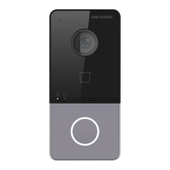
Video Intercom Villa Door Station
User Manual
Related Manuals for HIKVISION DS-KV6113-PE1
Summary of Contents for HIKVISION DS-KV6113-PE1
-
Page 1
Video Intercom Villa Door Station User Manual… -
Page 2
INTERRUPTION, OR LOSS OF DATA, CORRUPTION OF SYSTEMS, OR LOSS OF DOCUMENTATION, WHETHER BASED ON BREACH OF CONTRACT, TORT (INCLUDING NEGLIGENCE), PRODUCT LIABILITY, OR OTHERWISE, IN CONNECTION WITH THE USE OF THE PRODUCT, EVEN IF HIKVISION HAS BEEN ADVISED OF THE POSSIBILITY OF SUCH DAMAGES OR LOSS. -
Page 3
Video Intercom Villa Door Station User Manual PRODUCTION OF CHEMICAL OR BIOLOGICAL WEAPONS, ANY ACTIVITIES IN THE CONTEXT RELATED TO ANY NUCLEAR EXPLOSIVE OR UNSAFE NUCLEAR FUEL-CYCLE, OR IN SUPPORT OF HUMAN RIGHTS ABUSES. IN THE EVENT OF ANY CONFLICTS BETWEEN THIS MANUAL AND THE APPLICABLE LAW, THE LATER PREVAILS. -
Page 4
Video Intercom Villa Door Station User Manual Symbol Conventions The symbols that may be found in this document are defined as follows. Symbol Description Indicates a hazardous situation which, if not avoided, will or could Danger result in death or serious injury. Indicates a potentially hazardous situation which, if not avoided, could result in equipment damage, data loss, performance Caution… -
Page 5
Video Intercom Villa Door Station User Manual Safety Instruction ● WarningThe working temperature of the device is from -10 ºC to 55 ºC. ● All the electronic operation should be strictly compliance with the electrical safety regulations, fire prevention regulations and other related regulations in your local region. ●… -
Page 6
Video Intercom Villa Door Station User Manual by the battery manufacturer. ● Input voltage should meet both the SELV and the Limited Power Source according to 60950-1 standard. ● The power supply must conform to LPS. The recommended adaptor models and manufacturers are shown as below. -
Page 7
Video Intercom Villa Door Station User Manual Regulatory Information FCC Information Please take attention that changes or modification not expressly approved by the party responsible for compliance could void the user’s authority to operate the equipment. FCC compliance: This equipment has been tested and found to comply with the limits for a Class B digital device, pursuant to part 15 of the FCC Rules. -
Page 8
Video Intercom Villa Door Station User Manual designated collection point. For more information see:www.recyclethis.info Industry Canada ICES-003 Compliance This device meets the CAN ICES-3 (B)/NMB-3(B) standards requirements. -
Page 9: Table Of Contents
Video Intercom Villa Door Station User Manual Contents Chapter 1 Appearance ……………………. 1 Chapter 2 Terminal and Wiring Description ………………3 2.1 Terminal Description ………………….3 2.2 Wiring Description ……………………. 4 2.2.1 Door Lock Wiring ………………….4 2.2.2 Door Contact Wiring ………………..5 2.2.3 Exit Button Wiring ………………….
-
Page 10
Video Intercom Villa Door Station User Manual 5.5.8 Intercom Settings ………………… 32 5.5.9 Access Control Settings ……………….. 34 Chapter 6 Configuration via Client Software………………37 6.1 Device Management ………………….37 6.1.1 Add Online Device ………………..37 6.1.2 Add Device by IP Address………………38 6.1.3 Add Device by IP Segment ……………… -
Page 11: Chapter 1 Appearance
Video Intercom Villa Door Station User Manual Chapter 1 Appearance Front Panel and Rear Panel Here takes DS-KV6113-WPE1 for example. Figure 1-1 Front Panel and Rear Panel Table 1-1 Description Description Microphone Camera Indicator Unlock (Green)/ Call (Orange)/ Communicate (White) Button Card Reading Area Loudspeaker…
-
Page 12
Video Intercom Villa Door Station User Manual Description Debugging Port TAMPER Set Screw Bottom Panel Figure 1-2 Bottom Panel Table 1-2 Description Description TF Card Slot (Reserved) Network Interface… -
Page 13: Chapter 2 Terminal And Wiring Description
Video Intercom Villa Door Station User Manual Chapter 2 Terminal and Wiring Description 2.1 Terminal Description Figure 2-1 Terminal Description…
-
Page 14: Wiring Description
Video Intercom Villa Door Station User Manual 2.2 Wiring Description 2.2.1 Door Lock Wiring Figure 2-2 Door Lock Wiring Note Terminal NC/COM is set as default for accessing magnetic lock/electric bolt; terminal NO/COM is set as default for accessing electric strike.
-
Page 15: Door Contact Wiring
Video Intercom Villa Door Station User Manual 2.2.2 Door Contact Wiring Figure 2-3 Door Contact Wiring 2.2.3 Exit Button Wiring Figure 2-4 Exit Botton Wiring…
-
Page 16: Alarm Input Device Wiring
Video Intercom Villa Door Station User Manual 2.2.4 Alarm Input Device Wiring Figure 2-5 Alarm Input Device Wiring…
-
Page 17: Chapter 3 Installation
Video Intercom Villa Door Station User Manual Chapter 3 Installation Note ● Make sure the device in the package is in good condition and all the assembly parts are included. ● Make sure your power supply matches your door station. ●…
-
Page 18: Surface Mounting Without Protective Shield
Video Intercom Villa Door Station User Manual 3.2 Surface Mounting without Protective Shield Before You Start ● Tools that you need to prepare for installation: Drill (ø2.846) and gradienter. ● Purchase the protective shield before installation. Steps 1. Stick the mounting template on the wall. Drill screw holes according to the mounting template. Remove the template from the wall.
-
Page 19: Surface Mounting With Protective Shield
Video Intercom Villa Door Station User Manual Figure 3-3 Surface Mounting without Protective Shield 3.3 Surface Mounting with Protective Shield Before You Start ● Tools that you need to prepare for installation: Drill (ø2.846) and gradienter. ● Purchase the protective shield before installation. Steps 1.
-
Page 20
Video Intercom Villa Door Station User Manual Figure 3-4 Mounting Template 2. Align the protective shield with the mounting template. 3. Secure the mounting plate and protective shield on the wall with 4 supplied screws according to the screw holes. 4. -
Page 21
Video Intercom Villa Door Station User Manual Figure 3-5 Flush Mounting with Protective Shield… -
Page 22: Chapter 4 Activation
Video Intercom Villa Door Station User Manual Chapter 4 Activation 4.1 Activate Device via Web You are required to activate the device first by setting a strong password for it before you can use the device. Default parameters of the door station are as follows: ●…
-
Page 23: Edit Network Parameters
Video Intercom Villa Door Station User Manual Note We highly recommend you to create a strong password of your own choosing (using a minimum of 8 characters, including at least three kinds of following categories: upper case letters, lower case letters, numbers, and special characters) in order to increase the security of your product. And we recommend you change your password regularly, especially in the high security system, changing the password monthly or weekly can better protect your product.
-
Page 24: Chapter 5 Remote Configuration Via Web
Video Intercom Villa Door Station User Manual Chapter 5 Remote Configuration via Web 5.1 Live View In the browser address bar, enter the IP address of the device, and press the Enter key to enter the login page. Enter the user name and password and click Login to enter the Live View page. Or you can click Live View to enter the page.
-
Page 25: Number Settings
Video Intercom Villa Door Station User Manual 5.3 Number Settings Link the room No. and SIP numbers. Click Number Settings to enter the page. Click Add, set the Room No. and SIP numbers in the pop-up dialog box. 5.4 Device Management You can manage the linked device on the page.
-
Page 26: System Settings
Video Intercom Villa Door Station User Manual Play Performance Set the live view performance to Shortest Delay, Balanced or Fluent. Auto Start Live View Check Yes to enable the function. Image Format Select the image format for picture capture. Click Save to enable the settings. Record File Parameters Record File Size Select the packed size of the manually recorded and downloaded video files to 256M, 512M or…
-
Page 27
Video Intercom Villa Door Station User Manual ● Enable Manual Time Sync., set the time manually or check the Sync. with computer time. Click Save to enable the settings. Click System Settings → DST to check Enable DST. Set the parameters according to your needs and click Save to enable the settings. -
Page 28: Network Settings
Video Intercom Villa Door Station User Manual Authentication Click Security → Authentication to enter the settings page. On the page, you can select RTSP Authenticationaccording to your actual needs. Click Save to enable the settings. Security Service Click Security → Security Service to enter the settings page. On the page, you can enable SSH according to your actual needs.
-
Page 29
Video Intercom Villa Door Station User Manual device supports IPv4. Steps 1. Click Network → Basic Settings → TCP/IP to enter the settings page. Figure 5-4 TCP/IP Settings 2. Configure the network parameters. – Check DHCP, the device will get the parameters automatically. –… -
Page 30
Video Intercom Villa Door Station User Manual Figure 5-5 Port Settings 2. Set the ports of the device. HTTP Port The default port number is 80, and it can be changed to any port No. which is not occupied. HTTPS Port The default port number is 443, and it can be changed to any port No. -
Page 31
Video Intercom Villa Door Station User Manual SIP Setting Steps 1. Click Network → Basic Settings → SIP to enter the settings page. Figure 5-6 SIP Settings 2. Check Enable VOIP Gateway. 3. Configure the SIP parameters. 4. Click Save to enable the settings. FTP Settings Steps 1. -
Page 32
Video Intercom Villa Door Station User Manual Figure 5-7 FTP Settings 2. Check Enable FTP. 3. Select Server Type. 4. Input the Server IP Address and Port. 5. Configure the FTP Settings, and the user name and password are required for the server login. 6. -
Page 33: Video & Audio Settings
Video Intercom Villa Door Station User Manual Platform Access Platform access provides you an option to manage the devices via platform. Steps 1. Click Network → Advanced Settings → Platform Access to enter the settings page. 2. Check the checkbox of Enable to enable the function. 3.
-
Page 34
Video Intercom Villa Door Station User Manual Figure 5-8 Video Parameters 2. Select the Stream Type. 3. Configure the video parameters. Stream Type Select the stream type to main stream or sub stream. Video Type Select the stream type to video stream, or video & audio composite stream. The audio signal will be recorded only when the Video Type is Video &… -
Page 35
Video Intercom Villa Door Station User Manual Video Encoding The device supports H.264. I Frame Interval Set I Frame Interval from 1 to 400. 4. Click Save to save the settings. Audio Parameters Steps 1. Click Video/Audio → Audio to enter the settings page. Figure 5-9 Audio Settings 2. -
Page 36: Image Settings
Video Intercom Villa Door Station User Manual 5.5.5 Image Settings Display Settings Configure the image adjustment, backlight settings and other parameters in display settings. Steps 1. Click Image → Display Settings to enter the display settings page. Figure 5-10 Display Settings 2.
-
Page 37
Video Intercom Villa Door Station User Manual Figure 5-11 Day/Night Mode Set Day Mode or Night Mode manually.Set the mode as Auto and edit the sensitivity according to your needs.Set the mode as Scheduled-Switch. Set the start time and end time. Note Daytime is from configured start time to configured time. -
Page 38
Video Intercom Villa Door Station User Manual Figure 5-12 Backlight 1) Check the checkbox to enable BLC. 2) Select BLC Area. 6. Click Save to enable the settings. OSD Settings You can customize the camera name, time/date format, display mode, and OSD size displayed on the live view. -
Page 39: Event Settings
Video Intercom Villa Door Station User Manual 5. Select Cropping Resolution. 6. Click Save. 5.5.6 Event Settings Motion Detection Motion detection detects the moving objects in the configured security area, and a series of actions can be taken when the alarm is triggered. Steps 1.
-
Page 40
Video Intercom Villa Door Station User Manual 3. Click Draw Area. Click and drag the mouse on the live video to draw a motion detection area. Click Stop Drawing to finish drawing one area. Click Save to save the settings. Clear Area Click Clear All to clear all of the areas. -
Page 41: Schedule Settings
Video Intercom Villa Door Station User Manual Figure 5-14 Event Linkage 2. Select the Major Type as Device Event or Door Event. 3. Select the type of the Normal Linkage for the event. 4. Click Save to enable the settings. 5.5.7 Schedule Settings You can create call schedule, or else the device will call indoor station all day by default.
-
Page 42: Intercom Settings
Video Intercom Villa Door Station User Manual 2. Click the next row below Enable Indoor Station All Day by Default. 3. Enter Schedule Name. 4. Select Call Type. 5. Set Weekly Schedule. 1) Click Weekly Schedule. 2) Drag mouse to set the schedule according to the actual needs. 3) Optional: Click the copy icon to copy the schedule to other days according to the actual needs.
-
Page 43
Video Intercom Villa Door Station User Manual Figure 5-15 Device ID Settings 2. Select the device type from the drop-down list, and set the corresponding information. 3. Click Save to enable the device number configuration. Note ● For main door station (D series or V series), the serial No. is 0. ●… -
Page 44: Access Control Settings
Video Intercom Villa Door Station User Manual Ring-Back Tone Settings Click Intercom → Ringbacktone Settings to enter the settings page. Click Add to select the ring tone from PC. Note Available Audio Format: WAV、AAC, Size: Less than 600 KB, Sample Rate: 8000Hz, Mono. Press Button to Call Steps 1.
-
Page 45
Video Intercom Villa Door Station User Manual Figure 5-17 Door Parameters 2. Select the door and edit the door name. 3. Set door contact status. 4. Set lock action time. 5. Click Save to enable the settings. Card Security Go to Access Control → Card Security to enter the settings page. Slide to enable card encryption parameters and CPU card reading content. -
Page 46
Video Intercom Villa Door Station User Manual Figure 5-18 Elevator Control 2. Check to enable elevator control function. 3. Select an Elevator No., and select an elevator controller type for the elevator. 4. Set the Negative Floor. 5. Select the Interface Type as RS-485 or Network Interface. And enable the elevator control. –… -
Page 47: Chapter 6 Configuration Via Client Software
Video Intercom Villa Door Station User Manual Chapter 6 Configuration via Client Software 6.1 Device Management Device management includes device activation, adding device, editing device, and deleting device, and so on. After running the iVMS-4200, video intercom devices should be added to the client software for remote configuration and management.
-
Page 48: Add Device By Ip Address
Video Intercom Villa Door Station User Manual Figure 6-1 Add to the Client 6.1.2 Add Device by IP Address Steps 1. Click +Add to pop up the adding devices dialog box. 2. Select IP/Domain as Adding Mode. 3. Enter corresponding information. 4.
-
Page 49: Add Device By Ip Segment
Video Intercom Villa Door Station User Manual 6.1.3 Add Device by IP Segment You can add many devices at once whose IP addresses are among the IP segment. Steps 1. Click +Add to pop up the dialog box. 2. Select IP Segment as Adding Mode. 3.
-
Page 50: Person Management
Video Intercom Villa Door Station User Manual Note ● The lower-level organizations will be deleted as well if you delete an organization. ● Make sure there is no person added under the organization, or the organization cannot be deleted. 6.4 Person Management After adding the organization, you can add person to the organization and manage the added person such as issuing cards in batch, importing and exporting person’s information in batch, etc.
-
Page 51: Modify And Delete Person
Video Intercom Villa Door Station User Manual Click Remote Take the person’s photo with the collection device. Collection 3. Issue the card for the person. 1) Click Credential → Card. 2) Click + to pop up the Add Card dialog. 3) Select Normal Card as Card Type.
-
Page 52: Import And Export Person Information
Video Intercom Villa Door Station User Manual 6.4.4 Import and Export Person Information The person information can be imported and exported in batch. Steps 1. Exporting Person: You can export the added persons’ information in Excel format to the local 1) After adding the person, you can click Export Person to pop up the following dialog.
-
Page 53: Issue Card In Batch
Video Intercom Villa Door Station User Manual 6.4.6 Issue Card in Batch You can issue multiple cards for the person with no card issued in batch. Steps 1. Click Batch Issue Cards to enter the dialog page. All the added person with no card issued will display in the Person(s) with No Card Issued list.
-
Page 54: Permission Settings
Video Intercom Villa Door Station User Manual Figure 6-3 Card Settings 3. Select Card Type and Card No. Type. 4. Click OK to save the settings. Result After issuing the card to the person, the person and card information will display in the Person(s) with Card Issued list.
-
Page 55: Video Intercom Settings
Video Intercom Villa Door Station User Manual 4. Click Save. 5. Check the permission and click Apply All to Device. The status of the permission displays as Applied. 6. Optional: Click Applying Status to check the details. Modify/Delete Permissions On the page of the permission settings, click to edit the parameters of the permission.
-
Page 56: Release Notice
Video Intercom Villa Door Station User Manual Note ● One video intercom device can only connect with one client software. ● The maximum ring duration can be set from 15s to 60s via the Remote Configuration of the video intercom device. ●…
-
Page 57
Video Intercom Villa Door Station User Manual Figure 6-4 Search Call Logs 2. Set the search conditions, including call status, device type, start time and end time. Call Status Click ˅ to unfold the drop-down list and select the call status as Dialed, Received or Missed. Or select All to search logs with all statuses. -
Page 58: Upload Armed Information
Video Intercom Villa Door Station User Manual Select Advertising Information, Property Information, Alarm Information or Notice Information as Type according to your needs. Start Time/End Time Click the time icon to specify the start time and end time of a time period to search the logs. Reset the Settings Click Reset to reset all the configured search conditiions.
-
Page 59: Communication Matrix And Device Command
Device Command Scan the following QR code to get the device common serial port commands. Note that the command list contains all commonly used serial ports commands for all Hikvision access control and video intercom devices. Figure A-2 Device Command…
-
Page 60
UD20205B…
Посмотреть инструкция для Hikvision DS-KV6113-PE1 бесплатно. Руководство относится к категории домофон-системы, 1 человек(а) дали ему среднюю оценку 9.4. Руководство доступно на следующих языках: английский. У вас есть вопрос о Hikvision DS-KV6113-PE1 или вам нужна помощь? Задайте свой вопрос здесь
Не можете найти ответ на свой вопрос в руководстве? Вы можете найти ответ на свой вопрос ниже, в разделе часто задаваемых вопросов о Hikvision DS-KV6113-PE1.
Какой размер экрана Hikvision DS-KV6113-PE1?
Размер экрана Hikvision DS-KV6113-PE1 составляет — «.
Какая высота Hikvision DS-KV6113-PE1?
Hikvision DS-KV6113-PE1 имеет высоту 27 mm.
Какая ширина Hikvision DS-KV6113-PE1?
Hikvision DS-KV6113-PE1 имеет ширину 138 mm.
Какая толщина Hikvision DS-KV6113-PE1?
Hikvision DS-KV6113-PE1 имеет толщину 65 mm.
Инструкция Hikvision DS-KV6113-PE1 доступно в русский?
К сожалению, у нас нет руководства для Hikvision DS-KV6113-PE1, доступного в русский. Это руководство доступно в английский.
Не нашли свой вопрос? Задайте свой вопрос здесь
Video Intercom Villa Door Station User Manual
Legal Information
© 2020 Hangzhou Hikvision Digital Technology Co., Ltd. All rights reserved.
About this Manual
The Manual includes instructions for using and managing the Product. Pictures, charts, images and
all other information hereinafter are for description and explanation only. The information
contained in the Manual is subject to change, without notice, due to firmware updates or other
reasons. Please find the latest version of this Manual at the Hikvision website
(https://www.hikvision.com/).
Please use this Manual with the guidance and assistance of professionals trained in supporting the
Product.
Trademarks
and other Hikvision’s trademarks and logos are the properties of
Hikvision in various jurisdictions.
Other trademarks and logos mentioned are the properties of their respective owners.
Disclaimer
TO THE MAXIMUM EXTENT PERMITTED BY APPLICABLE LAW, THIS MANUAL AND THE PRODUCT
DESCRIBED, WITH ITS HARDWARE, SOFTWARE AND FIRMWARE, ARE PROVIDED «AS IS» AND
«WITH ALL FAULTS AND ERRORS». HIKVISION MAKES NO WARRANTIES, EXPRESS OR IMPLIED,
INCLUDING WITHOUT LIMITATION, MERCHANTABILITY, SATISFACTORY QUALITY, OR FITNESS FOR
A PARTICULAR PURPOSE. THE USE OF THE PRODUCT BY YOU IS AT YOUR OWN RISK. IN NO EVENT
WILL HIKVISION BE LIABLE TO YOU FOR ANY SPECIAL, CONSEQUENTIAL, INCIDENTAL, OR INDIRECT
DAMAGES, INCLUDING, AMONG OTHERS, DAMAGES FOR LOSS OF BUSINESS PROFITS, BUSINESS
INTERRUPTION, OR LOSS OF DATA, CORRUPTION OF SYSTEMS, OR LOSS OF DOCUMENTATION,
WHETHER BASED ON BREACH OF CONTRACT, TORT (INCLUDING NEGLIGENCE), PRODUCT
LIABILITY, OR OTHERWISE, IN CONNECTION WITH THE USE OF THE PRODUCT, EVEN IF HIKVISION
HAS BEEN ADVISED OF THE POSSIBILITY OF SUCH DAMAGES OR LOSS.
YOU ACKNOWLEDGE THAT THE NATURE OF INTERNET PROVIDES FOR INHERENT SECURITY RISKS,
AND HIKVISION SHALL NOT TAKE ANY RESPONSIBILITIES FOR ABNORMAL OPERATION, PRIVACY
LEAKAGE OR OTHER DAMAGES RESULTING FROM CYBER-ATTACK, HACKER ATTACK, VIRUS
INSPECTION, OR OTHER INTERNET SECURITY RISKS; HOWEVER, HIKVISION WILL PROVIDE TIMELY
TECHNICAL SUPPORT IF REQUIRED.
YOU AGREE TO USE THIS PRODUCT IN COMPLIANCE WITH ALL APPLICABLE LAWS, AND YOU ARE
SOLELY RESPONSIBLE FOR ENSURING THAT YOUR USE CONFORMS TO THE APPLICABLE LAW.
ESPECIALLY, YOU ARE RESPONSIBLE, FOR USING THIS PRODUCT IN A MANNER THAT DOES NOT
INFRINGE ON THE RIGHTS OF THIRD PARTIES, INCLUDING WITHOUT LIMITATION, RIGHTS OF
PUBLICITY, INTELLECTUAL PROPERTY RIGHTS, OR DATA PROTECTION AND OTHER PRIVACY RIGHTS.
YOU SHALL NOT USE THIS PRODUCT FOR ANY PROHIBITED END-USES, INCLUDING THE
DEVELOPMENT OR PRODUCTION OF WEAPONS OF MASS DESTRUCTION, THE DEVELOPMENT OR
i
На чтение 9 мин Просмотров 19 Опубликовано 11 апреля 2023 Обновлено 11 апреля 2023
Содержание
- Подключение комплекта домофона Hikvision DS-KV6113-WPE1 и DS-KH6320-WTE1
- Подключение и настройка ip домофона Hikvision
- Содержание:
- 1. Подключение ip домофона Hikvision
- 2. Настройка ip домофона Hikvision
- 3. Настройка монитора ip домофона Hikvision в программе IVMS — 4200
- 4. Выпуск карт ip домофона Hikvision
- 5. Подключение электро замка к ip домофону Hikvision
- 6. Подключение ip камеры
- 7. Добавление подчинённого монитора к основному монитору ip домофона
- 8. Настройка многоабонентской системы ip домофонии Hikvision
- Быстрая настройка IP-домофона и вызывной панели Hikvision
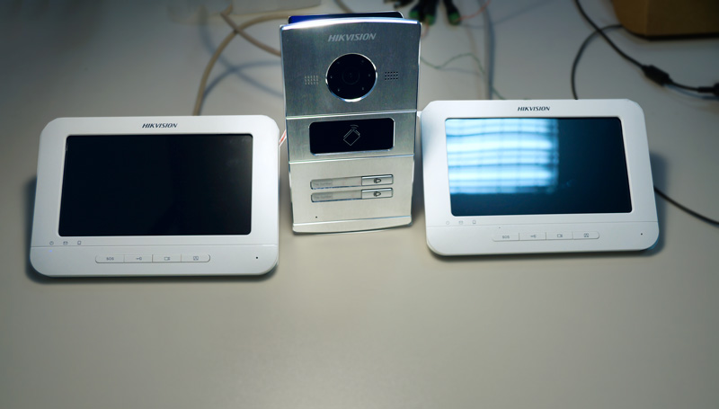
Подключение комплекта домофона Hikvision DS-KV6113-WPE1 и DS-KH6320-WTE1

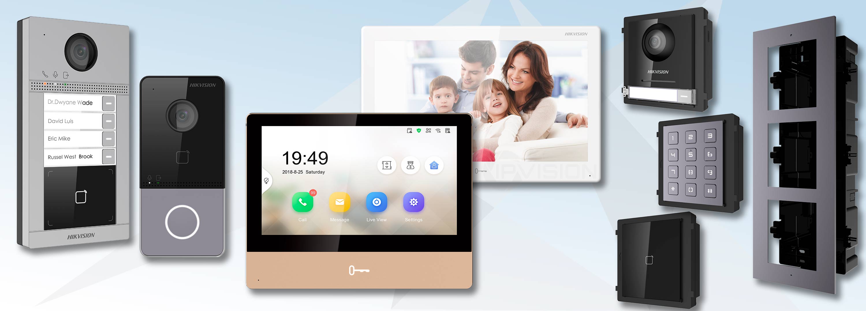
В этой статье мы будем подключать комплект домофонии Hikvision который включает в себя:
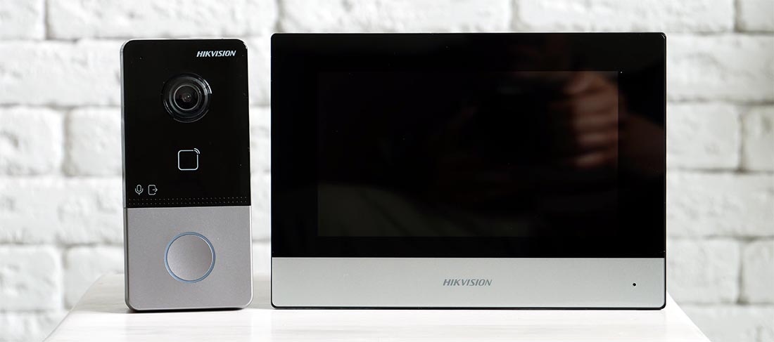
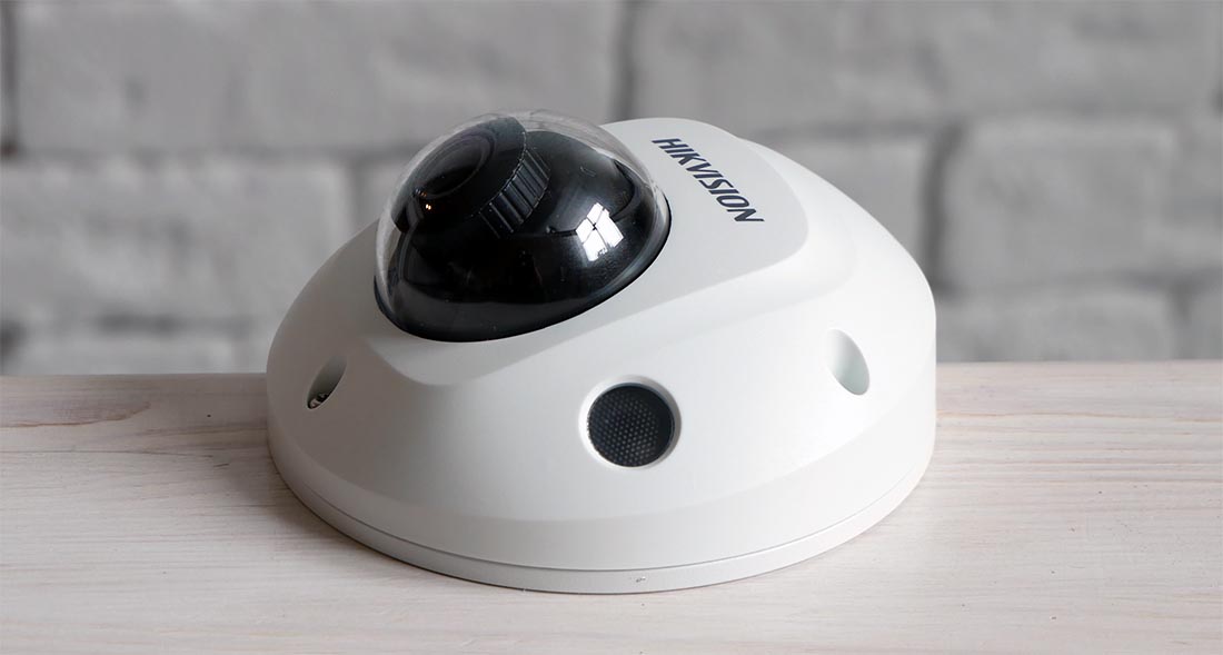
Камера видеонаблюдения Hikvision DS-2CD2523G0-IS
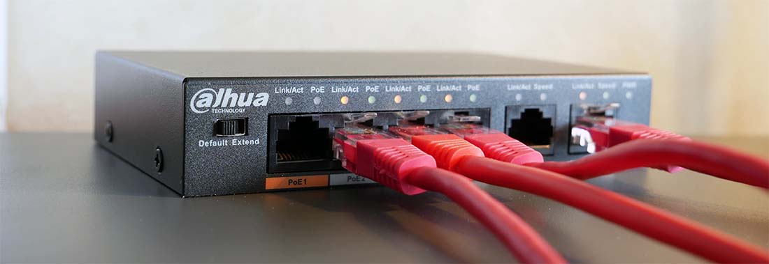
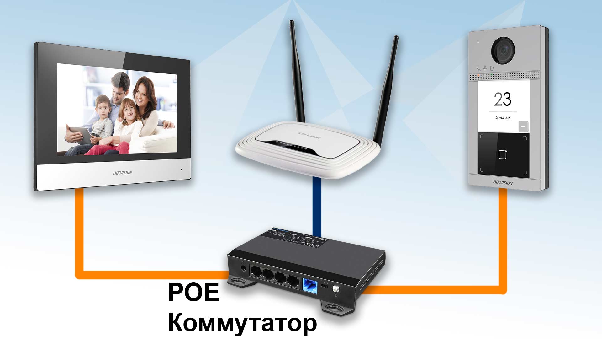
Для подключения и настройки нам понадобиться PoE коммутатор (например Dahua DH-PFS3006-4ET-60), утилита Hikvision SADP Tool и пару патч-кордов.
Подключаем домофон панель и камеру к РоЕ коммутатору, а сам РоЕ коммутатор к интернет роутеру.
Устанавливаем и запускаем утилиту Hikvision SADP Tool и видим 3 наших устройства со статусом Inactive.
Этот статус говорит нам что устройства подключаются впервые или сброшены на заводские настройки.
Нам нужно активировать каждое устройство по инструкции —
После активации статусы на устройствах поменяются на Active.
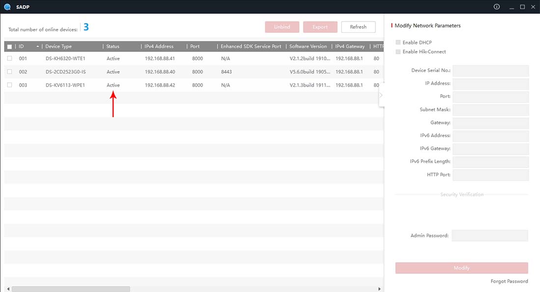
Вся последующая настройка выполняться с экрана домофона в 4 шага.
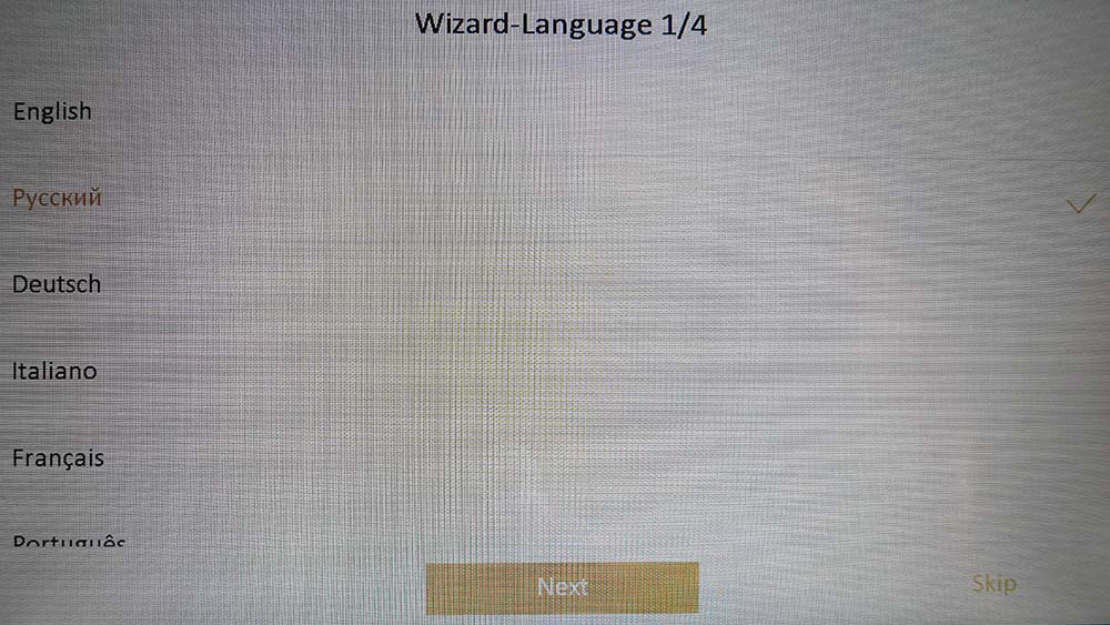
Шаг 1 — Выбираем язык Русский — нажимаем Nex
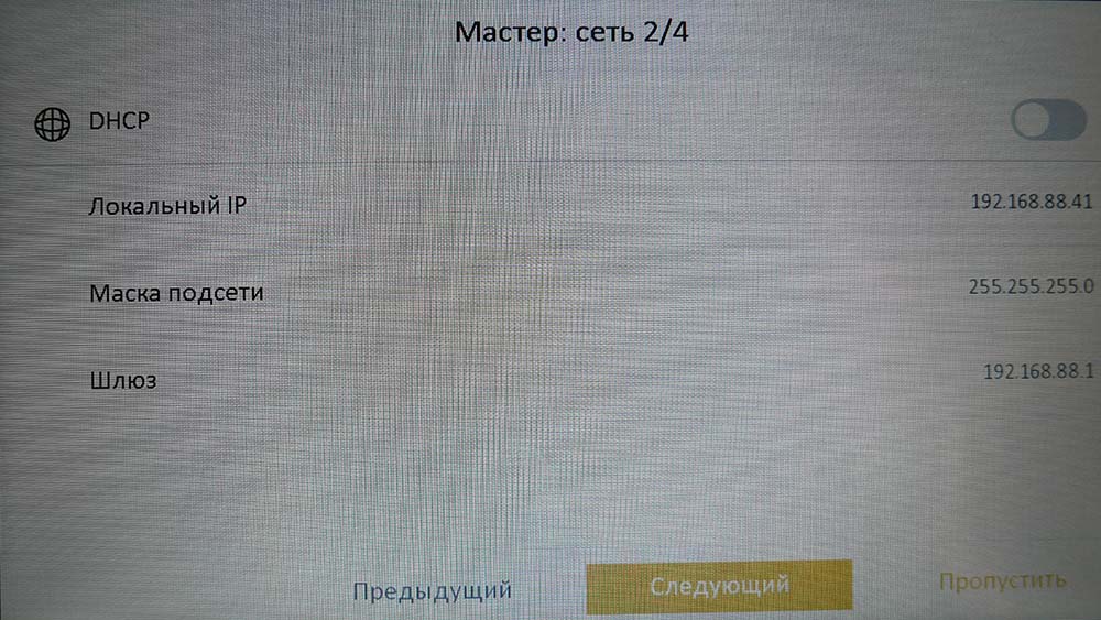
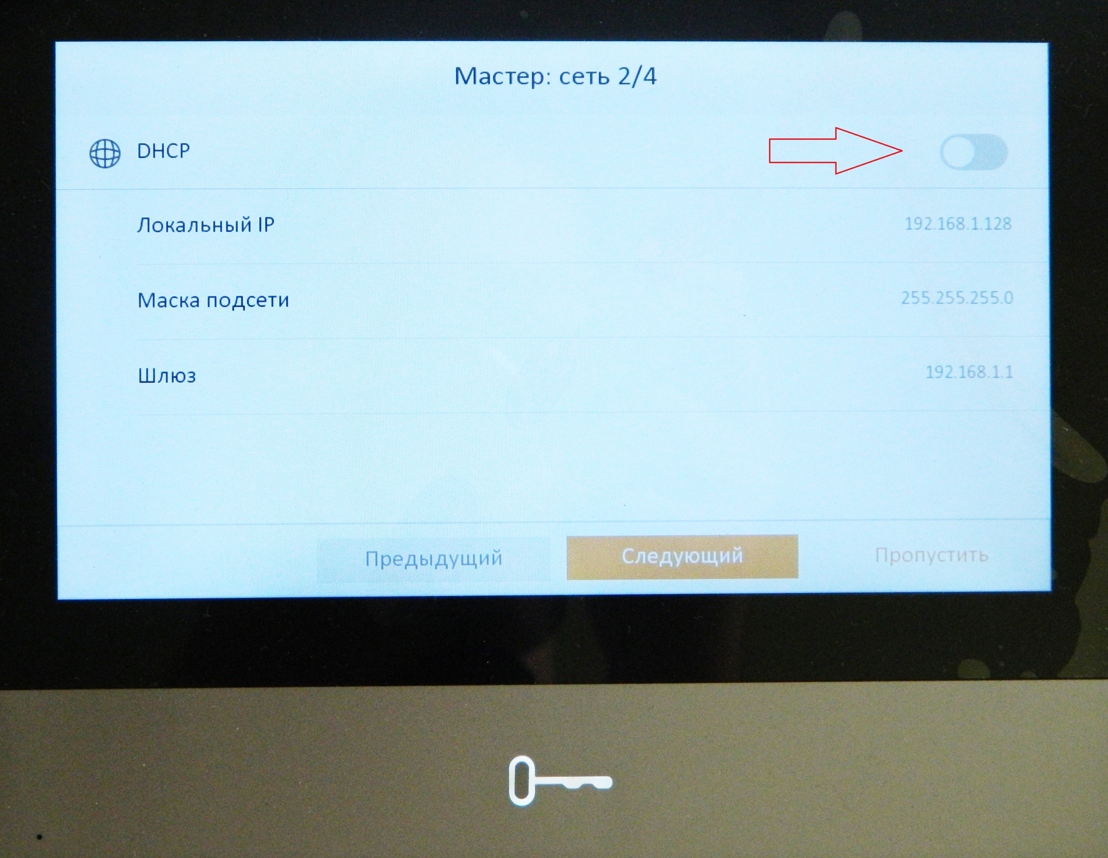
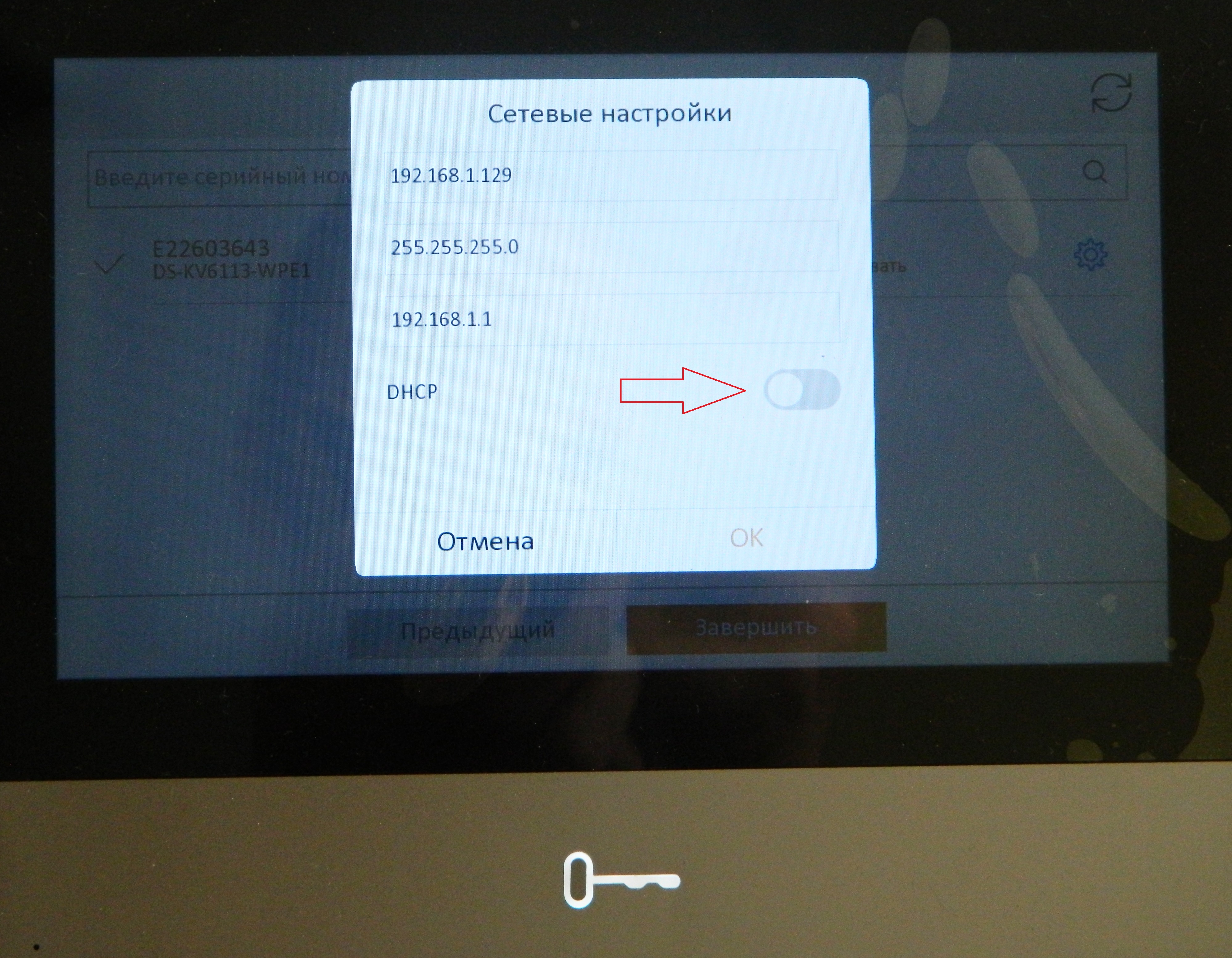
Шаг 2 — Активируем галочку DHCP (через 1-2 сек она вернётся обратно — это нормально) — нажимаем Следующий
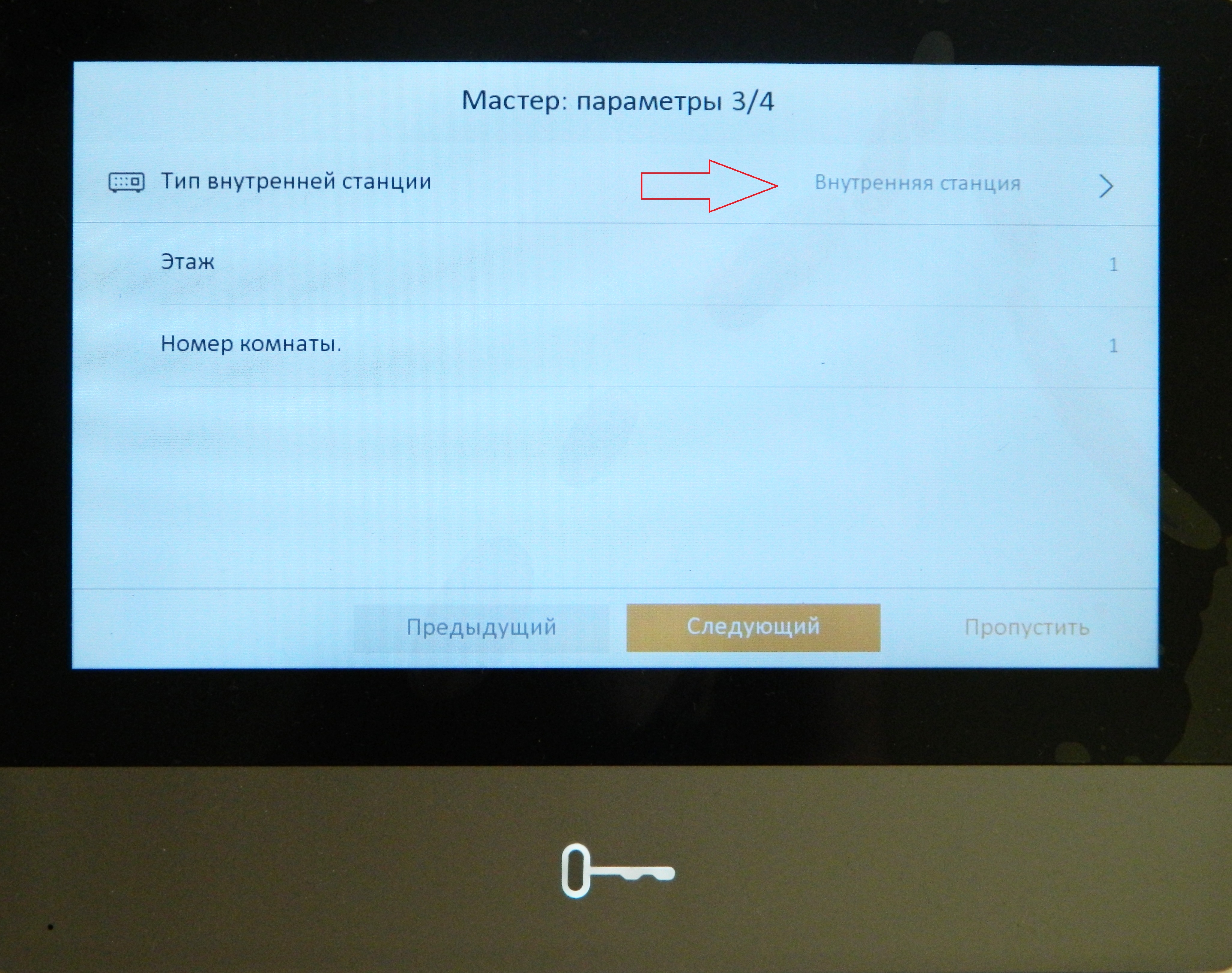
Шаг 3 — Если у Вас один домофон нажимаем — Следующий

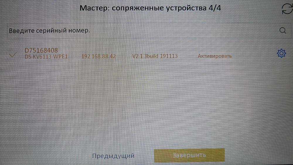
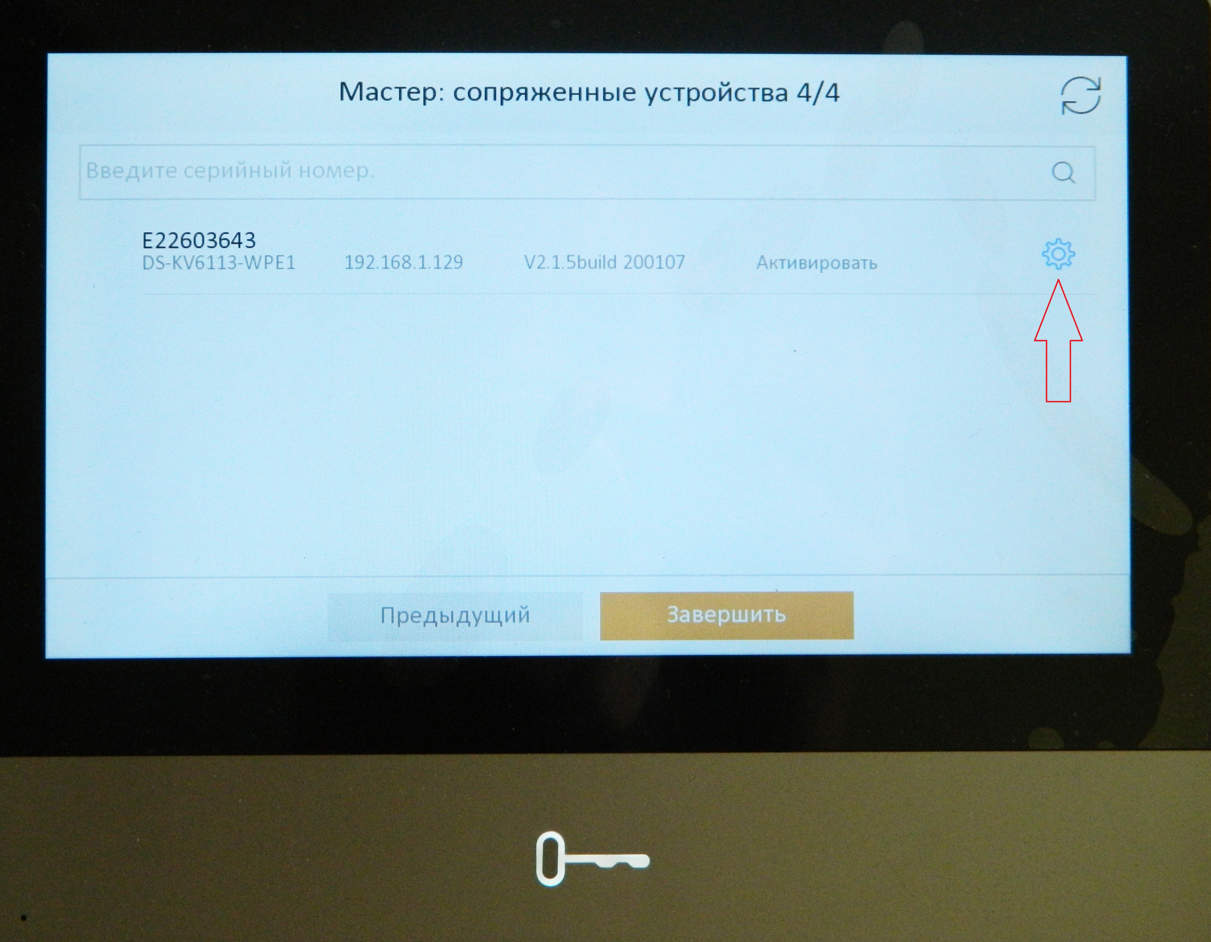
Шаг 4 — Отмечаем найденную панель и нажимаем Завершить.
На этом подключение вызывной панели к домофону закончено.
Настройка вызова на смартфон.
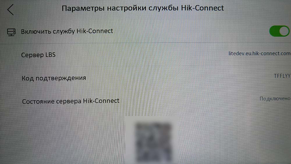
Для начала нужно включить службу Hik-Connect.
Заходим — Настройки — Больше — Параметры настройки службы Hik-Connect, включаем службу и проверяем статус — Подключено.
После этого заходим в приложение Hik-Connect на смартфоне, нажимаем Добавить устройство
Сканируем QR код который расположен внизу экрана меню настроек службы Hik-Connect домофона (или наклеен на самом домофоне)
Далее — Добавить
Вводим код подтверждения указанный в меню настроек службы Hik-Connect домофона, нажимаем — Ок.
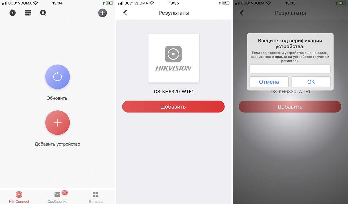
Через мобильное приложение можно пообщаться с посетителем и открыть дверь.
Надеемся данная статья была полезной. Если у Вас возникнут вопросы, пишите в чат или звоните в нашу техническую поддержку.
Источник
Подключение и настройка ip домофона Hikvision
Здесь подробная фото и видео инструкция о порядке подключения и настройки ip домофонов Hikvision. Подробнее о функционале ip домофонии читайте в статье Возможности ip видеодомофона Hikvision
Содержание:
Подключение ip домофона Hikvision
Настройка ip видеодомофона Hikvision
Выпуск карт ip домофона Hikvision
Подключение электро-механического замка к ip домофону Hikvision
Подключение ip камеры к ip домофону Hikvision
Добавление второго (подчинённого) монитора к основному монитору ip видеодомофона
Настройка многоабонентской системы ip домофонии Hikvision
Установка ip домофона Hikvision
Подключение ip домофона Hikvision к интернету
Подключение тревожных датчиков к ip домофону Hikvision
1. Подключение ip домофона Hikvision
IP домофоны Hikvision поддерживают питание 12В и подключение по технологии PoE (Питание и данные подаются на устройство по одному сетевому кабелю Витая пара)
Рассмотрим вариант подключения системы ip домофонии по технологии РОЕ, т.к. такой способ наиболее удобный и практичный. Монитор ip домофона Hikvision и ip вызывную панель подключаем к РОЕ Коммутатору в свободный РОЕ порт. После объединяем порт Up-Link коммутатора с вашим интернет — роутером в вашу локальную компьютеную сеть. Если всё же ваш электрик сделал разводку витой пары по старой аналоговой схеме, соединив кабелем напрямую два сетевых устройства, не отчаевайтесь, сделать ip домофонию есть возможность и при такой разводке.
2. Настройка ip домофона Hikvision
В программе SADP активируем вызывную панель и монитор домофонной системы. После активации присваиваем каждому устройству ip адрес и шлюз (Gateway)
У ip вызывных панелей Hikvision есть свой web интерфейс, можете зайти на него через браузер Internet explorer и произвести настройку. Но у мониторов ip домофона Hikvision нет своего web интерфейса, поэтому настройку устройств можно производить локально в меню на экране сенсорного монитора или на компьютере в программе IVMS-4200.
Добавляем наши ip домофоны в клиент IVMS — 4200 логин и пароль — тот что задали при активации
Если в вашей системе ip домофонии будет более 2х устройств, например многоабонентская система, то для корректной работы советую всё же прошить каждое устройство последней прошивкой. Здесь найдете ссылки на последнюю прошивку для ip домофонов Hikvision (ссылки на версии прошивок ). После прошивки устройств Hikvision, что бы избежать остаточных багов, обязательно сбросте устройство до заводских настроек, кстати это правило касается не только ip домофонии.
Видео подключение и настройки ip домофона Hikvision
3. Настройка монитора ip домофона Hikvision в программе IVMS — 4200
Для настройки монитора ip домофона Hikvision в бесплатной программе IVMS — 4200 нужно добавить устройство в эту программу. Здесь же можно и произвести первичную активацию устройства, если вы не активировали вашу вызывную и монитор ранее в удобной и простой утилите SADP.
1. При выборе online device в нижнем поле отобразяться все ваши устройства в сети. Выбираем монитор и жмем добавить «Add».

2. В открывшемся диалоговом окне указываем любое имя устройству, ставим галочку синхронизировать время, указываем логин и пароль, тот который вы задали при активации.
3. Нажимаем шестеренку и попадаем в меню настроек. Основная логика заключается в том, что бы на мониторе ip домофона в меню настроек конфигурация связанной сети указать ip адрес вашей вызывной панели в строку Main Door Station ip adress.
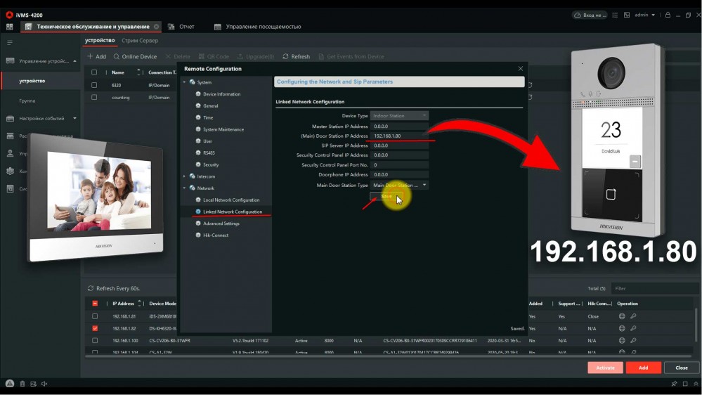
4. Всё, ip домофония связана и готова к работе, проверьте, нажав на кнопку вызова, должен пойти вызов на моиторе домофона.
4. Выпуск карт ip домофона Hikvision
ip домофоны Hikvision поддерживают стандарт карт Mifare.
Для выпуска карт необходимо сначала прислонить к считывателю мастер карту (в комплекте поставки). Затем программируем нужное количество карт для абонентов просто поочередно прикладывая карты к считывателю, завершаем выпуск карт повторно прислонив мастер карту к считывателю. Так же можно начать выпуск карт из меню web интерфейса самой вызывной панели. Такой способ удобен, если вы потеряли мастер карту от вызывной панели.
5. Подключение электро замка к ip домофону Hikvision
Для подключения к ip домофону Hikvision электро-механического замка необходимо плюс питания соединить с электро -механическим замком и синим кабелем вызывной панели, а минус соединить с зеленым кабелем вызывной панели .
6. Подключение ip камеры
Для подключения к ip домофону Hikvision цифровой камеры необходимо в мониторе видеодомофона зайти в настройки, далее -конфигурация, пароль администратора (пароль которй вы задали при активации монитора) . Затем — Устройство — добавить устройство — выбрать тип устройства — ip камера, затем в открывшемся окне присвойте любое имя для камеры, введите ip адрес камеры видеонаблюдения, а так же логин и пароль от камеры, жмем сохранить. Важно! Вторичный поток в ip камере должен быть выставлен кодеком H.264
7. Добавление подчинённого монитора к основному монитору ip домофона
Для подключения второго, подчиненного монитора к основному монитору ip домофона Hikvision, нужно зайти в настройки добавочного монитора видеодомофона, далее — интерком, конфигурация идентификатора — тип устройства: Добавочный номер станции, ниже в строке указываем номер 1 — сохранить — перезагрузка устройства. После перезагрузки монитор стал добавочным. 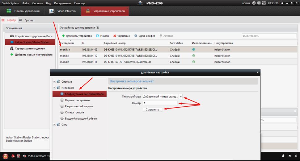
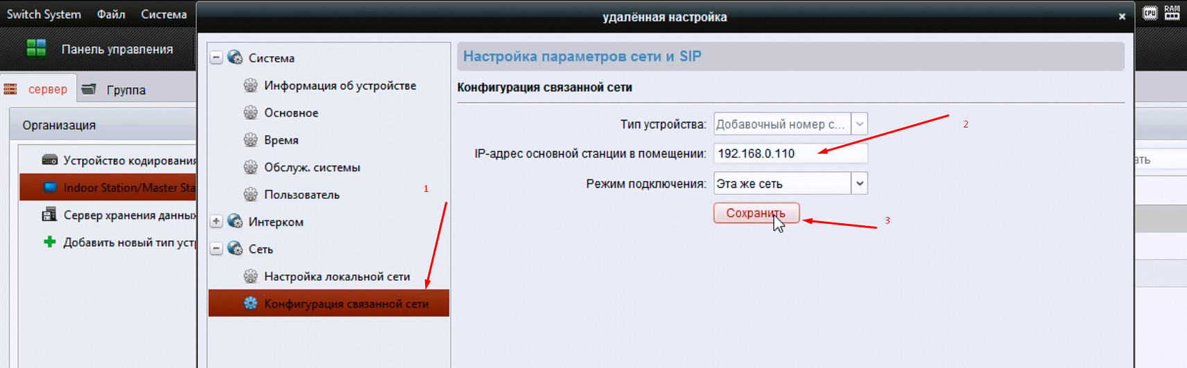
Затем повторно заходим на дополнительный монитор и в разделе сеть выбираем конфигурация связанной сети в строке ip адрес основной станции в помещении прописываем ip адрес главного монитора (не вызывной панели), в нашем случае это 192.168.0.110 , жмем сохранить.
8. Настройка многоабонентской системы ip домофонии Hikvision
Логика настройки многоабонентской ip домофонии Hikvision
Для всех мониторов:
1. указать №№ квартир (101, 102, 103 и т.д.)
2. указать ip адрес (главного) домофона (нашей многоабонетской ip вызывной панели)
Для главной многоабонетской ip вызывной панели:
1. Присвоить каждой кнопке № квартиры (101, 102, 103 и т.д.). Всё, настройка выполнена
Если же в системе есть подчиненные/межкомнатные вызывные панели ip домофонов hikvision, то
1. их необходимо перевести в режим не главной вызывной панели (Sub Villa Door Station), а после указать подчиненным панелям кто главная вызывная вызывная (прописать ip адрес Main Villa Door Station)
2. указать № квартиры (монитора — 101 или 102 или 103 и т.д.)
Ниже на видео пошагово как это сделать
Источник
Быстрая настройка IP-домофона и вызывной панели Hikvision
Сегодня всё популярнее становится установка IP домофонии в частных домах, в виду своей возможности наблюдать за происходящим с помощью камеры с вызывной панели, прохода по карточкам RFID и не сложной самостоятельной первоначальной настройке.
Выбранные в данном проекте устройства (видеодомофн Hikvision IP DS-KH8350-WTE1 7 и вызывная панель DS-KV61X3-(W)PE1) обладают технологией PoE, что позволяет питать устройства по витой паре, подключим вызывную панель и домофон к PoE-свитчу. Также подключим электромеханический замок по схеме:
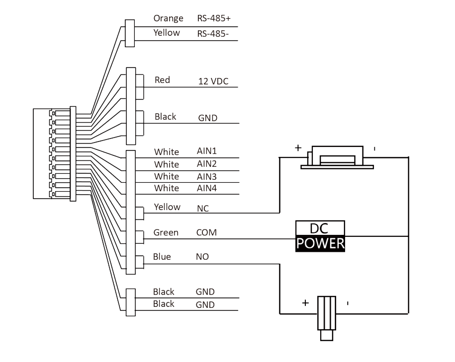
Где NO – выход реле дверного замка (нормально разомкнутый), а COM – общий интерфейс
При первом включении домофона появится мастер первоначальной настройки, на первом экране нужно задать пароль пользователя:
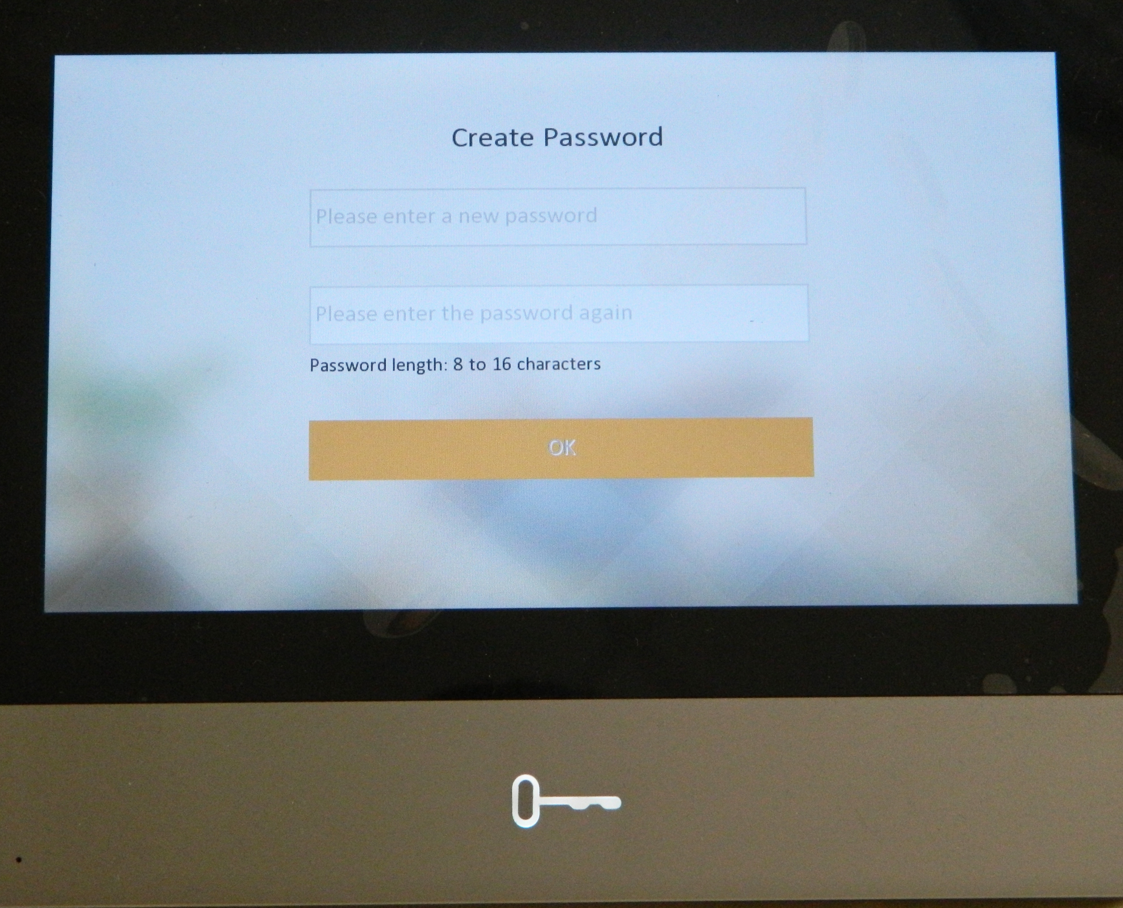
Первоначальная настройка состоит из четырёх этапов, первый – выбор языка интерфейса:
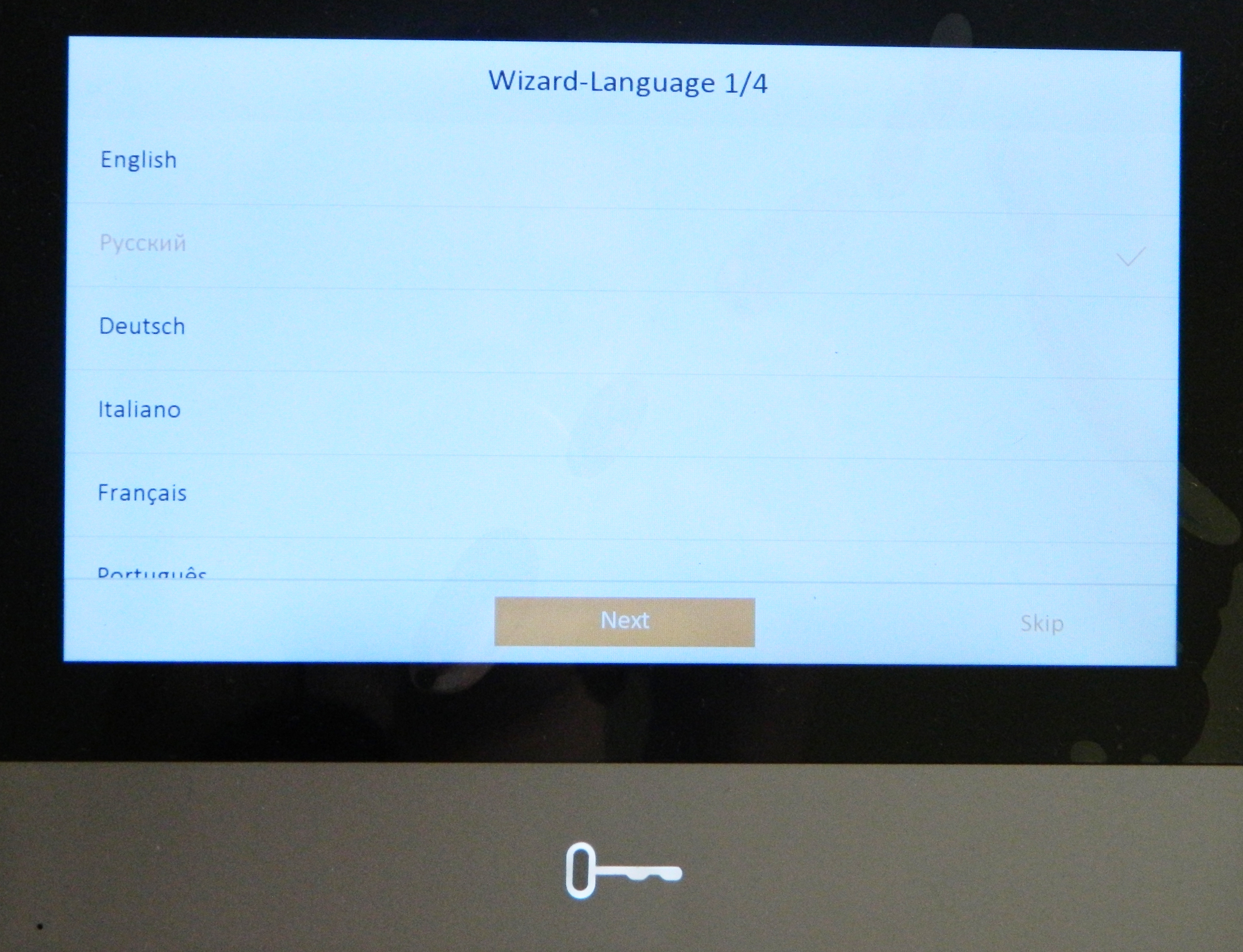
Вторым этапом является настройка сети, в верхней части экрана есть кнопка “DHCP”, предназначенная для автоматического получения настроек от роутера:
Третий этап отвечает за выбор типа внутренней станции, оставляем параметр «Внутренняя станция»:
На последнем, четвёртом этапе, остаётся добавить вызывную панель, которая автоматически отобразится в списке, если подключена к той же сети, что и домофон, для конфигурации нажмём шестерёнку в правом столбце, напротив наименования:
Здесь, также, есть кнопка “DHCP” для получения автоматических настроек сети:
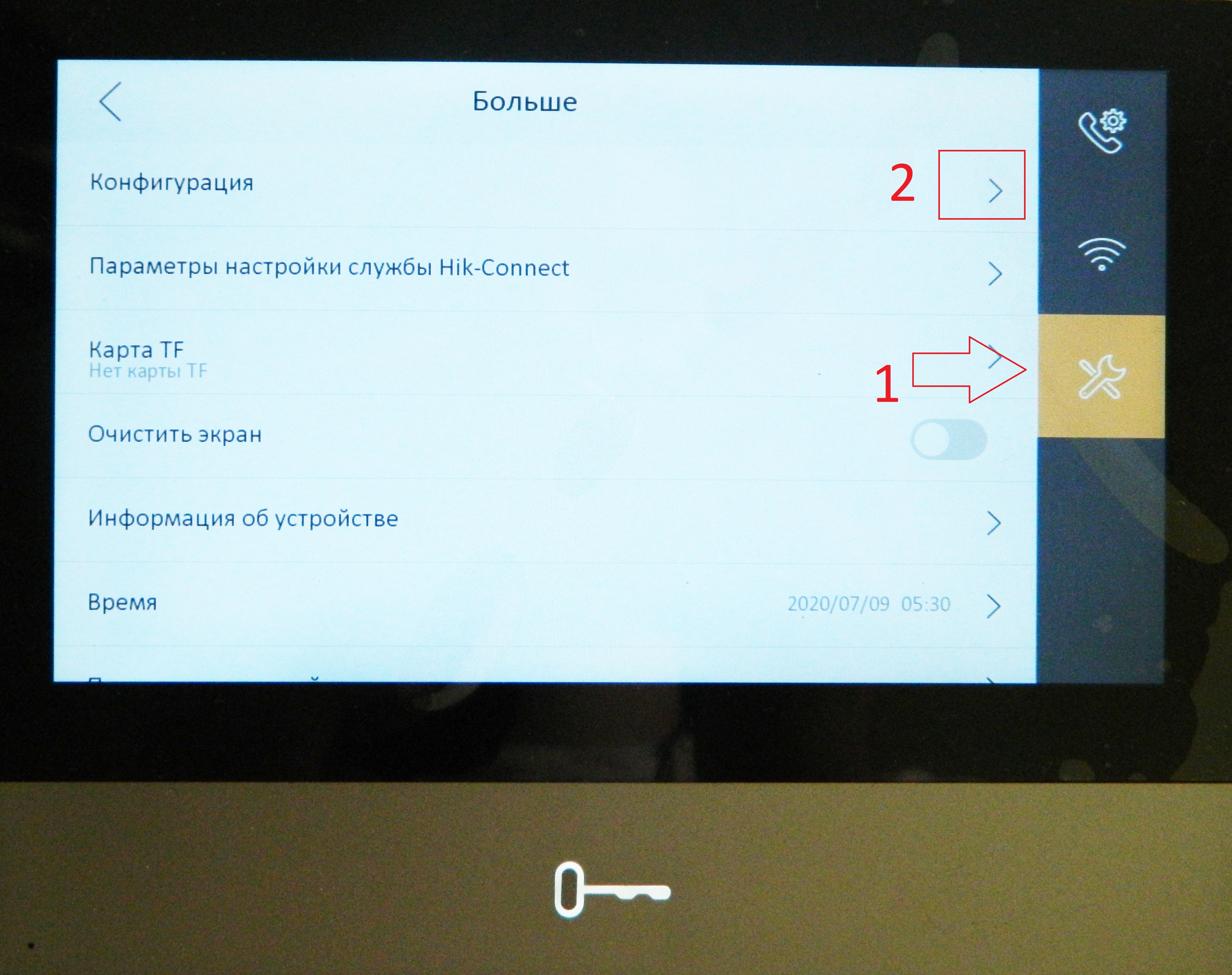
После мастера настроек вы попадёте на главный экран, откуда мы сразу переходим в настройки:
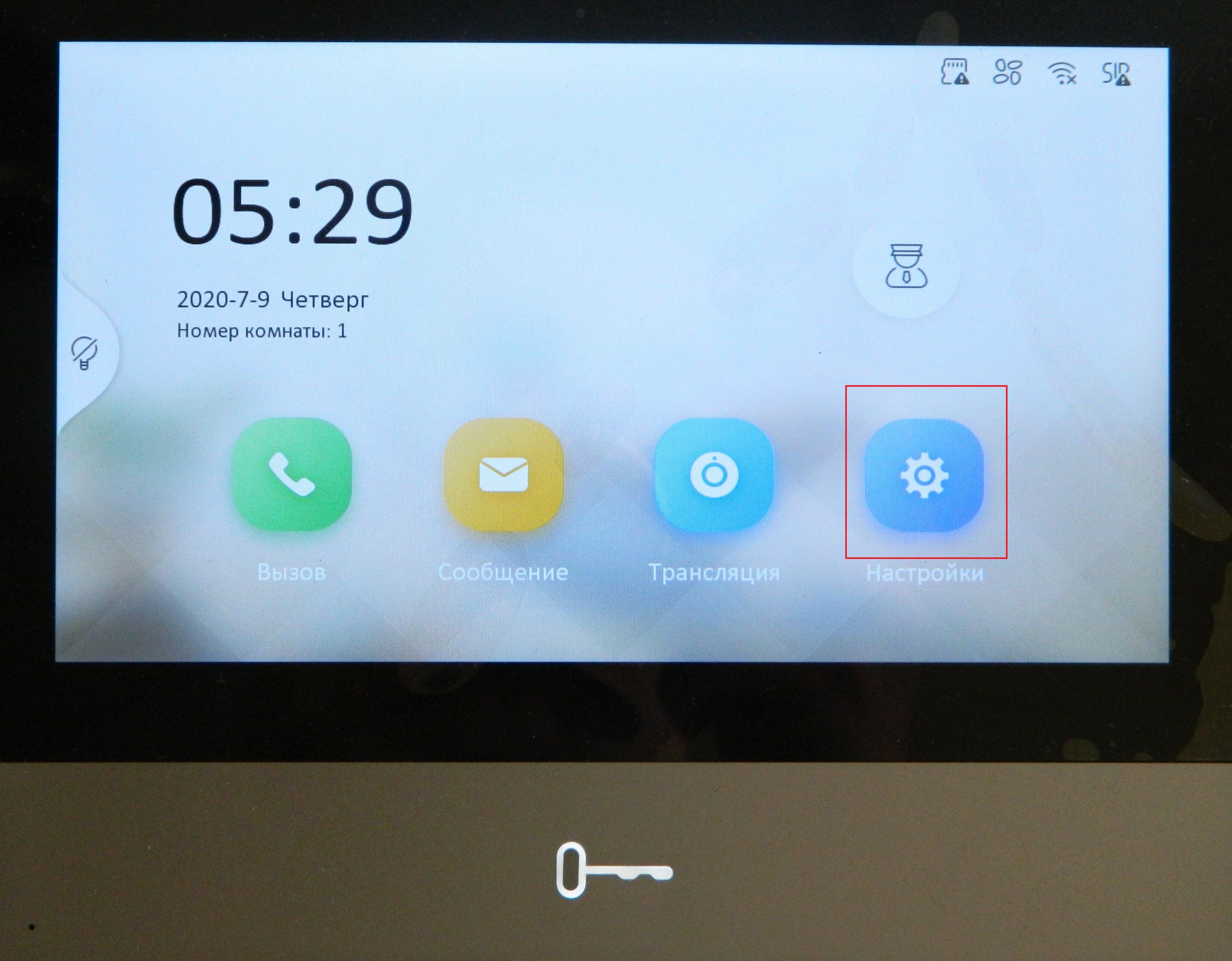
В правом столбце переходим в третий пункт и выбираем «Конфигурация» (пароль администратора – 888999):
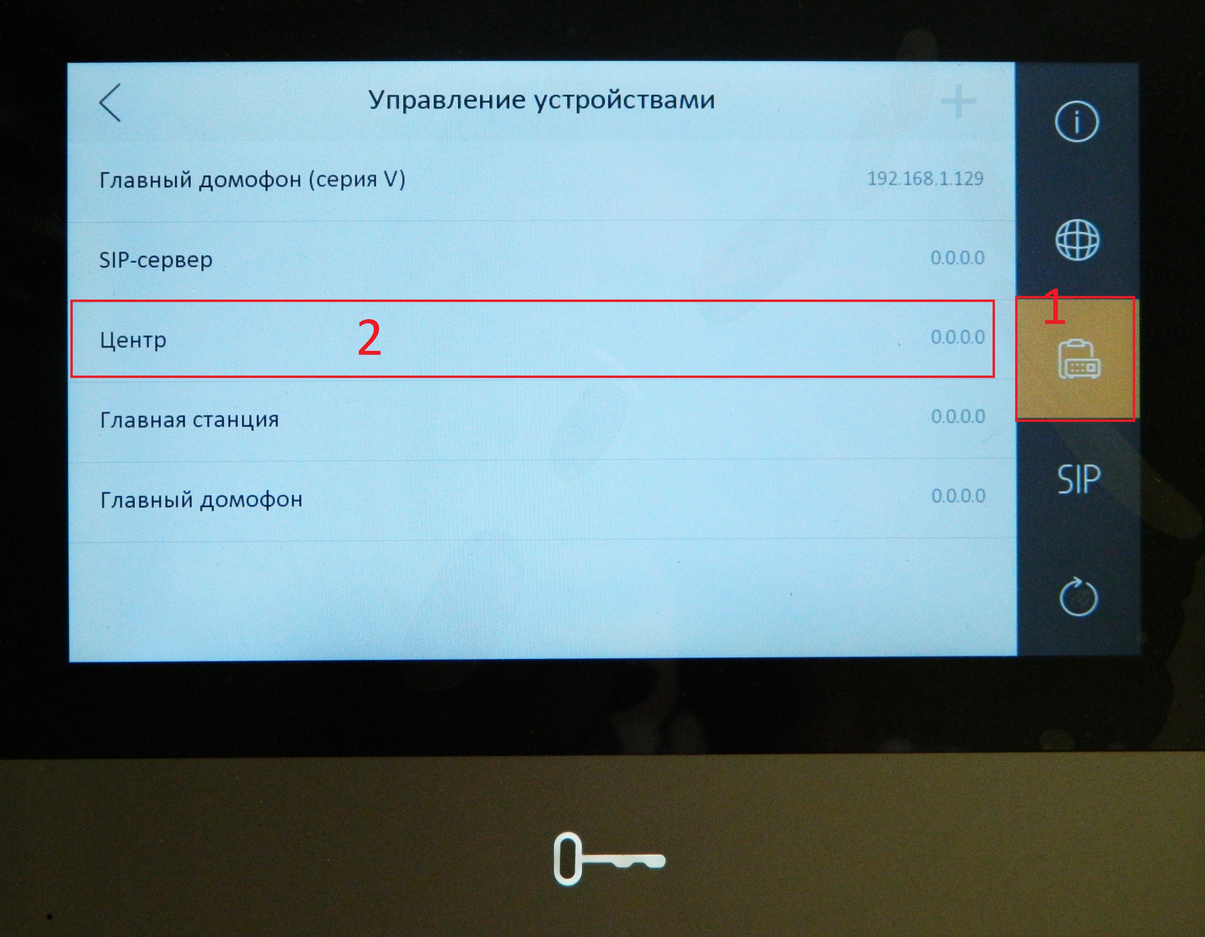
Далее переходим в 3 пункт меню «Управление устройствами» и прописываем в настройке «Центр» IP-адрес домофона:
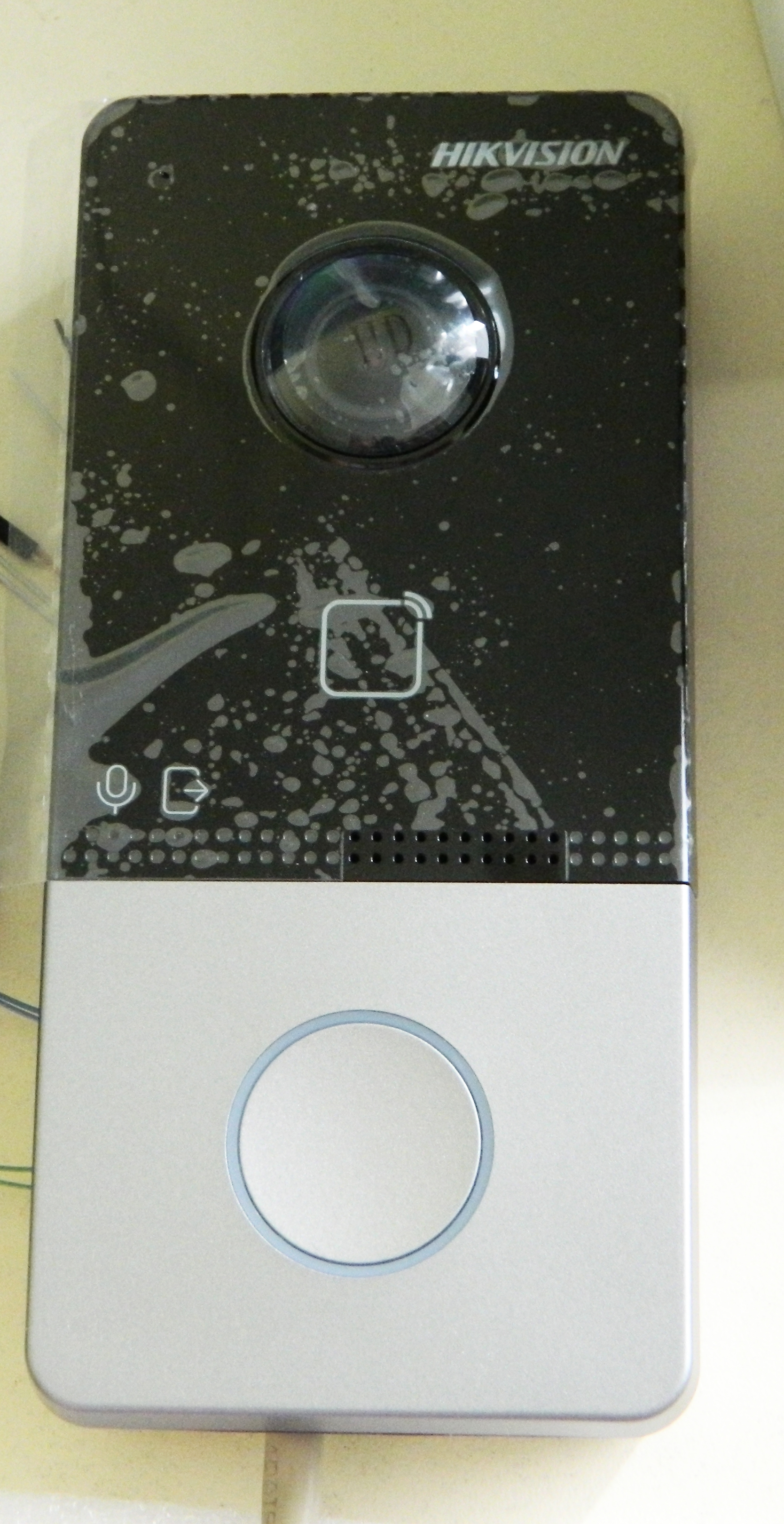
Для теста нажмём на вызывной панели кнопку вызова, расположенную снизу:
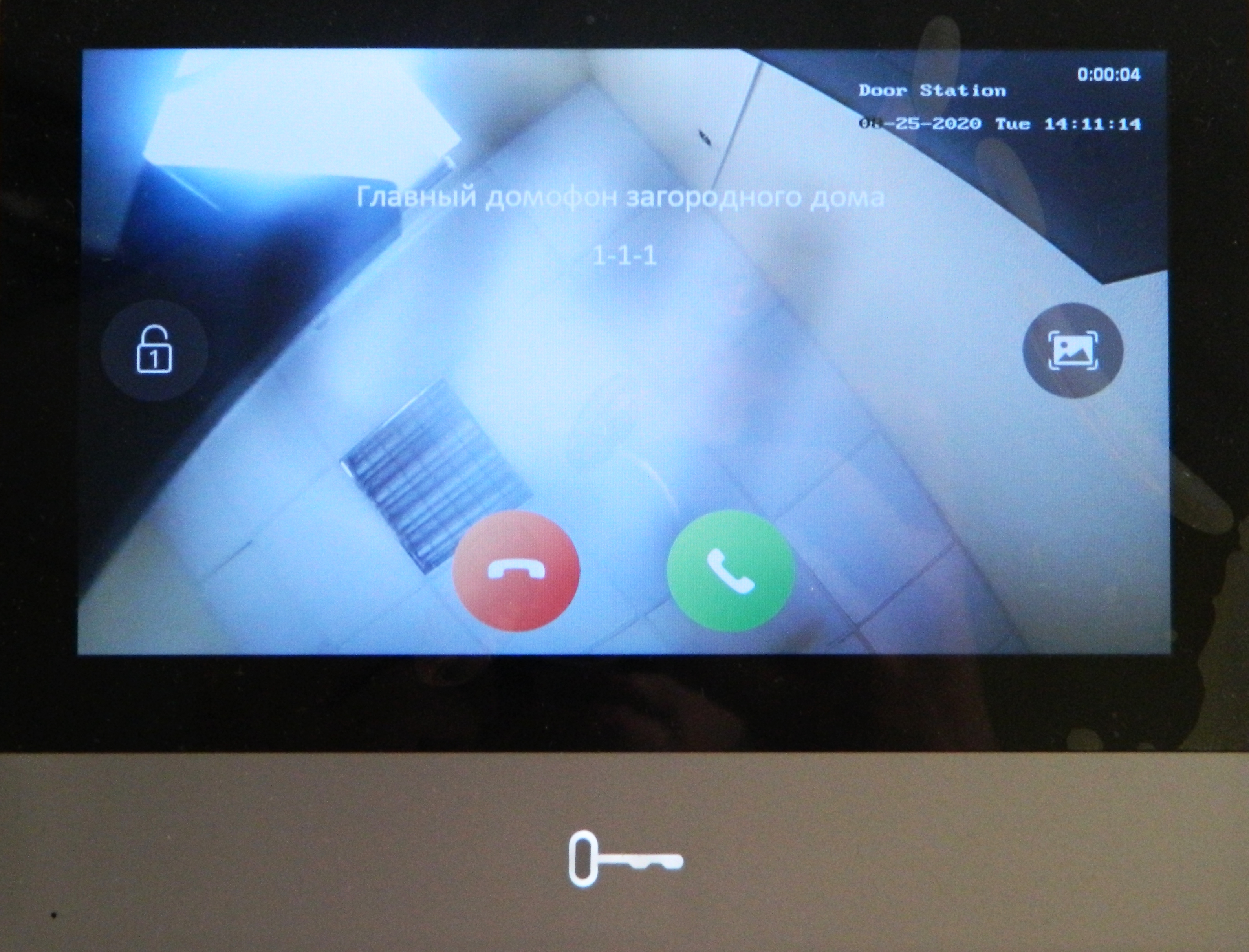
Если всё настроено верно, то на домофон должен прийти вызов с отображением происходящего с камеры панели, при вызове Вы можете принять или отклонить вызов, также в левой части экрана находится кнопка разблокирования двери, в правой части кнопка для создания скриншота:
Для добавления карточек нужно приложить к считывателю сначала карточку «мастер-ключ» из комплекта со считывателем или вызывной панелью, после чего приложить программируемый ключ (формат Mifare)
Источник
Описание
Дополнительное оборудование
(289290) DS-KABV6113-RS, Кронштейн
(230602) Малогабаритный источник питания 12В, Моллюск 12/1,5
Характеристики
|
Напряжение питания (от монитора), В 12; PoE |
Угол обзора, град 131° (г)/78° (в) |
|
Линия связи с абонентским устройством IP |
|
|
Габаритные размеры, мм 138х65х27 |
|
|
Разрешение видео 2 Мп (1920х1080) |
Диапазон рабочих температур, °С -40…+55 |
Напряжение питания (от монитора), В
12; PoE
Разрешение видео
2 Мп (1920х1080)
Угол обзора, град
131° (г)/78° (в)
Линия связи с абонентским устройством
IP
Габаритные размеры, мм
138х65х27
Диапазон рабочих температур, °С
-40…+55