-
Contents
-
Table of Contents
-
Bookmarks
Quick Links
Video Intercom Villa Door Station
User Manual
Related Manuals for HIKVISION DS-KV6113 Series
Summary of Contents for HIKVISION DS-KV6113 Series
-
Page 1
Video Intercom Villa Door Station User Manual… -
Page 2
WITHOUT LIMITATION, MERCHANTABILITY, SATISFACTORY QUALITY, OR FITNESS FOR A PARTICULAR PURPOSE. THE USE OF THE PRODUCT BY YOU IS AT YOUR OWN RISK. IN NO EVENT WILL HIKVISION BE LIABLE TO YOU FOR ANY SPECIAL, CONSEQUENTIAL, INCIDENTAL, OR INDIRECT DAMAGES,… -
Page 3
LOSS OF DOCUMENTATION, WHETHER BASED ON BREACH OF CONTRACT, TORT (INCLUDING NEGLIGENCE), PRODUCT LIABILITY, OR OTHERWISE, IN CONNECTION WITH THE USE OF THE PRODUCT, EVEN IF HIKVISION HAS BEEN ADVISED OF THE POSSIBILITY OF SUCH DAMAGES OR LOSS. YOU ACKNOWLEDGE THAT THE NATURE OF INTERNET PROVIDES FOR… -
Page 4
Video Intercom Villa Door Station User Manual Symbol Conventions The symbols that may be found in this document are defined as follows. Symbol Description Indicates a hazardous situation which, if not avoided, will or Danger could result in death or serious injury. Indicates a potentially hazardous situation which, if not Caution avoided, could result in equipment damage, data loss,… -
Page 5
Video Intercom Villa Door Station User Manual Safety Instruction Warning • The working temperature of the device is from -10 ºC to 55 ºC. • All the electronic operation should be strictly compliance with the electrical safety regulations, fire prevention regulations and other related regulations in your local region. -
Page 6
Video Intercom Villa Door Station User Manual • Please use the provided glove when open up the device cover, avoid direct contact with the device cover, because the acidic sweat of the fingers may erode the surface coating of the device cover. •… -
Page 7
Video Intercom Villa Door Station User Manual Regulatory Information FCC Information Please take attention that changes or modification not expressly approved by the party responsible for compliance could void the user’s authority to operate the equipment. FCC compliance: This equipment has been tested and found to comply with the limits for a Class B digital device, pursuant to part 15 of the FCC Rules. -
Page 8
Video Intercom Villa Door Station User Manual EU Conformity Statement This product and — if applicable — the supplied accessories too are marked with «CE» and comply therefore with the applicable harmonized European standards listed under the EMC Directive 2014/30/EU, the RoHS Directive 2011/65/EU 2012/19/EU (WEEE directive): Products marked with this symbol cannot be disposed of as unsorted municipal waste in the European Union. -
Page 9: Table Of Contents
Video Intercom Villa Door Station User Manual Contents 1 Appearance ………………..1 2 Terminal and Wiring Description …………..3 2.1 Terminal Description ………………3 2.2 Wiring Description ……………….. 3 2.2.1 Door Lock Wiring ………………3 2.2.2 Door Contact Wiring …………….. 4 2.2.3 Exit Button Wiring ………………
-
Page 10
Video Intercom Villa Door Station User Manual 5.3.3 Network Settings ………………19 5.3.4 Video & Audio Settings …………….24 5.3.5 Image Settings ………………26 5.3.6 Event Settings ………………28 5.3.7 Intercom Settings ………………30 6 Configuration via Client Software …………. 35 6.1 Device Management ……………… -
Page 11
Video Intercom Villa Door Station User Manual 6.5.2 Search Call Logs ………………45 6.5.3 Upload Armed Information …………..46 A. Communication Matrix and Device Command ……..47… -
Page 12: Appearance
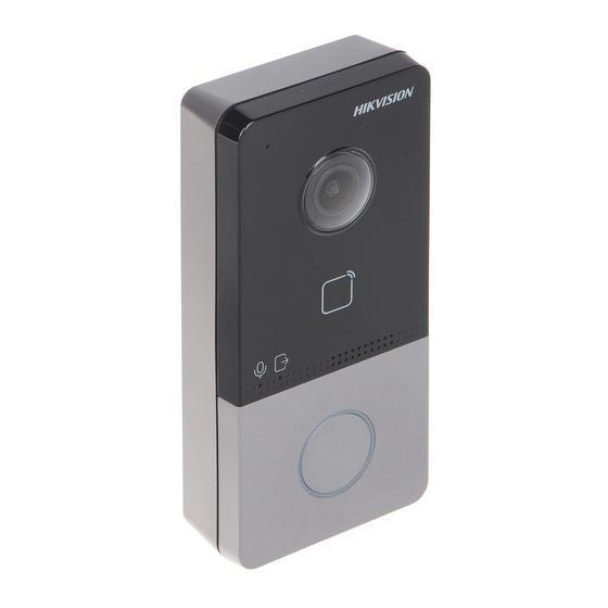
Video Intercom Villa Door Station User Manual 1 Appearance Front Panel and Rear Panel Here takes DS-KV6113-WPE1 for example. Figure 1-1 Front Panel and Rear Panel Table 1-1 Description Description Microphone Camera Indicator Unlock (Green)/ Call (Orange)/ Communicate (White) Button Card Reading Area…
-
Page 13
Video Intercom Villa Door Station User Manual Description Loudspeaker Terminals Debugging Port TAMPER Set Screw Bottom Panel Figure 1-2 Bottom Panel Table 1-2 Description Description TF Card Slot Network Interface… -
Page 14: Terminal And Wiring Description
Video Intercom Villa Door Station User Manual 2 Terminal and Wiring Description 2.1 Terminal Description Figure 2-1 Terminal Description 2.2 Wiring Description 2.2.1 Door Lock Wiring Figure 2-2 Door Lock Wiring…
-
Page 15: Door Contact Wiring
Video Intercom Villa Door Station User Manual Note Terminal NC/COM is set as default for accessing magnetic lock/electric bolt; terminal NO/COM is set as default for accessing electric strike. 2.2.2 Door Contact Wiring Figure 2-3 Door Contact Wiring 2.2.3 Exit Button Wiring Figure 2-4 Exit Botton Wiring…
-
Page 16: Alarm Input Device Wiring
Video Intercom Villa Door Station User Manual 2.2.4 Alarm Input Device Wiring Figure 2-5 Alarm Input Device Wiring…
-
Page 17: Installation
Video Intercom Villa Door Station User Manual 3 Installation Note • Make sure the device in the package is in good condition and all the assembly parts are included. • Make sure your power supply matches your door station. • Make sure all the related equipment is power-off during the installation.
-
Page 18: Surface Mounting Without Protective Shield
Video Intercom Villa Door Station User Manual 3.2 Surface Mounting without Protective Shield Before You Start • Tools that you need to prepare for installation: Drill (ø2.846) and gradienter. • Purchase the protective shield before installation. Steps 1. Stick the mounting template on the wall. Drill screw holes according to the mounting template.
-
Page 19: Surface Mounting With Protective Shield
Video Intercom Villa Door Station User Manual Figure 3-3 Surface Mounting without Protective Shield 3.3 Surface Mounting with Protective Shield Before You Start • Tools that you need to prepare for installation: Drill (ø2.846) and gradienter. • Purchase the protective shield before installation. Steps 1.
-
Page 20
Video Intercom Villa Door Station User Manual Figure 3-4 Mounting Template 2. Align the protective shield with the mounting template. 3. Secure the mounting plate and protective shield on the wall with 4 supplied screws according to the screw holes. 4. -
Page 21
Video Intercom Villa Door Station User Manual Figure 3-5 Flush Mounting with Protective Shield… -
Page 22: Activation
Video Intercom Villa Door Station User Manual 4 Activation 4.1 Activate Device via Web You are required to activate the device first by setting a strong password for it before you can use the device. Default parameters of the door station are as follows: •…
-
Page 23: Edit Network Parameters
Video Intercom Villa Door Station User Manual 3. Select an inactivated device and click Activate. 4. Create a password, and confirm the password. Note We highly recommend you to create a strong password of your own choosing (using a minimum of 8 characters, including at least three kinds of following categories: upper case letters, lower case letters, numbers, and special characters) in order to increase the security of your product.
-
Page 24: Remote Configuration Via Web
Video Intercom Villa Door Station User Manual 5 Remote Configuration via Web 5.1 Live View In the browser address bar, enter the IP address of the device, and press the Enter key to enter the login page. Enter the user name and password and click Login to enter the Live View page. Or you can click Live View to enter the page.
-
Page 25: Parameters Settings
Video Intercom Villa Door Station User Manual Figure 5-2 Organization Structure Settings 2. Click Fresh to refresh the list. 3. Enter the Keyword and click Search. The person information will display in the list. 5.3 Parameters Settings Click Configuration to set the parameters of the device. Note Run the browser, click →…
-
Page 26
Video Intercom Villa Door Station User Manual Set the stream type as Main Stream or Sub-stream. Play Performance Set the live view performance to Shortest Delay, Balanced or Fluent. Rules It refers to the rules on your local browser, select enable or disable to display or not display the colored marks when the motion detection, face detection, or intrusion detection is triggered. -
Page 27: System Settings
Video Intercom Villa Door Station User Manual Set the saving path of the manually captured pictures in live view mode. Note You can click Browse to change the directory for saving the clips and pictures, and click Open to open the set folder of clips and picture saving. Click Save to enable the settings.
-
Page 28
Video Intercom Villa Door Station User Manual RS-485 Click System Settings → RS-485 to enter the settings page. Select the No. and Working Mode from the drop-down list. Click Save to enable the settings. Maintenance Click Maintenance → Upgrade & Maintenance to enter the settings page. Figure 5-3 Maintenance •… -
Page 29
Video Intercom Villa Door Station User Manual Note The upgrading process will last 1 to 10 minutes, do not power off during the upgrading. The device reboots automatically after upgrading. User Management Click User Management to enter the settings page. Administrator can edit the permission for the users. -
Page 30: Network Settings
Video Intercom Villa Door Station User Manual Arming/Disarming Information Click User Management → Arming/Disarming Information to view the information. Click Refresh to get the present information. 5.3.3 Network Settings TCP/IP Settings TCP/IP settings must be properly configured before you operate the device over network.
-
Page 31
Video Intercom Villa Door Station User Manual Steps 1. Click Network → Basic Settings → Port to enter the settings page. Figure 5-6 Port Settings 2. Set the ports of the device. HTTP Port The default port number is 80, and it can be changed to any port No. which is not occupied. -
Page 32
Video Intercom Villa Door Station User Manual 4. Click Save to enable the settings. SNMP Settings Before You Start Before setting the SNMP, please download the SNMP software and manage to receive the camera information via SNMP port. By setting the Trap Address, the camera can send the alarm event and exception messages to the surveillance center. -
Page 33
Video Intercom Villa Door Station User Manual 4. Click Save to enable the settings. Note To lower the risk of information leakage, you are suggested to enable SNMP v3 instead of SNMP v1 or v2. FTP Settings Steps 1. Click Network → Advanced Settings → FTP to enter the settings page. Figure 5-8 FTP Settings 2. -
Page 34
Video Intercom Villa Door Station User Manual 3. Select Server Type. 4. Input the Server IP Address and Port. 5. Configure the FTP Settings, and the user name and password are required for the server login. 6. Set the Directory Structure, Parent Directory and Child Directory. 7. -
Page 35: Video & Audio Settings
Video Intercom Villa Door Station User Manual Figure 5-9 Linked Network Settings 2. Set the Master Station IP, SIP Server IP Address, Center IP Address and Center Port No. 3. Click Save to enable the settings. 5.3.4 Video & Audio Settings Video Parameters Steps 1.
-
Page 36
Video Intercom Villa Door Station User Manual Figure 5-10 Video Parameters 2. Select the Stream Type. 3. Configure the video parameters. Video Type Select the stream type to video stream, or video & audio composite stream. The audio signal will be recorded only when the Video Type is Video & Audio. -
Page 37: Image Settings
Video Intercom Villa Door Station User Manual higher frame rate is advantageous when there is movement in the video stream, as it maintains image quality throughout. Max. Bitrate Set the max. bitrate from 32 to 16384 Kbps. The higher value corresponds to the higher video quality, but the better bandwidth is required.
-
Page 38
Video Intercom Villa Door Station User Manual Figure 5-11 Display Settings 2. Select the Format. 3. Set the display parameters. Wide Dynamic Range can be used when there is a high contrast of the bright area and the dark area of the scene. Brightness Brightness describes bright of the image, which ranges from 1 to 100. -
Page 39: Event Settings
Video Intercom Villa Door Station User Manual You can customize the camera name, time/date format, display mode, and OSD size displayed on the live view. Steps 1. Click Image → OSD Settings to enter the settings page. 2. Check the corresponding checkbox to select the display of camera name, date or week if required.
-
Page 40
Video Intercom Villa Door Station User Manual Figure 5-12 Motion Detection 2. Check Enable Motion Detection to enable the function. 3. Click Draw Area.Click and drag the mouse on the live video to draw a motion detection area. Click Stop Drawing to finish drawing one area. Click Save to save the settings. -
Page 41: Intercom Settings
Video Intercom Villa Door Station User Manual Notify Surveillance Center Send an exception or alarm signal to the remote management software when an event occurs. 7. Click Save to enable the settings. Access Control Events Steps 1. Click Event → Access Control Event to enter the settings page. 2.
-
Page 42
Video Intercom Villa Door Station User Manual Note • For main door station (D series or V series), the serial No. is 0. • For sub door station (D series or V series), the serial No. cannot be 0. Serial No. -
Page 43
Video Intercom Villa Door Station User Manual Figure 5-14 Access Control and Elevator Control 2. Set the access control parameters. 1) Select the Door No. 2) Set the Door-unlocked Duration. 3) Optional: Enable Delay Door Alarm. 4) Click Save to enable the settings. Note •… -
Page 44
Video Intercom Villa Door Station User Manual 2) Set the Negative Floor. 3) Select the Interface Type as RS-485 or Network Interface. And enable the elevator control. If you select RS-485, make sure you have connected the door station to the elevator controller with RS-485 wire. -
Page 45
Video Intercom Villa Door Station User Manual Note • For door station, maximum speaking time and maximum message time should be configured. • Maximum speaking time varies from 90s to 120s, and maximum message time varies from 30s to 60s. Ring-Back Tone Settings Click Intercom →… -
Page 46: Configuration Via Client Software
Video Intercom Villa Door Station User Manual 6 Configuration via Client Software 6.1 Device Management Device management includes device activation, adding device, editing device, and deleting device, and so on. After running the iVMS-4200, video intercom devices should be added to the client software for remote configuration and management.
-
Page 47: Add Device By Ip Address
Video Intercom Villa Door Station User Manual Figure 6-1 Add to the Client 6.1.2 Add Device by IP Address Steps 1. Click +Add to pop up the adding devices dialog box. 2. Select IP/Domain as Adding Mode. 3. Enter corresponding information. 4.
-
Page 48: Live View Via Door Station
Video Intercom Villa Door Station User Manual You can add many devices at once whose IP addresses are among the IP segment. Steps 1. Click +Add to pop up the dialog box. 2. Select IP Segment as Adding Mode. 3. Enter corresponding information, and click Add. 6.2 Live View via Door Station Steps 1.
-
Page 49: Modify And Delete Organization
Video Intercom Villa Door Station User Manual Note Up to 10 levels of organizations can be created. 6.3.2 Modify and Delete Organization You can select the added organization and click to modify its name. You can select an organization, and click X button to delete it. Note •…
-
Page 50
Video Intercom Villa Door Station User Manual 1) Enter basic information: name, gender, tel, birthday details, effective period and email address. Note The length of person name should be less than 15 characters. 2) Click Add face to upload the photo. Note The picture should be in *.jpg format. -
Page 51: Modify And Delete Person
Video Intercom Villa Door Station User Manual 6.4.2 Modify and Delete Person Select the person and click Edit to open the editing person dialog. To delete the person, select a person and click Delete to delete it. Note If a card is issued to the current person, the linkage will be invalid after the person is deleted.
-
Page 52: Get Person Information From Device
Video Intercom Villa Door Station User Manual 5) Click OK to start importing. 6.4.5 Get Person Information from Device If the added device has been configured with person information (including person details, fingerprint, issued card information), you can get the person information from the device and import to the client for further operation.
-
Page 53
Video Intercom Villa Door Station User Manual Figure 6-2 Issue Card in Batch 2. Click Settings. -
Page 54: Permission Settings
Video Intercom Villa Door Station User Manual Figure 6-3 Card Settings 3. Select Card Type and Card No. Type. 4. Click OK to save the settings. Result After issuing the card to the person, the person and card information will display in the Person(s) with Card Issued list.
-
Page 55: Video Intercom Settings
Video Intercom Villa Door Station User Manual 2) Select the Template of the schedule. 3) Check the person to Selected according to your needs. 4) Check the device to Selected according to your needs. 4. Click Save. 5. Check the permission and click Apply All to Device. The status of the permission displays as Applied.
-
Page 56
Video Intercom Villa Door Station User Manual Adjust the Volume of Click to adjust the volume of loudspeaker. Loudspeaker Hang Up Click Hang Up to hang up. Adjust the Volume of Click to adjust the volume of microphone. Microphone Unlock Remotely For door station, you can click to open the door remotely. -
Page 57
Video Intercom Villa Door Station User Manual 2. Set the search conditions, including call status, device type, start time and end time. Call Status Click ˅ to unfold the drop-down list and select the call status as Dialed, Received or Missed. Or select All to search logs with all statuses. Device Type Click ˅… -
Page 58
A. Communication Matrix and Device Command Communication Matrix Scan the following QR code to get the device communication matrix. Note that the matrix contains all communication ports of Hikvision access control and video intercom devices. Figure A-1 QR Code of Communication Matrix Device Command Scan the following QR code to get the device common serial port commands. -
Page 59
Video Intercom Villa Door Station User Manual Figure A-2 Device Command… -
Page 60
UD16095B…
-
Page 1
Video Intercom Villa Door Station User Manual… -
Page 2
WITHOUT LIMITATION, MERCHANTABILITY, SATISFACTORY QUALITY, OR FITNESS FOR A PARTICULAR PURPOSE. THE USE OF THE PRODUCT BY YOU IS AT YOUR OWN RISK. IN NO EVENT WILL HIKVISION BE LIABLE TO YOU FOR ANY SPECIAL, CONSEQUENTIAL, INCIDENTAL, OR INDIRECT DAMAGES,… -
Page 3
LOSS OF DOCUMENTATION, WHETHER BASED ON BREACH OF CONTRACT, TORT (INCLUDING NEGLIGENCE), PRODUCT LIABILITY, OR OTHERWISE, IN CONNECTION WITH THE USE OF THE PRODUCT, EVEN IF HIKVISION HAS BEEN ADVISED OF THE POSSIBILITY OF SUCH DAMAGES OR LOSS. YOU ACKNOWLEDGE THAT THE NATURE OF INTERNET PROVIDES FOR… -
Page 4
Video Intercom Villa Door Station User Manual Symbol Conventions The symbols that may be found in this document are defined as follows. Symbol Description Indicates a hazardous situation which, if not avoided, will or Danger could result in death or serious injury. Indicates a potentially hazardous situation which, if not Caution avoided, could result in equipment damage, data loss,… -
Page 5
Video Intercom Villa Door Station User Manual Safety Instruction Warning • The working temperature of the device is from -10 ºC to 55 ºC. • All the electronic operation should be strictly compliance with the electrical safety regulations, fire prevention regulations and other related regulations in your local region. -
Page 6
Video Intercom Villa Door Station User Manual • Please use the provided glove when open up the device cover, avoid direct contact with the device cover, because the acidic sweat of the fingers may erode the surface coating of the device cover. •… -
Page 7
Video Intercom Villa Door Station User Manual Regulatory Information FCC Information Please take attention that changes or modification not expressly approved by the party responsible for compliance could void the user’s authority to operate the equipment. FCC compliance: This equipment has been tested and found to comply with the limits for a Class B digital device, pursuant to part 15 of the FCC Rules. -
Page 8
Video Intercom Villa Door Station User Manual EU Conformity Statement This product and — if applicable — the supplied accessories too are marked with «CE» and comply therefore with the applicable harmonized European standards listed under the EMC Directive 2014/30/EU, the RoHS Directive 2011/65/EU 2012/19/EU (WEEE directive): Products marked with this symbol cannot be disposed of as unsorted municipal waste in the European Union. -
Page 9: Table Of Contents
Video Intercom Villa Door Station User Manual Contents 1 Appearance ………………..1 2 Terminal and Wiring Description …………..3 2.1 Terminal Description ………………3 2.2 Wiring Description ……………….. 3 2.2.1 Door Lock Wiring ………………3 2.2.2 Door Contact Wiring …………….. 4 2.2.3 Exit Button Wiring ………………
-
Page 10
Video Intercom Villa Door Station User Manual 5.3.3 Network Settings ………………19 5.3.4 Video & Audio Settings …………….24 5.3.5 Image Settings ………………26 5.3.6 Event Settings ………………28 5.3.7 Intercom Settings ………………30 6 Configuration via Client Software …………. 35 6.1 Device Management ……………… -
Page 11
Video Intercom Villa Door Station User Manual 6.5.2 Search Call Logs ………………45 6.5.3 Upload Armed Information …………..46 A. Communication Matrix and Device Command ……..47… -
Page 12: Appearance
Video Intercom Villa Door Station User Manual 1 Appearance Front Panel and Rear Panel Here takes DS-KV6113-WPE1 for example. Figure 1-1 Front Panel and Rear Panel Table 1-1 Description Description Microphone Camera Indicator Unlock (Green)/ Call (Orange)/ Communicate (White) Button Card Reading Area…
-
Page 13
Video Intercom Villa Door Station User Manual Description Loudspeaker Terminals Debugging Port TAMPER Set Screw Bottom Panel Figure 1-2 Bottom Panel Table 1-2 Description Description TF Card Slot Network Interface… -
Page 14: Terminal And Wiring Description
Video Intercom Villa Door Station User Manual 2 Terminal and Wiring Description 2.1 Terminal Description Figure 2-1 Terminal Description 2.2 Wiring Description 2.2.1 Door Lock Wiring Figure 2-2 Door Lock Wiring…
-
Page 15: Door Contact Wiring
Video Intercom Villa Door Station User Manual Note Terminal NC/COM is set as default for accessing magnetic lock/electric bolt; terminal NO/COM is set as default for accessing electric strike. 2.2.2 Door Contact Wiring Figure 2-3 Door Contact Wiring 2.2.3 Exit Button Wiring Figure 2-4 Exit Botton Wiring…
-
Page 16: Alarm Input Device Wiring
Video Intercom Villa Door Station User Manual 2.2.4 Alarm Input Device Wiring Figure 2-5 Alarm Input Device Wiring…
-
Page 17: Installation
Video Intercom Villa Door Station User Manual 3 Installation Note • Make sure the device in the package is in good condition and all the assembly parts are included. • Make sure your power supply matches your door station. • Make sure all the related equipment is power-off during the installation.
-
Page 18: Surface Mounting Without Protective Shield
Video Intercom Villa Door Station User Manual 3.2 Surface Mounting without Protective Shield Before You Start • Tools that you need to prepare for installation: Drill (ø2.846) and gradienter. • Purchase the protective shield before installation. Steps 1. Stick the mounting template on the wall. Drill screw holes according to the mounting template.
-
Page 19: Surface Mounting With Protective Shield
Video Intercom Villa Door Station User Manual Figure 3-3 Surface Mounting without Protective Shield 3.3 Surface Mounting with Protective Shield Before You Start • Tools that you need to prepare for installation: Drill (ø2.846) and gradienter. • Purchase the protective shield before installation. Steps 1.
-
Page 20
Video Intercom Villa Door Station User Manual Figure 3-4 Mounting Template 2. Align the protective shield with the mounting template. 3. Secure the mounting plate and protective shield on the wall with 4 supplied screws according to the screw holes. 4. -
Page 21
Video Intercom Villa Door Station User Manual Figure 3-5 Flush Mounting with Protective Shield… -
Page 22: Activation
Video Intercom Villa Door Station User Manual 4 Activation 4.1 Activate Device via Web You are required to activate the device first by setting a strong password for it before you can use the device. Default parameters of the door station are as follows: •…
-
Page 23: Edit Network Parameters
Video Intercom Villa Door Station User Manual 3. Select an inactivated device and click Activate. 4. Create a password, and confirm the password. Note We highly recommend you to create a strong password of your own choosing (using a minimum of 8 characters, including at least three kinds of following categories: upper case letters, lower case letters, numbers, and special characters) in order to increase the security of your product.
-
Page 24: Remote Configuration Via Web
Video Intercom Villa Door Station User Manual 5 Remote Configuration via Web 5.1 Live View In the browser address bar, enter the IP address of the device, and press the Enter key to enter the login page. Enter the user name and password and click Login to enter the Live View page. Or you can click Live View to enter the page.
-
Page 25: Parameters Settings
Video Intercom Villa Door Station User Manual Figure 5-2 Organization Structure Settings 2. Click Fresh to refresh the list. 3. Enter the Keyword and click Search. The person information will display in the list. 5.3 Parameters Settings Click Configuration to set the parameters of the device. Note Run the browser, click →…
-
Page 26
Video Intercom Villa Door Station User Manual Set the stream type as Main Stream or Sub-stream. Play Performance Set the live view performance to Shortest Delay, Balanced or Fluent. Rules It refers to the rules on your local browser, select enable or disable to display or not display the colored marks when the motion detection, face detection, or intrusion detection is triggered. -
Page 27: System Settings
Video Intercom Villa Door Station User Manual Set the saving path of the manually captured pictures in live view mode. Note You can click Browse to change the directory for saving the clips and pictures, and click Open to open the set folder of clips and picture saving. Click Save to enable the settings.
-
Page 28
Video Intercom Villa Door Station User Manual RS-485 Click System Settings → RS-485 to enter the settings page. Select the No. and Working Mode from the drop-down list. Click Save to enable the settings. Maintenance Click Maintenance → Upgrade & Maintenance to enter the settings page. Figure 5-3 Maintenance •… -
Page 29
Video Intercom Villa Door Station User Manual Note The upgrading process will last 1 to 10 minutes, do not power off during the upgrading. The device reboots automatically after upgrading. User Management Click User Management to enter the settings page. Administrator can edit the permission for the users. -
Page 30: Network Settings
Video Intercom Villa Door Station User Manual Arming/Disarming Information Click User Management → Arming/Disarming Information to view the information. Click Refresh to get the present information. 5.3.3 Network Settings TCP/IP Settings TCP/IP settings must be properly configured before you operate the device over network.
-
Page 31
Video Intercom Villa Door Station User Manual Steps 1. Click Network → Basic Settings → Port to enter the settings page. Figure 5-6 Port Settings 2. Set the ports of the device. HTTP Port The default port number is 80, and it can be changed to any port No. which is not occupied. -
Page 32
Video Intercom Villa Door Station User Manual 4. Click Save to enable the settings. SNMP Settings Before You Start Before setting the SNMP, please download the SNMP software and manage to receive the camera information via SNMP port. By setting the Trap Address, the camera can send the alarm event and exception messages to the surveillance center. -
Page 33
Video Intercom Villa Door Station User Manual 4. Click Save to enable the settings. Note To lower the risk of information leakage, you are suggested to enable SNMP v3 instead of SNMP v1 or v2. FTP Settings Steps 1. Click Network → Advanced Settings → FTP to enter the settings page. Figure 5-8 FTP Settings 2. -
Page 34
Video Intercom Villa Door Station User Manual 3. Select Server Type. 4. Input the Server IP Address and Port. 5. Configure the FTP Settings, and the user name and password are required for the server login. 6. Set the Directory Structure, Parent Directory and Child Directory. 7. -
Page 35: Video & Audio Settings
Video Intercom Villa Door Station User Manual Figure 5-9 Linked Network Settings 2. Set the Master Station IP, SIP Server IP Address, Center IP Address and Center Port No. 3. Click Save to enable the settings. 5.3.4 Video & Audio Settings Video Parameters Steps 1.
-
Page 36
Video Intercom Villa Door Station User Manual Figure 5-10 Video Parameters 2. Select the Stream Type. 3. Configure the video parameters. Video Type Select the stream type to video stream, or video & audio composite stream. The audio signal will be recorded only when the Video Type is Video & Audio. -
Page 37: Image Settings
Video Intercom Villa Door Station User Manual higher frame rate is advantageous when there is movement in the video stream, as it maintains image quality throughout. Max. Bitrate Set the max. bitrate from 32 to 16384 Kbps. The higher value corresponds to the higher video quality, but the better bandwidth is required.
-
Page 38
Video Intercom Villa Door Station User Manual Figure 5-11 Display Settings 2. Select the Format. 3. Set the display parameters. Wide Dynamic Range can be used when there is a high contrast of the bright area and the dark area of the scene. Brightness Brightness describes bright of the image, which ranges from 1 to 100. -
Page 39: Event Settings
Video Intercom Villa Door Station User Manual You can customize the camera name, time/date format, display mode, and OSD size displayed on the live view. Steps 1. Click Image → OSD Settings to enter the settings page. 2. Check the corresponding checkbox to select the display of camera name, date or week if required.
-
Page 40
Video Intercom Villa Door Station User Manual Figure 5-12 Motion Detection 2. Check Enable Motion Detection to enable the function. 3. Click Draw Area.Click and drag the mouse on the live video to draw a motion detection area. Click Stop Drawing to finish drawing one area. Click Save to save the settings. -
Page 41: Intercom Settings
Video Intercom Villa Door Station User Manual Notify Surveillance Center Send an exception or alarm signal to the remote management software when an event occurs. 7. Click Save to enable the settings. Access Control Events Steps 1. Click Event → Access Control Event to enter the settings page. 2.
-
Page 42
Video Intercom Villa Door Station User Manual Note • For main door station (D series or V series), the serial No. is 0. • For sub door station (D series or V series), the serial No. cannot be 0. Serial No. -
Page 43
Video Intercom Villa Door Station User Manual Figure 5-14 Access Control and Elevator Control 2. Set the access control parameters. 1) Select the Door No. 2) Set the Door-unlocked Duration. 3) Optional: Enable Delay Door Alarm. 4) Click Save to enable the settings. Note •… -
Page 44
Video Intercom Villa Door Station User Manual 2) Set the Negative Floor. 3) Select the Interface Type as RS-485 or Network Interface. And enable the elevator control. If you select RS-485, make sure you have connected the door station to the elevator controller with RS-485 wire. -
Page 45
Video Intercom Villa Door Station User Manual Note • For door station, maximum speaking time and maximum message time should be configured. • Maximum speaking time varies from 90s to 120s, and maximum message time varies from 30s to 60s. Ring-Back Tone Settings Click Intercom →… -
Page 46: Configuration Via Client Software
Video Intercom Villa Door Station User Manual 6 Configuration via Client Software 6.1 Device Management Device management includes device activation, adding device, editing device, and deleting device, and so on. After running the iVMS-4200, video intercom devices should be added to the client software for remote configuration and management.
-
Page 47: Add Device By Ip Address
Video Intercom Villa Door Station User Manual Figure 6-1 Add to the Client 6.1.2 Add Device by IP Address Steps 1. Click +Add to pop up the adding devices dialog box. 2. Select IP/Domain as Adding Mode. 3. Enter corresponding information. 4.
-
Page 48: Live View Via Door Station
Video Intercom Villa Door Station User Manual You can add many devices at once whose IP addresses are among the IP segment. Steps 1. Click +Add to pop up the dialog box. 2. Select IP Segment as Adding Mode. 3. Enter corresponding information, and click Add. 6.2 Live View via Door Station Steps 1.
-
Page 49: Modify And Delete Organization
Video Intercom Villa Door Station User Manual Note Up to 10 levels of organizations can be created. 6.3.2 Modify and Delete Organization You can select the added organization and click to modify its name. You can select an organization, and click X button to delete it. Note •…
-
Page 50
Video Intercom Villa Door Station User Manual 1) Enter basic information: name, gender, tel, birthday details, effective period and email address. Note The length of person name should be less than 15 characters. 2) Click Add face to upload the photo. Note The picture should be in *.jpg format. -
Page 51: Modify And Delete Person
Video Intercom Villa Door Station User Manual 6.4.2 Modify and Delete Person Select the person and click Edit to open the editing person dialog. To delete the person, select a person and click Delete to delete it. Note If a card is issued to the current person, the linkage will be invalid after the person is deleted.
-
Page 52: Get Person Information From Device
Video Intercom Villa Door Station User Manual 5) Click OK to start importing. 6.4.5 Get Person Information from Device If the added device has been configured with person information (including person details, fingerprint, issued card information), you can get the person information from the device and import to the client for further operation.
-
Page 53
Video Intercom Villa Door Station User Manual Figure 6-2 Issue Card in Batch 2. Click Settings. -
Page 54: Permission Settings
Video Intercom Villa Door Station User Manual Figure 6-3 Card Settings 3. Select Card Type and Card No. Type. 4. Click OK to save the settings. Result After issuing the card to the person, the person and card information will display in the Person(s) with Card Issued list.
-
Page 55: Video Intercom Settings
Video Intercom Villa Door Station User Manual 2) Select the Template of the schedule. 3) Check the person to Selected according to your needs. 4) Check the device to Selected according to your needs. 4. Click Save. 5. Check the permission and click Apply All to Device. The status of the permission displays as Applied.
-
Page 56
Video Intercom Villa Door Station User Manual Adjust the Volume of Click to adjust the volume of loudspeaker. Loudspeaker Hang Up Click Hang Up to hang up. Adjust the Volume of Click to adjust the volume of microphone. Microphone Unlock Remotely For door station, you can click to open the door remotely. -
Page 57
Video Intercom Villa Door Station User Manual 2. Set the search conditions, including call status, device type, start time and end time. Call Status Click ˅ to unfold the drop-down list and select the call status as Dialed, Received or Missed. Or select All to search logs with all statuses. Device Type Click ˅… -
Page 58
A. Communication Matrix and Device Command Communication Matrix Scan the following QR code to get the device communication matrix. Note that the matrix contains all communication ports of Hikvision access control and video intercom devices. Figure A-1 QR Code of Communication Matrix Device Command Scan the following QR code to get the device common serial port commands. -
Page 59
Video Intercom Villa Door Station User Manual Figure A-2 Device Command… -
Page 60
UD16095B…
Видеодомофон HIKVISION DS-KV6113-WPE1 Домофон для виллы

DS-KV61X3-(W)PE1(C) Домофон для виллы с видеодомофоном
DS-KV61X3-(W)PE1(C) — это домофон с видеодомофоном, который обеспечивает связь с внутренними терминалами и контроль доступа посредством считывания карт. Он имеет микрофон, камеру, громкоговоритель, область чтения карт, терминалы, порт отладки, т.ampэ., установочный винт, слот для карт TF и сетевой интерфейс. Устройство поддерживает поверхностный монтаж и поставляется с установочными аксессуарами, такими как монтажный шаблон, монтажная пластина и интерфейс 485 RS-485. Параметры вызывной панели по умолчанию: IP-адрес 192.0.0.65, номер порта 8000 и имя пользователя admin.
Инструкции по использованию продукта
Монтаж на поверхность без защитного экрана
- Прикрепите монтажный шаблон к стене и просверлите отверстия для винтов в соответствии с шаблоном.
- Закрепите монтажную пластину на стене 4 прилагаемыми винтами в соответствии с отверстиями для винтов.
- Установите дверную станцию виллы на монтажную пластину и закрепите ее с помощью установочного винта. Нанесите силиконовый герметик в области проводки кабеля, чтобы предотвратить попадание дождевой воды.
Монтаж на поверхность с защитным экраном
Перед установкой приобретите защитный экран.
Конфигурация продукта через Web
Активировать устройство через Web
- Включите устройство и подключите его к сети.
- Введите IP-адрес в web адресной строке браузера и нажмите Enter, чтобы перейти на страницу активации.
- Придумайте и введите надежный пароль в поле пароля.
- Подтвердите пароль и нажмите OK, чтобы активировать устройство.
Примечание: Когда устройство не активировано, базовые операции и удаленная настройка невозможны.
Доступ к устройству через Web Браузеры
- Введите IP-адрес устройства в адресную строку браузера и нажмите Enter, чтобы войти на страницу входа.
- Введите имя пользователя и пароль и нажмите Войти.
Связь с внутренней станцией
- Нажмите «Настройки» → «Интерком» → «Нажмите кнопку вызова», чтобы перейти на страницу настроек.
- Отредактируйте номер вызова для каждой кнопки и установите флажок Центр управления вызовами, чтобы установить центр вызова кнопки.
- Нажмите кнопку, чтобы вызвать внутреннюю станцию.
Карта выпуска
- Нажмите «Настройки» → «Контроль доступа и управление лифтом», чтобы перейти на страницу настроек.
- Нажмите «Выпустить карту» и поднесите карту к области считывания карт.
- По окончании выдачи появится окно на странице настроек.
Примечание: Поддерживается только карта M1, рекомендуется карта Mifare нестандартной формы. Дверной коммуникатор серии V может выпускать и управлять до 10000 карт. Голосовая подсказка предупредит, когда карт больше нет.
Внешний вид

- Микрофон
- камера
- Индикаторные
- Пуговичка
- Зона чтения карт
- Клеммы для громкоговорителей
- Порт отладки
- TAMPER
- Установочный винт
- Слот для карт TF (2) Сетевой интерфейс
Примечание: Порт отладки используется только для отладки.
Индикатор Описание
- Разблокировка: зеленый
- Звоните: Оранжевый
- Общайтесь: Белый
Терминал и проводка

- NC: выход реле дверного замка (NC)
- НЕТ: выход реле дверного замка (НЕТ)
- COM: общий интерфейс
- AIN1: Для доступа к дверному контакту
- 485-: Интерфейс RS-485 (Зарезервирован)
- 485+: интерфейс RS-485 (зарезервирован)
- 12 VDC IN: вход источника питания
- GND: заземление
- AIN3: для доступа к кнопке выхода
- AIN2 и AIN4: зарезервировано
Установка аксессуаров


- Монтажный шаблон
- Монтажная пластина
Примечание: Размер монтажной пластины составляет 102.58 мм x 39.24 мм x 6.2 мм.
Установка

Примечание: Домофон для видеодомофона поддерживает поверхностный монтаж.
Прежде чем ты начнешь
- Убедитесь, что все связанное оборудование отключено во время установки.
- Инструменты, которые вам понадобятся для подготовки к установке: дрель (2.846 долларов США) и градиентер.
- Перед установкой приобретите защитный экран.
Монтаж на поверхность без защитного экрана
- Приклейте монтажный шаблон к стене. Просверлите отверстия для шурупов в соответствии с монтажным шаблоном. Снимите шаблон со стены.
- Закрепите монтажную пластину на стене 4 прилагаемыми винтами в соответствии с отверстиями для винтов.
- Установите дверную станцию виллы на монтажную пластину. Закрепите устройство на монтажной пластине с помощью установочного винта.
Примечание: Нанесите силиконовый герметик на область проводки кабеля, чтобы предотвратить попадание капель дождя. Пожалуйста, обратитесь к рисунку А.
Монтаж на поверхность с защитным экраном
- Приклейте монтажный шаблон на стену. Просверлите отверстия для винтов в соответствии с монтажным шаблоном. Снимите шаблон со стены.
- Совместите защитный экран с монтажным шаблоном.
- Закрепите монтажную пластину и защитный экран на стене с помощью 4 прилагаемых винтов в соответствии с отверстиями для винтов.
- Установите дверную станцию виллы на монтажную пластину. Закрепите устройство на монтажной пластине с помощью установочного винта.
Примечание: При установке на открытом воздухе рекомендуется установить устройство с защитным экраном. Для готового view, пожалуйста, обратитесь к рисунку B.
Конфигурация через Web

Активировать устройство через Web
Вам необходимо сначала активировать устройство, установив надежный пароль, прежде чем вы сможете использовать устройство.
Параметры видеодомофона по умолчанию следующие:
- IP-адрес по умолчанию: 192.0.0.65.
- Номер порта по умолчанию: 8000.
- Имя пользователя по умолчанию: admin
- Включите устройство и подключите его к сети.
- Введите IP-адрес в web адресной строке браузера и нажмите Enter, чтобы перейти на страницу активации.
Примечание: Компьютер и устройство должны принадлежать к одной подсети. - Придумайте и введите пароль в поле пароля
- Подтвердите пароль.
- Нажмите ОК, чтобы активировать устройство.
Примечание: Когда устройство не активировано, основные операции и удаленная настройка устройства не могут быть выполнены.
Доступ к устройству через Web Браузеры
- В адресной строке браузера введите IP-адрес устройства и нажмите клавишу Enter, чтобы перейти на страницу входа.
- Введите имя пользователя и пароль и нажмите «Войти».
Связь с внутренней станцией
- Нажмите «Настройки» -> «Интерком» -> «Нажмите кнопку для вызова», чтобы перейти на страницу настроек.
- Установите параметры.
- Изменить номер вызова для каждой кнопки.
- Установите флажок Центр управления вызовами, чтобы установить центр вызова кнопки.
Примечание: Если вы отметите Центр управления вызовами и также установите номер вызова, центр управления вызовами будет иметь более высокие права, чем номер вызова.
- Нажмите кнопку, чтобы вызвать внутреннюю станцию.
Карта выпуска
- Нажмите «Настройки» -> «Контроль доступа и управление лифтом», чтобы перейти на страницу настроек.
- Щелкните ссылку «Выпустить». Поднесите карту к области чтения карты.
- Когда выдача завершена, окна всплывают на странице настроек.
Примечание:
- Поддерживается только карта M1, рекомендуется карта Mifare нестандартной формы.
- Дверной коммуникатор серии V может выдавать и управлять до 10000 карт. Голосовая подсказка (Больше карт выдавать нельзя) можно услышать, когда сумма выпущенной карты превышает верхний предел.
Разблокировать дверь
После выдачи карт вы можете открыть дверь, предъявив выданные карты. Подробности см. в Руководстве пользователя дверного коммуникатора Video Intercom Villa (отсканируйте QR-код).
@2020 Hangzhou Hikvision Digital Technology Co., Ltd. Все права защищены.
Об этом руководстве
Руководство включает инструкции по использованию и управлению Продуктом. Рисунки, диаграммы, изображения и вся другая информация, приведенная ниже, предназначена только для описания и объяснения. Информация, содержащаяся в Руководстве, может быть изменена без предварительного уведомления в связи с обновлением прошивки или по другим причинам. Последнюю версию этого руководства можно найти на сайте Hikvision. webсайт https://www.hikvision.com/). Пожалуйста, используйте это Руководство под руководством и с помощью специалистов, обученных обслуживанию Продукта. HIKVIS/ON и другие товарные знаки и логотипы Hikvision являются собственностью Hikvision в различных юрисдикциях. Другие упомянутые товарные знаки и логотипы являются собственностью их соответствующих владельцев.
Отказ от ответственности
В МАКСИМАЛЬНОЙ СТЕПЕНИ, РАЗРЕШЕННОЙ ПРИМЕНИМЫМ ЗАКОНОДАТЕЛЬСТВОМ, НАСТОЯЩЕЕ РУКОВОДСТВО И ОПИСАННОЕ ИЗДЕЛИЕ С ЕГО ОБОРУДОВАНИЕМ, ПРОГРАММНЫМ ОБЕСПЕЧЕНИЕМ И ПРОШИВКОЙ ПРЕДОСТАВЛЯЮТСЯ «КАК ЕСТЬ» И «СО ВСЕМИ НЕИСПРАВНОСТЯМИ И ОШИБКАМИ. HIKVISION НЕ ДАЕТ НИКАКИХ ЯВНЫХ ИЛИ ПОДРАЗУМЕВАЕМЫХ ГАРАНТИЙ, ВКЛЮЧАЯ, ПОМИМО ПРОЧЕГО, КОММЕРЧЕСКУЮ ПРИГОДНОСТЬ, УДОВЛЕТВОРИТЕЛЬНОЕ КАЧЕСТВО ИЛИ ПРИГОДНОСТЬ ДЛЯ ОПРЕДЕЛЕННОЙ ЦЕЛИ. ВЫ ИСПОЛЬЗУЕТЕ ПРОДУКТ НА СВОЙ СТРАХ И РИСК. НИ ПРИ КАКИХ ОБСТОЯТЕЛЬСТВАХ HIKVISION НЕ НЕСЕТ ОТВЕТСТВЕННОСТИ ПЕРЕД ВАС ЗА ЛЮБОЙ ОСОБЫЙ, КОСВЕННЫЙ, СЛУЧАЙНЫЙ ИЛИ КОСВЕННЫЙ УЩЕРБ, ВКЛЮЧАЯ, СРЕДИ ПРОЧЕГО, УЩЕРБ ОТ ПОТЕРИ ПРИБЫЛИ ДЕЛА, ПЕРЕРЫВА ДЕЛОВОЙ ДЕЯТЕЛЬНОСТИ ИЛИ ПОТЕРИ ДАННЫХ, ПОВРЕЖДЕНИЯ СИСТЕМ ИЛИ ПОТЕРИ ДОКУМЕНТАЦИИ, НА ОСНОВЕ НАРУШЕНИЯ ДОГОВОРА, ДЕЛИКТА (ВКЛЮЧАЯ ХАЛАТНОСТЬ), ОТВЕТСТВЕННОСТИ ЗА ПРОДУКЦИЮ ИЛИ ИНЫМ ОБРАЗОМ, В СВЯЗИ С ИСПОЛЬЗОВАНИЕМ
ПРОДУКТА, ДАЖЕ ЕСЛИ КОМПАНИЯ HIKVISION БЫЛА ПРЕДУПРЕЖДЕНА О ВОЗМОЖНОСТИ ТАКИХ ПОВРЕЖДЕНИЙ ИЛИ ПОТЕРИ. ВЫ ПРИЗНАЕТЕ, ЧТО ПРИРОДА ИНТЕРНЕТА ПРЕДУСМАТРИВАЕТ ПРИСУТСТВУЮЩИЕ РИСКИ БЕЗОПАСНОСТИ, И HIKVISION НЕ НЕСЕТ НИКАКОЙ ОТВЕТСТВЕННОСТИ ЗА НЕНОРМАЛЬНУЮ РАБОТУ, УТЕЧКУ КОНФИДЕНЦИАЛЬНОСТИ ИЛИ ДРУГОЙ УЩЕРБ, ВОЗНИКШИЙ В РЕЗУЛЬТАТЕ КИБЕРАТАКИ, ХАКЕРСКИХ АТАК, ВИРУСНЫХ ЗАРАЖЕНИЙ ИЛИ ДРУГОГО РИСКИ БЕЗОПАСНОСТИ В ИНТЕРНЕТЕ; ОДНАКО, ПРИ НЕОБХОДИМОСТИ, HIKVISION ПРЕДОСТАВИТ СВОЕВРЕМЕННУЮ ТЕХНИЧЕСКУЮ ПОДДЕРЖКУ. ВЫ СОГЛАШАЕТЕСЬ ИСПОЛЬЗОВАТЬ ЭТОТ ПРОДУКТ В СООТВЕТСТВИИ С ВСЕМИ ПРИМЕНИМЫМИ ЗАКОНОДАТЕЛЬСТВАМИ, И ВЫ НЕСЕТЕ ЕДИНСТВЕННУЮ ОТВЕТСТВЕННОСТЬ ЗА СООТВЕТСТВИЕ ВАШЕМУ ИСПОЛЬЗОВАНИЮ ПРИМЕНИМОМУ ЗАКОНОДАТЕЛЬСТВУ. В ОСОБЕННОСТИ ВЫ НЕСЕТЕ ОТВЕТСТВЕННОСТЬ ЗА ИСПОЛЬЗОВАНИЕ ЭТОГО ПРОДУКТА СПОСОБОМ, НЕ НАРУШАЮЩИМ ПРАВ ТРЕТЬИХ ЛИЦ, ВКЛЮЧАЯ, ПОМИМО ПРОЧЕГО, ПРАВА НА ПУБЛИЧНОСТЬ, ПРАВА НА ИНТЕЛЛЕКТУАЛЬНУЮ СОБСТВЕННОСТЬ ИЛИ ЗАЩИТУ ДАННЫХ И ДРУГИЕ ПРАВА НА КОНФИДЕНЦИАЛЬНОСТЬ. ВЫ НЕ ДОЛЖНЫ ИСПОЛЬЗОВАТЬ ЭТОТ ПРОДУКТ ДЛЯ КАКИХ-ЛИБО ЗАПРЕЩЕННЫХ КОНЕЧНЫХ ИСПОЛЬЗОВАНИЙ, ВКЛЮЧАЯ РАЗРАБОТКУ ИЛИ ПРОИЗВОДСТВО ОРУЖИЯ МАССОВОГО УНИЧТОЖЕНИЯ, РАЗРАБОТКУ ИЛИ ПРОИЗВОДСТВО ХИМИЧЕСКОГО ИЛИ БИОЛОГИЧЕСКОГО ОРУЖИЯ, ЛЮБУЮ ДЕЯТЕЛЬНОСТЬ В КОНТЕКСТЕ, СВЯЗАННОМ С ЛЮБЫМ ЯДЕРНО-ВЗРЫВНЫМ ИЛИ НЕБЕЗОПАСНЫМ ЯДЕРНЫМ ФУ ЭЛЬ ЦИКЛ, ИЛИ В ПОДДЕРЖКУ НАРУШЕНИЙ ПРАВ ЧЕЛОВЕКА В СЛУЧАЕ ЛЮБЫХ КОНФЛИКТОВ МЕЖДУ ЭТОЙ МАНИЕЙ И ПРИЛОЖЕНИЕМ AW THE I ATER PREVAIS.
Этот продукт и, если применимо, поставляемые аксессуары отмечены буквой «C» и, следовательно, соответствуют применимым гармонизированным европейским стандартам, перечисленным в Директиве RE 2014/53/EU, Директиве EMC 2014/30/EU, Директиве RoHS 2011. /65/EU 2012/19/EU (директива WEEE): Продукты, отмеченные этим символом, не могут быть утилизированы как несортированные бытовые отходы в Европейском Союзе. Для надлежащей утилизации верните этот продукт местному поставщику после покупки эквивалентного нового оборудования или утилизируйте его в специальных пунктах сбора. Дополнительную информацию см. на веб-сайте www.recyclethis.info 2006/66/EC (директива о батареях): в этом изделии содержится батарея, которую нельзя утилизировать вместе с несортированными бытовыми отходами в Европейском Союзе. Подробную информацию об аккумуляторе см. в документации по продукту. Батарея помечена этим символом, который может включать в себя буквы, обозначающие кадмий (Cd), свинец (Pb) или ртуть (Hg). Для надлежащей утилизации верните батарею своему поставщику или в указанный пункт сбора. Для получения дополнительной информации см.:www.recyclethis.info
ПРЕДУПРЕЖДЕНИЕ
- Вся электронная работа должна строго соответствовать правилам электробезопасности, противопожарной безопасности и другим соответствующим нормам вашего региона.
- Не подключайте несколько устройств к одному адаптеру питания, так как перегрузка адаптера может привести к перегреву или пожару. Перед подключением, установкой или демонтажем устройства убедитесь, что питание отключено.
- При установке продукта на стене или потолке устройство должно быть надежно закреплено.
- При появлении дыма, запаха или шума от устройства немедленно выключите питание и отсоедините шнур питания, а затем обратитесь в сервисный центр.
- Если продукт не работает должным образом, обратитесь к вашему дилеру или в ближайший сервисный центр. Никогда не пытайтесь самостоятельно разобрать устройство. (Мы не несем ответственности за проблемы, вызванные несанкционированным ремонтом или техническим обслуживанием.)
ВНИМАНИЕ!
- Не роняйте устройство и не подвергайте его физическим ударам, а также не подвергайте его сильному электромагнитному излучению. Избегайте установки оборудования на вибрирующих поверхностях или в местах, подверженных ударам, незнание которых может привести к повреждению оборудования).
- Не помещайте устройство в очень горячие (подробные сведения о рабочей температуре см. В технических характеристиках устройства), в холодных, пыльных и т.amp местах и не подвергайте его воздействию сильного электромагнитного излучения.
- Крышку устройства для использования внутри помещений следует беречь от дождя и влаги.
- Запрещается подвергать оборудование непосредственному воздействию слабой вентиляции или источников тепла, таких как обогреватель или радиатор (незнание может привести к пожару).
- Не направляйте устройство на солнце или слишком яркие места. В противном случае может возникнуть размытие или размытие (что, однако, не является неисправностью), что одновременно повлияет на срок службы датчика.
- Пожалуйста, используйте мягкую и сухую ткань для очистки внутренних и внешних поверхностей крышки устройства, не используйте щелочные моющие средства. Пожалуйста, сохраните все обертки после распаковки для будущего использования. В случае возникновения какой-либо неисправности необходимо вернуть устройство на завод с оригинальной оберткой. Транспортировка без оригинальной упаковки может привести к повреждению устройства и дополнительным расходам.
Документы / Ресурсы
Рекомендации
Посмотреть инструкция для Hikvision DS-KV6113-WPE1(B) бесплатно. Руководство относится к категории домофон-системы, 15 человек(а) дали ему среднюю оценку 8.8. Руководство доступно на следующих языках: английский. У вас есть вопрос о Hikvision DS-KV6113-WPE1(B) или вам нужна помощь? Задайте свой вопрос здесь
Не можете найти ответ на свой вопрос в руководстве? Вы можете найти ответ на свой вопрос ниже, в разделе часто задаваемых вопросов о Hikvision DS-KV6113-WPE1(B).
Какой вес Hikvision DS-KV6113-WPE1(B)?
Hikvision DS-KV6113-WPE1(B) имеет вес 265 g.
Какой размер экрана Hikvision DS-KV6113-WPE1(B)?
Размер экрана Hikvision DS-KV6113-WPE1(B) составляет — «.
Какая высота Hikvision DS-KV6113-WPE1(B)?
Hikvision DS-KV6113-WPE1(B) имеет высоту 138 mm.
Какая ширина Hikvision DS-KV6113-WPE1(B)?
Hikvision DS-KV6113-WPE1(B) имеет ширину 65 mm.
Какая толщина Hikvision DS-KV6113-WPE1(B)?
Hikvision DS-KV6113-WPE1(B) имеет толщину 27 mm.
Инструкция Hikvision DS-KV6113-WPE1(B) доступно в русский?
К сожалению, у нас нет руководства для Hikvision DS-KV6113-WPE1(B), доступного в русский. Это руководство доступно в английский.
Не нашли свой вопрос? Задайте свой вопрос здесь