Комментарии
16
Войдите или зарегистрируйтесь, чтобы писать комментарии, задавать вопросы и участвовать в обсуждении.

Спасибо скоро поможет эта инструкция.

Я езжу на Nissan Silvia (S15)
Спасибо большое, должна помочь)

Спасибо, очень пригодилась)


выражаю благодарность!
у меня HKS EVC5 давно, инструкция была на русском, но корявая.

Добрый день! Хочу купить HKS EVC 5 есть разница с моделью HKS EVC 6? И какая разница? У вас это устройство установлено? Какой эффект? Прибавка к мощности и крутящий момент? Расскажите пожалуйста. У меня 2,2 л турбированный мотор, какой получу эффект?

можно мне тоже самое переслать?) думаю купить 5ую версию

Красавчик большое спасибо

Привет, драйвовчанин:) У меня к тебе огромная просьба, ситуацию долго разъяснять не буду. ОЧЕНЬ сильно нужна инфа по hks evc бусту, нужна распиновка по проводам буста, поэтому просьба- отфотать пины. 1 фото на дисплее по каким цветам штекер на 5 пинов. 2 фото там же на дисплее на три пина. 3 фото вот куда этот 5ти контактный штекер вставляется. Ну, в общем, чем больше фото, тем лучше:)) Заранее огромное спасибо:)

Купил GT-R 33 с такой штукой, смотрю на него как на новые ворота. Спасибо, будем изучать!


спасибо. респект за желание помочь другим)
Все комментарии
-
Contents
-
Table of Contents
-
Troubleshooting
-
Bookmarks
Quick Links
H K S
E L E C T R O N IC S
Instruction Manual
Installation should be performed by a professional.
Prior to installation and use, thoroughly read the
instruction manual. Retain this instruction manual
www.R33-GTR.org
for later reference.
T E C H N O L O G Y
45003‑AK005
HKS USA Inc
Ver.111506
Summary of Contents for HKS EVC
-
Page 1
H K S E L E C T R O N IC S T E C H N O L O G Y Instruction Manual Installation should be performed by a professional. Prior to installation and use, thoroughly read the instruction manual. Retain this instruction manual for later reference. www.R33-GTR.org 45003‑AK005 HKS USA Inc Ver.111506… -
Page 2: Introduction
Introduction HKS EVC Read this instruction manual prior to installation to ensure safe and correct usage and optimal product performance, Product EVC Boost Controller‑ Automotive Turbocharged Engine Vehicle that operates on a DC 12V negative ground. Application Part No. 45003−AK005 ・A fuel controller (e.g. F‑CON, AIC, etc) may be needed when raising boost pressure with the EVC Boost Controller. ・Some vehicles have a fuel cut function when boost is raised. To bypass the Remarks fuel cut function, a unit such as the HKS FCD can be used. When using an HKS FCD, a fuel controller may be required for additional fuel tuning. The HKS EVC enables the adjustment of the boost setting from inside the vehicle. Utilizing a stepping motor, it stimulates boost increase and attains the designated boost value without over‑shooting. This product was developed to improve engine output and was designed to be used for racing in a closed circuit. Improving engine output may affect oil and/or water temperature and oil pressure. To preserve engine performance, regularly monitor engine conditions before driving. To use this product on public roads, follow the necessary procedures if there are any regulations for a tuned/modified vehicle. ●Compact Design Its compact designed display and stepping motor enables a versatile installation into the vehicle interior and the engine compartment. ●Wide Boost Range The boost level can be controlled from baseline boost to 250kPa (36.0PSI). ●Simple Boost Setting Just directly input the desired boost value to modes A and B, and let HKS EVC control the boost. ●Return Function Once EVC is turned off, the boost level returns to the baseline value. For some vehicles, the boost may become lower than the the stock settings after EVC is off. ●Scramble Function With the scramble function, the boost can be increased by a designated value above the set boost value. The increase in boost is obtained while pressing botton① of the display or the optional external scramble switch (using the provided harness).
-
Page 3
●Dual Offset Mode Settings If the desired set boost and the actual boost levels do not match, the offset function can be used to adjust for the difference. The offset of both A Mode & B Mode can be set individually; therefore, more precise results can be obatined. ●Warning Function If the boost exceeds the user selectable warning value, the EVC notifies the user with an audiable beep and visable warning display. Simultaneously, it lowers the boost to the baseline boost value or by a user preset value. This function prevents damage to the engine and/or the turbine due to over‑boost. ●Throttle Position Input With the throttle position sensor signal input, boost characteristics can be tuned in relation to throttle percentage. ●RPM Signal Input With the engine RPM signal input, boost characteristics can be tuned in relation to RPM level.This feature works on engines from 1 to 8 cylinders and operates up to 12,000 RPM. ●Speed Signal Input With the vehicle speed signal input, boost characteristics can be tuned in relation to vehicle speed. This feature works on applications that utilize speed pulses between 2 to 16 and has a maximum speed capacity of 500km/h. ●Map Adjustment Function Input of the throttle signal and the engine RPM or vehicle speed signals can draw a 3D map by using 2 these signals as axes. Using the 3D map enables the easy control of the boost characteristics.(The setting range must be within +/‑120kPa [17.0PSI] to the baseline boost setting.) This function is user selectable to be on or off. ●Digital Triple Data Meter 3 digital data readings of surge tank pressure, throttle percentage, and engine RPM or vehicle speed can be displayed. ●Bar Graph Selection The bar graph display can be set for boost, throttle percentage, engine RPM and vehicle speed. ●Bar Graph Peak Hold Function The peak hold function of the bar graph displays and holds the maximum value achieved for easy instant recognition. ●After Image Display Function When the boost changes from positive pressure to negative pressure, the maximum positive boost value is displayed for a few seconds. This function is user selectable to be on or off. ●Data Memory Function All set values are saved in the internal memory of the EVC. Therefore, these settings are not lost when the ignition is off or if the battery is disconnected. -
Page 4
●Pressure Unit of Measure Selection The unit for of measure for pressure can be selected between kPa or PSI.。 ●Dimmer Function The brightness of the display unit is adjustable. ●Data Lock Function To prevent accidental change of data settings, the unit can be locked with a code ●Large Multi‑Display Utilizing a large positive display enables clear day and night viewing. The multi‑ display also enables simultaneous data recognition. ●Digital and Analog Boost Monitoring The digital data and the bar graph can allow the driver to read and understand the boost conditions intuitively and visually. ●This manual indicates items you need to pay attention to in order to install this product safely and lists precautions to avoid any possible damage and/or accidents. ●Please contact your dealer for purchasing consumable parts and lost or missing part. ●To use this product on the public road, follow the necessary procedures if there are any regulations for a tuned vehicle. ●HKS will not be responsible for any damage caused by incorrect use or use after modification and/or dismantling of this product. ●To use this product on the public road, follow the necessary procedures if there are any regulations for a tuned vehicle. ●This product was designed for installation and use on a factory vehicle or a vehicle using other HKS products. The performance and/or safety cannot be guaranteed if this product is installed onto other vehicles than mentioned above. ●This product is applicable for any vehicle that operates on a DC12V negative ground. ●The specifications of this product, including installation are subject to change without prior notice. ●This manual is subject to revise without prior notice. www.R33-GTR.org −3−… -
Page 5: Table Of Contents
Index Introduction…………………………………………………………………………………………………1 Index …………………………………………………………………………………………………………4 Safety Precautions…………………………………………………………………………………………5 Parts List……………………………………………………………………………………………………8 Features and Functions……………………………………………………………………………………9 Installation…………………………………………………………………………………………………12 Hose Connection Layout…………………………………………………………………………………12 Wiring………………………………………………………………………………………………………23 Mounting of Components…………………………………………………………………………………24 Post Installation Checks…………………………………………………………………………………25 Operation ……………………………………………………………………………………………………26 Optional Parts List ………………………………………………………………………………………44 Maintenance …………………………………………………………………………………………………44 Trouble Shooting……………………………………………………………………………………………45 Product Specifications……………………………………………………………………………………45 EVC Set‑Up Sheet……………………………………………………………………………………………47 www.R33-GTR.org −4−…
-
Page 6: Safety Precautions
Safety Precautions Below are symbols used in this manual to highlight areas where . Warning ‑Risk of severe injury or death may result if warning is not acknowledged or followed. ‑Risk of injury to self, damage to vehicle or Caution property may result if caution is not taken. Warning ●Make sure to work on the vehilce in a well‑ventilated area to prevent possible explosion or fire. ●Do not mount the unit where it can distract driving. ●Do not install this product on a 24V vehicle. It is designed for use on a 12V vehicle. ●Make sure to remove the cable from the negative terminal of the battery to avoid possible damage to other electronics during installation. ●Make sure to hold connectors when removing them to avoid possible damage to other electronic parts caused by disconnections or by a short circuit. ●Stop using the product if any unusual conditions are noticed; it may cause a fire or an electrical shock. Consult an authorized dealer immediately. ●Do not operate the EVC while driving to avoid the possiblity of an accident. www.R33-GTR.org −5−…
-
Page 7
Caution ● Do not install this product by yourself unless you know how to use the tools and equpiment necessary to safely perform service operations on your vehicle ● Do not modify, disassemble and/or remodel this product and any of its attached parts. ●Handle the parts with caution at all times. ● Avoid allowing oil and/or water from entering the unit. It may cause damage to the engine. ● Prior to installation, make sure that the engine bay temperature has cooled. Failure to let the engine cool can lead to severe burns. ●Select the appropriate exhaust bypass type. Selecting the wrong type may cause damage to the vehicle. ● Install the unit away from excessive heat or water to avoid possible malfunction and damage to the engine. ●Do not tie or bundle a vehicle fuel line with any of the other hoses and/or harnesses. It may cause severe damage to the vehicle. ●Make sure all connections and wiring are not disconnected, short circuited or incorrect. It may cause an electrical shock or damage to the vehicle. ●Used the provided splices and install them to the correct positions. If not, it may cause serious damage to the vehicle. ● Connect the ground wire onto a good chassis ground. If not, it may cause damage to the vehicle. ● Insert the vacuum filter and replace it at regular intervals. If not, it may cause damage to the vehicle. ● When installing the vacuum filter, make sure no oil or lubricants are existant to cause the hose to come off. If a hose comes off, it may cause damage to the vehicle. ● Replace the vacuum filter earlier than the regular interval if there is excessive build up. Dirt build up may cause an inability to control boost, which may cause damage to the engine. -
Page 8
Caution ● Do not raise the boost excessively. It may cause damage to the engine and/or the turbocharger. ● The warning function must be activated to prevent any damage to the engine caused by over‑boosting. ● Do not test the product on the vehicle on a public road. ● If this product or the vehicle does not perform properly, consult your authorized dealer immediately. ● Do not repair the product by yourself. ● If an unusual noise, smell and/or vibration is noticed, take the necessary measurements referring to the user’s manual. ● Insulate wires left on the vehicle after removal of the product. It may cause damage to the electronic parts. ●Daily check‑up of the vehicle must be done by the owner. ●This manual shows a typical installation. Actual installations may vary depending on the vehicle application. ●Refer to the factory manual when removing the factory parts. ●Make sure all connections and wiring are correct. ●Do not lose and/or damage any removed parts. ●Use the appropriate tools to tighten bolts and nuts with the correct torque specs to avoid damage. ●Make sure not to disconnect any wiring from the vehicle when installing the product. ●For a vehicle equipped with a boost control solenoid valve, remove the connector or hose to deactivate its function. www.R33-GTR.org −7−… -
Page 9: Parts List
Parts List 1. 5m 2. 7m 1 EVC Display Unit 2 EVC Stepping Motor 3 Main Harness 4 Extension Harness 1 1 1 1 (1 for Speed & RPM, 1. 0m 1. 5m 1m 1m 1 for Throttle signal) 5 Power Harness 6 Scramble Harness 7 Input Signal Harness 8 4mm Hose 1 1 2 1 1801‑SA033 4‑4‑4mm 4mm ,6mm 1 each φ6用…
-
Page 10: Features And Functions
Rear 5. Scramble Harness Connector(2PIN) Panel 6. Easy Writer Connector(5PIN) 1. Button ① Use this button to activate the scramble function in the standard mode. While pressing this button, the scramble function is activated. When the scramble function’s timer is set,the function starts working when the button is released. If the set value is blinking in the speed axis set mode, RPM axis set mode, throttle axis set mode, map correction boost A/B set mode, or map offset A/B set mode, this button is used to select between the set axis and the set value. 2. Volume Knob In the standard mode, pressing the volume knob for more than 1 second resets the peak value. Turn the knob left to switch to boost mode A and turn right to the mode B. Pressing the volume button in each mode makes the set value blink or turn it on. When the set value is blinking, turning the volume knob to the right increases the value; and turning it to the left decreases the value. In other modes (aside from standard mode), when the value is blinking, turning the button switches the modes in each mode group. 3. Button ② In the standard mode (when the A/B boost value is not being set) press this button for more than 1 second to switch the EVC on or off. When the power is on, the EVC control becomes active. When the power is off, the vehicle returns to the standard boost value which is not controlled by the EVC. When the set value in each mode is blinking, pressing this button switches the mode group. 4. Main Harness Connector This main harness connects the power harness, extension harness, and each signal harness. 5. Scramble Harness Connector This scramble harness connects the optional external scramble switch. 6. Easy Writer Connector This connector is for PC communication to make settings with the HKS Easy Writer. (Optional) www.R33-GTR.org −9−…
-
Page 11
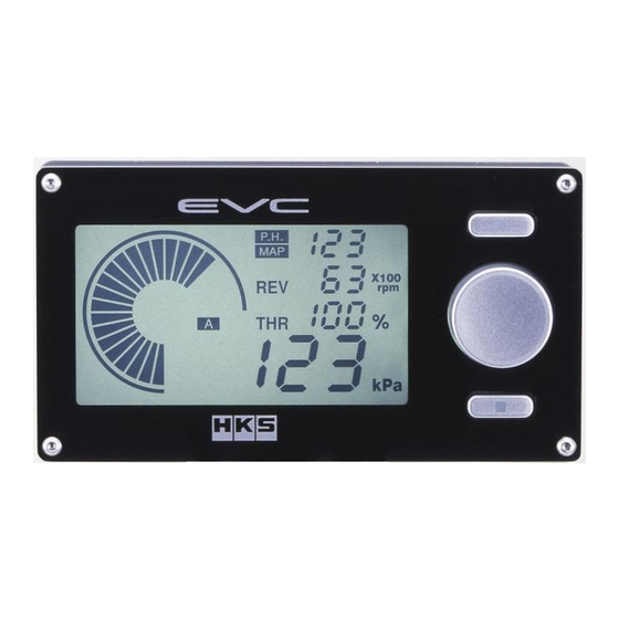
2.Display 2.1.Digital Display 1. Digital Display (S) 2. Speed / RPM Display 6. Indicator Display 3. Throttle Display 4. Unit Display 7. Bar Graph Display 5. Digital Display(L) 8. Selection Display 1. Digital Display(S) In this display, the preset warning value, preset A/B boost values, scramble countdown time, mode name, or wastegate type is shown. The pressure is shown as ○○○(kPa) or ○○.○(PSI), the scramble countdown time is shown as ○○(Sec), the mode name is shown as ○○○(MODE), and the wastegate type is shown as −○−. Standard Mode :Set Warning Value Standard Mode(A/BBoost Settings) :Preset A/BBoost Values Standard Mode(Scramble Function) : Scramble Countdown Time Each Setting Mode :Mode Name Opening Screen :Wastegate Type 2. Speed / RPM Display In this display, the value for each axis of the following mode is shown; Speed Axis Set Mode, RPM Axis Set Mode, Map Correction Boost A/B Set Mode and Map Offset A/B Set Mode. 3.… -
Page 12
7. Bar Graph Display In this display, a bar graph of the following can be shown: manifold pressure, speed, RPM, throttle percentage opening, set value, or axis number. In the Standard Mode, you can select between the manifold pressure, speed, RPM, and throttle percentage opening for real‑time display. 8. Selection Display The indicators of A and B show the selected preset boost setting in the Standard Mode. In the Offset A/B Set Mode, Map Boost A/B Set Mode and Map Offset A/B Set Mode, the current preset value is shown. The indicator of SPD, REV, and THR show the input signal currently used for the correction map in the Standard Mode, Map Boost A/B Set Mode and Map Offset A/B Set Mode. In the Speed Axis Grid Point Set Mode, RPM Axis Grid Point Mode and Throttle Axis Grid Point Set Mode, each corresponding signal is shown. 2.2.Start‑Up After the unit beeps once, the wastegate type appears on the digital display (S), and the preset boost value appears on the digital display (L). 2.3.Scramble Boost Activated After the unit beeps, the bar graph and the SBC indicator will blink. 2.4.Warning Function Triggered After the unit beeps, the bar graph and the WRN indicator will blink. Note ・The LCD of the display unit may have a black line. This is caused by static electricity, and it does not affect the functions or performance of the unit. To remove the line, wipe the display with an antistatic cloth or a cloth with the antistatic solution. www.R33-GTR.org −11−… -
Page 13: Installation
Installation 1. Removal of Battery Terminal …………………………………………………………………… 12 2. Hose Connection Layout 2.1. Stepping motor and 4mm Hose …………………………………………………………… 13 2.2. Swing Valve Type ………………………………………………………………………… 14 2.3. Poppet Valve Type ………………………………………………………………………… 18 2.4. Twin Turbo(Swing Valve) ……………………………………………………………… 20 2.5. 4mm Hose Connection Layout(Swing Valve) ………………………………………… 21 3. Wiring ……………………………………………………………………………………………… 23 4. Mounting of Components …………………………………………………………………………… 24 5. Post Installation ………………………………………………………………………………… 24 Warning ●This product was designed to be used with vehicles using a DC12V negative ground. Do not use on a vehilce with a 24V ground. ●This manual shows a typical installation. Actual installation may vary depending on the vehicle application. 1.Removal of Battery Terminal (1)Disconnect the negative terminal from the battery. 2.Hose Connection Layout (1)With consideration to the hose and harness lengths, determine the appropriate hose connection layout and mounting in regards to the display unit and stepping motor. Advice ・Leave some slack for the harness & hoses to avoid tension during engine movement. ・Do not install any components in high temperature areas. www.R33-GTR.org −12−…
-
Page 14: Stepping Motor And 4Mm Hose
Intake 4mm Hose Manifold Fuel Pressure Regulator (3)Cut a 5cm length portion of the included 4mm Hose 4mm hose and connect it the the T‑Fitting 5cm Length as shown in the diagram on the left. Intake 4mm Hose Manifold 4x4x4 mm T‑ Fitting Fuel Pressure Regulator (4)Use the remaining 4mm hose to connect the T‑Fitting to 4mm vacuum filter on Nipple B 4x4x4mm T‑Fitting of the EVC Stepping Motor. 4mm Vacuum Filter Intake Advice Manifold NippleB ・Make the hose length short as possible ・Do not put and oil and/or lubricants on or in the hose and vacuum filter Fuel Pressure Regulator ・Nipples of the EVC stepping motor must be 4mm Hose facing upward to avoid any oil or water from entering. EVC Stepping Motor www.R33-GTR.org −13−…
-
Page 15: Swing Valve Type
2.2.Swing Valve Type 2.2.1.For Applications without a Boost Solenoid Valve Before Installation(Basic Connection Layout) Airflow Meter Turbine Compressor Nipple① Actuator Air Filter Throttle Valve Intake Manifold 6mm Hose Fuel Pressure Regualtor After Installation Airflow Meter Turbine Compressor Nipple① Actuator Air Filter 4x4x4 mm Throttle Valve T‑Fitting Intake Manifold 6mm Hose 6mm Hose Vacuum Filter Fuel Pressure Regulator 4mm Hose EVC Stepping Motor www.R33-GTR.org −14−…
-
Page 16
(1)Remove the hose which connects the actuator Hose Clamp and Nipple① from the compressor side. Nipple① Note ・The position of Nipple① on the compressor may vary depending on vehicle. ・Reuse the factory hose clamp. Actuator Hose Clamp (2)Connect Nipple① and the EVC Stepping 6mm Hose Motor’s 6mm vacuum filter using the Hose Clamp 6mm Vacuum Filter Nipple① included 6mm hose. EVC Stepping Motor (3)Connect the factory hose, which is still connected to the actuator, to the EVC Stepping Motor’s NippleO. Hose Clamp NippleO Factory 6mm Hose Advice ・Do not put any oil and/or lubricants on or in the hose and vacuum filter. ・Use the hose clamp to connect the 6mm hose and the 6mm vacuum filter. ・If the factory hose’s length is not long enough to connect, use the optional oil‑resistant hose. This optional oil‑resistant hose is available separately. (Refer to the Optional Parts list in this manual) www.R33-GTR.org −15−… -
Page 17
2.2.2.For Applications with a Boost Control Solenoid ‑ 1 ●Bypass the function of the boost control solenoid valve by removing the connector or hose. Before Installation(Basic Connection Layout) Airflow Meter Turbine Compressor Actuator Air Filter Throttle Valve Boost Control Intake Solenoid Valve Manifold 6mm Hose Fuel Pressure Regulator After Installation Airflow Meter Rubber Cap Turbine Boost Control Compressor Solenoid Valve Actuator Air Filter 4x4x4 mm Throttle Valve T‑Fitting Intake Manifold Rubber Cap 6mm Hose 6mm Hose Vacuum Filter Fuel Pressure Regulator 4mm Hose EV C Stepping Mot or www.R33-GTR.org −16−… -
Page 18
2.2.3.For Applications with a Boost Control Solenoid Valve ‑ 2 ●Bypass the function of the boost control solenoid valve by removing the connector or hose. Before Installation(Basic Connection Layout) Airflow Meter Turbine Compressor Actuator Air Filter Throttle Valve Intake Manifold 6mm Hose Boost Control Solenoid Valve Fuel Pressure Regulator After Installation Airflow Meter Rubber Cap Turbine Compressor Actuator Air Filter Rubber Cap 4x4x4 mm Throttle Valve T‑Fitting Intake Manifold 6mm Hose 6mm Hose Boost Control Vacuum Filter Solenoid Valve Fuel Pressure Regulator 4mm Hose EVC… -
Page 19
2.3.Poppet Valve Type To install this unit on to a poppet valve equipped vehicle, the hose set for the poppet type is necessary. Before Installtion Airflow Meter Turbine Upper Port Compressor Air Filter Throttle Valve Intake Manifold 8mm Hose Wastegate Fuel Pressure Regulator After Installation Airflow Meter Turbine Wastegate Compressor Attach nipple (L or straight nipple) Air Filter to upper 6x8x6mm T‑Fitting port 4x4x4 mm Throttle Valve Intake T‑Fitting Mainfold 6mm Hose 6mm Hose 6mm Hose Vacuum Filter Fuel Pressure Regulator 4mm Hose E V C Stepping Motor www.R33-GTR.org −18−… -
Page 20: Poppet Valve Type
(1)Cut the 8mm hose at the point of 5cm from Nipple① the compressor’s Nipple①. Remove the remaining 8mm hose and 8mm nipple from the Cut Here wastegate. 5cm Length Note ・The position of Nipple① on the compressor Wastegate may vary depending on the vehicle. (2)Install the 6x8x6mm T‑Fitting using the 8mm Hose Clamp. Nipple① Note ・Use the 6x8x6mm T‑Fitting and 8mm Hose Clamp included in the hose kit for the 6x8x6 mm T‑Fitting poppet valve type applications. (3)Connect the 6mm Vacuum Filter of the EVC Stepping Motor’s NippleⅠ to the T‑Fitting using the 6mm hose. Hose Clamp Advice 6mm Hose ・Do not put any oil and/or lubricants on or in the hose or vacuum filter. 6mm Vacuum Filter NippleⅠ (4)After removing the 8mm nipple from the Hose Clamp wastegate, install the 6mm nipple (straight 6mm Hose or L‑Shaped). (5)Install the included 6mm hose as shown in the diagram on the left. 6mm Nipple Note ・Use the hose clamp to connect the 6mm hose and the 6mm nipple.
-
Page 21
(6)Install the 6mm nipple to the wastegate’s upper port. 6mm Nipple (7)Using 6mm Hose, connect the EVC Stepping Motor’s NippleO to the 6mm nipple installed on the wastegate in step #(6). 6mm Hose NippleO 2.5.Twin Turbo Applications (Swing Valve Type) To install this unit on to a twin turbo vehicle, the hose set for the twin turbo vehicle is needed. The basic hose layout procedure is similar as the swing valve. (1)Remove the factory hoses between each turbocharger’s compressor and actuators. Remove These Actuators (2)Connect the actuators of each of the two turbochargers using 6mm hose. (3)Connect each compressor of the two turbochargers using 6mm hose. 6mm Hose Advice Actuators ・Use the 6mm hose and 6mm hose clamps. (4)Cut the center of each of the 6mm hoses and and insert a 6x6x6 T‑Fitting in each. Advice 6mm Hose 6mm Hose ・Use 6mm hose clamps to secure hoses. 6x6x6 mm T‑Fitting Actuator www.R33-GTR.org −20−… -
Page 22
(5)Follow the instructions of Section 2.2 Swing Valve Type for remaining steps. EVC Stepping Motor 4mm Hose 6mm Vacuum Filter 4mm Vacuum Filter 6mm Hose Twin Turbo Application Sample 2.5.4mm Hose Layout Application To install this unit on a 4mm hose equipped vehicle, the 4mm hose set is needed. The basic hose layout procedure is the same as for the swing valve type. Airflow Meter Turbine Compressor Actuator Air Filter 4mm→ ← 6mm Hose Throttle Valve 4x4x4 Adapter Intake 4mm Hose T‑Fitting Manifold 6mm Hose 6mm Hose 4mm Hose Vacuum Filter 4mm←6mm Hose Adapter Fuel Pressure Regulator 4mm Hose EVC Stepping Motor (1)Use the 4mm hose included in the 4mm hose set instead of the included 6mm hose on points where the 6mm hoses are supposed to be used. (2)Connect the 6mm hose to the 6mm vacuum filter using the 4mm‑6mm adpater included included in the 4mm hose set. Advice ・Use the 6mm hose included in this product. -
Page 23
〜MEMO〜 www.R33-GTR.org −22−… -
Page 24: 3.2. Wiring
electrical tape to insulate. Insulate with electrical tape 3.2. Wiring Vehicle Interior Engine Compartment EVC Display Unit EVC Stepping Motor Throttle Input Signal (Blue) Speed / RPM Input Signal (White) 5 PIN Connector (White) 4 PIN Connector (White) Extension Harness Main 5 PIN Connector Harness Power Harness (Black) Scramble Harness (1)Pull the white connector of the Extension Harness from the engine compartment into the vehicle interior and connect it to the 5 PIN connector of the EVC Main Harness. (2)Connect the Extension Harness to the 5 PIN Connector of the EVC Stepping Motor. (3)Connect the EVC Main Harness to the 3 PIN Connector of the Display Unit. (4)Connect the red wire of the Power Harness to the ignition wire using a splice. (a)Reconnect the negative battery cable to the battery terminal. (b)Turn the ignition switch on and find the wire generating 12v using a test light. (c)Remove the negative battery cable from the terminal of the battery. (5)Confirm the locations of the throttle signal line and the engine RPM signal line or the speed signal line of the vehicle’s harness that connects to the ECU. Connect the blue wire of the Input Signal Harness to the throttle signal line, and the white wire to the engine RPM signal line or the speed signal line using splices. Refer to the factory service manual for signal line locations. Advice ・If a speed limiter release device such as the HKS SLD is already installed on the vehicle, connect the white wire of the input signal harness to the side towards the vehicle’s harness from the device. ・Do not connect unused signal lines. (6)Connect each input signal wire to the same colored wires on the Main Harness. (7)Connect the ground wire (Black). www.R33-GTR.org…
-
Page 25: Mounting Of Components
Advice ・Rub off any paint and/or rust of the surface where the ground wire is connected. (8)Connect the 4 PIN Connector of the Main Harness to the Power Harness. Note ・When utilizing an external switch for the Scramble Boost activation, connect the two wires (blue and white) of the scramble harness to a momentary switch in the form that when the switch is triggered a closed‑circuit is made. 4.Mounting of Components 4.1.Mounting the Display Unit (1)Remove any dirt, dust and/or oil from the EVC Display Unit (Rear) area the unit is going to be mounted to. (2)Secure the display unit using the included double‑side tape. Advice Double‑Stick Tape ・The display was designed to have the best visibility when it is looked at downward. It is recommended to mount the display unit to a position where it is lower than your eyes or mount the unit facing upwards. 4.2.Mounting the Stepping Motor (1)Mount the Stepping Motor using the M6 Nipple bolt and nut. EVC Stepping Motor M6 4.3.Securing the Hose and Harness (1)Secure hoses and harnesses using the included tie‑wraps. Advice ・Leave slack in the hose and harness to absorb engine vibration and movement. 5. Post Installation (1)Reinstall all removed factory parts. (2)Reconnect the negative battery cable to the battery terminal. www.R33-GTR.org −24−…
-
Page 26: Post Installation Checks
Post Installation Checks Check the following after the installation processs is complete. 1. Check the following BEFORE starting the engine Items to check Checked Make sure all hoses are routed and connected correctly. Make sure all hoses do not have too much slack. Make sure all hoses are not damaged. Make sure all hose clamps are secure and tight Make sure all bolts and nuts are properly tightend. Make sure hoses, harnesses & installed components do not contact other parts. Make sure hoses and harnesses are secured properly. Make sure wiring is done correctly. Make sure all connectors and splices are connected securely. Make sure all splices are the included ones and stalked properly. Make sure the unit or components are mounted securely and dont disturb driving. Make sure the negative cable terminal is securely attached to the battery. Make sure the boost control solenoid valve is bypassed. 2. Check the following AFTER starting the engine Advice ・Do not raise the engine RPM right after staring engine. (Let it idle) Items to check Checked Make sure there is no air leakage. Make sure there is no air leakage after revving the engine in neutral 2‑3 times. Make sure installed parts are not in contact with each other. Make sure there is no excessive stress on hoses or harnesses. Make sure there are no parts that have loosened after stopping the engine. www.R33-GTR.org −25−…
-
Page 27: Operation
Operation 1. Operation Outline ……………………………………………………………………………………27 2. Initial Set‑Up…………………………………………………………………………………………29 3. Standard Mode 3.1. Boost Control ……………………………………………………………………………… 31 3.2. Peak Hold …………………………………………………………………………………… 31 3.3. Scramble …………………………………………………………………………………… 31 4. Basic Settings Group 4.1. Offset A Set Mode / Offset B Set Mode …………………………………………… 32 4.2. Scramble Boost Set Mode ………………………………………………………………… 32 4.3. Scramble Time Set Mode…………………………………………………………………… 32 4.4. Warning Boost Set Mode…………………………………………………………………… 33 4.5. Drop Boost Set Mode ……………………………………………………………………… 33 5. Map Setting Group 5.1. Map Functions Set Mode…………………………………………………………………… 34 5.2. Speed Axis Grid Point Set Mode………………………………………………………… 34 5.3. RPM Axis Grid Point Set Mode…………………………………………………………… 35 5.4. Throttle Axis Grid Point Set Mode …………………………………………………… 35 5.5. Boost Map Correction A Set Mode / Boost Map Correction B Set Mode ……… 36 5.6. Offset Map A Set Mode / Offset Map B Set Mode ………………………………… 37 6. Function Setting Group 6.1. Bar Graph Function Set Mode …………………………………………………………… 38 6.2. Bar Graph Maximum Value Set Mode……………………………………………………… 38 6.3. Backlight Brightness Set Mode ………………………………………………………… 39 6.4. After Image Set Mode……………………………………………………………………… 39 6.5. Bar Graph Peak Set Mode ………………………………………………………………… 40 6.6. Data Lock Set Mode………………………………………………………………………… 40 7. Vehicle Setting Group 7.1. Cylinder # Set Mode ……………………………………………………………………… 41 7.2. Speed Pulse Set Mode……………………………………………………………………… 41 7.3. Throttle‑Off Voltage Set Mode ………………………………………………………… 42 7.4. Full Throttle Voltage Set Mode………………………………………………………… 42 7.5. Sampling Rate Set Mode…………………………………………………………………… 43 7.6. All Reset Mode……………………………………………………………………………… 43 www.R33-GTR.org −26−…
-
Page 28: Operation Outline
1.Operation Outline Ignition ON (Ref. page 29) Initial Set‑Up First Use / After All Reset Standard Mode Post Initial Set‑Up (Ref. page 31) A Mode B Mode Turn Knob ① or External Scramble Switch Target Boost Setting: Short Power ON/OFF : ② Long Peak Value Reset: Long ② Short ② Short ② Short Offset A Set Mode Map Function Set Mode Turn Turn Offset B Set Mode Speed Axis Grid Point Set Mode Turn Turn Scramble Boost Set Mode RPM Axis Grid Point Set Mode Turn Turn Scramble Time Set Mode Throttle Axis Grid Point Set Mode Turn Turn…
-
Page 29: Bar Graph Function Set Mode
Button① ※ Operational Diagram Volume Knob ① :Button① :Button② ② Button② :Volume Knob After Scramble Countdown Scramble ② Short ② Short Bar Graph Function Set Mode Cylinder # Set Mode Turn Turn Bar Graph Max Value Set Mode Speed Pulse Set Mode Turn Turn Backlight Brightness Set Mode Throttle‑Off Set Mode Turn Turn After Image Set Mode Full Throttle Set Mode Turn Turn Bar Graph Peak Set Mode Sampling Rate Set Mode Turn Turn Data Lock Set Mode All Reset Mode Vehicle Setting Group Function Setting Group (Ref. page 38)…
-
Page 30
2.Initial Set‑Up Initial Set‑Up Configuration: unit of measure for pressure, wastegate type,and target boost. The characteristics of the boost change for each vehicle can be memorizedby the EVC. When using the EVC for the first time (or after a reset) the initial set‑up will be automatically started. Follow the procedure below for the initial setting. Action Key :Press and hold for 1 sec. :Press :Turn Volume 2.1.Setting the Pressure Unit of Measure (1)Turn the volume knob and select the pressure unit of measure from «PAS (kPa)» or «PSI.» ・The digital display (S) will display » «. (2)Press the volume knob after selecting the unit, Go to 2.2 for setting the exhaust bypass (wastegate) type. 2.2.Setting the Exhaust Bypass Type For most factory turbo applications, the actuator type is used; therefore, the exhaust bypass type is the swing valve type. For most large capacity turbo applications, the external wastegate is used; therefore, the exhaust bypass type is the poppet valve type. (1)Turn the volume knob and select the exhaust bypass type from «‑S‑» for the swing valve type or «‑P‑» for the poppet valve type. ・The digital display (S) shows » «. (2)Press the volume knob after selecting the exhaust bypass type. Go to 2.3 for setting the standard max boost setting. 2.3.Setting the Standard Maximum Boost Setting The maximum baseline/default boost after installing the EVC. (1)Turn the volume knob and set the max baseline / default boost value if the boost value is known. If not, drive the vehicle under load to achieve the maximum boost value. The value will then be shown in the digital display (S). ・The speed/RPM display shows » «. ・The digital display (L) shows the current boost value. ・Enter the max boost value that is stable. (2)Press the volume knob when the digital display (S) is showing the max baseline/default boost value. Go to 2.4 for setting the target boost. -
Page 31
・The target value is for both A & B boost settings. ・Changes to target boost for both A & B modes can made in the Standard Mode after completing the initial setting. (2)Press the volume knob after setting the target boost. Go to 2.5 for setting the correction coefficient. 2.5.Setting the Correction Coefficient If the target cannot be achieved, increase or decrease the correction coefficient to adjust the boost to the target value. (1)Ensure the display is as shown in the illustration on the left. Drive the vehicle to reach the max boost. If the target boost and the actual max boost do not match, turn the volume until the actual max boost reaches to the target boost. ・The speed/RPM display shows » «. ・Increasing the correction coefficient raises boost and decreasing the coefficient reduces boost. ・The digital display(S) shows the peak hold value and the digital display (L) shows the current boost value. (2)Press the volume knob after setting the coefficient. This completes the initial setting. Go to 3 for the standard mode. Note ・For the vehicle equipped with the boost solenoid valve, after installing the EVC, the standard max boost will be lower than the boost before installing the EVC. ・In the below cases, the max boost cannot reach 250kPa: (a)The set load (spring’s force) of the wastagate’s valve or actuator is too low. (b)The exhaust back pressure is creating a resistance. ・In the below cases, the boost cannot be stabilized: (a)Wastegate’s valve area and/or its stroke in not sufficent. Or, the boost creep or drop is due to the actuator incapacity. (b)Turbo air volume is not sufficent for the engine displacement. Or, the boost creep or drop is due to an increase in the exhaust pressure. Therefore, conditions and specifications of the vehicle must be examined carefully before installing the EVC. ・Refer to the following procedures for the setting range of each value. Stable Boost www.R33-GTR.org −30−… -
Page 32
3.Standard Mode 3.1.Boost Control Set the boost values for A/B modes in the Standard Mode. (1)In the Stanards Mode, press the volume knob to set ・The EVC will beep and P. H. will illuminate; the digital display (S) changes from peak hold display to the blinking target boost value. ・»SET» will also illuminate. ・To set value for B Mode, select B Mode with the volume knob (turn right), then press knob. (2)Turn the volume knob to set the target boost value. When the value is selected, press the volume knob again. ・The EVC will beep and the displays returns to peak hold display. ・The selection range is from baseline boost to 250kPa / 36.0 PSI. ・The target boost value set in the initial setting is the default value for booth A & B Modes. (3)To turn the EVC off, press Button② for more than 1 second. Repeat set to turn the EVC on. ・An audible beep will be emitted to confirm action. ・When the EVC is off, the current boost reading and the Peak Hold value will be the only data displayed. 3.2.Peak Hold While the EVC is in the Standard Mode, the maximum boost is displayed and automatically updated in the digital display (S), denoted with the P.H illumination. To reset value: (1)Press the volume knob for more than 1 second ・The peak hold value will cleared and reset to 0 kPa or 0.0 PSI accordingly. 3.3.Scramble Activate the Scramble boost function by pressing Button① or the external scramble switch. (1)After pressing Button① or the external scramble to trigger its activation, the EVC will. ・Beep to indicate that the function is active. ・The bar graph and «SBC» will blick and the remaining time of the scramble will be displayed on the digital display (S). ・When using the user preset time function of the Scramble, the countdown does not begin until the… -
Page 33
4.Basic Settings Group 4.1.Offset A Set Mode / Offset B Set Mode Adjust the boost’s gain or stability for both A and B Modes. (1)Press the volume knob in the Offset A Set Mode or Offset B Set Mode. ・The digital display (S) will display [ ]. ・The EVC will beep and the digital display (L) blinks. ・»SET» will appear in the display. ・The left illustration references Offset A Set Mode. (2)Turn the volume knob and set the Offset A and B value. When the settings are done, press the volume knob. ・The setting range is between 1‑199% in 1% increments. ・The default setting value is 100%. ・The boost will rise when the set value is increased and vice versa. This applies to both wastegate type selections. 4.2.Scramble Boost Set Mode Set the boost value to be added to the target boost when the Scramble function is triggered. (1)Press the volume knob while in the Scramble Boost Set Mode. ・Digital Display (S) will illuminate [ ]. ・»SBC» will be illuminated on the display. ・The EVC will beep and the digital display (L) blinks. ・»SET»will be illuminated on the display. (2)Turn the volume knob to select the amount of additional boost for the Scramble function. After the selection, press the volume knob to set. ・The setting range is between 0‑120 kPa or 0.0‑17.0 PSI respectively for the unit of measure selected. ・The default setting is 0 kPa or 0 PSI. 4.3.Scramble Time Set Mode Set the time duration of the added Scramble boost for when the Scramble is triggered. (1)Press the volume knob while in the Scramble Time Set Mode. ・The digital display (S) will illuminate [ ] ・»SBC» will be illuminated on the display. ・The EVC will beep and the digital display (L) blinks. ・»SET»will be illuminated on the display. www.R33-GTR.org −32−… -
Page 34
(2)Turn the volume knob to select the duration of Scramble Time. After selection is done, press the volume knob. ・The setting range is between 0‑60 seconds in 1 second increments. ・The default setting is 0 seconds. Note ・While pressing Button①, the Scramble function is activated. However, the Scramble timer function will not countdown until after the release of the button. When the Scramble time is set to 0 second, the Scramble function is only active when the button is pressed. 4.4.Warning Boost Set Mode The warning function is activated when the manifold pressure goes exceeds the user preset boost value. The EVC will drop boost to baseline boost or by a user set amount of boost. (1)While in the Warning Boost Set Mode, press the volume knob. ・The digital display (S) will illuminated [ ]. ・»WRN» will be illuminated on the display. ・The EVC will beep and the digital dusplay (L) blinks. ・»SET» will be illuminated on the display. (2)Turn the volume knob to select the warning boost value. After value has been selected, press the volume knob. ・The setting range is 0‑250 kPa or 0.0‑36 PSI in increments of 1kPa or 0.1 PSI respectively. ・The default setting value is 250 kPa or 36.0 PSI. Note ・The warning function is reset when the manifold pressure drops below 5 kPa. 4.5.Drop Boost Set Mode Set the amount of boost to drop when the warning function is triggered. (1)While in the Drop Boost Mode, press the volume knob. ・The digital display (S) will illuminated [ ]. ・»WRN» will illuminate on the display ・The EVC will beep and the digital display (L) blinks. ・»SET» will illuminate on the display. (2)Turn the volume knob to select the value amount of boost drop. After selections, press volume knob. ・The setting range is 1‑120 kPa or 0.1‑17.0 PSI in increments of 1kPa or 0.1 PSI respectively ・The default setting is «OFF». (Drops boost to the baseline boost value) www.R33-GTR.org… -
Page 35
5.Map Setting Group 5.1.Map Functions Set Mode Select the input signal(s) for the Boost Correction Map. (1)Press the volume knob while in the Map Function Set Mode. ・The digital display (S) will illuminate [ ]. ・The EVC will beep and the digital display (L) blinks. ・»SEL» will illuminate on the display. (2)Turn the volume knob to select input signal function. After selectioning, press the volume knob. ・1:OFF (No Map) 2:Throttle Correction(THR) 3:RPM Correction(REV) 4:Speed Correction(SPD) 5:REV+THR 6:SPD+THR ・The default setting is 1 ・The illustration on the left shows setting 5:REV +THR Note ・In the Standard Mode display, only the selected input signal is shown. 5.2.Speed Axis Grid Point Set Mode Change the speed axis grid point (division point of the map by speed) for the map. (1)Press the volume knob while in the speed axis grid point set mode. ・The digital display (S) will illuminate [ ]. ・The EVC will beep and the digital display (L) blinks. ・»SEL» will illuminate on the display. ・The displayed speed value is 1/10th of actual speed. ・There are 5 sequential grid points; «1» is the lowest and «5» is the highest. (2)Turn the volume knob to select the grid point to change. Press the Button① to change the speed value. ・When the grid point is changed, the speed setting display is also changed. ・Pressing Button① advances to step(3). «SEL» will disappear as «SET» will appear. The digital display (L) stops blinking and the speed display will then blink. (3)Turn the volume knob and change the speed corresponding to the grid point. When the setting is done, press the volume knob again. ・To change other speed settings, press Button① and go back to step(2) and repeat procedure. -
Page 36
Note ・The default grid point settings are as follows: 1: 0 km/h, 2: 50km/h, 3: 100km/h, 4: 150km/h and 5: 200km/h. ・The value setting range is between 0‑500km/h. Each grid point setting value should be +10 km/h of the previous grid point and ‑10km/h of the next point. 5.3.RPM Axis Grid Point Set Mode Change the RPM axis grid point (division point of the map by RPM) for the map. (1)Press the volume knob while in the RPM axis grid point set mode. ・The digital display (S) will illuminate [ ]. ・The EVC will beep and the digital display (L) blinks. ・»SEL» will illuminate. ・The displayed RPM value is 1/100 of the actual RPM. ・There are 5 sequential grid points; «1» is the lowest and «5» is the highest. (2)Turn the volume knob to select the grid point to change. Press Button① to change the RPM. ・When the grid point is changed, the RPM setting display is also changed. ・Pressing Button① advances to step(3). «SEL» will disappear as «SET» will appear. The digital display (L) stops blinking & the RPM setting display will blink. (3)Turn the volume knob and change the RPM corresponding to the grid point. When the setting is done, press the volume knob again. ・To change the other RPM settings, press Button① and go back to step(2) and repeat procedure. Note ・The default grid point settings are as follows: 1: 2000rpm, 2: 3000rpm, 3: 4000rpm, 4: 5000rpm, 5: 6000rpm. ・The RPM setting range is between 0‑12000rpm. Each grid point setting value should be +100rpm of the previous grid point and ‑100rpm of the next point. 5.4.Throttle Axis Grid Point Set Mode Change the throttle axis grid point (division point of the map by throttle opening %) for the map. (1)Press the volume knob while in the RPM axis grid point set mode. ・The digital display (S) will illuminate [ ]. ・The EVC will beep and the digital display (L) blinks. ・»SEL» will illuminate. -
Page 37
(2)Turn the volume knob to select the grid point to change. Press Button① to change the throttle opening ratio. ・When the grid point is changed, the throttle setting display is also changed. ・Pressing Button① advnaces to step(3).»SEL» will disappear as «SET» appears on the display. The digital display (L) stops blinking and the throttle setting will blink. (3)Turn the volume knob and change the throttle opening % corresponding to the grid point. When the setting is done, press the volume knob again. ・To change other throttle seetings, press Button① and and go back to step(2) and repeat procedure. Note ・The default grid point settings are as follows: 1: 0%, 2: 25%, 3: 50%, 4: 75%, 5: 100% ・The throttle % setting range is between 0‑100%. Each grid point setting value should be +1% of the previous grid point and ‑1% of the next grid point. 5.5.Boost Map Correction A Set Mode / Boost Map Correction B Set Mode Set the boost map correction value to calculate the correction boost corresponding to the throttle and speed or RPM input for both Boost A/B modes. (1)Press the volume knob in the boost map correction A set mode or B set mode. ・The digital display (S) will illuminate [ ]. ・The EVC will beep and the digital display (L) blink. ・»SET» will illuminate. ・The image on the left represents the map offset A mode when the map function mode «5» (REV=THR) is selected. (2)Turn the volume knob to set the correction boost. When settings are complete, press the volume knob again. ・Press Button① to change the correction boost value for other axes. ・Pressing Button① advances to step(3). «SEL» will appear as «SET» disappears. The digital display (L) stops blinking and the throttle % value blinks. (3)Turn the volume knob to move the throttle opening axis. Pressing Button① will move to the RPM Axis ・Pressing Button① advances to step(4). The throttle % value turns constant and the RPM value blinks. www.R33-GTR.org −36−… -
Page 38
(4)Turn the volume knob to move the RPM axis. Pressing Button① will return to the correction boost default. ・Pressing Button① will revert to step(2). The RPM value will become constant and the digital display (L) will then blink. ・When all settings are done, press the volume knob. Note ・The default correction boost value for all map grid points is ±0 kPA or ±0 PSI. ・The setting range must be within ‑120 kPa 〜 120 kPa or ‑17.0 PSI 〜 17.0 PSI. ・Avoid large value gaps between the sequential map grid points to prevent boost control instability. 5.6.Offset Map A Set Mode / Offset Map B Set Mode Generally not need, but precise adjustments for the set boost value of each A/B set modes corresponding to the throttle opening % and the engine RPM or speed can be done here. (1)Press the volume knob in the offset map A set mode or B set mode.。 ・The digital display (S) will illuminate [ ]. ・The EVC will beep and the digital display (L) blinks. ・»SET» will illuminate ・The image on the left represents the map offset A mode when the map function mode «5» (REV=THR) is selected. (2)Turn the volume knob to set the map offset value. When the setting is done, press the volume knob again. ・Press Button① to change the map offset value for other axes. ・Pressing Button① advances to step(3). «SET» will appear as «SEL» disappears. The digital display (L) will stop blinking and the throttle display blinks. (3) Turn the volume knob to move the throttle axis. Pressing Button① moves the RPM axis. ・Press Button① to advance to step(4). The throttle display becomes constant and the RPM value will blink (4)Turn the volume knob to move the RPM axis. Pressing Button① will return you to the default map offset mode ・Pressing Button① will revert to step(2). The RPM value will become constant and the digital display (L) will then blink. ・When all settings are done, press the volume knob Note ・The default value for all map grid points are 100%. -
Page 39
6.Function Setting Group 6.1.Bar Graph Function Set Mode Select the data to be displayed in the bar graph while in the standard mode. (1)Press the volume knob in the bar graph function set mode. ・The digital display (S) will illuminate [ ]. ・The EVC will beep and the digital display (L) Blinks ・»SEL» will illuminate. (2)Turn the volume knob to select the data function to be displayed. Press volume knob to complete setting. ・Select from the following 5 data functions: bST / bST / SPd / REV / THR ・The default setting is bST . Note ・ A ‑ Bar graph display range is between ‑100 to 250 kPA or bST : Boost Display ‑14.0 to 36.0 PSI. ・ B ‑ Bar graph display range is between ‑100 to 250 kPA or bST : Boost Display ‑14.0 to 36.0 PSI. ・ Speed Display ‑ Bar graph display is between 0 to 50 x 10km/h. SPd: ・REV: Engine RPM Display ‑ Bar graph display range is between 0 to 120 x 100rpm. ・THR: Throttle % Opening Display ‑ Bar graph display range is between 0 to 100%. 6.2.Bar Graph Maximum Value Set Mode Set the maximum value of the bar graph in the standard mode. (1)Press the volume knob in the bar graph max value set mode. ・The digital display (S) will illuminate [ ]. ・The EVC will beep and the digital display (L) Blinks ・»SET» will illuminate. (2)Turn volume knob and select the max value to be displayed on the bar graph. When selection is done, press the volume knob again. ・The image on the left represents the bST setting with 160 kPa selected. … -
Page 40
Note ・The maximum values for each selection are as follows: bST /bST ‑ 250kPa or 36.0 PSI、SPd‑ 50x 10km/h、REV‑ 120x 100rpm、 THR‑ 100%. ・The minimum value of the bar graph function set mode is «0» ・The default setting is the maximum value of each respective selection. 6.3.Backlight Brightness Set Mode Setting the backlight’s brightness. (1)Press the volume knob while in the backlight brightness set mode. ・The digital display (S) will illuminate [ ]. ・The EVC will beep and the digital display (L) blinks. ・»SET» will illuminate on the display. (2)Turn the volume knob to set the backlight’s brightness. After your selection, press the volume knob again. ・The setting range is between 1‑100% in 1% increments. ・The default setting is 100%. ・The lower the %, the dimmer the text will display. Note ・This function is not linked to the vehicle’s headlight illumination or dimmer system. 6.4.After Image Set Mode This mode is to set the digital display (L) to blink and show the max boost achieved for 3 seconds when the boost changes from positive pressure to negative pressure. (1)Press the volume knob while in the after image set mode. ・The digital display (S) will illuminate [ ]. ・The EVC will beep and the digital display (L) blinks. ・»SEL» will illuminate on the display. (2)Turn the volume knob to set the function ON or OFF. When the selection has been made, press the volume knob. ・The default setting is OFF. www.R33-GTR.org −39−… -
Page 41
6.5.Bar Graph Peak Set Mode Set the bar graph to display the peak value. (1)Press the volume knob while in the bar graph peak set mode. ・The digital display (S) will illuminate [ ]. ・The EVC will beep and the digital display (L) blinks. ・»SEL» will illuminate on the display. (2)Turn the volume knob to set the function ON or OFF. When the selection has been made, press the volume knob. ・The default setting is OFF. Note ・When the bar graph display value decreses, the bar point of the maximum value remains. ・When bST or bST is selected, only the maximum positive pressure bar point is lit. 6.6.Data Lock Set Mode. Set the data lock function with a personal code number to prevent any changes to the settings. (1)Press the volume knob while in the data lock set mode. ・The digital display (S) will illuminate [ ]. ・The EVC will beep and the digital display (L) blinks. ・»SEL» will illuminate on the display. ・The digital display (L) will display the following: »0000» : No lock number is set. «−−−−» : Lock number is set. (2)Turn the volume knob to set the code number. When the code is selected, press the volume knob again to set. ・Enter the 4 digit number you would like as the code. ・To unlock, enter in the 4 digit code. ・The default setting is 0000. Note ・The data lock function pertains to set data in the basic setting, the map setting, and the vehicle setting groups. ・If the code number is lost for forgotten, you will need to reset the EVC accordinly to the procedures in 7.5 All Reset Mode. Please note that an All Reset will clear all inputted settings and the EVC’s initial setup will need to be redone. www.R33-GTR.org −40−… -
Page 42
7.Vehicle Setting Group For optimum performance of the EVC, select the appropriate selects for the application. CAUTION ● Settings must be done with the engine OFF. 7.1.Cylinder # Set Mode Set the amount for the number of cylinders of engine. (For use for the RPM signal input) (1)Press the volume knob while in the cylinder # set mode. ・The digital display (S) will illuminate [ ]. ・The EVC will beep and the digital display (L) blinks. ・»SEL» will illuminate on the display. (2)Turn the volume knob to select the number of cylinders. Press the volume knob after the selection. ・Select from:1・2・3・4・6・8 of cylinders. ・The default setting is «4» for 4 cylinders. Note ・For rotary engines, select «4» for 2rotor engines and «6» for 3rotor engines. 7.2.Speed Pulse Set Mode Set the speed pulse for the speed signal input. (1)Press the volume knob while in the speed pulse set Mode. ・The digital displau (S) will illuminate [ ]. ・The EVC will beep and the digital display (L) blinks. ・»SEL» will illuminate on the display. (2)Turn the volume knob to select the speed pulse setting. Press the volume knob after the selection. ・Select from: 2・4・8・16 pulses. ・The default setting is «4» pulses. Note ・For Nissan Y32 Gloria / Cedric use setting 16, for Y32 Cima use setting 8 and for www.R33-GTR.org all other Nissan vehicles use setting 2. For other JDM vehicles use setting 4. −41−… -
Page 43
7.3.Throttle‑Off Voltage Set Mode To use the throttle signal input of the EVC, you must set the Throttle‑Off voltage value. (1)Press the volume knob while in the Throttle‑Off set mode. ・The digital display (S) will illuminate [ ]. ・The EVC will beep and the digital display (L) blinks. ・»SET» will illuminate on the display. (2)The current throttle voltage is displayed. When the icon is illuminated, the voltage will be automatically determined. To ensure that the throttle is completely closed, step on the accelerator pedal and then release. After confirming that it is closed, press the volume knob to set the value. ・The EVC will beep and the voltage value is now set. (3)The throttle‑off voltage value can also be manually inputted. Press Button① and the icon will now illuminate, indicating you are in manual mode. Turn the volume knob to select the closed voltage and press the volume knob to set. ・The EVC will beep and the voltage value is now set. Note ・The default value is 0. 50V. 7.4.Full Throttle Voltage Set Mode To use the throttle signal input of the EVC, you must set the Full Throttle voltage value (1)Press the volume knob while in the Full Throttle set mode. ・The digital display (S) will illuminate [ ]. ・The EVC will beep and the digital display (L) blinks. ・»SET» will illuminate on the display. (2)The current throttle voltage is displayed. When the icon is illuminated, the voltage will be automatically determined. With the engine OFF, firmly step on the accelerator pedal until it reaches the stopper. After confirming that it is fully open, press the volume knob to set the value. ・The EVC will beep and the voltage value is now set. www.R33-GTR.org −42−… -
Page 44
(3)The full throttle voltage value can also be manually inputted. Press Button① and the icon will now illuminate, indicating you are in manual mode. Turn the volume knob to select the open voltage and press the volume knob to set. ・The EVC will beep and the voltage calue is now set. Note ・The default value is 4. 50V. 7.5.Sampling Rate Set Mode Generally not needed, but the sampling rate mode of the stepping motor can be adjusted if boost value is unstable and fluctuating above and below the target boost value. (1)Press the volume knob while in the Sampling Rate Set Mode. ・The digital display (S) will illiminate [ ]. ・The EVC will beep and the digital display will blink. ・»SEL» will illuminate on the display. (2)Turn the volume knob to select the sampling rate value. After selection has been made, press the volume knob to set value. ・Select from 1・2・3・4・5 sampling rates. ・The default setting is sampling rate 4. 7.6.All Reset Mode Reset all user set values to the default setting values. (1)Press the volume knob for more than 1 second while in the all reset mode. ・The digital display (S) will illuminate [ ]. ・The EVC will beep and the digital display (L) blinks. ・»SEL» will illuminate on the display. (2)Turn the volume knob to select «YES» or «NO». When the selection is made, press the volume knob to set. ・When selecting «NO», reset is NOT done and the digital display (L) stops blinking. ・When selecting «YES», all user set values are reset to default setting values. Following this step, go back to section 2 to redo the intial setup. Note ・Use this mode to reset initial settings or when the lock code is lost or forgotten. www.R33-GTR.org −43−… -
Page 45: Optional Parts List
Optional Parts List Below is a list of universal option parts. For additional items and vehicle specific EVC install kits, contact your authorized HKS dealer or www.hksusa.com/evccomponents. Part No. Description Remarks 1 HKS Easy Writer Software 2 90461‑010004 6mm Hose 1 ft. increments 1 ft. increments 3 90461‑010006 4mm Hose Required for Swing Valve install 4 4599‑RA011 Swing Value Hose Set *Included with EVC each 5 1499‑RA069 4mm Rubber Cap each 6 1499‑RA070 6mm Rubber Cap 7 53002‑AK001 Display Stand 8 Maintenance Caution ●Do not operate this unit in any manner not desribed in the user manual. Consult and HKS Dealer if you are unsure. ●Replace the vacuum filter before the regular interval if the dirt build up is excessive. Dirt build up in the air filter can cause unstable boost control which may lead to engine damage.
-
Page 46: Trouble Shooting
Trouble Shooting Refer to the below trouble shooting guide to remedy any issues that you may have. Symptoms Cause Solution Bad 12V connection Check for correct power and ground points No power; EVC Bad ground connection Check wire connections and ground surface doesn’t turn on Bad unit communication(1) Turn ignition OFF. Check valve and (Err No. 001) harnesses are connected properly and Error message then turn the ignition ON again on display Bad unit communication(2) Check that each harness is connected (Err No. 100) properly and not effected by vibration Actuator incapacity Check the vehicle / engine’s Boost can not Insufficent valve area/stroke specifications and charateristics be stabilized / Insufficent turbo output and set the appropriate data settings Boost can not capacity reach target Only the primary turbo is Check the operation of the secondary boost operating (sequential twins) turbocharger Incorrect initial setup…
-
Page 47
〜MEMO〜 www.R33-GTR.org −46−… -
Page 48: Evc Set-Up Sheet
Set‑Up Sheet Set‑Up Date: Make / Model: Chassis: Year: Engine Code: Vehicle Notes: Initial Set‑Up Unit of Measure kPa・PSI Exhaust Bypass Type SW・PO Max. Standard Boost kPa/PSI Target Boost kPa/PSI Correction Coefficient % Boost Mode Values A Mode Boost kPa/PSI B Mode Boost kPa/PSI Basic Settings % % Offset A Offset B Scramble Boost kPa/PSI Scramble Time S kPa/PSI kPa/PSI Warning Boost Boost Drop Map Settings 1 ・ 2 ・ 3 ・ 4 ・ 5 ・ 6 Map Function 1:Off (No Map)/2:Throttle Correction/3:RPM Correction/4:Speed Correction 5:RPM + Throttle Correction/6:Speed + Throttle Correction…
-
Page 49
Boost Map Correction B kPa/PSI kPa/PSI kPa/PSI kPa/PSI kPa/PSI kPa/PSI kPa/PSI kPa/PSI kPa/PSI kPa/PSI kPa/PSI kPa/PSI kPa/PSI kPa/PSI kPa/PSI kPa/PSI kPa/PSI kPa/PSI kPa/PSI kPa/PSI kPa/PSI kPa/PSI kPa/PSI kPa/PSI kPa/PSI Offset Map A % % % % % % % % % % % % % %… -
Page 50
〜MEMO〜 www.R33-GTR.org −49−… -
Page 51
www.R33-GTR.org… -
Page 52
Pursuing the Ultimate in Engine Performance and Efficiency. Produced by HKS Company Limited. www.R33-GTR.org…
Регистрируясь на данном ресурсе Вы соглашаетесь с действующими Правилами форума и обязуетесь их соблюдать.
Незнание правил не освобождает Вас от наказания за их нарушение!
На форуме действует ряд ограничений для новых пользователей: запрещено заниматься торговлей, устанавливать автар и подпись, принимать участие в опросах, личный ящик ограничен 10-ю сообщениями.
Для снятия ограничений Вам надо оставить на форуме более 10 сообщений, а также с момента вашей регистрации должно пройти не менее 30 дней.
Для участников клуба доступна различная клубная атрибутика: рамки, наклейки, футболки, толстовки, кружки, карты и т.д. Причем некоторые виды атрибутики распространяются бесплатно на встречах. Более подробную информацию узнавайте в своем региональном разделе или теме. Также если Вы хотите заниматься клубной атрибутикой в своем городе, то напишите об этом администрации.
С уважением, администрация форума TourerV.ru

SubaruTank
Новичок
-
#1
1. Первым делом надо сбросить теущие настройки (пропускаем шаг если буст контроллер новый из коробочки):
пункт 7.6
Нажимаешь нижнюю кнопку и держим, далее по меню доходим до раздела где 4 CYL, и круглой кнопкой листаем меню до RS 7. Далее по инструкции.
Посмотреть вложение 2497
2. После сброса настроек попадаем в меню первоначальной настройки, описанной тут:
Посмотреть вложение 2496
2.1 оставляем по умолчанию Pas
2.2 по умолчанию -S-
2.3 Самое важное
Здесь нужно указать давление надува на пружинке, т.е. как бы «без жиклера», давление, которое может выдуть турбина с выключенным управлением наддува.
Лучше всего в этот момент хорошенько разогнаться на 2-3 передачах. У меня получилось около 0.7 бар
Посмотреть вложение 2495
2.4 Устанавливаем желаемый буст по умолчанию(потом можно поменять, но сейчас нужно какое то значение для калибровки) — я поставил 1 бар
2.5 Здесь нужно откалибровать бустконтроллер. Для этого снова пробуем разогнаться на 2-3 передачах и смотрим какое пиковое значение достигнуто. У меня чуть чуть не хватило до заданного 1 бар (значение 100 в бусте), поэтому я увеличил коэффициент до 103%, и снова проверил — получилось +- 100 (1бар)
Все, настройка закончена.
Полностью инструкция на русском доступна тут http://photofile.ru/users/abbath/96320056/
В результате значения A и B, которые устанавливаются из основного меню должны совпадать с полученным надувом. Например установили А = 125kpa, это значит надув должен быть 1.25 бар.
У меня до этого было настроено не правильно. При выставленном значении А = 30 надувало 0.9-1 бар, при значении А = 50 — дуло до 1.1-1.2.
Последнее редактирование: 24 Мар 2011

KirillWRX
Новичок
-
#2
А дальше ты настраивал? Крты буст по оборотам, буст по дросселю как настраивать?
SubaruTank
Новичок
-
#3
да, буквально в эти выходные подключил бустик к педали газа, и настроил.
Сначала подключаем провод голубого цвета бустконтроллера к колодке с проводами выходящими от педального узла. Для того, чтобы определить, к какому — тестером измерял напряжение каждого из них. Подошел второй с края ближнего к сидению. Диапазон от 1.5-3.75 вольт примерно.
Потом настройка:
пункты 7.3 и 7.4 — Настройка диапазона напряжение педали газа. В 7.4 нажимаем педаль и он выставляет значение сам.
Посмотреть вложение 2968
Теперь настройка карты:
пункт 5.1. Изменяем значение 1 на 2 — карта по дросселю.
Посмотреть вложение 2969
Далее крутим колесо пока не попадаем на THR — дроссель
это пункт 5.4
Здесь есть 5 диапазонов карты, по умолчанию 0-25-50-75-100% открытия дросселя. Их можно изменить нажимая верхнюю кнопку, но я не стал.
чтобы выбрать диапазон надо нажимать круглую кнопку и крутить ее.
Схема такая:
1. выбираем диапазон круглой кнопкой
2. крутим кнопку выбирая диапазон, и снова нажимаем круглую,фиксируя выбор.
3. снова крутим круглую — попадаем в режим настройки коррекции надува для выбранного диапазона относительно заданного в главном окне. Т.е. если в главном мы выставили 1 бар, то в режиме коррекции для 1 диапазона я поставил значение —40kpa, 2диапазон=—25kpa, 3=—15kpa, 4=0, 5=0.
Отдельно настраивается значение для A и B режимов.
Если прокрутить круглую еще то попадаем в режим калибровки надува на каждом диапазоне. Т.е. если на 50% дросселя не получается получить 100kpa-15kpa=85kpa а получается передув, или наоборот, то можно в % добавить или убавить надув. Но я не заморачивался.
Т.е. по сути HKS EVC 6 позволяет калибровать наддув на 3х уровнях!
1. при инициализации
2. в режиме 4.1 offset, калибруя уже по факту езды.
3. калибровка по диапазонам карты.
KirillWRX
Новичок
-
#4
Ты подключился на педаль газа? А разве не на дроссельную заслонку подключаться надо?
KirillWRX
Новичок
-
#5
Есть ещё карта дроссель+обороты. Она что даёт?
SubaruTank
Новичок
-
#6
для буст контроллера — без разницы, что там что там напрежение в v.
правильнее конешно на дроссельную заслонку. но я подключал сам, и не смог найти нужный в распиновке мозга ) поэтому сделал как проще. если карта дросселя и педали газа сильно расходится, можно это просто учесть в диапазонах настройки буста.
смешанную карту не настраивал, поэтому не знаю, то ли там будет 5*5=25 ячеек настройки, то ли 5 совмещенных.
эта карта дает практически полную имитацию настройки буста в мозгах машины. т.е. дает добавить к тому что я описывал выше такой момент — к отсечке буст обычно уменьшают для безопасности движки.
Последнее редактирование: 28 Мар 2011
KirillWRX
Новичок
-
#7
А как определить необходимые установки корекции буста для углов дросселя и оборотов? То есть как ты определил, что при 0 дросселя корекция -40 и т.д.?
SubaruTank
Новичок
-
#8
эту настройку каждый делает под себя. Чтобы тебе было комфортно ездить в городе. Чтобы машина не была дерганной. Раньше у меня при 30% дросселя могло надуть пиковое значение(1-1.1 бар). Т.е. не было переходных режимов, либо валишь либо совсем еле еле педаль давишь. А ускорится со средней динамикой не получалось.
Последнее редактирование: 28 Мар 2011
KirillWRX
Новичок
-
#9
А по какому алгоритму он работает, когда отключены все карты?
SubaruTank
Новичок
-
#10
Бустик обеспечивает максимально ранний спул. Т.е. калитка вестгейта закрыта до тех пор пока не достигнуто заданное значение надува. Насколько я понимаю.
С картой все также, просто заданный надув на малом газу становится меньше. И вестейгт раньше открывается.
И так работают все Буст контроллеры кроме HKS, у avcr есть управление по оборотам, но это лишь частично реализует задачу. Иногда нужно ввалить с самых низов. И если я нажму в пол на 2000об, то у меня на 2500 уже будет 1бар на HKS, а на AVCR там скорее всего будет прописано 0.7-0.8бар(типа чтобы было плавно).
Могу и ошибаться)
P.S. Видимо это все критично для рано спулящих машин, т.к. если 1 бар выдувает только на 3500об, то дополнительных ограничений и не надо. И так уже все тазы со светофора уехали вперед
Последнее редактирование: 28 Мар 2011
KirillWRX
Новичок
-
#11
То есть если турба раздувается к 3500 то с помощью буста её всё равно не заставишь дуть раньше?

MSTiFK8R
Медвед-Шатун Клуба
-
#12
И так уже все тазы со светофора уехали вперед
")
это (С) Поликарп, не забывай ставить, обидится

ZEROSPORTS777
Новичок
-
#13
Подскажите пожалуйста.. У меня такой же буст контроллер, но только пятый(внешне они одинаковые).. Как мне переключить его на внешний вестгейт?

londone
Заблокирован
-
#14
То есть если турба раздувается к 3500 то с помощью буста её всё равно не заставишь дуть раньше?
у меня не получалось на VF48
ZEROSPORTS777
Новичок
-
#15
Подскажите пожалуйста.. У меня такой же буст контроллер, но только пятый(внешне они одинаковые).. Как мне переключить его на внешний вестгейт?
Я так понимаю, что это вот эта настройка? Но я не могу найти эту букву S(всё перелистал).. Может пятая версия, по другому настраивается(хотя с виду они одинаковые)?

SubaruTank
Новичок
-
#16
ZEROSPORTS777
для переключения режима вестгейта надо сделать полный сброс HKS(Пункт 7.6 из первого поста), и начнется инициализация где как раз окошко выбора перепускного клапана с картинки.
Последнее редактирование: 25 Мар 2012

tuner-club-63rus(Антоша)
По Писярику Братюнь
-
#17
Познавательная тема! + автору…
Alpinsky
Повелитель STI-хий
-
#18
Прошу прощения,хочу немного дополнить.Там,где автор пишет о разгоне на 2-3 передачах,правильнее поступить по моему методу.На второй передаче на 3500 оборотов держать газ в полу и одновременно нажимая на тормоз не давать машине разгоняться 10 секунд,потом постепенно отпуская тормоз довести обороты до 6-7 тысяч,не быстрее чем за 10-15 секунд.Так мы имитируем длительный разгон на высшей передаче без необходимости разгоняться до 250 кмч. Это важно.
Я давно пользуюсь таким методом.

mopedos
Новичок
-
#19
Прошу прощения,хочу немного дополнить.Там,где автор пишет о разгоне на 2-3 передачах,правильнее поступить по моему методу.На второй передаче на 3500 оборотов держать газ в полу и одновременно нажимая на тормоз не давать машине разгоняться 10 секунд,потом постепенно отпуская тормоз довести обороты до 6-7 тысяч,не быстрее чем за 10-15 секунд.Так мы имитируем длительный разгон на высшей передаче без необходимости разгоняться до 250 кмч. Это важно.
Я давно пользуюсь таким методом.
А на автомате такое прокатит?
- Печать
Страницы: [1] Вниз

Тема: HKS EVC 6 Manual. (Прочитано 843 раз)
0 Пользователей и 1 Гость просматривают эту тему.

Вот молодец, дело , спасибо тебе, а то сидят из пальца высасывают.
Вот молодец, дело , спасибо тебе, а то сидят из пальца высасывают.
Да не за что..) У меня был до этого мануал, но беспонтовый, а этот- качественный и доскональный..
Может у тебя и на AFметер HKS есть мануал на русском.
Может у тебя и на AFметер HKS есть мануал на русском.
Нет, нету.. Но если найду, то скину..
- Печать
Страницы: [1] Вверх