Скачать
Industrial Measurement and Control
HC900 Hybrid Controller
Installation and User Guide
Doc.
No.:
51-52-25-107
Revision:
5
Date:
9/03
Руководстве по эксплуатации Honeywell HC900 — вам приходилось его терять? Поскольку вы попали сюда, наверняка с вами это случилось. Но вы не единственный человек, сталкивающийся с проблемами с хранением руководства по эксплуатации всех домашних устройств. Ниже несколько советов, касающихся того, зачем собирать руководства по эксплуатации.
Руководстве по эксплуатации Honeywell HC900 это определенный вид технической документации, являющейся неразлучным элементом каждого устройства, которое мы приобретаем. Они отличаются между собой количеством информации, которую можно найти на тему данного устройства: напр. Honeywell HC900. Конечно же, если производитель считает что необходимо передать нам большее количество информации, касающейся устройства Honeywell HC900, то стоит ее хоть раз прочитать — в начале, сразу же после покупки данной вещи. Однако мы считаем, что инструкции должны заключать самую важную, наиболее необходимую информацию о Honeywell HC900, так, чтобы не отнимать желания пользователя прочесть ее уже в самом начале. Несомненно, если устройство Honeywell HC900 имеет много продвинутых функций, неизбежно большое количество информации в содержании этого документа.
Które из информации в инструкции Honeywell HC900 необходимо обязательно прочитать?
- Информацию, касающуюся правильного использования и ухода за устройством Honeywell HC900 — нам необходимо ознакомиться с основными правилами, чтобы в случае проблем с устройством сервисный центр не отказал нам в гарантийном обслуживании, из-за неправильного использования
- Информация, касающаяся самых частых проблем с Honeywell HC900 и способы их решения
- Информация, касающаяся гарантии устройства Honeywell HC900 и ближайших сервисных центров, способных починить устройство в соответствии с рекомендациям производителя Honeywell
Как хранить инструкции дома?
Хорошей идеей является предназначение одного ящика, в котором бы хранилась инструкция Honeywell HC900 а также всех других домашних устройств которыми мы пользуемся. Тогда значительно легче вам будет ее найти, чем искать в родных коробках, которые наверняка уже выбросили вы, или другие домочадцы. Раз в год достаточно просмотреть ящик и выбросить инструкции, которые касаются устройств, которыми вы уже не пользуетесь. Таким образом вы избежите хранения ненужных документов, а останутся только актуальные. Вы можете также скачать и распечатать инструкцию Honeywell HC900 чтобы разместить ее в своем ящике.
Похожие инструкции
Industrial Measurement and Control, 1100 Virginia Drive, Fort Washington, PA 19034
Printed in U.S.A. ■ © Copyright 2002 — Honeywell
HC900 Hybrid Controller
Technical Overview
51-52-03-31
9/03
Page 1 of 36
Specification
Overview
The Honeywell HC900 Hybrid
Controller is an advanced loop and
logic controller offering a modular
design sized to satisfy the control and
data acquisition needs of a wide range
of process equipment. When
combined with the optional,
performance rich 1042 or 559 Operator
Interfaces that fully integrate the
controller database, configuration and
setup time is minimized. This powerful
combination together with Honeywell’s
performance proven control technology
provides users an ideal solution for
process control. Open Ethernet
connectivity also allows network
access using a variety of HMI/SCADA
software.
Easy-to-use Windows-based Hybrid
Control Designer software, operable
over Ethernet, an RS232 port or
modem connection, simplifies
controller and operator interface
configuration. It provides advanced
monitoring functions for debug, allows
run-mode configuration changes while
limiting process interruption, uploads
the complete, annotated graphic
controller and operator interface
configuration, plus supplies an array of
printouts for enhanced documentation.
The HC900 Controller provides
superior PID loop control and more
robust analog processing than most
logic controllers without compromising
logic performance. A separate, fast
scan cycle is available to execute a
rich assortment of logic and calculation
function blocks. Logic blocks may also
execute synchronous with analog
function blocks. These function blocks
may be fully integrated into a combined
analog and logic control strategy for
uncompromising control performance.
Feature Summary
• Compact size – 5.4 “(137mm) high
• Up to 32 loops of PID Control
• Up to 960 points with remote I/O
• Remote I/O Racks
• Up to 256 Isolated, Universal
Analog Inputs
• I/O Insert/Remove under power,
auto-configured
• LED on/off indicators on digital I/O
• Graphic Function Block
Configuration – up to 2000 blocks
• Boolean Logic programming
• Robust assortment of algorithms –
over 100
• Advanced Floating Point Math
Functions
• Fast updates – 27 ms logic, 0.5 sec
analog
• Open 10MB Ethernet interface
using Modbus/TCP protocol –
supports 5 concurrent host
connections
• Peer-to-peer communications via
Ethernet
• Extensive Alarm and Event
Monitoring
• E-mail alarm/event messaging on
priority
• 8 Ramp/Soak Setpoint
Programmers
• 2 Setpoint Schedulers with multiple
outputs
• 4 Sequencers with 16 Outputs each
• Stored recipes, SP profiles,
sequences, schedules
• Carbon Potential and RH Control
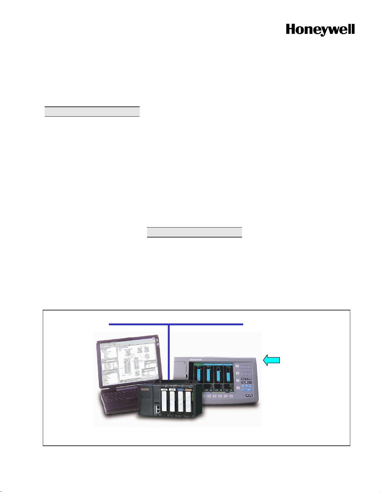
Ethernet
Hybrid
Control
Designer
Software
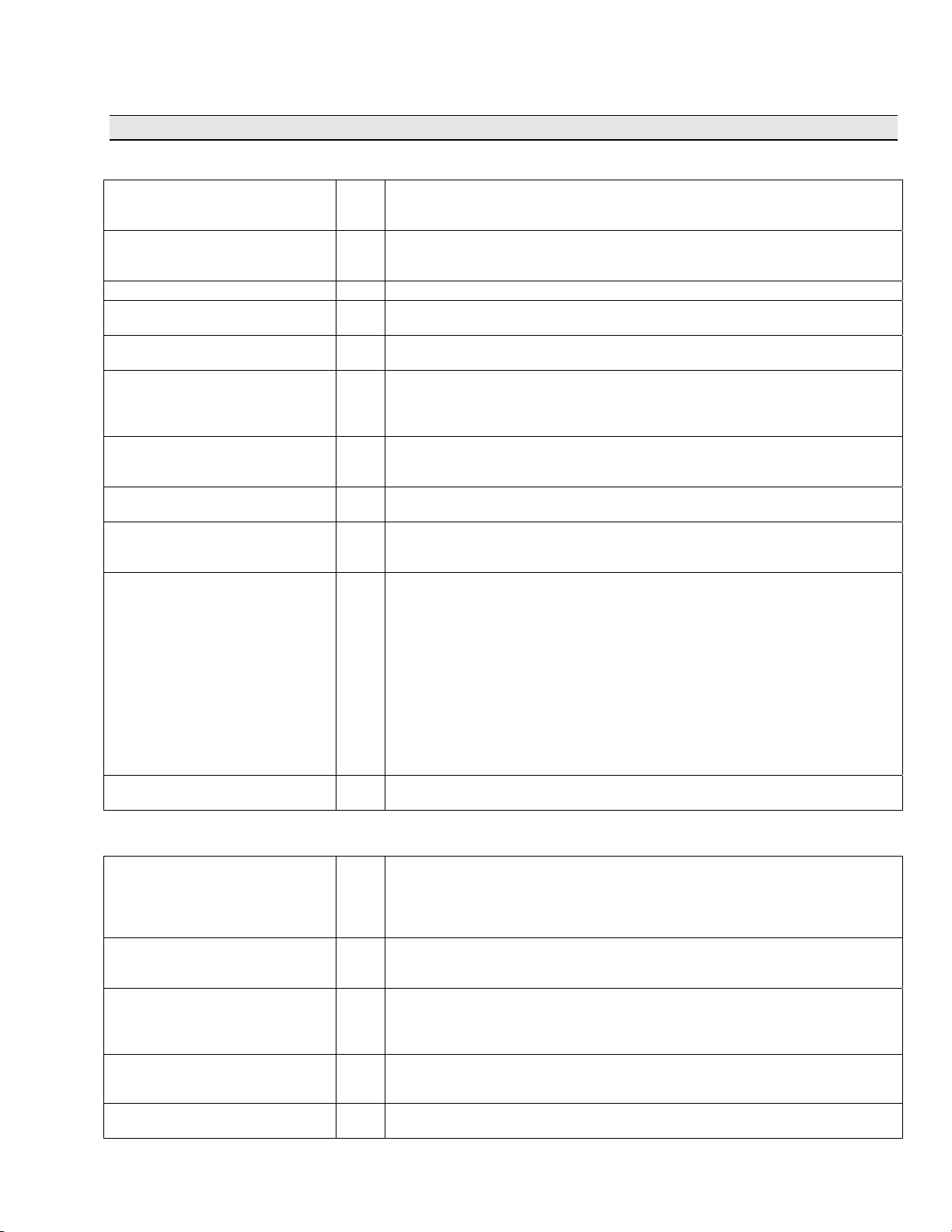
HC900 Hybrid Controller
1042 OI
Figure 1—HC900 Hybrid Controller Overview
· Furnaces
· Kilns
· Autoclaves
· Dryers
· Fermenters
· Water treatment
· Boilers
· Utility DAQ
· Pump stations
· Retorts
· Sterilizers
· Crystal Growing
· Extruders
· Pilot Operations
上海市水泉路88弄8号503室 电话:021-56356105 传真:021-56356109

51-52-03-31
Page 2
HC900 Controller
The rack based HC900 Controller is
available in 3 rack sizes with 4, 8 or 12
I/O slots each to support a wide range
of requirements.
C50 CPU —For greater installation
flexibility the C50 CPU allows up to 4
additional remote racks to be
connected to a single controller (with
its local I/O rack) to reduce wiring and
installation cost. A variety of analog
and digital I/O modules are available to
support a total of 960 I/O points,
including up to 256 analog input points
and 64 analog output points per
controller.
C30 CPU —The C30 CPU supports a
single rack with 4, 8 or 12 I/O slots and
can accommodate up to 96 analog
inputs or 192 total I/O points.
A standard Ethernet communication
port on the C50 and C30 CPUs
provides open connectivity to PCs or
other supervisory interfaces and
supports peer data exchanges to other
controllers.
Inputs and Outputs — A variety of I/O
modules are available for selection in
creating a custom control solution.
These include:
8 point universal analog input cards:
Inputs may be mixed on a card and
may include multiple thermocouple
types, RTDs, ohms, voltage or
millivoltage types – all easily
assigned using the Hybrid Control
Designer configuration tool. High
point to point isolation simplifies
installation and saves the expense of
external isolation hardware.
4 point isolated analog output card:
Supports from 0 to 20mA each.
16 point digital input cards: Contact
closure type, DC voltage and AC
voltage types.
8 point AC or 16 point DC digital
output cards
8 point relay output card: four form C
type and four form A
type relays.
Remote I/O- Up to 4 I/O racks may be
remotely mounted from the controller
via an Ethernet-private 10Base-T
connection at up to 300 meters (984
feet) between the controller and the
most remote rack using two Ethernet
hubs.
Insert & removal of I/O under power-
For ease of maintenance, the HC900
controller supports removing and
inserting I/O modules from the card
rack without removing power from
the
controller. Each card is sensed for
validity by the controller and auto-
configured on insertion.
Remote Terminal Panels — Optional
DIN rail mounted Remote Terminal
Panels (RTPs) are available for use
with pre-wired cables to reduce
installation time and labor expense.
Three types of RTPs are available:
analog inputs, relay outputs and other
I/O modules. Three cable lengths are
also available to match hardware to
installation variations. Analog input
RTPs include transmitter shunt
resistors and transmitter power
terminals with individual circuit fuses.
The RTP panels also switch field
power to allow module removal and
installation under controller power.
Function Blocks
Each HC900 Controller can support up
to 2000 analog or digital function
blocks. Each function block algorithm
may be used any number of times in a
control strategy unless specifically
identified with quantity limits. Of the
more than 100 function blocks
available, 12 block types have limits
imposed. These include:
C50
C30
Control Loops – 32 8
Setpoint Programmers – 8 8
Setpoint Schedulers – 2 2
Sequencers – 4 4
Alternators – 6 6
Stages – 8 8
Ramps – 8 8
Hand/Off/Auto – 16 16
Device (Pump) Control – 16 16
Pushbuttons (4 PB’s/block) – 8 8
Sel switches (4-position) – 8 8
Position Proportional Output – 64 16
User configurations are permanently
retained in flash memory in the
controller. In the event a PC
configuration file is lost or misplaced, it
can be easily reconstructed using the
upload function of the Hybrid Control
Designer configuration software or via
the 1042 and 559 OIs. Simply read the
configuration from the controller to
exactly
duplicate the original
configuration, including all text
descriptions and operator interface
display selections. In the event edits to
a controller’s configuration are required
after the unit is in operation, the on-line
download function of the HC900 Hybrid
Control Designer software allows
configuration changes while in the Run
mode, limiting process disturbances.
The dynamic control status is retained
in battery backed
RAM memory in the
controller. This function minimizes
process upsets during momentary
power interruptions and other
discontinuous operations.
Advanced control and
computational capability — A large
assortment of analog and digital
function blocks are available to solve
the most demanding control
requirements. Typical analog function
blocks include totalizers, free-form
math, average, mass flow, function
generator, periodic timers based on
real-time, carbon potential, RH, Dew
Point, signal selection
, comparison,
and many others. These blocks may
be configured to create control
schemes that precisely address the
needs of your process. Digital status
outputs are also provided on many of
the analog function blocks to facilitate
intelligent signal alarming and default
operation strategies. Typical logic
function blocks include AND, OR,
XOR, NOT, Latch, Flip-flop, On/Off
Delay and Resetable timers, Counters,
Free-form Boolean logic and more.
The execution of analog and digital
functions is seamlessly integrated into
a single control strategy in the
controller.
I/O Capacity
Input Type Point per Module Max. Points per C50/C30 Controller
Analog In 8 256/96
Analog Out 4 64/48
Digital In 16 960/192
Digital Out 8 AC or 16 DC 960/192
上海市水泉路88弄8号503室 电话:021-56356105 传真:021-56356109
51-52-03-31
Page 3
Loop Control- The robust control
loops of the HC900 Controller support
configurations from simple PID to
interactive cascade, ratio, duplex,
position proportioning and three
position step for motor positioning or
custom control strategies. Standard for
every control loop is auto-tuning using
Honeywell’s performance proven
Accutune II tuning algorithm. A
selectable «Fuzzy Logic» algorithm is
also provided for each loop to suppress
unwanted process setpoint overshoot.
A soft start feature allows output rate
limiting for protection of a process load
on startup or after power failure.
Logic — Logic programming may be
used to implement more robust and
higher speed logic functions in the
controller. The fast scan program
executes all inputs, outputs and
function blocks as fast as 27
milliseconds. The fast scan instruction
set includes 2, 4 and 8 input logic
blocks with selectable input inversion
plus timers, triggers, latches, counters,
timers, math and other supporting
functions. A Sequencer function is also
included with functionality beyond
typical drum sequencers.
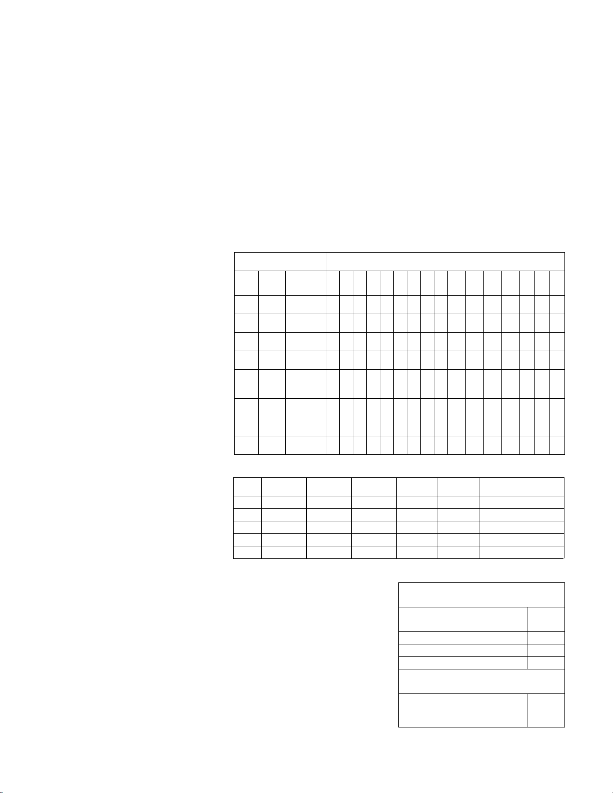
Sequence Control
Outputs
Step
State State
Name
1 2 3 4 5 6 7 8 9 10 11 12 13 14 15 16
1 1 PURGE 1 0 0 1 0 1 0 0 0 1 1 0 1 0 1 1
2 5 AGITATE 1 0 1 0 1 0 1 0 0 1 1 0 1 0 1 1
3 2 FEED B 0 1 1 1 1 0 1 0 0 1 1 0 1 0 1 1
4 3 MIX 1 1 1 1 1 1 1 1 1 1 1 0 1 0 1 1
5 8 PREHEAT 0 0 0 1 0 0 1 0 0 1 1 0 1 0 1 1
↓
Sequencers — The HC900 controller
supports up to four sequencer function
blocks, greatly enhancing configuration
of sequence operations. Each
sequencer supports up to 16 digital
outputs that may be either on or off in
each of 50 states e.g. PURGE, FILL,
HEAT, etc. The sequencer may have
up to 64 sequential steps that activate
within the states of the process. Steps
of the sequencer may be configured to
advance based on time, on event (2
per step), or a manual advance. A
separate jog function is also provided.
The function can also configure an
analog output on a step basis. The
operational sequence for the steps is
retained in a separate sequence file in
the memory of the controller that
may
be selected on-demand through a user
interface or via a recipe. Up to 20
sequences may be stored.
64 50 STOP 0 0 0 0 0 0 0 0 0 0 0 0 0 0 0 1
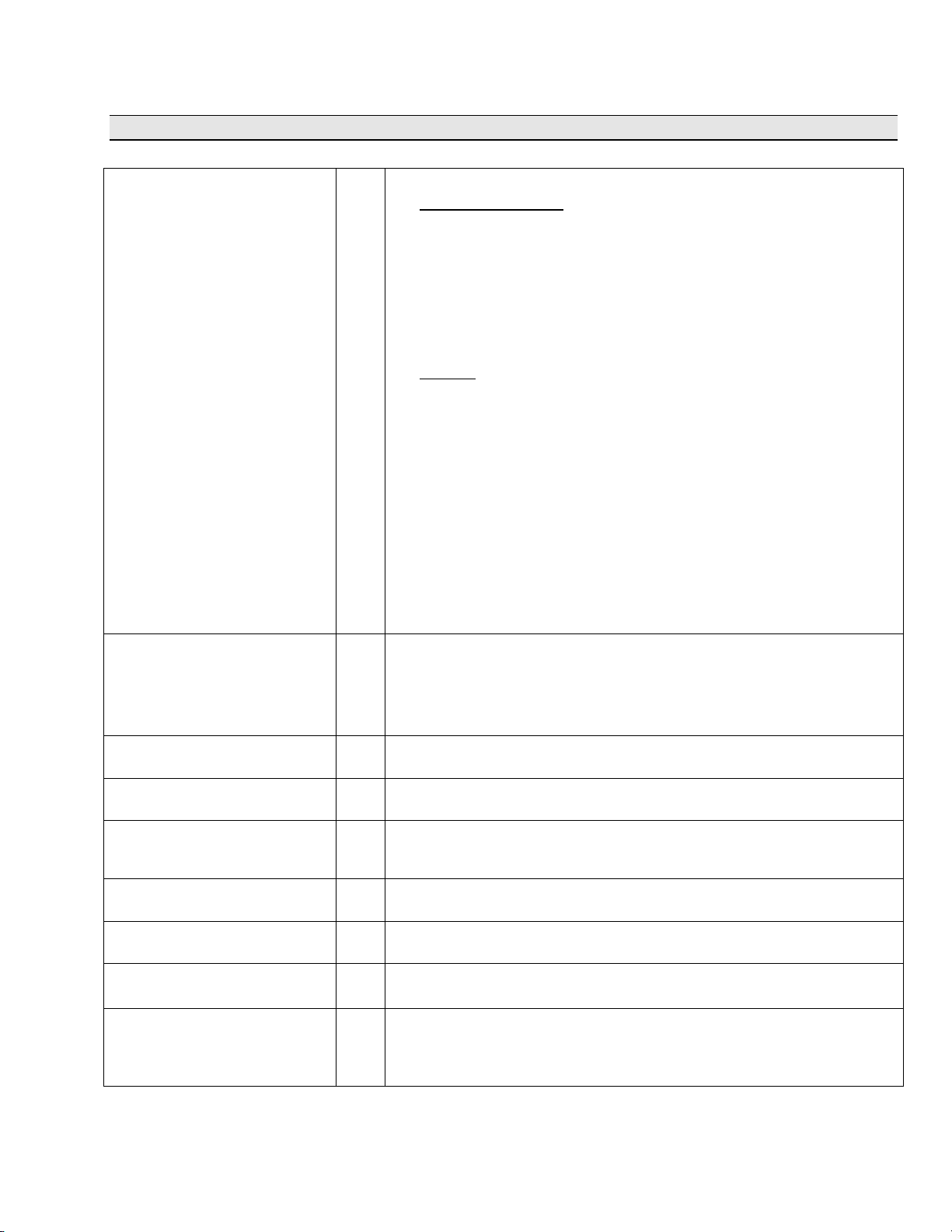
Setpoint Profile Table
Seg Ramp/
Soak
SP
Value
Time/
Rate
Aux
Out
Guar
Hold
Events
1 Ramp 100 20 0.0 OFF 100110000000000
2 Ramp 500 30 1.1 OFF 100100100000000
3 Soak 1300 90 1.1 ON 101110100000000
4 Ramp 1300 50 1.1 OFF 100100100000000
5 Soak 100 0.1 0.0 OFF 00000000100000
Set Point Programming — Up to 8
independent set point programmers,
each with an auxiliary soak output may
be configured. A pool of up to 99
profiles, each with up to 50 segments
may be stored in controller memory for
user selection. Each programmer may
have up to 16 event outputs for
integration with the sequence control
functions. Features such as
guaranteed soak, jog to a segment and
looping are also provided.
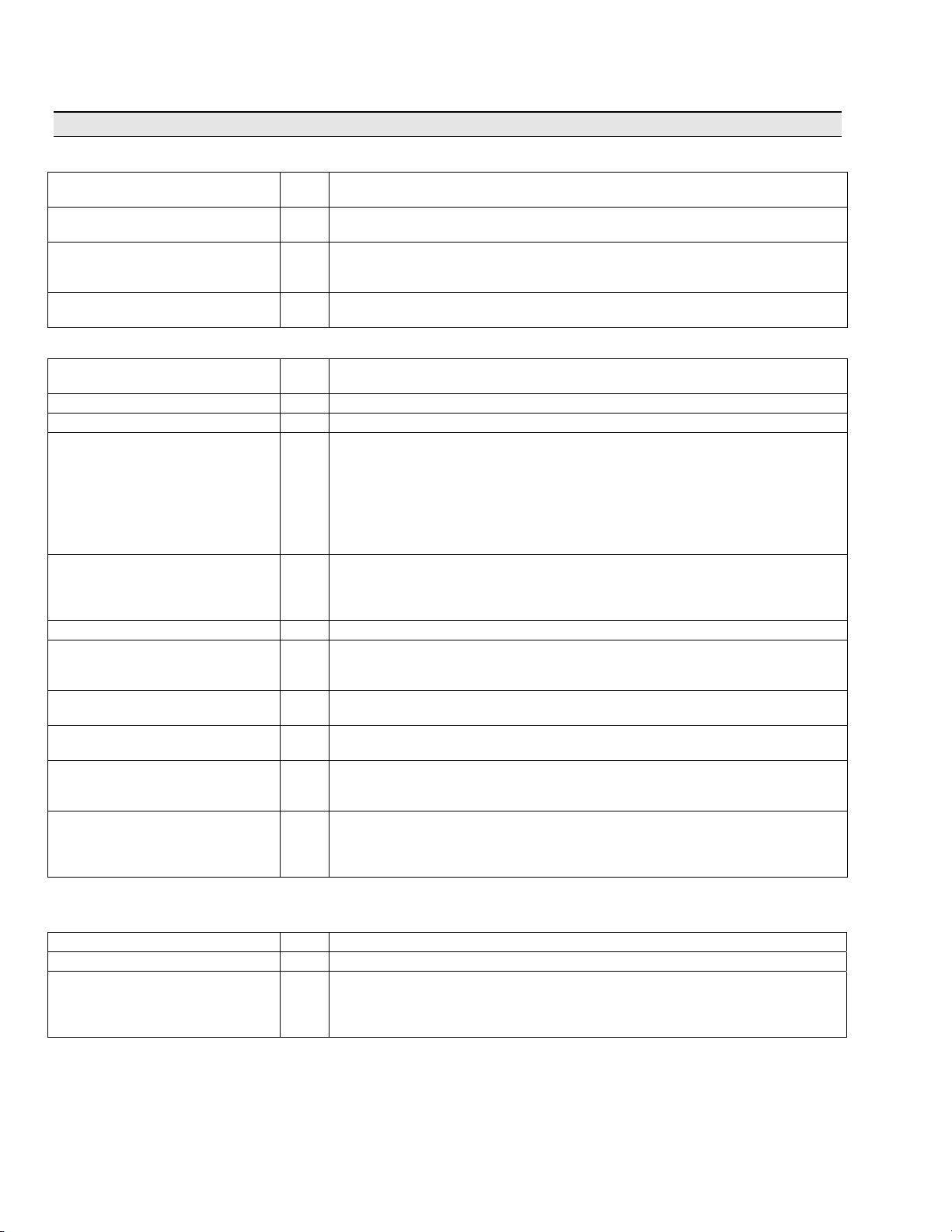
Recipe: P1023-F7
TYPE 1023 HARDEN
Variable
Tag Descriptor
Value
PROFNUM Profile Number 2
BIAS2 TempBias–Zone2 12
BIAS3 TempBias–Zone3 18
Up to 50 Variables
↓
Setpoint Scheduling — Up to 2
independent setpoint scheduler
functions may be configured. The
scheduler function provides up to 8
ramp and soak outputs plus up to 8
soak only outputs that operate on a
common time base. The scheduler
also supports up to 16 event digital
outputs. Soak guarantee, jog to a
segment and nested looping features
are also provided. Applications include
multi-zone diffusion furnaces, CVD
furnaces, and environmental
chambers. Up to 20 schedules can be
stored in the controller for user
selection.
Recipes – Up to 50 recipes are stored
in the controller. Recipes consist of up
to 50 analog and digital Variables
assigned within the configuration. This
allows Variables representing setpoint
profile, setpoint schedule, or sequencer
numbers and/or other Variables for
associated loop setpoints, bias values,
alarm setpoints, limits, setpoints to
external controllers, digital states,
tuning constants, etc. to be part of a
recipe. Recipes are selected by recipe
tag name and descriptor from the
HC900 Operator Interface or via a
Recipe Selection block with a recipe #
input.
HIALMSP1 F1 Hi Temp Alarm 1280
上海市水泉路88弄8号503室 电话:021-56356105 传真:021-56356109

51-52-03-31
Page 4
HC900 Function Block Types
I/OBlocks (F=Fast Scan Rate, N=Normal Rate)
Analog Input N
Universal Analog Input, with table selection of input type (See Table 3 )
Filter – 1
st
order lag, 0 to 120 seconds
Bias – Input value adjust for calibration correction
Burnout – Off, Upscale, Downscale, Default Value
Warn Output – activates if thermocouple resistance > 100 ohms.
Input Disable –digital input when ON disables input, sets output to a defined
default
Analog Output N
Regulated analog output current
Input scaling in Engineering Units, Output scaling within 0 and 20 mA
Slew rate definable, Fail output pin is ON when output fail sensed, Failsafe
definable
Digital Input (1) F,N
Provides the digital status of a digital input point. The output status may be
inverted. Both fast logic (27 ms) and normal logic (500ms analog rate) blocks
available. Fail Output – activates on failed input channel or failed remote rack
communications.
Digital Input (Up to 8 inputs) F,N
Provides the digital status of the first or last 8 digital inputs of a 16 point input
card. The output status may be inverted. Both fast logic (27 ms) and normal logic
(500ms analog rate) blocks available. Fail Output – activates on failed input
channel or failed remote rack communications
Digital Output (1) F,N
Directs a digital status to a physical logic output. Output status may be inverted.
Both fast logic (27 ms) and normal logic (500ms sec analog rate) blocks
available. Fail Output – activates on output failure or failed remote rack
communications.
Digital Output (Up to 8 outputs) F,N
Directs 8 digital statuses to 8 physical logic outputs of an 8 point output card or
to the first or last 8 physical logic outputs of a 16 point output card. Output status
may be inverted. Both fast logic (27 ms) and normal logic (500ms analog rate)
blocks available. Fail Output – activates on any one of 8 outputs with failed
output or failed remote rack communications.
Time Proportioning Output
(applied to any PID output)
N
Proportions the amount ON time and OFF time of a digital output.
Input scaling in engineering units
Cycle time—2 second to 120 seconds
Output minimum ON and OFF time—0 seconds to 15 seconds
Position Proportional Output
C50 CPU up to 64 per controller
C30 CPU up to 16 per controller
N
A combination Input and Output function block that includes feedback input
configuration and increase/decrease digital output configuration.
Positions actuators with slidewire, current or voltage position feedback sensors.
Provides outputs for actuator position (0 to 100%), motor fail, and feedback fail –
automatically defaults to 3-position step on feedback fail.
Input scaling in engineering units
Actuator speeds from 12 to 300 seconds
Output limits – adjustable (between 0 and 100%)
Deadband – adjustable (0.5 to 5%)
Feedback filter – adjustable (0 to 3 sec.)
Feedback input types:
Slidewire 100 to 250 ohms ( requires AI card 900A01-0002)
Slidewire 250 to 1000 ohms (requires AI card 900A01-0002)
mA — 4 to 20mA
mA — 0 to 20mA
Voltage — 0 to 1V
Voltage — 0 to 5V
Feedback calibration – HC Designer, 1042 or 559 Operator Interfaces
Automatic, Semi-automatic, and Hand methods supported.
上海市水泉路88弄8号503室 电话:021-56356105 传真:021-56356109
51-52-03-31
Page 5
HC900 Function Block Types (continued)
Control Loop Function Blocks (F=Fast Scan Rate, N=Normal Rate)
PID
C50 CPU — up to 32 per controller
C30 CPU – up to 8 per controller
N
PID algorithm includes:
• Accutune II auto-tuning
and selectable fuzzy logic overshoot suppression
• PID A (normal) or PID B (only integral response to SP change) operation,
DUPA and DUPB operation which switches tuning constants for heat/cool
applications
• Two sets of PID constants selectable via program control. Choice of Gain or
Proportional Band entry and Integral time or Repeats/minute entry
• Setpoints—Two setpoint values or one value and one remote setpoint
• Setpoint tracking – Local SP tracks PV or RSP on a RSP to LSP change
• Setpoint limits, output limits, SP rate of change
• Soft start
for output rate limiting on startup or after power fail (not available
with output tracking)
• Ratio and Local/Remote Bias selections for Ratio control applications
• Feedforward input (scaled in % of output)
• Back calculation output for Cascade operation (supplied to primary loop)
• Output tracking to track a remote input (for backup applications)
• Remote A/M, R/L mode switching and mode status outputs
• Function block access to tuning constants for gain scheduling
• Alarms—Two outputs with up to two high, low, or dev band conditions each
Inputs: PV, remote setpoint, feedforward, output track and track command, ratio,
bias, switch block connection, mode switch block connection, and back
calculations
Outputs: Control output, working setpoint, alarm status (2), Autotune indication,
mode status
PID for Carbon Potential
C50 CPU — up to 32 per controller
C30 CPU – up to 8 per controller
(displaces PID)
N
A combined carbon potential calculation and PID algorithm for controlling the
carbon potential of furnace atmospheres using a zirconia probe input and
temperature input. Local/remote %CO adjustment, probe manufacturer selection
(4 selections), anti-sooting protection, dewpoint calculation output, and furnace
factor adjustment is supported; probe burn-off configurable.
PID with 3 Position Step Output N Motor position control without position sensing. Standard PID features with
addition of hysteresis (in %) and full stroke time (in sec.) entries for motor.
ON/OFF Control (32 standard)
(displaces PID)
N ON/OFF control algorithm with selectable hysteresis
Loop Switch Inputs N Digital interface to control loops to initiate autotuning, change control action,
force bumpless transfer, select tuning set #1 and select tuning set #2. Connects
to PID (all) and ON/OFF block switch input.
Loop Mode Selection N Digital interface to control loops to select automatic or manual modes and/or
local or remote setpoint. Connects to all control loop types.
Mode Decoder (Mode Flags) N Decodes control loop mode status into a set of discrete (Boolean or digital) mode
flags.
Write Tuning Constants N
Automatically changes the GAIN, RATE, and RESET parameters of an internal
PID loop without operator interaction. A digital input controls changes.
Auto-Manual Bias (32 standard,
displaces PID) (for Boiler Control
applications)
N
Allows a manually adjusted output to be maintained on transfer to automatic by
applying bias to the input signal (from a Steam master to adjust participation of
boiler). Bias value is maintained as output value tracks input value changes.
Consumes 1 loop.
上海市水泉路88弄8号503室 电话:021-56356105 传真:021-56356109

51-52-03-31
Page 6
HC900 Function Block Types (continued)
Setpoint Programmer and Recipe Function Blocks (F=Fast Scan Rate, N=Normal Rate)
Setpoint Programmer (8
maximum)
N Produces a setpoint output for a time-based ramp/soak profile that is loaded into
the block. (See Setpoint Programming description for profile details.)
Inputs:
Process Variables, up to 3, to establish setpoint guarantee operation based on
a deviation band from setpoint. Profile Number (for autoload of a profile # for
next run), New Starting Segment (uses a Set input to enter a new segment
number).
Digital Inputs:
Enable (allows programmer to be operated), Set (to load a program or new
start segment), Start, Hold, Restart (from power failure, can allow slower ramp
up to previous SP to protect product), Reset, Advance, Jog (to a specified
segment), and Guarantee Hold (to synchronize with another programmer).
Outputs:
Setpoint value, segment number, program number, time remaining in segment,
time elapsed in segment, program elapsed time.
Digital Outputs:
Status (Ready, Running, Hold, Stopped), synchronize hold state, program
state
Setpoint Program Events (up to 16
events per block)
N Provides up to 16 digital status outputs that may be ON or OFF on a per
segment basis. Inputs include program number, segment number, and program
state (READY, RUN, HOLD, GHOLD, or STOP) from setpoint program block
from program state output.
Setpoint Program Synchronizer N Used to synchronize the operation of two setpoint programs given the Run, Hold
and Reset signals from each program.
Recipe Block F,N Used to initiate loading of recipe values into a chosen set of controller variables
based on a recipe number. Inputs include recipe number and load command,
allowing remote recipe selection.
Setpoint Scheduler Function Blocks (F=Fast Scan Rate, N=Normal Rate)
Setpoint Scheduler (2 maximum)
N Produces up to 8 ramp or soak setpoint outputs on a common single time base.
(See Scheduler description for details.)
Inputs:
Process variables, up to 8, to establish setpoint guarantee operation based on
deviation from setpoint. Schedule number is used for automatic schedule
loading and starting segment number allows first segment selection.
Digital inputs:
Dedicated input for connection to State Switch block output.
Outputs:
Up to 8 setpoint values, segment number, schedule number, time remaining in
segment, time elapsed in segment, schedule elapsed time.
Digital Outputs:
Dedicated output for connection to State Flags block input.
State Switch Block N Provides digital switch status inputs to the Scheduler block for Run, Hold, Reset,
Ghold, Advance and Jog.
State Flags Block N Accepts status output from the Scheduler block and provides digital output
signals for Run, Hold, Ghold, Ready and Stop.
Setpoint Scheduler Auxiliary
Output Block
N Provides up to 8 additional analog setpoint (soak only) values for each segment
of the schedule.
Inputs: Up to 8 process variables used for display.
Event Decoder N Provides up to 16 digital outputs that may be ON or OFF on a per segment
basis.
上海市水泉路88弄8号503室 电话:021-56356105 传真:021-56356109

51-52-03-31
Page 7
HC900 Function Block Types (continued)
Auxiliary Control Function Blocks
(F=Fast Scan Rate, N=Normal Rate)
Lead Lag Signal Conditioner N Modifies an analog input value to include lead and lag time constants when a
digital input is true.
Lead time constant = 0 minutes to 99 minutes
Lag time constant = 0 minutes to 99 minutes
Function Generator N Generates an output characteristic curve based on up to 11 configurable
“breakpoints” for input and output values.
High/Low Limiter F,N Limits an analog variable between high and low limit values. Provides separate
digital status outputs when high or low limit values are exceeded.
Rate (Velocity) Limiter N Limits the rate at which an analog variable can change when a logic input is ON.
Provides independent increasing and decreasing rate of change limit values.
Separate digital status outputs indicate when high or low rate limits are active.
Rate of Change N Provides an output value representing the rate of change value of the input in
units per minute. Output value is positive for increasing input values and
negative for decreasing input values. Two setpoint values and digital outputs are
provided to indicate excess increasing or decreasing rates of change or
insufficient increasing or decreasing rates of change.
Read Constant F,N Provides a read access to internal static parameters of selected blocks by Block
number and parameter index number.
Write Constant F,N Provides write access to internal static parameters of selected blocks by Block
number and parameter index number.
Write Variable F,N Provides a write of a value to a selected analog or digital Variable number based
on the ON state of a digital input.
Track and Hold N Allows updating or holding the value of an analog input based on the state of a
digital input.
BCD Translator F,N Accepts up to 8 digital inputs in sequence and interprets the ON/OFF status of
the first 4 inputs as a BCD value between 0 and 9, and the second 4 digits as a
value between 10 and 90.
Digital Encoder N A 16 input block whose output is the decimal value of the number of ON inputs.
Specific Application Principal Blocks (F=Fast Scan Rate, N=Normal Rate)
Device Control (16 maximum)
(for Pump Control)
N Provides device control (pumps, etc) including Start, Stop, Feedback Delay times
along with feedback confirmation and failure check.
Stage (8 maximum) N Accepts one or two analog variables and compares the values to high and low
setpoints for each of 4 stages per block. Outputs are digital signals that remain
ON after exceeding one setpoint until exceeding the second setpoint value for
the specific stage.
Ramp (8 Maximum) N Accepts an analog variable and re-scales the value to new, user specified units.
Up to 4 re-scale calculations may be configured per block. The re-scale
calculation that is currently active is controlled by digital inputs to the block.
Digital inputs may also be used to force the output to a high or low limit value.
Alternator (6 maximum) N The alternator accepts up to 16 digital inputs and, on a one for one basis, turns
on up to 16 digital outputs as determined by a user specified alternating
sequence. Alternator sequences include:
Direct – Inputs are mapped to specific outputs.
Rotary – Outputs are managed on a Last ON/ First Off (LOFO) basis and the
mapped sequence indexes by one each time all of the outputs are off.
FOFO – First On, First Off alternates the outputs based on the sequence in
which the outputs were turned on. The first output to turn on is moved to the end
of the list once it turns off.
Fixed – The output sequence follows a user specified mapping sequence. A
manual advance causes the mapping sequence to index by one when enabled.
Both “make-before –break” and “break -before –make” selections are available
for the block with user specified time delays for output changes.
上海市水泉路88弄8号503室 电话:021-56356105 传真:021-56356109
51-52-03-31
Page 8
HC900 Function Block Types (continued)
Signal Selector Function Blocks (F=Fast Scan Rate, N=Normal Rate)
High Selector/Low Selector F,N Provides the highest (high select) or lowest (low select) of two analog input
variables.
Switch N Output switches between two analog input values based on the status of a digital
input.
Bumpless Analog Transfer N Output switches between two analog input values based on the status of a digital
input. When switched, output ramps to the new value at a specified rate. A rate
value is available for each direction.
Rotary Switch N Single output is selected from up to 8 analog values based on the numerical
value of a select input (1 to 8).
Calculation Function Blocks (F=Fast Scan Rate, N=Normal Rate)
Compare F,N Compares one analog variable to a second analog variable and generates
separate digital outputs to indicate greater than, equal, or less than status.
Absolute Value F,N Provides an absolute value output for a single analog variable input.
Square Root N Output is the square root of a single analog variable input.
Mass Flow N Calculates the mass flow of gases when measuring flow using an orifice plate.
Output = Kg * sqrt((Kx * X + Bx) (Ky * Y + By)/(Kz * Z + Bz))
with inputs X = differential pressure
Y = pressure, and
Z = temperature.
A low flow cut-off feature provides a user-specified drop-off value below which
the output goes to zero.
Minimum – Maximum – Average –
Sum
N Accepts inputs from up to 6 analog variables and outputs analog variables
representing the highest value, lowest value, average value, sum, and standard
deviation. Removes bad inputs and provides an alarm output for deviations of
any variable outside user-specified standard deviation.
Negate F,N Accepts a single analog variable input and negates the output.
Totalize N Integrates an analog variable using a specified rate. Rate may be in units per
minute, hour, or day. A preset is provided to indicate when a specific quantity
has been accumulated. Separate enable and reset inputs are provided.
Deviation Compare N Compares up to 6 analog variables to deviation limits set around a 7th variable. If
any variable is outside the limits, a digital signal is provided.
Relative Humidity N Calculates the relative humidity using wet bulb, dry bulb, and atmospheric
pressure inputs. Output may be in degrees Fahrenheit or Celsius.
Dewpoint (12 maximum) N A dewpoint PV is supplied to a PID function block for dewpoint control. Used in
conjunction with other blocks including a PID to generate more elaborate control
strategies than that provided by the carbon potential function block.
Continuous Average N Provides the average value of a single analog parameter for a user-specified
time period, plus the running average within the time period. Average value is
updated at the end of each sample period. Time periods to 1440.0 minutes are
supported. A hold input allows excluding samples from the average when active.
Math Function Blocks
(F=Fast Scan Rate, N=Normal Rate)
Scale and Bias F,N Output = (K * X) + b with single analog variable input X.
Two and Four Input Math F,N Executes +, – or * on two or four analog variable inputs, / on two inputs.
Free Form Math N Calculates the result of a user-specified equation with double precision. The
block accepts up to 8 input signals (including Constants or Variables). Operators
include: +, -, , /, ^, and multiple levels of parentheses. Functions include:
absolute value, exp, ln, Log, neg, sqrt. Example: a*(sqrt(b+c))+d
上海市水泉路88弄8号503室 电话:021-56356105 传真:021-56356109
51-52-03-31
Page 9
HC900 Function Block Types (continued)
Logic Function Blocks (F=Fast Logic Rate, N=Normal Rate)
AND, OR, XOR (2 inputs)
Boolean logic blocks
F,N Provides a digital status output based on the digital status of two digital inputs for
logic AND, OR, or XOR (exclusive OR) operations. Input status of each input
may be inverted.
AND, OR (4 and 8 inputs)
Boolean logic blocks
F,N Provides a digital status output based on the digital status of four or eight digital
inputs for logic AND or OR operations. Input status of each input may be
inverted.
NOT (Complement) F,N Inverts a logic input status.
Latch F,N Provides a digital output that turns ON when a digital input turns ON and remains
ON (latched) after the input goes OFF until an unlatch input turns ON.
Edge Detection Element
(One-shot) [Trigger]
F,N Provides an ON state of its output for one controller scan when a digital input
goes from OFF to ON.
Toggle (Flip-Flop) F,N Provides an ON state output when a digital input goes from OFF to ON and the
previous state of the output was OFF, and an OFF state output when the digital
input goes from OFF to ON and the previous state of the output was ON. A
reset input holds the output OFF when the digital input is ON or active high.
Free Form Logic F, N Reads eight digital inputs and calculates the output based on specified Boolean
logic functions (e.g., AND, OR, NOT, etc.) and multiple levels of parentheses.
Example: (A*B)+C
Pushbutton F, N Provides a one-shot output based on an OFF to ON change of an operator
interface key action. Supports four pushbuttons per block.
Four Selector Switch N Provides up to 16 digital outputs in groups of four outputs each. Only one output
from each group may be ON at a time and when selected automatically turns
other outputs OFF. Simulates 4-position panel selector switches.
Sequencer (4 maximum) (Fast
logic scan only)
F, N The sequencer function block controls the output statuses of up to 16 digital
outputs and one auxiliary analog output. Each combination of outputs
represents a “State” of the sequence such as Heat, Mix, or Cool, for example.
The function block supports up to 50 states.
The sequencer contains up to 64 steps. Each step enables a State, allowing for
a State to be designated for several steps.
Each State supports two digital events as inputs that can designate the end of
the associated step.
Time in seconds or minutes, a manual advance, or a digital event can be used to
terminate a sequencer step and cause the sequence to advance.
A pool of 20 sequences, up to 64 steps each, may be stored in controller
memory for quick recall and assignment to any of the 4 sequencers.
Hand/Off/Auto (16 maximum) N Provides Hand-Off-Automatic outputs based on digital inputs emulating a
standard H-O-A panel switch
Counters/Timers Function Blocks
(F=Fast Logic Rate, N=Normal Rate)
Resettable Timer F, N Provides a timing function based on an enable input. Elapsed time value is
provided as an output. A Preset value allows settings from 1 second to 999999
seconds. A digital output is ON when time value is equal to the preset. An
up/down digital input is provided to allow reverse timing from the preset value. A
pre-load value allows initiating the timer to a non-zero starting time.
Periodic Timer N Provides an ON state output for one controller scan cycle based on a specified
time period using the controller real-time clock. Periods may be monthly, weekly,
daily, or time period in a day.
Up/Down Counter F, N Counts the number of raising edge logic transitions on the input to the block up
to a preset value. When the preset value is reached a logic output is enabled. A
reset input resets the block. Value may be set to increase to the preset value or
decrease from the preset value (1–99999).
ON-Delay Timer F, N An OFF to ON change of the digital input is delayed on the block output by a
user-specified time (0.1 seconds to 999.9 seconds).
OFF-Delay Timer F, N An ON to OFF change of the digital input is delayed on the block output by a
user-specified time (0.1 seconds to 999.9 seconds).
上海市水泉路88弄8号503室 电话:021-56356105 传真:021-56356109
51-52-03-31
Page 10
HC900 Function Block Types (continued)
Alarm and Signal Monitoring Blocks (F=Fast Scan Rate, N=Normal Rate)
High Monitor F, N Accepts two analog values and provides a digital status output if the first input is
higher than the second input. A hysteresis adjustment is provided to prevent
output cycling.
Low Monitor F, N Accepts two analog values and provides a digital status output if the first input is
lower than the second input. A hysteresis adjustment is provided to prevent
output cycling.
Analog Alarm N The analog alarm block accepts an analog signal as a process variable and
compares it to a user-entered limit value (setpoint) to determine an alarm
condition. The setpoint may be entered by the user or be another analog signal
in the controller. Alarm actions may be high, low or high deviation, low deviation
or band deviation. For deviation alarming, a second analog signal provides the
reference and setpoints represent deviation from the reference. The alarm output
may be inverted to create normally active digital output. A user selection for
latching until acknowledged or automatically reset is provided. A user-specified
hysteresis value in the engineering units of the process variable is provided. An
on-delay time value up to 240 seconds is available to prevent momentary alarm
actions. A digital reset input is available to disable alarm actions.
System Monitor Block
(1 block for normal scan and 1
block for fast logic scan) – (do not
count against the maximum block
count)
F, N Provides system and start-up status outputs including:
• Program scan cycle time
• Newstart pulse (ON for one scan cycle after a “cold” start (reset))
• Restart pulse (to activate a custom control action on power-up after power
loss)
• Two common alarm outputs — Active Unacknowledged (ON when at least one
alarm not ack’d), Active alarm (ON when at least one alarm is active), for
assignment to digital outputs
• Time off (the time that power has been off previous to restart)
• Low Battery (alert to change battery without power shutdown)
• Hardware OK (ON when all hardware including remote racks are OK)
• Hi Temp (Cold Junction temperature exceeds limits on a rack)
• Bad Block
• Master Fail
• Locked (controller toggle switch is in Run/Locked or Program position)
• DS Limit (OI data storage has reached its alarm limit)
Alarm, Signal, and System Monitoring Blocks (continued) (F=Fast Scan Rate, N=Normal Rate)
IO Rack Monitor– (do not count
against the maximum block count)
N One monitor block per rack, 5 racks maximum (C50 CPU). Provides I/O module
fault status
Alarm Group (Up to 20 blocks) –
(do not count against the
maximum block count)
N Supports acknowledgement of a group of up to 12 alarms using a controller
digital signal to block, internal or external (for remote acknowledge). Each alarm
group consists of up to 12 alarms. Outputs include Unacknowledged alarm and
Active alarm states. The 20 blocks support up to 240 alarms.
Communications Blocks (Peer to Peer) (F=Fast Scan Rate, N=Normal Rate)
PDE (Peer Data Exchange)
Control
N Interfaces to one HC900 peer device, accessed by controller name, supporting 8
parameter read requests and 4 event-triggered writes. Outputs may be given tag
names for use in configuration strategy. Update rate can be configured from 500
ms to 5 sec.
PDE Read N Expands Read access for designated HC900 peer to an additional 16
parameters.
PDE Write N Expands Writes to designated HC900 peer by an additional 8 parameters, each
triggered on event.
上海市水泉路88弄8号503室 电话:021-56356105 传真:021-56356109
51-52-03-31
Page 11
HC900 Function Block Types (continued)
Other Diagram Items (F=Fast Scan Rate, N=Normal Rate)
Analog Variable F, N Connects to a function block’s inputs and can be changed from the operator
interface or via serial communications addressing.
Digital Variable F, N Connects to a function block’s inputs and can be changed from the operator
interface or via serial communications addressing.
T (Text) F, N Allows descriptive data to annotate a specific area of a function block diagram to
be entered. Four font sizes, four colors, bold/italics/underline supported. Text
may be entered multi-line.
Soft Wire F, N For reference only. Soft-wiring method is to double click on a block pin and then
clicks on a destination pin to complete soft-wire (or click to change direction en
route to destination pin).
Connector F, N Connects tagged signals to function block inputs.
Signal Tag F, N Allows a name to be assigned to a wire and accessed by the operator interface
or via serial communications.
Numeric Constant F, N A user-specified constant value that can be connected to function block inputs.
上海市水泉路88弄8号503室 电话:021-56356105 传真:021-56356109
 Loading…
Назначение
Гибридный контроллер Honeywell ControlEdge™ HC900
– это уникальный
контроллер, относящийся к семейству так называемых DCS
(Distributed Control System, Распределенная Система Управления) контроллеров. На
практике это
означает, что время
выполнения программы строго детерминировано.
Также
благодаря заложенным в контроллер техническим решениям
достигается возможность изменения программной и аппаратной конфигурации контроллера в
«горячем»
режиме без каких-либо
ограничений даже в нерезервированной конфигурации.
Эти свойства, наряду с возможностью полного резервирования системы позволяют
использовать ControlEdge™ HC900 для
автоматизации непрерывных процессов, работающих в режиме «24/7/365», где применение
традиционных ПЛК либо недопустимо, либо накладывает
большие ограничения на процесс внедрения программного
обеспечения.
Начиная с 2014 года контроллер ControlEdge™ HC900 также доступен в
версии Safety с поддержкой уровня функциональной безопасности по уровню SIL2. Общая
компонентная
база с контроллером >ControlEdge™ HC900 Process и ControlEdge™ PLC
делает построение
систем ПАЗ+РСУ эффективной как никогда.
Модуль универсального В/В с поддержкой SOE (Sequence of
Events, последовательность событий), позволяет упростить
проектирование и внедрение проектов и сократить количество ЗИП на складе заказчика.
Дополнительные материалы
Документы для скачивания:
![]() Loading…
Loading…
Назначение
Гибридный контроллер Honeywell ControlEdge™ HC900
– это уникальный
контроллер, относящийся к семейству так называемых DCS
(Distributed Control System, Распределенная Система Управления) контроллеров. На
практике это
означает, что время
выполнения программы строго детерминировано.
Также
благодаря заложенным в контроллер техническим решениям
достигается возможность изменения программной и аппаратной конфигурации контроллера в
«горячем»
режиме без каких-либо
ограничений даже в нерезервированной конфигурации.
Эти свойства, наряду с возможностью полного резервирования системы позволяют
использовать ControlEdge™ HC900 для
автоматизации непрерывных процессов, работающих в режиме «24/7/365», где применение
традиционных ПЛК либо недопустимо, либо накладывает
большие ограничения на процесс внедрения программного
обеспечения.
Начиная с 2014 года контроллер ControlEdge™ HC900 также доступен в
версии Safety с поддержкой уровня функциональной безопасности по уровню SIL2. Общая
компонентная
база с контроллером >ControlEdge™ HC900 Process и ControlEdge™ PLC
делает построение
систем ПАЗ+РСУ эффективной как никогда.
Модуль универсального В/В с поддержкой SOE (Sequence of
Events, последовательность событий), позволяет упростить
проектирование и внедрение проектов и сократить количество ЗИП на складе заказчика.
Дополнительные материалы
Документы для скачивания:
![]() Информационный лист ControlEdge™ HC900
Информационный лист ControlEdge™ HC900
![]() Брошюра ControlEdge™ HC900
Брошюра ControlEdge™ HC900
![]() Брошюра ControlEdge™ HC900
Брошюра ControlEdge™ HC900
![]() Каталог ControlEdge™ HC900
Каталог ControlEdge™ HC900
![]() Спецификация контроллера ControlEdge™ HC900
Спецификация контроллера ControlEdge™ HC900
![]() Спецификация контроллера ControlEdge™ HC900
Спецификация контроллера ControlEdge™ HC900
![]() Спецификация модулей ControlEdge™ HC900
Спецификация модулей ControlEdge™ HC900
![]() Спецификация среды выполнения ControlEdge™ HC900
Спецификация среды выполнения ControlEdge™ HC900
![]() Спецификация среды выполнения ControlEdge™ HC900
Спецификация среды выполнения ControlEdge™ HC900
![]() Спецификация программного обеспечения ControlEdge™ HC900
Спецификация программного обеспечения ControlEdge™ HC900
Преимущества
Линейка контроллеров ControlEdge™ HC900 представлена четырьмя моделями контроллера
Process (С30, С50,
С70, С75) и четырьмя моделями контроллера Safety SIL2 (С30S, С50S, С70S,
С75S)
Контроллер обладает следующими характеристиками:
- Общая компонентная база с контроллером ControlEdge™ PLC
- До 12-ти шасси ввода-вывода (до 4608 дискретных каналов
ввода-вывода) - Полное резервирование всех компонентов (модель С75/C75S)
- Никаких ограничений на изменение и загрузку прикладного программного
обеспечения (стратегий управления) в «горячем» режиме - Добавление/удаление модулей ввода-вывода в «горячем» режиме
- Замена всех компонентов в «горячем» режиме
- Быстрый цикл опроса — 10 мс для цифровых и аналоговых каналов модуля
унверсального
ввода-вывода UIO (900U02-xxxx), 100 мс для других (обновление каналов AI низкого уровня — 500
мс.) - Поддержка последовательности событий (SOE)
- Универсальный 16-ти канальный модуль ввода-вывода UIO (AI, AO, DI, DO) с поддержкой
уровня функциональной безопасности SIL2 - Один и тот же контроллер для РСУ и ПАЗ (Сертификат SIL2)
- Детерминированное время выполнения стратегий управления
- Непревзойденная простота в работе и конфигурировании
- Удобная автонастройка ПИД регуляторов
- Алгоритмы: ШИМ, позиционно-пропорциональное с обратной связью, трехпозиционное и т.д.
- Возможность хранения истории и событий в памяти контроллера
- Возможность отправки email по событиям
Архитектура системы
< Назад
Вверх
Гибридный контроллер Honeywell ControlEdge™ HC900 — это усовершенствованный
контроллер,
предлагающий модульную конструкцию, размер которой соответствует требованиям контроля и управления
данными широкого спектра технологического оборудования.
В сочетании с опциональным операторским
интерфейсом 900 Control Station, который тесно интегрирован с базой данных
контроллера, время
конфигурирования и настройки сводится к минимуму. Эта мощная комбинация вместе с проверенной
технологией
управления Honeywell обеспечивает пользователям идеальное решение для управления процессом.
Открытое
соединение Ethernet с протоколом Modbus TCP также обеспечивает доступ к сети с использованием
различных
программ HMI / SCADA.
Среда выполнения программы защищена с помощью независимого сторожевого таймера.
Конфигурация сети ввода-вывода поддерживает две топологии — «звезда» и «кольцо».
Сеть ввода вывода поддерживает:
- до 144 модулей ввода / вывода (12 стоек х 12 модулей на стойку)
- до 4608 дискретных каналов (12 стоек x 12 модулей на стойку x 32 канала на модуль).
Контроллер ControlEdge™
HC900 может быть сконфигурирован как система без резервирования ЦПУ, источников
питания, сети
связи с шасси ввода-вывода и модулей ввода-вывода, так и с резервированием всех компонентов.
Система без резервирования компонентов ControlEdge™ HC900
Система без резервирования ЦПУ, источников питания и модулей ввода-вывода может состоять
из:
- 4-, 8-, 12-слотовых шасси контроллера/модулей ввода-вывода без резервированного
источника питания - Нерезервированного ЦПУ (модели C30/C30S, C50/C50S, C70/C70S)
- ЦПУ устанавливается в одно шасси с модулями ввода вывода
-
Подключение к ЦПУ (только модели C50/C50S, C70/C70S) дополнительных шасси ввода-вывода
осуществляется с
использованием
модуля
связи с одним портом Ethernet, устанавливаемого в шасси ввода-вывода, по топологии «звезда»
(без использования дополнительного оборудования для одного шасси расширения или с добавлением
Ethernet-коммутатора в сеть ввода-вывода при использовании более одного шасси расширения) - Дополнительно. Источники питания могут быть резервированы путем использования 8-, 12-слотовых
шасси контроллера/модулей ввода-вывода с резервированным
источником питания - Дополнительно. Сеть связи с «верхним» уровнем (ЧМИ) может резервирована путем использования
порта E2 ЦПУ (только модели C70/C70SS)
Система с резервированием компонентов ControlEdge™ HC900
Система с резервированием ЦПУ, источников питания и модулей ввода-вывода может состоять
из следующих компонентов:
- 8-, 12-слотовые шасси модулей ввода-вывода с резервированным
источником питания - Шасси резервированного ЦПУ для установки двух ЦПУ (только C75/C75S) и двух источников питания
- Резервированного ЦПУ (модели C75/C75S)
-
Подключение к (ЦПУ) дополнительных шасси ввода-вывода по резервированной сети осуществляется
с
использованием
модуля
связи с двумя портами Ethernet, устанавливаемого в шасси ввода-вывода, по топологии «звезда»
(без использования дополнительного оборудования для одного шасси расширения или с добавлением
Ethernet-коммутатора в сеть ввода-вывода при использовании более одного шасси расширения)
или «кольцо». - Сеть связи с «верхним» уровнем (ЧМИ) резервирована
- Резервирование модулей ввода-вывода — программное
Контроллеры Honeywell выполняют функцию обработки данных с датчиков и выработки управляющих команд для оборудования. Модель Honeywell HC900 разработана для осуществления небольшого количества промышленных процессов. Гибридное устройство от Ханивел имеет модульную конструкцию и легкое управление.
Контроллер Ханивел имеет модульную структуру шасси. Модель HC900 проста в сборке и установке расширений. Устройство Honeywell поддерживает параллельную обработку – микропроцессор в каждом модуле выполняет обработку сигнала отдельно.
На модуле состояния питания контроллера от Honeywell расположены два светодиода. Когда индикатор состояния одного или обоих источников питания горит – состояние соответствующего источника в норме. Когда индикатор не горит – источник питания выключен, либо напряжение находятся вне допустимых пределов.
| Модификация | Артикул |
|---|---|
| Контроллер C30 | 900C30-0360-00 |
| Контроллер C30 SIL | 900C30S-0360-00 |
| Контроллер C50 | 900C50-0360-00 |
| Контроллер C50 SIL | 900C50S-0360-00 |
| Контроллер C70 | 900C70-0360-00 |
| Контроллер C70 SIL | 900C70S-0360-00 |
| Резервируемый контроллер C75 | 900C75-0360-00 |
| Резервируемый контроллер C75 SIL | 900C75S-0360-00 |
| Модуль аналоговых входов (8 каналов) | 900A01-0202 |
| Модуль аналоговых входов высокого уровня (16 каналов) -500mS | 900A16-0101 |
| Модуль аналоговых входов высокого уровня (16 каналов) -100mS | 900A16-0103 |
| Модуль аналоговых выходов, 0 — 20mA, (4 каналов) | 900B01-0301 |
| Модуль аналоговых выходов 0 — 20mA (8 каналов, 5 modules/rack) | 900B08-0202 |
| Модуль аналоговых выходов 0 — 20mA (16 каналов, 2 modules per rack) | 900B16-0202 |
| Модуль дискретных входов, Contact type, (16 каналов) | 900G01-0202 |
| Модуль дискретных входов, 24VDC (16 каналов) | 900G02-0202 |
| Модуль дискретных входов, 120/240 VAC, (16 каналов) | 900G03-0202 |
| Модуль дискретных входов, 120/240 VAC-125VDC, (16 каналов Isolated) | 900G04-0101 |
| Модуль дискретных входов, 24VDC (32 каналов) | 900G32-0101 |
| Модуль выходов реле, Relays ( 8 каналов) | 900H01-0202 |
| Модуль выходов реле, 24VDC (16 каналов) | 900H02-0202 |
| Модуль выходов реле, 120/240 VAC (8 каналов) | 900H03-0202 |
| Модуль выходов реле, 24VDC (32 каналов) | 900H32-0102 |
| 4-канальный модуль импульсов (4chan, 1Quad) | 900K01-0201 |
| Источник питания 120/240VAC, 60W | 900P01-0101 |
| Источник питания 120/240VAC, 60W SIL | 900P01-0201 |
| Источник питания 24Vdc, 60W | 900P24-0101 |
| Источник питания 24VDC, 60W SIL | 900P24-0201 |
| Модуль состояния питания | 900PSM-0101 |
| Шасси 4 I/O | 900R04-0200 |
| Шасси 8 I/O | 900R08-0200 |
| Шасси 8 -Red. Power | 900R08R-0200 |
| Шасси 12 I/O | 900R12-0200 |
| Шасси 12 — Red. Power | 900R12R-0200 |
| Шасси резервируемое CPU Rack | 900RR0-0101 |
| Шасси резервируемое CPU Rack SIL | 900RR0-0101 |
| Модуль переключения резерва | 900RSM-0101 |
| Модуль переключения резерва SIL | 900RSM-0101 |
| Выносная клеммная панель для модулей аналоговых входов (RTP) | 900RTA-L001 |
| Кабель LV RTP (32/16 каналов) (1.0M) | 900RTC-3310 |
| Кабель LV RTP (32/16 каналов) (2.5M) | 900RTC-3325 |
| Кабель LV RTP (32/16 каналов) (5.0M) | 900RTC-3350 |
| Кабель 8 ch A/O RTP (1.0M) | 900RTC-B910 |
| Кабель 8 ch A/O RTP (2.5M) | 900RTC-B925 |
| Кабель 8 ch A/O RTP (5.0M) | 900RTC-B950 |
| Кабель высокого напряжения RTP (1.0M) | 900RTC-H110 |
| Кабель высокого напряжения RTP (2.5M) | 900RTC-H125 |
| Кабель высокого напряжения RTP (5.0M) | 900RTC-H150 |
| Кабель низкого напряжения RTP (1.0M) | 900RTC-L110 |
| Кабель низкого напряжения RTP (2.5M) | 900RTC-L125 |
| Кабель низкого напряжения RTP (5.0M) | 900RTC-L150 |
| Выносная клеммная панель для модулей выходов реле (RTP) | 900RTR-H001 |
| Выносная клеммная панель для других модулей | 900RTS-0001 |
| Сканнер I/O (for remote rack) | 900S50-0360-00 |
| Сканнер I/O — 1 Port (1 per I/O rack) — SIL | 900S50S-0360-00 |
| Сканнер I/O — 2 Port (1 per I/O rack) | 900S75-0360-00 |
| Сканнер I/O — 2 Port (1 per I/O rack) — SIL | 900S75S-0360-00 |
| Клеммные блоки (Barrier Style) | 900TBR-0101 |
| Блок клеммных колодок (36 каналов) | 900TCK-0101 |
| Клеммные блоки (U.S. style) | 900TER-0101 |