-
Contents
-
Table of Contents
-
Bookmarks
Quick Links
HP A5120 EI Switch Series
Layer 2 — LAN Switching
Configuration Guide
Abstract
This document describes the software features for the HP A Series products and guides you through the
software configuration procedures. These configuration guides also provide configuration examples to
help you apply software features to different network scenarios.
This documentation is intended for network planners, field technical support and servicing engineers, and
network administrators working with the HP A Series products.
Part number: 5998-1791
Software version: Release 2208
Document version: 5W100-20110530
Summary of Contents for HP A5120 EI Series
HP A5120G SI Switch Series
Data sheet
Product overview
The HP A5120G SI Switch Series are intelligent,
manageable Gigabit Ethernet switches that provide
high performance, high-density port access, and
simplified installation to maximize the value of your
network infrastructure investment. They are typically
deployed at the access layer in enterprise networks
that require Gigabit Ethernet to the desktop or at the
distribution layer in metropolitan area networks
(MANs). Wire-speed forwarding delivers optimal
throughput and the bandwidth necessary for
mission-critical data and high-speed communications.
As part of their comprehensive security control, they
employ 802.1X authentication to identify users who
attempt to access the network. These switches are
highly reliable, providing redundancy while
eliminating loops in the network. They also offer a
range of management protocols to simplify network
administration.
Key features
b
Full wire-speed, multi-layer switching
b
High reliability with redundancy
b
Comprehensive security control policies
b
Diversified Quality of Service (QoS) policies
b
Excellent manageability
Have a look at the manual HP A 5120 Manual online for free. It’s possible to download the document as PDF or print. UserManuals.tech offer 1114 HP manuals and user’s guides for free. Share the user manual or guide on Facebook, Twitter or Google+.
![]()
							HP A5120 EI Switch Series
Security
Configuration Guide
Abstract
This  document  describes  the  software  features  for  the  HP  A  Series  products  and  guides  you  through  the
software  configuration  procedures.  These  configuration  guides  also  provide  configuration  examples  to
help you apply software features to different network scenarios.

This documentation is intended for network planners, field technical support and servicing engineers, and
network administrators working with the HP A Series products.
Part number: 5998-1800
Software version: Release 2208
Document version: 5W100-20110530
![]()
							Legal and notice information
© Copyright 2011 Hewlett-Packard Development Company, L.P.
No  part  of  this  documentation  may  be  reproduced  or  transmitted  in  any  form  or  by  any  means  without
prior written consent of Hewlett-Packard Development Company, L.P.
The information contained herein is subject to change without notice.
HEWLETT-PACKARD  COMPANY  MAKES  NO  WARRANTY  OF  ANY  KIND  WITH  REGARD  TO  THIS
MATERIAL,  INCLUDING,  BUT  NOT  LIMITED  TO,  THE  IMPLIED  WARRANTIES  OF  MERCHANTABILITY
AND  FITNESS  FOR  A  PARTICULAR  PURPOSE.  Hewlett-Packard  shall  not  be  liable  for  errors  contained
herein or for incidental or consequential damages in connection with the furnishing, performance, or use
of this material.
The  only  warranties  for  HP  products  and  services  are  set  forth  in  the  express  warranty  statements
accompanying  such  products  and  services.  Nothing  herein  should  be  construed  as  constituting  an
additional warranty. HP shall not be liable for technical or editorial errors or omissions contained herein.
![]()
							iii
Contents
AAA configuration ··························································································································································· 1
AAA overview ··································································································································································· 1
RADIUS ······································································································································································ 2
HWTACACS ····························································································································································· 7
Domain-based user management ··························································································································· 9
RADIUS server feature of the device ··················································································································· 10
Protocols and standards ······································································································································· 11
RADIUS attributes ·················································································································································· 11
AAA configuration considerations and task list ·········································································································· 14
Configuring AAA schemes ············································································································································ 16
Configuring local users ········································································································································· 16
Configuring RADIUS schemes ······························································································································ 20
Configuring HWTACACS schemes ····················································································································· 30
Configuring AAA methods for ISP domains ················································································································ 36
Configuration prerequisites ·································································································································· 36
Creating an ISP domain ······································································································································· 36
Configuring ISP domain attributes ······················································································································· 36
Configuring AAA authentication methods for an ISP domain ·········································································· 37
Configuring AAA authorization methods for an ISP domain ··········································································· 39
Configuring AAA accounting methods for an ISP domain ··············································································· 40
Tearing down user connections forcibly ······················································································································ 42
Configuring a network device as a RADIUS server ··································································································· 42
RADIUS server functions configuration task list ·································································································· 42
Configuring a RADIUS user ·································································································································· 42
Specifying a RADIUS client ·································································································································· 43
Displaying and maintaining AAA ································································································································ 44
AAA configuration examples ········································································································································ 44
AAA for Telnet users by an HWTACACS server ······························································································· 44
AAA for Telnet users by separate servers ··········································································································· 45
Authentication/Authorization for SSH/Telnet users by a RADIUS server ······················································· 47
AAA for 802.1X users by a RADIUS server ······································································································· 50
Level switching authentication for Telnet users by an HWTACACS server ····················································· 56
RADIUS authentication and authorization for Telnet users by a network device ··········································· 59
Troubleshooting AAA ···················································································································································· 61
Troubleshooting RADIUS ······································································································································ 61
Troubleshooting HWTACACS······························································································································ 62
802.1X fundamentals ···················································································································································· 63
802.1X architecture ······················································································································································· 63
Controlled/uncontrolled port and pot authorization status ······················································································· 63
802.1X-related protocols ·············································································································································· 64
Packet format ························································································································································· 64
EAP over RADIUS ·················································································································································· 66
Initiating 802.1X authentication ··································································································································· 66
802.1X client as the initiator ······························································································································· 66
Access device as the initiator ······························································································································· 66
802.1X authentication procedures ······························································································································ 67
A comparison of EAP relay and EAP termination ······························································································ 67
EAP relay ································································································································································ 68
EAP termination ····················································································································································· 69
![]()
							iv
802.1X configuration ···················································································································································· 71
HP implementation of 802.1X ······································································································································ 71
Access control methods ········································································································································ 71
Using 802.1X authentication with other features ······························································································ 71
Configuring 802.1X ······················································································································································ 74
Configuration prerequisites ·································································································································· 74
802.1X configuration task list ······························································································································ 74
Enabling 802.1X ··················································································································································· 75
Specifying EAP relay or EAP termination ··········································································································· 75
Setting the port authorization state ······················································································································ 76
Specifying an access control method ·················································································································· 77
Setting the maximum number of concurrent 802.1X users on a port ······························································ 77
Setting the maximum number of authentication request attempts ···································································· 78
Setting the 802.1X authentication timeout timers ······························································································ 78
Configuring the online user handshake function ······························································································· 78
Configuring the authentication trigger function ································································································· 79
Specifying a mandatory authentication domain on a port ··············································································· 80
Enabling the quiet timer ········································································································································ 81
Enabling the periodic online user re-authentication function ············································································ 81
Configuring an 802.1X guest VLAN ··················································································································· 82
Configuring an Auth-Fail VLAN ··························································································································· 83
Displaying and maintaining 802.1X ··························································································································· 84
802.1X configuration examples ··································································································································· 84
802.1X authentication configuration example ·································································································· 84
802.1X with guest VLAN and VLAN assignment configuration example······················································· 86
802.1X with ACL assignment configuration example ······················································································· 89
EAD fast deployment configuration ····························································································································· 91
EAD fast deployment overview ····································································································································· 91
EAD fast deployment implementation ················································································································· 91
Configuring EAD fast deployment ································································································································ 91
Configuration prerequisites ·································································································································· 91
Configuration procedure ······································································································································ 91
Displaying and maintaining EAD fast deployment ····································································································· 92
EAD fast deployment configuration example ·············································································································· 93
Troubleshooting EAD fast deployment ························································································································· 95
Web browser users cannot be correctly redirected ·························································································· 95
MAC authentication configuration ······························································································································· 96
MAC authentication overview ······································································································································ 96
User account policies ············································································································································ 96
Authentication approaches ·································································································································· 96
MAC authentication timers ··································································································································· 97
Using MAC authentication with other features ··········································································································· 97
VLAN assignment ·················································································································································· 97
ACL assignment ····················································································································································· 97
Guest VLAN ··························································································································································· 97
MAC authentication configuration task list ················································································································· 98
Basic configuration for MAC authentication ··············································································································· 98
Configuration prerequisites ·································································································································· 98
Configuration procedure ······································································································································ 98
Specifying an authentication domain for MAC authentication users ······································································· 99
Configuring a MAC authentication guest VLAN ······································································································ 100
Configuration prerequisites ································································································································ 100
Configuration procedure ···································································································································· 100
Displaying and maintaining MAC authentication ···································································································· 101
![]()
							v
MAC authentication configuration examples ············································································································ 101
Local MAC authentication configuration example ·························································································· 101
RADIUS-based MAC authentication configuration example ·········································································· 103
ACL assignment configuration example ··········································································································· 105
Portal configuration ···················································································································································· 108
Portal overview ····························································································································································· 108
Introduction to portal ··········································································································································· 108
Extended portal functions ··································································································································· 108
Portal system components ··································································································································· 108
Portal system using the local portal server ········································································································ 110
Portal authentication modes ······························································································································· 111
Layer 2 portal authentication process ··············································································································· 111
Portal configuration task list ········································································································································ 112
Configuration prerequisites ········································································································································· 113
Specifying the local portal server for Layer 2 portal authentication ······························································ 114
Configuring the local portal server ···························································································································· 114
Customizing authentication pages ···················································································································· 114
Configuring the local portal server ···················································································································· 117
Enabling Layer 2 portal authentication ······················································································································ 118
Controlling access of portal users ······························································································································ 119
Configuring a portal-free rule ···························································································································· 119
Setting the maximum number of online portal users ························································································ 119
Specifying an authentication domain for portal users ····················································································· 120
Adding a web proxy server port number ········································································································· 120
Enabling support for portal user moving ·········································································································· 121
Specifying the Auth-Fail VLAN for portal authentication ························································································· 122
Specifying the auto redirection URL for authenticated portal users ········································································ 122
Configuring portal detection functions ······················································································································· 123
Logging off portal users ··············································································································································· 123
Displaying and maintaining portal ···························································································································· 123
Portal configuration examples ···································································································································· 124
Configuring Layer 2 portal authentication ········································································································ 124
Troubleshooting portal ················································································································································· 128
Inconsistent keys on the access device and the portal server ········································································· 128
Incorrect server port number on the access device ························································································· 128
Triple authentication configuration ··························································································································· 130
Triple authentication overview ···································································································································· 130
Triple authentication mechanism ······················································································································· 130
Using triple authentication with other features ································································································· 131
Configuring triple authentication ································································································································ 131
Triple authentication configuration examples ··········································································································· 132
Triple authentication basic function configuration example ··········································································· 132
Triple authentication supporting VLAN assignment and Auth-Fail VLAN configuration example ·············· 135
Port security configuration·········································································································································· 140
Port security overview ·················································································································································· 140
Port security features ··········································································································································· 140
Port security modes ············································································································································· 140
Support for guest VLAN and Auth-Fail VLAN ··································································································· 143
Port security configuration task list ····························································································································· 143
Enabling port security ·················································································································································· 144
Configuration prerequisites ································································································································ 144
Configuration procedure ···································································································································· 144
Setting the maximum number of secure MAC addresses ························································································ 144
![]()
							vi
Setting the port security mode ···································································································································· 145
Configuration prerequisites ································································································································ 145
Configuration procedure ···································································································································· 145
Configuring port security features ······························································································································ 146
Configuring NTK ················································································································································· 146
Configuring intrusion protection ························································································································ 147
Configuring port security traps ·························································································································· 147
Configuring secure MAC addresses ·························································································································· 148
Configuration prerequisites ································································································································ 148
Configuration procedure ···································································································································· 148
Ignoring authorization information from the server ·································································································· 149
Displaying and maintaining port security·················································································································· 149
Port security configuration examples ························································································································· 150
Configuring the autoLearn mode ······················································································································· 150
Configuring the userLoginWithOUI mode ········································································································ 152
Configuring the macAddressElseUserLoginSecure mode················································································ 156
Troubleshooting port security ······································································································································ 159
Cannot set the port security mode ····················································································································· 159
Cannot configure secure MAC addresses ········································································································ 160
Cannot change port security mode when a user is online ············································································· 160
User profile configuration ·········································································································································· 161
User profile overview ··················································································································································· 161
User profile configuration task list ······························································································································ 161
Creating a user profile ················································································································································ 161
Configuration prerequisites ································································································································ 161
Creating a user profile ········································································································································ 161
Configuring a user profile ··········································································································································· 162
Enabling a user profile ················································································································································ 162
Displaying and maintaining user profile ··················································································································· 163
Password control configuration ································································································································· 164
Password control overview ········································································································································· 164
Password control configuration task list ····················································································································· 166
Configuring password control ···································································································································· 167
Enabling password control ································································································································· 167
Setting global password control parameters ···································································································· 167
Setting user group password control parameters ···························································································· 168
Setting local user password control parameters ······························································································ 169
Setting super password control parameters ····································································································· 170
Setting a local user password in interactive mode ·························································································· 170
Displaying and maintaining password control ········································································································· 170
Password control configuration example ·················································································································· 171
HABP configuration ···················································································································································· 174
HABP overview ····························································································································································· 174
Configuring HABP ························································································································································ 175
Configuring the HABP server ····························································································································· 175
Configuring an HABP client ······························································································································· 175
Displaying and maintaining HABP····························································································································· 176
HABP configuration example ······································································································································ 176
Network requirements ········································································································································· 176
Configuration procedure ···································································································································· 177
Public key configuration ············································································································································· 179
Asymmetric key algorithm overview ·························································································································· 179
Basic concepts ····················································································································································· 179
![]()
							vii
Key algorithm types ············································································································································ 179
Asymmetric key algorithm applications ············································································································ 179
Configuring the local asymmetric key pair ··············································································································· 180
Creating an asymmetric key pair ······················································································································ 180
Displaying or exporting the local RSA or DSA host public key ····································································· 180
Destroying an asymmetric key pair ··················································································································· 181
Configuring a peer public key ···································································································································· 181
Displaying and maintaining public keys ··················································································································· 182
Public key configuration examples ····························································································································· 182
Configuring a peer public key manually ·········································································································· 182
Importing a peer public key from a public key file·························································································· 184
PKI configuration ························································································································································· 187
PKI overview ································································································································································· 187
PKI terms ······························································································································································· 187
PKI architecture ···················································································································································· 188
PKI applications ··················································································································································· 188
How does PKI work ············································································································································· 189
PKI configuration task list ············································································································································ 189
Configuring an entity DN ············································································································································ 190
Configuring a PKI domain ·········································································································································· 191
Submitting a PKI certificate request ···························································································································· 192
Submitting a certificate request in auto mode ·································································································· 193
Submitting a certificate request in manual mode ····························································································· 193
Retrieving a certificate manually ································································································································ 194
Configuring PKI certificate verification ······················································································································ 195
Destroying a local RSA key pair ································································································································ 196
Deleting a certificate ···················································································································································· 196
Configuring an access control policy ························································································································ 197
Displaying and maintaining PKI ································································································································· 197
PKI configuration examples ········································································································································· 198
Requesting a certificate from a CA running RSA Keon ··················································································· 198
Requesting a certificate from a CA running Windows 2003 Server ···························································· 201
Configuring a certificate attribute-based access control policy ····································································· 204
Troubleshooting PKI ····················································································································································· 206
Failed to retrieve a CA certificate ····················································································································· 206
Failed to request a local certificate ··················································································································· 206
Failed to retrieve CRLs ········································································································································ 207
SSH2.0 configuration ················································································································································· 208
SSH2.0 overview ························································································································································· 208
Introduction to SSH2.0 ······································································································································· 208
How does SSH work ··········································································································································· 208
Configuring the device as an SSH server ················································································································· 210
SSH server configuration task list ······················································································································ 210
Generating a DSA or RSA key pair ·················································································································· 211
Enabling the SSH server function ······················································································································ 211
Configuring the user interfaces for SSH clients ································································································ 212
Configuring a client public key ·························································································································· 212
Configuring an SSH user ···································································································································· 213
Setting the SSH management parameters ········································································································ 214
Configuring the device as an SSH client ··················································································································· 215
SSH client configuration task list ························································································································ 215
Specifying a source IP address/interface for the SSH client ·········································································· 215
Configuring whether first-time authentication is supported ············································································· 216
Establishing a connection between the SSH client and server ······································································· 217
![]()
							viii
Displaying and maintaining SSH ······························································································································· 217
SSH server configuration examples ··························································································································· 218
When switch acts as server for password authentication ··············································································· 218
When switch acts as server for publickey authentication ··············································································· 220
SSH client configuration examples····························································································································· 225
When switch acts as client for password authentication ················································································ 225
When switch acts as client for publickey authentication ················································································ 228
SFTP configuration ······················································································································································ 231
SFTP overview······························································································································································· 231
Configuring the device as an SFTP server ················································································································· 231
Configuration prerequisites ································································································································ 231
Enabling the SFTP server ···································································································································· 231
Configuring the SFTP connection idle timeout period ····················································································· 231
Configuring the device an SFTP client ······················································································································· 232
Specifying a source IP address or interface for the SFTP client······································································ 232
Establishing a connection to the SFTP server ···································································································· 232
Working with SFTP directories ··························································································································· 233
Working with SFTP files ······································································································································ 233
Displaying help information ······························································································································· 234
Terminating the connection to the remote SFTP server ···················································································· 234
SFTP client configuration example ····························································································································· 235
SFTP server configuration example ···························································································································· 238
SSL configuration ························································································································································ 241
SSL overview ································································································································································· 241
SSL security mechanism ······································································································································ 241
SSL protocol stack ··············································································································································· 242
SSL configuration task list ············································································································································ 242
Configuring an SSL server policy ······························································································································· 242
Configuration prerequisites ································································································································ 242
Configuration procedure ···································································································································· 243
SSL server policy configuration example ·········································································································· 243
Configuring an SSL client policy ································································································································ 245
Configuration prerequisites ································································································································ 245
Configuration procedure ···································································································································· 245
Displaying and maintaining SSL ································································································································ 246
Troubleshooting SSL ····················································································································································· 246
SSL handshake failure ········································································································································· 246
TCP attack protection configuration ·························································································································· 248
TCP attack protection overview ·································································································································· 248
Enabling the SYN cookie feature ······························································································································· 248
Displaying and maintaining TCP attack protection ·································································································· 248
IP source guard configuration ··································································································································· 249
IP source guard overview ············································································································································ 249
Introduction to IP source guard ·························································································································· 249
IP source guard binding ····································································································································· 249
Configuring IPv4 source guard binding ···················································································································· 251
Configuring a static IPv4 source guard binding entry ···················································································· 252
Configuring the dynamic IPv4 source guard binding function ······································································· 252
Configuring IPv6 source guard binding ···················································································································· 253
Configuring a static IPv6 source guard binding entry ···················································································· 253
Configuring the dynamic IPv6 source guard binding function ······································································· 254
Displaying and maintaining IP source guard ············································································································ 255
IP source guard configuration examples ··················································································································· 256
![]()
							ix
Static IPv4 source guard binding entry configuration example ····································································· 256
Global static binding excluded port configuration example ·········································································· 257
Dynamic IPv4 source guard binding by DHCP snooping configuration example ······································· 259
Dynamic IPv4 source guard binding by DHCP relay configuration example ·············································· 260
Static IPv6 source guard binding entry configuration example ····································································· 261
Dynamic IPv6 source guard binding by DHCPv6 snooping configuration example ··································· 262
Dynamic IPv6 source guard binding by ND snooping configuration example ··········································· 263
Troubleshooting IP source guard ································································································································ 264
Neither static binding entries nor the dynamic binding function can be configured ·································· 264
ARP attack protection configuration ························································································································· 265
ARP attack protection overview ·································································································································· 265
ARP attack protection configuration task list ············································································································· 265
Configuring ARP defense against IP packet attacks ································································································· 266
Introduction ·························································································································································· 266
Configuring ARP source suppression ················································································································ 266
Enabling ARP black hole routing ······················································································································· 267
Displaying and maintaining ARP defense against IP packet attacks ····························································· 267
Configuring ARP packet rate limit ······························································································································ 267
Introduction ·························································································································································· 267
Configuring ARP packet rate limit ····················································································································· 267
Configuring source MAC address based ARP attack detection ············································································· 268
Introduction ·························································································································································· 268
Configuration procedure ···································································································································· 268
Displaying and maintaining source MAC address based ARP attack detection ········································· 269
Configuring ARP packet source MAC address consistency check ········································································· 269
Introduction ·························································································································································· 269
Configuration procedure ···································································································································· 269
Configuring ARP active acknowledgement ··············································································································· 270
Introduction ·························································································································································· 270
Configuration procedure ···································································································································· 270
Configuring ARP detection ·········································································································································· 270
Introduction ·························································································································································· 270
Enabling ARP detection based on static IP source guard binding Entries/DHCP snooping entries/802.1X
security entries/OUI MAC addresses ··············································································································· 271
Configuring ARP detection based on specified objects ·················································································· 272
Configuring ARP restricted forwarding ············································································································· 273
Displaying and maintaining ARP detection ······································································································ 273
ARP detection configuration example I ············································································································· 273
ARP detection configuration example II ············································································································ 275
ARP restricted forwarding configuration example ··························································································· 276
Configuring ARP automatic scanning and fixed ARP ······························································································ 278
Introduction ·························································································································································· 278
Configuration procedure ···································································································································· 278
Configuring ARP gateway protection ························································································································ 279
Introduction ·························································································································································· 279
Configuration procedure ···································································································································· 279
ARP gateway protection configuration example······························································································ 280
Configuring ARP filtering ············································································································································· 280
Introduction ·························································································································································· 280
Configuration procedure ···································································································································· 281
ARP filtering configuration example ·················································································································· 281
ND attack defense configuration ······························································································································ 283
Introduction to ND attack defense ······························································································································ 283
Enabling source MAC consistency check for ND packets······················································································· 284
![]()
							x
Configuring the ND detection function ······················································································································ 284
Introduction to ND detection ······························································································································ 284
Configuring ND detection ·································································································································· 285
Displaying and maintaining ND detection ······································································································· 285
ND detection configuration example ························································································································· 286
Support and other resources ····································································································································· 288
Contacting HP ······························································································································································ 288
Subscription service ············································································································································ 288
Related information ······················································································································································ 288
Documents ···························································································································································· 288
Websites ······························································································································································ 288
Conventions ·································································································································································· 289
Index ············································································································································································· 291
All HP manuals
Comments (0)
Related Manuals for HP A 5120 Manual
-
Contents
-
Table of Contents
-
Troubleshooting
-
Bookmarks
Quick Links
HP A5120 EI Switch Series
Layer 3 — IP Services
Configuration Guide
Abstract
This document describes the software features for the HP A Series products and guides you through the
software configuration procedures. These configuration guides also provide configuration examples to
help you apply software features to different network scenarios.
This documentation is intended for network planners, field technical support and servicing engineers, and
network administrators working with the HP A Series products.
Part number: 5998-1795
Software version: Release 2208
Document version: 5W100-20110530
Troubleshooting
Summary of Contents for HP A5120 EI Series
![]()
HP A5120 EI & A5120 SI Switch Series
Installation Guide
Abstract
This document guides you through installation of HP A Series products, including installing the device, connecting to the network, hardware management, and troubleshooting.
Part number: 5998-1773
Document version: 6W100-20110730
Legal and notice information
© Copyright 2011 Hewlett-Packard Development Company, L.P.
No part of this documentation may be reproduced or transmitted in any form or by any means without prior written consent of Hewlett-Packard Development Company, L.P.
The information contained herein is subject to change without notice.
HEWLETT-PACKARD COMPANY MAKES NO WARRANTY OF ANY KIND WITH REGARD TO THIS MATERIAL, INCLUDING, BUT NOT LIMITED TO, THE IMPLIED WARRANTIES OF MERCHANTABILITY AND FITNESS FOR A PARTICULAR PURPOSE. Hewlett-Packard shall not be liable for errors contained herein or for incidental or consequential damages in connection with the furnishing, performance, or use of this material.
The only warranties for HP products and services are set forth in the express warranty statements accompanying such products and services. Nothing herein should be construed as constituting an additional warranty. HP shall not be liable for technical or editorial errors or omissions contained herein.

Contents
Preparing for installation················································································································································· 1
Safety recommendations ··················································································································································2 Installation site requirements ···································································································································2 Rack-mounting requirements····································································································································3 Installation tools·································································································································································3
Installing the switch·························································································································································· 4
Rack-mounting the A5120 EI switch in a 19-inch rack·································································································5 Mounting brackets····················································································································································5 Rack-mounting using only front mounting brackets·······························································································7 Rack-mounting using front mounting brackets and a rack shelf ··········································································8 Rack-mounting by using front and rear mounting brackets ·················································································8
Rack-mounting the A5120 SI switch in a 19-inch rack······························································································ 13 Mounting brackets and mounting positions········································································································ 13 Attaching the mounting brackets to the switch chassis······················································································ 13 Rack-mounting procedure ····································································································································· 15 Mounting the switch on a workbench·························································································································· 17 Grounding the switch ···················································································································································· 18 Grounding to a grounding strip··························································································································· 18 Grounding to a buried grounding conductor····································································································· 20 Grounding through the AC power cord ············································································································· 21 Connecting the power cord ·········································································································································· 22 Connecting the AC power cord··························································································································· 22 Connecting the switch to a +12 VDC output RPS······························································································ 23 Connecting the switch to a –52 to –55 VDC output RPS·················································································· 24 Installing/removing an interface card (A5120 EI switches only) ············································································· 25 Installing an interface card··································································································································· 25 Removing an interface card ································································································································· 26 Installing/removing a dedicated CX4/SFP+ cable ··························································································· 26 Verifying the installation················································································································································ 27
Accessing the switch for the first time ··························································································································28
Setting up the configuration environment ···················································································································· 28 Connecting the console cable ······································································································································ 28 Console cable························································································································································ 28 Connection procedure ·········································································································································· 29 Setting terminal parameters ·········································································································································· 29 Powering on the switch ················································································································································· 32 Verification before power-on ······························································································································· 32 Power-on sequence ··············································································································································· 32 Changing the startup mode·································································································································· 35
Setting up an IRF fabric·················································································································································37
IRF fabric setup flowchart ·············································································································································· 37 Planning IRF fabric setup··············································································································································· 38 Planning IRF fabric size and the installation site································································································ 38 Identifying the master switch and planning IRF member IDs ············································································ 38 Planning IRF topology and connections·············································································································· 39 Identifying physical IRF ports on the member switches ····················································································· 40 Planning the cabling scheme ······························································································································· 41 Configuring basic IRF settings ······································································································································ 44
iii
Connecting the physical IRF ports ································································································································ 44 Accessing the IRF fabric to verify the configuration ··································································································· 44
Maintenance and troubleshooting ·······························································································································46
Password loss ································································································································································· 46 Console login password loss ······························································································································· 46 Boot ROM password loss ····································································································································· 46 Power supply failure ······················································································································································ 46 Fan failure (A5120 EI switches only)··························································································································· 48 Console terminal problems ··········································································································································· 48
Support and other resources ········································································································································49
Contacting HP ································································································································································ 49 Subscription service ·············································································································································· 49 Related information························································································································································ 49 Documents······························································································································································ 49 Websites ································································································································································ 49 Conventions ···································································································································································· 50
Appendix A Technical specifications···························································································································52
Panel views ····································································································································································· 52 A5120-24G EI (2 slots)/A5120-24G EI TAA (2 slots) ····················································································· 52 A5120-48G EI (2 slots)/A5120-48G EI TAA (2 slots) ····················································································· 53 A5120-24G EI······················································································································································· 54 A5120-48G EI······················································································································································· 55 A5120-24G-PoE+ EI (2 slots)/A5120-24G-PoE+ EI TAA (2 slots) ·································································· 56 A5120-48G-PoE+ EI (2 slots)/A5120-48G-PoE+ EI TAA (2 slots) ·································································· 57 A5120-16G SI ······················································································································································ 57 A5120-24G SI ······················································································································································ 58 A5120-48G SI ······················································································································································ 58 A5120-24G-PPoE+ SI ··········································································································································· 59 A5120-24G-PoE+ SI ············································································································································· 60
Technical specifications················································································································································· 61 Chassis dimensions and weights ························································································································· 61 Ports and interface card slots ······························································································································· 61 Power specifications ······················································································································································ 62 Power input types ·················································································································································· 62 AC input voltage specifications ··························································································································· 62 RPS DC input voltage specifications and RPS compatibility ············································································· 62 Power consumption specifications for non-PoE switches··················································································· 63 Power consumption specifications for PoE switches ·························································································· 63
Cooling system ······························································································································································· 64
Appendix B FRUs and compatibility matrixes·············································································································65
Interface cards (A5120 EI switches only)···················································································································· 65 SFP/SFP+/XFP transceiver modules and SFP+/CX4 cables (A5120 EI switches only) ········································· 65 GE SFP transceiver modules································································································································· 66 10-GE SFP+ transceiver modules························································································································· 67 SFP+ cables···························································································································································· 67 10-GE XFP transceiver modules ··························································································································· 68 CX4 cables····························································································································································· 68 SFP transceiver modules and SFP Stacking Kit (only for the A5120 SI switches) ··················································· 69
Appendix C Ports and LEDs··········································································································································71
Ports ················································································································································································· 71 Console port ·························································································································································· 71 10/100/1000 Base-T Ethernet port ··················································································································· 71
iv
SFP port ·································································································································································· 71 Combo interface (only available on the A5120 EI switches)··········································································· 72 LEDs (for the A5120 EI switches) ································································································································· 72 System status LED ·················································································································································· 72 RPS status LED························································································································································ 73 Port mode LED························································································································································ 73 Seven-segment LED················································································································································ 74 10/100/1000 Base-T Ethernet port LED ··········································································································· 75 SFP port LED··························································································································································· 76 Interface card status LED······································································································································· 76
LEDs (for the A5120 SI switches) ································································································································· 76 Power LED ······························································································································································ 77 RPS status LED························································································································································ 77 Port mode LED························································································································································ 77 10/100/1000 Base-T Ethernet port LED ··········································································································· 77 1000Base-X SFP port LED····································································································································· 79
Index················································································································································································80
v

Preparing for installation
The HP A5120 EI Switch Series includes the models in Table 1, and the HP A5120 SI Switch Series includes the models in Table 2.
Table 1 Models in the HP A5120 EI Switch Series
|
Type |
Product |
HP description |
Alias |
|||
|
code |
||||||
|
JE066A |
HP A5120-24G EI Switch |
A5120-24G EI |
||||
|
JE067A |
HP A5120-48G EI Switch |
A5120-48G EI |
||||
|
JE068A |
HP A5120-24G EI Switch with 2 Interface |
A5120-24G EI (2 slots) |
||||
|
Slots |
||||||
|
Non-PoE |
JG245A |
HP A5120-24G EI TAA Switch with 2 |
A5120-24G EI TAA (2 slots) |
|||
|
Interface Slots |
||||||
|
JE069A |
HP A5120-48G EI Switch with 2 Interface |
A5120-48G EI (2 slots) |
||||
|
Slots |
||||||
|
JG246A |
HP A5120-48G EI TAA Switch with 2 |
A5120-48G EI TAA (2 slots) |
||||
|
Interface Slots |
||||||
|
JG236A |
HP A5120-24G-PoE+ EI Switch with 2 |
A5120-24G-PoE+ EI (2 slots) |
||||
|
Interface Slots |
||||||
|
JG247A |
HP A5120-24G-PoE+ EI TAA Switch with |
A5120-24G-PoE+ EI TAA (2 |
||||
|
2 Interface Slots |
slot) |
|||||
|
PoE |
||||||
|
JG237A |
HP A5120-48G-PoE+ EI Switch with 2 |
A5120-48G-PoE+ EI (2 slots) |
||||
|
Interface Slots |
||||||
|
JG248A |
HP A5120-48G-PoE+ EI TAA Switch with |
A5120-48G-PoE+ EI TAA (2 |
||||
|
2 Interface Slots |
slots) |
|||||
|
Table 2 Models in the HP A5120 SI Switch Series |
||||||
|
Type |
Product |
HP description |
Alias |
|||
|
code |
||||||
|
JE073A |
A5120-16G SI |
A5120-16G SI |
||||
|
Non-PoE |
JE074A |
A5120-24G SI |
A5120-24G SI |
|||
|
JE072A |
A5120-48G SI |
A5120-48G SI |
||||
|
JG092A |
A5120-24G-PPoE+ SI |
A5120-24G-PPoE+ SI |
||||
|
PoE |
||||||
|
JG091A |
A5120-24G-PoE+ SI |
A5120-24G-PoE+ SI |
||||
1

Safety recommendations
WARNING!
Read all of the safety instructions in the Compliance and Safety Guide supplied with your device before installation and operation.
This section provides general recommendations. For more information, see the Compliance and Safety Guide.
Turn off all power and remove all power cables before opening the chassis.
Unplug all power and external cables before moving the chassis.
Locate the emergency power-off switch before installation and shut off power immediately if necessary.
Always wear an ESD-preventive wrist strap when installing the device.
Do not stare into the open optical interface. The high-power density light can burn the retina.
Use a good grounding system to protect your router against lightning shocks, interference, and ESD. This is essential to the operating reliability of your switch.
Make sure that the resistance between the chassis and the ground is less than 1 ohm.
Installation site requirements
The A5120 EI and A5120 SI switches must be used indoors. You can mount your switch in a rack or on a workbench, but make sure:
Adequate clearance is reserved at the air inlet and exhaust vents for ventilation.
The rack or workbench has a good ventilation system.
The rack is sturdy enough to support the switch and its accessories.
The rack or workbench is well earthed.
To ensure normal operation and long service life of your switch, install it in an environment that meets the requirements described in the following subsections.
The following tables provide information about temperature, humidity, dust concentration limits, and air quality requirements.
Table 3 Temperature and humidity requirements
|
Chassis |
Operating temperature |
Relative humidity |
|
All chassis |
0°C to 45°C (32°F to 113°F) |
10% to 90%, noncondensing |
|
Table 4 Dust concentration limit in the equipment room |
||
|
Substance |
Concentration limit (particles/m³) |
|
|
Dust |
≤ 3 x 10⁴ (no visible dust on the tabletop over three days) |
NOTE:
Dust diameter ≥ 5 μm
The equipment room must also meet strict limits on salts, acids, and sulfides to eliminate corrosion and premature aging of components, as shown in Table 5.
2

Table 5 Harmful gas limits in the equipment room
|
Gas |
Maximum concentration (mg/m3) |
|
SO2 |
0.2 |
|
H2S |
0.006 |
|
NH3 |
0.05 |
|
Cl2 |
0.01 |
Rack-mounting requirements
Before rack-mounting a switch, make sure the rack meets the following requirements:
HP recommends that you mount a switch in an open rack. If you mount a switch in a closed rack, make sure there is a good heat dissipation system.
The rack is steady enough to support the switch and accessories.
The switch fits the rack size. Leave some space beside the left and right panels of the switch for chassis heat dissipation.
Installation tools
The following installation tools are user-supplied.
Flathead screwdriver
Phillips screwdriver
Needle-nose pliers
Wire-stripping pliers
Diagonal pliers
ESD-preventive wrist strap
Blow dryer (optional; for heating insulation for OT terminal joint when making a grounding wire)
3
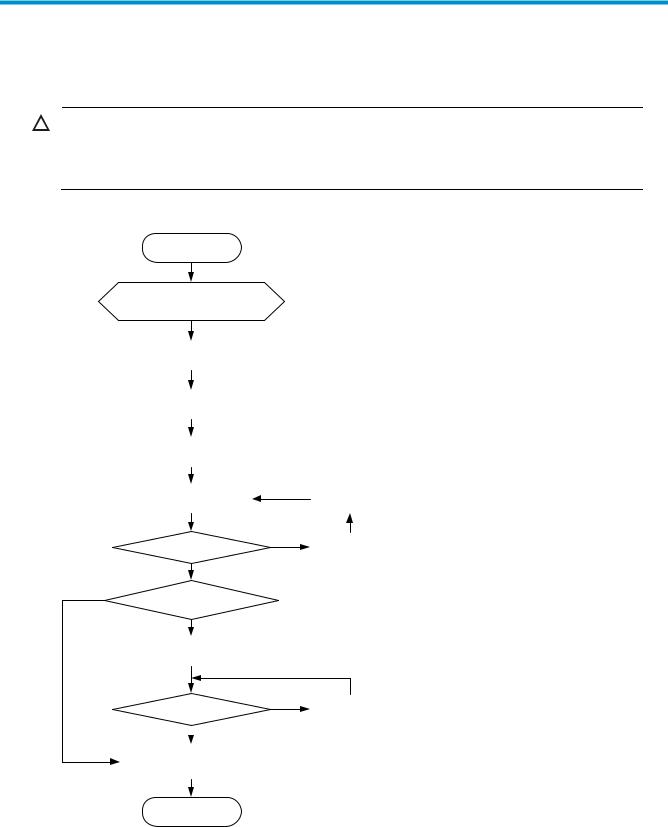
Installing the switch
CAUTION:
Keep the tamper-proof seal on a mounting screw on the chassis cover intact, and if you want to open the chassis, contact your HP Support for permission. Otherwise, HP shall not be liable for any consequence caused thereby.
Figure 1 Hardware installation flow
Start
Install the switch to a 19-in rack or workbench
Ground the switch
Connect the power cord
Verify the installation
Power on the switch
Operating properly?
Yes
No
Install interface cards?
Yes
Install interface cards
Operating properly?  Yes
Yes
Connect transceiver modules, connectors, and cables
|
Troubleshoot |
|
|
the switch |
|
|
No |
Power off the |
|
switch |
|
No |
Troubleshoot |
|
the switch |

Rack-mounting the A5120 EI switch in a 19-inch rack
CAUTION:
Switches with 420 mm (16.54 in) depth require either a rack shelf or rear mounting brackets. Front mounting brackets alone cannot support the weight of these switches.
Table 6 shows installation methods for mounting switches of different depths in a 19-inch standard rack. The mounting position depends on the depth of the rack.
Table 6 Installation methods
|
Use front |
Use front mounting |
Use front and |
|||
|
mounting |
|||||
|
Chassis |
Depth |
brackets and a rack |
rear mounting |
||
|
brackets |
|||||
|
shelf |
brackets |
||||
|
only |
|||||
|
A5120-24G EI (2 slots) |
Yes (see |
||||
|
A5120-24G EI TAA (2 slots) |
«Rack- |
Yes (see «Rack- |
|||
|
300 mm |
mounting |
||||
|
A5120-48G EI (2 slots) |
mounting using front |
||||
|
(11.81 |
using only |
No |
|||
|
A5120-48G EI TAA (2 slots) |
mounting brackets and |
||||
|
in) |
front |
||||
|
a rack shelf«) |
|||||
|
A5120-24G EI |
mounting |
||||
|
A5120-48G EI |
brackets« |
||||
|
A5120-24G-PoE+ EI (2 slots) |
|||||
|
A5120-24G-PoE+ EI TAA (2 |
Yes (see «Rack- |
Yes (see «Rack- |
|||
|
420 mm |
mounting by |
||||
|
slots) |
mounting using front |
||||
|
(16.54 |
No |
using front and |
|||
|
A5120-48G-PoE+ EI (2 slots) |
mounting brackets and |
||||
|
in) |
rear mounting |
||||
|
a rack shelf«) |
|||||
|
A5120-48G-PoE+ EI TAA (2 |
brackets«) |
||||
slots)
Mounting brackets
NOTE:
The M6 screws for fastening the brackets to a rack are user-supplied.
5
![]()
Mounting bracket views
Figure 2 Front mounting bracket
1
2
(1)Hole for attaching to a rack (by using an M6 screw)
(2)Hole for attaching to the switch chassis
Figure 3 Rear mounting bracket
1
(1) Hole for attaching to a rack (by using an M6 screw)
Mounting brackets shipped with different switch models
Table 7 shows the mounting brackets included with different switch models.
Table 7 Mounting bracket kit shipped with the A5120 EI switches
|
Chassis |
Front mounting brackets |
Rear mounting brackets |
||
|
A5120-24G EI (2 slots) |
||||
|
A5120-24G EI TAA (2 slots) |
||||
|
A5120-48G EI (2 slots) |
One pair |
N/A |
||
|
A5120-48G |
EI TAA (2 slots) |
|||
|
A5120-24G |
EI |
|||
|
A5120-48G |
EI |
|||
6
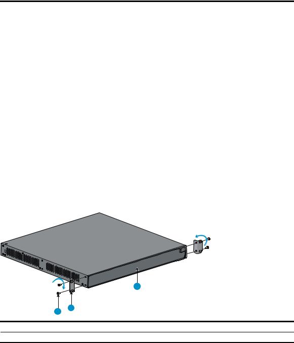
|
Chassis |
Front mounting brackets |
Rear mounting brackets |
|
|
A5120-24G-PoE+ EI (2 slots) |
|||
|
A5120-24G-PoE+ EI TAA (2 slots) |
One pair |
One pair |
|
|
A5120-48G-PoE+ EI (2 slots) |
|||
|
A5120-48G-PoE+ EI TAA (2 slots) |
|||
Rack-mounting using only front mounting brackets
Use this installation method only for A5120-24G EI (2 slots), A5120-24G EI TAA (2 slots), A5120-48G EI (2 slots), A5120-48G EI TAA (2 slots), A5120-24G EI, and A5120-48G EI switches.
To mount a switch in a 19-inch standard rack using only front mounting brackets (requires two people):
1.Wear an ESD-preventive wrist strap and make sure it makes good skin contact and is properly grounded.
2.Check that the rack is properly grounded and can support the weight of the switch chassis and all its accessories.
3.Unpack the front mounting brackets and the screws for attaching the brackets to the switch chassis.
4.Align the round holes in one bracket with the holes in the front mounting position of the switch chassis, and use the screws to fasten the mounting brackets to the chassis, as shown in Figure 4.
Figure 4 Attach the front mounting brackets to the chassis
|
1 |
||
|
3 |
2 |
|
|
(1) Front panel of the switch |
(2) Front mounting bracket |
(3)Screw
5.Install cage nuts (user-supplied) in the mounting holes in the rack posts.
6.This step requires two people.
a.One person holds the switch chassis and aligns the oval holes in the brackets with the mounting holes in the rack posts.
b.The other person fastens the mounting brackets to the rack with user-supplied M6 screws, as shown in Figure 5.
7
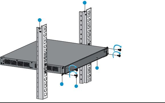
Figure 5 Attach the front mounting brackets to the rack
1
1
2
|
(1) |
Front square-holed post |
(2) |
Front panel |
|
(3) |
Screw for fastening the bracket to the square-holed post |
(4) |
Front mounting bracket |
Rack-mounting using front mounting brackets and a rack shelf
This installation method can be used for all A5120 EI switches.
To mount a switch in a 19-inch rack using the front mounting brackets and a rack shelf:
1.Wear an ESD-preventive wrist strap and make sure it makes good skin contact and is properly grounded.
2.Check that the rack is properly grounded and can support the weight of the switch chassis and all its accessories.
3.Install the rack shelf horizontally in an appropriate position in the rack.
4.Unpack the front mounting brackets and the screws for fastening the brackets to the switch chassis.
5.Align the round holes in one bracket with the holes in the front mounting position of the switch chassis, and use the removed screws to fasten the mounting bracket to the chassis, as shown in Figure 4.
6.Repeat the previous step to attach the other mounting bracket to the chassis.
7.Install cage nuts (user-supplied) in the mounting holes in the rack posts.
8.Place the switch on the rack shelf, push it into the rack until the brackets touch the rack posts, and fasten the mounting brackets with M6 screws (user-supplied) to the rack, as shown in Figure 5.
Rack-mounting by using front and rear mounting brackets
This installation method is available only for the A5120-24G-PoE+ EI (2 slots), A5120-24G-PoE+ EI TAA (2 slots), A5120-48G-PoE+ EI (2 slots), and A5120-48G-PoE+ EI TAA (2 slots) switches.
8
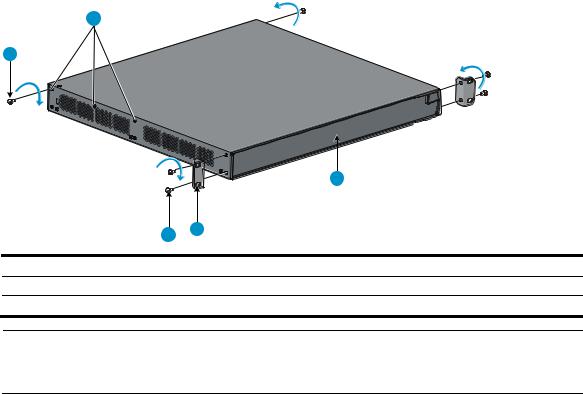
This task requires two people. To install the switch in a 19-inch rack by using the front and rear mounting brackets:
1.Wear an ESD-preventive wrist strap and make sure it makes good skin contact and is properly grounded.
2.Unpack the front mounting brackets and the screws for fastening the brackets to the switch chassis.
3.Fasten the front mounting brackets to chassis by aligning the round holes in the brackets with the holes in the front mounting position of the switch chassis, and fastening them with the removed screws, as shown in Figure 4.
4.Unpack the rear mounting brackets and the load-bearing screws.
5.Fasten the load-bearing screws in one of the rear mounting positions (see callout 2 in Figure 6) as needed.
Figure 6 Attach the front mounting brackets and load-bearing screws to the chassis
2
1
|
3 |
||||
|
5 |
4 |
|||
|
(1) |
Load-bearing screw |
(2) |
Rear mounting positions |
|
|
(3) |
Front panel |
(4) |
Front mounting bracket |
|
|
(5) |
Screw for fastening the front mounting bracket to the switch |
NOTE:
The rear mounting brackets must be in secure contact with the load-bearing screws to support the chassis weight.
6.Install cage nuts (user-supplied) in the mounting holes in the front and rear rack posts.
7.Fasten the rear mounting brackets to the rear posts with M6 screws (user supplied), as shown in Figure 7.
9
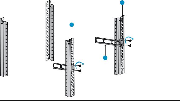
Figure 7 Attach the rear mounting brackets to a rack
1
1
2
|
(1) Rear square-holed post |
(2) Rear mounting bracket |
10
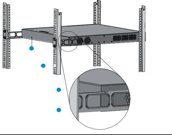
8.One person lifts the chassis, supporting it with one hand underneath and the other hand holding the front.
a.Gently push the chassis into the rack so that the load-bearing screws fit snugly over the upper edges of the rear mounting brackets.
b.Verify that the load-bearing screws fit snugly over the upper edges of the rear mounting brackets, as shown in Figure 8.
c.Continue to support the chassis until its front brackets are securely fastened to the rack.
Figure 8 Mount the switch in the rack
1
2 

3 


4 
|
(1) |
Rear panel |
(2) |
Rear square-holed post |
|
(3) |
Load-bearing screw |
(4) |
Rear mounting bracket |
9.The other person attaches the front brackets to the rack, as shown in Figure 9:
a.Align the oval holes in the front brackets with the mounting holes in the front rack posts.
b.Fasten the front mounting brackets to the front rack posts with user-supplied M6 screws.
10.Verify that front and rear mounting brackets have been installed correctly and switch is securely mounted in the rack.
11
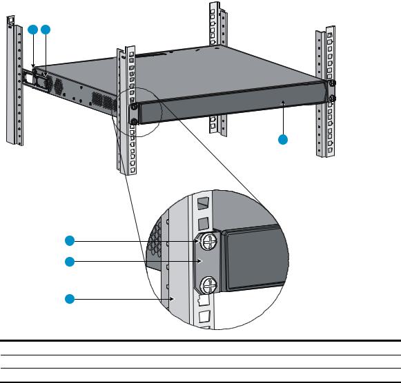
Figure 9 Attach the front brackets to the rack
3
|
4 |
|||
|
5 |
|||
|
6 |
|||
|
(1) |
Load-bearing screw |
(2) |
Rear mounting bracket |
|
(3) |
Front panel |
(4) |
A screw used to fasten the front mounting bracket to the rack |
|
(5) |
Front mounting bracket |
(6) |
Front square-holed post |
12
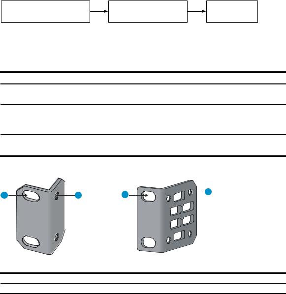
Rack-mounting the A5120 SI switch in a 19-inch rack
Figure 10 shows the general procedure for installing an A5120 SI switch in a 19-inch rack.
Figure 10 Install an A5120 SI switch in a 19-inch rack
|
Choose proper installation |
Install the mounting |
Mount the |
|
|
brackets to the left and |
|||
|
positions for mounting brackets |
switch to a rack |
||
|
right sides of the switch |
|||
Mounting brackets and mounting positions
Table 8 Mounting brackets for the A5120 SI switches
|
Chassis |
Bracket view |
Mounting position |
||
|
A5120-16G SI |
See callout A in Figure 11. |
Front mounting (see Figure 12) |
||
|
A5120-24G SI |
Rear mounting (see Figure 13) |
|||
|
A5120-24G-PoE+ SI |
Front mounting (see Figure 14) |
|||
|
See callout B in Figure 11. |
Mid-mounting (see Figure 15) |
|||
|
A5120-24G-PPoE+ SI |
||||
|
Rear mounting (see Figure 16) |
||||
|
A5120-48G SI |
See callout B in Figure 11. |
Front mounting (see Figure 14) |
||
|
Rear mounting (see Figure 16) |
||||
|
Figure 11 Mounting brackets |
||||
|
1 |
2 |
1 |
2 |
|
(1)Holes for attaching to a rack (by using M6 screws)
(2)Holes for attaching to the switch chassis
Attaching the mounting brackets to the switch chassis
To attach the mounting brackets to the switch chassis:
1.Identify the correct mounting position (see Table 8).
2.Align the round holes in one bracket with the holes in the mounting position.
3.Use screws to fasten the mounting bracket to the chassis.
13

4. Repeat the preceding steps to attach the other mounting bracket to the chassis.
Figure 12 Front mounting position (A5120-16G SI/A5120-24G SI)
1
(1) Front panel
Figure 13 Rear mounting position (A5120-16G SI/A5120-24G SI)
1
(1) Front panel
Figure 14 Front mounting position (A5120-24G-PoE+ SI/A5120-24G-PPoE+ SI/A5120-48G SI)
1
(1) Front panel
Figure 15 Mid-mounting position (A5120-24G-PoE+ SI/A5120-24G-PPoE+ SI)
1
(1) Front panel
14
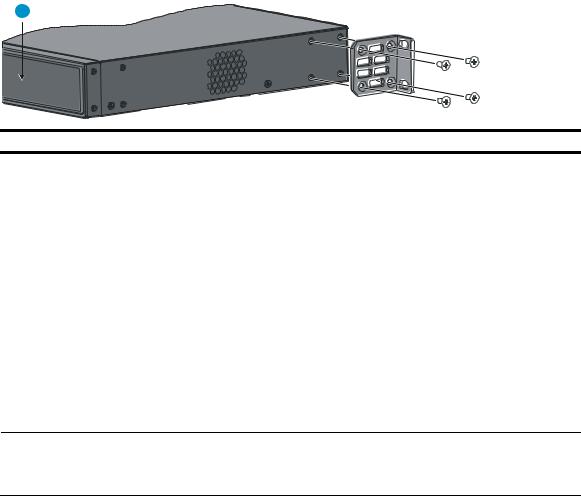
Figure 16 Rear mounting position (A5120-24G-PoE+ SI/A5120-24G-PPoE+ SI/A5120-48G SI)
1
(1) Front panel
Rack-mounting procedure
This task requires two persons. To mount the switch in a rack:
1.Wear an ESD-preventive wrist strap and make sure it makes good skin contact and is properly grounded.
2.Check that the rack is properly grounded and can support the weight of the switch chassis and all its accessories.
3.Check that the mounting brackets have been securely attached to the switch chassis.
4.Install cage nuts (user-supplied) in the mounting holes in the rack posts.
5.One person holds the switch chassis and aligns the oval holes in the brackets with the mounting holes in the rack posts, and the other person fastens the mounting brackets with M6 screws (usersupplied) to the rack, as shown in Figure 17 or Figure 18.
NOTE:
If a rack shelf is available, you can put the switch on the rack shelf, slide the switch to an appropriate location, and attach the switch to the rack with the mounting brackets.
15
![]()
Figure 17 Mount the switch in a rack (A5120-16G SI)
1
2
|
(1) Front panel |
(2) Rear panel |
Figure 18 Mount the switch in a rack (A5120-24G-PoE+ SI/A5120-24G-PPoE+ SI)
1
16
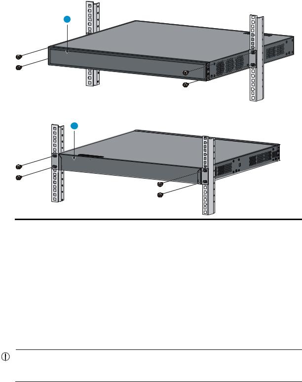
1
2
|
(1) Front panel |
(2) Rear panel |
Mounting the switch on a workbench
This installation method is available for all A5120 EI and A5120 SI switches.
To mount the switch on a workbench:
1.Check that the workbench is sturdy and properly grounded.
2.Place the switch upside-down on the workbench.
3.Clean the round holes in the chassis bottom with dry cloth.
4.Attach the rubber feet to the four round holes in the chassis bottom.
5.Place the switch upright on the workbench.
IMPORTANT:
Ensure good ventilation and 10 cm (3.9 in) of clearance around the chassis for heat dissipation. Do not place heavy objects on the switch.
17

Grounding the switch
WARNING!
Correctly connecting the switch grounding cable is crucial to lightning protection and EMI protection.
NOTE:
The power and grounding terminals shown in this section are for illustration only, and may be different from the switch’s actual power and grounding terminals.
The power input end of the switch has a noise filter, whose central ground is directly connected to the chassis to form the chassis ground (commonly known as PGND). You must securely connect this chassis ground to the earth so the faradism and leakage electricity can be safely released to the earth to minimize EMI susceptibility of the switch.
You can ground the switch in one of the following ways, depending on the grounding conditions available at the installation site:
Grounding to a grounding strip
Grounding to a buried grounding conductor
Grounding through the AC power cord
HP recommends grounding the switch to a grounding strip in the equipment room, using the grounding cable provided with the switch, whenever possible.
Grounding to a grounding strip
If a grounding strip is available at the installation site, connect the grounding cable to the grounding strip.
WARNING!
Connect the grounding cable to the equipment room’s grounding system. Do not connect it to a fire main or lightning rod.
NOTE:
An OT terminal is supplied with the A5120 EI series A5120-24G-PoE+ SI and A5120-24G-PPoE+ SI switches. For other models, the OT terminal is user-supplied.
To connect the grounding cable to the switch (the A5120-48G EI (2 slots) is shown as an example):
1.Identify the grounding point (with a grounding sign) on the rear panel of the switch chassis, and remove the grounding screw from the grounding point.
2.Thread the grounding screw through the grounding cable’s OT terminal, as shown in Figure 19.
3.Use a screwdriver to fasten the grounding screw into the grounding screw hole.
18
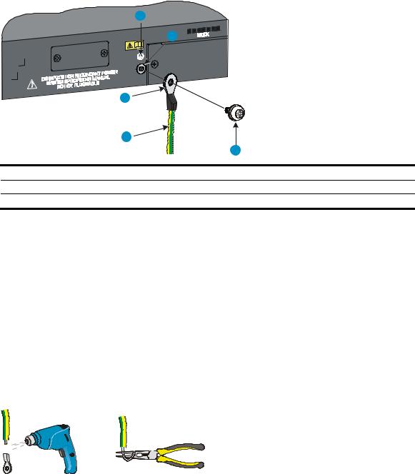
Figure 19 Connecting the grounding cable to the grounding hole of the switch chassis
1
2
|
3 |
|||
|
4 |
|||
|
5 |
|||
|
(1) |
Grounding sign |
(2) |
Grounding hole |
|
(3) |
OT terminal |
(4) |
Grounding cable |
(5)Grounding screw
4.Remove the hex nut of a grounding post on the grounding strip.
5.Cut the grounding cable as appropriate for connecting to the grounding strip.
6.Make the connector for connecting to the grounding strip:
If an OT terminal is available, peel 5 mm (0.20 in) of insulation sheath by using a wire stripper, and insert the bare metal part through the black insulation covering into the end of the OT terminal, secure the metal part of the cable to the OT terminal with a crimper, cover the joint with the insulation covering, and heat the insulation covering with a blow dryer to completely cover the metal part (see callout A in Figure 20).
If no OT terminal is available, peel the insulation sheath as appropriate using a wire stripper, and bend the bare metal part into a ring (see callout B in Figure 20). Attach the OT terminal or
the ring to the grounding strip through the grounding post, and fasten it with the removed hex nut, as shown in Figure 21.
Figure 20 Making a grounding cable connector
19
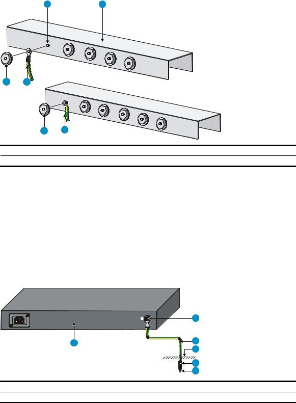
Figure 21 Connecting the grounding cable to a grounding strip
(A)
|
4 |
3 |
(B) |
|
|
(1) |
Grounding post |
(2) |
Grounding strip |
|
(3) |
Grounding cable |
(4) |
Hex nut |
Grounding to a buried grounding conductor
If the installation site has no grounding strips, but earth ground is available, hammer a 0.5 m (1.64 ft) or longer angle iron or steel tube into the earth ground to serve as a grounding conductor, as shown in Figure 22.
The dimensions of the angle iron must be at least 50 × 50 × 5 mm (1.97 × 1.97 × 0.20 in). The steel tube must be zinc-coated and its wall thickness must be at least 3.5 mm (0.14 in).
Weld the yellow-green grounding cable to the angel iron or steel tube, and treat the joint for corrosion protection.
Figure 22 Ground the switch by burying the grounding conductor into the earth ground
|
1 |
||||
|
6 |
2 |
|||
|
3 |
||||
|
4 |
||||
|
5 |
||||
|
(1) |
Grounding screw |
(2) |
Grounding cable |
(3) Earth |
|
(4) |
Joint |
(5) |
Grounding conductor |
(6) Chassis rear panel |
20
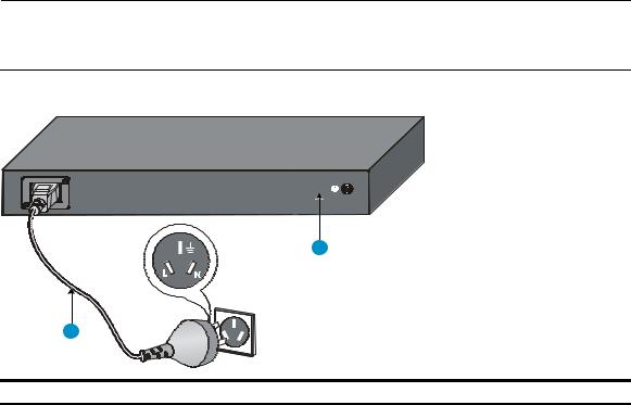
Grounding through the AC power cord
If the installation site has no grounding strips or earth ground, you can ground an AC-powered switch through the PE wire of the power cord, as shown in Figure 23.
You must make sure:
The power cord has a PE terminal.
The ground contact in the power outlet is securely connected to the ground in the power distribution room or on the AC transformer side.
The power cord is securely connected to the power outlet.
NOTE:
If the ground contact in the power outlet is not properly grounded, report the problem and reconstruct the grounding system.
Figure 23 Grounding through the PE wire of the AC power cord
2
|
1 |
|
|
(1) Three-wire AC power cable |
(2) Chassis rear panel |
21

Connecting the power cord
WARNING!
Make sure that the grounding cable has been properly connected before powering on the switch.
Use Table 9 to identify the power cord connection procedures for your switch.
Table 9 Power cord connection methods at a glance
|
Chassis |
Connection procedure |
|
|
A5120-16G SI |
||
|
A5120-24G SI |
Connecting the AC power cord |
|
|
A5120-48G SI |
||
|
A5120-24G-PPoE+ SI |
||
|
AC-input: |
||
|
A5120-24G-PoE+ SI |
Connecting the AC power cord |
|
|
RPS input: |
||
|
Connecting the switch to a –52 to –55 VDC output RPS |
||
|
A5120-24G EI (2 slots) |
||
|
A5120-24G EI TAA (2 slots) |
AC-input: |
|
|
A5120-48G EI (2 slots) |
Connecting the AC power cord |
|
|
A5120-48G EI TAA (2 slots) |
RPS input: |
|
|
A5120-24G EI |
Connecting the switch to a +12 VDC output RPS |
|
|
A5120-48G EI |
||
|
A5120-24G-PoE+ EI (2 slots) |
AC-input: |
|
|
A5120-24G-PoE+ EI TAA (2 slots) |
Connecting the AC power cord |
|
|
A5120-48G-PoE+ EI (2 slots) |
RPS input: |
|
|
A5120-48G-PoE+ EI TAA (2 slots) |
Connecting the switch to a –52 to –55 VDC output RPS |
|
Connecting the AC power cord
To connect the AC power cord:
1.Wear an ESD-preventive wrist strap and make sure it makes good skin contact and is properly grounded.
2.Connect one end of the AC power cord to the AC-input power receptacle on the switch. For examples, see Figure 24 (A5120-48G EI) and Figure 25 (A5120-24G SI).
3.Connect the other end of the AC power cord to the AC power outlet.
22
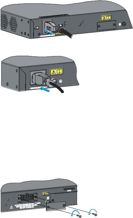
Figure 24 Connect the AC power cord to the A5120-48G EI switch
Figure 25 Connect the AC power cord to the A5120-24G SI switch
Connecting the switch to a +12 VDC output RPS
This section applies to the A5120-24G EI (2 slots), A5120-24G EI TAA (2 slots), A5120-48G EI (2 slots), A5120-48G EI TAA (2 slots), A5120-24G EI, and A5120-48G EI switches.
To connect these switches to the RPS that provides +12 VDC output:
1.Wear an ESD-preventive wrist strap and make sure it makes good skin contact and is properly grounded.
2.To use the RPS receptacle, loosen the captive screws on the RPS receptacle protective cover and remove the protective cover, as shown in Figure 26.
(If not using the RPS receptacle, leave the protective cover in place.)
Figure 26 Remove the RPS receptacle protective cover
3.The RPS cable provided with the switch has a directional plug that fits the switch’s RPS receptacle. Orient the plug to the RPS receptacle, and insert the plug as shown in Figure 27.
Do not use excessive force. The RPS receptacle is directional. If you cannot insert the plug, re-orient the plug so it fits.
4.Tighten the screws on the plug with a flat-blade screwdriver.
5.Connect the other end of the power cord to the RPS.
23
 Loading…