HP V1910 Switch Series
Product overview
HP V1910 series devices are smart-managed,
voice-ready fixed configuration Gigabit Layer 2+
switches designed for small and midsized businesses
looking for an easy-to-manage yet advanced
networking solution. The series has five models: the
HP V1910-16G, V1910-24G, V1910-48G,
V1910-24G-PoE (170 W), and V1910-24G-PoE
(365 W) Switch. Each V1910 switch has
10/100/1000 ports and an additional four true
Gigabit SFP ports. These smart-managed switches
deliver advanced features for environments not
requiring centralized administration and allow
network operation to be enhanced using an intuitive
Web-based management interface. Advanced
features include Layer 3 static routing, access control
lists for enhanced security, auto-voice VLAN, QoS
traffic prioritization, LLDP, Spanning Tree Protocols,
and Power over Ethernet models. All switches are
supported by a 3-year warranty.
Key features
b
Advanced smart-managed switching for SMBs
b
Intuitive Web interface for network enhancement
b
Layer 2+ operation with 32 static Layer 3 routes
b
PoE models with up to 365 W of PoE power
b
3-year warranty
HP
V1910 Инструкция по эксплуатации
Популярность:
9447 просмотры
Подсчет страниц:
483 страницы
Тип файла:
Размер файла:
5.92 Mb
Руководства HP V1910-48G(JE009A) Размер файлов: 1545 KB, Язык: English, Формат: pdf, Платформа: Windows/Linux, Дата: 2016-03-20
На данной странице вы можете скачать руководства HP V1910-48G(JE009A). Мы предлагаем вам ознакомиться с руководством пользователя, инструкцией по сервисному обслуживанию и ремонту.
Также здесь вы найдете список заказных номеров на комплектующие HP V1910-48G(JE009A).
Все файлы предоставляются исключительно в ознакомительных целях. И не являютя руководством по ремонту, а направлены лишь на то чтобы помочь вам более детально ознакомиться с принципом построения устройства.
Содержимое представленных здесь руководств требуют от вас знания технического английского языка.
Если вы собираетесь скачать руководство по сервисному обслуживанию HP V1910-48G(JE009A), иными словами сервис мануал, вы дожны обладать хотя бы минимальными познаниями в области электроники и пониманием базовых принципов работы электромеханических устройств.
Для просмотра руководств вам понадобится Adobe Acrobat Reader версии 9 и выше либо другая программа для просмотра pdf файлов.
В связи с популярностью информации представленной на сайте и ее бесплатного предоставления конечному пользователю, убедительная просьба использовать специальные программные продукты для многопотокового скачивания файлов.
Руководства для HP V1910-48G(JE009A)
- Руководство пользователя (User manual)
- Руководство по сервисному обслуживанию (Service manual)
- Руководство по ремонту (Repair manual)
- Перечень комплектующих (PartList)
- Manuals
- Brands
- HP Manuals
- Switch
- V1910
- Getting started manual
-
Contents
-
Table of Contents
-
Troubleshooting
-
Bookmarks
Quick Links
HP V1910 Switch Series
Getting Started Guide
59982236
Part number: 5998-2236
Document version: 6W100-20110615
Related Manuals for HP V1910 Series
Summary of Contents for HP V1910 Series
-
Page 1: Getting Started Guide
HP V1910 Switch Series Getting Started Guide 59982236 Part number: 5998-2236 Document version: 6W100-20110615…
-
Page 2
The only warranties for HP products and services are set forth in the express warranty statements accompanying such products and services. Nothing herein should be construed as constituting an additional warranty. -
Page 3
Preface The HP V1910 Switch Series Getting Started Guide describes the appearance, installation, power-on, maintenance, and troubleshooting of the HP V1910 switches. This preface includes: Audience Conventions Contacting HP Subscription service Warranty Documents Audience… -
Page 4: Subscription Service
Warranty The Hewlett-Packard Limited Warranty Statement for this product and the HP Software License Terms which apply to any software accompanying this product are available on the HP networking Web site www.hp.com/networking/warranty. The customer warranty support and services information are available on the HP networking Web site at www.hp.com/networking/support.
-
Page 5
http://www.hp.com/support/manuals… -
Page 6: Table Of Contents
Contents Product overview ·························································································································································· 1 About the HP V1910 Switch Series ································································································································ 1 HP V1910-16G Switch JE005A ······································································································································ 2 Front panel ································································································································································ 2 Rear panel ································································································································································· 3 Power supply system ················································································································································ 3 Cooling system ························································································································································· 3 HP V1910-24G Switch JE006A ······································································································································ 3 Front panel ································································································································································…
-
Page 7
Introduction to mounting brackets ························································································································ 16 Attaching the mounting brackets to the switch ··································································································· 16 Mounting the switch to a rack ······························································································································ 18 Mounting the switch on a workbench ·························································································································· 20 Grounding the switch ···················································································································································· 20 Grounding the switch with a grounding strip ····································································································· 21 Grounding the switch with a grounding conductor buried in the earth ground ·············································… -
Page 8: Product Overview
Product overview About the HP V1910 Switch Series HP V1910 Switch Series is a line of Layer 2 Gigabit Ethernet switching products developed by Hewlett-Packard Development Company, L.P. (hereinafter referred to as HP). The V1910 switches are intelligent manageable switches designed for network environments where high performance, high-density port distribution, and easy installation are required.
-
Page 9: Hp V1910-16G Switch Je005A
Rated voltage range: 100 VAC to 240 VAC, 50 Hz or 60 Hz Maximum voltage range: 90 VAC to 264 VAC, 47 Hz or 63 Hz Input Use the external RPS unit provided by HP voltage RPS DC only, with the rated voltage ranging from –52 VDC to –55 VDC…
-
Page 10: Rear Panel
Rated voltage range: 100 VAC to 240 VAC, 50 Hz or 60 Hz Input voltage range: 90 VAC to 264 VAC, 47 Hz or 63 Hz Cooling system The HP V1910- 1 6G Switch JE005A is equipped with one fan for heat dissipation HP V1910-24G Switch JE006A Front panel…
-
Page 11: Power Supply System
Rated voltage range: 100 VAC to 240 VAC, 50 Hz or 60 Hz Input voltage range: 90 VAC to 264 VAC, 47 Hz or 63 Hz Cooling system The HP V1910-24G Switch JE006A is equipped with one fan for heat dissipation. HP V1910-48G Switch JE009A Front panel…
-
Page 12: Cooling System
Rated voltage range: 100 VAC to 240 VAC, 50 Hz or 60 Hz Input voltage range: 90 VAC to 264 VAC, 47 Hz or 63 Hz Cooling system The HP V1910-24G-PoE (170W) Switch JE008A is equipped with three fans for heat dissipation.
-
Page 13: Hp V1910-24G-Poe (365W) Switch Je007A
(2) Screw hole of the plug (3) AC receptacle (4) Grounding screw Power supply system The HP V1910-24G-PoE (365W) Switch JE007A can adopt AC power input, or DC power input, or both to provide backup AC power input: Rated voltage range: 100 VAC to 240 VAC, 50 Hz or 60 Hz…
-
Page 14: Cooling System
Cooling system The HP V1910-24G-PoE (365W) Switch JE007A is equipped with six fans for heat dissipation. Ports Console port Each V1910 switch provides one console port on the front panel. Table 3 Console port specifications Item Specification Connector type RJ-45…
-
Page 15
Transceiver her. NOTE: To guarantee the functionality of the SFP ports, always use HP SFP transceiver modules on the HP V1910 Switch Series. The SFP transceiver modules available for this switch series are subject to change over time. For the most … -
Page 16: Leds
The switch has been powered off. RPS status LED The HP V1910-24G-PoE (365W) Switch JE007A provides an RPS status LED on its front panel, indicating the working status of the RPS of the switch. Table 8 Description of the RPS status LED…
-
Page 17: Port Mode Led
10/100/1000Base-T auto-sensing Ethernet port status LED NOTE: Each port of the HP V1910-48G Switch JE009A has a bi-color LED indicating its status. Each port of other models of the V1910 Switch Series has two LEDs, with only one in the ON state at a time.
-
Page 18: 1000Base-X Sfp Interface Status Led
1000Base-X SFP interface status LED NOTE: For the HP V1910-24G-PoE (170W) Switch JE008A and HP V1910-24G-PoE (365W) Switch JE007A, the port mode switching button does not take effect for the 1000Base-X SFP interface LEDs. Table 11 1000Base-X SFP interface status LEDs description…
-
Page 19: Preparing For Installation
Preparing for installation Safety recommendations To avoid any device impairment and bodily injury caused by improper use, observe these rules: Before cleaning the switch, unplug the power cord of the switch first. Do not clean the switch with wet cloth or liquid. Do not place the switch near water or in a damp environment.
-
Page 20: Cleanness
Cleanness Dust buildup on the chassis may result in electrostatic adsorption, which causes poor contact of metal components and contact points, especially when indoor relative humidity is low. In the worst case, electrostatic adsorption can cause communication failure. Table 12 Dust concentration limit in the equipment room Substance Concentration limit (particles/m Dust…
-
Page 21: Installation Tools
Installation tools Flat-blade screwdriver Phillips screwdriver ESD-preventive wrist strap All these installation tools are user supplied.
-
Page 22: Installing The Switch
Keep the tamper-proof seal on a mounting screw on the chassis cover intact, and if you want to open the chassis, contact the local agent of HP for permission. Otherwise, HP shall not be liable for any consequence caused thereby.
-
Page 23: Installing The Switch Into A 19-Inch Rack
Introduction to mounting brackets Table 14 Mounting brackets for the V1910 Switch Series Mounting Model Appearance Mounting position Description brackets HP V1910-16G Switch JE005A Provided See callout A Front or rear part of the Figure 14 by default Figure 13 chassis’s side…
-
Page 24
As shown in Table 14, the mounting brackets can be attached to the switch for front, center, or rear mounting. You can choose a proper position according to the actual requirements. Follow these steps to install a mounting bracket to the chassis: Align the mounting holes of the bracket with the holes of the chassis, as shown in Figure 14~Figure Step1… -
Page 25: Mounting The Switch To A Rack
Figure 18 Install a mounting bracket on the chassis (E) Mounting the switch to a rack Wear an ESD-preventive wrist strap and make sure the rack is well grounded and is firm enough to Step1 support the switch and cables. Locate the positions for installing cage nuts on the rack post, and use a marker to mark the positions.
-
Page 26
Figure 19 Mount the HP V1910-16G Switch JE005A to a rack Figure 20 Mount the HP V1910-24G-PoE (170W) Switch JE008A to a rack… -
Page 27: Mounting The Switch On A Workbench
NOTE: If support trays are provided on the rack, you can mount the switch to the rack with mounting brackets and trays. To do so, put the switch on the support tray and slide the switch to an appropriate location, and then fix the mounting brackets.
-
Page 28: Grounding The Switch With A Grounding Strip
CAUTION: Correctly connecting the switch grounding cable is crucial to the lightning protection and EMI protection. The power interface and grounding terminals in this section are for illustration only. The power input end of the switch has a noise filter, whose central ground is directly connected to the chassis to form the chassis ground.
-
Page 29: Grounding The Switch With A Grounding Conductor Buried In The Earth Ground
(3) Grounding cable (4) Hex nut CAUTION: Only the grounding cables supplied with the HP V1910-24G-PoE (365W) Switch JE007A and HP V1910-24G-PoE (170W) Switch JE008A provide OT terminals at the ends connecting the grounding strip. For other switch models, prepare proper OT terminals by yourself.
-
Page 30: Grounding The Switch In Other Grounding Environments
Grounding the switch in other grounding environments Grounding an AC-powered switch If the installation site has no grounding strips or earth ground, you ground an AC-powered switch through the PE wire of the AC power supply. Make sure the PE wire is well connected to the ground at the power distribution room or AC transformer side, the switch PE terminal and the PE wire are well connected, and the three-wire input cable of the grounding cable is used for the power supply cable.
-
Page 31: Connecting An Rps Dc Power Cord
Figure 25 Connect the AC power cord (A) Connecting an RPS DC power cord The HP V1910-24G-PoE (365W) Switch JE007A also supports RPS DC power input with the input voltage ranging from –52 V to –55 V. Follow these steps to install a DC power cord:…
-
Page 32: Verifying The Installation
Verifying the installation Before powering on the switch, check that: There is enough space for heat dissipation around the switch, and the rack or workbench is stable. The grounding cable is securely connected. The selected power module matches that required by the switch. …
-
Page 33: Powering On The Switch For The First Time
Powering on the switch for the first time Setting up the configuration environment To set up the configuration environment, connect a terminal (a PC in this example) to the console port on the switch with a console cable. Figure 27 Network diagram for configuration environment setup Connecting the console cable Console cable A console cable is an 8-core shielded cable, with a crimped RJ-45 connector at one end for connecting…
-
Page 34: Connection Procedure
RJ-45 Signal Direction DB-9 → → → → Connection procedure Follow these steps to connect a terminal device to the switch by using the console cable: Plug the DB-9 female connector of the console cable to the serial port of the console terminal or PC. Connect the RJ-45 connector of the console cable to the console port of the switch.
-
Page 35
Figure 29 Connection description of the HyperTerminal Type the name of the new connection in the Name text box and click OK. The following dialog box Step2 appears. Select the serial port to be used from the Connect using drop-down list. Figure 30 Set the serial port used by the HyperTerminal connection Click OK after selecting a serial port. -
Page 36
Figure 31 Set the serial port parameters Click OK after setting the serial port parameters and the system enters the HyperTerminal window shown Step4 below. Figure 32 HyperTerminal window… -
Page 37: Powering On The Switch
Powering on the switch The V1910 switches have the same Boot ROM display style. This document uses the Boot ROM output information on the HP V1910-24G Switch JE006A as an example: Starting..************************************************************************…
-
Page 38
************************************************************************ Copyright (c) 2010-2011 Hewlett-Packard Development Company, L.P. Creation Date : Jan 9 2011 CPU Type : ARM926 CPU L1 Cache : 32KB CPU Clock Speed : 333MHz Memory Type : DDR2 SDRAM Memory Size : 128MB Flash Size : 128MB CPLD Version : 001 PCB Version… -
Page 39: Changing The Boot Mode
The appearance of «Press ENTER to get started» indicates that the automatic startup of the switch is complete. Press Enter. The following prompt is displayed: <HP> You can configure the switch now. Changing the boot mode By default, the system starts up in fast boot mode. If you want to change the boot mode to normal, press…
-
Page 40
Enter your choice(0-9): Enter 0. The system reboots in normal startup mode and displays the following information: Starting..************************************************************************ HP V1910-24G Switch JE006A BOOTROM, Version 135 ************************************************************************ Copyright (c) 2010-2011 Hewlett-Packard Development Company, L.P. Creation Date : Jan 9 2011… -
Page 41
User interface aux0 is available. Press ENTER to get started. The appearance of «Press ENTER to get started» indicates that the automatic startup of the switch is complete. Press Enter. The following prompt is displayed: <HP> You can configure the switch now. -
Page 42: Maintenance And Troubleshooting
Maintenance and troubleshooting Software loading failure The switch runs with the original software version after it has failed to load new version of software. To identify and remove the loading failure cause, perform the following check procedure: Check that the physical ports are properly connected. …
-
Page 43: Power Supply Failure
Power supply failure The HP V1910-24G-PoE (365W) Switch JE007A adopts AC power input, RPS power input, or both RPS and AC power inputs. Other V1910 switches adopt AC power input only. You can look at the power LED and the RPS status LED on the front panel of the switch to identify a power system failure.
-
Page 44: Configuration Terminal Problems
Configuration terminal problems If the configuration environment setup is correct, the configuration terminal displays booting information when the switch is powered on. If the setup is incorrect, the configuration terminal would display nothing or garbled text. No terminal display If the configuration terminal displays nothing when the switch is powered on, check that: …
![]()
HP V1910 Switch Series
User Guide
*5998-2238*
Part number: 5998-2238 Document version: 2
1
The HP V1910 Switch Series User Guide describes the software features for the HP 1910 switches and guides you through the software configuration procedures. It also provides configuration examples to help you apply software features to different network scenarios.
This documentation set is intended for:
Network planners
Field technical support and servicing engineers
Network administrators working with the HP V1910 switches
Legal and notice information
© Copyright 2011 Hewlett-Packard Development Company, L.P.
No part of this documentation may be reproduced or transmitted in any form or by any means without prior written consent of Hewlett-Packard Development Company, L.P.
The information contained herein is subject to change without notice.
HEWLETT-PACKARD COMPANY MAKES NO WARRANTY OF ANY KIND WITH REGARD TO THIS MATERIAL, INCLUDING, BUT NOT LIMITED TO, THE IMPLIED WARRANTIES OF MERCHANTABILITY AND FITNESS FOR A PARTICULAR PURPOSE. Hewlett-Packard shall not be liable for errors contained herein or for incidental or consequential damages in connection with the furnishing, performance, or use of this material.
The only warranties for HP products and services are set forth in the express warranty statements accompanying such products and services. Nothing herein should be construed as constituting an additional warranty. HP shall not be liable for technical or editorial errors or omissions contained herein.
Warranty
The Hewlett-Packard Limited Warranty Statement for this product and the HP Software License Terms which apply to any software accompanying this product are available on the HP networking Web site at http://www.hp.com/networking/warranty. The customer warranty support and services information are available on the HP networking Web site at http://www.hp.com/networking/support. Additionally, your HP-authorized network reseller can provide you with assistance, both with services that they offer and with services offered by HP.
2

Contents
Overview ······································································································································································ 1
Configuration through the web interface ··················································································································· 2
Web-based network management operating environment ·····························································································2 Logging in to the web interface··········································································································································2 Default login information ··············································································································································2 Example ··········································································································································································3 Logging out of the web interface ·······································································································································4 Introduction to the web interface········································································································································4 Web user level ·····································································································································································5 Introduction to the web-based NM functions ····················································································································5 Introduction to the common items on the web pages ··································································································· 13 Configuration guidelines·················································································································································· 15
Configuration at the CLI·············································································································································16
Getting started with the CLI ············································································································································· 16 Setting up the configuration environment················································································································· 16 Setting terminal parameters ······································································································································· 17 Logging in to the CLI··················································································································································· 20 CLI commands ··································································································································································· 21 initialize ······································································································································································· 21 ipsetup·········································································································································································· 21 password ····································································································································································· 22 ping ·············································································································································································· 23 quit················································································································································································ 23 reboot··········································································································································································· 24 summary······································································································································································· 24 upgrade ······································································································································································· 25 Configuration example for upgrading the system software image at the CLI···························································· 26
Configuration wizard·················································································································································28
Overview ··········································································································································································· 28 Basic service setup···························································································································································· 28 Entering the configuration wizard homepage ········································································································· 28 Configuring system parameters································································································································· 28 Configuring management IP address ······················································································································· 29 Finishing configuration wizard·································································································································· 31
IRF stack management ···············································································································································32
Configuring stack management ······································································································································ 32 Stack management configuration task list················································································································ 32 Configuring global parameters of a stack ··············································································································· 33 Configuring stack ports ·············································································································································· 35 Displaying topology summary of a stack ················································································································· 35 Displaying device summary of a stack ····················································································································· 36 Logging into a member switch from the master switch··························································································· 36
Stack configuration example ··········································································································································· 36 Configuration guidelines·················································································································································· 42
3
Summary·····································································································································································43
Displaying device summary············································································································································· 43 Displaying system information··································································································································· 43 Displaying device information··································································································································· 44
Device basic information configuration····················································································································46
Configuring device basic information ···························································································································· 46 Configuring system name ·········································································································································· 46 Configuring idle timeout period ································································································································ 46
System time configuration··········································································································································48
Configuring system time··················································································································································· 48 System time configuration example ································································································································ 49 Configuration guidelines·················································································································································· 51
Log management configuration ································································································································52
Configuring log management ········································································································································· 52 Configuration task list················································································································································· 52 Setting syslog related parameters ····························································································································· 52 Displaying syslog························································································································································ 53 Setting loghost····························································································································································· 55
Configuration management·······································································································································56
Back up configuration ······················································································································································ 56 Restore configuration························································································································································ 56 Save configuration···························································································································································· 57 Initialize ············································································································································································· 58
Device maintenance···················································································································································59
Software upgrade····························································································································································· 59 Device reboot ···································································································································································· 60 Electronic label·································································································································································· 61 Diagnostic information ····················································································································································· 61
File management························································································································································63
File management configuration······································································································································· 63 Displaying file list························································································································································ 63 Downloading a file····················································································································································· 64 Uploading a file·························································································································································· 64 Removing a file ··························································································································································· 64
Port management configuration································································································································65
Configuring a port ···························································································································································· 65 Setting operation parameters for a port··················································································································· 65 Viewing the operation parameters of a port ··········································································································· 69 Port management configuration example ······················································································································ 70
Port mirroring configuration ······································································································································74
Introduction to port mirroring··········································································································································· 74 Implementing port mirroring ······································································································································ 74 Configuring local port mirroring ····································································································································· 75 Configuration task list················································································································································· 75 Creating a mirroring group ······································································································································· 75 Configuring ports for a mirroring group ·················································································································· 76 Configuration examples ··················································································································································· 78 Local port mirroring configuration example············································································································· 78 Configuration guidelines·················································································································································· 81
4
User management ······················································································································································82
Overview ··········································································································································································· 82 Managing users ································································································································································ 82 Adding a local user···················································································································································· 82 Setting the super password········································································································································ 83 Switching to the management level ·························································································································· 84
Loopback test configuration ······································································································································85
Overview ··········································································································································································· 85 Loopback operation·························································································································································· 85 Configuration guidelines·················································································································································· 86
VCT··············································································································································································87
Overview ··········································································································································································· 87 Testing cable status··························································································································································· 87
Flow interval configuration········································································································································89
Overview ··········································································································································································· 89 Monitoring port traffic statistics ······································································································································· 89 Setting the traffic statistics generating interval········································································································· 89 Viewing port traffic statistics······································································································································ 89
Storm constrain configuration ···································································································································91
Overview ··········································································································································································· 91 Configuring storm constrain ············································································································································ 91 Setting the traffic statistics generating interval········································································································· 91 Configuring storm constrain ······································································································································ 92
RMON configuration ·················································································································································95
Working mechanism ·················································································································································· 95 RMON groups ···························································································································································· 96 Configuring RMON·························································································································································· 97 Configuration task list················································································································································· 97 Configuring a statistics entry ····································································································································· 99 Configuring a history entry ······································································································································100
Configuring an event entry ······································································································································101
Configuring an alarm entry ·····································································································································102
Displaying RMON statistics information ················································································································104
Displaying RMON history sampling information ··································································································106
Displaying RMON event logs··································································································································108
RMON configuration example······································································································································108
Energy saving configuration··································································································································· 113
Overview ·········································································································································································113
Configuring energy saving on a port ···························································································································113
SNMP configuration ··············································································································································· 115
SNMP mechanism ····················································································································································115
SNMP protocol version ············································································································································116
SNMP configuration ·······················································································································································116
Configuration task list···············································································································································116
Enabling SNMP ························································································································································117
Configuring an SNMP view ····································································································································119
Configuring an SNMP community ··························································································································121
Configuring an SNMP group ··································································································································122
Configuring an SNMP user ·····································································································································123
5
Configuring SNMP trap function·····························································································································125
SNMP configuration example ·······································································································································127
Interface statistics ···················································································································································· 133
Overview ·········································································································································································133
Displaying interface statistics·········································································································································133
VLAN configuration ················································································································································ 135
Introduction to VLAN ················································································································································135
VLAN fundamentals··················································································································································135
VLAN types································································································································································136
Introduction to port-based VLAN·····························································································································137
Configuring a VLAN·······················································································································································138
Configuration task list···············································································································································138
Creating VLANs ························································································································································138
Selecting VLANs························································································································································139
Modifying a VLAN····················································································································································140
Modifying ports·························································································································································142
VLAN configuration example ········································································································································143
Configuration guidelines················································································································································148
VLAN interface configuration································································································································· 149
Configuring VLAN interfaces·········································································································································149
Configuration task list···············································································································································149
Creating a VLAN interface ······································································································································149
Modifying a VLAN interface····································································································································150
Voice VLAN configuration······································································································································ 153
OUI addresses···························································································································································153
Voice VLAN assignment modes ······························································································································153
Security mode and normal mode of voice VLANs ································································································155
Configuring the voice VLAN··········································································································································155
Configuration task list···············································································································································155
Configuring voice VLAN globally ···························································································································157
Configuring voice VLAN on a port·························································································································157
Adding OUI addresses to the OUI list····················································································································159
Voice VLAN configuration examples····························································································································160
Configuring voice VLAN on a port in automatic voice VLAN assignment mode ··············································160 Configuring a voice VLAN on a port in manual voice VLAN assignment mode···············································165
Configuration guidelines················································································································································171
MAC address configuration··································································································································· 172
Configuring MAC addresses·········································································································································173
Configuring a MAC address entry ·························································································································173
Setting the aging time of MAC address entries·····································································································175
MAC address configuration example···························································································································176
MSTP configuration················································································································································· 177
STP177
STP protocol packets ················································································································································177
Basic concepts in STP ···············································································································································177
How STP works ·························································································································································178
RSTP··················································································································································································184
MSTP ················································································································································································185
STP and RSTP limitations ··········································································································································185
MSTP features····························································································································································185
6
MSTP basic concepts················································································································································185
How MSTP works······················································································································································189
Implementation of MSTP on devices ·······················································································································189
Protocols and standards···········································································································································190 Configuring MSTP···························································································································································190
Configuration task list···············································································································································190
Configuring an MST region·····································································································································190
Configuring MSTP globally······································································································································192
Configuring MSTP on a port····································································································································194
Displaying MSTP information of a port ··················································································································196
MSTP configuration example·········································································································································199
Configuration guidelines················································································································································203
Link aggregation and LACP configuration ············································································································ 205
Basic concepts···························································································································································205
Link aggregation modes···········································································································································206
Load sharing mode of an aggregation group·······································································································208
Configuring link aggregation and LACP······················································································································208
Configuration task list···············································································································································208
Creating a link aggregation group·························································································································209
Displaying information of an aggregate interface································································································211 Setting LACP priority·················································································································································211
Displaying information of LACP-enabled ports······································································································212
Link aggregation and LACP configuration example ···································································································214
Configuration guidelines················································································································································217
LLDP configuration··················································································································································· 218
Background ·······························································································································································218
Basic concepts···························································································································································218
How LLDP works························································································································································222
Compatibility of LLDP with CDP·······························································································································222
Protocols and standards···········································································································································223 Configuring LLDP·····························································································································································223
LLDP configuration task list·······································································································································223
Enabling LLDP on ports·············································································································································224
Configuring LLDP settings on ports··························································································································225
Configuring global LLDP setup ································································································································229
Displaying LLDP information for a port···················································································································231
Displaying global LLDP information ························································································································236
Displaying LLDP information received from LLDP neighbors·················································································238 LLDP configuration examples ·········································································································································238
Basic LLDP configuration example ··························································································································238
CDP-compatible LLDP configuration example ········································································································244
Configuration guidelines················································································································································250
IGMP snooping configuration ································································································································ 251
Overview ·········································································································································································251
Principle of IGMP snooping·····································································································································251
IGMP snooping related ports ··································································································································251
Work mechanism of IGMP snooping ·····················································································································252
IGMP snooping querier············································································································································254
Protocols and standards···········································································································································254 Configuring IGMP snooping··········································································································································254
Configuration task list···············································································································································254
7
Enabling IGMP snooping globally··························································································································255 Configuring IGMP snooping in a VLAN ················································································································256
Configuring IGMP snooping port functions ···········································································································257
Display IGMP snooping multicast entry information ·····························································································258
IGMP snooping configuration example························································································································259
Routing configuration·············································································································································· 266
Routing table ·····························································································································································266
Static route·································································································································································266
Default route ······························································································································································267
Configuring IPv4 routing················································································································································267
Displaying the IPv4 active route table ····················································································································267
Creating an IPv4 static route ···································································································································268
Static route configuration example ·······························································································································269
Precautions ······································································································································································273
DHCP overview ······················································································································································· 274
Introduction to DHCP······················································································································································274
DHCP address allocation···············································································································································274 Allocation mechanisms·············································································································································274
Dynamic IP address allocation process··················································································································275
IP address lease extension·······································································································································275
DHCP message format ···················································································································································276
DHCP options··································································································································································277
DHCP options overview ···········································································································································277
Introduction to DHCP options ··································································································································277
Introduction to Option 82 ········································································································································277
Protocols and standards·················································································································································278
DHCP relay agent configuration···························································································································· 279
Introduction to DHCP relay agent ·································································································································279
Application environment ··········································································································································279
Fundamentals ····························································································································································279
DHCP relay agent configuration task list······················································································································280
Enabling DHCP and configuring advanced parameters for the DHCP relay agent················································281 Creating a DHCP server group ·····································································································································282
Enabling the DHCP relay agent on an interface ·········································································································283
Configuring and displaying clients’ IP-to-MAC bindings····························································································284
DHCP relay agent configuration example ···················································································································285
DHCP snooping configuration ······························································································································· 288
DHCP snooping overview··············································································································································288 Functions of DHCP snooping···································································································································288
Application environment of trusted ports················································································································289
DHCP snooping support for Option 82 ·················································································································290
DHCP snooping configuration task list ·························································································································290
Enabling DHCP snooping ··············································································································································291
Configuring DHCP snooping functions on an interface······························································································293
Displaying clients’ IP-to-MAC bindings·························································································································293 DHCP snooping configuration example·······················································································································294
Service management configuration ······················································································································· 299
Configuring service management ·································································································································300
Diagnostic tools······················································································································································· 302
Ping ············································································································································································302
8
Trace route·································································································································································302
Diagnostic tool operations ·············································································································································303
Ping operation···························································································································································303
Trace route operation···············································································································································304
ARP management···················································································································································· 306
ARP overview ··································································································································································306
ARP function ······························································································································································306
ARP message format·················································································································································306
ARP operation ···························································································································································307
ARP table ···································································································································································307
Managing ARP entries····················································································································································308 Displaying ARP entries ·············································································································································308
Creating a static ARP entry······································································································································309
Static ARP configuration example···························································································································309
Gratuitous ARP ································································································································································313
Introduction to gratuitous ARP ·································································································································313
Configuring gratuitous ARP ·····································································································································313
ARP attack defense configuration ·························································································································· 315
ARP detection ··································································································································································315
Introduction to ARP detection···································································································································315
Configuring ARP detection·······································································································································317
Creating a static binding entry································································································································319
802.1X fundamentals ············································································································································· 320
Architecture of 802.1X···················································································································································320
Controlled/uncontrolled port and port authorization status·······················································································320
802.1X-related protocols ···············································································································································321
Packet formats ···························································································································································321
EAP over RADIUS······················································································································································323
Initiating 802.1X authentication····································································································································323
802.1X client as the initiator ···································································································································323
Access device as the initiator ··································································································································323
802.1X authentication procedures ·······························································································································324
A comparison of EAP relay and EAP termination ·································································································324
EAP relay ···································································································································································325
EAP termination·························································································································································327
802.1X configuration ············································································································································· 328
HP implementation of 802.1X·······································································································································328
Access control methods············································································································································328
Using 802.1X authentication with other features··································································································328
Configuring 802.1X ·······················································································································································329
Configuration prerequisites······································································································································329 802.1X configuration task list ·································································································································330
Configuring 802.1X globally ··································································································································330
Configuring 802.1X on a port ································································································································332
Configuration examples ·················································································································································334
802.1X configuration example ·······························································································································334
ACL assignment configuration example·················································································································341
AAA configuration ·················································································································································· 351
Overview ·········································································································································································351
Introduction to AAA··················································································································································351
9
Domain-based user management····························································································································352
Configuring AAA ····························································································································································352
Configuration prerequisites······································································································································352 Configuration task list···············································································································································352
Configuring an ISP domain ·····································································································································353
Configuring authentication methods for the ISP domain ······················································································354
Configuring authorization methods for the ISP domain························································································355
Configuring accounting methods for the ISP domain ···························································································356
AAA configuration example ··········································································································································358
RADIUS configuration ············································································································································· 363
Introduction to RADIUS·············································································································································363
Client/server model··················································································································································363
Security and authentication mechanisms ···············································································································363
Basic message exchange process of RADIUS ·······································································································364
RADIUS packet format··············································································································································365
Extended RADIUS attributes·····································································································································367
Protocols and standards···········································································································································368 Configuring RADIUS·······················································································································································368 Configuration task list···············································································································································368
Configuring RADIUS servers····································································································································369
Configuring RADIUS parameters ····························································································································370
RADIUS configuration example·····································································································································373
Configuration guidelines················································································································································378
Users ········································································································································································ 379
Configuring users····························································································································································379
Configuring a local user ··········································································································································379
Configuring a user group ········································································································································381
PKI configuration ····················································································································································· 383
PKI overview····································································································································································383
PKI terms ····································································································································································383
Architecture of PKI ····················································································································································383
Applications of PKI ···················································································································································384
Operation of PKI ·······················································································································································385
Configuring PKI·······························································································································································385
Configuration task list···············································································································································385
Creating a PKI entity·················································································································································388
Creating a PKI domain·············································································································································389
Generating an RSA key pair ···································································································································392
Destroying the RSA key pair····································································································································392
Retrieving a certificate··············································································································································393 Requesting a local certificate···································································································································395
Retrieving and displaying a CRL·····························································································································396
PKI configuration example·············································································································································397
Configuring a PKI entity to request a certificate from a CA·················································································397
Configuration guidelines················································································································································402
Port isolation group configuration·························································································································· 403
Overview ·········································································································································································403
Configuring a port isolation group ·······························································································································403
Port isolation group configuration example·················································································································404
10
Authorized IP configuration···································································································································· 406
Overview ·········································································································································································406
Configuring authorized IP··············································································································································406 Authorized IP configuration example ···························································································································407
Authorized IP configuration example ·····················································································································407
ACL configuration ··················································································································································· 410
ACL overview ··································································································································································410
Introduction to IPv4 ACL···········································································································································410
Effective period of an ACL·······································································································································411
ACL step·····································································································································································412
Configuring an ACL························································································································································412
Configuration task list···············································································································································412
Configuring a time range ········································································································································413
Creating an IPv4 ACL···············································································································································414
Configuring a rule for a basic IPv4 ACL ················································································································414
Configuring a rule for an advanced IPv4 ACL ······································································································416
Configuring a rule for an Ethernet frame header ACL··························································································419
Configuration guidelines················································································································································421
QoS configuration··················································································································································· 422
Introduction to QoS ························································································································································422
Networks without QoS guarantee ··························································································································422
QoS requirements of new applications ··················································································································422
Congestion: causes, impacts, and countermeasures ····························································································422
End-to-end QoS ·························································································································································424
Traffic classification ··················································································································································424
Packet precedences ··················································································································································425
Queue scheduling·····················································································································································427
Line rate ·····································································································································································429
Priority mapping ·······················································································································································430
Introduction to priority mapping tables ··················································································································431
QoS configuration ··························································································································································432
Configuration task lists ·············································································································································432
Creating a class ························································································································································434
Configuring match criteria·······································································································································435
Creating a traffic behavior ······································································································································437
Configuring traffic mirroring and traffic redirecting for a traffic behavior·························································438
Configuring other actions for a traffic behavior····································································································439
Creating a policy······················································································································································440
Configuring classifier-behavior associations for the policy··················································································440 Applying a policy to a port ·····································································································································441
Configuring queue scheduling on a port ···············································································································442
Configuring line rate on a port ·······························································································································443
Configuring priority mapping tables ······················································································································444
Configuring priority trust mode on a port ··············································································································445
Configuration guidelines················································································································································447
ACL/QoS configuration examples ························································································································ 448
ACL/QoS configuration example ·································································································································448
PoE configuration ···················································································································································· 458
PoE overview···································································································································································458
Advantages ·······························································································································································458
Composition ······························································································································································458
11
Protocol specification ···············································································································································459
Configuring PoE······························································································································································459
Configuring PoE ports ··············································································································································459
Configuring non-standard PD detection ·················································································································461
Displaying information about PSE and PoE ports··································································································462 PoE configuration example ············································································································································462
Support and other resources ·································································································································· 465
Contacting HP ·································································································································································465
Related information·························································································································································465
Conventions·····································································································································································465 Subscription service························································································································································466
Index ········································································································································································ 467
12

Overview
The HP V1910 Switch Series can be configured through the command line interface (CLI), web interface, and SNMP/MIB. These configuration methods are suitable for different application scenarios.
The web interface supports all V1910 Switch Series configurations.
The CLI provides some configuration commands to facilitate your operation. To perform other configurations not supported by the CLI, use the web interface.
1
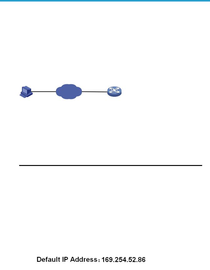
Configuration through the web interface
Web-based network management operating environment
HP provides the web-based network management function to facilitate the operations and maintenance on HP’s network devices. Through this function, the administrator can visually manage and maintain network devices through the web-based configuration interfaces.
a.Web-based network management operating environment
Logging in to the web interface
Default login information
The device is provided with the default Web login information. You can use the default information to log in to the web interface.
1.The default web login information
|
Information needed at login |
Default value |
|
|
Username |
admin |
|
|
Password |
None |
|
|
IP address of the device (VLAN-interface 1) |
Default IP address of the device, depending on the status |
|
|
of the network where the device resides. |
||
Table 1 The device is not connected to the network, or no DHCP server exists in the subnet where the device resides
If the device is not connected to the network, or no DHCP server exists in the subnet where the device resides, you can get the default IP address of the device on the label on the device, as shown in b. The default subnet mask is 255.255.0.0.
b.Default IP address of the device
2
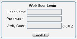
Table 2 A DHCP server exists in the subnet where the device resides
If a DHCP server exists in the subnet where the device resides, the device will dynamically obtain its default IP address through the DHCP server. You can log in to the device through the console port, and execute the summary command to view the information of its default IP address.
|
<Sysname> summary |
|
|
Select menu option: |
Summary |
|
IP Method: |
DHCP |
|
IP address: |
10.153.96.86 |
|
Subnet mask: |
255.255.255.0 |
|
Default gateway: |
0.0.0.0 |
|
<Omitted> |
Example
Assuming that the default IP address of the device is 169.254.52.86, follow these steps to log in to the device through the web interface.
Connect the device to a PC
Connect the GigabitEthernet interface of the device to a PC by using a crossover Ethernet cable (by default, all interfaces belong to VLAN 1).
Configure an IP address for the PC and ensure that the PC and device can communicate with each other properly.
Select an IP address for the PC from network segment 169.254.0.0/16 (except for the default IP address of the device), for example, 169.254.52.86.
Open the browser, and input the login information.
On the PC, open the browser (IE 5.0 or later), type the IP address http://169.254.52.86 in the address bar, and press Enter to enter the login page of the web interface, as shown in a. Input the username admin and verification code, leave the password blank, and click Login.
a.Login page of the web interface
3
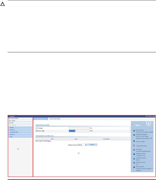
CAUTION:
The PC where you configure the device is not necessarily a web-based network management terminal. A web-based network management terminal is a PC used to log in to the web interface and is required to be reachable to the device.
After logging in to the web interface, you can select Device Users from the navigation tree, create a new user, and select Wizard or Network VLAN interface to configure the IP address of the VLAN interface acting as the management interface. For more information, see the corresponding configuration guides of these modules.
If you click the verification code displayed on the web login page, you can get a new verification code.
Up to five users can concurrently log in to the device through the web interface.
Logging out of the web interface
Click Logout in the upper-right corner of the web interface, as shown in a to quit the web console.
The system does not save the current configuration automatically. Therefore, it is recommended to save the current configuration before logout.
Introduction to the web interface
The Web interface is composed of three parts: navigation tree, title area, and body area, as shown in a.
a.Web-based configuration interface
|
(1) Navigation tree |
(2) Body area |
(3) Title area |
Navigation tree—Organizes the web-based NM functions as a navigation tree, where you can select and configure functions as needed. The result is displayed in the body area.
Body area—Allows you to configure and display features.
Title area—Displays the path of the current configuration interface in the navigation tree; provides the Help button to display the web related help information, and the Logout button to log out of the web interface.
4

CAUTION:
The web network management functions not supported by the device are not displayed in the navigation tree.
Web user level
Web user levels, from low to high, are visitor, monitor, configure, and management. A user with a higher level has all the operating rights of a user with a lower level.
Visitor—Users of this level can only use the network diagnostic tools ping and Trace Route. They can neither access the device data nor configure the device.
Monitor—Users of this level can only access the device data but cannot configure the device.
Configure—Users of this level can access device data and configure the device, but they cannot upgrade the host software, add/delete/modify users, or back up/restore configuration files.
Management—Users of this level can perform any operations to the device.
Introduction to the web-based NM functions
NOTE:
User level in 1 indicates that users of this level or users of a higher level can perform the corresponding operations.
1.Description of Web-based NM functions
|
Function menu |
Description |
User level |
|||
|
Wizard |
IP Setup |
Allows you to perform quick configuration of the |
Management |
||
|
device. |
|||||
|
Displays global settings and port settings of a |
Configure |
||||
|
stack. |
|||||
|
Setup |
|||||
|
Allows you to configure global parameters and |
Management |
||||
|
stack ports. |
|||||
|
IRF |
|||||
|
Topology |
Displays the topology summary of a stack. |
Configure |
|||
|
Summary |
|||||
|
Device |
Displays the control panels of stack members. |
Configure |
|||
|
Summary |
|||||
|
System |
Displays the basic system information, system |
Monitor |
|||
|
Information |
resource state, and recent system operation logs. |
||||
|
Summary |
|||||
|
Device |
Displays the port information of the device. |
Monitor |
|||
|
Information |
|||||
|
System Name |
Displays and allows you to configure the system |
Configure |
|||
|
Devi |
name. |
||||
|
Basic |
|||||
|
ce |
Web Idle |
Displays and allows you to configure the idle |
Configure |
||
|
Timeout |
timeout period for logged-in users. |
||||
5

|
Function menu |
Description |
User level |
|||
|
Software |
Allows you to configure to upload upgrade file |
Management |
|||
|
Upgrade |
from local host, and upgrade the system software. |
||||
|
Device |
|||||
|
Reboot |
Allows you to configure to reboot the device. |
Management |
|||
|
Maintenan |
|||||
|
Electronic Label |
Displays the electronic label of the device. |
Monitor |
|||
|
ce |
|||||
|
Diagnostic |
Generates diagnostic information file, and allows |
Management |
|||
|
Information |
you to view or save the file to local host. |
||||
|
System |
System Time |
Displays and allows you to configure the system |
Configure |
||
|
Time |
date and time. |
||||
|
Loglist |
Displays and refreshes system logs. |
Monitor |
|||
|
Allows you to clear system logs. |
Configure |
||||
|
Syslog |
|||||
|
Loghost |
Displays and allows you to configure the loghost. |
Configure |
|||
|
Log Setup |
Displays and allows you to configure the buffer |
Configure |
|||
|
capacity, and interval for refreshing system logs. |
|||||
|
Allows you to back up the configuration file to be |
|||||
|
Backup |
used at the next startup from the device to the host |
Management |
|||
|
of the current user. |
|||||
|
Configurati |
Allows you to upload the configuration file to be |
||||
|
Restore |
used at the next startup from the host of the current |
Management |
|||
|
on |
user to the device. |
||||
|
Save |
Allows you to save the current configuration to the |
Configure |
|||
|
configuration file to be used at the next startup. |
|||||
|
Initialize |
Allows you to restore the factory default settings. |
Configure |
|||
|
File |
File |
Allows you to manage files on the device, such as |
|||
|
Managem |
displaying the file list, downloading a file, |
Management |
|||
|
Management |
|||||
|
ent |
uploading a file, and removing a file. |
||||
|
Summary |
Displays port information by features. |
Monitor |
|||
|
Port |
|||||
|
Detail |
Displays feature information by ports. |
Monitor |
|||
|
Managem |
|||||
|
ent |
Setup |
Allows you to create, modify, delete, and |
Configure |
||
|
enable/disable a port, and clear port statistics. |
|||||
|
Summary |
Displays the configuration information of a port |
Monitor |
|||
|
mirroring group. |
|||||
|
Port |
Create |
Allows you to create a port mirroring group. |
Configure |
||
|
Mirroring |
Remove |
Allows you to remove a port mirroring group. |
Configure |
||
|
Modify Port |
Allows you to configure ports for a mirroring |
Configure |
|||
|
group. |
|||||
|
Summary |
Displays the brief information of FTP and Telnet |
Monitor |
|||
|
users. |
|||||
|
Users |
Allows you to configure a password for a |
||||
|
Super Password |
lower-level user to switch from the current access |
Management |
|||
|
level to the management level. |
|||||
|
Create |
Allows you to create an FTP or Telnet user. |
Management |
|||
6

|
Function menu |
Description |
User level |
||
|
Modify |
Allows you to modify FTP or Telnet user |
Management |
||
|
information. |
||||
|
Remove |
Allows you to remove an FTP or a Telnet user. |
Management |
||
|
Switch To |
Allows you to switch the current user level to the |
Visitor |
||
|
Management |
management level. |
|||
|
Loopback |
Loopback |
Allows you to perform loopback tests on Ethernet |
Configure |
|
|
interfaces. |
||||
|
VCT |
VCT |
Allows you to check the status of the cables |
Configure |
|
|
connected to Ethernet ports. |
||||
|
Port Traffic |
Displays the average rate at which the interface |
|||
|
receives and sends packets within a specified time |
Monitor |
|||
|
Flow |
Statistics |
|||
|
interval. |
||||
|
Interval |
||||
|
Interval |
Allows you to set an interval for collecting traffic |
Configure |
||
|
Configuration |
statistics on interfaces. |
|||
|
Displays and allows you to set the interval for |
||||
|
Storm |
Storm Constrain |
collecting storm constrain statistics. |
Configure |
|
|
Constrain |
Displays, and allows you to create, modify, and |
|||
|
remove the port traffic threshold. |
||||
|
Statistics |
Displays, and allows you to create, modify, and |
Configure |
||
|
clear RMON statistics. |
||||
|
History |
Displays, and allows you to create, modify, and |
Configure |
||
|
clear RMON history sampling information. |
||||
|
RMON |
Alarm |
Allows you to view, create, modify, and clear |
Configure |
|
|
alarm entries. |
||||
|
Event |
Allows you to view, create, modify, and clear event |
Configure |
||
|
entries. |
||||
|
Log |
Displays log information about RMON events. |
Configure |
||
|
Energy |
Energy Saving |
Displays and allows you to configure the energy |
Configure |
|
|
Saving |
saving settings of an interface. |
|||
|
Displays and refreshes SNMP configuration and |
Monitor |
|||
|
Setup |
statistics information. |
|||
|
Allows you to configure SNMP. |
Configure |
|||
|
Displays SNMP community information. |
Monitor |
|||
|
Community |
||||
|
Allows you to create, modify and delete an SNMP |
Configure |
|||
|
community. |
||||
|
SNMP |
||||
|
Displays SNMP group information. |
Monitor |
|||
|
Group |
||||
|
Allows you to create, modify and delete an SNMP |
Configure |
|||
|
group. |
||||
|
Displays SNMP user information. |
Monitor |
|||
|
User |
||||
|
Allows you to create, modify and delete an SNMP |
Configure |
|||
|
user. |
||||
7

|
Function menu |
Description |
User level |
|||
|
Displays the status of the SNMP trap function and |
Monitor |
||||
|
information about target hosts. |
|||||
|
Trap |
|||||
|
Allows you to enable or disable the SNMP trap |
Configure |
||||
|
function, or create, modify and delete a target host. |
|||||
|
Displays SNMP view information. |
Monitor |
||||
|
View |
|||||
|
Allows you to create, modify and delete an SNMP |
Configure |
||||
|
view. |
|||||
|
Interface |
Interface |
Displays and allows you to clear the statistics |
Configure |
||
|
Statistics |
Statistics |
information of an interface. |
|||
|
Select VLAN |
Allows you to select a VLAN range. |
Monitor |
|||
|
Create |
Allows you to create VLANs. |
Configure |
|||
|
Port Detail |
Displays the VLAN-related details of a port. |
Monitor |
|||
|
Detail |
Displays the member port information of a VLAN. |
Monitor |
|||
|
VLAN |
|||||
|
Modify VLAN |
Allows you to modify the description and member |
Configure |
|||
|
ports of a VLAN. |
|||||
|
Modify Port |
Allows you to change the VLAN to which a port |
Configure |
|||
|
belongs. |
|||||
|
Remove |
Allows you to remove VLANs. |
Configure |
|||
|
Summary |
Displays information about VLAN interfaces by |
Monitor |
|||
|
address type. |
|||||
|
VLAN |
Create |
Allows you to create VLAN interfaces and |
Configure |
||
|
configure IP addresses for them. |
|||||
|
Interface |
|||||
|
Modify |
Allows you to modify the IP addresses and status of |
Configure |
|||
|
VLAN interfaces. |
|||||
|
Net |
|||||
|
Remove |
Allows you to remove VLAN interfaces. |
Configure |
|||
|
work |
|||||
|
Summary |
Displays voice VLAN information globally or on a |
Monitor |
|||
|
port. |
|||||
|
Setup |
Allows you to configure the global voice VLAN. |
Configure |
|||
|
Port Setup |
Allows you to configure a voice VLAN on a port. |
Configure |
|||
|
Voice |
|||||
|
OUI Summary |
Displays the addresses of the OUIs that can be |
Monitor |
|||
|
VLAN |
|||||
|
identified by voice VLAN. |
|||||
|
OUI Add |
Allows you to add the address of an OUI that can |
Configure |
|||
|
be identified by voice VLAN. |
|||||
|
OUI Remove |
Allows you to remove the address of an OUI that |
Configure |
|||
|
can be identified by voice VLAN. |
|||||
|
MAC |
Displays MAC address information. |
Monitor |
|||
|
MAC |
Allows you to create and remove MAC addresses. |
Configure |
|||
|
Setup |
Displays and allows you to configure MAC address |
Configure |
|||
|
aging time. |
|||||
|
MSTP |
Region |
Displays information about MST regions. |
Monitor |
||
8
![]()
|
Function menu |
Description |
User level |
||
|
Allows you to modify MST regions. |
Configure |
|||
|
Global |
Allows you to set global MSTP parameters. |
Configure |
||
|
Port Summary |
Displays the MSTP information of ports. |
Monitor |
||
|
Port Setup |
Allows you to set MSTP parameters on ports. |
Configure |
||
|
Summary |
Displays information about link aggregation |
Monitor |
||
|
groups. |
||||
|
Link |
||||
|
Create |
Allows you to create link aggregation groups. |
Configure |
||
|
Aggregati |
||||
|
on |
Modify |
Allows you to modify link aggregation groups. |
Configure |
|
|
Remove |
Allows you to remove link aggregation groups. |
Configure |
||
|
Summary |
Displays information about LACP-enabled ports |
Monitor |
||
|
LACP |
and their partner ports. |
|||
|
Setup |
Allows you to set LACP priorities. |
Configure |
||
|
Displays the LLDP configuration information, local |
||||
|
Port Setup |
information, neighbor information, statistics |
Monitor |
||
|
information, and status information of a port. |
||||
|
Allows you to modify LLDP configuration on a port. Configure |
||||
|
LLDP |
Global Setup |
Displays global LLDP configuration information. |
Monitor |
|
|
Allows you to configure global LLDP parameters. |
Configure |
|||
|
Global |
Displays global LLDP local information and |
Monitor |
||
|
Summary |
statistics. |
|||
|
Neighbor |
Displays global LLDP neighbor information. |
Monitor |
||
|
Summary |
||||
|
Displays global IGMP snooping configuration |
||||
|
information or the IGMP snooping configuration |
Monitor |
|||
|
information in a VLAN, and allows you to view the |
||||
|
Basic |
||||
|
IGMP snooping multicast entry information. |
||||
|
IGMP |
||||
|
Allows you to configure IGMP snooping globally or |
Configure |
|||
|
Snooping |
in a VLAN. |
|||
|
Displays the IGMP snooping configuration |
Monitor |
|||
|
Advanced |
information on a port. |
|||
|
Allows you to configure IGMP snooping on a port. Configure |
||||
|
Summary |
Displays the IPv4 active route table. |
Monitor |
||
|
IPv4 |
||||
|
Create |
Allows you to create an IPv4 static route. |
Configure |
||
|
Routing |
||||
|
Remove |
Allows you to delete the selected IPv4 static routes. |
Configure |
||
|
Displays information about the DHCP status, |
||||
|
advanced configuration information of the DHCP |
||||
|
DHCP |
DHCP Relay |
relay agent, DHCP server group configuration, |
Monitor |
|
|
DHCP relay agent interface configuration, and the |
||||
|
DHCP client information. |
||||
9

|
Function menu |
Description |
User level |
|
Allows you to enable/disable DHCP, configure |
||
|
advanced DHCP relay agent settings, configure a |
Configure |
|
|
DHCP server group, and enable/disable the DHCP |
||
|
relay agent on an interface. |
||
|
Displays the status, trusted and untrusted ports and |
Monitor |
|
|
DHCP client information of DHCP snooping. |
||
|
Allows you to enable/disable DHCP snooping, |
||
|
and configure DHCP snooping trusted and |
Configure |
|
|
untrusted ports. |
|
Displays the states of services: enabled or |
Configure |
||||
|
disabled. |
|||||
|
Service |
Service |
||||
|
Allows you to enable/disable services, and set |
Management |
||||
|
related parameters. |
|||||
|
Diagnostic |
Ping |
Allows you to ping an IPv4 address. |
Visitor |
||
|
Tools |
Trace Route |
Allows you to perform trace route operations. |
Visitor |
||
|
Displays ARP table information. |
Monitor |
||||
|
ARP Table |
|||||
|
Allows you to add, modify, and remove ARP |
Configure |
||||
|
ARP |
|||||
|
entries. |
|||||
|
Managem |
|||||
|
Displays the configuration information of gratuitous |
|||||
|
ent |
Monitor |
||||
|
Gratuitous ARP |
ARP. |
||||
|
Allows you to configure gratuitous ARP. |
Configure |
||||
|
ARP |
ARP Detection |
Displays ARP detection configuration information. |
Monitor |
||
|
Anti-Attack |
Allows you to configure ARP detection. |
Configure |
|||
|
Displays 802.1X configuration information |
Monitor |
||||
|
globally or on a port. |
|||||
|
802.1X |
802.1X |
||||
|
Allows you to configure 802.1X globally or on a |
Configure |
||||
|
port. |
|||||
|
Domain Setup |
Displays ISP domain configuration information. |
Monitor |
|||
|
Allows you to add and remove ISP domains. |
Management |
||||
|
Auth |
Displays the authentication configuration |
Monitor |
|||
|
information of an ISP domain. |
|||||
|
entic |
Authentication |
||||
|
ation |
Allows you to specify authentication methods for an |
||||
|
Management |
|||||
|
ISP domain. |
|||||
|
AAA |
|||||
|
Displays the authorization method configuration |
Monitor |
||||
|
information of an ISP domain. |
|||||
|
Authorization |
|||||
|
Allows you to specify authorization methods for an |
Management |
||||
|
ISP domain. |
|||||
|
Accounting |
Displays the accounting method configuration |
Monitor |
|||
|
information of an ISP domain. |
|||||
10

|
Function menu |
Description |
User level |
|||
|
Allows you to specify accounting methods for an |
Management |
||||
|
ISP domain. |
|||||
|
RADIUS Server |
Displays and allows you to configure RADIUS |
Management |
|||
|
server information. |
|||||
|
RADIUS |
|||||
|
RADIUS Setup |
Displays and allows you to configure RADIUS |
Management |
|||
|
parameters. |
|||||
|
Displays configuration information about local |
Monitor |
||||
|
users. |
|||||
|
Local User |
|||||
|
Allows you to create, modify and remove a local |
Management |
||||
|
user. |
|||||
|
Users |
|||||
|
Displays configuration information about user |
Monitor |
||||
|
groups. |
|||||
|
User Group |
|||||
|
Allows you to create, modify and remove a user |
Management |
||||
|
group. |
|||||
|
Entity |
Displays information about PKI entities. |
Monitor |
|||
|
Allows you to add, modify, and delete a PKI entity. |
Configure |
||||
|
Displays information about PKI domains. |
Monitor |
||||
|
Domain |
|||||
|
Allows you to add, modify, and delete a PKI |
Configure |
||||
|
domain. |
|||||
|
PKI |
Displays the certificate information of PKI domains |
Monitor |
|||
|
and allows you to view the contents of a certificate. |
|||||
|
Certificate |
Allows you to generate a key pair, destroy a key |
||||
|
pair, retrieve a certificate, request a certificate, and |
Configure |
||||
|
delete a certificate. |
|||||
|
CRL |
Displays the contents of the CRL. |
Monitor |
|||
|
Allows you to receive the CRL of a domain. |
Configure |
||||
|
Port Isolate |
Summary |
Displays port isolation group information. |
Monitor |
||
|
Group |
Modify |
Allows you to configure a port isolation group. |
Configure |
||
|
Secu |
|||||
|
Displays the configurations of authorized IP, the |
|||||
|
rity |
|||||
|
Authorized |
Summary |
associated IPv4 ACL list, and the associated IPv6 |
Management |
||
|
ACL list. |
|||||
|
IP |
|||||
|
Setup |
Allows you to configure authorized IP. |
Management |
|||
|
Summary |
Displays time range configuration information. |
Monitor |
|||
|
Time |
|||||
|
Create |
Allows you to create a time range. |
Configure |
|||
|
Range |
|||||
|
Remove |
Allows you to delete a time range. |
Configure |
|||
|
QoS |
Summary |
Displays IPv4 ACL configuration information. |
Monitor |
||
|
Create |
Allows you to create an IPv4 ACL. |
Configure |
|||
|
ACL IPv4 |
|||||
|
Basic Setup |
Allows you to configure a rule for a basic IPv4 ACL. |
Configure |
|||
|
Advanced |
Allows you to configure a rule for an advanced |
Configure |
|||
|
Setup |
IPv4 ACL. |
||||
11

|
Function menu |
Description |
User level |
|||
|
Link Setup |
Allows you to create a rule for a link layer ACL. |
Configure |
|||
|
Remove |
Allows you to delete an IPv4 ACL or its rules. |
Configure |
|||
|
Queue |
Summary |
Displays the queue information of a port. |
Monitor |
||
|
Setup |
Allows you to configure a queue on a port. |
Configure |
|||
|
Line Rate |
Summary |
Displays line rate configuration information. |
Monitor |
||
|
Setup |
Allows you to configure the line rate. |
Configure |
|||
|
Summary |
Displays classifier configuration information. |
Monitor |
|||
|
Create |
Allows you to create a class. |
Configure |
|||
|
Classifier |
Setup |
Allows you to configure the classification rules for a |
Configure |
||
|
class. |
|||||
|
Remove |
Allows you to delete a class or its classification |
Configure |
|||
|
rules. |
|||||
|
Summary |
Displays traffic behavior configuration information. |
Monitor |
|||
|
Create |
Allows you to create a traffic behavior. |
Configure |
|||
|
Setup |
Allows you to configure actions for a traffic |
Configure |
|||
|
Behavior |
behavior. |
||||
|
Port Setup |
Allows you to configure traffic mirroring and traffic |
Configure |
|||
|
redirecting for a traffic behavior |
|||||
|
Remove |
Allows you to delete a traffic behavior. |
Configure |
|||
|
Summary |
Displays QoS policy configuration information. |
Monitor |
|||
|
Create |
Allows you to create a QoS policy. |
Configure |
|||
|
QoS Policy |
Setup |
Allows you to configure the classifier-behavior |
Configure |
||
|
associations for a QoS policy. |
|||||
|
Remove |
Allows you to delete a QoS policy or its |
Configure |
|||
|
classifier-behavior associations. |
|||||
|
Summary |
Displays the QoS policy applied to a port. |
Monitor |
|||
|
Port Policy |
Setup |
Allows you to apply a QoS policy to a port. |
Configure |
||
|
Remove |
Allows you to remove the QoS policy from the port. |
Configure |
|||
|
Priority |
Priority |
Displays priority mapping table information. |
Monitor |
||
|
Mapping |
Mapping |
Allows you to modify the priority mapping entries. |
Configure |
||
|
Port Priority |
Port Priority |
Displays port priority and trust mode information. |
Monitor |
||
|
Allows you to modify port priority and trust mode. |
Configure |
||||
|
Summary |
Displays PSE information and PoE interface |
Monitor |
|||
|
PoE |
PoE |
information. |
|||
|
Setup |
Allows you to configure a PoE interface. |
Configure |
|||
12
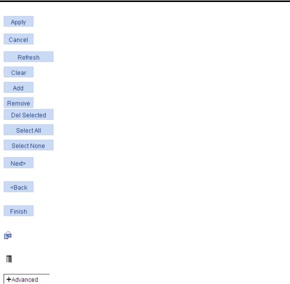
Introduction to the common items on the web pages
Buttons and icons
1.Commonly used buttons and icons
|
Button and icon |
Function |
||
|
Used to apply the configuration on the current page. |
|||
|
Used to cancel the configuration on the current page, and return to the |
|||
|
corresponding list page or the Device Info page. |
|||
|
Used to refresh the information on the current page. |
|||
|
Used to clear all the information on a list or all statistics. |
|||
|
Used to enter a page for adding an item. |
|||
|
, |
Used to remove the selected items. |
||
|
Used to select all the entries on a list, or all the ports on the device panel. |
|||
|
Used to deselect all the entries on a list, or all the ports on the device panel. |
|||
|
Generally present on the configuration wizard; used to buffer but not apply |
|||
|
the configuration of the current step and enter the next configuration step. |
|||
|
Generally present on the configuration wizard; used to buffer but not apply |
|||
|
the configuration of the current step and return to the previous configuration |
|||
|
step. |
|||
|
Generally present on the configuration wizard; used to apply the |
|||
|
configurations of all configuration steps. |
|||
|
Generally present on the “Operation” column on a list; used to enter the |
|||
|
modification page of an item so that you can modify the configurations of |
|||
|
the item. |
|||
|
Generally present on the “Operation” column on a list; used to delete the |
|||
|
item corresponding to this icon. |
|||
|
Click the plus sign before a corresponding item. You can see the collapsed |
|||
|
contents. |
|||
Page display
The web interface can display a long list by pages, as shown in a. You can set the number of entries displayed per page, and use the First, Prev, Next, and Last links to view the contents on the first, previous, next, and last pages, or go to any page that you want to view.
13

a.Content display by pages
Search function
On some list pages, the web interface provides basic and advanced search functions. You can use the search function to display those entries matching certain search criteria.
Basic search function—Select a search item from the drop-down list as shown in a, input the keyword, and click the Query button to display the entries that match the criteria.
Advanced search function—Click  before Search Item, as shown in a. You can select Match case and whole word, that is, the item to be searched must completely match the keyword, or you can select Search in previous results. If you do not select exact search, a fuzzy search is performed.
a.Advanced search
Sorting function
On some list pages, the web interface provides the sorting function to display the entries in a certain order.
As shown in a, you can click the blue heading item of each column to sort the entries based on the heading item you selected. Then, the heading item is displayed with an arrow beside it. The upward arrow indicates the ascending order, and the downward arrow indicates the descending order.
14

a.Sort display (based on MAC address in the ascending order)
Configuration guidelines
The web console supports Microsoft Internet Explorer 6.0 SP2 and higher.
The web console does not support the Back, Next, Refresh buttons provided by the browser. Using these buttons may result in abnormal display of web pages.
When the device is performing the spanning tree calculation, you cannot log in to or use the web interface.
The Windows firewall limits the number of TCP connections, so when you use IE to log in to the web interface, sometimes you may be unable to open the web interface. To avoid this problem, turn off the Windows firewall before login.
If the software version of the device changes, when you log in to the device through the web interface, delete the temporary Internet files of IE; otherwise, the web page content may not be displayed correctly.
15
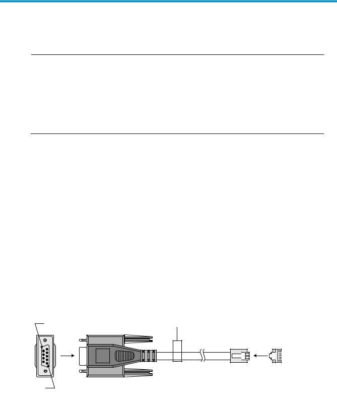
Configuration at the CLI
NOTE:
The HP V1910 Switch Series can be configured through the CLI, web interface, and SNMP/MIB, among which the web interface supports all V1910 Switch Series configurations. These configuration methods are suitable for different application scenarios. As a supplementary to the web interface, the CLI provides some configuration commands to facilitate your operation, which are described in this chapter. To perform other configurations not supported by the CLI, use the web interface.
You will enter user view directly after you log in to the device. Commands in the document are all performed in user view.
Getting started with the CLI
As a supplementary to the web interface, the CLI provides some configuration commands to facilitate your operation. For example, if you forget the IP address of VLAN-interface 1 and cannot log in to the device through the web interface, you can connect the console port of the device to a PC, and reconfigure the IP address of VLAN-interface 1 at the CLI.
This section describes using the CLI to manage the device.
Setting up the configuration environment
To set up the configuration environment, connect a terminal (a PC in this example) to the console port on the switch with a console cable.
A console cable is an 8-core shielded cable, with a crimped RJ-45 connector at one end for connecting to the console port of the switch, and a DB-9 female connector at the other end for connecting to the serial port on the console terminal.
a.Console cable
Use  a console cable to connect a terminal device to the switch, as follows:
Table 3 Plug the DB-9 female connector to the serial port of the console terminal or PC. Table 4 Connect the RJ-45 connector to the console port of the switch.
16
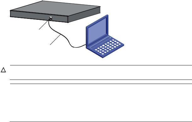
b.Network diagram for configuration environment setup
CAUTION:
Verify the mark on the console port to ensure that you are connecting to the correct port.
NOTE:
The serial port on a PC does not support hot swapping. When you connect a PC to a powered-on switch, connect the DB-9 connector of the console cable to the PC before connecting the RJ-45 connector to the switch.
When you disconnect a PC from a powered-on switch, disconnect the DB-9 connector of the console cable from the PC after disconnecting the RJ-45 connector from the switch.
Setting terminal parameters
To configure and manage the switch, you must run a terminal emulator program on the console terminal, for example, a PC. This section uses Windows XP HyperTerminal as an example.
The following are the required terminal settings:
Bits per second—38400
Data bits—8
Parity—None
Stop bits—1
Flow control—None
Emulation—VT100
Follow these steps to set terminal parameters, for example, on a Windows XP HyperTerminal:
Table 5 Select Start All Programs Accessories Communications HyperTerminal, and in the
Connection Description dialog box that appears, type the name of the new connection in the Name text box and click OK.
17
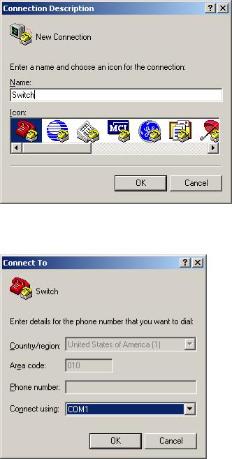
b.Connection description of the HyperTerminal
Table 6 Select the serial port to be used from the Connect using drop-down list, and click OK.
c.Set the serial port used by the HyperTerminal connection
Table 7 Set Bits per second to 38400, Data bits to 8, Parity to None, Stop bits to 1, and Flow control to
None, and click OK.
18
![]()
d.Set the serial port parameters
Table 8 Select File Properties in the HyperTerminal window.
e.HyperTerminal window
19

Table 9 Click the Settings tab, set the emulation to VT100, and click OK in the Switch Properties dialog box.
f.Set terminal emulation in Switch Properties dialog box
Logging in to the CLI
The login process requires a username and password. The default username for first time configuration is admin, no password is required. Usernames and passwords are case sensitive.
To log in to the CLI:
Table 10 Press Enter. The Username prompt displays:
Login authentication
Username:
Table 11 Enter your username at the Username prompt.
Username:admin
Table 12 Press Enter. The Password prompt display
Password:
The login information is verified, and displays the following CLI menu:
<HP V1910 Switch>
If the password is invalid, the following message appears and process restarts.
% Login failed!
20

CLI commands
This Command section contains the following commands:
|
To do… |
Use the command… |
|
|
Display a list of CLI commands on the device |
? |
|
|
Reboot the device and run the default configuration |
initialize |
|
|
Specify VLAN-interface 1 to obtain an IP address through |
ipsetup { dhcp | ip address ip-address { mask |
|
|
| mask-length } [ default-gateway |
||
|
DHCP or manual configuration |
||
|
ip-address ] } |
||
|
Modify the login password of a user |
password |
|
|
Download the Boot ROM image or system software image file |
upgrade server-address source-filename |
|
|
from the TFTP server and specify as the startup configuration |
||
|
{ bootrom | runtime } |
||
|
file |
||
|
Reboot the device and run the main configuration file |
reboot |
|
|
View the summary information of the device |
summary |
|
|
Ping a specified destination |
ping host |
|
initialize
Syntax
initialize
Parameters
None
Description
Use the initialize command to delete the current configuration file and reboot the device with the default configuration file.
Use the command with caution because it deletes the configuration file to be used at the next startup and restores the factory default settings.
Examples
# Delete the configuration file to be used at the next startup and reboot the device with the default configuration being used during reboot.
<Sysname> initialize
The startup configuration file will be deleted and the system will be rebooted.Continue? [Y/N]:y
Please wait…
ipsetup
Syntax
ipsetup { dhcp | ip address ip-address { mask | mask-length } [ default-gateway ip-address ] }
21
Parameters
dhcp: Specifies the interface to obtain an IP address through DHCP.
ip-address ip-address: Specifies an IP address for VLAN-interface 1 in dotted decimal notation. mask: Subnet mask in dotted decimal notation.
mask-length: Subnet mask length, the number of consecutive ones in the mask, in the range of 0 to 32.
default-gateway ip-address: Specifies the IP address of the default gateway or the IP address of the outbound interface. With this argument and keyword combination configured, the command not only assigns an IP address to the interface, but also specifies a default route for the device.
Description
Use the ipsetup dhcp command to specify VLAN-interface 1 to obtain an IP address through DHCP.
Use the ipsetup ip address ip-address { mask | mask-length } command to assign an IP address to VLAN-interface 1.
By default, the device automatically obtains its IP address through DHCP; if fails, it uses the assigned default IP address. For more information, see b.
If there is no VLAN-interface 1, either command creates VLAN-interface 1 first, and then specifies its IP address.
Examples
# Create VLAN-interface 1 and specify the interface to obtain an IP address through DHCP.
<Sysname> ipsetup dhcp
# Create VLAN-interface 1 and assign 192.168.1.2 to the interface, and specify 192.168.1.1 as the default gateway.
<Sysname> ipsetup ip-address 192.168.1.2 24 default-gateway 192.168.1.1
password
Syntax
password
Parameters
None
Description
Use the password command to modify the login password of a user.
Examples
# Modify the login password of user admin.
<Sysname> password
Change password for user: admin Old password: ***
Enter new password: ** Retype password: **
The password has been successfully changed.
22
ping
Syntax
ping host
Parameters
host: Destination IP address (in dotted decimal notation), URL, or host name (a string of 1 to 20 characters).
Description
Use the ping command to ping a specified destination. You can enter Ctrl+C to terminate a ping operation.
Examples
# Ping IP address 1.1.2.2.
<Sysname> ping 1.1.2.2
PING 1.1.2.2: 56 data bytes, press CTRL_C to break
Reply from 1.1.2.2: bytes=56 Sequence=1 ttl=254 time=205 ms Reply from 1.1.2.2: bytes=56 Sequence=2 ttl=254 time=1 ms Reply from 1.1.2.2: bytes=56 Sequence=3 ttl=254 time=1 ms Reply from 1.1.2.2: bytes=56 Sequence=4 ttl=254 time=1 ms Reply from 1.1.2.2: bytes=56 Sequence=5 ttl=254 time=1 ms
— 1.1.2.2 ping statistics —
5 packet(s) transmitted
5 packet(s) received
0.00% packet loss
round-trip min/avg/max = 1/41/205 ms
The output shows that IP address 1.1.2.2 is reachable and the echo replies are all returned from the destination. The minimum, average, and maximum roundtrip intervals are 1 millisecond, 41 milliseconds, and 205 milliseconds respectively.
quit
Syntax
quit
Parameters
None
Description
Use the quit command to log out of the system.
Examples
# Log out of the system.
<Sysname> quit
******************************************************************************
|
* |
Copyright (c) 2004-2011 Hewlett-Packard Development Company, L.P. |
* |
|
* |
Without the owner’s prior written consent, |
* |
23
* no decompiling or reverse-engineering shall be allowed. *
******************************************************************************
User interface aux0 is available.
Please press ENTER.
reboot
Syntax
reboot
Parameters
None
Description
Use the reboot command to reboot the device and run the main configuration file. Use this command with caution because reboot results in service interruption.
If the main configuration file is corrupted or does not exist, the device cannot be rebooted with the reboot command. In this case, you can specify a new main configuration file to reboot the device, or you can power off the device, and then power it on, and the system will automatically use the backup configuration file at the next startup.
If you reboot the device when file operations are being performed, the system does not execute the command to ensure security.
Examples
# If the configuration does not change, reboot the device.
|
<Sysname> reboot |
|
|
Start to check configuration with next startup configuration file, please wait……… |
DONE! |
|
This command will reboot the device. Continue? [Y/N]:y |
|
|
Now rebooting, please wait… |
# If the configuration changes, reboot the device.
<Sysname> reboot
Start to check configuration with next startup configuration file, please wait………DONE!
This command will reboot the device. Current configuration will be lost in next startup if you continue. Continue? [Y/N]:y
Now rebooting, please wait…
summary
Syntax
summary
Parameters
None
24
Description
Use the summary command to view the summary information of the device, including the IP address of VLAN-interface 1, and software version information.
Examples
# Display summary information of the device.
|
<Sysname> summary |
|
|
Select menu option: |
Summary |
|
IP Method: |
DHCP |
|
IP address: |
10.153.96.86 |
|
Subnet mask: |
255.255.255.0 |
|
Default gateway: |
0.0.0.0 |
Current boot app is: flash:/v1910-cmw520-a1108.bin
Next main boot app is: flash:/v1910-cmw520-a1108.bin
Next backup boot app is: NULL
HP Comware Platform Software
Comware Software, Version 5.20 Alpha 1108,
Copyright (c) 2004-2011 Hewlett-Packard Development Company, L.P.
HP V1910-24G-PoE (365W) Switch uptime is 0 week, 0 day, 6 hours, 28 minutes
HP V1910-24G-PoE (365W) Switch 128M bytes DRAM
128M bytes Nand Flash Memory Config Register points to Nand Flash
Hardware Version is REV.B CPLD Version is 002 Bootrom Version is 138
[SubSlot 0] 24GE+4SFP+POE Hardware Version is REV.B
upgrade
Syntax
upgrade server-address source-filename { bootrom | runtime }
Parameters
server-address: IP address or host name (a string of 1 to 20 characters) of a TFTP server. source-filename: Software package name on the TFTP server.
bootrom: Specifies the Boot ROM image in the software package file as the startup configuration file.
runtime: Specifies the system software image file in the software package file as the startup configuration file.
25

Description
Use the upgrade server-address source-filename bootrom command to upgrade the Boot ROM image. If the Boot ROM image in the downloaded software package file is not applicable, the original Boot ROM image is still used as the startup configuration file.
Use the upgrade server-address source-filename runtime command to upgrade the system software image file. If the system software image file in the downloaded software package file is not applicable, the original system software image file is still used as the startup configuration file.
To make the downloaded software package file take effect, reboot the device.
NOTE:
The HP V1910 Switch Series does not provide an independent Boot ROM image; instead, it integrates the Boot ROM image with the system software image file together in a software package file with the extension name of .bin.
Examples
# Download software package file main.bin from the TFTP server and use the Boot ROM image in the package as the startup configuration file.
<Sysname> upgrade 192.168.20.41 main.bin bootrom
# Download software package file main.bin from the TFTP server and use the system software image file in the package as the startup configuration file.
<Sysname> upgrade 192.168.20.41 main.bin runtime
Configuration example for upgrading the system software image at the CLI
Network requirements
As shown in a, a V1910 switch is connected to the PC through the console cable, and connected to the gateway through GigabitEthernet 1/0/1. The IP address of the gateway is 192.168.1.1/24, and the TFTP server where the system software image (SwitchV1910.bin) is located is 192.168.10.1/24. The gateway and the switch can reach each other.
The administrator upgrades the Boot ROM image and the system software image file of the V1910 switch through the PC and sets the IP address of the switch to 192.168.1.2/24.
a.Network diagram for upgrading the system software image of the V1910 switch at the CLI
Configuration procedure
Table 13 Run the TFTP server program on the TFTP server, and specify the path of the file to be loaded. (Omitted)
Table 14 Perform the following configurations on the switch.
26
# Configure the IP address of VLAN-interface 1 of the switch as 192.168.1.2/24, and specify the default gateway as 192.168.1.1.
<Switch> ipsetup ip-address 192.168.1.2 24 default-gateway 192.168.1.1
# Download the software package file SwitchV1910.bin from the TFTP server to the switch, and upgrade the system software image in the package.
<Switch> upgrade 192.168.10.1 SwitchV1910.bin runtime File will be transferred in binary mode
Downloading file from remote TFTP server, please wait…/ TFTP: 10262144 bytes received in 71 second(s)
File downloaded successfully.
# Download the software package file SwitchV1910.bin from the TFTP server to the switch, and upgrade the Boot ROM image.
<Switch> upgrade 192.168.10.1 SwitchV1910.bin bootrom
The file flash:/SwitchV1910.bin exists. Overwrite it? [Y/N]:y Verifying server file…
Deleting the old file, please wait…
File will be transferred in binary mode
Downloading file from remote TFTP server, please wait…/ TFTP: 10262144 bytes received in 61 second(s)
File downloaded successfully. BootRom file updating finished!
# Reboot the switch.
<Switch> reboot
After getting the new image file, reboot the switch to have the upgraded image take effect.
27

Configuration wizard
Overview
The configuration wizard guides you through the basic service setup, including the system name, system location, contact information, and management IP address (IP address of the VLAN interface).
Basic service setup
Entering the configuration wizard homepage
From the navigation tree, select Wizard to enter the configuration wizard homepage, as shown in a.
a.Configuration wizard homepage
Configuring system parameters
In the wizard homepage, click Next to enter the system parameter configuration page, as shown in a.
28
![]()
a.System parameter configuration page
2.System parameter configuration items
|
Item |
Description |
|
Specify the system name. |
|
|
The system name appears at the top of the navigation tree. |
|
|
Sysname |
You can also set the system name in the System Name page you enter by selecting |
|
Device Basic. For more information, see the chapter “Device basic information |
|
|
configuration”. |
|
|
Specify the physical location of the system. |
|
|
Syslocation |
You can also set the physical location in the setup page you enter by selecting Device |
|
SNMP. For more information, see the chapter “SNMP configuration”. |
|
|
Set the contact information for users to get in touch with the device vendor for help. |
|
|
Syscontact |
You can also set the contact information in the setup page you enter by selecting Device |
|
SNMP. For more information, see the chapter “SNMP configuration”. |
|
Configuring management IP address
NOTE:
Modifying the management IP address used for the current login will tear down the connection to the device. Use the new management IP address to re-log in to the system.
29

A management IP address is the IP address of a VLAN interface, which can be used to access the device. You can also set configure a VLAN interface and its IP address in the page you enter by selecting Network VLAN Interface. For more information, see the chapter “VLAN interface configuration”.
After finishing the configuration, click Next to enter the management IP address configuration page, as shown in a.
a.Management IP address configuration page
2.Management IP address configuration items
|
Item |
Description |
||
|
Select a VLAN interface. |
|||
|
Select VLAN Interface |
Available VLAN interfaces are those configured in the page you enter by selecting |
||
|
Network VLAN Interface and selecting the Create tab. |
|||
|
Enable or disable the VLAN interface. |
|||
|
When errors occurred on the VLAN interface, disable the interface and then enable |
|||
|
the port to bring the port to work properly. |
|||
|
Admin Status |
By default, the VLAN interface is in the down state if all Ethernet ports in the VLAN are |
||
|
down. The VLAN is in the up state if one or more ports in the VLAN are up. |
|||
|
IMPORTANT: |
|||
|
Disabling or enabling the VLAN interface does not affect the status of the Ethernet ports |
|||
|
in the VLAN. That is, the port status does not change with the VLAN interface status. |
|||
|
Configure IPv4 |
DHCP |
Configure how the VLAN interface obtains an IPv4 address. |
|
|
address |
DHCP: Specifies the VLAN interface to obtain an IPv4 address by |
||
|
30 |

|
Item |
Description |
||
|
BOOTP |
DHCP. |
||
|
BOOTP: Specifies the VLAN interface to obtain an IPv4 address |
|||
|
through BOOTP. |
|||
|
Manual: Allows you to specify an IPv4 address and a mask length. |
|||
|
Manual |
IMPORTANT: |
||
|
Support for IPv4 obtaining methods depends on the device model. |
|||
|
IPv4 |
Specify an IPv4 address and the mask length for the VLAN interface. |
||
|
address |
|||
|
These two text boxes are configurable if Manual is selected. |
|||
|
MaskLen |
|||
Finishing configuration wizard
After finishing the management IP address configuration, click Next, as shown in a.
a.Configuration finishes
The page displays your configurations. Review the configurations and if you want to modify the settings click Back to go back to the page. Click Finish to confirm your settings and the system then performs the configurations.
31

IRF stack management
The HP V1910 IRF stack management feature enables you to configure and monitor a stack of connected HP V1910 switches by logging in to one switch in the stack, as shown in a.
IMPORTANT:
The HP V1910 IRF stack management feature does not provide the functions of HP Intelligent Resilient Framework (IRF) technology. To avoid confusion, IRF stack management is simply called stack management in this document.
a.Network diagram for stack management
To set up a stack, you must log in to one switch to create the stack, and this switch becomes the master for the stack. You then configure and monitor all other member switches on the master switch. The ports that connect the stack member switches are called stack ports.
Configuring stack management
Stack management configuration task list
Perform the tasks in 1 to configure stack management.
1.Stack management configuration task list
|
Configuring |
Configuring global |
|
|
the master |
||
|
parameters of a |
||
|
switch of a |
||
|
stack |
||
|
stack |
||
Required
Configure a private IP address pool for a stack and establish the stack, with the switch becoming the master switch of the stack.
By default, no IP address pool is configured for a stack and no stack is established.
32

|
Task |
Remarks |
||
|
Required |
|||
|
Configuring stack |
Configure the ports of the master switch that connect to member |
||
|
ports |
switches as stack ports. |
||
|
By default, a port is not a stack port. |
|||
|
Configuring |
Required |
||
|
member |
Configuring stack |
Configure a port of a member switch that connects to the master switch |
|
|
switches of a |
ports |
or another member switch as a stack port. |
|
|
stack |
By default, a port is not a stack port. |
||
|
Displaying topology summary of a |
Optional |
||
|
stack |
Display the information of stack members. |
||
|
Optional |
|||
|
Display the control panels of stack members. |
|||
|
Displaying device summary of a stack |
IMPORTANT: |
||
|
Before viewing the control panel of a member switch, you must ensure |
|||
|
that the username, password, and access right you used to log on to the |
|||
|
master switch are the same with those configured on the member switch; |
|||
|
otherwise, the control panel of the member switch cannot be displayed. |
|||
|
Optional |
|||
|
Log in to the web interface of a member switch from the master switch. |
|||
|
IMPORTANT: |
|||
|
Logging into a member switch from |
Before logging into a member switch, you must ensure that the |
||
|
the master switch |
username, password, and access right you used to log on to the master |
switch are the same with those configured on the member switch; otherwise, you cannot log into the member switch. You can configure them by selecting Device and then clicking Users from the navigation tree.
Configuring global parameters of a stack
Select IRF from the navigation tree to enter the page shown in a. You can configure global parameters of a stack in the Global Settings area.
33

a.Setup
2.Configuration items of global parameters
Configure a private IP address pool for the stack.
The master switch of a stack must be configured with a private IP address pool to ensure that it can automatically allocate an available IP address to a member switch when the device joints the stack.
 IMPORTANT:
When you configure a private IP address pool for a stack, the number of IP addresses in the address pool needs to be equal to or greater than the number of switches to be added to the stack. Otherwise, some switches may not be able to join the stack automatically for lack of private IP addresses.
34

|
Item |
Description |
|
Enable the switch to establish a stack. |
|
|
After you enable the switch to establish a stack, the switch becomes the master switch |
|
|
of the stack and automatically adds the switches connected to its stack ports to the |
|
|
Build Stack |
stack. |
|
IMPORTANT: |
|
|
You can delete a stack only on the master switch of the stack. The Global Settings area |
|
|
on a member switch is grayed out. |
Return to Stack management configuration task list.
Configuring stack ports
Select IRF from the navigation tree to enter the page shown in a. You can configure stack ports in the Port Settings area.
Select the check box before a port name, and click Enable to configure the port as a stack port.
Select the check box before a port name, and click Disable to configure the port as a non-stack port.
Return to Stack management configuration task list.
Displaying topology summary of a stack
Select IRF from the navigation tree and click the Topology Summary tab to enter the page shown in a.
a.Topology summary
2.Fields of topology summary
|
Fields |
Description |
|
|
Member ID of the device in the stack: |
||
|
Member ID |
Value 0 indicates that the switch is the master switch of the stack. |
|
|
A value other than 0 indicates that the switch is a member switch and the value |
||
|
is the member ID of the switch in the stack. |
||
|
Role |
Role of the switch in the stack: master or member. |
|
Return to Stack management configuration task list.
35

Displaying device summary of a stack
Select IRF from the navigation tree and click the Device Summary tab to enter the page shown in a. On this page, you can view interfaces and power socket layout on the panel of each stack member by clicking the tab of the corresponding member switch.
a.Device summary (the master switch)
Return to Stack management configuration task list.
Logging into a member switch from the master switch
Select IRF from the navigation tree, click the Device Summary tab, and click the tab of a member switch to enter the page shown in a.
Click the Configuring the Device hyperlink, you can log on to the web interface of the member switch to manage and maintain the member switch directly.
a.Device summary (a member switch)
Return to Stack management configuration task list.
Stack configuration example
Network requirements
As shown in a, Switch A, Switch B, Switch C, and Switch D are connected with one another.
36

Create a stack, where Switch A is the master switch, Switch B, Switch C, and Switch D are stack members. An administrator can log in to Switch B, Switch C and Switch D through Switch A to perform remote configurations.
a.Network diagram for stack management
|
Switch A |
|||
|
Eth1/0/1 |
(Master switch) |
||
|
Stack |
Eth1/0/2 |
||
|
Eth1/0/1 |
Eth1/0/3 |
||
|
Switch B |
|||
|
Eth1/0/1 |
Eth1/0/1 |
||
|
Switch C |
Switch D |
Configuration procedure
Table 15 Configure the master switch
# Configure global parameters for the stack on Switch A.
Select IRF from the navigation tree of Switch A to enter the page of the Setup tab.
37

b.Configure global parameters for the stack on Switch A
Type 192.168.1.1 in the text box of Private Net IP.
Type 255.255.255.0 in the text box of Mask.
Select Enable from the Build Stack drop-down list.
Click Apply.
Now, switch A becomes the master switch.
38
 Loading…