i warm 720 инструкция
Внимание! перед началом использования внимательно ознакомьтесь с данной инструкцией.
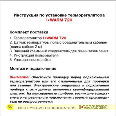
Важно! На неисправности прибора, возникшие вследствие механического повреждения, неправильного монтажа или эксплуатации в целях и условиях, не предусмотренных инструкцией по установке и эксплуатации прибора, гарантия производителя не распространяется.
Инструкция по установке и схема подключения не заменяет профессиональной подготовки монтажника прибора.
Мы рекомендуем при монтаже терморегулятора i warm 720 и системы обогрева воспользоваться услугами квалифицированных специалистов. Электрические соединения и подключение прибора к сети должен выполнять квалифицированный электрик.
Обесточьте проводку перед подключением терморегулятора или его отключением для тестирования.
Введение
Поздравляем Вас с приобретением новой интеллектуальной системы управления обогревом i warm 720. Компания ССТ рада предложить Вам новый подход в управлении системами электрического обогрева. Ваш новый терморегулятор подарит Вам легкость управления,


Автор: Admin · Опубликовано 08.10.2017 · Обновлено 05.12.2017
i warm 720 инструкция
Внимание! перед началом использования внимательно ознакомьтесь с данной инструкцией. Важно! На неисправности прибора, возникшие вследствие механического повреждения, неправильного монтажа или эксплуатации в целях и условиях, не предусмотренных инструкцией по установке и эксплуатации прибора, гарантия производителя не распространяется.
Инструкция по установке и схема подключения не заменяет профессиональной подготовки монтажника прибора.
Мы рекомендуем при монтаже терморегулятора i warm 720 и системы обогрева воспользоваться услугами квалифицированных специалистов. Электрические соединения и подключение прибора к сети должен выполнять квалифицированный электрик.
Обесточьте проводку перед подключением терморегулятора или его отключением для тестирования.
Введение
Поздравляем Вас с приобретением новой интеллектуальной системы управления обогревом i warm 720. Компания ССТ рада предложить Вам новый подход в управлении системами электрического обогрева. Ваш новый терморегулятор подарит Вам легкость управления,
Мы являемся официальными дилерами продукции:
8 (495) 585-72-79
8 (925) 585-72-79
Без выходных с 9:00 до 21:00 ч.

Терморегулятор Теплолюкс в подарок!
При заказе комплектов теплых полов Теплолюкс — терморегулятор.
Летние скидки на полы Теплолюкс
Сезон скидок на комплекты теплых полов Теплолюкс. Предложение ограничено.
Терморегуляторы по сниженным ценам
На линейку терморегуляторов Теплолюкс действуют специальные цены.
Теплолюкс — акция «Май побеждает…
Скидки до 30% на всю линейку товаров. Предложение.
Зимние скидки в Теплолюкс-Макси!

Уважаемые посетители, в нашем интернет-магазине действуют скидки на.
Новогодняя распродажа 2017

В период с 15 декабря по 14 января.
Подогрев грунта и обогрев теплиц

Система подогрева грунта и обогрева теплиц Green Box.
Весна — пора скидок!
Весной дарим скидку 25%
Теплолюкс Profi в продаже!

В продаже появилась новая линейка теплых полов Теплолюкс.
Осенние скидки
На все комплекты теплых полов в октябре действуют.
Продажа системы защиты от протечек

В продаже новые комплекты системы защиты от протечек.
Инструкция по монтажу терморегулятора I-Warm 720

| Каталог товаров | Полезная информация | Покупателю | Компания |
|---|---|---|---|
| Теплые полы Теплолюкс | Сертификаты | Как купить? | О магазине |
| Теплые полы IWARM | Видеоролики | Оплата | Новости |
| Терморегуляторы | Инструкции по монтажу | Доставка | Отзывы |
| Полотенцесушители | Информация о теплых полах | Акции и скидки | Контакты |
| Гарантия | |||
| Системы защиты от протечек воды | Помощь |
© 2007-2019 «Teplolux-MAXI» Официальный дилер Теплолюкс, Devi, Nexans, Thermo и Raychem.
Телефон: 8(495) 585-72-79
Часы работы: с 9.00 до 21.00 без выходных
E-mail: Этот адрес электронной почты защищен от спам-ботов. У вас должен быть включен JavaScript для просмотра.
- Manuals
- Brands
- I WARM Manuals
- Thermostat
- 710
- User and installation manual
-
Contents
-
Table of Contents
-
Bookmarks
Quick Links
T H E R M O S T A T
and installation
and installation
and installation
User
User
User
manual
manual
manual
Related Manuals for I WARM 710
Summary of Contents for I WARM 710
-
Page 1
T H E R M O S T A T User User User and installation and installation and installation manual manual manual… -
Page 2: Table Of Contents
Table of content: Introduction ……..3 Basic functions .
-
Page 3: Introduction
I•WARM thermostat you enter into the world of heating comfort, coziness and user friendliness. The I•WARM 710 device opens a new series of SST room thermostats which feature high reliability, easy adjustment, simple display, and modern design. Our intention is to make your home heating extremely comfort- able, cozy, simple and energy efficient.
-
Page 4: Basic Functions
Basic functions I•WARM 710 thermostat is designed for electrical underfloor heating systems (heating mats or sections). The device automatically keeps the temperature you have set based on data received from the floor mounted tempera- ture sensors (included in the delivery set). Both real floor temperature and the desired value you have preset are dis- played.
-
Page 5
Important: Don’t turn the newly built heating system on be fo re the tile fixing mixture or cement-sand mortar layer are harde ned. You can get the different hardening times from the manufacturer of your chosen building material. Turning on the heating system prematurely can lead to dam- age of the floor decorative cover and heating mats, or sections outage. -
Page 6
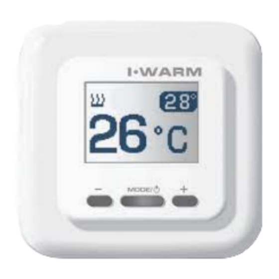
A lighted LCD display with three control buttons are locat- ed on the front panel of the thermostat. To turn the thermostat on/off press the center button /MODE) and hold it for not less than three seconds. Fig.2 Indication mode… -
Page 7: Controls And Display
The LCD display lights up and the basic screen appears. Large figures show the current floor temperature and the figures in the upper right corner show the preset floor temperature. You can change the preset temperature by pressing the «+» button to increase it and the «-» button to decrease it. Controls and display 1.
-
Page 8: Air Temperature Display Mode
Air temperature display mode The thermostat can display ambient temperature in your room instead of floor temperature. At that setting the device continues to control heating regardless of the display mode. heating system is powered symbol indication of actual room temperature actual room temperature Fig.3 Service indication in base mode…
-
Page 9: Adjustment Of Built-In Ambient Temperature Sensor Indicator
To switch the thermostat to ambient temperature display mode you should briefly press the center button ( /MODE). Large figures now display ambient temperature, and a sign (fig.3) appears, informing you that the device is switched to this mode. To return to floor temperature indication mode, press /MODE button once more.
-
Page 10
For adjustment of built in temperature sensor indication you should: appropriate data shift built in sensor current ambient temperature (flashing) Fig.4 Built-in ambient temperature sensor indicator 1. Switch the device to ambient temperature indication mode if another mode was used. -
Page 11: Control Of Heating System Operating Conditions
2. Press the «+» and the «-» buttons simultaneously and hold them for not less than 3 seconds. A large figure showing current ambient temperature will flash and a sign (fig.4) appears indicating sensor adjustment mode. Pressing the «+» and the «-» buttons set the indicated cur- rent temperature equal to the temperature shown by your room air thermometer.
-
Page 12
Fig.5 Indication of control mode of heating system thermostat permanently controls operability of the tem perature sensor. In case of a malfunction (cut-off or short-circuiting of connecting wires) during which normal operation of the heating system is impossible, the thermostat turns the heating off and displays a warning message (fig.5). -
Page 13: Manual Heating Control Mode
symbol indicating manual control mode percent of installed power being consumed Fig.6 Indication of manual heating control mode Manual heating control mode (Emergency mode) In case of temperature sensor outage the thermostat turns heating off. If heating of the room is still required it is possible to control heating manually for a time period until the sensor function is restored.
-
Page 14
When the sign (fig.6), which indicates the control mode, appears, the large figures show the average percentage of installed power being consumed by the heating system. You can adjust this percentage by pressing the «+» or the «-» buttons. The changes you make are reflected in the dis- played value. -
Page 15: Warranty Policy
Warranty policy Warranty period – one year from the date of sale. During the warranty period the customer has the right of repairing or replacement of the product due to faulty materials from the manufacturer on the condition that the manual guides to Installation and Operation of this device have been followed.
-
Page 16: Appendix
Appendix Delivery set I•WARM 710 Thermostat 2. Floor mounted temperature sensor with connection cable (2 m long). 3. External terminal block for grounding line connection 4. User and installation manual 5. Packing box Installation manual I•WARM Important: Switch off power before connecting or disconnect- ing wiring to the thermostat.
-
Page 17
be installed in a neighbouring “dry room”. Please study this manual carefully before starting the installation. Tools and materials required for thermostat installation: 1. Corrugated plastic tube not less than 16mm in diame- ter; the length depends on the distance between the thermo- stat and the heating unit. -
Page 18
Place the tube in a preprepared groove in the floor and lead its other end to the place chosen for thermostat or junction box. Cut off excess tube length. Fig.8 Installation of floor temperature sensor. -
Page 19
Installation of the thermostat Preparation of electrical connections. Install the plastic junction box into the wall where the loca- tion of the thermostat is planned. Lead the power supply cable, the cold leads of the heating mat or section, and the temperature sensor cable, into the box. -
Page 20
Network earthing External conductor terminal block Sensor of temperature 230-240VAC Single conductor heating cable Network earthing External conductor terminal block Sensor of temperature 230-240VAC Double conductor heating cable Fig.9 Thermostat connection diagram three wire power network… -
Page 21
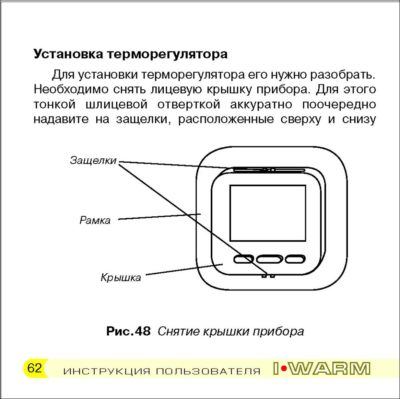
Installation of the thermostat First of all disassemble the thermostat. Take off the front cover, using a thin screwdriver, carefully press in the locks located on the upper and lower sides of the front cover, pulling it out slightly (fig. 10). Remove the cover (fig.11). Remove the frame (fig.12). -
Page 22
Screwdriver Frame Cover Fig.10 Open the thermostat cover… -
Page 23
Thermostat without cover Cover Thermostat Fig.11 The device with cover removed. The frame is shown by pointer. -
Page 24
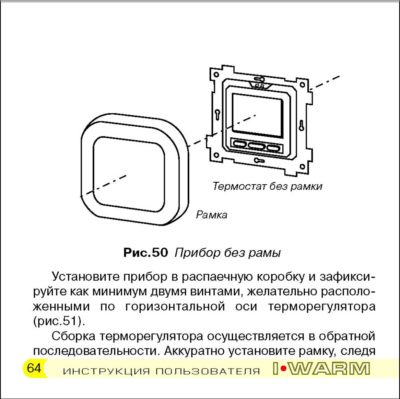
Thermostat without frame Frame Fig.12 Thermostat without frame… -
Page 25
Fig.13 The thermostat mounted into the wall and fastened by two screws located horizontally. -
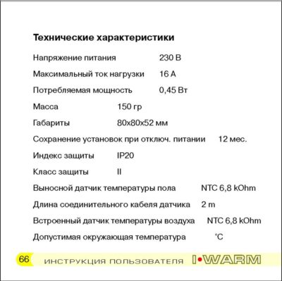
Page 26: Technical Specifications
Technical specification Supply voltage ……230 VAC ~50 Hz Maximum load current ……16А Consuming power .
-
Page 27
Allowable relative air humidity ……….80 % Maintaining temperature range ….from +5 °С to +45 °C, factory preset …………..+25 °C In the event of a queston, please refer to your local service center:…
ИНДИВИДУАЛЬНЫЙ ПОДХОД К КАЖДОМУ
- Бытовая техника
- Запчасти и аксессуары для бытовой техники
- Запасти и аксессуары — Машинки для стрижки волос
- Запасти и аксессуары — Аэрогриль
- Запасти и аксессуары — Блендеры
- Запасти и аксессуары — Отпариватели
- Запасти и аксессуары — Пылесос
- Запасти и аксессуары — Чайники
- Запасти и аксессуары — Электробритвы
- Запчасти и аксессуары — Паровая швабра
- Запчасти и аксессуары для бытовой техники
- Инструменты и расходные материалы
- Отвертки
- Рулетки
- Радиодетали (электронные компоненты)
- Электродвигатели, микромоторы
- Цифровая техника
- Запчасти и аксессуары для ноутбуков
- Запчасти и аксессуары для телефонов
- Запчасти и аксессуары для электронных книг
- Распродажа
Cart


Latest News
Рейтинговые товары
Products
Свежие комментарии
Нет комментариев для просмотра.

| Пн | Вт | Ср | Чт | Пт | Сб | Вс |
|---|---|---|---|---|---|---|
| 1 | 2 | |||||
| 3 | 4 | 5 | 6 | 7 | 8 | 9 |
| 10 | 11 | 12 | 13 | 14 | 15 | 16 |
| 17 | 18 | 19 | 20 | 21 | 22 | 23 |
| 24 | 25 | 26 | 27 | 28 | 29 | 30 |
| 31 |