-
Contents
-
Table of Contents
-
Bookmarks
Quick Links
0 — 12
Infusomat® Space
Service Manual
Version 6.0 English
RX only
0 —
Related Manuals for Braun Infusomat Space
Summary of Contents for Braun Infusomat Space
-
Page 1
0 — 12 Infusomat® Space Service Manual Version 6.0 English RX only… -
Page 2
This Service Manual is valid for Designation Part No. Infusion Pump Infusomat® Space ….0871 3050 Infusion Pump Infusomat® Space (USA)..0871 3050U Infusion Pump Infusomat®… -
Page 3: Table Of Contents
Table of Contents Important Preliminary Remarks Service Work Page 0 — 5 Technical Safety Checks Page 0 — 5 Current Versions Page 0 — 5 Product availability Page 0 — 5 Responsibility of the Manufacturer Page 0 — 6 Quality Management Page 0 — 6 Checks and Repair…
-
Page 4
Table of Contents Processor PCB Page 3 — 37 Installation / Assembly Page 3 — 40 Pole Clamp SP Adapter Kit Page 3 — 54 Checks after Repair Page 3 — 55 Servicing the Unit Cleaning and Disinfecting Page 4 — 1 Servicing the Battery Page 4 — 3… -
Page 5: Important Preliminary Remarks
Current Versions This manual version corresponds to the state when the manual was written. B Braun reserves the right to make technical modifi- cations. The state of the revision is indicated by the index number in the footer of every page.
-
Page 6: Responsibility Of The Manufacturer
B. Braun unit. Quality Management B. Braun is certified in accordance with DIN EN ISO 9001 and ISO 13485. This certification also includes maintenance and serv- ice. The unit has the CE label. The CE label confirms that the device corresponds to the “Directive of the Council for Medical Products…
-
Page 7: Spare Parts And Test Equipment
You can request the material safety data sheets for the consum- ables described in this Service Manual free of charge from B. Braun. You can download the latest version of each document as a PDF in the service portal under https://extranet.bbraun.com.
-
Page 8: Special Pdf Functions
Important Preliminary Remarks References to chapters are shown as follows (see „Setting Off“ ➨ pg. 0 — 7) References to figures and tables are shown as follows Fig.: 2 — 3 Table 2 — 1 References to item numbers in figures are shown as follows (Fig.: 1 — 1 / Item In this case “Fig.: 1 — 1“…
-
Page 9: List Of Abbreviations
Important Preliminary Remarks Deletion of non-applicable test steps by marking the en- try with the mouse and selecting “Strikethrough Text” in the shortcut menu (right mouse key; only for editing in the local form copy). File > Print Printing the completed form with and then selecting a connected printer.
-
Page 10
Important Preliminary Remarks Patient-Controlled Analgesia Perfusor® Space Space (System) SpaceCover SPCC SpaceCover comfort SPCS SpaceCover standard SPCO SpaceCom SPCT SpaceControl SpaceStation TEMP Temperature Technical Safety Checks Verband der Elektrotechnik, Elektronik und Informationstechnik e.V. (German electrical engineering association) 0 — 10 Infusomat®… -
Page 11: Contact Persons
Via local representative. Entry for Technical Training Application for a technical training course must be made via the responsible representative. Ordering of Spare Parts and Test Equipment Please contact your local B. Braun subsidary. International Technicians (Intercompany) e-mail: Spare-Parts_HC@bbraun.com Service Hotline Service Hotline International (without U.S.
-
Page 12
Contact Persons For your notes: 0 — 12 Infusomat® Space 6.0… -
Page 13: System Overview
1 — 18 System Overview Description The Infusomat® Space (ISPS) is according to IEC/EN 60601-1 or IEC/EN 60601-2-24 a portable volumetric infusion pump for infu- sion of small to high volumes with ultimate precision and is suit- able for intravenous applications, blood transfusion and enteral nutrition.
-
Page 14: Physical Construction
System Overview Physical Construction The Infusomat® Space housing mainly consists of the bottom part, the upper part, the front part and the operating device. The battery module is inserted in the rear of the housing upper part. The opening is covered by the battery compartment cover. The operating unit is attached to the front of the bottom part.
-
Page 15
System Overview Fig.: 1 — 2 Infusomat® Space Legend of fig. 1 — 2: Item Designation Infusomat® Space Connector “P2“ for SpaceStation module, external 12 V DC and accessories Operating unit Connector “P3“, connection to SpaceControl module Cover for drop sensor connector Battery compartment cover Infusomat®… -
Page 16: Function
System Overview Function There are two power options for the Infusomat® Space: Via the inserted battery module Via an external 12 V DC power supply (e.g. SpaceStation, SpaceControl, an external power supply or from an ambu- lance car) connected to connector “P2” The voltage supplied is converted to the internal voltages required through a voltage transforming and monitoring circuit on the processor PCB.
-
Page 17
System Overview The safety clamp squeezes the Infusomat® Space Line when the operating unit is opened or internal calibration is carried out to protect the patient and prevent an uncontrolled drug flow to the patient. Beside the position monitoring via the lock bolt, the “open/closed”… -
Page 18
System Overview Opening the Operating Unit Manually 1. Press the locking of the battery compartment cover using a pointed tool and remove the battery compartment cover from the housing. 2. Remove the emergency release crank out of the battery com- partment cover. -
Page 19
System Overview 4. Turn the emergency release plug carefully with the emergen- cy release crank through 90° to the right (clockwise in arrow direction) until stop and remove the plug out of the housing. 5. Insert the emergency release crank in the housing opening. The crank must be pushed in the hexagon socket of the lock bolt drive. -
Page 20
System Overview Fig.: 1 — 7 Block Diagram Infusomat® Space 1 — 8 Infusomat® Space 6.0… -
Page 21: Unit Software
686L033001 (for China only) Modified alerting 686M03000X Improved functions 586U030003 (for US only) * Not all software versions, hardware, or spare parts are available in all regions. Please consult your local B. Braun representative for availability. Infusomat® Space 6.0 1 — 9…
-
Page 22: Service Program
PC is switched off during a software update. If this happens, it may no longer be possible to carry out the software update via the PC and the device will have to be sent to B. Braun. Service Program Approved Versions…
-
Page 23
System Overview 1. Start the “HiBaSeD.exe“ program (History, Barcode, Service, Drug list) on the PC. The Service Program is loaded and start- ed and the initial window of the Service Program is displayed. 2. Read the notes carefully. 3. Mark the field “I accept all conditions” and then the field “Yes”… -
Page 24
System Overview Fig.: 1 — 11 5. Activate the desired device from the list on the left in the work window with a double-click. The device data is then dis- played below the device name. 1 — 12 Infusomat® Space 6.0… -
Page 25
System Overview If the unit software version is not compatible with the Service Program version, a window opens prompting the operator to change the Service Program version. This window displays a compatibility list of the Service Program- and unit software versions. -
Page 26
System Overview Fig.: 1 — 15 Service Program Version Help Info … 1. Open the “HiBaSeD“ window via ➨ . The current version of the Service Program is shown in this window. 2. Close the window by clicking “OK”. Fig.: 1 — 16 1 — 14 Infusomat®… -
Page 27
System Overview Compatibility List Help Compat- 1. Open the “Unit — Compatibility“ window via ➨ ibility . This window displays the compatibility of the Hi- BaSeD-version and the unit software version. 2. Close the window by clicking “OK”. Fig.: 1 — 17 Quitting the Service Program File Exit… -
Page 28: Technical Data
System Overview Technical Data All technical data is indicated in the Instructions for Use. Options The functions of the individual options are detailed in the Instruc- tions for Use. Infusomat® Space Designation Part No. Power supply Euro ….. . 0871 3110A/B/C/D Power supply UK .
-
Page 29: Functional Test Acc. To §5, Section 1, Mpbetreibv (German Medical Devices Operator Ordinance)
(date). Infusomat® Space has been handed out without any damage and in proper working order. Date Signature B. Braun Signature Hospital * Mandatory in some countries in which medical product laws apply, and strongly recommended in all other countries. Infusomat® Space 6.0…
-
Page 30
System Overview For your notes: 1 — 18 Infusomat® Space 6.0… -
Page 31: Unit Diagnosis / Calibration
2 — 16 Unit Diagnosis / Calibration Alarms and Error Codes The alarms of the Infusomat® Space are classified in 5 categories. These categories are listed hereafter according to their impor- tance. Alarm advice In case of unacceptable inputs corresponding messages are displayed (e.g.
-
Page 32
Unit Diagnosis / Calibration Alarms Alarm Possible Cause Fault Clearance Battery nearly discharged (type: pre- The device was not connected to the Connect device to the supply voltage via alarm) mains long enough the AC adaptor plug. Start battery maintenance by pressing “OK”, if this message is displayed when the device is switched off. -
Page 33
Restart the device, change settings gether with special settings slightly if necessary. If the error persists: Please load the history file via HiBaSeD and inform B. Braun 2088 … 2090 Internal error Table 2 — 2 Error Codes of the Function Processor Infusomat®… -
Page 34
Restart the device, change settings together with special settings slightly if necessary. If the error per- sists: Please load the history file via HiBaSeD and inform B. Braun 2170 … 2173 DLOCK Error Error in relation to Datalock to- Restart the device, change settings gether with special settings slightly if necessary. -
Page 35
DIFF Error tion together with special set- slightly if necessary. If the error per- tings sists: Please load the history file via HiBaSeD and inform B. Braun 2199 … 2200 Internal Error 2201 different version FuP to KuP Software Update unit software… -
Page 36
Restart the device, change settings together with special settings slightly if necessary. If the error per- sists: Please load the history file via HiBaSeD and inform B. Braun 2290 … 2301 Internal error 2320 … 2328 RTM error Error in relation to Ramp and… -
Page 37: Can Error States
Unit Diagnosis / Calibration CAN error states Signalling of a CAN error In case of SW F, a faulty CAN bus is signalled by the blue LED at the pump flashing. The LED flashes at the following speeds: 300 ms on, 300 ms off 100 ms on, 100 ms off 100 ms on, 100 ms off The process is then repeated.
-
Page 38
Unit Diagnosis / Calibration Locating/eliminating communication problems If communication problems arise during operation of the pump in the SpaceStation, the blue LED on the pump will flash. If all pumps flash blue, this means that they are no longer communicating via CAN and are therefore not communicating with the SpaceCover either. -
Page 39
Unit Diagnosis / Calibration c) If the fault does not occur with the first two pumps, test the other pumps affected by the communication problem on the same slot until you have found the defective pump. Eliminating the CAN-Dead state 1. -
Page 40: The Most Important Error Modes
Unit Diagnosis / Calibration The Most Important Error Modes The following list specifies the most important error modes and their clearance. Error/Fault Possible Cause Fault Clearance The battery module discharges too fast The device has not been used for some ❒…
-
Page 41
Unit Diagnosis / Calibration Note Please note that text and / or functions of the Service Program may change depending on the software version. The following screenshots are only examples and represent the state when the manual was printed. 1. Start the Service Program (see „Starting the Service Program“… -
Page 42
Unit Diagnosis / Calibration 4. If requested by the device, enter the date and time. 5. Select a language from the list in the device and confirm your selection by using the «OK» key on the device. The «Worker ID» window opens. -
Page 43
Unit Diagnosis / Calibration 8. If HiBaSeD could not clearly read the device type, you are prompted to select a type. Select the device type by clicking the flag with the mouse. Note The device type can be specified via the article number. This article number is indicated on the rating plate. -
Page 44
Unit Diagnosis / Calibration Fig.: 2 — 7 11. Start calibration with the “OK“ button. You are prompted to press the blue connection key on the device. 12. Press the blue connection key. All device data are read out and stored in the PC. Fig.: 2 — 8 2 — 14 Infusomat®… -
Page 45
Unit Diagnosis / Calibration 13. If the safety clamp (locking clamp or clamping lever ) open, you are requested to close the safety clamp. Close the safety clamp with the slide clamp. The “Lock bolt calibration” group box is now activated. The lock bolt is moved into the open position. -
Page 46
Unit Diagnosis / Calibration 20. At the end of calibration the result with all the values is dis- played in the “Calibration process completed successfully” group box and the data are stored in the unit. This report can be printed out by pressing the “Print” button. Fig.: 2 — 13 21. -
Page 47: General
3 — 58 Disassembly / Assembly 3.1 General Remarks on Disassembly / Assembly Before each disassembly and assembly of a unit subsystem check the connectors, plug contacts and connections for corrosion and tight fit. The necessary steps to disassemble the complete unit, all its sub- systems and spare parts are detailed in the following description.
-
Page 48
Disassembly / Assembly Preparations for Exchanging the Processor PCB If the processor PCB is to be replaced, a back-up of the pump set- tings is to be carried out, if this is still possible. Note Please note that text and / or functions of the Service Program may change depending on the software version. -
Page 49
Disassembly / Assembly Fig.: 3 — 2 4. Select the tab “IO“ and actuate the “To device“ button. In the window that now opens you are asked for the storage position of the file on the PC hard disk and the file name. Note The suggested storage position should not be changed. -
Page 50
Disassembly / Assembly 5. Enter a unique file name. 6. Press the «Save» command button. The data of the pump are stored on the hard disk of the PC. Fig.: 3 — 3 7. Activate the «Print» command button in order to send the data of the device to a printer as required. -
Page 51
Disassembly / Assembly 8. Select the tab “Disposable article”. Fig.: 3 — 5 9. Press the “From device“ button. The data are read from the device. The data of the disposable articles are displayed on screen. Infusomat® Space 6.0 3 — 5… -
Page 52
Disassembly / Assembly Fig.: 3 — 6 10. Press the “Save as“ button. In the window that now opens you are asked for the storage position of the file on the PC hard disk and the file name. 11. In the “Save file as” window, select the storage position and enter a unique file name. -
Page 53
Disassembly / Assembly Note Once the new processor PCB has been installed, the saved data must be transferred back to the device (see „Processor PCB“ ➨ pg. 3 — 41). Service Parts and Screw Kit All small parts, such as cover caps, are contained in an Infusomat® Space service part kit. -
Page 54
Disassembly / Assembly Designation Order No. Grease for Infusomat® Space Polylub GLY 501 ..3452 1570 Housing foot SP (20 pieces) ….. 3477 3106 Space sticker set. -
Page 55: Slide Guide
Disassembly / Assembly 3.2 Slide Guide Designation Order No. Slide guide ISPS, compl……3452 1330 Slide guide ISPS, compl….. . . 3452 1330U (temperature in Fahrenheit) Disassembly 1.
-
Page 56: Cover For Drop Sensor Connector
Disassembly / Assembly 3.3 Cover for Drop Sensor Connector Designation Order No. Cover, drop sensor connector ….3452 1577 Disassembly 1. Carefully remove the cover (Fig.: 3 — 9 / Item 1) for the drop sensor connector from the rear to the front and out of the…
-
Page 57: Unit Foot
Disassembly / Assembly 3.5 Unit Foot Designation Order No. Unit foot ……..3477 3106 (see „Service Parts and Screw Kit“…
-
Page 58: Battery Module
Disassembly / Assembly 3.6 Battery Module Designation Order No. Battery compartment cover ISP, cpl….3452 1321 (incl. emergency release crank) Battery module SP (NIMH), without fixing pin ..3452 0856 Battery module SP (NIMH), with fixing pin .
-
Page 59
Disassembly / Assembly 2. Lift the lock (Fig.: 3 — 13 / Item 3) on the battery module (Fig.: 3 — 13 / Item 1) and remove the battery module from the device. Fig.: 3 — 13 Legend of fig. 3 — 13: Item Designation Battery module Battery compartment cover… -
Page 60
Disassembly / Assembly Conversion, Retrofitting kits, and Spare Part Battery Contact Strip Designation Order No. Retrofitting kit battery fastening ….3452 1365 sufficient for 10 devices free delivery Spare part battery contact strip . -
Page 61
Disassembly / Assembly The following hardware versions of the battery module and of the battery contact strip exist: Old Version New Version Battery contact strip, without fixing hole Battery contact strip with fixing hole Battery module without fixing pin Battery module with fixing pin Top housing section, right, without fastening ribs Top housing section, right, with fastening ribs Top housing section, left, without fastening ribs… -
Page 62
Disassembly / Assembly The following combinations are not compatible: Battery module with fixing pin and battery contact strip without fixing hole Top housing section with fastening ribs and additional bond- ing segments Bonding segments in connection with a battery with fixing pin and a battery contact strip with fixing hole Retrofitting of the battery fastening Note… -
Page 63
Disassembly / Assembly 2. In order to retrofit the top housing section, clean the bonding areas (Fig.: 3 — 15 / Item 1) with isopropanol and let them air. Fig.: 3 — 15 Legend of fig. 3 — 15: Item Designation Bonding areas 3. -
Page 64
Disassembly / Assembly 6. If the retrofitting kit is used, replace the battery slide on the battery module (nominal dimension after replacement: 2.15 mm ±0.15 mm). 7. Clean the bonding areas with isopropanol and let them air. 8. Position the removal aid (Fig.: 3 — 17 / Item 1) over the fixa- tion… -
Page 65: Housing Upper Part
Disassembly / Assembly 3.7 Housing Upper Part Designation Order No. Housing upper part ISP ……3452 1313 Screws and cover caps (see „Service Parts and Screw Kit“…
-
Page 66
Disassembly / Assembly 3. Loosen the snap-on mechanism of the housing upper part (Fig.: 3 — 19 / Item 1) carefully. To do so, a screwdriver can be inserted in the two openings between the housing front panel and the housing top. Note It is also possible to remove the housing upper part by gripping into the battery compartment and tilting the upper part forward. -
Page 67
Disassembly / Assembly 5. Unscrew two screws and remove the contact strip (Fig.: 3 — 20 / Item 3) to the battery compartment together with the connection cable out of the housing upper part (Fig.: 3 — 20 / Item Note If necessary, the spring-mounted contact pins must be carefully pressed in when the contact strip is removed. -
Page 68: Housing Bottom Part
Disassembly / Assembly 3.8 Housing Bottom Part Designation Order No. Loudspeaker SP ……. 3452 0937 Housing bottom part ISP .
-
Page 69: Inner Frame And Housing Front Panel
Disassembly / Assembly 3.9 Inner Frame and Housing Front Panel Designation Order No. Screws (see „Service Parts and Screw Kit“ ➨ pg. 3 — 7) Note Please pay attention to the corresponding notes during assembly and installation (see „Inner Frame and Housing Front Panel“ ➨ pg.
-
Page 70
Disassembly / Assembly 4. Loosen four screws (Fig.: 3 — 23 / Item 2)and lift the inner frame together with the housing front panel from the bottom inner frame(Fig.: 3 — 23 / Item 5. Unscrew one screw (Fig.: 3 — 23 / Item 5) and remove the PCB of the direction of rotation sensor for the pump drive from the pump frame. -
Page 71: Inner Frame
Disassembly / Assembly 3.10 Inner frame Designation Order No. Lock bolt drive ISP ……3452 1429 Linear poti ISP .
-
Page 72
Disassembly / Assembly Fig.: 3 — 24 Legend of fig. 3 — 24: Item Designation Lock bolt Bracket Countersunk screw M3x5 TORX Pressure adjustment unit Inner frame Pump frame Lock bolt drive Guide (6 mm straight pin) Linear potentiometer with cable loom 10 Bracket locking 3 — 26 Infusomat®… -
Page 73: Fig
Disassembly / Assembly 4. Unscrew one screw (Fig.: 3 — 25 / Item 1), turn the pump drive motor (Fig.: 3 — 25 / Item 2) clockwise out of the holder and remove it from the pump frame. 5. Move the lock bolt drive by hand in the middle position. 6.
-
Page 74
Disassembly / Assembly WARNING Injuries through hot soldering iron tip and development of dan- gerous vapours! RISK OF INJURY AND POISONING! Have soldering work carried out only by trained and author- ised persons and in suitable premises. 9. Unsolder the two connection leads (Fig.: 3 — 26 / Item 2) at the pump drive motor… -
Page 75: Housing Front Panel
Disassembly / Assembly 3.11 Housing Front Panel Designation Order No. Membrane ISP ……. . 3452 1356 Pressure sensor ISP .
-
Page 76
Disassembly / Assembly Disassembly 1. Press the membrane out of the housing front panel. 2. Unscrew two screws and remove the pressure sensor, up- stream from the housing front panel. 3. Unscrew two screws and remove the pressure sensor, down- stream from the housing front panel. -
Page 77: Operating Unit
Disassembly / Assembly 3.12 Operating Unit Designation Order No. Operating unit ISPS, cpl……3452 1470 Operating unit ISPS, cpl., US ….3452 1470U LC display SP .
-
Page 78
Disassembly / Assembly 3. Unscrew 6 screws (Fig.: 3 — 30 / Item 1) and remove the seal washers (Fig.: 3 — 30 / Item 2) from the operating unit rear panel (metal front sheet, Outsert, Version II) (Fig.: 3 — 30 / Item Note The screws of the keyboard must not be loosened. -
Page 79
Disassembly / Assembly 5. Open the connector lock (Fig.: 3 — 31 / Item 2) on the key- board PCB. 6. Pull the LC display ribbon cable (Fig.: 3 — 31 / Item 1) out of the connector. Fig.: 3 — 31 Legend of fig. -
Page 80
Disassembly / Assembly 8. Pull the left (Fig.: 3 — 33 / Item 1) and right hinge cover (Fig.: 3 — 33 / Item 4) off the axle (Fig.: 3 — 33 / Item 9. Press the axle out of the operating unit rear panel (Fig.: 3 — 33 / Item 7), the bottom inner frame… -
Page 81
Disassembly / Assembly Repairing Metal Front Sheet, Outsert ISPS, Version II Designation Order No. Front flap sealing strip……On request 1. -
Page 82
Disassembly / Assembly 9. Press the sealing strip (Fig.: 3 — 36 / Item 1) down to the bot- tom using a spatula and bond it. 10. After bonding smoothen the sealing strip with the spatula. Fig.: 3 — 36 Legend of fig. -
Page 83
Disassembly / Assembly 3.13 Processor PCB Designation Order No. Processor PCB ISP ……3452 1348 (incl. -
Page 84
Disassembly / Assembly Mounting Connector Seal P2 (self-adhesive) Designation Order No. Connector seal P2 SP 3477 3102 1. Clean the adapter (Fig.: 3 — 39 / Item 1) of the connector seal P2 all round with isopropanol and let it air. Fig.: 3 — 39 Legend of fig. -
Page 85
Disassembly / Assembly 3. Slide the connector seal P2 (Fig.: 3 — 41 / Item 1) onto the connector enclosure using a scalpel. Fig.: 3 — 41 Legend of fig. 3 — 41: Item Designation Connector seal P2 In order to avoid bubbling press the connector seal P2 (Fig.: 3 — 42 / Item 1) on completely. -
Page 86
Disassembly / Assembly 3.14 Installation / Assembly Assembly or installation of the modules and subsystems is per- formed in reverse order of disassembly. Special steps to be ob- served are described hereafter in detail. Only new cover caps are to be used. Special Screws Special screws for plastic housings are used in this unit. -
Page 87
Disassembly / Assembly Processor PCB 1. The adjusting lug of the bottom inner frame must be posi- tioned in the processor PCB boring. When the processor PCB is replaced all data of the pump except for the calibration data was probably saved on a PC(see „Prepara- tions for Exchanging the Processor PCB“… -
Page 88: Inner Frame
Disassembly / Assembly Inner Frame Fig.: 3 — 44 Legend of fig. 3 — 44: Item Designation Lock bolt, plastic guides Inner frame, spring holder with pressure spring Bracket locking Pump frame, bearing of the 6 mm straight pin Pump drive, movement areas Pump drive, toothed wheels Lock bolt drive, toothed wheels Lock bolt, guides and supporting area…
-
Page 89: Lock Bolt Drive
Disassembly / Assembly 1. Make sure that the following components are sufficiently lu- bricated when installing the inner frame. If the grease film is not sufficient (stiff or jerky movements) grease these areas slightly with Polylub GLY 501. Note If chemical substances such as lubricating grease are used the safety data sheets are to be observed (see „Safety data sheets“…
-
Page 90
Disassembly / Assembly Inner Frame and Housing Front Panel 1. Move the lock bolt by hand to the left until stop (open posi- tion) before mounting the housing front panel. 2. Close the safety clamp with a slide clamp after installation. 3. -
Page 91
Disassembly / Assembly 6. During installation of the complete housing front panel on the bottom inner frame the positioning hemispheres (arrow, Fig.: 3 — 46) of the inner frame must be adjusted in the slots of the bottom inner frame. Fig.: 3 — 46 7. -
Page 92
Disassembly / Assembly Housing Upper Part 1. If you have carried out any activities on the pressure adjust- ment unit, or dismounted or replaced the pressure adjust- ment unit, remove the rectangular cover cap from the housing top and keep it in a safe place until calibration, be- fore mounting the housing upper part. -
Page 93
Disassembly / Assembly 1. Start the Service Program (see „Starting the Service Program“ ➨ pg. 1 — 10). 2. Select the tab “Modification data”. Fig.: 3 — 48 3. Press the “From file“ button. The window “Open” is displayed on screen. Infusomat®… -
Page 94
Disassembly / Assembly 4. Select the desired file with the mouse pointer and press the “Open” button. 5. On tab “IO”, press the “To device“ button. Fig.: 3 — 49 Fig.: 3 — 50 3 — 48 Infusomat® Space 6.0… -
Page 95
Disassembly / Assembly 6. Press the “OK“ button when the window “Confirmation“ is displayed. Fig.: 3 — 51 7. Enter your user number in the window “Worker ID” as well as the six-digit serial number of the device, if necessary. 8. -
Page 96
Disassembly / Assembly Fig.: 3 — 54 12. Press the “Load from“ button. The window “Open” is displayed on screen. 13. Select the desired file with the mouse pointer and press the “Open” button. The loaded data are displayed on screen. Fig.: 3 — 55 3 — 50 Infusomat®… -
Page 97
Disassembly / Assembly Fig.: 3 — 56 14. Press the “To device“ button. The data is saved in the Infuso- mat® Space. 15. Exit the Service Program (see „Quitting the Service Program“ ➨ pg. 1 — 15). Infusomat® Space 6.0 3 — 51… -
Page 98
“HiBaSeD 8.0.1_1_neue Schlauchdaten”. Fig.: 3 — 59 5. Delete all subdirectories under the following directory C:\B.Braun Space\HiBaSeD_8.0.1_1\dat\Infusomat. Fig.: 3 — 60 In the case ofInfusomat® Space serial numbers 271705 and higher, a new dispos- able article table for SW L has already been imported at the factory. -
Page 99
Disassembly / Assembly 6. Unpack the zip file with the new tube data (available on re- quest) into the following directory C:\B.Braun Space\HiBaSeD_8.0.1_1\dat\Infusomat. Alternatively: Copy the unpacked folders “default” and “Dis- posables” to that same directory. Fig.: 3 — 61 7. -
Page 100
Disassembly / Assembly 3.15 Pole Clamp SP Adapter Kit Designation Order No. Retrofit kit Pole Clamp ……3477 4390 contains: Grid right reworked (10 pieces) Grid left reworked (10 pieces) -
Page 101
Disassembly / Assembly 3.16 Checks after Repair Procedure 1. Remove a slide clamp which may be inserted in the safety clamp and open safety clamp (press and engage operating le- ver). 2. When the activities described in chapter 3.2 to 3.8 have been performed, a visual inspection and self test are necessary. -
Page 102
Disassembly / Assembly Check List for Checks after Repair Unit: Infusomat® Space Article No. Unit No. Manufacturer: B. Braun Melsungen AG Visual Inspection Electrical Safety Functional Inspection According to IEC 60601-1 or IEC 62353 ❒ Cleanliness, completeness, damage and The patient and housing leakage current of ❒… -
Page 103
Disassembly / Assembly Visual Inspection Electrical Safety Functional Inspection According to IEC 60601-1 or IEC 62353 Pressure switch-off, electronic: (see TSC for limit values) Delivery rate: 250 ml/h Testing without drop sensor Infusomat® Space Line, standard type ❒ Upstream ❒ Alarm ❒… -
Page 104
Disassembly / Assembly Visual Inspection Electrical Safety Functional Inspection According to IEC 60601-1 or IEC 62353 Air inline sensor (see TSC for limit values) Infusomat® Space Line, standard type ❒ Water value ❒ Difference of temperature sensors ❒ Air alarm ❒… -
Page 105
We recommend using the cleaning and disinfecting agents Meliseptol® Wipes sensitive or Meliseptol® Foam pure from B. Braun for cleaning and disinfecting. In the case of severe soiling that cannot be removed by the above method, please contact the hospital’s technical de- partment. -
Page 106
Servicing the Unit Internal tube routing areas The slide guide and the internal tube guides can be cleaned with disinfectants containing 1-propanol or didecyl dimenthyl ammo- nium chloride. The slide guide can be prised out with a pointed object (ballpoint pen) through a notch in the housing front panel on the right lower side (Fig.: 4 -… -
Page 107
Servicing the Unit Procedure: 1. Set the pump down with the rear facing upward; fix it in po- sition, if necessary. 2. Fill the connector with contact cleaner. Depending on the ex- tent of soiling, allow to work. 3. Loosen any incrustations with a cleaning brush. 4. -
Page 108
Servicing the Unit For your notes: 4 — 4 Infusomat® Space 6.0… -
Page 109
Checklist for Technical Safety Check – Every 24 Months User Unit: Infusion Pump Infusomat® Space Manufacturer: B. Braun Melsungen AG Observe the Service Manual and the instructions for use. All measured values are to be Year of Procurement documented. Accessories used should be included in testing. Make exclusive use of cali- brated measuring equipment. -
Page 110
Technical Safety Check (TSC) Index h (Master – to be added to the documentation) Visual Inspection Electrical Safety Functional Inspection According to IEC 60601-1 or IEC 62353 Operation (continued) ❒ Trigger bolus at the device ❒ Trigger bolus by pressing the PCA but- ❒… -
Page 111
Technical Safety Check (TSC) Index h (Master – to be added to the documentation) Visual Inspection Electrical Safety Functional Inspection According to IEC 60601-1 or IEC 62353 Air inline sensor ❒ Water value (> 600 mV) ____ mV ❒ Difference of temperature sensors (<… -
Page 112
Checklist for Technical Safety Check – Every 24 Months User Unit: Power Supply SP Manufacturer: B. Braun Melsungen AG Observe the Service Manual and the instructions for use. All measured values are to be Year of Procurement documented. Accessories used should be included in testing. Make exclusive use of cali- brated measuring equipment. -
Page 113
6 — 10 Procedural Instructions on the TSC Visual Inspection Infusomat® Space 1. Check the Infusomat® Space and accessories for cleanness. 2. Check the Infusomat® Space and accessories for complete- ness and check configuration. 3. Check the Infusomat® Space and its accessories for damage and the labels for readability. -
Page 114
Procedural Instructions on the TSC Power Supply SP 1. Power supply SP incl. Check that the connecting line is clean. 2. Power supply SP incl. Check the connecting line for damage and the labels for readability. Electrical Safety Infusomat® Space According to IEC 60601-1 or IEC 62353 The patient and housing leakage current of the Infusomat®… -
Page 115
Procedural Instructions on the TSC Functional Inspection Infusomat® Space Mechanical Inspection 1. Fit the unit to be tested on top of another Space device and check the proper functioning of the lock. 2. Fit the unit to be tested under another Space device and check the proper functioning of the lock. -
Page 116
Procedural Instructions on the TSC 2. Battery check Perform the battery service to discharge the battery until the battery pre-alarm is issued (no bar displayed for battery dis- charge level (Fig.: 6 — 4), but it must not flash). Open and close the operating unit 5x. Replace the battery if the battery alarm sounds while you open or close the operating unit. -
Page 117
Procedural Instructions on the TSC d) Staff call — Plug service connector Space onto connector “P2”. — Lock roller clamp of Infusomat® Space Line. The red LED on the Space service connector lights up after an alarm is issued. e) Carry out infusion with intermediate bolus and press all buttons at least once. -
Page 118
Procedural Instructions on the TSC Test Setup Perform test setup with the subassemblies listed below, please see also Fig.: 6 — Note The filling level in the container must be approx. 50 cm above the middle of the unit opening for the Infusomat® Space Line. Infusomat®… -
Page 119
Procedural Instructions on the TSC 4. Vent test setup, position of the three-way cocks please see Fig.: 6 — 6, start infusion and deliver first of all in to an open system (without pressure gauge). Upstream 5. Push roller clamp of the Infusomat® Space Line up to approx. 30 cm before the pump and close the roller clamp or pinch the Infusomat®… -
Page 120
Procedural Instructions on the TSC Note If the pressure values are not reached, the mechanical pressure li- mit can be adjusted at the spring set of the peristaltic pump, see (Fig.: 3 — 24 / Item 4. Document values. Do not reduce pressure. Safety Clamp 1. -
Page 121
Procedural Instructions on the TSC Delivery rate determination: 1. Set a delivery rate of 200 ml/h and let device fill up ≥60 s. 2. Hang the outlet cannula over the container and at the same time start the stop watch and the Infusomat® Space. 3. -
Page 122
Procedural Instructions on the TSC 9. Generate an air bubble of approx. 0.4 ml (approx. 56 mm length of line with air) in the supply line to the pump. An alarm is triggered when the air bubble is detected. 10. Insert an air-filled Infusomat® Space Line into the device and close the operating unit, or disconnect the line at the con- tainer and “empty“, so that there is no longer any water in the line. -
Page 123
7 — 2 Test Equipment and Special Tools Test equipment Designation Order No. For Calibration Space service connector ……3452 1062 HiBaSeD Service-CD. -
Page 124
Test Equipment and Special Tools Special Tools Designation Order No. Screwdriver 6IPx60 TORX plus ….4002 4806 Screwdriver 8IPx60 TORX plus ….4002 4814 Screwdriver 10IPx80 TORX plus . -
Page 125
8 — 6 Spare Parts List Item Designation Ord. No. Service part kit Infusomat® Space … 3452 1593 contains: Housing cover cap (100 pieces) Plug D=4mm for front flap hinge (5 pieces) Cap for housing upper part (access to pressure adjust- ment) (2 pieces) Housing foot SP (10 pieces) -
Page 126
Spare Parts List Item Designation Ord. No. Screw kit Infusomat® Space ….3452 1585 contains: Screw DELTA PT 22×8 WN 5451 TORX plus 6IP (5 pieces) Screw DELTA PT 25×7 WN 5451 TORX plus 8IP (5 pieces) Screw DELTA PT 30×8 WN 5452 TORX plus 10IP (10 pieces) -
Page 127
Spare Parts List Item Designation Ord. No. Retrofit kit Pole Clamp ….. 3477 4390 contains: Grid right reworked (10 pieces) Grid left reworked (10 pieces) VDO compression spring (40 pieces) Straight pin 2×10 A2 (20 pieces) -
Page 128
0 — 6 Spare Parts List Spare Parts List 4, 5 12, 13 Fig.: 8 — 1 Exploded drawing Infusomat® Space 8 — 4 Infusomat® Space 6.0… -
Page 129
Spare Parts List Slide guide ISPS, compl….3452 1330 Slide guide ISPS, compl….3452 1330U (temperature in Fahrenheit) Cover, drop sensor connector . -
Page 130
Spare Parts List For your notes: 8 — 6 Infusomat® Space 6.0… -
Page 131
9 — 2 Revision Documentation Description of Version Version 1.0 (Base Version) First version of this Service Manual. Release date: 31.03.06 Version 1.1 AC adapters changed TSC of the AC adapters changed Spare part number of the ISP processor PCB changed Release date: 22.03.07 Version 2.0 Modified TSC of the Infusomat®… -
Page 132
Revision Documentation Version 4.0 Checklist for functional test prior to first use Revised error code lists New air inline sensor Revised instructions for cleaning and disinfection Changed TSC of the unit Revised procedural instructions on the TSC Version-specific Pole Clamp spare parts Changed general spare parts Version 5.0 Screenshot corrections… -
Page 133
10 — 2 Index 10 — Housing front panel ……3 — 23, 3 — 29 Accessories ……..1 — 16 Installation . -
Page 134
Index Service Program ……..1 — 10 Quit . -
Page 136
B. Braun Melsungen AG | Carl-Braun-Straße 1 | 34209 Melsungen | Germany Tel +49 (0) 5661 71-0 | Fax +49 (0) 5661 71-4567 | www.bbraun.de Mat. No. 8713 9120, Doc. No. M686_000671, Version 6.0…

Автоматизированная волюметрическая инфузионная система Инфузомат Спэйс B braun состоит из переносного электронного волюметрического насоса, специальных инфузионных систем и принадлежностей к насосу. Система предназначена для проведения терапии у взрослых, детей и новорожденных. Инфузомат Спэйс B braun предназначен для проведения периодического или непрерывного парентерального или энтерального введения растворов через клинически обусловленные доступы. Перечень доступов включает венозный, ирригационный/абляционный и энтеральный, но не ограничивается только ими.
Система Инфузомат Space B braun применяется для введения медикаментов, предназначенных для инфузионной терапии, включая коллоиды и кристаллоиды, кровь и ее компоненты, полное парентеральное питание, липиды, энтеральные смеси, но не ограничивается только ими. Автоматизированная волюметрическая инфузионная система Инфузомат Спэйс B braun предназначена для применения подготовленным медицинским персоналом в стационарных и амбулаторных лечебных учреждениях, на дому и в санитарном транспорте.
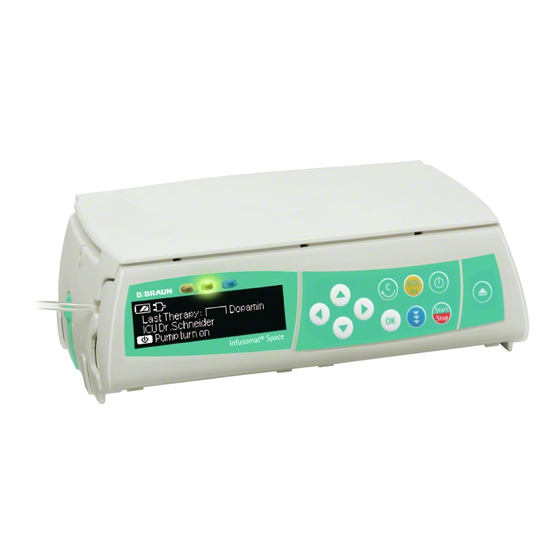
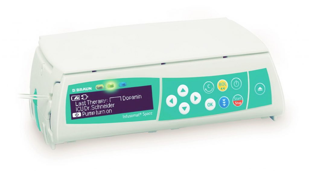
Инфузомат Спэйс B braun обзор
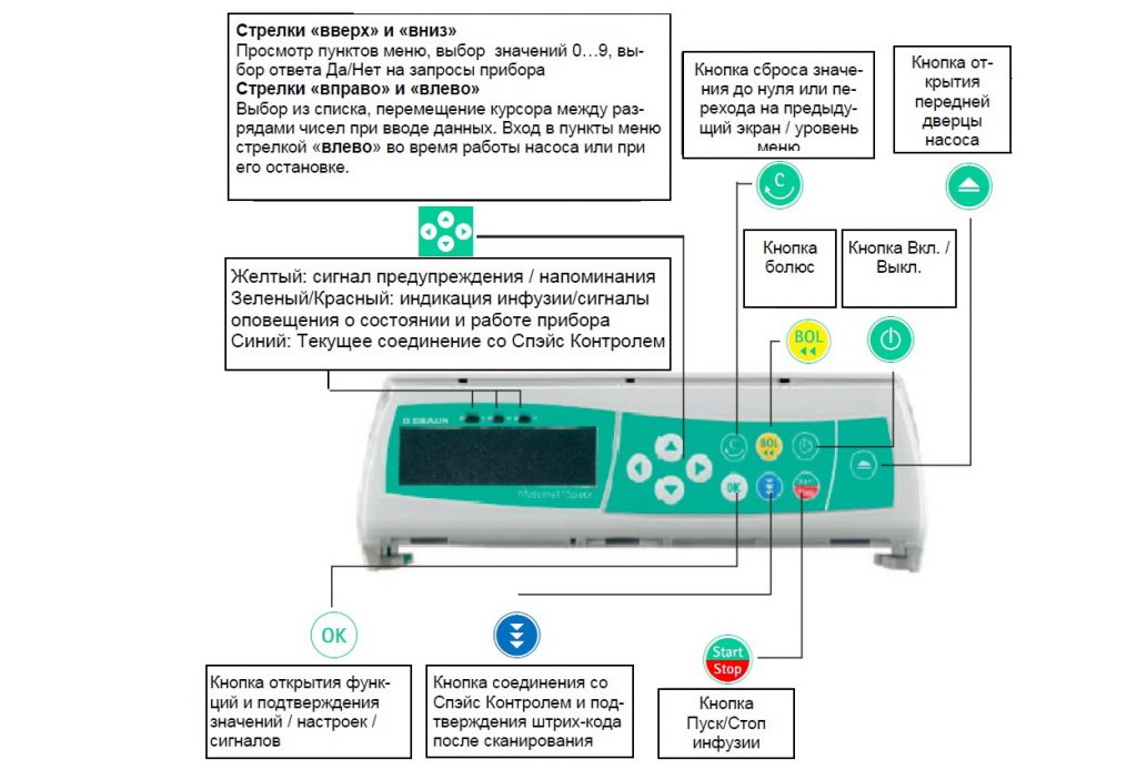
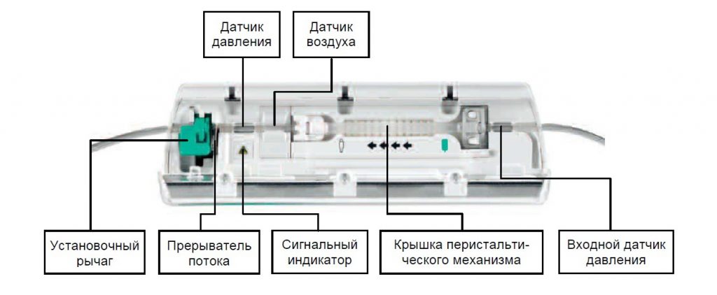
Передняя панель
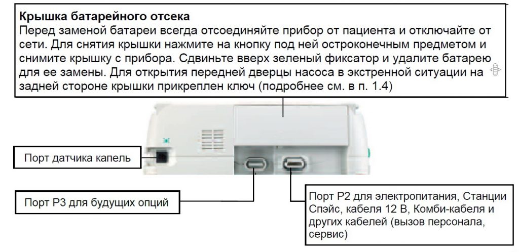
Вид сзади
Установка линии Инфузомат Спэйс B braun
Список лекарств Инфузомат Спэйс B braun
До 720 наименований лекарств, включая параметры инфузии и информацию о лекарстве, могут быть сохранены в 15 категориях. Загрузка списка в насос может быть произведена с помощью отдельной компьютерной программы “Drug List Editor Space” (Редактор Списка Лекарств Спэйс).
Список лекарств доступен из Меню Пуск и Меню Специальные функции. Перед началом применения Списка, Пользователь должен убедиться, что Список лекарств в насосе соответствует данной группе пациентов. Наименование Списка лекарств будет отображен на экране насоса.
Существует несколько способов вызова Списка лекарств из Меню для последующего применения. Это возможно как во время инфузии, так и при остановке насоса. С одной стороны, наименование лекарства со всеми параметрами инфузии может быть выбрано из Списка лекарств. С другой стороны, если скорость, объем и/или время уже были заданы в Главном меню, загружаются наименование лекарства и вновь заданные параметры инфузии. Если расчет дозы уже начат, последующее использование наименования лекарства из списка все равно возможно.
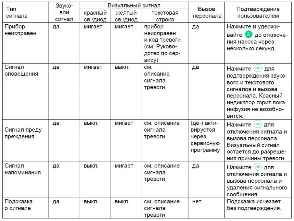
Сигналы и тревоги
Инфузомат Спэйс оснащен звуковой и визуальной сигнализацией тревоги.
Сигналы неисправности прибора
При появлении сигнала неисправности прибора инфузия немедленно прекращается. Нажмите кнопку включения для отключения прибора. Затем включите прибор снова. При повторном сигнале тревоги, закройте роликовый зажим, отсоедините пациента, откройте переднюю дверцу насоса и выньте систему. Прибор необходимо передать в сервисную службу.
Сигналы предупреждения и сигналя оповещения
Сигналы предупреждения:
Предупреждения подаются за несколько минут (в зависимости от сервисных установок) перед сигналами оповещения. Сигнал предупреждения включает звуковой тон, мигающий желтый индикатор и активирует систему вызова персонала (опция). Текстовое сообщение зависит от причины тревоги. Звуковой тон и система вызова персонала отключаются нажатием кнопки «ОК». Экран и индикатор остаются в режиме предупреждения вплоть до отключения сигнала оповещения. Во время подачи сигнала предупреждения инфузия не прерывается.
Объем почти введен
Введение заданного объема близко к завершению.
Время истекает
Заданное время инфузии скоро истечет.
Батарея разряжается
Батарея почти разряжена.
KVO активен
Объем введен/Время истекло и насос продолжает ин-фузию в режиме KVO — Открытая вена.
Ошибка соединения
Насос установлен в систему, хотя бы один из приборов в которой несовместим или неисправен. Применение этого прибора в системе не разрешается. Систему необходимо передать для проверки в сервисную службу.
Сигналы оповещения:
Сигналы оповещения приводят к прерыванию инфузии. Подается звуковой сигнал, мигает красный индикатор и активируется система вызова персонала. На экране появляется сообщения «Тревога» и информация о причине сигнала тревоги. Звуковой сигнал и система вызова персонала могут быть отключены кнопкой «ОК». Коррекция должна быть произведена в соответствие с причиной сигнала тревоги.
Объем введен
Заданный объем введен. Продолжите инфузию или введите новые параметры.
Время истекло
Заданное время инфузии истекло. Продолжите инфузию или введите новые параметры.
Батарея разряжена
Батарея разряжена. Подключите прибор к сети и/или замените батарею. Сигнал о разрядке батареи длится 3 минуты, после этого насос автоматически отключается.
Высокое давление
Обнаружена окклюзия в системе. Достигнут установленный уровень давления. Насос автоматически понижает скорость введения. Проверьте отсутствие петель и перегибов инфузионной системы и проходимость инфузионного фильтра и в/в катетера. Увеличьте уровень окклюзионного давления если необходимо.
KVO остановлен
Время работы в режиме KVO истекло. Продолжите инфузию или введите новые параметры.
Крышка батарейного отсека удалена
Крышка батарейного отсека установлена неправильно. Переустановите крышку до щелчка.
Время паузы истекло
Установленное время паузы истекло. Задайте новое время паузы или возобновите предыдущую инфузию.
Батарея не установлена
Использование насоса без батареи невозможно. Отключите прибор и установите батарею.
Привод блокирован
Шаговый двигатель не работает из-за высокого давления в системе. Отсоедините систему от пациента и переустановите ее.
Откалибруйте прибор
Параметры калибровки насоса были изменены (например, после обновления программного обеспечения). Выполните калибровку через сервисную программу. Выполняется Сервисной службой.
Датчик капель отсоединен
Прерван контакт с датчиком капель во время работы насоса. Проверьте правильность крепления датчика капель на капельной камере инфузионной магистрали. При необходимости переустановите датчик капель или задайте объем и продолжайте инфузию.
Проверьте линию на входе
Сигнал тревоги от входного датчика давления. Убедитесь, что роликовый зажим открыт и отсутствуют перегибы инфузионной линии между флаконом и насосом.
Воздушные пузырьки / Аккумулированный воздух
Воздух в системе. Осмотрите инфузионную систему, отключите ее от пациента и повторите ее заполнение при необходимости.
Нет капель
Датчик капель не обнаруживает капель. Возможные причины: инфузионный флакон пуст, роликовый зажим закрыт, датчик капель не установлен на капельную камеру. Проверьте отсутствие перегибов инфузионной системы, конденсацию на капельной камере (для удаления конденсата, встряхните капельную камеру).
Слишком мало капель
Количество падающих капель меньше заданной скорости инфузии. Возможные причины: отрицательное давление в стеклянном инфузионном флаконе. Для устранения — откройте вентиляционный клапан на капельной камере. Другие причины: инфузионный флакон пуст, роликовый зажим открыт не полностью, перегибы инфузионной линии. При обнаружении – устраните указанные препятствия.
Слишком много капель
Количество падающих капель больше заданной скорости инфузии. Возможные причины: инфузионная система повреждена, неправильно установлена в насос, либо не герметично подсоединена к катетеру.
Свободный поток
Капельная камера заполнена жидкостью или протечка в системе. Проверьте герметичность системы. Проверьте датчик капель.
Данные сброшены
Данные инфузии и насоса не возможно восстановить. Введите данные инфузии и настройки насоса заново.
Данные инфузии сброшены
Параметры инфузии не возможно восстановить. Введите параметры инфузии заново.
Время паузы истекло
Установленное время паузы истекло. Задайте новое время паузы или возобновите предшествующую инфузию.
Блок данных
Была попытка остановить или отключить насос без ввода кода. Введите правильный код для соответствующего продолжения инфузии или выключите насос.
Внимание: Если на экране появляется символ гаечного ключа и/или одновремен-но мигают желтый, красный и синий индикаторы – насос находится в сервисном режиме и его использование для лечения пациентов запрещено. Насос должен быть проверен сервисной службой.
Работа от батареи и обслуживание
Инфузомат Спэйс оснащен современной NiMH-батареей. Время работы насоса с новой батареей составляет 4 часа при скорости инфузии 100 мл/ч. Для оптимальной работы батареи, насос имеет защиту от перегрузки и полной разрядки. Батарея заряжается при включении прибора в сеть. При отключении от сети или в случае падения напряжения, насос автоматически переходит на питание от батареи.
Перед длительным хранением насоса (более 2-х недель без использования), батарея должна быть полностью заряжена, а затем извлечена из насоса. Перед извлечением (сменой) батареи всегда отсоединяйте насос от пациента и отключайте прибор.
Индикатор заряда батареи отображается на экране (низкий, средний, полный заряд). Для получения более детальной информации о состоянии батареи (время работы в часах и минутах) необходимо в меню «Статус» войти в раздел «Батарея».
Важная информация о самотестировании батареи:
Если символ батареи мигает во время работы от сети, батарея либо разряжена, либо быстро разряжается. В этом случае насос не должен отключаться от сети. Если необходимо экстренно отключить насос от сети, убедитесь, что остаточный заряд батареи достаточен для применения. Если символ батареи мигает непрерывно (>1ч), батарея должна быть проверена техническим персоналом и заменена при необходимости.
Обслуживание батареи
Для точной регулировки емкости батареи необходимо ее циклическое обслуживание. Насос запрашивает Пользователя о проведении обслуживания батареи каждые 30 дней. В режиме обслуживания батареи определяется возможная потеря емкости (например, из-за старения батареи) и затем емкость и время работы от батареи пересчитываются заново. После длительного хранения или длительной работы без обслуживания батареи, может случиться так, что время подачи предупредительного сигнала больше не будет поддерживаться. В этом случае необходимо проведение обслуживания батареи.
Для инициализации полной разрядки батареи на экране появляется запрос «Обслуживание батареи» и отображается кнопка «ОК». Для того, чтобы запустить процесс разрядки батареи нажмите кнопку «ОК» и кнопку «ВВЕРХ». При включении насоса процесс прерывается. Если обслуживание батареи необходимо продолжить, необходима повторная активация режима обслуживания. После полной разрядки батареи происходит ее полная зарядка. Полное обслуживание батареи длится приблизительно двенадцать часов.
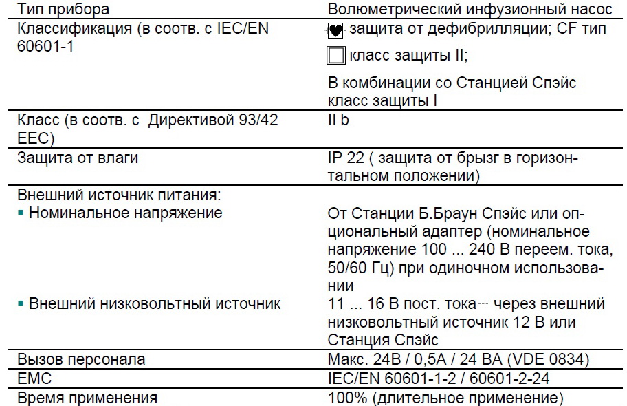
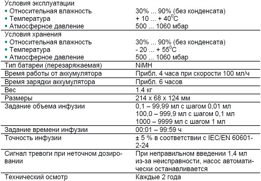
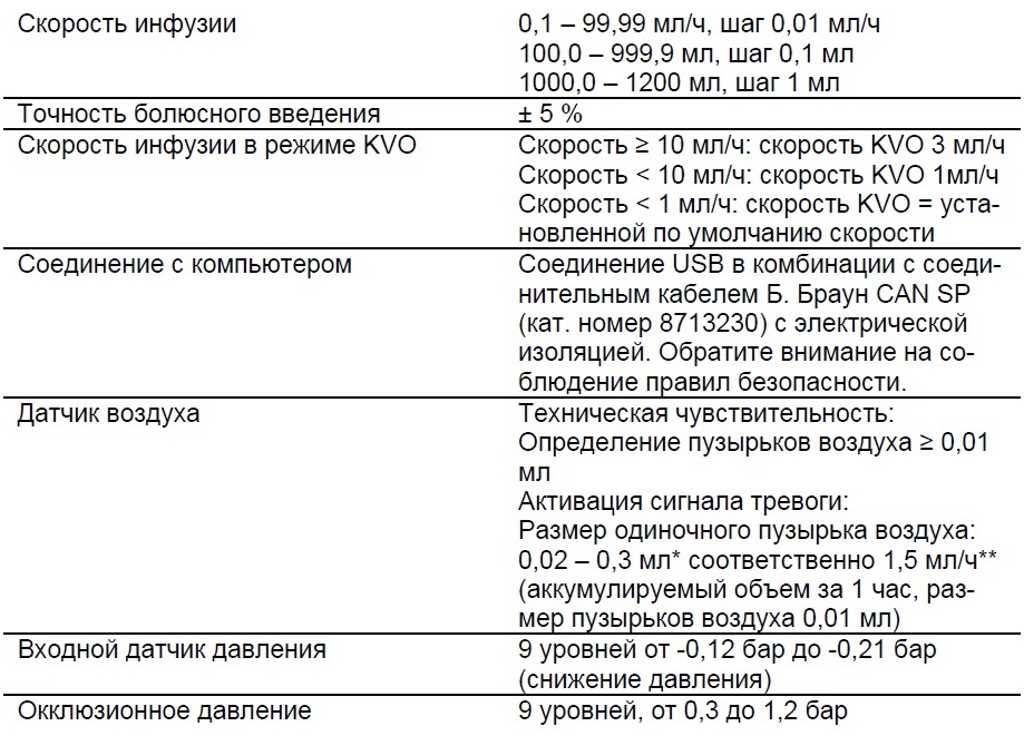
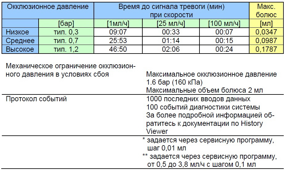
Инфузомат Спэйс B braun Технические характеристики
Ниже представлены технические характеристики Инфузомата Спэйс B braun.
Гарантия Инфузомат Спэйс B braun
Компания Б. Браун предоставляет 24 месяца гарантии, с момента поставки на каждый Инфузомат Спэйс (12 месяцев на каждый аккумулятор (Battery Pack SP)). Гарантия предусматривает ремонт или замену отдельных частей, вышедших из строя в результате конструкторских или производственных ошибок, а так же дефектов материала. Срок действия гарантии прекращается в случае модернизации или ремонта, проведенных Пользователем или посторонними лицами.
Гарантия не распространяется на устранение дефектов, вызванных неправильным / неумелым обращением или нормальным износом прибора.
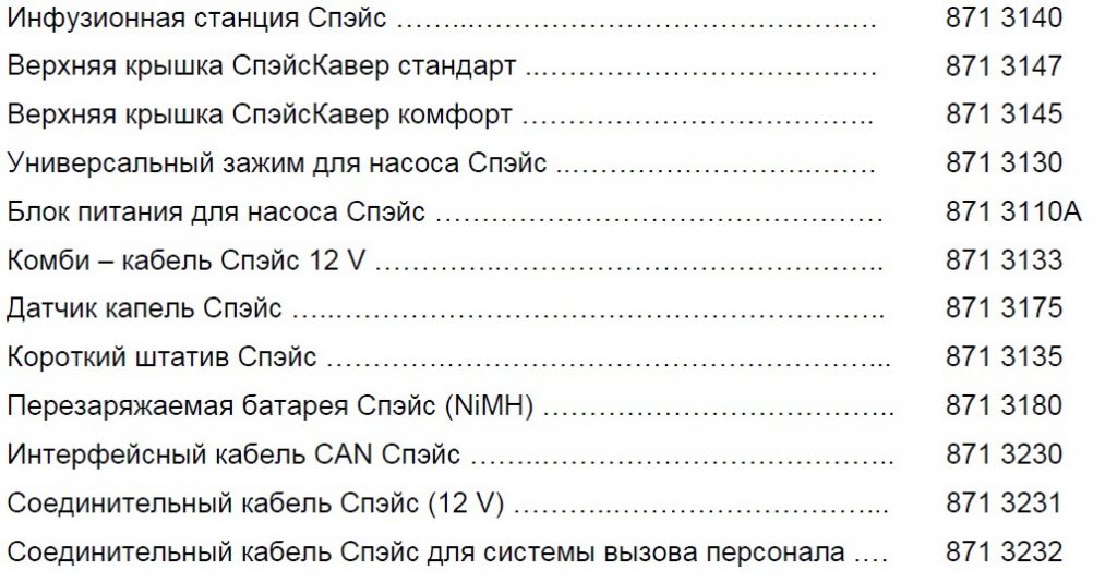
Каталожные номера Инфузомат Спэйс B braun и принадлежности
Б. Браун Инфузомат Спэйс (100 — 240 V) …………………………… 871 3050
Рекомендуемые принадлежности для насоса Б. Браун Инфузомат Спэйс:
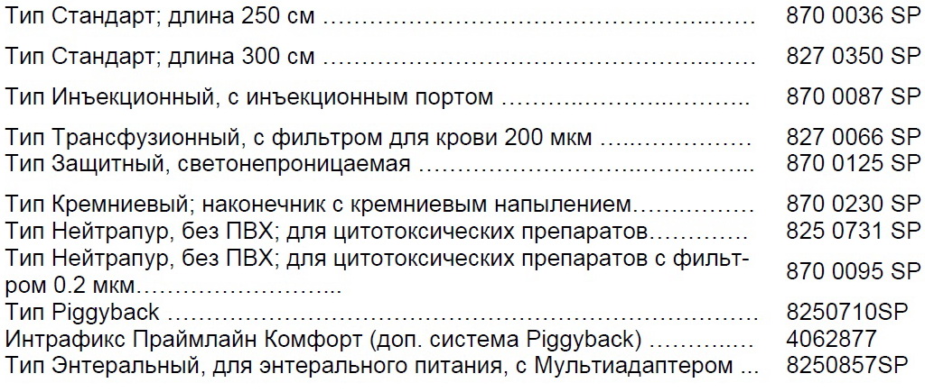
Инфузионные системы Инфузомат Спэйс:
Скачать инструкцию на Инфузомат Спэйс B braun
Скачать инструкцию и другую документацию на Инфузомат Спэйс B braun можно здесь.
Руководство пользователя ( user manual ) на русском языке Инфузомат Спэйс B braun скачать.
Регистрационное удостоверение Инфузомат Спэйс B braun скачать.
Так же смотрите Модуль Space Control ( Спэйс Контроль ) для SGC терапии.
Корзина (0)
Отложенные товары (0)
Минимальная сумма заказа составляет 500 РУБ. Если сумма Вашего заказа превышает 10 000 РУБ, мы доставим Вашу покупку по Москве в пределах МКАД БЕСПЛАТНО.
Ваша корзина пуста. Выберите интересующие вас товары в каталоге
В настоящий момент у вас нет отложенных товаров
Корзина (0)
Отложенные товары (0)
Минимальная сумма заказа составляет 500 РУБ. Если сумма Вашего заказа превышает 10 000 РУБ, мы доставим Вашу покупку по Москве в пределах МКАД БЕСПЛАТНО.
Ваша корзина пуста. Выберите интересующие вас товары в каталоге
В настоящий момент у вас нет отложенных товаров
B.Braun Space – насос инфузионный перистальтический (инфузомат)
Инфузионный перистальтический инфузомат B. Braun Space являет собой волюметрический насос для введения в вену лекарственных препаратов или же для обеспечения питания пациентов, которые не могут употреблять еду самостоятельно. Питательные смеси подаются с помощью гастростомы.
Минимальные габариты (21,4 х 6,8 х 12,4 см) и малый вес (всего 1,4 кг) упрощают транспортировку аппарата, позволяют разместить его в небольшом помещении.
Диапазон устанавливаемого времени инфузии довольно широкий – от 1 минуты до 99 часов 59 минут. При этом расчет скорости и дозировки происходит автоматически, что упрощает работу медицинского персонала. Болюсная подача жидкости происходит по требованию, с заданным объемом или дозой либо через интервал от 1 минуты до 24 часов.
Преимущества перистальтического насоса
В виду возможности задать невысокую скорость инфузии, а также гарантируемой точности дозировки препарата, устройство широко используется в педиатрии. Также аппарат незаменим в интенсивной терапии, применяется при обезболивании во время операций.
Преимущества модели Space перистальтического насоса:
-
Режим Piggyback позволяет проводить попеременно две инфузии с разными скоростями.
-
Болюсное (внутривенное) введение с функцией корректировки настроек по умолчанию и введения необходимых параметров вручную.
-
Возможность выбора ограничений дозировки препарата разной степени.
-
Пауза продолжительностью от 1 минуты до 24 часов, активируемая нажатием одной кнопки.
-
Выбор лекарства в специальной библиотеке, которая включает 1 500 наименований – 30 категорий.
-
Система защиты от попадания влаги при инфузии в горизонтальном положении, а также предотвращение дефибрилляции (нарушения ритма сердцебиения в процессе инфузионной терапии).
Если в процессе инфузии включается тревога по давлению, либо же система обнаруживает окклюзию, открытые дверцы или смену системы, настройки корректируются автоматически. Срабатывают прерыватели свободного потока жидкости, уменьшается скорость внутривенного введения, нормализуется входное давление. Все это повышает безопасность терапии, упрощает работу медицинских специалистов. Для конкретных препаратов можно задать звуковые сигналы тривоги.
Чтобы получить больше информации об оборудовании и сделать заказ, свяжитесь со специалистами магазина «Бравокислород». Мы заключаем договор с покупателем и гарантируем качество аппаратов. Поможем подобрать инфузомат с оптимальними характеристиками для вашого медицинского учреждения.
Гарантия: 1 год