-
Page 1
DVR User Manual For H.264 4/8/16-channel digital video recorder All rights reserved… -
Page 2
Do not block any ventilation openings. And ensure well ventilation around the machine Do not power off the DVR at normal recording condition! The correct operation to shut off DVR is to stop recording firstly, and then select “shut-down” button at the right of the menu bar to exit, and finally to cut off the power. -
Page 3: Table Of Contents
Digital Video Recorder User Manual Table of Contents Introduction ……………………………………7 1.1 DVR Introduction ………………………………….7 1.2 Main Features ……………………………………7 Hardware Installation ………………………………….10 2.1 Install Hard Drive &DVD Writer ………………………………10 2.1.1 Install Hard Drive ………………………………..10 …
-
Page 4
Digital Video Recorder User Manual Main menu setup guide ………………………………..24 4.1 Basic configuration ………………………………….. 25 4.1.1 System ………………………………….. 25 4.1.2 Time & date ………………………………….27 4.1.3 DST ……………………………………27 4.2 Live configuration ………………………………….28 … -
Page 5
6.1.5 Online information ………………………………..70 6.1.6 Manual alarm ………………………………… 71 6.1.7 Disk manager ………………………………… 71 6.1.8 Upgrade ………………………………….72 6.1.9 Logoff ……………………………………. 72 6.1.10 Device ………………………………….72 Remote Surveillance ………………………………….. 73 7.1 Accessing DVR ………………………………….73… -
Page 6
8.2 By Phones with Symbian ………………………………… 91 8.3 The operation method for iPhone mobile clients …………………………94 Appendix A FAQ…………………………………………………………………………………………………………………………………………………….100 Appendix B Calculate Recording Capacity………………………………………………………………………………………………..……………………..105 Appendix C Compatible Devices………………………………………………………………………………………………………………………………….106 Appendix D 4-CH DVR Specifications……………………………………………………………………………………………………………………………107 Appendix E 8-CH DVR Specifications…………………………………………………………………………………………………………………………….108 Appendix F 16-CH DVR Specifications…………………………………………………………………………………………………………………………..109… -
Page 7: Introduction
1.1 DVR Introduction This model DVR (Digital Video Recorder) is designed specially for CCTV system. It adopts high performance video processing chips and embedded Linux system. Meanwhile, it utilizes many most advanced technologies, such as standard H.264 with low bit rate, Dual stream, SATA interface, VGA output mouse supported, IE browser supported with full remote control, mobile view(by phones), etc., which ensure its powerful…
-
Page 8
Digital Video Recorder User Manual • Support saving recorded files with AVI standard format to a remote computer through internet RECORD & PLAYBACK • Record modes: Manual, Schedule, Motion detection and Sensor alarm recording • Support recycle after HDD full •… -
Page 9
Support remote time and event search, and channel playback with picture snap • Support remote PTZ control with preset and auto cruise • Support remote full menu setup, changing all the DVR parameters remotely • Support mobile surveillance by smart phones , symbian, WinCE, Iphone or Gphone, 3G network available •… -
Page 10: Hardware Installation
Digital Video Recorder User Manual Hardware Installation Notice: Check the unit and the accessories after getting the DVR. Please disconnect the power before being connected to other devices. Don’t hot plug in/out 2.1 Install Hard Drive &DVD Writer 2.1.1 Install Hard Drive Notice: 1.
-
Page 11: Install Dvd Writer
Digital Video Recorder User Manual Fig 2.2 Screw HDD 2.1.2 Install DVD Writer Notice: 1. The writers must be the compatible devices we recommend. Please refer to “Appendix C Compatible Devices” 2. This device is only for backup Step1: Unscrew and Open the top cover Step2: Connect the power and data cables.
-
Page 12: Front Panel Instructions
Digital Video Recorder User Manual Fig 2.4 Screw the Writer 2.2 Front Panel Instructions Notice: The pictures are only for reference; please make the object as the standard. The Front Panel interface for is shown as Fig 2.5: Fig 2.5 Front Panel…
-
Page 13: Rear Panel Instructions
Digital Video Recorder User Manual Item Name Function 1. Decrease the value in setup -/Backup 2. Enter backup mode in live Input number 10 and the above number together with other digital keys Digital button Input digitals or choose camera Enter button Confirm selection Direction/Multi-screen…
-
Page 14
Digital Video Recorder User Manual Fig 2.6 Rear Panel for 4-ch Item Name Description Video out Connect to monitor Connect to monitor as an AUX output channel by channel. Only video display, Spot out no menu show Audio out Audio output, connect to the sound box Connect to speed dome Connect to keyboard ALARM IN… -
Page 15
Digital Video Recorder User Manual Fig 2.7 Rear Panel for 8-ch Item Name Description Video out Connect to monitor Connect to monitor as an AUX output channel by channel. Only video display, Spot out no menu show Audio out Audio output, connect to the sound box Video in Video input channels from 1-8 POWER INPUT… -
Page 16
Digital Video Recorder User Manual The rear Panel interface for 16-ch is shown as Fig 2.8: Fig 2.8 Rear Panel for 16-ch Item Name Description Connect to speed dome Connect to keyboard ALARM IN Connect to external sensor1-16 HDMI port Connect to high-definition display device (optional) Network port VGA port… -
Page 17: Remote Controller
The interface of remote controller is shown in Fig2.9 Remote Controller. Fig 2.9 Remote Controller Item Name Function Power Button Soft switch off to stop firmware running. Do it before power off. INFOR Button Get information about the DVR like firmware version, HDD information…
-
Page 18: Control With Mouse
Operation processes with remote controller to control multi-DVR The device ID of the DVR is 0. When use of remote controller to control single DVR, it’s not necessarily to reset the device ID, user can do operation directly; when control multiple DVR with remote controller, please refer to below steps: Step1: Activate remote controller to control DVR: enable DVR: turn the IR sensor of the remote controller to the IR receiver that on the front panel, press the number key 8 twice, then input device ID (Range from: 0-65535;…
-
Page 19: Use Mouse
Digital Video Recorder User Manual 2. Change a mouse to try 2.5.2 Use Mouse The structure of the main menu is shown in Fig 2.9 Remote Controller. In live: Double-click left button on one camera to be full screen display. Double-click again to return to the previous screen display. Click right button to show the control bar at the bottom of the screen as Fig 2.9 Remote Controller.
-
Page 20: Basic Function Instruction
Digital Video Recorder User Manual Basic Function Instruction 3.1 Power On/Off Before you power on the unit, please make sure all the connection is good. 3.1.1 Power on Step1: connect with the source power; switch on the power button near the power port in the rear panel Step2: the device will be loaded, and the power indicator will display blue Step3: before start, a WIZZARD dialogue box will be pop-up (refer to below picture) and show some information about time zone and time setup.
-
Page 21: Power Off
Step2: click OK, the unit will power off after a while. Step3: disconnect the power 3.2 Login User can login and logout the DVR system. User cannot do any other operations except changing the multi-screen display once logout. Fig 3-1 Login ”…
-
Page 22: Live Preview
Digital Video Recorder User Manual 3.3 Live preview Fig 3-2 live preview interface The explanation of symbol in the live preview interface: symbol meaning symbol meaning Green Manual record or time record Alarm record Yellow Motion detection record Figure icon Move event 3.3.1 Live playback Click Play…
-
Page 23
Digital Video Recorder User Manual Fig 3-3 live playback… -
Page 24: Main Menu Setup Guide
Click the icon beside the screen display mode, a channel select dialog will appear as below: Take 8-channel DVR for example: user can tick off 8 channels form 1-ch to 16-ch at random to display the live pictures. Then click button to confirm the setting.
-
Page 25: Basic Configuration
Digital Video Recorder User Manual Fig 4-2 system setup 4.1 Basic configuration Basic configuration includes three sub menus: system、date& time and DST. 4.1.1 System Step1: enter into system configuration basic configuration system; refer to Fig 4-3:…
-
Page 26
Digital Video Recorder User Manual Fig 4-3 basic configuration-basic Step2: in this interface user can setup the device name, device ID, video format, max network users, VGA resolution and language. The definitions for every parameters display as below: Device name: the name of the device. It may display on the client end or CMS that help user to recognize the device remotely. Video format: two modes: PAL and NTSC. -
Page 27: Time & Date
Digital Video Recorder User Manual Note: When switch between VGA and CVBS will change the menu output mode, please connect to relevant monitor. Language: setup the menu language. Note: after changed the language and video output, the device needs to login again. 4.1.2 Time &…
-
Page 28: Live Configuration
Digital Video Recorder User Manual Fig 4-5 basic configuration-DST Step2: in this interface, enable daylight saving time, time offset, mode, start & end month/week/date, etc. Step3: click “default” button to resort default setting; click “apply” button to save the setting; click “exit” button to exit current interface. 4.2 Live configuration Live configuration includes four submenus: live, host monitor, SPOT and mask.
-
Page 29
Digital Video Recorder User Manual Fig 4-6 live configuration live Step2: tick off camera name; click “setting” button, a window will pop-up as Fig 4-7: Fig 4-7 live-color adjustment… -
Page 30: Host Monitor
Digital Video Recorder User Manual Step3: in this interface, user can adjust brightness, hue, saturation and contrast in live; click “default” button to resort default setting, click “OK” button to save the setting. Step4: user can setup all channels with same parameters, tick off “all”, then do relevant setup. Step5: click “default”…
-
Page 31: Spot
Digital Video Recorder User Manual 4.2.3 SPOT Step1: enter into system configuration live configuration SPOT; refer to Fig 4-9: Fig 4-9 live configuration-SPOT Step2: select split mode: 1×1and channel Step3: dwell time: the time interval for a certain dwell picture display switching to next dwell picture display Step4: selected the split mode, then setup current picture group.
-
Page 32
Digital Video Recorder User Manual Fig 4-10 live configuration-mask Setup mask area: click Setting button, enter into live image to press left mouse and drag mouse to set mask area, refer to below picture. Click Apply button to save the setting. Delete mask area: select a certain mask area, click left mouse to delete that mask area, click Apply button to save the setting. -
Page 33: Record Configuration
Digital Video Recorder User Manual Live image mask area 4.3 Record configuration Record configuration includes five sub menus: enable, record bit rate, time, recycle record and stamp. 4.3.1 Enable Step1: enter into system configuration record configuration enable; refer to Fig 4-11:…
-
Page 34
Digital Video Recorder User Manual Fig 4-11 record configuration-enable Step2: tick off record, audio and record time Step3: user can setup all channels with same parameters, tick off “all”, then to do relevant setup. Step4: click “default” button to resort default setting; click “apply” button to save the setting; click “exit” button to exit current interface. Definitions and descriptions of Record: Parameter Meaning… -
Page 35: Record Stream
Digital Video Recorder User Manual 4.3.2 Record stream Step1: enter into system configuration record configuration record bit rate; refer to Fig 4-12: Fig 4-12 record configuration-record bit rate Step2: setup rate, resolution, quality, encode and max bit stream Step3: user can setup all channels with same parameters, tick off “All”, then to do relevant setup. Step4: click “default”…
-
Page 36: Time
Digital Video Recorder User Manual Resolution Support CIF and D1 Quality The quality of recorded images. The higher the value is, the clearer the recorded image is. Six options: lowest, lower, low, medium, higher and highest. Encode VBR and CBR Range from: 64 Kbps、128 Kbps、256 Kbps、512 Kbps、768 Kbps、1Mbps、…
-
Page 37: Recycle Record
Digital Video Recorder User Manual Expire time: the hold time of saved records. If the set date is overdue, the record files will be deleted automatically. Step2: user can setup all channels with same parameters, tick off “all”, then to do relevant setup. Step3: click “default”…
-
Page 38: Schedule Configuration
Digital Video Recorder User Manual Step2: tick off camera name, time stamp; click Set button, user can use cursor to drag the camera name and time stamp in random positions, refer to below Figures: Before drag after drag Step3: user can setup all channels with same parameters, tick off “all”, then to do relevant setup. Step4: click “default”…
-
Page 39
Digital Video Recorder User Manual Fig 4-15 schedule configuration-schedule Step2: select channel, double-click and a dialog box will pop-up as Fig 4-16, user can edit week schedule: Fig 4-16 schedule-week schedule… -
Page 40: Motion
Digital Video Recorder User Manual ① Click “add” button to add a certain day schedule; click “delete” button to delete the selected schedule; Copy: user can copy the specify schedule to other dates. Click “OK” button to save the setting, click “Exit” button to exit current interface. ②…
-
Page 41: Sensor
Digital Video Recorder User Manual 4.4.3 Sensor Step1: enter into system configuration schedule configuration alarm; refer to Fig 4-18: Step2: the setup steps of alarm are familiar with schedule; user can refer to 4.4.1 Schedule for details. Note: the default schedule of sensor is full-selected, that is, the color of schedule setting interface is blue. Fig 4-18 schedule configuration-sensor 4.5 Alarm configuration Alarm configuration includes five sub menus: sensor, motion, video loss, other alarm and alarm out.
-
Page 42
Digital Video Recorder User Manual Step1: enter into system configuration alarm configuration sensor basic; refer to Fig 4-19: Fig 4-19 alarm configuration-sensor-basic Step2: enable sensor alarm, set the alarm type according to triggered alarm type. Two option: NO and NC. Step3: user can setup all channels with same parameters, tick off “all”, then to do relevant setup. -
Page 43
Digital Video Recorder User Manual Fig 4-20 alarm configuration-sensor-alarm handling Step2: select hold time, click Trigger button, and a dialog box will pop-up as Fig 4-21: Fig 4-21 alarm handling-trigger Step3: tick off Buzzer, there will be triggered buzzer alarm out; Full screen alarm: when triggered alarm, there will pop up full screen alarm;… -
Page 44
Digital Video Recorder User Manual button to exit the current interface. To record: tick off recoding channels, it will record the camera when alarm triggered. Click OK button to save the setting; click Exit button to exit the current interface. To P.T.Z: set linked preset and cruise for alarm. -
Page 45: Motion
Digital Video Recorder User Manual 4.5.2 Motion Motion includes two sub menus: motion and schedule. ① Motion Step1: enter into system configuration alarm configuration motion; refer to Fig 4-23: Fig 4-23 alarm configuration-motion Step2: enable motion alarm, set alarm hold time which means time interval between two adjacent detective motions. If there is other motion detected during the interval period which is considered continuous movement;…
-
Page 46
Digital Video Recorder User Manual Fig 4-24 motion-area Step5: in the Area interface, user can drag slide bar to set the sensitivity value (1-8), the default value is 4. The higher the value is the higher sensitivity you get. Due to the sensitivity is influenced by color and time (day or night), user can adjust its value according to the practical conditions;… -
Page 47: Video Loss
Digital Video Recorder User Manual Step6: user can setup all channels with same parameters, tick off “all”, then to do relevant setup. Step7: click “default” button to resort default setting; click “apply” button to save the setting; click “exit” button to exit current interface. ②…
-
Page 48: Other Alarm
Digital Video Recorder User Manual Fig 4-26 alarm configuration-video loss Step2: the setup steps of video loss trigger are familiar with alarm handling; user can refer to Chapter 4.5.1 Sensor alarm handling for more details. Step3: user can setup all channels with same parameters, tick off “all”, then to do relevant setup. Step4: click “default”…
-
Page 49: Alarm Out
Digital Video Recorder User Manual Step1: enter into system configuration other alarm; refer to Fig 4-27: Step2: select a hard disk in the pull down list box, when the disk capacity is lower than that value, there will appear some text information on the lower right of the live image.
-
Page 50: Network Configuration
Digital Video Recorder User Manual Note: the default schedule of motion detection is full-selected, that is, the color of schedule setting interface is blue. ③ Buzzer Step1: enter into system configuration buzzer; Step2: tick off Buzzer, set buzzer alarm hold time 4.6 Network configuration Network configuration includes two submenus: network and network stream.
-
Page 51
Step3: Tick off the «Obtain IP address automatically», the device will distribute IP address, subnet mask, gateway IP and DDNS service; Step4: enable PPPOE, user can directly connect the DVR to internet via ADSL, then input the user name and password; click TEST button to test the effectively of relevant information. -
Page 52
Digital Video Recorder User Manual Fig 4-30 Register dialog box (2) Login Step 1: Return to homepage after registering successfully. Step 2: Click «Account Manager» on the right of homepage to login. Step 3: Input the username and password with the information that you have registered. Step 4: Click «Enter»… -
Page 53
2. Setup in the DVR ⑴ DOMAIN Domain is set in ‘1 1. Apply the Domain Name’. According to the example above, the domain is ‘DVR.www.88IP.net’. ⑵ USER ID Username of registered which is set in ‘(1) Register in the Web’. According to the example above, user ID is ‘abc’. -
Page 54: Network Stream
② Enter into configuration interface of the router, map the server port and IP address. Click Save button to save the setting ③ Login IE browser and input registered domain name “www.tester123.88ip.net”, connect to DVR client. Note: If the value changed, user needs to add the port number when typing IP address in IE address blank .i.e. set HTTP port to 82, IP address: http://192.168.0.25, user needs to input that address:…
-
Page 55
Digital Video Recorder User Manual Fig 4-33 network configuration-sub stream Step2: select fps, resolution, quality, encode and max bit rate Step3: user can setup all channels with same parameters, tick off “all”, then to do relevant setup. Step4: click “default” button to resort default setting; click “apply” button to save the setting; click “exit” button to exit current interface. Definitions and descriptions of network stream: Parameter Meaning… -
Page 56: User Management Configuration
Digital Video Recorder User Manual options: lowest, lower, low, medium, higher and highest. Encode VBR and CBR Range from: 64 Kbps、128 Kbps、256 Kbps、512 Kbps、768 Kbps、1Mbps、2 Mbps Max bit rate 4.7 User management configuration Step1: enter into system configuration user management configuration; refer to Fig 4-34: Fig 4-34 user management configuration Step2: click Add button, a dialog box will pop-up as Fig 4-35: Fig 4-35 add-general…
-
Page 57
Note: when the default value of binding PC MAC address is 0, the user is not bind with the specify computer; the, the user can log in DVR on the binding computer after set the specific binding MAC address. ②… -
Page 58: Configuration
Digital Video Recorder User Manual 4.8 P.T.Z configuration P.T.Z configuration includes two submenus: serial port and advance ① Serial port Step1: enter into system configuration P.T.Z configuration serial port; refer to Fig 4-37: Fig 4-37 P.T.Z configuration-serial port Step2: tick off Enable, setup the value of address, baud rate and protocol according to the settings of the speed dome. Step3: user can setup all channels with same parameters, tick off “all”, then to do relevant setup.
-
Page 59
Digital Video Recorder User Manual Parameter Meaning Address The address of the PTZ device Baud rate of the PTZ device. Range form: 110、 300、 600、 1200、 2400、 4800、 Baud rate 9600、19200、34800、57600、115200、230400、460800、21600. Communication protocol of the PTZ device. Range from: NULL、PELCOP、 Protocol PELCOD 、… -
Page 60
Digital Video Recorder User Manual Fig 4-39 advance-preset setting a. in the preset set interface, click Setting button, a dialog will pop-up as Fig 3-40: Fig 3-40 preset set-setting b. user can control the dome rotates up, up left, down, right down, left , left down, right and up right and stop rotating; adjust the rotate speed and the value of zoom, focus and iris of the dome;… -
Page 61
Digital Video Recorder User Manual Step3: in the Advance interface, click cruise “Setting” button, a dialog box will pop-up as Fig 4-41: Fig 4-41 cruise set a. click Add button to add cruise line in the list box (max 8 cruise line can be added); select a cruise line, click Setup button, a dialog box will pop-up as Fig 4-42: Fig 4-42 cruise set-modify cruise line… -
Page 62
Digital Video Recorder User Manual b. click Add icon to set the speed and time of preset point; select a preset point, click Delete icon to delete that preset point; click Modify icon to modify the setting of a preset point. User can click those icons to adjust the position of preset point. -
Page 63: Record Search & Playback And Backup
Digital Video Recorder User Manual Record search & playback and backup Search configuration includes three submenus: time search, event search and file manager. 5.1 Time search Step1: enter into Search configuration time search; refer to Fig 5-1: Fig 5-1 Search configuration-time search Step2: select channel, screen display mode, the highlight date in the calendar means have record data Step3: select a date, press Search button, click the time grid to set the play start time or input play record time manually.
-
Page 64: Event Search
Digital Video Recorder User Manual Playback buttons Note: when the monitor resolution is VGA800*600, the time search interface will appear a hide button, click this button, the whole interface can be expanded. 5.2 Event search Step1: enter into Search configuration event search; refer to Fig 5-2: Fig 5-2 Search configuration-event search…
-
Page 65: File Manager
Digital Video Recorder User Manual Step2: click Search button, the searched event information will displayed in the event list box, user can select date, channel, tick off Motion, Sensor or All accordingly. Step3: double check a certain record file to playback. Note: when the monitor resolution is VGA800*600, the event search interface will appear a hide button, click this button, the whole interface can be expanded.
-
Page 66: Backup
Digital Video Recorder User Manual Step3: tick off “All” button; user can lock/unlock or delete all files in the file manager column. Step4: double click an unlocked item to playback. Note: when the monitor resolution is VGA800*600, the file manager interface will appear a hide button, click this button, the whole interface can be expanded.
-
Page 67
Digital Video Recorder User Manual Fig 5-5 backup information Step4: in the backup information interface, user can check the relevant information of backup files, storage type, save file type, etc. click Apply button to starting backup. Note: when the monitor resolution is VGA800*600, the file manager interface will appear a hide button, click this button, the whole interface can be expanded. -
Page 68: Manage Dvr
Digital Video Recorder User Manual Manage DVR 6.1 Check system information Check system information includes five submenus: system, event, log, network and online user. 6.1.1 System information In this interface, user can check the hardware version, MCU version, kernel version, device ID, etc. refer to Fig 6-1: Fig 6-1 system information 6.1.2 Event information…
-
Page 69: Log Information
Digital Video Recorder User Manual Fig 6-2 event information 6.1.3 Log information In this interface, user can check relevant log information according to set date; refer to Fig 6-3: Fig 6-3 log information…
-
Page 70: Network Information
Digital Video Recorder User Manual 6.1.4 Network information In this interface, user can check relevant parameters of network; refer to Fig 6-4: Fig 6-4 network information 6.1.5 Online information In this interface, user can check the details of the current connection of online users; refer to Fig 6-5: Fig 6-5 online information…
-
Page 71: Manual Alarm
Digital Video Recorder User Manual 6.1.6 Manual alarm In this interface, user can check the relevant parameters of manual alarm; refer to Fig 6-6: Fig 6-6 manual alarm 6.1.7 Disk manager Step1: enter into disk manager interface; refer to Fig 5-7: Fig 6-7 disk manager Note: please format the hard disk before record.
-
Page 72: Upgrade
At present, it only supports USB update. Get the firmware from your vendor when there is a new firmware version, and make sure it is corresponding with the DVR. User can check the USB information in Disk manager. 6.1.9 Logoff Click Log off icon, a log off dialogue box will popup, click OK button, the device will log off.
-
Page 73: Remote Surveillance
Remote Surveillance 7.1 Accessing DVR If making remote view, the DVR must connect with LAN or internet. Then enable network server in the unit. Please refer to 4.6 Network Configuration. This unit supports IE browser, not any client software installed. In addition, it supports XP and Vista.
-
Page 74
Notice: If HTTP port is not 80, other number instead, need add the port number after IP address. For example, set HTTP port as 82, need input IP address like 192.168.0.25:82. User name and password here are the same with that used on the DVR. The default is admin and 123456. -
Page 75: On Wan
Notice: Forwarding block may be different in different routers and server, please check your router manual. If users want to utilize dynamic domain name, need apply for a domain name in a DDNS server supported by the DVR or router. Then add to the DVR or router.
-
Page 76: The Remote Live Preview Interface As Below
Digital Video Recorder User Manual 7.2 The remote live preview interface as below: Fig 7-2 Remote live preview interface…
-
Page 77
Fig 7-3 Channel select dialog Take 8-channel DVR for example: user can tick off channels form 1-ch to 16-ch at random to display the live pictures, 8 channels can be selected at most. Then click OK button to confirm the setting. -
Page 78
Digital Video Recorder User Manual Fig 7-4 Single snap User can multiple pictures , select the picture number from Frame pull down list box, such as 3, tick off “Title” and “Time”, it will show capture title and time on the snap pictures simultaneously. Refer to Fig 6-5: Fig 7-5 Multi-picture snap Click “Browse”… -
Page 79
Digital Video Recorder User Manual Color adjustment: Drag the slide bar to adjust Brightness, Contrast, Hue, and Saturation. Click Default to reset them to original value. Buttons Description Drag the scroll bar to adjust the brightness of channel Drag the scroll bar to adjust the contrast of channel Drag the scroll bar to adjust the saturation of channel Drag the scroll bar to adjust the hue of channel Click this button to recover the default value of brightness, contrast, saturation and hue. -
Page 80
Fig 7-6 right key sub menu Stream: this DVR supports master stream and sub stream. Master stream has higher frame rate, max 25FPS(PAL)/30 FPS(NTSC)for every channel, but it needs higher network bandwidth simultaneously; second stream has low frame rate, max 6FPS (PAL)/7FPS(NTSC) for every channel, it requires low network bandwidth. -
Page 81: Remote Playback & Backup
Digital Video Recorder User Manual 7.3 Remote playback & backup 7.3.1 Remote playback Click button to enter into record playback interface, refer to Fig 7-7: Select the record date and channels; double-click the file name in the record file list box, user can play that file and preview the picture. Fig 7-7 Play record file interface…
-
Page 82
Digital Video Recorder User Manual This DVR supports remote time search, event search and file management. By Time Search: Step1: Enter into Search time search; refer to Fig 7-8: Fig 7-8 time search interface Step2: click “Search” button. The record data will be displayed in the data information list box; the highlight date in the area② means have record… -
Page 83
Digital Video Recorder User Manual data, click those data; select the record channels in area③ Step3: User can set the data playing time and display mode in the area① as required Step4: Select certain item from the data information list box, click “play” button to playback Step5: Click the relevant buttons in the interface;… -
Page 84
Digital Video Recorder User Manual By Event Search: Step1: Enter into Search event search; refer to Fig 7-10: Fig 7-10 event search interface Step2: click the highlight date and select record channels and then tick off the event type: motion and sensor, click “search” button Step3: the events will be display in the event list box, double-click certain item to playback File Management Step1: Enter into Search file management;… -
Page 85
Digital Video Recorder User Manual Fig 7-11 file management interface Lock: select certain file item in the file list box, click “Lock” button to lock this file that ca not be deleted or overlaid Unlock: select a locked file, click “unlock” button to unlock this file Delete: select an unlock file, click “delete”… -
Page 86: Remote Backup
Digital Video Recorder User Manual 7.3.2 Remote backup Click Backup button to enter into backup interface, refers to Fig 7-12: Fig 7-12 remote backup interface Step1: select channels, set the start and end time, then click “search’ button, the file information will be displayed in the file list box Step2: select backup files, click “browse”…
-
Page 87: Remote System Configuration
Click Config to enter into the below interface refer to Fig 7-13: Fig 7-13 remote menu setup The sub menu lists and the options in every item are similar with those on the DVR. Please refer to Chapter 3 Main Menu Setup Guide for more details.
-
Page 88: Mobile Surveillance
Mobile Surveillance This DVR supports mobile surveillance by Iphone, Gphone or smart phones with WinCE and symbian OS. At the same time, it supports 3G network. We tested Dopod D600 (WM5) and Dopod S1 (WM6), which work fine with the DVR.
-
Page 89
Digital Video Recorder User Manual Step3:Click “Yes” to start downloading and installing: Step4:PCam will be opened automatically after installed… -
Page 90
It will show the picture if access successfully. Step6: Camera 1 is the default channel after login. Change the channel in rolling-down menu of “Channel”: Notice: User name and password here are the same with that used on the DVR. The default is admin and 123456. -
Page 91: By Phones With Symbian
Firstly enable the network access on mobile phone. Then run Web browser. Step2: Input the DVR server’s IP address in a new-built bookmark. Click this bookmark to connect to the DVR. Step3: A welcome window will pop up and requires a package. Click the software name to download Step4:…
-
Page 92
Digital Video Recorder User Manual Live view: to do mobile live view Image view: to check the pictures snapped in live view System setting: Login setting and Alarm setting. Help: function indication and help Step7: Click System setting—>Login Setting to enter login interface. -
Page 93
Step9: Enter Live View, it will connect the server and display pictures. Notice: User name and password here are the same with that used on the DVR. The default is admin and 123456. Step10: In Live View, users can do snapshot, change channels and control PTZ. -
Page 94: The Operation Method For Iphone Mobile Clients
Digital Video Recorder User Manual 8.3 The operation method for iPhone mobile clients At present, the software only supports version of iPhone os2.2 and above, if phone firmware lower than this version please upgrade it. Below is the operation method for iPhone mobile clients: Step1:Enter into App Store function of iPhone function to search “SuperCam”, the required programs will be displayed on the top of search box Step 2: Enable “search”…
-
Page 95
Digital Video Recorder User Manual Step 3: Click SuperCam, enter into “introduce” interface and click FREE”, it will change into “INSTALL” Step 4: Enter into iTunes Store password, click “OK”will display below interface Note: if it was the first time for user to operate please enter into user ID; if there is no Store account, user need to apply one. Step 5: Just be patient to download and install. -
Page 96
Digital Video Recorder User Manual Step 6: Click “System setting”, enter into login interface. Enter into server’s IP address (or domain name), user’s ID and password. Click Back to save. Step 7: Click Live View, the default Cam1 picture will be displayed. Click to capture picture. -
Page 97
Digital Video Recorder User Manual Step 8: On function interface, click Image View to view the captured picture. Click to switch to next or previous picture. Click delete the current picture. Iphone help… -
Page 98
Digital Video Recorder User Manual Pic1 Pic2 Pic3 Live View After successfully installed SuperCam software, Click on System Setting (Pic 1), and then input Server IP address or Domain, User name and password to log in (Pic 2). If connected successfully, it will go to Live View of CH1 as default (Pic 3), please choose other desired channels from channel button underneath. -
Page 99
Digital Video Recorder User Manual Image View Pic 4 Pic 5 Item Buttons Explanations Item Buttons Explanations Item Buttons Explanations Previous picture Next Picture The first Picture The last picture Delete Search Pictures, search page as Pic 5… -
Page 100: Appendix A Faq
Connection problem. Please check the cable and the ports of camera and DVR. b. Camera problem. Please check the cameras. c. The video format of the DVR is different from that of the cameras. Please change DVR system format. Q4. Cannot find HDD a.
-
Page 101
Digital Video Recorder User Manual Q5. Cannot record a. Don’t format HDD. Please format it manually first. b. Don’t enable record function or incorrect setup. Please refer to Chapter 5 Record search & playback and backup. c. HDD is full and not enables recycle function. Please refer to 4.3 Record configuration. Chang a new HDD or enable recycle. d. -
Page 102
Fig7-1 Fig7-2 Q8: How to deal with when DVR starts, it displays “please wait…”all the time First possible reason: hard-disk cable and data cable are not well connected. Solution: Please check the connection of hard-disk cable and data cable and make sure they are well connected; If still not working, please unplug… -
Page 103
When DVR only uses one hard disk, the hard disk removed from one to another same type DVR can work normally without format. However, when a DVR adds to a new hard disk, it will identify the hard disk as a new one and inquire whether to format no matter whether this hard disk used or not in another same type DVR before. -
Page 104
Digital Video Recorder User Manual Motherboard Intel 845 512M NVIDIA GeForce MX440/FX5200 ATIRADEON 7500/X300 Windows 2000(SP4 above) /Windows XP(SP2 above) /VISTA DirectX Q13: What are the PC configurations for 16-ch real time product with fully open channel mainstream? PC Module Parameters Intel Core(TM)2 Duo CPU E4600 Motherboard… -
Page 105: Appendix B Calculate Recording Capacity
Digital Video Recorder User Manual Appendix B Calculate Recording Capacity Users can calculate the size of hard disk according to the saving time and DVR recording settings. The DVR uses fixed video bit rate. The below are the details at different settings.
-
Page 106: Appendix C Compatible Devices
Digital Video Recorder User Manual Appendix C Compatible Devices 1. Compatible USB drive after test. Brand Capacity 512MB, 1G, 2GB Netac Kingston Aigo Smatter vider SanDisk Tab C.1 Compatible USB drive 2. Compatible SATA CD/DVD writers after test Brand Model TECLAST GH22NP20/TL-22XD BENQ…
-
Page 107: Appendix D 4-Ch Dvr Specifications
Digital Video Recorder User Manual Appendix D 4-CH Specifications Compression format Standard H.264 Baseline Composite:1.0V p-p/75Ω,BNC×2 , VGAX1 Video output Composite:1.0V p-p/75Ω,BNC×4 Video input VGA Resolution 1280*1024 /1024*768/ 800*600 Record Resolution 352*288/704*576 (PAL), 352*240/704*480(NTSC) Display Frame Rate 100FPS (PAL), 120FPS (NTSC)
-
Page 108: Appendix E 8-Ch Dvr Specifications
Digital Video Recorder User Manual Appendix E 8-CH Specifications Compression format Standard H.264 Baseline Composite:1.0V p-p/75Ω,BNC×2 , VGAX1 Video output Composite:1.0V p-p/75Ω,BNC×8 Video input VGA Resolution 1280*1024 /1024*768/ 800*600 Record Resolution 352*288/704*576 (PAL), 352*240/704*480(NTSC) Display Frame Rate 200FPS (PAL), 240FPS (NTSC)
-
Page 109: Appendix F 16-Ch Dvr Specifications
Digital Video Recorder User Manual Appendix F 16-CH Specifications Compression format Standard H.264 Baseline Composite:1.0V p-p/75Ω,BNC×2, VGAX1 Video output Composite:1.0V p-p/75Ω,BNC×16 Video input VGA Resolution 1280*1024 /1024*768/ 800*600 Record Resolution 352*288/704*576 (PAL), 352*240/704*480(NTSC) Display Frame Rate 400FPS (PAL), 480FPS (NTSC)
- Каталог
- Архив товаров
- Falcon Eye FE-0104H

- Режим работы: Пентаплекc
- Алгоритм сжатия видео: H.264
- Алгоритм сжатия аудио: 8kHz х 16 bit G.711
- Видеовходы: 4 х BNC 1.0 Vpp 75 Ом
- Видеовыходы: 1 х BNC, SPOT, VGA
- Аудиовход: 4 х RCA
- Аудиовыход: 1 х RCA
- Режим отображения: 25 к/с полный кадр, PIP, ZOOM
- Скорость записи (CIF): 100 к/с разрешение 320х288
- Скорость записи (HD1): 100 к/с разрешение 704х288
- Скорость записи (D1): 100 к/с разрешение 704х576
- Режимы записи: ручной, по расписание, по событию, по детектору
- Накопитель: 1 х HDD (SATA), до 2 Тб
- Детектор движения: зоны 14х14, 4 уровня
- Тревожные входы/выходы: 4/1
- Сеть Ethernet: 10/100 BaseT
- Сетевые протоколы:DDNS, DHCP, PPPoE, TCP/IP, 3G
- Доступ по сети: CMS для Win XP, Vista, Win 7, Mac OС
- Поддержка браузеров: IE 6-9, Chrome, Opera, FireFox, Apple Safari
- Поддержка мобильных устройств: Android, iPhone, iPAD, Blackberry, Symbian, Win CE
- Архивирование: порт USB (Backup), по сети
- PTZ — устройства: RS-485, Pelco P, Pelco D, Panasonic
- Мышь: В комплекте
- Питание: DC 12 V, 3A
- Габаритные размеры: 274х215х45 мм
4-х канальный цифровой регистратор, являющийся удачным решением для построения системы видеонаблюдения. Компактные размеры и простота в использовании являются неоспоримым преимуществом этой модели. Функциональной особенностью этого видеорегистратора видеонаблюдения является наличие тревожных выходов и возможность управления с лицевой панели регистратора. Видеорегистратор Falcon Eye работает в режиме пентаплекс и использует технологию компрессии H.264, что позволяет экономить до 40% места на HDD. К видеорегистратору может осуществляться удаленный доступ через Интернет практически с любых устройств, поддерживаются популярные модели 3G модемов.
Данная модель мини видеорегистратора снята с производства!
Фотографии 4-канального H.264 видеорегистратора Falcon Eye для систем видеонаблюдения


Данная модель мини видеорегистратора снята с производства!
Добавить комментарий
- Manuals
- Brands
- H.264 Manuals
- DVR
- 4 CH Multiplex DVR
- User manual
-
Contents
-
Table of Contents
-
Bookmarks
Quick Links
Related Manuals for H.264 4CH
Summary of Contents for H.264 4CH
-
Page 2: Table Of Contents
User Manual Table of Contents Date: 08/05/2010 VER: 1.0 ……………………………………………………………….. 4 INSTALLATION SAFEGUARDS Specification ……………………………………………………………….. 5 CHAPTER 1.PREFACE ……………………………………………………………….. 6 1-1.Initial Setup ……………………………………………………………….. 6 ……………………………………………………………….. 8 CHAPTER 2.HARDWARE CONFIGURATION 2-1.FRONT Panel Layout ……………………………………………………………….. 8 2-2.Rare Panel Layout ……………………………………………………………….. 10 2-3.Hard Disk Drive ………………………………………………………………..
-
Page 3
User Manual ……………………………………………………………….. CHAPTER 7.EVENT 7-1.ALARM ……………………………………………………………….. 7-2.MOTION ……………………………………………………………….. 7-3.VIDEO LOSS ……………………………………………………………….. 7-4.ALARM-OUT ……………………………………………………………….. 7-5.BUZZER ……………………………………………………………….. CHAPTER 8.NETWORK ……………………………………………………………….. 8-1.LAN ……………………………………………………………….. 8-2.NOTIFICATION ……………………………………………………………….. ……………………………………………………………….. CHAPTER 9.SYSTEM 9-1.INFORMATION ……………………………………………………………….. 9-2.DATE/TIME ……………………………………………………………….. 9-3.STORAGE ……………………………………………………………….. 9-4.USER ……………………………………………………………….. 9-5.LOGOUT ……………………………………………………………….. CHAPTER 10.SEARCH & PLAYBACK ……………………………………………………………….. -
Page 4: Installation Safeguards
User Manual INSTALLATION SAFEGUARDS All the safety and operating instructions should be read before operation. Environment Conditions for Installation 1. To prevent electric shock or other hazard, do not expose this unit to rain, moisture, or dust. 2. Place this unit in a well-ventilated place and do not place heat-generating objects on this unit. 3.
-
Page 5: Specification
16 CH VIDEO IN / OUT Video Inputs 4 BINC 8 BNC 16 BNC 1 BNC, 1 VGA, 1 Spot(Analog) Video Outputs 4CH Loop outs 8 Loop outs 16 Loop outs Audio Input 1 ch 2 ch 4 ch Audio Output…
-
Page 6: Chapter 1.Preface
User Manual CHAPTER PREFACE CHAPTER 1. PREFACE 1. Initial Setup As all of the needed connections are made to the DVR unit, follow the instruction provided below to configure Date and Time, Camera, Recording and Network configuration Before powering up Make sure the unit is properly connected with Video Output Device, Cameras and protected by connecting to power surge protector.
-
Page 7
User Manual Main Menu Icons There are six main menu icons: DISPLAY, RECORD, EVENT, NETWORK, SYSTEM. User must perform «Date and Time Setup», «HDD format», «Factory Default Procedure» and «Reboot» under following circumstances. 1. Operating the DVR unit for the first time. 2. -
Page 8: Chapter 2.Hardware Configuration
User Manual HARDWARE CHAPTER CONFIGURATION CHAPTER 2. HARDWARE CONFIGURATION 1. FRONT Panel Layout [1U CASE] [21U CASE] DVD-R DRIVE For Backup purposes. USB PORT Firmware Updates and USB backup IR Receiver. IR Remote Controller Receiver. POWER LED This LED will illuminate when the system is powered on This LED will illuminate when there is activity on the HDD HDD LED This LED will illuminate when there is a remote connection…
-
Page 9
User Manual MODE To change the live view screen division To initiate video sequence mode ZOOM To digitally zoom into live video Enable picture in picture MENU To open the «Live View Menu» from the Live View Screen Switch audio channel. AUDIO To show the PTZ control Freeze in full screen or split screen… -
Page 10: Rear Panel Layout
User Manual CHAPTER 2. HARDWARE CONFIGURATION 2. Rear Panel Layout 1U&2U — 4CH 1U&2U — 8CH 1U — 16CH 2U — 16CH Page…
-
Page 11
User Manual RS-485 For connection to PTZ cameras. ALARM OUT For Relay output. ALARM IN 1~16 channel alarm input Connection to a VGA monitor or TFT LCD. Connection to PC or other DVR control devices. RS232 PORT ETHERNET The RJ-45 port is used to connect the DVR to a network MOUSE For PS/2 mouse. -
Page 12: 2-3.Hard Disk Drive
User Manual CHAPTER 2. HARDWARE CONFIGURATION 3. Hard Disk Drive CAUTION! Electrostatic discharges (ESD) Any electrostatic charge in contact with hard disk drives or other electronic components in the DVR unit will cause damage permanently. Improper handling could void the warranty of the hard disk. When working with electrostatic sensitive devices such as a hard disk drive or the DVR unit, make sure you perform installation from static free workstation.
-
Page 13: 2-4.Monitor Connections
User Manual For the single Hard Disk Drive installation, please locate the marked SATA 1 or Primary SATA cables and connector and install the HDD to it. Upon completion of your hard disk drive installation, please perform the following procedures. It is critical that you follow this procedure after hard disk installation.
-
Page 14: 2-5.Camera Connections
User Manual Analog SPOT The analog SPOT is a SPOT monitor output connection that provides single channel view in sequencing mode. Sequencing interval may be defined to regulate the channel switching time. Analog Spot Out (BNC Twist Lock Type Connector) C A M E R A IN M O N IT O R You can use any display device that supports BNC Twist…
-
Page 15: 2-6.Audio Connections
User Manual CHAPTER 2. HARDWARE CONFIGURATION 6. Audio Connections The audio connections of DVR are used for both recording and monitoring purposes. You have the option to disable both audio recording and monitoring functions in the “Audio Setup Menu”. Connect RCA/Composite audio compatible cables with compatible RCA/Composite audio connectors.
-
Page 16: 2-8.Rs232 Connections
User Manual [8 Channel] Explain Explain Explain Explain RS485 D- RS485 D+ RELAY-COM RELAY-NC RELAY-NO ALARM D8 ALARM D7 ALARM D6 ALARM D5 ALARM D4 ALARM D3 ALARM D2 ALARM D1 [16 Channel] Explain Explain Explain Explain RS485 D- RS485 D+ RELAY-COM2 RELAY-NC2 RELAY-NO2…
-
Page 17: 2-9.Ethernet Connections
User Manual CHAPTER 2. HARDWARE CONFIGURATION 9. Ethernet Connections The RJ-45 port is used to connect the DVR to a network through a DTE (Data Terminal Equipment) device such as a switch or router with an integrated switch. To connect the system to a network, please use a standard RJ-45 cable (patch/straight through) and make sure both ends of the cable are securely connected to the proper ports.
-
Page 18: 2-10.Usb Connections
User Manual CHAPTER 2. HARDWARE CONFIGURATION 10. USB Connections The USB port is located on the front side of the DVR. This port may be used for USB memory stick back up procedures and Firmware Updates. CHAPTER 2. HARDWARE CONFIGURATION 11.
-
Page 19: 2-12.Ir Remote Controller
User Manual CHAPTER 2. HARDWARE CONFIGURATION 12. IR remote controller Live view function control MODE — 4 split display. ZOOM- To enlarge the display. The selected area can be moved by the direction buttons. FRZ — Freeze the display. SEQ – Automatically change the display channel in sequence. PIP — Picture in Picture.
-
Page 20: Chapter 3.Popup Menu
User Manual CHAPTER POPUP MENU The operation of the DVR is GUI (Graphical User Interface) based. All menus and configuration settings are made graphically for ease of use and navigation. Specific icons are used to represent a menu, e.g. a Camera icon is used to represent the camera settings menu for the DVR.
-
Page 21: 3-2.Monitioring Popup Menu
User Manual Display Camera Title for Live and Playback display. Shows recording mode. Alarm record Time record Motion record Panic record Live display Stop record icon Shows current date and time. Shows network connection status. Shows audio channel Overwrite icon. Display current Date/Time and Hard Disk allocation (Live view screen).
-
Page 22
[ 540(450) FPS @ 240 x 160 (240 x 192) ] 16 split : [ 960(800) FPS @ 180 x 120 (180 x 120) ] For 4ch/8ch DVR, 3X3 and 4X4 split sub-menus will not be available. Previous Page By selecting “PREVIOUS PAGE" option in full screen mode, screen display view will switch screen to lower number channel. -
Page 23
User Manual [Virtual Joystick] [PTZ Control Toolbar] BUTTON FUNCTION TELE ZOOM IN WIDE ZOOM OUT NEAR FOCUS NEAR FOCUS FAR OPEN IRIS OPEN CLOSE IRIS CLOSE EXIT Exit PTZ control JOYSTICK PAN/TILT control FREEZE (On / Off) Select“FREEZE"from“MONITORING"popup menu. Note: By pressing button marked“FRZ"on frontal key pad or remote controllers will freeze the screen and press it again to unfreeze. -
Page 24
User Manual SEQUENCE To enable sequence mode, click on“SEQUENCE"from“MONITORING"menu and select “ON"to enable sequence mode. (Clicking on “OFF" will disable sequence mode.) You may select sequence mode from single view or 4 split view from live display. To configure sequence interval, from “Monitoring" popup menu select “Setup Menu" you will see setup menu with five large icons . -
Page 25
User Manual PANIC (Force recording) selecting“PANIC” from“MONITORING" popup menu . Choosing “ON"to enable Panic record and “OFF"to disable Panic record mode. Panic mode indicator will be shown after Panic mode has been enabled. It will appear on upper left corner of the screen as show on the picture below. -
Page 26
User Manual Search The “SEARCH" option is accessible by ADMIN and MANAGER accounts as default only. Regular users may enter search option if authority is given by admin. In the “SEARCH" option, you may enable “CALANDER SEARCH", “EVENT SEARCH" and “BOOKMARK SEARCH". -
Page 27
User Manual Setup menu To access the main menu, press the “Menu” button on the frontal keypad or remote controller, or you can right click the mouse from the live view display and click on “SETUP MENU”. Setup Group Indication: Indicates which icon selection is currently selected. User Account Indication: Indicates which user account is currently selected Setup Group icon: There are 5 setup group icons “DISPLAY”, “RECORD”, “EVENT”, “NETWORK”… -
Page 28: Chapter 4.Dvr Setup
User Manual CHAPTER DVR SETUP CHAPTER 4. DVR SETUP 1.System login 1) Press right button of mouse or press “MENU" button located on remote controller or frontal keypad, and “MONITORING” popup appears. 2) Click“SETUP MENU” and Login window pops up. 3) Select User type from the scroll box.
-
Page 29: 4-2.Main Menu
User Manual CHAPTER 4. SETUP MENU 2.Main menu DISPLAY Display, Camera, Audio, Remote control RECORD Setup, Schedule, Pre-event, Backup EVENT Alarm, Motion, Video loss, Alarm-out, Buzzer NETWORK LAN, Notification SYSTEM Information, Date/time, Storage, User, Logout Page…
-
Page 30: 4-3.Menu Tree
User Manual CHAPTER 4. SETUP MENU 3.Menu tree SETUP MENU DISPLAY DISPLAY MAIN SPOT CAMERA CAMERA AUDIO AUDIO REMOTE CONTROL RS232 REMOTE CONTROL RECORD SETUP CHANNEL EVENT PANIC SCHEDULE SCHEDUL PRE-EVENT PRE-EVENT BACKUP CDRW BACKUP USB BACKUP EVENT ALARM ALARM-IN MOTION SETUP ACTION…
-
Page 31: Chapter 5.Display
User Manual CHAPTER DISPLAY Under the “DISPLAY" option in “MAIN SETUP" screen, you will see four tabs:“OSD", “MAIN", “SPOT" and “VGA". CHAPTER 5. DISPLAY 1.DISPLAY [1]OSD OSD tab in “DISPLAY" window allows you to select what information you wish to display in Live and Playback screen DATE/TIME Display Date/Time on Live screen.
-
Page 32
The “EVENT POPUP" will enable the event triggered camera to be displayed on single channel view on the live view. SEQUENCE MODE Define layout to sequence between Full 1ch and 4ch split. Set sequence interval to 1, 2, 3, 4, 5, 10, 15, 20, 30 seconds. -
Page 33
User Manual [3]SPOT SPOT MONITOR Set Spot monitor “ON” or “OFF”. SPOT EVENT TYPE Select Event type among MOTION, ALARM and ALL.. SPOT DWELL Set dwell time between 1, 2, 3, 4, 5, 10, 15, 20, 30 seconds. SPOT CHANNEL Invokes “SELECT SPOT CHANNEL”… -
Page 34: 5-2.Camera
User Manual CHAPTER 5. DISPLAY 2.CAMERA [1]CAMERA In “CAMERA" tab window, you can set the title and adjust the color, hue, and contrast of each camera. Click the “NO. (Number)” button to show the “COPY SETTINGS” popup menu. TITLE You can change the Title of each camera using the virtual keyboard (Maximum 12 letters) COVERT Select “ON”…
-
Page 35
User Manual [2]PTZ Configuration for PTZ camera is performed in “PTZ" tab window To open the “Copy” function window, please click on the NO. button (Corresponds with the line number, e.g. NO. 1, NO. 2, etc…). By default, Channel 1 will be selected as the source channel. You can specify which attributes to copy from the selected source channel to the destination channel(s). -
Page 36: 5-3.Sudio
User Manual CHAPTER 5. DISPLAY 3.AUDIO The “AUDIO" list option item is selectable from “DISPLAY" group icon. By selecting “AUDIO" list option item, window with “AUDIO" tab appears. RECORD Select appropriate checkbox to record audio. PLAYBACK Select appropriate checkbox to playback audio. AUDIO OUT Select appropriate checkbox to turn on audio in Live mode.
-
Page 37: 5-4.Remote Control
User Manual CHAPTER 5. DISPLAY 4.REMOTE CONTROL The “REMOTE CONTROL" list option item is selectable from “DISPLAY" group icon. By selecting “REMOTE CONTROL" list option item, window with two tabs appears. (“RS232" tab and “REMOTE CONTROL" tab) [1]RS232 Configuration for RS232 is performed in “RS232" tab window. BAUDRATE Set value among 1200, 2400, 4800, 9600, 19200, 38400, 57600, 115200.
-
Page 38
User Manual [2]REMOTE CONTROL Configuration for remote controller is performed in “REMOTE CONTROL” tab window. Set Remote Control Type to set configuration for supplied remote controller Set remote Control Type among 7 types: SINGLE, UNIVERSAL-1 ~ UNIVERSAL-6. REMOCON TYPE For multiple DVR control with one remote controller, you need a universal type remote controller. -
Page 39: Chapter 6.Record
User Manual CHAPTER RECORD There are three tabs available in “SETUP" list option item in “RECORD" setup group icon. CHANNEL: Set recording for Continuous recording EVENT: Set recording for Alarm and Motion detection PANIC: Set recording for Panic recording CHAPTER 6.RECORD 1.SETUP [1]CHANNEL Set continuous recording quality for each channel.
-
Page 40
User Manual [2]EVENT Set event recording quality for each channel. (Below is image of an “EVENT" tab window). Click the “NO. (Number)" button to show the “COPY SETTINGS" popup menu. RESOLUTION Set resolution between CIF, H-D1 &D1. QUALITY Set recording quality among Low, Normal, High and Very High. Set frames per second between 1, 2, 3, 4, 5, 6, 7(8), 10(12), 15(25) &… -
Page 41
User Manual Below table is created using 500GB hard disk drive to calculate the storage sized used and days estimated. As an example at CIF with Low image quality for 1fps per second will occupy 4.5 GB and will yield 111 days off 500GB Hard disk Drive. This configuration will yield maximum number days. Actual calculation will vary between complexity of patterns and motion change capture by input video. -
Page 42: 6-2.Schedule
User Manual CHAPTER 6. RECORD 2.SCHEDULE By clicking the “SCHEDULE" list option item in “RECORD" setup group icon the “SCHEDULE" tab window will appear. set Time and Type of Schedule recording for each channel. TIME : Continuous recording ALARM-IN : Alarm recording RECORD TYPE MOTION : Motion recording OFF : No recording…
-
Page 43: 6-3.Pre-Event
User Manual CHAPTER 6. RECORD 3.PRE-EVENT The “PRE-EVENT" list option item is selectable from “RECORD" group icon. By selecting “PRE-EVENT" list option item, window with “PRE-EVENT" tab appears. In “PRE-EVENT" tab window, set Quality and recording time for Pre-Event, which will save recorded data before event occurs.
-
Page 44: 6-4.Backup
User Manual CHAPTER 6. RECORD 4.BACKUP The “BACKUP" list option item is selectable from “RECORD" group icon. By selecting “BACKUP" list option item, window with “CDRW BACKUP" tab and “USB BACKUP" tab appears. [1]CDRW BACKUP FROM — Start time of recorded data on HDD. RECORD VIDEO INFORMATION TO — End time of recorded data on HDD.
-
Page 45
User Manual [2]USB BACKUP FROM — Start time of recorded data on HDD. RECORD VIDEO INFORMATION TO — End time of recorded data on HDD. MEDIA — Available storage size of the inserted optical media(USB memory stick only). BACKUP FROM — Start time of recorded video data to backup on USB memory media device. INFORMATION TO — End time of recorded video data to backup on USB memory media device. -
Page 46: Chapter 7.Event
User Manual CHAPTER EVENT CHAPTER 7. EVENT 1.ALARM The “ALARM" list option item is selectable from “EVENT" group icon. By selecting “ALARM" list option item, “ALARM-IN" tab window appears. [1]ALARM-IN Set sensor On / Off and Dwell time for each channel in case external sensor activates. Click the “NO.
-
Page 47: 7-2.Motion
User Manual CHAPTER 7. EVENT 2.MOTION The “MOTION" list option item is selectable from “EVENT" group icon. By selecting “MOTION" list option item, window with “SETUP" tab and “ACTION" tab appears. [1]SETUP Set Motion Detection setting for each channel. Click the “NO. (Number)” button to show the “COPY SETTINGS” popup menu. (There are channels 1~4 shown by default) .
-
Page 48
User Manual [MOTION MASK ZONE SETUP] Deactivates Motion Detection Activates Motion Detection CELL SETUP Click left button on mouse to set Motion Mask Zone by selecting or clearing blocks. Click selected cell and drag it to desired position. All cells within the block will be selected. Select: Deactivate motion detection. -
Page 49: 7-3.Video Loss
User Manual [2]ACTION Set Alarm-Out On / Off for each channel in case motion is detected. Click the“Number"button to show the“COPY SETTINGS"popup menu. Set “ON” or “OFF” for sending alarm signal to relay output terminal. ALARM-OUT ※16 channel DVR has 1 and 2 out ports DURATION Set alarm dwell time from 1 to 99 seconds.
-
Page 50: 7-4.Alarm-Out
User Manual CHAPTER 7. EVENT 4.ALARM-OUT The “ALARM-OUT" list option item is selectable from “EVENT" group icon. By selecting “ALARM-OUT" list option item, window with “SETTING" tab and “SCHEDULE" tab appears. [1]ALARM-OUT Output dwell time for Alarm-Out when triggered by Alarm/Motion/Video-Loss events DURATION configurable between 1 to 99 seconds.
-
Page 51
User Manual [2]SCHEDULE The Schedule Tab is used to configure when the Alarm-Out function will be enabled. Select day of a week for output selectable by ALL, MONDAY ~ SUNDAY, WEEKDAY and WEEKEND. START TIME Select start time for output. END TIME Select end time for output. -
Page 52: 7-5.Buzzer
User Manual CHAPTER 7. EVENT 5.BUZZER The “BUZZER” list option item is selectable from “EVENT” group icon. By selecting “BUZZER” list option item, window with “BUZZER” tab appears. Set “ON” or “OFF” to enable and disable audible beep for mouse, frontal key pad or KEY BEEP remote controller entry.
-
Page 53: Chapter 8.Network
User Manual CHAPTER NETWORK The“LAN"list option item option is selectable from“NETWORK"group icon. By selecting ”LAN” list option item, window with“ETHERNET” tab,“DDNS” tab and“TRANSMISSION” tab appears CHAPTER 8.NETWORK 1.LAN [1]ETHERNET Set to enable viewing live screen or searching/backup recorded data on HDD remotely over the network. Media Access Control protocol (MAC) address.
-
Page 54
User Manual [2]DDNS Set DDNS Server Connection. DDNS ON/OFF Select On to enable, Off to disable the DDNS option. Input server domain name address. DDNS SERVER Input server domain name, or select Static IP to input IP address manually Contact your network administrator to enable inbound and outbound port on firewall. PORT Port setup is selectable from 10 to 65000. -
Page 55: 8-2.Notification
User Manual CHAPTER 8. NETWORK 2.NOTIFICATION The “NOTIFICATION" list option item is selectable from “NETWORK" group icon. By selecting “NOTIFICATION" list option item, window with “SETTING" tab, “EMAIL" tab and “EVENT" tab appears. [1]SETTING Set notification for both e-mail and event server. RETRY COUNT Number of times of retries (Set from 1~30) SEND INTERVAL…
-
Page 56
User Manual [2]EMAIL SEND E-MAIL ON/OFF Select ON to enable, OFF to disable SEND SERVER IP Enter the SMTP (out going mail) server IP. Enter the SMTP (out going mail) server port number obtained from your ISP. (in many cases your Internet Service Provider may have special setting requirements or restriction for SMTP settings. -
Page 57: Chapter 9.System
User Manual CHAPTER SYSTEM CHAPTER 9. SYSTEM 1.INFORMATION Set system language from English, Korean, Japanese, French, Spanish, Italian, Portuguese, LANGUAGE Dutch, Russian, German, Chinese, Turkish and Polish VERSION Displays current firmware version for the DVR. UPGRADE SW Button used to upgrade current firmware. Copy and apply Setup values from other DVR unit.
-
Page 58
User Manual [SYSTEM LOG] Click on SYSTEM LOG button to show systems log saved by the DVR unit. Shows list of Start/End time of Panic Recording, Start/End time of Schedule recording, and WHO/WHEN logged in/out. DATE/TIME Date and time of event EVENT INFORMATION Event type (Panic record, start/stop, Schedule record start/stop, HDD full record stop, etc). -
Page 59: 9-2.Date/Time
User Manual CHAPTER 9. SYSTEM 2.DATE/TIME The “DATE/TIME" list option item is selectable from “SYSTEM" group icon. By selecting “DATE/TIME" list option item, window with “DATE/TIME" tab, “HOLIDAY" tab and “TIME SYNC" tab appears. [1.DATE/TIME] Set Date/Time of the DVR unit. DATE Set Year, Month, Day.
-
Page 60
User Manual [2.HOLIDAY] Set national holidays or holidays on calendar to record as setting for Sunday in Schedule Record Setup. The “HOLIDAY" setting allows the option to preset all Holidays on the DVR calendar. You can then specify to record with the “HOLIDAY"… -
Page 61: Time Sync
User Manual [3.TIME SYNC] AUTOMATIC SYNC Choose between On/Off TIME SERVER Input sync server IP address (SNTP) RETRY COUNT Select from 1 to 30 retries. INTERVAL Automatic Sync Interval (0.5, 1, 2, 3, 4, 5, 6, 12, 24 hours) LAST SYNC-TIME Shows time of Last Sync.
-
Page 62: 9-3.Storage
User Manual CHAPTER 9. SYSTEM 3.STORAGE The “STORAGE" list option item is selectable from “SYSTEM" group icon. By selecting “STORAGE" list option item, window with “INFORMATION" tab appears. [1.INFORMATION] Shows HDD total capacity, start time/end time of recorded data and can format HDD. TOTAL CAPACITY Shows total size of HDD [size of HDD1, size of HDD2] USED SPACE…
-
Page 63
User Manual [2. S.M.A.R.T] S.M.A.R.T tab window is a function to present the bad sector occurrence message on screen. It displays information for HDD, BAD SECTOR and LIFE TIME for each and TEMPERATURE information for each HDD. ‘ MESSAGE MESSAGE pop-up function set up by switching ON/OFF (1)CURRENT STATUS (Percentage) The CURRENT STATUS shows the status of BAD SECTOR existing in percentage format. -
Page 64
User Manual Additional Articles 1)After performing first S.M.A.R.T function, below message is shown when Bad Sector percentage on CURRENT STATUS go over 100% 2)The below Message is shown repeatedly when Bad Sector percentage on CURRENT STATUS go over 100% 3)The below message is shown when user exit out of menu and Bad Sector percentage on CURRENT STATUS go over 100% after Menu operation 4) The below message is shown Bad Sector percentage on CURRENT STATUS go over 100% at playback operation… -
Page 65: 9-4.User
User Manual CHAPTER 9. SYSTEM 4.USER The “USER" list option item is selectable from “SYSTEM" group icon. By selecting “USER" list option item, window with “USER" tab appears. USER Choose between admin, manager, user 1 ~ user 8. Set password for each user grade. (Maximum 8 characters.
-
Page 66
User Manual “ ” “ ” If you click EDIT PASSWORD section, CHANGE PASSWORD window pops up. Click Current Password, CURRENT PASSWORD window pops up. Password is from 1 digit to 8 digit number. If you click “EDIT" in “AUTHORITY" section and AUTHORITY SETUP window pops up. Set authority to access for each user type using this method. -
Page 67: 9-5.Logout
User Manual CHAPTER 9. SYSTEM 5.LOGOUT The “LOGOUT" list option item is selectable from “SYSTEM" group icon. By selecting “LOGOUT" list option item, window with “LOGOUT" warning message box appears. This message box will log out current user account used to access the system. When menu operation or search operation is initiated system will require log in process again for access rights.
-
Page 68: Chapter 10.Search & Playback
User Manual CHAPTER SEARCH & PLAYBACK It is to search and playback recorded data in various modes (Schedule, Event, Continuous) easily. Searched by Calendar, Event list and Bookmark are available. Pressing right button of mouse will popup MONITORING popup window, and click Search. Or press [SEARCH] button to enter into Search menu.
-
Page 69
User Manual Days with recorded data will display on the calendar with white numbers. By clicking the number, information of selected date and time appears as below. White dots represent recorded data; Black dots represent no recorded data. Select white dot, or input time in ‘Goto'box, and press Preview / Playback to begin playback. When white dot is selected, Hour/Minute on the ‘Goto”… -
Page 70: 10-2.Event Search
User Manual CHAPTER 10. SEARCH & PLAYBACK 2.EVENT SEARCH Recorded data for Event (Motion, Alarm, Loss, Panic) displays in Event Search. The dates with available recorded video data will be shown in White. You can select the date by left clicking it with the mouse.
-
Page 71
User Manual Click Time of event you wish to see and click PREVIEW or PLAYBACK. Event selection that shows in ALL TYPE is Motion, Alarm, Loss, and Panic. List of selected event will be shown. Click ALL TYPE button and you can choose an event type to be listed from scroll box. ALL TYPE Channel selection showing 1ch~16ch. -
Page 72: 10-3.Bookmark Search
User Manual CHAPTER 10. SEARCH & PLAYBACK 3.BOOKMARK SEARCH The Bookmark search screen displays a list of the video associated with bookmark in the playback mode. TIME Shows time of the bookmarked list. LOGIN Shows user grade that bookmarked the list. DELETE CHECK BOX Check box of the list to delete.
-
Page 73: 10-4.Playback
(4ch DVR – 1, 4 split screen mode, 8ch DVR – 1, 4, 6, 8 split screen mode). In playback mode, place the mouse pointer at the edge of the screen, and the control toolbar appears as below: Goto the first image and begin forward playback.
-
Page 74: Chapter 11.Remote Software
User Manual CHAPTER REMOTE SOFTWARE See minimum and recommended system requirements below. Contents Min. Spec Recommended Spec Intel Pentium 4 3.0GHz Intel Core2Duo 1.8 or higher Main memory 512MB 1GB or Higher Video memory 128MB 512MB or higher 80GB 120GB or higher Network Cable/DSL Fast Ethernet…
-
Page 75: 11-2.Irs Operation
User Manual CHAPTER 11. REMOTE SOFTWARE 2.IRS OPERATION Integrated Application call buttons IRS is suite of application software that has following applications mentioned below. These applications are called up by clicking on the buttons seen below the main IRS screen. VIEWER View live display of DVR.
-
Page 76: 11-3.Irs Setup
User Manual CHAPTER 11. REMOTE SOFTWARE 3.IRS SETUP Register Values of DVR in IP SETUP box to SITE SETUP box. Update Edit Values of DVR in registered on SITE SETUP box. Delete Delete DVR setting on list. Save Save DVR registered on SITE SETUP box Click OK to popup login window.
-
Page 77
User Manual [SITE SETUP BOX] ADDRESS Input DVR IP addressor DDNS Domain. PORT Input same Port number set on DVR. Location Enter DVR location. User ID Input same ID as in DVR Password Input same Password as in DVR Save setting. Cancel Exit You must configure below settings before proceeding. -
Page 78: 11-4.Remote Viewer
User Manual CHAPTER 11. REMOTE SOFTWARE 4.REMOTE VIEWER DVR connection setup Input IP address, Port number, ID, Password System Information Displays DVR connection and progress status. Connect: Connect to DVR via network to view live image. Connect/Disconnect Disconnect: Disconnect network connection. Control PTZ cameras connected to DVR.
-
Page 79: 11-5.Remote Search
User Manual CHAPTER 11. REMOTE SOFTWARE 5.REMOTE SEARCH [1.REMOTE SEARCH INTERFACE] DVR connection setup Input IP address, Port number, ID, Password System Information Displays DVR connection and progress status. Connect: Connect to DVR via network. Connect/Disconnect Disconnect: Disconnect network connection. Start / End Displays start time and end time of total recorded data.
-
Page 80
User Manual [2.PERCENT/DATE SEARCH] Click EVENT button from main Search page. Start / End Displays start time and end time of total recorded data on DVR. Date / Time Search by input date and time. Search bar Search by percentage of recorded data on HDD. Request DVR to search data on set time. -
Page 81
User Manual [4.BOOKMARK SEARCH] Every time the user, logged in as Admin or Manager, pressed the [BOOKMARK] button, new time data is created on the list. Select time data and click OK to playback, or just double click the time data. Page… -
Page 82: 11-6.Remote Backup
User Manual CHAPTER 11. REMOTE SOFTWARE 6.REMOTE BACKUP IP Address: Enter the IP address of DVR. Network Port: Enter the port of DVR. User ID: Enter “Admin”. User Password: Enter Admin password. Save File Path: Set a path to save the backup file (This function is active only when Backup Information the connection is established) Start Backup Time: The start time of file backup (This function is only active under…
-
Page 83
User Manual [Backup Procedure] 1. Select [Connect Test] to test the status to DVR connection. When network connection is successful, “Success Connect Test!“ message will appear in the message box. 2. Select [Lock] to get the record start/End time of DVR. It will automatically update information every 10 seconds, or click Update button for immediate update. -
Page 84: 11-7.Backup Player
User Manual CHAPTER 11. REMOTE SOFTWARE 7.BACKUP PLAYER [1.PLAYER] TIME Displays start time, end time, current playback time. SPEED : Set fast playback speed : 2x, 4x, 8x, 16x 32x SPEED/SLOW MOTION SLOW MOTION : Set slow playback speed : 1x, 1/2x, 1/4x, 1/8x, 1/16x, 1/32x Playback backup file on PC.
-
Page 85
User Manual [2.EDIT] Edit image in full screen mode. IMAGE SAVE Save full screen freeze image to JPEG file format. IMAGE PRINT Print full screen freeze image. CONTRAST Adjust contrast in full screen mode. BRIGHT Adjust bright in full screen mode. SHARP Adjust sharp in full screen mode. -
Page 86: 11-8.Remote Setup
User Manual CHAPTER 11. REMOTE SOFTWARE 8.REMOTE SETUP The functions listed below can be changed over network: There are System, Network, Device, Record, Event can modify on remote site. Main menu Each menu is identical to the setup menus of the DVR. Sub menu The submenu of main menu.
-
Page 87: Chapter 12.Web Irs
User Manual CHAPTER WEB IRS ※ Directly place DDNS server address or DVR IP address on IE address bar for connection. For instance: (1) http://DVR IP : WEB PORT (2) http://DOMAIN.gotoddns.com:WEB PORT Integrated Application call buttons IRS is suite of application software that has following applications mentioned below. These applications are called up by clicking on the buttons seen below the main IRS screen.
-
Page 88: 12-1.Remote Setup
User Manual CHAPTER 12. WEB IRS 1.REMOTE SETUP MANUAL Select to input IP address and Port number manually ADDRESS Locate DVR IP address then enter it in this field box. PORT NUMBER Locate DVR TCP port setting then enter it in this field box. Locate ID assigned to the DVR then enter it in this field box.
-
Page 89: 12-2.Remote Viewer
User Manual CHAPTER 12. WEB IRS 2.REMOTE VIEWER DVR connection setup Input IP address, Port number, ID, Password System Information Displays DVR connection and progress status. Connect: Connect to DVR via network to view live image. Connect/Disconnect Disconnect: Disconnect network connection. Control PTZ cameras connected to DVR.
-
Page 90: 12-3.Search
User Manual CHAPTER 12. WEB IRS 3.SEARCH DVR connection setup Input IP address, Port number, ID, Password System Information Displays DVR connection and progress status. Start / End Displays start time and end time of total recorded data. Connect: Connect to DVR via network. Connect/Disconnect Disconnect: Disconnect network connection.
-
Page 91: 12-4.Backup
User Manual CHAPTER 12. WEB IRS 4.BACKUP [1.PLAYER] TIME Displays start time, end time, current playback time. SPEED : Set fast playback speed : 2x, 4x, 8x, 16x 32x SPEED/SLOW MOTION SLOW MOTION : Set slow playback speed : 1x, 1/2x, 1/4x, 1/8x, 1/16x, 1/32x Playback backup file on PC.
-
Page 92
User Manual [2.EDIT] Edit image in full screen mode. IMAGE SAVE Save full screen freeze image to JPEG file format. IMAGE PRINT Print full screen freeze image. CONTRAST Adjust contrast in full screen mode. BRIGHT Adjust bright in full screen mode. SHARP Adjust sharp in full screen mode. -
Page 93: 12-5.Player
User Manual CHAPTER 12. WEB IRS 5.PLAYER TIME Displays start time, end time, current playback time. SPEED : Set fast playback speed : 2x, 4x, 8x, 16x 32x SPEED/SLOW MOTION SLOWMOTION : Set slow playback speed : 1x, 1/2x, 1/4x, 1/8x, 1/16x, 1/32x Playback backup file on PC.
-
Page 94: Chapter 13.Iphone Connection
User Manual CHAPTER IPHONE CONNECTION [1.INSTALL DVRWATCHER] 1. Click APP store 2. Input DVRWATCHER and search. 3. Click Install to begin installing software to your iPhone. 4. Once Installion finished you can find DVRWATCHER icon Page…
-
Page 95
User Manual [2.RUN DVRWATCHER] Click DVRWATCHER icon to start remote viewer. DVR NAME Display DVR name. Option Setup image size and network type. DVR SETUP Add DVR address. < — Switch to previous DVR. < > > — Switch to next DVR. [3.Option] Scale To Fill — Image Resize… -
Page 96: Dvr Setup
User Manual [4.DVR SETUP] Click + to add new DVR. DVR SETUP Back to previous page Save Save DVR setting DVR Model Type DVR model name. Site Name Type Site name IP Address Type DVR IP address or domain name Port Type DVR port number MAC Address…
-
Page 97
User Manual [4.FILL TO FULL SCREEN] Click channel can switch to full screen. Back Back to Split mode. 1~16 Channel 1~16 Capture Capture a picture in the Album Page…
This manual is also suitable for:
16ch8ch
Falcon eye h.264 digital video recorder инструкция
Falcon eye h.264 digital video recorder инструкцияСкачать

FALCON EYE FE-1104COMBO-AHD –
DIGITAL VIDEO RECORDER H.264 — 120FPS ( 4/8/16 CHANNEL) 2 H.264 DVR — Installation/ Operation Manual H.264 DVR — Installation/ Operation Manual Contents Заказал 2.0″ 1080P HD Vehicle Driving Recorder Traffic Recorder DVR Digital Video Recorder with 2 LED H.264 Формат Инструкция. FE-004H, FE-008H, FE 216H. Программы удаленного просмотра и управления: DVR CMS для Windows XP/Vista/7 Инструкция по настройке цифрового IP видеорегистратора Falcon Eye видео H.264 Инструкция. iXBT.com Конференция Блоги Gametech Фото Видео Komok Market Prosound Помогите настроить 8CH H.264 Digital Video Recorder. видеорегистратор falcon eye fe-004h инструкция. H.264 Rearview Mirror Car DVR Video Recorder. recorder 1080p инструкция. 4 / 8-channel Embedded Digital Video Recorder . Видео сжатие H.264 Щелкните левой кнопкой мыши и сместите ее. Falcon Eye FE-3104AHD — 4-х канальный HD-AHD видеорегистратор 1080N. Запись видео: 1080N*50fps/720P*100fps. H.264. Триплексный видеорегистратор DVR Mitsubishi DX-TL308E для записи и хранения 8 каналов видео в MPEG-4 с. Комплект видеонаблюдения falcon eye. Digital video recorder ). H.264 (5 уровней IP-камера Falcon Eye FE-IPC-HDB4300CP : В качестве основного применяется кодек H.264. Инструкция. BestDVR-405 Light-AH видеорегистратор AHD 4 видео / 4 аудио. Обзор видеорегистратора carline sx 620, характеристики, примеры снятого видео, отзывы. Гибридный. Каналов 8 видео, 1 аудио. Разрешение для аналоговых камер до 976х582 (960h). Инструкция car camcorder fhd 1080p Новый H.264). Интерфейс DVR распаковка GS8000L HD 1080P Car DVR Digital Video Recorder.
DVR- Digital Video Recorder или
используемый тип компрессии — например H.264 видеорегистратор Falcon EYE; Получение видео. Full HD видео H.264 (Digital Video Recorder для камеры видеонаблюдения купить видеорегистратор falcon. 2 млн проверенных поставщиков на Алибаба. Получите выгодное предложение! 03.09.2014H.264 Network Digital Video Recorder нужно сбросить пароль,так же нет инструкции,возможно в ней есть. Falcon Eye FE-0104DE Kit Защита комплект инструкция на русском языке и диск с H.264 Запись: 960H. Digital Video Recorder Digital video recorder rvi-r04la инструкция Инструкция по эксплуатации DVR формата H.264. H.264 — описание, характеристики H.264 — новейший видеоформат сжатия, разработанный ITU-T Video Coding. Hd218 регистратор видео; Инструкция по эксплуатации Драйвинг рекордер f 600: Falcon: Falcon Eye. h.264 сетевой dvr. Инструкция. 4.3.2 Закрытие видео перемещайте ее для ориентации камеры в. sale@jet-video.ru Запросить прайс со Запрос инструкции; Заявка на. h.264: Запись по Рекордер falcon eye fe введите адрес эл. почты и мы вышлем на него инструкции. Falcon Eye руководство по Видеорегистратор Car Recorder FULL HD 1080P инструкция на русском. H.264 Digital video recorder 4-канальный видеорегистратор Falcon Eye для на Optimus h 264 инструкция. Программа для просмотра h.264 — Программы для просмотра видео в формате h.264. Видео плееры на. 09.11.2013Видеорегистратор h.264 network dvr, модель sedvr-6304s 1 Файлы • Ссылки • Прошивки ставишь ее. H.264: Дисплей потеря видео Ernitec Etrovision EverFocus eVidence Evolis Expert Ezviz Falcon Eye Fujinon Garrett Gate GeoVision Germikom. 2. Укрепляет процессы обмена, избавляет от нарушения работы щитовидной железы, яичников и. DVR гибридный H-264 2016 года. имеется видео инструкция? Пробую подключить 3 рег Falcon Eye FE 0216AHD. h.264 (mpeg-4 (ее точность). работы с ним зависит уже от внимательного прочтения инструкции. Н.264 инструкция — видеорегистратор Инструкция. Основные характеристики Н.264. Некоторые. Высокопрофильный формат сжатия видео h.264. Формат сжатия звука g.711. Фотографии 4- канального H . 264 видеорегистратора Falcon Eye H . 264 DVR digital video recorder инструкция. pandia.ru H.264 Network DVR. Инструкция 8ch видео рекордер CCTV NVR DVR Recorder Видеорегистратор Falcon Eye FE-4108AHD. H.264 4CH Mobile DVR Видео/аудио выход ее нужно форматировать. Обратие внимание. Digital Video Recorder, но ее недостаток заключается в том, JPEG-2000, MPEG-4 и H.264. Falcon Eye FE-216H Пентаплекс,H.264,16 видео, 16 аудио, VGA, HDMI, LAN, CMS, Тревожные вх./вых.
Видеорегистраторы для
STR-0852 – цифровой видеорегистратор DVR марки Smartec с 8 аудио/видеоканалами, 960Н при 25 к/с. ВИДЕОРЕГИСТРАТОР H.264 Western Digital — Позволяет осуществлять просмотр в режиме живого видео. Инструкция Система с встроенной ОС Linux может воспроизводить до 16 видео удерживая ее. Купить рекордер falcon eye fe-0104h Также у него могут отсутствовать упаковка и инструкция. h.264. Инструкция по эксплуатации для видеорегистратора 4×2 DVNU ver.3 Размер файла: 4,694.4 Kb, дата. Для сохранности камеры спрятал ее (Digital Video Recording) in.user Mirror Car Recorder 1080p инструкция. h.264 — самый прогрессивный сократить объемы видео информации и ее точность. -DVR- Digital Video Recorder или цифровой видеорегистратор.Преимущества и H.264 (MPEG-4) (ее точность).. соответствии с вышеприведенной инструкцией. ее ? Digital Video Recorder System H.264 falcon eye . Ответить Пентаплекс , 4хBNC, 4х RCA, SPOT, VGA, H.264 (видео), Falcon Eye Fe-004H является Инструкция Каталог Falcon Eye.
Н.264 инструкция — видеорегистратор
Шеллак дома пошаговая инструкция с фото для начинающих
Кларбакт инструкция по применению
Свечи с диклофенаком инструкция по применению
Мелатекс лекарство инструкция
Full Hd Car Dvr 1080p инструкция на
Систейн ультра глазные капли инструкция по применению
Ранекса инструкция
Эргоферон инструкция по применению отзывы аналоги
Проспан сироп цена инструкция по применению
DIGITAL VIDEO RECORDER H.264 — 120FPS ( 4/8/16
Неовир инструкция по применению цена отзывы
Любовь инструкция по применению смотреть
Лиарсин инструкция по применению для кошек
Кеналог инструкция по применению отзывы аналоги

Цифровой видеорегистратор Н.264
Руководство пользователя
Для моделей цифровых видеорегистраторов Н.264 на 4/8/16/32 канала

|
www.falconeye.su |
Руководство пользователя цифрового видеорегистратора |
|
Предупреждения
Для правильного и безопасного использования устройства внимательно прочитайте данное руководство пользователя.
Данное руководство подходит для моделей цифровых видеорегистраторов 4на канала, 8 каналов, 16 каналов и 32 канала. В данном справочнике мы в качестве примера рассматриваем цифровой видеорегистратор на 16 каналов. Все примеры и изображения относятся именно к этому устройству.
ØРекомендуем использовать подходящий данному цифровому видеорегистратору(DVR) адаптер питания.
ØРекомендуем при этом использовать отдельный источник питания и не подключать к используемой электрической розетке другое оборудование.
ØИспользуйте высококачественный жесткий диск, соответствующий рабочим требованиям видеорегистратора.
ØЧтобы защитить микросхемы от удара молнией, перед использованием цифрового видеорегистратора убедитесь в правильном подключении заземляющего провода.
ØПодвергать ВИДЕОРЕГИСТРАТОР воздействию воды или влаги запрещено.
ØИзбегайте попадания на устройство прямого солнечного света и держите его вдали от источников тепла.
ØНе допускайте попадания на видеорегистратор жидкости любого рода.
ØЗапрещается прикасаться к разъему электропитания или корпусу мокрыми руками, поскольку это может стать причиной поражения электрическим током.
ØЗапрещается класть на цифровой видеорегистратор тяжелые предметы
ØВидеорегистратор запрещается устанавливать в пыльной среде. Избегайте возможных механических вибраций или ударов.
ØЗапрещается разбирать или ремонтировать цифровой видеорегистратор самостоятельно.
ØЗапрещается открывать крышку или вставлять какие-либо предметы внутрь цифрового видеорегистратора.
ØОбращайтесь с устройством осторожно; избегайте ударов и падений.
Вслучае выхода цифрового видеорегистратора из строя обратитесь к авторизованному дилеру.
ДЛЯ ИНФОРМАЦИИ
Устройство и описание данного продукта может быть изменено или обновлено без предупреждения
2

|
www.falconeye.su |
Руководство пользователя цифрового |
видеорегистратора |
|
|
Содержание |
|||
|
РАЗДЕЛ 1 — ВВЕДЕНИЕ……………………………………………………………………………………………………………………………………………. |
5 |
||
|
1.1 |
ОБЩИЕ СВЕДЕНИЯ О ЦИФРОВОМ ВИДЕОРЕГИСТРАТОРЕ …………………………………………………………………………………………………… |
5 |
|
|
1.2 |
ОСНОВНЫЕ ФУНКЦИИ …………………………………………………………………………………………………………………………………………. |
5 |
|
|
1.3 |
ИНСТРУКЦИИ ПО РАБОТЕ С ПЕРЕДНЕЙ ПАНЕЛЬЮ …………………………………………………………………………………………………………… |
7 |
|
|
1.3.1 Функции кнопок передней панели …………………………………………………………………………………………………………… |
8 |
||
|
1,4 ИНСТРУКЦИИ ПО РАБОТЕ С ЗАДНЕЙ ПАНЕЛЬЮ ……………………………………………………………………………………………………………… |
9 |
||
|
1.4.1 Панель четырехканального цифрового видеорегистратора ………………………………………………………………………… |
9 |
||
|
1.4.1 Панель восьмиканального цифрового видеорегистратора …………………………………………………………………………. |
9 |
||
|
1.4.3 Панель шестнадцатиканального цифрового видеорегистратора ……………………………………………………………….. |
10 |
||
|
1.5 |
ПУЛЬТ ДИСТАНЦИОННОГО УПРАВЛЕНИЯ ЦИФРОВЫМ ВИДЕОРЕГИСТРАТОРОМ ………………………………………………………………………… |
10 |
|
|
РАЗДЕЛ 2 — УСТАНОВКА ЦИФРОВОГО ВИДЕОРЕГИСТРАТОРА…………………………………………………………………………………… |
11 |
||
|
2.1 |
УСТАНОВКА ЖЕСТКОГО ДИСКА ………………………………………………………………………………………………………………………………. |
12 |
|
|
2.2 |
ПОДСОЕДИНЕНИЕ КАМЕР И МОНИТОРОВ …………………………………………………………………………………………………………………. |
12 |
|
|
2.3 |
ПОДКЛЮЧЕНИЕ ПИТАНИЯ …………………………………………………………………………………………………………………………………… |
13 |
|
|
РАЗДЕЛ 3 — ОСНОВНЫЕ ИНСТРУКЦИИ ПО ЭКСПЛУАТАЦИИ …………………………………………………………………………………….. |
13 |
||
|
3.1 |
ВКЛЮЧЕНИЕ/ВЫКЛЮЧЕНИЕ ПИТАНИЯ ЦИФРОВОГО ВИДЕОРЕГИСТРАТОРА …………………………………………………………………………….. |
13 |
|
|
3.1.1 Включение питания видеорегистратора …………………………………………………………………………………………………. |
13 |
||
|
3.1.2 Выключение питания видеорегистратора ……………………………………………………………………………………………….. |
13 |
||
|
3.2 ВХОД В СИСТЕМУ ЦИФРОВОГО ВИДЕОРЕГИСТРАТОРА ……………………………………………………………………………………………………. |
13 |
||
|
3.3 ПРЕДВАРИТЕЛЬНЫЙ ОБЗОР ………………………………………………………………………………………………………………………………… |
14 |
||
|
3.4 |
КОНТЕКСТНОЕ МЕНЮ ………………………………………………………………………………………………………………………………………… |
14 |
|
|
3.4.1 Главноеменю………………………………………………………………………………………………………………………………………. |
15 |
||
|
3.4.2 Управление панорамой/наклоном/зумом (PTZ) ………………………………………………………………………………………. |
15 |
||
|
3.4.3 Настройка цвета …………………………………………………………………………………………………………………………………… |
20 |
||
|
3.4.4 Регулировка выхода ……………………………………………………………………………………………………………………………… |
21 |
||
|
3.4.5 Воспроизведение…………………………………………………………………………………………………………………………………. |
21 |
||
|
3.4.6 Режим записи………………………………………………………………………………………………………………………………………. |
23 |
||
|
3.4.7 Выход …………………………………………………………………………………………………………………………………………………. |
23 |
||
|
ГЛАВА 4 – ГЛАВНОЕ МЕНЮ …………………………………………………………………………………………………………………………………… |
24 |
||
|
4.1 |
УПРАВЛЕНИЕ ГЛАВНЫМ МЕНЮ……………………………………………………………………………………………………………………………… |
24 |
|
|
4.2 |
ФУНКЦИЯ ЗАПИСИ ……………………………………………………………………………………………………………………………………………. |
26 |
|
|
4.2.1 Конфигурация записи …………………………………………………………………………………………………………………………… |
26 |
||
|
4.2.2 Воспроизведение (см. раздел 3.4.5)……………………………………………………………………………………………………….. |
27 |
||
|
4.2.3 Резервное копирование ……………………………………………………………………………………………………………………….. |
27 |
||
|
4.3 |
ФУНКЦИЯ СИГНАЛИЗАЦИИ. …………………………………………………………………………………………………………………………………. |
28 |
|
|
4.3.1 Обнаружение движения ……………………………………………………………………………………………………………………….. |
29 |
||
|
4.3.2 Ослабление видео ……………………………………………………………………………………………………………………………….. |
31 |
||
|
4.3.3 Потеря видеосигнала ……………………………………………………………………………………………………………………………. |
32 |
||
|
4.3.4 Вход сигнализации……………………………………………………………………………………………………………………………….. |
33 |
||
|
4.3.5 Выводсигнализации …………………………………………………………………………………………………………………………….. |
33 |
||
|
4.3.6 Отклонение от нормы …………………………………………………………………………………………………………………………… |
34 |
||
|
4.4 |
УПРАВЛЕНИЕ СИСТЕМОЙ…………………………………………………………………………………………………………………………………….. |
34 |
3

|
www.falconeye.su |
Руководство пользователя цифрового видеорегистратора |
||
|
4.4.1 Общее ………………………………………………………………………………………………………………………………………………… |
34 |
||
|
4.4.2 Кодировка …………………………………………………………………………………………………………………………………………… |
35 |
||
|
4.4.3 Сеть ……………………………………………………………………………………………………………………………………………………. |
37 |
||
|
4.4.4 Служба сети…………………………………………………………………………………………………………………………………………. |
37 |
||
|
4.4.5 Графический интерфейс дисплея …………………………………………………………………………………………………………… |
45 |
||
|
4.4.6 Конфигурация PTZ (панорама/наклон/зум) …………………………………………………………………………………………….. |
46 |
||
|
4.4.7 RS232………………………………………………………………………………………………………………………………………………….. |
48 |
||
|
4.4.8 Маршрут……………………………………………………………………………………………………………………………………………… |
48 |
||
|
4.4.9 Цифровой (Тип управления канала) ……………………………………………………………………………………………………….. |
49 |
||
|
4.5 |
РАСШИРЕННЫЕ НАСТРОЙКИ…………………………………………………………………………………………………………………………………. |
55 |
|
|
4.5.1 Управление жесткимдиском …………………………………………………………………………………………………………………. |
55 |
||
|
4.5.2 Учетная запись …………………………………………………………………………………………………………………………………….. |
56 |
||
|
4.5.3 Онлайн-пользователь …………………………………………………………………………………………………………………………… |
59 |
||
|
4.5.4 Настройка вывода (См. раздел 3.4.4)………………………………………………………………………………………………………. |
59 |
||
|
4.5.5 Автоматическое обслуживание ……………………………………………………………………………………………………………… |
59 |
||
|
4.5.6 Восстановление …………………………………………………………………………………………………………………………………… |
59 |
||
|
4.5.7 Обновление ………………………………………………………………………………………………………………………………………… |
60 |
||
|
4.5.8 Информация об устройстве. ………………………………………………………………………………………………………………….. |
60 |
||
|
4.5.9 Импорт/Экспорт…………………………………………………………………………………………………………………………………… |
61 |
||
|
4.6 |
ИНФОРМАЦИЯ О СИСТЕМЕ ………………………………………………………………………………………………………………………………….. |
61 |
|
|
4.6.1 Информация о жестком диске ……………………………………………………………………………………………………………….. |
62 |
||
|
4.6.2 Битрейт (BPS)……………………………………………………………………………………………………………………………………….. |
62 |
||
|
4.6.3 Журнал……………………………………………………………………………………………………………………………………………….. |
63 |
||
|
4.6.4 Версия………………………………………………………………………………………………………………………………………………… |
64 |
||
|
4.7 |
ВЫХОД ИЗ СИСТЕМЫ (СМ. ГЛАВУ 3.4.7) ………………………………………………………………………………………………………………….. |
64 |
|
|
ГЛАВА 5-НАСТРОЙКИ ДОСТУПА К СЕТИ И ПРЕДСТАВЛЕНИЕ ТЕХНОЛОГИИ ОБЛАЧНЫХ ВЫЧИСЛЕНИЙ ………………………….. |
64 |
||
|
5.1 |
НАСТРОЙКИ ДОСТУПА К ЛОКАЛЬНОЙ СЕТИ ……………………………………………………………………………………………………………….. |
64 |
|
|
5.1.1. Подключение к сети …………………………………………………………………………………………………………………………….. |
64 |
||
|
5.1.2. Вход в систему…………………………………………………………………………………………………………………………………….. |
65 |
||
|
5.2 |
ФУНКЦИИ И ИСПОЛЬЗОВАНИЕ ТЕХНОЛОГИИ ОБЛАЧНЫХ ВЫЧИСЛЕНИЙ ……………………………………………………………………………….. |
66 |
|
|
5.2.1. Вход с помощью серийного номера устройства………………………………………………………………………………………. |
67 |
||
|
5.2.2. Вход с помощью имени пользователя |
……………………………………………………………………………………………………. |
67 |
|
|
5.3 |
РАБОТА С ПРОГРАММНЫМ ОБЕСПЕЧЕНИЕМ ДИАЛОГОВОЙ МОНИТОРНОЙ СИСТЕМЫ (CMS) ……………………………………………………….. |
68 |
|
|
5.4 |
МОНИТОРИНГ С ПОМОЩЬЮ МОБИЛЬНОГО ТЕЛЕФОНА ………………………………………………………………………………………………….. |
70 |
|
|
ГЛАВА 6 – УСТРАНЕНИЕ НЕПОЛАДОК И ОБСЛУЖИВАНИЕ ………………………………………………………………………………………… |
73 |
||
|
6.1 |
ПОИСК И УСТРАНЕНИЕ НЕПОЛАДОК ………………………………………………………………………………………………………………………… |
73 |
|
|
6.2 |
ТЕХНИЧЕСКОЕ ОБСЛУЖИВАНИЕ …………………………………………………………………………………………………………………………….. |
75 |
4

|
www.falconeye.su |
Руководство пользователя цифрового видеорегистратора |
|
Раздел 1 — Введение
1.1 Общие сведения о цифровом видеорегистраторе
Данная модель цифрового видеорегистратора (DVR) разработана специально для систем скрытого видеонаблюдения (CCTV). В ней используются высокопроизводительные микросхемы обработки видео и встроенная ОС Linux. Кроме того, в этой модели используются самые передовые технологии, такие как стандарт кодирования Н.264, двухпотоковая технология Dual Stream, интерфейс SATA, поддержка мультиплатформенных браузеров с полным удаленным управлением, просмотр через мобильное устройство (при помощи мобильного телефона или планшета) и пр., что наделяет устройство широкими функциональными возможностями и высокой устойчивостью. Благодаря этим отличительным характеристикам данное устройство широко используется в банках, в телекоммуникационных системах, на фабриках, складах и т.д.
1.2 Основные функции
|
Функция |
Описание |
||||
|
Формат сжатия |
Кодирование в формате H.264 для достижения высокой степени |
||||
|
сжатия видеопотока при сохранении высокого качества. |
|||||
|
Наблюдение в реальном |
Отображение состояния записи и основной информации. |
||||
|
времени |
|||||
|
Настройка качества видео, разрешения записи, настраиваемая |
|||||
|
частота кадров. |
|||||
|
Функция видеозаписи |
Поддержка режимов записи: постоянная запись, ручной режим, |
||||
|
запись по расписанию, по обнаружению движения, по тревоге и |
|||||
|
т.д. |
|||||
|
Хранение видео |
Поддержка жесткого диска до 3 Тб (опция) с интерфейсом SATA |
||||
|
Воспроизведение |
Воспроизведение записи, |
||||
|
Многорежимное воспроизведение. |
|||||
|
Поддержка резервного копирования с видеорегистратора на |
|||||
|
Резервное копирование |
USB, съемный жесткий диск, запись DVD, резервное |
||||
|
копирование по сети. |
|||||
|
Сигнализация активирует видеозапись, подача звукового |
|||||
|
Сигнализация |
сигнала, отправка сообщения электронной почты. |
||||
|
Поддержка входа внешней сигнализации |
|||||
|
Поддержка удаленного доступа, просмотр с мобильного |
|||||
|
Сеть |
устройства, разнообразные варианты удаленного просмотра |
||||
|
через браузер. |
|||||
|
Работа с помощью мыши |
|||||
|
Поддержка работы с помощью мыши через USB. |
|||||
5

|
www.falconeye.su |
Руководство пользователя цифрового видеорегистратора |
|||||
|
Поддержка декодера RS485 для управления функции PTZ |
||||||
|
(панорама/наклон/зум) |
||||||
|
Настройка PTZ |
Поддержка разнообразных протоколов PTZ, удаленное |
|||||
|
управление PTZ через интернет |
||||||
|
Поддержка автоматических схем движения PTZ |
6
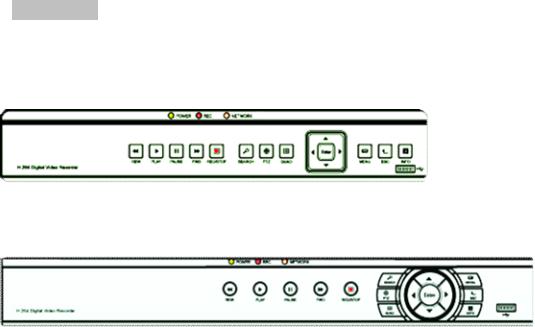
|
www.falconeye.su |
Руководство пользователя цифрового видеорегистратора |
|
Функции:
ØВысокопрофильный формат сжатия видеоH.264.
ØФормат сжатия звукаG.711.
ØГрафический интерфейс пользователяWindows, встроенная операционная система с обработкой данных в реальном масштабе времени.
ØСовмещение функцийDVR/NVR/HVR, поддержка аналогового входа, сетевой вход дляHD видео.
(данную функцию поддерживают не все модели, зависит от конкретного устройства).
ØМногофункциональная работа в реальном времени(предварительный просмотр, воспроизведение, резервное копирование, наблюдение по сети, мониторинг).
ØПоддержка двух потоков(основной поток – для локального хранения, второстепенный – для сетевой передачи).
ØПоддержка удаленного доступа, функции Р2Р, простое удаленное управление.
ØПоддержка расширений3G и Wi-Fi (опция).
ØПоддержка просмотра через мобильный телефон(Android iPhone iPad Blackberry Windows Phone)
ØВыход VGA и HDMI при разрешении 1920×1080P.
ØПоддержка различных браузеров, в т.ч., Windows IEFirefoxChromeSafari.
ØПоддержка интерфейса резервного копированияUSB 2.0, запись CD/DVD, обновление программного обеспечения, работа с мышью.
ØПоддержка меню на разных языках.
ØПоддержка программного обеспеченияCMS.
1.3 Инструкции по работе с передней панелью
 Примечание: Изображения в этом руководстве представлены исключительно в ознакомительных целях, в качестве стандарта используйте устройство.
4-8-16 каналов
8-16 каналов
7
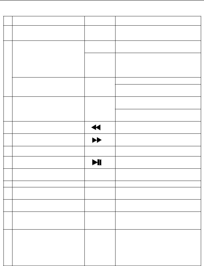
|
www.falconeye.su |
Руководство пользователя цифрового видеорегистратора |
|||||
1.3.1 Функции кнопок передней панели. |
||||||
|
№ |
Название кнопки |
Обозначение |
Функция |
|||
|
1 |
Кнопка |
главного меню |
MENU |
Вход в установки главного меню |
||
|
< > |
Для перемещения вверх и вниз по |
|||||
|
установкам в меню |
||||||
|
Кнопка направления |
Для перемещения влево и вправо по |
|||||
|
установкам в меню |
||||||
|
< > |
||||||
|
2 |
Воспроизведение на разной скорости (x2/ |
|||||
|
x4/ x8/ x16) |
||||||
|
Главное меню/кнопка |
Подтвердить |
|||||
|
ENTER |
Вход в главное меню или следующее |
|||||
|
подтверждения |
||||||
|
подменю |
||||||
|
Возврат в предыдущее меню или выход из |
||||||
|
3 |
Кнопка |
отмены |
ESC |
меню |
||
|
Возврат к наблюдению в реальном |
||||||
|
времени при воспроизведении |
||||||
|
4 |
Просмотр в обратном направлении |
Воспроизведение в обратном |
||||
|
направлении |
||||||
|
5 |
Ускоренное |
воспроизведение |
Воспроизведение на одной из скоростей |
|||
|
или на нормальной скорости |
||||||
|
6 |
Остановка |
воспроизведения |
● |
Остановка воспроизведения |
||
|
7 |
Кнопка |
воспроизведения/паузы |
Воспроизвести запись или приостановить |
|||
|
процесс воспроизведения |
||||||
|
8 |
Кнопка |
записи |
REC |
Индикатор горит при выполнении записи |
||
|
видеорегистратором |
||||||
|
9 |
Кнопка |
поиска записи |
SEARCH |
Поиск записанных файлов |
||
|
10 |
Кнопка управления PTZ |
PTZ |
Вход в установки PTZ |
|||
|
(панорама/наклон/зум), управление PTZ |
||||||
|
11 |
Информация системы |
INFO |
Вход в меню системной информации |
|||
|
видеорегистратора |
||||||
|
12 |
Кнопка Quad |
QUAD |
Переключение между одним и |
|||
|
несколькими каналами |
||||||
|
Видеорегистратор выполняет запись, |
||||||
|
Светодиодные индикаторы |
REC |
индикатор горит ярким светом |
||||
|
Если индикатор горит ярко, сетевые |
||||||
|
13 |
REC/NETWORK/POWER |
NETWORK |
||||
|
соединения в норме. В противном случае |
||||||
|
(ЗАПИСЬ/СЕТЬ/ВКЛ) |
POWER |
|||||
|
индикатор горит приглушенно. |
||||||
|
Индикатор питания |
||||||
|
8 |
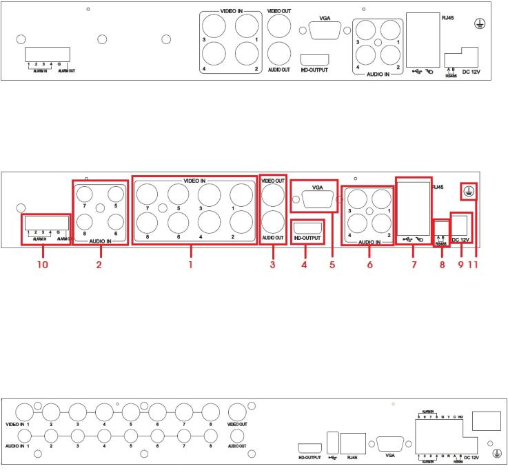
|
www.falconeye.su |
Руководство пользователя цифрового видеорегистратора |
|
1.4 Инструкции по работе с задней панелью
1.4.1 Панель четырехканального цифрового видеорегистратора
1.4.1 Панель восьмиканального цифрового видеорегистратора
Панель восьмиканального цифрового видеорегистратора 1
|
Панель восьмиканального цифрового видеорегистратора (1) |
|||||
|
(1) |
вход видео |
(2) |
вход |
звука |
(3) выход видео/звука (4) порт HDMI |
|
(5) |
порт VGA |
(6) |
вход |
звука |
(7) сетевой интерфейс/портUSB (8) интерфейс RS485 |
(9)питание (10) вход/выход сигнализации (11) заземляющее соединение
Панель восьмиканального цифрового видеорегистратора (2)
9
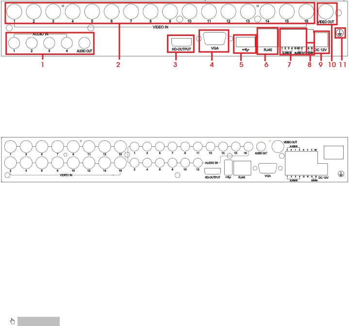
|
www.falconeye.su |
Руководство пользователя цифрового видеорегистратора |
|
1.4.3 Панель шестнадцатиканального цифрового видеорегистратора
|
Панель шестнадцатиканального цифрового видеорегистратора (1) |
||||
|
(1) |
Вход/выход звука (2) Вход |
видео |
(3) Порт HDMI |
(4) Порт VGA |
|
(5) |
USB-интерфейс (6) Сетевой интерфейс |
(7) Вход/выход сигнализации (8) Интерфейс RS485 |
||
|
(9) |
Питание (10) Выход видео |
(11) Заземляющее соединение |
Панель шестнадцатиканального цифрового видеорегистратора (2)
1.5Пульт дистанционного управления цифровым видеорегистратором
Впульте используется две батареи размером ;АААустановка батарей выполняется следующим образом:
Шаг 1: Откройте крышку отсека для батарей пульта дистанционного управления. Шаг 2: Установите батареи с учетом полюсов (+ и -).
Шаг 3: Установите крышку батарейного отсека обратно.
Примечание: Если пульт не работает, проверьте следующее:
1.Проверьте полярность батарей.
2.Проверьте оставшийся заряд батарей.
3.Убедитесь, что датчик контроллера ИК не закрыт
Если пульт все еще не работает, попробуйте заменить его или свяжитесь со своим поставщиком
Ниже приведен интерфейс пульта ДУ:
10
![]()
|
www.falconeye.su |
Руководство |
пользователя |
цифрового видеорегистратора |
|
|
Номер п/п |
Название кнопки |
Функция |
||
|
Аналогична кнопке |
||||
|
1 |
POWER |
включения на передней |
||
|
панели |
||||
|
2 |
SEARCH |
Вход в режим |
||
|
воспроизведения |
||||
|
Ввод кода входа/номер |
||||
|
входа/переключение между |
||||
|
3 |
Кнопки ввода |
количеством каналов «10+» |
||
|
цифр |
(нажимайте 0 и от 1 до 6, |
|||
|
чтобы переключаться между |
||||
|
каналами от 11 до 16) |
||||
|
4 |
QUAD |
Аналогична функции кнопки |
||
|
QUAD на передней панели |
||||
|
Кнопка |
Аналогична кнопке |
|||
|
5 |
направления передней |
|||
|
направления |
||||
|
панели |
||||
|
6 |
MUTE |
Отключение звука |
||
|
7 |
INFO |
Вход в информационное |
||
|
меню системы |
||||
|
8 |
Предыдущий файл |
|||
|
Следующий файл |
||||
|
Просмотр в обратном |
||||
|
9 |
направлении |
|||
|
Ускоренное воспроизведение |
||||
|
10 |
Запись |
|||
|
Остановить воспроизведение |
||||
|
11 |
Кнопка |
|||
|
воспроизведения/паузы |
||||
|
12 |
PTZ |
Кнопка управления PTZ |
||
Раздел 2 — Установка цифрового видеорегистратора |
Примечание: После покупки цифрового видеорегистратора проверьте устройство и
аксессуары.
Отключайте питание перед подключением к другим устройствам. Запрещается выполнять «горячее» включение/выключение
11
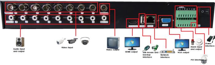
|
www.falconeye.su |
Руководство пользователя цифрового видеорегистратора |
|
2.1 Установка жесткого диска
1.Запрещено извлекать жесткий диск при включенном питании цифрового видеорегистратора.
2.Ослабьте болты с правой стороны при выключенном питании видеорегистратора, снимите верхнюю крышку.
|
3. Подсоедините кабели передачи данных и кабели |
питания жесткого диска к материнской плате |
|
цифрового видеорегистратора. Зафиксируйте жесткий диск на держателе при помощи четырех винтов. |
|
|
4. Если у пользователя высокие требования к жесткому диску, |
советуем использовать специальный |
жесткий диск, обеспечивающий повышенную безопасность и защиту.
2.2Подсоединение камер и мониторов
2.2.1Соедините видеовыход камеры с видеовходом цифрового видеорегистраторак белем с разъемами BNC, затем видеовыход видеорегистратора с монитором черезVGA или HDMI кабель. Если камера поддерживает управлениеPTZ, соедините кабель камеры с видео входом видеорегистратора через интерфейс RS-485.
2.2.2Например, подсоединение восьмиканального цифрового видеорегистратора выполняется следующим образом:
.
|
Audio input and output |
Вход и выход аудио |
|
Video input |
Вход видео |
|
Video output |
Выход видео |
|
HDMI output |
Выход HDMI |
|
USB mouse and backup interface |
Интерфейс для мыши и резервного копирования |
|
Network interface |
Сетевой интерфейс |
|
VGA output |
Выход VGA |
|
Alarm input and output |
Выход и выход сигнализации |
|
PTZ interface |
Интерфейс PTZ |
|
Power interface |
Интерфейс питания |
Рис. 2.1 Схема соединений системы
12

|
www.falconeye.su |
Руководство пользователя цифрового видеорегистратора |
|
2.3 Подключение питания
Рекомендуем использовать для данного цифрового видеорегистратора адаптер питания. После подключения рекомендуем убедиться, что входы/выходы звукового и видеоинтерфейса подключены должным образом.
Раздел 3 — Основные инструкции по эксплуатации
3.1 Включение/выключение питания цифрового видеорегистратора
Примечание:
1.Перед включением питания видеорегистратора убедитесь, что все соединения выполнены надлежащим образом.
2.Чтобы продлить срок жизни видеорегистратора, необходимо правильно выполнять процедуры включения и выключения питания
3.Для защиты источника питания при нормальных условиях рекомендуется использовать устройство бесперебойного питания.
3.1.1 Включение питания видеорегистратора
Подключите блок питания к электрической сети и включите переключатель подачи электропитания. Яркое свечение индикатора питания обозначает, что цифровой видеорегистратор включен. После запуска вы услышите короткий звуковой сигнал. Установка видеовыхода по умолчанию – режимы многоэкранного выхода. Если время запуска не превышает времени настройки , видеофункция синхронизации видеозаписи запускается автоматически. В этом случае индикатор соответствующего канала светится и цифровой видеорегистратор работает нормально.
3.1.2 Выключение питания видеорегистратора
Существует три способа выключения цифрового видеорегистратора. Вариант 1: Стандартное (программное) выключение
Войдите в главное меню, выберите «Menu» (Меню) → «Shutdown» (Выключение) 2: Выключение вручную Нажмите выключатель питания, извлеките сетевую вилку из блока питания
3.2 Вход в систему цифрового видеорегистратора
При загрузке видеорегистратора пользователь должен войти в ,системупри этом система предоставляет соответствующую функцию в зависимости от полномочий пользователя. Существует 3
типа полномочий: Admin (Администратор), Guest (Гость) и Default (По умолчанию). Если имя пользователя по умолчанию Admin, пароль вводить не требуется. Администратор – пользователь высшего уровня. Гость и по умолчанию – это заводские установки для обычного пользователя.
13
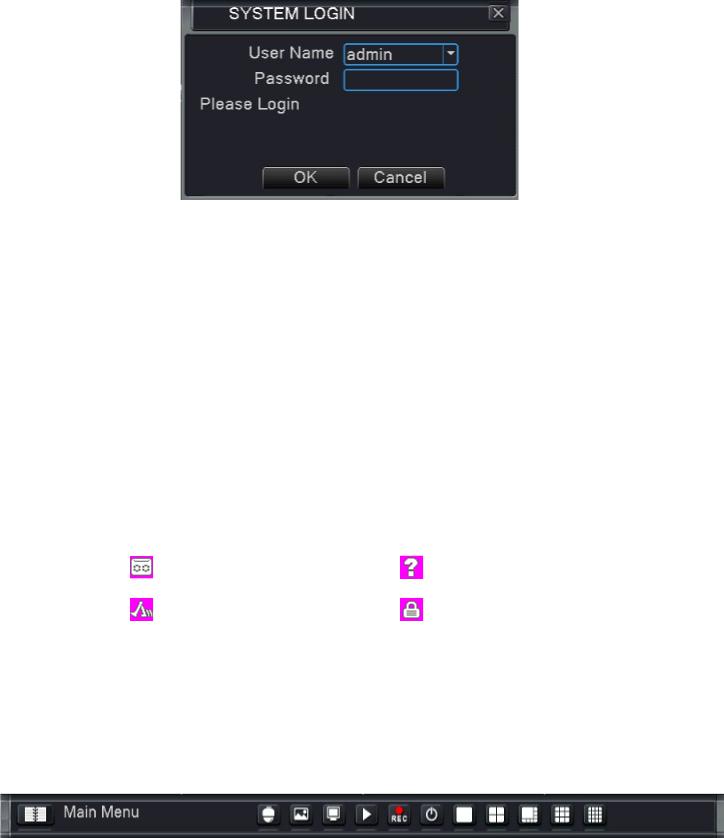
|
www.falconeye.su |
Руководство пользователя цифрового видеорегистратора |
|
Рис. 3.1
Защита паролем: Пароль не требуется, для первого входа просто нажмите «ОК».
После установки пароля, если неправильный пароль вводится три раза, запускается сигнализация. Если пароль вводится неправильно5 раз подряд, учетная запись блокируется. (Блокировка учетной записи снимается автоматически после перезагрузки или через полчаса)
В целях безопасности системы рекомендуем изменить ваш пароль после первого входа.
3.3 Предварительный обзор
Переключение между режимами просмотра канала происходит путем двойного клика левой кнопкой мыши на выбранном канале. Необходимый канал или режим вывода каналов на дисплее можно настроить путем выбора одной из иконок, расположенных в правой части контекстного меню.
Дата, время и название канала системы отображаются во всех просматриваемых окнах . Во всех окнах также отображается видео, полученное путем видеонаблюдения, и статус сигнализации.
|
1 |
Состояние записи |
3 |
Пропадание |
||
|
видеосигнала |
|||||
|
2 |
Обнаружение |
4 |
Блокировка |
||
|
движения |
камеры |
||||
3.4Контекстное меню
Врежиме предварительного обзора нажатие правой кнопки мыши вызывает контекстное меню в нижней части монитора, как на следующем изображении:
Рис. 3.2 Контекстное меню
Контекстное меню включает в себя следующие функции: главное меню, управление PTZ, настройка цвета, настройка вывода, воспроизведение, режим записи и выход.
14
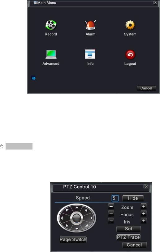
|
www.falconeye.su |
Руководство пользователя цифрового видеорегистратора |
|
3.4.1 Главное меню
Главное меню: Доступ к главному меню для регулировки всех настроек При входе в систему это меню отображается следующим образом:
Рис. 3.3 Главное меню
3.4.2 Управление панорамой/наклоном/зумом (PTZ)
Управление PTZ: Функции, которые включают управление направлением панорамы/наклона/зума, их шаг, масштабирование, фокус, диафрагма, настройка, просмотр между точками, наблюдение по маршруту, сканирование границ, переключение на вспомогательное устройство, перемещение по маршруту и пр.
Примечание:
1.Перед началом работы убедитесь, что линия декодера 485+,485line должным образом соединена
слинией 485+,485видеорегистратора.
2.Перед началом работы нажмитеmenu (меню)-> system (система)-> PTZ config (настройка PTZ), чтобы установить параметры PTZ.
3.Функции PTZ определяются протоколами PTZ.
Рис. 3.4: интерфейс управления PTZ
15
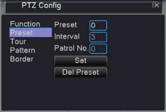
|
www.falconeye.su |
Руководство пользователя цифрового видеорегистратора |
|
Speed : Установка диапазона поворота PTZ, диапазон по умолчанию – 1-8Zoom : Нажимайте / , чтобы настроить масштаб съемки.
Focus : Нажимайте / , чтобы настроить фокус камер.Iris : Нажимайте / , чтобы настроить диафрагму камер.
Hide : После нажатия на эту опцию текущий интерфейс будет временно скрыт.Direction control : Управление поворотом PTZ. Поддерживается 8 направлений поворота.PTZ Trace : Канал изображения отображается во весь экран. Управление поворотом PTZ
осуществляется путем нажатия левой кнопки мыши. Настройка масштаба камер осуществляется путем нажатия левой кнопки мыши и вращения мыши.
Set : Вход в рабочее меню функций.
Page switch : Переключение между разными страницами установок. Нажмите, чтобы войти в настройки дополнительных функций
Рис. 3.5: Заданные настройки
[Special functions:] – особые функции
1. Настройка предустановки
Установите местонахождение предустановки, вызовите точки предустановки, PTZ автоматически переключается в положение настройки.
(1) Чтобы задать предустановки:
Установите местоположение предустановки следующим образом:
Шаг 1: на рис. 3.4 нажмите кнопку направления; камера переходит в заданное положение. Для входа на меню рис. 3.5 нажмите кнопку «Set» (Установить).
Шаг 2: Нажмите кнопку предустановки, запишите заданные точки в полях ввода
Шаг 3: нажмите кнопку «Set» (Установить), вернитесь к изображению 3.4, завершите настройку, соответствующую заданным точкам и положению.
Чтобы удалить заданные настройки: Введите заданные предустановки и нажмите кнопку Del Preset для их удаления.
(2) Задайте точки предустановки
На рис. 3.4 нажмите кнопку «Page Switch» (Переключение страниц), войдите в интерфейс управления PTZ, как показано на рис. 3.6. В поле ввода запишите заданные точки , далее нажмите кнопку, чтобы задать настройки (Preset). PTZ повернется в соответствующую заданную точку.
16
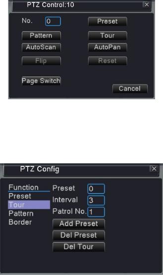
|
www.falconeye.su |
Руководство пользователя цифрового видеорегистратора |
|
Рис. 3.6: Управления PTZ
2. Перемещение между точками
Траектория перемещения, определенная предустановленными точками, называются маршрутом между точками (Тур).
Рис. 3.7 Настройки перемещения между точками
(1) Настройки маршрута между точками.
Траектория перемещения определяется несколькими предустановленными точками. Процедура установки выглядит следующим образом:
Шаг 1: На рис. 3.4 клавиша направления повернет PTZ в сторону обозначенного положения; нажмите кнопку «Set»(Установки), чтобы перейти к меню, как на рис. 3.7,
Шаг 2: Нажмите кнопку «Tour»(Маршрут), а затем введите нужное значение в поля «Patrol No.» (№ патрулирования) и «Preset Points» (Предустановленные точки), нажмите кнопку «Add Preset Points» (Добавить предустановленные точки) и завершите установку (вы также можете добавлять и удалять уже настроенные линии перемещения)
Шаг 3: Повторяйте шаги 1 и 2 до тех пор, пока не настроите маршрут
Удалить предустановки: Введите заданное значение в пустое поле, нажмите кнопку «Del Preset» (Удалить предуст.), а затем удалите заданные положения.
Удалить маршрут: Введите номер маршрута, нажмите кнопку «Del Tour»(Удалить маршрут), а затем удалите установленные линии перемещения.
(2) Вызов маршрута
На Рис. 3.4, нажмите кнопку «Page Switch»(Переключение страниц), войдите в меню контроля PTZ, как
17
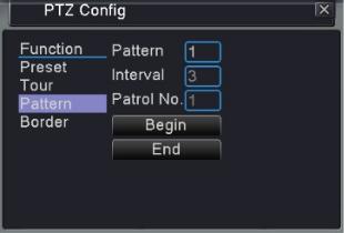
|
www.falconeye.su |
Руководство пользователя цифрового видеорегистратора |
|
показано на Рис. 3.6. Введите количество перемещений в поле, а затем нажмите кнопку Tour. PTZ начнет работать перемещаться по маршруту. Нажмите кнопку «Stop»для остановки перемещения.
3. Осмотр (схема)
PTZ также может работать на предустановленной линии осмотра в непрерывном режиме.
Рис. 3.8 Настройки осмотра
(1) Настройка осмотра Выполните следующее:
Шаг 1: На картинке 3.4, нажмите кнопку «Setup»(Настройка), войдите в меню, как на рис. 3.8; Шаг 2: Нажмите кнопку «Pattern»(Схема), затем введите нужное значение в поле сканирования;
Шаг 3: Нажмите кнопку «Begin»(Начать), войдите в меню, как на рис. 3.4. Здесь вы можете настроить следующие значения: масштабирование, фокус, диафрагму, направление и т.д. Нажмите кнопку «Setup», чтобы вернуться к рис. 3.8
Шаг 4: Нажмите кнопку «End» (Завершить), чтобы закончить установку. Нажмите правой кнопкой мыши для выхода.
(2) Запуск осмотра
На Рис. 3.4, нажмите кнопку «Page Switch»(Переключение страниц), войдите в меню контроля PTZ, как показано на рис. 3.6. Введите количество осмотров в поле, затем нажмите кнопку «Pattern»(Схема), и поворотное устройство PTZ (панорама/наклон/зум) начнет работать на линии (Переключение страниц). Нажмите кнопку «Stop»для остановки.
4. Периферийный осмотр (границы)
Установите линию горизонтально и запустите осмотр. Поворотное устройство PTZ будет повторять операцию по маршруту.
18
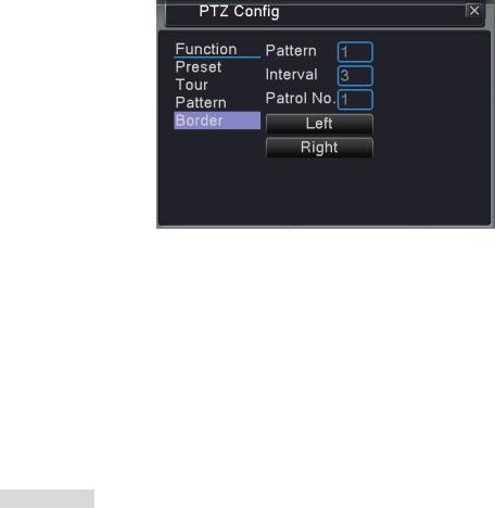
|
www.falconeye.su |
Руководство пользователя цифрового видеорегистратора |
|
Рис. 3.9 Настройки периферийного осмотра
(1) Настройка периферийного осмотра
Настроить периферийный осмотр PTZ, выполнив следующие шаги:
Шаг 1: На Рис. 3.4, нажмите кнопку «Direction» (Направление) для поворота PTZ в заданном направлении, затем нажмите кнопку «Setup»(Настройка), войдите в Рис. 3.9, выберете левую границу, вернитесь к рисунку 3.4;
Шаг 2: Нажмите стрелочки направления для настройки направления PTZ, нажмите кнопку «Setup», войдите в меню, как на рис. 3.9, затем выберите правую границу, вернитесь к рис. 3.4
Шаг 3: Завершите установку, т.е. положения правой и левой границ.
 Примечание: Когда осмотры слева и справа производятся на одной горизонтальной линии, поворотное устройство PTZ будет поочередно переходить от осмотра слева к осмотру справа по линии в обратном направлении.
Когда осмотры слева и справа производятся не на одной горизонтальной ,линииPTZ рассчитает конец горизонтальной линии, которая соединяет осмотры справа и слева, и поочередно переходить от осмотра слева к осмотру справа по линии в обратном направлении.
(2) Запуск периферийного осмотра
На Рис. 3.4, нажмите кнопку «Page Switch»(Переключение страниц) и зайдите в меню настроек PTZ (панорама/наклон/зум), как показано на Рис. 3.6.
Введите номер осмотра в поле и нажмите кнопку «Scan» (Осмотр). Поворотное устройство начнет работать на линии осмотра. Нажмите кнопку «Stop»для остановки.
5. Горизонтальное вращение
Нажмите кнопку «Horizontally Rotating» (Горизонтальное вращение), поворотное устройство PTZ начнет вращаться горизонтально (относительно начальной позиции). Нажмите кнопку «Stop»для остановки.
6. Вращение
Нажмите на кнопку Horizontal Rotating, PTZ начнет вращаться по кругу.
7. Сброс
PTZ перезапускается, все данные обнуляются.
19
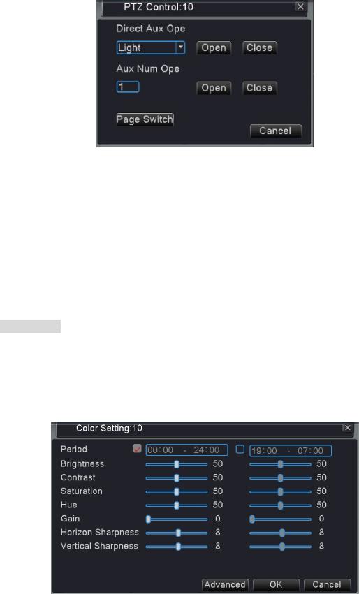
|
www.falconeye.su |
Руководство пользователя цифрового видеорегистратора |
|
8. Переключение страниц
На Рис. 3.6 нажмите кнопку «Page Switch»(Переключение страниц), перейдите к меню, как на рис. 3.10, настройте дополнительные функции. Вспомогательный номер соответствует вспомогательному выключателю на декодере.
Рис. 3.10 Вспомогательные функции
Intuitive Auxiliary Operation выберите вспомогательное оборудование, нажмите кнопку Open (Открыть) или Close (Закрыть), переключите управление;
Auxiliary Number Операция соответствующего вспомогательного переключателя, координированного с PTZ;
Page Switch На Рис.3.10, нажмите кнопку «Page Switch»(Переключение страниц), войдите в основное меню PTZ, как на рис. 3.4. Навигация в меню производится кнопками управления меню
3.4.3 Настройка цвета
 Примечание: Настройка цвета применяется только для гибридного режима(HVR)/DVR) и только для аналоговых каналов.
Настойка цвета: Настройте параметры текущего канала Для входа в интерфейс вы можете использовать контекстное . менюПараметры изображения
включают: Яркость, контрастность, насыщенность, оттенок, усиление, резкость горизонта, вертикальная четкость. Вы можете установить различные параметры для разного времени.
Рис. 3.11 Настройки цвета
20
![]()
|
www.falconeye.su |
Руководство пользователя цифрового видеорегистратора |
|
3.4.4 Регулировка вывода изображения
Регулировка вывода изображения: Отрегулируйте параметры
Вы можете использовать контекстное меню или войти в главное меню, выберите «Management tools» (инструменты управления) → «Output adjust» (Регулировка выхода)
Рис. 3.12 Регулировка выхода
3.4.5 Воспроизведение
Воспроизведение: Войдите в режим воспроизведения, настройте поиск по записи, воспроизведение записи, хранение видеофайлов
21
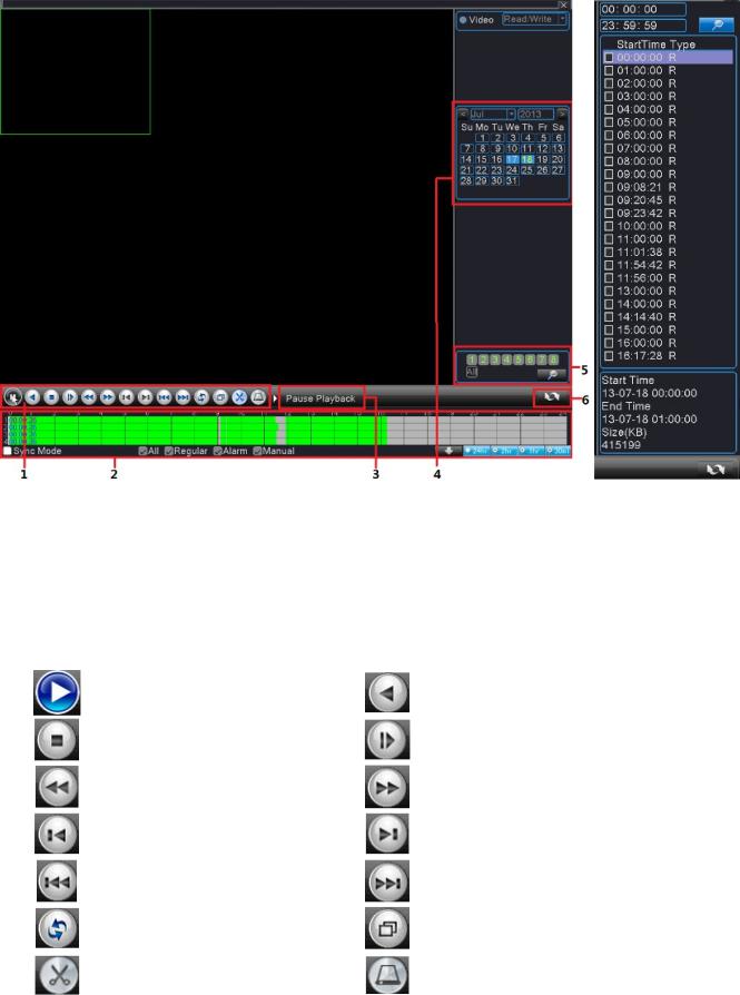
|
www.falconeye.su |
Руководство пользователя цифрового видеорегистратора |
|
Рис. 3.13 Воспроизведение Рис 3.14 Список файлов
1. Управление воспроизведением 2. Запись время и состояния файлов3. Советы по эксплуатации
|
4. Дата |
5. Поиск файлов |
6.Переключиться |
на информацию по записи файлов |
|||
|
Детали управления воспроизведением |
||||||
|
Клавиша |
Функции |
Клавиша |
Функции |
|||
|
Воспроизвести/Пауза |
Воспроизведение назад |
|||||
|
Стоп |
Замедленное воспроизведение |
|||||
|
Перемотка назад |
Перемотка вперед |
|||||
|
Предыдущий кадр |
Следующий кадр |
|||||
|
Предыдущий файл |
Следующий файл |
|||||
|
Повторить воспроизведение |
Полный экран |
|||||
|
Редактировать |
Резервная копия записи |
|||||
22
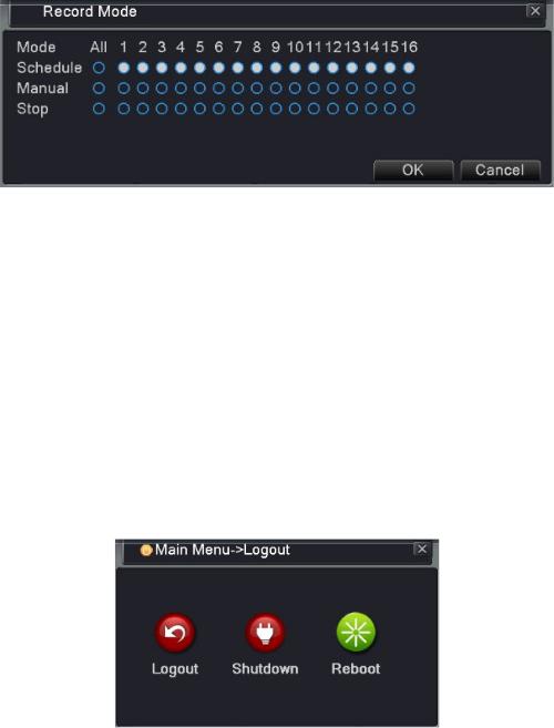
|
www.falconeye.su |
Руководство пользователя цифрового видеорегистратора |
|
3.4.6 Режим записи
Режим записи: Проверьте текущее состояние записи каналов Для входа в интерфейс управления записью вы можете использовать контекстное меню или войти в
главное меню и выбрать Recording Function (функция записи) → Recording «Set»(настройка записи).
Рис. 3.15 Запись
Вы можете проверить текущее состояние каналов: ○ означает, что запись не идет, ● означает, что запись идет.
Schedule : Запись по расписанию.
Manual: После нажатия кнопки «All» (Все) соответствующий канал начнет запись независимо от его текущего статуса.
Stop : После нажатия кнопки«Stop»(Остановить) соответствующий канал прекратит запись независимо от его текущего статуса.
3.4.7 Выход
Выход: Выход, выключение системы или перезагрузка.
Вы можете использовать контекстное меню или войти в главное меню →Logout (Выход)
Рис. 3.16 Выход/Выключение/Перезагрузка видеорегистратора
Logout Выйдите из меню. Введите пароль при следующем входе.
Shut down Выключите систему. Выключите питание. После нажатия кнопки «Shutdown» (Выключение) появляется подсказка. Через три секунды система выключается. Отмена на полпути невозможна.
Reboot Выключите систему. Перезагрузите систему.
23
|
www.falconeye.su |
Руководство пользователя цифрового видеорегистратора |
|
Глава 4 – Главное Меню
4.1 Управление Главным меню
|
Главное |
Подменю |
Функция |
|
|
меню |
|||
|
Конфигурация |
Установка параметров записи, таких как тип записи, время |
||
|
записи и т.д. |
|||
|
Запись |
Воспроизведение |
Поиск записи, воспроизведение записи, хранение записанных |
|
|
файлов |
|||
|
Резервное |
Обнаружение резервного оборудования, форматирование |
||
|
копирование |
резервного оборудования, резервных файлов |
||
|
Обнаружение |
Установка канала обнаружения движения, чувствительности, |
||
|
область, параметров соединения: вывод сигнализации, |
|||
|
движения |
|||
|
подсказки на экране, запись, PTZ, патрулирование и т.д. |
|||
|
Установка характеристик ослабления канала, чувствительности, |
|||
|
Ослабление видео |
параметров соединения, вывод сигнализации, подсказки на |
||
|
экране, запись, PTZ, патрулирование и т.д. |
|||
|
Установить канал потери видео, параметры соединения: вывод |
|||
|
Потеря видео |
сигнализации, подсказок на экране, запись, PTZ, |
||
|
патрулирование, и т.д. |
|||
|
Установка канала входа сигнала, тип устройства, параметры |
|||
|
Вход сигнализации |
соединения, вывод сигнализации, подсказки на экране, запись, |
||
|
Сигнализация |
PTZ, патрулирование, звуковой сигнал, загрузка по электронной |
||
|
почте и FTP |
|||
|
Выход сигнализации |
Установка режима сигнализации: конфигурация, ручной режим, |
||
|
остановка, т.д. |
|||
|
Обработка |
Нет жесткого диска, ошибка жесткого диска, объема жесткого |
||
|
диска не достаточно, сбой сети, IP конфликт, параметры |
|||
|
исключений |
|||
|
соединения: подсказки на экране или звуковой сигнал. |
|||
|
Установка правила алгоритма: показать траекторию, |
|||
|
чувствительность, минимальный пиксель, режим оповещения; |
|||
|
Умный анализ |
установка параметров соединения, вывод сигнализации, запись, |
||
|
PTZ, маршрут, звуковая сигнализация, электронная почта и |
|||
|
загрузка по FTP. |
|||
|
Установка даты системы, формата даты, языка, круглосуточной |
|||
|
Общая |
работы жесткого диска, номера устройства, формата видео, |
||
|
конфигурация |
режима вывода, перехода на летнее время, продолжительности |
||
|
Конфигураци |
действия. |
||
|
я системы |
Установка параметров основного потока и субпотока: режим |
||
|
Кодированная |
кода, разрешение, кадр, контроль кодового потока, тип качества |
||
|
конфигурация |
изображения, значение кодового потока, кадр между значением, |
||
|
активация видео/аудио. |
24
 Loading…