
ИНСТРУКЦИЯ
ХРОМАТОГРАФЫ ЖИДКОСТНЫЕ Agilent 1100, Agilent 1200
Методика поверки
Москва 2006 г.
с_.
Настоящая инструкция распространяется на жидкостные хроматографы Agilent 1100, Agilent 1200 со спектрофотометрическим с измененяемой длиной волны, многоволновым спектрофотометрическим, на диодной матрице, рефрактометрическим и флуориметрическим детекторами и устанавливает и устанавливает методику их первичной и периодической поверок.
Межповерочный интервал 1 год.
1 ОПЕРАЦИИ ПОВЕРКИ
-
1.1 При проведении поверки должны выполняться операции, указанные в таблице 1.
Таблица 1
|
Наименование операции |
Номер пункта методических указаний |
Обязательное проведение операции |
|
|
при эксплуата ции |
После ремонта |
||
|
Внешний осмотр |
4.1. |
да |
да |
|
Опробование |
4.2. |
да |
да |
|
— определение уровня флуктуационных шумов нулевого сигнала |
4.2.1. |
да |
да |
|
— определение дрейфа нулевого сигнала |
4.2.2. |
да |
да |
|
— определение отношения сигнал/шум по Рамановскому спектру воды для флуоримет-рического детектора |
4.2.3. |
да |
да |
|
— определение предела детектирования |
4.2.4. |
да |
да |
|
Определение метрологических характеристик: |
4.3. |
да |
да |
|
— определение относительного среднего квадратического отклонения выходного сигнала |
4.3.1,- 4.3.4. |
да |
да |
|
— определение относительного изменения выходного сигнала за 8 часов непрерыв- |
ной работы ____________________4.3.5.- 4.3.6.____.________да__________, да ___
2 СРЕДСТВА ПОВЕРКИ, РЕАКТИВЫ И МАТЕРИАЛЫ
Контрольные вещества:
-ГСО 7895-2001 состава раствора кофеина в воде;
— аттестованные растворы антрацена в ацетонитриле.
Ацетонитрил для жидкостной хроматографии ТУ 6-09-14-2167-84. Вода дистиллированная по ГОСТ 6709-72. «Г
Колонка Hypersil ODS 125×4,0 мм.
Допускается применять другие средства поверки, метрологические характеристики которых соответствуют указанным в настоящей инструкции.
3. УСЛОВИЯ ПОВЕРКИ И ПОДГОТОВКА К НЕЙ
3.1 При проведении поверки соблюдают следующие условия:
|
20 ±5 84- 106.7 |
|
— относительная влажность воздуха, % |
30-90 |
|
— напряжение переменного тока, В |
220 ± 22 |
|
— частота сети, Гц |
50 ± 1 |
-
3.2 Подготовительные работы выполняют в соответствии с инструкцией по эксплуатации хроматографа.
При использовании системы Agilent ChemStation поверка хроматографа выполняется автоматически. Установку режимных параметров, проведение операций поверки и обработку результатов выполняют через функцию «Verification».
-
3.3 Перед проведением поверки готовят контрольные смеси, назначение и содержание анализируемых компонентов в которых приведено в таблице 2. Относительная погрешность аттестации не более 10%.

Таблица 2
Контрольный раствор
Массовая концентрация мг/дм3
Объем пробы, мкл
Элюент
Скорость потока элюента, см3/мин
—
Детектор
Кофеин—вода
0,125 /<?
5
Ацетонитрил : вода 4:1
и
Спектрофотометрический с измененяе-мой длиной волны
Многоволновой спектрофотометрический
На диодной матрице
Кофеин-вода
1,25
1
Ацетонитрил : вода
1
Рефрактометриче
ский
4 ПРОВЕДЕНИЕ ПОВЕРКИ
-
4.1 Внешний осмотр
При внешнем осмотре установливают:
-
— соответствие комплектности хроматографа паспортным данным:
-
— четкость маркировки;
-
— исправность механизмов и крепежных деталей.
-
4.2 Опробование
При опробовании проводят определение уровня флуктуационных шумов, дрейфа нулевого сигнала, отношения сигнал/шум по Рамановскому спектру воды для флуори-метрического детектора и предела детектирования для остальных детекторов.
-
4.2.1 Уровень флуктуационных шумов и дрейф нулевого сигнала определяют при условиях, указанных в таблице 3, после выхода хроматографа на режим (время выхода на режим для каждого детектора установлено в инструкции по эксплуатации). Уровень флуктуационных шумов и дрейф нулевого сигнала измеряют в динамическом режиме в течение 30 мин. В качестве элюента используют воду.
Уровень флуктуационных шумов нулевого сигнала (ДХ) принимают равным амплитуде (h) повторяющихся колебаний нулевого сигнала с периодом не более 20 секунд.
Таблица 3
|
Детектор |
||
|
Спектрофотометрический с измене-няемой длиной волны; многоволновой спектрофотометрический; на диодной матрице |
Рефрактометрический |
|
|
Элюент |
Вода |
Вода |
|
Скорость потока элюента, см’/мин |
0,8 |
1 |
|
Длина волны, нм |
254 |
— |
|
Постоянная |
2 |
4 |
времени, сек
-
4.2.2 При использовании системы Agilent ChemStation значения шума и дрейфа рассчитываются автоматически. Полученные значения не должны превышать значений, приведенных в таблице 4.
Таблица 4
|
Детектор |
Уровень флуктуа-цион-ных шумов нулевого сигнала (peak to peak) |
Дрейф нулевого сигнала |
|
Спектрофотометрический с изменяемой длиной волны — для 1100 7 — для 1200, 1200 SL |
4-10”5 е.о.п. 1,5-10”5 е.о.п. |
5-10-4 е.о.п./час 3-1 О’4 |
|
На диодной матрице, многоволновый спектрофотометрический
|
5,0-10”~ е.о.п. 2,0-10-5 е.о.п. 1,6-Ю-3 е.о.п. |
5,0-10^ е.о.п./час 2,0-10 J е.о.п./час 0,9-10~J е.о.п./час |
|
Рефрактометрический -для 1100 7 — для 1200 |
5,0-10-8 5,0-10-9 |
2-10_/ ед.рефр./час 2-10-7 ед.рефр./час |
-
4.2.3 Определение отношения сигнап/шум по Рамановскому спектру воды
Определения отношение сигнал/шум для флуориметрического детектора проводят согласно процедуре, описанной в Разделе 10 «Руководства по эксплуатации флуориметрического детектора» для хроматографа Agilent 1100 и Разделе 8 «Инструкции по сервисному обслуживанию» для хроматографа Agilent 1200 при длинах волн возбуждения 350 нм и эмиссии 392 нм.
Полученные значения должны быть не менее:
для Agilent 1100 series (вариант А платы FCF) 200:1
для остальных вариантов Agilent 1100 series 400:1
для Agilent 1200 series 500:1.
-
4.2.4 Определение предела детектирования
Предел детектирования определяют с использованием контрольных веществ и условий, указанных в таблице 2.
В хроматограф вводят пробу контрольного вещества, определяют высоту и ширину пика на половине его высоты (//0 5 )
Предел детектирования рассчитывают по формуле:
2-&X-G
MUH. J г -г г
Н ■ А: • р
|
где G V |
|
|
Au |
— ширина пика на половине высоты, мин; |
Дх — уровень флуктуационных шумов нулевого сигнала, определенный по п.4.2.1;
Н — высота пика контрольного вещества;
ЬХ и Н — измеряют в мм, условных единицах, мВ, либо в единицах, указанных в п.4.2.2.
Полученные результаты не должны превышать приведенных ниже значений предела детектирования:
|
Детектор спектрофотометрический с изменяемой длиной волны у/ Детектор на диодной матрице; |
1,5-10 9 г/см3 кофеина |
|
многоволновый спектрофотометрический детектор Детектор рефрактометрический |
2-10”9 г/см’’ кофеина 1 • 10-6 г/см“’ кофеина |
4.3 Определение метрологических характеристик
-
4.3.1 Определение относительного среднего квадратического отклонения выходных сигналов.
Измерения проводят после выхода хроматографа на режим. Условия выполнения измерений должны соответствовать приведенным в разделе 3.
-
4.3.2 Контрольный раствор (табл.З.) вводят в хроматограф не менее 6 раз, измеряют значения выходных сигналов (высот, площадей пиков и времен удерживания) и вычисляют их среднее арифметическое значение.
-
4.3.3 Относительное среднее квадратическое отклонение выходного сигнала рассчитывают по формуле
100 -АУ
х N п-1
где значение параметра выходного сигнала (площади пика, времени удержива-— ния). ,
4.3.4. Значения относительного среднего квадратического отклонения выходного сигнала (площади пика и времени удерживания), %, не должны превышать данных, приведенных в таблице 5.
Таблица 5
|
При автоматическом дозировании |
При ручном дозировании |
|||
|
по площа ди пика |
по времени удерживания |
по площа ди пика |
по времени удерживания |
|
|
Детектор спектрофотометрический с изменяемой длиной волны |
1 |
0,3 |
2 |
1 |
|
Детектор на диодной матрице, многоволновый спектрофотометрический детектор |
х/ 1 |
0,3 |
2 |
1 |
|
Детектор рефрактометрический |
2 |
0,3 |
3 |
0,3 |
|
Детектор флуориметрический |
2 |
0,3 |
4 |
0,3 |
-
4.3.5 Определение относительного изменения выходных сигналов за 8 часов непрерывной работы.
Условия измерения аналогичны, описанным в разделе 3. Проводят операции, описанные в п.4.3.2. Через 8 часов непрерывной работы повторяют измерения по п.4.3.2.
Относительное изменение выходного сигнала за 8 часов непрерывной работы хроматографа рассчитывают по формуле

Xt -X
-^—•100 X
-
4.3.6 Значения относительного изменения выходных сигналов (по площади пика) не должны превышать значений, приведенных в таблице 6.
Таблица 6
|
——————,——— ■ ——— При автоматическом дозировании |
При ручном дозировании |
|
|
Детектор спектрофотометрический с изменяемой длиной волны |
2 |
3 |
|
Детектор на диодной матрице, многоволновый спектрофотометрический детектор |
2 |
3 |
|
Детектор рефрактометрический |
5 |
6 |
|
Детектор флуориметрический |
э |
4 |
5 ОФОРМЛЕНИЕ РЕЗУЛЬТАТОВ ПОВЕРКИ
-
5.1 Результаты поверки хроматографа заносят в протокол.
При использовании системы Agilent ChemStation протоколы с результатами поверки распечатываются автоматически.
-
5.2 Положительные результаты поверки хроматографов оформляют выдачей свидетельства в соответствии с ПР 50.2.006.
-
5.3 Хроматографы, не удовлетворяющие требованиям настоящих рекомендаций, к эксплуатации не допускаются. Хроматографы изымаются из обращения. Свидетельство о поверке изымают и выдают извещение о непригодности с указанием причин в соответствии с ПР 50.2.006.
-
5.4 После ремонта хроматографы подвергают поверке.
Начальник сектора ФГУП «ВНИИМС»
Инженер ФГУП «ВНИИМС»

Т.О.Никифоров
О.Л.Рутенберг
Назначение
Хроматографы жидкостные Agilent 1100, Agilent 1200 предназначены для анализа широкого спектра веществ и могут применяться для контроля качества пищевых продуктов, лекарственных препаратов, определения загрязнителей питьевых поверхностных и сточных вод.
Описание
Хроматографы жидкостные Agilent 1100, Agilent 1200 (далее — хроматографы) комплектуются детекторами на диодной матрице, многоволновым спекгрофотометри-ческим, спектрофотометрическим с изменяемой длиной волны, флуориметрическими и рефрактометрическими детекторами, автосамплером или ручным дозатором, изократи-ческим и градиентными насосами.
Детектор на диодной матрице (1100, 1200 и 1200 SL) с программным обеспечением выполняет измерения с большой скоростью. Измерения могут быть проведены одновременно на нескольких длинах волн, что дает возможность судить о чистоте вещества.
Высокая разрешающая способность детектора обеспечивается диодной матрицей с 1024 диодами и устройством, программирующим ширину щели от 1 до 16 нм. Встроенный фильтр из оксида гольмия позволяет проверять точность установки длины волны.
Спектрофотометрический детектор предназначен для рутинных анализов веществ, имеющих поглощение в диапазоне 190-600 нм (1100, 1200 и 1200 SL) или 190-950 нм (1100, 1200 и 1200 SL). Программирование длины волны в зависимости от времени удерживания компонентов позволяет устанавливать для каждого из них оптимальную по чувствительности детектора длину волны. При использовании многоволновых детекторов измерения можно проводить одновременно на нескольких длинах волн.
Флуориметрический детектор (1100, 1200) дает возможность снять спектр флуоресценции, представляющий весь объем спектральной информации. Детектор способен регистрировать спектры флуоресценции параллельно с регистрацией хроматограмм. При работе в спектральном режиме детектор способен регистрировать хроматограмму одновременно на четырех длинах волн, что дает возможность определять содержание загрязняющих примесей на дополнительных длинах волн. Использование многоволновой регистрации повышает чувствительность и селективность при анализе сложных веществ.
Рефрактометрический детектор (1100, 1200) представляет собой дифференциальный рефрактометр, измеряющий отклонение луча света, обусловленное разницей показателей преломления жидкостей, находящихся в тех частях кюветы, которые используются для регистрации и для сравнения.
Усовершенствованная оптическая система, оснащенная специальным контролирующим температуру устройством, дает возможность подготовить детектор к работе за короткий промежуток времени. Детектор снабжен устройством автоматического обнуления сигнала и режимом автоматической промывки.
Автоматическая схема, регулирующая интенсивность света, гарантирует получение оптимальных эксплуатационных характеристик оптической системы. Рефрактометрический детектор снабжен системой самодиагностики.
Программное обеспечение детектора дает возможность проводить диагностику и устранять неисправности.
Хроматограф может работать как в изократическом, так и в градиентном режиме. Для этих целей хроматограф может комплектоваться либо изократическим насосом, либо градиентными насосами для создания двух- или четырехкомпонентного элюента, а так же градиентными двухканальными насосами 1200 SL. При работе с четырехкомпонентным градиентом хроматограф комплектуется системой вакуумной дегазации.
Ввод пробы может выполняться автоматически при помощи автосамплера или ручным дозатором. Кроме стандартных автосамплеров модификаций 1100, 1200 можно использовать модификацию с двойной петлей 1200 PS и высокопроизводительный ав-тосамплер 1200 SL. Конструкция автосамплера позволяет быстро отбирать без потерь пробы из виал (пробирок) разного объема, дозировать с хорошей воспроизводимостью пробы объемом от 0,1 мкл до 100 мкл. Система легко адаптируется для задач, требующих введение проб до 1500 мкл (например, полупрепаративная хроматография). Высокая воспроизводимость автосамплера достигается за счет применения шагового двигателя, обеспечивающего дозирование с дискретностью 7 нл.
В комплект хроматографа может входить блок термостатирования колонок, снабженный нагревателем Пельтье, и обеспечивающий стабильную работу при температурах до 80°С.
Контроль, за рабочими параметрами системы может выполняться переносным пультом управления как при автоматическом, так и при ручном режиме работы, а также для проверки состояния отдельных модулей системы.
Использование системы ChemStation позволяет полностью автоматизировать выполнение хроматографического анализа: задание и контроль режимных параметров, регистрацию выходных сигналов, обработку экспериментальных данных и выдачу протоколов с результатами анализа. Программное обеспечение ChemStation включает целый раздел, предусматривающий проверку метрологических характеристик хроматографа, сравнение их с заданными нормами и выдачу протоколов проверок. Для хроматографов Agilent 1100 используется 16-ти разрядное программное обеспечение; для хроматографов Agilent 1200 — 32-ух разрядное.
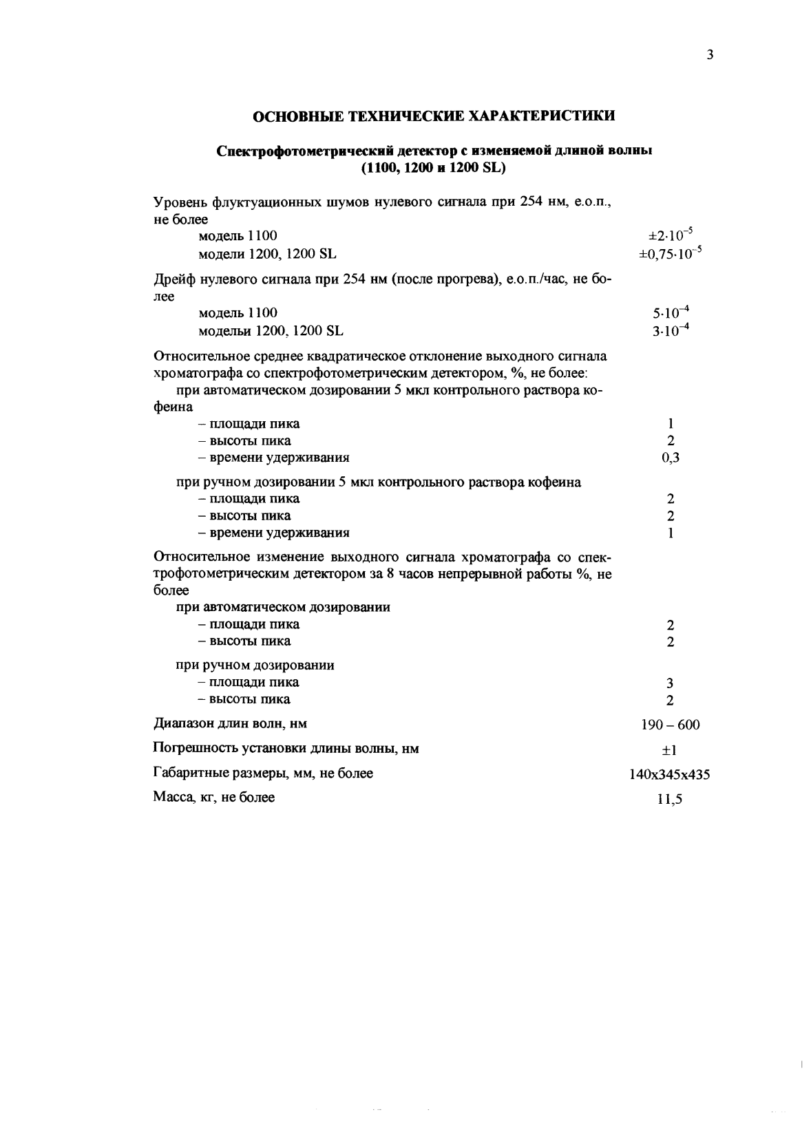
Спектрофотометрический детектор с изменяемой длиной волны
(1100,1200 и 1200 SL)
Уровень флуктуационных шумов нулевого сигнала при 254 нм, е.о.п., не более
модель 1100 ±210-3
модели 1200, 1200 SL ±0,75-10 5
Дрейф нулевого сигнала при 254 нм (после прогрева), е.о.п./час, не более
модель 1100 5 10-4
модельи 1200,1200 SL 3-КГ4
Относительное среднее квадратическое отклонение выходного сигнала хроматографа со спектрофотометрическим детектором, %, не более: при автоматическом дозировании 5 мкл контрольного раствора кофеина
— площади пика 1
— высоты пика 2
— времени удерживания 0,3
при ручном дозировании 5 мкл контрольного раствора кофеина
— площади пика 2
— высоты пика 2
— времени удерживания 1
Относительное изменение выходного сигнала хроматографа со спектрофотометрическим детектором за 8 часов непрерывной работы %, не более
при автоматическом дозировании
— площади пика 2
— высоты пика 2
при ручном дозировании
— площади пика 3
— высоты пика 2
Диапазон длин волн, нм 190 — 600
Погрешность установки длины волны, нм ±1
Габаритные размеры, мм, не более 140x345x435
Масса, кг, не более 115
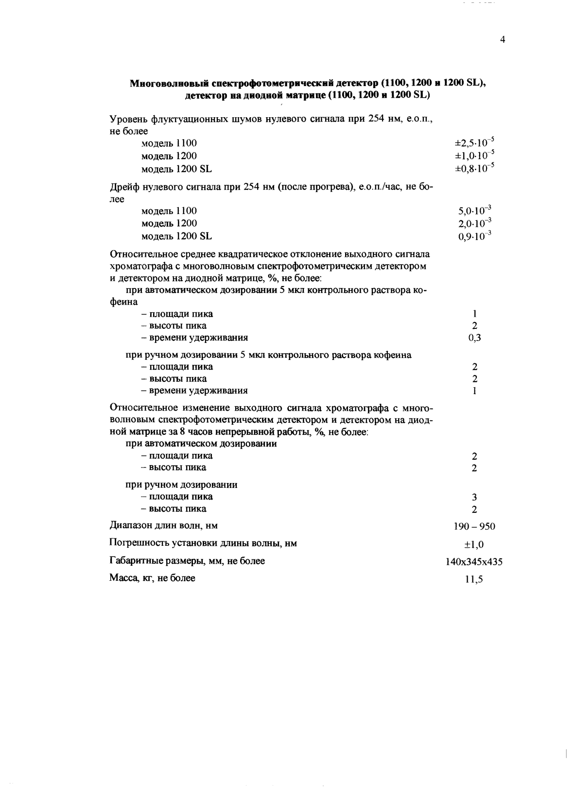
Многоволновый спектрофотометрнческий детектор (1100,1200 н 1200 SL), детектор на диодной матрице (1100,1200 и 1200 SL)
Уровень флуктуационных шумов нулевого сигнала при 254 нм, е.о.п., не более
модель 1100 ±2.5-10
модель 1200 ±1,0-10
модель 1200 SL ±0,8-10′
Дрейф нулевого сигнала при 254 нм (после прогрева), е.о.п./час, не более
модель 1100 5,0-10“3
модель 1200 2,0-10_3
модель 1200 SL 0,9-10 3
Относительное среднее квадратическое отклонение выходного сигнала хроматографа с многоволновым спектрофотометрическим детектором и детектором на диодной матрице, %, не более:
при автоматическом дозировании 5 мкл контрольного раствора кофеина
1
2
0,3
2
2
1
— площади пика
— высоты пика
— времени удерживания
при ручном дозировании 5 мкл контрольного раствора кофеина
— площади пика
— высоты пика
— времени удерживания
Относительное изменение выходного сигнала хроматографа с многоволновым спектрофотометрическим детектором и детектором на диодной матрице за 8 часов непрерывной работы, %, не более: при автоматическом дозировании
— площади пика 2
— высоты пика 2
при ручном дозировании
— площади пика 3
— высоты пика 2
Диапазон длин волн, нм 190 — 950
Погрешность установки длины волны, нм ±150
Г абаритные размеры, мм, не более 140x345x435
Масса, кг, не более 11 5
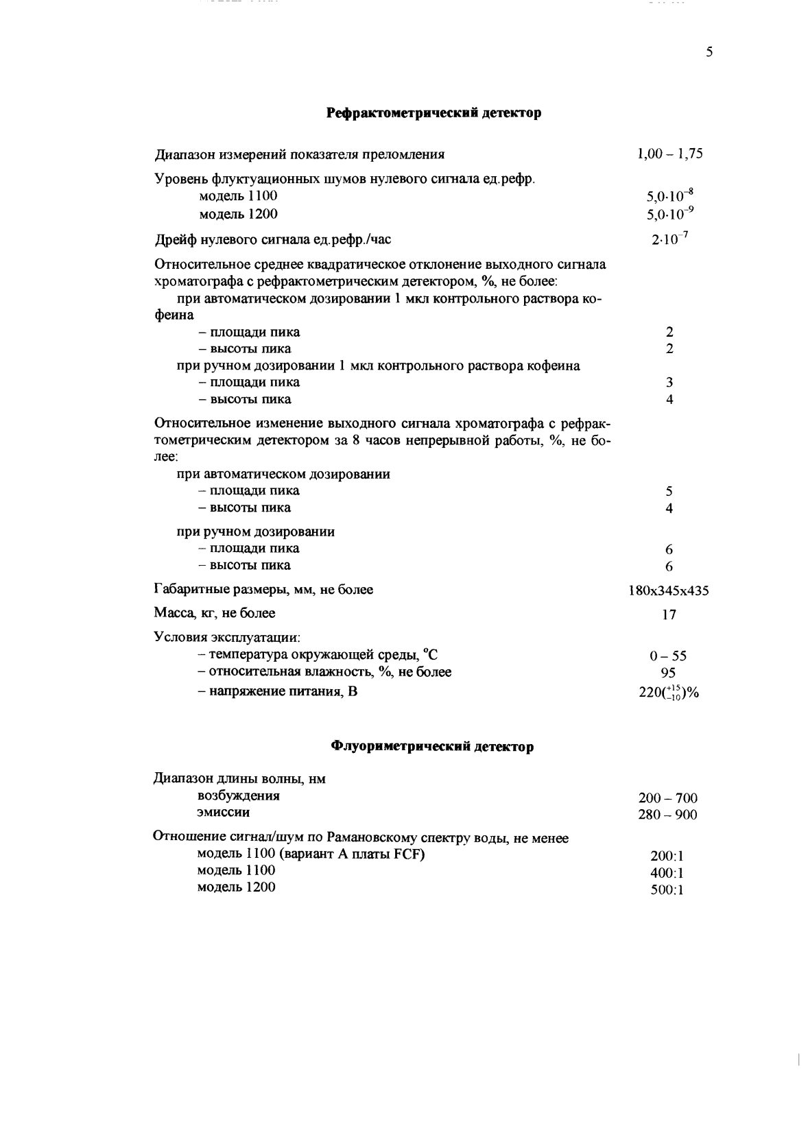
Диапазон измерений показателя преломления
Уровень флуктуационных шумов нулевого сигнала ед.рефр. модель 1100 модель 1200
1,00-1,75
5.0-10-8
5.0-10’9
2-10 7
2
2
3
4
5 4
6 6
180x345x435
17
0-55
95
2200%
200 — 700 280 — 900
200:1
400:1
500:1
Дрейф нулевого сигнала ед.рефр./час
Относительное среднее квадратическое отклонение выходного сигнала хроматографа с рефрактометрическим детектором, %, не более:
при автоматическом дозировании 1 мкл контрольного раствора кофеина
— площади пика
— высоты пика
при ручном дозировании 1 мкл контрольного раствора кофеина
— площади пика
— высоты пика
Относительное изменение выходного сигнала хроматографа с рефрактометрическим детектором за 8 часов непрерывной работы, %, не более:
при автоматическом дозировании
— площади пика
— высоты пика
при ручном дозировании
— площади пика
— высоты пика
Габаритные размеры, мм, не более Масса, кг, не более
Условия эксплуатации:
— температура окружающей среды, °С
— относительная влажность, %, не более
— напряжение питания, В
Флуориметрический детектор
Диапазон длины волны, нм возбуждения эмиссии
Отношение сигнал/шум по Рамановскому спектру воды, не менее модель 1100 (вариант А платы FCF) модель 1100 модель 1200
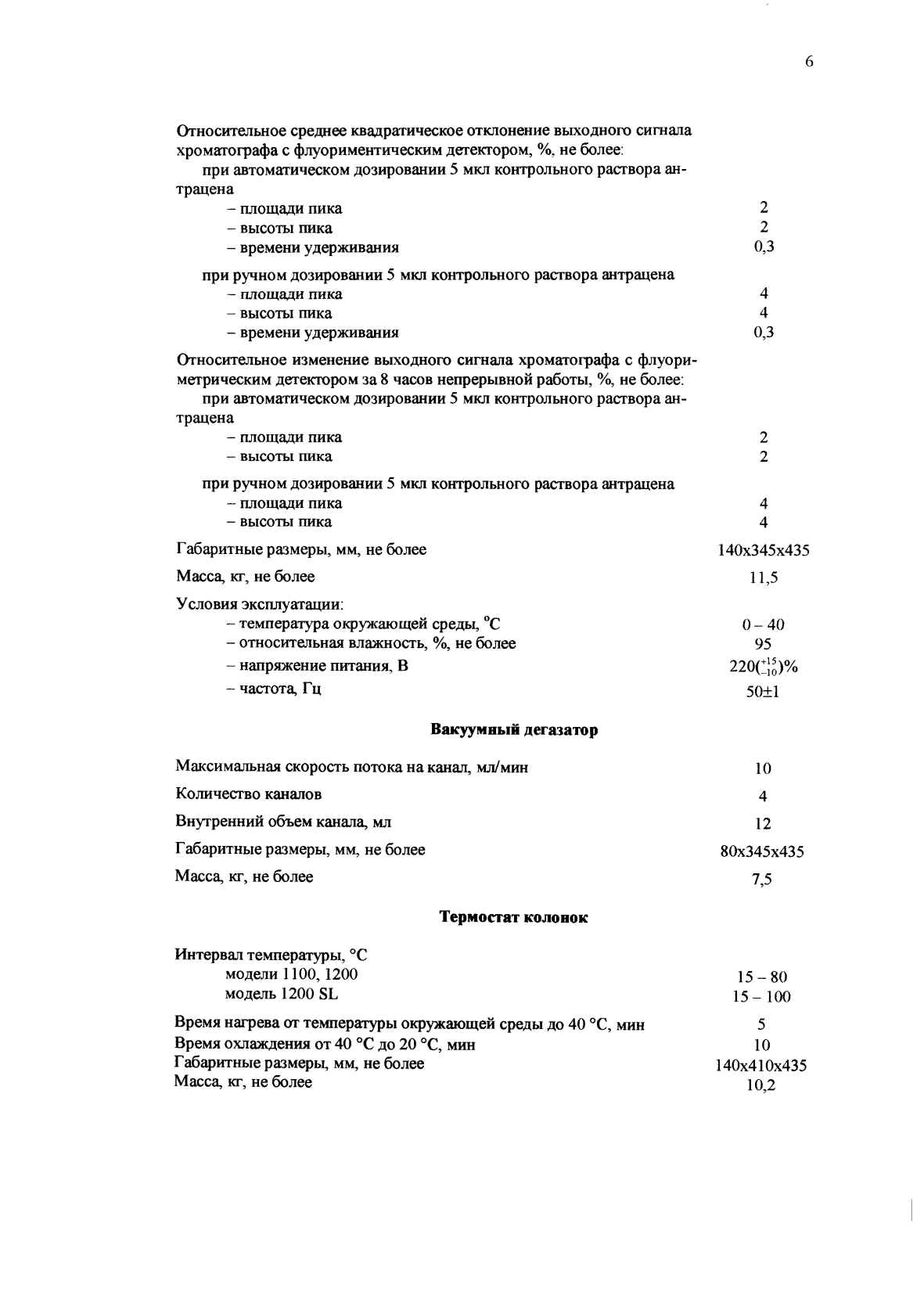
Относительное среднее квадратическое отклонение выходного сигнала хроматографа с флуориментическим детектором, %. не более:
при автоматическом дозировании 5 мкл контрольного раствора антрацена
— площади пика 2
— высоты пика 2
— времени удерживания 0,3
при ручном дозировании 5 мкл контрольного раствора антрацена
— площади пика 4
— высоты пика 4
— времени удерживания 0,3
Относительное изменение выходного сигнала хроматографа с флуори-метрическим детектором за 8 часов непрерывной работы, %, не более: при автоматическом дозировании 5 мкл контрольного раствора антрацена
— площади пика 2
— высоты пика 2
при ручном дозировании 5 мкл контрольного раствора антрацена
— площади пика 4
— высоты пика 4
Г абаритные размеры, мм, не более 140x345x435
Масса, кг, не более 11,5
Условия эксплуатации:
— температура окружающей среды, °С 0-40
— относительная влажность, %, не более 95
— напряжение питания, В 220(!}q)%
— частота, Гц 50+1
Вакуумный дегазатор
Максимальная скорость потока на канал, мл/мин 10
Количество каналов 4
Внутренний объем канала, мл 12
Г абаритные размеры, мм, не более 80x345x435
Масса, кг, не более 7,5
Термостат колонок
Интервал температуры, °С
модели 1100,1200 15-80
модель 1200 SL 15-100
Время нагрева от температуры окружающей среды до 40 °С, мин 5
Время охлаждения от 40 °С до 20 °С, мин 10
Г абаритные размеры, мм, не более 140x410x435
Масса, кг, не более 10,2
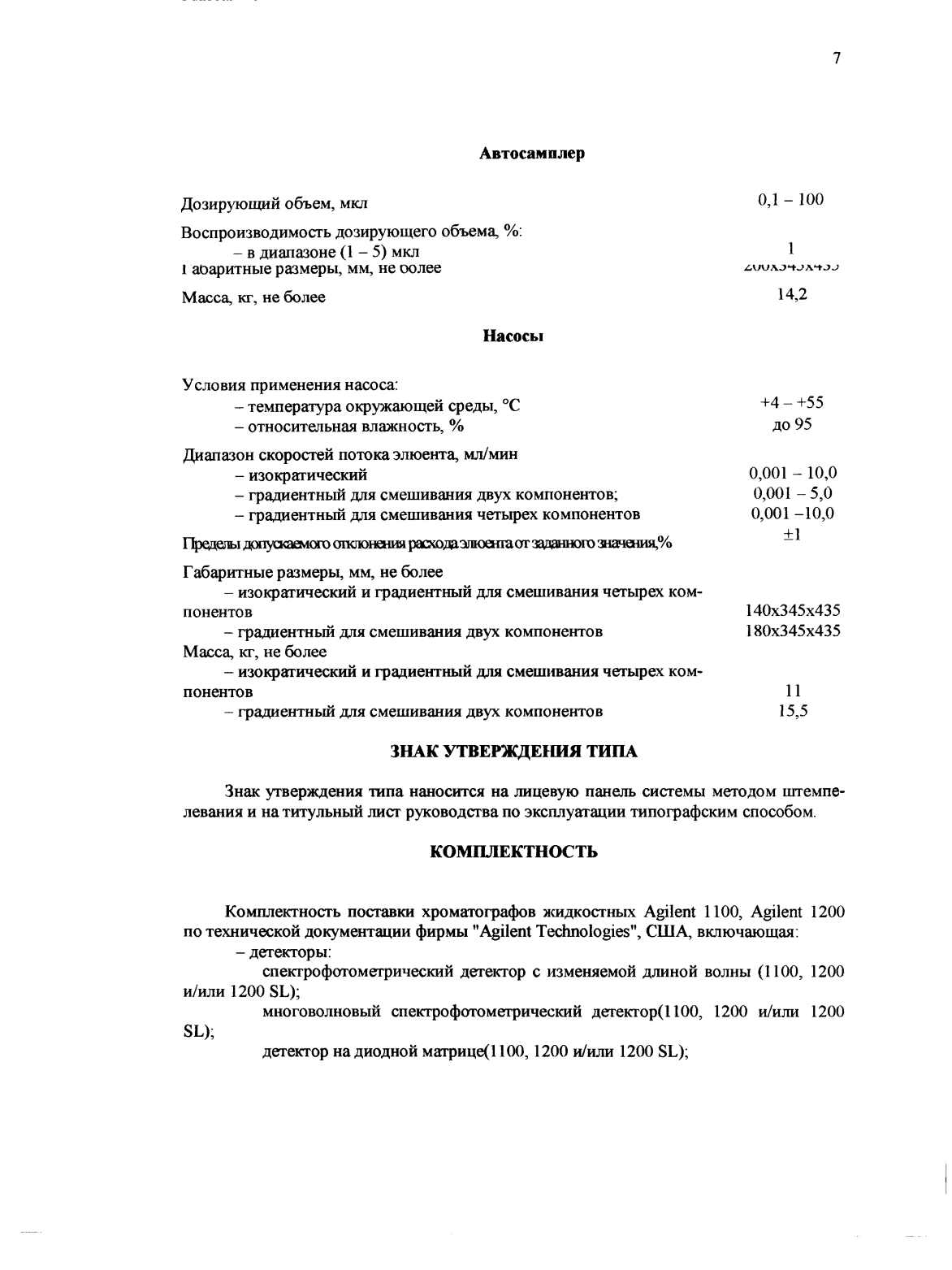
Автосамплер
Дозирующий объем, мкл
Воспроизводимость дозирующего объема, %:
— в диапазоне (1 — 5) мкл
14,2
1 аоаритные размеры, мм, не оолее
Масса, кг, не более
Насосы
Условия применения насоса:
+4 — +55 ДО 95
0,001 — 10,0 0,001 — 5,0 0,001 -10,0 +1
— температура окружающей среды, °С
— относительная влажность, %
Диапазон скоростей потока элюента, мл/мин
— изократический
— градиентный для смешивания двух компонентов;
— градиентный для смешивания четырех компонентов
Пределы допускаемого отклонения рагаодаэтоенгаог заданного знаяения,%
Г абаритные размеры, мм, не более
— изократический и градиентный для смешивания четырех компонентов
140x345x435
180x345x435
— градиентный для смешивания двух компонентов Масса, кг, не более
— изократический и градиентный для смешивания четырех компонентов
11
15,5
— градиентный для смешивания двух компонентов
Знак утверждения типа
Знак утверждения типа наносится на лицевую панель системы методом штемпв’ левания и на титульный лист руководства по эксплуатации типографским способом.
Комплектность
Комплектность поставки хроматографов жидкостных Agilent 1100, Agilent 1200 по технической документации фирмы «Agilent Technologies», США, включающая:
— детекторы:
спекгрофотомегрический детектор с изменяемой длиной волны (1100, 1200 и/или 1200 SL);
многоволновый спектрофотометрический детектор(1100, 1200 и/или 1200
SL);
детектор на диодной матрице(1100,1200 и/или 1200 SL);
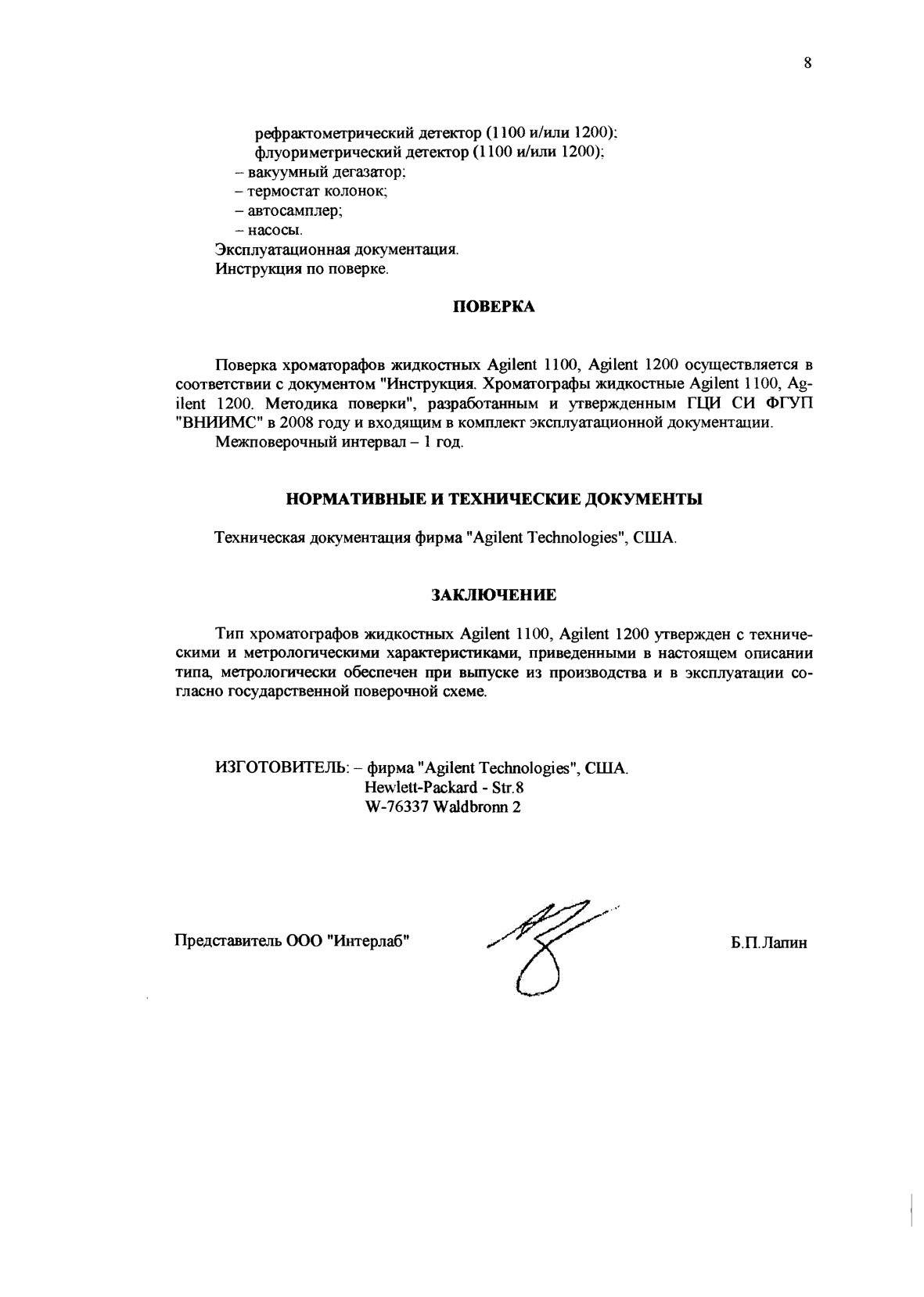
рефрактометрический детектор (1100 и/или 1200); флуориметрический детектор (1100 и/или 1200);
— вакуумный дегазатор;
— термостат колонок;
— автосамплер;
— насосы.
Эксплуатационная документация.
Инструкция по поверке.
Поверка
Поверка хроматорафов жидкостных Agilent 1100, Agilent 1200 осуществляется в соответствии с документом «Инструкция. Хроматографы жидкостные Agilent 1100, Agilent 1200. Методика поверки», разработанным и утвержденным ГЦИ СИ ФГУП «ВНИИМС» в 2008 году и входящим в комплект эксплуатационной документации. Межповерочный интервал — 1 год.
Нормативные документы
Техническая документация фирма «Agilent Technologies», США.
Заключение
Тип хроматографов жидкостных Agilent 1100, Agilent 1200 утвержден с техническими и метрологическими характеристиками, приведенными в настоящем описании типа, метрологически обеспечен при выпуске из производства и в эксплуатации согласно государственной поверочной схеме.
Хроматографы жидкостные Agilent 1100, Agilent 1200, ГРСИ 16193-06
Номер госреестра:
16193-06
Наименование СИ:
Хроматографы жидкостные
Обозначение типа:
Agilent 1100, Agilent 1200
Производитель:
Фирма «Agilent Technologies», США
Межповерочный интервал:
1 год
Сведения о типе СИ:
Срок свидетельства
Срок свидетельства:
01.07.2011
Поверка
Аккредитованная лаборатория
8(812)209-15-19, info@saprd.ru
К сожалению, комментарии пока что отсутствуют. Вы можете быть первым. Оставить комментарий:
Читать в отдельном окне
Untitled document
Готовы поверить данное средство измерений.
Поверка средств измерений.
| ГРСИ | Наименование СИ | Тип СИ | Производитель | МПИ | Ссылка |
| 23435-02 | Хроматографы жидкостные | Jasco | Фирма «Jasco», Япония | 1 год | Перейти |
| 12490-12 | Термометры технические жидкостные | ТТЖ-М | ПАО «Стеклоприбор», Украина, г.Червонозаводское | 3 года | Перейти |
| 21862-01 | Термометры жидкостные стеклянные | ASTM 8C-86 | Фирма «Miller & Weber», США | 2 года | Перейти |
| 18877-99 | Хроматографы жидкостные | Alliance | Фирма «Waters», США | 1 год | Перейти |
| 19419-00 | Хроматографы жидкостные | LC-10Avp | Фирма «Shimadzu», Япония | 1 год | Перейти |
Общество с ограниченной ответственностью
«Специализированное управление программ регионального развития»
ООО «СУПРР»
ИНН 7813337035 КПП 781301001 ОГРН 1057813279919
197198, Санкт-Петербург, ул. Шамшева, д. 8, лит. А, пом. 230
8(812)209-15-19
info@saprd.ru
![]()
Поверка средств измерений
ООО «СУПРР»
ИНН 7813337035 КПП 781301001
ОГРН 1057813279919
197198, Санкт-Петербург, ул. Шамшева, д. 8, лит. А, пом. 230
8(812)209-15-19
info@saprd.ru
![]()
Поверка средств измерений
-
Contents
-
Table of Contents
-
Troubleshooting
-
Bookmarks
Quick Links
Agilent 1100 Series
Capillary LC System
System Manual
s1
Related Manuals for Agilent Technologies 1100 Series
Summary of Contents for Agilent Technologies 1100 Series
-
Page 1
Agilent 1100 Series Capillary LC System System Manual… -
Page 2
CAUTION without prior agreement and written consequential damages in consent from Agilent Technologies, Inc. as notice until the indicated connection with the furnishing, use, governed by United States and conditions are fully understood international copyright laws. -
Page 3
1100 Series Capillary LC System apparatus against damage. Manual In This Manual… This manual contains information for using your Capillary LC System. Installing your Capillary LC System This chapter describes how to install and configure the Capillary LC System. -
Page 4
Here you find performance specifications of the Capillary LC systems Annex A Safety Information 1100 Series Capillary LC System Manual 1100 Series Capillary LC System Manual… -
Page 5: Table Of Contents
Install the Micro Vacuum Degasser (G1379A) Install the Solvent Cabinet Get the System Ready for the First Injection Manually Priming the Solvent Channels. Purging the Pump24 Conditioning the System Under Method Conditions Inject the Check-out Sample Procedure 1100 Series Capillary LC System Manual…
-
Page 6
How the Function Works 3 Capillaries and Fittings Capillary Flow Diagram Connecting capillaries for the capillary LC system Fittings and Ferrules Instructions to connect a capillary. Hints for Successful use of Capillaries and Fittings 1100 Series Capillary LC System Manual… -
Page 7
Capillary Pump Hydraulic Path Pump-Head Assembly Capillary pump cover parts Micro Well-plate Sampler Sampling Unit for the Micro Well-plate Sampler Micro Analytical Head Assembly Micro Injection Valve Assembly Micro Well-plate Sampler — Vial Trays 1100 Series Capillary LC System Manual… -
Page 8
Diode Array Detector Cover Parts Common Parts Control Module (G1323B) Rear panel Power and Status Light Pipes Leak Parts Foam parts Sheet metal kit Micro Degasser Accessory Kit Capillary Pump Preventive Maintenance Kit G1376-68710 viii 1100 Series Capillary LC System Manual… -
Page 9
Installing the 0.1 — 2.5 ml/min flow capillary kit Micro Column Switching Valve G1388A#055 Parts Identification for Micro Column Switching Valve Replacing Rotor Seal of Micro Column Switching Valve Removing the Micro Column Switching Valve Installing the Micro Column Switching Valve 1100 Series Capillary LC System Manual… -
Page 10
Connecting Small I.D. Capillaries Replacing or Cleaning Parts Performance Specifications Performance Specifications Agilent 1100 Series Capillary Pump Performance Specifications Agilent 1100 Series Micro Vacuum Degasser Performance Specifications Agilent 1100 Series Thermostatted Micro Autosampler Performance specification Agilent 1100 Series Micro Well-plate Sampler Performance Specifications Agilent 1100 Thermostatted Column Compartment. -
Page 11: Installing Your Capillary Lc System
Agilent 1100 Series Capillary LC System System Manual Installing your Capillary LC System Site Requirements Physical Specifications System Installation Process Installing a Capillary LC System with a Non-Thermostatted Sampler Installing a Capillary LC System with a Thermostatted Micro Sampler Get the System Ready for the First Injection…
-
Page 12: Site Requirements
Never operate your instrumentation from a power outlet that has no ground WARNING connection. Never use a power cord other than the power cord designed for your region. 1100 Series Capillary LC System Manual…
-
Page 13: Physical Specifications
Installing your Capillary LC System 1 Never use cables other than the ones supplied by Agilent Technologies to ensure proper functionality and compliance with safety or EMC regulations. Bench Space The modules dimensions and weight (see Table 2 on page 5) allow to place the Capillary LC system on almost any laboratory bench.
-
Page 14
< 95 %, at 25 – 40 °C (77 – 104 °F) Non-condensing Operating Altitude Up to 2000 m (6500 ft) Non-operating altitude Up to 4600 m (14950 ft) For storing the capillary pump Safety standards: IEC, CSA, UL Installation Category II, Pollution Degree 1100 Series Capillary LC System Manual… -
Page 15: System Installation Process
If the delivery packaging shows signs of external damage, please call your sales and service office immediately. Inform your service representative that something may have been damaged during shipment. CAUTION If there are signs of damage, please do not attempt to install the damaged module. 1100 Series Capillary LC System Manual…
-
Page 16: Installing A Capillary Lc System With A Non-Thermostatted Sampler
4 Connect one end of the LAN cross over cable (5183-4649) to the connector on the JetDirect card. Connect the other end of the LAN cross over cable to the Chemstation. 5 Connect the Can-bus cable (5181-1516) to one of the CAN connectors at the rear of the DAD. 1100 Series Capillary LC System Manual…
-
Page 17: Install The Thermostatted Column Compartment (Tcc) (G1316A)
7 Connect the DAD flow cell inlet capillary (G1315-68703) to the outlet of the NOTE Carefully route all capillaries so that they are not crushed analytical column. or broken by module front covers. Avoid excessive bending. Chapter 2 for advice on handling capillaries. 1100 Series Capillary LC System Manual…
-
Page 18
Installing your Capillary LC System NOTE If your TCC has a Micro Column Switching Valve, refer to the Micro Column Switching Valve information in Chapter 6 of this manual. 1100 Series Capillary LC System Manual… -
Page 19: Install The Micro Well-Plate Sampler (G1377A)
7 Connect one end of the sampler-to-column capillary (G1375-87304) to port 6 of the sampler injection valve. Connect the other end of this capillary to the inlet of the 1100 Series Capillary LC System Manual…
-
Page 20: Install The Capillary Pump (G1376A)
5 Connect the pre-terminated end of the pump-to-sampler capillary (G1375-87310) to the flow sensor outlet of the capillary pump. Connect the other end of this capillary to port 1 of the sampler injection valve. 1100 Series Capillary LC System Manual…
-
Page 21: Install The Micro Vacuum Degasser (G1379A)
4 The degasser accessory kit has a set of 4 solvent tubes (G1322-67300). Each tube is labeled A, B, C or D. Connect each solvent tube to its intended OUTLET channel port on the degasser. 1100 Series Capillary LC System Manual…
-
Page 22
5 Connect the other end of the solvent tube to its intended port at the pump solvent selection valve. Follow the guide below: Degasser Pump Solvent Selection OUTLET Valve Port A1 (left half, upper) A2 (left half, lower) B1 (right half, upper) B2 (right half, lower) 1100 Series Capillary LC System Manual… -
Page 23: Install The Solvent Cabinet
2 The solvent cabinet accessory kit has 4 bottle head assemblies (G1376-60003). 3 Connect a bottle head assembly to each of the degasser INLET ports. Use the labels provided with each bottle head assembly to appropriately label each bottle head assembly. 1100 Series Capillary LC System Manual…
-
Page 24: Installing A Capillary Lc System With A Thermostatted Micro Sampler
1 Place the thermostat for 1100 samplers (thermostat module) on the bench. The thermostat module should be no more than 25cm (9.8 inches) from the front edge of the bench. The thermostat module should be positioned as the bottom module in the right-hand stack. 1100 Series Capillary LC System Manual…
-
Page 25: Install The Micro Sampler (G1387A Micro Autosampler (Als), Or G1378A Micro Well-Plate Sampler)
Do not connect these power cables to power until you have finished the hardware installation of all modules in the stack. 7 Install the air channel adapter (G1329-43200) between the micro sampler and the thermostat module. See the sampler reference manual for more detail if required. 1100 Series Capillary LC System Manual…
-
Page 26: Install The Thermostatted Column Compartment (Tcc) (G1316A)
Can-bus connector at the rear of the TCC. 6 Place the analytical column into the TCC. Observe the flow direction indicated on the column. The column can later be secured using column clamp (5001-3702). 1100 Series Capillary LC System Manual…
-
Page 27: Install The Diode Array Detector (Dad) (G1315B)
9 Connect The DAD flow cell inlet capillary (G1315-68703) to the outlet of the analytical column. Ccarefully route all capillaries so that they are not crushed or broken by module front covers. Avoid excessive bending. See chapter 2 for advice on handling capillaries. 1100 Series Capillary LC System Manual…
-
Page 28: Install The Capillary Pump (G1376A)
EMPV. Route the waste tube to an appropriate waste container. 7 Connect the large-bore corrugated plastic leak drain tubing to the pump leak drain fitting. Route the leak drain tubing to an appropriate waste container. 1100 Series Capillary LC System Manual…
-
Page 29: Install The Micro Vacuum Degasser (G1379A)
Install the Solvent Cabinet 1 Place the solvent cabinet on top of the degasser. Make sure that the two modules are interlocked correctly. 2 The solvent cabinet accessory kit has 4 bottle head assemblies (G1376-60003). 1100 Series Capillary LC System Manual…
-
Page 30
Installing your Capillary LC System 3 Connect a bottle head assembly to each of the degasser INLET ports. Use the labels provided with each bottle head assembly to appropriately label each bottle head assembly. 1100 Series Capillary LC System Manual… -
Page 31: Get The System Ready For The First Injection
When opening capillary or tube fittings, solvents may leak. Please observe appropriate safety precautions (such as eye protection, safety gloves, protective clothing) as described in the material handling information and safety data sheet supplied by the solvent vendor, especially when hazardous solvents are used. 1100 Series Capillary LC System Manual…
-
Page 32: Manually Priming The Solvent Channels
Make sure that the pump leak sensor is dry before turning on the pump. Purging the Pump 1 Make sure that the 1/8 inch plastic waste tube is tightly connected to the barbed waste fitting of the pump EMPV, and routed to an appropriate waste container. 1100 Series Capillary LC System Manual…
-
Page 33
When the pump has been turned off for a certain time (for example, overnight), oxygen will re-diffuse into the channels between the degasser and the pump. It is suggested to purge each channel at 2500 µl/min for 1 minute at the beginning of each day. 1100 Series Capillary LC System Manual… -
Page 34: Conditioning The System Under Method Conditions
Best solvent to re-dissolve salts After the installation of Hexane + Good wetting properties normal phase seals ( P/N 5 % Isopropanol 0905-1420) To clean the capillaries Acetone Best solvent to remove impurities from the capillaries 1100 Series Capillary LC System Manual…
-
Page 35: Inject The Check-Out Sample
The purpose of the instrument check is to demonstrate that all modules of the instrument are correctly installed and connected. It is not a test of the instrument performance. A single injection of the Agilent Technologies isocratic test sample (Agilent part number 01080-68704) is made under the method conditions given below: Table 4…
-
Page 36: Procedure
1. The exact profile of the chromatogram will depend on the chromatographic conditions. Variations in solvent quality, column packing, standard concentration and column temperature will all have a potential effect on peak retention and response. 1100 Series Capillary LC System Manual…
-
Page 37
Installing your Capillary LC System 1 Figure 1 Typical chromatogram for check-out sample 1100 Series Capillary LC System Manual… -
Page 38
Installing your Capillary LC System 1100 Series Capillary LC System Manual… -
Page 39: Optimizing Performance
Agilent 1100 Series Capillary LC System System Manual Optimizing Performance Hints for Successful Use of the Capillary Pump Solvent Information Prevent Blocking of Solvent Inlet Filters Hints for the Micro Vacuum Degasser When to use Alternative Seals How to Choose the Primary Flow…
-
Page 40: Hints For Successful Use Of The Capillary Pump
• Make sure to observe the minimum recommended flow setpoint: • Normal mode100 µl/min • Micro mode, 20 µl flow sensor: 1 µl/min • Micro mode, 100 µl flow sensor:10 µl/min 1100 Series Capillary LC System Manual…
-
Page 41: Fused Silica Capillary Issues
• For fast gradient use valve to bypass function after the sample is transferred to the column. This function results in smaller delay times and sharper gradient curves. • When doing automated gradient runs, use the fast composition change/reconditioning function to equilibrate the system between runs. 1100 Series Capillary LC System Manual…
-
Page 42: Column Thermostat Issues
• Mixtures of carbon tetrachloride with 2-propanol or THF dissolve stainless steel. • Avoid the use of alkaline solutions (pH > 8.5) which can attack the fused silica from the capillaries. Prevent Blocking of Solvent Inlet Filters 1100 Series Capillary LC System Manual…
-
Page 43: Cleaning The Solvent Filters
Cleaning the Solvent Filters • Remove the blocked solvent filter from the bottle-head assembly and place it in a beaker with concentrated nitric acid (65%) for one hour. 1100 Series Capillary LC System Manual…
-
Page 44
• Thoroughly flush the filter with bidistilled water (remove all nitric acid, some columns can be damaged by nitric acid). • Replace the filter. Never use the system without solvent filters. This could cause damage to the pump CAUTION valves 1100 Series Capillary LC System Manual… -
Page 45: Hints For The Micro Vacuum Degasser
• capillary pump was turned OFF for a length of time (for example during night) and volatile solvent mixtures are used. For more information see the Reference Manual for the Agilent 1100 series micro vacuum degasser. When to use Alternative Seals The standard seals for the capillary pump can be used for most applications.
-
Page 46: How To Choose The Primary Flow
(<3 min.). Solvent consumption is highest in this range. Table 5 gives approximate primary flow values (in µl/min) as a function of selected primary flow range vs. system pressure: 1100 Series Capillary LC System Manual…
-
Page 47: Static Mixer And Filter
• The delay volume of the capillary pump should be reduced to a minimum for fastest gradient response. • The detector is used at medium or low sensitivity. NOTE Removing the mixer will result in an increase of the composition wander and higher detector noise. 1100 Series Capillary LC System Manual…
-
Page 48: How To Optimize The Compressibility Compensation Setting
1100 control module, the pressure and%-ripple can be monitored with one of these instruments, otherwise connect a signal cable between the pressure output of the capillary pump and a recording device (for example, 339X integrator) and set parameters. Zero 50 % 1100 Series Capillary LC System Manual…
-
Page 49
Optimize your compressibility settings by using the values for various solvents listed in the following table: Table 6 Solvent Compressibility Solvent (pure) Compressibility (10 /bar) Acetone Acetonitrile Benzene Carbon tetrachloride Chloroform Cyclohexane Ethanol Ethyl acetate Heptane Hexane Isobutanol Isopropanol Methanol 1-Propanol 1100 Series Capillary LC System Manual… -
Page 50: The Fast Composition Change/Reconditioning Function
The pump delivers a high flow rate at the initial composition defined in the current method. This flow is maintained for the Fast System Flush time defined in the user interface. During this time, the system is being re-equilibrated, up to the sampler needle outlet. 1100 Series Capillary LC System Manual…
-
Page 51
The column is reconditioned for the Column Reconditioning time defined in the user interface. If multiple injections are in progress, the next injection will begin when Fast Composition Change/Reconditioning is completed. 1100 Series Capillary LC System Manual… -
Page 52: Capillaries And Fittings
Agilent 1100 Series Capillary LC System System Manual Capillaries and Fittings Capillary Flow Diagram Connecting capillaries for the capillary LC system Fittings and Ferrules Instructions to connect a capillary. Hints for Successful use of Capillaries and Fittings…
-
Page 53: Capillary Flow Diagram
Figure 2 Capillary flow diagram of the Agilent 1100 system capillary LC system Connecting capillaries for the capillary LC system Table 7 Generic capillaries for use with a capillary LC system 1100 Series Capillary LC System Manual…
-
Page 54
Refer to Table Table 9 on page 48, Table Table 11 on page 50, or Table 12 page 50 for specific capillaries. Table 8 Specific capillaries for use with a 20 µl flow sensor 1100 Series Capillary LC System Manual… -
Page 55
NOTE The pressure drops in Table 9 are calculated for water (viscosity 1) and for a flow rate of 50 µl/min. Table 10 Specific capillaries for use with a flow higher than 200 µl/min 1100 Series Capillary LC System Manual… -
Page 56
The pressure drops in Table 10 are calculated for water (viscosity 1) and for a flow rate NOTE 1000 µl/min. Table 11 Specific capillaries for use with a micro CSV and a 20 µl flow sensor 1100 Series Capillary LC System Manual… -
Page 57
Column 1 inlet G1375-87309 Column 1 outlet Micro CSV (Port 6) G1375-87309 Micro CSV (Port 1) Detector G1375-87309 Micro CSV (Port 3) Column 2 inlet G1375-87309 Column 2 outlet Micro CSV (Port 2) G1375-87309 1100 Series Capillary LC System Manual… -
Page 58
(viscosity = 1). For other solvents or other flow rates, use the indicated relation to calculate the approximate pressure drop. Depending on tolerance of the capillary diameter the pressure drop values can vary by +/- 25% compared to the calculated results. 1100 Series Capillary LC System Manual… -
Page 59
Capillaries and Fittings Pressure (Bar) = s) x Length(mm) x 21333 / 3.14 x Diameter4 (µm) Flow(µl/min) x Viscosity (mPa 1100 Series Capillary LC System Manual… -
Page 60: Fittings And Ferrules
Capillaries and Fittings Fittings and Ferrules Table 14 Fittings and ferrules Fitting Name Description Conditioning Part Number Type Swagelock 1/16” SST fitting, front and back 10/pk 5062-2418 ferrule Lite Touch M4/16” SST fitting 10/pk 5063-6593 Lite Touch 1/32” SST ferrule and lock ring 10/pk 5065-4423 Rheodyne…
-
Page 61: Instructions To Connect A Capillary
Capillaries and Fittings 1100 Series Capillary LC System Manual Instructions to connect a capillary. With Swagelock fitting (type A) • Slide the nut, the compression ring and the ferrule onto the tubing. • Insert into the receiving port and finger tighten the fitting into the port.
-
Page 62: Hints For Successful Use Of Capillaries And Fittings
• A blocked capillary can often be cleaned by flushing it back. Acetone is recommended for this. • Take care when applying module doors, not to crush capillaries. • A broken capillary can release silica particles in the system. 1100 Series Capillary LC System Manual…
-
Page 63
Agilent 1100 Series Capillary LC System System Manual Basic System Troubleshooting System Pressure Abnormally Low System Pressure Abnormally High EMPV failed to initialize (micro mode only) Unstable column flow and/or system pressure Poor peak shape Failure to produce peaks, or abnormally small peaks, after injection… -
Page 64: Basic System Troubleshooting
System Pressure Abnormally High Symptoms: The current system pressure is significantly above the typical system pressure produced by this method with this column. System Pressure Abnormally High: Possible causes and actions Possible Causes Suggested Actions Notes 1100 Series Capillary LC System Manual…
-
Page 65: Empv Failed To Initialize (Micro Mode Only)
An attempt to pump in the micro mode has resulted in either an EMPV Initialization Failed error message, or a permanent EMPV Initialization not ready message. EMPV failed to initialize: Possible Causes and Suggested Actions 1100 Series Capillary LC System Manual…
-
Page 66: Unstable Column Flow And/Or System Pressure
Therefore, in the micro mode, unstable column flow and unstable system pressure usually appear together. Unstable column flow and/or system pressure: Possible Causes and Suggested Actions 1100 Series Capillary LC System Manual…
-
Page 67
EMPV performance test. Refer to the Capillary Pump Reference Manual. Any system component • Replace the analytical column. which is offering a changing • Replace the filter frit in front (upstream) of restriction to the pump. EMPV. 1100 Series Capillary LC System Manual… -
Page 68: Poor Peak Shape
Make sure the capillary connections are correctly made throughout the system, especially in the following areas: All micro-sampler valve ports. Column inlet and outlet. Flow cell inlet capillary, at the capillary/cell body junction. 1100 Series Capillary LC System Manual…
-
Page 69: Failure To Produce Peaks, Or Abnormally Small Peaks, After Injection
Any For best results in clearing bubbles which have formed in the chamber bubbles, the mobile phase being will now be cleared by the flow. pumped should not contain water. 1100 Series Capillary LC System Manual…
-
Page 70: Wandering Detector Baseline
For an phase. isocratic analysis, premixing and pumping The detector reacts to gluts of the 100% one channel is the best solution. more detectable parts of the 1100 Series Capillary LC System Manual…
-
Page 71: User Interface Displays Error Messages For Specific Modules
A specific error message for that specific hardware failure the module. Follow the advice on module is displayed. during operation troubleshooting and repair for the error message The status indicator of that module displayed. is red. 1100 Series Capillary LC System Manual…
-
Page 72: Parts And Materials
Agilent 1100 Series Capillary LC System System Manual Parts and Materials Micro Vacuum Degasser 66, Capillary Pump Micro Well-plate Sampler Thermostatted Micro Autosampler Thermostatted Column Compartment Diode Array Detector 101, Common Parts Cables This chapter shows detailed illustrations and lists for the parts identification for the complete system.
-
Page 73: Micro Vacuum Degasser
Parts and Materials Agilent Technologies Micro Vacuum Degasser Table 16 gives an overview over the main assemblies: Table 16 Micro vacuum degasser main assemblies Item Description Part Number Vacuum degasser control assembly G1322-66500 Board clip G1322-43100 Solenoid valve G1322-60003 Vacuum tube set…
-
Page 74
Parts and Materials Figure 4 Micro vacuum degasser main assemblies 1100 Series Capillary LC System Manual 1100 Series Capillary LC System Manual… -
Page 75: Micro Vacuum Degasser Cover Parts
Parts and Materials Micro Vacuum Degasser Cover Parts Table 17 Micro vacuum degasser cover parts Item Description Part Number Cabinet kit, includes base, side panels, top and front cover 5062-8579 Tube clip 5041-8387 Logo plate, Agilent 1100 5042-1381 Front cover 5062-8580 Figure 5 Micro vacuum degasser cover parts Capillary Pump…
-
Page 76
EMPV holding screw (pack of 2) 0515-0850 EMPV valve body G1361-60009 EMPV complete assembly (valve and solenoid) G1361-60000 AIV connecting cable G1311-61601 Damping unit 79835-60005 Fan assembly 3160-1017 1100 Series Capillary LC System Manual 1100 Series Capillary LC System Manual… -
Page 77: Solvent Cabinet And Bottle Head Assembly
Parts and Materials Figure 6 Capillary pump main assembly Solvent Cabinet and Bottle Head Assembly Table 19 Solvent cabinet and bottle-head assembly Item Description Part Number Solvent cabinet, complete assembly 5062-8581 Solvent tubing 5 m 5062-2483 Tube screw (pack of 10) 5063-6599 Ferrules with lock ring (pack of 10) 5063-6598…
-
Page 78: Capillary Pump Hydraulic Path
Bottle-head assembly for Capillary pump G1311- 60003 includes items 1, 2, 3, 5 Figure 7 Solvent cabinet and bottle head assembly 1100 Series Capillary LC System Manual Capillary Pump Hydraulic Path Table 20 Capillary pump hydraulic path Item Description Part Number…
-
Page 79
Parts and Materials FS to inj valve cap (550 mm, 50 µm) for 20 µl flow sensor G1375-87310 FS to inj valve cap (550 mm, 100 µm) for 100 µl flow sensor G1375-87306 Restriction capillary G1312-67304 Connection tube G1311-67304 Mixing capillary G1312-67302 Filter assembly (includes frit) 5064-8273… -
Page 80: Pump-Head Assembly
Parts and Materials Pump-Head Assembly Table 21 Pump-head assembly Item Description Part Number Pump head assembly, includes items marked with (*) G1311-60004 Outlet ball valve G1312-60012 Screw lock 5042-1303 Screw M5, 60 mm 0515-2118 Apdater G1312-23201 1100 Series Capillary LC System Manual…
-
Page 81
5062-8562 Seal (pack of 2) or 5063-6589 Seal (pack of 2), for normal phase applications 0905-1420 Plunger housing (including springs) G1311-60002 Sapphire plunger 5063-6586 Support ring 5001-3739 Outlet valve to piston 2 capillary G1312-67300 1100 Series Capillary LC System Manual… -
Page 82: Capillary Pump Cover Parts
Capillary pump cover parts Item Description Part Number Plastic cover kit (includes top, base and both sides) G1312-68703 Front plate G1312-60011 Logo plate, Agilent 1100 5042-1381 Figure 10 Capillary pump cover parts Micro Well-plate Sampler 1100 Series Capillary LC System Manual…
-
Page 83
Sample Transport assembly for G1377A G1377-60009 Sampling Unit assembly for G1377/78A G1377-60008 (The assembly comes without injection valve and analytical head) SLS board (not shown) G1367-66505 Analytical Head assembly (40 µl) for G1377/78A G1377-60013 1100 Series Capillary LC System Manual… -
Page 84
G1367-60006 Ribbon Cable (from SLS to MTP) (not visible) G1367-81600 Sampler-TCC cap. (500 mm, 0.05 mm id) for G1377/78A G1375-87304 Fan (not visible) 3160-1017 Fan exhaust (not visible) 3160-4097 BCD board (not visible) G1351-68701 1100 Series Capillary LC System Manual… -
Page 85: Sampling Unit For The Micro Well-Plate Sampler
Parts and Materials Sampling Unit for the Micro Well-plate Sampler Figure 12 Sampling unit for the micro well-plate sampler Table 24 Sampling unit for the micro well-plate sampler Item Description Part Number 1100 Series Capillary LC System Manual…
-
Page 86
Seat capillary (150 mm 0.10 mm ID) for G1377-87101 Needle Seat G1375-87317 Seat capillary (150 mm 0.05 mm ID) for G1377-87101 Needle Seat G1375-87300 Flex board G1313-68715 Air barrier (not visible) G1367-44105 Stepper motor peristaltic pump (not visible) 5065-4409 1100 Series Capillary LC System Manual… -
Page 87: Micro Analytical Head Assembly
Micro Plunger assembly 5064-8293 Adapter 01078-23202 Micro seal support assembly G1377-60002 Metering seal (pack of 1) 5022-2175 G1377-27700 Head body Screw M5, 60 mm lg, for mounting of assembly 0515-2118 Figure 13 Micro analytical head assembly 1100 Series Capillary LC System Manual…
-
Page 88: Micro Injection Valve Assembly
Micro Inj.-valve assembly, incl. items 1 – 2 – 3 – 5 – 6 0101-1050 Isolation seal 0100-1852 Micro rotor seal (Vespel) 0100-2088 Micro Stator head 0100-2089 Stator screws 1535-4857 NOTE The micro injection valve assembly has no ceramic stator face. Note: 1100 Series Capillary LC System Manual…
-
Page 89: Micro Well-Plate Sampler — Vial Trays
Parts and Materials Micro Well-plate Sampler — Vial Trays Table 27 Micro well-plate sampler vial trays and tray base Item Description Part Number Tray for 2 plates + 10 × 2-ml vials G1367-60001 1100 Series Capillary LC System Manual…
-
Page 90
96 CappedAgilent 47.1 5065-4402 96 Corning 14.3 No Agilent PN 96 CorningV 14.3 No Agilent PN 96 DeepAgilent31mm 31.5 1000 5042-6454 96 DeepNunc31mm 31.5 1000 No Agilent PN 96 DeepRitter41mm 41.2 No Agilent PN 1100 Series Capillary LC System Manual… -
Page 91: Micro Well-Plate Sampler Cover Parts
Item Description Part Number Cabinet kit, includes base, side panels, top and front cover 5065-4446 Name plate for Agilent 1100 Series 5042-1381 Light protection kit, includes dark front cover and side window 5064-8272 Figure 16 Micro well-plate sampler cover parts…
-
Page 92
Sampler -TCC cap (500 mm 50 µm) with a 20 µl FS G1375-87304 Sampler -TCC cap (500 mm 75 µm) with a 100 µl FS G1375-87311 BCD board (not shown) G1351-68701 Cable, autosampler to ALS thermostat G1330-81600 1100 Series Capillary LC System Manual… -
Page 93: Thermostat For 1100 Samplers
Parts and Materials Figure 17 Thermostatted micro autosampler main assemblies Thermostat for 1100 Samplers Table 31 Thermostat for micro autosampler and micro well-plate sampler Description Part Number Thermostat for 1100 samplers, exchange assembly G1330-69020 1100 Series Capillary LC System Manual…
-
Page 94: Sampling Unit For The Micro Autosampler
Parts and Materials Figure 18 Thermostat Sampling Unit for the Micro Autosampler Figure 19 offers an overview over the main assemblies of the Thermostatted Micro Autosampler. For descriptions of the item numbers refer to Table 1100 Series Capillary LC System Manual…
-
Page 95
G1329-60018 (The assembly comes without injection valve and analytical head) Sampling unit connector board (SUD) G1313-66503 Belt gear for metering unit and needle arm 1500-0697 Stepper motor for metering unit and needle arm 5062-8590 1100 Series Capillary LC System Manual… -
Page 96: Micro Analytical Head Assembly
Clamp Kit (includes needle clamp and 2 x clamp screw) G1313-68713 Micro Analytical Head Assembly Table 33 Micro analytical head assembly Item Description Part Number Micro Analytical head assembly 40 µl, includes items 1 – 6 G1377-60013 Screws 0515-0850 Micro Plunger assembly 5064-8293 1100 Series Capillary LC System Manual…
-
Page 97: Micro Injection Valve Assembly
Item Description Part Number Micro Inj.-valve assembly, incl. items 1 – 2 – 3 – 5 – 6 0101-1050 Isolation seal 0100-1852 Micro rotor seal (Vespel) 0100-2088 Micro Stator head 0100-2089 Stator screws 1535-4857 1100 Series Capillary LC System Manual…
-
Page 98
Parts and Materials NOTE The micro injection valve assembly has no ceramic stator face 1100 Series Capillary LC System Manual… -
Page 99: Thermostatted Micro Autosampler Cover Parts
Item Description Part Number Autosampler Cover kit G1329-68703 ( include base, side panels and top cover ) Name plate for Agilent 1100 Series 5042-1381 Transparent front cover G1313-68704 Door repair kit (includes transparent side and front door) G1329-68707 Light protection kit (includes opaque side and front door,…
-
Page 100: Vial Trays
Parts and Materials 1100 Series Capillary LC System Manual Vial Trays Table 36 Thermostatted autosampler vial trays and tray base Item Description Part Number Tray for 100 × 2-ml vials, thermostattable G1329-60001 Adapter, air channel G1329-43200 Tray base (includes items 4, 5, 6).
-
Page 101
G1316-60007 Leak handling parts page 100 Column switching valve, additional column switching valve parts, 0101-1051 page 97 Cable CAN to Agilent 1100 Series modules 5181-1516 Column identification board CID G1316-66503 Low dispersion capillary (0.12 mm i.d., 70 mm) G1316-87303 Capillary Kit Column Switching, see… -
Page 102: Micro Column Switching Valve
Micro Column Switching Valve Table 38 Micro column switching valve Item Description Part Number Column switching valve (complete assembly) 0101-1051 Rotor seal 3 grooves (Vespel) 0100-2087 Stator ring No PN Stator Head 0100-2089 Stator screw 1535-4857 1100 Series Capillary LC System Manual…
-
Page 103: Thermostatted Column Compartment Sheet Metal Kit
Thermostatted Column Compartment Sheet Metal Kit Table 39 Thermostatted column compartment sheet metal kit Item Description Part Number Sheet metal kit includes items 1, 2 and 3 G1316-68701 RFI shield G1316-00600 RFI spring side G1316-09100 RFI spring bottom G1316-09102 1100 Series Capillary LC System Manual…
-
Page 104: Thermostatted Column Compartment Cover Parts
Thermostatted column compartment sheet metal kit Thermostatted Column Compartment Cover Parts Table 40 Thermostatted column compartment cover parts Item Description Part Number Plastic kit, includes base, sides and top G1316-68703 Front cover G1316-68704 Name plate Agilent 1100 Series 5042-1381 1100 Series Capillary LC System Manual…
-
Page 105: Thermostatted Column Compartment Leak Parts
Waste assembly, includes complete Y-tubing assembly with G1316-60002 leak funnel Leak Kit, includes leak top and leak base G1316-68700 O-ring for ambient temperature sensor 0400-0002 Corrugated waste tube, 120 cm (re-order 5 m) 5062-2463 1100 Series Capillary LC System Manual…
-
Page 106: Diode Array Detector
G1351-68701 Main board DAM for G1315B DAD (exchange assembly) G1315-69530 Power supply 0950-2528 Leak sensor assembly 5061-3356 500 nl flow cell kit G1315-68714 Tungsten lamp G1103-60001 Longlife Deuterium lamp 5181-1530 Standard Deuterium lamp 2140-0590 1100 Series Capillary LC System Manual…
-
Page 107: Dad — Optical Unit Assembly
G1315-69002 parts, see page 81 Fuse for BCD board, 250 mA (total of 4 are on the board) 2110-0004 Cable CAN to Agilent 1100 Series modules 5181-1516 Figure 29 Diode array detector main assemblies DAD — Optical Unit Assembly Table 43 gives an overview over optical unit parts:.
-
Page 108
9, 10, 11 Holmium oxide filter parts, see page 108 Spring, for other holmium oxide filter parts, see page 108 1460-1510 Coupling lens assembly G1103-68001 Source lens (achromate) assembly G1315-65201 Cell support assembly G1315-65202 Sealing G1315-47103 1100 Series Capillary LC System Manual… -
Page 109
Parts and Materials 1100 Series Capillary LC System Manual… -
Page 110: 500 Nl Flow Cell
PEEK fitting 1/32, not attached to capillaries 5063-6592 Upchurch Litetouch ferrules LT-100, (front and back), QTY=4 5063-6592 ( reorder 10/pk ) Union — Top — Adjustment Tool, used for item #7 5022-2146 Union — Top — Seal, QTY=2 5022-2145 1100 Series Capillary LC System Manual…
-
Page 111: Fan Assembly Parts
G1315-68715 Wrench open end 4 mm 8710-1534 † part of Sealing Kit † supplied with standard accessory kit G1315-68705 Fan Assembly Parts Table 45 Fan assembly parts Item Description Part Number Heater assembly G1315-60000 1100 Series Capillary LC System Manual…
-
Page 112: Holmium Oxide Filter
Holmium oxide filter motor assembly, includes items 2 and 4 G1315-68700 NOTE When the filter motor has been removed, the filter lever should not be reused. Use always a new filter lever to assure correct fit on the filter motor shaft. 1100 Series Capillary LC System Manual…
-
Page 113: Diode Array Detector Cover Parts
Table 47 Diode array detector cover parts Item Description Part Number Name plate Serial Number (w/o serial number) 5042-1314 Plastics, includes base, sides and top 5062-8565 Name plate Agilent 1100 Series 5042-1381 Front cover 5062-8582 1100 Series Capillary LC System Manual…
-
Page 114: Common Parts
Table 48 Control Module Parts Description Part Number Control Module, replacement part including cable G1323-67001 Plastic Housing Kit, includes front, back and a clamp 5062-8583 CAN cable Agilent 1100 module to control module G1323-81600 1100 Series Capillary LC System Manual…
-
Page 115: Rear Panel
Nut M14 — analog output 2940-0256 Screw, M4, 7 mm lg — power supply 0515-0910 Standoff — GPIB connector 0380-0643 Figure 36 Rear panel Power and Status Light Pipes Table 50 Power and status light pipes 1100 Series Capillary LC System Manual…
-
Page 116: Leak Parts
Holder, leak funnel 5041-8389 Leak funnel 5041-8388 Tube clip 5041-8387 Leak plane, pump 5041-8390 Leak plane, degasser G1379-47300 Leak plane, ALS, WPS G1313-44501 Leak plane, TCC, for details see page 100 G1316-68700 Leak plane, DAD G1315-45501 1100 Series Capillary LC System Manual…
-
Page 117: Foam Parts
Interface board guides 5041-8395 ( board guides for the G1376A/ G1389A/ G1377A/ G1315B ) Bushing for pump drive 1520-0404 Damper kit (includes 7 bumpers) for DAD G1315-68706 Sheet metal kit Table 53 Sheet metal kit 1100 Series Capillary LC System Manual…
-
Page 118: Micro Degasser Accessory Kit
Table 54 G1329A — Micro degasser accessory kit contents G1322-68705 Description Part Number Fitting tool 0100-1710 Solvent tubing kit (4 tubes degasser to pump) G1322-67300 Syringe 5062-8534 Syringe adapter 9301-1337 † Waste tube 5062-2463 Reorder number (pack of 10) † Reorder number (5m) 1100 Series Capillary LC System Manual…
-
Page 119: Capillary Pump Preventive Maintenance Kit G1376-68710
Wrench open end 14 mm (x 1) 8710-1924 Wrench open end 4 mm, (x 1) 8710-1534 Hex key 2.5 mm, 15 cm long, straight handle (x 1) 8710-2412 Hex key 3.0 mm, 12 cm long (x 1) 8710-2411 1100 Series Capillary LC System Manual…
-
Page 120: Micro Well-Plate Sampler Accessory Kit G1377-68705
5181-1519 Vials, screw cap 100/pk 5182-0716 Blue screw caps 100/pk 5182-0717 Valve catalog 5988-2999 Hex key 9/64 inch (for injection-valve screws) 8710-0060 Wrenches 1/4 – 5/16 inch 8710-0510 Wrench 4.0 mm open end 8710-1534 1100 Series Capillary LC System Manual…
-
Page 121: Thermostatted Micro Autosampler Accessory Kit
CAN cable, 1 m long 5181-1519 Screw cap vials, clear 100/pk 5182-0714 Blue screw caps 100/pk 5182-0717 Label halftray no PN Fitting 5061-3303 Hex Key 8710-0060 Wrench 4 mm both ends 8710-1534 Wrenches 1/4 — 5/16 inch 8710-0510 1100 Series Capillary LC System Manual…
-
Page 122: Column Compartment With Micro Column Selection Valve Accessory Kit
Column identification tag (x1) reorder number (3 / pack) 5062-8588 Corrugated waste tube reorder number (5 m) 5062-2463 CAN cable 5181-1516 Wrenches 1/4 — 5/16 inch 8710-0510 ESD wrist strap no PN Column clip (x4) reorder number (6 / pack) 5063-6526 1100 Series Capillary LC System Manual…
-
Page 123: Dad Accessory Kit
Ferrule back SST, qty=10 5180-4114 Fitting SST, qty=10 5061-3303 Hex key set 1 – 5 mm 8710-0641 Wrench open end 1/4 – 5/16 inch 8710-0510 Wrench open end 4 mm 8710-1534 ESD wrist strap no PN 1100 Series Capillary LC System Manual…
-
Page 124: Cables
Parts and Materials Cables Never use cables other than the ones supplied by Agilent Technologies to ensure WARNING proper functionality and compliance with safety or EMC regulations. Table 61 offers an overview over all cables supplied: Table 61 Cables overview…
-
Page 125
Agilent 1100 module to module, 1 m 5181-1519 Agilent 1100 module to control module G1323-81600 External contacts Agilent 1100 Series interface board to general purpose G1103-61611 GPIB cable Agilent 1100 module to Agilent ChemStation, 1 m 10833 A Agilent 1100 module to Agilent ChemStation, 2 m… -
Page 126
Parts and Materials Twisted pair cross over LAN cable, 10 feet long LAN cable 5183-4649 ( for point to point connection ) Category 5 UTP cable, 8 m long G1530-61480 ( for hub connections ) 1100 Series Capillary LC System Manual… -
Page 127: Analog Cables
Parts and Materials Analog Cables One end of these cables provides a BNC connector to be connected to Agilent 1100 Series modules. The other end depends on the instrument to which connection is being made. Table 62 Agilent 1100 to 3390/2/3 integrators Connector Signal Name 01040-60101…
-
Page 128: Remote Cables
Remote Cables One end of these cables provides a Agilent Technologies APG (Analytical Products Group) remote connector to be connected to Agilent 1100 Series modules. The other end depends on the instrument to be connected to. Table 66 Agilent 1100 to 3390 integrators…
-
Page 129
Parts and Materials Connector Signal Name Active 01046-60203 3390 Agilent 1100 ( TTL ) 1 — White Digital ground 2 — Brown Prepare run 3 — Gray Start 4 — Blue Shut down 5 — Pink Not connected 6 — Yellow Power on High 7 — Red… -
Page 130
High 7 — Red Ready High 8 — Green Stop 9 — Black Start request 4 — Key 1100 Series Capillary LC System Manual Table 68 Agilent 1100 to 3394 integrators Connector Signal Name Active 01046-60210 3394 Agilent 1100 ( TTL ) -
Page 131: Agilent 1100 To 3396 Series Ii / 3395A Integrators
9 — Black Start request 13, 15 connected Agilent 1100 to 3396 Series II / 3395A Integrators Use the cable 03394-60600 and cut pin #5 on the integrator side. Otherwise the integrator prints START; not ready. 1100 Series Capillary LC System Manual…
-
Page 132
2 — Brown Prepare run 3 — Gray 3 — Gray Start 4 — Blue 4 — Blue Shut down 5 — Pink 5 — Pink connected 6 — Yellow 6 — Yellow Power on High 1100 Series Capillary LC System Manual… -
Page 133
Parts and Materials 7 — Red 7 — Red Ready High 8 — Green 8 — Green Stop 9 — Black 9 — Black Start request Table 72 Agilent 1100 to HP 1090 LC, HP 1040 DAD or signal distribution module Connector Signal Name Active… -
Page 134: Bcd Cables
1100 Series Capillary LC System Manual BCD Cables One end of these cables provides a 15-pin BCD connector to be connected to the Agilent 1100 Series modules. The other end depends on the instrument to be connected to. Table 74 Agilent 1100 to 3392/3 integrators…
-
Page 135
Parts and Materials BCD 4 BCD0 BCD 3 BCD 2 BCD 1 6 — Key Digital ground + 5 V Table 75 Agilent 1100 to 3396 integrators Connector Signal Name BCD Digit 03396-60560 3392/3 Agilent 1100 BCD 5 BCD 7 BCD 6 BCD 4 BCD0… -
Page 136
Green BCD 5 Violet BCD 7 Blue BCD 6 Yellow BCD 4 Black BCD0 Orange BCD 3 BCD 2 Brown BCD 1 Gray Digital ground White +5 Vt 1100 Series Capillary LC System Manual 1100 Series Capillary LC System Manual… -
Page 137: Auxiliary Cable
Parts and Materials Auxiliary Cable One end of this cable provides a modular plug to be connected to the Agilent 1100 Series vacuum degasser. The other end is for general purpose. Table 77 Agilent 1100 series degasser to general purposes…
-
Page 138: External Contact Cable
G1323-81600 External Contact Cable One end of this cable provides a 15-pin plug to be connected to Agilent 1100 Series module’s interface board. The other end is for general purpose. Table 79 Agilent 1100 series interface board to general purposes…
-
Page 139: Rs-232 Cable Kit
RS-232 Cable Kit This kit contains a 9-pin female to 9-pin female Null Modem (printer) cable and one adapter. Use the cable and adapter to connect Agilent Technologies instruments with 9-pin male RS-232 connectors to most PCs or printers. Agilent 1100 module to PC…
-
Page 140: Options
Agilent 1100 Series Capillary LC System System Manual Options Extended Flow Range Kit (G1376-69707) 0.1 — 2.5 ml/min Flow Capillary Kit (5065-4495) Micro Column Switching Valve G1388A#055 500 nl Flow Cell Kit G1315-68714 This chapter describes the different options available for the capillary LC System.
-
Page 141: Extended Flow Range Kit (G1376-69707)
Capillary flow sensor to injection valve (550 mm100 µm) G1375-87306 Capillary injection valve to analytical head (200 mm, 100 G1375-87312 µm) Capillary injection valve to column G1375-87311 (500 mm, 75 µm) Capillary column to detector G1375-87308 (400 mm, 75 µm) 1100 Series Capillary LC System Manual…
-
Page 142: Installing The Extended Flow Range Kit
2.5 mm hex key. 4 Using the 4 mm / 1/4 — 5/16 inch open wrenches connect the capillaries 8, 9, 10, 11 and 13 (refer to Figure 39 on page 137) to identify their location 1100 Series Capillary LC System Manual…
-
Page 143: 2.5 Ml/Min Flow Capillary Kit
Table 81 0.1 — 2.5 ml/min flow capillary kit 5065-4495 content Part number Diameter Pressure Length Material Volume Fitting (µl) (µm) drop (Bar) (mm) type G1375-87400 SST * G1375-87318 PFS ** G1375-87312 G1329-87302 1800 G1375-87312 G1375-87306 G1316-87300 <1 * SST: stainless steel 1100 Series Capillary LC System Manual…
-
Page 144: Installing The 0.1 — 2.5 Ml/Min Flow Capillary Kit
11 Replace the capillary between the injection valve and the analytical head with the capillary G1375-87312. 12 Replace the loop capillary with the capillary G1329-87302 if you have a micro autosampler (G1389A) or with the capillary G1377-87300 if you have a micro well-plate sampler (G1377/78A). 1100 Series Capillary LC System Manual…
-
Page 145
Pressure (bar) for Acetonitrile Table 83 Pressure drop for different columns and different flow rates, with a gradient from 0 to 100% Acetonitrile in 10 minutes. Column (id and length) Flow rate (ml/min) Pressure (b ar) 1100 Series Capillary LC System Manual… -
Page 146: Micro Column Switching Valve G1388A#055
1 is active. Figure 41 shows the flow diagram when column 2 is active. From autosampler Heater assembly 1 Heater Heater assembly 2 Column 1 Column 2 To detector Figure 40 Column 1 Active 1100 Series Capillary LC System Manual…
-
Page 147: Parts Identification For Micro Column Switching Valve
Table 84 Micro column switching valve Item Description Part Number Column switching valve (complete assembly) 0101-1051 Fused silica capillaries, 50 µm, 280 mm) G1375-87309 Micro Valve Fitting Kit, (includes 6 fittings, 2 plugs) 5065-4410 1100 Series Capillary LC System Manual…
-
Page 148: Replacing Rotor Seal Of Micro Column Switching Valve
Replacing Rotor Seal of Micro Column Switching Valve Frequency If valve leaks Tools required 5.5 mm wrench 9/64 inch hex key Parts required Refer to “500 nl Flow Cell Kit G1315-68714″ on page 153. 1100 Series Capillary LC System Manual…
-
Page 149: Removing The Micro Column Switching Valve
Removing the Micro Column Switching Valve When required If valve failed or bottom foam part has to be removed for other replacements Tools required Screwdriver Pozidriv 1 PT3 Wrench 5.5 mm for capillary connections 1100 Series Capillary LC System Manual…
-
Page 150
Options 1100 Series Capillary LC System Manual… -
Page 151
Micro Column Switching Valve» on page 150. 6 Carefully remove the Pull the top plastic panel ambient temperature together with the Z-panel sensor plugged into the rear completely out of the guide. of the top plastic panel. 1100 Series Capillary LC System Manual… -
Page 152
Options 1100 Series Capillary LC System Manual… -
Page 153: Installing The Micro Column Switching Valve
“Removing the Micro Column Switching Valve» on page 147 Note 2 Replace the valve into its location. Ensure that during the next steps the flexible cables close to the heat exchanger assemblies are not damaged. 1100 Series Capillary LC System Manual…
-
Page 154
3 Carefully insert the top plastic panel together 4 Carefully plug the ambient temperature sensor with the Z-panel into the guide and press it half- into the rear of the top plastic panel. way down. 1100 Series Capillary LC System Manual… -
Page 155
Options 6 9 Replace the foam section, the top cover and front cover. 10 Replace the column compartment into stack. 11 Reconnect capillaries. 12 Reconnect the power cable. 1100 Series Capillary LC System Manual… -
Page 156: Nl Flow Cell Kit G1315-68714
Options 13 Turn on the column compartment. 500 nl Flow Cell Kit G 1315-68714 This section describes the 500 nl flow cell for Agilent 1100 Series diode array detector and multiple wavelength detector. Features • small dispersion through: • 500 nl, 10 mm pathlength flow cell •…
-
Page 157: Special Information For Maintenance
Do not use PEEK tubing with tetrahydrofuran (THF) or concentrated nitric acid (except for short flushing procedures) and sulfuric acid. Methylene chloride and dimethyl sulfoxide cause PEEK to swell. During assembling take care for cleanliness. 1100 Series Capillary LC System Manual…
-
Page 158: Installation Of The Flow Cell
The flow cell is supplied with blank capillaries at the instrument side to allow the use of different fittings, see Figure 44 on page 154. If you are using small i.d capillary columns from e.g. LC Packings, see also “Connecting Small I.D. Capillaries” on page 160. 1100 Series Capillary LC System Manual…
-
Page 159
Options 6 The steps below describe the connection to the internal hydraulic connector and might not be used in case the capillaries are routed directly to the column and/or waste 1100 Series Capillary LC System Manual… -
Page 160
The correct torque for prefixing the ferrules in “union top-adjust” and for sealing the cell fittings is 0.5 — 0.7 Nm. For the cell screws, the torque adapter can be used, see Figure 46 on page 155. 1100 Series Capillary LC System Manual… -
Page 161
The figures in step 7 and 8 show alternatively the supplied PEEK fittings and the two supplied (top sealing) unions from the kit (the original union(s) must be replaced). The figure in step 9 shows the connection with the supplied SST fittings. 1100 Series Capillary LC System Manual… -
Page 162
If no leak is observed, install the flow cell and you cone into are ready to work. Make sure that the flow cell assembly is inserted correctly and fits perfectly in the optical unit ( especially when PEEK capillaries are used ). 1100 Series Capillary LC System Manual… -
Page 163: Connecting Small I.d. Capillaries
Figure 47 Connecting small i.d. capillaries Replacing or Cleaning Parts The quartz block can be cleaned with alcohol. DO NOT touch the inlet and outlet CAUTION windows at the quartz block. 1100 Series Capillary LC System Manual…
-
Page 164
Options 1100 Series Capillary LC System Manual… -
Page 165
Options 6 1100 Series Capillary LC System Manual… -
Page 166
Options 1100 Series Capillary LC System Manual… -
Page 167
11 Re-install the flow cell and connect the Remove the flow cell and perform a leak test. capillaries to If no leak is observed, install the flow cell and you are ready to work. 1100 Series Capillary LC System Manual… -
Page 168
Agilent 1100 Series Capillary LC System System Manual Performance Specifications Performance Specifications Agilent 1100 Series Capillary Pump Performance Specifications Agilent 1100 Series Micro Vacuum Degasser Performance Specifications Agilent 1100 Series Thermostatted Micro Autosampler Performance specification Agilent 1100 Series Micro Well-plate… -
Page 169: Performance Specifications Agilent 1100 Series Capillary Pump
< 0.2 % SD, at 10 µl/min (20 µl flow sensor), 50 µl/min (100 µl flow sensor) and 1 ml/min (normal mode) default setting Table 87 Performance Specification Agilent 1100 Series Capillary Pump (continued ) 1100 Series Capillary LC System Manual…
-
Page 170: Performance Specifications Agilent 1100 Series Micro Vacuum Degasser
Electronic records of maintenance and errors. Housing All materials recyclable. Performance Specifications Agilent 1100 Series Micro Vacuum Degasser 1100 Series Capillary LC System Manual…
-
Page 171: Performance Specifications Agilent 1100 Series Thermostatted Micro Autosampler
For pressure monitoring, range 0 – 3 V Evaporation of solvents into the < 200 µg/m Acetonitrile and Methanol atmosphere certification by IAS. Performance Specifications Agilent 1100 Series Thermostatted Micro Autosampler Table 89 Performance Specifications Agilent 1100 Series Thermostatted Micro Autosampler Type…
-
Page 172: Performance Specification Agilent 1100 Series Micro Well-Plate Sampler
Housing All material recyclable Performance specification Agilent 1100 Series Micro Well-plate Sampler Table 90 Performance specifications Agilent 1100 series micro well-plate sampler Type Specification GLP features Early maintenance feedback (EMF), electronic records of maintenance and errors Communications Controller-area network (CAN).
-
Page 173: Performance Specifications Agilent 1100 Thermostatted Column Compartment
(25 °C), set point at 40 °C and a flow range from 0.2–5 ml/min. For flow rates below 100 µl/min the column bracket must be installed Table 91 Performance Specifications Agilent 1100 Series Thermostatted Column Compartment Type Specification Temperature range 10 degrees below ambient to 80 °C…
-
Page 174: Performance Specifications Agilent 1100 Series Dad
• cell path length 10 mm, response time 2 s, • flow 1 ml/min LC-grade Methanol, • slit width 4 nm. Linearity measured with caffeine at 265 nm. Table 92 Performance Specifications Agilent 1100 Series Diode Array Detector Type Specification Comments 1100 Series Capillary LC System Manual…
-
Page 175
Diode width < 1 nm Flow cell 500 nanoliter: 0.5 µl volume, 10 mm cell path length and 50 bar (725 psi) pressure maximum Table 92 Performance Specifications Agilent 1100 Series Diode Array Detector Type Specification Comments Maximum pressure 50 bar… -
Page 176
Housing All materials recyclable. * ASTM: “Standard Practice for Variable Wavelength Photometric Detectors Used in Liquid Chromatography”. For specification on the 500 nl flow cell refer to Table 85 on page 153. 1100 Series Capillary LC System Manual… -
Page 177
Performance Specifications 1100 Series Capillary LC System Manual… -
Page 178: Safety Information
Agilent 1100 Series Capillary LC System System Manual Safety Information The following general safety precautions must be observed during all phases of operation, service, and repair of this instrument. Failure to comply with these precautions or with specific warnings elsewhere in this manual violates safety standards of design, manufacture, and intended use of the instrument.
-
Page 179: General
Do not operate the instrument in the presence of flammable gases or fumes. Operation of any electrical instrument in such an environment constitutes a definite safety hazard. Do not install substitute parts or make any unauthorized modification to the instrument. Safety Information 1100 Series Capillary LC System Manual…
-
Page 180: Safety Symbols
A caution alerts you to situations that could cause a possible loss of data. Do not proceed CAUTION beyond a caution until you have fully understood and met the indicated conditions. WARNING 1100 Series Capillary LC System Manual…
-
Page 181: Information
KCA Safety Information Radio Interference Never use cables other than the ones supplied by Agilent Technologies to ensure proper functionality and compliance with safety or EMC regulations. Test and Measurement 1100 Series Capillary LC System Manual…
-
Page 182: Sound Emission
• Halogenated solvents or mixtures which form radicals and/or acids, for example: → 2CHCl 2COCl + 2HCl This reaction, in which stainless steel probably acts as a catalyst, occurs quickly with dried chloroform if the drying process removes the stabilizing alcohol. 1100 Series Capillary LC System Manual…
-
Page 183: Agilent Technologies On Internet
For the latest information on products and services visit our worldwide web site on the Internet http://www.agilent.com Select Products > Chemical Analysis It will provide also the latest firmware of the Agilent 1100 series modules for download. sample, Index chromatogra…
-
Page 184
500nl, flow diagram, flow precision capillary pump, flow range capillary pump, flow rate micro degasser, frequency range, fused silica capillary, fuses BCD board, hardware failure, hints for use, humidity, hydraulic system 1100 Series Capillary LC System Manual… -
Page 185
TCC sheet metal kit, 98, ALS cover parts, Thermostatted MAS ALS injection valve, 82, main assemblies, ALS thermostat, ALS vial safety information, vial trays, trays, analytical-head on lithium batteries, peak shape, poor, assembly, autosampler peaks, small or no, 1100 Series Capillary LC System Manual… -
Page 186: Site Requirements
Index system pressure high, low, unstable, system troubleshooting, installing, temperature range, stability, temperature, ambient, thermostatted capillary LC system installing, troubleshooting, unpacking the pump, voltage range, 1100 Series Capillary LC System Manual…
-
Page 187
DAD, Index 1100 Series Capillary LC System Manual… -
Page 189
In This Book This manual contains technical reference information about the Agilent 1100 Series capillary LC system. The manual describes the following: • installation, • optimizing performance, • diagnostics • parts and materials, • available options • specifications G1388-90001…
Скачать
sa
Agilent 1100 Series
Quaternary Pump
Reference Manual
Назначение
Хроматографы жидкостные Agilent 1100, Agilent 1200 предназначены для анализа широкого спектра веществ и могут применяться для контроля качества пищевых продуктов, лекарственных препаратов, определения загрязнителей питьевых поверхностных и сточных вод.
Описание
Хроматографы жидкостные Agilent 1100, Agilent 1200 (далее — хроматографы) комплектуются детекторами на диодной матрице, многоволновым спекгрофотометри-ческим, спектрофотометрическим с изменяемой длиной волны, флуориметрическими и рефрактометрическими детекторами, автосамплером или ручным дозатором, изократи-ческим и градиентными насосами.
Детектор на диодной матрице (1100, 1200 и 1200 SL) с программным обеспечением выполняет измерения с большой скоростью. Измерения могут быть проведены одновременно на нескольких длинах волн, что дает возможность судить о чистоте вещества.
Высокая разрешающая способность детектора обеспечивается диодной матрицей с 1024 диодами и устройством, программирующим ширину щели от 1 до 16 нм. Встроенный фильтр из оксида гольмия позволяет проверять точность установки длины волны.
Спектрофотометрический детектор предназначен для рутинных анализов веществ, имеющих поглощение в диапазоне 190-600 нм (1100, 1200 и 1200 SL) или 190-950 нм (1100, 1200 и 1200 SL). Программирование длины волны в зависимости от времени удерживания компонентов позволяет устанавливать для каждого из них оптимальную по чувствительности детектора длину волны. При использовании многоволновых детекторов измерения можно проводить одновременно на нескольких длинах волн.
Флуориметрический детектор (1100, 1200) дает возможность снять спектр флуоресценции, представляющий весь объем спектральной информации. Детектор способен регистрировать спектры флуоресценции параллельно с регистрацией хроматограмм. При работе в спектральном режиме детектор способен регистрировать хроматограмму одновременно на четырех длинах волн, что дает возможность определять содержание загрязняющих примесей на дополнительных длинах волн. Использование многоволновой регистрации повышает чувствительность и селективность при анализе сложных веществ.
Рефрактометрический детектор (1100, 1200) представляет собой дифференциальный рефрактометр, измеряющий отклонение луча света, обусловленное разницей показателей преломления жидкостей, находящихся в тех частях кюветы, которые используются для регистрации и для сравнения.
Усовершенствованная оптическая система, оснащенная специальным контролирующим температуру устройством, дает возможность подготовить детектор к работе за короткий промежуток времени. Детектор снабжен устройством автоматического обнуления сигнала и режимом автоматической промывки.
Автоматическая схема, регулирующая интенсивность света, гарантирует получение оптимальных эксплуатационных характеристик оптической системы. Рефрактометрический детектор снабжен системой самодиагностики.
Программное обеспечение детектора дает возможность проводить диагностику и устранять неисправности.
Хроматограф может работать как в изократическом, так и в градиентном режиме. Для этих целей хроматограф может комплектоваться либо изократическим насосом, либо градиентными насосами для создания двух- или четырехкомпонентного элюента, а так же градиентными двухканальными насосами 1200 SL. При работе с четырехкомпонентным градиентом хроматограф комплектуется системой вакуумной дегазации.
Ввод пробы может выполняться автоматически при помощи автосамплера или ручным дозатором. Кроме стандартных автосамплеров модификаций 1100, 1200 можно использовать модификацию с двойной петлей 1200 PS и высокопроизводительный ав-тосамплер 1200 SL. Конструкция автосамплера позволяет быстро отбирать без потерь пробы из виал (пробирок) разного объема, дозировать с хорошей воспроизводимостью пробы объемом от 0,1 мкл до 100 мкл. Система легко адаптируется для задач, требующих введение проб до 1500 мкл (например, полупрепаративная хроматография). Высокая воспроизводимость автосамплера достигается за счет применения шагового двигателя, обеспечивающего дозирование с дискретностью 7 нл.
В комплект хроматографа может входить блок термостатирования колонок, снабженный нагревателем Пельтье, и обеспечивающий стабильную работу при температурах до 80°С.
Контроль, за рабочими параметрами системы может выполняться переносным пультом управления как при автоматическом, так и при ручном режиме работы, а также для проверки состояния отдельных модулей системы.
Использование системы ChemStation позволяет полностью автоматизировать выполнение хроматографического анализа: задание и контроль режимных параметров, регистрацию выходных сигналов, обработку экспериментальных данных и выдачу протоколов с результатами анализа. Программное обеспечение ChemStation включает целый раздел, предусматривающий проверку метрологических характеристик хроматографа, сравнение их с заданными нормами и выдачу протоколов проверок. Для хроматографов Agilent 1100 используется 16-ти разрядное программное обеспечение; для хроматографов Agilent 1200 — 32-ух разрядное.
Спектрофотометрический детектор с изменяемой длиной волны
(1100,1200 и 1200 SL)
Уровень флуктуационных шумов нулевого сигнала при 254 нм, е.о.п., не более
модель 1100 ±210-3
модели 1200, 1200 SL ±0,75-10 5
Дрейф нулевого сигнала при 254 нм (после прогрева), е.о.п./час, не более
модель 1100 5 10-4
модельи 1200,1200 SL 3-КГ4
Относительное среднее квадратическое отклонение выходного сигнала хроматографа со спектрофотометрическим детектором, %, не более: при автоматическом дозировании 5 мкл контрольного раствора кофеина
— площади пика 1
— высоты пика 2
— времени удерживания 0,3
при ручном дозировании 5 мкл контрольного раствора кофеина
— площади пика 2
— высоты пика 2
— времени удерживания 1
Относительное изменение выходного сигнала хроматографа со спектрофотометрическим детектором за 8 часов непрерывной работы %, не более
при автоматическом дозировании
— площади пика 2
— высоты пика 2
при ручном дозировании
— площади пика 3
— высоты пика 2
Диапазон длин волн, нм 190 — 600
Погрешность установки длины волны, нм ±1
Габаритные размеры, мм, не более 140x345x435
Масса, кг, не более 115
Многоволновый спектрофотометрнческий детектор (1100,1200 н 1200 SL), детектор на диодной матрице (1100,1200 и 1200 SL)
Уровень флуктуационных шумов нулевого сигнала при 254 нм, е.о.п., не более
модель 1100 ±2.5-10
модель 1200 ±1,0-10
модель 1200 SL ±0,8-10′
Дрейф нулевого сигнала при 254 нм (после прогрева), е.о.п./час, не более
модель 1100 5,0-10“3
модель 1200 2,0-10_3
модель 1200 SL 0,9-10 3
Относительное среднее квадратическое отклонение выходного сигнала хроматографа с многоволновым спектрофотометрическим детектором и детектором на диодной матрице, %, не более:
при автоматическом дозировании 5 мкл контрольного раствора кофеина
1
2
0,3
2
2
1
— площади пика
— высоты пика
— времени удерживания
при ручном дозировании 5 мкл контрольного раствора кофеина
— площади пика
— высоты пика
— времени удерживания
Относительное изменение выходного сигнала хроматографа с многоволновым спектрофотометрическим детектором и детектором на диодной матрице за 8 часов непрерывной работы, %, не более: при автоматическом дозировании
— площади пика 2
— высоты пика 2
при ручном дозировании
— площади пика 3
— высоты пика 2
Диапазон длин волн, нм 190 — 950
Погрешность установки длины волны, нм ±150
Г абаритные размеры, мм, не более 140x345x435
Масса, кг, не более 11 5
Диапазон измерений показателя преломления
Уровень флуктуационных шумов нулевого сигнала ед.рефр. модель 1100 модель 1200
1,00-1,75
5.0-10-8
5.0-10’9
2-10 7
2
2
3
4
5 4
6 6
180x345x435
17
0-55
95
2200%
200 — 700 280 — 900
200:1
400:1
500:1
Дрейф нулевого сигнала ед.рефр./час
Относительное среднее квадратическое отклонение выходного сигнала хроматографа с рефрактометрическим детектором, %, не более:
при автоматическом дозировании 1 мкл контрольного раствора кофеина
— площади пика
— высоты пика
при ручном дозировании 1 мкл контрольного раствора кофеина
— площади пика
— высоты пика
Относительное изменение выходного сигнала хроматографа с рефрактометрическим детектором за 8 часов непрерывной работы, %, не более:
при автоматическом дозировании
— площади пика
— высоты пика
при ручном дозировании
— площади пика
— высоты пика
Габаритные размеры, мм, не более Масса, кг, не более
Условия эксплуатации:
— температура окружающей среды, °С
— относительная влажность, %, не более
— напряжение питания, В
Флуориметрический детектор
Диапазон длины волны, нм возбуждения эмиссии
Отношение сигнал/шум по Рамановскому спектру воды, не менее модель 1100 (вариант А платы FCF) модель 1100 модель 1200
Относительное среднее квадратическое отклонение выходного сигнала хроматографа с флуориментическим детектором, %. не более:
при автоматическом дозировании 5 мкл контрольного раствора антрацена
— площади пика 2
— высоты пика 2
— времени удерживания 0,3
при ручном дозировании 5 мкл контрольного раствора антрацена
— площади пика 4
— высоты пика 4
— времени удерживания 0,3
Относительное изменение выходного сигнала хроматографа с флуори-метрическим детектором за 8 часов непрерывной работы, %, не более: при автоматическом дозировании 5 мкл контрольного раствора антрацена
— площади пика 2
— высоты пика 2
при ручном дозировании 5 мкл контрольного раствора антрацена
— площади пика 4
— высоты пика 4
Г абаритные размеры, мм, не более 140x345x435
Масса, кг, не более 11,5
Условия эксплуатации:
— температура окружающей среды, °С 0-40
— относительная влажность, %, не более 95
— напряжение питания, В 220(!}q)%
— частота, Гц 50+1
Вакуумный дегазатор
Максимальная скорость потока на канал, мл/мин 10
Количество каналов 4
Внутренний объем канала, мл 12
Г абаритные размеры, мм, не более 80x345x435
Масса, кг, не более 7,5
Термостат колонок
Интервал температуры, °С
модели 1100,1200 15-80
модель 1200 SL 15-100
Время нагрева от температуры окружающей среды до 40 °С, мин 5
Время охлаждения от 40 °С до 20 °С, мин 10
Г абаритные размеры, мм, не более 140x410x435
Масса, кг, не более 10,2
Автосамплер
Дозирующий объем, мкл
Воспроизводимость дозирующего объема, %:
— в диапазоне (1 — 5) мкл
14,2
1 аоаритные размеры, мм, не оолее
Масса, кг, не более
Насосы
Условия применения насоса:
+4 — +55 ДО 95
0,001 — 10,0 0,001 — 5,0 0,001 -10,0 +1
— температура окружающей среды, °С
— относительная влажность, %
Диапазон скоростей потока элюента, мл/мин
— изократический
— градиентный для смешивания двух компонентов;
— градиентный для смешивания четырех компонентов
Пределы допускаемого отклонения рагаодаэтоенгаог заданного знаяения,%
Г абаритные размеры, мм, не более
— изократический и градиентный для смешивания четырех компонентов
140x345x435
180x345x435
— градиентный для смешивания двух компонентов Масса, кг, не более
— изократический и градиентный для смешивания четырех компонентов
11
15,5
— градиентный для смешивания двух компонентов
Знак утверждения типа
Знак утверждения типа наносится на лицевую панель системы методом штемпв’ левания и на титульный лист руководства по эксплуатации типографским способом.
Комплектность
Комплектность поставки хроматографов жидкостных Agilent 1100, Agilent 1200 по технической документации фирмы «Agilent Technologies», США, включающая:
— детекторы:
спекгрофотомегрический детектор с изменяемой длиной волны (1100, 1200 и/или 1200 SL);
многоволновый спектрофотометрический детектор(1100, 1200 и/или 1200
SL);
детектор на диодной матрице(1100,1200 и/или 1200 SL);
рефрактометрический детектор (1100 и/или 1200); флуориметрический детектор (1100 и/или 1200);
— вакуумный дегазатор;
— термостат колонок;
— автосамплер;
— насосы.
Эксплуатационная документация.
Инструкция по поверке.
Поверка
Поверка хроматорафов жидкостных Agilent 1100, Agilent 1200 осуществляется в соответствии с документом «Инструкция. Хроматографы жидкостные Agilent 1100, Agilent 1200. Методика поверки», разработанным и утвержденным ГЦИ СИ ФГУП «ВНИИМС» в 2008 году и входящим в комплект эксплуатационной документации. Межповерочный интервал — 1 год.
Нормативные документы
Техническая документация фирма «Agilent Technologies», США.
Заключение
Тип хроматографов жидкостных Agilent 1100, Agilent 1200 утвержден с техническими и метрологическими характеристиками, приведенными в настоящем описании типа, метрологически обеспечен при выпуске из производства и в эксплуатации согласно государственной поверочной схеме.