-
Contents
-
Table of Contents
-
Bookmarks
Quick Links
Related Manuals for Asus H81M-K
Summary of Contents for Asus H81M-K
-
Page 1
H81M-K… -
Page 2
Product warranty or service will not be extended if: (1) the product is repaired, modified or altered, unless such repair, modification of alteration is authorized in writing by ASUS; or (2) the serial number of the product is defaced or missing. -
Page 3: Table Of Contents
Contents Safety information …………………. iv About this guide ………………….iv Package contents ………………….. vi H81M-K specifications summary …………….vi Product introduction Before you proceed ………………1-1 Motherboard overview …………….. 1-1 Central Processing Unit (CPU) …………..1-4 System memory ……………….. 1-7 Expansion slots ………………..
-
Page 4: Safety Information
Safety information Electrical safety • To prevent electrical shock hazard, disconnect the power cable from the electrical outlet before relocating the system. • When adding or removing devices to or from the system, ensure that the power cables for the devices are unplugged before the signal cables are connected. If possible, disconnect all power cables from the existing system before you add a device.
-
Page 5: Conventions Used In This Guide
Refer to the following sources for additional information and for product and software updates. ASUS websites The ASUS website provides updated information on ASUS hardware and software products. Refer to the ASUS contact information. Optional documentation Your product package may include optional documentation, such as warranty flyers, that may have been added by your dealer.
-
Page 6: Package Contents
® * Hyper DIMM support is subject to the physical characteristics of individual CPUs. Please refer to Memory QVL for details. ** Refer to www.asus.com for the latest Memory QVL (Qualified Vendors List). *** Due to Intel ® chipset limitations, DDR3 1600MHz and higher memory modules on XMP mode will run at the maximum transfer rate of DDR3 1600MHz.
-
Page 7: Asus Exclusive Features
* Supports ASUS USB 3.0 Boost ASUS Exclusive Features: ASUS unique features — ASUS EPU — ASUS UEFI BIOS EZ Mode featuring a friendly graphical user interface — ASUS USB 3.0 Boost — ASUS AI Charger — ASUS GPU Boost — ASUS AI Suite 3…
-
Page 8
BIOS features 64 Mb Flash ROM, UEFI AMI BIOS, PnP, DMI2.0, WfM 2.0, SM BIOS 2.7, ACPI 2.0a, Multi-language BIOS, ASUS EZ Flash 2, ASUS CrashFree BIOS 3, My Favorites, Quick Note, Last Modified Log, F12 PrintScreen, F3 Shortcut functions and ASUS DRAM SPD (Serial Presence Detect) memory… -
Page 9: Product Introduction
1.2.1 Placement direction When installing the motherboard, ensure that you place it into the chassis in the correct orientation. The edge with external ports goes to the rear part of the chassis as indicated in the image below. ASUS H81M-K…
-
Page 10: Screw Holes
Place six screws into the holes indicated by circles to secure the motherboard to the chassis. Do not overtighten the screws! Doing so can damage the motherboard. Place this side towards the rear of the chassis H81M-K Chapter 1: Product introduction…
-
Page 11: Motherboard Layout
1.2.3 Motherboard layout 17.5cm(6.9in) CPU_FAN KBMS ATX12V 1225 USB3_12 LAN_USB34 CHA_FAN BATTERY AUDIO H81M-K PCIEX16 8111G 64Mb BIOS PCIEX1_1 Super Intel ® SPEAKER SB_PWR PCIEX1_2 F_PANEL 887- VD2 USB56 SATA3G_1 SATA3G_2 SATA6G_1 SATA6G_2 USB78 AAFP 13 12 ASUS H81M-K…
-
Page 12: Central Processing Unit (Cpu)
Contact your retailer immediately if the PnP cap is missing, or if you see any damage to the PnP cap/socket contacts/motherboard components. ASUS will shoulder the cost of repair only if the damage is shipment/ transit-related.
-
Page 13
1.3.1 Installing the CPU ASUS H81M-K… -
Page 14: Cpu Heatsink And Fan Assembly Installation
1.3.2 CPU heatsink and fan assembly installation Apply the Thermal Interface Material to the CPU heatsink and CPU before you install the heatsink and fan if necessary. To install the CPU heatsink and fan assembly Chapter 1: Product introduction…
-
Page 15: Memory Configurations
CPU spec, DIMM voltage below 1.65V is recommended to protect the ® CPU. Channel Sockets Channel A DIMM_A1 Channel B DIMM_B1 H81M-K H81M-K 240-pin DDR3 DIMM sockets 1.4.2 Memory configurations You may install 1GB, 2GB, 4GB, and 8GB unbuffered non-ECC DDR3 DIMMs into the DIMM sockets. ASUS H81M-K…
-
Page 16: Installing A Dimm
• The maximum 16GB memory capacity can be supported with 8GB or above DIMMs. ASUS will update the memory QVL once the DIMMs are available in the market. • The default memory operation frequency is dependent on its Serial Presence Detect (SPD), which is the standard way of accessing information from a memory module.
-
Page 17: Expansion Slots
In the future, you may need to install expansion cards. The following sub-sections describe the slots and the expansion cards that they support. Unplug the power cord before adding or removing expansion cards. Failure to do so may cause you physical injury and damage motherboard components. ASUS H81M-K…
-
Page 18: Installing An Expansion Card
1.5.1 Installing an expansion card To install an expansion card: Before installing the expansion card, read the documentation that came with it and make the necessary hardware settings for the card. Remove the system unit cover (if your motherboard is already installed in a chassis). Remove the bracket opposite the slot that you intend to use.
-
Page 19: Clear Rtc Ram
H81M-K Normal Clear RTC (Default) H81M-K Clear RTC RAM To erase the RTC RAM: Turn OFF the computer and unplug the power cord. Move the jumper cap from pins 1-2 (default) to pins 2-3. Keep the cap on pins 2-3 for about 5-10 seconds, then move the cap back to pins 1-2.
-
Page 20: Usb Device Wake-Up
H81M-K +5VSB (Default) H81M-K Keyboard and USB device wake-up USB device wake-up (3-pin USBPW) Set this jumper to +5V to wake up the computer from S1 sleep mode (CPU stopped, DRAM refreshed, system running in low power mode) using the connected USB devices.
-
Page 21: Connectors
8-channel configurations, the function of this port becomes Front Speaker Out. Microphone port (pink). This port connects a microphone. To configure an 8-channel audio output: Use a chassis with HD audio module in the front panel to support an 8-channel audio output. ASUS H81M-K 1-13…
-
Page 22
Audio 2.1, 4.1, 5.1 or 7.1-channel configuration Headset Port 4.1-channel 5.1-channel 7.1-channel 2.1-channel Light Blue Line In Rear Speaker Out Rear Speaker Out Rear Speaker Out (Rear panel) Lime (Rear panel) Line Out Front Speaker Out Front Speaker Out Front Speaker Out Pink (Rear panel) Mic In Mic In… -
Page 23: Front Panel Audio Connector
H81M-K HD-audio-compliant Legacy AC’97 pin definition compliant definition H81M-K Front panel audio connector • We recommend that you connect a high-definition front panel audio module to this connector to avail of the motherboard’s high-definition audio capability. • If you want to connect a high-definition front panel audio module to this connector, set the Front Panel Type item in the BIOS setup to [HD].
-
Page 24: Usb 2.0 Connectors
The CPU_FAN connector supports a CPU fan of maximum 1A (12 W) fan power. Only the 4-pin CPU fan support the ASUS Fan Xpert feature. USB 2.0 connectors (10-1 pin USB78, USB56) These connectors are for USB 2.0 ports. Connect the USB module cable to any of these connectors, then install the module to a slot opening at the back of the system chassis.
-
Page 25: Atx Power/Speaker Connector
• If you are uncertain about the minimum power supply requirement for your system, refer to the Recommended Power Supply Wattage Calculator at http://support.asus. com/PowerSupplyCalculator/PSCalculator.aspx?SLanguage=en-us for details. Speaker connector (4-pin SPEAKER) The 4-pin connector is for the chassis-mounted system warning speaker. The speaker allows you to hear system beeps and warnings.
-
Page 26
These connectors connect to Serial ATA 3.0 Gb/s hard disk drives via Serial ATA 3.0 Gb/s signal cables. SATA3G_1 SATA3G_2 H81M-K H81M-K SATA 3.0Gb/s connectors When using hot-plug and NCQ, set the SATA Mode Selection item in the BIOS to [AHCI]. Intel H81 Serial ATA 6.0Gb/s connectors (7-pin SATA6G_1~2 [yellow]) ®… -
Page 27: System Panel Connector
PIN 1 H81M-K +HDD_LED RESET H81M-K System panel connector • System power LED (2-pin PWR_LED) This 2-pin connector is for the system power LED. Connect the chassis power LED cable to this connector. The system power LED lights up when you turn on the system power, and blinks when the system is in sleep mode.
-
Page 28: Onboard Leds
ON, in sleep mode, or in soft-off mode. This is a reminder that you should shut down the system and unplug the power cable before removing or plugging in any motherboard component. The illustration below shows the location of the onboard LED. H81M-K SB_PWR H81M-K Onboard LED Chapter 1: Product introduction 1-20…
-
Page 29: Software Support
Place the Support DVD into the optical drive. If Autorun is enabled in your computer, the DVD automatically displays the Specials screen which lists the unique features of your ASUS motherboard. Click Drivers, Utilities, AHCI Driver, Manual, Contact and Specials tabs to display their respective menus.
-
Page 30
Chapter 1: Product introduction 1-22… -
Page 31: Bios Information
Managing and updating your BIOS Save a copy of the original motherboard BIOS file to a USB flash disk in case you need to restore the BIOS in the future. Copy the original motherboard BIOS using the ASUS Update utility.
-
Page 32: Asus Ez Flash
2.1.2 ASUS EZ Flash 2 The ASUS EZ Flash 2 feature allows you to update the BIOS without using an OS-based utility. Before you start using this utility, download the latest BIOS file from the ASUS website at www.asus.com. To update the BIOS using EZ Flash 2: Insert the USB flash disk that contains the latest BIOS file to the USB port.
-
Page 33: Asus Crashfree Bios 3 Utility
2.1.3 ASUS CrashFree BIOS 3 utility The ASUS CrashFree BIOS 3 is an auto recovery tool that allows you to restore the BIOS file when it fails or gets corrupted during the updating process. You can restore a corrupted BIOS file using the motherboard support DVD or a USB flash drive that contains the updated BIOS file.
-
Page 34
Insert the USB flash drive with the latest BIOS file and BIOS Updater to the USB port. Boot your computer. When the ASUS Logo appears, press <F8> to show the BIOS Boot Device Select Menu. Insert the support DVD into the optical drive and select the optical drive as the boot device. -
Page 35: Bios Setup Program
• Press the reset button on the system chassis. • Press the power button to turn the system off then back on. Do this option only if you failed to enter BIOS Setup using the first two options. ASUS H81M-K…
-
Page 36: Bios Menu Screen
The BIOS setup screens shown in this section are for reference purposes only, and may not exactly match what you see on your screen. Visit the ASUS website at www.asus.com to download the latest BIOS file for this • motherboard.
-
Page 37
CPU/5V/3.3V/12V voltage output, the changes, saves the changes and resets CPU/chassis fan speed the system, or enters the Advanced Mode Power Selects the ASUS Optimal mode Loads optimized default Saving mode boot device priority Displays the system properties Selects the… -
Page 38: Advanced Mode
The Advanced Mode provides advanced options for experienced end-users to configure the BIOS settings. The figure below shows an example of the Advanced Mode. Refer to the following sections for the detailed configurations. To access the EZ Mode, click Exit, then select ASUS EZ Mode. Back button Menu items…
-
Page 39: Main Menu
Be cautious when changing the settings of the Ai Tweaker menu items. Incorrect field values can cause the system to malfunction. The configuration options for this section vary depending on the CPU and DIMM model you installed on the motherboard. ASUS H81M-K…
-
Page 40
Scroll down to display the following items: Chapter 2: Getting started 2-10… -
Page 41: Advanced Menu
The Advanced menu items allow you to change the settings for the CPU and other system devices. Be cautious when changing the settings of the Advanced menu items. Incorrect field values can cause the system to malfunction. ASUS H81M-K 2-11…
-
Page 42: Monitor Menu
Monitor menu The Monitor menu displays the system temperature/power status, and allows you to change the fan settings. Scroll down to display the following items: Chapter 2: Getting started 2-12…
-
Page 43: Boot Menu
Boot menu The Boot menu items allow you to change the system boot options. Scroll down to display the following items: ASUS H81M-K 2-13…
-
Page 44: Tools Menu
Tools menu The Tools menu items allow you to configure options for special functions. Select an item then press <Enter> to display the submenu. Exit menu The Exit menu items allow you to load the optimal default values for the BIOS items, and save or discard your changes to the BIOS items.
-
Page 45: Appendices
Cet appareil est conforme aux normes CNR exemptes de licence d’Industrie Canada. Le fonctionnement est soumis aux deux conditions suivantes : (1) cet appareil ne doit pas provoquer d’interférences et (2) cet appareil doit accepter toute interférence, y compris celles susceptibles de provoquer un fonctionnement non souhaité de l’appareil. ASUS H81M-K…
-
Page 46: Canadian Department Of Communications Statement
ASUS Recycling/Takeback Services ASUS recycling and takeback programs come from our commitment to the highest standards for protecting our environment. We believe in providing solutions for you to be able to responsibly recycle our products, batteries, other components as well as the packaging materials.
-
Page 47: Asus Contact Information
+1-812-282-3777 +1-510-608-4555 Web site usa.asus.com Technical Support Telephone +1-812-282-2787 Support fax +1-812-284-0883 Online support support.asus.com ASUS COMPUTER GmbH (Germany and Austria) Address Harkort Str. 21-23, D-40880 Ratingen, Germany +49-2102-959911 Web site www.asus.de Online contact www.asus.de/sales Technical Support Telephone +49-1805-010923* Support Fax…
-
Page 48
Appendices…
Посмотреть инструкция для Asus H81M-K бесплатно. Руководство относится к категории материнские платы, 12 человек(а) дали ему среднюю оценку 8.4. Руководство доступно на следующих языках: английский. У вас есть вопрос о Asus H81M-K или вам нужна помощь? Задайте свой вопрос здесь
Не можете найти ответ на свой вопрос в руководстве? Вы можете найти ответ на свой вопрос ниже, в разделе часто задаваемых вопросов о Asus H81M-K.
Какая ширина Asus H81M-K?
Asus H81M-K имеет ширину 226 mm.
Какая толщина Asus H81M-K?
Asus H81M-K имеет толщину 175 mm.
Инструкция Asus H81M-K доступно в русский?
К сожалению, у нас нет руководства для Asus H81M-K, доступного в русский. Это руководство доступно в английский.
Не нашли свой вопрос? Задайте свой вопрос здесь
Инструкцию для ASUS H81M-K на русском языке, в формате pdf можно скачать с нашего сайта. Наш каталог предоставляем Вам инструкцию производителя фирмы ASUS, которая была взята из открытых источников. Ознакомившись с руководством по эксплуатации от ASUS, Вы на все 100% и правильно сможете воспользоваться всеми функциями устройства.
Для сохранения инструкции «Материнская плата ASUS H81M-K» на русском языке на вашем компьютере либо телефоне, нажмите кнопку «Скачать инструкцию». Если активна кнопка «Инструкция онлайн», то Вы можете просмотреть документ (manual), в своём браузере онлайн.
Если у Вас нет возможности скачать инструкцию по эксплуатации либо просмотреть её, Вы можете поделиться ссылкой на эту страницу в социальных сетях и при удобном моменте скачать инструкцию. Либо добавьте эту страницу в закладки Вашего браузера, нажав кнопку «Добавить страницу в закладки браузера».
![]()

E8601
First Edition
August 2013
Copyright © 2013 ASUSTeK COMPUTER INC. All Rights Reserved.
No part of this manual, including the products and software described in it, may be reproduced, transmitted, transcribed, stored in a retrieval system, or translated into any language in any form or by any means, except documentation kept by the purchaser for backup purposes, without the express written permission of ASUSTeK COMPUTER INC. (“ASUS”).
Product warranty or service will not be extended if: (1) the product is repaired, modified or altered, unless such repair, modification of alteration is authorized in writing byASUS; or (2) the serial number of the product is defaced or missing.
ASUS PROVIDES THIS MANUAL “AS IS” WITHOUT WARRANTY OF ANY KIND, EITHER EXPRESS OR IMPLIED, INCLUDING BUT NOT LIMITED TO THE IMPLIED WARRANTIES OR CONDITIONS OF MERCHANTABILITY OR FITNESS FOR A PARTICULAR PURPOSE. IN NO EVENT SHALL ASUS, ITS DIRECTORS, OFFICERS, EMPLOYEES OR AGENTS BE LIABLE FOR ANY INDIRECT, SPECIAL, INCIDENTAL, OR CONSEQUENTIAL DAMAGES (INCLUDING DAMAGES FOR LOSS OF PROFITS, LOSS OF BUSINESS, LOSS OF USE OR DATA, INTERRUPTION OF BUSINESS AND THE LIKE), EVEN IF ASUS HAS BEEN ADVISED OF THE POSSIBILITY OF SUCH DAMAGES ARISING FROM ANY DEFECT OR ERROR IN THIS MANUAL OR PRODUCT.
SPECIFICATIONS AND INFORMATION CONTAINED IN THIS MANUAL ARE FURNISHED FOR INFORMATIONAL USE ONLY, AND ARE SUBJECT TO CHANGE AT ANY TIME WITHOUT NOTICE, AND SHOULD NOT BE CONSTRUED AS A COMMITMENT BY ASUS. ASUS ASSUMES NO RESPONSIBILITY OR LIABILITY FOR ANY ERRORS OR INACCURACIES THAT MAY APPEAR IN THIS MANUAL, INCLUDING THE PRODUCTS AND SOFTWARE DESCRIBED IN IT.
Products and corporate names appearing in this manual may or may not be registered trademarks or copyrights of their respective companies, and are used only for identification or explanation and to the owners’ benefit, without intent to infringe.
Offer to Provide Source Code of Certain Software
This product contains copyrighted software that is licensed under the General Public License (“GPL”), under the Lesser General Public License Version (“LGPL”) and/or other Free Open Source Software Licenses. Such software in this product is distributed without any warranty to the extent permitted by the applicable law. Copies of these licenses are included in this product.
Where the applicable license entitles you to the source code of such software and/or other additional data, you may obtain it for a period of three years after our last shipment of the product, either
(1)for free by downloading it from http://support.asus.com/download
or
(2)for the cost of reproduction and shipment, which is dependent on the preferred carrier and the location where you want to have it shipped to, by sending a request to:
ASUSTeK Computer Inc.
Legal Compliance Dept.
15 Li Te Rd.,
Beitou, Taipei 112
Taiwan
In your request please provide the name, model number and version, as stated in the About Box of the product for which you wish to obtain the corresponding source code and your contact details so that we can coordinate the terms and cost of shipment with you.
The source code will be distributed WITHOUT ANY WARRANTY and licensed under the same license as the corresponding binary/object code.
This offer is valid to anyone in receipt of this information.
ASUSTeK is eager to duly provide complete source code as required under various Free Open Source Software licenses. If however you encounter any problems in obtaining the full corresponding source code we would be much obliged if you give us a notification to the email address gpl@asus.com, stating the product and describing the problem (please DO NOT send large attachments such as source code archives, etc. to this email address).
ii

Contents
|
Safety information………………………………………………………………………………………… |
iv |
|
About this guide……………………………………………………………………………………………. |
iv |
|
Package contents…………………………………………………………………………………………. |
vi |
|
H81M-K specifications summary……………………………………………………………………. |
vi |
Product introduction
|
1.1 |
Before you proceed………………………………………………………………………….. |
1-1 |
|
1.2 |
Motherboard overview………………………………………………………………………. |
1-1 |
|
1.3 |
Central Processing Unit (CPU)………………………………………………………….. |
1-4 |
|
1.4 |
System memory……………………………………………………………………………….. |
1-7 |
|
1.5 |
Expansion slots………………………………………………………………………………… |
1-9 |
|
1.6 |
Jumpers…………………………………………………………………………………………. |
1-11 |
|
1.7 |
Connectors…………………………………………………………………………………….. |
1-13 |
|
1.8 |
Onboard LEDs………………………………………………………………………………… |
1-20 |
|
1.9 |
Software support…………………………………………………………………………….. |
1-21 |
BIOS information
|
2.1 |
Managing and updating your BIOS……………………………………………………. |
2-1 |
|
2.2 |
BIOS setup program…………………………………………………………………………. |
2-5 |
|
2.3 |
Main menu……………………………………………………………………………………….. |
2-9 |
|
2.4 |
Ai Tweaker menu………………………………………………………………………………. |
2-9 |
|
2.5 |
Advanced menu……………………………………………………………………………… |
2-11 |
|
2.6 |
Monitor menu…………………………………………………………………………………. |
2-12 |
|
2.7 |
Boot menu……………………………………………………………………………………… |
2-13 |
|
2.8 |
Tools menu…………………………………………………………………………………….. |
2-14 |
|
2.9 |
Exit menu……………………………………………………………………………………….. |
2-14 |
Appendices
|
Notices………………………………………………………………………………………………………. |
A-1 |
|
ASUS contact information………………………………………………………………………….. |
A-3 |
iii

Safety information
Electrical safety
•To prevent electrical shock hazard, disconnect the power cable from the electrical outlet before relocating the system.
•When adding or removing devices to or from the system, ensure that the power cables for the devices are unplugged before the signal cables are connected. If possible, disconnect all power cables from the existing system before you add a device.
•Before connecting or removing signal cables from the motherboard, ensure that all power cables are unplugged.
•Seek professional assistance before using an adapter or extension cord. These devices could interrupt the grounding circuit.
•Ensure that your power supply is set to the correct voltage in your area. If you are not sure about the voltage of the electrical outlet you are using, contact your local power company.
•If the power supply is broken, do not try to fix it by yourself. Contact a qualified service technician or your retailer.
Operation safety
•Before installing the motherboard and adding devices on it, carefully read all the manuals that came with the package.
•Before using the product, ensure all cables are correctly connected and the power cables are not damaged. If you detect any damage, contact your dealer immediately.
•To avoid short circuits, keep paper clips, screws, and staples away from connectors, slots, sockets and circuitry.
•Avoid dust, humidity, and temperature extremes. Do not place the product in any area where it may become wet.
•Place the product on a stable surface.
•If you encounter technical problems with the product, contact a qualified service technician or your retailer.
About this guide
This user guide contains the information you need when installing and configuring the motherboard.
How this guide is organized
This guide contains the following parts:
•Chapter 1: Product introduction
This chapter describes the features of the motherboard and the new technology it supports.
•Chapter 2: BIOS information
This chapter tells how to change system settings through the BIOS Setup menus. Detailed descriptions of the BIOS parameters are also provided.
iv

Where to find more information
Refer to the following sources for additional information and for product and software updates.
1.ASUS websites
The ASUS website provides updated information on ASUS hardware and software products. Refer to the ASUS contact information.
2.Optional documentation
Your product package may include optional documentation, such as warranty flyers, that may have been added by your dealer. These documents are not part of the standard package.
Conventions used in this guide
To ensure that you perform certain tasks properly, take note of the following symbols used throughout this manual.
DANGER/WARNING: Information to prevent injury to yourself when trying to complete a task.
CAUTION: Information to prevent damage to the components when trying to complete a task
IMPORTANT: Instructions that you MUST follow to complete a task..
NOTE: Tips and additional information to help you complete a task.
Typography
|
Bold text |
Indicates a menu or an item to select. |
|
Italics |
Used to emphasize a word or a phrase. |
|
<Key> |
Keys enclosed in the less-than and greater-than sign |
|
means that you must press the enclosed key. |
|
|
Example: <Enter> means that you must press the Enter or |
|
|
Return key. |
|
|
<Key1> + <Key2> + <Key3> |
If you must press two or more keys simultaneously, the key |
|
names are linked with a plus sign (+). |

Package contents
Check your motherboard package for the following items.
|
Motherboard |
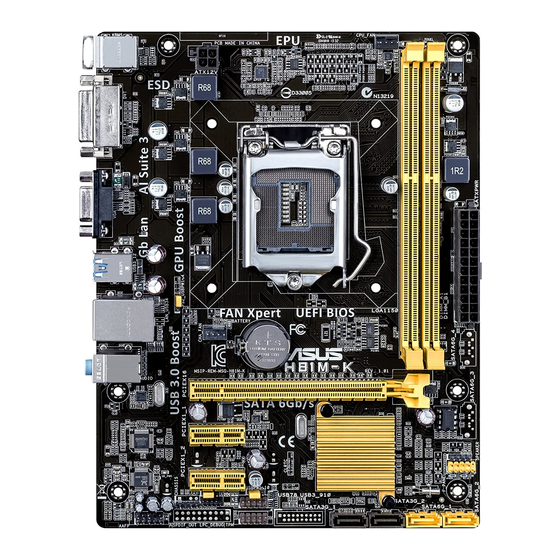
ASUS H81M-K motherboard |
|
|
Cables |
2 x Serial ATA 6.0 Gb/s cables |
|
|
Accessories |
1 x I/O Shield |
|
|
Application DVD |
Support DVD |
|
|
Documentation |
User Guide |
|
If any of the above items is damaged or missing, contact your retailer.
H81M-K specifications summary
CPU
Chipset
Memory
Graphics
Expansion slots
Storage
LGA1150 socket for Intel® 4th Generation CoreTM i7/ i5 / i3, Pentium® and Celeron® Processors
Supports 22nm CPU
Supports Intel® Turbo Boost Technology 2.0*
*Intel® Turbo Boost Technology 2.0 support depends on the CPU types.
**Refer to www.asus.com for Intel® CPU support list.
Intel® H81 Express Chipset
2 x DIMMs, max. 16GB DDR3 1600/1333/1066MHz, non-ECC, unbuffered memory modules
Dual-channel memory architecture
Supports Intel® Extreme Memory Profile (XMP)
*Hyper DIMM support is subject to the physical characteristics of individual CPUs. Please refer to Memory QVL for details.
**Refer to www.asus.com for the latest Memory QVL (Qualified Vendors List).
***Due to Intel® chipset limitations, DDR3 1600MHz and higher memory modules on XMP mode will run at the maximum transfer rate of DDR3 1600MHz.
Integrated Graphics Processor — Intel® HD Graphics support Multi-VGA output support: DVI-D, RGB port
—Supports DVI-D with max. resolution up to 1920 x1200@60Hz
—Supports RGB with max. resolution 1920×1200@60Hz
—Maximum shared memory of 1024MB
1 x PCI Express x16 slot (at x16 mode, yellow) 2 x PCI Express x1 slots
Intel® H81 Express Chipset:
—2 x Serial ATA 6.0 Gb/s connectors (yellow)
—2 x Serial ATA 3.0 Gb/s connectors (dark brown)
—Supports Intel® Rapid Start Technology* and Intel® Smart Connect Technology**
*Due to the limitation of the Intel® H81 chipset, Intel® Rapid Start Technology can be configured only from the BIOS Setup program.
**These functions will work depending on the CPU installed.
(continued on the next page)
vi

H81M-K specifications summary
|
LAN |
Realtek® RTL8111G Gigabit LAN Controller |
|
|
Audio |
Realtek® ALC887 8-Channel High DefinitionAudio CODEC |
|
|
— Supports Jack-Detection and Front Panel Jack-Retasking |
USB
ASUS unique features
Back Panel I/O ports
Internal
I/O connectors/ buttons/switches
*Use a chassis with HD audio module in the front panel to support an 8-channel audio output
Intel® H81 Express Chipset
—2 x USB 3.0/2.0 ports at rear panel (blue)*
—6 x USB 2.0/1.1 ports (4 ports at mid-board, 2 ports at the rear panel)
*Supports ASUS USB 3.0 Boost
ASUS Exclusive Features:
—ASUS EPU
—ASUS UEFI BIOS EZ Mode featuring a friendly graphical user interface
—ASUS USB 3.0 Boost
—ASUS AI Charger
—ASUS GPU Boost
—ASUS AI Suite 3
—ASUS Anti-surge Protection
—ASUS ESD
ASUS Quiet Thermal Solution
—ASUS Fanless Design: Stylish Heatsink solution
—ASUS Fan Xpert
ASUS Q-Design
— ASUS Q-Slot
ASUS EZ DIY:
—ASUS CrashFree BIOS 3
—ASUS EZ Flash 2
1 x PS/2 keyboard port (purple)
1 x PS/2 mouse port (green)
2 x USB 3.0/2.0 ports
2 x USB 2.0/1.1 ports
1 x DVI port
1 x D-Sub port
1 x LAN (RJ-45) port
3 x Audio jacks support 8-channel audio output
2 x USB 2.0/1.1 connectors support additional 4 USB 2.0/1.1 ports 2 x SATA 6.0Gb/s connectors
2 x SATA 3.0Gb/s connectors
1 x CPU fan connector
1 x Chassis fan connector
1 x Front panel audio connector
1 x S/PDIF Out connector
1 x 24-pin EATX power connector
1 x 4-pin EATX 12V power connector
1 x Speaker connector
1 x System panel connector
1 x CLRTC jumper
(continued on the next page)
vii

H81M-K specifications summary
BIOS features
Manageability
Support DVD
Operating System Support
Form factor
64 Mb Flash ROM, UEFI AMI BIOS, PnP, DMI2.0, WfM 2.0, SM BIOS 2.7, ACPI 2.0a, Multi-language BIOS, ASUS EZ Flash 2, ASUS CrashFree
BIOS 3, My Favorites, Quick Note, Last Modified Log, F12 PrintScreen, F3
Shortcut functions and ASUS DRAM SPD (Serial Presence Detect) memory information
WfM 2.0, DMI 2.0, WOL by PME, PXE
Drivers
ASUS utilities
EZ Update
Anti-virus software (OEM version)
Windows® 8
Windows® 7
uATX form factor: 8.9 in x 6.9 in (22.6 cm x 17.5 cm)
Specifications are subject to change without notice.
viii
Product introduction |
1 |
1.1Before you proceed
Take note of the following precautions before you install motherboard components or change any motherboard settings.
• Unplug the power cord from the wall socket before touching any component.
• Before handling components, use a grounded wrist strap or touch a safely grounded object or a metal object, such as the power supply case, to avoid damaging them due to static electricity.
•Hold components by the edges to avoid touching the ICs on them.
•Whenever you uninstall any component, place it on a grounded antistatic pad or in the bag that came with the component.
•Before you install or remove any component, ensure that the ATX power supply is switched off or the power cord is detached from the power supply. Failure to do so may cause severe damage to the motherboard, peripherals, or components.
1.2Motherboard overview
Before you install the motherboard, study the configuration of your chassis to ensure that the motherboard fits into it.
Ensure that you unplug the power cord before installing or removing the motherboard. Failure to do so can cause you physical injury and damage motherboard components.
1.2.1Placement direction
When installing the motherboard, ensure that you place it into the chassis in the correct orientation. The edge with external ports goes to the rear part of the chassis as indicated in the image below.

1.2.2Screw holes
Place six screws into the holes indicated by circles to secure the motherboard to the chassis.
Do not overtighten the screws! Doing so can damage the motherboard.
|
Place this side towards |
|
the rear of the chassis |
H81M-K
|
1-2 |
Chapter 1: Product introduction |
![]()
1.2.3Motherboard layout
|
1 |
2 |
3 |
4 |
3 |
5 |
KBMS
DVI
VGA
USB3_12
LAN_USB34

 PS2_USBPW1-4
17.5cm(6.9in)
ASP
ATX12V 1225
LGA1150
CHA_FAN
CPU_FAN 


|
DDR3 DIMM A1 (64bit, 240-pin module) DDR3 DIMM B1 (64bit, 240-pin module) |
EATXPWR |
22.6cm(8.9in) |
2
|
BATTERY |
|
|
AUDIO |
H81M-K |
|
PCIEX16 |
|
|
RTL |
|
|
8111G |
|
SB_PWR |
|
|
ALC |
PCIEX1_2 |
|
887VD2 |
|
|
CLRTC |
|
|
SPDIF_OUT |
|
|
AAFP |
|
64Mb |
||
|
BIOS |
||
|
Intel® |
6 |
|
|
SPEAKER |
||
|
H81 |
7 |
|
|
F_PANEL |
||
|
USBPW5-10 |
||
|
USB56 |
SATA3G_1 SATA3G_2 |
SATA6G_1 SATA6G_2 |


 USB78
USB78
1.2.4Layout contents
|
Connectors/Jumpers/Slots/LED |
Page |
|
|
1. |
Keyboard and USB device wakeup (3-pin PS2_USBPW1~4) |
1-12 |
|
2. |
ATX power connectors (24-pin EATXPWR, 4-pin ATX12V) |
1-17 |
|
3. |
CPU and chassis fan connectors (4-pin CPU_FAN, 4-pin CHA_FAN) |
1-16 |
|
4. |
Intel® LGA1150 CPU socket |
1-4 |
|
5. |
DDR3 DIMM slots |
1-7 |
|
6. |
Speaker connector (4-pin SPEAKER) |
1-17 |
|
7. |
System panel connector (10-1 pin F_PANEL) |
1-19 |
|
8. |
Intel® H81 Serial ATA 6.0Gb/s connector (7-pin SATA6G_1~2 [yellow]) |
1-18 |
|
9. |
Intel® H81 Serial ATA 3.0Gb/s connector (7-pin SATA3G_1~2 [dark brown]) |
1-18 |
|
10. |
USB 2.0 connectors (10-1 pin USB78, USB56) |
1-16 |
|
11. |
USB device wake-up (3-pin USBPW) |
1-12 |
|
12. |
Clear RTC RAM (3-pin CLRTC) |
1-11 |
|
13. |
Digital audio connector (4-1 pin SPDIF_OUT) |
1-15 |
|
14. |
Front panel audio connector (10-1 pin AAFP) |
1-15 |
|
15. |
Onboard LED (SB_PWR) |
1-20 |
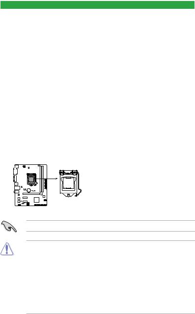
1.3Central Processing Unit (CPU)
This motherboard comes with a surface mount LGA1150 socket designed for the Intel® 4th generation Core™ i7 / Core™ i5 / Core™ i3, Pentium® and Celeron® processors.
H81M-K
H81M-K CPU socket LGA1150
Unplug all power cables before installing the CPU.
•Upon purchase of the motherboard, ensure that the PnP cap is on the socket and the socket contacts are not bent. Contact your retailer immediately if the PnP cap is missing, or if you see any damage to the PnP cap/socket contacts/motherboard components. ASUS will shoulder the cost of repair only if the damage is shipment/ transit-related.
•Keep the cap after installing the motherboard. ASUS will process Return Merchandise
Authorization (RMA) requests only if the motherboard comes with the cap on the
LGA1150 socket.
•The product warranty does not cover damage to the socket contacts resulting from incorrect CPU installation/removal, or misplacement/loss/incorrect removal of the PnP cap.
|
1-4 |
Chapter 1: Product introduction |

1.3.1Installing the CPU
1
A
B
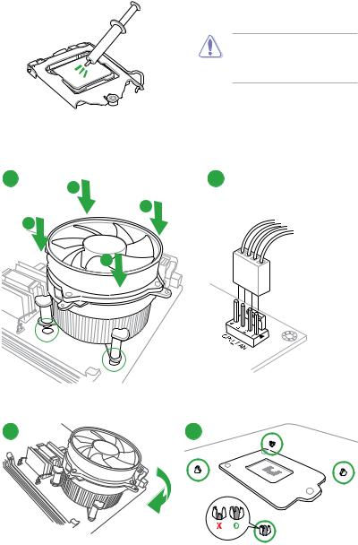
1.3.2CPU heatsink and fan assembly installation
Apply the Thermal Interface Material to the CPU heatsink and CPU before you install the heatsink and fan if necessary.
To install the CPU heatsink and fan assembly
B
B
A
|
1-6 |
Chapter 1: Product introduction |

To uninstall the CPU heatsink and fan assembly
|
1 |
2 |
A |
|
B |
B |
|
|
A |
1.4System memory
1.4.1Overview
This motherboard comes with two Double Data Rate 3 (DDR3) Dual Inline Memory Module (DIMM) sockets. A DDR3 module is notched differently from a DDR or DDR2 module. DO NOT install a DDR or DDR2 memory module to the DDR3 slot.
According to Intel® CPU spec, DIMM voltage below 1.65V is recommended to protect the CPU.
|
Channel |
Sockets |
|
Channel A |
DIMM_A1 |
|
Channel B |
DIMM_B1 |
H81M-K 240-pin DDR3 DIMM sockets
1.4.2Memory configurations
You may install 1GB, 2GB, 4GB, and 8GB unbuffered non ECC DDR3 DIMMs into the DIMM sockets.
 Loading…
-
Драйверы
53
-
Инструкции по эксплуатации
1

ASUS H81M-K инструкция по эксплуатации
(52 страницы)
- Языки:Французский
-
Тип:
PDF -
Размер:
5.48 MB -
Описание:
H81M-K user’s manual(French)
H81M-K user’s manual(French)
Просмотр
На NoDevice можно скачать инструкцию по эксплуатации для ASUS H81M-K. Руководство пользователя необходимо для ознакомления с правилами установки и эксплуатации ASUS H81M-K. Инструкции по использованию помогут правильно настроить ASUS H81M-K, исправить ошибки и выявить неполадки.