Посмотреть инструкция для Gigabyte GA-F2A88XM-DS2 бесплатно. Руководство относится к категории материнские платы, 1 человек(а) дали ему среднюю оценку 9.5. Руководство доступно на следующих языках: английский. У вас есть вопрос о Gigabyte GA-F2A88XM-DS2 или вам нужна помощь? Задайте свой вопрос здесь
Не можете найти ответ на свой вопрос в руководстве? Вы можете найти ответ на свой вопрос ниже, в разделе часто задаваемых вопросов о Gigabyte GA-F2A88XM-DS2.
Какая ширина Gigabyte GA-F2A88XM-DS2?
Какая толщина Gigabyte GA-F2A88XM-DS2?
Инструкция Gigabyte GA-F2A88XM-DS2 доступно в русский?
Не нашли свой вопрос? Задайте свой вопрос здесь
-
Страница 1
GA-F2A88XM-DS2 User’s Manual Rev . 3001 12ME-F288MS2-3001R[…]
-
Страница 2
Motherboard GA-F2A88XM-DS2 Aug. 30, 2013 Aug. 30, 2013 Motherboard GA-F2A88XM-DS2 Copyright © 2013 GIGA-BYTE TECHNOLOGY CO., L TD. All rights reserved. The trademarks mentioned in this manual are legally registered to their respective owners. Disclaimer Information in this manual is protected by copyright laws and is the property of GIGABYTE. Chan[…]
-
Страница 3
— 3 — T able of Contents GA-F2A88XM-DS2 Motherboard Layout ………………………………………………………………. 4 GA-F2A88XM-DS2 Motherboard Block Diagram …………………………………………………… 5 Chapter 1 Hardware Installation …………………………………………………………………….[…]
-
Страница 4
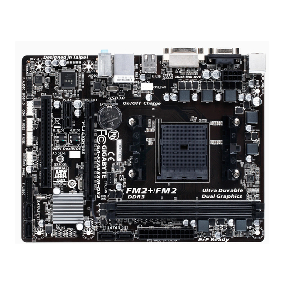
— 4 — GA-F2A88XM-DS2 Motherboard Layout The box contents above are for reference only and the actual items shall depend on the product package you obtain. The box contents are subject to change without notice. Box Contents 5 GA-F2A88XM-DS2 motherboard 5 Motherboard driver disk 5 T wo SA T A cables 5 User’s Manual 5 I/O Shield KB_MS_USB SYS_F A[…]
-
Страница 5
— 5 — For detailed product information/limitation(s), refer to «1-2 Product Specications.» GA-F2A88XM-DS2 Motherboard Block Diagram UMI PCI Bus 1 PCI PCI CLK (33 MHz) COM LPC Bus PS/2 KB/Mouse Dual BIOS 8 USB 2.0/1.1 4 SA T A 6Gb/s PCI Express Bus PCI Express Bus PCIe CLK (100 MHz) PCIe CLK (100 MHz) 1 PCI Express x1 x1 x1 LAN RJ45 APU[…]
-
Страница 6
— 6 — Chapter 1 Hardware Installation 1-1 Installation Precautions The motherboard contains numerous delicate electronic circuits and components which can become damaged as a result of electrostatic discharge (ESD). Prior to installation, carefully read the user’s manual and follow these procedures: • Prior to installation, make sure the cha[…]
-
Страница 7
— 7 — 1-2 ProductSpecications APU FM2+ Socket: — AMD A series processors — AMD Athlon ™ series processors ( Go to GIGABYTE’s website for the latest APU support list. ) Chipset AMD A88X Memory 2 x 1.5V DDR3 DIMM sockets supporting up to 64 GB of system memory * Due to a Windows 32-bit operat ing system limitati on, when m[…]
-
Страница 8
— 8 — USB Chipset: — 8 x USB 2.0/1.1 ports ( 4 ports on the back panel, 4 ports available through the internal USB headers ) Internal Connectors 1 x 24-pin A TX main power connector 1 x 8-pin A TX 12V power connector 4 x SA T A 6Gb/s connectors 1 x APU fan header 1 x system fan header 1 x front panel header 1 x front[…]
-
Страница 9
— 9 — Form Factor Micro A TX Form Factor; 22.5cm x 17.4cm * GIGABYTE reserves the right to make any changes to the product speci cations and product-related information without prior notice. * Please visit the Support & DownloadsUtility page on GIGABYTE’s website to check the supported operating system ( s ) for the software liste[…]
-
Страница 10
— 10 — 1-5 Installing an Expansion Card Read the following guidelines before you begin to install an expansion card: • Make sure the motherboard supports the expansion card. Carefully read the manual that came with your expansion card. • Always turn off the computer and unplug the power cord from the power outlet before installing an expansion […]
-
Страница 11
— 1 1 — (Note) The DVI-D port does not support D-Sub connection by adapter . D-Sub Port The D-Sub port supports a 15-pin D-Sub connector . Connect a monitor that supports D-Sub connection to this port. DVI-D Port (Note) The DVI-D port conforms to the DVI-D specication and supports a maximum resolution of 2560×1600. Connect a monitor that support[…]
-
Страница 12
— 12 — 1-8 Internal Connectors Read the following guidelines before connecting external devices: • First make sure your devices are compliant with the connectors you wish to connect. • Before installing the devices, be sure to turn off the devices and your computer . Unplug the power cord from the power outlet to prevent damage to the devices. […]
-
Страница 13
— 13 — 1/2) A TX_12V/A TX(2×412VPowerConnectorand2×12MainPowerConnector) With the use of the power connector , the power supply can supply enough stable power to all the components on the motherboard. Before connecting the power connector , rst make sure the power supply is turned off and all devices are properly in[…]
-
Страница 14
— 14 — 5) SA T A3 0/1/2/3 (SA T A 6Gb/s Connectors) The SA T A connectors conform to SA T A 6Gb/s standard and are compatible with SA T A 3Gb/s and SA T A 1.5Gb/s standard. Each SA T A connector supports a single SA T A device. The AMD A88X Chipset supports RAID 0, RAID 1, RAID 5, RAID 10, and JBOD. Refer to Chapter 3, «Conguring SA T A Har[…]
-
Страница 15
— 15 — 7) F_AUDIO(FrontPanel AudioHeader) The front panel audio header supports Intel High Denition audio (HD) and AC’97 audio. Y ou may connect your chassis front panel audio module to this header . Make sure the wire assignments of the module connector match the pin assignments of the motherboard header . Incorrect connecti[…]
-
Страница 16
— 16 — 13) CLR_CMOS(ClearCMOSJumper) Use this jumper to clear the BIOS conguration and reset the CMOS values to factory defaults. T o clear the CMOS values, use a metal object like a screwdriver to touch the two pins for a few seconds. • Always turn off your computer before clearing the CMOS values. • After system restart, go to […]
-
Страница 17
— 17 — Chapter2 BIOSSetup • Because BIOS ashing is potentially risky, if you do not encounter problems using the current version of BIOS, it is recommended that you not ash the BIOS. T o ash the BIOS, do it with caution. Inadequate BIOS ashing may result in system malfunction. • It is recommended that you not alter the defa[…]
-
Страница 18
— 18 — 2-2 M.I.T . Whether the system will work stably with the overclock/overvoltage settings you made is dependent on your overall system congurations. Incorrectly doing overclock/overvoltage may result in damage to CPU, chipset, or memory and reduce the useful life of these components. This page is for advanced users only and we recommend you[…]
-
Страница 19
— 19 — & Core Performance Boost (Note1) Allows you to determine whether to enable the Core Performance Boost (CPB) technology , a CPU performance-boost technology . (Default: Auto) & T urbo CPB (Note1) Allows you to determine whether to improve CPU performance. (Default: Disabled) & CPB Ratio (Note1) Allows you alter t[…]
-
Страница 20
— 20 — ` Channel A/B T iming Settings This sub-menu provides memory timing settings for each channel of memory . The respective timing setting screens are congurable only when DRAM Timing Selectable is set to Quick or Expert . Note: Y our system may become unstable or fail to boot after you make changes on the memory timings. If this occurs, ple[…]
-
Страница 21
— 21 — & System Fan Speed Control Allows you to determine whether to enable the fan speed control function and adjust the fan speed. N ormal Allows the fan to run at different speeds according to the system temperature. Y ou can adjust the fan speed with EasyTune based on your system requirements. (Default) Silent Allows the fan to run […]
-
Страница 22
— 22 — 2-4 BIOSFeatures & BootOptionPriorities Species the overall boot order from the available devices. For example, you can set hard drive as the rst priority ( Boot Option#1 ) and DVD ROM drive as the second priority ( BootOption #2 ). The list only displays the device with the highest priority for a specic […]
-
Страница 23
— 23 — & CSM Support Enables or disables UEFI CSM (Compatibility Support Module) to support a legacy PC boot process. Always Enables UEFI CSM. (Default) Never Disables UEFI CSM and supports UEFI BIOS boot process only . This item is congurable only when OST ype is set to Windows 8. & Boot Mode Selection Allows you to select wh[…]
-
Страница 24
— 24 — 2-5 Peripherals & IOMMU Enables or disables AMD IOMMU support. (Default: Enabled) & OnChipSA T AChannel Enables or disables the integrated SA T A controllers. (Default: Enabled) & OnChipSA T AT ype Enables or disables RAID for the SA T A controllers integrated in the Chipset or congures the SA T A controllers to AH[…]
-
Страница 25
— 25 — & EHCI Hand-off Determines whether to enable EHCI Hand-off feature for an operating system without EHCI Hand-off support. (Default: Disabled) & Port 60/64 Emulation Enables or disables emulation of I/O ports 64h and 60h. This should be enabled for full legacy support for USB keyboards/mice in MS-DOS or in operating system that does n[…]
-
Страница 26
— 26 — 2-6 Power Management & Resume by Alarm Determines whether to power on the system at a desired time. (Default: Disabled) If enabled, set the date and time as following: Wake up day: T urn on the system at a specic time on each day or on a specic day in a month. Wake up hour/minute/second: Set the time at which the system wil[…]
-
Страница 27
— 27 — & PowerOnPassword Set the password when PowerOnByKeyboard is set to Password . Press <Enter> on this item and set a password with up to 5 characters and then press <Enter> to accept. T o turn on the system, enter the password and press <Enter>. Note: T o cancel the password, press <Enter> on this it[…]
-
Страница 28
— 28 — & BootOverride Allows you to select a device to boot immediately . Press <Enter> on the device you select and select Ye s to conrm. Y our system will restart automatically and boot from that device. & SaveProles This function allows you to save the current BIOS settings to a prole. Y ou can create up to 8 prol[…]
-
Страница 29
— 29 — Before you begin • At least two SA T A hard drives (to ensure optimal performance, it is recommended that you use two hard drives with identical model and capacity). If you do not want to create RAID, you may prepare only one hard drive. • Windows 8/7/XP (32-bit) setup disk. • Motherboard driver disk. • A USB ash drive. • A USB […]
-
Страница 30
— 30 — Ex am pl e 1: Creat e a R A I D 0 ar ra y wi th D r ive 0 a nd D ri ve 1 a nd t he a rr ay si z e is 4 0 GB . rcadm -C -r0 -d 0 1 -s 40000 ( «C» = Create a array , «r0″=RAID 0, d 0 1=Drive 0 and Drive 1, «s 40000″=Size of 40 GB; to use the maximum size allowed, do not enter » s x0000 «) Ex am pl e 2: C[…]
-
Страница 31
— 31 — InstallingtheSA T ARAID/AHCIDriverandOperatingSystem With the correct BIOS settings, you are ready to install the operating system. A. Installing Windows 8/7 (The following instructions use Windows 8 as the example operating system.) Step 1: Y ou need to install the SA T A RAID/AHCI driver during the OS installation. Use[…]
-
Страница 32
— 32 — After inserting the driver disk, «Xpress Install» will automatically scan your system and then list all the drivers that are recommended to install. Y ou can click the Install All button and «Xpress Install» will install all the recommended drivers. Or click Install Single Items to manually select the drivers you wish to […]
-
Страница 33
— 33 — Regulatory Statements RegulatoryNo tices This document must not be copied without our written permission, and the contents there of must not be imparted to a third party nor be used for any unauthorized purpose. Contravention will be prosecuted. We believe that the information contained herein was accurate in all respects at the time of p[…]
-
Страница 34
— 34 -[…]
-
Страница 35
— 35 -[…]
-
Страница 36
— 36 — GIGA-BYTETECHNOLOGYCO.,L TD. Add re ss: N o.6 , Bao C hia ng Ro ad, H si n-Ti en D ist ., New Taipe i Cit y 2 31, T a iwa n TEL: + 88 6 -2- 8912- 40 0 0, FA X: + 88 6 -2- 8912- 40 0 5 T e ch . and N on -T e ch. S upp or t (Sal es / Mar ket in g) : htt p://gg ts .gi gaby t e.co m.t w WEB a ddr es s (En gli sh): ht tp:// w w w.gi ga b[…]
-
Страница 37
[…]
-
Страница 38
English more information and for the voice mail number , contact your service provider . 1. Press Menu Settings Calls V oice mail . 2. Select Empty Add . 3. Select Phonebook to add a contact from the Phonebook. Alternatively , select Manual . See Phonebook, p.13 . 4. Press OK to conrm. T o edit or delete an existing entry , select it and press O[…]
-
Страница 39
[…]
-
Страница 40
[…]
-
Страница 41
[…]
-
Страница 42
[…]
-
Страница 43
English 2. Select SMS centre Edit . 3. Enter the service centre number . Press Clear to delete. 4. Press OK to conrm. Cell broadcast Y ou can receive messages on various topics from your service provider , such as weather or trafc conditions in a particular region. For available channels and relevant channel settings, contact your service pro[…]
-
Страница 44
[…]
-
Страница 45
[…]
-
Страница 46
English Delivery report Y ou can select if you want the phone to notify you when your text message or picture message has reached the receiver . 1. Press Menu Settings Messages . 2. Select Delivery report On / Off to enable/disable. 3. Press OK to conrm. Note! If you choose Delivery report = On , some operators will charge you for that message. […]
-
Страница 47
[…]
-
Страница 48
English • Off the phone dials without sending a text message rst. 3. Press OK to conrm. Message 1. Press Menu Settings Assistance SMS . 2. Select Message Edit to write the message. 3. Press OK to conrm. Note! Y ou must write a message if you activate the SMS function. Conrm with «0» When the assistance function is activated […]
-
Страница 49
[…]
-
Страница 50
[…]
-
Страница 51
English • Account name to enter the account name. • APN to enter the APN address. • User name to enter user name. • Password to enter password • Connection type select HTTP / W AP . • Proxy address to enter proxy address. • Proxy port to enter proxy port. • User name to enter user name. • Password to enter password. 4. Press Done […]
-
Страница 52
English • On to activate PIN code, you need to enter the PIN code every time the phone is started. • Off to deactivate PIN code. W arning, if SIM card is lost/stolen it is unprotected. • Automatic to not enter the PIN code when the phone is started, the phone remembers it automatically . If the SIM card is moved to another phone (lost/stolen)[…]
-
Страница 53
English 2. Select Number list Empty Add . 3. Select Phonebook to add a contact from it. Alternatively , press Manual . 4. Press . 5. Enter the number and press OK to conrm. 6. Repeat until you have 5 contacts (maximum). T o edit or delete an existing entry , select it and press Options View / Edit / Delete . Fixed dial (FDN) Y ou can limit calls[…]
- Manuals
- Brands
- Gigabyte Manuals
- Motherboard
- GA-F2A88XM-DS2
- User manual
-
Contents
-
Table of Contents
-
Bookmarks
Quick Links
GA-F2A88XM-DS2
User’s Manual
Rev. 3001
12ME-F288MS2-3001R
Related Manuals for Gigabyte GA-F2A88XM-DS2
Summary of Contents for Gigabyte GA-F2A88XM-DS2
-
Page 1
GA-F2A88XM-DS2 User’s Manual Rev. 3001 12ME-F288MS2-3001R… -
Page 2
The trademarks mentioned in this manual are legally registered to their respective owners. Disclaimer Information in this manual is protected by copyright laws and is the property of GIGABYTE. No part of this manual may be reproduced, copied, translated, transmitted, or published in any form or by any means without GIGABYTE’s prior written permission. -
Page 3: Table Of Contents
Table of Contents GA-F2A88XM-DS2 Motherboard Layout ……………..4 GA-F2A88XM-DS2 Motherboard Block Diagram …………5 Chapter 1 Hardware Installation ………………6 Installation Precautions ………………6 ………………7 Installing the APU ………………… 9 Installing the Memory ………………9 Installing an Expansion Card …………….. 10 ……….10 Back Panel Connectors ………………
-
Page 4: Ga-F2A88Xm-Ds2 Motherboard Layout
GA-F2A88XM-DS2 Motherboard Layout KB_MS_USB ATX_12V Socket FM2+ CPU_FAN R_USB USB30_LAN SYS_FAN Realtek ® GbE LAN GA-F2A88XM-DS2 AUDIO PCIEX16 PCIEX1 M_BIOS ® AMD A88X Super I/O B_BIOS CODEC F_USB30 SATA3 CLR_CMOS F_AUDIO SPDIF_O F_USB2 F_USB1 F_PANEL Box Contents GA-F2A88XM-DS2 motherboard Motherboard driver disk…
-
Page 5: Ga-F2A88Xm-Ds2 Motherboard Block Diagram
GA-F2A88XM-DS2 Motherboard Block Diagram 1 PCI Express x16 Dual Channel Memory PCIe CLK AMD APU DVI-D D-Sub PCI Express Bus Dual BIOS 1 PCI Express x1 RJ45 Realtek ® PCIe CLK GbE LAN 4 SATA 6Gb/s 4 USB 3.0/2.0 AMD A88X PCI Express Bus 8 USB 2.0/1.1…
-
Page 6: Chapter 1 Hardware Installation
Chapter 1 Hardware Installation Installation Precautions The motherboard contains numerous delicate electronic circuits and components which can become manual and follow these procedures: Prior to installation, make sure the chassis is suitable for the motherboard. warranty sticker provided by your dealer. These stickers are required for warranty validation. Always remove the AC power by unplugging the power cord from the power outlet before installing or removing the motherboard or other hardware components.
-
Page 7
* The maximum 64 GB of system memory can be supported using 16 GB or above memory modules. GIGABYTE will update the memory support list on the of cial website when the memory modules are available on the market. -
Page 8
® Software Operating Support for Windows 8.1/8/7 32-bit/64-bit * If you plan to install Windows 8.1, please download the latest drivers from GIGABYTE’s System website. Support for Windows XP 32-bit * To support Windows XP 32-bit, you must install an AMD FM2 Trinity APU. -
Page 9: Installing The Apu
Form Factor Micro ATX Form Factor; 22.5cm x 17.4cm * GIGABYTE reserves the right to make any changes to the product speci cations and product-related information without prior notice. * Please visit the Support & Downloads\Utility page on GIGABYTE’s website to check the supported operating system s for the software listed in the «Unique Features»…
-
Page 10: Installing An Expansion Card
Due to APU limitations, read the following guidelines before installing the memory in Dual Channel mode. Dual Channel mode cannot be enabled if only one DDR3 memory module is installed. When enabling Dual Channel mode with two memory modules, it is recommended that memory of the same capacity, brand, speed, and chips be used.
-
Page 11
D-Sub Port The D-Sub port supports a 15-pin D-Sub connector. Connect a monitor that supports D-Sub connection to this port. DVI-D Port Connect a monitor that supports DVI-D connection to this port. Please note that the actual resolutions supported are dependent on the monitor being used and support for 2560×1600 resolution requires both a monitor and cable that support Dual Link DVI. -
Page 12: Internal Connectors
Internal Connectors ATX_12V SPDIF_ F_USB30 CPU_FA F_USB1/F_USB2 SYS_FA SATA3 0/1/2/3 F_PA EL CLR_CM S F_AUDI Read the following guidelines before connecting external devices: First make sure your devices are compliant with the connectors you wish to connect. Before installing the devices, be sure to turn off the devices and your computer. Unplug the power cord from the power outlet to prevent damage to the devices.
-
Page 13
With the use of the power connector, the power supply can supply enough stable power to all the components off and all devices are properly installed. The power connector possesses a foolproof design. Connect the power supply cable to the power connector in the correct orientation. The 12V power connector mainly supplies power to the APU. -
Page 14
5) SATA3 0/1/2/3 (SATA 6Gb/s Connectors) The SATA connectors conform to SATA 6Gb/s standard and are compatible with SATA 3Gb/s and SATA 1.5Gb/s standard. Each SATA connector supports a single SATA device. The AMD A88X Chipset supports Pin No. SATA3 SATA3 are to be used, the total number of hard drives must be an even number. -
Page 15
your chassis front panel audio module to this header. Make sure the wire assignments of the module connector match the pin assignments of the motherboard header. Incorrect connection between the module connector and the motherboard header will make the device unable to work or even damage it. For HD Front Panel Audio: For AC’97 Front Panel Audio: Pin No. -
Page 16
optional USB bracket. For purchasing the optional USB bracket, please contact the local dealer. Pin No. Pin No. USB DY+ USB DX- USB DY- No Pin USB DX+ Prior to installing the USB bracket, be sure to turn off your computer and unplug the power cord from the power outlet to prevent damage to the USB bracket. -
Page 17: Chapter 2 Bios Setup
To access the BIOS Setup program, press the <Delete> key during the POST when the power is turned on. To upgrade the BIOS, use either the GIGABYTE Q-Flash or @BIOS utility. Q-Flash allows the user to quickly and easily upgrade or back up BIOS without entering the operating system.
-
Page 18
M.I.T. This section provides information on the BIOS version, CPU base clock, CPU frequency, memory frequency, Whether the system will work stably with the overclock/overvoltage settings you made is dependent on your overall and reduce the useful life of these components. This page is for advanced users only and we recommend you not to M.I.T. -
Page 19
Core Performance Boost Turbo CPB CPB Ratio Allows you alter the ratio for the CPB. The adjustable range is dependent on the CPU being installed. Cool&Quiet Enabled Lets the AMD Cool’n’Quiet driver dynamically adjust the CPU clock and VID to reduce Disabled Disables this function. -
Page 20
DRAM Timing Selectable Quick and Expert Quick, Expert. When using a non-XMP memory module or is set to Disabled, this item will display as 1.50V. When is set to , this item will display the value based on the SPD data on the XMP memory. The value displayed here is dependent on the CPU being used. -
Page 21: System Information
System Fan Speed Control Allows you to determine whether to enable the fan speed control function and adjust the fan speed. Normal Allows the fan to run at different speeds according to the system temperature. You can adjust Silent Allows the fan to run at slow speeds. Manual Allows you to control the fan speed under the Slope PWM item.
-
Page 22: Bios Features
A password is only required for entering the BIOS Setup program. System A password is required for booting the system and for entering the BIOS Setup Allows you to determine whether to display the GIGABYTE Logo at system startup. Disabled skips the — 22 -…
-
Page 23
CSM Support Never Disables UEFI CSM and supports UEFI BIOS boot process only. is set to Windows 8. Boot Mode Selection Allows you to select which type of operating system to boot. UEFI and Legacy Allows booting from operating systems that support legacy option ROM or UEFI Legacy Only Allows booting from operating systems that only support legacy Option ROM. -
Page 24: Peripherals
Peripherals to AHCI mode. RAID Enables RAID for the SATA controller. HD Audio Azalia Device If you wish to install a 3rd party add-in audio card instead of using the onboard audio, set this item to Disabled. If you wish to install a 3rd party add-in network card instead of using the onboard LAN, set this item to Disabled.
-
Page 25
EHCI Hand-off Determines whether to enable EHCI Hand-off feature for an operating system without EHCI Hand-off Port 60/64 Emulation Enables or disables emulation of I/O ports 64h and 60h. This should be enabled for full legacy support for USB keyboards/mice in MS-DOS or in operating system that does not natively support USB devices. Default: Disabled USB Storage Devices Displays a list of connected USB mass storage devices. -
Page 26: Power Management
Power Management Resume by Alarm If enabled, set the date and time as following: Wake up hour/minute/second: Set the time at which the system will be powered on automatically. Note: When using this function, avoid inadequate shutdown from the operating system or removal of the AC power, or the settings may not be effective.
-
Page 27: Save & Exit
Set the password when is set to Password. Press <Enter> on this item and set a password with up to 5 characters and then press <Enter> to accept. To turn on the system, enter the password and press <Enter>. Note: To cancel the password, press <Enter> on this item. When prompted for the password, press <Enter> again without entering the password to clear the password settings.
-
Page 28
Allows you to select a device to boot immediately. Press <Enter> on the device you select and select Yes Select File in HDD/USB/FDD If your system becomes unstable and you have loaded the BIOS default settings, you can use this function Select File in HDD/USB/FDD automatically created by the BIOS, such as reverting the BIOS settings to the last settings that worked… -
Page 29: Chapter 3 Appendix
Chapter 3 Appendix Before you begin Motherboard driver disk. Attach one end of the SATA signal cable to the rear of the SATA hard drive and the other end to available SATA port on the motherboard. Then connect the power connector from your power supply to the hard drive. refer to Chapter 2, «BIOS Setup,»…
-
Page 30
Example 1: Create a RAID 0 array with Drive 0 and Drive 1 and the array size is 40 GB. rcadm -C -r0 -d 0 1 -s 40000 («C»= s x0000 Example 2: Create a RAID 5 array with Drive 1 4 and the array size is 75 GB. rcadm -C -r5 -d 1 2 3 4 -s 75000 («C»= After you create the array, you can enter the «rcadm -M -qa»… -
Page 31
With the correct BIOS settings, you are ready to install the operating system. A. Installing Windows 8/7 Step 1: You need to install the SATA RAID/AHCI driver during the OS installation. Use an alternative system to copy Hw8_A88 folder under BootDrv in the driver disk. Step 2: Boot from the Windows 8 setup disk and perform standard OS installation steps. -
Page 32: Drivers Installation
Drivers Installation After installing the operating system, insert the motherboard driver disk into your optical drive. Click on the message «Tap to choose what happens with this disc» on the top-right corner of the screen and select «Run Run After inserting the driver disk, «Xpress Install» will automatically scan your system and then list all the drivers that are recommended to install.
-
Page 33: Regulatory Statements
Contravention will be prosecuted. We believe that the information contained herein was accurate in all respects at the time of printing. GIGABYTE cannot, however, assume any responsibility for errors or omissions in this text. Also note that the information in this document is subject to change without notice and should not be construed as a commitment by GIGABYTE.
-
Page 34
— 34 -… -
Page 35
— 35 -… -
Page 36: Contact Us
Address: No.6, Bao Chiang Road, Hsin-Tien Dist., New Taipei City 231,Taiwan TEL: +886-2-8912-4000, FAX: +886-2-8912-4005 You may go to the GIGABYTE website, select your language in the language list on the top right corner of the website. GIGABYTE Global Service System question, please link to: http://ggts.gigabyte.com.tw…
-
Драйверы
17
-
Инструкции по эксплуатации
4
Языки:

Gigabyte GA-F2A88XM-DS2 инструкция по эксплуатации
(36 страниц)
- Языки:Английский
-
Тип:
PDF -
Размер:
11.55 MB
Просмотр

Gigabyte GA-F2A88XM-DS2 инструкция по эксплуатации
(36 страниц)
- Языки:Английский
-
Тип:
PDF -
Размер:
11.06 MB
Просмотр

Gigabyte GA-F2A88XM-DS2 инструкция по эксплуатации
(36 страниц)
- Языки:Китайский
-
Тип:
PDF -
Размер:
11.85 MB
Просмотр

Gigabyte GA-F2A88XM-DS2 инструкция по эксплуатации
(36 страниц)
- Языки:Китайский
-
Тип:
PDF -
Размер:
11.57 MB
Просмотр
На NoDevice можно скачать инструкцию по эксплуатации для Gigabyte GA-F2A88XM-DS2. Руководство пользователя необходимо для ознакомления с правилами установки и эксплуатации Gigabyte GA-F2A88XM-DS2. Инструкции по использованию помогут правильно настроить Gigabyte GA-F2A88XM-DS2, исправить ошибки и выявить неполадки.
GIGABYTE
GA-F2A88XM-DS2 (rev. 3.0) Руководство по эксплуатации
Популярность:
3212 просмотры
Подсчет страниц:
36 страницы
Тип файла:
Размер файла:
11.06 Mb
-
Страница 1
GA-F2A88XM-DS2 User’s Manual Rev . 3001 12ME-F288MS2-3001R[…]
-
Страница 2
Motherboard GA-F2A88XM-DS2 Aug. 30, 2013 Aug. 30, 2013 Motherboard GA-F2A88XM-DS2 Copyright © 2013 GIGA-BYTE TECHNOLOGY CO., L TD. All rights reserved. The trademarks mentioned in this manual are legally registered to their respective owners. Disclaimer Information in this manual is protected by copyright laws and is the property of GIGABYTE. Chan[…]
-
Страница 3
— 3 — T able of Contents GA-F2A88XM-DS2 Motherboard Layout ………………………………………………………………. 4 GA-F2A88XM-DS2 Motherboard Block Diagram …………………………………………………… 5 Chapter 1 Hardware Installation …………………………………………………………………….[…]
-
Страница 4
— 4 — GA-F2A88XM-DS2 Motherboard Layout The box contents above are for reference only and the actual items shall depend on the product package you obtain. The box contents are subject to change without notice. Box Contents 5 GA-F2A88XM-DS2 motherboard 5 Motherboard driver disk 5 T wo SA T A cables 5 User’s Manual 5 I/O Shield KB_MS_USB SYS_F A[…]
-
Страница 5
— 5 — For detailed product information/limitation(s), refer to «1-2 Product Specications.» GA-F2A88XM-DS2 Motherboard Block Diagram UMI PCI Bus 1 PCI PCI CLK (33 MHz) COM LPC Bus PS/2 KB/Mouse Dual BIOS 8 USB 2.0/1.1 4 SA T A 6Gb/s PCI Express Bus PCI Express Bus PCIe CLK (100 MHz) PCIe CLK (100 MHz) 1 PCI Express x1 x1 x1 LAN RJ45 APU[…]
-
Страница 6
— 6 — Chapter 1 Hardware Installation 1-1 Installation Precautions The motherboard contains numerous delicate electronic circuits and components which can become damaged as a result of electrostatic discharge (ESD). Prior to installation, carefully read the user’s manual and follow these procedures: • Prior to installation, make sure the cha[…]
-
Страница 7
— 7 — 1-2 ProductSpecications APU FM2+ Socket: — AMD A series processors — AMD Athlon ™ series processors ( Go to GIGABYTE’s website for the latest APU support list. ) Chipset AMD A88X Memory 2 x 1.5V DDR3 DIMM sockets supporting up to 64 GB of system memory * Due to a Windows 32-bit operat ing system limitati on, when m[…]
-
Страница 8
— 8 — USB Chipset: — 8 x USB 2.0/1.1 ports ( 4 ports on the back panel, 4 ports available through the internal USB headers ) Internal Connectors 1 x 24-pin A TX main power connector 1 x 8-pin A TX 12V power connector 4 x SA T A 6Gb/s connectors 1 x APU fan header 1 x system fan header 1 x front panel header 1 x front[…]
-
Страница 9
— 9 — Form Factor Micro A TX Form Factor; 22.5cm x 17.4cm * GIGABYTE reserves the right to make any changes to the product speci cations and product-related information without prior notice. * Please visit the Support & DownloadsUtility page on GIGABYTE’s website to check the supported operating system ( s ) for the software liste[…]
-
Страница 10
— 10 — 1-5 Installing an Expansion Card Read the following guidelines before you begin to install an expansion card: • Make sure the motherboard supports the expansion card. Carefully read the manual that came with your expansion card. • Always turn off the computer and unplug the power cord from the power outlet before installing an expansion […]
-
Страница 11
— 1 1 — (Note) The DVI-D port does not support D-Sub connection by adapter . D-Sub Port The D-Sub port supports a 15-pin D-Sub connector . Connect a monitor that supports D-Sub connection to this port. DVI-D Port (Note) The DVI-D port conforms to the DVI-D specication and supports a maximum resolution of 2560×1600. Connect a monitor that support[…]
-
Страница 12
— 12 — 1-8 Internal Connectors Read the following guidelines before connecting external devices: • First make sure your devices are compliant with the connectors you wish to connect. • Before installing the devices, be sure to turn off the devices and your computer . Unplug the power cord from the power outlet to prevent damage to the devices. […]
-
Страница 13
— 13 — 1/2) A TX_12V/A TX(2×412VPowerConnectorand2×12MainPowerConnector) With the use of the power connector , the power supply can supply enough stable power to all the components on the motherboard. Before connecting the power connector , rst make sure the power supply is turned off and all devices are properly in[…]
-
Страница 14
— 14 — 5) SA T A3 0/1/2/3 (SA T A 6Gb/s Connectors) The SA T A connectors conform to SA T A 6Gb/s standard and are compatible with SA T A 3Gb/s and SA T A 1.5Gb/s standard. Each SA T A connector supports a single SA T A device. The AMD A88X Chipset supports RAID 0, RAID 1, RAID 5, RAID 10, and JBOD. Refer to Chapter 3, «Conguring SA T A Har[…]
-
Страница 15
— 15 — 7) F_AUDIO(FrontPanel AudioHeader) The front panel audio header supports Intel High Denition audio (HD) and AC’97 audio. Y ou may connect your chassis front panel audio module to this header . Make sure the wire assignments of the module connector match the pin assignments of the motherboard header . Incorrect connecti[…]
-
Страница 16
— 16 — 13) CLR_CMOS(ClearCMOSJumper) Use this jumper to clear the BIOS conguration and reset the CMOS values to factory defaults. T o clear the CMOS values, use a metal object like a screwdriver to touch the two pins for a few seconds. • Always turn off your computer before clearing the CMOS values. • After system restart, go to […]
-
Страница 17
— 17 — Chapter2 BIOSSetup • Because BIOS ashing is potentially risky, if you do not encounter problems using the current version of BIOS, it is recommended that you not ash the BIOS. T o ash the BIOS, do it with caution. Inadequate BIOS ashing may result in system malfunction. • It is recommended that you not alter the defa[…]
-
Страница 18
— 18 — 2-2 M.I.T . Whether the system will work stably with the overclock/overvoltage settings you made is dependent on your overall system congurations. Incorrectly doing overclock/overvoltage may result in damage to CPU, chipset, or memory and reduce the useful life of these components. This page is for advanced users only and we recommend you[…]
-
Страница 19
— 19 — & Core Performance Boost (Note1) Allows you to determine whether to enable the Core Performance Boost (CPB) technology , a CPU performance-boost technology . (Default: Auto) & T urbo CPB (Note1) Allows you to determine whether to improve CPU performance. (Default: Disabled) & CPB Ratio (Note1) Allows you alter t[…]
-
Страница 20
— 20 — ` Channel A/B T iming Settings This sub-menu provides memory timing settings for each channel of memory . The respective timing setting screens are congurable only when DRAM Timing Selectable is set to Quick or Expert . Note: Y our system may become unstable or fail to boot after you make changes on the memory timings. If this occurs, ple[…]
-
Страница 21
— 21 — & System Fan Speed Control Allows you to determine whether to enable the fan speed control function and adjust the fan speed. N ormal Allows the fan to run at different speeds according to the system temperature. Y ou can adjust the fan speed with EasyTune based on your system requirements. (Default) Silent Allows the fan to run […]
-
Страница 22
— 22 — 2-4 BIOSFeatures & BootOptionPriorities Species the overall boot order from the available devices. For example, you can set hard drive as the rst priority ( Boot Option#1 ) and DVD ROM drive as the second priority ( BootOption #2 ). The list only displays the device with the highest priority for a specic […]
-
Страница 23
— 23 — & CSM Support Enables or disables UEFI CSM (Compatibility Support Module) to support a legacy PC boot process. Always Enables UEFI CSM. (Default) Never Disables UEFI CSM and supports UEFI BIOS boot process only . This item is congurable only when OST ype is set to Windows 8. & Boot Mode Selection Allows you to select wh[…]
-
Страница 24
— 24 — 2-5 Peripherals & IOMMU Enables or disables AMD IOMMU support. (Default: Enabled) & OnChipSA T AChannel Enables or disables the integrated SA T A controllers. (Default: Enabled) & OnChipSA T AT ype Enables or disables RAID for the SA T A controllers integrated in the Chipset or congures the SA T A controllers to AH[…]
-
Страница 25
— 25 — & EHCI Hand-off Determines whether to enable EHCI Hand-off feature for an operating system without EHCI Hand-off support. (Default: Disabled) & Port 60/64 Emulation Enables or disables emulation of I/O ports 64h and 60h. This should be enabled for full legacy support for USB keyboards/mice in MS-DOS or in operating system that does n[…]
-
Страница 26
— 26 — 2-6 Power Management & Resume by Alarm Determines whether to power on the system at a desired time. (Default: Disabled) If enabled, set the date and time as following: Wake up day: T urn on the system at a specic time on each day or on a specic day in a month. Wake up hour/minute/second: Set the time at which the system wil[…]
-
Страница 27
— 27 — & PowerOnPassword Set the password when PowerOnByKeyboard is set to Password . Press <Enter> on this item and set a password with up to 5 characters and then press <Enter> to accept. T o turn on the system, enter the password and press <Enter>. Note: T o cancel the password, press <Enter> on this it[…]
-
Страница 28
— 28 — & BootOverride Allows you to select a device to boot immediately . Press <Enter> on the device you select and select Ye s to conrm. Y our system will restart automatically and boot from that device. & SaveProles This function allows you to save the current BIOS settings to a prole. Y ou can create up to 8 prol[…]
-
Страница 29
— 29 — Before you begin • At least two SA T A hard drives (to ensure optimal performance, it is recommended that you use two hard drives with identical model and capacity). If you do not want to create RAID, you may prepare only one hard drive. • Windows 8/7/XP (32-bit) setup disk. • Motherboard driver disk. • A USB ash drive. • A USB […]
-
Страница 30
— 30 — Ex am pl e 1: Creat e a R A I D 0 ar ra y wi th D r ive 0 a nd D ri ve 1 a nd t he a rr ay si z e is 4 0 GB . rcadm -C -r0 -d 0 1 -s 40000 ( «C» = Create a array , «r0″=RAID 0, d 0 1=Drive 0 and Drive 1, «s 40000″=Size of 40 GB; to use the maximum size allowed, do not enter » s x0000 «) Ex am pl e 2: C[…]
-
Страница 31
— 31 — InstallingtheSA T ARAID/AHCIDriverandOperatingSystem With the correct BIOS settings, you are ready to install the operating system. A. Installing Windows 8/7 (The following instructions use Windows 8 as the example operating system.) Step 1: Y ou need to install the SA T A RAID/AHCI driver during the OS installation. Use[…]
-
Страница 32
— 32 — After inserting the driver disk, «Xpress Install» will automatically scan your system and then list all the drivers that are recommended to install. Y ou can click the Install All button and «Xpress Install» will install all the recommended drivers. Or click Install Single Items to manually select the drivers you wish to […]
-
Страница 33
— 33 — Regulatory Statements RegulatoryNo tices This document must not be copied without our written permission, and the contents there of must not be imparted to a third party nor be used for any unauthorized purpose. Contravention will be prosecuted. We believe that the information contained herein was accurate in all respects at the time of p[…]
-
Страница 34
— 34 -[…]
-
Страница 35
— 35 -[…]
-
Страница 36
— 36 — GIGA-BYTETECHNOLOGYCO.,L TD. Add re ss: N o.6 , Bao C hia ng Ro ad, H si n-Ti en D ist ., New Taipe i Cit y 2 31, T a iwa n TEL: + 88 6 -2- 8912- 40 0 0, FA X: + 88 6 -2- 8912- 40 0 5 T e ch . and N on -T e ch. S upp or t (Sal es / Mar ket in g) : htt p://gg ts .gi gaby t e.co m.t w WEB a ddr es s (En gli sh): ht tp:// w w w.gi ga b[…]
-
Страница 37
[…]
-
Страница 38
English more information and for the voice mail number , contact your service provider . 1. Press Menu Settings Calls V oice mail . 2. Select Empty Add . 3. Select Phonebook to add a contact from the Phonebook. Alternatively , select Manual . See Phonebook, p.13 . 4. Press OK to conrm. T o edit or delete an existing entry , select it and press O[…]
-
Страница 39
[…]
-
Страница 40
[…]
-
Страница 41
[…]
-
Страница 42
[…]
-
Страница 43
English 2. Select SMS centre Edit . 3. Enter the service centre number . Press Clear to delete. 4. Press OK to conrm. Cell broadcast Y ou can receive messages on various topics from your service provider , such as weather or trafc conditions in a particular region. For available channels and relevant channel settings, contact your service pro[…]
-
Страница 44
[…]
-
Страница 45
[…]
-
Страница 46
English Delivery report Y ou can select if you want the phone to notify you when your text message or picture message has reached the receiver . 1. Press Menu Settings Messages . 2. Select Delivery report On / Off to enable/disable. 3. Press OK to conrm. Note! If you choose Delivery report = On , some operators will charge you for that message. […]
-
Страница 47
[…]
-
Страница 48
English • Off the phone dials without sending a text message rst. 3. Press OK to conrm. Message 1. Press Menu Settings Assistance SMS . 2. Select Message Edit to write the message. 3. Press OK to conrm. Note! Y ou must write a message if you activate the SMS function. Conrm with «0» When the assistance function is activated […]
-
Страница 49
[…]
-
Страница 50
[…]
-
Страница 51
English • Account name to enter the account name. • APN to enter the APN address. • User name to enter user name. • Password to enter password • Connection type select HTTP / W AP . • Proxy address to enter proxy address. • Proxy port to enter proxy port. • User name to enter user name. • Password to enter password. 4. Press Done […]
-
Страница 52
English • On to activate PIN code, you need to enter the PIN code every time the phone is started. • Off to deactivate PIN code. W arning, if SIM card is lost/stolen it is unprotected. • Automatic to not enter the PIN code when the phone is started, the phone remembers it automatically . If the SIM card is moved to another phone (lost/stolen)[…]
-
Страница 53
English 2. Select Number list Empty Add . 3. Select Phonebook to add a contact from it. Alternatively , press Manual . 4. Press . 5. Enter the number and press OK to conrm. 6. Repeat until you have 5 contacts (maximum). T o edit or delete an existing entry , select it and press Options View / Edit / Delete . Fixed dial (FDN) Y ou can limit calls[…]