Американская компания Honeywell — крупнейший мировой разработчик автоматизированных систем для различных отраслей промышленности. Одно из ведущих направлений корпорации — создание решений для автоматической идентификации. В линейке представлены сканеры и терминалы сбора данных для разных сфер розничной торговли, функциональные высокоскоростные варианты техники для промышленной эксплуатации и складского учета. Рассмотрим универсальный сканер штрих-кода Honeywell 1450g, инструкцию по его настройке и эксплуатации, технические характеристики, преимущества и сферы применения.
Решим любые проблемы с вашим оборудованием!
Оставьте заявку и получите консультацию в течение 5 минут.
Voyager 1450g: инструкция и функциональные возможности
Honeywell (Metrologic) 1450g — бюджетный проводной фотосканер для считывания одномерных и двумерных штрихкодов. Ручной аппарат с функцией многоплоскостной обработки и адаптивным алгоритмом декодирования оперативно распознает 1D-, 2D- и PDF417-коды. Характеристики устройства:
- несколько разъемов для подключения к кассе и ПК: USB, RS-232, IBM 46xx (RS485), разрыв клавиатуры;
- удобство в эксплуатации: аппарат можно держать в руке или зафиксировать на подставке и использовать стационарно;
- полная совместимость со смарт-терминалами Эвотор и другими кассовыми аппаратами;
- считывание информации под разными углами на расстоянии до 55 см;
- работа в двух режимах: ручной — активация при нажатии на кнопку, презентационный — при наведении на штрихкод;
- световая и звуковая индикация.
Согласно инструкции, Хоневелл 1450g успешно справляется с обработкой поврежденных и низкокачественных этикеток, а также с расшифровкой графической информации с экранов смартфонов и ноутбуков, купонов, электронных билетов и интернет-кошельков.
Сферы применения
Сканер доказал свою эффективность и высокую производительность в разных сферах торговли и в складском обслуживании, но чаще всего он используется в мелкорозничной торговле, на кассовых узлах с умеренной проходимостью — до 200-250 человек в день. Технических возможностей устройства достаточно для автоматизации:
- минимаркетов, магазинов у дома;
- аптек;
- бутиков;
- павильонов с косметикой и парфюмерией;
- кафетериев, кофеен, закусочных и других предприятий общепита.
Работа со считывающим устройством не требует особых навыков и длительного обучения, достаточно ознакомиться с инструкцией Honeywell Metrologic 1450g и изучить краткое руководство пользователя. Metrologic соответствует требованиям ФСРАР, считывает алкогольные этикетки с PDF417, подходит для работы с информационной системой «Меркурий» (контроль над оборотом товаров животного происхождения) и ЕГАИС.
Это оптимальное решение для торговли меховыми изделиями и другими товарами, которые будут подключены к системе обязательной маркировки с июля 2019 года: обувь, сигареты, верхняя одежда, белье, духи и т. д. Стоимость устройства в зависимости от модификации и комплектации варьируется в пределах 4000-6300 рублей. Экономичная модель позволит перейти на новые требования законодательства с минимальными издержками.
Мы готовы помочь!
Задайте свой вопрос специалисту в конце статьи. Отвечаем быстро и по существу. К комментариям
Сканер Honeywell 1450g: инструкция по подключению к ПК и ККТ
Считывающее устройство можно подключить к стационарному ПК, ноутбуку, POS-системе, смарт-терминалу, мобильной или автономной кассе (только при считывании 1D-кодов). Режим эксплуатации, который необходимо выбрать в процессе настройки сканера, зависит от способа подключения. В инструкции к Voyager 1450g заявлено, что сканер поддерживает следующие типы подключения:
- Разрыв клавиатуры (RS/2). Шнур подключаемого устройства с таким интерфейсом заканчивается разветвлением: одна ветка — для клавиатуры, вторая — для ПК. При этом сам сканер подсоединяется к электросети через внешний аккумулятор. Такой способ позволяет освободить порты USB для другого оборудования. При считывании данные сразу вносятся в поле курсора, поэтому штрихкоды легко вводить в любую программу товароучета.
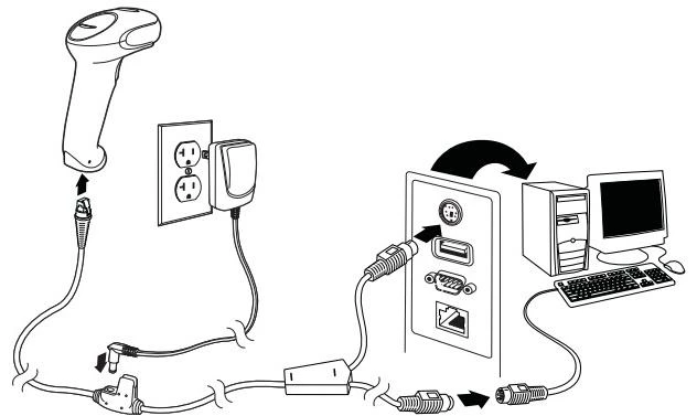
- COM-порт (RS-232). Распространенный вариант подсоединения для POS-систем. В современных ПК, ноутбуках и планшетах он, как правило, отсутствует. Такой тип интеграции требует подключения к электросети и установки драйвера.
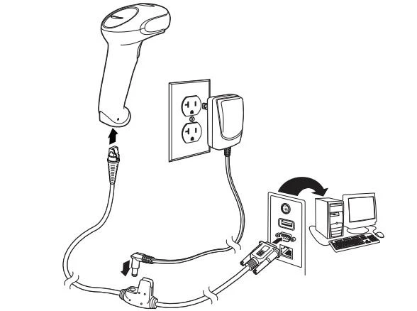
- RS485 (для интеграции с POS-оборудованием IBM).
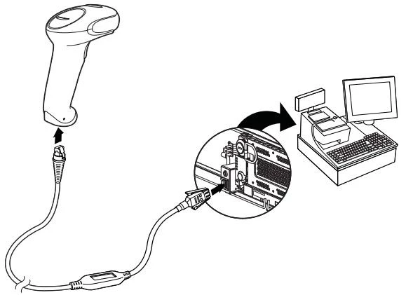
- USB (режим Hid Pos). Не требует подключения считывающего устройства к внешнему аккумулятору, поддерживается всеми современными ККТ. Данные штрихкода выводятся на ПК в позицию, где стоит курсор.
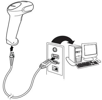
В инструкции к сканеру штрих-кода Хоневелл 1450g сказано, что модель поддерживает инновационную технологию PowerLink (Powerlink Cables), которая упрощает процесс замены кабелей и источников питания (коммутационные элементы можно быстро и безопасно заменить без специальных приспособлений).
Какой тип подключения выбрать
К смарт-терминалам и POS-моноблокам считывающее устройство подсоединяется через USB. В комплект поставки входит кабель длиной 3 м, который позволяет расположить устройства и интегрировать их между собой на любом удобном расстоянии. Для POS-систем рекомендовано подключение через RS-232 (если такой разъем есть в наличии). Это самый надежный и стабильно работающий интерфейс.
Выбор соединения также зависит от установленного программного обеспечения. Например, если на ПК стоит 1С, оптимальным выбором станет RS-232, поскольку с ним можно использовать бесплатную утилиту, входящую в состав 1С. Для ввода штрихкодов в текстовые редакторы или системы товароучета подойдет подключение через разрыв клавиатуры (RS/2).
Honeywell Metrologic 1450g: инструкция пользователя
Metrologic Voyager — фотосканер многоплоскостного считывания. Устройство необходимо расположить так, чтобы видоискатель спроецировал луч по центру штрихкода или в другом направлении, чтобы облегчить сканирование. Зафиксируйте пистолет напротив этикетки с кодом, нажмите кнопку и направьте луч на центральную часть изображения.
Чем ближе устройство к объекту, тем меньше луч, и наоборот. Для корректного и стремительного распознавания информации рекомендуется держать фотосканер ближе к мелким штрихкодам и дальше от крупных. Ламинированные поверхности имеют свойство отражать лучи, поэтому сканер лучше фиксировать под углом.
Важно! Перед подсоединением считывающего устройства необходимо выключить онлайн-кассу (компьютер).
Как настроить сканер штрих-кода Honeywell 1450g по инструкции
Аппарат легко программируется путем считывания специальных штрихкодов. Полный перечень закодированных команд для настройки можно найти в руководстве пользователя на официальном сайте производителя.
Чтобы подготовить новое считывающее устройство к эксплуатации, сбросьте заводские настройки и установите пользовательские параметры. Текущие настройки сбрасываются считыванием значка:
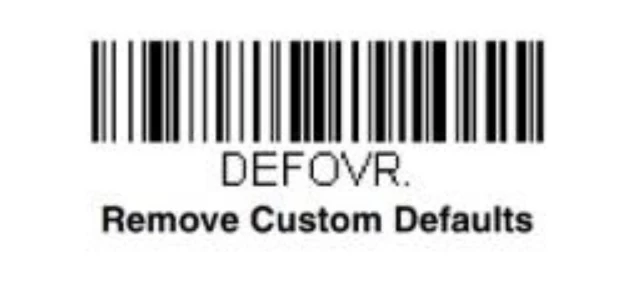
После этого устанавливаются заводские параметры:
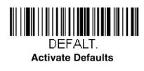
Дальнейшая процедура зависит от выбранного режима работы сканирующего устройства. При подключении по USB переведите сканер в режим HID POS:
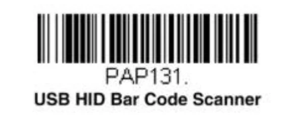
Работу в COM-режиме активируйте кодом:

Настройте разделительную полосу (специальный символ в линейных штрихкодах):
Далее необходимо открыть диспетчер устройств на ПК и проверить, появился ли в списке новый аппарат с интерфейсом COM.
Для клавиатурного режима потребуются дополнительные настройки для удобства ввода декодированной информации в 1С и другие товароучетные программы — добавление суффикса и префикса.
Префикс предназначен для того, чтобы каждый раз при считывании информации пользователю не приходилось открывать окно ввода штрихкода клавишей F1. Префикс делает это автоматически. Добавьте его в настройки последовательным сканированием следующих кодов:


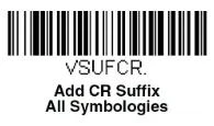
Запрограммированный суффикс возврата каретки позволяет не нажимать клавишу Enter после сканирования каждого штрихкода. Операция подтверждается автоматически. Чтобы добавить эту опцию в настройках, отсканируйте значок:

Далее активируйте функцию Control для правильной передачи непечатаемых знаков в операционную систему:
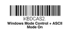
Порт RS485 используется крайне редко, только для интеграции с POS-терминалами IBM. Интерфейс настраивается кодом:
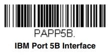
Следующие этапы программирования применимы для всех четырех режимов. Если фотосканер планируется использовать для работы с DataMatrix, например, для продажи маркированных товаров, необходимо включить опцию распознавания этого кода:

При необходимости активируйте режим непрерывного считывания. Эта опция полезна, например, при распознавании кодов с чеков заказа на кухне (в ресторане или кафе).

По умолчанию аппарат работает в режиме «Ручной запуск», когда для считывания достаточно нажать кнопку и поднести аппарат к товару. Чтобы включить режим «Презентационный», отсканируйте код:

Для возврата в «Ручной запуск»:

На этом базовая настройка завершена. Вы можете распечатать приведенные выше коды из инструкции к Honeywell 1450g или считывать их прямо с экрана вашего монитора.
Техническое сопровождение оборудования. Решим любые проблемы!
Оставьте заявку и получите консультацию в течение 5 минут.
Распространенные ошибки при сканировании
По умолчанию Metrologic 1450g настраивается на восьмизначный EAN. Если в товарной базе присутствуют иностранные сигареты с 7-значными кодами, фотосканер автоматически добавит перед расшифрованным значением цифру 0, но в кассе такой товар не найдется. Перенастройка осуществляется считыванием значка:

При обработке акцизных марок иногда выходит формат 136-*** вместо стандартного набора цифр и букв. Такое часто возникает из-за включенного режима сканирования DataMatrix. Для деактивации отсканируйте изображение:

Инструкция по настройке драйверов Honeywell 1450g
На официальном сайте Honeywell можно скачать драйверы для управления и оптимизации функциональных возможностей сканера. Выбор программы зависит от операционной системы и режима работы.
EZConfig for Scanning — бесплатная утилита, предназначенная для ускорения и упрощения эксплуатации считывающего устройства. После установки на ПК автоматически настраиваются префиксы и суффиксы (без использования вышеперечисленных настроечных штрихкодов). Программа поддерживает функцию автоматического обнаружения сканера независимо от типа интерфейса, в том числе через разрыв клавиатуры (такую схему выбирают 75 % пользователей). С помощью утилиты можно быстро изменить параметры или перепрошить фотосканер с учетом текущих потребностей.
Некоторые торговые точки в качестве рабочего места кассира используют обычный ПК с кассовой программой и фискальным регистратором. Если сканер подключается через COM-порт, необходимо выбрать драйвер для установленной операционной системы и выполнить настройки.
В большинстве современных ПК порт RS-232 отсутствует, поэтому зачастую фотосканер подключают через USB. Судя по отзывам на форумах, на этом этапе у пользователей чаще всего возникают проблемы: считывающее устройство не работает, не отображает отсканированные коды в текстовом редакторе, 1С не видит устройство и т. д.
Чтобы устранить эти сбои, следует загрузить с сайта компании программу USB Serial Driver (Virtual COM Port driver), после чего в диспетчере устройств должен появиться новый порт с номером в скобках. Этот драйвер создает (эмулирует) виртуальный COM-порт и в режиме эмуляции позволяет выполнить стандартные настройки, описанные в инструкции к сканеру Honeywell 1450g. После этого нужно перезагрузить компьютер и протестировать подсоединенное устройство.
Вам будет интересно: Зачем нужен сканер штрих-кодов
Инструкция по настройке Хоневелл 1450g с помощью утилиты
Утилита EZConfig for Scanning загружается с веб-сайта Honeywell (раздел Software) на рабочий компьютер кассира (бухгалтера). Для программирования параметров оборудования выполняют следующие действия:
- Запустить ПО на ПК и войти в режим автонастройки.
- Нажать кнопку Setting, выбрать раздел Interfaces и вкладку Keyboard Wedge.
- Перевести режим трансляции управляющих символов ASCII в положение CTRL + X ModeON.
- Зайти на страницу DATA FORMATTING и выбрать вкладку Prefix/Suffix.
- В открывшемся окне поставить переключатели Prefix и Suffix к отметке On.
- В графе Prefix поставить символ US, нажав Editor, в Suffix — CR;
Теперь останется только сохранить параметры нажатием клавиши Save To Device.
1С и сканер штрих-кода Хоневелл 1450g: инструкция по интеграции
Прежде чем переходить к интеграции считывающего устройства с 1С, рекомендуется протестировать его работу в блокноте, сканируя любые штрихкоды — в редакторе должно отобразиться числовое значение кода (1D) или ссылка (2D).
Далее выполняется установка внешней компоненты 1С (включена в базовую конфигурацию программы). После этого можно приступать к подключению.
- Зайдите в 1С → «Торговое оборудование» → «Подключение и настройка» → «Сканеры» → «Добавить».
- Откройте меню для создания новой позиции, укажите название и модель аппарата.
- Создайте группу пользователей, для которых будет доступна работа с 2D-сканером, и нажмите клавишу «ОК».
- В окне подключения и настроек кликните по кнопке «Проверить подключенное оборудование» (появляется окно с подтверждением успешного добавления устройства).
- Выберите раздел «Параметры» → «Драйвер сканера» → «Поиск оборудования» (в открывшемся списке должно появиться добавленное устройство с названием порта).
Для проверки корректности работы сканера с 1С рекомендуется сформировать документ «Поступление товаров и услуг» и заполнить его с помощью устройства Honeywell. В карточках выбранных товаров штрихкод должен заполняться автоматически. Если это первая процедура ввода, система запросит разрешение на сохранение закодированной информации.
На сайте производителя представлена полная инструкция по настройке Honeywell 1450g только на английском языке. Основные этапы подключения и подготовки к работе мы описали в статье, также рекомендуем ознакомиться с перечнем поддерживаемых кодов и кратким руководством пользователя.
Сканеры штрихкодов Honeywell. Доставим в любую точку РФ!
Оставьте заявку и получите консультацию в течение 5 минут.

Марк Трегубов
Стратегический консультант в области оптимизации бизнес-процессов с 2005 года, специализируется на складской логистике и розничной торговле.
Оцените, насколько полезна была информация в статье?
Наш каталог продукции
У нас Вы найдете широкий ассортимент товаров в сегментах
кассового, торгового, весового, банковского и офисного оборудования.
Посмотреть весь каталог

-
Contents
-
Table of Contents
-
Troubleshooting
-
Bookmarks
Quick Links
Voyager™ 1450g/1452g Series
Area-Imaging Scanner
User’s Guide
Related Manuals for Honeywell Voyager 1450g Series
Summary of Contents for Honeywell Voyager 1450g Series
-
Page 1
Voyager™ 1450g/1452g Series Area-Imaging Scanner User’s Guide… -
Page 2
Disclaimer Honeywell International Inc. (“HII”) reserves the right to make changes in specifications and other information contained in this document without prior notice, and the reader should in all cases consult HII to determine whether any such changes have been made. -
Page 3: Table Of Contents
® Verifone Ruby Terminal Default Settings…………….2-5 ® Gilbarco Terminal Default Settings ………………2-5 Honeywell Bioptic Aux Port Configuration …………….2-6 © Datalogic™ Magellan Bioptic Aux Port Configuration…………2-6 NCR Bioptic Aux Port Configuration ………………2-6 Wincor Nixdorf Terminal Default Settings …………….2-6 Wincor Nixdorf Beetle™ Terminal Default Settings ………….2-7 Wincor Nixdorf RS232 Mode A ………………..2-7…
-
Page 4
RS232 Modifiers …………………… 2-18 RS232 Baud Rate………………….2-18 RS232 Word Length: Data Bits, Stop Bits, and Parity ……….2-19 RS232 Receiver Time-Out………………. 2-20 RS232 Handshaking………………..2-20 RS232 Timeout………………….2-21 XON/XOFF ……………………2-21 ACK/NAK ……………………2-22 Scanner to Bioptic Communication ………………. 2-22 Scanner-Bioptic Packet Mode ……………… -
Page 5
Scanner Modes ……………………3-9 Charge Only Mode………………….3-9 Linked Modes …………………… 3-9 Unlinking the Scanner ………………….. 3-10 Override Locked Scanner ……………….. 3-10 Out-of-Range Alarm ………………….3-10 Alarm Sound Type ………………….. 3-11 Scanner Power Time-Out Timer………………3-11 Flexible Power Management ………………… 3-12 Batch Mode …………………… -
Page 6
Good Read and Error Indicators………………4-2 Beeper – Good Read………………… 4-2 Beeper Volume – Good Read………………4-2 Beeper Pitch – Good Read……………….. 4-2 Beeper Pitch – Error …………………. 4-3 Beeper Duration – Good Read ………………4-3 LED – Good Read ………………….4-3 Number of Beeps –… -
Page 7
Chapter 5 — Data Editing Prefix/Suffix Overview ………………….5-1 To Add a Prefix or Suffix:………………..5-1 To Clear One or All Prefixes or Suffixes ……………. 5-2 To Add a Carriage Return Suffix to All Symbologies …………. 5-2 Prefix Selections……………………5-2 Suffix Selections …………………… -
Page 8
GS1-128 ……………………..7-17 UPC-A ……………………..7-17 UPC-A/EAN-13 with Extended Coupon Code …………..7-19 Coupon GS1 DataBar Output……………….. 7-20 UPC-E0 ……………………..7-20 UPC-E1 ……………………..7-22 EAN/JAN-13 ……………………7-23 Convert UPC-A to EAN-13 ………………7-23 ISBN Translate ………………….7-25 EAN/JAN-8 ……………………7-25 MSI ………………………. -
Page 9
Show Data Format………………….. 9-1 Test Menu……………………..9-2 EZConfig-Scanning Introduction………………9-2 Installing EZConfig-Scanning from the Web…………..9-2 Resetting the Factory Defaults ……………….. 9-3 Chapter 10 — Serial Programming Commands Conventions……………………10-1 Menu Command Syntax ………………..10-1 Query Commands ………………….10-1 Responses……………………10-2 Trigger Commands…………………. -
Page 10
Appendix A — Reference Charts Symbology Charts …………………..A-1 Linear Symbologies …………………..A-1 2D Symbologies………………….A-2 Postal Symbologies …………………..A-2 ASCII Conversion Chart (Code Page 1252)…………….A-3 Lower ASCII Reference Table…………………A-4 ISO 2022/ISO 646 Character Replacements …………..A-7 Unicode Key Maps ………………….A-9 Sample Symbols Programming Chart viii… -
Page 11: Chapter 1 — Getting Started
PDF and 2 dimensional bar codes can only be read by model 145Xg2D and cannot be read by model 145Xg1D. Honeywell bar code scanners are factory programmed for the most common terminal and communications settings. If you need to change these settings, programming is accomplished by scanning the bar codes in this guide.
-
Page 12: Connecting With Keyboard Wedge
CCB01-010BT Base USB Connection: Note: The power supply must be ordered separately, if needed. 2. If you are connecting a CCB01-010BT Base, make sure the cables are secured in the wireways in the bottom of the cordless base and the base sits flat on a horizontal surface. 3.
-
Page 13: Connecting With Rs232 Serial Port
CCB01-010BT Base CCB01-010BT Base Keyboard Wedge Connection: Keyboard Wedge Connection: Note: The power supply must be ordered separately, if needed. 3. If you are connecting a CCB01-010BT Base, make sure the cables are secured in the wireways in the bottom of the cordless base and the base sits flat on a horizontal surface.
-
Page 14: Connecting With Rs485
Corded Voyager 1450g RS232 Serial Port Connection: CCB01-010BT Base RS232 Serial Port Connection: Note: The power supply must be ordered separately, if needed. 3. If you are connecting a CCB01-010BT Base, make sure the cables are secured in the wireways in the bottom of the cordless base and the base sits flat on a horizontal surface.
-
Page 15
Corded Voyager 1450g RS232 Serial Port Connection: CCB01-010BT Base RS485 Connection: 2. Turn the terminal/computer power back on. The scanner beeps. 3. Verify the scanner or cordless base operation by scanning a bar code from the Sample Symbols in the back of this manual. -
Page 16: Mounting A Ccb01-010Bt Charge Base
Menu Bar Code Security Settings Honeywell scanners are programmed by scanning menu bar codes or by sending serial commands to the scanner. If you want to restrict the ability to scan menu codes, you can use the Menu Bar Code Security settings. Please contact the nearest techni-…
-
Page 17: Setting Custom Defaults
Setting Custom Defaults You have the ability to create a set of menu commands as your own, custom defaults. To do so, scan the Set Custom Defaults bar code below before scanning the menu commands for your custom defaults. If a menu command requires scanning numeric codes from the back cover, then a Save code, that entire sequence will be saved to your custom defaults.
-
Page 18
1 — 8… -
Page 19: Chapter 2 — Programming The Interface
Programming the Interface Introduction This chapter describes how to program your system for the desired interface. Programming the Interface — Plug and Play Plug and Play bar codes provide instant scanner set up for commonly used interfaces. Note: After you scan one of the codes, power cycle the host terminal to have the interface in effect. Keyboard Wedge If you want your system programmed for an IBM PC AT and compatibles keyboard wedge interface with a USA keyboard, scan the bar code below.
-
Page 20: Rs485
RS485 Scan one of the following “Plug and Play” codes to program the scanner for an IBM POS terminal interface. Note: After scanning one of these codes, you must power cycle the cash register. IBM Port 5B Interface IBM Port 9B HHBCR-1 Interface IBM Port 17 Interface IBM Port 9B…
-
Page 21: Usb Ibm Surepos
RS485 Packet Length If you are using Packet mode, you can specify the size of the data “packet” that is sent to the host. Scan the Packet Length bar code, then then the packet size (from 20 — 256) from the Programming Chart inside the back cover of this manual, then Save.
-
Page 22: Usb Hid
Scan the following code to program the scanner to emulate a regular RS232-based COM Port. If you are using a Microsoft® Windows® PC, you will need to download a driver from the Honeywell website (www.honeywellaidc.com). The driver will use the next available COM Port number. Apple® Macintosh computers recognize the scanner as a USB CDC class device and automatically uses a class driver.
-
Page 23: Remote Mastermind™ For Usb
Remote MasterMind™ for USB When using a USB interface, you may wish to configure your scanner to communicate with Remote MasterMind Scanner Man- agement Software (ReM). Scan the ReM On bar code to communicate with ReM. To disable this capability, scan ReM Off. Default = ReM On.
-
Page 24: Honeywell Bioptic Aux Port Configuration
Honeywell Bioptic Aux Port Configuration Scan the following Plug and Play code to program the scanner for a Honeywell bioptic scanner auxiliary port configuration. This bar code sets the baud rate to 38400 bps and the data format to 8 data bits, no parity, 1 stop bit.
-
Page 25: Wincor Nixdorf Beetle™ Terminal Default Settings
Wincor Nixdorf Beetle™ Terminal Default Settings Scan the following Plug and Play code to program the scanner for a Wincor Nixdorf Beetle terminal. This bar code sets the baud rate to 115200 bps and the data format to 8 data bits, no parity, 1 stop bit. The following prefixes are programmed for each symbology: Symbology Prefix…
-
Page 26: Keyboard Country Layout
Keyboard Country Layout Scan the appropriate country code below to program the keyboard layout for your country or language. As a general rule, the following characters are supported, but need special care for countries other than the United States: @ | $ # { } [ ] = / ‘ \ < > ~ Keyboard Countries * United States Albania…
-
Page 27
Keyboard Countries (Continued) Bulgaria (Latin) Canada (French legacy) Canada (French) Canada (Multilingual) Croatia Czech Czech (Programmers) Czech (QWERTY) Czech (QWERTZ) Denmark Dutch (Netherlands) 2 — 9… -
Page 28
Keyboard Countries (Continued) Estonia Faroese Finland France Gaelic Germany Greek Greek (220 Latin) Greek (220) Greek (319 Latin) Greek (319) 2 — 10… -
Page 29
Keyboard Countries (Continued) Greek (Latin) Greek (MS) Greek (Polytonic) Hebrew Hungarian (101 key) Hungary Iceland Irish Italian (142) Italy Japan ASCII 2 — 11… -
Page 30
Keyboard Countries (Continued) Kazakh Kyrgyz (Cyrillic) Latin America Latvia Latvia (QWERTY) Lithuania Lithuania (IBM) Macedonia Malta Mongolian (Cyrillic) Norway 2 — 12… -
Page 31
Keyboard Countries (Continued) Poland Polish (214) Polish (Programmers) Portugal Romania Russia Russian (MS) Russian (Typewriter) Serbia (Cyrillic) Serbia (Latin) 2 — 13… -
Page 32
Keyboard Countries (Continued) Slovakia Slovakia (QWERTY) Slovakia (QWERTZ) Slovenia Spain Spanish variation Sweden Switzerland (French) Switzerland (German) Tatar Turkey F 2 — 14… -
Page 33: Keyboard Style
Keyboard Countries (Continued) Turkey Q Ukrainian United Kingdom United States (Dvorak) United States (Dvorak left) United Stated (Dvorak right) United States (International) Uzbek (Cyrillic) Keyboard Style This programs keyboard styles, such as Caps Lock and Shift Lock. If you have used Keyboard Conversion settings, they will override any of the following Keyboard Style settings.
-
Page 34: Keyboard Conversion
Shift Lock is used when you normally have the Shift Lock key on (not common to U.S. keyboards). Shift Lock Automatic Caps Lock is used if you change the Caps Lock key on and off. The software tracks and reflects if you have Caps Lock on or off .
-
Page 35: Control Character Output
Control Character Output This selection sends a text string instead of a control character. For example, when the control character for a carriage return is expected, the output would display [CR] instead of the ASCII code of 0D. Refer to ASCII Conversion Chart (Code Page 1252) on page A-3.
-
Page 36: Rs232 Modifiers
Turbo Mode: The scanner sends characters to a terminal faster. If the terminal drops characters, do not use Turbo Mode. Default = Off. Turbo Mode On * Turbo Mode Off Numeric Keypad Mode: Sends numeric characters as if entered from a numeric keypad. Default = Off. Numeric Keypad Mode On * Numeric Keypad Mode Off Automatic Direct Connect Mode: This selection can be used if you have an IBM AT style terminal and the system is dropping…
-
Page 37: Rs232 Word Length: Data Bits, Stop Bits, And Parity
1200 2400 4800 * 9600 19200 38400 57,600 115,200 RS232 Word Length: Data Bits, Stop Bits, and Parity Data Bits sets the word length at 7 or 8 bits of data per character. If an application requires only ASCII Hex characters 0 through 7F decimal (text, digits, and punctuation), select 7 data bits.
-
Page 38: Rs232 Receiver Time-Out
7 Data, 1 Stop, Parity None 7 Data, 1 Stop, Parity Odd 7 Data, 2 Stop, Parity Even 7 Data, 2 Stop Parity None 7 Data, 2 Stop, Parity Odd 8 Data, 1 Stop, Parity Even * 8 Data, 1 Stop, Parity None 8 Data, 1 Stop, Parity Odd RS232 Receiver Time-Out The unit stays awake to receive data until the RS232 Receiver Time-Out expires.
-
Page 39: Rs232 Timeout
Two-Direction Flow Control: The scanner asserts RTS when it is OK for the host to transmit. The host asserts CTS when it is OK for the device to transmit. Flow Control with Timeout: The scanner asserts RTS when it has data to send and waits for a delay (see RS232 Timeout on page 2-21) for CTS to be asserted by the host.
-
Page 40: Ack/Nak
Scanner to Bioptic Communication The following settings are used to set up communication between Honeywell scanners and bioptic scanners. Note: The scanner’s baud rate must be set to 38400 and the RS232 timeout must be set to 3000 in order to communicate with a bioptic scanner.
-
Page 41: Scanner-Bioptic Ack/Nak Timeout
Scanner-Bioptic ACK/NAK Timeout This allows you to set the length (in milliseconds) for a timeout for a bioptic scanner’s ACK/NAK response. Scan the bar code below, then set the timeout (from 1-30,000 milliseconds) by scanning digits from the inside back cover, then scanning Save.
-
Page 42
2 — 24… -
Page 43: Chapter 3 — Cordless System Operation
Cordless System Operation Note: This chapter applies only to cordless scanning systems. It does not apply to corded scanners. How the Cordless Charge Base/Access Point Works A cordless charge base or an Access Point provide the link between the cordless scanner and the host system. The base/ Access Point contains an interface assembly and an RF communication module.
-
Page 44: Replacing A Linked Scanner
Scan the linking bar code on the top of the Access Point to establish a connection between the Access Point and the scanner. The scanner emits a short beep and flashes the green LED to confirm a connection with the Access Point. The Access Point’s Page button remains blue.
-
Page 45: Programming The Scanner And Base Or Access Point
Programming the Scanner and Base or Access Point When using the scanner and charge base or Access Point together as a system, menu parameters and configuration settings are stored in the charge base or Access Point. Therefore, when programming any menu configuration settings, the scanner must be linked to the intended charge base or Access Point.
-
Page 46: About The Battery
• Although your battery can be recharged many times, it will eventually be depleted. Replace it after the battery is unable to hold an adequate charge. • If you are not sure if the battery or charger is working properly, send it to Honeywell International Inc. or an authorized service center for inspection. Refer to Customer Support on page 13-1 for additional information.
-
Page 47: Beeper And Led Sequences And Meaning
Beeper and LED Sequences and Meaning The scanner contains LEDs on the rear of the unit that indicate linking status, decoding state, and battery condition. The base has LEDs on the top of the unit that indicate its power up, communication, and battery charge condition. The red LED = error; green LED = success of any type.
-
Page 48: Reset Scanner
Base Power Communication Indicator Off Reset Scanner Scanning this bar code reboots the scanner and causes it to relink with the base or Access Point. Reset Scanner Scanning While in Base Cradle If you want to be able to scan bar codes while the scanner is in the base cradle, scan the Scanning in Cradle On bar code below.
-
Page 49: Paging
Default = External or Interface Cable Power. Base Charge Off External or Interface Cable Power External Power Only Paging Paging Mode By default, the paging button on the base or Access Point pages the scanners associated with that base or Access Point. If you want the paging button on your base or Access Point to be disabled, scan the Paging Mode Off bar code, below.
-
Page 50: Error Indicators
High (4200 Hz) Error Indicators Beeper Pitch — Base Error The CCB01-010BT base can be configured to beep at a particular pitch when an error occurs, such as transmission prob- lems to a host system. The beeper pitch codes modify the pitch (frequency) of the error tone the base emits when there is an error.
-
Page 51: Scanner Address
Scanner Address Scan the bar code below to determine the address of the scanner you are using. Scanner Address Base or Access Point Address Scan the bar code below to determine the address of the base or Access Point you are using. Base Address Scanner Modes Your scanner is capable of working in single scanner mode, multiple scanner mode, or with Bluetooth devices other than the…
-
Page 52: Unlinking The Scanner
Locked Link Mode — Single Scanner If you link a scanner to a base or an Access Point using the Locked Link Mode, other scanners are blocked from being linked if they are inadvertently placed into the base, or if the Access Point linking bar code is scanned. If you do place a different scanner into a base, it will charge the scanner, but the scanner will not be linked.
-
Page 53: Alarm Sound Type
options for the scanner or the base and to set the alarm duration, scan the appropriate bar code below and then set the time-out duration (from 0-3000 seconds) by scanning digits on the Programming Chart inside the back cover, then scanning Save. Default = 0 sec (no alarm).
-
Page 54: Flexible Power Management
If there are no trigger pulls during the timer interval, the scanner goes into power down mode. Whenever the trigger is enabled, the timer is reset. If the scanner is placed in the charge base cradle and the battery is in the process of being charged, the scanner will not go into power down mode.
-
Page 55: Batch Mode
Scan one of the bar codes below to set the scanner’s power output to Full Power (100%), Medium Power (35%), Medium Low Power (5%), or Low Power (1%). Default = Full Power. * Full Power Medium Power Medium Low Power Low Power Batch Mode Batch mode is used to store bar code data when a scanner is out of range of its base or Access Point, or when performing…
-
Page 56: Batch Mode Beep
Inventory Batch Mode Persistent Batch Mode Batch Mode Beep When scanning in Inventory Batch Mode (page 3-14), the scanner beeps every time a bar code is scanned. When Batch Mode Beep is On, you will also hear a click when each bar code is sent to the host. If you do not want to hear these clicks, scan Batch Mode Beep Off.
-
Page 57: Batch Mode Quantity
Batch Mode Quantity When in Batch Mode, you may wish to transmit the number of multiple bar codes scanned, rather than a single bar code multiple times. For example, if you scan three bar codes called XYZ with Batch Mode Quantity Off, when you transmit your data it will appear as XYZ three times.
-
Page 58: Batch Mode Output Order
Batch Mode Output Order When batch data is transmitted, select whether you want that data sent as FIFO (first-in first-out), or LIFO (last-in first-out). Default = Batch Mode FIFO. * Batch Mode FIFO Batch Mode LIFO 3 — 16…
-
Page 59: Total Records
Total Records If you wish to output the total number of bar codes scanned when in Batch Mode, scan Total Records. Total Records Delete Last Code If you want to delete the last bar code scanned when in Batch Mode, scan Delete Last Code. Delete Last Code Clear All Codes If you want to clear the scanner’s buffer of all data accumulated in Batch Mode, scan Clear All Codes.
-
Page 60: Multiple Scanner Operation
Batch Mode Transmit Delay Medium (500 ms) Batch Mode Transmit Delay Long (1000 ms) Multiple Scanner Operation Note: Multiple Scanner Operation Mode allows you to link up to 7 scanners to one base or Access Point. You cannot join an 8th scanner until you unlink one of the 7 scanners or take a scanner out of range.
-
Page 61: Application Work Groups
You could assign all the scanners in the retail area to one work group and those in the warehouse to another. Consequently, any desired changes to either the retail or warehouse area would apply to all scanners in that particular work group. Honeywell’s online configuration tool, EZConfig-Scanning (page 9-2), makes it easy for you to program your sys- tem for use with multiple scanners and multiple work groups.
-
Page 62: Application Work Group Selection
Application Work Group Selection This programming selection allows you to assign a scanner to a work group by scanning the bar code below. You may then program the settings (e.g., beeper volume, prefix/suffix, data formatter) that your application requires. Default = Group 0. * Group 0 Group 1 Group 2…
-
Page 63: Resetting The Custom Defaults: All Application Work Groups
Using the Scanner with Bluetooth Devices The scanner can be used either with the charge base, an Access Point, or with other Bluetooth devices. Those devices include personal computers, laptops, PDAs, and Honeywell mobility systems devices. Bluetooth HID Keyboard Connect Your scanner can be paired with Bluetooth-capable devices, such as iPads, smart phones, and laptops, so that scanned data appears on your device screen as though it was entered on the keyboard.
-
Page 64: Virtual Keyboard
Save Virtual Keyboard Once your scanner has been connected directly to an iPad, smart phone, or laptop, you can toggle the virtual keyboard on your device with a quick double pull of the scanner trigger. 3 — 22…
-
Page 65: Bluetooth Hid Keyboard Disconnect
PDAs/Mobility Systems Devices You may also use the scanner with a PDA or a Honeywell Mobility Systems device. Scan the bar code below and follow the instructions supplied with your Bluetooth device to locate the scanner, and connect with it.
-
Page 66: Auto Reconnect Mode
Auto Reconnect Mode Auto Reconnect controls whether or not the scanner automatically begins the relink process when a loss of connection is detected. When the Auto Reconnect On bar code is scanned, the scanner begins the relink process immediately, without user intervention.
-
Page 67: Relink Time-Out
Scan the Maximum Link Attempts bar code, then scan the number of attempts for the setting (from 0-100) from the inside back cover. Scan Save to save the setting. Default = 0. Maximum Link Attempts Note: When Auto Reconnect Mode is On, setting Maximum Link Attempts to zero will cause the scanner to try to link until the Power Time-Out Timer setting (see page 3-11) expires.
-
Page 68: Host Acknowledgment
Host Acknowledgment Some applications require that the host terminal (or server) validate incoming bar code data (database look-up) and provide acknowledgment to the scanner whether or not to proceed. In Host ACK Mode, the scanner waits for this acknowledgment after each scan.
-
Page 69
Host ACK On/Off Host ACK On * Host ACK Off Host ACK Responses Command Action [ESC] a, Double beeps to indicate a successful menu change was made. [ESC] b, Razz or error tone to indicate a menu change was unsuccessful. [ESC] 1, The green LED illuminates for 135 milliseconds followed by a pause. -
Page 70
3 — 28… -
Page 71: Chapter 4 — Input/Output Settings
Input/Output Settings Power Up Beeper The scanner can be programmed to beep when it’s powered up. If you are using a cordless system, the base can also be pro- grammed to beep when it is powered up. Scan the Off bar code(s) if you don’t want a power up beep. Default = Power Up Beeper On — Scanner.
-
Page 72: Good Read And Error Indicators
Trigger Click On Good Read and Error Indicators Beeper – Good Read The beeper may be programmed On or Off in response to a good read. Turning this option off, only turns off the beeper response to a good read indication. All error and menu beeps are still audible. Default = Beeper — Good Read On. Beeper — Good Read Off * Beeper — Good Read On Beeper Volume –…
-
Page 73: Beeper Pitch — Error
* Medium (2400 Hz) High (4200 Hz) Beeper Pitch – Error The beeper pitch codes modify the pitch (frequency) of the sound the scanner emits when there is a bad read or error. Default = Razz. * Razz (250 Hz) Medium (3250 Hz) High (4200 Hz) Beeper Duration –…
-
Page 74: Number Of Beeps — Good Read
Number of Beeps – Good Read The number of beeps of a good read can be programmed from 1 — 9. The same number of beeps will be applied to the beeper and LED in response to a good read. For example, if you program this option to have five beeps, there will be five beeps and five LED flashes in response to a good read.
-
Page 75: Manual Trigger Mode
Manual Trigger Mode When in manual trigger mode, the scanner scans until a bar code is read, or until the trigger is released. Default = Manual Trig- ger-Normal. * Manual Trigger — Normal LED Illumination — Manual Trigger If you wish to set the illumination LED brightness, scan one of the bar codes below. This sets the LED illumination for the scanner when the trigger is pressed.
-
Page 76: Presentation Mode
Presentation Mode Presentation Mode uses ambient light to detect bar codes. The LED dims until a bar code is presented to the scanner, then the LED brightens to read the code. If the light level in the room is not high enough, Presentation Mode may not work properly. Note: If you are using a cordless charge base in Presentation Mode, the battery will not charge unless the power supply is plugged into the base’s auxiliary power port.
-
Page 77
In the example below, the white box is the centering window. The centering window has been set to 20% left, 30% right, 8% top, and 25% bottom. Since Bar Code 1 passes through the centering window, it will be read. Bar Code 2 does not pass through the centering window, so it will not be read. -
Page 78: In-Stand Sensor Mode
Left of Presentation Centering Window Right of Presentation Centering Window In-Stand Sensor Mode This feature senses when the scanner is removed from the stand and tells it to begin manual triggering. When Sensor On is enabled, the scanner defaults to Presentation Mode when it is in the stand, and to Manual Trigger Mode when it is removed from the stand.
-
Page 79: Poor Quality Pdf Codes
Poor Quality PDF Codes This setting improves the scanner’s ability to read damaged or badly printed PDF codes by combining information from mul- tiple images. When Poor Quality PDF On is scanned, poor quality PDF code reading is improved, but the scanner’s snap- piness is decreased, making it less aggressive when reading good quality bar codes.
-
Page 80: 2D Reread Delay
Scan the Hands Free Time-Out bar code, then scan the time-out duration (from 0-300,000 milliseconds) from the inside back cover, and Save. Default = 5,000 ms. Hands Free Time-Out Reread Delay This sets the time period before the scanner can read the same bar code a second time. Setting a reread delay protects against accidental rereads of the same bar code.
-
Page 81: Character Activation Mode
Short (1000ms) Medium (2000ms) Long (3000ms) Extra Long (4000ms) Character Activation Mode You may use a character sent from the host to trigger the scanner to begin scanning. When the activation character is received, the scanner continues scanning until either the Character Activation Laser Timeout (page 4-12), the deactivation character is received (see…
-
Page 82: End Character Activation After Good Read
End Character Activation After Good Read After a bar code is successfully detected and read from the scanner, the laser can be programmed either to remain on and scanning, or to turn off. When End Character Activation After Good Read is enabled, the laser turns off and stops scan- ning after a good read.
-
Page 83: Illumination Lights
Illumination Lights If you want the illumination lights on while reading a bar code, scan the Lights On bar code, below. However, if you want to turn just the lights off, scan the Lights Off bar code. Default = Lights On. Note: This setting does not affect the aimer light.
-
Page 84: Centering
* Interlaced Centering Use Centering to narrow the scanner’s field of view to make sure that when the scanner is hand-held, it reads only those bar codes intended by the user. For instance, if multiple codes are placed closely together, centering will insure that only the desired codes are read.
-
Page 85: No Read
* Centering Off Top of Centering Window Bottom of Centering Window Left of Centering Window Right of Centering Window No Read With No Read turned On, the scanner notifies you if a code cannot be read. If using an EZConfig-Scanning Tool Scan Data Window (see page 9-2), an “NR”…
-
Page 86: Video Reverse
Video Reverse Video Reverse is used to allow the scanner to read bar codes that are inverted. The Video Reverse Off bar code below is an example of this type of bar code. Scan Video Reverse Only to read only inverted bar codes. Scan Video Reverse and Stan- dard Bar Codes to read both types of codes.
-
Page 87
* Upright Vertical, Bottom to Top Upside Down Vertical, Top to Bottom 4 — 17… -
Page 88
4 — 18… -
Page 89: Chapter 5 — Data Editing
Data Editing Prefix/Suffix Overview When a bar code is scanned, additional information is sent to the host computer along with the bar code data. This group of bar code data and additional, user-defined data is called a “message string.” The selections in this section are used to build the user-defined data into the message string.
-
Page 90: To Clear One Or All Prefixes Or Suffixes
Example: Add a Tab Suffix to All Symbologies Step 1. Scan Add Suffix. Step 2. Scan 9, 9 from the Programming Chart inside the back cover of this manual to apply this suffix to all symbologies. Step 3. Scan 0, 9 from the Programming Chart inside the back cover of this manual.
-
Page 91: Function Code Transmit
Clear One Suffix Clear All Suffixes Function Code Transmit When this selection is enabled and function codes are contained within the scanned data, the scanner transmits the function code to the terminal. Charts of these function codes are provided in Supported Interface Keys starting on page…
-
Page 92: Interfunction Delay
Next, scan the Character to Trigger Delay bar code, then the 2-digit hex value for a printable character to trigger the delay (see Lower ASCII Reference Table on page A-4). Delay Length Character to Trigger Delay To remove this delay, scan the Delay Length bar code, and set the number of delays to 0. Scan the Save bar code using Programming Chart inside the back cover of this manual.
-
Page 93: Chapter 6 — Data Formatting
Data Formatting Data Format Editor Introduction You may use the Data Format Editor to change the scanner’s output. For example, you can use the Data Format Editor to insert characters at certain points in bar code data as it is scanned. The selections in the following pages are used only if you wish to alter the output.
-
Page 94: Clear Data Formats
from the Programming Chart inside the back cover of this manual. (Note: 50 characters is entered as 0050. 9999 is a universal number, indicating all lengths.) Step 6. Editor Commands Refer to Data Format Editor Commands (page 6-3). Scan the symbols that represent the command you want to enter. Step 7.
-
Page 95: Terminal Id Table
Terminal ID Table Terminal Model(s) Terminal ID PC keyboard (HID) Mac Keyboard PC Keyboard (Japanese) Serial (COM driver required) HID POS USB SurePOS Handheld USB SurePOS Tabletop Serial RS232 TTL RS232 True Keyboard PS2 compatibles Data Format Editor Commands Send Commands Send all characters F1 Include in the output message all of the characters from the input message, starting from current cursor position, followed by an insert character.
-
Page 96: Move Commands
The data is output as: 1234567890 ABCDEFGHIJ <CR> Send all characters up to a particular character F3 Include in the output message all characters from the input message, starting with the character at the current cursor position and continuing to, but not including, the search character “ss,” followed by an insert character. The cursor is moved forward to the “ss”…
-
Page 97: Search Commands
F5 Example: Move the cursor forward and send the data Move the cursor forward 3 characters, then send the rest of the bar code data from the bar code above. End with a carriage return. Command string: F503F10D F5 is the “Move the cursor forward a number of characters” command 03 is the number of characters to move the cursor F1 is the “Send all characters”…
-
Page 98
F8 Example: Send bar code data that starts after a particular character Search for the letter “D” in bar codes and send all the data that follows, including the “D.” Using the bar code above: Command string: F844F10D F8 is the “Search forward for a character” command 44 is the hex value for “D”… -
Page 99: Miscellaneous Commands
Miscellaneous Commands Suppress characters FB Suppress all occurrences of up to 15 different characters, starting at the current cursor position, as the cursor is advanced by other commands. When the FC command is encountered, the suppress function is terminated. The cursor is not moved by the FB command.
-
Page 100
The data is output as: 1234 5678 <CR> Stop replacing characters E5 Terminates character replacement. Syntax = E5. Compare characters FE Compare the character in the current cursor position to the character “xx.” If characters are equal, move the cursor forward one position. -
Page 101: Data Formatter
Insert a delay EF Inserts a delay of up to 49,995 milliseconds (in multiples of 5), starting from the current cursor position. Syntax = EFnnnn where nnnn stands for the delay in 5ms increments, up to 9999. This command can only be used with keyboard emulation.
-
Page 102
Data Format 3 6 — 10… -
Page 103: All Symbologies
Symbologies This programming section contains the following menu selections. Refer to Chapter 10 for settings and defaults. • All Symbologies • Interleaved 2 of 5 • Aztec Code • Korea Post • China Post (Hong Kong 2 of 5) • Matrix 2 of 5 •…
-
Page 104: Codabar
EXAMPLE: Decode only those bar codes with a count of 15 characters. Min. length = 15Max. length = 15 For a value other than the minimum and maximum message length defaults, scan the bar codes included in the explanation of the symbology, then scan the digit value of the message length and Save bar codes on the Programming Chart inside the back…
-
Page 105: Codabar Concatenation
Validate Modulo 16, but Don’t Transmit Validate Modulo 16 and Transmit Codabar Concatenation Codabar supports symbol concatenation. When you enable concatenation, the scanner looks for a Codabar symbol having a “D” start character, adjacent to a symbol having a “D” stop character. In this case the two messages are concatenated into one with the “D”…
-
Page 106: Code 39
Code 39 < Default All Code 39 Settings > Code 39 On/Off * On Code 39 Start/Stop Characters Start/Stop characters identify the leading and trailing ends of the bar code. You may either transmit, or not transmit Start/ Stop characters. Default = Don’t Transmit. Transmit * Don’t Transmit Code 39 Check Character…
-
Page 107: Code 32 Pharmaceutical (Paraf)
Code 39 Message Length Scan the bar codes below to change the message length. Refer to Message Length Description (page 7-1) for additional information. Minimum and Maximum lengths = 0-48. Minimum Default = 0, Maximum Default = 48. Minimum Message Length Maximum Message Length Code 39 Append This function allows the scanner to append the data from several Code 39 bar codes together before transmitting them to…
-
Page 108: Full Ascii
Full ASCII If Full ASCII Code 39 decoding is enabled, certain character pairs within the bar code symbol will be interpreted as a single character. For example: $V will be decoded as the ASCII character SYN, and /C will be decoded as the ASCII character #. Default = Off.
-
Page 109: Interleaved 2 Of 5
Interleaved 2 of 5 < Default All Interleaved 2 of 5 Settings > Interleaved 2 of 5 On/Off * On Check Digit No Check Digit indicates that the scanner reads and transmits bar code data with or without a check digit. When Check Digit is set to Validate, but Don’t Transmit, the unit only reads Interleaved 2 of 5 bar codes printed with a check digit, but will not transmit the check digit with the scanned data.
-
Page 110: Nec 2 Of 5
Maximum Message Length NEC 2 of 5 < Default All NEC 2 of 5 Settings > NEC 2 of 5 On/Off * On Check Digit No Check Digit indicates that the scanner reads and transmits bar code data with or without a check digit. When Check Digit is set to Validate, but Don’t Transmit, the unit only reads NEC 2 of 5 bar codes printed with a check digit, but will not transmit the check digit with the scanned data.
-
Page 111: Code 93
NEC 2 of 5 Message Length Scan the bar codes below to change the message length. Refer to Message Length Description (page 7-1) for additional information. Minimum and Maximum lengths = 2-80. Minimum Default = 4, Maximum Default = 80. Minimum Message Length Maximum Message Length Code 93…
-
Page 112: Code 93 Code Page
Code 93 Append This function allows the scanner to append the data from several Code 93 bar codes together before transmitting them to the host computer. When this function is enabled, the scanner stores those Code 93 bar codes that start with a space (excluding the start and stop symbols), and does not immediately transmit the data.
-
Page 113: Straight 2 Of 5 Industrial (Three-Bar Start/Stop)
Straight 2 of 5 Industrial (three-bar start/stop) <Default All Straight 2 of 5 Industrial Settings> Straight 2 of 5 Industrial On/Off * Off Straight 2 of 5 Industrial Message Length Scan the bar codes below to change the message length. Refer to Message Length Description (page 7-1) for additional information.
-
Page 114: Straight 2 Of 5 Iata (Two-Bar Start/Stop)
Straight 2 of 5 IATA (two-bar start/stop) <Default All Straight 2 of 5 IATA Settings> Straight 2 of 5 IATA On/Off * Off Straight 2 of 5 IATA Message Length Scan the bar codes below to change the message length. Refer to Message Length Description (page 7-1) for additional information.
-
Page 115: Matrix 2 Of 5
Matrix 2 of 5 <Default All Matrix 2 of 5 Settings> Matrix 2 of 5 On/Off * Off Matrix 2 of 5 Message Length Scan the bar codes below to change the message length. Refer to Message Length Description (page 7-1) for additional information.
-
Page 116: Check Digits Required
Code 11 <Default All Code 11 Settings> Code 11 On/Off * Off Check Digits Required This option sets whether 1 or 2 check digits are required with Code 11 bar codes. Default = Two Check Digits. One Check Digit * Two Check Digits Code 11 Message Length Scan the bar codes below to change the message length.
-
Page 117: Code 128
Code 128 <Default All Code 128 Settings> Code 128 On/Off * On ISBT 128 Concatenation In 1994 the International Society of Blood Transfusion (ISBT) ratified a standard for communicating critical blood informa- tion in a uniform manner. The use of ISBT formats requires a paid license. The ISBT 128 Application Specification describes 1) the critical data elements for labeling blood products, 2) the current recommendation to use Code 128 due to its high degree of security and its space-efficient design, 3) a variation of Code 128 that supports concatenation of neigh- boring symbols, and 4) the standard layout for bar codes on a blood product label.
-
Page 118: Code 128 Code Page
Code 128 Append This function allows the scanner to append the data from several Code 128 bar codes together before transmitting them to the host computer. When the scanner encounters a Code 128 bar code with the append trigger character(s), it buffers Code 128 bar codes until it reads a Code 128 bar code that does not have the append trigger.
-
Page 119: Gs1-128
GS1-128 <Default All GS1-128 Settings> GS1-128 On/Off * On GS1-128 Message Length Scan the bar codes below to change the message length. Refer to Message Length Description (page 7-1) for additional information. Minimum and Maximum lengths = 1-80. Minimum Default = 1, Maximum Default = 80. Minimum Message Length Maximum Message Length UPC-A…
-
Page 120
UPC-A Check Digit This selection allows you to specify whether the check digit should be transmitted at the end of the scanned data or not. Default = On. * On UPC-A Number System The numeric system digit of a U.P.C. symbol is normally transmitted at the beginning of the scanned data, but the unit can be programmed so it will not transmit it. -
Page 121: Upc-A/Ean-13 With Extended Coupon Code
UPC-A Addenda Required When Required is scanned, the scanner will only read UPC-A bar codes that have addenda. You must then turn on a 2 or 5 digit addenda listed on page 7-18. Default = Not Required. Required * Not Required UPC-A Addenda Separator When this feature is on, there is a space between the data from the bar code and the data from the addenda.
-
Page 122: Coupon Gs1 Databar Output
Coupon GS1 DataBar Output If you scan coupons that have both UPC and GS1 DataBar codes, you may wish to scan and output only the data from the GS1 DataBar code. Scan the GS1 Output On code below to scan and output only the GS1 DataBar code data. Default = GS1 Out- put Off.
-
Page 123
UPC-E0 Addenda Required When Required is scanned, the scanner will only read UPC-E bar codes that have addenda. Default = Not Required. Required * Not Required UPC-E0 Addenda Separator When this feature is On, there is a space between the data from the bar code and the data from the addenda. When turned Off, there is no space. -
Page 124: Upc-E1
UPC-E0 Addenda This selection adds 2 or 5 digits to the end of all scanned UPC-E data. Default = Off for both 2 Digit and 5 Digit Addenda. 2 Digit Addenda On * 2 Digit Addenda Off 5 Digit Addenda On * 5 Digit Addenda Off UPC-E1 Most U.P.C.
-
Page 125: Ean/Jan-13
EAN/JAN-13 <Default All EAN/JAN Settings> EAN/JAN-13 On/Off * On Convert UPC-A to EAN-13 When UPC-A Converted to EAN-13 is selected, UPC-A bar codes are converted to 13 digit EAN-13 codes by adding a zero to the front. When Do not Convert UPC-A is selected, UPC-A codes are read as UPC-A. UPC-A Converted to EAN-13 * Do not Convert UPC-A EAN/JAN-13 Check Digit…
-
Page 126
EAN/JAN-13 Addenda This selection adds 2 or 5 digits to the end of all scanned EAN/JAN-13 data. Default = Off for both 2 Digit and 5 Digit Addenda. 2 Digit Addenda On * 2 Digit Addenda Off 5 Digit Addenda On * 5 Digit Addenda Off EAN/JAN-13 Addenda Required When Required is scanned, the scanner will only read EAN/JAN-13 bar codes that have addenda. -
Page 127: Isbn Translate
ISBN Translate When On is scanned, EAN-13 Bookland symbols are translated into their equivalent ISBN number format. Default = Off. * Off EAN/JAN-8 <Default All EAN/JAN-8 Settings> EAN/JAN-8 On/Off * On EAN/JAN-8 Check Digit This selection allows you to specify whether the check digit should be transmitted at the end of the scanned data or not. Default = On.
-
Page 128
EAN/JAN-8 Addenda This selection adds 2 or 5 digits to the end of all scanned EAN/JAN-8 data. Default = Off for both 2 Digit and 5 Digit Addenda. 2 Digit Addenda On * 2 Digit Addenda Off 5 Digit Addenda On * 5 Digit Addenda Off EAN/JAN-8 Addenda Required When Required is scanned, the scanner will only read EAN/JAN-8 bar codes that have addenda. -
Page 129: Msi
<Default All MSI Settings> MSI On/Off * Off MSI Check Character Different types of check characters are used with MSI bar codes. You can program the scanner to read MSI bar codes with Type 10 check characters. Default = Validate Type 10, but Don’t Transmit. When Check Character is set to Validate Type 10/11 and Transmit, the scanner will only read MSI bar codes printed with the specified type check character(s), and will transmit the character(s) at the end of the scanned data.
-
Page 130: Msi Message Length
Validate Type 11 then Type 10 Character and Transmit Disable MSI Check Characters MSI Message Length Scan the bar codes below to change the message length. Refer to Message Length Description (page 7-1) for additional information. Minimum and Maximum lengths = 4-48. Minimum Default = 4, Maximum Default = 48. Minimum Message Length Maximum Message Length 7 — 28…
-
Page 131: Gs1 Databar Omnidirectional
GS1 DataBar Omnidirectional < Default All GS1 DataBar Omnidirectional Settings > GS1 DataBar Omnidirectional On/Off * On GS1 DataBar Limited < Default All GS1 DataBar Limited Settings > GS1 DataBar Limited On/Off * On 7 — 29…
-
Page 132: Gs1 Databar Expanded
GS1 DataBar Expanded < Default All GS1 DataBar Expanded Settings > GS1 DataBar Expanded On/Off * On GS1 DataBar Expanded Message Length Scan the bar codes below to change the message length. Refer to Message Length Description (page 7-1) for additional information.
-
Page 133: Codablock F
Codablock A Message Length Scan the bar codes below to change the message length. Refer to Message Length Description (page 7-1) for additional information. Minimum and Maximum lengths = 1-600. Minimum Default = 1, Maximum Default = 600. Minimum Message Length Maximum Message Length Codablock F <Default All Codablock F Settings>…
-
Page 134: Pdf417
PDF417 < Default All PDF417 Settings > PDF417 On/Off * On PDF417 Message Length Scan the bar codes below to change the message length. Refer to Message Length Description (page 7-1) for additional information. Minimum and Maximum lengths = 1-2750. Minimum Default = 1, Maximum Default = 2750. Minimum Message Length Maximum Message Length MacroPDF417…
-
Page 135: Micropdf417
MicroPDF417 < Default All MicroPDF417 Settings > MicroPDF417 On/Off * Off MicroPDF417 Message Length Scan the bar codes below to change the message length. Refer to Message Length Description (page 7-1) for additional information. Minimum and Maximum lengths = 1-366. Minimum Default = 1, Maximum Default = 366. Minimum Message Length Maximum Message Length GS1 Composite Codes…
-
Page 136: Upc/Ean Version
UPC/EAN Version Scan the UPC/EAN Version On bar code to decode GS1 Composite symbols that have a U.P.C. or an EAN linear compo- nent. (This does not affect GS1 Composite symbols with a GS1-128 or GS1 linear component.) Default = UPC/EAN Ver- sion Off.
-
Page 137: Tcif Linked Code 39 (Tlc39)
GS1 DataBar Emulation GS1 Code Expansion Off EAN8 to EAN13 Conversion * GS1 Emulation Off TCIF Linked Code 39 (TLC39) This code is a composite code since it has a Code 39 linear component and a MicroPDF417 stacked code component. All bar code readers are capable of reading the Code 39 linear component.
-
Page 138: Qr Code Page
QR Code Message Length Scan the bar codes below to change the message length. Refer to Message Length Description (page 7-1) for additional information. Minimum and Maximum lengths = 1-7089. Minimum Default = 1, Maximum Default = 7089. Minimum Message Length Maximum Message Length QR Code Append This function allows the scanner to append the data from several QR Code bar codes together before transmitting them to…
-
Page 139: Data Matrix
Data Matrix < Default All Data Matrix Settings > Data Matrix On/Off * On Data Matrix Message Length Scan the bar codes below to change the message length. Refer to Message Length Description (page 7-1) for additional information. Minimum and Maximum lengths = 1-3116. Minimum Default = 1, Maximum Default = 3116. Minimum Message Length Maximum Message Length Data Matrix Append…
-
Page 140: Maxicode
codes were created (see ISO 2022/ISO 646 Character Replacements on page A-7), and scan the value and the Save bar code from the Programming Chart on the inside the back cover of this manual. The data characters should then appear properly.
-
Page 141: Aztec Code
Aztec Code < Default All Aztec Code Settings > Aztec Code On/Off * On Aztec Code Message Length Scan the bar codes below to change the message length. Refer to Message Length Description (page 7-1) for additional information. Minimum and Maximum lengths = 1-3832. Minimum Default = 1, Maximum Default = 3832. Minimum Message Length Maximum Message Length Aztec Append…
-
Page 142: Chinese Sensible (Han Xin) Code
codes were created (see ISO 2022/ISO 646 Character Replacements on page A-7), and scan the value and the Save bar code from the Programming Chart on the inside the back cover of this manual. The data characters should then appear properly.
-
Page 143: Postal Codes — 2D
Postal Codes — 2D The following lists the possible 2D postal codes, and 2D postal code combinations that are allowed. Only one 2D postal code selection can be active at a time. If you scan a second 2D postal code selection, the first selection is overwritten. Default = 2D Postal Codes Off.
-
Page 144: Combination 2D Postal Codes
Postnet On Also see Postnet Check Digit, page 7-44. Postnet with B and B’ Fields On InfoMail On Combination 2D Postal Codes: InfoMail and British Post On Intelligent Mail Bar Code and Postnet with B and B’ Fields On Postnet and Postal-4i On Postnet and Intelligent Mail Bar Code On…
-
Page 145
Planet Code and Postnet with B and B’ Fields On Planet Code and Postal-4i On Planet Code and Intelligent Mail Bar Code On Planet Code, Postnet, and Postal-4i On Planet Code, Postnet, and Intelligent Mail Bar Code On Planet Code, Postal-4i, and Intelligent Mail Bar Code On Postnet,… -
Page 146: Planet Code Check Digit
Planet Code, Postal-4i, Intelligent Mail Bar Code, and Postnet On Planet Code, Postal-4i, Intelligent Mail Bar Code, and Postnet with B and B’ Fields On Planet Code Check Digit This selection allows you to specify whether the check digit should be transmitted at the end of Planet Code data. Default = Don’t Transmit.
-
Page 147: Postal Codes — Linear
Combination C and N Tables causes the field to be interpreted using either the C or N Tables. * Bar Output Numeric N Table Alphanumeric C Table Combination C and N Tables Postal Codes — Linear The following lists linear postal codes. Any combination of linear postal code selections can be active at a time. China Post (Hong Kong 2 of 5) <Default All China Post (Hong Kong 2 of 5) Settings>…
-
Page 148: Korea Post
Maximum Message Length Korea Post <Default All Korea Post Settings> Korea Post * Off Korea Post Message Length Scan the bar codes below to change the message length. Refer to Message Length Description (page 7-1) for addi- tional information. Minimum and Maximum lengths = 2-80. Minimum Default = 4, Maximum Default = 48. Minimum Message Length Maximum Message Length Korea Post Check Digit…
-
Page 149: Keyboard Function Relationships
Interface Keys Keyboard Function Relationships The following Keyboard Function Code, Hex/ASCII Value, and Full ASCII “CTRL”+ relationships apply to all terminals that can be used with the scanner. Refer to page 2-17 enable Control + X (Control + ASCII) Mode. Function Code HEX/ASCII Value Full ASCII (CTRL + X Mode)
-
Page 150: Supported Interface Keys
Country Codes Denmark Norway Spain Supported Interface Keys IBM PC/AT and Compatibles, Apple Mac/iMac ASCII USB PC Supported Keys Keyboard Reserved Reserved Enter (KP) Enter/Numpad Enter Cap Lock CAPS ALT make ALT make ALT break ALT break CTRL make CNTRL make CTRL break CNTRL break CR/Enter…
-
Page 151: Chapter 9 — Utilities
Utilities To Add a Test Code I.D. Prefix to All Symbologies This selection allows you to turn on transmission of a Code I.D. before the decoded symbology. (See the Symbology Charts, beginning on page A-1) for the single character code that identifies each symbology.) This action first clears all current prefixes, then programs a Code I.D.
-
Page 152: Test Menu
Note: EZConfig-Scanning requires .NET software. If .NET is not installed on your PC, you will be prompted to install it during the EZConfig-Scanning installation. 1. Access the Honeywell web site at www.honeywellaidc.com. 2. Click on the Resources tab. Select Software.
-
Page 153: Resetting The Factory Defaults
7. Using Explorer, go to the c:\windows\temp file. 8. Double click on the Setup.exe file. Follow the screen prompts to install the EZConfig-Scanning program. 9. If you’ve selected the defaults during installation, you can click on Start Menu-All Programs-Honeywell-EZConfig- Scanning.
-
Page 154
9 — 4… -
Page 155: Chapter 10 — Serial Programming Commands
Serial Programming Commands The serial programming commands can be used in place of the programming bar codes. Both the serial commands and the programming bar codes will program the scanner. For complete descriptions and examples of each serial programming com- mand, refer to the corresponding programming bar code in this manual.
-
Page 156: Responses
SubTag Field Usage When a query is used in place of a SubTag field, the query applies only to the subset of commands available that match the Tag field. In this case, the Data field should not be used because it is ignored by the device. Data Field Usage When a query is used in place of the Data field, the query applies only to the specific command identified by the Tag and SubTag fields.
-
Page 157: Trigger Commands
This response indicates that the device’s Codabar Coding Enable (CBRENA) is set to 1, or on; the Start/Stop Character (SSX) is set to 0, or Don’t Transmit; the Check Character (CK2) is set to 0, or Not Required; concatenation (CCT) is set to 1, or Enabled; the Minimum Message Length (MIN) is set to 2 characters;…
-
Page 158
ReM Off REMIFC0 *ReM On REMIFC1 Plug and Play Codes Verifone Ruby Terminal PAPRBY Gilbarco Terminal PAPGLB Honeywell Bioptic Aux Port PAPBIO Datalogic Magellan Bioptic Aux Port PAPMAG NCR Bioptic Aux Port PAPNCR Wincor Nixdorf Terminal PAPWNX Wincor Nixdorf Beetle… -
Page 159
Setting Serial Command Selection Page * Indicates default # Indicates a numeric entry Czech (QWERTY) KBDCTY39 Czech (QWERTZ) KBDCTY38 Denmark KBDCTY8 Dutch (Netherlands) KBDCTY11 Estonia KBDCTY41 2-10 Faeroese KBDCTY83 2-10 Finland KBDCTY2 2-10 France KBDCTY3 2-10 Gaelic KBDCTY84 2-10 Germany KBDCTY4 2-10 Greek… -
Page 160
Setting Serial Command Selection Page * Indicates default # Indicates a numeric entry Russian (MS) KBDCTY67 2-13 Russian (Typewriter) KBDCTY68 2-13 KBDCTY21 2-13 Serbia (Cyrillic) KBDCTY37 2-13 Serbia (Latin) KBDCTY36 2-13 Slovakia KBDCTY22 2-14 Slovakia (QWERTY) KBDCTY49 2-14 Slovakia (QWERTZ) KBDCTY48 2-14 Slovenia… -
Page 161
Setting Serial Command Selection Page * Indicates default # Indicates a numeric entry Turbo Mode On KBDTMD1 2-18 *Numeric Keypad Off KBDNPS0 2-18 Numeric Keypad On KBDNPS1 2-18 *Auto Direct Connect Off KBDADC0 2-18 Auto Direct Connect On KBDADC1 2-18 Baud Rate 300 BPS 232BAD0… -
Page 162
Setting Serial Command Selection Page * Indicates default # Indicates a numeric entry Cordless System Operation Note: This section applies only to cordless systems. It does not apply to corded scanners. Base Power Communication :*:BASRED1 Indicator :*:BASRED0 Reset Scanner Reset Scanner RESET_ Scanning While in Base Cradle Scanning in Cradle Off… -
Page 163
Setting Serial Command Selection Page * Indicates default # Indicates a numeric entry Flexible Power Management *Full Power BT_TXP100 3-13 Medium Power BT_TXP35 3-13 Medium Low Power BT_TXP5 3-13 Low Power BT_TXP1 3-13 Batch Mode Automatic Batch Mode BATENA1 3-13 *Batch Mode Off BATENA0 3-13… -
Page 164
Setting Serial Command Selection Page * Indicates default # Indicates a numeric entry Resetting the Custom Defaults: All Custom Default Settings: PAPDFT 3-21 Application Work Groups All Work Groups Bluetooth Connection Bluetooth HID Keyboard Connect PAPBTH 3-21 Bluetooth HID Keyboard Disconnect PAPSPP 3-23 Bluetooth Serial Port — PCs/Laptops… -
Page 165
Setting Serial Command Selection Page * Indicates default # Indicates a numeric entry Good Read Delay *No Delay DLYGRD0 Short Delay (500 ms) DLYGRD500 Medium Delay (1000 ms) DLYGRD1000 Long Delay (1500 ms) DLYGRD1500 User-Specified Good Read Delay Range 0 — 30,000 ms DLYGRD##### Manual Trigger Mode *Manual Trigger — Normal… -
Page 166
Setting Serial Command Selection Page * Indicates default # Indicates a numeric entry 2D Reread Delay *2D Reread Delay Off DLY2RR0 4-10 Short (1000ms) DLY2RR1000 4-11 Medium (2000ms) DLY2RR2000 4-11 Long (3000ms) DLY2RR3000 4-11 Extra Long (4000ms) DLY2RR4000 4-11 Character Activation Mode *Off HSTCEN0 4-11… -
Page 167
Setting Serial Command Selection Page * Indicates default # Indicates a numeric entry Clear One Prefix PRECL2 Clear All Prefixes PRECA2 Suffix Add Suffix SUFBK2## Clear One Suffix SUFCL2 Clear All Suffixes SUFCA2 Function Code Transmit *Enable RMVFNC0 Disable RMVFNC1 Intercharacter Delay Range 0 — 1000 (5ms increments) DLYCHR##… -
Page 168
Setting Serial Command Selection Page * Indicates default # Indicates a numeric entry CBRCCT1 Require CBRCCT2 Codabar Message Length Minimum (2 — 60) *4 CBRMIN## Maximum (2 — 60) *60 CBRMAX## Code 39 Default All Code 39 C39DFT Settings C39ENA0 C39ENA1 Code 39 Start/Stop Char. -
Page 169
Setting Serial Command Selection Page * Indicates default # Indicates a numeric entry Validate, But Don’t N25CK21 Transmit Validate, and Transmit N25CK22 NEC 2 of 5 Message Length Minimum (2 — 80) *4 N25MIN## Maximum (2 — 80) *80 N25MAX## Code 93 Default All Code 93 C93DFT… -
Page 170
Setting Serial Command Selection Page * Indicates default # Indicates a numeric entry 128ENA0 7-15 128ENA1 7-15 ISBT Concatenation *Off ISBENA0 7-15 ISBENA1 7-15 Code 128 Message Length Minimum (0 — 80) *0 128MIN## 7-15 Maximum (0 — 80) *80 128MAX## 7-15 Code 128 Append… -
Page 171
Setting Serial Command Selection Page * Indicates default # Indicates a numeric entry UPC-E0 Addenda Separator UPEADS1 7-21 UPEADS0 7-21 UPC-E0 Check Digit UPECKX0 7-21 UPECKX1 7-21 UPC-E0 Number System UPENSX0 7-21 UPENSX1 7-21 UPC-E0 Addenda 2 Digit Addenda On UPEAD21 7-22 *2 Digit Addenda Off… -
Page 172
Setting Serial Command Selection Page * Indicates default # Indicates a numeric entry Default All MSI Settings MSIDFT 7-27 *Off MSIENA0 7-27 MSIENA1 7-27 MSI Check Character *Validate Type 10, but Don’t Transmit MSICHK0 7-27 Validate Type 10 and MSICHK1 7-27 Transmit Validate 2 Type 10 Chars, but Don’t… -
Page 173
Setting Serial Command Selection Page * Indicates default # Indicates a numeric entry PDFENA1 7-32 PDFENA0 7-32 PDF417 Msg. Length Minimum (1-2750) *1 PDFMIN#### 7-32 Maximum (1-2750) *2750 PDFMAX#### 7-32 MacroPDF417 PDFMAC1 7-32 PDFMAC0 7-32 MicroPDF417 Default All Micro PDF417 Settings MPDDFT 7-33 MPDENA1… -
Page 174
Setting Serial Command Selection Page * Indicates default # Indicates a numeric entry MaxiCode Msg. Length Minimum (1-150) *1 MAXMIN### 7-38 Maximum (1-150) *150 MAXMAX### 7-38 Aztec Code Default All Aztec Code Settings AZTDFT 7-39 AZTENA1 7-39 AZTENA0 7-39 Aztec Code Msg. Length Minimum (1-3832) *1 AZTMIN#### 7-39… -
Page 175
Setting Serial Command Selection Page * Indicates default # Indicates a numeric entry Postnet with B and B’ Fields On POSTAL11 7-42 InfoMail On POSTAL2 7-42 Combination 2D Postal Codes InfoMail and British Post On POSTAL8 7-42 Intelligent Mail Bar Code and Postnet with B POSTAL20 7-42 and B’… -
Page 176
Setting Serial Command Selection Page * Indicates default # Indicates a numeric entry Resetting the Factory Defaults Remove Custom Defaults DEFOVR Activate Defaults DEFALT 10 — 22… -
Page 177: Chapter 11 — Product Specifications
Product Specifications Voyager 1450g Scanner Product Specifications Parameter Specification Mechanical Height 3.23 in. (82mm) Length 2.45 in. (62mm) Width 6.65 in. (169mm) Weight 4.6 oz. (130g) Electrical Input Voltage 4.0 — 5.5VDC Operating Power 2W (400mA @ 5VDC) Standby Power .45W (90mA @ 5VDC) Illumination LED White emitting color…
-
Page 178: Voyager 1452G Cordless Scanner Product Specifications
Voyager 1452g Cordless Scanner Product Specifications Parameter Specification Mechanical Height 6.8 in. (17.3cm) Length 3.2 in. (8.2cm) Width 2.5 in. (6.2cm) Weight 7.3 oz. (210g) Electrical Battery: Lithium Ion 2400 mAH lithium-ion Number of Scans Up to 40,000 per charge Expected Hours of Operation Expected Charge Time 4.5 hours…
-
Page 179: Ccb01-010Bt Charge Base Product Specifications
Parameter Specification 20 mil Code 39 45 — 300mm (1.8 — 11.8 in.) 6.7 mil PDF417 45 — 100mm (1.8 — 3.9 in.) 10mil Data Matrix 50 — 98mm (2.0 — 3.8 in.) 20mil QR Code 35 — 190mm (1.4 — 7.5 in.) *Storage outside of this temperature range could be detrimental to battery life.
-
Page 180: Standard Cable Pinouts
Standard Cable Pinouts Note: The following pin assignments are not compatible with Honeywell legacy products. Use of a cable with improper pin assignments may lead to damage to the unit. Use of any cables not provided by the manufacturer may result in damage not covered by your warranty.
-
Page 181: Rs485 Output
RS485 Output 10 Pin RJ41 Modular Plug Note: RS485 signal conversion is performed in the cable. Cable shield Cable select Supply ground Transmit data Receive data — serial data to scanner +5V power Transmit Enable 11 — 5…
-
Page 182
Required Safety Labels Voyager 1450g/1452g Scanner Laser Output Laser Safety Part Number, information Serial Number Laser Label, and Revision Information location 11 — 6… -
Page 183
CCB01-010BT Base Part Number, Serial Number and Compliance Revision Label Information locations location 11 — 7… -
Page 184
11 — 8… -
Page 185: Chapter 12 — Maintenance
The interface cable is designed to be field replaceable. • Order replacement cables from Honeywell or from an authorized distributor. • When ordering a replacement cable, specify the cable part number of the original interface cable.
-
Page 186: Replacing A Corded Scanner Interface Cable
Replacing a Corded Scanner Interface Cable 1. Turn the power to the host system OFF. 2. Disconnect the scanner’s cable from the terminal or computer. 3. Locate the small hole on the back of the scanner’s handle. This is the cable release. 4.
-
Page 187: Changing A Cordless Scanner Battery
Changing a Cordless Scanner Battery 1. Use the hinged wire or a flat head screwdriver to remove the screw from the end cap. 2. Remove the end cap and remove the battery from the handle. 3. Insert replacement battery. 4. Replace end cap and screw it back on. Troubleshooting a Corded Scanner The scanner automatically performs self-tests whenever you turn it on.
-
Page 188: Troubleshooting A Cordless Scanner
If your base is not functioning properly, review the following troubleshooting guidelines to try to isolate the problem. Is the red LED on? If the red LED isn’t illuminated, check that: • The power cable is connected properly and there is power at the power source. •…
-
Page 189: Chapter 13 — Customer Support
Limited Warranty Honeywell International Inc. («HII») warrants its products to be free from defects in materials and workmanship and to conform to HII’s published specifications applicable to the products purchased at the time of shipment. This warranty does not cover any HII product which is (i) improperly installed or used;…
-
Page 190
EVEN WHEN HII MAY HAVE BEEN ADVISED OF THE POSSIBILITY OF SUCH INJURIES, LOSSES, OR DAMAGES. SOME STATES, PROVINCES, OR COUNTRIES DO NOT ALLOW THE EXCLUSION OR LIMITATIONS OF INCIDENTAL OR CONSE- QUENTIAL DAMAGES, SO THE ABOVE LIMITATION OR EXCLUSION MAY NOT APPLY TO YOU. All provisions of this Limited Warranty are separate and severable, which means that if any provision is held invalid and unen- forceable, such determination shall not affect the validity of enforceability of the other provisions hereof. -
Page 191: Symbology Charts
Refer to Data Editing beginning on page 5-1 and Data Formatting beginning on page 6-1 for information about using Code ID and AIM ID. Linear Symbologies Honeywell Possible modifiers Symbology All Symbologies Codabar Code 11 Code 128 0, 1, 2, 4 Code 32 Pharmaceutical (PARAF) <…
-
Page 192: 2D Symbologies
Honeywell Possible modifiers Symbology UPC-A with Add-On UPC-A with Extended Coupon Code UPC-E UPC-E with Add-On UPC-E1 Add Honeywell Code ID 5C80 Add AIM Code ID 5C81 Add Backslash 5C5C Batch mode quantity 2D Symbologies Honeywell Possible modifiers Symbology All Symbologies…
-
Page 193: Ascii Conversion Chart (Code Page 1252
Honeywell Possible modifiers Symbology Canadian Post China Post InfoMail Intelligent Mail Bar Code Japanese Post KIX (Netherlands) Post Korea Post Planet Code Postal-4i Postnet ASCII Conversion Chart (Code Page 1252) In keyboard applications, ASCII Control Characters can be represented in 3 different ways, as shown below. The CTRL+X func- tion is OS and application dependent.
-
Page 194: Lower Ascii Reference Table
Non-printable ASCII control Keyboard Control + ASCII (CTRL+X) Mode characters Windows Mode Control + X Mode On (KBDCAS2) Char Control + X Mode Off (KBDCAS0) CTRL + X CTRL + X function CTRL+ X CTRL+ Y CTRL+ Z CTRL+ [ CTRL+ \ CTRL+ ] CTRL+ ^…
-
Page 195
Extended ASCII Characters CP 1252 ASCII Alternate Extended PS2 Scan Code ↑ € Ç 0x48 up arrow ↓ ü 0x50 down arrow → ‚ é 0x4B right arrow ← ƒ â 0x4D left arrow „ ä Insert 0x52 … à Delete 0x53 †… -
Page 196
Extended ASCII Characters (Continued) CP 1252 ASCII Alternate Extended PS2 Scan Code ³ │ ´ ┤ µ ╡ ¶ ╢ · ╖ ¸ ╕ ¹ ╣ º ║ » ╗ ¼ ╝ ½ ╜ ¾ ╛ ¿ ┐ À └ Á… -
Page 197: Iso 2022/Iso 646 Character Replacements
(standard ASCII) Automatic National Character ISO/IEC 2022 2 (default) Replacement Binary Code page Default “Automatic National Character replacement” will select the below Honeywell Code Page options for Code128, Code 39 and Code 93. United States ISO/IEC 646-06 Canada ISO /IEC 646-121…
-
Page 198
Code Page Selection Method/Country Standard Keyboard Country Honeywell Code Page Option Germany ISO/IEC646-21 Switzerland ISO /IEC 646-CH Sweden / Finland (extended Annex C) ISO/IEC 646-11 Ireland ISO /IEC 646-207 Denmark ISO/IEC 646-08 Norway ISO/IEC 646-60 Italy ISO/IEC 646-15 Portugal ISO/IEC 646-16… -
Page 199: Unicode Key Maps
Unicode Key Maps 70 71 72 73 74 75 76 77 78 79 7A 7B 7C 7D 7E 01 02 03 04 05 06 07 08 09 0A 0B 0C 0D 4B 50 55 5A 5F 64 10 11 12 13 14 15 16 17 18 19 1A 1B 1C 1D 4C 51 56 5B 60 65 1F 20 21 22 23 24 25 26 27 28 29…
-
Page 200
A — 10… -
Page 201: Sample Symbols
Sample Symbols UPC-A Interleaved 2 of 5 1234567890 0 123456 7890 EAN-13 9 780330 290951 Code 128 Code 128 Code 39 BC321 Codabar A13579B Code 93 123456-9$ Straight 2 of 5 Industrial 123456…
-
Page 202
Matrix 2 of 5 6543210 GS1 DataBar (01)00123456789012 PDF417 Car Registration Data Matrix Test Symbol QR Code Aztec Numbers Package Label MaxiCode Micro PDF417 Test Message Test Message Postnet Zip Code… -
Page 203
4-CB (4-State Customer Bar Code) 01,234,567094,987654321,01234567891 ID-tag (UPU 4-State) J18CUSA8E6N062315014880T… -
Page 204: Programming Chart
Programming Chart…
-
Page 205
Programming Chart Save Discard Reset Note: If you make an error while scanning the letters or digits (before scanning Save), scan Discard, scan the correct letters or digits, and Save again. -
Page 206
Honeywell Scanning & Mobility 9680 Old Bailes Road Fort Mill, SC 29707 www.honeywellaidc.com VG1450-UG Rev A 12/14…
Инструкции Voyager 1450g
Подойдут для:
Инструкции
voyager-1450g
(pdf , 318.53 КБ)
Скачать
руководство Voyager 1450g
(pdf , 474.81 КБ)
Скачать
Поможем с настройкой оборудования
Не получается настроить? Свяжитесь со специалистами! Наши консультанты перезвонят в течение 20 минут и ответят на все интересующие Вас вопросы. Это бесплатно.
Ваша заявка принята
Наши консультанты перезвонят Вам
в течение 20 минут
Обзоры
Преимущества сервиса Port
Авторизованный сервисный центр для 22 производителей
Услуги по монтажу, настройке, ремонту всего спектра оборудования
Аккредитованные специалисты
Доставка оборудования в сервисный центр
БОЛЬШЕ О СЕРВИСНОМ ЦЕНТРЕ
Обязательная гарантия на услуги
Наша компания является авторизованным сервисным центром, поэтому мы всегда следим за качеством своего обслуживания.Воспользовавшись нашими услугами вы получаете:
Штат специалистов, готовый ответить на вопросы
Бесплатный выезд специалиста
Актуальную документацию по обслуживанию оборудования
БОЛЬШЕ О СЕРВИСНОМ ЦЕНТРЕ
![]()
Не готовы сразу приобрести банковский терминал?
Банковский терминал в аренду
Аренда
- 2567visibility
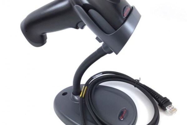
share
- Дата публикации: 28.01.2019
- Ссылка на публикацию: скопировать
- Скачать: Скачать руководство сканера Honeywell 1450G (48.5KB)cloud_download
Руководство пользователя 2D сканера штрих кода Honeywell 1450G
Это может быть интересно
more_vert
155000Тг
star_borderstar_borderstar_borderstar_borderstar_border
подробнее
more_vert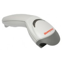
29700Тг
star_borderstar_borderstar_borderstar_borderstar_border
подробнее
more_vert
99000Тг
star_borderstar_borderstar_borderstar_borderstar_border
подробнее
Чековый принтер IKKM (USB+Ethernet)close
Чековый принтер IKKM (USB+Ethernet)
снабжен автообрезчиком гильотинного типа, имеет интерфейс USB, высокую скорость печати и низкий уровень шума при работе. Имеет компактный размер и можно ..
more_vert
121000Тг
star_borderstar_borderstar_borderstar_borderstar_border
подробнее
more_vert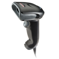
38500Тг
star_borderstar_borderstar_borderstar_borderstar_border
подробнее
more_vert
181500Тг
star_borderstar_borderstar_borderstar_borderstar_border
подробнее
Honeywell является одной из крупнейших организаций, создающей оборудование для автоматизации промышленных отраслей. Большой популярностью пользуются выпущенные данной компанией технические средства, предназначенные для автоматической идентификации. Среди производимых Honeywell продуктов имеется широкий выбор считывающих устройств, разработанных для различных бизнес ниш. В данной статье мы подробно рассмотрим одно из них, универсальное устройство для распознавания кодированных меток (штрих-кодов) Honeywell Voyager 1450g.
Инструкция к Honeywell Voyager 1450g
Honeywell Voyager 1450g — недорогое устройство класса защиты IP40, обладающее фотосканерным способом считывания штриховых обозначений. Представляет собой ручной аппарат, распознающий 2D штрих-коды и осуществляющий до 10 сканирований в секунду на расстоянии до 55 сантиметров. Сканер может функционировать в температурном диапазоне от 0С° до +40С°.
Достоинства Honeywell Voyager 1450g:
-
Несколько интерфейсов для присоединения к основному оборудованию (RS232, USB) и возможность работы в разрыв клавиатуры;
-
Удобство эксплуатации, благодаря возможности ручного и стационарного (при использовании подставки, входящей в комплект) использования;
-
Два режима распознавания: при помощи нажатия курка и при поднесении штрих-кода к датчику;
-
Способность интеграции с KKM Эвотор и другими KKT;
-
Распознавание данных, вне зависимости от угла наклона на дистанции до 55 сантиметров;
-
Подтверждение действий при помощи света и звука.
Благодаря фотосканерному принципу работы, устройство может распознавать даже мятые и сильно повреждённые штрих-коды, метки с низким разрешением, а также обозначения с экранов гаджетов.
Сферы использования
Благодаря высокой скорости обработки информации и удобству использования, Honeywell 1450g может применяться в любых организациях, осуществляющих торговую деятельность, на розничных и оптовых складах. Будет хорошим решением при оснащении небольших точек розничных продаж со средней проходимостью не более 250 клиентов в течение смены. Также имеющееся количество функциональных возможностей подойдёт для оптимизации:
-
аптечных пунктов;
-
фирменных бутиков;
-
отделов, реализующих косметические средства по уходу и парфюмерию;
-
небольших пунктов розничных продаж, киосков и роспечатей;
-
кофеен и небольших заведений, предоставляющих услуги общественного питания.
Для использования подобного оборудования не нужно специализированных навыков или дополнительного обучения. Необходимо лишь изучить руководство по использованию или инструкцию, поставляемые в комплекте с устройством. Данный сканер отвечает всем предписаниям ФСРАР и может распознавать обозначения PDF417, присутствующие на бутылках с алкогольной продукцией. Интегрируется с такими системами, как «Меркурий» и ЕГАИС.
Хорошо подходит для реализации изделий из меха, а также остальных маркированных изделий. При этом Honeywell 1450g обладает бюджетной стоимостью, цена на этот сканер варьируется от 4500 до 7000 рублей, что позволяет сэкономить финансы во время перехода на новую систему.

Инструкция по установке Honeywell Voyager 1450g
Данный сканер можно подсоединить к любому кассовому оборудованию или компьютеру. После чего следует указать режим эксплуатации, который напрямую зависит от способа подсоединения.
Способы подсоединения устройства:
-
В разрыв соединения – данный способ подключения предполагает освободить интерфейсы для подключения другого периферийного оборудования, также после распознавания обозначения, расшифрованные данные переносятся в поле курсора, что позволяет с легкостью вносить товарные позиции в программу учета товара. Провод подсоединяемого оборудования с интерфейсом RS/2 оканчивается разветвлением: один разъём для клавиатуры, а другой для компьютера, а сам сканер подключается к сети через выносной аккумулятор.
-
СОМ-порт (RS232) – популярный способ подсоединения к POS-системам. Чтобы его использовать, необходима установка соответствующего ПО. Обычно не подходит для подсоединения к новейшим компьютерам или планшетам, т.к. у них отсутствует подобный интерфейс.
-
RS-485 подключение предназначено для взаимодействия с POS-оборудованием IBM.
-
USB – при подобном подключении нет необходимости в использовании дополнительной аккумуляторной батареи, подходит для интеграции со всеми существующими контрольно-кассовыми системами. Информация, полученная после распознавания штрих-кода, появляется на месте курсора.
В руководстве по использованию Honeywell Voyager 1450g обозначено, что данное устройство при работе использует новейшую технологию Power Link, что позволяет облегчить процедуру замены проводов и отработавших аккумуляторных батарей. Их можно легко заменить, не используя при этом специальных приспособлений.
В комплекте со сканером предоставляется трехметровый кабель.
Каким способом подсоединения устройства воспользоваться
Для подключения устройства к POS-моноблоку, лучше всего использовать USB-разъем. Для POS-систем лучше всего воспользоваться RS232, это позволит обеспечить стабильную и бесперебойную работу устройства.
Также способ подключения должен соответствовать установленному ПО. Так, когда на компьютере инсталлирована 1С, то в качестве соединения лучше выбрать RS232, т.к. он интегрируется с бесплатным приложением, предусмотренным 1С. Для осуществления набора штрих-кодов в текстовые документы или для заполнения товарной номенклатуры (каталог имеющейся продукции) лучшим решением будет подключение сканера в разрыв клавиатуры.
Инструкция по использованию Honeywell Voyager 1450g
Honeywell Voyager 1450g – это сканер, распознающий информацию при помощи фотодатчиков и способный распознавать данные в разных плоскостях. Для облегчения процедуры распознавания при стационарном использовании, установите сканер в подставке так, чтобы луч находился по центру подносимых штрих-кодов. При ручном использовании наведите датчики сканера на изображение, нажмите на курок и расположите луч по центру штрих-кода. Чем дальше сканер от штрих-кода, тем больше луч, и наоборот.
Для более быстрого распознавания обозначений, нужно располагать устройство как можно дальше от крупных изображений и поближе к небольшим. Если поверхность, с которой осуществляется распознавание, глянцевая или блестящая, то лучше располагать луч наклонно.
Обратите внимание на то, что перед тем, как начать процедуру подключения оборудования, необходимо отключить основное устройство от сети питания.

Инструкция по настройке сканирующего оборудования Honeywell Voyager 1450g
Для программирования устройства необходимо использовать специализированные штрих-коды, которые находятся в руководстве по эксплуатации устройства, идущему в комплекте с оборудованием, а также их можно найти на официальном сайте изготовителя.
Для того, чтобы настроить оборудование, необходимо обнулить заводские настройки и выставить требуемые параметры. Чтобы вернуть устройство в изначальное состояние, нужно считать метку для сброса настроек и установить заводские настройки, считав штрих-код, подписанный [Стандартные настройки по умолчанию для устройства].
Следующие действия зависят от активированного режима функционирования сканера. Если соединение с основным устройством произведено через интерфейс USB, то активируйте на сканере режим HID POS, считав соответствующее штрих-обозначение.
СОМ-режим тоже активируется считыванием нужной метки.
Вот перечень функций, которые можно активировать считыванием специализированных штрих-кодов:
-
активация разделительной полосы;
-
допуск к диспетчеру устройств (для осуществления проверки корректности подсоединения устройства);
-
добавление суффикса (берёт на себя задачу клавиши [Enter]) и префикса (берёт на себя задачу клавиши [F1, автоматически открывая окно ввода);
-
программирование функции [Control], позволяющей отправлять в программу непечатные обозначения;
-
активация режима подключения интерфейса RS-485, необходимого для взаимодействия с POS-оборудованием IBM;
-
активация режима взаимодействия оборудования совместно с программным обеспечением Data Matrix, для реализации маркированной продукции;
-
возможность включения режима непрерывной работы (подобная функция будет удобна для осуществления распознавания меток с чеков предзаказа, например, в заведениях, реализующих еду на вынос). Изначально оборудование настроено на осуществление работы в ручном режиме (сканирование происходит только после нажатия курка). Для активации презентационного режима, необходимо считать соответствующую метку.
Это стандартные функции, программируемые при помощи распознавания специального штрих-обозначения. Настроить оборудование можно, считав обозначения из бумажного руководства по использованию устройства, либо прямо с экрана компьютера, открыв их на сайте изготовителя.
Ошибки, совершаемые во время сканирования
Изначально Honeywell Voyager 1450g запрограммирован на распознавание восьмизначного EAN. Когда сканируется штрих-код с обозначением из 7 цифр, устройство в автоматическом режиме проставляет ещё один 0. Так как в программе основного устройства товар заведён как семизначное обозначение, появляется системное сообщение [Позиция отсутствует в товарной базе]. Для того, чтобы реализовать подобный товар, надо либо ввести цифровое обозначение штрих-кода вручную. Либо перевести его в соответствующий режим, путем перенастройки.
В момент распознавания акцизных марок, вместо стандартного обозначения иногда появляется 136-***. Подобная ошибка может происходить, если выставлена неверная настройка. Например, активирован режим сканирования DataMatrix. Для его отключения необходимо отсканировать соответствующую метку.
Инструкция по установке драйверов на Honeywell Voyager 1450g
Если по какой-то причине нет возможности воспользоваться драйверами, предоставляемыми в комплекте с оборудованием, то их можно загрузить с официального сайта производителя. При выборе программного обеспечения следует отталкиваться от установленной ОС и предполагаемого режима работы.
EZConfig for Scanning — бесплатная программа, позволяющая ускорить и облегчить процесс использования сканирующего оборудования. После того, как она будет инсталлирована на компьютер, префиксы и суффиксы будут проставлены в автоматическом режиме (дополнительной настройки по штрих-кодам не требуется). Данная утилита автоматически распознает подключенное сканирующее устройство, вне зависимости от типа подсоединения оборудования. Также, благодаря данной программе, появляется возможность быстрой смены настроек или перепрошивки оборудования в соответствии с потребностями.
Часто небольшие магазины используют вместо кассового оборудования обычные компьютеры, на которые предварительно инсталлировано соответствующие программное обеспечение и установлен фискальный регистратор. Если оборудование подсоединено через СОМ-порт, то программа просто подбирается в соответствии с установленной на компьютере операционной системой.
Почти все новые компьютеры не оснащены интерфейсом RS232, и подключать сканер приходиться через USB-порт. У многих пользователей на этом этапе появляются такие проблемы:
-
сканер не функционирует;
-
отсканированные изображения не переносятся в текстовый документ;
-
1С не может опознать оборудование и другие.
Для исправления подобных ошибок необходимо:
-
скачать на сайте производителя утилиту USB Serial Driver (Virtual COM Port driver);
-
открыть [Диспетчер устройств] и убедиться в том, что там отображается новый интерфейс;
-
перезагрузить персональный компьютер, после чего заново проверить работоспособность сканирующего оборудования.
Настройка Honeywell Voyager 1450g в программе EZConfig for Scanning
Загрузите программу EZConfig for Scanning с официального сайта производителя во вкладке Software, после чего при помощи установочного файла инсталлируйте её на компьютер. Для дальнейшей настройки сканера необходимо:
-
подсоединить сканирующее оборудование к выключенному компьютеру, после чего включить его;
-
открыть EZConfig for Scanning и активировать режим [автонастройки];
-
открыть раздел [Setting] и перейти во вкладку [Interfaces]→[ Keyboard Wedge];
-
активировать режим передачи управляющих символов [ASCII] в положение [CTRL + X ModeON];
-
открыть страницу [DATA FORMATTING] и перейти в раздел [Prefix/Suffix].
-
в появившейся форме активировать префикс и суффикс, нажав кнопку [ON];
-
в строке префикс указать обозначение US, а в графе суффикс CR;
-
подтвердите изменения, нажав [Save To Device].
Настройка Honeywell Voyager 1450g в программе в 1С
-
Запустите 1С и перейдите в раздел [Торговое оборудование], после чего откройте вкладку [Подключение и настройка], наведите на строчку [Сканеры] и нажмите [Добавить];
-
В открывшемся меню внесите параметры сканирующего устройства (наименование и номер устройства);
-
Сформируйте группу лиц, которым будет открыт доступ к использованию оборудования и подтвердите действие нажатием кнопки [ОК];
-
Нажмите на [Проверить подключенное оборудование] и дождитесь подтверждение того, что оборудование было добавлено;
-
Откройте вкладку [Параметры] и перейдите в [драйвер сканера], после чего запустите поиск оборудования.
-
Убедитесь в том, что устройство было успешно добавлено.
Чтобы убедиться в том, что добавленное устройство корректно функционирует, необходимо создать документ [Поступление товаров и услуг] и заполнить строки при помощи установленного сканера. Для этого наведите курсор на свободную строку и отсканируйте товарный штрих-код, данные о товаре должны заполниться в автоматическом режиме. В случае, если товарная позиция еще не заведена в программу, появится диалоговое окно с запросом добавления новой товарной позиции.
Наш каталог продукции
У нас Вы найдете широкий ассортимент товаров в сегментах кассового, торгового, весового, банковского и офисного оборудования

