-
Contents
-
Table of Contents
-
Bookmarks
Quick Links
Sliding gate operator
FA00945-EN
BX series
BX704AGS / 708AGS
BX708RGS
EN English
INSTALLATION MANUAL
Related Manuals for CAME BX708AGS
Summary of Contents for CAME BX708AGS
-
Page 1
Sliding gate operator FA00945-EN BX series BX704AGS / 708AGS BX708RGS EN English INSTALLATION MANUAL… -
Page 3
Before continuing, also read the general precautions for users. This product must only be used for its specifi cally intended purpose. any other use may be hazardous. Came S.p.A. is not liable for any damage caused by improper, wrongful and unreasonable use. • This manual’s product is defi ned by machinery directive 2006/42/CE as «partly-completed machinery». -
Page 4: Intended Use
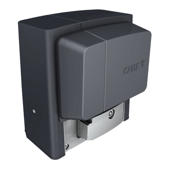
BX704AGS Operator (tested in compliance with EUROPEAN STANDARDS on shock forces) featuring a control board, movement control and obstruction detecting device plus mechanical limit-switches for sliding gates weighing up to 400 kg. BX708AGS Operator featuring a control board, movement control and obstruction detecting device plus mechanical limit-switches for sliding gates weighing up to 800 kg.
-
Page 5: Duty Cycles
DUTY CYCLES BX704AGS / BX708AGS Datum BX7080RGS Cycles/hour (no.) Consecutive cycles (no.) The cycles calculation refers to a gate that has a standard reference length (see the intended use), that are professionally installed, free of any mechanical issues and/or accidental friction points, and measured at 20° C, as stated in EN Standard 60335-2-103.
-
Page 6: Description Of Parts
DESCRIPTION OF PARTS 1. Cover 8. ZBX7N control board 2. Front cover 9. Limit-switch fins 3. Gear motor 10. Transformer 4. Condenser 11. Release hatch 5. Mechanical limit switch 12. Fastening hardware 6. Anchoring plate 13. Mounting brace for housing accessories (optional) 7.
-
Page 7: Preliminary Checks
GENERAL INSTALLATION INDICATIONS ⚠ Only skilled, qualified staff must install this product. PRELIMINARY CHECKS ⚠ Before beginning the installation, do the following: • check that the upper slide-guides are friction-free; • check that the gate is stable and that the casters are in good working order and lubricated; •…
-
Page 8
FITTING THE ANCHORING PLATE Set up a foundation frame that is larger than the anchoring plate and sink it into the dug hole. The foundation frame must jut out by 50 mm above ground level. Fit an iron cage into the foundation frame to reinforce the concrete. Fit the bolts into the anchoring plate and tighten them using the nuts. -
Page 9
Remove the foundation frame and fill the hole with earth around the concrete block. Remove the nuts from the bolts. Fit the electric cables into the tubes so that they come out about 600 mm. -
Page 10
SETTING UP THE OPERATOR Removethe front cover and the operator casing. Place the operator on top of the anchoring plate. Caution! The electric cables must pass under the gearmotor casing and must not touch any parts that may overheat during use, such as the motor or the transformer, and so on). -
Page 11
FASTENING THE RACK If the rack is already set up, the next step should be to adjust the rack-and-pinion coupling distance, otherwise, fasten it: — release the operator; — rest the rack above the operator pinion; — weld or fasten the rack to the gate along its entire length. To assemble the rack modules, use an extra piece and rest it under the joint, then fasten it using two clamps. -
Page 12
FASTENING THE OPERATOR Once the adjustments are complete, fasten the operator to the plate using the supplied hardware. ESTABLISHING THE LIMIT-SWITCH POINTS For opening: — open the gate; — fi t the opening limit-switch tab onto the rack until the micro switch activates (spring) and fasten it using the grub screws. Spring ~ 20 mm For closing:… -
Page 13: Control Board
CONTROL BOARD ⚠ Caution! Before doing any work on the control board, cut off the mains power supply, and disconnect any batteries. The functions available on the input and output contacts, the time adjustments and user management are all set and viewable on the segmented graphic display.
-
Page 14: Electrical Connections
ELECTRICAL CONNECTIONS ⚠ Connect all wires and cables in compliance with the law. Before connecting all the wires, set up the cables by using cable glands on the control board brace, as shown in the figure. ⚠ The electrical cables must not touch any heated parts such as the motor, transformer, and so on. Control-board brace cable glands FACTORY WIRING 120/230V (AC) gear motor with…
-
Page 15: Power Supply
POWER SUPPLY To change the motor torque, plug the faston terminal as shown into one 120 / 230 V AC 50/60 Hz of the four positions; from 1 (min.) to 4 (max.). White Blue Black Purple Orange Accessories power supply output 24 V AC, max 20 W.
-
Page 16: Control Devices
CONTROL DEVICES WARNING! For the system to work properly, before fitting any snap-in card (e.g. the AF R800), you MUST CUT OFF THE MAIN POWER SUPPLY and remove any batteries. STOP button (NC contact). For stopping the gate while excluding automatic closing.
-
Page 17: Safety Devices
SAFETY DEVICES Photocells Configure contact CX or CY (NC), safety input for photocells. See functions F2 (CXinput), or F3 (CY input) in: — C1 reopening during closing. When the gate is closing, opening the contact triggers the inversion of movement until the gate is fully open again; — C2 closing during opening.
-
Page 18
RIOCN8WS RIOED8WS RIOPH8WS RIOLX8WS PAIRED OPERATION OR CRP (CAME REMOTE PROTOCOL) Serial RS485 connection via CRP (Came Remote Protocol) or UTP CAT 5 for paired operation (see chapter called PAIRED OPERATION). A B GND Fit the RSE card. -
Page 19: Description Of The Commands
PROGRAMMING DESCRIPTION OF THE COMMANDS The ENTER key is for: — entering menus; — confirming or memorizing set values. The < > keys are for: Display — moving from one item to another; — increasing or decreasing a value; — opening and closing the gate (only when testing). The ESC button is for: — exiting menus;…
-
Page 20
After every opening or closing command, the board will check whether the photocells are working properly. The safety test is always active for wireless devices. Safety test This function only appears if the photocells have been enabled. OFF= Deactivated (default) / 1=CX / 2=CY / 4=CX+CY The gate opens and closes by keeping the button pressed. -
Page 21
Peripheral number 1 —-> 255 For setting the communication speed used in the CRP (Came Remote Protocol) connection system. COM speed 0 = 1200 Baud / 1 = 2400 Baud / 2 = 4800 Baud / 3 = 9600 Baud / 4 = 14400 Baud / 5 = 19200 Baud… -
Page 22
1 = all (default) / 2 = Rolling Code / 3 = TWIN Select the type of operator used on the system. Motor type 1 = BX704AGS / 2 = BX708AGS Automatic calibration of the gate-leaf swing (see the CALIBRATING SWING paragraph). This function only appears if function F11 is activated. -
Page 23: Travel Calibration
TRAVEL CALIBRATION ⚠ Before calibrating the gate travel, position the gate half-way, check that the maneuvering area is clear of any obstruction and check that there are mechanical opening and closing stops. ⚠ The mechanical gate-stops are obligatory. Important! During calibration, all safety devices will be disabled. Select [A 3] window.
-
Page 24
LIST OF REGISTERED USERS… -
Page 25
DELETING SINGLE USERS ❶ Select U 2. Press ENTER to confirm. ❷ Use the arrow keys select the number of the user you wish to delete. Press ENTER to confirm… ❸ … CLr will appear on the screen to confirm deletion. -
Page 26: Error Messages
SAVING AND UPLOADING ALL DATA (USERS AND CONFIGURATION) WITH THE MEMORY ROLL Procedure for memorizing all of the system’s user and configuration data by using the Memory Roll, so they can be used with another control board, even on another system. Caution! Fitting and extracting the Memory Roll must be done with the mains power disconnected.
-
Page 27: Dismantling And Disposal
SLAVE DISMANTLING AND DISPOSAL ☞ CAME CANCELLI AUTOMATICI S.p.A. applies a certified Environmental Management System at its premises, which is compliant with the UNI EN ISO 14001 standard to ensure the environment is safeguarded. Please continue safeguarding the environment. At CAME we consider it one of the fundamentals of our operating and market strategies. Simply…
-
Page 28
The contents of this manual may change, at any time, and without notice. CAME S.p.A. Via Martiri Della Libertà, 15 31030 Dosson di Casier — Treviso — Italy tel. (+39) 0422 4940 — fax. (+39) 0422 4941…

ИНСТРУКЦИИ ПО МОНТАЖУ И ЭКСПЛУАТАЦИИ
 |
Распашные ворота ИНСТРУКЦИИ ПО МОНТАЖУ И ЭКСПЛУАТАЦИИ … Инструкция по эксплуатации автоматики распашных ворот (гарантийный талон), Привод ATI (А3000а-А5000а-A3024-A5024), Привод ATI (A3024N-A5024N), и другая информация. |
 |
Гаражные ворота ИНСТРУКЦИИ ПО МОНТАЖУ И ЭКСПЛУАТАЦИИ… Инструкция по эксплуатации автоматики гаражных ворот (гарантийный талон), Привод VER 700E (new), Привод VER 900E (new), и другая информация. |
 |
Промышленные ворота ИНСТРУКЦИИ ПО МОНТАЖУ И ЭКСПЛУАТАЦИИ… Инструкция по эксплуатации автоматики промышленных ворот (гарантийный талон), C010, C009, и другая информация. |
 |
Автоматические шлагбаумы ИНСТРУКЦИИ ПО МОНТАЖУ И ЭКСПЛУАТАЦИИ… Подразделы: Принадлежности для G4040 /G2080 (9), Принадлежности для G2500/G4000/G6000/G12000 (6). |
 |
Парковки и цепные барьеры ИНСТРУКЦИИ ПО МОНТАЖУ И ЭКСПЛУАТАЦИИ… Инструкция по эксплуатации автоматических барьеров и парковок (гарантийный талон), Парковка UNIPARK, Цепной барьер САТ-Х, и другая информация. |
 |
Автоматика для дверей ИНСТРУКЦИИ ПО МОНТАЖУ И ЭКСПЛУАТАЦИИ… Радар MR8107, Радар MR8106, Привод SIPARIO, и другая информация. |
 |
Блоки управления ИНСТРУКЦИИ ПО МОНТАЖУ И НАСТРОЙКЕ… Подразделы: Блоки управления для двигателей 220 В (16), Блоки управления для двигателей 380 В, Блоки управления для двигателей 24 В (16), Резервное питание для двигателей 24 В (5). |
 |
Радиоуправление ИНСТРУКЦИИ ПО МОНТАЖУ И ПРОГРАММИРОВАНИЮ … Совместимость пультов CAME с приёмниками и блоками управления, Пульт TОР-432EE, Пульт TОР-434EE, и другая информация. |
 |
Устройства управления ИНСТРУКЦИИ ПО МОНТАЖУ… TSP01, SMA (с дисплеем NEW), SMA, и другая информация. |
 |
Устройства безопасности ИНСТРУКЦИИ ПО МОНТАЖУ… Лампа светодиодная Dadoo 001DD-1KA, Лампа KIARO N/KIARO 24N, Лампа со счётчиком KIARO IN, и другая информация. |
 |
Турникеты ИНСТРУКЦИИ ПО МОНТАЖУ… WING, SALOON, GUARDIAN, и другая информация. |
 |
Контроль доступа ИНСТРУКЦИИ ПО МОНТАЖУ… |
 |
Оконная автоматика MOWIN Инструкции по монтажу автоматики для окон Comunello MOWIN… Инструкция на цепной привод LIWIN, Инструкция на реечный привод AIRWIN, Инструкция на штоковый привод RAYWIN, и другая информация. |
-
Contents
-
Table of Contents
-
Bookmarks
Quick Links
Sliding gate operator
FA00945-EN
BX series
BX704AGS / 708AGS
BX708RGS
EN English
INSTALLATION MANUAL
Related Manuals for CAME BX708AGS
Summary of Contents for CAME BX708AGS
-
Page 1
Sliding gate operator FA00945-EN BX series BX704AGS / 708AGS BX708RGS EN English INSTALLATION MANUAL… -
Page 3
Before continuing, also read the general precautions for users. This product must only be used for its specifi cally intended purpose. any other use may be hazardous. Came S.p.A. is not liable for any damage caused by improper, wrongful and unreasonable use. • This manual’s product is defi ned by machinery directive 2006/42/CE as «partly-completed machinery». -
Page 4: Intended Use
BX704AGS Operator (tested in compliance with EUROPEAN STANDARDS on shock forces) featuring a control board, movement control and obstruction detecting device plus mechanical limit-switches for sliding gates weighing up to 400 kg. BX708AGS Operator featuring a control board, movement control and obstruction detecting device plus mechanical limit-switches for sliding gates weighing up to 800 kg.
-
Page 5: Duty Cycles
DUTY CYCLES BX704AGS / BX708AGS Datum BX7080RGS Cycles/hour (no.) Consecutive cycles (no.) The cycles calculation refers to a gate that has a standard reference length (see the intended use), that are professionally installed, free of any mechanical issues and/or accidental friction points, and measured at 20° C, as stated in EN Standard 60335-2-103.
-
Page 6: Description Of Parts
DESCRIPTION OF PARTS 1. Cover 8. ZBX7N control board 2. Front cover 9. Limit-switch fins 3. Gear motor 10. Transformer 4. Condenser 11. Release hatch 5. Mechanical limit switch 12. Fastening hardware 6. Anchoring plate 13. Mounting brace for housing accessories (optional) 7.
-
Page 7: Preliminary Checks
GENERAL INSTALLATION INDICATIONS ⚠ Only skilled, qualified staff must install this product. PRELIMINARY CHECKS ⚠ Before beginning the installation, do the following: • check that the upper slide-guides are friction-free; • check that the gate is stable and that the casters are in good working order and lubricated; •…
-
Page 8
FITTING THE ANCHORING PLATE Set up a foundation frame that is larger than the anchoring plate and sink it into the dug hole. The foundation frame must jut out by 50 mm above ground level. Fit an iron cage into the foundation frame to reinforce the concrete. Fit the bolts into the anchoring plate and tighten them using the nuts. -
Page 9
Remove the foundation frame and fill the hole with earth around the concrete block. Remove the nuts from the bolts. Fit the electric cables into the tubes so that they come out about 600 mm. -
Page 10
SETTING UP THE OPERATOR Removethe front cover and the operator casing. Place the operator on top of the anchoring plate. Caution! The electric cables must pass under the gearmotor casing and must not touch any parts that may overheat during use, such as the motor or the transformer, and so on). -
Page 11
FASTENING THE RACK If the rack is already set up, the next step should be to adjust the rack-and-pinion coupling distance, otherwise, fasten it: — release the operator; — rest the rack above the operator pinion; — weld or fasten the rack to the gate along its entire length. To assemble the rack modules, use an extra piece and rest it under the joint, then fasten it using two clamps. -
Page 12
FASTENING THE OPERATOR Once the adjustments are complete, fasten the operator to the plate using the supplied hardware. ESTABLISHING THE LIMIT-SWITCH POINTS For opening: — open the gate; — fi t the opening limit-switch tab onto the rack until the micro switch activates (spring) and fasten it using the grub screws. Spring ~ 20 mm For closing:… -
Page 13: Control Board
CONTROL BOARD ⚠ Caution! Before doing any work on the control board, cut off the mains power supply, and disconnect any batteries. The functions available on the input and output contacts, the time adjustments and user management are all set and viewable on the segmented graphic display.
-
Page 14: Electrical Connections
ELECTRICAL CONNECTIONS ⚠ Connect all wires and cables in compliance with the law. Before connecting all the wires, set up the cables by using cable glands on the control board brace, as shown in the figure. ⚠ The electrical cables must not touch any heated parts such as the motor, transformer, and so on. Control-board brace cable glands FACTORY WIRING 120/230V (AC) gear motor with…
-
Page 15: Power Supply
POWER SUPPLY To change the motor torque, plug the faston terminal as shown into one 120 / 230 V AC 50/60 Hz of the four positions; from 1 (min.) to 4 (max.). White Blue Black Purple Orange Accessories power supply output 24 V AC, max 20 W.
-
Page 16: Control Devices
CONTROL DEVICES WARNING! For the system to work properly, before fitting any snap-in card (e.g. the AF R800), you MUST CUT OFF THE MAIN POWER SUPPLY and remove any batteries. STOP button (NC contact). For stopping the gate while excluding automatic closing.
-
Page 17: Safety Devices
SAFETY DEVICES Photocells Configure contact CX or CY (NC), safety input for photocells. See functions F2 (CXinput), or F3 (CY input) in: — C1 reopening during closing. When the gate is closing, opening the contact triggers the inversion of movement until the gate is fully open again; — C2 closing during opening.
-
Page 18
RIOCN8WS RIOED8WS RIOPH8WS RIOLX8WS PAIRED OPERATION OR CRP (CAME REMOTE PROTOCOL) Serial RS485 connection via CRP (Came Remote Protocol) or UTP CAT 5 for paired operation (see chapter called PAIRED OPERATION). A B GND Fit the RSE card. -
Page 19: Description Of The Commands
PROGRAMMING DESCRIPTION OF THE COMMANDS The ENTER key is for: — entering menus; — confirming or memorizing set values. The < > keys are for: Display — moving from one item to another; — increasing or decreasing a value; — opening and closing the gate (only when testing). The ESC button is for: — exiting menus;…
-
Page 20
After every opening or closing command, the board will check whether the photocells are working properly. The safety test is always active for wireless devices. Safety test This function only appears if the photocells have been enabled. OFF= Deactivated (default) / 1=CX / 2=CY / 4=CX+CY The gate opens and closes by keeping the button pressed. -
Page 21
Peripheral number 1 —-> 255 For setting the communication speed used in the CRP (Came Remote Protocol) connection system. COM speed 0 = 1200 Baud / 1 = 2400 Baud / 2 = 4800 Baud / 3 = 9600 Baud / 4 = 14400 Baud / 5 = 19200 Baud… -
Page 22
1 = all (default) / 2 = Rolling Code / 3 = TWIN Select the type of operator used on the system. Motor type 1 = BX704AGS / 2 = BX708AGS Automatic calibration of the gate-leaf swing (see the CALIBRATING SWING paragraph). This function only appears if function F11 is activated. -
Page 23: Travel Calibration
TRAVEL CALIBRATION ⚠ Before calibrating the gate travel, position the gate half-way, check that the maneuvering area is clear of any obstruction and check that there are mechanical opening and closing stops. ⚠ The mechanical gate-stops are obligatory. Important! During calibration, all safety devices will be disabled. Select [A 3] window.
-
Page 24
LIST OF REGISTERED USERS… -
Page 25
DELETING SINGLE USERS ❶ Select U 2. Press ENTER to confirm. ❷ Use the arrow keys select the number of the user you wish to delete. Press ENTER to confirm… ❸ … CLr will appear on the screen to confirm deletion. -
Page 26: Error Messages
SAVING AND UPLOADING ALL DATA (USERS AND CONFIGURATION) WITH THE MEMORY ROLL Procedure for memorizing all of the system’s user and configuration data by using the Memory Roll, so they can be used with another control board, even on another system. Caution! Fitting and extracting the Memory Roll must be done with the mains power disconnected.
-
Page 27: Dismantling And Disposal
SLAVE DISMANTLING AND DISPOSAL ☞ CAME CANCELLI AUTOMATICI S.p.A. applies a certified Environmental Management System at its premises, which is compliant with the UNI EN ISO 14001 standard to ensure the environment is safeguarded. Please continue safeguarding the environment. At CAME we consider it one of the fundamentals of our operating and market strategies. Simply…
-
Page 28
The contents of this manual may change, at any time, and without notice. CAME S.p.A. Via Martiri Della Libertà, 15 31030 Dosson di Casier — Treviso — Italy tel. (+39) 0422 4940 — fax. (+39) 0422 4941…
ИНСТРУКЦИИ ПО МОНТАЖУ И ЭКСПЛУАТАЦИИ
|
|
Распашные ворота ИНСТРУКЦИИ ПО МОНТАЖУ И ЭКСПЛУАТАЦИИ … Инструкция по эксплуатации автоматики распашных ворот (гарантийный талон), Привод ATI (А3000а-А5000а-A3024-A5024), Привод ATI (A3024N-A5024N), и другая информация. |
|
|
Гаражные ворота ИНСТРУКЦИИ ПО МОНТАЖУ И ЭКСПЛУАТАЦИИ… Инструкция по эксплуатации автоматики гаражных ворот (гарантийный талон), Привод VER 700E (new), Привод VER 900E (new), и другая информация. |
|
|
Промышленные ворота ИНСТРУКЦИИ ПО МОНТАЖУ И ЭКСПЛУАТАЦИИ… Инструкция по эксплуатации автоматики промышленных ворот (гарантийный талон), C010, C009, и другая информация. |
|
|
Автоматические шлагбаумы ИНСТРУКЦИИ ПО МОНТАЖУ И ЭКСПЛУАТАЦИИ… Подразделы: Принадлежности для G4040 /G2080 (9), Принадлежности для G2500/G4000/G6000/G12000 (6). |
|
|
Парковки и цепные барьеры ИНСТРУКЦИИ ПО МОНТАЖУ И ЭКСПЛУАТАЦИИ… Инструкция по эксплуатации автоматических барьеров и парковок (гарантийный талон), Парковка UNIPARK, Цепной барьер САТ-Х, и другая информация. |
|
|
Автоматика для дверей ИНСТРУКЦИИ ПО МОНТАЖУ И ЭКСПЛУАТАЦИИ… Радар MR8107, Радар MR8106, Привод SIPARIO, и другая информация. |
|
|
Блоки управления ИНСТРУКЦИИ ПО МОНТАЖУ И НАСТРОЙКЕ… Подразделы: Блоки управления для двигателей 220 В (16), Блоки управления для двигателей 380 В, Блоки управления для двигателей 24 В (16), Резервное питание для двигателей 24 В (5). |
|
|
Радиоуправление ИНСТРУКЦИИ ПО МОНТАЖУ И ПРОГРАММИРОВАНИЮ … Совместимость пультов CAME с приёмниками и блоками управления, Пульт TОР-432EE, Пульт TОР-434EE, и другая информация. |
|
|
Устройства управления ИНСТРУКЦИИ ПО МОНТАЖУ… TSP01, SMA (с дисплеем NEW), SMA, и другая информация. |
|
|
Устройства безопасности ИНСТРУКЦИИ ПО МОНТАЖУ… Лампа светодиодная Dadoo 001DD-1KA, Лампа KIARO N/KIARO 24N, Лампа со счётчиком KIARO IN, и другая информация. |
|
|
Турникеты ИНСТРУКЦИИ ПО МОНТАЖУ… WING, SALOON, GUARDIAN, и другая информация. |
|
|
Контроль доступа ИНСТРУКЦИИ ПО МОНТАЖУ… |
|
|
Оконная автоматика MOWIN Инструкции по монтажу автоматики для окон Comunello MOWIN… Инструкция на цепной привод LIWIN, Инструкция на реечный привод AIRWIN, Инструкция на штоковый привод RAYWIN, и другая информация. |
Наши специалисты ответят на любой интересующий вопрос по услуге
Привода для откатных ворот серии BX изготавливаются компанией CAME CANCELLI AUTOMATICI S.p.A уже более 20 лет. За это время было произведено несколько поколений приводов работающих и по сей день. Привода отличаются между собой по внешнему виду, тяговым усилиям, различаются моторами, платами управления и функциями. Мы собрали в одном месте инструкции на привода CAME серии BX в одном месте.
Привода серии BX с моторами на 220B:
- Инструкция CAME BX-A — привод 220 В для откатных ворот до 400 кг, комплектовался платами управления ZBX6 или ZBX7, в зависимости от необходимых функций.
- Инструкция CAME BX-B — привод 220 В для откатных ворот до 800 кг, комплектовался платами управления ZBX6 или ZBX7, в зависимости от необходимых функций.
- Инструкция CAME BX-64-68 — привод 220 В для откатных ворот от 400 до 800 кг, комплектовался платами управления ZBX6.
- Инструкция CAME BX-10 — привод 220 В для откатных ворот до 800 кг, комплектовался платами управления ZBX10.
- Инструкция CAME BX-P — привод 220 В для откатных ворот до 800 кг, комплектовался платами управления ZBX8.
- Инструкция CAME BX-74-78 — привод 220 В для откатных ворот от 400 до 800 кг, комплектовался платами управления ZBX74-78.
- Инструкция CAME BX608AGS — привод 220 В для откатных ворот до 800 кг, комплектовался платами управления ZBX6N.
- Инструкция CAME BX704AGS — привод 220 В для откатных ворот до 400 кг, комплектовался платами управления ZBX7N.
- Инструкция CAME BX708AGS — привод 220 В для откатных ворот до 800 кг, комплектовался платами управления ZBX7N.
Привода серии BX с моторами на 24B:
- Инструкция CAME BX-243 — привод 24 В для откатных ворот до 300 кг, комплектовался платами управления ZN2.
- Инструкция CAME BX-324 — привод 24 В для откатных ворот до 300 кг, комплектовался платами управления ZN4.
- Инструкция CAME BX-246 — привод 24 В для откатных ворот до 600 кг, комплектовался платами управления ZD2.
- Инструкция CAME BXL04AGS — привод 24 В для откатных ворот до 400 кг, комплектовался платами управления ZN6.
- Инструкция CAME OPS001 (серия BROWN) — привод 24 В для откатных ворот до 400 кг, комплектовался платами управления ZN6
- Инструкция CAME BXV (SDN4, SDN6, SDN8, SDN10) — привода 24 В для откатных ворот от 400 до 1000 кг, комплектовался платами управления ZN7.

Инструкции по монтажу
- Распашные ворота
- Откатные ворота
- Гаражные ворота
- Промышленные ворота
- Автоматические шлагбаумы
- Парковки и цепные барьеры
- Автоматика для дверей
- Блоки управления
- Радиоуправление
- Устройства управления
- Устройства безопасности
- Турникеты
- Контроль доступа
- Оконная автоматика MOWIN
Главная
- КОМПЛЕКТЫ CAME
- Автоматика для распашных ворот
- Автоматика для ворот откатного типа
- Автоматика для гаражных ворот
- Автоматика для промышленных ворот
- Автоматические шлагбаумы
- Парковки и цепные барьеры
- Автоматические двери
- Турникеты
- Аксессуары управления
- Аксессуары безопасности
- Радиоуправление
- Системы управления паркингом PS ONE
- Запасные части САМЕ
- Комплектующие CAME для изготовления ворот
- Блокираторы URBACO
- Домофоны BPT
- Инструкции по монтажу
- Сертификаты САМЕ
- ИНТЕРНЕТ-МАГАЗИН
- —————————
- ЦЕНЫ
- Техподдержка
- Новости
- Видео
- Акции
- Доставка
- Статьи
- Сервисный центр
- Контакты

![]()
Распашные ворота
ИНСТРУКЦИИ ПО МОНТАЖУ И ЭКСПЛУАТАЦИИ …
Инструкция по эксплуатации автоматики распашных ворот (гарантийный талон), Привод ATI (А3000а-А5000а-A3024-A5024), Привод ATI (A3024N-A5024N), и другая информация.
Гаражные ворота
ИНСТРУКЦИИ ПО МОНТАЖУ И ЭКСПЛУАТАЦИИ…
Инструкция по эксплуатации автоматики гаражных ворот (гарантийный талон), Привод VER 700E (new), Привод VER 900E (new), и другая информация.
Промышленные ворота
ИНСТРУКЦИИ ПО МОНТАЖУ И ЭКСПЛУАТАЦИИ…
Инструкция по эксплуатации автоматики промышленных ворот (гарантийный талон), C010, C009, и другая информация.
Автоматические шлагбаумы
ИНСТРУКЦИИ ПО МОНТАЖУ И ЭКСПЛУАТАЦИИ…
Подразделы: Принадлежности для G4040 /G2080 (9), Принадлежности для G2500/G4000/G6000/G12000 (6).
Парковки и цепные барьеры
ИНСТРУКЦИИ ПО МОНТАЖУ И ЭКСПЛУАТАЦИИ…
Инструкция по эксплуатации автоматических барьеров и парковок (гарантийный талон), Парковка UNIPARK, Цепной барьер САТ-Х, и другая информация.
Автоматика для дверей
ИНСТРУКЦИИ ПО МОНТАЖУ И ЭКСПЛУАТАЦИИ…
Радар MR8107, Радар MR8106, Привод SIPARIO, и другая информация.
Блоки управления
ИНСТРУКЦИИ ПО МОНТАЖУ И НАСТРОЙКЕ…
Подразделы: Блоки управления для двигателей 220 В (16), Блоки управления для двигателей 380 В, Блоки управления для двигателей 24 В (16), Резервное питание для двигателей 24 В (5).
Радиоуправление
ИНСТРУКЦИИ ПО МОНТАЖУ И ПРОГРАММИРОВАНИЮ …
Совместимость пультов CAME с приёмниками и блоками управления, Пульт TОР-432EE, Пульт TОР-434EE, и другая информация.
Устройства управления
ИНСТРУКЦИИ ПО МОНТАЖУ…
TSP01, SMA (с дисплеем NEW), SMA, и другая информация.
Устройства безопасности
ИНСТРУКЦИИ ПО МОНТАЖУ…
Лампа светодиодная Dadoo 001DD-1KA, Лампа KIARO N/KIARO 24N, Лампа со счётчиком KIARO IN, и другая информация.
Турникеты
ИНСТРУКЦИИ ПО МОНТАЖУ…
WING, SALOON, GUARDIAN, и другая информация.
Контроль доступа
ИНСТРУКЦИИ ПО МОНТАЖУ…
Оконная автоматика MOWIN
Инструкции по монтажу автоматики для окон Comunello MOWIN…
Инструкция на цепной привод LIWIN, Инструкция на реечный привод AIRWIN, Инструкция на штоковый привод RAYWIN, и другая информация.
-
Contents
-
Table of Contents
-
Bookmarks
Quick Links
Sliding gate operator
FA00945-EN
BX series
BX704AGS / 708AGS
BX708RGS
EN English
INSTALLATION MANUAL
Related Manuals for CAME BX708AGS
Summary of Contents for CAME BX708AGS
-
Page 1
Sliding gate operator FA00945-EN BX series BX704AGS / 708AGS BX708RGS EN English INSTALLATION MANUAL… -
Page 3
Before continuing, also read the general precautions for users. This product must only be used for its specifi cally intended purpose. any other use may be hazardous. Came S.p.A. is not liable for any damage caused by improper, wrongful and unreasonable use. • This manual’s product is defi ned by machinery directive 2006/42/CE as «partly-completed machinery». -
Page 4: Intended Use
BX704AGS Operator (tested in compliance with EUROPEAN STANDARDS on shock forces) featuring a control board, movement control and obstruction detecting device plus mechanical limit-switches for sliding gates weighing up to 400 kg. BX708AGS Operator featuring a control board, movement control and obstruction detecting device plus mechanical limit-switches for sliding gates weighing up to 800 kg.
-
Page 5: Duty Cycles
DUTY CYCLES BX704AGS / BX708AGS Datum BX7080RGS Cycles/hour (no.) Consecutive cycles (no.) The cycles calculation refers to a gate that has a standard reference length (see the intended use), that are professionally installed, free of any mechanical issues and/or accidental friction points, and measured at 20° C, as stated in EN Standard 60335-2-103.
-
Page 6: Description Of Parts
DESCRIPTION OF PARTS 1. Cover 8. ZBX7N control board 2. Front cover 9. Limit-switch fins 3. Gear motor 10. Transformer 4. Condenser 11. Release hatch 5. Mechanical limit switch 12. Fastening hardware 6. Anchoring plate 13. Mounting brace for housing accessories (optional) 7.
-
Page 7: Preliminary Checks
GENERAL INSTALLATION INDICATIONS ⚠ Only skilled, qualified staff must install this product. PRELIMINARY CHECKS ⚠ Before beginning the installation, do the following: • check that the upper slide-guides are friction-free; • check that the gate is stable and that the casters are in good working order and lubricated; •…
-
Page 8
FITTING THE ANCHORING PLATE Set up a foundation frame that is larger than the anchoring plate and sink it into the dug hole. The foundation frame must jut out by 50 mm above ground level. Fit an iron cage into the foundation frame to reinforce the concrete. Fit the bolts into the anchoring plate and tighten them using the nuts. -
Page 9
Remove the foundation frame and fill the hole with earth around the concrete block. Remove the nuts from the bolts. Fit the electric cables into the tubes so that they come out about 600 mm. -
Page 10
SETTING UP THE OPERATOR Removethe front cover and the operator casing. Place the operator on top of the anchoring plate. Caution! The electric cables must pass under the gearmotor casing and must not touch any parts that may overheat during use, such as the motor or the transformer, and so on). -
Page 11
FASTENING THE RACK If the rack is already set up, the next step should be to adjust the rack-and-pinion coupling distance, otherwise, fasten it: — release the operator; — rest the rack above the operator pinion; — weld or fasten the rack to the gate along its entire length. To assemble the rack modules, use an extra piece and rest it under the joint, then fasten it using two clamps. -
Page 12
FASTENING THE OPERATOR Once the adjustments are complete, fasten the operator to the plate using the supplied hardware. ESTABLISHING THE LIMIT-SWITCH POINTS For opening: — open the gate; — fi t the opening limit-switch tab onto the rack until the micro switch activates (spring) and fasten it using the grub screws. Spring ~ 20 mm For closing:… -
Page 13: Control Board
CONTROL BOARD ⚠ Caution! Before doing any work on the control board, cut off the mains power supply, and disconnect any batteries. The functions available on the input and output contacts, the time adjustments and user management are all set and viewable on the segmented graphic display.
-
Page 14: Electrical Connections
ELECTRICAL CONNECTIONS ⚠ Connect all wires and cables in compliance with the law. Before connecting all the wires, set up the cables by using cable glands on the control board brace, as shown in the figure. ⚠ The electrical cables must not touch any heated parts such as the motor, transformer, and so on. Control-board brace cable glands FACTORY WIRING 120/230V (AC) gear motor with…
-
Page 15: Power Supply
POWER SUPPLY To change the motor torque, plug the faston terminal as shown into one 120 / 230 V AC 50/60 Hz of the four positions; from 1 (min.) to 4 (max.). White Blue Black Purple Orange Accessories power supply output 24 V AC, max 20 W.
-
Page 16: Control Devices
CONTROL DEVICES WARNING! For the system to work properly, before fitting any snap-in card (e.g. the AF R800), you MUST CUT OFF THE MAIN POWER SUPPLY and remove any batteries. STOP button (NC contact). For stopping the gate while excluding automatic closing.
-
Page 17: Safety Devices
SAFETY DEVICES Photocells Configure contact CX or CY (NC), safety input for photocells. See functions F2 (CXinput), or F3 (CY input) in: — C1 reopening during closing. When the gate is closing, opening the contact triggers the inversion of movement until the gate is fully open again; — C2 closing during opening.
-
Page 18
RIOCN8WS RIOED8WS RIOPH8WS RIOLX8WS PAIRED OPERATION OR CRP (CAME REMOTE PROTOCOL) Serial RS485 connection via CRP (Came Remote Protocol) or UTP CAT 5 for paired operation (see chapter called PAIRED OPERATION). A B GND Fit the RSE card. -
Page 19: Description Of The Commands
PROGRAMMING DESCRIPTION OF THE COMMANDS The ENTER key is for: — entering menus; — confirming or memorizing set values. The < > keys are for: Display — moving from one item to another; — increasing or decreasing a value; — opening and closing the gate (only when testing). The ESC button is for: — exiting menus;…
-
Page 20
After every opening or closing command, the board will check whether the photocells are working properly. The safety test is always active for wireless devices. Safety test This function only appears if the photocells have been enabled. OFF= Deactivated (default) / 1=CX / 2=CY / 4=CX+CY The gate opens and closes by keeping the button pressed. -
Page 21
Peripheral number 1 —-> 255 For setting the communication speed used in the CRP (Came Remote Protocol) connection system. COM speed 0 = 1200 Baud / 1 = 2400 Baud / 2 = 4800 Baud / 3 = 9600 Baud / 4 = 14400 Baud / 5 = 19200 Baud… -
Page 22
1 = all (default) / 2 = Rolling Code / 3 = TWIN Select the type of operator used on the system. Motor type 1 = BX704AGS / 2 = BX708AGS Automatic calibration of the gate-leaf swing (see the CALIBRATING SWING paragraph). This function only appears if function F11 is activated. -
Page 23: Travel Calibration
TRAVEL CALIBRATION ⚠ Before calibrating the gate travel, position the gate half-way, check that the maneuvering area is clear of any obstruction and check that there are mechanical opening and closing stops. ⚠ The mechanical gate-stops are obligatory. Important! During calibration, all safety devices will be disabled. Select [A 3] window.
-
Page 24
LIST OF REGISTERED USERS… -
Page 25
DELETING SINGLE USERS ❶ Select U 2. Press ENTER to confirm. ❷ Use the arrow keys select the number of the user you wish to delete. Press ENTER to confirm… ❸ … CLr will appear on the screen to confirm deletion. -
Page 26: Error Messages
SAVING AND UPLOADING ALL DATA (USERS AND CONFIGURATION) WITH THE MEMORY ROLL Procedure for memorizing all of the system’s user and configuration data by using the Memory Roll, so they can be used with another control board, even on another system. Caution! Fitting and extracting the Memory Roll must be done with the mains power disconnected.
-
Page 27: Dismantling And Disposal
SLAVE DISMANTLING AND DISPOSAL ☞ CAME CANCELLI AUTOMATICI S.p.A. applies a certified Environmental Management System at its premises, which is compliant with the UNI EN ISO 14001 standard to ensure the environment is safeguarded. Please continue safeguarding the environment. At CAME we consider it one of the fundamentals of our operating and market strategies. Simply…
-
Page 28
The contents of this manual may change, at any time, and without notice. CAME S.p.A. Via Martiri Della Libertà, 15 31030 Dosson di Casier — Treviso — Italy tel. (+39) 0422 4940 — fax. (+39) 0422 4941…
ИНСТРУКЦИИ ПО МОНТАЖУ И ЭКСПЛУАТАЦИИ
|
|
Распашные ворота ИНСТРУКЦИИ ПО МОНТАЖУ И ЭКСПЛУАТАЦИИ … Инструкция по эксплуатации автоматики распашных ворот (гарантийный талон), Привод ATI (А3000а-А5000а-A3024-A5024), Привод ATI (A3024N-A5024N), и другая информация. |
|
|
Гаражные ворота ИНСТРУКЦИИ ПО МОНТАЖУ И ЭКСПЛУАТАЦИИ… Инструкция по эксплуатации автоматики гаражных ворот (гарантийный талон), Привод VER 700E (new), Привод VER 900E (new), и другая информация. |
|
|
Промышленные ворота ИНСТРУКЦИИ ПО МОНТАЖУ И ЭКСПЛУАТАЦИИ… Инструкция по эксплуатации автоматики промышленных ворот (гарантийный талон), C010, C009, и другая информация. |
|
|
Автоматические шлагбаумы ИНСТРУКЦИИ ПО МОНТАЖУ И ЭКСПЛУАТАЦИИ… Подразделы: Принадлежности для G4040 /G2080 (9), Принадлежности для G2500/G4000/G6000/G12000 (6). |
|
|
Парковки и цепные барьеры ИНСТРУКЦИИ ПО МОНТАЖУ И ЭКСПЛУАТАЦИИ… Инструкция по эксплуатации автоматических барьеров и парковок (гарантийный талон), Парковка UNIPARK, Цепной барьер САТ-Х, и другая информация. |
|
|
Автоматика для дверей ИНСТРУКЦИИ ПО МОНТАЖУ И ЭКСПЛУАТАЦИИ… Радар MR8107, Радар MR8106, Привод SIPARIO, и другая информация. |
|
|
Блоки управления ИНСТРУКЦИИ ПО МОНТАЖУ И НАСТРОЙКЕ… Подразделы: Блоки управления для двигателей 220 В (16), Блоки управления для двигателей 380 В, Блоки управления для двигателей 24 В (16), Резервное питание для двигателей 24 В (5). |
|
|
Радиоуправление ИНСТРУКЦИИ ПО МОНТАЖУ И ПРОГРАММИРОВАНИЮ … Совместимость пультов CAME с приёмниками и блоками управления, Пульт TОР-432EE, Пульт TОР-434EE, и другая информация. |
|
|
Устройства управления ИНСТРУКЦИИ ПО МОНТАЖУ… TSP01, SMA (с дисплеем NEW), SMA, и другая информация. |
|
|
Устройства безопасности ИНСТРУКЦИИ ПО МОНТАЖУ… Лампа светодиодная Dadoo 001DD-1KA, Лампа KIARO N/KIARO 24N, Лампа со счётчиком KIARO IN, и другая информация. |
|
|
Турникеты ИНСТРУКЦИИ ПО МОНТАЖУ… WING, SALOON, GUARDIAN, и другая информация. |
|
|
Контроль доступа ИНСТРУКЦИИ ПО МОНТАЖУ… |
|
|
Оконная автоматика MOWIN Инструкции по монтажу автоматики для окон Comunello MOWIN… Инструкция на цепной привод LIWIN, Инструкция на реечный привод AIRWIN, Инструкция на штоковый привод RAYWIN, и другая информация. |
Наши специалисты ответят на любой интересующий вопрос по услуге
Привода для откатных ворот серии BX изготавливаются компанией CAME CANCELLI AUTOMATICI S.p.A уже более 20 лет. За это время было произведено несколько поколений приводов работающих и по сей день. Привода отличаются между собой по внешнему виду, тяговым усилиям, различаются моторами, платами управления и функциями. Мы собрали в одном месте инструкции на привода CAME серии BX в одном месте.
Привода серии BX с моторами на 220B:
- Инструкция CAME BX-A — привод 220 В для откатных ворот до 400 кг, комплектовался платами управления ZBX6 или ZBX7, в зависимости от необходимых функций.
- Инструкция CAME BX-B — привод 220 В для откатных ворот до 800 кг, комплектовался платами управления ZBX6 или ZBX7, в зависимости от необходимых функций.
- Инструкция CAME BX-64-68 — привод 220 В для откатных ворот от 400 до 800 кг, комплектовался платами управления ZBX6.
- Инструкция CAME BX-10 — привод 220 В для откатных ворот до 800 кг, комплектовался платами управления ZBX10.
- Инструкция CAME BX-P — привод 220 В для откатных ворот до 800 кг, комплектовался платами управления ZBX8.
- Инструкция CAME BX-74-78 — привод 220 В для откатных ворот от 400 до 800 кг, комплектовался платами управления ZBX74-78.
- Инструкция CAME BX608AGS — привод 220 В для откатных ворот до 800 кг, комплектовался платами управления ZBX6N.
- Инструкция CAME BX704AGS — привод 220 В для откатных ворот до 400 кг, комплектовался платами управления ZBX7N.
- Инструкция CAME BX708AGS — привод 220 В для откатных ворот до 800 кг, комплектовался платами управления ZBX7N.
Привода серии BX с моторами на 24B:
- Инструкция CAME BX-243 — привод 24 В для откатных ворот до 300 кг, комплектовался платами управления ZN2.
- Инструкция CAME BX-324 — привод 24 В для откатных ворот до 300 кг, комплектовался платами управления ZN4.
- Инструкция CAME BX-246 — привод 24 В для откатных ворот до 600 кг, комплектовался платами управления ZD2.
- Инструкция CAME BXL04AGS — привод 24 В для откатных ворот до 400 кг, комплектовался платами управления ZN6.
- Инструкция CAME OPS001 (серия BROWN) — привод 24 В для откатных ворот до 400 кг, комплектовался платами управления ZN6
- Инструкция CAME BXV (SDN4, SDN6, SDN8, SDN10) — привода 24 В для откатных ворот от 400 до 1000 кг, комплектовался платами управления ZN7.
Инструкции по монтажу
- Распашные ворота
- Откатные ворота
- Гаражные ворота
- Промышленные ворота
- Автоматические шлагбаумы
- Парковки и цепные барьеры
- Автоматика для дверей
- Блоки управления
- Радиоуправление
- Устройства управления
- Устройства безопасности
- Турникеты
- Контроль доступа
- Оконная автоматика MOWIN
Главная
- КОМПЛЕКТЫ CAME
- Автоматика для распашных ворот
- Автоматика для ворот откатного типа
- Автоматика для гаражных ворот
- Автоматика для промышленных ворот
- Автоматические шлагбаумы
- Парковки и цепные барьеры
- Автоматические двери
- Турникеты
- Аксессуары управления
- Аксессуары безопасности
- Радиоуправление
- Системы управления паркингом PS ONE
- Запасные части САМЕ
- Комплектующие CAME для изготовления ворот
- Блокираторы URBACO
- Домофоны BPT
- Инструкции по монтажу
- Сертификаты САМЕ
- ИНТЕРНЕТ-МАГАЗИН
- —————————
- ЦЕНЫ
- Техподдержка
- Новости
- Видео
- Акции
- Доставка
- Статьи
- Сервисный центр
- Контакты
![]()
Распашные ворота
ИНСТРУКЦИИ ПО МОНТАЖУ И ЭКСПЛУАТАЦИИ …
Инструкция по эксплуатации автоматики распашных ворот (гарантийный талон), Привод ATI (А3000а-А5000а-A3024-A5024), Привод ATI (A3024N-A5024N), и другая информация.
Гаражные ворота
ИНСТРУКЦИИ ПО МОНТАЖУ И ЭКСПЛУАТАЦИИ…
Инструкция по эксплуатации автоматики гаражных ворот (гарантийный талон), Привод VER 700E (new), Привод VER 900E (new), и другая информация.
Промышленные ворота
ИНСТРУКЦИИ ПО МОНТАЖУ И ЭКСПЛУАТАЦИИ…
Инструкция по эксплуатации автоматики промышленных ворот (гарантийный талон), C010, C009, и другая информация.
Автоматические шлагбаумы
ИНСТРУКЦИИ ПО МОНТАЖУ И ЭКСПЛУАТАЦИИ…
Подразделы: Принадлежности для G4040 /G2080 (9), Принадлежности для G2500/G4000/G6000/G12000 (6).
Парковки и цепные барьеры
ИНСТРУКЦИИ ПО МОНТАЖУ И ЭКСПЛУАТАЦИИ…
Инструкция по эксплуатации автоматических барьеров и парковок (гарантийный талон), Парковка UNIPARK, Цепной барьер САТ-Х, и другая информация.
Автоматика для дверей
ИНСТРУКЦИИ ПО МОНТАЖУ И ЭКСПЛУАТАЦИИ…
Радар MR8107, Радар MR8106, Привод SIPARIO, и другая информация.
Блоки управления
ИНСТРУКЦИИ ПО МОНТАЖУ И НАСТРОЙКЕ…
Подразделы: Блоки управления для двигателей 220 В (16), Блоки управления для двигателей 380 В, Блоки управления для двигателей 24 В (16), Резервное питание для двигателей 24 В (5).
Радиоуправление
ИНСТРУКЦИИ ПО МОНТАЖУ И ПРОГРАММИРОВАНИЮ …
Совместимость пультов CAME с приёмниками и блоками управления, Пульт TОР-432EE, Пульт TОР-434EE, и другая информация.
Устройства управления
ИНСТРУКЦИИ ПО МОНТАЖУ…
TSP01, SMA (с дисплеем NEW), SMA, и другая информация.
Устройства безопасности
ИНСТРУКЦИИ ПО МОНТАЖУ…
Лампа светодиодная Dadoo 001DD-1KA, Лампа KIARO N/KIARO 24N, Лампа со счётчиком KIARO IN, и другая информация.
Турникеты
ИНСТРУКЦИИ ПО МОНТАЖУ…
WING, SALOON, GUARDIAN, и другая информация.
Контроль доступа
ИНСТРУКЦИИ ПО МОНТАЖУ…
Оконная автоматика MOWIN
Инструкции по монтажу автоматики для окон Comunello MOWIN…
Инструкция на цепной привод LIWIN, Инструкция на реечный привод AIRWIN, Инструкция на штоковый привод RAYWIN, и другая информация.
Наши специалисты ответят на любой интересующий вопрос по услуге
Привода для откатных ворот серии BX изготавливаются компанией CAME CANCELLI AUTOMATICI S.p.A уже более 20 лет. За это время было произведено несколько поколений приводов работающих и по сей день. Привода отличаются между собой по внешнему виду, тяговым усилиям, различаются моторами, платами управления и функциями. Мы собрали в одном месте инструкции на привода CAME серии BX в одном месте.
Привода серии BX с моторами на 220B:
- Инструкция CAME BX-A — привод 220 В для откатных ворот до 400 кг, комплектовался платами управления ZBX6 или ZBX7, в зависимости от необходимых функций.
- Инструкция CAME BX-B — привод 220 В для откатных ворот до 800 кг, комплектовался платами управления ZBX6 или ZBX7, в зависимости от необходимых функций.
- Инструкция CAME BX-64-68 — привод 220 В для откатных ворот от 400 до 800 кг, комплектовался платами управления ZBX6.
- Инструкция CAME BX-10 — привод 220 В для откатных ворот до 800 кг, комплектовался платами управления ZBX10.
- Инструкция CAME BX-P — привод 220 В для откатных ворот до 800 кг, комплектовался платами управления ZBX8.
- Инструкция CAME BX-74-78 — привод 220 В для откатных ворот от 400 до 800 кг, комплектовался платами управления ZBX74-78.
- Инструкция CAME BX608AGS — привод 220 В для откатных ворот до 800 кг, комплектовался платами управления ZBX6N.
- Инструкция CAME BX704AGS — привод 220 В для откатных ворот до 400 кг, комплектовался платами управления ZBX7N.
- Инструкция CAME BX708AGS — привод 220 В для откатных ворот до 800 кг, комплектовался платами управления ZBX7N.
Привода серии BX с моторами на 24B:
- Инструкция CAME BX-243 — привод 24 В для откатных ворот до 300 кг, комплектовался платами управления ZN2.
- Инструкция CAME BX-324 — привод 24 В для откатных ворот до 300 кг, комплектовался платами управления ZN4.
- Инструкция CAME BX-246 — привод 24 В для откатных ворот до 600 кг, комплектовался платами управления ZD2.
- Инструкция CAME BXL04AGS — привод 24 В для откатных ворот до 400 кг, комплектовался платами управления ZN6.
- Инструкция CAME OPS001 (серия BROWN) — привод 24 В для откатных ворот до 400 кг, комплектовался платами управления ZN6
- Инструкция CAME BXV (SDN4, SDN6, SDN8, SDN10) — привода 24 В для откатных ворот от 400 до 1000 кг, комплектовался платами управления ZN7.
Инструкции по монтажу
- Распашные ворота
- Откатные ворота
- Гаражные ворота
- Промышленные ворота
- Автоматические шлагбаумы
- Парковки и цепные барьеры
- Автоматика для дверей
- Блоки управления
- Радиоуправление
- Устройства управления
- Устройства безопасности
- Турникеты
- Контроль доступа
- Оконная автоматика MOWIN
Главная
- КОМПЛЕКТЫ CAME
- Автоматика для распашных ворот
- Автоматика для ворот откатного типа
- Автоматика для гаражных ворот
- Автоматика для промышленных ворот
- Автоматические шлагбаумы
- Парковки и цепные барьеры
- Автоматические двери
- Турникеты
- Аксессуары управления
- Аксессуары безопасности
- Радиоуправление
- Системы управления паркингом PS ONE
- Запасные части САМЕ
- Комплектующие CAME для изготовления ворот
- Блокираторы URBACO
- Домофоны BPT
- Инструкции по монтажу
- Сертификаты САМЕ
- ИНТЕРНЕТ-МАГАЗИН
- —————————
- ЦЕНЫ
- Техподдержка
- Новости
- Видео
- Акции
- Доставка
- Статьи
- Сервисный центр
- Контакты
![]()
Привод BX608AGS
Привод BX704AGS_BX708AGS
Привод BKS12_18_22AGS
Привод BXV
Привод BKV
Привод BX 64 — BX 68
Привод BХ 74 — ВХ 78
Привод BХ А-В
Привод BХ 241
Привод BХ 243
Привод BХ 246
Привод BX-324
Привод BХ-Р
Привод BK (ВК1200-ВК1800-ВК2200)
Привод BK-1200P
Привод BK-221
Привод BY3500T
Оптический считыватель В4336
Инструкция по эксплуатации автоматики откатных ворот (гарантийный талон)
Соседние подразделы:
 |
Распашные ворота ИНСТРУКЦИИ ПО МОНТАЖУ И ЭКСПЛУАТАЦИИ … Инструкция по эксплуатации автоматики распашных ворот (гарантийный талон), Привод ATI (А3000а-А5000а-A3024-A5024), Привод ATI (A3024N-A5024N), и другая информация. |
 |
Гаражные ворота ИНСТРУКЦИИ ПО МОНТАЖУ И ЭКСПЛУАТАЦИИ… Инструкция по эксплуатации автоматики гаражных ворот (гарантийный талон), Привод VER 700E (new), Привод VER 900E (new), и другая информация. |
 |
Промышленные ворота ИНСТРУКЦИИ ПО МОНТАЖУ И ЭКСПЛУАТАЦИИ… Инструкция по эксплуатации автоматики промышленных ворот (гарантийный талон), C010, C009, и другая информация. |
 |
Автоматические шлагбаумы ИНСТРУКЦИИ ПО МОНТАЖУ И ЭКСПЛУАТАЦИИ… Подразделы: Принадлежности для G4040 /G2080 (9), Принадлежности для G2500/G4000/G6000/G12000 (6). |
 |
Парковки и цепные барьеры ИНСТРУКЦИИ ПО МОНТАЖУ И ЭКСПЛУАТАЦИИ… Инструкция по эксплуатации автоматических барьеров и парковок (гарантийный талон), Парковка UNIPARK, Цепной барьер САТ-Х, и другая информация. |
 |
Автоматика для дверей ИНСТРУКЦИИ ПО МОНТАЖУ И ЭКСПЛУАТАЦИИ… Радар MR8107, Радар MR8106, Привод SIPARIO, и другая информация. |
 |
Блоки управления ИНСТРУКЦИИ ПО МОНТАЖУ И НАСТРОЙКЕ… Подразделы: Блоки управления для двигателей 220 В (16), Блоки управления для двигателей 380 В, Блоки управления для двигателей 24 В (16), Резервное питание для двигателей 24 В (5). |
 |
Радиоуправление ИНСТРУКЦИИ ПО МОНТАЖУ И ПРОГРАММИРОВАНИЮ … Совместимость пультов CAME с приёмниками и блоками управления, Приёмник RE432M, Пульт TОР-432EE, и другая информация. |
 |
Устройства управления ИНСТРУКЦИИ ПО МОНТАЖУ… TSP01, SMA (с дисплеем NEW), SMA, и другая информация. |
 |
Устройства безопасности ИНСТРУКЦИИ ПО МОНТАЖУ… Лампа светодиодная Dadoo 001DD-1KA, Лампа KIARO N/KIARO 24N, Лампа со счётчиком KIARO IN, и другая информация. |
 |
Турникеты ИНСТРУКЦИИ ПО МОНТАЖУ… WING, SALOON, GUARDIAN, и другая информация. |
 |
Контроль доступа ИНСТРУКЦИИ ПО МОНТАЖУ… |
 |
Оконная автоматика MOWIN Инструкции по монтажу автоматики для окон Comunello MOWIN… Инструкция на цепной привод LIWIN, Инструкция на реечный привод AIRWIN, Инструкция на штоковый привод RAYWIN, и другая информация. |
Наши специалисты ответят на любой интересующий вопрос по услуге
Привода для откатных ворот серии BX изготавливаются компанией CAME CANCELLI AUTOMATICI S.p.A уже более 20 лет. За это время было произведено несколько поколений приводов работающих и по сей день. Привода отличаются между собой по внешнему виду, тяговым усилиям, различаются моторами, платами управления и функциями. Мы собрали в одном месте инструкции на привода CAME серии BX в одном месте.
Привода серии BX с моторами на 220B:
- Инструкция CAME BX-A — привод 220 В для откатных ворот до 400 кг, комплектовался платами управления ZBX6 или ZBX7, в зависимости от необходимых функций.
- Инструкция CAME BX-B — привод 220 В для откатных ворот до 800 кг, комплектовался платами управления ZBX6 или ZBX7, в зависимости от необходимых функций.
- Инструкция CAME BX-64-68 — привод 220 В для откатных ворот от 400 до 800 кг, комплектовался платами управления ZBX6.
- Инструкция CAME BX-10 — привод 220 В для откатных ворот до 800 кг, комплектовался платами управления ZBX10.
- Инструкция CAME BX-P — привод 220 В для откатных ворот до 800 кг, комплектовался платами управления ZBX8.
- Инструкция CAME BX-74-78 — привод 220 В для откатных ворот от 400 до 800 кг, комплектовался платами управления ZBX74-78.
- Инструкция CAME BX608AGS — привод 220 В для откатных ворот до 800 кг, комплектовался платами управления ZBX6N.
- Инструкция CAME BX704AGS — привод 220 В для откатных ворот до 400 кг, комплектовался платами управления ZBX7N.
- Инструкция CAME BX708AGS — привод 220 В для откатных ворот до 800 кг, комплектовался платами управления ZBX7N.
Привода серии BX с моторами на 24B:
- Инструкция CAME BX-243 — привод 24 В для откатных ворот до 300 кг, комплектовался платами управления ZN2.
- Инструкция CAME BX-324 — привод 24 В для откатных ворот до 300 кг, комплектовался платами управления ZN4.
- Инструкция CAME BX-246 — привод 24 В для откатных ворот до 600 кг, комплектовался платами управления ZD2.
- Инструкция CAME BXL04AGS — привод 24 В для откатных ворот до 400 кг, комплектовался платами управления ZN6.
- Инструкция CAME OPS001 (серия BROWN) — привод 24 В для откатных ворот до 400 кг, комплектовался платами управления ZN6
- Инструкция CAME BXV (SDN4, SDN6, SDN8, SDN10) — привода 24 В для откатных ворот от 400 до 1000 кг, комплектовался платами управления ZN7.