-
45 Комментариев
Рекомендуемые комментарии
- Назад
- 1
- 2
- Далее
- Страница 1 из 2

Вот это подарок! Респект!
Ссылка на комментарий
Ссылка на комментарий
Реальная помощь людям!!! Респект AG!
- Цитата
Ссылка на комментарий
Спасибо большое!
Не большой off: отсутствуют страницы 293 и 294.
С уважением.
- Цитата
Ссылка на комментарий

Огромное спасибо 
- Цитата
Ссылка на комментарий
Давно искал и не мог найти . Большое спасибо !
- Цитата
Ссылка на комментарий
Урра!!! огромное мерси!!! 
- Цитата
Ссылка на комментарий
Спасибо, наконец то нашеся хороший и не жадный человекю
- Цитата
Ссылка на комментарий
Огромное спасибо !!! Купил американца SRT8, и разобрался только с Вашим руководсчством !!! Молоток, что не пожалел времени !!!
- Цитата
Ссылка на комментарий
Спасибо добрый человек ..!
Ссылка на комментарий
Спасибо!!! 
- Цитата
Ссылка на комментарий

Если не секрет где 276, 277 страницы? ![]()
- Цитата
Ссылка на комментарий
Автору нижайший поклон, очень полезная вещь…
- Цитата
Ссылка на комментарий

Здраствуйте, у меня проблема с датчиком кислорода, постоянно загорается чек, даже после сброса. Можно как-нибудь справится с этим? jeep grand cherokee V6 VVT, 2012
- Цитата
Ссылка на комментарий
Спасибо , всё отлично получилось . Может подскажете где купить руководство по ремонту и эксплуатации. ?
- Цитата
Ссылка на комментарий

Спасибо добрый человек!!!
- Цитата
Ссылка на комментарий
- Назад
- 1
- 2
- Далее
- Страница 1 из 2
Присоединяйтесь к обсуждению
Вы можете написать сейчас и зарегистрироваться позже.
Если у вас есть аккаунт, авторизуйтесь, чтобы опубликовать от имени своего аккаунта.
- Manuals
- Brands
- Jeep Manuals
- Automobile
- Grand Cherokee 2012
- Owner’s manual
-
Contents
-
Table of Contents
-
Troubleshooting
-
Bookmarks
Related Manuals for Jeep Grand Cherokee 2012
Summary of Contents for Jeep Grand Cherokee 2012
-
Page 1
Grand Cherokee 2 0 1 2 O W N E R ’ S M A N U A L… -
Page 2
VEHICLES SOLD IN CANADA With respect to any Vehicles Sold in Canada, the name This manual illustrates and describes the operation of Chrysler Group LLC shall be deemed to be deleted and features and equipment that are either standard or the name Chrysler Canada Inc. -
Page 3: Table Of Contents
TABLE OF CONTENTS SECTION PAGE …………3 INTRODUCTION .
-
Page 5
INTRODUCTION CONTENTS Introduction ……4 Warnings And Cautions ….8 Rollover Warning . -
Page 6: Introduction
4 INTRODUCTION INTRODUCTION handles on different road surfaces. Your driving skills Congratulations on selecting your new Chrysler Group will improve with experience. When driving off-road or LLC vehicle. Be assured that it represents precision working the vehicle, don’t overload the vehicle or expect workmanship, distinctive styling, and high quality — all the vehicle to overcome the natural laws of physics.
-
Page 7: Rollover Warning
INTRODUCTION 5 NOTE: After reviewing the owner information, it Do not attempt sharp turns, abrupt maneuvers, or other should be stored in the vehicle for convenient referenc- unsafe driving actions that can cause loss of vehicle ing and remain with the vehicle when sold. control.
-
Page 8: How To Use This Manual
6 INTRODUCTION Failure to use the driver and passenger seat belts pro- HOW TO USE THIS MANUAL vided is a major cause of severe or fatal injury. In fact, the Consult the Table of Contents to determine which section U.S. government notes that the universal use of existing contains the information you desire.
-
Page 9
INTRODUCTION 7… -
Page 10: Warnings And Cautions
8 INTRODUCTION WARNINGS AND CAUTIONS This Owner’s Manual contains WARNINGS against op- erating procedures that could result in a collision or bodily injury. It also contains CAUTIONS against proce- dures that could result in damage to your vehicle. If you do not read this entire manual, you may miss important information.
-
Page 11: Vehicle Modifications/Alterations
INTRODUCTION 9 VEHICLE MODIFICATIONS/ALTERATIONS WARNING! Any modifications or alterations to this vehicle could seriously affect its roadworthiness and safety and may lead to an accident resulting in serious injury or death. Right Front Body VIN Location NOTE: It is illegal to remove or alter the VIN.
-
Page 13
THINGS TO KNOW BEFORE STARTING YOUR VEHICLE CONTENTS A Word About Your Keys ….14 Vehicle Security Alarm — If Equipped ..20 ▫… -
Page 14
12 THINGS TO KNOW BEFORE STARTING YOUR VEHICLE ▫ Using The Panic Alarm ….26 ▫ Wind Buffeting ….. . . 44 ▫… -
Page 15
THINGS TO KNOW BEFORE STARTING YOUR VEHICLE 13 ▫ Seat Belt Pretensioners ….61 ▫ Event Data Recorder (EDR) ….80 ▫… -
Page 16: A Word About Your Keys
14 THINGS TO KNOW BEFORE STARTING YOUR VEHICLE A WORD ABOUT YOUR KEYS Wireless Ignition Node (WIN) Your vehicle uses a keyless ignition system. This system The Wireless Ignition Node (WIN) operates similar to an consists of a Key Fob with Remote Keyless Entry (RKE) ignition switch.
-
Page 17: Key Fob
THINGS TO KNOW BEFORE STARTING YOUR VEHICLE 15 Key Fob The Key Fob operates the ignition switch. Insert the square end of the key fob into the ignition switch located on the instrument panel and rotate to the desired posi- tion.
-
Page 18: Removing Key Fob From Ignition
16 THINGS TO KNOW BEFORE STARTING YOUR VEHICLE To remove the emergency key, slide the mechanical latch Removing Key Fob From Ignition at the top of the Key Fob sideways with your thumb and Place the shift lever in PARK. Turn the Key Fob to the then pull the key out with your other hand.
-
Page 19
THINGS TO KNOW BEFORE STARTING YOUR VEHICLE 17 • The power window switches, radio, power sunroof (if CAUTION! (Continued) equipped), and power outlets will remain active for up • Leave the Key Fob in the ignition and either: to 10 minutes after the ignition switch is turned to the •… -
Page 20: Key-In-Ignition Reminder
18 THINGS TO KNOW BEFORE STARTING YOUR VEHICLE NOTE: The Key-In-Ignition reminder only sounds WARNING! (Continued) when the Key Fob is placed in the OFF or ACC ignition • Do not leave the key fob in or near the vehicle, and position.
-
Page 21: Replacement Keys
THINGS TO KNOW BEFORE STARTING YOUR VEHICLE 19 vehicle can be used to start and operate the vehicle. The CAUTION! system will shut the engine off in two seconds if an invalid Key Fob is used to start the engine. The Sentry Key Immobilizer system is not compat- ible with some after-market remote starting systems.
-
Page 22: Customer Key Programming
20 THINGS TO KNOW BEFORE STARTING YOUR VEHICLE Customer Key Programming CAUTION! Programming Key Fobs or RKE transmitters may be • Always remove the Key Fobs from the vehicle and performed at an authorized dealer. lock all doors when leaving the vehicle unat- General Information tended.
-
Page 23: Rearming The System
THINGS TO KNOW BEFORE STARTING YOUR VEHICLE 21 audio and visual signals, the horn will sound, the head- To Arm The System lights will turn on, park lamps and/or turn signals will Follow these steps to arm the Vehicle Security Alarm: flash repeatedly for three minutes.
-
Page 24: To Disarm The System
22 THINGS TO KNOW BEFORE STARTING YOUR VEHICLE • Press the LOCK button on the exterior Passive Entry • Cycle the vehicle ignition system out of the OFF Door Handle with a valid Key Fob available in the same position. exterior zone (refer to Keyless Enter-N-Go in Things To •…
-
Page 25: Tamper Alert
THINGS TO KNOW BEFORE STARTING YOUR VEHICLE 23 • When the Vehicle Security Alarm is armed, the interior Tamper Alert power door lock switches will not unlock the doors. If something has triggered the Vehicle Security Alarm in your absence, the horn will sound three times and the The Vehicle Security Alarm is designed to protect your exterior lights blink three times when you unlock the vehicle;…
-
Page 26: Remote Keyless Entry (Rke)
24 THINGS TO KNOW BEFORE STARTING YOUR VEHICLE NOTE: NOTE: Inserting the Key Fob with RKE transmitter into • The front courtesy overhead console and door cour- the ignition switch disables the system from responding tesy lights will turn on if the dimmer control is in the to any button presses from that RKE transmitter.
-
Page 27: To Unlock The Doors
THINGS TO KNOW BEFORE STARTING YOUR VEHICLE 25 To Unlock The Doors Flash Lamps With Lock Press and release the UNLOCK button on the RKE This feature will cause the turn signal lamps to flash transmitter once to unlock the driver’s door or twice to when the doors are locked or unlocked with the RKE unlock all doors.
-
Page 28: To Lock The Doors
26 THINGS TO KNOW BEFORE STARTING YOUR VEHICLE To Lock The Doors Using The Panic Alarm Press and release the LOCK button on the RKE transmit- To turn the Panic Alarm feature on or off, press and hold ter to lock all doors. The turn signal lamps will flash and the PANIC button on the RKE transmitter for at least one the horn will chirp to acknowledge the signal.
-
Page 29: Programming Additional Transmitters
THINGS TO KNOW BEFORE STARTING YOUR VEHICLE 27 Programming Additional Transmitters Programming Key Fobs or RKE transmitters may be performed at an authorized dealer. Transmitter Battery Replacement The recommended replacement battery is one CR2032 battery. NOTE: • Perchlorate Material — special handling may apply. See www.dtsc.ca.gov/hazardouswaste/perchlorate •…
-
Page 30
28 THINGS TO KNOW BEFORE STARTING YOUR VEHICLE 2. Insert the tip of the emergency key or a #2 flat blade screwdriver into the slot and gently pry the two halves of the RKE transmitter apart. Make sure not to damage the seal during removal. -
Page 31: General Information
THINGS TO KNOW BEFORE STARTING YOUR VEHICLE 29 4. To assemble the RKE transmitter case, snap the two If your RKE transmitter fails to operate from a normal halves together. distance, check for these two conditions: General Information 1. A weak battery in the RKE transmitter. The expected This device complies with part 15 of the FCC rules and life of the battery is a minimum of three years.
-
Page 32: How To Use Remote Start
30 THINGS TO KNOW BEFORE STARTING YOUR VEHICLE • System not disabled from previous remote start event How To Use Remote Start All of the following conditions must be met before the • Vehicle theft alarm not active engine will remote start: •…
-
Page 33
THINGS TO KNOW BEFORE STARTING YOUR VEHICLE 31 Remote Start Abort Message On Electronic Vehicle To Enter Remote Start Mode Information Center (EVIC) — If Equipped Press and release the REMOTE START button The following messages will display in the EVIC if the on the RKE transmitter twice within five sec- vehicle fails to remote start or exits remote start prema- onds. -
Page 34
32 THINGS TO KNOW BEFORE STARTING YOUR VEHICLE • The engine can be started two consecutive times with equipped). Then, prior to the end of the 15 minute cycle, the RKE transmitter. However, the ignition must be press and release the START/STOP button. If the cycled by pushing the START/STOP button twice (or START/STOP button is not present, insert the Key Fob the ignition switch must be cycled to the ON/RUN… -
Page 35: Door Locks
THINGS TO KNOW BEFORE STARTING YOUR VEHICLE 33 Remote Start Comfort Systems — If Equipped panel downward. To unlock the front doors, pull the When remote start is activated, the heated steering inside door handle to the first detent. To unlock the rear wheel, and driver heated seat features will automatically doors, pull the door lock knob on the door trim panel turn on in cold weather.
-
Page 36: Power Door Locks
34 THINGS TO KNOW BEFORE STARTING YOUR VEHICLE Power Door Locks WARNING! The power door lock switch is located on each front door • For personal security and safety in the event of an panel. Press the switch to lock or unlock the doors. accident, lock the vehicle doors when you drive, as well as when you park and leave the vehicle.
-
Page 37: Child-Protection Door Lock System — Rear Doors
THINGS TO KNOW BEFORE STARTING YOUR VEHICLE 35 If you press the door lock switch while the Key Fob is in Automatic Unlock On Exit Feature — If Equipped the ignition switch and the driver’s door is open, the If Auto Unlock is enabled, this feature will unlock all the doors will not lock.
-
Page 38
36 THINGS TO KNOW BEFORE STARTING YOUR VEHICLE 3. Repeat steps 1 and 2 for the opposite rear door. Child-Protection Door Lock Function Child-Protection Door Lock Location WARNING! Avoid trapping anyone in a vehicle in a collision. Remember that the rear doors can only be opened from the outside when the Child-Protection locks are engaged (locked). -
Page 39: Keyless Enter-N-Go
THINGS TO KNOW BEFORE STARTING YOUR VEHICLE 37 • If a Passive Entry door handle has not been used for NOTE: For emergency exit from the rear seats when the Child-Protection Door Lock System is engaged, manually 72 hours, the Passive Entry feature for the handle may raise the door lock knob to the unlocked position, roll time out.
-
Page 40
38 THINGS TO KNOW BEFORE STARTING YOUR VEHICLE To Unlock From The Driver’s Side: NOTE: If “Unlock All Doors 1st Press” is programmed With a valid Passive Entry RKE transmitter within 5 ft all doors will unlock when you grab hold of the driver’s (1.5 m) of the driver’s door handle, grab the driver’s front front door handle. -
Page 41
THINGS TO KNOW BEFORE STARTING YOUR VEHICLE 39 Preventing Inadvertent Locking Of Passive Entry RKE To Enter The Liftgate Transmitter In Vehicle With a valid Passive Entry RKE transmitter within 3 ft To minimize the possibility of unintentionally locking a (1.0 m) of the liftgate, press the button on the right side of Passive Entry RKE transmitter inside your vehicle, the the chrome accent bar, which is located on the liftgate… -
Page 42
40 THINGS TO KNOW BEFORE STARTING YOUR VEHICLE NOTE: If “Unlock All Doors 1st Press” is programmed in EVIC, all doors will unlock when you push the button on the liftgate. If Unlock Driver Door 1st press is programmed in EVIC, the liftgate and Flipper glass will unlock when you press the button on the liftgate For further information, refer to “Electronic Vehicle Informa- tion… -
Page 43: Windows
THINGS TO KNOW BEFORE STARTING YOUR VEHICLE 41 NOTE: passenger and rear passenger door windows. The win- • After pressing the door handle LOCK button, you dow controls will operate only when the ignition switch must wait two seconds before you can lock or unlock is in the ON/RUN or ACC position.
-
Page 44
42 THINGS TO KNOW BEFORE STARTING YOUR VEHICLE The power window switches remain active for 10 min- WARNING! utes after the ignition has been turned OFF. Opening either front door will cancel this feature. Never leave children in a vehicle with the key in the ignition switch or leave a vehicle with Keyless Enter- Auto Up Feature With Anti-Pinch Protection —… -
Page 45
THINGS TO KNOW BEFORE STARTING YOUR VEHICLE 43 during Auto Up. If this happens, pull the switch lightly to Window Lockout Button the first detent and hold it to close the window manually. The Window Lockout button on the driver’s door allows you to disable the window controls on the rear doors. -
Page 46: Wind Buffeting
44 THINGS TO KNOW BEFORE STARTING YOUR VEHICLE Wind Buffeting Wind buffeting can be described as the perception of pressure on the ears or a helicopter-type sound in the ears. Your vehicle may exhibit wind buffeting with the windows down, or the sunroof (if equipped) in certain open or partially open positions.
-
Page 47: Liftgate Flipper Glass
THINGS TO KNOW BEFORE STARTING YOUR VEHICLE 45 Liftgate Flipper Glass Once the liftgate flipper glass has been opened, connec- The liftgate flipper glass is also unlocked when the tion to the rear window wiper is interrupted, preventing liftgate is unlocked. To open the flipper glass, push up on activation of the rear wiper blade while the flipper glass the window switch located on the liftgate.
-
Page 48: Power Liftgate — If Equipped
46 THINGS TO KNOW BEFORE STARTING YOUR VEHICLE Power Liftgate — If Equipped To operate the power liftgate manually in the open The power liftgate may be opened by pulling direction, pull the liftgate handle once to initiate a power up on the liftgate handle or by pressing the cycle and then pull the handle a second time to put LIFTGATE button on the Remote Keyless Entry…
-
Page 49
THINGS TO KNOW BEFORE STARTING YOUR VEHICLE 47 • If anything obstructs the power liftgate while it is WARNING! closing or opening, the liftgate will automatically reverse to the closed or open position, provided it During power operation, personal injury or cargo meets sufficient resistance. -
Page 50
48 THINGS TO KNOW BEFORE STARTING YOUR VEHICLE • If the liftgate handle is pulled while the power liftgate WARNING! is opening, the liftgate motor will disengage to allow • Driving with the liftgate open can allow poison- manual operation. ous exhaust gases into your vehicle. -
Page 51: Occupant Restraints
THINGS TO KNOW BEFORE STARTING YOUR VEHICLE 49 • Knee bolsters for front seat occupants OCCUPANT RESTRAINTS Some of the most important safety features in your • Front seat belts incorporate pretensioners that may vehicle are the restraint systems: enhance occupant protection by managing occupant •…
-
Page 52
50 THINGS TO KNOW BEFORE STARTING YOUR VEHICLE infant and child restraint systems. For more information Children that are not big enough to wear the vehicle seat on LATCH, refer to Lower Anchors and Tether for belt properly (see section on Child Restraints) should be CHildren (LATCH). -
Page 53
THINGS TO KNOW BEFORE STARTING YOUR VEHICLE 51 3. The driver and front passenger seats should be WARNING! moved back as far as practical to allow the Advanced • Relying on the air bags alone could lead to more Front Air Bags room to inflate. severe injuries in a collision. -
Page 54: Lap/Shoulder Belts
52 THINGS TO KNOW BEFORE STARTING YOUR VEHICLE Research has shown that seat belts save lives, and they WARNING! (Continued) can reduce the seriousness of injuries in a collision. Some • Supplemental Side Air Bag Inflatable Curtain of the worst injuries happen when people are thrown (SABIC) and Seat-Mounted Side Air Bags (SAB) from the vehicle.
-
Page 55: Lap/Shoulder Belt Operating Instructions
THINGS TO KNOW BEFORE STARTING YOUR VEHICLE 53 WARNING! WARNING! (Continued) • It is dangerous to ride in a cargo area, inside or • Wearing a seat belt incorrectly is dangerous. Seat outside of a vehicle. In a collision, people riding in belts are designed to go around the large bones of these areas are more likely to be seriously injured your body.
-
Page 56
54 THINGS TO KNOW BEFORE STARTING YOUR VEHICLE 2. The seat belt latch plate is above the back of your seat. 3. When the belt is long enough to fit, insert the latch Grasp the latch plate and pull out the belt. Slide the latch plate into the buckle until you hear a “click.”… -
Page 57
THINGS TO KNOW BEFORE STARTING YOUR VEHICLE 55 WARNING! WARNING! (Continued) • A belt that is worn under your arm is dangerous. • A belt that is buckled into the wrong buckle will Your body could strike the inside surfaces of the not protect you properly. -
Page 58
56 THINGS TO KNOW BEFORE STARTING YOUR VEHICLE 4. Position the lap belt across your thighs, below your 5. Position the shoulder belt on your chest so that it is abdomen. To remove slack in the lap portion, pull up a comfortable and not resting on your neck. -
Page 59: Lap/Shoulder Belt Untwisting Procedure
THINGS TO KNOW BEFORE STARTING YOUR VEHICLE 57 6. To release the belt, push the red button on the buckle. Lap/Shoulder Belt Untwisting Procedure The belt will automatically retract to its stowed position. Use the following procedure to untwist a twisted lap/ If necessary, slide the latch plate down the webbing to shoulder belt.
-
Page 60: Adjustable Upper Shoulder Belt Anchorage
58 THINGS TO KNOW BEFORE STARTING YOUR VEHICLE Adjustable Upper Shoulder Belt Anchorage As a guide, if you are shorter than average, you will In the front seating positions, the shoulder belt can be prefer a lower position, and if you are taller than average, adjusted upward or downward to position the belt away you will prefer a higher position.
-
Page 61: Automatic Locking Retractor Mode (Alr) — If Equipped
THINGS TO KNOW BEFORE STARTING YOUR VEHICLE 59 additional information, refer to “Installing Child Re- ratcheting sound as the belt retracts. Allow the webbing straints Using The Vehicle Seat Belt” under the “Child to retract completely in this case and then carefully pull Restraints”…
-
Page 62: Energy Management Feature
60 THINGS TO KNOW BEFORE STARTING YOUR VEHICLE How To Engage The Automatic Locking Mode WARNING! 1. Buckle the combination lap and shoulder belt. • The belt and retractor assembly must be replaced 2. Grasp the shoulder portion and pull downward until if the seat belt assembly Automatic Locking Re- the entire belt is extracted.
-
Page 63: Seat Belt Pretensioners
THINGS TO KNOW BEFORE STARTING YOUR VEHICLE 61 Seat Belt Pretensioners identified by any markings, only through visual inspec- The seat belts for both front seating positions are tion of the head restraint. The head restraint will be split equipped with pretensioning devices that are designed to in two halves, with the front half being soft foam and remove slack from the seat belt in the event of a collision.
-
Page 64
62 THINGS TO KNOW BEFORE STARTING YOUR VEHICLE However if during a front impact, a secondary rear CAUTION! impact occurs, the AHR may deploy based on several factors, including the severity and type of the impact. All occupants, including the driver, should not oper- ate a vehicle or sit in a vehicle’s seat until the head restraints are placed in their proper positions in order to minimize the risk of neck injury in the event of a… -
Page 65
THINGS TO KNOW BEFORE STARTING YOUR VEHICLE 63 1. Grasp the deployed AHR from the rear seat. 3. Pull down then rearward towards the rear of the vehicle then down to engage the locking mechanism. Hand Positioning Points On AHR 2. -
Page 66
64 THINGS TO KNOW BEFORE STARTING YOUR VEHICLE AHR In Reset Position 3 — Final Downward Movement To Engage Locking Mechanism NOTE: 4. The AHR front soft foam and trim half should lock • If you have difficulties or problems resetting the into the back decorative plastic half. -
Page 67: Enhanced Seat Belt Use Reminder System (Beltalert )
THINGS TO KNOW BEFORE STARTING YOUR VEHICLE 65 Enhanced Seat Belt Use Reminder System unbuckled while traveling at speeds greater than 5 mph (BeltAlert ) (8 km/h), BeltAlert will provide both audio and visual BeltAlert is a feature intended to remind the driver and notification.
-
Page 68: Seat Belt Lock Out
66 THINGS TO KNOW BEFORE STARTING YOUR VEHICLE Seat Belt Lock Out extender should be used only if the existing belt is not The center rear seat belt system has a lock out feature that long enough. When it is not required, remove the ex- will not allow you to extract the center webbing unless tender and store it.
-
Page 69
THINGS TO KNOW BEFORE STARTING YOUR VEHICLE 67 instrument panel, above the glove compartment. The The Advanced Front Air Bags have a multistage inflator words SRS AIRBAG are embossed on the air bag covers. design. This allows the air bag to have different rates of inflation based on several factors, including the severity and type of collision. -
Page 70
68 THINGS TO KNOW BEFORE STARTING YOUR VEHICLE • Steering Wheel and Column This vehicle is equipped with Supplemental Seat- Mounted Side Air Bags (SAB) to provide enhanced • Instrument Panel protection for an occupant during a side impact. The •… -
Page 71: Advanced Front Air Bag Features
THINGS TO KNOW BEFORE STARTING YOUR VEHICLE 69 Advanced Front Air Bag Features WARNING! The Advanced Front Air Bag system has multistage • No objects should be placed over or near the air driver and front passenger air bags. This system provides bag on the instrument panel, because any such output appropriate to the severity and type of collision as objects could cause harm if the vehicle is in a…
-
Page 72
70 THINGS TO KNOW BEFORE STARTING YOUR VEHICLE Supplemental Seat-Mounted Side Air Bags (SAB) When the air bag deploys, it opens the seam between the Supplemental Seat-Mounted Side Air Bags (SAB) may front and side of the seat’s trim cover. Each air bag provide enhanced protection to help protect an occupant deploys independently;… -
Page 73
THINGS TO KNOW BEFORE STARTING YOUR VEHICLE 71 • Should a vehicle rollover occur, the pretensioners and/or SAB and SABIC air bags on both sides of the vehicle may deploy. The system includes side impact sensors that are cali- brated to deploy the Supplemental Seat-Mounted Side Air Bags and SABIC air bags during impacts that require side air bag occupant protection. -
Page 74: Air Bag Deployment Sensors And Controls
72 THINGS TO KNOW BEFORE STARTING YOUR VEHICLE Along with seat belts and pretensioners, Advanced Front WARNING! (Continued) Air Bags work with the knee bolsters to provide im- • Do not use accessory seat covers or place objects proved protection for the driver and front passenger. Side between you and the side air bags;…
-
Page 75
THINGS TO KNOW BEFORE STARTING YOUR VEHICLE 73 Advanced Front Air Bags are designed to provide addi- Because air bag sensors measure vehicle deceleration tional protection by supplementing the seat belts in over time, vehicle speed and damage by themselves are certain frontal collisions depending on the severity and not good indicators of whether or not an air bag should type of collision. -
Page 76
74 THINGS TO KNOW BEFORE STARTING YOUR VEHICLE Also, the ORC turns on the Air Bag Warning WARNING! Light in the instrument panel for approxi- mately four to eight seconds for a self-check Ignoring the Air Bag Warning Light in your instru- when the ignition is first turned on. -
Page 77
THINGS TO KNOW BEFORE STARTING YOUR VEHICLE 75 are possible, based on the collision type and severity. The based on several factors, including the severity and type steering wheel hub trim cover and the upper right side of of collision, the side air bag inflator on the crash side of the instrument panel separate and fold out of the way as the vehicle may be triggered, releasing a quantity of the air bags inflate to their full size. -
Page 78
76 THINGS TO KNOW BEFORE STARTING YOUR VEHICLE A quantity of non-toxic gas is generated to inflate the Front And Side Impact Sensors SABIC. The inflating SABIC pushes the outside edge of In front and side impacts, front and side impact sensors the headliner out of the way and covers the window. -
Page 79
THINGS TO KNOW BEFORE STARTING YOUR VEHICLE 77 • Unlock the doors automatically. floor. They are not caused by contact with chemicals. They are not permanent and normally heal quickly. In order to reset the Enhanced Accident Response System However, if you haven’t healed significantly within a functions after an event, the ignition switch must be few days, or if you have any blistering, see your doctor changed from IGN ON to IGN OFF. -
Page 80
78 THINGS TO KNOW BEFORE STARTING YOUR VEHICLE Maintaining Your Air Bag System WARNING! WARNING! Deployed air bags and seat belt pretensioners cannot protect you in another collision. Have the air bags, • Modifications to any part of the air bag system seat belt pretensioners, and the front seat belt retrac- could cause it to fail when you need it. -
Page 81
THINGS TO KNOW BEFORE STARTING YOUR VEHICLE 79 Air Bag Warning Light WARNING! (Continued) You will want to have the air bags ready to • Do not attempt to modify any part of your air bag inflate for your protection in a collision. The system. -
Page 82: Event Data Recorder (Edr)
80 THINGS TO KNOW BEFORE STARTING YOUR VEHICLE • Whether or not the driver and passenger safety belts NOTE: If the speedometer, tachometer, or any engine related gauges are not working, the Occupant Restraint were buckled/fastened; Controller (ORC) may also be disabled. The air bags may •…
-
Page 83: Child Restraints
THINGS TO KNOW BEFORE STARTING YOUR VEHICLE 81 To read data recorded by an EDR, special equipment is There are different sizes and types of restraints for required, and access to the vehicle or the EDR is needed. children from newborn size to the child almost large In addition to the vehicle manufacturer, other parties, enough for an adult safety belt.
-
Page 84
82 THINGS TO KNOW BEFORE STARTING YOUR VEHICLE Infants And Child Restraints held in the vehicle by the lap/shoulder belt or the Safety experts recommend that children ride rearward- LATCH child restraint anchor system. Refer to “Lower facing in the vehicle until they are two years old or until Anchors and Tether for CHildren (LATCH)”. -
Page 85
THINGS TO KNOW BEFORE STARTING YOUR VEHICLE 83 • Carefully follow the instructions that come with the WARNING! (Continued) restraint. If you install the restraint improperly, it may • A rearward-facing infant restraint should only be not work when you need it. used in a rear seat. -
Page 86
84 THINGS TO KNOW BEFORE STARTING YOUR VEHICLE have outgrown the rear-facing weight or height limit of WARNING! their rear-facing convertible child seat. Children should remain in a forward-facing child seat with a harness for When your child restraint is not in use, secure it in as long as possible, up to the highest weight or height the vehicle with the seat belt or remove it from the allowed by the child seat. -
Page 87
THINGS TO KNOW BEFORE STARTING YOUR VEHICLE 85 Children Too Large For Booster Seats system provides for the installation of the child restraint Children who are large enough to wear the shoulder belt without using the vehicle’s seat belts, instead securing comfortably, and whose legs are long enough to bend the child restraint using lower anchorages and upper over the front of the seat when their back is against the… -
Page 88
86 THINGS TO KNOW BEFORE STARTING YOUR VEHICLE NOTE: When using the LATCH attaching system to type of lower attachment, never install LATCH- install a child restraint, please ensure that all seat belts compatible child seats such that two seats share a com- not being used for occupant restraints are stowed and out mon lower anchorage. -
Page 89
THINGS TO KNOW BEFORE STARTING YOUR VEHICLE 87 The rear seat lower anchorages are round bars, located at In addition, there are top tether strap anchorages behind the rear of the seat cushion where it meets the seatback, each rear seating position located on the back of the seat. and are just visible when you lean into the rear seat to To access the top tether strap anchorages behind the rear install the child restraint. -
Page 90
88 THINGS TO KNOW BEFORE STARTING YOUR VEHICLE Many, but not all, restraint systems will be equipped with separate straps on each side, with each having a hook or connector for attachment to the lower anchorage and a means of adjusting the tension in the strap. Forward- facing toddler restraints and some rear-facing infant restraints will also be equipped with a tether strap, a hook for attachment to the tether strap anchorage and a… -
Page 91
THINGS TO KNOW BEFORE STARTING YOUR VEHICLE 89 gap panel. They are not visible until you fold the gap secure a Child Restraint System (CRS). These types of panel down. Do not use the cargo tie down hooks seat belts are designed to keep the lap portion of the seat located on the floor behind the seat. -
Page 92
90 THINGS TO KNOW BEFORE STARTING YOUR VEHICLE Installing a Child Restraint with an ALR: the upward position. To access the center seat arm rest tether first lower the arm rest. The tether is located 1. To install a child restraint with ALR, first, pull enough behind the armrest and hooked onto the plastic seat of the seat belt webbing from the retractor to route it backing. -
Page 93
THINGS TO KNOW BEFORE STARTING YOUR VEHICLE 91 Pull down on the tether to unhook it from the plastic seat and attach the hook to the top tether anchor located on the backing, then raise the armrest and attach the tether hook back of the seat. -
Page 94
92 THINGS TO KNOW BEFORE STARTING YOUR VEHICLE Top Tether Strap Anchorage (Located on Seatback) Top Tether Strap Mounting… -
Page 95: Engine Break-In Recommendations
THINGS TO KNOW BEFORE STARTING YOUR VEHICLE 93 behind the gap panel. Please note the top tether anchor- WARNING! ages are not visible until you fold the gap panel down. • An incorrectly anchored tether strap could lead to Do not use the cargo tie down hooks located on the floor behind the seats.
-
Page 96: Safety Tips
94 THINGS TO KNOW BEFORE STARTING YOUR VEHICLE While cruising, brief full-throttle acceleration within the should be considered a normal part of the break-in and limits of local traffic laws contributes to a good break-in. not interpreted as an indication of difficulty. Wide-open throttle acceleration in low gear can be detri- SAFETY TIPS mental and should be avoided.
-
Page 97: Exhaust Gas
THINGS TO KNOW BEFORE STARTING YOUR VEHICLE 95 WARNING! (Continued) WARNING! (Continued) • Do not allow people to ride in any area of your • Do not run the engine in a closed garage or in vehicle that is not equipped with seats and seat confined areas any longer than needed to move belts.
-
Page 98: Safety Checks You Should Make Inside The Vehicle
96 THINGS TO KNOW BEFORE STARTING YOUR VEHICLE vehicle, or when the underside or rear of the vehicle is Air Bag Warning Light damaged, have a competent mechanic inspect the com- The light should come on and remain on for four to eight plete exhaust system and adjacent body areas for broken, seconds as a bulb check when the ignition switch is first damaged, deteriorated, or mispositioned parts.
-
Page 99
THINGS TO KNOW BEFORE STARTING YOUR VEHICLE 97 WARNING! WARNING! (Continued) • Check mounting of mats on a regular basis. Al- Pedals that cannot move freely can cause loss of ways properly reinstall and secure floor mats that vehicle control and increase the risk of serious per- have been removed for cleaning. -
Page 100: Periodic Safety Checks You Should Make Outside The Vehicle
98 THINGS TO KNOW BEFORE STARTING YOUR VEHICLE Periodic Safety Checks You Should Make Outside Lights The Vehicle Have someone observe the operation of exterior lights while you work the controls. Check turn signal and high Tires beam indicator lights on the instrument panel. Examine tires for excessive tread wear and uneven wear patterns.
-
Page 101: Understanding The Features Of Your Vehicle
UNDERSTANDING THE FEATURES OF YOUR VEHICLE CONTENTS ▫ Tilt Mirrors In Reverse (Available With Mirrors ……107 Memory Seat Only) —…
-
Page 102
100 UNDERSTANDING THE FEATURES OF YOUR VEHICLE ▫ Phone Call Features ….131 ▫ Power Lumbar — If Equipped … 160 ▫… -
Page 103
UNDERSTANDING THE FEATURES OF YOUR VEHICLE 101 ▫ Daytime Running Lights — If Equipped ..183 Driver Memory Seat — If Equipped ..174 ▫ Setting Memory Positions And Linking ▫… -
Page 104
102 UNDERSTANDING THE FEATURES OF YOUR VEHICLE ▫ Lane Change Assist ….188 Electronic Speed Control ….197 ▫… -
Page 105
UNDERSTANDING THE FEATURES OF YOUR VEHICLE 103 ▫ To Cancel ……207 Parksense Rear Park Assist — If Equipped . . . 229 ▫… -
Page 106
104 UNDERSTANDING THE FEATURES OF YOUR VEHICLE ▫ Turning Parkview On Or Off — Without ▫ General Information ….250 Navigation/Multimedia Radio … 240 Power Sunroof —… -
Page 107
UNDERSTANDING THE FEATURES OF YOUR VEHICLE 105 ▫ Wind Buffeting ….. . 257 Commandview Sunroof With Power Shade — If Equipped ……254 ▫… -
Page 108
106 UNDERSTANDING THE FEATURES OF YOUR VEHICLE Cargo Area Features ….268 Rear Window Features ….274 ▫… -
Page 109: Mirrors
UNDERSTANDING THE FEATURES OF YOUR VEHICLE 107 MIRRORS Inside Day/Night Mirror A two-point pivot system allows for horizontal and vertical adjustment of the mirror. Adjust the mirror to center on the view through the rear window. The mirror should be adjusted while set in the day position (toward the windshield).
-
Page 110: Outside Mirrors
108 UNDERSTANDING THE FEATURES OF YOUR VEHICLE in the button will illuminate to indicate when the dim- CAUTION! ming feature is activated. The mirror is twisted on the windshield button counterclockwise and requires no To avoid damage to the mirror during cleaning, never tools for mounting.
-
Page 111: Outside Mirrors Folding Feature
UNDERSTANDING THE FEATURES OF YOUR VEHICLE 109 Outside Mirrors Folding Feature WARNING! All outside mirrors are hinged and may be moved either forward or rearward to resist damage. The hinges have Vehicles and other objects seen in the passenger side three detent positions: full forward, full rearward and convex mirror will look smaller and farther away normal.
-
Page 112: Power Mirrors
110 UNDERSTANDING THE FEATURES OF YOUR VEHICLE Power Mirrors The power mirror switch is located on the driver’s side door trim panel. The power mirror controls consist of mirror select but- tons and a four-way mirror control switch. To adjust a mirror, press the mirror select button for the mirror that you want to adjust.
-
Page 113: Heated Mirrors — If Equipped
UNDERSTANDING THE FEATURES OF YOUR VEHICLE 111 Heated Mirrors — If Equipped NOTE: The Tilt Mirrors in Reverse feature is not en- These mirrors are heated to melt frost or ice. This abled when delivered from the factory. The Tilt Mirrors in feature is activated whenever you turn on the rear Reverse feature can be enabled or disabled in the Elec- window defroster.
-
Page 114: Sun Visor Extension — If Equipped
112 UNDERSTANDING THE FEATURES OF YOUR VEHICLE Lift the cover to reveal the mirror. The light will turn on BLIND SPOT MONITORING — IF EQUIPPED automatically. The Blind Spot Monitoring (BSM) system uses two radar- based sensors, located inside the rear bumper fascia, to detect highway licensable vehicles (automobiles, trucks, motorcycles, etc.) that enter the blind spot zones from the rear/front/side of the vehicle.
-
Page 115
UNDERSTANDING THE FEATURES OF YOUR VEHICLE 113 When the vehicle is started, the BSM warning light will NOTE: • The BSM system does NOT alert the driver about momentarily illuminate in both outside rear view mirrors to let the driver know that the system is operational. The rapidly approaching vehicles that are outside the BSM system sensors operate when the vehicle is in any detection zones. -
Page 116
114 UNDERSTANDING THE FEATURES OF YOUR VEHICLE The area on the rear fascia where the radar sensors are The BSM system notifies the driver of objects in the located must remain free of snow, ice, and dirt/road detection zones by illuminating the BSM warning light contamination so that the BSM system can function located in the outside mirrors in addition to sounding an properly. -
Page 117
UNDERSTANDING THE FEATURES OF YOUR VEHICLE 115 The BSM system monitors the detection zone from three different entry points (side, rear, front) while driving to see if an alert is necessary. The BSM system will issue an alert during these types of zone entries. Entering From The Side Vehicles that move into your adjacent lanes from either side of the vehicle. -
Page 118
116 UNDERSTANDING THE FEATURES OF YOUR VEHICLE Entering From The Rear Overtaking Traffic Vehicles that come up from behind your vehicle on either If you pass another vehicle slowly (with a relative speed side and enter the rear detection zone with a relative less than 10 mph (16 km/h) and the vehicle remains in speed of less than 30 mph (48 km/h). -
Page 119
UNDERSTANDING THE FEATURES OF YOUR VEHICLE 117 The BSM system is designed not to issue an alert on stationary objects such as guardrails, posts, walls, foliage, berms, etc. However, occasionally the system may alert on such objects. This is normal operation and your vehicle does not require service. -
Page 120: Rear Cross Path
118 UNDERSTANDING THE FEATURES OF YOUR VEHICLE The BSM system will not alert you of objects that are WARNING! traveling in the opposite direction of the vehicle in adjacent lanes. The Blind Spot Monitoring system is only an aid to help detect objects in the blind spot zones.
-
Page 121
UNDERSTANDING THE FEATURES OF YOUR VEHICLE 119 NOTE: In a parking lot situation, oncoming vehicles can be obscured by vehicles parked on either side. If the sensors are blocked by other structures or vehicles, the system will not be able to alert the driver. When RCP is on and the vehicle is in REVERSE, the driver is alerted using both the visual and audible alarms, including reducing the radio volume. -
Page 122: Modes Of Operation
120 UNDERSTANDING THE FEATURES OF YOUR VEHICLE Modes Of Operation signal is then activated, and it corresponds to an alert Three selectable modes of operation are available in the present on that side of the vehicle, an audible chime will Electronic Vehicle Information Center (EVIC).
-
Page 123: Uconnect™ Phone — If Equipped
• www.chrysler.com/uconnect Astronomy zone”. The side mirrors LED’s will be lit up • www.dodge.com/uconnect and stay lit until the vehicle exits the zone. • www.jeep.com/uconnect Uconnect™ Phone — IF EQUIPPED Uconnect™ Phone is a voice-activated, hands-free, in- • or call 1–877–855–8400 vehicle communications system.
-
Page 124
122 UNDERSTANDING THE FEATURES OF YOUR VEHICLE Uconnect™ Phone allows you to transfer calls between WARNING! the system and your mobile phone as you enter or exit your vehicle and enables you to mute the system’s Any voice commanded system should be used only microphone for private conversation. -
Page 125: Operation
UNDERSTANDING THE FEATURES OF YOUR VEHICLE 123 Voice Command Button Operation Actual button location may vary with the ra- Voice commands can be used to operate the Uconnect™ dio. The individual buttons are described in the Phone and to navigate through the Uconnect™ Phone “Operation”…
-
Page 126
124 UNDERSTANDING THE FEATURES OF YOUR VEHICLE example, you can use the compound form voice Cancel Command command “Phonebook New Entry”, or you can break At any prompt, after the beep, you can say “Cancel” and the compound form command into two voice com- you will be returned to the main menu. -
Page 127
UNDERSTANDING THE FEATURES OF YOUR VEHICLE 125 • When prompted, after the beep, say “Pair a Device” phone to use if multiple mobile phones are in the and follow the audible prompts. vehicle at the same time. For example, if priority three and priority five phones are present in the vehicle, the •… -
Page 128
126 UNDERSTANDING THE FEATURES OF YOUR VEHICLE • The Uconnect™ Phone will confirm the phone number • The Uconnect™ system will confirm the name and and then dial. The number will appear in the display then dial the corresponding phone number, which of certain radios. -
Page 129
UNDERSTANDING THE FEATURES OF YOUR VEHICLE 127 • When prompted, enter the number designation (e.g., Phonebook Download – Automatic Phonebook “Home”, “Work”, “Mobile”, or “Other”). This will Transfer From Mobile Phone allow you to store multiple numbers for each phone- If equipped and specifically supported by your phone, book entry, if desired. -
Page 130
128 UNDERSTANDING THE FEATURES OF YOUR VEHICLE • Depending on the maximum number of entries down- Edit Uconnect™ Phonebook Entries loaded, there may be a short delay before the latest NOTE: downloaded names can be used. Until then, if avail- •… -
Page 131
UNDERSTANDING THE FEATURES OF YOUR VEHICLE 129 • After you enter the Phonebook Delete menu, you will After you are finished editing an entry in the phonebook, you will be given the opportunity to edit another entry in then be asked for the name of the entry that you wish the phonebook, call the number you just edited, or return to delete. -
Page 132
130 UNDERSTANDING THE FEATURES OF YOUR VEHICLE Delete/Erase “All” Uconnect™ Phonebook Entries List All Names In The Uconnect™ Phonebook • Press the • Press the button to begin. button to begin. • After the “Ready” prompt and the following beep, say •… -
Page 133: Phone Call Features
UNDERSTANDING THE FEATURES OF YOUR VEHICLE 131 Phone Call Features Answer Or Reject An Incoming Call — Call The following features can be accessed through the Currently In Progress Uconnect™ Phone if the feature(s) are available on your If a call is currently in progress and you have another mobile service plan.
-
Page 134
132 UNDERSTANDING THE FEATURES OF YOUR VEHICLE in progress. To go back to the first call, refer to “Toggling Conference Call Between Calls” in this section. To combine two calls, refer When two calls are in progress (one active and one on to “Conference Call”… -
Page 135
UNDERSTANDING THE FEATURES OF YOUR VEHICLE 133 Call Termination Call Continuation To end a call in progress, momentarily press the Call continuation is the progression of a phone call on the button. Only the active call(s) will be terminated and if Uconnect™… -
Page 136: Uconnect™ Phone Features
134 UNDERSTANDING THE FEATURES OF YOUR VEHICLE Uconnect™ Phone Features Emergency Assistance If you are in an emergency and the mobile phone is Language Selection reachable: To change the language that the Uconnect™ Phone is • Pick up the phone and manually dial the emergency using: number for your area.
-
Page 137
UNDERSTANDING THE FEATURES OF YOUR VEHICLE 135 Canada and 060 for Mexico). The number dialed may Towing Assistance not be applicable with the available mobile service and If you need towing assistance: area. • Press the button to begin. • If supported, this number may be programmable on •… -
Page 138
136 UNDERSTANDING THE FEATURES OF YOUR VEHICLE Paging When calling a number with your Uconnect™ Phone that To learn how to page, refer to “Working with Automated normally requires you to enter in a touch-tone sequence Systems”. Paging works properly except for pagers of on your mobile phone keypad, you can press the certain companies, which time out a little too soon to button and say the sequence you wish to enter, followed… -
Page 139
UNDERSTANDING THE FEATURES OF YOUR VEHICLE 137 The Uconnect™ Phone will then send the corresponding Turning Confirmation Prompts ON/OFF phone number associated with the phonebook entry, as Turning confirmation prompts off will stop the system tones over the phone. from confirming your choices (e.g., the Uconnect™ Phone will not repeat a phone number before you dial it). -
Page 140: Advanced Phone Connectivity
138 UNDERSTANDING THE FEATURES OF YOUR VEHICLE Dialing Using The Mobile Phone Keypad Mute/Un-Mute (Mute OFF) You can dial a phone number with your mobile phone When you mute the Uconnect™ Phone, you will still be keypad and still use the Uconnect™ Phone (while dialing able to hear the conversation coming from the other via the mobile phone keypad, the user must exercise party, but the other party will not be able to hear you.
-
Page 141
UNDERSTANDING THE FEATURES OF YOUR VEHICLE 139 • When prompted, say “List Phones”. from your Uconnect™ Phone paired mobile phone to the Uconnect™ Phone or vice versa, press the button • The Uconnect™ Phone will play the phone names of and say “Transfer Call”. -
Page 142: Things You Should Know About Your Uconnect™ Phone
140 UNDERSTANDING THE FEATURES OF YOUR VEHICLE • The selected phone will be used for the next phone Things You Should Know About Your Uconnect™ call. If the selected phone is not available, the Phone Uconnect™ Phone will return to using the highest Uconnect™…
-
Page 143
UNDERSTANDING THE FEATURES OF YOUR VEHICLE 141 You can either press the Uconnect™ Phone button to Voice Command restore the factory setting or repeat the words and • For best performance, adjust the rearview mirror to phrases when prompted by the Uconnect™ Phone. For provide at least ⁄… -
Page 144
142 UNDERSTANDING THE FEATURES OF YOUR VEHICLE • fully closed windows, • Numbers must be spoken in single digits. “800” must be spoken “eight-zero-zero” not “eight hundred”. • dry weather condition. • You can say “O” (letter “O”) for “0” (zero). •… -
Page 145
UNDERSTANDING THE FEATURES OF YOUR VEHICLE 143 • fully closed windows, Uconnect™ Phone can read or send new messages on • dry weather conditions, and your phone. • operation from the driver’s seat. Read Messages: • Performance, such as audio clarity, echo, and loudness If you receive a new text message while your phone is to a large degree rely on the phone and network, and connected to Uconnect™… -
Page 146
144 UNDERSTANDING THE FEATURES OF YOUR VEHICLE Send Messages: 3. Where are you? You can send messages using Uconnect™ Phone. To send 4. I need more direction. a new message: 5. L O L • Press the button. 6. Why •… -
Page 147
UNDERSTANDING THE FEATURES OF YOUR VEHICLE 145 16. Can this wait? Bluetooth Communication Link Mobile phones have been found to lose connection to the 17. Bye for now Uconnect™ Phone. When this happens, the connection 18. When can we meet can generally be reestablished by switching the phone off/on. -
Page 148
146 UNDERSTANDING THE FEATURES OF YOUR VEHICLE… -
Page 149
UNDERSTANDING THE FEATURES OF YOUR VEHICLE 147… -
Page 150
148 UNDERSTANDING THE FEATURES OF YOUR VEHICLE… -
Page 151
UNDERSTANDING THE FEATURES OF YOUR VEHICLE 149 Voice Commands Voice Commands Primary Alternate(s) Primary Alternate(s) zero call cancel confirmation prompts three continue four delete five dial download seven edit eight emergency nine English star (*) erase all plus (+) Espanol pound (#) Francais add location… -
Page 152
150 UNDERSTANDING THE FEATURES OF YOUR VEHICLE Voice Commands Voice Commands Primary Alternate(s) Primary Alternate(s) language return to main menu return or main menu list names select phone select list phones send mobile set up phone settings or phone set up mute towing assistance mute off… -
Page 153: General Information
UNDERSTANDING THE FEATURES OF YOUR VEHICLE 151 General Information NOTE: Take care to speak into the Voice Interface This device complies with Part 15 of the FCC rules and System as calmly and normally as possible. The ability of RSS 210 of Industry Canada. Operation is subject to the the Voice Interface System to recognize user voice com- following conditions: mands may be negatively affected by rapid speaking or a…
-
Page 154: Commands
152 UNDERSTANDING THE FEATURES OF YOUR VEHICLE If you ever wish to interrupt the system while it lists The system will best recognize your speech if the win- options, press the Voice Command button, listen dows are closed, and the heater/air conditioning fan is for the beep, and say your command.
-
Page 155
UNDERSTANDING THE FEATURES OF YOUR VEHICLE 153 3. Use the ON/OFF VOLUME rotary knob to adjust the Radio AM volume to a comfortable level while the Voice Command To switch to the AM band, say “AM” or “Radio AM”. In system is speaking. -
Page 156
154 UNDERSTANDING THE FEATURES OF YOUR VEHICLE • “Menu Radio” (to switch to the radio menu) Disc To switch to the disc mode, say “Disc”. In this mode, you • “Main Menu” (to switch to the main menu) may say the following commands: Satellite Radio •… -
Page 157
UNDERSTANDING THE FEATURES OF YOUR VEHICLE 155 • “Switch to system setup” − “Continue” (to continue recording) • “Change to setup” − “Delete” (to delete the recording) • “Play Memos” (to play previously recorded memos) • “Main menu setup” or —… -
Page 158: Voice Training
156 UNDERSTANDING THE FEATURES OF YOUR VEHICLE Voice Training WARNING! For users experiencing difficulty with the system recog- • It is dangerous to ride in a cargo area, inside or nizing their voice commands or numbers the Uconnect™ Voice “Voice Training” feature may be used. outside of a vehicle.
-
Page 159
UNDERSTANDING THE FEATURES OF YOUR VEHICLE 157 Adjusting The Seat Forward Or Rearward The seat can be adjusted both forward and rearward. Push the seat switch forward or rearward, the seat will move in the direction of the switch. Release the switch when the desired position has been reached. -
Page 160: Passenger’s Power Seat
158 UNDERSTANDING THE FEATURES OF YOUR VEHICLE Reclining The Seatback WARNING! (Continued) The angle of the seatback can be adjusted forward or • Do not ride with the seatback reclined so that the backward. Push the seatback switch forward or rear- shoulder belt is no longer resting against your ward, the seat will move in the direction of the switch.
-
Page 161
UNDERSTANDING THE FEATURES OF YOUR VEHICLE 159 Adjusting The Seat Forward Or Rearward WARNING! The seat can be adjusted both forward and rearward. • Adjusting a seat while driving may be dangerous. Push the seat switch forward or rearward, the seat will move in the direction of the switch. -
Page 162: Power Lumbar — If Equipped
160 UNDERSTANDING THE FEATURES OF YOUR VEHICLE CAUTION! Do not place any article under a power seat or impede its ability to move as it may cause damage to the seat controls. Seat travel may become limited if movement is stopped by an obstruction in the seat’s path.
-
Page 163: Manual Front Seats Forward/Rearward Adjustment
UNDERSTANDING THE FEATURES OF YOUR VEHICLE 161 Manual Front Seats Forward/Rearward While sitting in the seat, lift up on the bar located under Adjustment the seat cushion and move the seat forward or rearward. Some models may be equipped with manual front driver Release the bar once you have reached the desired or passenger seats.
-
Page 164: Manual Front Passenger Seatback Adjustment — Recline
162 UNDERSTANDING THE FEATURES OF YOUR VEHICLE Manual Front Passenger Seatback Adjustment — WARNING! Recline To adjust the seatback, lift the lever located on the Do not ride with the seatback reclined so that the outboard side of the seat, lean back to the desired shoulder belt is no longer resting against your chest.
-
Page 165: Heated Seats — If Equipped
UNDERSTANDING THE FEATURES OF YOUR VEHICLE 163 WARNING! • Persons who are unable to feel pain to the skin because of advanced age, chronic illness, diabetes, spinal cord injury, medication, alcohol use, ex- haustion or other physical condition must exercise care when using the seat heater.
-
Page 166
164 UNDERSTANDING THE FEATURES OF YOUR VEHICLE programmed to come on during a remote start. Refer to NOTE: Once a heat setting is selected, heat will be felt “Remote Starting System — If Equipped” in “Things To within two to five minutes. Know Before Starting Your Vehicle”… -
Page 167
UNDERSTANDING THE FEATURES OF YOUR VEHICLE 165 Press the switch once to select HIGH-level heating. Press the switch a second time to select LOW-level heating. Press the switch a third time to shut the heating elements OFF. NOTE: Once a heat setting is selected, heat will be felt within two to five minutes. -
Page 168: Ventilated Seats — If Equipped
166 UNDERSTANDING THE FEATURES OF YOUR VEHICLE Ventilated Seats — If Equipped OFF. When HIGH speed is selected both lights on the On some models, both the driver and passenger seats are switch will be illuminated. When LOW speed is selected ventilated.
-
Page 169
UNDERSTANDING THE FEATURES OF YOUR VEHICLE 167 identified by any markings, only through visual inspec- WARNING! tion of the head restraint. The head restraint will be split in two halves, with the front half being soft foam and The head restraints for all occupants must be prop- trim, the back half being decorative plastic. -
Page 170
168 UNDERSTANDING THE FEATURES OF YOUR VEHICLE To raise the head restraint, pull upward on the head For comfort the Active Head Restraints can be tilted restraint. To lower the head restraint, press the push forward and rearward. To tilt the head restraint closer to button, located at the base of the head restraint, and push the back of your head, pull forward on the bottom of the downward on the head restraint. -
Page 171
UNDERSTANDING THE FEATURES OF YOUR VEHICLE 169 • In the event of deployment of an Active Head Re- straint, refer to “Occupant Restraints/Resetting Active Head Restraints (AHR)” in “Things To Know Before Starting Your Vehicle” for further information. WARNING! • Do not place items over the top of the Active Head Restraint, such as coats, seat covers or portable DVD players. -
Page 172
170 UNDERSTANDING THE FEATURES OF YOUR VEHICLE The center head restraint has limited adjustment. Lift WARNING! (Continued) upward on the head restraint to raise it, or push down- • Active Head Restraints may be deployed if they ward on the head restraint to lower it. are struck by an object such as a hand, foot or loose cargo. -
Page 173: 60/40 Split Rear Seat
UNDERSTANDING THE FEATURES OF YOUR VEHICLE 171 1. Pull upward on the release lever to release the seat. WARNING! Sitting in a seat with the head restraint in its lowered position could result in serious injury or death in a collision.
-
Page 174
172 UNDERSTANDING THE FEATURES OF YOUR VEHICLE 2. Fold the rear seat completely forward. WARNING! • Be certain that the seatback is securely locked into position. If the seatback is not securely locked into position the seat will not provide the proper stability for child seats and/or passengers. -
Page 175: Reclining Rear Seat
UNDERSTANDING THE FEATURES OF YOUR VEHICLE 173 Reclining Rear Seat WARNING! To recline the seatback, lift the lever located on the outboard side of the seat, lean back and release the lever Do not ride with the seatback reclined so that the at the desired position.
-
Page 176: Driver Memory Seat — If Equipped
174 UNDERSTANDING THE FEATURES OF YOUR VEHICLE DRIVER MEMORY SEAT — IF EQUIPPED Once programmed, the memory buttons 1 and 2 on the driver’s door panel can be used to recall the driver’s seat, driver’s outside mirror, adjustable steering wheel posi- tion (if equipped), and the radio station preset settings.
-
Page 177: Setting Memory Positions And Linking Remote Keyless Entry Transmitter To Memory
UNDERSTANDING THE FEATURES OF YOUR VEHICLE 175 Setting Memory Positions And Linking Remote 5. Turn on the radio and set the radio station presets (up Keyless Entry Transmitter To Memory to 12 AM and 12 FM stations can be set). NOTE: Each time the S (SET) button and a numbered 6.
-
Page 178: Memory Position Recall
176 UNDERSTANDING THE FEATURES OF YOUR VEHICLE 11. Select Remote Linked to Memory in the Electronic To recall the memory setting for driver two, press Vehicle Information Center (EVIC) and enter Yes . Refer MEMORY button number 2 on the driver’s door, or the to “Electronic Vehicle Information Center (EVIC)/ UNLOCK button on the RKE transmitter linked to Customer-Programmable Features”…
-
Page 179: Easy Entry/Exit Seat
UNDERSTANDING THE FEATURES OF YOUR VEHICLE 177 3. Press and release the memory S (SET) button located Easy Entry/Exit Seat on the driver’s door. This feature provides automatic driver’s seat positioning which will enhance driver mobility out of and into the 4.
-
Page 180: To Open And Close The Hood
178 UNDERSTANDING THE FEATURES OF YOUR VEHICLE driving position when the key is placed into the TO OPEN AND CLOSE THE HOOD ignition, and turned out of the LOCK position toward To open the hood, two latches must be released. the ACC/ON position.
-
Page 181
UNDERSTANDING THE FEATURES OF YOUR VEHICLE 179 2. Reach under the hood, move safety latch to the left CAUTION! and lift the hood. To prevent possible damage, do not slam the hood to close it. Use a firm downward push at the center of the hood to ensure that both latches engage. -
Page 182: Lights
180 UNDERSTANDING THE FEATURES OF YOUR VEHICLE LIGHTS To turn on the headlights, rotate the headlight switch clockwise. When the headlight switch is Headlight Switch on the parking lights, taillights, license plate The headlight switch is located on the left side of the light and instrument panel lights are also instrument panel, next to the steering wheel.
-
Page 183: Automatic Headlights — If Equipped
UNDERSTANDING THE FEATURES OF YOUR VEHICLE 181 Headlights On Automatically With Wipers CAUTION! If your vehicle is equipped with Automatic Headlights, it also has this customer-programmable feature. When Do not use abrasive cleaning components, solvents, your headlights are in the automatic mode and the steel wool or other abrasive materials to clean the engine is running, they will automatically turn on when lenses.
-
Page 184: Smartbeam™ — If Equipped
182 UNDERSTANDING THE FEATURES OF YOUR VEHICLE NOTE: When your headlights come on during the To Activate daytime, the instrument panel lights will automatically 1. Enable the Automatic High Beams. Refer to “Elec- dim to the lower nighttime intensity. Refer to “Lights” in tronic Vehicle Information Center (EVIC)/Customer- this section for further information.
-
Page 185: Daytime Running Lights — If Equipped
UNDERSTANDING THE FEATURES OF YOUR VEHICLE 183 2. Push back on the multifunction lever once again to Automatic Headlight Leveling — HID Headlights reactivate the system. Only This feature prevents the headlights from interfering NOTE: Broken, muddy, or obstructed headlights and with the vision of oncoming drivers.
-
Page 186: Parking Lights And Panel Lights
184 UNDERSTANDING THE FEATURES OF YOUR VEHICLE The headlight delay time is programmable on vehicles equipped with an Electronic Vehicle Information Center (EVIC). Refer to “Electronic Vehicle Information Center (EVIC)/Customer-Programmable Features” in “Under- standing Your Instrument Panel” for further information. Parking Lights And Panel Lights To turn on the parking lights and instrument panel lights, rotate the headlight switch clockwise.
-
Page 187: Interior Lights
UNDERSTANDING THE FEATURES OF YOUR VEHICLE 185 Interior Lights to its farthest position up until you hear a click. This Courtesy and dome lights are turned on when the front feature is termed the “Parade” mode and is useful when doors are opened, when the dimmer control (rotating headlights are required during the day.
-
Page 188: Lights-On Reminder
186 UNDERSTANDING THE FEATURES OF YOUR VEHICLE Lights-On Reminder NOTE: Battery saver mode is cancelled if the ignition is If the headlights, parking lights, or cargo lights are left on after the ignition is turned OFF, a chime will sound when Front Map/Reading Lights the driver’s door is opened.
-
Page 189: Ambient Light
UNDERSTANDING THE FEATURES OF YOUR VEHICLE 187 Each light can be turned on by pressing a switch on either Ambient Light side of the console. These buttons are backlit for night The overhead console is equipped with an ambient light time visibility.
-
Page 190: Multifunction Lever
188 UNDERSTANDING THE FEATURES OF YOUR VEHICLE Multifunction Lever Turn Signals The multifunction lever is located on the left side of the Move the multifunction lever up or down and the arrows steering column. on each side of the instrument cluster flash to show proper operation of the front and rear turn signal lights.
-
Page 191: High/Low Beam Switch
UNDERSTANDING THE FEATURES OF YOUR VEHICLE 189 High/Low Beam Switch Push the multifunction lever toward the instrument panel to switch the headlights to high beam. Pulling the multifunction back toward the steering wheel will turn the low beams back on, or shut the high beams off. WINDSHIELD WIPERS AND WASHERS The windshield wiper/washer control lever is located on the left side of the steering column.
-
Page 192: Windshield Wiper Operation
190 UNDERSTANDING THE FEATURES OF YOUR VEHICLE Windshield Wiper Operation CAUTION! Rotate the end of the lever to one of the first four detent positions for intermittent settings, the fifth detent for low Always remove any buildup of snow that prevents wiper operation and the sixth detent for high wiper the windshield wiper blades from returning to the operation.
-
Page 193: Windshield Washer Operation
UNDERSTANDING THE FEATURES OF YOUR VEHICLE 191 wipers will turn on and operate for several wipe cycles after the end of the lever is released, and then resume the intermittent interval previously selected. Intermittent Wiper Operation NOTE: If the vehicle is moving less than 10 mph (16 km/h), delay times will be doubled.
-
Page 194: Mist
192 UNDERSTANDING THE FEATURES OF YOUR VEHICLE WARNING! Sudden loss of visibility through the windshield could lead to a collision. You might not see other vehicles or other obstacles. To avoid sudden icing of the windshield during freezing weather, warm the windshield with the defroster before and during windshield washer use.
-
Page 195
UNDERSTANDING THE FEATURES OF YOUR VEHICLE 193 • A customer programmable feature in the Electronic The sensitivity of the system can be adjusted with the multifunction lever. Wiper delay position 1 is the least Vehicle Information Center (EVIC) allows the Rain sensitive, and wiper delay position 4 is the most sensi- Sensing feature to be turned off. -
Page 196: Tilt/Telescoping Steering Column
194 UNDERSTANDING THE FEATURES OF YOUR VEHICLE • Transmission In NEUTRAL Position — When the ignition is ON, and the transmission is in the NEU- TRAL position, the Rain Sensing system will not operate until the wiper switch is moved, vehicle speed is greater than 5 mph (8 km/h), or the shift lever is moved out of the NEUTRAL position.
-
Page 197: Power Tilt/Telescoping Steering Column — If Equipped
UNDERSTANDING THE FEATURES OF YOUR VEHICLE 195 WARNING! Do not adjust the steering column while driving. Adjusting the steering column while driving or driv- ing with the steering column unlocked, could cause the driver to lose control of the vehicle. Be sure the steering column is locked before driving your ve- hicle.
-
Page 198: Heated Steering Wheel — If Equipped
196 UNDERSTANDING THE FEATURES OF YOUR VEHICLE NOTE: For vehicles equipped with Driver Memory HEATED STEERING WHEEL — IF EQUIPPED Seat, you can use your Remote Keyless Entry (RKE) The steering wheel contains a heating element that helps transmitter or the memory switch on the driver’s door warm your hands in cold weather.
-
Page 199: Electronic Speed Control
UNDERSTANDING THE FEATURES OF YOUR VEHICLE 197 NOTE: The engine must be running for the heated WARNING! (Continued) steering wheel to operate. • Do not place anything on the steering wheel that Vehicles Equipped With Remote Start insulates against heat, such as a blanket or steering On models that are equipped with remote start, the wheel covers of any type and material.
-
Page 200: To Activate
198 UNDERSTANDING THE FEATURES OF YOUR VEHICLE The Electronic Speed Control buttons are located on the the same time. If this occurs, the Electronic Speed Control right side of the steering wheel. System can be reactivated by pushing the Electronic Speed Control ON/OFF button and resetting the desired vehicle set speed.
-
Page 201: To Set A Desired Speed
UNDERSTANDING THE FEATURES OF YOUR VEHICLE 199 To Set A Desired Speed To Vary The Speed Setting Turn the Electronic Speed Control ON. When the vehicle When the Electronic Speed Control is set, you can in- has reached the desired speed, press the SET (-) button crease speed by pushing the RES (+) button.
-
Page 202: To Accelerate For Passing
200 UNDERSTANDING THE FEATURES OF YOUR VEHICLE To Accelerate For Passing WARNING! Press the accelerator as you would normally. When the pedal is released, the vehicle will return to the set speed. Electronic Speed Control can be dangerous where the system cannot maintain a constant speed.
-
Page 203: Adaptive Cruise Control (Acc) — If Equipped
UNDERSTANDING THE FEATURES OF YOUR VEHICLE 201 ADAPTIVE CRUISE CONTROL (ACC) — IF WARNING! EQUIPPED • Adaptive Cruise Control (ACC) is a convenience Adaptive Cruise Control (ACC) increases the driving convenience provided by cruise control while traveling system. It is not a substitute for active driving on highways and major roadways.
-
Page 204
202 UNDERSTANDING THE FEATURES OF YOUR VEHICLE WARNING! (Continued) WARNING! • The ACC system: You should switch off the ACC system: − Does not react to pedestrians, oncoming ve- • When driving in fog, heavy rain, heavy snow, hicles, and stationary objects (e.g., a stopped ve- sleet, heavy traffic, and complex driving situations hicle in a traffic jam or a disabled vehicle). -
Page 205: Adaptive Cruise Control (Acc) Operation
UNDERSTANDING THE FEATURES OF YOUR VEHICLE 203 The Cruise Control system has two control modes: • Adaptive Cruise Control mode for maintaining an appropriate distance between vehicles. • Normal (fixed speed) cruise control mode for cruising at a constant preset speed. For additional information, refer to “Normal (Fixed Speed) Cruise Control Mode”…
-
Page 206: Activating Adaptive Cruise Control (Acc)
204 UNDERSTANDING THE FEATURES OF YOUR VEHICLE NOTE: Any chassis/suspension modifications to the NOTE: You cannot enable ACC under the following vehicle will effect the performance of the Adaptive Cruise conditions: Control. • When in Four-Wheel Drive Low. Activating Adaptive Cruise Control (ACC) •…
-
Page 207: To Activate
UNDERSTANDING THE FEATURES OF YOUR VEHICLE 205 To Activate To turn the system OFF, push and release the ON/OFF Push and release the ON/OFF button. The ACC menu in button again. At this time, the system will turn off and the EVIC displays “Adaptive Cruise Ready.”…
-
Page 208: To Set A Desired Acc Speed
206 UNDERSTANDING THE FEATURES OF YOUR VEHICLE To Set A Desired ACC Speed Remove your foot from the accelerator pedal. If you do When the vehicle reaches the speed desired, push the not, the vehicle may continue to accelerate beyond the set SET — button and release.
-
Page 209: To Cancel
UNDERSTANDING THE FEATURES OF YOUR VEHICLE 207 To Cancel The system will disable ACC without erasing the memory if: • You softly tap the brake pedal. • You depress the brake pedal. • You press the CANCEL switch. • An Anti-Lock Brake System (ABS) event occurs. •…
-
Page 210: To Turn Off
208 UNDERSTANDING THE FEATURES OF YOUR VEHICLE • You turn OFF the ignition. NOTE: If ACC is resumed or set with the ESC/TCS off, ESC will automatically be re-engaged. • You switch to Four-Wheel Drive Low. To Resume Speed Press the RES + button and release. Then remove your foot from the accelerator pedal.
-
Page 211: To Vary The Speed Setting
UNDERSTANDING THE FEATURES OF YOUR VEHICLE 209 To Vary The Speed Setting Pressing the SET — button once will result in a 1 mph While ACC is set, you can increase the set speed by (1.6 km/h) decrease in set speed. Each subsequent tap of pressing and holding the RES + button.
-
Page 212: Setting The Following Distance In Acc
210 UNDERSTANDING THE FEATURES OF YOUR VEHICLE Setting The Following Distance In ACC The specified following distance for ACC can be set by varying the distance setting between 3 (long), 2 (me- dium), and 1 (short). Using this distance setting and the vehicle speed, ACC calculates and sets the distance to the vehicle ahead.
-
Page 213
UNDERSTANDING THE FEATURES OF YOUR VEHICLE 211 If there is no vehicle ahead, the vehicle will maintain the set speed. If a slower moving vehicle is detected in the same lane, the EVIC displays the “Sensed Vehicle Indi- cator” icon, and the system adjusts vehicle speed auto- matically to maintain the distance setting, regardless of the set speed. -
Page 214
212 UNDERSTANDING THE FEATURES OF YOUR VEHICLE • The system disengages. (Refer to the information on The ACC Systems provides Overtake Aid when passing ACC Activation). on the left hand side only. When driving with ACC engaged and following a Target vehicle, the system will The maximum braking applied by ACC is limited;… -
Page 215: Adaptive Cruise Control (Acc) Menu
UNDERSTANDING THE FEATURES OF YOUR VEHICLE 213 Adaptive Cruise Control (ACC) Menu ACC SET The EVIC displays the current ACC system settings. The − When ACC is set, the set speed will display. EVIC is located in the upper part of the instrument cluster between the speedometer and the tachometer.
-
Page 216: Display Warnings And Maintenance
214 UNDERSTANDING THE FEATURES OF YOUR VEHICLE The ACC screen will display once again if any ACC Display Warnings And Maintenance activity occurs, which may include any of the following: “Clean Radar Sensor In Front Of Vehicle” Warning • Set Speed Change The ACC “Clean Radar Sensor In Front Of Vehicle”…
-
Page 217
UNDERSTANDING THE FEATURES OF YOUR VEHICLE 215 If weather conditions are not a factor, the driver should examine the sensor. It may require cleaning or removal of an obstruction. The sensor is located in the center of the vehicle behind the lower grille. To keep the ACC System operating properly, it is impor- tant to note the following maintenance items: •… -
Page 218
216 UNDERSTANDING THE FEATURES OF YOUR VEHICLE • Do not attach or install any accessories near the sensor, Removing ACC Sensor For Off-Roading including transparent material or aftermarket grilles. NOTE: When off-roading, it may be advisable to re- Doing so could cause an ACC system failure or move the ACC sensor. -
Page 219
UNDERSTANDING THE FEATURES OF YOUR VEHICLE 217 NOTE: Do not change the adjustment fasteners or pull To reinstall the sensor and bracket assembly reverse the the sensor off of the bracket. Doing so may misalign the process above. The fastener torque required to assembly sensor. -
Page 220: Precautions While Driving With Acc
218 UNDERSTANDING THE FEATURES OF YOUR VEHICLE Service ACC Warning Precautions While Driving With ACC If the system turns off, and the EVIC displays “ACC/ In certain driving situations, ACC may have detection FCW Unavailable Service Radar Sensor”, it indicates issues.
-
Page 221
UNDERSTANDING THE FEATURES OF YOUR VEHICLE 219 Offset Driving Turns And Bends ACC may not detect a vehicle in the same lane that is When driving on a curve with ACC engaged, the system offset from your direct line of travel. There will not be may decrease the vehicle speed and acceleration for sufficient distance to the vehicle ahead. -
Page 222
220 UNDERSTANDING THE FEATURES OF YOUR VEHICLE Using ACC On Hills Lane Changing When driving on hills, ACC may not detect a vehicle in ACC will not detect a vehicle until it is completely in the your lane. Depending on the speed, vehicle load, traffic lane in which you are traveling. -
Page 223
UNDERSTANDING THE FEATURES OF YOUR VEHICLE 221 Narrow Vehicles Some narrow vehicles traveling near the outer edges of the lane or edging into the lane are not detected until they have moved fully into the lane. There will not be suffi- cient distance to the vehicle ahead. -
Page 224: General Information
222 UNDERSTANDING THE FEATURES OF YOUR VEHICLE Stationary Objects And Vehicles General Information ACC does not react to stationary objects and stationary FCC Requirements For Vehicular Radar Systems vehicles. For example, ACC will not react in situations Classification Specifications: where the vehicle you are following exits your lane and 47 C.F.R.
-
Page 225
UNDERSTANDING THE FEATURES OF YOUR VEHICLE 223 To Vary The Speed Setting WARNING! There are two ways to change the set speed: In the normal Cruise Control mode, the system will • Use the accelerator pedal to adjust the vehicle to the not react to vehicles ahead. -
Page 226: Forward Collision Warning — If Equipped
224 UNDERSTANDING THE FEATURES OF YOUR VEHICLE To Resume Forward Collision Warning — If Equipped Press the RES + button and then remove your foot from Forward Collision Warning (FCW) warns the driver of a the accelerator pedal. The EVIC will display the last set potential collision with the vehicle in front of you and speed.
-
Page 227
UNDERSTANDING THE FEATURES OF YOUR VEHICLE 225 guard rails or sign posts based on the course predic- tion. This is expected and is a part of normal FCW activation and functionality. WARNING! Forward Collision Warning (FCW) is not intended to avoid a collision on its own, nor can FCW detect every type of potential collision. -
Page 228
226 UNDERSTANDING THE FEATURES OF YOUR VEHICLE FCW settings can only be changed when the vehicle is in Changing the FCW status to the “Near” setting, allows PARK. the system to warn you of a possible collision with the vehicle in front of you when you are much closer. This The default status of FCW is the “Far”… -
Page 229
UNDERSTANDING THE FEATURES OF YOUR VEHICLE 227 Changing the FCW status to “Off” prevents the system from warning you of a possible collision with the vehicle in front of you. FCW Off Example NOTE: • The system will retain the last setting selected by the driver after ignition shut down. -
Page 230
228 UNDERSTANDING THE FEATURES OF YOUR VEHICLE • FCW will not react to irrelevant objects such as over- Service FCW Warning head objects, ground reflections, objects not in the path If the system turns off, and the EVIC displays “ACC/ of the car, stationary objects that are far away, oncom- FCW Unavailable Service Radar Sensor”, it indicates ing traffic, or leading vehicles with the same or higher… -
Page 231: Parksense Rear Park Assist — If Equipped
UNDERSTANDING THE FEATURES OF YOUR VEHICLE 229 PARKSENSE REAR PARK ASSIST — IF ParkSense Sensors EQUIPPED The four ParkSense sensors, located in the rear fascia/ The ParkSense Rear Park Assist system provides visual bumper, monitor the area behind the vehicle that is and audible indications of the distance between the rear within the sensors’…
-
Page 232: Parksense Display
230 UNDERSTANDING THE FEATURES OF YOUR VEHICLE The ParkSense Warning Display is located in the Instru- ParkSense Display ment cluster’s EVIC display. It provides both visual and When the vehicle is in REVERSE, the warning display audible warnings to indicate the distance between the will turn ON indicating the system status.
-
Page 233
UNDERSTANDING THE FEATURES OF YOUR VEHICLE 231 Park Assist System OFF Slow Tone The system will indicate a detected obstacle by showing three solid arcs and will produce a one-half second tone. As the vehicle moves closer to the object the EVIC display will show fewer arcs and the sound tone will change from slow, to fast, to continuous. -
Page 234
232 UNDERSTANDING THE FEATURES OF YOUR VEHICLE Fast Tone Continuous Tone The vehicle is close to the obstacle when the EVIC display shows one flashing arc and sounds a continuous tone. The following chart shows the warning alert operation when the system is detecting an obstacle:… -
Page 235: Enabling And Disabling Parksense
UNDERSTANDING THE FEATURES OF YOUR VEHICLE 233 WARNING ALERTS Rear Distance Greater than 79-39 in 39-25 in 25-12 in Less than (in/cm) 79 in (200 cm) (200-100 cm) (100-65 cm) (65-30 cm) 12 in (30 cm) Audible Alert None Single 1/2 Slow Fast Continuous…
-
Page 236: Service The Parksense Rear Park Assist System
234 UNDERSTANDING THE FEATURES OF YOUR VEHICLE “Electronic Vehicle Information Center (EVIC)” in “Un- detected a faulted condition, the EVIC will display the derstanding Your Instrument Panel” for further informa- “CLEAN PARK ASSIST SENSORS” or the “SERVICE tion. When the shift lever is moved to REVERSE and the PARK ASSIST SYSTEM”…
-
Page 237: Parksense System Usage Precautions
UNDERSTANDING THE FEATURES OF YOUR VEHICLE 235 • ParkSense , when on, will MUTE the radio when it is ParkSense System Usage Precautions sounding a tone. NOTE: • Ensure that the rear bumper is free of snow, ice, mud, • Clean the ParkSense sensors regularly, taking care dirt and debris to keep the ParkSense system operat- not to scratch or damage them.
-
Page 238
236 UNDERSTANDING THE FEATURES OF YOUR VEHICLE • On vehicles equipped with a tailgate, ParkSense WARNING! should be disabled when the tailgate is in the lowered • Drivers must be careful when backing up even or open position and the vehicle is in REVERSE. A lowered tailgate could provide a false indication that when using the ParkSense Rear Park Assist Sys- an obstacle is behind the vehicle. -
Page 239: Parkview Rear Back Up Camera — If Equipped
UNDERSTANDING THE FEATURES OF YOUR VEHICLE 237 PARKVIEW REAR BACK UP CAMERA — IF WARNING! (Continued) EQUIPPED • Before using the ParkSense Rear Park Assist Your vehicle may be equipped with the ParkView Rear System, it is strongly recommended that the ball Back Up Camera that allows you to see an on-screen mount and hitch ball assembly is disconnected image of the rear surroundings of your vehicle whenever…
-
Page 240
238 UNDERSTANDING THE FEATURES OF YOUR VEHICLE When displayed, static grid lines will illustrate the width that will help indicate the distance to the rear of the of the vehicle while a dashed center-line will indicate the vehicle. The following table shows the approximate center of the vehicle to assist with aligning to a hitch/ distances for each zone: receiver. -
Page 241: Turning Parkview On Or Off — With Navigation/Multimedia Radio
UNDERSTANDING THE FEATURES OF YOUR VEHICLE 239 WARNING! CAUTION! (Continued) • To avoid vehicle damage, the vehicle must be Drivers must be careful when backing up even when driven slowly when using ParkView to be able to using the ParkView Rear Back Up Camera. Always stop in time when an obstacle is seen.
-
Page 242: Turning Parkview On Or Off — Without Navigation/Multimedia Radio
240 UNDERSTANDING THE FEATURES OF YOUR VEHICLE 4. Enable or disable the rear camera feature by selecting the “enable rear camera in reverse” soft-key. 5. Press the “save” soft-key. Turning ParkView On Or Off — Without Navigation/Multimedia Radio 1. Press the “menu” hard-key. 2.
-
Page 243: Sunglass Bin Door
UNDERSTANDING THE FEATURES OF YOUR VEHICLE 241 Sunglass Bin Door At the front of the console a compartment is provided for the storage of a pair of sunglasses. The storage compart- ment access is a “push/push” design. Push the chrome pad on the door to open.
-
Page 244: Garage Door Opener — If Equipped
242 UNDERSTANDING THE FEATURES OF YOUR VEHICLE GARAGE DOOR OPENER — IF EQUIPPED HomeLink replaces up to three hand-held transmitters that operate devices such as garage door openers, motor- ized gates, lighting or home security systems. The HomeLink unit is powered by your vehicles 12 Volt battery.
-
Page 245: Before You Begin Programming Homelink
UNDERSTANDING THE FEATURES OF YOUR VEHICLE 243 For more efficient programming and accurate transmis- sion of the radio-frequency signal it is recommended that a new battery be placed in the hand-held transmitter of the device that is being programmed to the HomeLink system.
-
Page 246: Programming A Rolling Code
244 UNDERSTANDING THE FEATURES OF YOUR VEHICLE Programming A Rolling Code For programming garage door openers that were manu- factured after 1995. These garage door openers can be identified by the “LEARN” or “TRAIN” button located where the hanging antenna is attached to the garage door opener.
-
Page 247
UNDERSTANDING THE FEATURES OF YOUR VEHICLE 245 3. Simultaneously press and hold both the Homelink NOTE: You have 30 seconds in which to initiate the next button you want to program and the hand-held transmit- step after the LEARN button has been pressed. ter button. -
Page 248: Programming A Non-Rolling Code
246 UNDERSTANDING THE FEATURES OF YOUR VEHICLE 2. Press and hold the desired HomeLink button until 4. Continue to hold both buttons and observe the indi- the indicator light begins to flash after 20 seconds. Do not cator light. The Homelink indicator will flash slowly and then rapidly after Homelink has received the fre- release the button.
-
Page 249: Canadian/Gate Operator Programming
UNDERSTANDING THE FEATURES OF YOUR VEHICLE 247 Reprogramming A Single HomeLink Button to pick up the signal during programming. Similar to this To reprogram a channel that has been previously trained, Canadian law, some U.S. gate operators are designed to follow these steps: time-out in the same manner.
-
Page 250: Using Homelink
248 UNDERSTANDING THE FEATURES OF YOUR VEHICLE 4. Watch for the HomeLink indicator to change flash Reprogramming A Single HomeLink Button rates. When it changes, it is programmed. It may take up To reprogram a channel that has been previously trained, to 30 seconds or longer in rare cases.
-
Page 251: Security
UNDERSTANDING THE FEATURES OF YOUR VEHICLE 249 Security Troubleshooting Tips It is advised to erase all channels before you sell or turn If you are having trouble programming HomeLink , here in your vehicle. are some of the most common solutions: •…
-
Page 252: General Information
250 UNDERSTANDING THE FEATURES OF YOUR VEHICLE General Information WARNING! This device complies with FCC rules Part 15 and Industry • Your motorized door or gate will open and close Canada RSS-210. Operation is subject to the following two conditions: while you are programming the universal trans- ceiver.
-
Page 253: Power Sunroof — If Equipped
UNDERSTANDING THE FEATURES OF YOUR VEHICLE 251 POWER SUNROOF — IF EQUIPPED WARNING! The power sunroof switch is located between the sun • Never leave children in a vehicle with the key in visors on the overhead console. the ignition switch. Occupants, particularly unat- tended children, can become entrapped by the power sunroof while operating the power sunroof switch.
-
Page 254: Opening Sunroof — Express
252 UNDERSTANDING THE FEATURES OF YOUR VEHICLE Opening Sunroof — Express position. The sunroof will close fully and stop automati- Press the switch rearward and release it within one-half cally. This is called “Express Close”. During Express second and the sunroof will open automatically from any Close operation, any movement of the switch will stop position.
-
Page 255: Venting Sunroof — Express
UNDERSTANDING THE FEATURES OF YOUR VEHICLE 253 NOTE: If three consecutive sunroof close attempts re- Wind Buffeting sult in Pinch Protect reversals, the fourth close attempt Wind buffeting can be described as the perception of will be a Manual Close movement with Pinch Protect pressure on the ears or a helicopter-type sound in the disabled.
-
Page 256: Ignition Off Operation
254 UNDERSTANDING THE FEATURES OF YOUR VEHICLE Ignition OFF Operation The power sunroof switches remain active for up to approximately ten minutes after the ignition switch has been turned OFF. Opening either front door will cancel this feature. The time is programmable. Refer to “Elec- tronic Vehicle Information Center (EVIC)/Personal Set- tings (Customer-Programmable Features)”…
-
Page 257: Opening Sunroof — Express
UNDERSTANDING THE FEATURES OF YOUR VEHICLE 255 Opening Sunroof — Express WARNING! Press the switch rearward and release it within one-half • Never leave children in a vehicle with the key in second and the sunroof will open automatically from any position.
-
Page 258: Closing Sunroof — Manual Mode
256 UNDERSTANDING THE FEATURES OF YOUR VEHICLE position. The sunroof will close fully and stop automati- Opening Power Shade — Manual Mode cally. This is called “Express Close”. During Express To open the shade, press and hold the switch rearward to Close operation, any movement of the switch will stop full open.
-
Page 259: Pinch Protect Feature
UNDERSTANDING THE FEATURES OF YOUR VEHICLE 257 Pinch Protect Feature Wind Buffeting This feature will detect an obstruction in the opening of Wind buffeting can be described as the perception of the sunroof during Express Close operation. If an ob- pressure on the ears or a helicopter-type sound in the struction is detected, the sunroof will automatically re- ears.
-
Page 260: Sunroof Fully Closed
258 UNDERSTANDING THE FEATURES OF YOUR VEHICLE the ignition switch has been turned OFF. Refer to “Elec- the outlets marked with a “battery” are connected di- tronic Vehicle Information Center (EVIC)/Customer- rectly to the battery and powered at all times. Programmable Features (System Setup)”…
-
Page 261
UNDERSTANDING THE FEATURES OF YOUR VEHICLE 259 The front power outlet is located inside the storage area In addition to the front power outlet, there is also a power on the center stack of the instrument panel. Push inward outlet located in the storage area of the center console. on the storage lid to open the compartment and gain access to this power outlet. -
Page 262
260 UNDERSTANDING THE FEATURES OF YOUR VEHICLE The rear power outlet is located in the right rear cargo NOTE: The rear power outlet can be switched to area. “battery” powered all the time by switching the power outlet right rear quarter panel fuse in the fuse panel. Rear Power Outlet Power Outlet Right Rear Quarter Panel Fuse… -
Page 263
UNDERSTANDING THE FEATURES OF YOUR VEHICLE 261 WARNING! To avoid serious injury or death: • Only devices designed for use in this type of outlet should be inserted into any 12 Volt outlet. • Do not touch with wet hands. •… -
Page 264: Power Inverter — If Equipped
262 UNDERSTANDING THE FEATURES OF YOUR VEHICLE POWER INVERTER — IF EQUIPPED CAUTION! There is a 115 Volt, 150 Watt inverter outlet located on the • Many accessories that can be plugged in draw back of the center console to convert DC current to AC current.
-
Page 265
UNDERSTANDING THE FEATURES OF YOUR VEHICLE 263 may have to be reset manually. To reset the inverter manually press the power inverter button OFF and ON. To avoid overloading the circuit, check the power ratings on electrical devices prior to using the inverter. The power inverter switch is located on the switch bank below the Climate Controls. -
Page 266: Cupholders
264 UNDERSTANDING THE FEATURES OF YOUR VEHICLE CUPHOLDERS WARNING! There are two cupholders for the front seat passengers located in the center console. To avoid serious injury or death: • Do not use a three-prong adaptor. • Do not insert any objects into the receptacles. •…
-
Page 267: Storage
UNDERSTANDING THE FEATURES OF YOUR VEHICLE 265 There are two cupholders for the rear seat passengers STORAGE located in the fold-down center armrest. Glove Compartment The glove compartment is located on the right side of the instrument panel. Rear Cupholders Glove Compartment…
-
Page 268: Door Storage
266 UNDERSTANDING THE FEATURES OF YOUR VEHICLE To open the glove compartment, pull outward on the Door Storage latch and lower the glove box door. Large storage areas are built into the door panels for easy access. Opened Glove Compartment Door Panel Storage…
-
Page 269: Center Console
UNDERSTANDING THE FEATURES OF YOUR VEHICLE 267 Center Console To open the upper storage compartment, pull upward on The center console contains both an upper and a lower the small latch located on the lid. storage area. Storage Compartment Latches Storage Compartment…
-
Page 270: Cargo Area Features
268 UNDERSTANDING THE FEATURES OF YOUR VEHICLE Lift upward on the larger of the latches to access the WARNING! lower storage compartment. Do not operate this vehicle with a console compart- ment lid in the open position. Cellular phones, music players, and other handheld electronic devices should be stowed while driving.
-
Page 271
UNDERSTANDING THE FEATURES OF YOUR VEHICLE 269 Press in on the flashlight to release it. To operate the flashlight, press the switch once for high, twice for low, and a third time to return to off. Press And Release Three-Press Switch… -
Page 272: Cargo Storage Bins
270 UNDERSTANDING THE FEATURES OF YOUR VEHICLE Cargo Storage Bins Two additional storage bins are located under the load There are four removable storage bins located in the rear floor. To access the lower storage bins, raise the load floor cargo area.
-
Page 273: Retractable Cargo Area Cover — If Equipped
UNDERSTANDING THE FEATURES OF YOUR VEHICLE 271 Retractable Cargo Area Cover — If Equipped NOTE: The purpose of this cover is for privacy, not to secure loads. It will not prevent cargo from shifting or protect passengers from loose cargo. To cover the cargo area: 1.
-
Page 274
272 UNDERSTANDING THE FEATURES OF YOUR VEHICLE 3. The liftgate may be opened with the cargo cover in WARNING! place. In a collision, a loose cargo cover in the vehicle could cause injury. It could fly around in a sudden stop and strike someone in the vehicle. -
Page 275: Cargo Tie-Down Hooks
UNDERSTANDING THE FEATURES OF YOUR VEHICLE 273 Cargo Tie-Down Hooks WARNING! The cargo tie-downs, located on the cargo area floor, • To help protect against personal injury, passengers should be used to safely secure loads when the vehicle is moving. should not be seated in the rear cargo area.
-
Page 276: Rear Window Features
274 UNDERSTANDING THE FEATURES OF YOUR VEHICLE REAR WINDOW FEATURES WARNING! (Continued) Rear Window Wiper/Washer • Do not carry loads which exceed the load limits described on the label attached to the left door or The rear wiper/washer is controlled by a rotary switch left door center pillar.
-
Page 277: Rear Window Defroster
UNDERSTANDING THE FEATURES OF YOUR VEHICLE 275 Rotate the center portion of the lever upward to the If the rear wiper is operating when the ignition is turned first detent for intermittent operation and to the OFF, the wiper will automatically return to the “park” second detent for continuous rear wiper operation.
-
Page 278: Roof Luggage Rack — If Equipped
276 UNDERSTANDING THE FEATURES OF YOUR VEHICLE NOTE: To prevent excessive battery drain, use the rear ROOF LUGGAGE RACK — IF EQUIPPED window defroster only when the engine is operating. The crossbars and siderails are designed to carry the weight on vehicles equipped with a luggage rack. The CAUTION! load must not exceed 150 lbs (68 kg), and should be uniformly distributed over the luggage rack crossbars.
-
Page 279
UNDERSTANDING THE FEATURES OF YOUR VEHICLE 277 • If the rear crossbar (or any metallic object) is placed To move the crossbars, loosen the attachments, located at the upper edge of each crossbar, approximately eight over the satellite radio antenna (if equipped), you may turns using the anti-theft wrench provided with the experience interruption of satellite radio reception. -
Page 280
278 UNDERSTANDING THE FEATURES OF YOUR VEHICLE CAUTION! (Continued) WARNING! • To avoid damage to the roof rack and vehicle, do Cargo must be securely tied before driving your not exceed the maximum roof rack load capacity of vehicle. Improperly secured loads can fly off the 150 lbs (68 kg). -
Page 281: Understanding Your Instrument Panel
UNDERSTANDING YOUR INSTRUMENT PANEL CONTENTS ▫ Engine Oil Change Indicator System ..310 Instrument Panel Features ….283 ▫ Fuel Economy ….. . 311 Instrument Cluster .
-
Page 282
280 UNDERSTANDING YOUR INSTRUMENT PANEL ▫ Messages # ……316 Media Center 130 (Sales Code RES) ..328 ▫… -
Page 283
UNDERSTANDING YOUR INSTRUMENT PANEL 281 ▫ Uconnect™ Multimedia (Satellite Radio) — Uconnect™ Multimedia Video Entertainment If Equipped ……349 System (VES)™… -
Page 284
282 UNDERSTANDING YOUR INSTRUMENT PANEL ▫ Replacing The Batteries ….374 CD/DVD Disc Maintenance ….393 ▫… -
Page 285: Instrument Panel Features
UNDERSTANDING YOUR INSTRUMENT PANEL 283 INSTRUMENT PANEL FEATURES 1 — Air Outlet 6 — Lower Switch Bank 11 — Hood Release 2 — Instrument Cluster 7 — Hazard Switch 12 — Fuel Door Release 3 — Radio 8 — Storage Bin 13 —…
-
Page 286: Instrument Cluster
284 UNDERSTANDING YOUR INSTRUMENT PANEL INSTRUMENT CLUSTER…
-
Page 287: Instrument Cluster Descriptions
UNDERSTANDING YOUR INSTRUMENT PANEL 285 INSTRUMENT CLUSTER DESCRIPTIONS the ON/RUN position before engine start. If the bulb does not come on when turning the key from OFF to 1. Tachometer ON/RUN, have the condition checked promptly. Indicates the engine speed in revolutions per minute (RPM x 1000).
-
Page 288
286 UNDERSTANDING YOUR INSTRUMENT PANEL system. If this light remains on after several ignition WARNING! cycles, and the vehicle has been driven several miles (kilometers) at speeds greater than 30 mph (48 km/h), see A malfunctioning catalytic converter, as referenced your authorized dealer as soon as possible to have the above, can reach higher temperatures than in normal problem diagnosed and corrected. -
Page 289
UNDERSTANDING YOUR INSTRUMENT PANEL 287 5. TOW/HAUL Indicator Light — If Equipped 9. Hill Descent Control Indicator Light — If Equipped This light will illuminate when the TOW/ The symbol indicates the status of the Hill HAUL button has been selected. The TOW/ Decent Control (HDC) feature. -
Page 290
288 UNDERSTANDING YOUR INSTRUMENT PANEL as it was before the repair or service. If s/he cannot do so, placard or tire inflation pressure label. (If your vehicle then the odometer must be set at zero, and a sticker must has tires of a different size than the size indicated on the be placed in the door jamb stating what the mileage was vehicle placard or tire inflation pressure label, you should before the repair or service. -
Page 291
UNDERSTANDING YOUR INSTRUMENT PANEL 289 Please note that the TPMS is not a substitute for proper TPMS malfunction telltale after replacing one or more tire maintenance, and it is the driver’s responsibility to tires or wheels on your vehicle, to ensure that the maintain correct tire pressure, even if under-inflation has replacement or alternate tires and wheels allow the TPMS not reached the level to trigger illumination of the TPMS… -
Page 292
290 UNDERSTANDING YOUR INSTRUMENT PANEL 12. Park/Headlight ON Indicator — If Equipped 14. Brake Warning Light This indicator will illuminate when the park This light monitors various brake functions, lights or headlights are turned on. including brake fluid level and parking brake application. -
Page 293
UNDERSTANDING YOUR INSTRUMENT PANEL 291 The dual brake system provides a reserve braking capac- WARNING! ity in the event of a failure to a portion of the hydraulic system. A leak in either half of the dual brake system is Driving a vehicle with the red brake light on is indicated by the Brake Warning Light, which will turn on dangerous. -
Page 294
292 UNDERSTANDING YOUR INSTRUMENT PANEL The light also will turn on when the parking brake is If the ABS light is on, the brake system should be serviced applied with the ignition switch in the ON/RUN posi- as soon as possible to restore the benefits of Anti-Lock tion. -
Page 295
UNDERSTANDING YOUR INSTRUMENT PANEL 293 18. Fuel Door Reminder 22. Electronic Vehicle Information Center (EVIC) Red The fuel pump symbol points to the side of the Telltale Area vehicle where the fuel door is located. This area will display the EVIC reconfigurable red tell- tales. -
Page 296
294 UNDERSTANDING YOUR INSTRUMENT PANEL 25. Temperature Gauge WARNING! The temperature gauge shows engine coolant tempera- ture. Any reading within the normal range indicates that A hot engine cooling system is dangerous. You or the engine cooling system is operating satisfactorily. others could be badly burned by steam or boiling coolant. -
Page 297: Electronic Vehicle Information Center (Evic)
UNDERSTANDING YOUR INSTRUMENT PANEL 295 ELECTRONIC VEHICLE INFORMATION CENTER The EVIC consists of the following: (EVIC) • Fuel Economy The Electronic Vehicle Information Center (EVIC) fea- • ACC: (If Equipped) tures a driver-interactive display that is located in the instrument cluster. •…
-
Page 298
296 UNDERSTANDING YOUR INSTRUMENT PANEL The system allows the driver to select information by UP Button pressing the following buttons mounted on the steering Press and release the UP button to scroll up- wheel: ward through the main menus (Fuel Economy, Vehicle Info, Tire PSI, Cruise, Messages, Units, System Setup, Vehicle Speed, Trip Info, Turn Menu Off and sub-menus. -
Page 299: Electronic Vehicle Information Center (Evic) Displays
UNDERSTANDING YOUR INSTRUMENT PANEL 297 BACK Button messages that consist of approximately 60 possible warn- Press the BACK button to scroll back to a ing or information messages. These pop up messages fall previous menu or sub-menu. into several categories: •…
-
Page 300
298 UNDERSTANDING YOUR INSTRUMENT PANEL of this message type are Turn Signal On (if a turn signal When the appropriate conditions exist, the EVIC displays is left on) and Lights On (if driver leaves the vehicle). the following messages: • Unstored Messages Until RUN •… -
Page 301
UNDERSTANDING YOUR INSTRUMENT PANEL 299 • Liftglass Open “Adaptive Cruise Control (ACC)” in “Understanding The Features Of Your Vehicle” (if equipped). • Left Front Turn Signal Lamp Out • Adaptive Cruise Off — When the Adaptive Cruise • Right Front Turn Signal Lamp Out Control (ACC) system is turned off. -
Page 302
300 UNDERSTANDING YOUR INSTRUMENT PANEL • Sensed Vehicle Indicator — The system detects a braking capacity. When this occurs, you should imme- slower moving vehicle in the same lane. Refer to diately apply the brakes as needed to maintain a safe “Adaptive Cruise Control (ACC)”… -
Page 303
UNDERSTANDING YOUR INSTRUMENT PANEL 301 • Park Assist On to “Adaptive Cruise Control (ACC)” in “Understand- ing The Features Of Your Vehicle” (if equipped). • Warning Object Detected • Cruise Off When Park Brake Is On • Remote Start Aborted — Door ajar •… -
Page 304
302 UNDERSTANDING YOUR INSTRUMENT PANEL • Memory 1 Profile Recall • Terrain Settings — Automatic • Memory 2 Profile Recall • Terrain Settings — Rock • Press Brake Pedal And Push Button To Start • Terrain Settings — Sand/Mud • Wrong Key •… -
Page 305
UNDERSTANDING YOUR INSTRUMENT PANEL 303 • Raising Vehicle Ride Height (with icon) • Entry/Exit (Park) Height in Progress — This message is displayed (for 5 seconds) when the request is made • Lowering Vehicle Ride Height (with icon) to go into Entry/Exit Height while the vehicle speed is •… -
Page 306: Evic White Telltale Lights
304 UNDERSTANDING YOUR INSTRUMENT PANEL • Selected Ride Height Not Permitted — The vehicle EVIC White Telltale Lights speed is too high to enter one of the preset levels This area will show reconfigurable white caution tell- (Entry/Exit Level/Off Road Ride Height Level 1/Off tales.
-
Page 307
UNDERSTANDING YOUR INSTRUMENT PANEL 305 • Electronic Speed Control SET • Power Steering System Over Temperature — If This light will turn on when the electronic Equipped speed control is SET. For further information, If the “POWER STEERING SYSTEM OVER refer to “Electronic Speed Control”… -
Page 308: Evic Amber Telltale Lights
306 UNDERSTANDING YOUR INSTRUMENT PANEL • Air Suspension Up NOTE: • Even if power steering assistance is no longer opera- The air suspension up telltale will illuminate tional, it is still possible to steer the vehicle. Under when the air suspension is in use. For further these conditions there will be a substantial increase in information, refer to “Starting And Operating”.
-
Page 309: Evic Red Telltale Lights
UNDERSTANDING YOUR INSTRUMENT PANEL 307 will display in the telltale display area. Tighten the fuel EVIC Red Telltale Lights filler cap properly and press the SELECT button to turn This area will show reconfigurable red telltales. These off the message. If the problem continues, the message telltales include: will appear the next time the vehicle is started.
-
Page 310
308 UNDERSTANDING YOUR INSTRUMENT PANEL • Oil Pressure Warning Light If jump starting is required, refer to “Jump Starting This telltale indicates low engine oil pressure. If Procedures” in “What To Do In Emergencies”. the light turns on while driving, stop the vehicle •… -
Page 311
UNDERSTANDING YOUR INSTRUMENT PANEL 309 required. You may experience reduced performance, an service. Refer to “If Your Engine Overheats” in “What To elevated/rough idle or engine stall and your vehicle may Do In Emergencies” for more information. require towing. • Transmission Temperature Warning Light •… -
Page 312: Engine Oil Change Indicator System
310 UNDERSTANDING YOUR INSTRUMENT PANEL Unless reset, this message will continue to display each WARNING! time you turn the ignition switch to the ON/RUN position or cycle the ignition to the ON/RUN position if If the Transmission Temperature Warning Light is equipped with Keyless Enter-N-Go.
-
Page 313: Fuel Economy
UNDERSTANDING YOUR INSTRUMENT PANEL 311 • Distance To Empty (DTE) Vehicles Not Equipped With Keyless Enter-N-Go • Miles Per Gallon (MPG) 1. Turn the ignition switch to the ON/RUN position (Do not start the engine.) Press the UP/DOWN buttons to cycle through all the 2.
-
Page 314
312 UNDERSTANDING YOUR INSTRUMENT PANEL (MDS) (if equipped) allows the engine to operate on four Distance To Empty (DTE) cylinders, or if you are driving in a fuel efficient manner. Shows the estimated distance that can be traveled with the fuel remaining in the tank. This estimated distance is determined by a weighted average of the instantaneous and average fuel economy, according to the current fuel tank level. -
Page 315: Cruise Control
UNDERSTANDING YOUR INSTRUMENT PANEL 313 Cruise Control other feature is in the EVIC main display, the Cruise Press and release the UP or DOWN button until ACC (if status will be displayed in place of the EVIC odometer equipped with Adaptive Cruise Control) or Cruise is line.
-
Page 316: Trip Info
314 UNDERSTANDING YOUR INSTRUMENT PANEL Trip Info Trip B Press and release the UP or DOWN button until “Trip Shows the total distance traveled for Trip B since the last Info” displays highlighted in the EVIC and press the reset. SELECT button.
-
Page 317: Vehicle Info
UNDERSTANDING YOUR INSTRUMENT PANEL 315 • Trans Temperature down until the preferred setting is highlighted, then press and release the SELECT button until a check-mark Displays the actual transmission temperature. appears next to the setting, showing that the setting has •…
-
Page 318: Messages
316 UNDERSTANDING YOUR INSTRUMENT PANEL • Tire Pressure Monitor System (shows the current pres- NOTE: • Tires heat up during normal driving conditions. Heat sure of all four road tires). For additional information, refer to “Tire Pressure Monitor System” in “Starting will cause the tire pressure to increase from 2 to 6 psi And Operating”.
-
Page 319: Turn Menu Off
UNDERSTANDING YOUR INSTRUMENT PANEL 317 Turn Menu OFF Compass / Temperature Display Select from Main Menu using the DOWN button. Press- The compass readings indicate the direction the vehicle is ing the SELECT button blanks the menu display. Pressing facing. The EVIC will display one of eight compass any one of the four steering wheel buttons brings the readings and the outside temperature.
-
Page 320
318 UNDERSTANDING YOUR INSTRUMENT PANEL metallic objects) until the CAL indicator displayed in the module is located, and it can cause interference with the EVIC turns off. The compass will now function normally. compass sensor, and it may give false readings. NOTE: A good calibration requires a level surface and an environment free from large metallic objects such as buildings, bridges, underground cables, railroad tracks,… -
Page 321: Customer-Programmable Features (System Setup)
UNDERSTANDING YOUR INSTRUMENT PANEL 319 3. Press the DOWN button until the “Compass Variance” 1. Turn ON the ignition switch. message is displayed in the EVIC, then press the SELECT 2. Press the UP or DOWN button until the Setup button.
-
Page 322
320 UNDERSTANDING YOUR INSTRUMENT PANEL out of PARK or the vehicle begins moving, a warning Nav–Turn By Turn message SETUP NOT AVAILABLE, is followed in three When this feature is selected, the navigation system seconds by, VEHICLE NOT IN PARK. utilizes voice commands, guiding through the drive route, mile by mile, turn-by-turn until the final destina- Press and release the UP or DOWN button until Setup… -
Page 323
UNDERSTANDING YOUR INSTRUMENT PANEL 321 Remote Unlock Sequence grasped. With Passive Entry, if Driver Door 1st Press is When Unlock Driver Door Only On 1st Press is selected, programmed touching the handle more than once will only the driver’s door will unlock on the first press of the only result in the driver’s door opening. -
Page 324
322 UNDERSTANDING YOUR INSTRUMENT PANEL removed showing the system has been deactivated. Refer This feature may be selected with or without the “Flash to “Driver Memory Seat” in “Understanding The Fea- Lamps with Lock” feature. To make your selection, press tures Of Your Vehicle.”… -
Page 325
UNDERSTANDING YOUR INSTRUMENT PANEL 323 with or without the sound horn on lock feature selected. The headlights will also turn off when the wipers are To make your selection, press and release the SELECT turned off if they were turned on by this feature. To make button until a check-mark appears next to the feature your selection, press and release the SELECT button until showing the system has been activated or the check-mark… -
Page 326
324 UNDERSTANDING YOUR INSTRUMENT PANEL NOTE: The seat will return to the memorized seat Key-Off Power Delay location (if Recall Memory with Remote Key Unlock is set When this feature is selected, the power window to ON) when the RKE transmitter is used to unlock the switches, radio, hands-free system (if equipped), DVD door. -
Page 327
UNDERSTANDING YOUR INSTRUMENT PANEL 325 Display Fuel Saver — If Equipped Auto High Beams The “ECO” message is located in the Compass/ (Available with SmartBeam™ Only) Temperature display; this message can be turned on or When this feature is selected, the high beam headlights off. -
Page 328
326 UNDERSTANDING YOUR INSTRUMENT PANEL been deactivated. When this feature is deactivated, the only show a visual alert in the outside mirrors. By system reverts to the standard intermittent wiper pressing and releasing the SELECT button a second time operation. “Blind Spot: Lights/CHM”… -
Page 329
UNDERSTANDING YOUR INSTRUMENT PANEL 327 warn you of a possible collision with the vehicle in front (18 km/h). The system can be enabled with Sound Only, of you when you are farther away. This gives you the Sound and Display, or turned OFF through the EVIC. To most reaction time. -
Page 330: Media Center 730N/430/430N
328 UNDERSTANDING YOUR INSTRUMENT PANEL SELECT button until a check-mark appears next to the Operating Instructions (Voice Command System) feature showing the system has been activated or the — If Equipped check-mark is removed showing the system has been Refer to “Voice Command” in the Uconnect™ User deactivated.
-
Page 331: Operating Instructions — Radio Mode
UNDERSTANDING YOUR INSTRUMENT PANEL 329 Power Switch/Volume Control (Rotary) Push the ON/VOLUME control knob to turn on the radio. Push the ON/VOLUME control knob a second time to turn off the radio. Electronic Volume Control The electronic volume control turns continuously (360 degrees) in either direction, without stopping.
-
Page 332
330 UNDERSTANDING YOUR INSTRUMENT PANEL TIME Button RW/FF Press the TIME button to alternate display of the time Pressing the RW (Rewind) or FF (Fast Forward) buttons and radio frequency. causes the tuner to search for the next frequency in the direction of the arrows. -
Page 333
UNDERSTANDING YOUR INSTRUMENT PANEL 331 Push the rotary TUNE/SCROLL control knob a third SET/RND Button — To Set the Pushbutton time and TREBLE will display. Turn the TUNE/SCROLL Memory control knob to the right or left to increase or decrease the When you are receiving a station that you wish to treble tones. -
Page 334: Operation Instructions — Cd Mode For Cd And Mp3 Audio Play
332 UNDERSTANDING YOUR INSTRUMENT PANEL • This radio is capable of playing compact discs (CD), Every time a preset button is used, a corresponding button number will display. recordable compact discs (CD-R), rewritable compact discs (CD-RW), compact discs with MP3 tracks and Buttons 1 — 6 multisession compact discs with CD and MP3 tracks.
-
Page 335
UNDERSTANDING YOUR INSTRUMENT PANEL 333 NOTE: Ejecting with the ignition OFF is not allowed on CAUTION! convertible or soft-top models (if equipped). • This CD player will accept 4-3/4 in (12 cm) discs SEEK Button only. The use of other sized discs may damage the Press the right SEEK button for the next selection on the CD player mechanism. -
Page 336: Notes On Playing Mp3 Files
334 UNDERSTANDING YOUR INSTRUMENT PANEL AM/FM Button Supported Media (Disc Types) Press the button to select either AM or FM mode. The MP3 file recording media supported by the radio are CDDA, CD-R, CD-RW, MP3, and CDDA+MP3. SET/RND Button (Random Play Button) Press this button while the CD is playing to activate Supported Medium Formats (File Systems) Random Play.
-
Page 337
UNDERSTANDING YOUR INSTRUMENT PANEL 335 a number instead. With a maximum number of files, Supported MP3 File Formats exceeding 20 folders will result in this display. With The radio will recognize only files with the *.MP3 exten- 200 files, exceeding 50 folders will result in this sion as MP3 files. -
Page 338
336 UNDERSTANDING YOUR INSTRUMENT PANEL Playback of MP3 Files MPEG Sampling Fre- Bit Rate (kbps) When a medium containing MP3 data is loaded, the Specification quency (kHz) radio checks all files on the medium. If the medium 320, 256, 224, contains a lot of folders or files, the radio will take more MPEG-1 Audio 192, 160, 128,… -
Page 339: Operation Instructions — Auxiliary Mode
UNDERSTANDING YOUR INSTRUMENT PANEL 337 Operation Instructions — Auxiliary Mode MEDIA CENTER 130 WITH SATELLITE RADIO The auxiliary (AUX) jack is an audio input jack, which (SALES CODE RES+RSC) allows the user to plug in a portable device, such as an NOTE: The radio sales code is located on the lower right MP3 player, or cassette player, and utilize the vehicle’s side of the radio faceplate.
-
Page 340: Operating Instructions — Radio Mode
338 UNDERSTANDING YOUR INSTRUMENT PANEL Operating Instructions — Radio Mode to seek up and the left switch to seek down. The radio will remain tuned to the new station until you make NOTE: The ignition switch must be in the ON/RUN or another selection.
-
Page 341
UNDERSTANDING YOUR INSTRUMENT PANEL 339 Phone Button Uconnect™ Phone — If Equipped 3. After adjusting the hours, press the right side TUNE/ Press this button to operate the Uconnect™ Phone feature SCROLL control knob to set the minutes. The minutes (if equipped). -
Page 342
340 UNDERSTANDING YOUR INSTRUMENT PANEL INFO Button Push the rotary TUNE/SCROLL control knob a second Press the INFO button for an RDS station (one with call time and MID will display. Turn the TUNE/SCROLL letters displayed). The radio will return a Radio Text control knob to the right or left to increase or decrease the message broadcast from an FM station (FM mode only). -
Page 343
UNDERSTANDING YOUR INSTRUMENT PANEL 341 MUSIC TYPE Button Program Type 16-Digit Character Display Pressing this button once will turn on the Music Type Information Inform mode for five seconds. Pressing the MUSIC TYPE button Jazz Jazz or turning the TUNE/SCROLL control knob within five News News seconds will allow the program format type to be se-… -
Page 344
342 UNDERSTANDING YOUR INSTRUMENT PANEL hours, press the TUNE/SCROLL control knob to set Program Type 16-Digit Character Display the minutes. The minutes will begin to blink. Adjust Top 40 Top 40 the minutes using the right side TUNE/SCROLL Weather Weather control knob. -
Page 345: Operation Instructions — Cd Mode For Cd And Mp3 Audio Play
UNDERSTANDING YOUR INSTRUMENT PANEL 343 You may add a second station to each pushbutton by Operation Instructions — CD MODE for CD and repeating the above procedure with this exception: Press MP3 Audio Play the SET/RND button twice and SET 2 will show in the NOTE: display window.
-
Page 346
344 UNDERSTANDING YOUR INSTRUMENT PANEL If you insert a disc with the ignition ON/RUN and the If you have ejected a disc and have not removed it within radio ON, the unit will switch from radio to CD mode 10 seconds, it will be reloaded. If the CD is not removed, and begin to play when you insert the disc. -
Page 347: Notes On Playing Mp3 Files
UNDERSTANDING YOUR INSTRUMENT PANEL 345 RW/FF Notes On Playing MP3 Files Press and hold FF (Fast Forward) and the CD player will The radio can play MP3 files; however, acceptable MP3 begin to fast forward until FF is released or RW or file recording media and formats are limited.
-
Page 348
346 UNDERSTANDING YOUR INSTRUMENT PANEL • Maximum number of files: 255 Discs created with an option such as keep disc open after writing are most likely multisession discs. The use of • Maximum number of folders. (The radio display of file multisession for CD audio or MP3 playback may result in names and folder names is limited. -
Page 349
UNDERSTANDING YOUR INSTRUMENT PANEL 347 Playback of MP3 Files MPEG Sampling Fre- Bit Rate (kbps) When a medium containing MP3 data is loaded, the Specification quency (kHz) radio checks all files on the medium. If the medium 320, 256, 224, contains a lot of folders or files, the radio will take more MPEG-1 Audio 192, 160, 128,… -
Page 350: List Button (Cd Mode For Mp3 Play)
348 UNDERSTANDING YOUR INSTRUMENT PANEL LIST Button (CD Mode for MP3 Play) Press and hold the INFO button again for three seconds Pressing the LIST button will bring up a list of all folders to return to elapsed time display. on the disc.
-
Page 351: Uconnect™ Multimedia (Satellite Radio) — If Equipped
UNDERSTANDING YOUR INSTRUMENT PANEL 349 TIME Button (Auxiliary Mode) radio system in your vehicle. Sirius will supply a wel- Press this button to change the display to time of day. The come kit that contains general information, including time of day will display for five seconds (when the how to setup your on-line listening account.
-
Page 352
350 UNDERSTANDING YOUR INSTRUMENT PANEL using the TUNE/SCROLL control knob until Sirius ID is Reception Quality selected. Press the TUNE/SCROLL control knob and the Satellite reception may be interrupted due to one of the Sirius ID number will display. The Sirius ID number following reasons: display will time out in two minutes. -
Page 353
UNDERSTANDING YOUR INSTRUMENT PANEL 351 SEEK Buttons RW/FF Press and release the SEEK buttons to search for the next Pressing the RW (Rewind) or FF (Fast Forward) buttons channel in Satellite mode. Press the right switch to seek causes the tuner to search for the next channel in the up and the left switch to seek down. -
Page 354
352 UNDERSTANDING YOUR INSTRUMENT PANEL By pressing the SEEK button when the Music Type Select the button (1-6) you wish to lock onto this channel function is active, the radio will be tuned to the next and press and release that button. If a button is not channel with the same selected Music Type name. -
Page 355: Operating Instructions (Uconnect™ Phone) — If Equipped
UNDERSTANDING YOUR INSTRUMENT PANEL 353 Operating Instructions (Uconnect™ Phone) — If iPod control supports Mini, 4G, Photo, Nano, 5G iPod Equipped and iPhone devices. Some iPod software versions may Refer to “Uconnect™ Phone” in the Uconnect™ User not fully support the iPod control features. Please visit Manual located on the DVD for further details.
-
Page 356: Connecting The Ipod Or External Usb Device
354 UNDERSTANDING YOUR INSTRUMENT PANEL Connecting The iPod Or External USB Device NOTE: The center console will have a position where Use the connection cable to connect an iPod or external the iPod or consumer electronic audio device cable can USB device to the vehicle’s USB/AUX connector port be routed through without damaging the cable when which is located in the center console or glove compart-…
-
Page 357: Using This Feature
UNDERSTANDING YOUR INSTRUMENT PANEL 355 Leaving the audio device connected to the iPod /USB/ on the radio faceplate or press the VR button and say MP3 control system may charge it to the required level. USB or Switch to USB . Once in the iPod /USB/MP3 control mode, audio tracks (if available from audio Using This Feature device) start playing over the vehicle’s audio system.
-
Page 358
356 UNDERSTANDING YOUR INSTRUMENT PANEL • Jump backward in the current track by pressing and to the next screen of data for that track. Once all holding the << RW button. Holding the << RW screens have been viewed, the last INFO button press button long enough will jump to the beginning of will go back to the play mode screen on the radio. -
Page 359: List Or Browse Mode
UNDERSTANDING YOUR INSTRUMENT PANEL 357 device, or press the VR button and say Shuffle ON or fast will scroll through the list faster. During fast Shuffle Off . If the RND icon is showing on the radio scroll, a slight delay in updating the information on display, then the shuffle mode is ON.
-
Page 360
358 UNDERSTANDING YOUR INSTRUMENT PANEL • Preset 6 – Podcasts CAUTION! • Pressing a PRESET button will display the current • Leaving the iPod or external USB device (or any list on the top line and the first item in that list on supported device) anywhere in the vehicle in the second line. -
Page 361: Bluetooth Streaming Audio (Btsa)
UNDERSTANDING YOUR INSTRUMENT PANEL 359 Bluetooth Streaming Audio (BTSA) 2. After the Ready prompt and the following beep, say Music can be streamed from your cellular phone to the Setup , then Select Audio Devices . Uconnect™ phone system. 3. Say the name of the audio device or ask the Controlling BTSA Using Radio Buttons Uconnect™…
-
Page 362: Understanding Your Instrument Panel
360 UNDERSTANDING YOUR INSTRUMENT PANEL • With the ignition switch in the ON or ACC position, UCONNECT™ MULTIMEDIA VIDEO ENTERTAINMENT SYSTEM (VES)™ — IF EQUIPPED turn the radio on by pushing the ON/OFF Volume Control knob. Getting Started • When the Video Screen are open and a DVD is inserted •…
-
Page 363
UNDERSTANDING YOUR INSTRUMENT PANEL 361 Press the LOAD button then corresponding number (1–6) where the DVD is to be loaded (Non-Touch-Screen). 2. Insert the DVD with the label facing up. The radio automatically selects the appropriate mode after the disc is recognized and displays the menu screen or starts playing the first track. -
Page 364
362 UNDERSTANDING YOUR INSTRUMENT PANEL 2. Touch the Rear VES soft-key to display the Rear VES NOTE: The “1” and “2” soft-keys are displayed for the Controls. If a channel list appears on the right side of the headphone channels. Touch 1 or 2 based on which screen, touch the HIDE LIST soft-key to display the Rear channel you want to change, select the new mode from VES Controls screen. -
Page 365: Play Video Games
UNDERSTANDING YOUR INSTRUMENT PANEL 363 NOTE: Play Video Games • To view a DVD on the radio press the RADIO/MEDIA Connect the video game console to the Auxiliary RCA hard-key, on the radio faceplate, then touch the DISC input jacks located on the back of the center console. tab soft-key and then the VIEW VIDEO soft-key.
-
Page 366
364 UNDERSTANDING YOUR INSTRUMENT PANEL When connecting an external source to the AUX input, be sure to follow the standard color coding for the VES™ jacks: NOTE: Certain high-end video games, such as Playsta- tion3 and XBox360 will exceed the power limit of the vehicle’s Power Inverter. -
Page 367
UNDERSTANDING YOUR INSTRUMENT PANEL 365 Rear VES Soft-key Select Channel/Screen 1 And AUX 1 In The VES Column 3. Touch the 1 or 2 based on the headphone channel you want to change. To exit press the back arrow soft-key at the top of the screen. -
Page 368: Listen To An Audio Source On Channel 2 While A Video Is Playing On Channel 1
366 UNDERSTANDING YOUR INSTRUMENT PANEL Listen To An Audio Source On Channel 2 While A Video Is Playing On Channel 1 Ensure the Remote Control and Headphone switch is on Channel 2. Using The Remote Control 1. Press the MODE button on the Remote Control and the Mode Select Screen will display, unless a video is playing then only a small banner will appear on the bottom of the screen.
-
Page 369
UNDERSTANDING YOUR INSTRUMENT PANEL 367 Rear VES Soft-key Select Channel/Screen 2 And HDD In The MEDIA Column 3. To listen to an audio source on Channel 2 while a video is playing on Channel 1, touch the 2 soft-key and choose an audio source. -
Page 370: Important Notes For Single Video Screen System
368 UNDERSTANDING YOUR INSTRUMENT PANEL Important Notes For Single Video Screen System Play A DVD Using The Touch-Screen Radio • VES™ is able to transmit two channels of stereo audio 1. Press the OPEN/CLOSE or LOAD hard-key on the simultaneously. radio faceplate (Touch-Screen).
-
Page 371
UNDERSTANDING YOUR INSTRUMENT PANEL 369 Using The Touch-Screen Radio Controls 1. Press the MENU hard-key on the radio faceplate. 2. Touch the Rear VES soft-key to display the Rear VES Controls. If a channel list is displayed, press the HIDE LIST soft-key to display the Rear VES Controls screen. -
Page 372: Remote Control
370 UNDERSTANDING YOUR INSTRUMENT PANEL 3. Touch the 1 or 2 soft-key based on the channel you Pause, FF, RW, and Stop. Pressing the X in the upper want to change and then the DISC soft-key in the MEDIA corner will turn off the remote control screen column.
-
Page 373
UNDERSTANDING YOUR INSTRUMENT PANEL 371 Controls And Indicators the Channel 2, position the remote controls the function- ality of headphone Channel 2 (left side of the screen). 1. Power – Turns the screen and wireless headphone transmitter for the selected Channel on or off. To hear –… -
Page 374
372 UNDERSTANDING YOUR INSTRUMENT PANEL 10. PROG Up/Down – When listening to a radio mode, 15. SETUP – When in a video mode, press the SETUP pressing PROG Up selects the next preset and pressing button to access the display settings (see the display PROG Down selects the previous preset stored in the settings section) to access the DVD setup menu, select the radio. -
Page 375: Remote Control Storage
UNDERSTANDING YOUR INSTRUMENT PANEL 373 / NEXT – In radio modes, press to select to the next station. In disc modes, press to advance to the next audio track or video chapter. In menu modes, use to navigate in the menu. Remote Control Storage The video screen(s) come with a built in storage compart- ment for the remote control which is accessible when the…
-
Page 376: Replacing The Batteries
374 UNDERSTANDING YOUR INSTRUMENT PANEL vehicle is not equipped with a DVD player, follow the Headphones Operation radio’s instructions to turn Video Lock on. The radio The headphones receive two separate channels of audio and the video screen(s) indicate when Video Lock is using an infrared transmitter from the video screen.
-
Page 377: Controls
UNDERSTANDING YOUR INSTRUMENT PANEL 375 Controls The headphone power indicator and controls are located on the right ear cup. NOTE: The rear video system must be turned on before sound can be heard from the headphones. To conserve battery life, the headphones will automatically turn off approximately three minutes after the rear video system is turned off.
-
Page 378: Replacing The Batteries
376 UNDERSTANDING YOUR INSTRUMENT PANEL • When both switches are on Channel 2, the Remote is Replacing The Batteries controlling Channel 2 and the headphones are tuned Each set of headphones requires two AAA batteries for to the audio of the VES™ Channel 2. operation.
-
Page 379
UNDERSTANDING YOUR INSTRUMENT PANEL 377 How Long Does The Coverage Last? This warranty lasts NATURE WHATSOEVER. Some states and jurisdictions as long as you own the Product. may not allow the exclusion or limitation of incidental or consequential damages, so the above limitation may not What Does This Warranty Cover? Except as specified apply to you. -
Page 380: System Information
378 UNDERSTANDING YOUR INSTRUMENT PANEL You may register your Unwired wireless headphones selected radio mode. When shared, the radio has priority online at www.unwiredtechnology.com or by phone at over the VES™ or all radio modes (FM, AM). The VES™ 1-888-293-3332. has the ability to switch tuner (AM/FM), SEEK, SCAN, TUNE, and recall presets in radio modes as long as it is System Information…
-
Page 381
UNDERSTANDING YOUR INSTRUMENT PANEL 379 Information Mode Display 5. Channel 2 Shared Status 6. Channel 2 Audio Only/Mute 7. Channel 1 ENTER Button Action 8. Channel 2 ENTER Button Action 9. Clock 10. Video Lock 11. Not Available / Error 12. -
Page 382
380 UNDERSTANDING YOUR INSTRUMENT PANEL Numeric Keypad Menu When the display for either Channel 1 or Channel 2 shows DIRECT TUNE, pressing the remote control’s ENTER button activates a numeric keypad menu. This screen makes it easy to enter a specific tuner frequency, satellite channel, or track number. -
Page 383
UNDERSTANDING YOUR INSTRUMENT PANEL 381 Station List Menu Disc Menu Channel Selection Menu For SIRIUS Backseat TV™ When listening to Satellite audio, pressing the remote Disc Menu For CDs control’s MENU button displays a list of all available When listening to a CD Audio or CD Data disc, pressing channels. -
Page 384
382 UNDERSTANDING YOUR INSTRUMENT PANEL Display Settings settings are already set for optimum viewing, so there is no need to change these settings under normal circum- stances. To change the settings, press the remote control’s navi- gation buttons ( , ) to select an item, then press the remote control’s navigation buttons ( , ) to change the… -
Page 385
UNDERSTANDING YOUR INSTRUMENT PANEL 383 • Close the video screen. Disc Formats The VES™ DVD player is capable of playing the follow- • To change the current audio mode, press the remote ing types of discs (12 mm or 8 mm diameter): control’s MODE button. -
Page 386
384 UNDERSTANDING YOUR INSTRUMENT PANEL DVD Audio Support If you record a disc using a personal computer, there may be cases where the VES™ DVD player may not be able to When a DVD-Audio disc is inserted in the VES™ DVD play some or the entire disc, even if it is recorded in a player, the DVD-Audio title on the disc is played by compatible format and is playable on other players. -
Page 387
UNDERSTANDING YOUR INSTRUMENT PANEL 385 • Mixed media recordable DVD formats will only play • The DVD player always uses the file extension to the Video_TS portion of the disc. determine the audio format, so MP3 files must always end with the extension .mp3 or .MP3 and WMA If you are still having trouble writing a disc that is files must always end with the extension .wma or playable in the VES™… -
Page 388
386 UNDERSTANDING YOUR INSTRUMENT PANEL • If you are creating your own files, the recommended and the disc is automatically ejected. A dirty, damaged, or fixed bit rate for MP3 files is between 96 and 192Kbps incompatible disc format are all potential causes for a and the recommended fixed bit rate for WMA files is Disc Error message. -
Page 389
UNDERSTANDING YOUR INSTRUMENT PANEL 387 Display All of the Language settings have a special Other setting Other Language Setup to accommodate languages other than Japanese or Eng- lish. These languages are selected using a special four- digit code. To enter a new language code, activate the DVD Setup Menu and follow these additional instructions: •… -
Page 390
388 UNDERSTANDING YOUR INSTRUMENT PANEL • When the entire four-digit code is entered, press the them where lower numbers are designated for all audi- remote control’s ENTER button. If the language code ences and higher numbers are designated for more adult is not valid, the numbers all change back to * . -
Page 391
UNDERSTANDING YOUR INSTRUMENT PANEL 389 To set the password, activate the DVD Setup Menu and follow these additional instructions: • Using the remote control Left and Right cursor but- tons, select the Rating tab. • Highlight Change Password , and then press the remote control’s ENTER button. -
Page 392
390 UNDERSTANDING YOUR INSTRUMENT PANEL • After the four-digit password is entered, press the To set the rating, activate the DVD Setup Menu and remote control’s ENTER button to accept the change. follow these additional instructions: • Using the remote control’s Left and Right cursor buttons, select the Rating tab. -
Page 393
UNDERSTANDING YOUR INSTRUMENT PANEL 391 • Using the remote control’s Up and Down cursor Dolby Digital and MLP Lossless Manufactured buttons, select the new rating level, and then press the under license from Dolby Laboratories. Dolby , remote control’s ENTER button to accept the change. MLP Lossless , and the double-D symbol are trademarks of Dolby Laboratories. -
Page 394: Steering Wheel Audio Controls
392 UNDERSTANDING YOUR INSTRUMENT PANEL STEERING WHEEL AUDIO CONTROLS The right-hand control is a rocker-type switch with a The remote sound system controls are located on the rear pushbutton in the center and controls the volume and surface of the steering wheel. Reach behind the wheel to mode of the sound system.
-
Page 395: Cd Player
UNDERSTANDING YOUR INSTRUMENT PANEL 393 The button located in the center of the left-hand control CD/DVD DISC MAINTENANCE will tune to the next preset station that you have pro- To keep a CD/DVD in good condition, take the following grammed in the radio preset pushbutton. precautions: CD Player 1.
-
Page 396: Radio Operation And Mobile Phones
394 UNDERSTANDING YOUR INSTRUMENT PANEL NOTE: If you experience difficulty in playing a particu- Dual-Zone Manual Heating And Air Conditioning lar disc, it may be damaged (i.e., scratched, reflective coating removed, a hair, moisture or dew on the disc) oversized, or have protection encoding. Try a known good disc before considering disc player service.
-
Page 397
UNDERSTANDING YOUR INSTRUMENT PANEL 395 • Passenger Temperature Control Blower Control Rotate this control to regulate the Rotate this control to regulate the tem- amount of air forced through the ven- perature of the air inside the passenger tilation system in any mode. The compartment for the right front seat blower speed increases as you move occupant. -
Page 398
396 UNDERSTANDING YOUR INSTRUMENT PANEL Mode Control (Air Direction) Floor Push the mode control buttons to choose from several Air is directed through the floor outlets with a patterns of air distribution. small amount flowing through the defrost and side window demist outlets. -
Page 399
UNDERSTANDING YOUR INSTRUMENT PANEL 397 NOTE: NOTE: • In Floor, Mix and Defrost modes a small amount of air • Continuous use of the Recirculation mode may make will flow through the outboard panel outlets for the inside air stuffy and window fogging may occur. occupant comfort. -
Page 400: Dual-Zone Automatic Temperature Control (Atc) — If Equipped
398 UNDERSTANDING YOUR INSTRUMENT PANEL Air Conditioning Control Dual-Zone Automatic Temperature Control (ATC) Press this button to engage the Air — If Equipped Conditioning. A light will illuminate • The Automatic Temperature Control (ATC) allows when the Air Conditioning system is both driver and front passenger seat occupants to engaged.
-
Page 401
UNDERSTANDING YOUR INSTRUMENT PANEL 399 2. Recirculation Control Button Press and release to change the current setting, the indicator illuminates when ON. 3. Left Front Seat Occupant Temperature Display This display shows the temperature setting for the left front seat occupant. 4. -
Page 402
400 UNDERSTANDING YOUR INSTRUMENT PANEL will cause the ATC to switch into manual mode. The 11. Blower Control blower will engage immediately if the Defrost mode is There are seven blower speeds, the blower speed in- selected. creases as you move the control to the right from the lowest blower setting. -
Page 403
UNDERSTANDING YOUR INSTRUMENT PANEL 401 15. Driver Temperature Control Down Button 3. When the system is set up for your comfort level, it is Provides the driver with independent temperature con- not necessary to change the settings. You will experience trol. -
Page 404
402 UNDERSTANDING YOUR INSTRUMENT PANEL Manual Operation The blower fan speed can be set to any fixed speed by This system offers a full complement of manual override adjusting the blower control outer dial. The fan will now features. operate at a fixed speed until additional speeds are selected. -
Page 405
UNDERSTANDING YOUR INSTRUMENT PANEL 403 Bi-Level Mode Defrost Mode Air comes from the instrument panel outlets, floor Air comes from the windshield and side window outlets and defrost outlets. demist outlets. Use Defrost mode with maximum temperature settings for best windshield and side win- NOTE: In many temperature positions, the BI-LEVEL dow defrosting. -
Page 406: Operating Tips
404 UNDERSTANDING YOUR INSTRUMENT PANEL outlets. If Economy mode is desired, press the A/C selected. Push the button a second time to turn off the button to turn off the A/C mode in the ATC display and Recirculation mode LED and allow outside air into the deactivate the A/C system.
-
Page 407
UNDERSTANDING YOUR INSTRUMENT PANEL 405 As the temperature gets colder, it may be necessary to Your air conditioning system is also equipped with an direct air onto the windshield. Adjust the temperature automatic recirculation system. When the system senses control and blower speed to maintain comfort. Higher a heavy load or high heat conditions, it may use partial blower speeds will reduce fogging. -
Page 408: Operating Tips Chart
406 UNDERSTANDING YOUR INSTRUMENT PANEL Operating Tips Chart…
-
Page 409: Starting And Operating
STARTING AND OPERATING CONTENTS Starting Procedures ….413 Automatic Transmission ….419 ▫…
-
Page 410
408 STARTING AND OPERATING ▫ Electronic Vehicle Information Center Four-Wheel Drive Operation … . . 440 (EVIC) Display Messages ….451 ▫… -
Page 411
STARTING AND OPERATING 409 ▫ Trailer Sway Control (TSC) … . . 470 Power Steering ….. . . 459 ▫… -
Page 412
410 STARTING AND OPERATING ▫ Replacement Tires ….495 Tires — General Information … . . 487 ▫… -
Page 413
STARTING AND OPERATING 411 ▫ E-85 Usage In Non-Flex Fuel Vehicles ..510 ▫ Replacement Parts ….517 ▫… -
Page 414
412 STARTING AND OPERATING ▫ Towing Requirements ….531 ▫ Recreational Towing – Two-Wheel Drive Models ……539 ▫… -
Page 415: Starting Procedures
STARTING AND OPERATING 413 STARTING PROCEDURES WARNING! (Continued) Before starting your vehicle, adjust your seat, adjust the • Children should be warned not to touch the park- inside and outside mirrors, fasten your seat belt, and if ing brake, brake pedal or the shift lever. Do not present, instruct all other occupants to buckle their seat leave the key fob in or near the vehicle, and do not belts.
-
Page 416: Keyless Enter-N-Go
414 STARTING AND OPERATING Do not press the accelerator. Use the Fob with Integrated CAUTION! Key to briefly turn the ignition switch to the START position and release it as soon as the starter engages. The Damage to the transmission may occur if the follow- starter motor will continue to run, and it will disengage ing precautions are not observed: •…
-
Page 417: Normal Starting
STARTING AND OPERATING 415 Installing And Removing The ENGINE NOTE: The ENGINE START/STOP button should only START/STOP Button be removed or inserted with the ignition in the LOCK position (OFF position for Keyless Enter-N-Go). Installing The Button Normal Starting 1. Remove the key fob from the ignition switch. Using The ENGINE START/STOP Button 2.
-
Page 418
416 STARTING AND OPERATING To Turn Off The Engine Using ENGINE NOTE: If the ignition switch is left in the ACC or RUN START/STOP Button (engine not running) position and the transmission is in PARK, the system will automatically time out after 1. -
Page 419: Extreme Cold Weather (Below -20°F Or 29°C)
STARTING AND OPERATING 417 • Press the ENGINE START/STOP button a second time If Engine Fails To Start to change the ignition switch to the RUN position WARNING! (EVIC displays “IGNITION MODE RUN”), • Press the ENGINE START/STOP button a third time •…
-
Page 420: After Starting
418 STARTING AND OPERATING Clearing A Flooded Engine release it as soon as the starter engages. The starter motor (Using ENGINE START/STOP Button) will disengage automatically in 10 seconds. Once this If the engine fails to start after you have followed the occurs, release the accelerator pedal, turn the ignition “Normal Starting”…
-
Page 421: Automatic Transmission
STARTING AND OPERATING 419 The engine block heater cord is located: AUTOMATIC TRANSMISSION • 3.6L Engine – coiled and strapped to the engine oil CAUTION! dipstick tube. Damage to the transmission may occur if the follow- • 5.7L Engine – bundled and fastened to the injector ing precautions are not observed: harness.
-
Page 422
420 STARTING AND OPERATING WARNING! WARNING! (Continued) • It is dangerous to move the shift lever out of PARK • Unintended movement of a vehicle could injure or NEUTRAL if the engine speed is higher than those in or near the vehicle. As with all vehicles, idle speed. -
Page 423: Key Ignition Park Interlock
STARTING AND OPERATING 421 PARK position unless the brakes are applied. To move WARNING! (Continued) the shift lever out of the PARK position, the ignition • Children should be warned not to touch the park- switch must be turned to the ON/RUN position (engine ing brake, brake pedal or the shift lever.
-
Page 424: Gear Ranges
422 STARTING AND OPERATING Shifting from DRIVE to PARK or REVERSE should be done only after the accelerator pedal is released and the vehicle is stopped. Be sure to keep your foot on the brake pedal when moving the shift lever between these gears. The transmission shift lever has only PARK, REVERSE, NEUTRAL, and DRIVE shift positions.
-
Page 425
STARTING AND OPERATING 423 PARK WARNING! This range supplements the parking brake by locking the • Never use the PARK position as a substitute for transmission. The engine can be started in this range. Never attempt to use PARK while vehicle is in motion. the parking brake. -
Page 426
424 STARTING AND OPERATING WARNING! (Continued) WARNING! (Continued) • It is dangerous to move the shift lever out of PARK • Unintended movement of a vehicle could injure or NEUTRAL if the engine speed is higher than those in or near the vehicle. As with all vehicles, idle speed. -
Page 427
STARTING AND OPERATING 425 WARNING! (Continued) CAUTION! • Allowing children to be in a vehicle unattended is • Before moving the shift lever out of PARK, you dangerous for a number of reasons. A child or must turn the ignition switch from the LOCK/OFF others could be seriously or fatally injured. -
Page 428
426 STARTING AND OPERATING • With brake pedal released, verify that the shift lever WARNING! will not move out of PARK. Do not coast in NEUTRAL and never turn off the REVERSE ignition to coast down a hill. These are unsafe This range is for moving the vehicle backward. -
Page 429
STARTING AND OPERATING 427 DRIVE Transmission Limp Home Mode This range should be used for most city and highway Transmission function is monitored electronically for driving. It provides the smoothest upshifts and down- abnormal conditions. If a condition is detected that could shifts, and the best fuel economy. -
Page 430
428 STARTING AND OPERATING 3. Turn the ignition switch to the LOCK/OFF position. Electronic Range Select (ERS) Operation The Electronic Range Select (ERS) shift control allows the 4. Wait approximately 10 seconds. driver to limit the highest available gear when the shift 5. -
Page 431: Six-Speed Automatic Transmission (5.7L Engine) — If Equipped
STARTING AND OPERATING 429 To exit ERS mode, simply press and hold the shift lever to Overdrive Operation the right (+) until “D” is once again displayed in the shift The automatic transmission includes an electronically lever position indicator in the instrument cluster. controlled Overdrive (fifth gear).
-
Page 432: Gear Ranges
430 STARTING AND OPERATING The electronically-controlled transmission provides a precise shift schedule. The transmission electronics are self-calibrating; therefore, the first few shifts on a new vehicle may be somewhat abrupt. This is a normal condition, and precision shifts will develop within a few hundred miles (kilometers).
-
Page 433
STARTING AND OPERATING 431 PARK WARNING! This range supplements the parking brake by locking the • Never use the PARK position as a substitute for transmission. The engine can be started in this range. Never attempt to use PARK while vehicle is in motion. the parking brake. -
Page 434
432 STARTING AND OPERATING WARNING! (Continued) WARNING! (Continued) • It is dangerous to move the shift lever out of PARK • Unintended movement of a vehicle could injure or NEUTRAL if the engine speed is higher than those in or near the vehicle. As with all vehicles, idle speed. -
Page 435
STARTING AND OPERATING 433 WARNING! (Continued) CAUTION! • Never leave children alone in a vehicle, or with • Before moving the shift lever out of PARK, you access to an unlocked vehicle. Allowing children must turn the ignition switch from the LOCK/OFF to be in a vehicle unattended is dangerous for a position to the ON/RUN position, and also press number of reasons. -
Page 436
434 STARTING AND OPERATING • With brake pedal released, verify that the shift lever WARNING! will not move out of PARK. Do not coast in NEUTRAL and never turn off the REVERSE ignition to coast down a hill. These are unsafe This range is for moving the vehicle backward. -
Page 437
STARTING AND OPERATING 435 DRIVE these conditions, using a lower gear range will improve This range should be used for most city and highway performance and extend transmission life by reducing driving. It provides the smoothest upshifts and down- excessive shifting and heat buildup. shifts, and the best fuel economy. -
Page 438
436 STARTING AND OPERATING Downshifting the transmission to the lowest possible Transmission Limp Home Mode gear (when climbing a grade), or shifting to NEUTRAL Transmission function is monitored electronically for (when stopped in heavy traffic) can help to reduce this abnormal conditions. -
Page 439
STARTING AND OPERATING 437 4. Wait approximately 10 seconds. the transmission into 3 (third gear), the transmission will never shift above third gear, but will shift down into 5. Restart the engine. second and first gear normally. 6. Shift into the desired gear range. If the problem is no Use of ERS (or TOW/HAUL mode) also enables an longer detected, the transmission will return to normal additional underdrive gear which is not normally used… -
Page 440
438 STARTING AND OPERATING gear as the top available gear. Once in ERS mode, tapping NOTE: To select the proper gear position for maximum the shift lever to the left (-) or right (+) will change the top deceleration (engine braking), simply press and hold the available gear. -
Page 441
STARTING AND OPERATING 439 When To Use TOW/HAUL Mode When driving in hilly areas, towing a trailer, carrying a heavy load, etc., and frequent transmission shifting oc- curs, press the TOW/HAUL switch to select TOW/ HAUL mode. This will improve performance and reduce the potential for transmission overheating or failure due to excessive shifting. -
Page 442: Four-Wheel Drive Operation
440 STARTING AND OPERATING Torque Converter Clutch Electronic Range Select (ERS) feature, when the trans- A feature designed to improve fuel economy has been mission is sufficiently warm, will demonstrate that the included in the automatic transmission on your vehicle. transmission is able to shift into and out of Overdrive.
-
Page 443: Quadra-Trac Ii Operating Instructions/Precautions — If Equipped
STARTING AND OPERATING 441 ABS and Traction Control, provides resistance to any When additional traction is required, the 4WD LOW wheel that is slipping to allow additional torque transfer position can be used to lock the front and rear driveshafts to wheels with traction.
-
Page 444: Shift Positions
442 STARTING AND OPERATING NOTE: Refer to “Selec-Terrain – If Equipped” in “Start- WARNING! ing and Operating” for further information on the vari- ous positions and their intended usages. You or others could be injured if you leave the vehicle unattended with the transfer case in the N NEUTRAL (Neutral) position without first fully engaging the This range disengages both the front and rear driveshafts…
-
Page 445: Shifting Procedures
STARTING AND OPERATING 443 Shifting Procedures 4WD HI To 4WD LOW With the vehicle at speeds of 0 to 3 mph (0 to 5 km/h), the ignition switch in the ON position or the engine running, shift the transmission into NEUTRAL, and press the “4WD LOW”…
-
Page 446
444 STARTING AND OPERATING 4WD LOW To 4WD HI occur due to the mating clutch teeth not being prop- With the vehicle at speeds of 0 to 3 mph (0 to 5 km/h), the erly aligned. Several attempts may be required for ignition switch in the ON position or the engine running, clutch teeth alignment and shift completion to occur. -
Page 447: Quadra-Drive Ii System — If Equipped
STARTING AND OPERATING 445 Vehicle Information Center (EVIC)” in “Understanding Your Instrument Panel” for further information. Quadra-Drive II System – If Equipped The optional Quadra-Drive II System features two torque transfer couplings. The couplings include an Electronic Limited-Slip Differential (ELSD) rear axle and the Quadra-Trac II transfer case.
-
Page 448: Selec-Terrain™ — If Equipped
446 STARTING AND OPERATING SELEC-TERRAIN™ — IF EQUIPPED Selec-Terrain™ consists of the following positions: • Sport – Dry weather, on-road calibration. Only avail- Description Selec-Terrain™ combines the capabilities of the vehicle able in 4WD High range. Performance based tuning control systems, along with driver input, to provide the that provides a rear wheel drive feel but with im- best performance for all terrains.
-
Page 449
STARTING AND OPERATING 447 • Rock – Off-road calibration only available in 4WD with air suspension, the level will change to Normal Ride Height (NRH) if the transfer case is in high range. Low range. The vehicle is raised (if equipped with Air The level will change to Off-Road 1 if the transfer case Suspension) for improved ground clearance. -
Page 450: Electronic Vehicle Information Center (Evic) Display Messages
448 STARTING AND OPERATING Electronic Vehicle Information Center (EVIC) Display Messages When the appropriate conditions exist, a message will appear in the EVIC display. Refer to “Electronic Vehicle Information Center (EVIC)” in “Understanding Your Instrument Panel” for further information. QUADRA-LIFT™ — IF EQUIPPED Description The Quadra-Lift™…
-
Page 451
STARTING AND OPERATING 449 • Normal Ride Height (NRH) – This is the standard required. To enter OR2, press the “Up” button twice position of the suspension and is meant for normal from the NRH position or once from the OR1 position driving. -
Page 452
450 STARTING AND OPERATING Selec-Terrain™ knob is turned to the “SPORT” posi- The Selec-Terrain™ switch will automatically change the tion. Turning the Selec-Terrain™ knob to the “AUTO” vehicle to the proper height based on the position of the position will return the system to normal operation. Selec-Terrain™… -
Page 453: Electronic Vehicle Information Center (Evic) Display Messages
STARTING AND OPERATING 451 After the engine is turned off, it may be noticed that the WARNING! air suspension system operates briefly, this is normal. The system is correcting the position of the vehicle to ensure The air suspension system uses a high pressure a proper appearance.
-
Page 454: Operation
452 STARTING AND OPERATING Operation Pressing the “DOWN” button once will move the sus- The indicator lamps 3 through 6 will illuminate to show pension one position lower from the current level, as- the current position of the vehicle. Flashing indicator suming all conditions are met (i.e.
-
Page 455: On-Road Driving Tips
STARTING AND OPERATING 453 • Normal Ride Height (NRH) – Indicator lamp 4 will be while the vehicle is not moving provided that the illuminated when the vehicle is in this position. engine is still running and all doors remain closed. •…
-
Page 456: Off-Road Driving Tips
454 STARTING AND OPERATING OFF-ROAD DRIVING TIPS Quadra-Lift™ – If Equipped When off-roading, it is recommended that the lowest NOTE: Prior to off-road driving, remove the front air useable vehicle height that will clear the current obstacle dam to prevent damage. The front air dam is attached to or terrain be selected.
-
Page 457: Driving Through Water
STARTING AND OPERATING 455 CAUTION! CAUTION! Do not use 4WD LOW range when operating the When driving through water, do not exceed 5 mph vehicle on dry pavement. Driveline hardware dam- (8 km/h). Always check water depth before entering, age can result. as a precaution, and check all fluids afterward.
-
Page 458: Driving In Snow, Mud And Sand
456 STARTING AND OPERATING and/or the flow rate is reduced. If you must cross Driving In Snow, Mud And Sand flowing water avoid depths in excess of 9 inches (23 cm). In heavy snow, when pulling a load, or for additional The flowing water can erode the streambed, causing your control at slower speeds, shift the transmission to a low vehicle to sink into deeper water.
-
Page 459: Traction Downhill
STARTING AND OPERATING 457 If you stall or begin to lose forward motion while Remember, never drive diagonally across a hill always climbing a steep hill, allow your vehicle to come to a stop drive straight up or down. and immediately apply the brakes. Restart the engine, If the wheels start to slip as you approach the crest of a and shift into REVERSE.
-
Page 460: After Driving Off-Road
458 STARTING AND OPERATING • Check for accumulations of plants or brush. These After Driving Off-Road Off-road operation puts more stress on your vehicle than things could be a fire hazard. They might hide damage does most on-road driving. After going off-road, it is to fuel lines, brake hoses, axle pinion seals, and always a good idea to check for damage.
-
Page 461: Power Steering
STARTING AND OPERATING 459 • If you experience unusual vibration after driving in CAUTION! mud, slush or similar conditions, check the wheels for impacted material. Impacted material can cause a Extreme steering maneuvers may cause the electri- wheel imbalance and freeing the wheels of it will cally driven pump to reduce or stop power steering correct the situation.
-
Page 462: L Engine
460 STARTING AND OPERATING occurred, which caused an over temperature condition in 5.7L Engine the power steering system. You will lose power steering The standard power steering system will give you good assistance momentarily until the over temperature con- vehicle response and increased ease of maneuverability dition no longer exists.
-
Page 463: Power Steering Fluid Check
STARTING AND OPERATING 461 system. This noise should be considered normal, and it checked if a leak is suspected, abnormal noises are does not in any way damage the steering system. apparent, and/or the system is not functioning as antici- pated.
-
Page 464: Multi-Displacement System (Mds) (If Equipped) — 5.7L Engine Only
462 STARTING AND OPERATING If necessary, add fluid to restore to the proper indicated The foot operated parking brake is located below the level. With a clean cloth, wipe any spilled fluid from all lower left corner of the instrument panel. To apply the surfaces.
-
Page 465
STARTING AND OPERATING 463 When the parking brake is applied with the ignition WARNING! switch in the ON position, the “Brake Warning Light” in • Never use the PARK position as a substitute for the instrument cluster will illuminate. the parking brake. Always apply the parking NOTE: brake fully when parked to guard against vehicle •… -
Page 466: Electronic Brake Control System
464 STARTING AND OPERATING ELECTRONIC BRAKE CONTROL SYSTEM WARNING! (Continued) Your vehicle is equipped with an advanced electronic • Be sure the parking brake is fully disengaged brake control system that includes the Anti-Lock Brake before driving; failure to do so can lead to brake System (ABS), Traction Control System (TCS), Brake failure and a collision.
-
Page 467: Traction Control System (Tcs)
STARTING AND OPERATING 465 Differential (BLD), functions similar to a limited-slip WARNING! differential and controls the wheel spin across a driven axle. If one wheel on a driven axle is spinning faster than The ABS cannot prevent the natural laws of physics the other, the system will apply the brake of the spinning from acting on the vehicle, nor can it increase the wheel.
-
Page 468: Electronic Roll Mitigation (Erm)
466 STARTING AND OPERATING benefit of the system, you must apply continuous brak- Electronic Roll Mitigation (ERM) ing pressure during the stopping sequence (do not This system anticipates the potential for wheel lift by “pump” the brakes). Do not reduce brake pedal pressure monitoring the driver’s steering wheel input and the unless braking is no longer desired.
-
Page 469: Electronic Stability Control (Esc)
STARTING AND OPERATING 467 counteracting the oversteer or understeer condition. En- WARNING! gine power may also be reduced to help the vehicle maintain the desired path. Many factors, such as vehicle loading, road condi- tions and driving conditions, influence the chance ESC uses sensors in the vehicle to determine the vehicle that wheel lift or rollover may occur.
-
Page 470
468 STARTING AND OPERATING Light” also flashes when the TCS is active. If the “ESC The ESC system has two available operating modes in Activation/Malfunction Indicator Light” begins to flash 4WD HIGH range and two-wheel drive vehicles, and one during acceleration, ease up on the accelerator and apply operating mode in 4WD LOW range. -
Page 471
STARTING AND OPERATING 469 Partial Off This mode is entered by momentarily pressing the “ESC OFF” switch. When in “Partial Off” mode, the TCS portion of ESC, except for the BLD feature described in the TCS section, has been disabled and the “ESC Off Indicator Light”… -
Page 472: Trailer Sway Control (Tsc)
470 STARTING AND OPERATING Off” mode is overcome, turn ESC back on by momen- swaying trailer is recognized. No driver action is re- tarily pressing the “ESC OFF” switch. This may be done quired. Note that TSC cannot stop all trailers from while the vehicle is in motion.
-
Page 473: Hill Start Assist (Hsa)
STARTING AND OPERATING 471 • Gear selection matches vehicle uphill direction (i.e., Hill Start Assist (HSA) The HSA system is designed to assist the driver when vehicle facing uphill is in forward gear; vehicle back- starting a vehicle from a stop on a hill. HSA will maintain ing uphill is in REVERSE gear).
-
Page 474
472 STARTING AND OPERATING Towing With HSA WARNING! (Continued) HSA will provide assistance when starting on a grade • HSA is not a parking brake. If you stop the vehicle when pulling a trailer. on a hill without putting the transmission in PARK and using the parking brake, it will roll WARNING! down the hill and could cause a collision with… -
Page 475: Ready Alert Braking — If Equipped
STARTING AND OPERATING 473 Ready Alert Braking – If Equipped Rain Brake Support – If Equipped Ready Alert Braking may reduce the time required to Rain Brake Support may improve braking performance reach full braking during emergency braking situations. in wet conditions. It will periodically apply a small It anticipates when an emergency braking situation may amount of brake pressure to remove any water buildup occur by monitoring how fast the throttle is released by…
-
Page 476: Hill Descent Control (Hdc) — Four-Wheel Drive Models With Mp3023 Two-Speed Transfer Case Only
474 STARTING AND OPERATING Hill Descent Control (HDC) — Four-Wheel Drive Models With MP3023 Two-Speed Transfer Case Only HDC maintains vehicle speed while descending hills during off-road driving situations and is available in 4WD LOW range only. To enable HDC, press the HDC switch or put the Selec-Terrain™…
-
Page 477
STARTING AND OPERATING 475 The HDC speed may be adjusted by the driver to suit the 4WD Low Range Set Speeds driving conditions. The speed corresponds to the trans- • 1st = 1 mph (1.6 km/h) mission gear selected. • 2nd = 2.5 mph (4 km/h) HDC operation can be overridden with brake application •… -
Page 478: Esc Activation/Malfunction Indicator Light And Esc Off Indicator Light
476 STARTING AND OPERATING light remains on after several ignition cycles, and the WARNING! vehicle has been driven several miles (kilometers) at speeds greater than 30 mph (48 km/h), see your autho- HDC is only intended to assist the driver in control- rized dealer as soon as possible to have the problem ling vehicle speed when descending hills.
-
Page 479: Tire Safety Information
STARTING AND OPERATING 477 NOTE: TIRE SAFETY INFORMATION • The “ESC Activation/Malfunction Indicator Light” Tire Markings and the “ESC OFF Indicator Light” come on momen- tarily each time the ignition switch is turned ON. • Each time the ignition is turned ON, the ESC system will be ON even if it was turned off previously.
-
Page 480
478 STARTING AND OPERATING • LT (Light Truck) — Metric tire sizing is based on U.S. NOTE: • P (Passenger) — Metric tire sizing is based on U.S. design standards. The size designation for LT-Metric design standards. P-Metric tires have the letter “P” tires is the same as for P-Metric tires except for the molded into the sidewall preceding the size designa- letters “LT”… -
Page 481
STARTING AND OPERATING 479 Tire Sizing Chart EXAMPLE: Size Designation: P = Passenger car tire size based on U.S. design standards ..blank..= Passenger car tire based on European design standards LT = Light truck tire based on U.S. design standards T or S = Temporary spare tire 31 = Overall diameter in inches (in) 215 = Section width in millimeters (mm) -
Page 482
480 STARTING AND OPERATING EXAMPLE: Service Description: 95 = Load Index — A numerical code associated with the maximum load a tire can carry H = Speed Symbol — A symbol indicating the range of speeds at which a tire can carry a load corresponding to its load index under certain operating conditions —… -
Page 483: Tire Identification Number (Tin)
STARTING AND OPERATING 481 Tire Identification Number (TIN) Look for the TIN on the outboard side of black sidewall The TIN may be found on one or both sides of the tire, tires as mounted on the vehicle. If the TIN is not found on however, the date code may only be on one side.
-
Page 484: Tire Terminology And Definitions
482 STARTING AND OPERATING Tire Terminology And Definitions Term Definition B-Pillar The vehicle B-Pillar is the structural member of the body located behind the front door. Cold tire inflation pressure is defined as the tire pressure after the Cold Tire Inflation Pressure vehicle has not been driven for at least 3 hours, or driven less than 1 mile (1.6 km) after sitting for a three hour period.
-
Page 485: Tire Loading And Tire Pressure
STARTING AND OPERATING 483 Tire Loading And Tire Pressure Tire And Loading Information Placard Tire And Loading Information Placard Location NOTE: The proper cold tire inflation pressure is listed on the driver’s side B-Pillar or the rear edge of the driver’s side door.
-
Page 486
484 STARTING AND OPERATING Loading occupants and cargo should never exceed XXX lbs or The vehicle maximum load on the tire must not exceed XXX kg” on the Tire and Loading Information placard. the load carrying capacity of the tire on your vehicle. You The combined weight of occupants, cargo/luggage and will not exceed the tire’s load carrying capacity if you trailer tongue weight (if applicable) should never exceed… -
Page 487
STARTING AND OPERATING 485 3. Subtract the combined weight of the driver and pas- NOTE: • The following table shows examples on how to calcu- sengers from XXX lbs or XXX kg. late total load, cargo/luggage, and towing capacities 4. The resulting figure equals the available amount of of your vehicle with varying seating configurations cargo and luggage load capacity. -
Page 488
486 STARTING AND OPERATING… -
Page 489: Tires — General Information
STARTING AND OPERATING 487 Safety WARNING! WARNING! Overloading of your tires is dangerous. Overloading can cause tire failure, affect vehicle handling, and • Improperly inflated tires are dangerous and can increase your stopping distance. Use tires of the cause collisions. recommended load capacity for your vehicle.
-
Page 490: Tire Inflation Pressures
488 STARTING AND OPERATING stability of the vehicle and can produce a feeling of WARNING! (Continued) sluggish response or over responsiveness in the steering. • Unequal tire pressures from one side of the ve- Unequal tire pressures can cause erratic and unpredict- hicle to the other can cause the vehicle to drift to able steering response.
-
Page 491
STARTING AND OPERATING 489 Tire pressures change by approximately 1 psi (7 kPa) per CAUTION! 12°F (7°C) of air temperature change. Keep this in mind when checking tire pressure inside a garage, especially in After inspecting or adjusting the tire pressure, al- the winter. -
Page 492: Tire Pressures For High Speed Operation
490 STARTING AND OPERATING Tire Pressures For High Speed Operation Radial-Ply Tires The manufacturer advocates driving at safe speeds WARNING! within posted speed limits. Where speed limits or condi- tions are such that the vehicle can be driven at high Combining radial ply tires with other types of tires speeds, maintaining correct tire inflation pressure is very on your vehicle will cause your vehicle to handle…
-
Page 493: Compact Spare Tire — If Equipped
STARTING AND OPERATING 491 vehicle. If your vehicle has this option refer to an Compact Spare Tire – If Equipped authorized tire dealer for the recommended tire rotation The compact spare is for temporary emergency use only. pattern. You can identify if your vehicle is equipped with a compact spare by looking at the spare tire description on If your vehicle is not equipped with an original equip- the Tire and Loading Information Placard located on the…
-
Page 494: Full Size Spare — If Equipped
492 STARTING AND OPERATING your original equipment tire, replace (or repair) the WARNING! original equipment tire and reinstall on the vehicle at the first opportunity. Compact spares are for temporary emergency use only. With these spares, do not drive more than Limited-Use Spare –…
-
Page 495: Tire Spinning
STARTING AND OPERATING 493 Tire Spinning WARNING! When stuck in mud, sand, snow, or ice conditions, do not spin your vehicle’s wheels above 30 mph (48 km/h). Limited-use spares are for emergency use only. In- stallation of this limited-use spare tire affects vehicle WARNING! handling.
-
Page 496: Tread Wear Indicators
494 STARTING AND OPERATING Tread Wear Indicators These indicators are molded into the bottom of the tread Tread wear indicators are in the original equipment tires grooves. They will appear as bands when the tread depth to help you in determining when your tires should be becomes 1/16 in (2 mm).
-
Page 497: Replacement Tires
STARTING AND OPERATING 495 Keep dismounted tires in a cool, dry place with as little It is recommended to replace the two front tires or two exposure to light as possible. Protect tires from contact rear tires as a pair. Replacing just one tire can seriously with oil, grease, and gasoline.
-
Page 498: Tire Chains (Traction Devices)
496 STARTING AND OPERATING WARNING! WARNING! (Continued) • Failure to equip your vehicle with tires having • Do not use a tire, wheel size or rating other than adequate speed capability can result in sudden tire that specified for your vehicle. Some combinations failure and loss of vehicle control.
-
Page 499
STARTING AND OPERATING 497 • Due to limited clearance, use SAE class “S” low profile CAUTION! (Continued) cables or traction devices only. Security Chain Com- • Because of restricted traction device clearance be- pany (SCC) Super Z6 #SZ 441 cables or equivalent are tween tires and other suspension components, it is recommended. -
Page 500: Snow Tires
498 STARTING AND OPERATING Snow tires generally have lower speed ratings than what CAUTION! (Continued) was originally equipped with your vehicle and should • Observe the traction device manufacturer’s in- not be operated at sustained speeds over 75 mph structions on the method of installation, operating (120 km/h).
-
Page 501: Tire Pressure Monitor System (Tpms)
STARTING AND OPERATING 499 These effects can be reduced by timely rotation of tires. The benefits of rotation are especially worthwhile with aggressive tread designs such as those on On/Off-Road type tires. Rotation will increase tread life, help to main- tain mud, snow, and wet traction levels, and contribute to a smooth, quiet ride.
-
Page 502
500 STARTING AND OPERATING the outside temperature decreases, the tire pressure will cold tire placard pressure. Once the low tire pressure decrease. Tire pressure should always be set based on warning has been illuminated, the tire pressure must be cold inflation tire pressure. This is defined as the tire increased to the recommended cold tire pressure in order pressure after the vehicle has not been driven for at least for the Tire Pressure Monitoring Telltale Light to be… -
Page 503
STARTING AND OPERATING 501 Light will still be ON. In this situation, the Tire Pressure CAUTION! (Continued) Monitoring Telltale Light will turn OFF only after the • After inspecting or adjusting the tire pressure tires have been inflated to the vehicle’s recommended always reinstall the valve stem cap. -
Page 504: Base System
502 STARTING AND OPERATING • The TPMS is not a substitute for proper tire mainte- The TPMS consists of the following components: nance, and it is the driver’s responsibility to maintain • Receiver Module correct tire pressure using an accurate tire gauge, even •…
-
Page 505
STARTING AND OPERATING 503 will automatically update and the Tire Pressure Monitor- 2. Installing some form of aftermarket window tinting ing Telltale Light will extinguish, once the updated tire that affects radio wave signals. pressures have been received. The vehicle may need to be 3. -
Page 506: Premium System — If Equipped
504 STARTING AND OPERATING for 75 seconds and then remain on solid. In addition, a Premium System – If Equipped “SERVICE TPM SYSTEM” message will be displayed for The Tire Pressure Monitor System (TPMS) uses wireless a minimum of five seconds. For each subsequent ignition technology with wheel rim-mounted electronic sensors to switch cycle, a chime will sound, a “SERVICE TPM monitor tire pressure levels.
-
Page 507
STARTING AND OPERATING 505 • Tire Pressure Monitoring Telltale Light Tire Pressure Monitoring Low Pressure Warnings The Tire Pressure Monitoring Telltale Light will illuminate in the instrument cluster, and an au- dible chime will be activated, when one or more of the four active road tire pressures are low. -
Page 508
506 STARTING AND OPERATING Should a low tire condition occur on any of the four NOTE: Your system can be set to display pressure units active road tire(s), you should stop as soon as possible, in PSI, kPa, or BAR. and inflate the low tire(s) that is “flashing”… -
Page 509
STARTING AND OPERATING 507 message will not be present, and a pressure value will be message is then followed by a graphic display, with displayed instead of dashes. A system fault can occur by pressure values still shown. This indicates the pressure any of the following: values are still being received from the TPM Sensors but they may not be located in the correct vehicle position. -
Page 510: General Information
508 STARTING AND OPERATING place of the pressure value. For each subsequent ignition General Information switch cycle, a chime will sound, the Tire Pressure This device complies with part 15 of the FCC rules and Monitoring Telltale Light will flash on and off for 75 sec- RSS 210 of Industry Canada.
-
Page 511: Fuel Requirements
STARTING AND OPERATING 509 FUEL REQUIREMENTS optimum performance. The use of premium gasoline is not recommended, as it will not provide any benefit over 3.6L Engine regular gasoline in these engines. This engine is designed to meet all emis- sions regulations and provide excellent Light spark knock at low engine speeds is not harmful to fuel economy and performance when us- your engine.
-
Page 512: Reformulated Gasoline
510 STARTING AND OPERATING Reformulated Gasoline CAUTION! Many areas of the country require the use of cleaner burning gasoline referred to as “Reformulated Gasoline.” DO NOT use gasoline containing Methanol or gaso- Reformulated gasoline contains oxygenates and are spe- line containing more than 10% Ethanol. Use of these cifically blended to reduce vehicle emissions and im- blends may result in starting and driveability prob- prove air quality.
-
Page 513: Mmt In Gasoline
STARTING AND OPERATING 511 If a Non-FFV vehicle is inadvertently fueled with E-85 MMT In Gasoline fuel, the engine will have some or all of these symptoms: MMT is a manganese-containing metallic additive that is blended into some gasoline to increase octane. Gasoline •…
-
Page 514: Materials Added To Fuel
512 STARTING AND OPERATING Materials Added To Fuel CAUTION! (Continued) All gasoline sold in the United States is required to • An out-of-tune engine or certain fuel or ignition contain effective detergent additives. Use of additional malfunctions can cause the catalytic converter to detergents or other additives is not needed under normal overheat.
-
Page 515: Carbon Monoxide Warnings
STARTING AND OPERATING 513 Carbon Monoxide Warnings WARNING! (Continued) • Guard against carbon monoxide with proper WARNING! maintenance. Have the exhaust system inspected Carbon monoxide (CO) in exhaust gases is deadly. every time the vehicle is raised. Have any abnor- Follow the precautions below to prevent carbon mal conditions repaired promptly.
-
Page 516
514 STARTING AND OPERATING the other sections of this manual for information on CAUTION! features that are common between Flexible Fuel and gasoline-only powered vehicles. Only vehicles with the E-85 fuel filler door label can operate on E-85. E-85 Fuel Cap E-85 Badge… -
Page 517: Ethanol Fuel (E-85)
STARTING AND OPERATING 515 Ethanol Fuel (E-85) When you do switch fuel types it is recommended that: E-85 is a mixture of approximately 85% fuel ethanol and • you do not switch when the fuel gauge indicates less 15% unleaded gasoline. than 1/4 full •…
-
Page 518: Selection Of Engine Oil For Flexible Fuel Vehicles (E-85) And Gasoline Vehicles
516 STARTING AND OPERATING • Some additives used in regular gasoline are not fully Chrysler Group LLC engines. Use MOPAR or an compatible with E-85 and may form deposits in your equivalent oil meeting the specification MS-6395. engine. To eliminate driveability issues that may be Starting caused by these deposits, a supplemental gasoline The characteristics of E-85 fuel make it unsuitable for use…
-
Page 519: Cruising Range
STARTING AND OPERATING 517 Cruising Range Maintenance Because E-85 fuel contains less energy per gallon/liter CAUTION! than gasoline, you will experience an increase in fuel consumption. You can expect your miles per gallon Do not use ethanol mixture greater than 85% in your (mpg)/miles per liter and your driving range to decrease vehicle.
-
Page 520
518 STARTING AND OPERATING 1. Press the fuel filler door release switch (located under 2. Open the fuel filler door, and remove the fuel filler the headlamp switch). cap. Fuel Filler Door Release Switch Fuel Filler Cap… -
Page 521
STARTING AND OPERATING 519 CAUTION! WARNING! • Damage to the fuel system or emission control • Never have any smoking materials lit in or near system could result from using an improper fuel the vehicle when the gas cap is removed or the cap (gas cap). -
Page 522: Loose Fuel Filler Cap Message
520 STARTING AND OPERATING • Tighten the gas cap about one-quarter turn until you hear one click. This is an indication that the cap is properly tightened. • If the gas cap is not tighten properly, the MIL will come on. Be sure the gas cap is tightened every time the vehicle is refueled.
-
Page 523: Vehicle Loading
STARTING AND OPERATING 521 in “Understanding Your Instrument Panel” for further Gross Vehicle Weight Rating (GVWR) information. Tighten the fuel filler cap properly and press The GVWR is the total permissible weight of your vehicle the SELECT button to turn off the message. If the including driver, passengers, vehicle, options, trailer problem continues, the message will appear the next time tongue weight, and cargo.
-
Page 524
522 STARTING AND OPERATING Each axle’s GAWR is determined by the components in Curb Weight the system with the lowest load carrying capacity (axle, The curb weight of a vehicle is defined as the total weight springs, tires, or wheels). Heavier axles or suspension of the vehicle with all fluids, including vehicle fuel, at full components, sometimes specified by purchasers for in- capacity conditions, and with no occupants or cargo… -
Page 525: Trailer Towing
STARTING AND OPERATING 523 the front or rear axles has been exceeded, but the total TRAILER TOWING load is within the specified GVWR. If so, weight must be In this section you will find safety tips and information shifted from front to rear, or rear to front, as appropriate on limits to the type of towing you can reasonably do until the specified weight limitations are met.
-
Page 526
524 STARTING AND OPERATING Gross Trailer Weight (GTW) Gross Combination Weight Rating (GCWR) The GTW is the weight of the trailer plus the weight of all The GCWR is the total permissible weight of your vehicle cargo, consumables and equipment (permanent or tem- and trailer when weighed in combination. -
Page 527
STARTING AND OPERATING 525 Trailer Tongue Weight (TW) Weight-Carrying Hitch The TW is the downward force exerted on the hitch ball A weight-carrying hitch supports the trailer tongue by the trailer. In most cases it should not be less than 10% weight, just as if it were luggage located at a hitch ball or or more than 15% of the trailer load. -
Page 528
526 STARTING AND OPERATING trailer stability. A friction/hydraulic sway control mecha- nism and a weight distributing (load equalizing) hitch are recommended for heavier trailer tongue weights (TW) and may be required depending on Vehicle and Trailer configuration/loading to comply with gross axle weight rating (GAWR) requirements. -
Page 529
STARTING AND OPERATING 527 With Weight-Distributing Hitch (Correct) Improper Adjustment of Weight-Distributing Hitch (Incorrect) -
Page 530: Trailer Hitch Classification
528 STARTING AND OPERATING Trailer Hitch Classification Trailer Hitch Classification Definitions Your vehicle may be factory equipped for safe towing of Class Max. Trailer Hitch trailers weighing over 3,500 lbs (1 587 kg) with the Industry Standards optional Trailer Tow Prep Package. See your authorized Class I — Light Duty 2,000 lbs (907 kg) dealer for package content.
-
Page 531: Trailer Towing Weights (Maximum Trailer Weight Ratings)
STARTING AND OPERATING 529 Trailer Towing Weights (Maximum Trailer Weight Ratings) The following chart provides the maximum trailer weight ratings towable for your given drivetrain. Engine/ Model GCWR (Gross Frontal Area Max. GTW Max. Trailer Tongue Model Combined Wt. Rating) (Gross Trailer Wt.) Wt.
-
Page 532: Trailer And Tongue Weight
530 STARTING AND OPERATING Trailer And Tongue Weight Always load a trailer with 60% to 65% of the weight in the front of the trailer. This places 10% to 15% of the Gross Trailer Weight (GTW) on the tow hitch of your vehicle.
-
Page 533: Towing Requirements
STARTING AND OPERATING 531 NOTE: Remember that everything put into or on the CAUTION! (Continued) trailer adds to the load on your vehicle. Also, additional • Then, during the first 500 miles (805 km) that a factory-installed options, or authorized dealer-installed trailer is towed, do not drive over 50 mph options, must be considered as part of the total load on (80 km/h) and do not make starts at full throttle.
-
Page 534
532 STARTING AND OPERATING WARNING! (Continued) WARNING! (Continued) • Make certain that the load is secured in the trailer • Vehicles with trailers should not be parked on a and will not shift during travel. When trailering grade. When parking, apply the parking brake on cargo that is not fully secured, dynamic load shifts the tow vehicle. -
Page 535
STARTING AND OPERATING 533 Towing Requirements – Tires replacement procedures. Replacing tires with a higher load carrying capacity will not increase the vehicle’s − Do not attempt to tow a trailer while using a compact GVWR and GAWR limits. spare tire. Towing Requirements –… -
Page 536
534 STARTING AND OPERATING CAUTION! WARNING! (Continued) • Towing any trailer will increase your stopping If the trailer weighs more than 1,000 lbs (454 kg) distance. When towing, you should allow for ad- loaded, it should have its own brakes and they ditional space between your vehicle and the ve- should be of adequate capacity. -
Page 537
STARTING AND OPERATING 535 The electrical connections are all complete to the vehicle but you must mate the harness to a trailer connector. Refer to the following illustrations. Seven-Pin Connector 1 — Battery 5 — Ground 2 — Backup Lamps 6 —… -
Page 538: Towing Tips
536 STARTING AND OPERATING Towing Tips The transmission fluid and filter should be changed if Before setting out on a trip, practice turning, stopping you REGULARLY tow a trailer for more than 45 minutes and backing the trailer in an area away from heavy of continuous operation.
-
Page 539: Snow Plow
STARTING AND OPERATING 537 Cooling System SNOW PLOW To reduce potential for engine and transmission over- Snow plows, winches, and other aftermarket equipment heating, take the following actions: should not be added to the front end of your vehicle. The airbag crash sensors may be affected by the change in the −…
-
Page 540: Recreational Towing (Behind Motorhome, Etc.)
538 STARTING AND OPERATING RECREATIONAL TOWING (BEHIND MOTORHOME, ETC.) Towing This Vehicle Behind Another Vehicle Towing Condition Wheel OFF the Two-Wheel Drive Four-Wheel Drive Models Ground Models See Instructions • Transmission in PARK Flat Tow NONE NOT ALLOWED • Transfer case in NEUTRAL (N) •…
-
Page 541: Recreational Towing — Two-Wheel Drive Models
STARTING AND OPERATING 539 Recreational Towing – Two-Wheel Drive Models 6. Install a suitable clamping device, designed for tow- DO NOT flat tow this vehicle. Damage to the drivetrain ing, to secure the front wheels in the straight position. will result. CAUTION! Recreational towing (for two-wheel drive models) is allowed ONLY if the rear wheels are OFF the ground.
-
Page 542: Recreational Towing — Quadra-Trac Ii /Quadra-Drive Ii Four-Wheel Drive Models
540 STARTING AND OPERATING CAUTION! CAUTION! • Front or rear wheel lifts should not be used. Towing this vehicle in violation of the above require- ments can cause severe transmission and/or transfer Internal damage to the transmission or transfer case damage. Damage from improper towing is not case will occur if a front or rear wheel lift is used covered under the New Vehicle Limited Warranty.
-
Page 543
STARTING AND OPERATING 541 Shifting Into NEUTRAL (N) CAUTION! (Continued) • Failure to follow these procedures can cause se- WARNING! vere transmission and/or transfer case damage. You or others could be injured if you leave the Damage from improper towing is not covered vehicle unattended with the transfer case in the under the New Vehicle Limited Warranty. -
Page 544
542 STARTING AND OPERATING 4. Turn the ignition switch to the ON/RUN position, but CAUTION! do not start the engine. It is necessary to follow these steps to be certain that 5. Press and hold the brake pedal. the transfer case is fully in NEUTRAL (N) before 6. -
Page 545
STARTING AND OPERATING 543 11. Release the brake pedal for five seconds and ensure that there is no vehicle movement. 12. Turn OFF the engine. 13. Firmly apply the parking brake. 14. Shift the transmission into PARK and remove the key fob. -
Page 546
544 STARTING AND OPERATING NOTE: Shifting Out Of NEUTRAL (N) • Steps 1 through 6 are requirements that must be met Use the following procedure to prepare your vehicle for prior to pressing the NEUTRAL (N) button, and must normal usage. continue to be met until the four seconds elapse and 1. -
Page 547
STARTING AND OPERATING 545 8. After the NEUTRAL (N) button has been released, the transfer case will shift to the position indicated by the selector switch. 9. Shift the transmission into PARK. 10. Release the brake pedal. 11. Disconnect vehicle from the tow vehicle. 12. -
Page 548
546 STARTING AND OPERATING • The ignition switch must be in the ON/RUN position NOTE: • Steps 1 through 5 are requirements that must be met for a shift to take place and for the position indicator prior to pressing the NEUTRAL (N) button, and must lights to be operable. -
Page 549: What To Do In Emergencies
WHAT TO DO IN EMERGENCIES CONTENTS ▫ Jump-Starting Procedure ….561 Hazard Warning Flashers ….548 If Your Engine Overheats .
-
Page 550: Hazard Warning Flashers
548 WHAT TO DO IN EMERGENCIES HAZARD WARNING FLASHERS IF YOUR ENGINE OVERHEATS The Hazard Warning flasher switch is located on the In any of the following situations, you can reduce the switch bank just above the climate controls. potential for overheating by taking the appropriate action. •…
-
Page 551: Jacking And Tire Changing
WHAT TO DO IN EMERGENCIES 549 JACKING AND TIRE CHANGING CAUTION! WARNING! Driving with a hot cooling system could damage your vehicle. If the temperature gauge reads HOT • Do not attempt to change a tire on the side of the (H), pull over and stop the vehicle.
-
Page 552: Jack Location
550 WHAT TO DO IN EMERGENCIES WARNING! (Continued) • The jack is designed to be used as a tool for changing tires only. The jack should not be used to lift the vehicle for service purposes. The vehicle should be jacked on a firm level surface only. Avoid ice or slippery areas.
-
Page 553: Preparations For Jacking
WHAT TO DO IN EMERGENCIES 551 Preparations For Jacking 6. Block both the front and rear of the wheel diagonally opposite of the jack- 1. Park the vehicle on a firm, level surface. Avoid ice or ing position. For example, if changing slippery surfaces.
-
Page 554: Jacking Instructions
552 WHAT TO DO IN EMERGENCIES Jacking Instructions WARNING! (Continued) • Do not let anyone sit in the vehicle when it is on a WARNING! jack. Carefully follow these tire changing warnings to • Do not get under the vehicle when it is on a jack. help prevent personal injury or damage to your •…
-
Page 555
WHAT TO DO IN EMERGENCIES 553 CAUTION! Do not attempt to raise the vehicle by jacking on locations other than those indicated in the Jacking Instructions for this vehicle. 1. Remove the spare tire, jack, and tools from storage. 2. Loosen (but do not remove) the wheel lug nuts by turning them to the left, one turn, while the wheel is still on the ground. -
Page 556
554 WHAT TO DO IN EMERGENCIES 4. For the front axle, place the jack on the body flange CAUTION! just behind the front tire as indicated by the triangular lift point symbol on the sill molding. Do not raise the Do not attempt to raise vehicle by jacking on loca- vehicle until you are sure the jack is fully engaged. -
Page 557
WHAT TO DO IN EMERGENCIES 555 Front Jacking Location Lift Point Symbol On Sill Molding 5. For a rear tire, place the jack in the slot on the rear tie-down bracket, just forward of the rear tire (as indi- cated by the triangular lift point symbol on the sill molding). -
Page 558
556 WHAT TO DO IN EMERGENCIES WARNING! Raising the vehicle higher than necessary can make the vehicle less stable. It could slip off the jack and hurt someone near it. Raise the vehicle only enough to remove the tire. 7. Remove the lug nuts and wheel. 8. -
Page 559
WHAT TO DO IN EMERGENCIES 557 9. Lower the vehicle by turning the jack screw counter- clockwise, and remove the jack and wheel blocks. 10. Finish tightening the lug nuts. Push down on the wrench while at the end of the handle for increased leverage. -
Page 560: Road Tire Installation
558 WHAT TO DO IN EMERGENCIES 12. Remove the small center cap and securely store the WARNING! road wheel in the cargo area. A loose tire or jack, thrown forward in a collision or hard stop could endanger the occupants of the ve- hicle.
-
Page 561: Jump-Starting
WHAT TO DO IN EMERGENCIES 559 5. After 25 miles (40 km) check the lug nut torque with a WARNING! torque wrench to ensure that all lug nuts are properly seated against the wheel. To avoid the risk of forcing the vehicle off the jack, do not tighten the wheel nuts fully until the vehicle JUMP-STARTING has been lowered.
-
Page 562: Preparations For Jump-Start
560 WHAT TO DO IN EMERGENCIES CAUTION! Do not use a portable battery booster pack or any other booster source with a system voltage greater than 12 Volts or damage to the battery, starter motor, alternator or electrical system may occur. WARNING! Do not attempt jump-starting if the battery is frozen.
-
Page 563: Jump-Starting Procedure
WHAT TO DO IN EMERGENCIES 561 3. Remove the protective cover over the remote positive WARNING! (+) battery post. Pull upward on the cover to remove it. • Take care to avoid the radiator cooling fan when- 4. If using another vehicle to jump-start the battery, park ever the hood is raised.
-
Page 564
562 WHAT TO DO IN EMERGENCIES CAUTION! WARNING! Failure to follow these procedures could result in Do not connect the cable to the negative post (-) of the damage to the charging system of the booster vehicle discharged battery. The resulting electrical spark or the discharged vehicle. -
Page 565: Freeing A Stuck Vehicle
WHAT TO DO IN EMERGENCIES 563 9. Disconnect the positive (+) end of the jumper cable FREEING A STUCK VEHICLE from the remote positive (+) post of the discharged If the vehicle becomes stuck in snow, sand or mud, it can vehicle.
-
Page 566: Emergency Tow Hooks — If Equipped
564 WHAT TO DO IN EMERGENCIES CAUTION! WARNING! • When “rocking” a stuck vehicle by moving be- Fast spinning tires can be dangerous. Forces gener- tween DRIVE and REVERSE, do not spin the ated by excessive wheel speeds may cause damage, or wheels faster than 15 mph (24 km/h), or drivetrain even failure, of the axle and tires.
-
Page 567: Shift Lever Override
WHAT TO DO IN EMERGENCIES 565 SHIFT LEVER OVERRIDE WARNING! If a malfunction occurs and the shift lever cannot be • Chains are not recommended for freeing a stuck moved out of the PARK position, you can use the following procedure to temporarily move the shift lever: vehicle.
-
Page 568: Towing A Disabled Vehicle
566 WHAT TO DO IN EMERGENCIES 4. Using a screwdriver or similar tool, carefully remove 8. The vehicle may then be started in NEUTRAL. the shift lever override access cover, located on the 9. Reinstall the shift lever override access cover and bottom of the cupholder.
-
Page 569
WHAT TO DO IN EMERGENCIES 567 Towing Condition Wheels OFF 2WD Models 4WD Models the Ground See instructions in “Recreational Tow- ing” under “Starting and Operating” If transmission is operable: • Transmission in PARK • Transmission in NEUTRAL Flat Tow NONE •… -
Page 570: Towing Without The Ignition Key Fob
568 WHAT TO DO IN EMERGENCIES If the vehicle’s battery is discharged, refer to “Shift Lever Two-Wheel Drive Models Override” in “What to Do in Emergencies” for instruc- The manufacturer recommends towing your vehicle with tions on shifting the automatic transmission out of the all four wheels OFF the ground using a flatbed.
-
Page 571: Four-Wheel Drive Models
WHAT TO DO IN EMERGENCIES 569 If the transmission is not operable, or the vehicle must be the transmission is in PARK. Refer to “Recreational towed faster than 30 mph (48 km/h) or farther than Towing” in “Starting And Operating” for detailed in- 15 miles (24 km), tow with the rear wheels OFF the structions.
-
Page 573
MAINTAINING YOUR VEHICLE CONTENTS ▫ Engine Oil Filter ….. 582 Engine Compartment — 3.6L … . . 573 ▫… -
Page 574
572 MAINTAINING YOUR VEHICLE ▫ Brake System ….. . . 597 ▫ Halogen Headlamps – If Equipped ..618 ▫… -
Page 575: Engine Compartment — 3.6L
MAINTAINING YOUR VEHICLE 573 ENGINE COMPARTMENT — 3.6L 1 — Totally Integrated Power Module (Fuses) 6 — Air Cleaner Filter 2 — Engine Oil Dipstick 7 — Washer Fluid Reservoir 3 — Engine Oil Fill 8 — Coolant Pressure Cap (Radiator) 4 —…
-
Page 576: Engine Compartment — 5.7L
574 MAINTAINING YOUR VEHICLE ENGINE COMPARTMENT — 5.7L 1 — Totally Integrated Power Module (Fuses) 6 — Washer Fluid Reservoir 2 — Automatic Transmission Dipstick 7 — Engine Oil Dipstick 3 — Engine Oil Fill 8 — Coolant Pressure Cap (Radiator) 4 —…
-
Page 577: Onboard Diagnostic System — Obd Ii
MAINTAINING YOUR VEHICLE 575 ONBOARD DIAGNOSTIC SYSTEM – OBD II CAUTION! Your vehicle is equipped with a sophisticated onboard • Prolonged driving with the MIL on could cause diagnostic system called OBD II. This system monitors the performance of the emissions, engine, and automatic further damage to the emission control system.
-
Page 578: Emissions Inspection And Maintenance Programs
576 MAINTAINING YOUR VEHICLE the SELECT button to turn off the message. If the Normally, the OBD II system will be ready. The OBD II problem continues, the message will appear the next time system may not be ready if your vehicle was recently the vehicle is started.
-
Page 579: Replacement Parts
MAINTAINING YOUR VEHICLE 577 4. Approximately 15 seconds later, one of two things will Regardless of whether your vehicle’s OBD II system is happen: ready or not, if the MIL is illuminated during normal vehicle operation you should have your vehicle serviced a.
-
Page 580: Dealer Service
578 MAINTAINING YOUR VEHICLE DEALER SERVICE MAINTENANCE PROCEDURES Your authorized dealer has the qualified service person- The pages that follow contain the required maintenance nel, special tools, and equipment to perform all service services determined by the engineers who designed your operations in an expert manner.
-
Page 581: Engine Oil
MAINTAINING YOUR VEHICLE 579 check the engine oil level is about five minutes after a CAUTION! (Continued) fully warmed engine is shut off, or before starting the • Your vehicle has been built with improved fluids engine after it has sat overnight. that protect the performance and durability of Checking the oil while the vehicle is on level ground will your vehicle and also allow extended maintenance…
-
Page 582
580 MAINTAINING YOUR VEHICLE Change Engine Oil American Petroleum Institute (API) Engine Oil The oil change indicator system will remind you that it is Identification Symbol time to take your vehicle in for scheduled maintenance. This symbol means that the oil has Refer to “Maintenance Schedule”… -
Page 583
MAINTAINING YOUR VEHICLE 581 Engine Oil Viscosity – 3.6L Engine The engine oil filler cap also shows the recommended SAE 5W-30 engine oil is recommended for all operating engine oil viscosity for your vehicle. For information on temperatures. This engine oil improves low temperature engine oil filler cap location, refer to “Engine Compart- starting and vehicle fuel economy. -
Page 584: Engine Oil Filter
582 MAINTAINING YOUR VEHICLE Materials Added To Engine Oils Engine Oil Filter Do not add any supplemental materials, other than leak The engine oil filter should be replaced with a new filter detection dyes, to your engine oil. Engine oil is an at every oil change.
-
Page 585: Maintenance-Free Battery
MAINTAINING YOUR VEHICLE 583 Maintenance-Free Battery WARNING! Your vehicle is equipped with a maintenance-free battery. You will never have to add water, nor is periodic main- The air induction system (air cleaner, hoses, etc) can tenance required. provide a measure of protection in the case of engine backfire.
-
Page 586
584 MAINTAINING YOUR VEHICLE WARNING! (Continued) CAUTION! • Battery gas is flammable and explosive. Keep • It is essential when replacing the cables on the flame or sparks away from the battery. Do not use battery that the positive cable is attached to the a booster battery or any other booster source with positive post and the negative cable is attached to an output greater than 12 Volts. -
Page 587: Air Conditioner Maintenance
MAINTAINING YOUR VEHICLE 585 Air Conditioner Maintenance WARNING! For best possible performance, your air conditioner • Use only refrigerants and compressor lubricants should be checked and serviced by an authorized dealer at the start of each warm season. This service should approved by the manufacturer for your air condi- include cleaning of the condenser fins and a performance tioning system.
-
Page 588: Body Lubrication
586 MAINTAINING YOUR VEHICLE Refrigerant Recovery And Recycling hood latching components to ensure proper function. R-134a Air Conditioning Refrigerant is a hydrofluoro- When performing other underhood services, the hood carbon (HFC) that is endorsed by the Environmental latch, release mechanism and safety catch should be Protection Agency (EPA) and is an ozone-saving product.
-
Page 589
MAINTAINING YOUR VEHICLE 587 Avoid using the wiper blades to wipe frost or ice from the windshield. Keep the blade rubber out of contact with petroleum products such as engine oil, gasoline, etc. NOTE: Life expectancy of wiper blades varies depend- ing on geographical area and frequency of use. -
Page 590: Adding Washer Fluid
588 MAINTAINING YOUR VEHICLE 3. Grab the bottom of the wiper blade and rotate it 4. Install the wiper blade pivot pin into the wiper blade forward to unsnap the blade pivot pin from the wiper holder at the end of the wiper arm, and firmly press the blade holder.
-
Page 591: Exhaust System
MAINTAINING YOUR VEHICLE 589 clean the wiper blades, this will help blade performance. Exhaust System To prevent freeze-up of your windshield washer system The best protection against carbon monoxide entry into in cold weather, select a solution or mixture that meets or the vehicle body is a properly maintained engine exhaust exceeds the temperature range of your climate.
-
Page 592
590 MAINTAINING YOUR VEHICLE WARNING! CAUTION! • Exhaust gases can injure or kill. They contain • The catalytic converter requires the use of un- carbon monoxide (CO), which is colorless and leaded fuel only. Leaded gasoline will destroy the odorless. Breathing it can make you unconscious effectiveness of the catalyst as an emissions con- and can eventually poison you. -
Page 593
MAINTAINING YOUR VEHICLE 591 Under normal operating conditions, the catalytic con- To minimize the possibility of catalytic converter dam- verter will not require maintenance. However, it is im- age: portant to keep the engine properly tuned to assure • Do not shut off the engine or interrupt the ignition, proper catalyst operation and prevent possible catalyst when the transmission is in gear and the vehicle is in damage. -
Page 594: Cooling System
592 MAINTAINING YOUR VEHICLE Cooling System accumulation of bugs, leaves, etc. If dirty, clean by gently spraying water from a garden hose vertically down the WARNING! face of the condenser. Check the engine cooling system hoses for brittle rubber, You or others can be badly burned by hot engine cracking, tears, cuts, and tightness of the connection at coolant (antifreeze) or steam from your radiator.
-
Page 595
MAINTAINING YOUR VEHICLE 593 Cooling System – Drain, Flush, And Refill CAUTION! If the engine coolant (antifreeze) is dirty and contains a • Mixing of engine coolant (antifreeze), other than considerable amount of sediment, clean and flush with the specified HOAT engine coolant (antifreeze), reliable cooling system cleaner. -
Page 596
594 MAINTAINING YOUR VEHICLE • Mix a minimum solution of 50% HOAT engine coolant Adding Coolant Your vehicle has been built with an improved engine (antifreeze) and distilled water. Use higher concentra- coolant (antifreeze) that allows extended maintenance tions (not to exceed 70%) if temperatures below -34°F intervals. -
Page 597
MAINTAINING YOUR VEHICLE 595 Cooling System Pressure Cap WARNING! The cap must be fully tightened to prevent loss of engine • The warning words DO NOT OPEN HOT on the coolant (antifreeze), and to ensure that engine coolant (antifreeze) will return to the radiator from the coolant cooling system pressure cap are a safety precau- recovery tank. -
Page 598: Maintaining Your Vehicle
596 MAINTAINING YOUR VEHICLE Disposal Of Used Engine Coolant The radiator normally remains completely full, so there is Used ethylene glycol-based engine coolant (antifreeze) is no need to remove the radiator cap, unless checking for a regulated substance requiring proper disposal. Check engine coolant (antifreeze) freeze point or replacing en- with your local authorities to determine the disposal gine coolant (antifreeze).
-
Page 599: Brake System
MAINTAINING YOUR VEHICLE 597 • Make sure that the radiator and coolant recovery If an examination of your engine compartment shows no evidence of radiator or hose leaks, the vehicle may be bottle hoses are not kinked or obstructed. safely driven. The vapor will soon dissipate. •…
-
Page 600
598 MAINTAINING YOUR VEHICLE With disc brakes, the fluid level can be expected to fall as WARNING! the brake linings wear. However, an unexpected drop in fluid level may be caused by a leak and a system check Riding the brakes can lead to brake failure and should be conducted. -
Page 601: Front/Rear Axle Fluid
MAINTAINING YOUR VEHICLE 599 WARNING! (Continued) WARNING! (Continued) • To avoid contamination from foreign matter or • Do not allow petroleum based fluid to contami- moisture, use only new brake fluid or fluid that nate the brake fluid. Brake seal components could has been in a tightly closed container.
-
Page 602: Transfer Case
600 MAINTAINING YOUR VEHICLE The front axle fill and drain plugs should be tightened to CAUTION! 22 to 29 ft lbs (30 to 40 N·m). Do not over tighten the plugs as it could damage then CAUTION! and cause them to leak. Do not over tighten the plugs as it could damage Selection Of Lubricant them and cause them to leak.
-
Page 603: Automatic Transmission
MAINTAINING YOUR VEHICLE 601 Adding Fluid Automatic Transmission Add fluid at the filler hole, until it runs out of the hole, Selection Of Lubricant when the vehicle is in a level position. It is important that the proper lubricant is used in the Drain transmission to assure optimum transmission perfor- First remove fill plug, then remove drain plug.
-
Page 604
602 MAINTAINING YOUR VEHICLE CAUTION! CAUTION! Using a transmission fluid other than the manufac- Do not use chemical flushes in your transmission as turer’s recommended fluid may cause deterioration the chemicals can damage your transmission compo- in transmission shift quality and/or torque converter nents. -
Page 605
MAINTAINING YOUR VEHICLE 603 Fluid Level Check – 5.7L Engine CAUTION! Check the fluid level while the transmission is at normal • Using a transmission fluid other than the manu- operating temperature. This occurs after at least 15 miles (25 km) of driving. At normal operating temperature the facturer’s recommended fluid may cause deterio- fluid cannot be held comfortably between the fingertips. -
Page 606: Appearance Care And Protection From Corrosion
604 MAINTAINING YOUR VEHICLE 6. Remove the dipstick again, and note the fluid level on CAUTION! both sides. The fluid level should be between the “HOT” (upper) reference holes on the dipstick at normal operat- Be aware that if the fluid temperature is below 50°F ing temperature.
-
Page 607
MAINTAINING YOUR VEHICLE 605 passable in snow and ice, and those that are sprayed on Washing trees and road surfaces during other seasons, are highly • Wash your vehicle regularly. Always wash your ve- corrosive to the metal in your vehicle. hicle in the shade using MOPAR Car Wash or a mild The following maintenance recommendations will enable car wash soap, and rinse the panels completely with… -
Page 608
606 MAINTAINING YOUR VEHICLE • If you detect any stone chips or scratches in the paint, CAUTION! touch them up immediately. The cost of such repairs is • Do not use abrasive or strong cleaning materials considered the responsibility of the owner. such as steel wool or scouring powder, which will •… -
Page 609
MAINTAINING YOUR VEHICLE 607 Wheel And Wheel Trim Care Stain Repel Fabric Cleaning Procedure – If Equipped • All wheels and wheel trim, especially aluminum and Stain Repel seats may be cleaned in the following man- chrome plated wheels, should be cleaned regularly ner: with a mild soap and water to prevent corrosion. -
Page 610
608 MAINTAINING YOUR VEHICLE Interior Care taken to avoid soaking your leather upholstery with any Use MOPAR Total Clean or equivalent to clean fabric liquid. Please do not use polishes, oils, cleaning fluids, upholstery and carpeting. solvents, detergents, or ammonia-based cleaners to clean your leather upholstery. -
Page 611
MAINTAINING YOUR VEHICLE 609 To minimize the possibility of scratching the lenses and Cleaning Plastic Instrument Cluster Lenses reducing light output, avoid wiping with a dry cloth. To The lenses in front of the instruments in this vehicle are remove road dirt, wash with a mild soap solution fol- molded in clear plastic. -
Page 612: Fuses
610 MAINTAINING YOUR VEHICLE Replace the belts if they appear frayed or worn or if the buckles do not work properly. FUSES Totally Integrated Power Module The Totally Integrated Power Module is located in the engine compartment. This center contains cartridge fuses and mini fuses.
-
Page 613
MAINTAINING YOUR VEHICLE 611 Cavity Cartridge Mini Description Cavity Cartridge Mini Description Fuse Fuse Fuse Fuse 30 Amp Trailer Tow 30 Amp Headlamp Wash Pink Pink Relay Contact 25 Amp Driver Door Node 30 Amp Drive Train Control Natural Pink Module 25 Amp Passenger Door… -
Page 614
612 MAINTAINING YOUR VEHICLE Cavity Cartridge Mini Description Cavity Cartridge Mini Description Fuse Fuse Fuse Fuse 20 Amp Powertrain Control 20 Amp Electronic Limit Blue Module/Powertrain Yellow Slip Differential/ Control Module Air Suspension Transmission Range 20 Amp Liftgate/Headrest 60 Amp Radiator Fan Motor Yellow Yellow… -
Page 615
MAINTAINING YOUR VEHICLE 613 Cavity Cartridge Mini Description Cavity Cartridge Mini Description Fuse Fuse Fuse Fuse 15 Amp Video/Universal 20 Amp Power Seat Blue Garage Door Yellow Module(s)/ Opener Adaptive Cruise Control/Audio 10 Amp Heating, Ventilation Telematics/Daytime & Air Conditioning Running Lights (Climate Control Relay/Air Suspen-… -
Page 616
614 MAINTAINING YOUR VEHICLE Cavity Cartridge Mini Description Cavity Cartridge Mini Description Fuse Fuse Fuse Fuse 20 Amp Automatic 10 Amp Ignition Switch/ Yellow Shutdown 3 Wireless Control Module/Keyless 10 Amp Horns (Low/High) Entry Module – Right 15 Amp Powertrain 10 Amp Horns (Low/High) Blue… -
Page 617
MAINTAINING YOUR VEHICLE 615 Cavity Cartridge Mini Description Cavity Cartridge Mini Description Fuse Fuse Fuse Fuse 10 Amp Powertrain 10 Amp Antilock Brakes/ Controller/ Stability Control Transmission Con- System Module troller 25 Amp All Door Lock 10 Amp Park Assist Natural &Unlock Module/Climate… -
Page 618: Vehicle Storage
616 MAINTAINING YOUR VEHICLE • Anytime you store your vehicle, or keep it out of CAUTION! (Continued) service (i.e. vacation) for two weeks or more, run the • When replacing a blown fuse, it is important to air conditioning system at idle for about five minutes use only a fuse having the correct amperage rating.
-
Page 619: Bulb Replacement
MAINTAINING YOUR VEHICLE 617 BULB REPLACEMENT Exterior Lights Bulb Type Headlamps (Low Beam) ….H11 High Intensity Discharge Headlamps (HID) – If Headlamps (High Beam) .
-
Page 620: Halogen Headlamps — If Equipped
618 MAINTAINING YOUR VEHICLE NOTE: On vehicles equipped with High Intensity Dis- Front Turn Signal charge (HID) headlamps, when the headlamps are 1. Open the hood. turned on, there is a blue hue to the lamps. This dimin- ishes and becomes more white after approximately 2.
-
Page 621: Front Fog Lamps
MAINTAINING YOUR VEHICLE 619 Front Fog Lamps CAUTION! (Continued) 1. Reach through the cutout in the splash shield and • Always use the correct bulb size and type for disconnect the wiring harness from the fog lamp connec- replacement. An incorrect bulb size or type may tor.
-
Page 622: Rear Tail, Stop, Turn Signal, And Backup Lamps
620 MAINTAINING YOUR VEHICLE Rear Tail, Stop, Turn Signal, And Backup Lamps 5. Pull the bulb to remove it from the socket. 1. Raise the liftgate. 6. Replace the bulb, reinstall the socket, and reattach the lamp assembly. 2. Remove the two push-pins from the tail lamp housing. Rear Liftgate Mounted Tail Lamp 1.
-
Page 623: Center High-Mounted Stop Lamp (Chmsl)
MAINTAINING YOUR VEHICLE 621 Center High-Mounted Stop Lamp (CHMSL) The center high-mounted stop lamp is an LED assembly. See your authorized dealer for replacement. Rear Liftgate Tail Lamps 10. Tail lamps are now visible. Rotate socket(s) counter clockwise. Center High-Mounted Stop Lamp 11.
-
Page 624: Rear License Lamp
622 MAINTAINING YOUR VEHICLE Rear License Lamp 2. Pull bulb from socket. 1. Use a screw driver to gently pry against the side of the 3. Replace bulb. snap tab to remove the license lamp lens. 4. Reinstall lens. FLUID CAPACITIES U.S.
-
Page 625: Fluids, Lubricants, And Genuine Parts
MAINTAINING YOUR VEHICLE 623 FLUIDS, LUBRICANTS, AND GENUINE PARTS Engine Component Fluid, Lubricant, or Genuine Part Engine Coolant MOPAR Antifreeze/Coolant 5 Year/100,000 Mile Formula HOAT (Hybrid Organic Additive Technology) or equivalent. Engine Oil – 3.6L Engine Use API Certified SAE 5W-30 Engine Oil, meeting the requirements of Chrysler Material Standard MS-6395.
-
Page 626: Chassis
624 MAINTAINING YOUR VEHICLE Chassis Component Fluid, Lubricant, or Genuine Part Automatic Transmission MOPAR ATF+4 Automatic Transmission Fluid or equivalent licensed ATF+4 product. Transfer Case – 3.6L Engine Shell Automatic Transmission Fluid 3353 or equivalent. Transfer Case – 5.7L Engine MOPAR ATF+4 Automatic Transmission Fluid or equivalent licensed ATF+4 product.
-
Page 627
MAINTAINING YOUR VEHICLE 625 Component Fluid, Lubricant, or Genuine Part Power Steering Reservoir – 3.6L MOPAR Hydraulic Fluid or equivalent meeting MS-11655, such as Fuchs Engine EG ZH 3044 or Pentosin CHF 11s. Power Steering Reservoir – 5.7L MOPAR Power Steering Fluid +4, MOPAR ATF+4 Automatic Engine Transmission Fluid or equivalent licensed ATF+4 product. -
Page 629
MAINTENANCE SCHEDULES CONTENTS Maintenance Schedule ….628 ▫ Required Maintenance Intervals ..630… -
Page 630
628 MAINTENANCE SCHEDULES MAINTENANCE SCHEDULE On Non-EVIC equipped vehicles, “Change Oil” will flash The Scheduled Maintenance services listed in this in the instrument cluster odometer and a single chime manual must be done at the times or mileages specified will sound, indicating that an oil change is necessary. to protect your vehicle warranty and ensure the best Based on engine operation conditions, the oil change vehicle performance and reliability. -
Page 631
MAINTENANCE SCHEDULES 629 NOTE: referring to the steps described under “Electronic Vehicle • The oil change indicator message will not monitor the Information Center (EVIC)/Oil Change Required” in time since the last oil change. Change your vehicle’s “Understanding Your Instrument Panel” or under “In- oil if it has been six months since your last oil change, strument Cluster Description/Odometer/Trip Odom- even if the oil change indicator message is NOT… -
Page 632
630 MAINTENANCE SCHEDULES Once A Month At Each Oil Change • Check tire pressure and look for unusual wear or • Change the engine oil filter. damage. • Inspect the brake hoses and lines. • Check the fluid levels of the coolant reservoir, brake CAUTION! master cylinder, power steering and transmission (5.7L only) and add as needed. -
Page 633
MAINTENANCE SCHEDULES 631 8,000 Miles (13,000 km) or 16,000 Miles (26,000 km) or 12 Months Maintenance Service 6 Months Maintenance Service Schedule ❏ Change the engine oil and engine oil filter. Schedule ❏ Rotate the tires, rotate at the first sign of irregular wear, even if it occurs before ❏… -
Page 634: Service Schedule
632 MAINTENANCE SCHEDULES 24,000 Miles (39,000 km) or 32,000 Miles (52,000 km) or 24 Months Maintenance Service 18 Months Maintenance Schedule ❏ Change the engine oil and engine oil filter. Service Schedule ❏ Rotate the tires, rotate at the first sign of irregular wear, even if it occurs before ❏…
-
Page 635
MAINTENANCE SCHEDULES 633 40,000 Miles (65,000 km) or 48,000 Miles (78,000 km) or 36 Months Maintenance Service 30 Months Maintenance Schedule ❏ Change the engine oil and engine oil filter. Service Schedule ❏ Rotate the tires, rotate at the first sign of irregular wear, even if it occurs before ❏… -
Page 636
634 MAINTENANCE SCHEDULES 56,000 Miles (91,000 km) or 42 Months Maintenance Service Schedule ❏ Change the engine oil and engine oil filter. ❏ Rotate the tires, rotate at the first sign of irregular wear, even if it occurs before 56,000 miles (91 000 km). Odometer Reading Date Repair Order #… -
Page 637
MAINTENANCE SCHEDULES 635 64,000 Miles (104,000 km) or 48 Months Maintenance Service Schedule ❏ Change the engine oil and engine oil filter. ❏ Rotate the tires, rotate at the first sign of irregular wear, even if it occurs before 64,000 miles (104 000 km). ❏… -
Page 638
636 MAINTENANCE SCHEDULES 72,000 Miles (117,000 km) or 80,000 Miles (130,000 km) or 60 Months Maintenance Service 54 Months Maintenance Schedule ❏ Change the engine oil and engine oil filter. Service Schedule ❏ Rotate the tires, rotate at the first sign of irregular wear, even if it occurs before ❏… -
Page 639
MAINTENANCE SCHEDULES 637 88,000 Miles (143,000 km) or 66 Months Maintenance Service Schedule ❏ Change the engine oil and engine oil filter. ❏ Rotate the tires, rotate at the first sign of irregular wear, even if it occurs before 88,000 miles (143 000 km). Odometer Reading Date Repair Order #… -
Page 640
638 MAINTENANCE SCHEDULES 96,000 Miles (156,000 km) or 72 Months Maintenance Service Schedule ❏ Change the engine oil and engine oil filter. ❏ Rotate the tires, rotate at the first sign of irregular wear, even if it occurs before 96,000 miles (156 000 km). ❏… -
Page 641
MAINTENANCE SCHEDULES 639 104,000 Miles (169,000 km) or 112,000 Miles (182,000 km) or 84 Months Maintenance Service 78 Months Maintenance Schedule ❏ Change the engine oil and engine oil filter. Service Schedule ❏ Rotate the tires, rotate at the first sign of irregular wear, even if it occurs before ❏… -
Page 642
640 MAINTENANCE SCHEDULES 120,000 Miles (195,000 km) or 90 Months Maintenance Service Schedule ❏ Change the engine oil and engine oil filter. ❏ Rotate the tires, rotate at the first sign of irregular wear, even if it occurs before 120,000 miles (195 000 km). ❏… -
Page 643
MAINTENANCE SCHEDULES 641 128,000 Miles (208,000 km) or 96 Months Maintenance Service 136,000 Miles (221,000 km) or Schedule 102 Months Maintenance ❏ Change the engine oil and engine oil filter. Service Schedule ❏ Rotate the tires, rotate at the first sign of irregular wear, even if it occurs before ❏… -
Page 644
642 MAINTENANCE SCHEDULES 144,000 Miles (234,000 km) or 108 Months Maintenance Service 152,000 Miles (247,000 km) or Schedule 114 Months Maintenance ❏ Change the engine oil and engine oil filter. Service Schedule ❏ Rotate the tires, rotate at the first sign of irregular wear, even if it occurs before ❏… -
Page 645
MAINTENANCE SCHEDULES 643 WARNING! • You can be badly injured working on or around a motor vehicle. Do only service work for which you have the knowledge and the right equipment. If you have any doubt about your ability to perform a service job, take your vehicle to a competent mechanic. -
Page 647: If You Need Consumer Assistance
IF YOU NEED CONSUMER ASSISTANCE CONTENTS ▫ Customer Assistance For The Hearing Or Suggestions For Obtaining Service For Your Vehicle……647 Speech Impaired (TDD/TTY) .
-
Page 648
646 IF YOU NEED CONSUMER ASSISTANCE ▫ Traction Grades ….. 653 Department Of Transportation Uniform Tire Quality Grades ……653 ▫… -
Page 649: Suggestions For Obtaining Service For Your Vehicle
IF YOU NEED CONSUMER ASSISTANCE 647 SUGGESTIONS FOR OBTAINING SERVICE FOR the service advisor and list the items in order of priority. YOUR VEHICLE At many authorized dealers, you may obtain a rental vehicle at a minimal daily charge. If you need a rental, it Prepare For The Appointment is advisable to make these arrangements when you call If you’re having warranty work done, be sure to have the…
-
Page 650: Chrysler Group Llc Customer Center
648 IF YOU NEED CONSUMER ASSISTANCE This is why you should always talk to an authorized Chrysler Group LLC Customer Center dealer’s service manager first. Most matters can be re- P.O. Box 21–8004 solved with this process. Auburn Hills, MI 48321–8004 Phone: (877) 426–5337 •…
-
Page 651: Customer Assistance For The Hearing Or Speech Impaired (Tdd/Tty)
IF YOU NEED CONSUMER ASSISTANCE 649 Customer Assistance For The Hearing Or Speech the manufacturer’s service contracts. If you purchased a Impaired (TDD/TTY) manufacturer’s service contract, you will receive Plan To assist customers who have hearing difficulties, the Provisions and an Owner Identification Card in the mail manufacturer has installed special TDD (Telecommuni- within three weeks of the vehicle delivery date.
-
Page 652: Warranty Information
650 IF YOU NEED CONSUMER ASSISTANCE We appreciate that you have made a major investment WARRANTY INFORMATION when you purchased the vehicle. An authorized dealer See the Warranty Information Booklet, located on the has also made a major investment in facilities, tools, and DVD, for the terms and provisions of Chrysler Group training to assure that you are absolutely delighted with LLC warranties applicable to this vehicle and market.
-
Page 653: In Canada
IF YOU NEED CONSUMER ASSISTANCE 651 If NHTSA receives similar complaints, it may open an In Canada investigation, and if it finds that a safety defect exists in If you believe that your vehicle has a safety defect, you a group of vehicles, it may order a recall and remedy should contact the Customer Service Department imme- campaign.
-
Page 654
652 IF YOU NEED CONSUMER ASSISTANCE • Service Manuals • Owner’s Manuals These comprehensive Service Manuals provide the These Owner’s Manuals have been prepared with the information that students and professional technicians assistance of service and engineering specialists to need in diagnosing/troubleshooting, problem solving, acquaint you with specific Chrysler Group LLC ve- maintaining, servicing, and repairing Chrysler Group hicles. -
Page 655
IF YOU NEED CONSUMER ASSISTANCE 653 DEPARTMENT OF TRANSPORTATION UNIFORM significantly from the norm due to variations in driving TIRE QUALITY GRADES habits, service practices, and differences in road charac- The following tire grading categories were established by teristics and climate. the National Highway Traffic Safety Administration. -
Page 656
654 IF YOU NEED CONSUMER ASSISTANCE Temperature Grades WARNING! The temperature grades are A (the highest), B, and C, representing the tire’s resistance to the generation of heat The temperature grade for this tire is established for and its ability to dissipate heat, when tested under a tire that is properly inflated and not overloaded. -
Page 657
INDEX… -
Page 658
656 INDEX Adaptive Cruise Control (ACC) (Cruise Control) . . 201 Alarm (Security Alarm) ….20,293 Adding Fuel ……517 Alarm, Panic . -
Page 659
INDEX 657 Fluid Level Check ….602,603 Master Cylinder ….. 598 Fluid Type . -
Page 660
658 INDEX Cargo Area Features ….. . 268 Cleaning Cargo Compartment ….. . 268 Wheels . -
Page 661
INDEX 659 Cooling System ……592 Defroster, Rear Window ….275 Adding Coolant (Antifreeze) . -
Page 662
660 INDEX E-85 Fuel ……513 Emission Control System Maintenance ..576 Electric Remote Mirrors . -
Page 663
INDEX 661 Oil Selection ….. 580,622 Engine Oil Disposal ….582 Oil Synthetic . -
Page 664
662 INDEX Engine Oil ……579 Filler Cap (Gas Cap) ….517,520 Power Steering . -
Page 665
INDEX 663 Gasoline, Clean Air ….. . 510 Cleaning ……608 Gasoline, Reformulated . -
Page 666
664 INDEX Illuminated Entry ……23 Key-In Reminder ……18 Immobilizer (Sentry Key) . -
Page 667
INDEX 665 Light Bulbs ……98 Headlights On With Wipers … . . 181 Lights . -
Page 668
666 INDEX Traction Control ….. 476 Memory Feature (Memory Seat) … . . 174 Turn Signal . -
Page 669
INDEX 667 MTBE/ETBE ……510 Filter ……582 Multi-Displacement Engine System . -
Page 670
668 INDEX Panic Alarm ……26 Tilt/Telescoping Steering Column ..195 Park Sense System, Rear . -
Page 671
INDEX 669 Rear Cupholder ……264 Remote Starting System ….29 Rear Park Sense System . -
Page 672
670 INDEX Schedule, Maintenance ….628 Power ……156,158 Seat Belt Reminder . -
Page 673
INDEX 671 Shifting ……. 419 Engine Block Heater ….418 Automatic Transmission . -
Page 674: General Information
672 INDEX Supplemental Restraint System — Airbag ..66 Tires ……98,487,653 Suspension, Air .
-
Page 675: Doors
INDEX 673 Snow Tires ……498 Minimum Requirements ….531 Spare Tire .
-
Page 676
674 INDEX UCI Connector ……353 Vehicle Storage ….. . . 405,616 Uconnect™… -
Page 677
INDEX 675 Windows ……41 Windshield Wiper Blades ….586 Power . -
Page 678: Vehicle
INSTALLATION OF RADIO TRANSMITTING EQUIPMENT Special design considerations are incorporated into The antenna cable should be as short as practical this vehicle’s electronic system to provide immunity and routed away from the vehicle wiring when pos- to radio frequency signals. Mobile two-way radios sible.
-
Page 679
Chrysler Group LLC 12WK741-126-AF Sixth Edition Printed in U.S.A.
Jeep Grand Cherokee Jeep grand Cherokee WK2

Sabium
Был 6 дней назад
Андрей, 37 лет
Я езжу на Jeep Grand Cherokee Jeep grand Cherokee WK2, Subaru Legacy BL и Lada 4×4 3D Золотой зверь
Пангоды, Россия
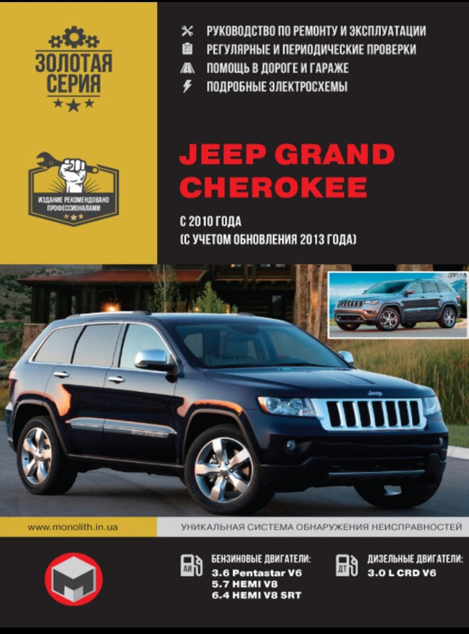
Кому нужна книга Качайте на здоровье
yadi.sk/i/L0tXQw5u3QDtkQ
Цена вопроса: 0 ₽
Пробег: 205 000 км
13 апреля 2023
Метки: своими руками
29
6
Разместить рекламу
Реклама
Машины в продаже
Комментарии
6
Войдите или зарегистрируйтесь, чтобы писать комментарии, задавать вопросы и участвовать в обсуждении.
Войти
Зарегистрироваться

Valvet45
Я езжу на BMW 7 series (F01/02)
Спасибо
1 месяц

Vadimych97
Я езжу на Jeep Grand Cherokee (WK2)
Есть на бумаге такая)
5 месяцев

Talakanec
Я езжу на Nissan Murano II
Комментарий удалён
В ЛС написал вам. По почте такой объем не отправить.
5 месяцев
Talakanec
Я езжу на Nissan Murano II
Есть. Без проблем скину.
5 месяцев
Talakanec
Я езжу на Nissan Murano II
Только осторожно. В ней очень много неточностей. Сравнивали с оригиналом на английском языке. Лично я пожалел, что купил её.
5 месяцев

Sabium
Автор
Я езжу на Jeep Grand Cherokee (WK2)
На сегодняшний день альтернативы данной книги не нашёл. У вас есть оригинал на английском языке? Не желаете поделиться?
1
5 месяцев
Посмотреть инструкция для Jeep Grand Cherokee (2012) бесплатно. Руководство относится к категории автомобили, 22 человек(а) дали ему среднюю оценку 9.1. Руководство доступно на следующих языках: английский. У вас есть вопрос о Jeep Grand Cherokee (2012) или вам нужна помощь? Задайте свой вопрос здесь
Не можете найти ответ на свой вопрос в руководстве? Вы можете найти ответ на свой вопрос ниже, в разделе часто задаваемых вопросов о Jeep Grand Cherokee (2012).
Как перевести мили в километры?
1 миля равна 1,609344 километрам, а 1 километр — 0,62137119 милям.
Где я могу узнать идентификационный номер транспортного средства Jeep?
Место размещения идентификационного номера транспортного средства зависит от марки и типа транспортного средства. Номер может быть выбит на раме транспортного средства или указан на номерном знаке. Чтобы узнать место расположения идентификационного номера транспортного средства лучше всего ознакомиться с руководством по эксплуатации Jeep Grand Cherokee (2012).
Что такое идентификационный номер транспортного средства (VIN)?
Идентификационный номер транспортного средства — уникальный для каждого транспортного средства идентификационный номер. Аббревиатура VIN расшифровывается как «Vehicle Identification Number» (Идентификационный номер транспортного средства).
Когда транспортному средству Jeep требуется техническое обслуживание?
Регулярное техническое обслуживание необходимо всем транспортным средствам. С информацией о том, как часто необходимо проходить техническое обслуживание и чему именно стоит уделять особое внимание можно ознакомиться в инструкции по техническому обслуживанию. Как правило, транспортное средство требует технического обслуживания каждые 2 года или 30 000 километров пробега.
Когда следует заменять тормозную жидкость на Jeep?
Тормозную жидкость рекомендуется менять каждые два года.
В чем разница между топливом E10 и E5?
В топливе E10 содержится до десяти процентов этанола, в то время как в E5 содержится менее пяти процентов. Соответственно, топливо E10 менее вредит окружающей среде.
Одна или несколько дверей не открываются изнутри. Что мне делать?
Скорее всего, замок оснащен защитой от детей и поэтому не может быть открыт изнутри. Процедура открытия замка с защитой от детей зависит от марки и типа замка.
Автомобильный радиоприемник не включается, что делать?
Если автомобильный радиоприемник не включен, на него не будет подаваться питание. Убедитесь, что красный провод подключен к контактному источнику питания, а желтый провод — к источнику питания постоянной мощности.
Инструкция Jeep Grand Cherokee (2012) доступно в русский?
К сожалению, у нас нет руководства для Jeep Grand Cherokee (2012), доступного в русский. Это руководство доступно в английский.
Не нашли свой вопрос? Задайте свой вопрос здесь
-
Contents
-
Table of Contents
-
Troubleshooting
-
Bookmarks
Related Manuals for Jeep Grand Cherokee 2012
Summary of Contents for Jeep Grand Cherokee 2012
-
Page 1
Grand Cherokee 2 0 1 2 O W N E R ’ S M A N U A L I n f o r m a t i o n P r o v i d e d b y :… -
Page 2
VEHICLES SOLD IN CANADA With respect to any Vehicles Sold in Canada, the name This manual illustrates and describes the operation of fea- Chrysler Group LLC shall be deemed to be deleted and the tures and equipment that are either standard or optional on name Chrysler Canada Inc. -
Page 3: Table Of Contents
TABLE OF CONTENTS SECTION PAGE …………3 INTRODUCTION .
-
Page 4
I n f o r m a t i o n P r o v i d e d b y :… -
Page 5
INTRODUCTION CONTENTS Introduction ……4 Warnings And Cautions ….8 Rollover Warning . -
Page 6: Introduction
4 INTRODUCTION INTRODUCTION handles on different road surfaces. Your driving skills Congratulations on selecting your new Chrysler Group will improve with experience. When driving off-road or LLC vehicle. Be assured that it represents precision working the vehicle, don’t overload the vehicle or expect workmanship, distinctive styling, and high quality — all the vehicle to overcome the natural laws of physics.
-
Page 7: Rollover Warning
INTRODUCTION 5 NOTE: After reviewing the owner information, it Do not attempt sharp turns, abrupt maneuvers, or other should be stored in the vehicle for convenient referenc- unsafe driving actions that can cause loss of vehicle ing and remain with the vehicle when sold. control.
-
Page 8: How To Use This Manual
6 INTRODUCTION Failure to use the driver and passenger seat belts pro- HOW TO USE THIS MANUAL vided is a major cause of severe or fatal injury. In fact, the Consult the Table of Contents to determine which section U.S. government notes that the universal use of existing contains the information you desire.
-
Page 9
INTRODUCTION 7 I n f o r m a t i o n P r o v i d e d b y :… -
Page 10: Warnings And Cautions
8 INTRODUCTION WARNINGS AND CAUTIONS This Owner’s Manual contains WARNINGS against op- erating procedures that could result in a collision or bodily injury. It also contains CAUTIONS against proce- dures that could result in damage to your vehicle. If you do not read this entire manual, you may miss important information.
-
Page 11: Vehicle Modifications/Alterations
INTRODUCTION 9 VEHICLE MODIFICATIONS/ALTERATIONS WARNING! Any modifications or alterations to this vehicle could seriously affect its roadworthiness and safety and may lead to a collision resulting in serious injury or death. Right Front Body VIN Location NOTE: It is illegal to remove or alter the VIN. I n f o r m a t i o n P r o v i d e d b y :…
-
Page 12
I n f o r m a t i o n P r o v i d e d b y :… -
Page 13: Things To Know Before Starting Your Vehicle
THINGS TO KNOW BEFORE STARTING YOUR VEHICLE CONTENTS A Word About Your Keys ….14 Vehicle Security Alarm — If Equipped ..20 ▫…
-
Page 14
12 THINGS TO KNOW BEFORE STARTING YOUR VEHICLE ▫ Using The Panic Alarm ….26 ▫ Wind Buffeting ….. . . 44 ▫… -
Page 15
THINGS TO KNOW BEFORE STARTING YOUR VEHICLE 13 ▫ Seat Belt Pretensioners ….61 ▫ Event Data Recorder (EDR) ….80 ▫… -
Page 16: A Word About Your Keys
14 THINGS TO KNOW BEFORE STARTING YOUR VEHICLE A WORD ABOUT YOUR KEYS Wireless Ignition Node (WIN) Your vehicle uses a keyless ignition system. This system The Wireless Ignition Node (WIN) operates similar to an consists of a Key Fob with Remote Keyless Entry (RKE) ignition switch.
-
Page 17: Key Fob
THINGS TO KNOW BEFORE STARTING YOUR VEHICLE 15 Key Fob The Key Fob operates the ignition switch. Insert the square end of the key fob into the ignition switch located on the instrument panel and rotate to the desired posi- tion.
-
Page 18: Removing Key Fob From Ignition
16 THINGS TO KNOW BEFORE STARTING YOUR VEHICLE To remove the emergency key, slide the mechanical latch Removing Key Fob From Ignition at the top of the Key Fob sideways with your thumb and Place the shift lever in PARK. Turn the Key Fob to the then pull the key out with your other hand.
-
Page 19
THINGS TO KNOW BEFORE STARTING YOUR VEHICLE 17 • The power window switches, radio, power sunroof (if CAUTION! (Continued) equipped), and power outlets will remain active for up • Leave the Key Fob in the ignition and either: to 10 minutes after the ignition switch is turned to the •… -
Page 20: Key-In-Ignition Reminder
18 THINGS TO KNOW BEFORE STARTING YOUR VEHICLE NOTE: The Key-In-Ignition reminder only sounds WARNING! (Continued) when the Key Fob is placed in the OFF or ACC ignition • Do not leave the key fob in or near the vehicle, and position.
-
Page 21: Replacement Keys
THINGS TO KNOW BEFORE STARTING YOUR VEHICLE 19 vehicle can be used to start and operate the vehicle. The CAUTION! system will shut the engine off in two seconds if an invalid Key Fob is used to start the engine. The Sentry Key Immobilizer system is not compat- ible with some after-market remote starting systems.
-
Page 22: Customer Key Programming
20 THINGS TO KNOW BEFORE STARTING YOUR VEHICLE Customer Key Programming CAUTION! Programming Key Fobs or RKE transmitters may be • Always remove the Key Fobs from the vehicle and performed at an authorized dealer. lock all doors when leaving the vehicle unat- General Information tended.
-
Page 23: Rearming The System
THINGS TO KNOW BEFORE STARTING YOUR VEHICLE 21 audio and visual signals, the horn will sound, the head- To Arm The System lights will turn on, park lamps and/or turn signals will Follow these steps to arm the Vehicle Security Alarm: flash repeatedly for three minutes.
-
Page 24: To Disarm The System
22 THINGS TO KNOW BEFORE STARTING YOUR VEHICLE • Cycle the vehicle ignition system out of the OFF exterior zone (refer to Keyless Enter-N-Go in Things To Know Before Starting Your Vehicle for further informa- position. tion). • For vehicles equipped with Keyless Enter-N-Go, •…
-
Page 25: Tamper Alert
THINGS TO KNOW BEFORE STARTING YOUR VEHICLE 23 • When the Vehicle Security Alarm is armed, the interior Tamper Alert power door lock switches will not unlock the doors. If something has triggered the Vehicle Security Alarm in your absence, the horn will sound three times and the The Vehicle Security Alarm is designed to protect your exterior lights blink three times when you unlock the vehicle;…
-
Page 26: Remote Keyless Entry (Rke)
24 THINGS TO KNOW BEFORE STARTING YOUR VEHICLE NOTE: NOTE: Inserting the Key Fob with RKE transmitter into • The front courtesy overhead console and door cour- the ignition switch disables the system from responding tesy lights will turn on if the dimmer control is in the to any button presses from that RKE transmitter.
-
Page 27: To Unlock The Doors
THINGS TO KNOW BEFORE STARTING YOUR VEHICLE 25 To Unlock The Doors Flash Lamps With Lock Press and release the UNLOCK button on the RKE This feature will cause the turn signal lamps to flash transmitter once to unlock the driver’s door or twice to when the doors are locked or unlocked with the RKE unlock all doors.
-
Page 28: To Lock The Doors
26 THINGS TO KNOW BEFORE STARTING YOUR VEHICLE To Lock The Doors Using The Panic Alarm Press and release the LOCK button on the RKE transmit- To turn the Panic Alarm feature on or off, press and hold ter to lock all doors. The turn signal lamps will flash and the PANIC button on the RKE transmitter for at least one the horn will chirp to acknowledge the signal.
-
Page 29: Transmitter Battery Replacement
THINGS TO KNOW BEFORE STARTING YOUR VEHICLE 27 Transmitter Battery Replacement The recommended replacement battery is one CR2032 battery. NOTE: • Perchlorate Material — special handling may apply. See www.dtsc.ca.gov/hazardouswaste/perchlorate • Do not touch the battery terminals that are on the back housing or the printed circuit board.
-
Page 30
28 THINGS TO KNOW BEFORE STARTING YOUR VEHICLE 2. Insert the tip of the emergency key or a #2 flat blade screwdriver into the slot and gently pry the two halves of the RKE transmitter apart. Make sure not to damage the seal during removal. -
Page 31: General Information
THINGS TO KNOW BEFORE STARTING YOUR VEHICLE 29 4. To assemble the RKE transmitter case, snap the two 2. Closeness to a radio transmitter such as a radio station halves together. tower, airport transmitter, and some mobile or CB radios. General Information REMOTE STARTING SYSTEM —…
-
Page 32: How To Use Remote Start
30 THINGS TO KNOW BEFORE STARTING YOUR VEHICLE • System not disabled from previous remote start event How To Use Remote Start All of the following conditions must be met before the • Vehicle theft alarm not active engine will remote start: •…
-
Page 33
THINGS TO KNOW BEFORE STARTING YOUR VEHICLE 31 Remote Start Abort Message On Electronic Vehicle To Enter Remote Start Mode Information Center (EVIC) — If Equipped Press and release the REMOTE START button The following messages will display in the EVIC if the on the RKE transmitter twice within five sec- vehicle fails to remote start or exits remote start prema- onds. -
Page 34
32 THINGS TO KNOW BEFORE STARTING YOUR VEHICLE • The engine can be started two consecutive times with equipped). Then, prior to the end of the 15 minute cycle, the RKE transmitter. However, the ignition must be press and release the START/STOP button. If the cycled by pushing the START/STOP button twice (or START/STOP button is not present, insert the Key Fob the ignition switch must be cycled to the ON/RUN… -
Page 35: Door Locks
THINGS TO KNOW BEFORE STARTING YOUR VEHICLE 33 Remote Start Comfort Systems — If Equipped panel downward. To unlock the front doors, pull the When remote start is activated, the heated steering inside door handle to the first detent. To unlock the rear wheel, and driver heated seat features will automatically doors, pull the door lock knob on the door trim panel turn on in cold weather.
-
Page 36: Power Door Locks
34 THINGS TO KNOW BEFORE STARTING YOUR VEHICLE Power Door Locks WARNING! The power door lock switch is located on each front door • For personal security and safety in the event of an panel. Press the switch to lock or unlock the doors. accident, lock the vehicle doors when you drive, as well as when you park and leave the vehicle.
-
Page 37: Child-Protection Door Lock System — Rear Doors
THINGS TO KNOW BEFORE STARTING YOUR VEHICLE 35 If you press the door lock switch while the Key Fob is in Automatic Unlock On Exit Feature — If Equipped the ignition switch and the driver’s door is open, the If Auto Unlock is enabled, this feature will unlock all the doors will not lock.
-
Page 38
36 THINGS TO KNOW BEFORE STARTING YOUR VEHICLE 3. Repeat steps 1 and 2 for the opposite rear door. Child-Protection Door Lock Function Child-Protection Door Lock Location WARNING! Avoid trapping anyone in a vehicle in a collision. Remember that the rear doors can only be opened from the outside when the Child-Protection locks are engaged (locked). -
Page 39: Keyless Enter-N-Go
THINGS TO KNOW BEFORE STARTING YOUR VEHICLE 37 NOTE: For emergency exit from the rear seats when the NOTE: • Passive Entry may be programmed ON/OFF; refer to Child-Protection Door Lock System is engaged, manually raise the door lock knob to the unlocked position, roll “Electronic Vehicle Information Center (EVIC)/ down the window, and open the door using the outside Personal Settings (Customer-Programmable Fea-…
-
Page 40
38 THINGS TO KNOW BEFORE STARTING YOUR VEHICLE To Unlock From The Driver’s Side: NOTE: If “Unlock All Doors 1st Press” is programmed With a valid Passive Entry RKE transmitter within 5 ft all doors will unlock when you grab hold of the driver’s (1.5 m) of the driver’s door handle, grab the driver’s front front door handle. -
Page 41
THINGS TO KNOW BEFORE STARTING YOUR VEHICLE 39 Preventing Inadvertent Locking Of Passive Entry RKE To Enter The Liftgate Transmitter In Vehicle With a valid Passive Entry RKE transmitter within 3 ft To minimize the possibility of unintentionally locking a (1.0 m) of the liftgate, press the button on the right side of Passive Entry RKE transmitter inside your vehicle, the the chrome accent bar, which is located on the liftgate… -
Page 42
40 THINGS TO KNOW BEFORE STARTING YOUR VEHICLE NOTE: If “Unlock All Doors 1st Press” is programmed in EVIC, all doors will unlock when you push the button on the liftgate. If Unlock Driver Door 1st press is programmed in EVIC, the liftgate and Flipper glass will unlock when you press the button on the liftgate For further information, refer to “Electronic Vehicle Informa- tion… -
Page 43: Windows
THINGS TO KNOW BEFORE STARTING YOUR VEHICLE 41 NOTE: passenger and rear passenger door windows. The win- • After pressing the door handle LOCK button, you dow controls will operate only when the ignition switch must wait two seconds before you can lock or unlock is in the ON/RUN or ACC position.
-
Page 44
42 THINGS TO KNOW BEFORE STARTING YOUR VEHICLE The power window switches remain active for 10 min- WARNING! utes after the ignition has been turned OFF. Opening either front door will cancel this feature. Never leave children in a vehicle with the key in the ignition switch or leave a vehicle with Keyless Enter- Auto Up Feature With Anti-Pinch Protection —… -
Page 45
THINGS TO KNOW BEFORE STARTING YOUR VEHICLE 43 during Auto Up. If this happens, pull the switch lightly to Window Lockout Button the first detent and hold it to close the window manually. The Window Lockout button on the driver’s door allows you to disable the window controls on the rear doors. -
Page 46: Wind Buffeting
44 THINGS TO KNOW BEFORE STARTING YOUR VEHICLE Wind Buffeting Wind buffeting can be described as the perception of pressure on the ears or a helicopter-type sound in the ears. Your vehicle may exhibit wind buffeting with the windows down, or the sunroof (if equipped) in certain open or partially open positions.
-
Page 47: Liftgate Flipper Glass
THINGS TO KNOW BEFORE STARTING YOUR VEHICLE 45 Liftgate Flipper Glass Once the liftgate flipper glass has been opened, connec- The liftgate flipper glass is also unlocked when the tion to the rear window wiper is interrupted, preventing liftgate is unlocked. To open the flipper glass, push up on activation of the rear wiper blade while the flipper glass the window switch located on the liftgate.
-
Page 48: Power Liftgate — If Equipped
46 THINGS TO KNOW BEFORE STARTING YOUR VEHICLE Power Liftgate — If Equipped To operate the power liftgate manually in the open The power liftgate may be opened by pulling direction, pull the liftgate handle once to initiate a power up on the liftgate handle or by pressing the cycle and then pull the handle a second time to put LIFTGATE button on the Remote Keyless Entry…
-
Page 49
THINGS TO KNOW BEFORE STARTING YOUR VEHICLE 47 • If anything obstructs the power liftgate while it is WARNING! closing or opening, the liftgate will automatically reverse to the closed or open position, provided it During power operation, personal injury or cargo meets sufficient resistance. -
Page 50
48 THINGS TO KNOW BEFORE STARTING YOUR VEHICLE • If the liftgate handle is pulled while the power liftgate WARNING! is opening, the liftgate motor will disengage to allow • Driving with the liftgate open can allow poison- manual operation. ous exhaust gases into your vehicle. -
Page 51: Occupant Restraints
THINGS TO KNOW BEFORE STARTING YOUR VEHICLE 49 • Knee bolsters for front seat occupants OCCUPANT RESTRAINTS Some of the most important safety features in your • Front seat belts incorporate pretensioners that may vehicle are the restraint systems: enhance occupant protection by managing occupant •…
-
Page 52
50 THINGS TO KNOW BEFORE STARTING YOUR VEHICLE infant and child restraint systems. For more information Children that are not big enough to wear the vehicle seat on LATCH, refer to Lower Anchors and Tether for belt properly (see section on Child Restraints) should be CHildren (LATCH). -
Page 53
THINGS TO KNOW BEFORE STARTING YOUR VEHICLE 51 3. The driver and front passenger seats should be WARNING! moved back as far as practical to allow the Advanced • Relying on the air bags alone could lead to more Front Air Bags room to inflate. severe injuries in a collision. -
Page 54: Lap/Shoulder Belts
52 THINGS TO KNOW BEFORE STARTING YOUR VEHICLE Research has shown that seat belts save lives, and they WARNING! (Continued) can reduce the seriousness of injuries in a collision. Some • Supplemental Side Air Bag Inflatable Curtain of the worst injuries happen when people are thrown (SABIC) and Seat-Mounted Side Air Bags (SAB) from the vehicle.
-
Page 55: Lap/Shoulder Belt Operating Instructions
THINGS TO KNOW BEFORE STARTING YOUR VEHICLE 53 WARNING! WARNING! (Continued) • It is dangerous to ride in a cargo area, inside or • Wearing a seat belt incorrectly is dangerous. Seat outside of a vehicle. In a collision, people riding in belts are designed to go around the large bones of these areas are more likely to be seriously injured your body.
-
Page 56
54 THINGS TO KNOW BEFORE STARTING YOUR VEHICLE 2. The seat belt latch plate is above the back of your seat. 3. When the belt is long enough to fit, insert the latch Grasp the latch plate and pull out the belt. Slide the latch plate into the buckle until you hear a “click.”… -
Page 57
THINGS TO KNOW BEFORE STARTING YOUR VEHICLE 55 WARNING! WARNING! (Continued) • A belt that is worn under your arm is dangerous. • A belt that is buckled into the wrong buckle will Your body could strike the inside surfaces of the not protect you properly. -
Page 58
56 THINGS TO KNOW BEFORE STARTING YOUR VEHICLE 4. Position the lap belt across your thighs, below your 5. Position the shoulder belt on your chest so that it is abdomen. To remove slack in the lap portion, pull up a comfortable and not resting on your neck. -
Page 59: Lap/Shoulder Belt Untwisting Procedure
THINGS TO KNOW BEFORE STARTING YOUR VEHICLE 57 6. To release the belt, push the red button on the buckle. Lap/Shoulder Belt Untwisting Procedure The belt will automatically retract to its stowed position. Use the following procedure to untwist a twisted lap/ If necessary, slide the latch plate down the webbing to shoulder belt.
-
Page 60: Adjustable Upper Shoulder Belt Anchorage
58 THINGS TO KNOW BEFORE STARTING YOUR VEHICLE Adjustable Upper Shoulder Belt Anchorage As a guide, if you are shorter than average, you will In the front seating positions, the shoulder belt can be prefer a lower position, and if you are taller than average, adjusted upward or downward to position the belt away you will prefer a higher position.
-
Page 61: Automatic Locking Retractor Mode (Alr) — If Equipped
THINGS TO KNOW BEFORE STARTING YOUR VEHICLE 59 additional information, refer to “Installing Child Re- out only the amount of webbing necessary to comfort- straints Using The Vehicle Seat Belt” under the “Child ably wrap around the occupant’s mid-section. Slide the Restraints”…
-
Page 62: Energy Management Feature
60 THINGS TO KNOW BEFORE STARTING YOUR VEHICLE 3. Allow the belt to retract. As the belt retracts, you will Energy Management Feature hear a clicking sound. This indicates the safety belt is This vehicle has a safety belt system with an Energy now in the Automatic Locking Mode.
-
Page 63: Seat Belt Pretensioners
THINGS TO KNOW BEFORE STARTING YOUR VEHICLE 61 Seat Belt Pretensioners identified by any markings, only through visual inspec- The seat belts for both front seating positions are tion of the head restraint. The head restraint will be split equipped with pretensioning devices that are designed to in two halves, with the front half being soft foam and remove slack from the seat belt in the event of a collision.
-
Page 64
62 THINGS TO KNOW BEFORE STARTING YOUR VEHICLE However if during a front impact, a secondary rear CAUTION! impact occurs, the AHR may deploy based on several factors, including the severity and type of the impact. All occupants, including the driver, should not oper- ate a vehicle or sit in a vehicle’s seat until the head restraints are placed in their proper positions in order to minimize the risk of neck injury in the event of a… -
Page 65
THINGS TO KNOW BEFORE STARTING YOUR VEHICLE 63 1. Grasp the deployed AHR from the rear seat. 3. Pull down then rearward towards the rear of the vehicle then down to engage the locking mechanism. Hand Positioning Points On AHR 2. -
Page 66
64 THINGS TO KNOW BEFORE STARTING YOUR VEHICLE AHR In Reset Position 3 — Final Downward Movement To Engage Locking Mechanism NOTE: 4. The AHR front soft foam and trim half should lock • If you have difficulties or problems resetting the into the back decorative plastic half. -
Page 67: Enhanced Seat Belt Use Reminder System (Beltalert )
THINGS TO KNOW BEFORE STARTING YOUR VEHICLE 65 Enhanced Seat Belt Use Reminder System unbuckled while traveling at speeds greater than 5 mph (BeltAlert ) (8 km/h), BeltAlert will provide both audio and visual BeltAlert is a feature intended to remind the driver and notification.
-
Page 68: Seat Belt Lock Out
66 THINGS TO KNOW BEFORE STARTING YOUR VEHICLE Seat Belt Lock Out extender should be used only if the existing belt is not The center rear seat belt system has a lock out feature that long enough. When it is not required, remove the ex- will not allow you to extract the center webbing unless tender and store it.
-
Page 69
THINGS TO KNOW BEFORE STARTING YOUR VEHICLE 67 instrument panel, above the glove compartment. The The Advanced Front Air Bags have a multistage inflator words SRS AIRBAG are embossed on the air bag covers. design. This allows the air bag to have different rates of inflation based on several factors, including the severity and type of collision. -
Page 70
68 THINGS TO KNOW BEFORE STARTING YOUR VEHICLE • Instrument Panel This vehicle is equipped with Supplemental Seat- Mounted Side Air Bags (SAB) to provide enhanced • Knee Impact Bolster protection for an occupant during a side impact. The • Driver Advanced Front Air Bag Supplemental Seat-Mounted Side Air Bags are located in the outboard side of the front seats. -
Page 71: Advanced Front Air Bag Features
THINGS TO KNOW BEFORE STARTING YOUR VEHICLE 69 Advanced Front Air Bag Features WARNING! The Advanced Front Air Bag system has multistage • No objects should be placed over or near the air driver and front passenger air bags. This system provides bag on the instrument panel, because any such output appropriate to the severity and type of collision as objects could cause harm if the vehicle is in a…
-
Page 72
70 THINGS TO KNOW BEFORE STARTING YOUR VEHICLE Supplemental Seat-Mounted Side Air Bags (SAB) When the air bag deploys, it opens the seam between the Supplemental Seat-Mounted Side Air Bags (SAB) may front and side of the seat’s trim cover. Each air bag provide enhanced protection to help protect an occupant deploys independently;… -
Page 73
THINGS TO KNOW BEFORE STARTING YOUR VEHICLE 71 • Should a vehicle rollover occur, the pretensioners and/or SAB and SABIC air bags on both sides of the vehicle may deploy. The system includes side impact sensors that are cali- brated to deploy the Supplemental Seat-Mounted Side Air Bags and SABIC air bags during impacts that require side air bag occupant protection. -
Page 74: Air Bag Deployment Sensors And Controls
72 THINGS TO KNOW BEFORE STARTING YOUR VEHICLE Along with seat belts and pretensioners, Advanced Front WARNING! (Continued) Air Bags work with the knee bolsters to provide im- • Do not use accessory seat covers or place objects proved protection for the driver and front passenger. Side between you and the side air bags;…
-
Page 75
THINGS TO KNOW BEFORE STARTING YOUR VEHICLE 73 Advanced Front Air Bags are designed to provide addi- Because air bag sensors measure vehicle deceleration tional protection by supplementing the seat belts in over time, vehicle speed and damage by themselves are certain frontal collisions depending on several factors, not good indicators of whether or not an air bag should including the severity and type of collision. -
Page 76
74 THINGS TO KNOW BEFORE STARTING YOUR VEHICLE Also, the ORC turns on the Air Bag Warning WARNING! Light in the instrument panel for approxi- mately four to eight seconds for a self-check Ignoring the Air Bag Warning Light in your instru- when the ignition is first turned on. -
Page 77
THINGS TO KNOW BEFORE STARTING YOUR VEHICLE 75 are possible, based on the collision type and severity. The Based on several factors, including the severity and type steering wheel hub trim cover and the upper right side of of collision, the side air bag inflator on the crash side of the instrument panel separate and fold out of the way as the vehicle may be triggered, releasing a quantity of the air bags inflate to their full size. -
Page 78
76 THINGS TO KNOW BEFORE STARTING YOUR VEHICLE A quantity of non-toxic gas is generated to inflate the Front And Side Impact Sensors SABIC. The inflating SABIC pushes the outside edge of In front and side impacts, front and side impact sensors the headliner out of the way and covers the window. -
Page 79
THINGS TO KNOW BEFORE STARTING YOUR VEHICLE 77 • Unlock the doors automatically. floor. They are not caused by contact with chemicals. They are not permanent and normally heal quickly. In order to reset the Enhanced Accident Response System However, if you haven’t healed significantly within a functions after an event, the ignition switch must be few days, or if you have any blistering, see your doctor changed from IGN ON to IGN OFF. -
Page 80
78 THINGS TO KNOW BEFORE STARTING YOUR VEHICLE Maintaining Your Air Bag System WARNING! WARNING! Deployed air bags and seat belt pretensioners cannot protect you in another collision. Have the air bags, • Modifications to any part of the air bag system seat belt pretensioners, and the front seat belt retrac- could cause it to fail when you need it. -
Page 81
THINGS TO KNOW BEFORE STARTING YOUR VEHICLE 79 Air Bag Warning Light WARNING! (Continued) You will want to have the air bags ready to • Do not attempt to modify any part of your air bag inflate for your protection in a collision. The system. -
Page 82: Event Data Recorder (Edr)
80 THINGS TO KNOW BEFORE STARTING YOUR VEHICLE • Whether or not the driver and passenger safety belts NOTE: If the speedometer, tachometer, or any engine related gauges are not working, the Occupant Restraint were buckled/fastened; Controller (ORC) may also be disabled. The air bags may •…
-
Page 83: Child Restraints
THINGS TO KNOW BEFORE STARTING YOUR VEHICLE 81 In addition to the vehicle manufacturer, other parties, seat Owner’s Manual to ensure you have the right seat such as law enforcement, that have the special equip- for your child. Use the restraint that is correct for your ment, can read the information if they have access to the child.
-
Page 84
82 THINGS TO KNOW BEFORE STARTING YOUR VEHICLE facing child safety seat. Two types of child restraints can WARNING! be used rearward-facing: infant carriers and convertible • Rearward-facing child seats must never be used in child seats. the front seat of a vehicle with the front passenger The infant carrier is only used rearward-facing in the air bag. -
Page 85
THINGS TO KNOW BEFORE STARTING YOUR VEHICLE 83 Here are some tips for getting the most out of your child restraint and slide the latch plate into the buckle. Then, restraint: pull the shoulder belt until it is fully extended from the retractor. -
Page 86
84 THINGS TO KNOW BEFORE STARTING YOUR VEHICLE NOTE: For additional information, refer to All children whose weight or height is above the www.seatcheck.org or call 1–866–SEATCHECK. Cana- forward-facing limit for the child seat should use a dian residents should refer to Transport Canada’s web- belt-positioning booster seat until the vehicle’s seat belts site for additional information: http://www.tc.gc.ca/ fit properly. -
Page 87
THINGS TO KNOW BEFORE STARTING YOUR VEHICLE 85 • Check belt fit periodically. A child’s squirming or LATCH-compatible child restraint systems are now avail- slouching can move the belt out of position. able. However, because the lower anchorages are to be introduced over a period of years, child restraint systems •… -
Page 88
86 THINGS TO KNOW BEFORE STARTING YOUR VEHICLE The rear outboard seating positions have lower center position. If your child restraints are not LATCH- anchorages capable accommodating compatible, you can only install the child restraints using LATCH-compatible child seats having flexible, the vehicle’s seat belts. -
Page 89
THINGS TO KNOW BEFORE STARTING YOUR VEHICLE 87 Latch Anchorages Pulling Down The Carpet Floor Panel To Access Top Tether Strap In addition, there are top tether strap anchorages behind each rear seating position located on the back of the seat. To access the top tether strap anchorages behind the rear seat, pull the carpeted floor panel away from the seat back, this will expose the top tether strap anchorages. -
Page 90
88 THINGS TO KNOW BEFORE STARTING YOUR VEHICLE Many, but not all, restraint systems will be equipped with separate straps on each side, with each having a hook or connector for attachment to the lower anchorage and a means of adjusting the tension in the strap. Forward- facing toddler restraints and some rear-facing infant restraints will also be equipped with a tether strap, a hook for attachment to the tether strap anchorage and a… -
Page 91
THINGS TO KNOW BEFORE STARTING YOUR VEHICLE 89 gap panel. They are not visible until you fold the gap secure a Child Restraint System (CRS). These types of panel down. Do not use the cargo tie down hooks seat belts are designed to keep the lap portion of the seat located on the floor behind the seat. -
Page 92
90 THINGS TO KNOW BEFORE STARTING YOUR VEHICLE Installing a Child Restraint with an ALR: the upward position. To access the center seat arm rest tether first lower the arm rest. The tether is located 1. To install a child restraint with ALR, first, pull enough behind the armrest and hooked onto the plastic seat of the seat belt webbing from the retractor to route it backing. -
Page 93
THINGS TO KNOW BEFORE STARTING YOUR VEHICLE 91 Pull down on the tether to unhook it from the plastic seat and attach the hook to the top tether anchor located on the backing, then raise the armrest and attach the tether hook back of the seat. -
Page 94
92 THINGS TO KNOW BEFORE STARTING YOUR VEHICLE Top Tether Strap Anchorage (Located on Seatback) Top Tether Strap Mounting I n f o r m a t i o n P r o v i d e d b y :… -
Page 95: Engine Break-In Recommendations
THINGS TO KNOW BEFORE STARTING YOUR VEHICLE 93 behind the gap panel. Please note the top tether anchor- WARNING! ages are not visible until you fold the gap panel down. • An incorrectly anchored tether strap could lead to Do not use the cargo tie down hooks located on the floor behind the seats.
-
Page 96: Safety Tips
94 THINGS TO KNOW BEFORE STARTING YOUR VEHICLE While cruising, brief full-throttle acceleration within the should be considered a normal part of the break-in and limits of local traffic laws contributes to a good break-in. not interpreted as an indication of difficulty. Wide-open throttle acceleration in low gear can be detri- SAFETY TIPS mental and should be avoided.
-
Page 97: Exhaust Gas
THINGS TO KNOW BEFORE STARTING YOUR VEHICLE 95 WARNING! (Continued) WARNING! (Continued) • Do not allow people to ride in any area of your • Do not run the engine in a closed garage or in vehicle that is not equipped with seats and seat confined areas any longer than needed to move belts.
-
Page 98: Safety Checks You Should Make Inside The Vehicle
96 THINGS TO KNOW BEFORE STARTING YOUR VEHICLE vehicle, or when the underside or rear of the vehicle is Air Bag Warning Light damaged, have a competent mechanic inspect the com- The light should come on and remain on for four to eight plete exhaust system and adjacent body areas for broken, seconds as a bulb check when the ignition switch is first damaged, deteriorated, or mispositioned parts.
-
Page 99
THINGS TO KNOW BEFORE STARTING YOUR VEHICLE 97 WARNING! WARNING! (Continued) • Check mounting of mats on a regular basis. Al- Pedals that cannot move freely can cause loss of ways properly reinstall and secure floor mats that vehicle control and increase the risk of serious per- have been removed for cleaning. -
Page 100: Periodic Safety Checks You Should Make Outside The Vehicle
98 THINGS TO KNOW BEFORE STARTING YOUR VEHICLE Periodic Safety Checks You Should Make Outside Door Latches The Vehicle Check for positive closing, latching, and locking. Tires Fluid Leaks Examine tires for excessive tread wear and uneven wear Check area under vehicle after overnight parking for fuel, patterns.
-
Page 101: Understanding The Features Of Your Vehicle
UNDERSTANDING THE FEATURES OF YOUR VEHICLE CONTENTS ▫ Tilt Mirrors In Reverse (Available With Mirrors ……107 Memory Seat Only) —…
-
Page 102
100 UNDERSTANDING THE FEATURES OF YOUR VEHICLE ▫ Phone Call Features ….130 ▫ Power Lumbar — If Equipped … 160 ▫… -
Page 103
UNDERSTANDING THE FEATURES OF YOUR VEHICLE 101 ▫ Daytime Running Lights — If Equipped ..183 Driver Memory Seat — If Equipped ..174 ▫ Setting Memory Positions And Linking ▫… -
Page 104
102 UNDERSTANDING THE FEATURES OF YOUR VEHICLE ▫ Lane Change Assist ….188 Electronic Speed Control ….197 ▫… -
Page 105
UNDERSTANDING THE FEATURES OF YOUR VEHICLE 103 ▫ To Cancel ……207 Parksense Rear Park Assist — If Equipped . . . 229 ▫… -
Page 106
104 UNDERSTANDING THE FEATURES OF YOUR VEHICLE ▫ Turning Parkview On Or Off — Without ▫ Troubleshooting Tips ….250 Navigation/Multimedia Radio … 240 ▫… -
Page 107
UNDERSTANDING THE FEATURES OF YOUR VEHICLE 105 ▫ Sunroof Maintenance ….258 Commandview Sunroof With Power Shade — If Equipped ……255 ▫… -
Page 108
106 UNDERSTANDING THE FEATURES OF YOUR VEHICLE Cargo Area Features ….269 Rear Window Features ….275 ▫… -
Page 109: Mirrors
UNDERSTANDING THE FEATURES OF YOUR VEHICLE 107 MIRRORS Inside Day/Night Mirror A two-point pivot system allows for horizontal and vertical adjustment of the mirror. Adjust the mirror to center on the view through the rear window. The mirror should be adjusted while set in the day position (toward the windshield).
-
Page 110: Automatic Dimming Mirror — If Equipped
108 UNDERSTANDING THE FEATURES OF YOUR VEHICLE Automatic Dimming Mirror — If Equipped This mirror automatically adjusts for headlight glare from vehicles behind you. You can turn the feature on or off by pressing the button at the base of the mirror. A light in the button will illuminate to indicate when the dim- ming feature is activated.
-
Page 111: Outside Mirrors
UNDERSTANDING THE FEATURES OF YOUR VEHICLE 109 Outside Mirrors Outside Mirrors Folding Feature To receive maximum benefit, adjust the outside mirrors All outside mirrors are hinged and may be moved either to center on the adjacent lane of traffic with a slight forward or rearward to resist damage.
-
Page 112: Heated Mirrors — If Equipped
110 UNDERSTANDING THE FEATURES OF YOUR VEHICLE mirror, press the mirror select button for the mirror that Power mirror preselected positions can be controlled by you want to adjust. Using the mirror control switch, press the optional Memory Seat Feature. Refer to “Driver on any of the four arrows for the direction that you want Memory Seat”…
-
Page 113: Illuminated Vanity Mirrors
UNDERSTANDING THE FEATURES OF YOUR VEHICLE 111 shifted out of REVERSE position. Each stored memory setting will have an associated Tilt Mirrors in Reverse position. NOTE: The Tilt Mirrors in Reverse feature is not en- abled when delivered from the factory. The Tilt Mirrors in Reverse feature can be enabled or disabled in the Elec- tronic Vehicle Information Center (EVIC).
-
Page 114: Blind Spot Monitoring — If Equipped
112 UNDERSTANDING THE FEATURES OF YOUR VEHICLE BLIND SPOT MONITORING — IF EQUIPPED When the vehicle is started, the BSM warning light will The Blind Spot Monitoring (BSM) system uses two radar- momentarily illuminate in both outside rear view mirrors based sensors, located inside the rear bumper fascia, to to let the driver know that the system is operational.
-
Page 115
UNDERSTANDING THE FEATURES OF YOUR VEHICLE 113 • The BSM system detection zone DOES NOT change if your vehicle is towing a trailer. Therefore, visually verify the adjacent lane is clear for both your vehicle and trailer before making a lane change. If the trailer or other object (i.e., bicycle, sports equipment) extends beyond the side of your vehicle, this may result in the BSM warning light remaining illuminated the entire… -
Page 116
114 UNDERSTANDING THE FEATURES OF YOUR VEHICLE The BSM system notifies the driver of objects in the The BSM system monitors the detection zone from three detection zones by illuminating the BSM warning light different entry points (side, rear, front) while driving to located in the outside mirrors in addition to sounding an see if an alert is necessary. -
Page 117
UNDERSTANDING THE FEATURES OF YOUR VEHICLE 115 Entering From The Rear Vehicles that come up from behind your vehicle on either side and enter the rear detection zone with a relative speed of less than 30 mph (48 km/h). Side Monitoring Rear Monitoring I n f o r m a t i o n P r o v i d e d b y :… -
Page 118
116 UNDERSTANDING THE FEATURES OF YOUR VEHICLE Overtaking Traffic If you pass another vehicle slowly (with a relative speed less than 10 mph (16 km/h) and the vehicle remains in the blind spot for approximately 1.5 seconds, the warning light will be illuminated. If the difference in speed between the two vehicles is greater than 10 mph (16 km/h), the warning light will not illuminate. -
Page 119
UNDERSTANDING THE FEATURES OF YOUR VEHICLE 117 Stationary Objects Opposing Traffic The BSM system will not alert you of objects that are traveling in the opposite direction of the vehicle in adjacent lanes. I n f o r m a t i o n P r o v i d e d b y :… -
Page 120: Rear Cross Path
118 UNDERSTANDING THE FEATURES OF YOUR VEHICLE WARNING! The Blind Spot Monitoring system is only an aid to help detect objects in the blind spot zones. The BSM system is not designed to detect pedestrians, bicy- clists, or animals. Even if your vehicle is equipped with the BSM system, always check your vehicles mirrors, glance over your shoulder, and use your turn signal before changing lanes.
-
Page 121: Modes Of Operation
UNDERSTANDING THE FEATURES OF YOUR VEHICLE 119 NOTE: In a parking lot situation, oncoming vehicles can Modes Of Operation be obscured by vehicles parked on either side. If the Three selectable modes of operation are available in the sensors are blocked by other structures or vehicles, the Electronic Vehicle Information Center (EVIC).
-
Page 122: Uconnect™ Phone — If Equipped
120 UNDERSTANDING THE FEATURES OF YOUR VEHICLE signal is then activated, and it corresponds to an alert Blind Spot Alert Off present on that side of the vehicle, an audible chime will When the BSM system is turned off there will be no also be sounded.
-
Page 123
• www.dodge.com/uconnect system. Only one linked (or paired) mobile phone can be • www.jeep.com/uconnect used with the system at a time. The system is available in English, Spanish, or French languages. -
Page 124
122 UNDERSTANDING THE FEATURES OF YOUR VEHICLE Voice Command Button WARNING! Actual button location may vary with the ra- dio. The individual buttons are described in the Any voice commanded system should be used only “Operation” section. in safe driving conditions following local laws and phone use. -
Page 125: Operation
UNDERSTANDING THE FEATURES OF YOUR VEHICLE 123 Operation example, you can use the compound form voice Voice commands can be used to operate the Uconnect™ command “Phonebook New Entry”, or you can break Phone and to navigate through the Uconnect™ Phone the compound form command into two voice com- menu structure.
-
Page 126
124 UNDERSTANDING THE FEATURES OF YOUR VEHICLE • When prompted, after the beep, say “Pair a Device” Cancel Command At any prompt, after the beep, you can say “Cancel” and and follow the audible prompts. you will be returned to the main menu. However, in a •… -
Page 127
UNDERSTANDING THE FEATURES OF YOUR VEHICLE 125 phone to use if multiple mobile phones are in the Call By Saying A Name vehicle at the same time. For example, if priority three • Press the button to begin. and priority five phones are present in the vehicle, the •… -
Page 128
126 UNDERSTANDING THE FEATURES OF YOUR VEHICLE Add Names To Your Uconnect™ Phonebook After you are finished adding an entry into the phone- book, you will be given the opportunity to add more NOTE: Adding names to the Uconnect™ Phonebook is phone numbers to the current entry or to return to the recommended when the vehicle is not in motion. -
Page 129
UNDERSTANDING THE FEATURES OF YOUR VEHICLE 127 • To call a name from the Uconnect™ Phonebook or • Only the mobile phone’s phonebook is downloaded. downloaded Phonebook, follow the procedure in SIM card phonebook is not part of the Mobile phone- “Call by Saying a Name”… -
Page 130
128 UNDERSTANDING THE FEATURES OF YOUR VEHICLE • After the “Ready” prompt and the following beep, say mobile and a home number, but you can add “John “Phonebook Edit Entry”. Doe’s” work number later using the “Phonebook Edit Entry” feature. •… -
Page 131
UNDERSTANDING THE FEATURES OF YOUR VEHICLE 129 • After you enter the name, the Uconnect™ Phone will • Note that only the phonebook in the current language ask you which designation you wish to delete: home, is deleted. work, mobile, other, or all. Say the designation you •… -
Page 132: Phone Call Features
130 UNDERSTANDING THE FEATURES OF YOUR VEHICLE • The Uconnect™ Phone will then prompt you as to the call, press and hold the button until you hear a single number designation you wish to call. beep, indicating that the incoming call was rejected. •…
-
Page 133
UNDERSTANDING THE FEATURES OF YOUR VEHICLE 131 call. The first call will be on hold while the second call is Conference Call in progress. To go back to the first call, refer to “Toggling When two calls are in progress (one active and one on Between Calls”… -
Page 134
132 UNDERSTANDING THE FEATURES OF YOUR VEHICLE Call Termination Call Continuation To end a call in progress, momentarily press the Call continuation is the progression of a phone call on the button. Only the active call(s) will be terminated and if Uconnect™… -
Page 135: Uconnect™ Phone Features
UNDERSTANDING THE FEATURES OF YOUR VEHICLE 133 Uconnect™ Phone Features Emergency Assistance If you are in an emergency and the mobile phone is Language Selection reachable: To change the language that the Uconnect™ Phone is • Pick up the phone and manually dial the emergency using: number for your area.
-
Page 136
134 UNDERSTANDING THE FEATURES OF YOUR VEHICLE Canada and 060 for Mexico). The number dialed may Towing Assistance not be applicable with the available mobile service and If you need towing assistance: area. • Press the button to begin. • If supported, this number may be programmable on •… -
Page 137
UNDERSTANDING THE FEATURES OF YOUR VEHICLE 135 Paging When calling a number with your Uconnect™ Phone that To learn how to page, refer to “Working with Automated normally requires you to enter in a touch-tone sequence Systems”. Paging works properly except for pagers of on your mobile phone keypad, you can press the certain companies, which time out a little too soon to button and say the sequence you wish to enter, followed… -
Page 138
136 UNDERSTANDING THE FEATURES OF YOUR VEHICLE The Uconnect™ Phone will then send the corresponding Turning Confirmation Prompts ON/OFF phone number associated with the phonebook entry, as Turning confirmation prompts off will stop the system tones over the phone. from confirming your choices (e.g., the Uconnect™ Phone will not repeat a phone number before you dial it). -
Page 139: Advanced Phone Connectivity
UNDERSTANDING THE FEATURES OF YOUR VEHICLE 137 Dialing Using The Mobile Phone Keypad Mute/Un-Mute (Mute OFF) You can dial a phone number with your mobile phone When you mute the Uconnect™ Phone, you will still be keypad and still use the Uconnect™ Phone (while dialing able to hear the conversation coming from the other via the mobile phone keypad, the user must exercise party, but the other party will not be able to hear you.
-
Page 140
138 UNDERSTANDING THE FEATURES OF YOUR VEHICLE • When prompted, say “List Phones”. from your Uconnect™ Phone paired mobile phone to the Uconnect™ Phone or vice versa, press the button • The Uconnect™ Phone will play the phone names of and say “Transfer Call”. -
Page 141: Things You Should Know About Your Uconnect™ Phone
UNDERSTANDING THE FEATURES OF YOUR VEHICLE 139 • The selected phone will be used for the next phone Things You Should Know About Your Uconnect™ call. If the selected phone is not available, the Phone Uconnect™ Phone will return to using the highest Uconnect™…
-
Page 142
140 UNDERSTANDING THE FEATURES OF YOUR VEHICLE You can either press the Uconnect™ Phone button to Voice Command restore the factory setting or repeat the words and • For best performance, adjust the rearview mirror to phrases when prompted by the Uconnect™ Phone. For provide at least ⁄… -
Page 143
UNDERSTANDING THE FEATURES OF YOUR VEHICLE 141 • fully closed windows, • Numbers must be spoken in single digits. “800” must be spoken “eight-zero-zero” not “eight hundred”. • dry weather condition. • You can say “O” (letter “O”) for “0” (zero). •… -
Page 144
142 UNDERSTANDING THE FEATURES OF YOUR VEHICLE • fully closed windows, Uconnect™ Phone can read or send new messages on • dry weather conditions, and your phone. • operation from the driver’s seat. Read Messages: • Performance, such as audio clarity, echo, and loudness If you receive a new text message while your phone is to a large degree rely on the phone and network, and connected to Uconnect™… -
Page 145
UNDERSTANDING THE FEATURES OF YOUR VEHICLE 143 Send Messages: 3. Where are you? You can send messages using Uconnect™ Phone. To send 4. I need more direction. a new message: 5. L O L • Press the button. 6. Why •… -
Page 146
144 UNDERSTANDING THE FEATURES OF YOUR VEHICLE 16. Can this wait? Bluetooth Communication Link Mobile phones have been found to lose connection to the 17. Bye for now Uconnect™ Phone. When this happens, the connection 18. When can we meet can generally be reestablished by switching the phone off/on. -
Page 147
UNDERSTANDING THE FEATURES OF YOUR VEHICLE 145 I n f o r m a t i o n P r o v i d e d b y :… -
Page 148
146 UNDERSTANDING THE FEATURES OF YOUR VEHICLE I n f o r m a t i o n P r o v i d e d b y :… -
Page 149
UNDERSTANDING THE FEATURES OF YOUR VEHICLE 147 I n f o r m a t i o n P r o v i d e d b y :… -
Page 150
148 UNDERSTANDING THE FEATURES OF YOUR VEHICLE Voice Commands Voice Commands Primary Alternate(s) Primary Alternate(s) zero call cancel confirmation prompts three continue four delete five dial download seven edit eight emergency nine English star (*) erase all plus (+) Espanol pound (#) Francais add location… -
Page 151
UNDERSTANDING THE FEATURES OF YOUR VEHICLE 149 Voice Commands Voice Commands Primary Alternate(s) Primary Alternate(s) language return to main menu return or main menu list names select phone select list phones send mobile set up phone settings or phone set up mute towing assistance mute off… -
Page 152: General Information
150 UNDERSTANDING THE FEATURES OF YOUR VEHICLE General Information NOTE: Take care to speak into the Voice Interface This device complies with Part 15 of the FCC rules and System as calmly and normally as possible. The ability of RSS 210 of Industry Canada. Operation is subject to the the Voice Interface System to recognize user voice com- following conditions: mands may be negatively affected by rapid speaking or a…
-
Page 153: Commands
UNDERSTANDING THE FEATURES OF YOUR VEHICLE 151 If you ever wish to interrupt the system while it lists The system will best recognize your speech if the win- options, press the Voice Command button, listen dows are closed, and the heater/air conditioning fan is for the beep, and say your command.
-
Page 154
152 UNDERSTANDING THE FEATURES OF YOUR VEHICLE • “Memo” (to switch to the memo recorder) Changing the Volume • “Setup” (to switch to system setup) 1. Start a dialogue by pressing the Voice Command button. Radio AM 2. Say a command (e.g., “Help”). To switch to the AM band, say “AM”… -
Page 155
UNDERSTANDING THE FEATURES OF YOUR VEHICLE 153 • “Next Station” (to select the next station) • “List Channel” (to hear a list of available channels) • “Previous Station” (to select the previous station) • “Select Name” (to say the name of a channel) •… -
Page 156
154 UNDERSTANDING THE FEATURES OF YOUR VEHICLE Memo − “Previous” (to play the previous memo) To switch to the voice recorder mode, say “Memo”. In − “Delete” (to delete a memo) this mode, you may say the following commands: • “Delete All” (to delete all memos) •… -
Page 157: Voice Training
UNDERSTANDING THE FEATURES OF YOUR VEHICLE 155 • “Language Spanish” 2. Repeat the words and phrases when prompted by Uconnect™ Voice. For best results, the “Voice Training” • “Tutorial” session should be completed when the vehicle is parked, • “Voice Training” engine running, all windows closed, and the blower fan switched off.
-
Page 158: Power Seats — If Equipped
156 UNDERSTANDING THE FEATURES OF YOUR VEHICLE WARNING! (Continued) • Do not allow people to ride in any area of your vehicle that is not equipped with seats and seat belts. In a collision, people riding in these areas are more likely to be seriously injured or killed. •…
-
Page 159
UNDERSTANDING THE FEATURES OF YOUR VEHICLE 157 Adjusting The Seat Forward Or Rearward Reclining The Seatback The seat can be adjusted both forward and rearward. The angle of the seatback can be adjusted forward or Push the seat switch forward or rearward, the seat will backward. -
Page 160: Passenger’s Power Seat
158 UNDERSTANDING THE FEATURES OF YOUR VEHICLE Adjusting The Seat Forward Or Rearward WARNING! (Continued) The seat can be adjusted both forward and rearward. • Do not ride with the seatback reclined so that the Push the seat switch forward or rearward, the seat will shoulder belt is no longer resting against your move in the direction of the switch.
-
Page 161
UNDERSTANDING THE FEATURES OF YOUR VEHICLE 159 WARNING! CAUTION! • Adjusting a seat while driving may be dangerous. Do not place any article under a power seat or Moving a seat while driving could result in loss of impede its ability to move as it may cause damage to control which could cause a collision and serious the seat controls. -
Page 162: Power Lumbar — If Equipped
160 UNDERSTANDING THE FEATURES OF YOUR VEHICLE Power Lumbar — If Equipped Vehicles equipped with power driver or passenger seats are also equipped with power lumbar. The power lumbar switch is located on the outboard side of the power seat. Push the switch forward to increase the lumbar support.
-
Page 163: Manual Front Seats Forward/Rearward Adjustment
UNDERSTANDING THE FEATURES OF YOUR VEHICLE 161 Manual Front Seats Forward/Rearward While sitting in the seat, lift up on the bar located under Adjustment the seat cushion and move the seat forward or rearward. Some models may be equipped with manual front driver Release the bar once you have reached the desired or passenger seats.
-
Page 164: Manual Front Passenger Seatback Adjustment — Recline
162 UNDERSTANDING THE FEATURES OF YOUR VEHICLE Manual Front Passenger Seatback Adjustment — WARNING! Recline To adjust the seatback, lift the lever located on the Do not ride with the seatback reclined so that the outboard side of the seat, lean back to the desired shoulder belt is no longer resting against your chest.
-
Page 165: Heated Seats — If Equipped
UNDERSTANDING THE FEATURES OF YOUR VEHICLE 163 WARNING! • Persons who are unable to feel pain to the skin because of advanced age, chronic illness, diabetes, spinal cord injury, medication, alcohol use, ex- haustion or other physical condition must exercise care when using the seat heater.
-
Page 166
164 UNDERSTANDING THE FEATURES OF YOUR VEHICLE programmed to come on during a remote start. Refer to NOTE: Once a heat setting is selected, heat will be felt “Remote Starting System — If Equipped” in “Things To within two to five minutes. Know Before Starting Your Vehicle”… -
Page 167
UNDERSTANDING THE FEATURES OF YOUR VEHICLE 165 Press the switch once to select HIGH-level heating. Press the switch a second time to select LOW-level heating. Press the switch a third time to shut the heating elements OFF. NOTE: Once a heat setting is selected, heat will be felt within two to five minutes. -
Page 168: Ventilated Seats — If Equipped
166 UNDERSTANDING THE FEATURES OF YOUR VEHICLE Ventilated Seats — If Equipped OFF. When HIGH speed is selected both lights on the On some models, both the driver and passenger seats are switch will be illuminated. When LOW speed is selected ventilated.
-
Page 169
UNDERSTANDING THE FEATURES OF YOUR VEHICLE 167 identified by any markings, only through visual inspec- WARNING! tion of the head restraint. The head restraint will be split in two halves, with the front half being soft foam and The head restraints for all occupants must be prop- trim, the back half being decorative plastic. -
Page 170
168 UNDERSTANDING THE FEATURES OF YOUR VEHICLE To raise the head restraint, pull upward on the head For comfort the Active Head Restraints can be tilted restraint. To lower the head restraint, press the push forward and rearward. To tilt the head restraint closer to button, located at the base of the head restraint, and push the back of your head, pull forward on the bottom of the downward on the head restraint. -
Page 171
UNDERSTANDING THE FEATURES OF YOUR VEHICLE 169 • In the event of deployment of an Active Head Re- straint, refer to “Occupant Restraints/Resetting Active Head Restraints (AHR)” in “Things To Know Before Starting Your Vehicle” for further information. WARNING! • Do not place items over the top of the Active Head Restraint, such as coats, seat covers or portable DVD players. -
Page 172
170 UNDERSTANDING THE FEATURES OF YOUR VEHICLE The center head restraint has limited adjustment. Lift WARNING! (Continued) upward on the head restraint to raise it, or push down- • Active Head Restraints may be deployed if they ward on the head restraint to lower it. are struck by an object such as a hand, foot or loose cargo. -
Page 173: 60/40 Split Rear Seat
UNDERSTANDING THE FEATURES OF YOUR VEHICLE 171 NOTE: Be sure that the front seats are fully upright and WARNING! positioned forward. This will allow the rear seatback to fold down easily. Sitting in a seat with the head restraint in its lowered position could result in serious injury or death in a 1.
-
Page 174
172 UNDERSTANDING THE FEATURES OF YOUR VEHICLE NOTE: To Raise Rear Seat • Do not fold the 60% rear seat down with the left Raise the rear seatback and lock it into place. If interfer- outboard or rear center seat belt buckled. ence from the cargo area prevents the seatback from fully locking, you will have difficulty returning the seat to its •… -
Page 175: Reclining Rear Seat
UNDERSTANDING THE FEATURES OF YOUR VEHICLE 173 WARNING! (Continued) • The cargo area in the rear of the vehicle (with the rear seatbacks in the locked-up or folded down position) should not be used as a play area by children when the vehicle is in motion. They could be seriously injured in a collision.
-
Page 176: Driver Memory Seat — If Equipped
174 UNDERSTANDING THE FEATURES OF YOUR VEHICLE DRIVER MEMORY SEAT — IF EQUIPPED Once programmed, the memory buttons 1 and 2 on the driver’s door panel can be used to recall the driver’s seat, driver’s outside mirror, adjustable steering wheel posi- tion (if equipped), and the radio station preset settings.
-
Page 177: Setting Memory Positions And Linking Remote Keyless Entry Transmitter To Memory
UNDERSTANDING THE FEATURES OF YOUR VEHICLE 175 Setting Memory Positions And Linking Remote 5. Turn on the radio and set the radio station presets (up Keyless Entry Transmitter To Memory to 12 AM and 12 FM stations can be set). NOTE: Each time the S (SET) button and a numbered 6.
-
Page 178: Memory Position Recall
176 UNDERSTANDING THE FEATURES OF YOUR VEHICLE to “Electronic Vehicle Information Center (EVIC)/ To recall the memory setting for driver two, press Customer-Programmable Features” in “Understanding MEMORY button number 2 on the driver’s door, or the Your Instrument Panel” for further information. UNLOCK button on the RKE transmitter linked to memory position 2.
-
Page 179: Easy Entry/Exit Seat
UNDERSTANDING THE FEATURES OF YOUR VEHICLE 177 3. Press and release the memory S (SET) button located Easy Entry/Exit Seat on the driver’s door. This feature provides automatic driver’s seat positioning which will enhance driver mobility out of and into the 4.
-
Page 180: To Open And Close The Hood
178 UNDERSTANDING THE FEATURES OF YOUR VEHICLE driving position when the key is placed into the TO OPEN AND CLOSE THE HOOD ignition, and turned out of the LOCK position toward To open the hood, two latches must be released. the ACC/ON position.
-
Page 181
UNDERSTANDING THE FEATURES OF YOUR VEHICLE 179 2. Reach under the hood, move safety latch to the left CAUTION! and lift the hood. To prevent possible damage, do not slam the hood to close it. Use a firm downward push at the center of the hood to ensure that both latches engage. -
Page 182: Lights
180 UNDERSTANDING THE FEATURES OF YOUR VEHICLE LIGHTS To turn on the headlights, rotate the headlight switch clockwise. When the headlight switch is Headlight Switch on the parking lights, taillights, license plate The headlight switch is located on the left side of the light and instrument panel lights are also instrument panel, next to the steering wheel.
-
Page 183: Automatic Headlights — If Equipped
UNDERSTANDING THE FEATURES OF YOUR VEHICLE 181 Headlights On Automatically With Wipers CAUTION! If your vehicle is equipped with Automatic Headlights, it also has this customer-programmable feature. When Do not use abrasive cleaning components, solvents, your headlights are in the automatic mode and the steel wool or other abrasive materials to clean the engine is running, they will automatically turn on when lenses.
-
Page 184: Smartbeam™ — If Equipped
182 UNDERSTANDING THE FEATURES OF YOUR VEHICLE NOTE: When your headlights come on during the To Activate daytime, the instrument panel lights will automatically 1. Enable the Automatic High Beams. Refer to “Elec- dim to the lower nighttime intensity. Refer to “Lights” in tronic Vehicle Information Center (EVIC)/Customer- this section for further information.
-
Page 185: Daytime Running Lights — If Equipped
UNDERSTANDING THE FEATURES OF YOUR VEHICLE 183 2. Push back on the multifunction lever once again to Automatic Headlight Leveling — HID Headlights reactivate the system. Only This feature prevents the headlights from interfering NOTE: Broken, muddy, or obstructed headlights and with the vision of oncoming drivers.
-
Page 186: Parking Lights And Panel Lights
184 UNDERSTANDING THE FEATURES OF YOUR VEHICLE The headlight delay time is programmable on vehicles equipped with an Electronic Vehicle Information Center (EVIC). Refer to “Electronic Vehicle Information Center (EVIC)/Customer-Programmable Features” in “Under- standing Your Instrument Panel” for further information. Parking Lights And Panel Lights To turn on the parking lights and instrument panel lights, rotate the headlight switch clockwise.
-
Page 187: Interior Lights
UNDERSTANDING THE FEATURES OF YOUR VEHICLE 185 Interior Lights to its farthest position up until you hear a click. This Courtesy and dome lights are turned on when the front feature is termed the “Parade” mode and is useful when doors are opened, when the dimmer control (rotating headlights are required during the day.
-
Page 188: Lights-On Reminder
186 UNDERSTANDING THE FEATURES OF YOUR VEHICLE Lights-On Reminder NOTE: Battery saver mode is cancelled if the ignition is If the headlights, parking lights, or cargo lights are left on after the ignition is turned OFF, a chime will sound when Front Map/Reading Lights the driver’s door is opened.
-
Page 189: Ambient Light
UNDERSTANDING THE FEATURES OF YOUR VEHICLE 187 Each light can be turned on by pressing a switch on either Ambient Light side of the console. These buttons are backlit for night The overhead console is equipped with an ambient light time visibility.
-
Page 190: Multifunction Lever
188 UNDERSTANDING THE FEATURES OF YOUR VEHICLE Multifunction Lever Turn Signals The multifunction lever is located on the left side of the Move the multifunction lever up or down and the arrows steering column. on each side of the instrument cluster flash to show proper operation of the front and rear turn signal lights.
-
Page 191: High/Low Beam Switch
UNDERSTANDING THE FEATURES OF YOUR VEHICLE 189 High/Low Beam Switch Push the multifunction lever toward the instrument panel to switch the headlights to high beam. Pulling the multifunction back toward the steering wheel will turn the low beams back on, or shut the high beams off. WINDSHIELD WIPERS AND WASHERS The windshield wiper/washer control lever is located on the left side of the steering column.
-
Page 192: Windshield Wiper Operation
190 UNDERSTANDING THE FEATURES OF YOUR VEHICLE Windshield Wiper Operation CAUTION! Rotate the end of the lever to one of the first four detent positions for intermittent settings, the fifth detent for low Always remove any buildup of snow that prevents wiper operation and the sixth detent for high wiper the windshield wiper blades from returning to the operation.
-
Page 193: Windshield Washer Operation
UNDERSTANDING THE FEATURES OF YOUR VEHICLE 191 wipers will turn on and operate for several wipe cycles after the end of the lever is released, and then resume the intermittent interval previously selected. Intermittent Wiper Operation NOTE: If the vehicle is moving less than 10 mph (16 km/h), delay times will be doubled.
-
Page 194: Mist
192 UNDERSTANDING THE FEATURES OF YOUR VEHICLE WARNING! Sudden loss of visibility through the windshield could lead to a collision. You might not see other vehicles or other obstacles. To avoid sudden icing of the windshield during freezing weather, warm the windshield with the defroster before and during windshield washer use.
-
Page 195
UNDERSTANDING THE FEATURES OF YOUR VEHICLE 193 • A customer programmable feature in the Electronic The sensitivity of the system can be adjusted with the multifunction lever. Wiper delay position 1 is the least Vehicle Information Center (EVIC) allows the Rain sensitive, and wiper delay position 4 is the most sensi- Sensing feature to be turned off. -
Page 196: Tilt/Telescoping Steering Column
194 UNDERSTANDING THE FEATURES OF YOUR VEHICLE • Transmission In NEUTRAL Position — When the ignition is ON, and the transmission is in the NEU- TRAL position, the Rain Sensing system will not operate until the wiper switch is moved, vehicle speed is greater than 5 mph (8 km/h), or the shift lever is moved out of the NEUTRAL position.
-
Page 197: Power Tilt/Telescoping Steering Column — If Equipped
UNDERSTANDING THE FEATURES OF YOUR VEHICLE 195 WARNING! Do not adjust the steering column while driving. Adjusting the steering column while driving or driv- ing with the steering column unlocked, could cause the driver to lose control of the vehicle. Be sure the steering column is locked before driving your ve- hicle.
-
Page 198: Heated Steering Wheel — If Equipped
196 UNDERSTANDING THE FEATURES OF YOUR VEHICLE NOTE: For vehicles equipped with Driver Memory HEATED STEERING WHEEL — IF EQUIPPED Seat, you can use your Remote Keyless Entry (RKE) The steering wheel contains a heating element that helps transmitter or the memory switch on the driver’s door warm your hands in cold weather.
-
Page 199: Electronic Speed Control
UNDERSTANDING THE FEATURES OF YOUR VEHICLE 197 NOTE: The engine must be running for the heated WARNING! steering wheel to operate. • Persons who are unable to feel pain to the skin Vehicles Equipped With Remote Start because of advanced age, chronic illness, diabetes, On models that are equipped with remote start, the spinal cord injury, medication, alcohol use, ex- heated steering wheel can be programmed to come on…
-
Page 200: To Activate
198 UNDERSTANDING THE FEATURES OF YOUR VEHICLE The Electronic Speed Control buttons are located on the the same time. If this occurs, the Electronic Speed Control right side of the steering wheel. System can be reactivated by pushing the Electronic Speed Control ON/OFF button and resetting the desired vehicle set speed.
-
Page 201: To Set A Desired Speed
UNDERSTANDING THE FEATURES OF YOUR VEHICLE 199 To Set A Desired Speed To Vary The Speed Setting Turn the Electronic Speed Control ON. When the vehicle When the Electronic Speed Control is set, you can in- has reached the desired speed, press the SET (-) button crease speed by pushing the RES (+) button.
-
Page 202: To Accelerate For Passing
200 UNDERSTANDING THE FEATURES OF YOUR VEHICLE To Accelerate For Passing WARNING! Press the accelerator as you would normally. When the pedal is released, the vehicle will return to the set speed. Electronic Speed Control can be dangerous where the system cannot maintain a constant speed.
-
Page 203
UNDERSTANDING THE FEATURES OF YOUR VEHICLE 201 NOTE: WARNING! • If the sensor does not detect a vehicle ahead of you, • Adaptive Cruise Control (ACC) is a convenience ACC will maintain a fixed set speed. system. It is not a substitute for active driving •… -
Page 204
202 UNDERSTANDING THE FEATURES OF YOUR VEHICLE WARNING! (Continued) WARNING! − Cannot take street, traffic, and weather conditions You should switch off the ACC system: into account, and may be limited upon adverse sight • When driving in fog, heavy rain, heavy snow, distance conditions. -
Page 205: Adaptive Cruise Control (Acc) Operation
UNDERSTANDING THE FEATURES OF YOUR VEHICLE 203 The Cruise Control system has two control modes: • Adaptive Cruise Control mode for maintaining an appropriate distance between vehicles. • Normal (fixed speed) cruise control mode for cruising at a constant preset speed. For additional information, refer to “Normal (Fixed Speed) Cruise Control Mode”…
-
Page 206: Activating Adaptive Cruise Control (Acc)
204 UNDERSTANDING THE FEATURES OF YOUR VEHICLE NOTE: Any chassis/suspension modifications to the NOTE: You cannot enable ACC under the following vehicle will effect the performance of the Adaptive Cruise conditions: Control. • When in Four-Wheel Drive Low. Activating Adaptive Cruise Control (ACC) •…
-
Page 207: To Activate
UNDERSTANDING THE FEATURES OF YOUR VEHICLE 205 To Activate To turn the system OFF, push and release the ON/OFF Push and release the ON/OFF button. The ACC menu in button again. At this time, the system will turn off and the EVIC displays “Adaptive Cruise Ready.”…
-
Page 208: To Set A Desired Acc Speed
206 UNDERSTANDING THE FEATURES OF YOUR VEHICLE To Set A Desired ACC Speed Remove your foot from the accelerator pedal. If you do When the vehicle reaches the speed desired, push the not, the vehicle may continue to accelerate beyond the set SET — button and release.
-
Page 209: To Cancel
UNDERSTANDING THE FEATURES OF YOUR VEHICLE 207 To Cancel The system will disable ACC without erasing the memory if: • You softly tap the brake pedal. • You depress the brake pedal. • You press the CANCEL switch. • An Anti-Lock Brake System (ABS) event occurs. •…
-
Page 210: To Turn Off
208 UNDERSTANDING THE FEATURES OF YOUR VEHICLE • You turn OFF the ignition. NOTE: If ACC is resumed or set with the ESC/TCS off, ESC will automatically be re-engaged. • You switch to Four-Wheel Drive Low. To Resume Speed Press the RES + button and release. Then remove your foot from the accelerator pedal.
-
Page 211: To Vary The Speed Setting
UNDERSTANDING THE FEATURES OF YOUR VEHICLE 209 To Vary The Speed Setting Pressing the SET — button once will result in a 1 mph While ACC is set, you can increase the set speed by (1.6 km/h) decrease in set speed. Each subsequent tap of pressing and holding the RES + button.
-
Page 212: Setting The Following Distance In Acc
210 UNDERSTANDING THE FEATURES OF YOUR VEHICLE Setting The Following Distance In ACC The specified following distance for ACC can be set by varying the distance setting between 3 (long), 2 (me- dium), and 1 (short). Using this distance setting and the vehicle speed, ACC calculates and sets the distance to the vehicle ahead.
-
Page 213
UNDERSTANDING THE FEATURES OF YOUR VEHICLE 211 same lane, the EVIC displays the “Sensed Vehicle Indi- cator” icon, and the system adjusts vehicle speed auto- matically to maintain the distance setting, regardless of the set speed. The vehicle will then maintain the set distance until: •… -
Page 214
212 UNDERSTANDING THE FEATURES OF YOUR VEHICLE The maximum braking applied by ACC is limited; how- The ACC Systems provides Overtake Aid when passing ever, the driver can always apply the brakes manually, if on the left hand side only. When driving with ACC necessary. -
Page 215: Adaptive Cruise Control (Acc) Menu
UNDERSTANDING THE FEATURES OF YOUR VEHICLE 213 Adaptive Cruise Control (ACC) Menu ACC SET The EVIC displays the current ACC system settings. The − When ACC is set, the set speed will display. EVIC is located in the upper part of the instrument cluster between the speedometer and the tachometer.
-
Page 216: Display Warnings And Maintenance
214 UNDERSTANDING THE FEATURES OF YOUR VEHICLE The ACC screen will display once again if any ACC Display Warnings And Maintenance activity occurs, which may include any of the following: “Clean Radar Sensor In Front Of Vehicle” Warning • Set Speed Change The ACC “Clean Radar Sensor In Front Of Vehicle”…
-
Page 217
UNDERSTANDING THE FEATURES OF YOUR VEHICLE 215 If weather conditions are not a factor, the driver should examine the sensor. It may require cleaning or removal of an obstruction. The sensor is located in the center of the vehicle behind the lower grille. To keep the ACC System operating properly, it is impor- tant to note the following maintenance items: •… -
Page 218
216 UNDERSTANDING THE FEATURES OF YOUR VEHICLE • Do not attach or install any accessories near the sensor, Removing ACC Sensor For Off-Roading including transparent material or aftermarket grilles. NOTE: When off-roading, it may be advisable to re- Doing so could cause an ACC system failure or move the ACC sensor. -
Page 219
UNDERSTANDING THE FEATURES OF YOUR VEHICLE 217 NOTE: Do not change the adjustment fasteners or pull To reinstall the sensor and bracket assembly reverse the the sensor off of the bracket. Doing so may misalign the process above. The fastener torque required to assembly sensor. -
Page 220: Precautions While Driving With Acc
218 UNDERSTANDING THE FEATURES OF YOUR VEHICLE Service ACC Warning Precautions While Driving With ACC If the system turns off, and the EVIC displays “ACC/ In certain driving situations, ACC may have detection FCW Unavailable Service Radar Sensor”, it indicates issues.
-
Page 221
UNDERSTANDING THE FEATURES OF YOUR VEHICLE 219 Offset Driving Turns And Bends ACC may not detect a vehicle in the same lane that is When driving on a curve with ACC engaged, the system offset from your direct line of travel. There will not be may decrease the vehicle speed and acceleration for sufficient distance to the vehicle ahead. -
Page 222
220 UNDERSTANDING THE FEATURES OF YOUR VEHICLE Using ACC On Hills Lane Changing When driving on hills, ACC may not detect a vehicle in ACC will not detect a vehicle until it is completely in the your lane. Depending on the speed, vehicle load, traffic lane in which you are traveling. -
Page 223
UNDERSTANDING THE FEATURES OF YOUR VEHICLE 221 Narrow Vehicles Some narrow vehicles traveling near the outer edges of the lane or edging into the lane are not detected until they have moved fully into the lane. There will not be suffi- cient distance to the vehicle ahead. -
Page 224: General Information
222 UNDERSTANDING THE FEATURES OF YOUR VEHICLE Stationary Objects And Vehicles General Information ACC does not react to stationary objects and stationary FCC Requirements For Vehicular Radar Systems vehicles. For example, ACC will not react in situations Classification Specifications: where the vehicle you are following exits your lane and 47 C.F.R.
-
Page 225
UNDERSTANDING THE FEATURES OF YOUR VEHICLE 223 To Vary The Speed Setting WARNING! There are two ways to change the set speed: In the normal Cruise Control mode, the system will • Use the accelerator pedal to adjust the vehicle to the not react to vehicles ahead. -
Page 226: Forward Collision Warning — If Equipped
224 UNDERSTANDING THE FEATURES OF YOUR VEHICLE To Resume Forward Collision Warning — If Equipped Press the RES + button and then remove your foot from Forward Collision Warning (FCW) warns the driver of a the accelerator pedal. The EVIC will display the last set potential collision with the vehicle in front of you and speed.
-
Page 227
UNDERSTANDING THE FEATURES OF YOUR VEHICLE 225 guard rails or sign posts based on the course predic- tion. This is expected and is a part of normal FCW activation and functionality. WARNING! Forward Collision Warning (FCW) is not intended to avoid a collision on its own, nor can FCW detect every type of potential collision. -
Page 228
226 UNDERSTANDING THE FEATURES OF YOUR VEHICLE FCW settings can only be changed when the vehicle is in Changing the FCW status to the “Near” setting, allows PARK. the system to warn you of a possible collision with the vehicle in front of you when you are much closer. This The default status of FCW is the “Far”… -
Page 229
UNDERSTANDING THE FEATURES OF YOUR VEHICLE 227 Changing the FCW status to “Off” prevents the system from warning you of a possible collision with the vehicle in front of you. FCW Off Example NOTE: • The system will retain the last setting selected by the driver after ignition shut down. -
Page 230
228 UNDERSTANDING THE FEATURES OF YOUR VEHICLE • FCW will not react to irrelevant objects such as over- Service FCW Warning head objects, ground reflections, objects not in the path If the system turns off, and the EVIC displays “ACC/ of the car, stationary objects that are far away, oncom- FCW Unavailable Service Radar Sensor”, it indicates ing traffic, or leading vehicles with the same or higher… -
Page 231: Parksense Rear Park Assist — If Equipped
UNDERSTANDING THE FEATURES OF YOUR VEHICLE 229 PARKSENSE REAR PARK ASSIST — IF ParkSense Sensors EQUIPPED The four ParkSense sensors, located in the rear fascia/ The ParkSense Rear Park Assist system provides visual bumper, monitor the area behind the vehicle that is and audible indications of the distance between the rear within the sensors’…
-
Page 232: Parksense Display
230 UNDERSTANDING THE FEATURES OF YOUR VEHICLE The ParkSense Warning Display is located in the Instru- ParkSense Display ment cluster’s EVIC display. It provides both visual and When the vehicle is in REVERSE, the warning display audible warnings to indicate the distance between the will turn ON indicating the system status.
-
Page 233
UNDERSTANDING THE FEATURES OF YOUR VEHICLE 231 Park Assist System OFF Slow Tone The system will indicate a detected obstacle by showing three solid arcs and will produce a one-half second tone. As the vehicle moves closer to the object the EVIC display will show fewer arcs and the sound tone will change from slow, to fast, to continuous. -
Page 234
232 UNDERSTANDING THE FEATURES OF YOUR VEHICLE Fast Tone Continuous Tone The vehicle is close to the obstacle when the EVIC display shows one flashing arc and sounds a continuous tone. The following chart shows the warning alert operation when the system is detecting an obstacle: I n f o r m a t i o n P r o v i d e d b y :… -
Page 235: Enabling And Disabling Parksense
UNDERSTANDING THE FEATURES OF YOUR VEHICLE 233 WARNING ALERTS Rear Distance Greater than 79-39 in 39-25 in 25-12 in Less than (in/cm) 79 in (200 cm) (200-100 cm) (100-65 cm) (65-30 cm) 12 in (30 cm) Audible Alert None Single 1/2 Slow Fast Continuous…
-
Page 236: Service The Parksense Rear Park Assist System
234 UNDERSTANDING THE FEATURES OF YOUR VEHICLE “Electronic Vehicle Information Center (EVIC)” in “Un- detected a faulted condition, the EVIC will display the derstanding Your Instrument Panel” for further informa- “CLEAN PARK ASSIST SENSORS” or the “SERVICE tion. When the shift lever is moved to REVERSE and the PARK ASSIST SYSTEM”…
-
Page 237: Parksense System Usage Precautions
UNDERSTANDING THE FEATURES OF YOUR VEHICLE 235 • ParkSense , when on, will MUTE the radio when it is ParkSense System Usage Precautions sounding a tone. NOTE: • Ensure that the rear bumper is free of snow, ice, mud, • Clean the ParkSense sensors regularly, taking care dirt and debris to keep the ParkSense system operat- not to scratch or damage them.
-
Page 238
236 UNDERSTANDING THE FEATURES OF YOUR VEHICLE • On vehicles equipped with a tailgate, ParkSense WARNING! should be disabled when the tailgate is in the lowered • Drivers must be careful when backing up even or open position and the vehicle is in REVERSE. A lowered tailgate could provide a false indication that when using the ParkSense Rear Park Assist Sys- an obstacle is behind the vehicle. -
Page 239: Parkview Rear Back Up Camera — If Equipped
UNDERSTANDING THE FEATURES OF YOUR VEHICLE 237 PARKVIEW REAR BACK UP CAMERA — IF WARNING! (Continued) EQUIPPED • Before using the ParkSense Rear Park Assist Your vehicle may be equipped with the ParkView Rear System, it is strongly recommended that the ball Back Up Camera that allows you to see an on-screen mount and hitch ball assembly is disconnected image of the rear surroundings of your vehicle whenever…
-
Page 240
238 UNDERSTANDING THE FEATURES OF YOUR VEHICLE When displayed, static grid lines will illustrate the width that will help indicate the distance to the rear of the of the vehicle while a dashed center-line will indicate the vehicle. The following table shows the approximate center of the vehicle to assist with aligning to a hitch/ distances for each zone: receiver. -
Page 241: Turning Parkview On Or Off — With Navigation/Multimedia Radio
UNDERSTANDING THE FEATURES OF YOUR VEHICLE 239 WARNING! CAUTION! (Continued) • To avoid vehicle damage, the vehicle must be Drivers must be careful when backing up even when driven slowly when using ParkView to be able to using the ParkView Rear Back Up Camera. Always stop in time when an obstacle is seen.
-
Page 242: Turning Parkview On Or Off — Without Navigation/Multimedia Radio
240 UNDERSTANDING THE FEATURES OF YOUR VEHICLE 4. Enable or disable the rear camera feature by selecting the “enable rear camera in reverse” soft-key. 5. Press the “save” soft-key. Turning ParkView On Or Off — Without Navigation/Multimedia Radio 1. Press the “menu” hard-key. 2.
-
Page 243: Courtesy Lights
UNDERSTANDING THE FEATURES OF YOUR VEHICLE 241 Courtesy Lights The courtesy lights can be turned on by pressing the top corner of the lens. To turn the lights off, press the lens a second time. Front Map/Reading Lights To turn the lights off, press the switch a second time. The lights also turn on when a door is opened.
-
Page 244: Sunglass Bin Door
242 UNDERSTANDING THE FEATURES OF YOUR VEHICLE Sunglass Bin Door GARAGE DOOR OPENER — IF EQUIPPED At the front of the console a compartment is provided for HomeLink replaces up to three hand-held transmitters the storage of a pair of sunglasses. The storage compart- that operate devices such as garage door openers, motor- ment access is a “push/push”…
-
Page 245
UNDERSTANDING THE FEATURES OF YOUR VEHICLE 243 HomeLink Buttons/Sunvisor/Headliner HomeLink Buttons/Overhead Consoles NOTE: HomeLink is disabled when the Vehicle Secu- rity Alarm is active. I n f o r m a t i o n P r o v i d e d b y :… -
Page 246: Before You Begin Programming Homelink
244 UNDERSTANDING THE FEATURES OF YOUR VEHICLE • If you have any problems, or require assistance, please Before You Begin Programming HomeLink Be sure that your vehicle is parked outside of the garage call toll-free 1–800–355–3515 or, on the Internet at before you begin programming.
-
Page 247
UNDERSTANDING THE FEATURES OF YOUR VEHICLE 245 3. Simultaneously press and hold both the Homelink button you want to program and the hand-held transmit- ter button. 4. Continue to hold both buttons and observe the indi- cator light. The Homelink indicator will flash slowly and then rapidly after Homelink has received the fre- quency signal from the hand-held transmitter. -
Page 248: Programming A Non-Rolling Code
246 UNDERSTANDING THE FEATURES OF YOUR VEHICLE NOTE: You have 30 seconds in which to initiate the next 2. Press and hold the desired HomeLink button until step after the LEARN button has been pressed. the indicator light begins to flash after 20 seconds. Do not release the button.
-
Page 249: Canadian/Gate Operator Programming
UNDERSTANDING THE FEATURES OF YOUR VEHICLE 247 4. Continue to hold both buttons and observe the indi- Reprogramming A Single HomeLink Button cator light. The Homelink indicator will flash slowly To reprogram a channel that has been previously trained, and then rapidly after Homelink has received the fre- follow these steps: quency signal from the hand-held transmitter.
-
Page 250
248 UNDERSTANDING THE FEATURES OF YOUR VEHICLE to pick up the signal during programming. Similar to this 4. Watch for the HomeLink indicator to change flash Canadian law, some U.S. gate operators are designed to rates. When it changes, it is programmed. It may take up time-out in the same manner. -
Page 251: Using Homelink
UNDERSTANDING THE FEATURES OF YOUR VEHICLE 249 Reprogramming A Single HomeLink Button Security To reprogram a channel that has been previously trained, It is advised to erase all channels before you sell or turn follow these steps: in your vehicle. 1.
-
Page 252: Troubleshooting Tips
250 UNDERSTANDING THE FEATURES OF YOUR VEHICLE Troubleshooting Tips WARNING! If you are having trouble programming HomeLink , here • Your motorized door or gate will open and close are some of the most common solutions: while you are programming the universal trans- •…
-
Page 253: General Information
UNDERSTANDING THE FEATURES OF YOUR VEHICLE 251 General Information POWER SUNROOF — IF EQUIPPED This device complies with FCC rules Part 15 and Industry The power sunroof switch is located between the sun Canada RSS-210. Operation is subject to the following visors on the overhead console.
-
Page 254: Opening Sunroof — Express
252 UNDERSTANDING THE FEATURES OF YOUR VEHICLE Opening Sunroof — Express WARNING! Press the switch rearward and release it within one-half • Never leave children in a vehicle with the key in second and the sunroof will open automatically from any position.
-
Page 255: Closing Sunroof — Manual Mode
UNDERSTANDING THE FEATURES OF YOUR VEHICLE 253 position. The sunroof will close fully and stop automati- NOTE: If three consecutive sunroof close attempts re- cally. This is called “Express Close”. During Express sult in Pinch Protect reversals, the fourth close attempt Close operation, any movement of the switch will stop will be a Manual Close movement with Pinch Protect the sunroof.
-
Page 256: Wind Buffeting
254 UNDERSTANDING THE FEATURES OF YOUR VEHICLE Wind Buffeting Ignition OFF Operation Wind buffeting can be described as the perception of The power sunroof switches remain active for up to pressure on the ears or a helicopter-type sound in the approximately ten minutes after the ignition switch has ears.
-
Page 257: Commandview Sunroof With Power Shade — If Equipped
UNDERSTANDING THE FEATURES OF YOUR VEHICLE 255 COMMANDVIEW SUNROOF WITH POWER WARNING! SHADE — IF EQUIPPED • Never leave children in a vehicle with the key in The CommandView sunroof switch is located to the left between the sun visors on the overhead console. the ignition switch.
-
Page 258: Opening Sunroof — Express
256 UNDERSTANDING THE FEATURES OF YOUR VEHICLE Opening Sunroof — Express position. The sunroof will close fully and stop automati- Press the switch rearward and release it within one-half cally. This is called “Express Close”. During Express second and the sunroof will open automatically from any Close operation, any movement of the switch will stop position.
-
Page 259: Opening Power Shade — Manual Mode
UNDERSTANDING THE FEATURES OF YOUR VEHICLE 257 Opening Power Shade — Manual Mode movement and the shade will remain in a partially closed To open the shade, press and hold the switch rearward to condition until the switch is pushed and held forward full open.
-
Page 260: Sunroof Maintenance
258 UNDERSTANDING THE FEATURES OF YOUR VEHICLE open or partially open positions. This is a normal occur- Sunroof Fully Closed rence and can be minimized. If the buffeting occurs with Press the switch forward and release to ensure that the the rear windows open, open the front and rear windows sunroof is fully closed.
-
Page 261
UNDERSTANDING THE FEATURES OF YOUR VEHICLE 259 • To ensure proper operation a MOPAR knob and element must be used. CAUTION! Power outlets are designed for accessory plugs only. Do not insert any other object in the power outlets as this will damage the outlet and blow the fuse. -
Page 262
260 UNDERSTANDING THE FEATURES OF YOUR VEHICLE In addition to the front power outlet, there is also a power outlet located in the storage area of the center console. Rear Power Outlet NOTE: The rear power outlet can be switched to “battery”… -
Page 263
UNDERSTANDING THE FEATURES OF YOUR VEHICLE 261 Power Outlet Right Rear Quarter Panel Fuse Power Outlet Fuse Locations 1 — M7 Fuse 20 A Yellow Power Outlet Right Rear Quarter Panel 2 — M6 Fuse 20 A Yellow Cigar Lighter Instrument Panel 3 —… -
Page 264
262 UNDERSTANDING THE FEATURES OF YOUR VEHICLE WARNING! CAUTION! • Many accessories that can be plugged in draw To avoid serious injury or death: • Only devices designed for use in this type of power from the vehicle’s battery, even when not in use (i.e., cellular phones, etc.). -
Page 265: Power Inverter — If Equipped
UNDERSTANDING THE FEATURES OF YOUR VEHICLE 263 POWER INVERTER — IF EQUIPPED There is a 115 Volt, 150 Watt inverter outlet located on the back of the center console to convert DC current to AC current. This outlet can power cellular phones, electron- ics and other low power devices requiring power up to 150 Watts.
-
Page 266
264 UNDERSTANDING THE FEATURES OF YOUR VEHICLE The power inverter is designed with built-in overload NOTE: When the power inverter switch is pressed, protection. If the power rating of 150 Watts is exceeded, there will be a delay of approximately one second before the power inverter will automatically shut down. -
Page 267: Cupholders
UNDERSTANDING THE FEATURES OF YOUR VEHICLE 265 CUPHOLDERS There are two cupholders for the rear seat passengers There are two cupholders for the front seat passengers located in the fold-down center armrest. located in the center console. Rear Cupholders Front Cupholder Location I n f o r m a t i o n P r o v i d e d b y :…
-
Page 268: Storage
266 UNDERSTANDING THE FEATURES OF YOUR VEHICLE STORAGE To open the glove compartment, pull outward on the latch and lower the glove box door. Glove Compartment The glove compartment is located on the right side of the instrument panel. Opened Glove Compartment Glove Compartment I n f o r m a t i o n P r o v i d e d b y :…
-
Page 269: Door Storage
UNDERSTANDING THE FEATURES OF YOUR VEHICLE 267 Door Storage Center Console Large storage areas are built into the door panels for easy The center console contains both an upper and a lower access. storage area. Door Panel Storage Storage Compartment I n f o r m a t i o n P r o v i d e d b y :…
-
Page 270
268 UNDERSTANDING THE FEATURES OF YOUR VEHICLE To open the upper storage compartment, pull upward on Lift upward on the larger of the latches to access the the small latch located on the lid. lower storage compartment. Storage Compartment Latches Lower Storage Compartment I n f o r m a t i o n P r o v i d e d b y :… -
Page 271: Cargo Area Features
UNDERSTANDING THE FEATURES OF YOUR VEHICLE 269 Press in on the flashlight to release it. WARNING! Do not operate this vehicle with a console compart- ment lid in the open position. Cellular phones, music players, and other handheld electronic devices should be stowed while driving.
-
Page 272: Cargo Storage Bins
270 UNDERSTANDING THE FEATURES OF YOUR VEHICLE To operate the flashlight, press the switch once for high, Cargo Storage Bins twice for low, and a third time to return to off. There are four removable storage bins located in the rear cargo area.
-
Page 273: Retractable Cargo Area Cover — If Equipped
UNDERSTANDING THE FEATURES OF YOUR VEHICLE 271 Two additional storage bins are located under the load floor. To access the lower storage bins, raise the load floor and attach the tether hook (attached to the bottom of the load floor) to the liftgate opening. Lower Storage Bins Retractable Cargo Area Cover —…
-
Page 274
272 UNDERSTANDING THE FEATURES OF YOUR VEHICLE To cover the cargo area: 1. Grasp the cover at the center handle. Pull it over the cargo area. 2. Insert the pins on the ends of the cover into the slots in the pillar trim cover. -
Page 275: Cargo Tie-Down Hooks
UNDERSTANDING THE FEATURES OF YOUR VEHICLE 273 WARNING! In a collision, a loose cargo cover in the vehicle could cause injury. It could fly around in a sudden stop and strike someone in the vehicle. Do not store the cargo cover on the cargo floor or in the passenger compart- ment.
-
Page 276
274 UNDERSTANDING THE FEATURES OF YOUR VEHICLE WARNING! WARNING! (Continued) • Do not carry loads which exceed the load limits • To help protect against personal injury, passengers described on the label attached to the left door or should not be seated in the rear cargo area. The left door center pillar. -
Page 277: Rear Window Features
UNDERSTANDING THE FEATURES OF YOUR VEHICLE 275 REAR WINDOW FEATURES Rotate the center portion of the lever upward to the first detent for intermittent operation and to the Rear Window Wiper/Washer second detent for continuous rear wiper operation. The rear wiper/washer is controlled by a rotary switch Rotating the center portion upward once more will located on the control lever.
-
Page 278: Rear Window Defroster
276 UNDERSTANDING THE FEATURES OF YOUR VEHICLE If the rear wiper is operating when the ignition is turned NOTE: To prevent excessive battery drain, use the rear OFF, the wiper will automatically return to the “park” window defroster only when the engine is operating. position.
-
Page 279: Roof Luggage Rack — If Equipped
UNDERSTANDING THE FEATURES OF YOUR VEHICLE 277 ROOF LUGGAGE RACK — IF EQUIPPED rack frame. Once the crossbar is in the desired position, The crossbars and siderails are designed to carry the retighten the with the wrench to lock the crossbar into weight on vehicles equipped with a luggage rack.
-
Page 280
278 UNDERSTANDING THE FEATURES OF YOUR VEHICLE CAUTION! CAUTION! (Continued) • To prevent damage to the roof of your vehicle, do • Travel at reduced speeds and turn corners care- not carry any loads on the roof rack without the fully when carrying large or heavy loads on the crossbars installed. -
Page 281: Understanding Your Instrument Panel
UNDERSTANDING YOUR INSTRUMENT PANEL CONTENTS ▫ Engine Oil Change Indicator System ..310 Instrument Panel Features ….283 ▫ Fuel Economy ….. . 311 Instrument Cluster .
-
Page 282
280 UNDERSTANDING YOUR INSTRUMENT PANEL ▫ Messages # ……316 Media Center 130 (Sales Code RES) ..329 ▫… -
Page 283
UNDERSTANDING YOUR INSTRUMENT PANEL 281 ▫ Uconnect™ Multimedia (Satellite Radio) — If Uconnect™ Multimedia Video Entertainment Equipped ……349 System (VES)™… -
Page 284
282 UNDERSTANDING YOUR INSTRUMENT PANEL ▫ Replacing The Batteries ….375 CD/DVD Disc Maintenance ….394 ▫… -
Page 285: Instrument Panel Features
UNDERSTANDING YOUR INSTRUMENT PANEL 283 INSTRUMENT PANEL FEATURES 1 — Air Outlet 6 — Lower Switch Bank 11 — Hood Release 2 — Instrument Cluster 7 — Hazard Switch 12 — Fuel Door Release 3 — Radio 8 — Storage Bin 13 —…
-
Page 286: Instrument Cluster
284 UNDERSTANDING YOUR INSTRUMENT PANEL INSTRUMENT CLUSTER I n f o r m a t i o n P r o v i d e d b y :…
-
Page 287: Instrument Cluster Descriptions
UNDERSTANDING YOUR INSTRUMENT PANEL 285 INSTRUMENT CLUSTER DESCRIPTIONS the ON/RUN position before engine start. If the bulb does not come on when turning the key from OFF to 1. Tachometer ON/RUN, have the condition checked promptly. Indicates the engine speed in revolutions per minute (RPM x 1000).
-
Page 288
286 UNDERSTANDING YOUR INSTRUMENT PANEL system. If this light remains on after several ignition WARNING! cycles, and the vehicle has been driven several miles (kilometers) at speeds greater than 30 mph (48 km/h), see A malfunctioning catalytic converter, as referenced your authorized dealer as soon as possible to have the above, can reach higher temperatures than in normal problem diagnosed and corrected. -
Page 289
UNDERSTANDING YOUR INSTRUMENT PANEL 287 5. TOW/HAUL Indicator Light — If Equipped 9. Hill Descent Control Indicator Light — If Equipped This light will illuminate when the TOW/ The symbol indicates the status of the Hill HAUL button has been selected. The TOW/ Decent Control (HDC) feature. -
Page 290
288 UNDERSTANDING YOUR INSTRUMENT PANEL as it was before the repair or service. If s/he cannot do so, placard or tire inflation pressure label. (If your vehicle then the odometer must be set at zero, and a sticker must has tires of a different size than the size indicated on the be placed in the door jamb stating what the mileage was vehicle placard or tire inflation pressure label, you should before the repair or service. -
Page 291
UNDERSTANDING YOUR INSTRUMENT PANEL 289 Please note that the TPMS is not a substitute for proper TPMS malfunction telltale after replacing one or more tire maintenance, and it is the driver’s responsibility to tires or wheels on your vehicle, to ensure that the maintain correct tire pressure, even if under-inflation has replacement or alternate tires and wheels allow the TPMS not reached the level to trigger illumination of the TPMS… -
Page 292
290 UNDERSTANDING YOUR INSTRUMENT PANEL 12. Park/Headlight ON Indicator — If Equipped 14. Brake Warning Light This indicator will illuminate when the park This light monitors various brake functions, lights or headlights are turned on. including brake fluid level and parking brake application. -
Page 293
UNDERSTANDING YOUR INSTRUMENT PANEL 291 The dual brake system provides a reserve braking capac- WARNING! ity in the event of a failure to a portion of the hydraulic system. A leak in either half of the dual brake system is Driving a vehicle with the red brake light on is indicated by the Brake Warning Light, which will turn on dangerous. -
Page 294
292 UNDERSTANDING YOUR INSTRUMENT PANEL The light also will turn on when the parking brake is brakes. If the ABS light does not turn on when the applied with the ignition switch in the ON/RUN posi- ignition switch is turned to the ON/RUN position, have tion. -
Page 295
UNDERSTANDING YOUR INSTRUMENT PANEL 293 18. Fuel Door Reminder 22. Electronic Vehicle Information Center (EVIC) Red The fuel pump symbol points to the side of the Telltale Area vehicle where the fuel door is located. This area will display the EVIC reconfigurable red tell- tales. -
Page 296
294 UNDERSTANDING YOUR INSTRUMENT PANEL 25. Temperature Gauge WARNING! The temperature gauge shows engine coolant tempera- ture. Any reading within the normal range indicates that A hot engine cooling system is dangerous. You or the engine cooling system is operating satisfactorily. others could be badly burned by steam or boiling coolant. -
Page 297: Electronic Vehicle Information Center (Evic)
UNDERSTANDING YOUR INSTRUMENT PANEL 295 ELECTRONIC VEHICLE INFORMATION CENTER The EVIC consists of the following: (EVIC) • Fuel Economy The Electronic Vehicle Information Center (EVIC) fea- • ACC: (If Equipped) tures a driver-interactive display that is located in the instrument cluster. •…
-
Page 298
296 UNDERSTANDING YOUR INSTRUMENT PANEL The system allows the driver to select information by UP Button pressing the following buttons mounted on the steering Press and release the UP button to scroll up- wheel: ward through the main menus (Fuel Economy, Vehicle Info, Tire PSI, Cruise, Messages, Units, System Setup, Vehicle Speed, Trip Info, Turn Menu Off and sub-menus. -
Page 299: Electronic Vehicle Information Center (Evic) Displays
UNDERSTANDING YOUR INSTRUMENT PANEL 297 BACK Button messages that consist of approximately 60 possible warn- Press the BACK button to scroll back to a ing or information messages. These pop up messages fall previous menu or sub-menu. into several categories: •…
-
Page 300
298 UNDERSTANDING YOUR INSTRUMENT PANEL of this message type are Turn Signal On (if a turn signal When the appropriate conditions exist, the EVIC displays is left on) and Lights On (if driver leaves the vehicle). the following messages: • Unstored Messages Until RUN •… -
Page 301
UNDERSTANDING YOUR INSTRUMENT PANEL 299 • Liftglass Open “Adaptive Cruise Control (ACC)” in “Understanding The Features Of Your Vehicle” (if equipped). • Left Front Turn Signal Lamp Out • Adaptive Cruise Off — When the Adaptive Cruise • Right Front Turn Signal Lamp Out Control (ACC) system is turned off. -
Page 302
300 UNDERSTANDING YOUR INSTRUMENT PANEL • Sensed Vehicle Indicator — The system detects a braking capacity. When this occurs, you should imme- slower moving vehicle in the same lane. Refer to diately apply the brakes as needed to maintain a safe “Adaptive Cruise Control (ACC)”… -
Page 303
UNDERSTANDING YOUR INSTRUMENT PANEL 301 • Park Assist On to “Adaptive Cruise Control (ACC)” in “Understand- ing The Features Of Your Vehicle” (if equipped). • Warning Object Detected • Cruise Off When Park Brake Is On • Remote Start Aborted — Door ajar •… -
Page 304
302 UNDERSTANDING YOUR INSTRUMENT PANEL • Memory 1 Profile Recall • Terrain Settings — Automatic • Memory 2 Profile Recall • Terrain Settings — Rock • Press Brake Pedal And Push Button To Start • Terrain Settings — Sand/Mud • Wrong Key •… -
Page 305
UNDERSTANDING YOUR INSTRUMENT PANEL 303 • Raising Vehicle Ride Height (with icon) to go into Entry/Exit Height while the vehicle speed is between 15 and 25 mph. This shows that the request • Lowering Vehicle Ride Height (with icon) has been recognized and will lower to Entry/Exit •… -
Page 306: Evic White Telltale Lights
304 UNDERSTANDING YOUR INSTRUMENT PANEL • Selected Ride Height Not Permitted — The vehicle EVIC White Telltale Lights speed is too high to enter one of the preset levels This area will show reconfigurable white caution tell- (Entry/Exit Level/Off Road Ride Height Level 1/Off tales.
-
Page 307
UNDERSTANDING YOUR INSTRUMENT PANEL 305 • Electronic Speed Control SET • Power Steering System Over Temperature — If This light will turn on when the electronic Equipped speed control is SET. For further information, If the “POWER STEERING SYSTEM OVER refer to “Electronic Speed Control”… -
Page 308: Evic Amber Telltale Lights
306 UNDERSTANDING YOUR INSTRUMENT PANEL • If the condition persists, see your authorized dealer for • Air Suspension Down service. The air suspension down telltale will illumi- nate when the air suspension is in use. For EVIC Amber Telltale Lights further information, refer to “Starting And Op- This area will show reconfigurable amber caution tell- erating”.
-
Page 309: Evic Red Telltale Lights
UNDERSTANDING YOUR INSTRUMENT PANEL 307 A loose, improperly installed, or damaged fuel filler cap EVIC Red Telltale Lights may also turn on the Malfunction Indicator Light (MIL). This area will show reconfigurable red telltales. These telltales include: • Windshield Washer Fluid Low Indicator •…
-
Page 310
308 UNDERSTANDING YOUR INSTRUMENT PANEL • Oil Pressure Warning Light If jump starting is required, refer to “Jump Starting This telltale indicates low engine oil pressure. If Procedures” in “What To Do In Emergencies”. the light turns on while driving, stop the vehicle •… -
Page 311
UNDERSTANDING YOUR INSTRUMENT PANEL 309 required. You may experience reduced performance, an service. Refer to “If Your Engine Overheats” in “What To elevated/rough idle or engine stall and your vehicle may Do In Emergencies” for more information. require towing. • Transmission Temperature Warning Light •… -
Page 312: Engine Oil Change Indicator System
310 UNDERSTANDING YOUR INSTRUMENT PANEL Unless reset, this message will continue to display each WARNING! time you turn the ignition switch to the ON/RUN position or cycle the ignition to the ON/RUN position if If the Transmission Temperature Warning Light is equipped with Keyless Enter-N-Go.
-
Page 313: Fuel Economy
UNDERSTANDING YOUR INSTRUMENT PANEL 311 • Distance To Empty (DTE) Vehicles Not Equipped With Keyless Enter-N-Go • Miles Per Gallon (MPG) 1. Turn the ignition switch to the ON/RUN position (Do not start the engine.) Press the UP/DOWN buttons to cycle through all the 2.
-
Page 314
312 UNDERSTANDING YOUR INSTRUMENT PANEL (MDS) (if equipped) allows the engine to operate on four Distance To Empty (DTE) cylinders, or if you are driving in a fuel efficient manner. Shows the estimated distance that can be traveled with the fuel remaining in the tank. This estimated distance is determined by a weighted average of the instantaneous and average fuel economy, according to the current fuel tank level. -
Page 315: Cruise Control
UNDERSTANDING YOUR INSTRUMENT PANEL 313 Cruise Control other feature is in the EVIC main display, the Cruise Press and release the UP or DOWN button until ACC (if status will be displayed in place of the EVIC odometer equipped with Adaptive Cruise Control) or Cruise is line.
-
Page 316: Trip Info
314 UNDERSTANDING YOUR INSTRUMENT PANEL Trip Info Trip B Press and release the UP or DOWN button until “Trip Shows the total distance traveled for Trip B since the last Info” displays highlighted in the EVIC and press the reset. SELECT button.
-
Page 317: Vehicle Info
UNDERSTANDING YOUR INSTRUMENT PANEL 315 • Trans Temperature down until the preferred setting is highlighted, then press and release the SELECT button until a check-mark Displays the actual transmission temperature. appears next to the setting, showing that the setting has •…
-
Page 318: Messages
316 UNDERSTANDING YOUR INSTRUMENT PANEL • Tire Pressure Monitor System (shows the current pres- NOTE: • Tires heat up during normal driving conditions. Heat sure of all four road tires). For additional information, refer to “Tire Pressure Monitor System” in “Starting will cause the tire pressure to increase from 2 to 6 psi And Operating”.
-
Page 319: Turn Menu Off
UNDERSTANDING YOUR INSTRUMENT PANEL 317 Turn Menu OFF Compass / Temperature Display Select from Main Menu using the DOWN button. Press- The compass readings indicate the direction the vehicle is ing the SELECT button blanks the menu display. Pressing facing. The EVIC will display one of eight compass any one of the four steering wheel buttons brings the readings and the outside temperature.
-
Page 320
318 UNDERSTANDING YOUR INSTRUMENT PANEL metallic objects) until the CAL indicator displayed in the module is located, and it can cause interference with the EVIC turns off. The compass will now function normally. compass sensor, and it may give false readings. NOTE: A good calibration requires a level surface and an environment free from large metallic objects such as buildings, bridges, underground cables, railroad tracks,… -
Page 321: Customer-Programmable Features (System Setup)
UNDERSTANDING YOUR INSTRUMENT PANEL 319 3. Press the DOWN button until the “Compass Variance” 1. Turn ON the ignition switch. message is displayed in the EVIC, then press the SELECT 2. Press the UP or DOWN button until the Setup button.
-
Page 322
320 UNDERSTANDING YOUR INSTRUMENT PANEL out of PARK or the vehicle begins moving, a warning Nav–Turn By Turn message SETUP NOT AVAILABLE, is followed in three When this feature is selected, the navigation system seconds by, VEHICLE NOT IN PARK. utilizes voice commands, guiding through the drive route, mile by mile, turn-by-turn until the final destina- Press and release the UP or DOWN button until Setup… -
Page 323
UNDERSTANDING YOUR INSTRUMENT PANEL 321 Remote Unlock Sequence grasped. With Passive Entry, if Driver Door 1st Press is When Unlock Driver Door Only On 1st Press is selected, programmed touching the handle more than once will only the driver’s door will unlock on the first press of the only result in the driver’s door opening. -
Page 324
322 UNDERSTANDING YOUR INSTRUMENT PANEL removed showing the system has been deactivated. Refer This feature may be selected with or without the “Flash to “Driver Memory Seat” in “Understanding The Fea- Lamps with Lock” feature. To make your selection, press tures Of Your Vehicle.”… -
Page 325
UNDERSTANDING YOUR INSTRUMENT PANEL 323 with or without the sound horn on lock feature selected. turned off if they were turned on by this feature. To make To make your selection, press and release the SELECT your selection, press and release the SELECT button until button until a check-mark appears next to the feature a check-mark appears next to the feature showing the showing the system has been activated or the check-mark… -
Page 326
324 UNDERSTANDING YOUR INSTRUMENT PANEL NOTE: The seat will return to the memorized seat Key-Off Power Delay location (if Recall Memory with Remote Key Unlock is set When this feature is selected, the power window to ON) when the RKE transmitter is used to unlock the switches, radio, hands-free system (if equipped), DVD door. -
Page 327
UNDERSTANDING YOUR INSTRUMENT PANEL 325 Display Fuel Saver — If Equipped Auto High Beams The “ECO” message is located in the Compass/ (Available with SmartBeam™ Only) Temperature display; this message can be turned on or When this feature is selected, the high beam headlights off. -
Page 328
326 UNDERSTANDING YOUR INSTRUMENT PANEL been deactivated. When this feature is deactivated, the only show a visual alert in the outside mirrors. By system reverts to the standard intermittent wiper pressing and releasing the SELECT button a second time operation. “Blind Spot: Lights/CHM”… -
Page 329
UNDERSTANDING YOUR INSTRUMENT PANEL 327 warn you of a possible collision with the vehicle in front (18 km/h). The system can be enabled with Sound Only, of you when you are farther away. This gives you the Sound and Display, or turned OFF through the EVIC. To most reaction time. -
Page 330: Media Center 730N/430/430N
328 UNDERSTANDING YOUR INSTRUMENT PANEL SELECT button until a check-mark appears next to the Refer to your Uconnect™ Multimedia RHR, RER, RBZ or feature showing the system has been activated or the RHB user’s manual for detailed operating instructions. check-mark is removed showing the system has been Operating Instructions (Voice Command System) deactivated.
-
Page 331: Media Center 130 (Sales Code Res)
UNDERSTANDING YOUR INSTRUMENT PANEL 329 MEDIA CENTER 130 (SALES CODE RES) Operating Instructions — Radio Mode NOTE: The radio sales code is located on the lower right NOTE: The ignition switch must be in the ON or ACC side of the radio faceplate. position to operate the radio.
-
Page 332
330 UNDERSTANDING YOUR INSTRUMENT PANEL SEEK Buttons 4. Adjust the minutes using the right side TUNE/ Press and release the SEEK buttons to search for the next SCROLL control knob. Press the TUNE/SCROLL control listenable station in AM/FM mode. Press the right switch knob to save time change. -
Page 333
UNDERSTANDING YOUR INSTRUMENT PANEL 331 Push the rotary TUNE/SCROLL control knob a second Push the rotary TUNE/SCROLL control knob again to time and MID will display. Turn the TUNE/SCROLL exit setting tone, balance, and fade. control knob to the right or left to increase or decrease the AM/FM Button mid-range tones. -
Page 334: Operation Instructions — Cd Mode For Cd And Mp3 Audio Play
332 UNDERSTANDING YOUR INSTRUMENT PANEL SET 2 in both AM and FM. This allows a total of 12 AM Operation Instructions — CD MODE For CD And and 12 FM stations to be stored into pushbutton memory. MP3 Audio Play The stations stored in SET 2 memory can be selected by NOTE: pressing the pushbutton twice.
-
Page 335
UNDERSTANDING YOUR INSTRUMENT PANEL 333 If you insert a disc with the ignition ON and the radio If you have ejected a disc and have not removed it within ON, the unit will switch from radio to CD mode and 10 seconds, it will be reloaded. -
Page 336: Notes On Playing Mp3 Files
334 UNDERSTANDING YOUR INSTRUMENT PANEL RW/FF Notes on Playing MP3 Files Press and hold the FF (Fast Forward) button and the CD The radio can play MP3 files; however, acceptable MP3 file player will begin to fast forward until FF is released, or recording media and formats are limited.
-
Page 337
UNDERSTANDING YOUR INSTRUMENT PANEL 335 • Maximum number of folders. (The radio display of file Discs created with an option such as keep disc open after names and folder names is limited. For large numbers writing are most likely multisession discs. The use of of files and/or folders, the radio may be unable to multisession for CD audio or MP3 playback may result in display the file name and folder name, and will assign… -
Page 338
336 UNDERSTANDING YOUR INSTRUMENT PANEL Playback of MP3 Files MPEG Sampling Fre- Bit Rate (kbps) When a medium containing MP3 data is loaded, the Specification quency (kHz) radio checks all files on the medium. If the medium 320, 256, 224, contains a lot of folders or files, the radio will take more MPEG-1 Audio 192, 160, 128,… -
Page 339: Operation Instructions — Auxiliary Mode
UNDERSTANDING YOUR INSTRUMENT PANEL 337 Operation Instructions — Auxiliary Mode MEDIA CENTER 130 WITH SATELLITE RADIO The auxiliary (AUX) jack is an audio input jack, which (SALES CODE RES+RSC) allows the user to plug in a portable device, such as an NOTE: The radio sales code is located on the lower right MP3 player, or cassette player, and utilize the vehicle’s side of the radio faceplate.
-
Page 340: Operating Instructions — Radio Mode
338 UNDERSTANDING YOUR INSTRUMENT PANEL Operating Instructions — Radio Mode to seek up and the left switch to seek down. The radio will remain tuned to the new station until you make NOTE: The ignition switch must be in the ON/RUN or another selection.
-
Page 341
UNDERSTANDING YOUR INSTRUMENT PANEL 339 Phone Button Uconnect™ Phone — If Equipped 3. After adjusting the hours, press the right side TUNE/ Press this button to operate the Uconnect™ Phone feature SCROLL control knob to set the minutes. The minutes (if equipped). -
Page 342
340 UNDERSTANDING YOUR INSTRUMENT PANEL INFO Button Push the rotary TUNE/SCROLL control knob a second Press the INFO button for an RDS station (one with call time and MID will display. Turn the TUNE/SCROLL letters displayed). The radio will return a Radio Text control knob to the right or left to increase or decrease the message broadcast from an FM station (FM mode only). -
Page 343
UNDERSTANDING YOUR INSTRUMENT PANEL 341 MUSIC TYPE Button Program Type 16-Digit Character Display Pressing this button once will turn on the Music Type Information Inform mode for five seconds. Pressing the MUSIC TYPE button Jazz Jazz or turning the TUNE/SCROLL control knob within five News News seconds will allow the program format type to be se-… -
Page 344
342 UNDERSTANDING YOUR INSTRUMENT PANEL hours, press the TUNE/SCROLL control knob to set Program Type 16-Digit Character Display the minutes. The minutes will begin to blink. Adjust Top 40 Top 40 the minutes using the right side TUNE/SCROLL Weather Weather control knob. -
Page 345: Operation Instructions — Cd Mode For Cd And Mp3 Audio Play
UNDERSTANDING YOUR INSTRUMENT PANEL 343 You may add a second station to each pushbutton by Operation Instructions — CD MODE for CD and repeating the above procedure with this exception: Press MP3 Audio Play the SET/RND button twice and SET 2 will show in the NOTE: display window.
-
Page 346
344 UNDERSTANDING YOUR INSTRUMENT PANEL If you insert a disc with the ignition ON/RUN and the If you have ejected a disc and have not removed it within radio ON, the unit will switch from radio to CD mode 10 seconds, it will be reloaded. If the CD is not removed, and begin to play when you insert the disc. -
Page 347: Notes On Playing Mp3 Files
UNDERSTANDING YOUR INSTRUMENT PANEL 345 RW/FF Notes On Playing MP3 Files Press and hold FF (Fast Forward) and the CD player will The radio can play MP3 files; however, acceptable MP3 file begin to fast forward until FF is released or RW or recording media and formats are limited.
-
Page 348
346 UNDERSTANDING YOUR INSTRUMENT PANEL • Maximum number of folders. (The radio display of file Discs created with an option such as keep disc open after names and folder names is limited. For large numbers writing are most likely multisession discs. The use of of files and/or folders, the radio may be unable to multisession for CD audio or MP3 playback may result in display the file name and folder name and will assign… -
Page 349
UNDERSTANDING YOUR INSTRUMENT PANEL 347 Playback of MP3 Files MPEG Sampling Fre- Bit Rate (kbps) When a medium containing MP3 data is loaded, the Specification quency (kHz) radio checks all files on the medium. If the medium 320, 256, 224, contains a lot of folders or files, the radio will take more MPEG-1 Audio 192, 160, 128,… -
Page 350: List Button (Cd Mode For Mp3 Play)
348 UNDERSTANDING YOUR INSTRUMENT PANEL LIST Button (CD Mode for MP3 Play) Press and hold the INFO button again for three seconds Pressing the LIST button will bring up a list of all folders to return to elapsed time display. on the disc.
-
Page 351: Uconnect™ Multimedia (Satellite Radio) — If Equipped
UNDERSTANDING YOUR INSTRUMENT PANEL 349 TIME Button (Auxiliary Mode) radio system in your vehicle. Sirius will supply a wel- Press this button to change the display to time of day. The come kit that contains general information, including time of day will display for five seconds (when the how to setup your on-line listening account.
-
Page 352
350 UNDERSTANDING YOUR INSTRUMENT PANEL using the TUNE/SCROLL control knob until Sirius ID is Reception Quality selected. Press the TUNE/SCROLL control knob and the Satellite reception may be interrupted due to one of the Sirius ID number will display. The Sirius ID number following reasons: display will time out in two minutes. -
Page 353
UNDERSTANDING YOUR INSTRUMENT PANEL 351 SEEK Buttons additional three seconds will make the radio display the Press and release the SEEK buttons to search for the next Song Title all of the time (press and hold again to return channel in Satellite mode. Press the right switch to seek to normal display). -
Page 354
352 UNDERSTANDING YOUR INSTRUMENT PANEL Toggle the MUSIC TYPE button again to select the music SET Button – To Set the Pushbutton Memory type. When you are receiving a channel that you wish to commit to pushbutton memory, press the SET button. By pressing the SEEK button when the Music Type The symbol SET 1 will now show in the display window. -
Page 355: Operating Instructions (Uconnect™ Phone) — If Equipped
UNDERSTANDING YOUR INSTRUMENT PANEL 353 Every time a preset button is used, a corresponding This feature allows an iPod or external USB device to be button number will display. plugged into the USB port, located in the center console or glove compartment. Buttons 1 — 6 These buttons tune the radio to the channels that you iPod control supports Mini, 4G, Photo, Nano, 5G iPod…
-
Page 356: Connecting The Ipod Or External Usb Device
354 UNDERSTANDING YOUR INSTRUMENT PANEL Connecting The iPod Or External USB Device NOTE: The center console will have a position where Use the connection cable to connect an iPod or external the iPod or consumer electronic audio device cable can USB device to the vehicle’s USB/AUX connector port be routed through without damaging the cable when which is located in the center console or glove compart-…
-
Page 357: Using This Feature
UNDERSTANDING YOUR INSTRUMENT PANEL 355 NOTE: If the audio device battery is completely dis- Controlling The iPod Or External USB Device charged, it may not communicate with the iPod /USB/ Using Radio Buttons MP3 control system until a minimum charge is attained. To get into the iPod /USB/MP3 control mode and access Leaving the audio device connected to the iPod /USB/ a connected audio device, either press the “AUX”…
-
Page 358
356 UNDERSTANDING YOUR INSTRUMENT PANEL • Turning it clockwise (forward) by one click, while during play mode will jump to the next track in the playing a track, skips to the next track or press the list, or press the VR button and say Next or Previous VR button and say Next Track . -
Page 359: List Or Browse Mode
UNDERSTANDING YOUR INSTRUMENT PANEL 357 • Turning it clockwise (forward) and counterclock- SCAN button again. During Scan mode, pressing the << SEEK and SEEK >> buttons will select the previ- wise (backward) scrolls through the lists, displaying ous and next tracks. the track detail on the radio display.
-
Page 360
358 UNDERSTANDING YOUR INSTRUMENT PANEL • Preset 2 – Artists device, then follow the same steps to go to the desired track in that list. Not all iPod or external USB device • Preset 3 – Albums sub-menu levels are available on this system. •… -
Page 361: Bluetooth Streaming Audio (Btsa)
UNDERSTANDING YOUR INSTRUMENT PANEL 359 phone system. Seven devices can be paired to the WARNING! Uconnect™ phone system, but just one can be selected and played. Do not plug in or remove the iPod or external USB device while driving. Failure to follow this warning Selecting Different Audio Device could result in an accident.
-
Page 362: Uconnect™ Multimedia Video Entertainment System (Ves)™ — If Equipped
360 UNDERSTANDING YOUR INSTRUMENT PANEL Previous Track Use the SEEK DOWN button, or press the VR button on the radio and say “Previous Track” to jump to the previous track music on your cellular phone. Browse Browsing is not available on a BTSA device. Only the current song that is playing will display info.
-
Page 363: Single Video Screen
UNDERSTANDING YOUR INSTRUMENT PANEL 361 Single Video Screen NOTE: Typically there are two different ways to operate Press the LOAD button then corresponding number (1–6) the features of the Video Entertainment System (VES)™. where the DVD is to be loaded (Non-Touch-Screen). •…
-
Page 364
362 UNDERSTANDING YOUR INSTRUMENT PANEL Using The Remote Control NOTE: The VES™ system will retain the last setting when turned off. 1. Press the MODE button on the Remote Control. Using The Touch-Screen Radio Controls 2. While looking at the video screen, highlight DISC by either pressing Up/Down/Left/Right buttons or by re- 1. -
Page 365
UNDERSTANDING YOUR INSTRUMENT PANEL 363 NOTE: The “1” and “2” soft-keys are displayed for the headphone channels. Touch 1 or 2 based on which channel you want to change, select the new mode from the available list on the right. Modes that are unavailable are greyed-out. -
Page 366: Play Video Games
364 UNDERSTANDING YOUR INSTRUMENT PANEL NOTE: Play Video Games • To view a DVD on the radio press the RADIO/MEDIA Connect the video game console to the Auxiliary RCA hard-key, on the radio faceplate, then touch the DISC input jacks located on the back of the center console. tab soft-key and then the VIEW VIDEO soft-key.
-
Page 367
UNDERSTANDING YOUR INSTRUMENT PANEL 365 When connecting an external source to the AUX input, be sure to follow the standard color coding for the VES™ jacks: NOTE: Certain high-end video games, such as Playsta- tion3 and XBox360 will exceed the power limit of the vehicle’s Power Inverter. -
Page 368
366 UNDERSTANDING YOUR INSTRUMENT PANEL Using The Touch-Screen Radio Controls 3. Touch the 1 or 2 based on the headphone channel you want to change. To exit press the back arrow soft-key at 1. Press the MENU hard-key on the radio faceplate. the top of the screen. -
Page 369: Listen To An Audio Source On Channel 2 While A Video Is Playing On Channel 1
UNDERSTANDING YOUR INSTRUMENT PANEL 367 Listen To An Audio Source On Channel 2 While A Video Is Playing On Channel 1 Ensure the Remote Control and Headphone switch is on Channel 2. Using The Remote Control 1. Press the MODE button on the Remote Control and the Mode Select Screen will display, unless a video is playing then only a small banner will appear on the bottom of the screen.
-
Page 370
368 UNDERSTANDING YOUR INSTRUMENT PANEL Using The Touch-Screen Radio Controls 3. To listen to an audio source on Channel 2 while a video is playing on Channel 1, touch the 2 soft-key and 1. Press the MENU hard-key on the radio faceplate. choose an audio source. -
Page 371: Important Notes For Single Video Screen System
UNDERSTANDING YOUR INSTRUMENT PANEL 369 Important Notes For Single Video Screen System Play A DVD Using The Touch-Screen Radio • VES™ is able to transmit two channels of stereo audio 1. Press the OPEN/CLOSE or LOAD hard-key on the simultaneously. radio faceplate (Touch-Screen).
-
Page 372
370 UNDERSTANDING YOUR INSTRUMENT PANEL Using The Remote Control NOTE: • Channel/Screen 1 select mode information is shown 1. Press the MODE button on the Remote Control. on the left side of the screen. 2. While looking at Screen 1, highlight DISC by either •… -
Page 373
UNDERSTANDING YOUR INSTRUMENT PANEL 371 NOTE: • To view a DVD on the radio press the RADIO/MEDIA hard-key, on the radio faceplate, then touch the DISC tab soft-key and then the VIEW VIDEO soft-key. • Viewing a DVD on the Touch-Screen radio screen is not available in all states/provinces, and the vehicle must be stopped, and the shift lever must be in the PARK position for vehicles with automatic transmis-… -
Page 374: Remote Control
372 UNDERSTANDING YOUR INSTRUMENT PANEL Remote Control 2. Channel Selector Indicators – When a button is pressed, the currently affected channel or channel button is illuminated momentarily. 3. Light – Turns the remote control backlighting on or off. The remote backlighting turns off automatically after five seconds.
-
Page 375
UNDERSTANDING YOUR INSTRUMENT PANEL 373 / Prev – In radio modes, press to select to the disc in a radio with a multiple-disc changer, PROG Up previous station. In disc modes, press to advance to the selects the next disc and PROG Down selects the previ- start of the current or previous audio track or video ous disc. -
Page 376: Remote Control Storage
374 UNDERSTANDING YOUR INSTRUMENT PANEL and the disc is stopped, press the SETUP button to access Remote Control Storage the DVD Setup menu. (see the DVD Setup Menu of this The video screen(s) come with a built in storage compart- manual.) ment for the remote control which is accessible when the screen is opened.
-
Page 377: Locking The Remote Control
UNDERSTANDING YOUR INSTRUMENT PANEL 375 vehicle is not equipped with a DVD player, follow the radio’s instructions to turn Video Lock on. The radio and the video screen(s) indicate when Video Lock is active. • Pressing the Video Lock again or turning the ignition OFF turns Video Lock OFF and allows remote control operation of the VES™.
-
Page 378: Headphones Operation
376 UNDERSTANDING YOUR INSTRUMENT PANEL Headphones Operation The headphones receive two separate channels of audio using an infrared transmitter from the video screen. Front seat occupants receive some headphone audio coverage to allow them to adjust the headphone volume for the young rear seat occupants that may not be able to do so for themselves.
-
Page 379: Controls
UNDERSTANDING YOUR INSTRUMENT PANEL 377 • When both switches are on Channel 2, the Remote is Controls The headphone power indicator and controls are located controlling Channel 2 and the headphones are tuned on the right ear cup. to the audio of the VES™ Channel 2. NOTE: The rear video system must be turned on before 2.
-
Page 380: Replacing The Batteries
378 UNDERSTANDING YOUR INSTRUMENT PANEL Replacing The Batteries How Long Does The Coverage Last? This warranty lasts Each set of headphones requires two AAA batteries for as long as you own the Product. operation. To replace the batteries: What Does This Warranty Cover? Except as specified •…
-
Page 381: System Information
UNDERSTANDING YOUR INSTRUMENT PANEL 379 NATURE WHATSOEVER. Some states and jurisdictions You may register your Unwired wireless headphones may not allow the exclusion or limitation of incidental or online at www.unwiredtechnology.com or by phone at consequential damages, so the above limitation may not 1-888-293-3332.
-
Page 382
380 UNDERSTANDING YOUR INSTRUMENT PANEL selected radio mode. When shared, the radio has priority Information Mode Display over the VES™ or all radio modes (FM, AM). The VES™ has the ability to switch tuner (AM/FM), SEEK, SCAN, TUNE, and recall presets in radio modes as long as it is not in shared mode. -
Page 383
UNDERSTANDING YOUR INSTRUMENT PANEL 381 5. Channel 2 Shared Status Numeric Keypad Menu 6. Channel 2 Audio Only/Mute 7. Channel 1 ENTER Button Action 8. Channel 2 ENTER Button Action 9. Clock 10. Video Lock 11. Not Available / Error 12. -
Page 384
382 UNDERSTANDING YOUR INSTRUMENT PANEL When the display for either Channel 1 or Channel 2 Station List Menu shows DIRECT TUNE, pressing the remote control’s ENTER button activates a numeric keypad menu. This screen makes it easy to enter a specific tuner frequency, satellite channel, or track number. -
Page 385
UNDERSTANDING YOUR INSTRUMENT PANEL 383 Disc Menu Display Settings Disc Menu For CDs Video Screen Display Settings When listening to a CD Audio or CD Data disc, pressing When watching a video source (DVD Video with the disc the remote control’s MENU button displays a list of all in Play mode, Aux Video, SIRIUS Backseat TV™, etc.), commands which control playback of the disc. -
Page 386
384 UNDERSTANDING YOUR INSTRUMENT PANEL • Close the video screen. settings are already set for optimum viewing, so there is no need to change these settings under normal circum- • To change the current audio mode, press the remote stances. control’s MODE button. -
Page 387
UNDERSTANDING YOUR INSTRUMENT PANEL 385 Disc Formats DVD Audio Support The VES™ DVD player is capable of playing the follow- When a DVD-Audio disc is inserted in the VES™ DVD ing types of discs (12 mm or 8 mm diameter): player, the DVD-Audio title on the disc is played by •… -
Page 388
386 UNDERSTANDING YOUR INSTRUMENT PANEL • Mixed media recordable DVD formats will only play If you record a disc using a personal computer, there may be cases where the VES™ DVD player may not be able to the Video_TS portion of the disc. play some or the entire disc, even if it is recorded in a If you are still having trouble writing a disc that is compatible format and is playable on other players. -
Page 389
UNDERSTANDING YOUR INSTRUMENT PANEL 387 end with the extension .mp3 or .MP3 and WMA between 64 and 192Kbps. Variable bit rates are also files must always end with the extension .wma or supported. For both formats, the recommended .WMA . To prevent incorrect playback, do not use sample rate is either 44.1kHz or 48kHz. -
Page 390
388 UNDERSTANDING YOUR INSTRUMENT PANEL If a disc has a damaged track which results in audible or Display visible errors that persists for 2.0 seconds, the DVD Other Language Setup player will attempt to continue playing the disc by skipping forward 1.0 to 3.0 seconds at a time. If the end of the disc is reached, the DVD player will return to the beginning of the disc and attempt to play the start of the first track. -
Page 391
UNDERSTANDING YOUR INSTRUMENT PANEL 389 • When the entire four-digit code is entered, press the All of the Language settings have a special Other setting to accommodate languages other than Japanese or Eng- remote control’s ENTER button. If the language code lish. -
Page 392
390 UNDERSTANDING YOUR INSTRUMENT PANEL them where lower numbers are designated for all audi- ences and higher numbers are designated for more adult audiences. When a DVD-Video disc is loaded, its rating is compared to the setting in the DVD player. If the rating of the disc is higher than the setting in the player, a Password screen is displayed. -
Page 393
UNDERSTANDING YOUR INSTRUMENT PANEL 391 • After the four-digit password is entered, press the To set the password, activate the DVD Setup Menu and follow these additional instructions: remote control’s ENTER button to accept the change. • Using the remote control Left and Right cursor but- tons, select the Rating tab. -
Page 394
392 UNDERSTANDING YOUR INSTRUMENT PANEL • Using the remote control’s Up and Down cursor To set the rating, activate the DVD Setup Menu and follow these additional instructions: buttons, select the new rating level, and then press the remote control’s ENTER button to accept the change. •… -
Page 395: Steering Wheel Audio Controls
UNDERSTANDING YOUR INSTRUMENT PANEL 393 General Information This system complies with Part 15 of the FCC Operation is subject to the following two conditions: 1. This device may not cause harmful interference. 2. This device must accept any interference received, including interference that may cause undesired operation.
-
Page 396: Radio Operation
394 UNDERSTANDING YOUR INSTRUMENT PANEL Pressing the center button will make the radio switch will go to the beginning of the current track, or to the between the various modes available. beginning of the previous track if it is within one second after the current track begins to play.
-
Page 397: Radio Operation And Mobile Phones
UNDERSTANDING YOUR INSTRUMENT PANEL 395 3. Do not apply paper or tape to the disc; avoid scratch- RADIO OPERATION AND MOBILE PHONES ing the disc. Under certain conditions, the mobile phone being on in your vehicle can cause erratic or noisy performance from 4.
-
Page 398: Dual-Zone Manual Heating And Air Conditioning
396 UNDERSTANDING YOUR INSTRUMENT PANEL Dual-Zone Manual Heating And Air Conditioning Blower Control Rotate this control to regulate the amount of air forced through the ven- tilation system in any mode. The blower speed increases as you move the control to the right from the “O” (OFF) position.
-
Page 399
UNDERSTANDING YOUR INSTRUMENT PANEL 397 • Passenger Temperature Control Mode Control (Air Direction) Rotate this control to regulate the tem- Push the mode control buttons to choose from several perature of the air inside the passenger patterns of air distribution. compartment for the right front seat Panel occupant. -
Page 400
398 UNDERSTANDING YOUR INSTRUMENT PANEL Floor NOTE: • In Floor, Mix and Defrost modes a small amount of air Air is directed through the floor outlets with a small amount flowing through the defrost and side will flow through the outboard panel outlets for window demist outlets. -
Page 401
UNDERSTANDING YOUR INSTRUMENT PANEL 399 NOTE: Air Conditioning Control • Continuous use of the Recirculation mode may make Press this button to engage the Air the inside air stuffy and window fogging may occur. Conditioning. A light will illuminate Extended use of this mode is not recommended. when the Air Conditioning system is engaged. -
Page 402: Dual-Zone Automatic Temperature Control (Atc) — If Equipped
400 UNDERSTANDING YOUR INSTRUMENT PANEL Dual-Zone Automatic Temperature Control (ATC) — If Equipped • The Automatic Temperature Control (ATC) allows both driver and front passenger seat occupants to select individual comfort settings. • When occupants in the vehicle select the AUTO mode operation, a comfort temperature can be set by using the temperature up and down buttons, and the auto blower operation will be set automatically.
-
Page 403
UNDERSTANDING YOUR INSTRUMENT PANEL 401 2. Recirculation Control Button will cause the ATC to switch into manual mode. The Press and release to change the current setting, the blower will engage immediately if the Defrost mode is indicator illuminates when ON. selected. -
Page 404
402 UNDERSTANDING YOUR INSTRUMENT PANEL 11. Blower Control 15. Driver Temperature Control Down Button There are seven blower speeds, the blower speed in- Provides the driver with independent temperature con- creases as you move the control to the right from the trol. -
Page 405
UNDERSTANDING YOUR INSTRUMENT PANEL 403 3. When the system is set up for your comfort level, it is Manual Operation not necessary to change the settings. You will experience This system offers a full complement of manual override the greatest efficiency by simply allowing the system to features. -
Page 406
404 UNDERSTANDING YOUR INSTRUMENT PANEL selected. This allows the front occupants to control the NOTE: In many temperature positions, the BI-LEVEL volume of air circulated in the vehicle and cancel the mode is designed to provide cooler air out of the panel Auto mode. -
Page 407
UNDERSTANDING YOUR INSTRUMENT PANEL 405 temperature settings for best windshield and side win- NOTE: • If the system is in Mix, Floor or Defrost Mode, the A/C dow defrosting. When the defrost mode is selected, the blower will automatically default to medium-high unless can be turned off, but the A/C system shall remain the blower is controlled manually. -
Page 408: Operating Tips
406 UNDERSTANDING YOUR INSTRUMENT PANEL mode is not allowed in the Defrost mode to improve Regular cleaning of the inside of the windows with a window clearing operation. Recirculation will be dis- non-filming cleaning solution (vinegar and water works abled automatically if this mode is selected. very well) will help prevent contaminates (cigarette smoke, perfumes, etc.) from sticking to the windows.
-
Page 409
UNDERSTANDING YOUR INSTRUMENT PANEL 407 Winter Operation Vacation Storage When operating the system during the winter months, Anytime you store your vehicle, or keep it out of service make sure the air intake, located directly in front of the (i.e. vacation) for two weeks or more, run the air condi- windshield, is free of ice, slush, snow, or other tioning system at idle for about five minutes in the fresh obstructions. -
Page 410: Operating Tips Chart
408 UNDERSTANDING YOUR INSTRUMENT PANEL Operating Tips Chart I n f o r m a t i o n P r o v i d e d b y :…
-
Page 411
STARTING AND OPERATING CONTENTS Starting Procedures ….415 Automatic Transmission ….421 ▫… -
Page 412
410 STARTING AND OPERATING ▫ Electronic Vehicle Information Center (EVIC) Four-Wheel Drive Operation … . . 442 Display Messages ….453 ▫… -
Page 413
STARTING AND OPERATING 411 ▫ Trailer Sway Control (TSC) … . . 473 Power Steering ….. . . 461 ▫… -
Page 414
412 STARTING AND OPERATING ▫ Replacement Tires ….497 Tires — General Information … . . 489 ▫… -
Page 415
STARTING AND OPERATING 413 ▫ E-85 Usage In Non-Flex Fuel Vehicles ..512 ▫ Replacement Parts ….519 ▫… -
Page 416
414 STARTING AND OPERATING ▫ Towing Requirements ….534 ▫ Recreational Towing – Two-Wheel Drive Models ……542 ▫… -
Page 417: Starting Procedures
STARTING AND OPERATING 415 STARTING PROCEDURES WARNING! (Continued) Before starting your vehicle, adjust your seat, adjust the • Children should be warned not to touch the park- inside and outside mirrors, fasten your seat belt, and if ing brake, brake pedal or the shift lever. Do not present, instruct all other occupants to buckle their seat leave the key fob in or near the vehicle, and do not belts.
-
Page 418: Keyless Enter-N-Go
416 STARTING AND OPERATING Do not press the accelerator. Use the Fob with Integrated CAUTION! (Continued) Key to briefly turn the ignition switch to the START • Shift into PARK only after the vehicle has come to position and release it as soon as the starter engages. The a complete stop.
-
Page 419: Normal Starting
STARTING AND OPERATING 417 Installing And Removing The ENGINE NOTE: The ENGINE START/STOP button should only START/STOP Button be removed or inserted with the ignition in the LOCK position (OFF position for Keyless Enter-N-Go). Installing The Button Normal Starting 1. Remove the key fob from the ignition switch. Using The ENGINE START/STOP Button 2.
-
Page 420
418 STARTING AND OPERATING To Turn Off The Engine Using ENGINE NOTE: If the ignition switch is left in the ACC or RUN START/STOP Button (engine not running) position and the transmission is in PARK, the system will automatically time out after 1. -
Page 421: Extreme Cold Weather (Below -20°F Or 29°C)
STARTING AND OPERATING 419 • Press the ENGINE START/STOP button a second time If Engine Fails To Start to change the ignition switch to the RUN position WARNING! (EVIC displays “IGNITION MODE RUN”), • Press the ENGINE START/STOP button a third time •…
-
Page 422: After Starting
420 STARTING AND OPERATING Clearing A Flooded Engine release it as soon as the starter engages. The starter motor (Using ENGINE START/STOP Button) will disengage automatically in 10 seconds. Once this If the engine fails to start after you have followed the occurs, release the accelerator pedal, turn the ignition “Normal Starting”…
-
Page 423: Automatic Transmission
STARTING AND OPERATING 421 The engine block heater cord is located: AUTOMATIC TRANSMISSION • 3.6L Engine – coiled and strapped to the engine oil CAUTION! dipstick tube. Damage to the transmission may occur if the follow- • 5.7L Engine – bundled and fastened to the injector ing precautions are not observed: harness.
-
Page 424
422 STARTING AND OPERATING WARNING! WARNING! (Continued) • It is dangerous to move the shift lever out of PARK • Unintended movement of a vehicle could injure or NEUTRAL if the engine speed is higher than those in or near the vehicle. As with all vehicles, idle speed. -
Page 425: Key Ignition Park Interlock
STARTING AND OPERATING 423 PARK position unless the brakes are applied. To move WARNING! (Continued) the shift lever out of the PARK position, the ignition • Children should be warned not to touch the park- switch must be turned to the ON/RUN position (engine ing brake, brake pedal or the shift lever.
-
Page 426: Gear Ranges
424 STARTING AND OPERATING Shifting from DRIVE to PARK or REVERSE should be done only after the accelerator pedal is released and the vehicle is stopped. Be sure to keep your foot on the brake pedal when moving the shift lever between these gears. The transmission shift lever has only PARK, REVERSE, NEUTRAL, and DRIVE shift positions.
-
Page 427
STARTING AND OPERATING 425 PARK WARNING! This range supplements the parking brake by locking the • Never use the PARK position as a substitute for transmission. The engine can be started in this range. Never attempt to use PARK while vehicle is in motion. the parking brake. -
Page 428
426 STARTING AND OPERATING WARNING! (Continued) WARNING! (Continued) • It is dangerous to move the shift lever out of PARK • Unintended movement of a vehicle could injure or NEUTRAL if the engine speed is higher than those in or near the vehicle. As with all vehicles, idle speed. -
Page 429
STARTING AND OPERATING 427 WARNING! (Continued) CAUTION! • Allowing children to be in a vehicle unattended is • Before moving the shift lever out of PARK, you dangerous for a number of reasons. A child or must turn the ignition switch from the LOCK/OFF others could be seriously or fatally injured. -
Page 430
428 STARTING AND OPERATING • With brake pedal released, verify that the shift lever CAUTION! will not move out of PARK. Towing the vehicle, coasting, or driving for any other REVERSE reason with the transmission in NEUTRAL can result This range is for moving the vehicle backward. Shift into in severe transmission damage. -
Page 431
STARTING AND OPERATING 429 When frequent transmission shifting occurs (such as may be illuminated. Limp Home Mode allows the vehicle when operating the vehicle under heavy loading condi- to be driven to an authorized dealer for service without tions, in hilly terrain, traveling into strong head winds, or damaging the transmission. -
Page 432
430 STARTING AND OPERATING NOTE: Even if the transmission can be reset, we recom- lever to the left (-) will downshift the transmission, mend that you visit your authorized dealer at your activate ERS mode, display the current gear in the earliest possible convenience. -
Page 433: Six-Speed Automatic Transmission (5.7L Engine) — If Equipped
STARTING AND OPERATING 431 NOTE: To select the proper gear position for maximum the PARK position (refer to “Brake/Transmission Shift deceleration (engine braking), simply press and hold the Interlock System” in this section). To drive, move the shift shift lever to the left (-). The transmission will shift to the lever from PARK or NEUTRAL to the DRIVE position.
-
Page 434: Gear Ranges
432 STARTING AND OPERATING right (-/+) while in the DRIVE position will select the PARK highest available transmission gear, and will display that This range supplements the parking brake by locking the gear in the instrument cluster as 6, 5, 4, 3, 2, 1. transmission.
-
Page 435
STARTING AND OPERATING 433 WARNING! WARNING! (Continued) • It is dangerous to move the shift lever out of PARK • Never use the PARK position as a substitute for or NEUTRAL if the engine speed is higher than the parking brake. Always apply the parking idle speed. -
Page 436
434 STARTING AND OPERATING WARNING! (Continued) WARNING! (Continued) • Unintended movement of a vehicle could injure • Never leave children alone in a vehicle, or with those in or near the vehicle. As with all vehicles, access to an unlocked vehicle. Allowing children you should never exit a vehicle while the engine is to be in a vehicle unattended is dangerous for a running. -
Page 437
STARTING AND OPERATING 435 • With brake pedal released, verify that the shift lever CAUTION! will not move out of PARK. • Before moving the shift lever out of PARK, you REVERSE must turn the ignition switch from the LOCK/OFF This range is for moving the vehicle backward. -
Page 438
436 STARTING AND OPERATING DRIVE WARNING! This range should be used for most city and highway driving. It provides the smoothest upshifts and down- Do not coast in NEUTRAL and never turn off the shifts, and the best fuel economy. The transmission ignition to coast down a hill. -
Page 439
STARTING AND OPERATING 437 these conditions, using a lower gear range will improve Downshifting the transmission to the lowest possible performance and extend transmission life by reducing gear (when climbing a grade), or shifting to NEUTRAL excessive shifting and heat buildup. (when stopped in heavy traffic) can help to reduce this excess heat generation. -
Page 440
438 STARTING AND OPERATING Transmission Limp Home Mode 4. Wait approximately 10 seconds. Transmission function is monitored electronically for 5. Restart the engine. abnormal conditions. If a condition is detected that could result in transmission damage, Transmission Limp Home 6. Shift into the desired gear range. If the problem is no Mode is activated. -
Page 441
STARTING AND OPERATING 439 the transmission into 3 (third gear), the transmission will gear as the top available gear. Once in ERS mode, tapping never shift above third gear, but will shift down into the shift lever to the left (-) or right (+) will change the top second and first gear normally. -
Page 442
440 STARTING AND OPERATING shift lever to the left (-). The transmission will shift to the When To Use TOW/HAUL Mode range from which the vehicle can best be slowed down. When driving in hilly areas, towing a trailer, carrying a heavy load, etc., and frequent transmission shifting oc- Overdrive Operation curs, press the TOW/HAUL switch to select TOW/… -
Page 443
STARTING AND OPERATING 441 Torque Converter Clutch A feature designed to improve fuel economy has been included in the automatic transmission on your vehicle. A clutch within the torque converter engages automati- cally at calibrated speeds. This may result in a slightly different feeling or response during normal operation in the upper gears. -
Page 444: Four-Wheel Drive Operation
442 STARTING AND OPERATING Electronic Range Select (ERS) feature, when the trans- ABS and Traction Control, provides resistance to any mission is sufficiently warm, will demonstrate that the wheel that is slipping to allow additional torque transfer transmission is able to shift into and out of Overdrive. to wheels with traction.
-
Page 445: Shift Positions
STARTING AND OPERATING 443 When additional traction is required, the 4WD LOW WARNING! position can be used to lock the front and rear driveshafts together and force the front and rear wheels to rotate at You or others could be injured if you leave the the same speed.
-
Page 446: Shifting Procedures
444 STARTING AND OPERATING NOTE: Refer to “Selec-Terrain – If Equipped” in “Start- Shifting Procedures ing and Operating” for further information on the vari- 4WD HI To 4WD LOW ous positions and their intended usages. With the vehicle at speeds of 0 to 3 mph (0 to 5 km/h), the NEUTRAL ignition switch in the ON position or the engine running, This range disengages both the front and rear driveshafts…
-
Page 447
STARTING AND OPERATING 445 “Electronic Vehicle Information Center (EVIC)” in “Un- derstanding Your Instrument Panel” for further informa- tion. 4WD LOW To 4WD HI With the vehicle at speeds of 0 to 3 mph (0 to 5 km/h), the ignition switch in the ON position or the engine running, shift the transmission into NEUTRAL, and press the “4WD LOW”… -
Page 448
446 STARTING AND OPERATING “Electronic Vehicle Information Center (EVIC)” in 4. Hold down the NEUTRAL “pin” switch (with a pen, “Understanding Your Instrument Panel” for further etc.) for four seconds until the LED light by the switch information. starts to blink indicating shift in progress. The light will stop blinking (stay on solid) when the NEUTRAL shift is •… -
Page 449: Quadra-Drive Ii System — If Equipped
STARTING AND OPERATING 447 NOTE: If shift conditions/interlocks are not met, a “To Under normal driving conditions, the unit functions as a Tow Vehicle Safely, Read Neutral Shift Procedure in standard axle, balancing torque evenly between left and Owners Manual” message will flash from the Electronic right wheels.
-
Page 450: Selec-Terrain™ — If Equipped
448 STARTING AND OPERATING SELEC-TERRAIN™ — IF EQUIPPED Selec-Terrain™ consists of the following positions: • Sport – Dry weather, on-road calibration. Only avail- Description Selec-Terrain™ combines the capabilities of the vehicle able in 4WD High range. Performance based tuning control systems, along with driver input, to provide the that provides a rear wheel drive feel but with im- best performance for all terrains.
-
Page 451: Electronic Vehicle Information Center (Evic) Display Messages
STARTING AND OPERATING 449 • Rock – Off-road calibration only available in 4WD with air suspension, the level will change to Normal Ride Height (NRH) if the transfer case is in high range. Low range. The vehicle is raised (if equipped with Air The level will change to Off-Road 1 if the transfer case Suspension) for improved ground clearance.
-
Page 452: Quadra-Lift™ — If Equipped
450 STARTING AND OPERATING QUADRA-LIFT™ — IF EQUIPPED Description The Quadra-Lift™ air suspension system provides full time load leveling capability along with the benefit of being able to adjust vehicle height by the push of a button. Selec-Terrain™ Switch 1 — Up Button 2 —…
-
Page 453
STARTING AND OPERATING 451 • Normal Ride Height (NRH) – This is the standard required. To enter OR2, press the “Up” button twice position of the suspension and is meant for normal from the NRH position or once from the OR1 position driving. -
Page 454
452 STARTING AND OPERATING Selec-Terrain™ knob is turned to the “SPORT” posi- The Selec-Terrain™ switch will automatically change the tion. Turning the Selec-Terrain™ knob to the “AUTO” vehicle to the proper height based on the position of the position will return the system to normal operation. Selec-Terrain™… -
Page 455: Electronic Vehicle Information Center (Evic) Display Messages
STARTING AND OPERATING 453 After the engine is turned off, it may be noticed that the WARNING! air suspension system operates briefly, this is normal. The system is correcting the position of the vehicle to ensure The air suspension system uses a high pressure a proper appearance.
-
Page 456: Operation
454 STARTING AND OPERATING Operation Pressing the “DOWN” button once will move the sus- The indicator lamps 3 through 6 will illuminate to show pension one position lower from the current level, as- the current position of the vehicle. Flashing indicator suming all conditions are met (i.e.
-
Page 457: On-Road Driving Tips
STARTING AND OPERATING 455 • Normal Ride Height (NRH) – Indicator lamp 4 will be while the vehicle is not moving provided that the illuminated when the vehicle is in this position. engine is still running and all doors remain closed. •…
-
Page 458: Off-Road Driving Tips
456 STARTING AND OPERATING OFF-ROAD DRIVING TIPS Quadra-Lift™ – If Equipped When off-roading, it is recommended that the lowest NOTE: Prior to off-road driving, remove the front air useable vehicle height that will clear the current obstacle dam to prevent damage. The front air dam is attached to or terrain be selected.
-
Page 459: Driving Through Water
STARTING AND OPERATING 457 CAUTION! CAUTION! Do not use 4WD LOW range when operating the When driving through water, do not exceed 5 mph vehicle on dry pavement. Driveline hardware dam- (8 km/h). Always check water depth before entering, age can result. as a precaution, and check all fluids afterward.
-
Page 460: Driving In Snow, Mud And Sand
458 STARTING AND OPERATING and/or the flow rate is reduced. If you must cross Driving In Snow, Mud And Sand flowing water avoid depths in excess of 9 inches (23 cm). In heavy snow, when pulling a load, or for additional The flowing water can erode the streambed, causing your control at slower speeds, shift the transmission to a low vehicle to sink into deeper water.
-
Page 461: Traction Downhill
STARTING AND OPERATING 459 If you stall or begin to lose forward motion while Remember, never drive diagonally across a hill always climbing a steep hill, allow your vehicle to come to a stop drive straight up or down. and immediately apply the brakes. Restart the engine, If the wheels start to slip as you approach the crest of a and shift into REVERSE.
-
Page 462: After Driving Off-Road
460 STARTING AND OPERATING • Check for accumulations of plants or brush. These After Driving Off-Road Off-road operation puts more stress on your vehicle than things could be a fire hazard. They might hide damage does most on-road driving. After going off-road, it is to fuel lines, brake hoses, axle pinion seals, and always a good idea to check for damage.
-
Page 463: Power Steering
STARTING AND OPERATING 461 • If you experience unusual vibration after driving in CAUTION! mud, slush or similar conditions, check the wheels for impacted material. Impacted material can cause a Extreme steering maneuvers may cause the electri- wheel imbalance and freeing the wheels of it will cally driven pump to reduce or stop power steering correct the situation.
-
Page 464: L Engine
462 STARTING AND OPERATING occurred, which caused an over temperature condition in 5.7L Engine the power steering system. You will lose power steering The standard power steering system will give you good assistance momentarily until the over temperature con- vehicle response and increased ease of maneuverability dition no longer exists.
-
Page 465: Power Steering Fluid Check
STARTING AND OPERATING 463 system. This noise should be considered normal, and it checked if a leak is suspected, abnormal noises are does not in any way damage the steering system. apparent, and/or the system is not functioning as antici- pated.
-
Page 466: Multi-Displacement System (Mds) (If Equipped) — 5.7L Engine Only
464 STARTING AND OPERATING If necessary, add fluid to restore to the proper indicated The foot operated parking brake is located below the level. With a clean cloth, wipe any spilled fluid from all lower left corner of the instrument panel. To apply the surfaces.
-
Page 467
STARTING AND OPERATING 465 When the parking brake is applied with the ignition When parking on a hill, it is important to turn the front switch in the ON position, the “Brake Warning Light” in wheels toward the curb on a downhill grade and away the instrument cluster will illuminate. -
Page 468
466 STARTING AND OPERATING WARNING! (Continued) WARNING! (Continued) • When leaving the vehicle, always remove the key • Always fully apply the parking brake when leav- fob from the ignition and lock your vehicle. Never ing your vehicle, or it may roll and cause damage leave children alone in a vehicle, or with access to or injury. -
Page 469: Electronic Brake Control System
STARTING AND OPERATING 467 ELECTRONIC BRAKE CONTROL SYSTEM WARNING! Your vehicle is equipped with an advanced electronic brake control system that includes the Anti-Lock Brake The ABS cannot prevent the natural laws of physics System (ABS), Traction Control System (TCS), Brake from acting on the vehicle, nor can it increase the Assist System (BAS), Electronic Roll Mitigation (ERM), traction afforded by prevailing road conditions.
-
Page 470: Brake Assist System (Bas)
468 STARTING AND OPERATING Differential (BLD), functions similar to a limited-slip benefit of the system, you must apply continuous brak- differential and controls the wheel spin across a driven ing pressure during the stopping sequence (do not axle. If one wheel on a driven axle is spinning faster than “pump”…
-
Page 471: Electronic Roll Mitigation (Erm)
STARTING AND OPERATING 469 Electronic Roll Mitigation (ERM) WARNING! This system anticipates the potential for wheel lift by monitoring the driver’s steering wheel input and the Many factors, such as vehicle loading, road condi- speed of the vehicle. When ERM determines that the rate tions and driving conditions, influence the chance of change of the steering wheel angle and vehicle speed that wheel lift or rollover may occur.
-
Page 472: Electronic Stability Control (Esc)
470 STARTING AND OPERATING • Understeer — when the vehicle is turning less than Electronic Stability Control (ESC) appropriate for the steering wheel position. This system enhances directional control and stability of the vehicle under various driving conditions. ESC cor- The “ESC Activation/Malfunction Indicator Light”…
-
Page 473
STARTING AND OPERATING 471 High Range (Four-Wheel Drive Models) Or WARNING! Two-Wheel Drive Models The Electronic Stability Control (ESC) cannot pre- vent the natural laws of physics from acting on the This is the normal operating mode for ESC in 4WD HIGH vehicle, nor can it increase the traction afforded by range and in two-wheel drive vehicles. -
Page 474
472 STARTING AND OPERATING to be used if the vehicle is in deep snow, sand, or gravel NOTE: To improve the vehicle’s traction when driving conditions and more wheel spin than ESC would nor- with snow chains, or starting off in deep snow, sand, or mally allow is required to gain traction. -
Page 475: Trailer Sway Control (Tsc)
STARTING AND OPERATING 473 Trailer Sway Control (TSC) WARNING! TSC uses sensors in the vehicle to recognize an exces- sively swaying trailer and will take the appropriate If TSC activates while driving, slow the vehicle actions to attempt to stop the sway. The system may down, stop at the nearest safe location, and adjust the reduce engine power and apply the brake of the appro- trailer load to eliminate trailer sway.
-
Page 476
474 STARTING AND OPERATING HSA Activation Criteria WARNING! The following criteria must be met in order for HSA to activate: There may be situations on minor hills (i.e., less than 8%), with a loaded vehicle, or while pulling a trailer, •… -
Page 477
STARTING AND OPERATING 475 WARNING! WARNING! (Continued) • HSA is not a parking brake. If you stop the vehicle • If you use a trailer brake controller with your on a hill without putting the transmission in trailer, your trailer brakes may be activated and PARK and using the parking brake, it will roll deactivated with the brake switch. -
Page 478: Ready Alert Braking — If Equipped
476 STARTING AND OPERATING Ready Alert Braking – If Equipped Hill Descent Control (HDC) — Four-Wheel Drive Ready Alert Braking may reduce the time required to Models With MP3023 Two-Speed Transfer Case reach full braking during emergency braking situations. Only It anticipates when an emergency braking situation may HDC maintains vehicle speed while descending hills occur by monitoring how fast the throttle is released by…
-
Page 479
STARTING AND OPERATING 477 The HDC speed may be adjusted by the driver to suit the driving conditions. The speed corresponds to the trans- mission gear selected. HDC operation can be overridden with brake application to slow the vehicle down below the HDC control speed. Conversely, if more speed is desired during HDC control, the accelerator pedal will increase vehicle speed in the usual manner. -
Page 480
478 STARTING AND OPERATING 4WD Low Range Set Speeds HDC is intended for low speed off-road driving only. At vehicle speeds above 20 mph (32 km/h), HDC will no • 1st = 1 mph (1.6 km/h) longer function. When the vehicle speed drops below •… -
Page 481: Esc Activation/Malfunction Indicator Light And Esc Off Indicator Light
STARTING AND OPERATING 479 ESC Activation/Malfunction Indicator Light And Malfunction Indicator Light” begins to flash during ac- ESC OFF Indicator Light celeration, ease up on the accelerator and apply as little The “ESC Activation/Malfunction Indicator throttle as possible. Be sure to adapt your speed and Light”…
-
Page 482: Tire Safety Information
480 STARTING AND OPERATING TIRE SAFETY INFORMATION NOTE: • P (Passenger) — Metric tire sizing is based on U.S. Tire Markings design standards. P-Metric tires have the letter “P” molded into the sidewall preceding the size designa- tion. Example: P215/65R15 95H. •…
-
Page 483
STARTING AND OPERATING 481 • High flotation tire sizing is based on U.S. design compact spare tires have the letter “T” or “S” molded into the sidewall preceding the size designation. Ex- standards and it begins with the tire diameter molded ample: T145/80D18 103M. -
Page 484
482 STARTING AND OPERATING EXAMPLE: Service Description: 95 = Load Index — A numerical code associated with the maximum load a tire can carry H = Speed Symbol — A symbol indicating the range of speeds at which a tire can carry a load corresponding to its load index under certain operating conditions —… -
Page 485: Tire Identification Number (Tin)
STARTING AND OPERATING 483 Tire Identification Number (TIN) Look for the TIN on the outboard side of black sidewall The TIN may be found on one or both sides of the tire, tires as mounted on the vehicle. If the TIN is not found on however, the date code may only be on one side.
-
Page 486: Tire Terminology And Definitions
484 STARTING AND OPERATING Tire Terminology And Definitions Term Definition B-Pillar The vehicle B-Pillar is the structural member of the body located behind the front door. Cold Tire Inflation Pressure Cold tire inflation pressure is defined as the tire pressure after the vehicle has not been driven for at least 3 hours, or driven less than 1 mile (1.6 km) after sitting for a three hour period.
-
Page 487: Tire Loading And Tire Pressure
STARTING AND OPERATING 485 Tire Loading And Tire Pressure Tire And Loading Information Placard Tire And Loading Information Placard Location NOTE: The proper cold tire inflation pressure is listed on the driver’s side B-Pillar or the rear edge of the driver’s side door.
-
Page 488
486 STARTING AND OPERATING Loading To determine the maximum loading conditions of your The vehicle maximum load on the tire must not exceed vehicle, locate the statement “The combined weight of the load carrying capacity of the tire on your vehicle. You occupants and cargo should never exceed XXX lbs or will not exceed the tire’s load carrying capacity if you XXX kg”… -
Page 489
STARTING AND OPERATING 487 4. The resulting figure equals the available amount of NOTE: • The following table shows examples on how to calcu- cargo and luggage load capacity. For example, if “XXX” amount equals 1,400 lbs (635 kg) and there will be five late total load, cargo/luggage, and towing capacities 150 lb (68 kg) passengers in your vehicle, the amount of of your vehicle with varying seating configurations… -
Page 490
488 STARTING AND OPERATING I n f o r m a t i o n P r o v i d e d b y :… -
Page 491: Tires — General Information
STARTING AND OPERATING 489 Safety WARNING! WARNING! Overloading of your tires is dangerous. Overloading can cause tire failure, affect vehicle handling, and • Improperly inflated tires are dangerous and can increase your stopping distance. Use tires of the cause collisions. recommended load capacity for your vehicle.
-
Page 492: Tire Inflation Pressures
490 STARTING AND OPERATING stability of the vehicle and can produce a feeling of WARNING! (Continued) sluggish response or over responsiveness in the steering. • Unequal tire pressures from one side of the ve- Unequal tire pressures can cause erratic and unpredict- hicle to the other can cause the vehicle to drift to able steering response.
-
Page 493
STARTING AND OPERATING 491 Tire pressures change by approximately 1 psi (7 kPa) per CAUTION! 12°F (7°C) of air temperature change. Keep this in mind when checking tire pressure inside a garage, especially in After inspecting or adjusting the tire pressure, al- the winter. -
Page 494: Tire Pressures For High Speed Operation
492 STARTING AND OPERATING Tire Pressures For High Speed Operation Radial-Ply Tires The manufacturer advocates driving at safe speeds WARNING! within posted speed limits. Where speed limits or condi- tions are such that the vehicle can be driven at high Combining radial ply tires with other types of tires speeds, maintaining correct tire inflation pressure is very on your vehicle will cause your vehicle to handle…
-
Page 495: Compact Spare Tire — If Equipped
STARTING AND OPERATING 493 vehicle. If your vehicle has this option refer to an Compact Spare Tire – If Equipped authorized tire dealer for the recommended tire rotation The compact spare is for temporary emergency use only. pattern. You can identify if your vehicle is equipped with a compact spare by looking at the spare tire description on If your vehicle is not equipped with an original equip- the Tire and Loading Information Placard located on the…
-
Page 496: Full Size Spare — If Equipped
494 STARTING AND OPERATING your original equipment tire, replace (or repair) the WARNING! original equipment tire and reinstall on the vehicle at the first opportunity. Compact spares are for temporary emergency use only. With these spares, do not drive more than Limited-Use Spare –…
-
Page 497: Tire Spinning
STARTING AND OPERATING 495 Tire Spinning WARNING! When stuck in mud, sand, snow, or ice conditions, do not spin your vehicle’s wheels above 30 mph (48 km/h). Limited-use spares are for emergency use only. In- stallation of this limited-use spare tire affects vehicle WARNING! handling.
-
Page 498: Tread Wear Indicators
496 STARTING AND OPERATING Tread Wear Indicators These indicators are molded into the bottom of the tread Tread wear indicators are in the original equipment tires grooves. They will appear as bands when the tread depth to help you in determining when your tires should be becomes 1/16 in (2 mm).
-
Page 499: Replacement Tires
STARTING AND OPERATING 497 Information” placard for the size designation of your tire. WARNING! The Load Index and Speed Symbol for your tire will be found on the original equipment tire sidewall. See the Tires and the spare tire should be replaced after six Tire Sizing Chart example found in the Tire Safety years, regardless of the remaining tread.
-
Page 500: Tire Chains (Traction Devices)
498 STARTING AND OPERATING WARNING! WARNING! (Continued) • Failure to equip your vehicle with tires having • Do not use a tire, wheel size or rating other than adequate speed capability can result in sudden tire that specified for your vehicle. Some combinations failure and loss of vehicle control.
-
Page 501
STARTING AND OPERATING 499 • Due to limited clearance, use SAE class “S” low profile CAUTION! (Continued) cables or traction devices only. Security Chain Com- • Because of restricted traction device clearance be- pany (SCC) Super Z6 #SZ 441 cables or equivalent are tween tires and other suspension components, it is recommended. -
Page 502: Snow Tires
500 STARTING AND OPERATING Snow tires generally have lower speed ratings than what CAUTION! (Continued) was originally equipped with your vehicle and should • Observe the traction device manufacturer’s in- not be operated at sustained speeds over 75 mph structions on the method of installation, operating (120 km/h).
-
Page 503: Tire Pressure Monitor System (Tpms)
STARTING AND OPERATING 501 These effects can be reduced by timely rotation of tires. The benefits of rotation are especially worthwhile with aggressive tread designs such as those on On/Off-Road type tires. Rotation will increase tread life, help to main- tain mud, snow, and wet traction levels, and contribute to a smooth, quiet ride.
-
Page 504
502 STARTING AND OPERATING the outside temperature decreases, the tire pressure will cold tire placard pressure. Once the low tire pressure decrease. Tire pressure should always be set based on warning has been illuminated, the tire pressure must be cold inflation tire pressure. This is defined as the tire increased to the recommended cold tire pressure in order pressure after the vehicle has not been driven for at least for the Tire Pressure Monitoring Telltale Light to be… -
Page 505
STARTING AND OPERATING 503 Light will still be ON. In this situation, the Tire Pressure CAUTION! (Continued) Monitoring Telltale Light will turn OFF only after the • After inspecting or adjusting the tire pressure tires have been inflated to the vehicle’s recommended always reinstall the valve stem cap. -
Page 506: Base System
504 STARTING AND OPERATING • The TPMS is not a substitute for proper tire mainte- The TPMS consists of the following components: nance, and it is the driver’s responsibility to maintain • Receiver Module correct tire pressure using an accurate tire gauge, even •…
-
Page 507
STARTING AND OPERATING 505 will automatically update and the Tire Pressure Monitor- 2. Installing some form of aftermarket window tinting ing Telltale Light will extinguish, once the updated tire that affects radio wave signals. pressures have been received. The vehicle may need to be 3. -
Page 508: Premium System — If Equipped
506 STARTING AND OPERATING for 75 seconds and then remain on solid. In addition, a Premium System – If Equipped “SERVICE TPM SYSTEM” message will be displayed for The Tire Pressure Monitor System (TPMS) uses wireless a minimum of five seconds. For each subsequent ignition technology with wheel rim-mounted electronic sensors to switch cycle, a chime will sound, a “SERVICE TPM monitor tire pressure levels.
-
Page 509
STARTING AND OPERATING 507 • Tire Pressure Monitoring Telltale Light Tire Pressure Monitoring Low Pressure Warnings The Tire Pressure Monitoring Telltale Light will illuminate in the instrument cluster, and an au- dible chime will be activated, when one or more of the four active road tire pressures are low. -
Page 510
508 STARTING AND OPERATING once the updated tire pressure(s) have been received. The vehicle may need to be driven for up to 20 minutes above 15 mph (24 km/h) to receive this information. SERVICE TPM SYSTEM Warning The Tire Pressure Monitoring Telltale Light will flash on and off for 75 seconds, and remain on solid when a system fault is detected. -
Page 511
STARTING AND OPERATING 509 If the ignition switch is cycled, this sequence will repeat, The EVIC will also display a SERVICE TPM SYSTEM providing the system fault still exists. If the system fault message for a minimum of five seconds when a system no longer exists, the Tire Pressure Monitoring Telltale fault is detected possibly related to an incorrect sensor Light will no longer flash, the SERVICE TPM SYSTEM… -
Page 512: General Information
510 STARTING AND OPERATING Tire Pressure Monitoring Telltale Light will flash on and be driven for up to 20 minutes above 15 mph (24 km/h) off for 75 seconds and then remain on solid. In addition, in order for the TPMS to receive this information. the EVIC will display a “SERVICE TPM SYSTEM mes- General Information sage for five seconds and then display dashes (- -) in…
-
Page 513: Fuel Requirements
STARTING AND OPERATING 511 FUEL REQUIREMENTS optimum performance. The use of premium gasoline is not recommended, as it will not provide any benefit over 3.6L Engine regular gasoline in these engines. This engine is designed to meet all emis- sions regulations and provide excellent Light spark knock at low engine speeds is not harmful to fuel economy and performance when us- your engine.
-
Page 514: Reformulated Gasoline
512 STARTING AND OPERATING Reformulated Gasoline CAUTION! Many areas of the country require the use of cleaner burning gasoline referred to as “Reformulated Gasoline.” DO NOT use gasoline containing Methanol or gaso- Reformulated gasoline contains oxygenates and are spe- line containing more than 10% Ethanol. Use of these cifically blended to reduce vehicle emissions and im- blends may result in starting and driveability prob- prove air quality.
-
Page 515: Mmt In Gasoline
STARTING AND OPERATING 513 If a Non-FFV vehicle is inadvertently fueled with E-85 MMT In Gasoline fuel, the engine will have some or all of these symptoms: MMT is a manganese-containing metallic additive that is blended into some gasoline to increase octane. Gasoline •…
-
Page 516: Materials Added To Fuel
514 STARTING AND OPERATING Materials Added To Fuel CAUTION! (Continued) All gasoline sold in the United States is required to • An out-of-tune engine or certain fuel or ignition contain effective detergent additives. Use of additional malfunctions can cause the catalytic converter to detergents or other additives is not needed under normal overheat.
-
Page 517: Carbon Monoxide Warnings
STARTING AND OPERATING 515 Carbon Monoxide Warnings WARNING! (Continued) • Guard against carbon monoxide with proper WARNING! maintenance. Have the exhaust system inspected Carbon monoxide (CO) in exhaust gases is deadly. every time the vehicle is raised. Have any abnor- Follow the precautions below to prevent carbon mal conditions repaired promptly.
-
Page 518
516 STARTING AND OPERATING the other sections of this manual for information on CAUTION! features that are common between Flexible Fuel and gasoline-only powered vehicles. Only vehicles with the E-85 fuel filler door label can operate on E-85. E-85 Fuel Cap E-85 Badge I n f o r m a t i o n P r o v i d e d b y :… -
Page 519: Ethanol Fuel (E-85)
STARTING AND OPERATING 517 Ethanol Fuel (E-85) When you do switch fuel types it is recommended that: E-85 is a mixture of approximately 85% fuel ethanol and • you do not switch when the fuel gauge indicates less 15% unleaded gasoline. than 1/4 full •…
-
Page 520: Selection Of Engine Oil For Flexible Fuel Vehicles (E-85) And Gasoline Vehicles
518 STARTING AND OPERATING • Some additives used in regular gasoline are not fully Starting compatible with E-85 and may form deposits in your The characteristics of E-85 fuel make it unsuitable for use engine. To eliminate driveability issues that may be when ambient temperatures fall below 0°F (-18°C).
-
Page 521: Replacement Parts
STARTING AND OPERATING 519 Replacement Parts Maintenance Many components in your Flexible Fuel Vehicle (FFV) are CAUTION! designed to be compatible with ethanol. Always be sure that your vehicle is serviced with correct ethanol com- Do not use ethanol mixture greater than 85% in your patible parts.
-
Page 522
520 STARTING AND OPERATING 1. Press the fuel filler door release switch (located under 2. Open the fuel filler door, and remove the fuel filler the headlamp switch). cap. Fuel Filler Door Release Switch Fuel Filler Cap I n f o r m a t i o n P r o v i d e d b y :… -
Page 523
STARTING AND OPERATING 521 CAUTION! WARNING! • Damage to the fuel system or emission control • Never have any smoking materials lit in or near system could result from using an improper fuel the vehicle when the gas cap is removed or the cap (gas cap). -
Page 524: Loose Fuel Filler Cap Message
522 STARTING AND OPERATING • Tighten the gas cap about one-quarter turn until you hear one click. This is an indication that the cap is properly tightened. • If the gas cap is not tighten properly, the MIL will come on. Be sure the gas cap is tightened every time the vehicle is refueled.
-
Page 525: Vehicle Loading
STARTING AND OPERATING 523 in “Understanding Your Instrument Panel” for further Gross Vehicle Weight Rating (GVWR) information. Tighten the fuel filler cap properly and press The GVWR is the total permissible weight of your vehicle the SELECT button to turn off the message. If the including driver, passengers, vehicle, options, trailer problem continues, the message will appear the next time tongue weight, and cargo.
-
Page 526
524 STARTING AND OPERATING springs, tires, or wheels). Heavier axles or suspension capacity conditions, and with no occupants or cargo components, sometimes specified by purchasers for in- loaded into the vehicle. The front and rear curb weight creased durability, does not necessarily increase the ve- values are determined by weighing your vehicle on a hicle’s GVWR. -
Page 527: Trailer Towing
STARTING AND OPERATING 525 until the specified weight limitations are met. Store the TRAILER TOWING heavier items down low and be sure that the weight is In this section you will find safety tips and information distributed equally. Stow all loose items securely before on limits to the type of towing you can reasonably do driving.
-
Page 528
526 STARTING AND OPERATING exceed the GVWR. Refer to “Vehicle Loading/Vehicle WARNING! Certification Label” in “Starting and Operating” for further information. If the gross trailer weight is 3,500 lbs (1 587 kg) or more, it is mandatory to use a weight-distributing Gross Trailer Weight (GTW) hitch to ensure stable handling of your vehicle. -
Page 529
STARTING AND OPERATING 527 Gross Axle Weight Rating (GAWR) Frontal Area The GAWR is the maximum capacity of the front and rear The frontal area is the maximum height multiplied by the axles. Distribute the load over the front and rear axles maximum width of the front of a trailer. -
Page 530
528 STARTING AND OPERATING Weight-Carrying Hitch When used in accordance with the manufacturers’ direc- A weight-carrying hitch supports the trailer tongue tions, it provides for a more level ride, offering more weight, just as if it were luggage located at a hitch ball or consistent steering and brake control, thereby enhancing some other connecting point of the vehicle. -
Page 531
STARTING AND OPERATING 529 WARNING! • An improperly adjusted weight-distributing hitch system may reduce handling, stability, and brak- ing performance, and could result in a collision. • Weight-distributing hitch systems may not be compatible with Surge Brake Couplers. Consult with your hitch and trailer manufacturer or a reputable Recreational Vehicle dealer for addi- tional information. -
Page 532
530 STARTING AND OPERATING With Weight-Distributing Hitch (Correct) Improper Adjustment of Weight-Distributing Hitch (Incorrect) I n f o r m a t i o n P r o v i d e d b y :… -
Page 533: Trailer Hitch Classification
STARTING AND OPERATING 531 Trailer Hitch Classification Trailer Hitch Classification Definitions Your vehicle may be factory equipped for safe towing of Class Max. Trailer Hitch Industry trailers weighing over 3,500 lbs (1 587 kg) with the Standards optional Trailer Tow Prep Package. See your authorized Class I — Light Duty 2,000 lbs (907 kg) dealer for package content.
-
Page 534: Trailer Towing Weights (Maximum Trailer Weight Ratings)
532 STARTING AND OPERATING Trailer Towing Weights (Maximum Trailer Weight Ratings) The following chart provides the maximum trailer weight ratings towable for your given drivetrain. Engine/Model Model GCWR (Gross Com- Frontal Area Max. GTW (Gross Max. Trailer bined Wt. Rating) Trailer Wt.) Tongue Wt.
-
Page 535: Trailer And Tongue Weight
STARTING AND OPERATING 533 Trailer And Tongue Weight Always load a trailer with 60% to 65% of the weight in the front of the trailer. This places 10% to 15% of the Gross Trailer Weight (GTW) on the tow hitch of your vehicle.
-
Page 536: Towing Requirements
534 STARTING AND OPERATING NOTE: Remember that everything put into or on the CAUTION! (Continued) trailer adds to the load on your vehicle. Also, additional • Then, during the first 500 miles (805 km) that a factory-installed options, or authorized dealer-installed trailer is towed, do not drive over 50 mph options, must be considered as part of the total load on (80 km/h) and do not make starts at full throttle.
-
Page 537
STARTING AND OPERATING 535 WARNING! (Continued) WARNING! (Continued) • Make certain that the load is secured in the trailer • Vehicles with trailers should not be parked on a and will not shift during travel. When trailering grade. When parking, apply the parking brake on cargo that is not fully secured, dynamic load shifts the tow vehicle. -
Page 538
536 STARTING AND OPERATING Towing Requirements – Tires replacement procedures. Replacing tires with a higher load carrying capacity will not increase the vehicle’s − Do not attempt to tow a trailer while using a compact GVWR and GAWR limits. spare tire. Towing Requirements –… -
Page 539
STARTING AND OPERATING 537 CAUTION! WARNING! (Continued) • Towing any trailer will increase your stopping If the trailer weighs more than 1,000 lbs (454 kg) distance. When towing, you should allow for ad- loaded, it should have its own brakes and they ditional space between your vehicle and the ve- should be of adequate capacity. -
Page 540
538 STARTING AND OPERATING The electrical connections are all complete to the vehicle but you must mate the harness to a trailer connector. Refer to the following illustrations. Seven-Pin Connector 1 — Battery 5 — Ground 2 — Backup Lamps 6 —… -
Page 541: Towing Tips
STARTING AND OPERATING 539 Towing Tips The transmission fluid and filter should be changed if Before setting out on a trip, practice turning, stopping you REGULARLY tow a trailer for more than 45 minutes and backing the trailer in an area away from heavy of continuous operation.
-
Page 542: Snow Plow
540 STARTING AND OPERATING Cooling System SNOW PLOW To reduce potential for engine and transmission over- Snow plows, winches, and other aftermarket equipment heating, take the following actions: should not be added to the front end of your vehicle. The airbag crash sensors may be affected by the change in the −…
-
Page 543: Recreational Towing (Behind Motorhome, Etc.)
STARTING AND OPERATING 541 RECREATIONAL TOWING (BEHIND MOTORHOME, ETC.) Towing This Vehicle Behind Another Vehicle Towing Condition Wheel OFF the Two-Wheel Drive Four-Wheel Drive Models Ground Models See Instructions • Transmission in PARK Flat Tow NONE NOT ALLOWED • Transfer case in NEUTRAL (N) •…
-
Page 544: Recreational Towing — Two-Wheel Drive Models
542 STARTING AND OPERATING Recreational Towing – Two-Wheel Drive Models 6. Install a suitable clamping device, designed for tow- DO NOT flat tow this vehicle. Damage to the drivetrain ing, to secure the front wheels in the straight position. will result. CAUTION! Recreational towing (for two-wheel drive models) is allowed ONLY if the rear wheels are OFF the ground.
-
Page 545: Recreational Towing — Quadra-Trac Ii
STARTING AND OPERATING 543 CAUTION! CAUTION! • Front or rear wheel lifts should not be used. Towing this vehicle in violation of the above require- ments can cause severe transmission and/or transfer Internal damage to the transmission or transfer case damage. Damage from improper towing is not case will occur if a front or rear wheel lift is used covered under the New Vehicle Limited Warranty.
-
Page 546
544 STARTING AND OPERATING Shifting Into NEUTRAL (N) CAUTION! (Continued) • Failure to follow these procedures can cause se- WARNING! vere transmission and/or transfer case damage. You or others could be injured if you leave the Damage from improper towing is not covered vehicle unattended with the transfer case in the under the New Vehicle Limited Warranty. -
Page 547
STARTING AND OPERATING 545 3. For vehicles with Keyless Enter-N-Go, remove the CAUTION! Keyless Enter-N-Go button and use the key fob to complete this procedure. Refer to “Starting Procedures/ It is necessary to follow these steps to be certain that Keyless Enter-N-Go”… -
Page 548
546 STARTING AND OPERATING 7. Using the point of a ballpoint pen or similar object, press 8. After the shift is completed and the NEUTRAL (N) and hold the recessed transfer case NEUTRAL (N) button light stays on, release the NEUTRAL (N) button. (located by the selector switch) for four seconds, until the 9. -
Page 549
STARTING AND OPERATING 547 continue to be met until the four seconds elapse and CAUTION! the shift has been completed. If any of these require- ments are not met prior to pressing the NEUTRAL (N) Damage to the transmission may occur if the trans- button or are no longer met during the four second mission is shifted into PARK with the transfer case in timer, then the NEUTRAL (N) indicator light will flash… -
Page 550
548 STARTING AND OPERATING Shifting Out Of NEUTRAL (N) Use the following procedure to prepare your vehicle for normal usage. 1. Bring the vehicle to a complete stop, leaving it con- nected to the tow vehicle. 2. Firmly apply the parking brake. 3. -
Page 551
STARTING AND OPERATING 549 8. After the NEUTRAL (N) button has been released, the NOTE: • Steps 1 through 5 are requirements that must be met transfer case will shift to the position indicated by the selector switch. prior to pressing the NEUTRAL (N) button, and must continue to be met until the shift has been completed. -
Page 552
I n f o r m a t i o n P r o v i d e d b y :… -
Page 553: What To Do In Emergencies
WHAT TO DO IN EMERGENCIES CONTENTS ▫ Jump-Starting Procedure ….565 Hazard Warning Flashers ….552 If Your Engine Overheats .
-
Page 554: Hazard Warning Flashers
552 WHAT TO DO IN EMERGENCIES HAZARD WARNING FLASHERS IF YOUR ENGINE OVERHEATS The Hazard Warning flasher switch is located on the In any of the following situations, you can reduce the switch bank just above the climate controls. potential for overheating by taking the appropriate ac- tion.
-
Page 555: Jacking And Tire Changing
WHAT TO DO IN EMERGENCIES 553 • You can also turn the temperature control to maximum WARNING! heat, the mode control to floor and the blower control to high. This allows the heater core to act as a You or others can be badly burned by hot engine supplement to the radiator and aids in removing heat coolant (antifreeze) or steam from your radiator.
-
Page 556: Jack Location
554 WHAT TO DO IN EMERGENCIES Jack Location WARNING! (Continued) The scissor-type jack and tire changing tools are located • Being under a jacked-up vehicle is dangerous. The in rear cargo area, below the load floor. vehicle could slip off the jack and fall on you. You could be crushed.
-
Page 557: Spare Tire Stowage
WHAT TO DO IN EMERGENCIES 555 Spare Tire Stowage 5. Turn the ignition OFF. The spare tire is stowed under the load floor in the rear 6. Block both the front and rear of the cargo area and is secured to the body with a special wing wheel diagonally opposite of the jack- nut.
-
Page 558: Jacking Instructions
556 WHAT TO DO IN EMERGENCIES Jacking Instructions WARNING! (Continued) • Do not let anyone sit in the vehicle when it is on a WARNING! jack. Carefully follow these tire changing warnings to • Do not get under the vehicle when it is on a jack. help prevent personal injury or damage to your •…
-
Page 559
WHAT TO DO IN EMERGENCIES 557 CAUTION! Do not attempt to raise the vehicle by jacking on locations other than those indicated in the Jacking Instructions for this vehicle. 1. Remove the spare tire, jack, and tools from storage. 2. Loosen (but do not remove) the wheel lug nuts by turning them to the left, one turn, while the wheel is still on the ground. -
Page 560
558 WHAT TO DO IN EMERGENCIES 4. For the front axle, place the jack on the body flange CAUTION! just behind the front tire as indicated by the triangular lift point symbol on the sill molding. Do not raise the Do not attempt to raise vehicle by jacking on loca- vehicle until you are sure the jack is fully engaged. -
Page 561
WHAT TO DO IN EMERGENCIES 559 Front Jacking Location Lift Point Symbol On Sill Molding 5. For a rear tire, place the jack in the slot on the rear tie-down bracket, just forward of the rear tire (as indi- cated by the triangular lift point symbol on the sill molding). -
Page 562
560 WHAT TO DO IN EMERGENCIES WARNING! Raising the vehicle higher than necessary can make the vehicle less stable. It could slip off the jack and hurt someone near it. Raise the vehicle only enough to remove the tire. 7. Remove the lug nuts and wheel. 8. -
Page 563
WHAT TO DO IN EMERGENCIES 561 9. Lower the vehicle by turning the jack screw counter- clockwise, and remove the jack and wheel blocks. 10. Finish tightening the lug nuts. Push down on the wrench while at the end of the handle for increased leverage. -
Page 564
562 WHAT TO DO IN EMERGENCIES 12. Remove the small center cap and securely store the 13. Have the aluminum road wheel and tire repaired as road wheel in the cargo area. soon as possible, properly secure the spare tire with the special wing nut torqued to 3.7 ft-lbs (5 N·m), reinstall the jack and tool kit foam tray, and latch the rear load floor cover. -
Page 565: Road Tire Installation
WHAT TO DO IN EMERGENCIES 563 Road Tire Installation nut has been tightened twice. The correct tightness of each lug nut is 110 ft/lbs (150 N·m). If in doubt about the 1. Mount the road tire on the axle. correct tightness, have them checked with a torque 2.
-
Page 566: Preparations For Jump-Start
564 WHAT TO DO IN EMERGENCIES CAUTION! Do not use a portable battery booster pack or any other booster source with a system voltage greater than 12 Volts or damage to the battery, starter motor, alternator or electrical system may occur. WARNING! Do not attempt jump-starting if the battery is frozen.
-
Page 567: Jump-Starting Procedure
WHAT TO DO IN EMERGENCIES 565 3. Remove the protective cover over the remote positive WARNING! (+) battery post. Pull upward on the cover to remove it. • Take care to avoid the radiator cooling fan when- 4. If using another vehicle to jump-start the battery, park ever the hood is raised.
-
Page 568
566 WHAT TO DO IN EMERGENCIES CAUTION! WARNING! Failure to follow these procedures could result in Do not connect the cable to the negative post (-) of the damage to the charging system of the booster vehicle discharged battery. The resulting electrical spark or the discharged vehicle. -
Page 569: Freeing A Stuck Vehicle
WHAT TO DO IN EMERGENCIES 567 8. Disconnect the opposite end of the positive (+) jumper CAUTION! cable from the positive (+) post of the booster battery. Accessories that can be plugged into the vehicle 9. Disconnect the positive (+) end of the jumper cable power outlets draw power from the vehicle’s battery, from the remote positive (+) post of the discharged even when not in use (i.e., cellular phones, etc.).
-
Page 570
568 WHAT TO DO IN EMERGENCIES CAUTION! CAUTION! (Continued) • Revving the engine or spinning the wheels too fast Racing the engine or spinning the wheels may lead to may lead to transmission overheating and failure. transmission overheating and failure. Allow the en- It can also damage the tires. -
Page 571: Emergency Tow Hooks — If Equipped
WHAT TO DO IN EMERGENCIES 569 EMERGENCY TOW HOOKS — IF EQUIPPED CAUTION! If your vehicle is equipped with tow hooks, there will be one in the rear and two mounted on the front of the Tow hooks are for emergency use only, to rescue a vehicle.
-
Page 572: Towing A Disabled Vehicle
570 WHAT TO DO IN EMERGENCIES 4. Using a screwdriver or similar tool, carefully remove 5. Press and maintain firm pressure on the brake pedal. the shift lever override access cover, located on the 6. Using the screwdriver or similar tool, press and hold bottom of the cupholder.
-
Page 573
WHAT TO DO IN EMERGENCIES 571 NOTE: Vehicles equipped with Quadra-Lift™ must be be lowered to the Park level (for example, engine will not lowered to the Park (lowest) level, and have automatic run), tie-downs must be fastened to the axles (not to the leveling disabled, before tying them down (from the body). -
Page 574: Towing Without The Ignition Key Fob
572 WHAT TO DO IN EMERGENCIES Proper towing or lifting equipment is required to prevent CAUTION! damage to your vehicle. Use only tow bars and other equipment designed for the purpose, following equip- Do not attempt to use sling type equipment when ment manufacturer’s instructions.
-
Page 575: Two-Wheel Drive Models
WHAT TO DO IN EMERGENCIES 573 Two-Wheel Drive Models If the transmission is not operable, or the vehicle must be The manufacturer recommends towing your vehicle with towed faster than 30 mph (48 km/h) or farther than all four wheels OFF the ground using a flatbed. 15 miles (24 km), tow with the rear wheels OFF the ground.
-
Page 576: Four-Wheel Drive Models
574 WHAT TO DO IN EMERGENCIES Four-Wheel Drive Models CAUTION! The manufacturer recommends towing with all wheels • Front or rear wheel lifts should not be used. OFF the ground. Acceptable methods are to tow the vehicle on a flatbed or with one end of vehicle raised and Internal damage to the transmission or transfer the opposite end on a towing dolly.
-
Page 577: Maintaining Your Vehicle
MAINTAINING YOUR VEHICLE CONTENTS ▫ Engine Oil Filter ….. 586 Engine Compartment — 3.6L … . . 577 ▫…
-
Page 578
576 MAINTAINING YOUR VEHICLE ▫ Brake System ….. . . 603 ▫ Halogen Headlamps – If Equipped ..623 ▫… -
Page 579: Engine Compartment — 3.6L
MAINTAINING YOUR VEHICLE 577 ENGINE COMPARTMENT — 3.6L 1 — Totally Integrated Power Module (Fuses) 6 — Air Cleaner Filter 2 — Engine Oil Dipstick 7 — Washer Fluid Reservoir 3 — Engine Oil Fill 8 — Coolant Pressure Cap (Radiator) 4 —…
-
Page 580: Engine Compartment — 5.7L
578 MAINTAINING YOUR VEHICLE ENGINE COMPARTMENT — 5.7L 1 — Totally Integrated Power Module (Fuses) 6 — Washer Fluid Reservoir 2 — Automatic Transmission Dipstick 7 — Engine Oil Dipstick 3 — Engine Oil Fill 8 — Coolant Pressure Cap (Radiator) 4 —…
-
Page 581: Onboard Diagnostic System — Obd Ii
MAINTAINING YOUR VEHICLE 579 ONBOARD DIAGNOSTIC SYSTEM – OBD II CAUTION! Your vehicle is equipped with a sophisticated onboard • Prolonged driving with the MIL on could cause diagnostic system called OBD II. This system monitors the performance of the emissions, engine, and automatic further damage to the emission control system.
-
Page 582: Emissions Inspection And Maintenance Programs
580 MAINTAINING YOUR VEHICLE the SELECT button to turn off the message. If the Normally, the OBD II system will be ready. The OBD II problem continues, the message will appear the next time system may not be ready if your vehicle was recently the vehicle is started.
-
Page 583: Replacement Parts
MAINTAINING YOUR VEHICLE 581 4. Approximately 15 seconds later, one of two things will Regardless of whether your vehicle’s OBD II system is happen: ready or not, if the MIL is illuminated during normal vehicle operation you should have your vehicle serviced a.
-
Page 584: Dealer Service
582 MAINTAINING YOUR VEHICLE DEALER SERVICE MAINTENANCE PROCEDURES Your authorized dealer has the qualified service person- The pages that follow contain the required maintenance nel, special tools, and equipment to perform all service services determined by the engineers who designed your operations in an expert manner.
-
Page 585: Engine Oil
MAINTAINING YOUR VEHICLE 583 check the engine oil level is about five minutes after a CAUTION! (Continued) fully warmed engine is shut off, or before starting the • Your vehicle has been built with improved fluids engine after it has sat overnight. that protect the performance and durability of Checking the oil while the vehicle is on level ground will your vehicle and also allow extended maintenance…
-
Page 586
584 MAINTAINING YOUR VEHICLE Change Engine Oil American Petroleum Institute (API) Engine Oil The oil change indicator system will remind you that it is Identification Symbol time to take your vehicle in for scheduled maintenance. This symbol means that the oil has Refer to “Maintenance Schedule”… -
Page 587
MAINTAINING YOUR VEHICLE 585 Engine Oil Viscosity – 3.6L Engine The engine oil filler cap also shows the recommended SAE 5W-30 engine oil is recommended for all operating engine oil viscosity for your vehicle. For information on temperatures. This engine oil improves low temperature engine oil filler cap location, refer to “Engine Compart- starting and vehicle fuel economy. -
Page 588: Engine Oil Filter
586 MAINTAINING YOUR VEHICLE Materials Added To Engine Oils Engine Oil Filter Selection Do not add any supplemental materials, other than leak The manufacturer’s engines have a full-flow type dispos- detection dyes, to your engine oil. Engine oil is an able oil filter.
-
Page 589: Maintenance-Free Battery
MAINTAINING YOUR VEHICLE 587 Maintenance-Free Battery WARNING! Your vehicle is equipped with a maintenance-free battery. You will never have to add water, nor is periodic main- The air induction system (air cleaner, hoses, etc) can tenance required. provide a measure of protection in the case of engine backfire.
-
Page 590
588 MAINTAINING YOUR VEHICLE WARNING! (Continued) CAUTION! • Battery gas is flammable and explosive. Keep • It is essential when replacing the cables on the flame or sparks away from the battery. Do not use battery that the positive cable is attached to the a booster battery or any other booster source with positive post and the negative cable is attached to an output greater than 12 Volts. -
Page 591: Air Conditioner Maintenance
MAINTAINING YOUR VEHICLE 589 Air Conditioner Maintenance WARNING! For best possible performance, your air conditioner • Use only refrigerants and compressor lubricants should be checked and serviced by an authorized dealer at the start of each warm season. This service should approved by the manufacturer for your air condi- include cleaning of the condenser fins and a performance tioning system.
-
Page 592
590 MAINTAINING YOUR VEHICLE Refrigerant Recovery And Recycling The A/C air filter is located in the fresh air inlet behind R-134a Air Conditioning Refrigerant is a hydrofluoro- the glove box. Perform the following procedure to re- carbon (HFC) that is endorsed by the Environmental place the filter: Protection Agency (EPA) and is an ozone-saving product. -
Page 593: Body Lubrication
MAINTAINING YOUR VEHICLE 591 CAUTION! The A/C air filter is identified with an arrow to indicate airflow direction through the filter. Failure to properly install the filter will result in the need to replace it more often. 7. Rotate the glove compartment door back into position. Body Lubrication Locks and all body pivot points, including such items as seat tracks, door hinge pivot points and rollers, liftgate,…
-
Page 594: Windshield Wiper Blades
592 MAINTAINING YOUR VEHICLE hood latching components to ensure proper function. Avoid using the wiper blades to wipe frost or ice from the When performing other underhood services, the hood windshield. Keep the blade rubber out of contact with latch, release mechanism and safety catch should be petroleum products such as engine oil, gasoline, etc.
-
Page 595
MAINTAINING YOUR VEHICLE 593 3. Grab the bottom of the wiper blade and rotate it forward to unsnap the blade pivot pin from the wiper blade holder. 1 — Wiper Arm 2 — Pivot Cap NOTE: The rear wiper arm cannot be raised fully upward unless the pivot cap is raised first. -
Page 596: Adding Washer Fluid
594 MAINTAINING YOUR VEHICLE 4. Install the wiper blade pivot pin into the wiper blade windshield washer solvent only (not radiator antifreeze). holder at the end of the wiper arm, and firmly press the When refilling the washer fluid reservoir, take some wiper blade until it snaps into place.
-
Page 597: Exhaust System
MAINTAINING YOUR VEHICLE 595 Exhaust System WARNING! The best protection against carbon monoxide entry into • Exhaust gases can injure or kill. They contain the vehicle body is a properly maintained engine exhaust system. carbon monoxide (CO), which is colorless and odorless.
-
Page 598
596 MAINTAINING YOUR VEHICLE Under normal operating conditions, the catalytic con- CAUTION! verter will not require maintenance. However, it is im- • The catalytic converter requires the use of un- portant to keep the engine properly tuned to assure proper catalyst operation and prevent possible catalyst leaded fuel only. -
Page 599: Cooling System
MAINTAINING YOUR VEHICLE 597 To minimize the possibility of catalytic converter dam- Cooling System age: WARNING! • Do not shut off the engine or interrupt the ignition, when the transmission is in gear and the vehicle is in You or others can be badly burned by hot engine motion.
-
Page 600
598 MAINTAINING YOUR VEHICLE accumulation of bugs, leaves, etc. If dirty, clean by gently Cooling System – Drain, Flush, And Refill spraying water from a garden hose vertically down the If the engine coolant (antifreeze) is dirty and contains a face of the condenser. -
Page 601
MAINTAINING YOUR VEHICLE 599 Adding Coolant CAUTION! Your vehicle has been built with an improved engine • Mixing of engine coolant (antifreeze), other than coolant (antifreeze) that allows extended maintenance the specified HOAT engine coolant (antifreeze), intervals. This engine coolant (antifreeze) can be used up may result in engine damage and may decrease to 5 Years or 104,000 miles (169 000 km) before replace- corrosion protection. -
Page 602
600 MAINTAINING YOUR VEHICLE • Mix a minimum solution of 50% HOAT engine coolant NOTE: Mixing engine coolant (antifreeze) types will (antifreeze) and distilled water. Use higher concentra- decrease the life of the engine coolant (antifreeze) and tions (not to exceed 70%) if temperatures below -34°F will require more frequent engine coolant (antifreeze) (-37°C) are anticipated. -
Page 603
MAINTAINING YOUR VEHICLE 601 rules for your community. To prevent ingestion by ani- WARNING! mals and children, do not store ethylene glycol-based • The warning words DO NOT OPEN HOT on the engine coolant (antifreeze) in open containers or allow it to remain in puddles on the ground. -
Page 604
602 MAINTAINING YOUR VEHICLE • Do not overfill the coolant recovery bottle. of this. As long as the engine operating temperature is satisfactory, the coolant bottle need only be checked once • Check engine coolant (antifreeze) freeze point in the a month. -
Page 605: Brake System
MAINTAINING YOUR VEHICLE 603 • Keep the front of the radiator clean. If your vehicle is WARNING! equipped with air conditioning, keep the front of the condenser clean. Riding the brakes can lead to brake failure and possibly a collision. Driving with your foot resting or •…
-
Page 606
604 MAINTAINING YOUR VEHICLE With disc brakes, the fluid level can be expected to fall as WARNING! (Continued) the brake linings wear. However, an unexpected drop in • To avoid contamination from foreign matter or fluid level may be caused by a leak and a system check moisture, use only new brake fluid or fluid that should be conducted. -
Page 607: Front/Rear Axle Fluid
MAINTAINING YOUR VEHICLE 605 The front axle fill and drain plugs should be tightened to WARNING! (Continued) 22 to 29 ft lbs (30 to 40 N·m). • Do not allow petroleum based fluid to contami- nate the brake fluid. Brake seal components could CAUTION! be damaged, causing partial or complete brake Do not over tighten the plugs as it could damage…
-
Page 608: Transfer Case
606 MAINTAINING YOUR VEHICLE Adding Fluid CAUTION! Add fluid at the filler hole, until it runs out of the hole, when the vehicle is in a level position. Do not over tighten the plugs as it could damage then and cause them to leak. Drain First remove fill plug, then remove drain plug.
-
Page 609: Automatic Transmission
MAINTAINING YOUR VEHICLE 607 Automatic Transmission CAUTION! Selection Of Lubricant Using a transmission fluid other than the manufac- It is important that the proper lubricant is used in the turer’s recommended fluid may cause deterioration transmission to assure optimum transmission perfor- in transmission shift quality and/or torque converter mance.
-
Page 610
608 MAINTAINING YOUR VEHICLE CAUTION! CAUTION! • Using a transmission fluid other than the manu- Do not use chemical flushes in your transmission as the chemicals can damage your transmission compo- facturer’s recommended fluid may cause deterio- nents. Such damage is not covered by the New ration in transmission shift quality and/or torque Vehicle Limited Warranty. -
Page 611
MAINTAINING YOUR VEHICLE 609 Fluid Level Check – 5.7L Engine 6. Remove the dipstick again, and note the fluid level on Check the fluid level while the transmission is at normal both sides. The fluid level should be between the “HOT” operating temperature. -
Page 612: Appearance Care And Protection From Corrosion
610 MAINTAINING YOUR VEHICLE passable in snow and ice, and those that are sprayed on CAUTION! trees and road surfaces during other seasons, are highly corrosive to the metal in your vehicle. Be aware that if the fluid temperature is below 50°F (10°C) it may not register on the dipstick.
-
Page 613
MAINTAINING YOUR VEHICLE 611 Washing CAUTION! • Wash your vehicle regularly. Always wash your ve- • Do not use abrasive or strong cleaning materials hicle in the shade using MOPAR Car Wash or a mild such as steel wool or scouring powder, which will car wash soap, and rinse the panels completely with scratch metal and painted surfaces. -
Page 614
612 MAINTAINING YOUR VEHICLE • If you detect any stone chips or scratches in the paint, Wheel And Wheel Trim Care touch them up immediately. The cost of such repairs is • All wheels and wheel trim, especially aluminum and considered the responsibility of the owner. -
Page 615
MAINTAINING YOUR VEHICLE 613 Stain Repel Fabric Cleaning Procedure – If Interior Care Equipped Use MOPAR Total Clean or equivalent to clean fabric Stain Repel seats may be cleaned in the following man- upholstery and carpeting. ner: Interior Trim should be cleaned starting with a damp •… -
Page 616
614 MAINTAINING YOUR VEHICLE taken to avoid soaking your leather upholstery with any To minimize the possibility of scratching the lenses and liquid. Please do not use polishes, oils, cleaning fluids, reducing light output, avoid wiping with a dry cloth. To solvents, detergents, or ammonia-based cleaners to clean remove road dirt, wash with a mild soap solution fol- your leather upholstery. -
Page 617
MAINTAINING YOUR VEHICLE 615 Cleaning Plastic Instrument Cluster Lenses Seat Belt Maintenance The lenses in front of the instruments in this vehicle are Do not bleach, dye or clean the belts with chemical molded in clear plastic. When cleaning the lenses, care solvents or abrasive cleaners. -
Page 618: Fuses
616 MAINTAINING YOUR VEHICLE FUSES Totally Integrated Power Module The Totally Integrated Power Module is located in the engine compartment. This center contains cartridge fuses and mini fuses. A description of each fuse and compo- nent may be stamped on the inside cover, otherwise the cavity number of each fuse is stamped on the inside cover that corresponds to the following chart.
-
Page 619
MAINTAINING YOUR VEHICLE 617 Cavity Cartridge Mini Description Cavity Cartridge Mini Description Fuse Fuse Fuse Fuse 30 Amp Trailer Tow 30 Amp Headlamp Wash Pink Pink Relay Contact 25 Amp Driver Door Node 30 Amp Drive Train Control Natural Pink Module 25 Amp Passenger Door Node… -
Page 620
618 MAINTAINING YOUR VEHICLE Cavity Cartridge Mini Description Cavity Cartridge Mini Description Fuse Fuse Fuse Fuse 20 Amp Powertrain Control 20 Amp Electronic Limit Slip Blue Module/Powertrain Yellow Differential/Air Control Module Suspension Transmission Range 20 Amp Liftgate/Headrest 60 Amp Radiator Fan Motor Yellow Yellow HI/Radiator Fan… -
Page 621
MAINTAINING YOUR VEHICLE 619 Cavity Cartridge Mini Description Cavity Cartridge Mini Description Fuse Fuse Fuse Fuse 10 Amp Heating, Ventilation & 10 Amp Occupant Restraint Air Conditioning (Cli- Controller mate Control System) 15 Amp Stop Lamp 30 Amp Radio/Amplifier Blue Green 25 Amp Automatic Shutdown… -
Page 622
620 MAINTAINING YOUR VEHICLE Cavity Cartridge Mini Description Cavity Cartridge Mini Description Fuse Fuse Fuse Fuse 20 Amp Fuel Pump Motor 20 Amp Backup Lamps Yellow Output/Diesel Lift Yellow Pump (Export Only) 10 Amp Occupant Restraint 10 Amp Driver Door Switch Controller Bank 10 Amp… -
Page 623: Vehicle Storage
MAINTAINING YOUR VEHICLE 621 Cavity Cartridge Mini Description CAUTION! (Continued) Fuse Fuse • When replacing a blown fuse, it is important to 10 Amp Antilock Brakes/ use only a fuse having the correct amperage rating. Stability Control The use of a fuse with a rating other than indicated System Module may result in a dangerous electrical system over- 25 Amp…
-
Page 624: Replacement Bulbs
622 MAINTAINING YOUR VEHICLE • Anytime you store your vehicle, or keep it out of Exterior Lights Bulb Type service (i.e. vacation) for two weeks or more, run the Headlamps (Low Beam) ….H11 air conditioning system at idle for about five minutes Headlamps (High Beam) .
-
Page 625: Bulb Replacement
MAINTAINING YOUR VEHICLE 623 BULB REPLACEMENT NOTE: On vehicles equipped with High Intensity Dis- charge (HID) headlamps, when the headlamps are High Intensity Discharge Headlamps (HID) – If turned on, there is a blue hue to the lamps. This dimin- Equipped ishes and becomes more white after approximately The headlamps are a type of high voltage discharge tube.
-
Page 626: Front Turn Signal
624 MAINTAINING YOUR VEHICLE Front Turn Signal 2. Firmly grasp the bulb by the two latches and squeeze them together to unlock the bulb from the back of the 1. Open the hood. front fog lamp housing. 2. Turn the turn signal bulb one–quarter turn counter- 3.
-
Page 627: Rear Tail, Stop, Turn Signal, And Backup Lamps
MAINTAINING YOUR VEHICLE 625 4. Align the index tabs of the front fog lamp bulb with the slots in the collar of the bulb opening on the back of the front fog lamp housing. 5. Insert the bulb into the housing until the index tabs are engaged in the slots of the collar.
-
Page 628: Rear Liftgate Mounted Tail Lamp
626 MAINTAINING YOUR VEHICLE 6. Replace the bulb, reinstall the socket, and reattach the lamp assembly. Rear Liftgate Mounted Tail Lamp 1. Raise the liftgate. 2. Use a fiber stick or flat blade screw driver to pry the lower trim from the liftgate. 3.
-
Page 629: Center High-Mounted Stop Lamp (Chmsl)
MAINTAINING YOUR VEHICLE 627 Center High-Mounted Stop Lamp (CHMSL) Rear License Lamp The center high-mounted stop lamp is an LED assembly. 1. Use a screw driver to gently pry against the side of the See your authorized dealer for replacement. snap tab to remove the license lamp lens.
-
Page 630: Fluid Capacities
628 MAINTAINING YOUR VEHICLE FLUID CAPACITIES U.S. Metric Fuel (Approximate) All Engines 24.6 Gallons 93 Liters Engine Oil with Filter 3.6L Engine (SAE 5W-30, API Certified) 6 Quarts 5.6 Liters 5.7L Engine (SAE 5W-20, API Certified) 7 Quarts 6.6 Liters Cooling System * 3.6L Engine (MOPAR Engine Coolant/Antifreeze 10.4 Quarts…
-
Page 631: Fluids, Lubricants, And Genuine Parts
MAINTAINING YOUR VEHICLE 629 FLUIDS, LUBRICANTS, AND GENUINE PARTS Engine Component Fluid, Lubricant, or Genuine Part Engine Coolant MOPAR Antifreeze/Coolant 5 Year/100,000 Mile Formula HOAT (Hy- brid Organic Additive Technology) or equivalent. Engine Oil – 3.6L Engine Use API Certified SAE 5W-30 Engine Oil, meeting the requirements of Chrysler Material Standard MS-6395.
-
Page 632: Chassis
630 MAINTAINING YOUR VEHICLE Chassis Component Fluid, Lubricant, or Genuine Part Automatic Transmission MOPAR ATF+4 Automatic Transmission Fluid or equivalent li- censed ATF+4 product. Transfer Case – 3.6L Engine Shell Automatic Transmission Fluid 3353 or equivalent. Transfer Case – 5.7L Engine MOPAR ATF+4 Automatic Transmission Fluid or equivalent li- censed ATF+4 product.
-
Page 633
MAINTAINING YOUR VEHICLE 631 Component Fluid, Lubricant, or Genuine Part Power Steering Reservoir – 3.6L Engine MOPAR Hydraulic Fluid or equivalent meeting MS-11655, such as Fuchs EG ZH 3044 or Pentosin CHF 11s. Power Steering Reservoir – 5.7L Engine MOPAR Power Steering Fluid +4, MOPAR ATF+4 Automatic Transmission Fluid or equivalent licensed ATF+4 product. -
Page 634
I n f o r m a t i o n P r o v i d e d b y :… -
Page 635
MAINTENANCE SCHEDULES CONTENTS Maintenance Schedule ….634 ▫ Required Maintenance Intervals ..636 I n f o r m a t i o n P r o v i d e d b y :… -
Page 636
634 MAINTENANCE SCHEDULES MAINTENANCE SCHEDULE On Non-EVIC equipped vehicles, “Change Oil” will flash The Scheduled Maintenance services listed in this in the instrument cluster odometer and a single chime manual must be done at the times or mileages specified will sound, indicating that an oil change is necessary. to protect your vehicle warranty and ensure the best Based on engine operation conditions, the oil change vehicle performance and reliability. -
Page 637
MAINTENANCE SCHEDULES 635 NOTE: referring to the steps described under “Electronic Vehicle • The oil change indicator message will not monitor the Information Center (EVIC)/Oil Change Required” in time since the last oil change. Change your vehicle’s “Understanding Your Instrument Panel” or under “In- oil if it has been six months since your last oil change, strument Cluster Description/Odometer/Trip Odom- even if the oil change indicator message is NOT… -
Page 638
636 MAINTENANCE SCHEDULES Once A Month At Each Oil Change • Check tire pressure and look for unusual wear or • Change the engine oil filter. damage. • Inspect the brake hoses and lines. • Check the fluid levels of the coolant reservoir, brake CAUTION! master cylinder, power steering and transmission (5.7L only) and add as needed. -
Page 639
MAINTENANCE SCHEDULES 637 8,000 Miles (13,000 km) or 16,000 Miles (26,000 km) or 12 Months Maintenance Service 6 Months Maintenance Service Schedule ❏ Change the engine oil and engine oil filter. Schedule ❏ Rotate the tires, rotate at the first sign of irregular wear, even if it occurs before ❏… -
Page 640: Service Schedule
638 MAINTENANCE SCHEDULES 24,000 Miles (39,000 km) or 32,000 Miles (52,000 km) or 24 Months Maintenance Service 18 Months Maintenance Schedule ❏ Change the engine oil and engine oil filter. Service Schedule ❏ Rotate the tires, rotate at the first sign of irregular wear, even if it occurs before ❏…
-
Page 641
MAINTENANCE SCHEDULES 639 40,000 Miles (65,000 km) or 48,000 Miles (78,000 km) or 36 Months Maintenance Service 30 Months Maintenance Schedule ❏ Change the engine oil and engine oil filter. Service Schedule ❏ Rotate the tires, rotate at the first sign of irregular wear, even if it occurs before ❏… -
Page 642
640 MAINTENANCE SCHEDULES 56,000 Miles (91,000 km) or 42 Months Maintenance Service Schedule ❏ Change the engine oil and engine oil filter. ❏ Rotate the tires, rotate at the first sign of irregular wear, even if it occurs before 56,000 miles (91 000 km). Odometer Reading Date Repair Order #… -
Page 643
MAINTENANCE SCHEDULES 641 64,000 Miles (104,000 km) or 48 Months Maintenance Service Schedule ❏ Change the engine oil and engine oil filter. ❏ Rotate the tires, rotate at the first sign of irregular wear, even if it occurs before 64,000 miles (104 000 km). ❏… -
Page 644
642 MAINTENANCE SCHEDULES 72,000 Miles (117,000 km) or 80,000 Miles (130,000 km) or 60 Months Maintenance Service 54 Months Maintenance Schedule ❏ Change the engine oil and engine oil filter. Service Schedule ❏ Rotate the tires, rotate at the first sign of irregular wear, even if it occurs before ❏… -
Page 645
MAINTENANCE SCHEDULES 643 88,000 Miles (143,000 km) or 66 Months Maintenance Service Schedule ❏ Change the engine oil and engine oil filter. ❏ Rotate the tires, rotate at the first sign of irregular wear, even if it occurs before 88,000 miles (143 000 km). Odometer Reading Date Repair Order #… -
Page 646
644 MAINTENANCE SCHEDULES 96,000 Miles (156,000 km) or 72 Months Maintenance Service Schedule ❏ Change the engine oil and engine oil filter. ❏ Rotate the tires, rotate at the first sign of irregular wear, even if it occurs before 96,000 miles (156 000 km). ❏… -
Page 647
MAINTENANCE SCHEDULES 645 104,000 Miles (169,000 km) or 112,000 Miles (182,000 km) or 84 Months Maintenance Service 78 Months Maintenance Schedule ❏ Change the engine oil and engine oil filter. Service Schedule ❏ Rotate the tires, rotate at the first sign of irregular wear, even if it occurs before ❏… -
Page 648
646 MAINTENANCE SCHEDULES 120,000 Miles (195,000 km) or 90 Months Maintenance Service Schedule ❏ Change the engine oil and engine oil filter. ❏ Rotate the tires, rotate at the first sign of irregular wear, even if it occurs before 120,000 miles (195 000 km). ❏… -
Page 649
MAINTENANCE SCHEDULES 647 128,000 Miles (208,000 km) or 96 Months Maintenance Service 136,000 Miles (221,000 km) or Schedule 102 Months Maintenance ❏ Change the engine oil and engine oil filter. Service Schedule ❏ Rotate the tires, rotate at the first sign of irregular wear, even if it occurs before ❏… -
Page 650
648 MAINTENANCE SCHEDULES 144,000 Miles (234,000 km) or 108 Months Maintenance Service 152,000 Miles (247,000 km) or Schedule 114 Months Maintenance ❏ Change the engine oil and engine oil filter. Service Schedule ❏ Rotate the tires, rotate at the first sign of irregular wear, even if it occurs before ❏… -
Page 651
MAINTENANCE SCHEDULES 649 WARNING! • You can be badly injured working on or around a motor vehicle. Do only service work for which you have the knowledge and the right equipment. If you have any doubt about your ability to perform a service job, take your vehicle to a competent mechanic. -
Page 652
I n f o r m a t i o n P r o v i d e d b y :… -
Page 653: If You Need Consumer Assistance
IF YOU NEED CONSUMER ASSISTANCE CONTENTS ▫ Customer Assistance For The Hearing Or Suggestions For Obtaining Service For Your Vehicle……653 Speech Impaired (TDD/TTY) .
-
Page 654
652 IF YOU NEED CONSUMER ASSISTANCE ▫ Traction Grades ….. 659 Department Of Transportation Uniform Tire Quality Grades ……659 ▫… -
Page 655: Suggestions For Obtaining Service For Your Vehicle
IF YOU NEED CONSUMER ASSISTANCE 653 SUGGESTIONS FOR OBTAINING SERVICE FOR the service advisor and list the items in order of priority. YOUR VEHICLE At many authorized dealers, you may obtain a rental vehicle at a minimal daily charge. If you need a rental, it Prepare For The Appointment is advisable to make these arrangements when you call If you’re having warranty work done, be sure to have the…
-
Page 656: Chrysler Group Llc Customer Center
654 IF YOU NEED CONSUMER ASSISTANCE This is why you should always talk to an authorized Chrysler Group LLC Customer Center dealer’s service manager first. Most matters can be re- P.O. Box 21–8004 solved with this process. Auburn Hills, MI 48321–8004 Phone: (877) 426–5337 •…
-
Page 657: Customer Assistance For The Hearing Or Speech Impaired (Tdd/Tty)
IF YOU NEED CONSUMER ASSISTANCE 655 Customer Assistance For The Hearing Or Speech the manufacturer’s service contracts. If you purchased a Impaired (TDD/TTY) manufacturer’s service contract, you will receive Plan To assist customers who have hearing difficulties, the Provisions and an Owner Identification Card in the mail manufacturer has installed special TDD (Telecommuni- within three weeks of the vehicle delivery date.
-
Page 658: Warranty Information
656 IF YOU NEED CONSUMER ASSISTANCE We appreciate that you have made a major investment WARRANTY INFORMATION when you purchased the vehicle. An authorized dealer See the Warranty Information Booklet, located on the has also made a major investment in facilities, tools, and DVD, for the terms and provisions of Chrysler Group training to assure that you are absolutely delighted with LLC warranties applicable to this vehicle and market.
-
Page 659: In Canada
IF YOU NEED CONSUMER ASSISTANCE 657 If NHTSA receives similar complaints, it may open an In Canada investigation, and if it finds that a safety defect exists in If you believe that your vehicle has a safety defect, you a group of vehicles, it may order a recall and remedy should contact the Customer Service Department imme- campaign.
-
Page 660
658 IF YOU NEED CONSUMER ASSISTANCE • Service Manuals • Owner’s Manuals These comprehensive Service Manuals provide the These Owner’s Manuals have been prepared with the information that students and professional technicians assistance of service and engineering specialists to need in diagnosing/troubleshooting, problem solving, acquaint you with specific Chrysler Group LLC ve- maintaining, servicing, and repairing Chrysler Group hicles. -
Page 661
IF YOU NEED CONSUMER ASSISTANCE 659 DEPARTMENT OF TRANSPORTATION UNIFORM significantly from the norm due to variations in driving TIRE QUALITY GRADES habits, service practices, and differences in road charac- The following tire grading categories were established by teristics and climate. the National Highway Traffic Safety Administration. -
Page 662
660 IF YOU NEED CONSUMER ASSISTANCE Temperature Grades WARNING! The temperature grades are A (the highest), B, and C, representing the tire’s resistance to the generation of heat The temperature grade for this tire is established for and its ability to dissipate heat, when tested under a tire that is properly inflated and not overloaded. -
Page 663
INDEX I n f o r m a t i o n P r o v i d e d b y :… -
Page 664
662 INDEX Adaptive Cruise Control (ACC) (Cruise Control) . . 200 Airbag, Window (Side Curtain) … 70,72,75 Adding Fuel ……519 Alarm (Security Alarm) . -
Page 665
INDEX 663 Fluid and Filter Changes ….607 Fluid Check ……603 Fluid Level Check . -
Page 666
664 INDEX Cargo Area Cover ….. . . 271 Clean Air Gasoline ….. . . 512 Cargo Area Features . -
Page 667
INDEX 665 Cooling System ……597 Defroster, Rear Window ….276 Adding Coolant (Antifreeze) . -
Page 668
666 INDEX E-85 Fuel ……515 Emission Control System Maintenance ..580 Electric Remote Mirrors . -
Page 669
INDEX 667 Oil Selection ….. 584,628 Air Conditioning ….. 590 Oil Synthetic . -
Page 670
668 INDEX Fluid Leaks ……98 Fuel ……. . . 511 Fluid Level Checks Additives . -
Page 671
INDEX 669 Garage Door Opener (HomeLink®) … 242 Hands-Free Phone (Uconnect™) … . . 120 Gas Cap (Fuel Filler Cap) … . 519,522,579 Hazard Warning Flasher . -
Page 672
670 INDEX Ignition ……. 16 Jack Operation ….. . . 553,556 Key . -
Page 673
INDEX 671 Leaks, Fluid ……98 Exterior ……98 Life of Tires . -
Page 674
672 INDEX Service Engine Soon Maintenance Free Battery ….587 (Malfunction Indicator) ….285 Maintenance Procedures . -
Page 675
INDEX 673 Mode Oil, Engine ……583 Fuel Saver ……311 Capacity . -
Page 676
674 INDEX Overheating, Engine ….294,552 Lift Gate ……46 Owner’s Manual (Operator Manual) . -
Page 677
INDEX 675 Radial Ply Tires ……492 Reformulated Gasoline ….512 Radio Operation . -
Page 678
676 INDEX Safety Checks Inside Vehicle ….96 Shoulder Belt Anchorage ….58 Safety Checks Outside Vehicle . -
Page 679
INDEX 677 Service Engine Soon Light Specifications (Malfunction Indicator) ….285 Fuel (Gasoline) ….. . 511 Service Manuals . -
Page 680
678 INDEX Steering Wheel Mounted Sound Text Messaging ……142 System Controls ……393 Tie Down Hooks, Cargo . -
Page 681
INDEX 679 Pressure Warning Light ….288 Weight ……532 Quality Grading . -
Page 682
680 INDEX Transmitter Battery Service Vehicle Certification Label ….523 (Remote Keyless Entry) ….27 Vehicle Identification Number (VIN) . -
Page 683
INDEX 681 Windows ……41 Windshield Wiper Blades ….592 Power . -
Page 684
INSTALLATION OF RADIO TRANSMITTING EQUIPMENT Special design considerations are incorporated into this The antenna cable should be as short as practical and vehicle’s electronic system to provide immunity to radio routed away from the vehicle wiring when possible. Use only frequency signals. -
Page 685
Chrysler Group LLC 12WK741-126-AE-R1 5th Edition Printed in U.S.A. I n f o r ma t i o n P r o v i d e d b y :…