
Схемы электрооборудования на английском языке грузовых автомобилей MAN TG-A.
- Автор: —
- Издательство: MAN
- Год издания: —
- Страниц: 606
- Формат: PDF
- Размер: 15,0 Mb

Руководство по эксплуатации + каталог запчастей грузовых автомобилей MAN TGA.
- Автор: —
- Издательство: Диез
- Год издания: —
- Страниц: 552
- Формат: —
- Размер: —

Руководство по ремонту грузовых автомобилей MAN TG-A.
- Автор: —
- Издательство: Терция
- Год издания: —
- Страниц: 206
- Формат: —
- Размер: —

Руководство по техническому обслуживанию и ремонту грузовых автомобилей MAN TGA 2000-2008 годов выпуска.
- Автор: —
- Издательство: Диез
- Год издания: —
- Страниц: 432
- Формат: —
- Размер: —
Руководство по ремонту электрооборудования грузовых автомобилей MAN TG-A.
- Автор: —
- Издательство: MAN
- Год издания: —
- Страниц: —
- Формат: TIF
- Размер: 55,3 Mb

Руководство по эксплуатации грузовых автомобилей MAN TG-A.
- Автор: —
- Издательство: Терция
- Год издания: —
- Страниц: 356
- Формат: —
- Размер: —
Руководство по эксплуатации, техническому обслуживанию и ремонту грузовых автомобилей MAN TGA с 2000 года выпуска.
- Автор: —
- Издательство: Арго-Авто
- Год издания: —
- Страниц: 1200
- Формат: —
- Размер: —

Руководство по эксплуатации, техническому обслуживанию и ремонту + каталог запчастей грузовых автомобилей MAN TGA с 2000 года выпуска.
- Автор: —
- Издательство: Монолит
- Год издания: —
- Страниц: 796
- Формат: —
- Размер: —

Обычно пользователи нашего сайта находят эту страницу по следующим запросам:
номер кузова MAN TGA, давление в шинах MAN TGA, неисправности MAN TGA, подготовка к зиме MAN TGA, тормоза MAN TGA, масляный фильтр MAN TGA, топливный фильтр MAN TGA, фильр салона MAN TGA, регулировка фар MAN TGA
2. Органы управления
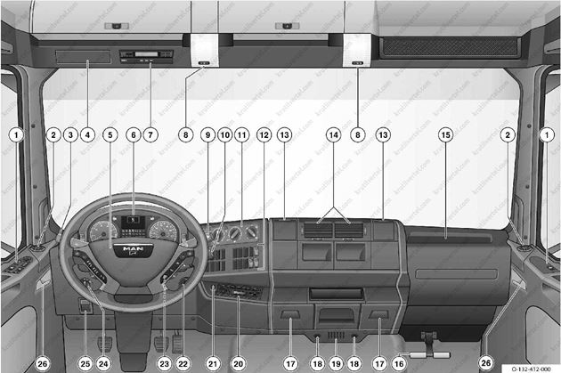
- Переключатели центрального замка, электрических стеклоподъемников, наружных зеркал заднего вида.
- Воздушное сопло у бокового стекла.
- Переключатель освещения, звукового сигнала, стеклоочистителей и омывателей.
- Ниша для дополнительного устройства, например электронной системы учета дорожных пошлин.
- Мультифункциональное рулевое колесо.
- Приборная панель.
- Контроллер ЕС (тахограф).
- Внутреннее освещение.
- Тормоз-замедлитель.
- Переключатель круиз-контроля и ограничения скорости/автоматическая коробка передач/тормоз-замедлитель.
- Система отопления, вентиляции и кондиционирования воздуха.
- Клавиши и выключатели.
- Подстаканник.
- Центральные воздушные дефлекторы.
- Блок предохранителей и реле.
- Подставка для ног.
- Пепельница.
- Розетки.
- Датчик температуры в кабине.
- Радиоприемник.
- Прикуриватель.
- Переключатель блокировки дифференциала.
- Замок зажигания.
- Переключатель стояночного и ближнего света.
- Ручка отпирания передней панели кабины.
- Ручка отпирания двери.
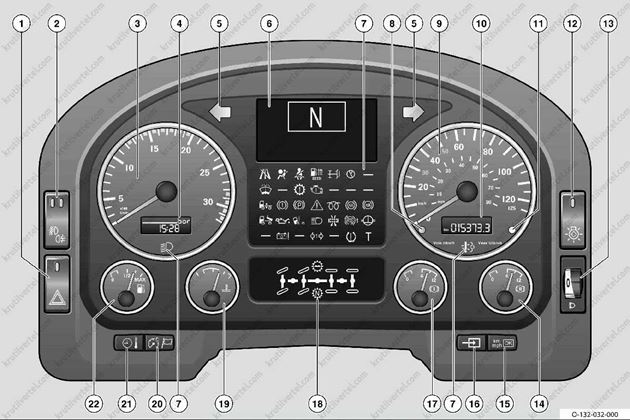
Приборная панель («Евро-2/3/4»)
- Выключатель аварийной световой сигнализации.
- Выключатель передних и задних противотуманных фар/фонарей.
- Тахометр.
- Экран времени и температуры снаружи/давления наддува/подсветки приборов.
- Индикаторы указателей поворота тягача.
- Дисплей.
- Контрольные индикаторы.
- Датчик автоматической регулировки яркости внутреннего освещения.
- Спидометр.
- Одометр/счетчик суточного пробега.
- Индикатор максимальной скорости.
- Выключатель светового теста.
- Регулятор угла наклона оптической оси фар.
- Указатель давления в тормозном контуре II.
- Кнопка подтверждения «желтых» сообщений на дисплее/изменения индикации «км/ч» или «миль/ч»/меню автомобиля (в автомобилях без мультифункционального рулевого колеса).
- Кнопка долговременной индикации на дисплее/переключения индикации при нескольких индикациях на дисплее/меню автомобиля (вавтомобилях без мультифункционального рулевого колеса).
- Указатель давления втормозном контуре I.
- Индикация блокировок дифференциалов.
- Указатель температуры охлаждающей жидкости.
- Кнопка подсветки приборов/выбора языка.
- Кнопка переключения индикации времени и температуры снаружи.
- Указатель уровня топлива.
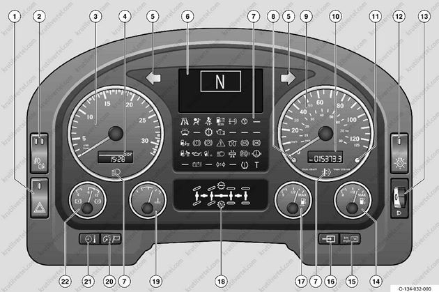
Приборная панель («Евро-5»)
- Выключатель аварийной световой сигнализации.
- Выключатель передних и задних противотуманных фар/фонарей.
- Тахометр.
- Экран времени и температуры снаружи/давления наддува/подсветки приборов.
- Индикаторы указателей поворота тягача.
- Дисплей.
- Контрольные индикаторы.
- Датчик автоматической регулировки яркости внутреннего освещения.
- Спидометр.
- Одометр/счетчик суточного пробега.
- Индикатор максимальной скорости.
- Выключатель светового теста.
- Регулятор угла наклона оптической оси фар.
- Указатель уровня топлива.
- Кнопка подтверждения «желтых» сообщений на дисплее/изменения индикации «км/ч» или «миль/ч»/меню автомобиля (в автомобилях без мультифункционального рулевого колеса).
- Кнопка долговременной индикации на дисплее/переключения индикации при нескольких индикациях на дисплее/меню автомобиля (вавтомобилях без мультифункционального рулевого колеса).
- Указатель уровня восстановителя AdBlue.
- Индикация блокировок дифференциалов.
- Указатель температуры охлаждающей жидкости.
- Кнопка подсветки приборов/выбора языка.
- Кнопка переключения индикации времени и температуры снаружи.
- Указатель давления в тормозном контуре I и II.
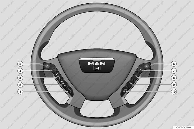
1—5. Кнопки меню автомобиля/автотелефона/аудиоустановки.
6—9. Кнопки системы круиз-контроля/частоты вращения двигателя на холостом ходу/вспомогательных агрегатов.
10. Кнопка системы круиз-контроля и ограничителя скорости.
Выключатели и кнопки
| Символ | Значение |
 |
Аварийная световая сигнализация |
 |
Стояночный свет |
 |
Ближний свет |
 |
Дальний свет |
 |
Задний противотуманный фонарь |
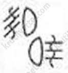 |
Противотуманная фара и задний противотуманный фонарь |
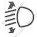 |
Регулирование угла наклона оптической оси фар |
 |
Световой тест |
 |
Система MAN BrakeMatic в автомобилях с нерегулируемым моторным тормозом |
 |
Система MAN BrakeMatic в автомобилях с регулируемым моторным тормозом, первичным замедлителем итрансмиссионным тормозом MAN |
 |
Переключение между ограничением скорости движения (FGB) и регулированием скорости (FGR) |
 |
Время/температура снаружи/обнуление времени |
 |
Подсветка приборов |
 |
Выбор языка |
 |
Изменение индикации на дисплее/закрытие долговременной индикации/использование меню автомобиля (вавтомобилях без мультифункционального рулевого колеса) |
 |
Подтверждение «желтого» сообщения/переключение индикации на спидометре между общим пробегом, суточным пробегом и индикацией фактической скорости в милях в час (миль/ч)/использование меню автомобиля (в автомобилях без мультифункционального рулевого колеса) |
 |
LGS, регулятор продольной устойчивости автомобиля |
 |
Подогрев сиденья |
 |
Подогрев и вентиляция сиденья |
 |
Приподнимание или разгрузка заднего поддерживающего моста |
 |
Приподнимание или разгрузка переднего поддерживающего моста |
 |
Система поддержки при трогании с места для заднего поддерживающего моста |
 |
Система поддержки при трогании с места для переднего поддерживающего моста |
 |
Задний поддерживающий мост прицепа или полуприцепа, система поддержки при трогании с места |
 |
Пневматическая подвеска |
 |
Переключение индикации запаса топлива между баками 1 и 2 |
 |
Ночная подсветка на потолке |
 |
Разъединитель аккумулятора |
 |
Аварийный выключатель |
 |
Противосолнечная шторка водителя и пассажира |
 |
Повышение порога пробуксовки |
 |
Повышение порога пробуксовки |
 |
Остановочный тормоз |
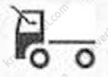 |
Сдвижная панель крыши |
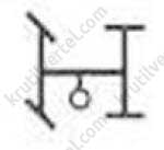 |
Коробка отбора мощности I |
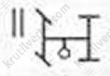 |
Коробка отбора мощности II |
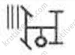 |
Коробка отбора мощности III |
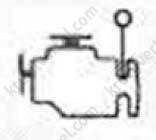 |
Коробка отбора мощности двигателя |
 |
Система охлаждения кузова прицепа |
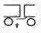 |
Система с низким сцеплением |
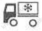 |
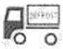
Система охлаждения грузового отсека тягача |
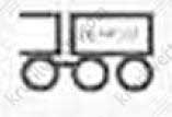 |
Система охлаждения грузового отсека прицепа дефростера |
 |
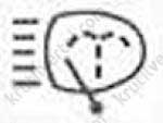
Система охлаждения грузового отсека тягача дефростера |
 |
Фароочиститель |
 |
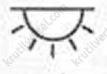
Фонарь рабочего освещения |
 |
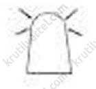
Освещение грузового отсека |
 |
Проблесковый маячок |
 |
Проблесковый маячок |
 |
Зимняя служба |
 |
Маневровое освещение |
 |
Дополнительный габаритный огонь для эксплуатации автомобиля с прицепом |
 |
Грузоподъемная платформа |
 |
Механизм опрокидывания кабины |
 |
Обогрев ветрового стекла |
 |
Централизованная смазочная система |
 |
Переключение между сигналом и гудком |
 |
Снижение громкости предупредительного сигнала заднего хода ночью, для снижения громкости звукового сигнала при движении задним ходом |
 |
Вызов техпомощи |
 |
Аккумулятор холода стационарного кондиционера |
 |
Стендовая обкатка двигателя («зимний пакет») |
 |
Стеклоподъемник водителя и пассажира |
 |
Холодильник |
 |
Дополнительный компрессор |
Контрольные индикаторы
| Символ | Значение |
 |
Центральная сигнальная лампочка |
 |
LGS, регулятор продольной устойчивости автомобиля |
 |
Подушка безопасности |
 |
Контроль ремня безопасности |
 |
Система подогрева топливного фильтра |
 |
Рулевое управление поддерживающего моста |
 |
Гидравлическая система |
 |
Стеклоомыватель |
 |
Коробка передач |
 |
Двигатель |
 |
ECAS, электронная пневматическая подвеска |
 |
Тормозная система |
 |
Стояночный тормоз |
 |
Электрофакельный пуск |
 |
ABS, антиблокировочная система |
 |
ASR, антипробуксовочная система |
 |
ESP, электронная система обеспечения устойчивости |
 |
Самосвал (см. руководство по эксплуатации производителя) |
 |
Грузоподъемная платформа |
 |
Давление моторного масла |
 |
Фиксация кабины |
 |
Ближний свет фар |
 |
Дальний свет фар |
 |
Воздушный фильтр |
 |
Информация по ABS прицепа |
 |
WSK, гидротрансформатор и сцепление |
 |
Ошибка аварийного отключения |
 |
Индикаторы указателей поворота тягача |
 |
Индикаторы указателей поворота прицепа |
 |
Система контроля давления в шинах (TPM) |
 |
Цифровой контроллер |
 |
Понижающая передача |
 |
Нейтральное положение раздаточной коробки |
 |
Контроль отработанных газов |
Индикация на тахометре и спидометре
Индикация на тахометре
Индикация времени или наружной температуры

![]()
MAN TGA Operator’s Manual
MAN TGA Operator’s Manual
MAN TGA Operator’s Manual.pdf
Adobe Acrobat Document
2.7 MB
![]()
MAN TGA Wiring Diagrams
MAN TGA Wiring Diagrams
MAN TGA Wiring Diagrams.pdf
Adobe Acrobat Document
1.7 MB

MAN TGA Truck Operator’s Manual & Electric Wiring Diagrams PDF are above the page.
The largest truck in the German company’s lineup, MAN TGA, is the benchmark for many manufacturers around the world.
MAN TGA heavy trucks replaced the popular F2000 series and immediately won many awards from journalists and
professionals in the field of cargo transportation, as a result of the assignment in the same year of the prestigious title of «Truck of The Year».
The MAN TGA range consists of truck tractors and chassis with a gross weight of 18 to 50 tons, depending on the curb weight, cars are 2-, 3- and 4-axle. So for trucks with curb
weight from 18 to 26 tons, trucks with one rear drive axle and one front steered axle are produced, it is also possible to install with two dual rear axles, one of which is the drive axle.
For tractors with a gross weight of more than 35 tons, three-axle versions with two or three steered axles are available.
Also, MAN TGA is made in the form of dump trucks with a wheel formula up to 8X8, these are exactly the cars used in the German army.
For variants with three axles, the wheelbase is from 2600 mm to 2800 mm, and for biaxial tractors, from 3500 mm to 3900 mm, respectively.
Engines — L6 from 310 to 530hp, and the flagship among the engines installed on the TGA, is the V10 engine with a volume of 18.3 liters with a power of 660 hp which complete only
a limited series of tractors.
Depending on the engine, two gearboxes are available — a 12-speed own production and a 16-speed ZF.
Trucks with several types of cabs leave the conveyor, each of which varies in size — LX, XLX and XXL, the last most comfortable cab has an internal height of 2.2 m.
The minimum internal height at the M cab is only 1.65 m, such a cab is offered only for trucks without a berth, whereas in XXL two beds can be installed.
Despite the fact that the MAN TGA has been replaced with the newer TGX model, thanks to the excellent price-quality ratio in many markets, this model is still
for sale.
Guidelines to fitting bodies
TRUCKNOLOGY® GENERATION A (TGA)
Edition 2011 Version 1.0
P U B L I S H E R
MAN Truck & Bus AG
(mentioned in the text below “MAN“)
ESC Department
Engineering Services
Consultation
D a c h a u e r S t r. 6 6 7
D — 8 0 9 9 5 M u n i c h
E-Mail: esc@man.eu
Fax:
+ 49 (0) 89 1580 4264
We reserve the right to make changes in the course of technical development.
© 2011 MAN Truck & Bus Aktiengesellschaft
Reprinting, reproduction or translation, even of excerpts, is not permitted without the written permission of MAN. All rights, in particular under copyright, are strictly reserved by MAN.
Trucknology® and MANTED® are registered trademarks of MAN Truck & Bus AG
Where designations are trademarks they are, even without the ® or ™ sign, acknowledged as the proprietor‘s protected marks.

TRUCKNOLOGY® GENERATION A (TGA)
|
1. |
Applicability and legal agreements |
1 |
||||||||||||||||||||||||||||||||
|
1.1 |
Applicability |
1 |
||||||||||||||||||||||||||||||||
|
1.2 |
Legal agreements and approval procedure |
1 |
||||||||||||||||||||||||||||||||
|
1.2.1 |
Preconditions |
1 |
||||||||||||||||||||||||||||||||
|
1.2.2 |
Responsibility |
2 |
||||||||||||||||||||||||||||||||
|
1.2.3 |
Quality assurance |
2 |
||||||||||||||||||||||||||||||||
|
1.2.4 |
Approval |
3 |
||||||||||||||||||||||||||||||||
|
1.2.5 |
Submission of documents |
3 |
||||||||||||||||||||||||||||||||
|
1.2.6 |
Liability for defects |
4 |
||||||||||||||||||||||||||||||||
|
1.2.7 |
Product liability |
5 |
||||||||||||||||||||||||||||||||
|
1.2.8 |
Safety |
5 |
||||||||||||||||||||||||||||||||
|
1.2.9 |
Manuals from body and conversion companies |
6 |
||||||||||||||||||||||||||||||||
|
1.2.10 |
Limitation of liability for accessories/spare parts |
7 |
||||||||||||||||||||||||||||||||
|
2. |
Product designations |
7 |
||||||||||||||||||||||||||||||||
|
2.1 |
Vehicle designation and wheel formula |
7 |
||||||||||||||||||||||||||||||||
|
2.1.1 |
Door designation |
7 |
||||||||||||||||||||||||||||||||
|
2.1.2 |
Variant descriptor |
7 |
||||||||||||||||||||||||||||||||
|
2.1.3 |
Wheel formula |
8 |
||||||||||||||||||||||||||||||||
|
2.1.4 |
Suffi x |
9 |
||||||||||||||||||||||||||||||||
|
2.2 |
Model number, vehicle identification number, vehicle number, basic vehicle number |
10 |
||||||||||||||||||||||||||||||||
|
2.3 |
Use of logos |
13 |
||||||||||||||||||||||||||||||||
|
2.4 |
Cabs |
14 |
||||||||||||||||||||||||||||||||
|
2.5 |
Engine variants |
16 |
||||||||||||||||||||||||||||||||
|
3. |
General |
17 |
||||||||||||||||||||||||||||||||
|
3.1 |
Axle overload, one-sided loading |
17 |
||||||||||||||||||||||||||||||||
|
3.2 |
Minimum front axle load |
19 |
||||||||||||||||||||||||||||||||
|
3.3 |
Wheels, rolling circumference |
20 |
||||||||||||||||||||||||||||||||
|
3.4 |
Permissible overhang |
20 |
||||||||||||||||||||||||||||||||
|
3.5 |
Theoretical wheelbase, overhang, theoretical axle centreline |
21 |
||||||||||||||||||||||||||||||||
|
3.6 |
Calculating the axle load and weighing procedure |
23 |
||||||||||||||||||||||||||||||||
|
3.7 |
Checking and adjustment procedures once body has been fi tted |
24 |
||||||||||||||||||||||||||||||||
|
3.8 |
Notes on MAN Hydrodrive® |
25 |
||||||||||||||||||||||||||||||||
|
TRUCKNOLOGY® GENERATION A (TGA) |
I |

|
4. |
Modifying the chassis |
25 |
|||||||||||||||||||||||||||||||||||||||||
|
4.1 |
Frame material |
25 |
|||||||||||||||||||||||||||||||||||||||||
|
4.2 |
Corrosion protection |
30 |
|||||||||||||||||||||||||||||||||||||||||
|
4.3 |
Drill holes, riveted joints and screw connections on the frame |
30 |
|||||||||||||||||||||||||||||||||||||||||
|
4.4 |
Modifying the frame |
33 |
|||||||||||||||||||||||||||||||||||||||||
|
4.4.1 |
Welding the frame |
33 |
|||||||||||||||||||||||||||||||||||||||||
|
4.4.2 |
Modifying the frame overhang |
35 |
|||||||||||||||||||||||||||||||||||||||||
|
4.4.3 |
Modifi cations to the wheelbase |
37 |
|||||||||||||||||||||||||||||||||||||||||
|
4.5 |
Retrofi tting additional equipment add-on components or accessories |
43 |
|||||||||||||||||||||||||||||||||||||||||
|
4.5.1 |
Retrofi tting additional or larger fuel tanks after factory delivery |
44 |
|||||||||||||||||||||||||||||||||||||||||
|
4.6 |
Propshafts |
45 |
|||||||||||||||||||||||||||||||||||||||||
|
4.6.1 |
Single joint |
45 |
|||||||||||||||||||||||||||||||||||||||||
|
4.6.2 |
Jointed shaft with two joints |
46 |
|||||||||||||||||||||||||||||||||||||||||
|
4.6.3 |
Three-dimensional propshaft layout |
47 |
|||||||||||||||||||||||||||||||||||||||||
|
4.6.3.1 Propshaft train |
48 |
||||||||||||||||||||||||||||||||||||||||||
|
4.6.3.2 Forces in the propshaft system |
48 |
||||||||||||||||||||||||||||||||||||||||||
|
4.6.4 |
Modifying the propshaft layout in the driveline of MAN chassis |
49 |
|||||||||||||||||||||||||||||||||||||||||
|
4.7 |
Modifying the wheel formula |
49 |
|||||||||||||||||||||||||||||||||||||||||
|
4.8 |
Coupling devices |
51 |
|||||||||||||||||||||||||||||||||||||||||
|
4.8.1 |
Basics |
51 |
|||||||||||||||||||||||||||||||||||||||||
|
4.8.2 |
Trailer coupling, D value |
52 |
|||||||||||||||||||||||||||||||||||||||||
|
4.9 |
Tractor units and converting the vehicle type — truck / tractor |
52 |
|||||||||||||||||||||||||||||||||||||||||
|
4.9.1 |
Articulated vehicles |
52 |
|||||||||||||||||||||||||||||||||||||||||
|
4.9.2 |
Converting trucks into tractor units or tractor units into trucks |
55 |
|||||||||||||||||||||||||||||||||||||||||
|
4.10 |
Modifying the cab |
55 |
|||||||||||||||||||||||||||||||||||||||||
|
4.10.1 |
General |
55 |
|||||||||||||||||||||||||||||||||||||||||
|
4.10.2 |
Spoilers, roof extensions, roofwalk |
55 |
|||||||||||||||||||||||||||||||||||||||||
|
4.10.3 |
Roof sleeper cabs |
58 |
|||||||||||||||||||||||||||||||||||||||||
|
4.11 |
Add-on frame components |
59 |
|||||||||||||||||||||||||||||||||||||||||
|
4.11.1 |
Rear underride guard |
59 |
|||||||||||||||||||||||||||||||||||||||||
|
4.11.2 |
FUP — front underride protection |
61 |
|||||||||||||||||||||||||||||||||||||||||
|
4.11.3 |
Sideguards |
62 |
|||||||||||||||||||||||||||||||||||||||||
|
4.12 |
Modifi cations to engine systems |
64 |
|||||||||||||||||||||||||||||||||||||||||
|
4.12.1 |
Modifi cations to the air intake and exhaust gas routing for engines up to and |
64 |
|||||||||||||||||||||||||||||||||||||||||
|
including Euro4 with On Board Diagnosis |
64 |
||||||||||||||||||||||||||||||||||||||||||
|
4.12.2 |
Additional requirements if changes are made to the AdBlue® system/exhaust |
66 |
|||||||||||||||||||||||||||||||||||||||||
|
system on Euro5 vehicles |
66 |
||||||||||||||||||||||||||||||||||||||||||
|
4.12.3 |
Engine cooling |
74 |
|||||||||||||||||||||||||||||||||||||||||
|
4.12.4 |
Engine encapsulation, noise insulation |
74 |
|||||||||||||||||||||||||||||||||||||||||
|
4.13 |
Fitting other manual gearboxes, automatic transmissions and transfer boxes |
74 |
|||||||||||||||||||||||||||||||||||||||||
|
TRUCKNOLOGY® GENERATION A (TGA) |
II |

|
5. |
Bodies |
74 |
|||||||||||||||||||||||||||
|
5.1 |
General |
74 |
|||||||||||||||||||||||||||
|
5.2 |
Corrosion protection |
76 |
|||||||||||||||||||||||||||
|
5.3 |
Subframes |
76 |
|||||||||||||||||||||||||||
|
5.3.1 |
General |
76 |
|||||||||||||||||||||||||||
|
5.3.2 |
Permissible materials, yield points |
77 |
|||||||||||||||||||||||||||
|
5.3.3 |
Subframe design |
79 |
|||||||||||||||||||||||||||
|
5.3.4 |
Attaching subframes and bodies |
80 |
|||||||||||||||||||||||||||
|
5.3.5 |
Screw connections and riveted joints |
81 |
|||||||||||||||||||||||||||
|
5.3.6 |
Flexible connection |
84 |
|||||||||||||||||||||||||||
|
5.3.7 |
Rigid connection |
87 |
|||||||||||||||||||||||||||
|
5.4 |
Bodies |
87 |
|||||||||||||||||||||||||||
|
5.4.1 |
Testing of bodies |
87 |
|||||||||||||||||||||||||||
|
5.4.2 |
Platform and box bodies |
88 |
|||||||||||||||||||||||||||
|
5.4.3 |
Tail-lifts |
96 |
|||||||||||||||||||||||||||
|
5.4.4 |
Interchangeable containers |
97 |
|||||||||||||||||||||||||||
|
5.4.5 |
Self-supporting bodies without subframe |
98 |
|||||||||||||||||||||||||||
|
5.4.6 |
Single-pivot body |
98 |
|||||||||||||||||||||||||||
|
5.4.7 |
Tank and container bodies |
101 |
|||||||||||||||||||||||||||
|
5.4.8 |
Tippers |
103 |
|||||||||||||||||||||||||||
|
5.4.9 |
Set-down, sliding set-down and sliding roll-off tippers |
104 |
|||||||||||||||||||||||||||
|
5.4.10 |
Propping air-sprung vehicles |
105 |
|||||||||||||||||||||||||||
|
5.4.11 |
Loading cranes |
106 |
|||||||||||||||||||||||||||
|
5.4.12 |
Cable winches |
116 |
|||||||||||||||||||||||||||
|
5.4.13 |
Transport mixers |
116 |
|||||||||||||||||||||||||||
|
5.4.14 |
Car transporter |
117 |
|
TRUCKNOLOGY® GENERATION A (TGA) |
III |

|
6. |
Electrics, electronics, wiring |
118 |
|||||||||||||||||||||
|
6.1 |
General |
118 |
|||||||||||||||||||||
|
6.2 |
Routing cables, earth cable |
118 |
|||||||||||||||||||||
|
6.3 |
Handling batteries |
118 |
|||||||||||||||||||||
|
6.3.1 |
Handling and maintaining the batteries |
118 |
|||||||||||||||||||||
|
6.3.2 |
Handling and maintaining batteries with PAG technology |
119 |
|||||||||||||||||||||
|
6.4 |
Additional wiring diagrams and wiring harness drawings |
120 |
|||||||||||||||||||||
|
6.5 |
Fuses, additional power consumers |
120 |
|||||||||||||||||||||
|
6.6 |
Lighting installations |
123 |
|||||||||||||||||||||
|
6.7 |
Electromagnetic compatibility |
123 |
|||||||||||||||||||||
|
6.8 |
Radio equipment and aerials |
124 |
|||||||||||||||||||||
|
6.9 |
Interfaces on the vehicle, preparations for the body |
126 |
|||||||||||||||||||||
|
6.9.1 |
Electrical connections for tail-lifts |
126 |
|||||||||||||||||||||
|
6.9.2 |
Start-stop control on frame end |
126 |
|||||||||||||||||||||
|
6.10 |
Electronics |
127 |
|||||||||||||||||||||
|
6.10.1 |
Display and instrumentation concept |
127 |
|||||||||||||||||||||
|
6.10.2 |
Diagnostics concept and parameterisation using MAN-cats® |
127 |
|||||||||||||||||||||
|
6.10.3 |
Parameterisation of the vehicle electronics |
127 |
|
TRUCKNOLOGY® GENERATION A (TGA) |
IV |

|
7. |
Power take-off |
(See separate booklet) |
127 |
|||||||||||||||||||||||||||||||
|
8. |
Brakes, lines |
128 |
||||||||||||||||||||||||||||||||
|
8.1 |
ALB, EBS braking system |
128 |
||||||||||||||||||||||||||||||||
|
8.2 |
Brake and compressed air lines |
128 |
||||||||||||||||||||||||||||||||
|
8.2.1 |
Basic principles |
128 |
||||||||||||||||||||||||||||||||
|
8.2.2 |
Voss 232 system plug connectors |
129 |
||||||||||||||||||||||||||||||||
|
8.2.3 |
Installing and attaching lines |
130 |
||||||||||||||||||||||||||||||||
|
8.2.4 |
Compressed air loss |
132 |
||||||||||||||||||||||||||||||||
|
8.3 |
Connecting additional air consumers |
132 |
||||||||||||||||||||||||||||||||
|
8.4 |
Retrofi tting continuous brakes not manufactured by MAN |
134 |
||||||||||||||||||||||||||||||||
|
9. |
Calculations |
134 |
||||||||||||||||||||||||||||||||
|
9.1 |
Speed |
134 |
||||||||||||||||||||||||||||||||
|
9.2 |
Effi ciency |
135 |
||||||||||||||||||||||||||||||||
|
9.3 |
Tractive force |
136 |
||||||||||||||||||||||||||||||||
|
9.4 |
Gradeability |
137 |
||||||||||||||||||||||||||||||||
|
9.4.1 |
Distance travelled on uphill or downhill gradients |
137 |
||||||||||||||||||||||||||||||||
|
9.4.2 |
Angle of uphill or downhill gradient |
137 |
||||||||||||||||||||||||||||||||
|
9.4.3 |
Calculating the gradeability |
138 |
||||||||||||||||||||||||||||||||
|
9.5 |
Torque |
142 |
||||||||||||||||||||||||||||||||
|
9.6 |
Power output |
143 |
||||||||||||||||||||||||||||||||
|
9.7 |
Rotational speeds for power take-offs at the transfer case |
145 |
||||||||||||||||||||||||||||||||
|
9.8 |
Driving resistances |
146 |
||||||||||||||||||||||||||||||||
|
9.9 |
Turning circle |
149 |
||||||||||||||||||||||||||||||||
|
9.10 |
Axle load calculation |
151 |
||||||||||||||||||||||||||||||||
|
9.10.1 |
Performing an axle load calculation |
151 |
||||||||||||||||||||||||||||||||
|
9.10.2 |
Calculation of weight with trailing axle lifted |
154 |
||||||||||||||||||||||||||||||||
|
9.11 |
Support length for bodies without subframes |
156 |
||||||||||||||||||||||||||||||||
|
9.12 |
Coupling devices |
157 |
||||||||||||||||||||||||||||||||
|
9.12.1 |
Trailer coupling |
157 |
||||||||||||||||||||||||||||||||
|
9.12.2 |
Rigid drawbar trailers / central axle trailers |
157 |
||||||||||||||||||||||||||||||||
|
9.12.3 |
Fifth-wheel coupling |
159 |
The ESC numbers stated in the illustrations are purely for internal reference.
They are of no consequence to the reader.
If not otherwise stated: all dimensions in mm, all weights and loads in kg
|
TRUCKNOLOGY® GENERATION A (TGA) |
V |

1.Applicability and legal agreements
1.1Applicability
The statements in this guide are binding. If technically feasible, exceptions will be approved only if a written request has been submitted to the ESC department at MAN, (see „Publisher“ above).
1.2Legal agreements and approval procedure
1.2.1Preconditions
In addition to this Guide, the company carrying out the work must observe all
•laws and decrees
•accident prevention regulations
•operating instructions
relating to the operation and construction of the vehicle. Standards are technical standards; they are therefore minimum requirements. Anyone who does not endeavour to observe these minimum requirements is regarded as operating negligently.
Standards are binding when they form part of regulations.
Information given by MAN in reply to telephone enquiries is not binding unless confi rmed in writing. Enquiries are to be directed to
the relevant MAN department. Information refers to conditions of use that are usual within Europe. Dimensions, weights and other basic data that differ from these must be taken into consideration when designing the body, mounting the body and designing the subframe. The company carrying out the work must ensure that the entire vehicle can withstand the conditions of use that it is expected
to experience.
For certain types of equipment, such as loading cranes, tail-lifts, cable winches etc, the respective manufacturers have developed their own body regulations. If, when compared with this MAN Guide, they impose further conditions, then these too must be observed.
References to
•legal stipulations
•accident prevention regulations
•decrees from professional associations
•work regulations
•other guidelines and sources of information
are not in any way complete and are only intended as ideas for further information. They do not replace the company’s obligation to carry out its own checks.
Fuel consumption is considerably affected by modifi cations to the vehicle, by the body and its design and by the operation of equipment driven by the vehicle’s engine. It is therefore expected that the company carrying out the work implements a design that facilitates
the lowest possible fuel consumption.
|
TRUCKNOLOGY® GENERATION A (TGA) |
1 |

1.2.2Responsibility
The responsibility for proper
•design
•production
•installation of bodies
•modifi cation to the chassis
always lies fully with the company that is manufacturing the body, installing it or carrying out modifi cations (manufacturer’s liability). This also applies if MAN has expressly approved the body or the modifi cation. Bodies/conversions that have been approved in writing by MAN do not release the body manufacturer from his responsibility for the product. Should the company carrying out the work detect a mistake either in the planning stage or in the intentions of
•the customer
•the user
•its own personnel
•the vehicle manufacturer
then that mistake must be brought to the attention of the respective party.
The company is responsible for seeing that the vehicle’s
•operational safety
•traffi c safety
•maintenance possibilities and
•handling characteristics
do not exhibit any disadvantageous properties.
With regard to traffi c safety, the company must operate in accordance with the state of the art and in line with the recognised rules in the fi eld in matters relating to
•the design
•the production of bodies
•the installation of bodies
•the modifi cation of chassis
•instructions and
•operating instructions.
Diffi cult conditions of use must also be taken into account.
1.2.3Quality assurance
In order to meet our customers’ high quality expectations and in view of international product/manufacturer liability legislation an on-going quality monitoring programme is also required for conversions and body manufacture/installation. This requires a functioning quality assurance system. It is recommended that the body manufacturer sets up and provides evidence of a quality system that complies with the general requirements and recognised rules (e.g. DIN EN ISO 9000 et seq. or VDA 8).
Evidence of a qualifi ed system can be provided for example by:
|
TRUCKNOLOGY® GENERATION A (TGA) |
2 |

If MAN is the party awarding the contract for the body or conversion evidence of qualifi cation will be requested.
MAN Truck & Bus AG reserves the right to carry out its own system audit in accordance with VDA 8 or a corresponding process check at the supplier’s premises. VDA volume 8 has been agreed with the following body manufacturers’ associations:
ZKF (Zentralverband Karosserieund Fahrzeugtechnik – Central Association of Body and Vehicle Engineering) and
BVM (Bundesverband Metall Vereinigung Deutscher Metallhandwerke – Federation of German Metal Trades Associations).
It has also been agreed with the ZDH (Zentralverband des Deutschen Handwerks – Central Association of German Craft Trades).
Documents:
VDA Volume 8
„Minimum quality assurance requirements for trailer, body manufacturers“, obtainable from the Verband der Automobilindustrie e.V (VDA) (German Engine Industry Association), http://www.vda-qmc.de.
1.2.4Approval
Approval from MAN for a body or a chassis modifi cation is not required if the bodies or modifi cations are carried out in accordance with this Guide. If MAN approves a body or a chassis modifi cation, then this approval refers
•In the case of bodies only to the body’s fundamental compatibility with the respective chassis and the interfaces to the body (e.g. dimensions and mounting of the subframe)
•In the case of chassis modifi cations only to the fact that, from a design point of view, the modifi cations to the chassis in question are fundamentally permissible.
The approval note that MAN enters on the submitted technical documents does not indicate a check on the
•Function
•Design
•Equipment of the body or the modifi cation.
Observance of this Guide does not free the user from responsibility to perform modifi cations and manufacture bodies properly from
a technical point of view. The approval note only refers to such measures or components as are to be found in the submitted technical documents.
MAN reserves the right to refuse to issue approvals for bodies or modifi cations, even if a comparable approval has already been issued. Later submissions for approval are not automatically treated the same as earlier ones, because technical advances achieved in
the interim period have to be taken into account.
MAN also reserves the right to change this Guide at any time or to issue instructions that differ from this Guide for individual chassis.
If several identical chassis have the same bodies or modifi cations MAN can, to simplify matters, issue a collective approval.
1.2.5Submission of documents
Documents should only be sent to MAN if bodies/conversions diverge from this Guide. Before work begins on the vehicle, technical documents that require approval or inspection must be sent to the ESC Department at MAN (see „Publisher“ above).
For an approval process to proceed swiftly, the following are required:
•Documents should be submitted in duplicate
•The number of individual documents should be kept to a minimum
•All the technical data and documents must be submitted.
|
TRUCKNOLOGY® GENERATION A (TGA) |
3 |

The following information should be included:
•Vehicle model (see Chapter 2.2 for model code) with
—cab design
—wheelbase
—frame overhang
•· Vehicle identifi cation number or vehicle number (if already available, see Chapter 2.2)
Identifi cation of deviations from this Guide to Fitting Bodies in all documentation!
•Loads and their load application points:
—Forces from the body
—Axle load calculation
•Special conditions of use:
•Subframe:
—Material and cross-sectional data
—Dimensions
—Type of section
—Arrangement of cross members in the subframe
—Special features of the subframe design
—Cross-section modifi cations
—Additional reinforcements
—Upsweeps, etc.
•Means of connection:
—Positioning (in relation to the chassis)
—Type
—Size
—Number.
The following are not suffi cient for inspection or approval:
•Parts lists
•Brochures
•Photographs
•Other not binding information.
Drawings are only valid if they bear the number that has been assigned to them. It is therefore not permitted to draw in the bodies or modifi cations on chassis drawings that have been provided by MAN and to submit these for approval.
1.2.6Liability for defects
Liability claims in respect of defects only exist within the framework of the purchasing contract between buyer and seller. In accordance with this, liability for defects lies with the respective seller of the goods.
Claims against MAN are not valid if the fault that is the subject of the complaint was due to the fact that
•This Guide was not observed
•In view of the purpose for which the vehicle is used, an unsuitable chassis has been selected
•The damage to the chassis has been caused by
—the body
—the type of body mounting or how the body has been mounted
—the modifi cation to the chassis
—improper use.
|
TRUCKNOLOGY® GENERATION A (TGA) |
4 |

1.2.7Product liability
Any faults in the work that are identifi ed by MAN are to be corrected. Insofar as is legally permissible, MAN disclaims all liability, in particular for consequential damage.
Product liability regulates:
•The liability of the manufacturer for its product or component
•The compensation claim made by the manufacturer against whom a claim has been made against the manufacturer of an integral component, if the damage that has occurred is due to a fault in that component.
The company that has made the body or carried out the modifi cation is to relieve MAN of any liability to its customer or other third party if the damage that has occurred is due to the fact that
•The company did not observe this Guide
•The body or chassis modifi cation has caused damage on account of its faulty
—design
—manufacture
—installation
—instructions
•The fundamental rules that are laid down have not been complied with in any other way.
1.2.8Safety
Companies carrying out work on the chassis/vehicle are liable for any damage that may be caused by poor functional and operational safety or inadequate operating instructions. Therefore, MAN requires the body manufacturer or vehicle conversion company to:
•Ensure the highest possible safety, in line with the state of the art
•Provide comprehensible, suffi cient operating instructions
•Provide permanent, easily visible instruction plates on hazardous points for operators and/or third parties
•Observe the necessary protection measures (e.g. fi re and explosion prevention)
•Provide full toxicological information
•Provide full environmental information.
Safety is top priority! All available technical means of avoiding incidents that will undermine operational safety are to be implemented. This applies equally to
•Active safety = prevention of accidents. This includes:
—Driving safety achieved by the overall vehicle design, including the body
—Safety as a consequence of the driver’s well-being achieved by keeping occupant stress caused by vibrations, noise, climatic conditions etc. to a minimum
—Safety as a consequence of observation and perception, in particular through the correct design of lighting systems, warning equipment, providing suffi cient direct and indirect visibility
—Safety as a consequence of operating equipment and controls this includes optimising the ease of operation of all equipment, including that of the body.
•Passive safety = avoidance and reduction of the consequences of accidents. This includes:
—Exterior safety such as the design of the outside of the vehicle and body with respect to deformation behaviour and the installation of protective devices
—Interior safety including the protection of occupants of vehicles and cabs that are installed by the body builders.
|
TRUCKNOLOGY® GENERATION A (TGA) |
5 |

Climatic and environmental conditions have effects on:
•Operational safety
•Readiness for use
•Operational performance
•Service life
•Cost-effectiveness.
Climatic and environmental conditions are, for example:
•The effects of temperature
•Humidity
•Aggressive substances
•Sand and dust
•Radiation.
Suffi cient space for all parts required to carry out a movement, including all pipes and cables, must be guaranteed. The operating instructions for MAN trucks provide information about the maintenance points on the vehicle. Regardless of what type of body is fi tted, good access to the maintenance points must be ensured in all cases. It must be possible to carry out maintenance unhindered and without having to remove any components. Suffi cient ventilation and/or cooling of the components is to be guaranteed.
1.2.9Manuals from body and conversion companies
In the event of a body being added or modifi cations to the vehicle being carried out, the operator of the vehicle is also entitled to receive operating instructions from the conversion company. All specifi c advantages offered by the product are of no use if the customer is
not able to:
•Handle the product safely and properly
•Use it rationally and effortlessly
•Maintain it properly
•Master all of its functions.
As a result, every vehicle body builder and converter must check his technical instructions for:
•Clarity
•Completeness
•Accuracy
•Comprehensibility
•Product-specifi c safety instructions.
Inadequate or incomplete operating instructions carry considerable risks for the user. Possible effects are:
•Reduced benefi t, because the advantages of the product remain unknown
•Complaints and annoyance
•Faults and damage, which are normally blamed on the chassis
•Unexpected and unnecessary additional cost through repairs and time lost
•A negative image and thereby less inclination to buy the same product or brand again.
Depending on the vehicle body or modifi cation, the operating personnel must be instructed about operation and maintenance. Such instruction must also include the possible effects on the static and dynamic performance of the vehicle.
|
TRUCKNOLOGY® GENERATION A (TGA) |
6 |

1.2.10Limitation of liability for accessories/spare parts
Accessories and spare parts that MAN has not manufactured or approved for use in its products may affect the traffi c safety and operational safety of the vehicle and create hazardous situations. MAN Truck & Bus AG (or the seller) accepts
no liability for claims of any kind resulting from a combination of the vehicle together with an accessory that was made by another manufacturer, regardless of whether MAN Truck & Bus AG (or the seller) has sold the accessory itself or fi tted it to the vehicle (or the subject of the contract).
2.Product designations
2.1Vehicle designation and wheel formula
To enable unique and easily comprehensible identification of the different variants new vehicle designations have been systematically introduced. The vehicle designation system is based on three levels:
—Door designation
—Variant descriptor (in the sales and technical documentation e.g. data sheets, chassis drawings)
—Model code.
2.1.1Door designation
The door designation comprises:
Model range + permissible weight + engine power
TGA 18.400
|
Model range |
+ Permissible weight |
+ Engine power |
|
T G A |
1 8 |
. 4 0 0 |
Abbreviated notation of model range TGA = Trucknology® Generation A, technically permissible weight in [t],
engine power [DIN-hp] rounded to the nearest 10hp
2.1.2Variant descriptor
The variant descriptor = vehicle designation which comprises the door designation + wheel formula + suffi x. The terms ‘wheel formula’ and ‘suffi x’ are defi ned in the following sections.
Model range + permissible weight + engine power + wheel formula + suffi x
TGA 25.480 6×2-2 LL-U
|
Model range |
+ Permissible weight |
+ Engine power |
|
T G A |
2 5 |
. 4 8 0 |
6 x 2 — 2 |
L L — U |
|
Wheel formula |
Suffi x |
|
TRUCKNOLOGY® GENERATION A (TGA) |
7 |

2.1.3Wheel formula
The wheel formula stipulates the number of axles and provides additional identifi cation of drive, steered and leading/trailing axles. Wheel formula is a commonly used, but not standardised term. It is “wheel locations” that are counted and not the individual wheels. Twin tyres are therefore regarded as one wheel.
The following two examples illustrate the wheel formula:
Table 1: Wheel formula examples
6 x 2 — 4
6 x 2 / 4
6= Total number of wheel locations, i.e. 3 axles x = No function
2= Number of driven wheels
—= Trailing axle behind the rear drive-axle assembly
/= Leading axle ahead of the rear drive-axle assembly
4= Number of steered wheels
The number of steered wheels is only stated if, aside from steered front wheels, leading axles or trailing axles are also involved. A leading axle is located “ahead of” a rear drive-axle assembly and a trailing axle is “behind” the rear drive-axle assembly.
A slash “/” represents a leading axle and a hyphen “-” represents a trailing axle.
If a chassis is fi tted with both leading and trailing axles the number of steered wheels follows the hyphen “-”.
If the vehicle is fi tted with MAN HydroDrive® hydrostatic front axle drive then the wheel formula receives an additional H, e.g. 6x4H = a front axle with MAN HydroDrive®, 2 rear axles, one of which is driven.
Currently the following wheel formulae are available ex-works:
Table 2: TGA wheel formulae
4×2 Two-axle vehicle with one drive axle
4×4 Two-axle vehicle with two drive axles “All-wheel drive”
4x4H Two-axle vehicle with two drive axles, front axle with MAN HydroDrive®
6×2/2 Three-axle vehicle with non-steered “Pusher” leading axle
6×2/4 Three-axle vehicle with steered leading axle
6×2-2 Three-axle vehicle with non-steered trailing axle
6×2-4 Three-axle vehicle with steered trailing axle
6×4 Three-axle vehicle with two driven non-steered rear axles
6×4/4 Three-axle vehicle with 2 driven axles (fi rst and last axles), steered leading axle
6×4-4 Three-axle vehicle with 2 driven axles, (fi rst and second axles), steered trailing axle
6x4H/2 Three-axle vehicle with MAN HydroDrive® front axle drive, one driven rear axle, non-steered leading axle
6x4H/4 Three-axle vehicle with MAN HydroDrive® front axle drive, one driven rear axle, steered leading axle
6x4H-2 Three-axle vehicle with MAN HydroDrive® front axle drive, one driven rear axle, non-steered trailing axle
6x4H-4 Three-axle vehicle with MAN HydroDrive® front axle drive, one driven rear axle, steered trailing axle
|
TRUCKNOLOGY® GENERATION A (TGA) |
8 |

Table 2: TGA wheel formulae (continuation)
6×6 Three-axle vehicle with all-wheel drive
6×6-4 Three-axle vehicle with all-wheel drive, steered and driven trailing axle
6x6H Three-axle vehicle with all-wheel drive, front axle with MAN HydroDrive®
8×2-4 Four-axle vehicle with one drive axle, two steered front axles, non steered trailing axle or four-axle vehicle with three rear axles with front and trailing axles steered
8×2-6 Four-axle vehicle with one drive axle, two steered front axles, steered trailing axle
8×4 Four-axle vehicle with two steered front axles and two driven rear axles
8×4/4 Four-axle vehicle with one front axle, one steered leading axle and two driven rear axles
8×4-4 Four-axle vehicle with one front axle, two driven rear axles and one steered trailing axle
8x4H-4 Four-axle vehicle with two steered front axles (2nd front axle with MAN HydroDrive®), one driven rear axle and a non-steered trailing axle
8x4H-6 Four-axle vehicle with two steered front axles (2nd front axle with MAN HydroDrive®), one driven rear axle and a steered trailing axle
8×6 Four-axle vehicle “All wheel drive” with two front axles (2nd driven) and two driven rear axles
8x6H Four-axle vehicle “All wheel drive” with two front axles (2nd front axle with MAN HydroDrive®) and two driven rear axles
8×8 Four-axle vehicle “All wheel drive” with two front axles and two rear axles, all driven
2.1.4Suffix
The suffi x to the vehicle designation defi nes the type of suspension, differentiates trucks from tractor units and describes special product features.
|
T G A 2 5 . 4 8 0 6 x 2 — 2 |
LL-U |
|
|
Suffi x |
||
|
Types of suspension (Digits 1 and 2 of suffi x) |
||
|
Table 3: |
Types of suspension |
|
|
BB |
Leaf suspension on front axle(s), leaf suspension on rear axle(s) |
|
|
BL |
Leaf suspension on front axle(s), air suspension on rear axle(s) |
|
|
LL |
Air suspension on front axle(s), air suspension on rear axle(s) |
|
|
BH |
Leaf suspension on front axle(s), hydropneumatic on rear axle(s) |
Semitrailer tractor units are designated with an ‘S’ suffi x. Trucks have no special designation.
Example for semitrailer tractor:
|
T G A 3 3 . 4 4 0 6 x 6 |
BBS |
|
S = Semitrailer tractor |
|
|
TRUCKNOLOGY® GENERATION A (TGA) |
9 |

Special product (design) features are added separately following a hyphen ‘-’ after the fi rst section of the suffi x:
Example for special product features:
|
T G A 1 8 . 3 5 0 4 x 2 B L S |
-TS |
|
|
-TS = Weight optimised version for silo tanker |
||
|
Table 4: |
Designations for special designs produced to-date (to be supplemented with further designs) |
|
|
-U |
For low design ‘Ultra’ e.g.: TGA 18.410 4×2 LLS-U |
|
|
-TS |
Weight optimised version for silo tanker, e.g.: TGA 18.400 4×2 BLS-TS |
|
|
-WW |
“World wide” variant, eligible for licensing outside Europe only, e.g. TGA 40.460 6×6 BB-WW |
|
|
-LE |
“Low entry” cab with lowered entry, e.g.: TGA 28.310 6×2-4 LL-LE |
|
|
-CKD |
“Completely knocked down”, for assembly in MAN factory of the recipient country, e.g.: TGA 40.480 6×4-4 WW-CKD |
2.2Model number, vehicle identification number, vehicle number, basic vehicle number
The three-digit model number, also called model code, provides a technical identifi cation of the MAN chassis and also identifi es
to which vehicle range it belongs. This number is part of the 17-digit vehicle identifi cation number (VIN) and is located at digits 4 to 6 in the VIN. The basic vehicle number, formulated for sales purposes, also contains the model number at digits 2 to 4.
The seven-fi gure vehicle number describes the technical equipment on a vehicle; it contains the model number at digits 1 to 3, followed by a four-digit sequential number. The vehicle number is to be found in the vehicle papers and on the vehicle’s manufacturing plate. The vehicle number can be quoted instead of the 17-digit vehicle identifi cation number in the event of any technical queries regarding conversions and bodies. Table 5 gives some examples of the model number, vehicle identifi cation number, basic vehicle number and vehicle number.
Table 5: Example vehicle designation, model number, vehicle identifi cation number, basic vehicle number and vehicle number
|
Vehicle designation |
Model number |
Vehicle identifi cation number |
Basic vehicle |
Vehicle number |
|
Model code |
(VIN) |
number |
||
|
TGA 18.440 4×2 BLS |
H06 |
WMAH06ZZ14M000479 |
LH06AG53 |
H060057 |
|
TGA 26.410 6×2-4 LL |
H21 |
WMAH21ZZ94G144924 |
LH21E 05 |
H210058 |
|
TGA 33.540 6×4 BB |
H26 |
WMAH26ZZ75M350354 |
LH26LR04 |
H261158 |
Up to the date of going to press (03/2007) the Trucknology® Generation A or TGA for short, comprises the following model numbers:
|
TRUCKNOLOGY® GENERATION A (TGA) |
10 |

Table 6: Model numbers, tonnage class, vehicle designation and suspension on the TGA
|
Model number |
Tonnage |
Designation , xxx stands for |
Engine |
Suspension |
|
various engine powers |
||||
|
H01 |
18 t |
TGA 18.xxx 4×2 BLS-TS |
D28 R6 |
BL |
|
H02 |
18 t |
TGA 18.xxx 4×2 BB |
D28 R6 |
BB |
|
H03 |
18 t |
TGA 18.xxx 4×2 BB |
D20/D26 R6 |
BB |
|
H05 |
18 t |
TGA 18.xxx 4×2 BL |
D28 R6 |
BL |
|
H06 |
18 t |
TGA 18.xxx 4×2 BL |
D20/D26 R6 |
BL |
|
H07 |
18 t |
ECT 18.ISM 4×2 BL |
ISMe |
BL |
|
H08 |
18 t |
TGA 18.xxx 4×2 BLS-TS |
D20/D26 R6 |
BL |
|
H09 |
18 t |
TGA 18.xxx 4×2 LL |
D28 R6 |
LL |
|
H10 |
18 t |
TGA 18.xxx 4×2 LL |
D20/D26 R6 |
LL |
|
H11 |
40 t |
TGA 40.xxx 6×4 BB-WW-CKD |
D20/D26 R6 |
BBB |
|
H12 |
18 t |
TGA 18.xxx 4×2 LLS-U |
D28 R6 |
LL |
|
H13 |
18 t |
TGA 18.xxx 4×2 LLS-U |
D20/D26 R6 |
LL |
|
H14 |
18 t |
TGA 18.xxx 4×2 LL-U |
D28 R6 |
LL |
|
H15 |
18 t |
TGA 18.xxx 4×2 LL-U |
DD20/D26 R6 |
LL |
|
H16 |
26 t |
TGA 26.xxx 6×2-4 BL |
D08 R6 |
BLL |
|
H17 |
26 t |
TGA 26.xxx 6×2-2, 6×2-4 BL |
D28 R6 |
BLL |
|
H18 |
26 t |
TGA 26.xxx 6×2-2, 6×2-4 BL |
D20/D26 R6 |
BLL |
|
H19 |
26 t |
TGA 26.xxx 6×2-4 LL |
D08 R6 |
LLL |
|
H20 |
26 t |
TGA 26.xxx 6×2-2, 6×2-4 LL |
D28 R6 |
LLL |
|
H21 |
26 t |
TGA 26.xxx 6×2-2, 6×2-4 LL |
D20/D26 R6 |
LLL |
|
H22 |
18 t |
TGA 18.xxx 4x4H BL |
D20/D26 R6 |
BL |
|
H23 |
26 t |
TGA 26.xxx 6×2/2, 6×2/4 BL |
D28 R6 |
BLL |
|
H24 |
26 t |
TGA 26.xxx 6×2/2, 6×2/4 BL |
D20/D26 R6 |
BLL |
|
H25 |
26/33 t |
TGA 26/33.xxx 6×4 BB |
D28 R6 |
BBB |
|
H26 |
26/33 t |
TGA 26/33.xxx 6×4 BB |
D20/D26 R6 |
BBB |
|
H27 |
26 t |
ECT 26.ISM 6×2-2, 6×2-4 BL |
ISMe |
BLL |
|
H28 |
33 t |
TGA 33.xxx 6×4 BB-WW |
D28 R6 |
BBB |
|
H29 |
26/33 t |
TGA 26/33.xxx 6×4 BL |
D28 R6 |
BLL |
|
H30 |
26/33 t |
TGA 26/33.xxx 6×4 BL |
D20/D26 R6 |
BLL |
|
H31 |
26 t |
ECT 26.ISM 6×2-2 LL |
ISMe |
LLL |
|
H32 |
26 t |
ECT 26.ISM 6×2/2 BL |
ISMe |
BLL |
|
H33 |
40 t |
TGA 40.xxx 6×4 BB-WW |
D28 R6 |
BBB |
|
H34 |
40 t |
TGA 40.xxx 6×4 BB-WW |
D20/D26 R6 |
BBB |
|
H35 |
26 t |
TGA 26.xxx 6x4H-2 BL, 6x4H-4 BL |
D20/D26 R6 |
BLL |
|
H36 |
35 t |
TGA 35.xxx 8×4 BB |
D28 R6 |
BBBB |
|
H37 |
35 t |
TGA 35.xxx 8×4 BB |
D20/D26 R6 |
BBBB |
|
TRUCKNOLOGY® GENERATION A (TGA) |
11 |

|
Model number |
Tonnage |
Designation , xxx stands for |
Engine |
Suspension |
|
various engine powers |
||||
|
H38 |
41 t |
TGA 41.xxx 8×4 BB |
D28 R6 |
BBBB |
|
H39 |
41 t |
TGA 41.xxx 8×4 BB |
D20/D26 R6 |
BBBB |
|
H40 |
35 t |
TGA 35.xxx 8×4 BL |
D28 R6 |
BBLL |
|
H41 |
35 t |
TGA 35.xxx 8×4 BL |
D20/D26 R6 |
BBLL |
|
H42 |
26 t |
TGA 26.xxx 6x4H/2 BL, 6x4H/4 BL |
D20/D26 R6 |
BLL |
|
H43 |
19 t |
TGA 19.xxx 4×2 BBS-WW |
D28 R6 |
BB |
|
H44 |
25 t |
TGA 25.xxx 6×2-2 LL-U |
D28 R6 |
LLL |
|
H45 |
25 t |
TGA 25.xxx 6×2-2 LL-U |
D20/D26 R6 |
LLL |
|
H46 |
41 t |
TGA 41.xxx 8×4 BB-WW |
D28 R6 |
BBBB |
|
H47 |
26/33 t |
TGA 26/33.xxx 6x6H BB |
D20/D26 R6 |
BBB |
|
H48 |
32 t |
TGA 32.xxx 8×4 BB |
D28 R6 |
BBBB |
|
H49 |
32 t |
TGA 32.xxx 8×4 BB |
D20/D26 R6 |
BBBB |
|
H50 |
35 t |
TGA 35.xxx 8x6H BB |
D20/D26 R6 |
BBBB |
|
H51 |
18 t |
TGA 18.xxx 4×4 BB |
D28 R6 |
BB |
|
H52 |
18 t |
TGA 18.xxx 4×4 BB |
D20/D26 R6 |
BB |
|
H54 |
33 t |
TGA 33.xxx 6×6 BB-WW |
D28 R6 |
BBB |
|
H55 |
26/33 t |
TGA 26/33.xxx 6×6 BB |
D28 R6 |
BBB |
|
H56 |
26/33 t |
TGA 26/33.xxx 6×6 BB |
D20/D26 R6 |
BBB |
|
H57 |
40 t |
TGA 40.xxx 6×6 BB-WW |
D28 R6 |
BBB |
|
H58 |
40 t |
TGA 40.xxx 6×6 BB-WW |
D20/D26 R6 |
BBB |
|
H59 |
35 t |
TGA 35.xxx 8x6H BL |
D20/D26 R6 |
BBLL |
|
H60 |
19 t |
TGA 19.xxx 4×2 BBS-WW-CKD |
D28 R6 |
BB |
|
H61 |
18 t |
TGA 18.xxx 4×2 BLS-WW-CKD |
D28 R6 |
BL |
|
H62 |
33 t |
TGA 33.xxx 6×4 BB-WW-CKD |
D28 R6 |
BBB |
|
H63 |
26 t |
TGA 26.xxx 6×4 BL-WW-CKD |
D28 R6 |
BLL |
|
H64 |
19 t |
TGA 19.xxx 4×2 BBS-WW-CKD |
D20/D26 R6 |
BB |
|
H65 |
18 t |
TGA 18.xxx 4×2 BLS-WW-CKD |
D20/D26 R6 |
BL |
|
H66 |
33 t |
TGA 33.xxx 6×4 BB-WW-CKD |
D20/D26 R6 |
BBB |
|
H67 |
26 t |
TGA 26.xxx 6×4 BL-WW-CKD |
D20/D26 R6 |
BLL |
|
H68 |
40 t |
TGA 40.xxx 6×4 BB-WW-CKD |
D28 R6 |
BBB |
|
H69 |
39 t |
TGA 39.xxx 8×2-4 BL |
D20/D26 R6 |
BBLL |
|
H70 |
18 t |
TGA 18.xxx 4×4 BL |
D28 R6 |
BL |
|
H71 |
28 t |
TGA 28.xxx 6×2-4 BL |
D28 R6 |
BLLLLL |
|
TGA 28.xxx 6×2-4 LL |
||||
|
H72 |
26/33 t |
TGA 26/33.xxx 6×6 BL |
D28 R6 |
BLL |
|
H73 |
35/41 t |
TGA 35/41.xxx 8×6 BB |
D28 R6 |
BBBB |
|
H74 |
28 t |
TGA 28.xxx 6×2-4 BL |
D20/D26 R6 |
BLL |
|
H75 |
28 t |
TGA 28.xxx 6×2-4 LL |
D20/D26 R6 |
LLL |
|
H76 |
35/41 t |
TGA 35/41.xxx 8×8 BB |
D28 R6 |
BBBB |
|
H77 |
28 t |
TGA 28.xxx 6×4-4 BL |
D20/D26 R6 |
BLL |
|
H80 |
18 t |
TGA 18.xxx 4×4 BL |
D20/D26 R6 |
BL |
|
TRUCKNOLOGY® GENERATION A (TGA) |
12 |

|
Model number |
Tonnage |
Designation , xxx stands for |
Engine |
Suspension |
|
various engine powers |
||||
|
H81 |
28 t |
TGA 28.xxx 6×4-4 BL |
D28 R6 |
BLL |
|
H82 |
26/33 t |
TGA 26/33.xxx 6×6 BL |
D20/D26 R6 |
BLL |
|
H83 |
28 t |
TGA 28.xxx 6×6-4 BL |
D20/D26 R6 |
BLL |
|
H84 |
28 t |
TGA 28.xxx 6×4-4 BL |
D20/D26 R6 |
BLL |
|
H85 |
28 t |
TGA 28.xxx 6×2-2 LL |
D20/D26 R6 |
LLL |
|
H86 |
28 t |
TGA 28.xxx 6×2-2 BL |
D28 R6 |
BLL |
|
H87 |
28 t |
TGA 28.xxx 6×2-2 LL |
D28 R6 |
LLL |
|
H88 |
35 t |
TGA 35.xxx 8×2-4, 8×2-6 BL |
D28 R6 |
BBLL |
|
H89 |
28 t |
TGA 28.xxx 6×2-2 BL |
D20/D26 R6 |
BLL |
|
H90 |
35 t |
TGA 35.xxx 8×2-4, 8×2-6 BL |
D20/D26 R6 |
BBLL |
|
H91 |
35 t |
TGA 35.xxx 8×4-4 BL |
D28 R6 |
BLLL |
|
H92 |
35 t |
TGA 35.xxx 8×4-4 BL |
D20/D26 R6 |
BLLL |
|
H93 |
35/41 t |
TGA 35/41.xxx 8×6 BB |
D20/D26 R6 |
BBBB |
|
H94 |
41 t |
TGA 41.xxx 8×4/4 BB |
D28 R6 |
BLBB |
|
TGA 41.xxx 8×4/4 BL |
BLLL |
|||
|
H95 |
41 t |
TGA 41.xxx 8×4/4 BB |
D28 V10 |
BLBB |
|
TGA 41.xxx 8×4/4 BL |
BLLL |
|||
|
H96 |
35/41 t |
TGA 35/41.xxx 8×8 BB |
D20/D26 R6 |
BBBB |
|
H97 |
18 t |
TGA 18.xxx 4×2 LL-LE |
D20/D26 R6 |
LL |
|
H98 |
26 t |
TGA 26.xxx 6×2/4 LL-LE |
D20/D26 R6 |
LLL |
|
H99 |
28 t |
TGA 28.xxx 6×2-4 LL-LE |
D20/D26 R6 |
LLL |
|
HH1 |
26/33 t |
TGA 26/33.xxx 6x6H BL |
D20/D26 R6 |
BLL |
|
HH2 |
28 t |
TGA 28.xxx 6x4H-4 |
D20/D26 R6 |
BLL |
|
HH4 |
35 t |
TGA 35.xxx 8x4H-4, 8x4H-6 BL |
D20/D26 R6 |
BBLL |
|
HV1 |
26 t |
TGA 26.xxx 6X2-2, 6X2-4 BL-WW |
D20/D26 R6 |
BLL |
|
HV2 |
26/33 t |
TGA 26/33.xxx 6X4 BL-WW |
D20/D26 R6 |
BLL |
|
HV3 |
39 t |
TGA 39.xxx 8X2-4 BL-WW |
D20 R6 |
BBLL |
|
HV4 |
28 t |
TGA 28.xxx 6X2-2 BL-WW |
D20/D26 R6 |
BLL |
|
HV5 |
18 t |
TGA 18.xxx 4X4 BB-WW |
D20 R6 |
BB |
|
HV6 |
35/41 t |
TGA 35/41.xxx 8X8 BB-WW |
D20 R6 |
BBBB |
|
HV7 |
28 t |
TGA 28.xxx 6X2-2 BL-WW-CKD |
D20/D26 R6 |
BLL |
|
HV8 |
32 t |
TGA 32.xxx 8X4 BB-WW |
D20 R6 |
BBBB |
|
HW1 |
19 t |
TGA 19.xxx 4×2 BBS-WW |
D20/D26 R6 |
BB |
|
HW2 |
33 t |
TGA 33.xxx 6×4 BB-WW |
D20/D26 R6 |
BBB |
|
HW3 |
41 t |
TGA 41.xxx 8×4 BB-WW |
D20/D26 R6 |
BBBB |
|
HW4 |
33 t |
TGA 33.xxx 6×6 BB-WW |
D20/D26 R6 |
BBB |
|
HW5 |
19 t |
TGA 19.xxx 4×2 BLS-WW-CKD |
D20/D26 R6 |
BL |
|
HW6 |
41 t |
TGA 41.xxx 8×4 BB-WW-CKD |
D20/D26 R6 |
BBBB |
|
HW7 |
19 t |
TGA 19.xxx 4×2 BLS-WW |
D20/D26 R6 |
BL |
|
HW8 |
33 t |
TGA 33.xxx 6×4 BBS-WW |
D20/D26 R6 |
BBB |
|
HW9 |
33 t |
TGA 33.xxx 6×4 BBS-WW-CKD |
D20/D26 R6 |
BBB |
|
TRUCKNOLOGY® GENERATION A (TGA) |
13 |

2.3Use of logos
MAN logos on the chassis may not be removed or modifi ed in any way without prior approval from MAN.
Modifi cations to the chassis or body that do not conform with this Guide to Fitting Bodies and that have not received MAN approval by the ESC department (for address see „Publisher“ above) must receive a new vehicle identifi cation number (VIN) from the manufacturer responsible for the modifi cation (normally the vehicle conversion company).
In such cases where the chassis/vehicle has received a new VIN, the logos on the radiator grille (MAN lettering, lion emblem) and the doors (door designation – see Section 2.1.1) must be removed.
|
TRUCKNOLOGY® GENERATION A (TGA) |
14 |

2.4Cabs
There are 6 different Trucknology® Generation A cabs:
|
Table 7: |
Trucknology® Generation A cabs |
|||||
|
Description |
Dimensions* |
Views |
||||
|
Name |
Technical |
Length |
Width |
High roof |
Side |
Front |
|
description |
||||||
|
M |
LHD |
1.880 |
2.240 |
|||
|
F99L15S |
||||||
|
RHD |
||||||
|
F99R15S |
|
L |
LHD |
2.280 |
2.240 |
|
F99L32S |
|||
|
RHD |
|||
|
F99R32S |
|
LX |
LHD |
2.280 |
2.240 |
yes |
|
F99L37S |
||||
|
RHD |
||||
|
F99R37S |
*) Dimensions refer to the cab without attachments such as mudguards, front spoiler, mirrors, roof spoiler etc.
|
TRUCKNOLOGY® GENERATION A (TGA) |
15 |

|
Description |
Dimensions* |
Views |
||||
|
Name |
Technical |
Length |
Width |
High roof |
Side |
Front |
|
description |
||||||
|
XL |
LHD |
2.280 |
2.440 |
|||
|
F99L40S |
||||||
|
RHD |
||||||
|
F99R40S |
|
XLX |
LHD |
2.280 |
2.440 |
yes, low |
|
F99 L47 S |
||||
|
RHD |
||||
|
F99 R47 S |
|
XXL |
LHD |
2.280 |
2.440 |
yes |
|
F99L41S |
||||
|
RHD |
||||
|
F99R41S |
*) Dimensions refer to the cab without attachments such as mudguards, front spoiler, mirrors, roof spoiler etc.
|
TRUCKNOLOGY® GENERATION A (TGA) |
16 |

2.5Engine variants
In-line six-cylinder Diesel engines (R6) and a V10 with 4-valve technology from the D28 family of engines are installed in the TGA (D28 = 1st – 3rd digits of the engine designation). Engines with common rail injection are new additions to the range.
The engine programme has been extended since 2004 with two further engine ranges – the well known engines from the D08 range and the new D20 Common Rail range that are also available as Euro 4 engines with the PM-Kat®. Cummins engines of the ISMe range are only installed in ERF brand trucks (see table 6, model numbers).
Table 8: TGA engines/engine designations D08D08 / D20 / D26 / D28
|
Vehicle |
Emission |
Power [kW] |
OBD |
EGR |
Exhaust gas |
Max. torque |
Engine |
Engine |
|
designation |
class |
at [rpm] |
generation |
after treatment |
[Nm] / at [rpm] |
type |
designation |
|
|
xx.280 |
206 kW / 2.400 |
1.100 at 1.200 — 1.800 rpm |
D0836LF41 |
|||||
|
xx.330 |
240 kW / 2.400 |
1.250 at 1.200 — 1.800 rpm |
D0836LF44 |
|||||
|
xx.310 |
228 kW / 1.900 |
1.500 at 900 — 1.300 rpm |
D2866LF26 |
|||||
|
xx.310 |
228 kW / 1.900 |
1.550 at 1.000 — 1.300 rpm |
D2066LF04 |
|||||
|
xx.360 |
265 kW / 1.900 |
1.700 at 900 — 1.400 rpm |
D2866LF27 |
|||||
|
xx.350 |
257 kW / 1.900 |
1.750 at 1.000 — 1.300 rpm |
D2066LF03 |
|||||
|
xx.410 |
301 kW / 1.900 |
1.850 at 900 — 1.300 rpm |
R6 |
D2866LF28 |
||||
|
xx.390 |
287 kW / 1.900 |
1.900 at 1.000 — 1.300 rpm |
D2066LF02 |
|||||
|
xx.430 |
Euro 3 |
316 kW / 1.900 |
None |
2.100 at 1.000 — 1.300 rpm |
D2066LF01 |
|||
|
xx.460 |
338 kW / 1.900 |
2.100 at 900 — 1.300 rpm |
D2876LF04 |
|||||
|
xx.510 |
375 kW / 1.900 |
No OBD |
2.300 at 1.000 — 1.300 rpm |
D2876LF05 |
||||
|
xx.480 |
353 kW / 1.900 |
2.300 at 1.000 — 1.400 rpm |
D2876LF12 |
|||||
|
xx.530 |
390 kW / 1.900 |
2.400 at 1.000 — 1.400 rpm |
D2876LF13 |
|||||
|
xx.660 |
485 kW / 1.900 |
With |
2.700 at 1.000 — 1.600 rpm |
V10 |
D2840LF25 |
|||
|
xx.360 |
265 kW / 1.900 |
1.800 at 1.000 — 1.400 rpm |
D2066LF48 |
|||||
|
AGR |
||||||||
|
xx.400 |
294 kW / 1.900 |
1.900 at 1.000 — 1.400 rpm |
D2066LF49 |
|||||
|
xx.440 |
324 kW / 1.900 |
2.100 at 1.000 — 1.400 rpm |
D2066LF50 |
|||||
|
xx.480 |
353 kW / 1.900 |
2.300 at 1.050 — 1.400 rpm |
D2676LF31 |
|||||
|
xx.310 |
228 kW / 1.900 |
1.550 at 1.000 — 1.400 rpm |
D2066LF14 |
|||||
|
xx.350 |
257 kW / 1.900 |
1.750 at 1.000 — 1.400 rpm |
D2066LF13 |
|||||
|
xx.390 |
287 kW / 1.900 |
1.900 at 1.000 — 1.400 rpm |
D2066LF12 |
|||||
|
xx.430 |
316 kW / 1.900 |
2.100 at 1.000 — 1.400 rpm |
R6 |
D2066LF11 |
||||
|
xx.320 |
235 kW / 1.900 |
1.600 at 1.000 — 1.400 rpm |
D2066LF35 |
|||||
|
Euro 4 |
PM-Kat® |
|||||||
|
xx.360 |
265 kW / 1.900 |
1.800 at 1.000 — 1.400 rpm |
D2066LF33 |
|||||
|
xx.400 |
294 kW / 1.900 |
OBD 1 |
1.900 at 1.000 — 1.400 rpm |
D2066LF32 |
||||
|
xx.440 |
324 kW / 1.900 |
2.100 at 1.000 — 1.400 rpm |
D2066LF31 |
|||||
|
xx.480 |
353 kW / 1.900 |
2.300 at 1.050 — 1.400 rpm |
D2676LF01 |
|||||
|
xx.320 |
235 kW / 1.900 |
OBD 1 + |
1.600 at 1.000 — 1.400 rpm |
D2066LF39 |
||||
|
NOX control |
|
TRUCKNOLOGY® GENERATION A (TGA) |
17 |

|
Vehicle |
Emission |
Power [kW] |
OBD |
EGR |
Exhaust gas |
Max. torque |
Engine |
Engine |
|
designation |
class |
at [rpm] |
generation |
after treatment |
[Nm] / at [rpm] |
type |
designation |
|
|
xx.360 |
Euro 4 |
265 kW / 1.900 |
OBD 1 + |
With |
PM-Kat® |
1.800 at 1.000 — 1.400 rpm |
D2066LF38 |
|
|
xx.400 |
294 kW / 1.900 |
NOX control |
EGR |
1.900 at 1.000 — 1.400 rpm |
D2066LF37 |
|||
|
xx.440 |
324 kW / 1.900 |
2.100 at 1.000 — 1.400 rpm |
D2066LF36 |
|||||
|
xx.480 |
353 kW / 1.900 |
2.300 at 1.050 — 1.400 rpm |
D2676LF05 |
|||||
|
xx.400 |
294 kW / 1.900 |
NO OBD |
1.900 at 1.000 — 1.400 rpm |
D2066LF22 |
||||
|
xx.440 |
321 kW / 1.900 |
2.100 at 1.000 — 1.400 rpm |
D2066LF21 |
|||||
|
xx.400 |
294 kW / 1.900 |
1.900 at 1.000 — 1.400 rpm |
D2066LF24 |
|||||
|
xx.440 |
324 kW / 1.900 |
OBD 1 |
2.100 at 1.000 — 1.400 rpm |
D2066LF23 |
||||
|
xx.480 |
353 kW / 1.900 |
2.300 at 1.050 — 1.400 rpm |
D2676LF12 |
|||||
|
xx.540 |
397 kW / 1.900 |
2.500 at 1.050 — 1.350 rpm |
D2676LF11 |
|||||
|
xx.320 |
235 kW / 1.900 |
1.600 at 1.000 — 1.400 rpm |
R6 |
D2066LF28 |
||||
|
xx.360 |
265 kW / 1.900 |
1.800 at 1.000 — 1.400 rpm |
D2066LF27 |
|||||
|
xx.400 |
Euro 5 |
294 kW / 1.900 |
No |
SCR |
1.900 at 1.000 — 1.400 rpm |
D2066LF26 |
||
|
xx.440 |
324 kW / 1.900 |
EGR |
2.100 at 1.000 — 1.400 rpm |
D2066LF25 |
||||
|
xx.480 |
353 kW / 1.900 |
2.300 at 1.050 — 1.400 rpm |
D2676LF14 |
|||||
|
xx.540 |
397 kW / 1.900 |
OBD 1 + |
2.500 at 1.050 — 1.350 rpm |
D2676LF13 |
||||
|
xx.320* |
235 kW / 1.900 |
NOX control |
1.600 at 1.000 — 1.400 rpm |
D2066LF20 |
||||
|
xx.360* |
265 kW / 1.900 |
1.800 at 1.000 — 1.400 rpm |
D2066LF19 |
|||||
|
xx.400* |
294 kW / 1.900 |
1.900 at 1.000 — 1.400 rpm |
D2066LF18 |
|||||
|
xx.440* |
324 kW / 1.900 |
2.100 at 1.000 — 1.400 rpm |
D2066LF17 |
|||||
|
xx.480* |
353 kW / 1.900 |
2.300 at 1.050 — 1.400 rpm |
D2676LF16 |
|||||
|
xx.540* |
397 kW / 1.900 |
2.500 at 1.050 — 1.350 rpm |
D2676LF15 |
|||||
* = In case of NOX system failure, engines fi tted with OBD 1b or OBD 2 are without torque reduction (TR). Only applies to engines for fi re services, rescue services and military vehicles in accordance with Annex I.6558 of Directive 2005/55/EC, version 2006/81/EC
3.General
National and international regulations take priority over technically permissible dimensions and weights if they limit the technically permissible dimensions and weights. The following data can be obtained from the quotation documents and documents contained in MANTED® at www.manted.de:
•Dimensions
•Weights
•Centre of gravity position for payload and body (minimum and maximum position for body) for the production standard chassis / tractor unit.
The data contained in these documents may vary depending on what technical features the vehicle is actually fi tted with upon delivery. The critical factor is the vehicle’s actual confi guration and condition at the time delivery.
To achieve optimum payload carrying capability the chassis must be weighed before work starts on the body.
Calculations can then be made to determine the best centre of gravity position for payload and body as well as the optimum body length. As a result of component tolerances the weight of the standard chassis is allowed to vary by ± 5%, in accordance with DIN 70020. Any deviations from the standard equipment level will have a greater or lesser effect on dimensions and weights.
Changes in equipment may result in deviations in the dimensions and weights, particularly if different tyres are fi tted that then also lead to a change in the permissible loads.
|
TRUCKNOLOGY® GENERATION A (TGA) |
18 |

In each individual case when a body is fi tted care needs to be taken to ensure the following
•Under no circumstances may the permissible axle weights be exceeded
•A suffi cient minimum front axle load is achieved
•The position of the centre of gravity and loading must not be one-sided
•The permissible overhang (vehicle overhang) is not exceeded.
3.1Axle overload, one-sided loading
Fig. 1: Overloading the front axle ESC-052
Fig. 2: Difference in wheel load ESC-126
G G
Formula 1: Difference in wheel load
∆G ≤ 0,05 • Gtat
The body must be designed such that one-sided wheel loads do not occur. Following checks, a maximum wheel load difference of 5 %
is permitted (where 100 % represents the actual axle load and not the permissible axle load).
|
TRUCKNOLOGY® GENERATION A (TGA) |
19 |

Example:
Actual axle load Gtat = 11.000kg
Therefore, the permissible wheel load difference is:
|
∆G |
= |
0,05 Gtat = 0,05 · 11.000 kg |
|
∆G |
= |
550 kg |
This means for example that the wheel load on one side is 5,225 kg and 5,775 kg on the other.
The calculated maximum wheel load provides no information on the permissible individual wheel load for the tyres fi tted. Information on this can be found in the technical manuals supplied by the tyre manufacturers.
3.2Minimum front axle load
In order to maintain steerability, the stipulated minimum front axle load must be ensured under all vehicle load conditions, see table 11.
Fig. 3: Minimum front axle loading ESC-051
|
TRUCKNOLOGY® GENERATION A (TGA) |
20 |

Table 9: Minimum front axle loading for any load condition as a % of the respective actual vehicle weight
Minimum front axle loading for any load condition as a % of the respective actual vehicle weight
SDAH = Rigid drawbar trailer ZAA = Centre-axle trailer
GVW = Gross vehicle weight (vehicle/trailer)
|
Number of axles |
Wheel formula |
Without SDAH |
With SDAH /ZAA |
Tridem SDAH /ZAA |
Other rear load |
|
/ZAA |
GG ≤ 18 t |
GG > 18 t |
e.g. crane |
||
|
Two-axle vehicle |
4×2, 4x4H |
25 % |
25 % |
30 % |
30 % |
|
4×4 |
|||||
|
More than 2 axles |
6×2/2, 6×2/4 |
20 %* |
25 %* |
30 %* |
25 %* |
|
Three axle vehicles with lifting |
6×2-2, 6×2-4 |
||||
|
leading or trailing axles must be |
6×4, 6×4-4 |
||||
|
treated as having two axles when |
6x4H/2, 6x4H/4 |
||||
|
the lifting axles are raised. In this |
6x4H-2, 6x4H-4 |
||||
|
condition the higher minimum |
6×6, 6x6H |
||||
|
front axle load for two axle vehi- |
8×2-4, 8×2-6 |
||||
|
cles applies. |
8×4, 8×4/4, |
||||
|
8×4-4 |
|||||
|
8x4H-6, 8×6, |
|||||
|
8x6H, 8×8 |
If more than one front axle is fi tted the % value is the total of the front axle loads. When operating with rigid drawbar trailers / centreaxle trailers + additional rear loads (e.g. tail-lift, crane) the higher value should be applied *= -2 % for steered leading/trailing axles
These values are inclusive of any additional rear loads such as: Nose weights exerted by a centre-axle trailer
•loading cranes
•tail lifts
•fork lift trucks.
3.3Wheels, rolling circumference
Different tyre sizes on the front and rear axle(s) can only be fi tted to all-wheel-drive vehicles if the difference in rolling circumference of the tyres used does not exceed 2% or 1.5% if the MAN HydroDrive® system is installed. The notes in Chapter 5 “Body” relating to anti-skid chains, load rating and clearance must be observed.
3.4Permissible overhang
The permissible overhang length is defi ned as the distance between the rear axle centreline (resulting from the theoretical wheelbase) and the end of the vehicle (including the bodywork). For defi nition see the following the following paragraph 3.5.
The following maximum values are permitted, expressed as a percentage of the theoretical wheelbase
—Two-axle vehicles 65 %
—all other vehicles 70 %.
If the vehicle is not equipped to tow trailers the above values may be exceeded by 5 %.
The basic requirement is that the minimum front axle loads given in table 9 (par. 3.2.) must be observed for every operating condition.
|
TRUCKNOLOGY® GENERATION A (TGA) |
21 |

3.5Theoretical wheelbase, overhang, theoretical axle centreline
The theoretical wheelbase is an aid for calculating the position of the centre of gravity and the axle loads. The defi nition is given in the following fi gures.
Fig. 4: Theoretical wheelbase and overhang – two-axle vehicle ESC-046
Theoretical rear axle centreline
l12= lt  ut
ut
|
G G |
G G |
|
|
permissible1zul1 |
permissible2zul2 |
Formula 2: Theoretical wheelbase for a two-axle vehicle
lt = l12
Formula 3: Permissible overhang for a two-axle vehicle
Ut ≤ 0,65 • lt
Fig. 5: Theoretical wheelbase and overhang for a three-axle vehicle with two rear axles and identical rear axle loads ESC-047
Theoretical rear axle centreline
|
l12 |
l23 |
||||||
|
G |
Gzul1 |
||||||
|
G G |
G G |
||||||
|
permissible1 |
|||||||
|
lt |
permissible2zul2 |
permissible3zul3 |
ut |
||||
|
TRUCKNOLOGY® GENERATION A (TGA) |
22 |

Formula 4: Theoretical wheelbase for a three-axle vehicle with two rear axles and identical rear axle loads
lt = l12 + 0,5 • l23
Formula 5: Permissible overhang for a three-axle vehicle with two rear axles and identical rear axle loads
Ut ≤ 0,70 • lt
Fig. 6: Theoretical wheelbase and overhang for a three-axle vehicle with two rear axles and different rear axle loads (e.g. in the MAN vehicle range all 6×2’s) ESC-048
Theoretical rear axle centreline
|
l12 |
l23 |
||||
|
G |
G |
||||
|
G G |
GG |
||||
|
permissible1zul1 |
|||||
|
lt |
permissible2zul2 |
permissible3zul3 |
|||
|
ut |
Formula 6: Theoretical wheelbase for a three-axle vehicle with two rear axles and different rear axle loads
G permissible3 • l23
lt = l12 +
G permissible2 + G permissible3
Formula 7: Permissible overhang length three-axle vehicle with two rear axles and unequal rear axle loads
Ut ≤ 0,70 • lt
|
TRUCKNOLOGY® GENERATION A (TGA) |
23 |

Fig. 7: Theoretical wheelbase and overhang for a four-axle vehicle with two front and two rear axles (any axle load distribution) ESC-050
Theoretical front axle centreline
Theoretical rear axle centreline
|
l12 |
l23 |
l34 |
|
|
Gpermissible1 |
Gpermissible2 |
Gpermissible3 |
Gpermissible4 |
|
lt |
Ut |
Formula 8: Theoretical wheelbase for a four-axle vehicle with two front and two rear axles (any axle load distribution)
|
lt = l23 + |
Gpermissible1 • l12 |
+ |
Gpermissible4 • l34 |
|
|
Gpermissible1 + Gpermissible2 |
Gpermissible3 + Gpermissible4 |
|||
Formula 9: Permissible overhang length for a four-axle vehicle with two front and two rear axles
Ut ≤ 0,70 • lt
3.6Calculating the axle load and weighing procedure
It is essential that an axle load calculation be completed in order to ensure correct design of the body.
Achieving optimum compatibility between bodywork and truck is only possible if the vehicle is weighed before any work on the body is commenced. The weights thus obtained are then taken as a basis for an axle load calculation. The weights given in the sales documents only apply to production standard vehicles. Manufacturing inaccuracies (within tolerances) may occur.
The vehicle must be weighed:
•Without the driver
•With a full fuel tank
•With the handbrake released and the vehicle secured with chocks
•If fi tted with air suspension, raise the vehicle to normal driving position
•Lower any liftable axles
•Do not actuate any moving-off aid.
|
TRUCKNOLOGY® GENERATION A (TGA) |
24 |

Observe the following sequence when weighing a vehicle:
Two-axle vehicles
•1st axle
•2nd axle
•whole vehicle as a check
Three-axle vehicles with two rear axles
•1st axle
•2nd together with 3rd axle
•whole vehicle as a check
Four axle vehicle with two front and two rear axles
•1st together with 2nd axle
•3rd together with 4th axle
•whole vehicle as a check
Four-axle vehicle with one front and three rear axles
•1st axle
•2nd together with 3rd and 4th axles
•whole vehicle as a check.
3.7Checking and adjustment procedures once body has been fitted
On the TGA do not check or adjust:
•ALB settings: No adjustments necessary once bodywork has been fi tted
•Tachograph ‘MTCO’ – this has already been calibrated at the factory
•Digital tachograph ‘DTCO’ – this has also been calibrated at the factory.
According to EU Directives however, a person authorised to carry out tests must enter the registration number (normally this has not been issued when the vehicle leaves the MAN factory).
Checking and adjustment procedures that must be completed by the bodybuilder once the body has been fi tted:
•Basic beam alignment of the headlamps, see also Section 6.6 in this booklet for details
•Check battery charge status according to the charging schedule, sign battery charging log. See also the Chapter “Electrics, electronics, wiring”
•Check rear underride protection for compliance with statutory regulations, see Section 4.11.1” and adjust as necessary.
•Check sideguards for compliance with statutory regulations (for dimensions see the Chapter “Modifying the chassis”) and adjust as necessary.
|
TRUCKNOLOGY® GENERATION A (TGA) |
25 |

3.8Notes on MAN Hydrodrive®
MAN Hydrodrive® is a hydrostatic front axle drive that employs wheel hub motors. The system is selectable and operates in the speed range between 0 and 28 km/h. Vehicles fi tted with Hydrodrive® are legally regarded as off-road vehicles as defi ned by 70/156 EEC (as last amended by 2005/64/EU and 2005/66/EG).
The Hydrodrive® hydraulic circuit is solely approved for the regulated drive of the front axle and may not be used to supply other hydraulic systems. Modifi cations to the Hydrodrive® hydraulic system (including relocating pipework) may only be carried out by specifi cally authorised companies.
In the case of semi-trailer tippers and other bodies where there is a risk of the cargo falling into the area around the oil cooler an oil cooler cover must be fi tted. This is available fi tted ex-works or as a retrofi t solution under the name ‚Protective cover for oil cooler/fan for HydroDrive®’. (Installation no. 81.36000.8134).
4.Modifying the chassis
To provide customers with the products they want, additional components sometimes need to be installed, attached or modifi ed.
For uniformity of design and ease of maintenance, we recommend that original MAN components be used as long as these comply with the vehicle’s structural design. To keep maintenance work to a minimum, we recommend the use of components that have the same maintenance intervals as the MAN chassis.
Modifi cations to safety-critical components of wheel/axle guides, steering and brakes are not allowed. Existing anti-roll bars may neither be removed nor modifi ed.
Installation and/or modifi cation of components frequently requires intervention in the control unit’s CAN architecture (e.g. when extending the EBS electronic braking system). The necessary modifi cations and/or expansion of the vehicle programming are described under the corresponding topic in these guidelines.
Such modifi cations may only be undertaken with assistance from the electronics experts at MAN service centres and the programming must be approved by the ESC department (for address see “Publisher” above). Retrofi tted systems may, under certain circumstances, not be assimilated into the vehicles’ on-board Trucknology® systems “Time maintenance system” of “Flexible maintenance system”.
For this reason it is not possible to achieve the same degree of maintenance convenience as is possible with original equipment.
4.1Frame material
When carrying out modifi cations to the chassis longitudinal and cross-members only use of the original frame material S500MC (QStE 500TM) is approved.
Exception: For profi le 33, the longitudinal members are made of S420MC = QStE420TM.
Table 10: Steel for TGA frame
|
Material |
Previous |
Previous |
σ0,2 |
σB |
New material |
New |
Profi le codes as |
|
number |
material |
standard |
N/mm2 |
N/mm2 |
designation |
standard |
per table 11 |
|
designation |
|||||||
|
1.0980 |
QStE420TM |
SEW 092 |
≥ 420 |
480-620 |
S420MC |
DIN EN |
33 |
|
10149-2 |
|||||||
|
1.0984 |
QStE500TM |
SEW 092 |
≥ 500 |
550-700 |
S500MC |
DIN EN |
31 32 34 |
|
10149-2 |
For subframe longitudinal and cross-members only steels with a yield point of σ0,2 ≥ 350 N/mm2 may be used. For additional details on subframes see the Subframe Chapter 5.3.3.
For the TGA the following longitudinal frame members are used, depending on the model.
|
TRUCKNOLOGY® GENERATION A (TGA) |
26 |

Fig. 8: Profi le data for longitudinal frame members ESC-112
Bo
Surface centre of gravity S
h H
R
Bu
|
Table 11: |
Profile data for longitudinal frame members, profi les in bold are used for the TGA range |
||||||||||||||||||
|
No |
H |
h |
Bo |
Bu |
t |
R |
G |
σ0,2 |
σB |
A |
ex |
ey |
lx |
Wx1 |
Wx2 |
ly |
Wy1 |
Wy2 |
|
|
mm |
mm |
mm |
mm |
mm |
mm |
kg/m |
N/mm2 |
N/mm2 |
Mm2 |
mm |
mm |
cm4 |
cm3 |
cm3 |
cm4 |
cm3 |
cm3 |
||
|
1 |
220 |
208 |
80 |
85 |
6 |
10 |
17 |
420 |
480..620 |
2.171 |
21 |
110 |
1.503 |
138 |
135 |
135 |
64 |
21 |
|
|
2 |
222 |
208 |
80 |
80 |
7 |
10 |
20 |
420 |
480..620 |
2.495 |
20 |
111 |
1.722 |
155 |
155 |
142 |
71 |
24 |
|
|
3 |
222 |
208 |
75 |
75 |
7 |
10 |
19 |
420 |
480..620 |
2.425 |
18 |
111 |
1.641 |
148 |
148 |
118 |
66 |
21 |
|
|
4 |
224 |
208 |
75 |
75 |
8 |
10 |
22 |
420 |
480..620 |
2.768 |
19 |
112 |
1.883 |
168 |
168 |
133 |
70 |
24 |
|
|
5 |
220 |
208 |
70 |
70 |
6 |
10 |
16 |
420 |
480..620 |
2.021 |
16 |
110 |
1.332 |
121 |
121 |
85 |
53 |
16 |
|
|
6 |
322 |
306 |
80 |
80 |
8 |
10 |
29 |
420 |
480..620 |
3.632 |
17 |
161 |
4.821 |
299 |
299 |
176 |
104 |
28 |
|
|
7 |
262 |
246 |
78 |
78 |
8 |
10 |
24 |
420 |
480..620 |
3.120 |
18 |
131 |
2.845 |
217 |
217 |
155 |
86 |
26 |
|
|
8 |
260 |
246 |
78 |
78 |
7 |
10 |
21 |
420 |
480..620 |
2.733 |
18 |
130 |
2.481 |
191 |
191 |
138 |
77 |
23 |
|
|
9 |
224 |
208 |
80 |
80 |
8 |
10 |
22 |
420 |
480..620 |
2.848 |
20 |
112 |
1.976 |
176 |
176 |
160 |
80 |
27 |
|
|
10 |
262 |
246 |
80 |
80 |
8 |
10 |
25 |
420 |
480..620 |
3.152 |
19 |
131 |
2.896 |
221 |
221 |
167 |
88 |
27 |
|
|
11 |
273 |
247 |
85 |
85 |
71) |
62) |
31 |
355 |
510 |
3.836 |
26 |
136 |
4.463 |
327 |
327 |
278 |
108 |
47 |
|
|
12 |
209 |
200 |
65 |
65 |
4,5 |
8 |
11 |
260 |
420 |
1.445 |
15 |
105 |
868 |
83 |
83 |
52 |
35 |
10 |
|
|
13 |
210 |
200 |
65 |
65 |
5 |
8 |
13 |
260 |
420 |
1.605 |
15 |
105 |
967 |
92 |
92 |
58 |
39 |
12 |
|
|
14 |
220 |
208 |
70 |
80 |
6 |
10 |
16 |
420 |
480..620 |
2.081 |
18 |
107 |
1.399 |
131 |
124 |
105 |
58 |
17 |
|
|
15 |
222 |
208 |
70 |
80 |
7 |
10 |
19 |
420 |
480..620 |
2.425 |
18 |
108 |
1.638 |
152 |
144 |
120 |
67 |
19 |
|
|
16 |
234 |
220 |
65 |
65 |
7 |
8 |
19 |
420 |
480..620 |
2.381 |
15 |
117 |
1.701 |
145 |
145 |
80 |
53 |
16 |
|
|
17 |
220 |
208 |
75 |
75 |
6 |
10 |
16 |
420 |
480..620 |
2.081 |
18 |
110 |
1.400 |
127 |
127 |
103 |
57 |
18 |
|
|
18 |
218 |
208 |
70 |
70 |
5 |
10 |
13 |
420 |
480..620 |
1.686 |
16 |
109 |
1.105 |
101 |
101 |
72 |
45 |
13 |
|
|
19 |
222 |
208 |
70 |
70 |
7 |
10 |
18 |
420 |
480..620 |
2.355 |
17 |
111 |
1.560 |
141 |
141 |
97 |
57 |
18 |
|
|
20 |
260 |
246 |
70 |
70 |
7 |
10 |
21 |
420 |
480..620 |
2.621 |
15 |
130 |
2.302 |
177 |
177 |
101 |
67 |
18 |
|
|
21 |
210 |
200 |
65 |
65 |
5 |
8 |
13 |
420 |
480..620 |
1.605 |
15 |
105 |
967 |
92 |
92 |
58 |
39 |
12 |
|
|
22 |
330 |
314 |
80 |
80 |
8 |
10 |
29 |
420 |
480..620 |
3.696 |
17 |
165 |
5.125 |
311 |
311 |
177 |
104 |
28 |
|
|
23 |
270 |
254 |
80 |
80 |
8 |
10 |
25 |
420 |
480..620 |
3.216 |
18 |
135 |
3.118 |
231 |
231 |
168 |
93 |
27 |
|
|
24 |
274 |
254 |
80 |
80 |
10 |
10 |
31 |
420 |
480..620 |
4.011 |
19 |
137 |
3.919 |
286 |
286 |
204 |
107 |
33 |
|
|
25 |
266 |
254 |
80 |
80 |
6 |
10 |
19 |
420 |
480..620 |
2.417 |
18 |
133 |
2.325 |
175 |
175 |
130 |
72 |
21 |
|
|
26 |
224 |
208 |
70 |
70 |
8 |
10 |
21 |
420 |
480..620 |
2.688 |
17 |
112 |
1.789 |
160 |
160 |
109 |
64 |
21 |
|
|
27 |
268 |
254 |
70 |
70 |
7 |
10 |
21 |
420 |
480..620 |
2.677 |
15 |
134 |
2.482 |
185 |
185 |
102 |
68 |
19 |
|
|
28 |
270 |
254 |
70 |
70 |
8 |
10 |
24 |
420 |
480..620 |
3.056 |
15 |
135 |
2.843 |
211 |
211 |
114 |
76 |
21 |
|
|
TRUCKNOLOGY® GENERATION A (TGA) |
27 |

|
Table 11: |
Profile data for longitudinal frame members, profi les in bold are used for the TGA range |
||||||||||||||||||
|
No |
H |
h |
Bo |
Bu |
t |
R |
G |
σ0,2 |
σB |
A |
ex |
ey |
lx |
Wx1 |
Wx2 |
ly |
Wy1 |
Wy2 |
|
|
mm |
mm |
mm |
mm |
mm |
mm |
kg/m |
N/mm2 |
N/mm2 |
Mm2 |
mm |
mm |
cm4 |
cm3 |
cm3 |
cm4 |
cm3 |
cm3 |
||
|
29 |
334 |
314 |
80 |
80 |
10 |
10 |
36 |
420 |
480..620 |
4.611 |
17 |
167 |
6.429 |
385 |
385 |
215 |
126 |
34 |
|
|
30 |
328 |
314 |
80 |
80 |
7 |
10 |
25 |
420 |
480..620 |
3.237 |
16 |
164 |
4.476 |
273 |
273 |
158 |
99 |
25 |
|
|
31 |
270 |
254 |
85 |
85 |
8 |
10 |
26 |
500 |
550..700 |
3.296 |
20 |
135 |
3.255 |
241 |
241 |
201 |
101 |
31 |
|
|
32 |
270 |
251 |
85 |
85 |
9,5 |
10 |
30 |
500 |
550..700 |
3.879 |
21 |
135 |
3.779 |
280 |
280 |
232 |
110 |
36 |
|
|
33 |
334 |
314 |
85 |
85 |
10 |
10 |
37 |
420 |
480..620 |
4.711 |
19 |
167 |
6.691 |
401 |
401 |
257 |
135 |
39 |
|
|
34 |
270 |
256 |
85 |
85 |
6,8 |
10 |
22 |
500 |
550..700 |
2.821 |
19 |
135 |
2.816 |
209 |
209 |
174 |
92 |
26 |
|
|
35 |
220 |
212 |
70 |
70 |
4 |
10 |
11 |
420 |
480..620 |
1.367 |
16 |
110 |
921 |
84 |
84 |
59 |
37 |
11 |
|
|
36 |
220 |
211 |
70 |
70 |
4,5 |
10 |
12 |
420 |
480..620 |
1.532 |
16 |
110 |
1.026 |
93 |
93 |
65 |
41 |
12 |
|
|
37 |
220 |
206 |
70 |
70 |
7 |
10 |
18 |
420 |
480..620 |
2.341 |
17 |
110 |
1.526 |
139 |
139 |
97 |
57 |
18 |
|
|
38 |
220 |
204 |
70 |
70 |
8 |
10 |
21 |
420 |
480..620 |
2.656 |
17 |
110 |
1.712 |
156 |
156 |
108 |
64 |
20 |
|
|
39 |
270 |
256 |
70 |
70 |
7 |
10 |
21 |
420 |
480..620 |
2.691 |
15 |
135 |
2.528 |
187 |
187 |
102 |
68 |
19 |
|
|
40 |
270 |
256 |
70 |
70 |
7 |
10 |
21 |
500 |
550..700 |
2.691 |
15 |
135 |
2.528 |
187 |
187 |
102 |
68 |
19 |
|
|
41 |
270 |
254 |
70 |
70 |
8 |
10 |
24 |
420 |
480…620 |
3.056 |
15 |
135 |
2.843 |
211 |
211 |
114 |
76 |
21 |
|
|
42 |
270 |
254 |
85 |
85 |
8 |
10 |
26 |
500 |
480…620 |
3.296 |
20 |
135 |
3.255 |
241 |
241 |
201 |
101 |
31 |
|
|
433 |
270 |
254 |
85 |
85 |
8 |
10 |
26 |
500 |
560…700 |
3.296 |
20 |
135 |
3.255 |
241 |
241 |
201 |
101 |
31 |
1)Upper and lower fl ange 13 mm thick
2)Outside radius 10 mm
3)LNE500 in accordance with Brazilian Standard NBR 6656:2008, for TGX in Latin America (status 03 2010: CKD types 28X. 88X)
Table 12 gives the standard model-related allocation of longitudinal frame members valid on the date of publication of this guide. No guarantee is given or implied as to the currentness or completeness of this data.
Up-to-date and binding instructions on the longitudinal frame member profi le to be used can be found in:
•the chassis drawing
•the technical data sheet
which can be found for the corresponding vehicle at www.manted.de under “Chassis”.
|
TRUCKNOLOGY® GENERATION A (TGA) |
28 |

|
Table 12: |
Model-related allocation of longitudinal frame member profi les for TGA |
||||
|
Tonnage |
Vehicle |
Suffi x |
Model |
Profi le code |
Specifi cs |
|
18 t |
TGA 18.xxx 4×2 |
BLS-TS |
H01 |
34 |
Tractor unit for tanker /Silo |
|
BLS-TS |
H08 |
||||
|
BLS-TS |
H11 |
||||
|
BB |
H02 |
31 |
|||
|
BB |
H03 |
||||
|
BL |
H05 |
||||
|
BL |
H06 |
||||
|
BL |
H07 |
||||
|
LL |
H09 |
||||
|
LL |
H10 |
||||
|
LLS-U |
H12 |
42 |
|||
|
LLS-U |
H13 |
31 |
|||
|
LL-U |
H14 |
||||
|
LL-U |
H15 |
||||
|
BL-WW |
H61 |
||||
|
TGA 18.xxx 4×4 |
BB |
H51 |
31 |
||
|
TGA 18.xxx 4x4H |
BB |
H52 |
|||
|
BL |
H22 |
||||
|
BL |
H70 |
||||
|
BL |
H80 |
||||
|
19 t |
TGA 19.xxx 4×2 |
BBS-WW |
H43 |
32 |
|
|
BB-WW |
H60 |
32 |
|||
|
25 t |
TGA 25.xxx 6×2-2, 6×2-4 |
LL-U |
H44 |
31 |
|
|
LL-U |
H45 |
||||
|
26 t |
TGA 26.xxx 6×2-2, 6×2-4 |
BL |
H16 |
31 |
|
|
TGA 26.xxx 6x4H |
BL |
H17 |
|||
|
BL |
H18 |
||||
|
LL |
H19 |
||||
|
LL |
H20 |
||||
|
LL |
H21 |
||||
|
BL |
H35 |
||||
|
BL |
H27 |
||||
|
LL |
H31 |
||||
|
26 t |
TGA 26.xxx 6×2/2, 6×2/4 |
BL |
H23 |
31 |
|
|
TGA 26.xxx 6x4H |
BL |
H24 |
|||
|
BL |
H32 |
||||
|
BL |
H42 |
||||
|
26 t |
TGA 26.xxx 6×4 |
BB |
H25 |
31/32 |
Profi le 31 for wheelbase ≤ 3.900+1.400 |
|
BB |
H26 |
Profi le 32 for wheelbase > 3.900+1.400 |
|||
|
BL |
H29 |
31 |
|||
|
BL |
H30 |
||||
|
BL-WW |
H63 |
||||
|
26 t |
TGA 26.xxx 6×6 |
BB |
H55 |
31/32 |
Profi le 31 for wheelbase ≤ 3.900+1.400 |
|
TGA 26.xxx 6x6H |
BB |
H47 |
Profi le 32 for wheelbase > 3.900+1.400 |
||
|
BB |
H56 |
||||
|
BL |
H72 |
||||
|
BL |
H82 |
||||
|
TRUCKNOLOGY® GENERATION A (TGA) |
29 |

|
Tonnage |
Vehicle |
Suffi x |
Model |
Profi le code |
Specifi cs |
|
28 t |
TGA 28.xxx 6×2-4 |
BL, LL |
H71 |
31 |
TA steered |
|
LL |
H85 |
TA with twin tyres |
|||
|
TGA 28.xxx 6×2-2 |
BL |
H86 |
TA with twin tyres |
||
|
LL |
H87 |
TA with twin tyres |
|||
|
BL |
H89 |
TA with twin tyres |
|||
|
28 t |
TGA 28.xxx 6×4-4 |
BL |
H81 |
31 |
TA steered |
|
28 t |
TGA 28.xxx 6×6-4 |
BL |
H83 |
31 |
TA steered and driven |
|
32 t |
TGA 32.xxx 8×4 |
BB |
H48 |
34 |
Only transport mixers and rear tippers |
|
BB |
H49 |
||||
|
33 t |
TGA 33.xxx 6×4 |
BB |
H25 |
31/32 |
Profi le 31 for wheelbase ≤ 3.900+1.400 |
|
BB |
H26 |
Profi le 32 for wheelbase > 3.900+1.400 |
|||
|
BB-WW |
H28 |
||||
|
BB-WW |
H62 |
||||
|
BLBL |
H29 |
31 |
|||
|
H30 |
|||||
|
33 t |
TGA 33.xxx 6×6 |
BB |
H47 |
31/32 |
Profi le 31 for wheelbase ≤ 3.900+1.400 |
|
TGA 33.xxx 6x6H |
BB-WW |
H54 |
Profi le 32 for wheelbase > 3.900+1.400 |
||
|
BB |
H55 |
||||
|
BB |
H56 |
||||
|
BL |
H72 |
||||
|
BL |
H82 |
||||
|
35 t |
TGA 35.xxx 8×2-4, |
BL |
H88 |
31 |
|
|
8×2-6 |
BL |
H90 |
|||
|
TGA 35.xxx 8×4 |
BB |
H36 |
31 |
||
|
BB |
H37 |
||||
|
BL |
H40 |
||||
|
BL |
H41 |
||||
|
TGA 35.xxx 8×4-4 |
BL |
H91 |
31 |
||
|
BL |
H92 |
||||
|
35 t |
TGA 35.xxx 8×6 |
BB |
H73 |
31 |
At permissible gross weights ≤ 35 t |
|
BB |
H93 |
||||
|
35 t |
TGA 35.xxx 8×8 |
BB |
H76 |
31 |
At permissible gross weights ≤ 35 t |
|
BB |
H96 |
||||
|
40 t |
TGA 40.xxx 6×4 |
BB-WW |
H33 |
32 |
|
|
BB |
H34 |
||||
|
40 t |
TGA 40.xxx 6×6 |
BB-WW |
H57 |
32 |
|
|
BB |
H58 |
||||
|
41 t |
TGA 41.xxx 8×4 |
BB |
H38 |
32 |
|
|
BB |
H39 |
||||
|
BB-WW |
H46 |
||||
|
41 t |
TGA 41.xxx 8×4/4 |
BB, BLBB, |
H94 |
33 |
|
|
BL |
H95 |
||||
|
41 t |
TGA 41.xxx 8×6 |
FFDA |
H73 |
32 |
At permissible gross weights > 35 t |
|
FFDA |
H93 |
||||
|
TGA 41.xxx 8×8 |
FFDA |
H76 |
32 |
At permissible gross weights > 35 t |
|
|
FFDA |
H96 |
|
TRUCKNOLOGY® GENERATION A (TGA) |
30 |

4.2Corrosion protection
Surface and corrosion protection affects the service life and appearance of the product. In general, the quality of the coatings on body components should be equal to that of the chassis.
In order to fulfi l this requirement, the MAN Works Standard M 3297 “Corrosion protection and coating systems for non-MAN bodies” is binding for bodies that are ordered by MAN. If the customer commissions the body, this standard becomes a recommendation only. Should the standard not be observed, MAN provides no guarantee for any consequences.
MAN-works standards may be sourced via www.normen.man-nutzfahrzeuge.de, registration required.
Series production MAN chassis are coated with environmentally friendly, water-based 2-component chassis top-coat paints at approx. 80°C. To guarantee uniform coating, the following coating structure is required for all metal component assemblies on the body and subframe:
•Bare metal or blasted component surface (SA 2.5)
•Primer coat: 2-component epoxy primer, approved in accordance with MAN works standard M 3162-C or, if possible, cathodic dip painting to MAN works standard M 3078-2, with zinc phosphate pre-treatment
•Top coat: 2-component top-coat paint to MAN works standard M 3094, preferably water-based; if there are no
facilities for this, then solvent-based paint is also permitted. (www.normen.man-nutzfahrzeuge.de, registration required).
Instead of priming and painting the vehicle with a top coat, the substructure of the body (e.g. longitudinal and cross-members, corner plates) may also be galvanised. See the relevant paint manufacturer’s data sheets for information on tolerances for drying and curing times and temperatures. When selecting and combining materials the compatibility of the different metals (e.g. aluminium and steel) must be taken into consideration as must the effects of the ‘electrochemical series’ (cause of contact corrosion).
After all work on the chassis has been completed:
•Remove any drilling swarf
•Remove burrs from the edges
•Apply wax preservative to any cavities
Mechanical connections (e.g. bolts, nuts, washers, pins) that have not been painted over must be given optimum corrosion protection. To prevent the occurrence of salt corrosion whilst the vehicle is stationary during the body-building phase, all chassis must be washed with clean water to remove any salt residues as soon as they arrive at the body manufacturer’s premises.
4.3Drill holes, riveted joints and screw connections on the frame
If possible, use the holes already drilled in the frame. No drilling should be carried out in the fl anges of the longitudinal frame member profi les, i.e. in the upper and lower fl anges (see Fig. 9). The only exception to this is at the rear end of the frame, outside the area of all the parts fi tted to the frame that have a load-bearing function for the rearmost axle (see Fig. 10).
This also applies to the subframe.
|
TRUCKNOLOGY® GENERATION A (TGA) |
31 |

|
Fig. 9: |
Frame drill holes in the upper and lower fl ange ESC-155 |
Fig. 10: |
Drill holes at frame end ESC-032 |
It is allowable to make drillings in the frame along its total useable length. However, the permissible distances between holes must be observed (see Fig. 11). After drilling, rub down all holes and remove any burrs.
Fig. 11: Distances between drill holes ESC-021
a ≥ 40 b ≥ 50 c ≥ 25
TGA: d ≤ 16
|
TRUCKNOLOGY® GENERATION A (TGA) |
32 |

Several frame components and add-on components (e.g. corner plates with cross member, shear plates, platform corner pieces) are riveted to the frame during production. If modifi cations to these components need to be carried out afterwards, screw connections with a minimum strength class of 10.9 and mechanical locking device are permitted. MAN recommends double nip countersunk bolts/nuts to MAN standard M 7.012.04 (may be sourced via www.normen.man-nutzfahrzeuge.de). The manufacturer’s stipulated tightening torque must be observed. If double nip countersunk bolts are reinstalled then new bolts/nuts must be used on the tightening side.
The tightening side can be recognised by slight marks on the bolt’s nips or nut fl ange (see Fig. 12).
Fig. 12: Marks on the bolt’s nips on the tightening side ESC-216
Alternatively, it is possible to use high-strength rivets (e.g. Huck®-BOM, blind fasteners) – manufacturers’ installation instructions must be followed. The riveted joint must be at least equivalent to the screw connection in terms of design and strength.
In principle it is also possible to use fl ange bolts. MAN draws your attention to the fact that such fl ange bolts place high requirements on installation accuracy. This applies particularly when the grip length is short.
|
TRUCKNOLOGY® GENERATION A (TGA) |
33 |

4.4Modifying the frame
4.4.1Welding the frame
As a rule, no welding work is to be carried out on the frame and axle mountings other than that described in these guidelines or in the MAN repair instructions. Welding work on components and assemblies that are subject to design approval (e.g. coupling devices, underride protection) may only be carried out by the design approval holder. Welding work on these components will otherwise lead to the withdrawal of the design approval!
Welders must have specialist knowledge in chassis welding. The workshop must therefore employ suitably trained and qualifi ed personnel to carry out the required welding work (e.g. in Germany, according to the DVS leafl ets 2510 – 2512 “Carrying out repair welding work on commercial vehicles”, available from the DVS publishing house).
The frames of MAN commercial vehicles are made from high-strength fi ne-grain steels. Welding work on the frame is only permitted using the respective original frame material; see Chapter 4.1. The fi ne-grain steels used during manufacture are well suited for welding. Performed by a qualifi ed welder, the MAG (metal-active gas) and MMA (manual metal arc) welding methods ensure high quality,
long lasting welded joints.
Recommended welding materials:
MAG SG 3 welding wire
EB 10 electrode.
It is important to prepare the area of the weld thoroughly before welding so that a high-quality joint can be achieved.
Heat-sensitive parts must be protected or removed. The areas where the part to be welded joins the vehicle and the earth terminal on the welding equipment must be bare; therefore any paint, corrosion, oil, grease, dirt, etc., must be removed.
Only direct current welding may be employed; note the polarity of the electrodes.
Pipes/wires (air, electric) in the vicinity of the weld must be protected against heat. It is better to remove them completely.
Fig. 13: Protecting heat-sensitive parts ESC-156
Plastic tube
Welding should not be attempted if the ambient temperature falls below +5°C.
No undercuts are to be made whilst carrying out welding work (see fi llet welds, Fig. 14). Cracks in the weld seam are not permitted. Joint seams on the longitudinal members are to be made as V or X seams in several passes. Vertical welds should be carried out from bottom to top (see Fig. 16).
|
TRUCKNOLOGY® GENERATION A (TGA) |
34 |

|
Fig. 14: |
Undercuts ESC-150 |
Fig. 15: |
Welding at X and Y seam ESC-003 |
|
at least 2 passes |
No undercuts
Root pass
Fig. 16: Vertical welds on the frame ESC-090
Direction of welding
To prevent damage to electronic assemblies (e.g. alternator, radio, FFR, EBS, EDC, ECAS), adhere to the following procedure:
•Disconnect the positive and negative leads at the battery; join the loose ends of the cables together (- with +)
•Turn on the battery master switch (mechanical switch) or bypass the electric battery master switch on the solenoid (disconnect cables and join together)
•Attach the earth clip of the welding equipment directly to the area to be welded, ensuring there is good conductivity (see above)
•If two parts are to be welded together, connect them together fi rst, ensuring good conductivity (e.g. connect both parts to the earth clip)
It is not necessary to disconnect electronic components and assemblies if the procedure detailed above is followed exactly.
|
TRUCKNOLOGY® GENERATION A (TGA) |
35 |

4.4.2Modifying the frame overhang
If the rear overhang is modifi ed, the centre of gravity of the payload and the body shifts and, as a result, the axle loads change.
Only an axle load calculation can show whether this is within the permissible range. Such a calculation is therefore essential and must be carried out before beginning the work. The frame overhang may only be extended using the same material as was used for the frame during manufacture, see Chapter 4.1.
Extending the frame using several profi le sections is not permissible.
Fig. 17: Extending the frame overhang ESC-093
Frame extension
Frame extension
CAN wiring harnesses may never be cut and lengthened.
Pre-prepared wiring harnesses are available from MAN for rear lights, auxiliary rear lights, trailer sockets, side marker lamps and ABS cables. Detailed procedures are given the booklet ‘TG Interfaces’.
If it is intended to extend vehicles with short overhangs, the existing cross member between the rear spring hangers must be left in place.
An additional frame cross member must be fi tted if the distance between the cross members is more than 1,500 mm (see Fig. 18). A tolerance of +100 mm is permitted. There must always be an end cross member fi tted.
|
TRUCKNOLOGY® GENERATION A (TGA) |
36 |

Fig. 18: Max. distance between frame cross members ESC-092
The rear frame end may be tapered (see Fig. 19).
The resulting reduced cross-section of the longitudinal frame member profi le must still be of suffi cient strength.
No taperings are allowed in the vicinity of the axle locating parts.
Fig. 19: Tapered frame end ESC-108
Interior height ≥ end cross member height
No taper in the area of axle location parts
If a frame overhang is shortened as far as the axle guide or suspension (e.g. rear spring hanger, stabiliser bracket) the cross members in this area (normally tubular cross-members) must either remain in place or be replaced with suitable original MAN end cross members (see Fig. 20).
|
TRUCKNOLOGY® GENERATION A (TGA) |
37 |

Fig. 20: Frame end of a tractor unit ESC-503
4.4.3Modifications to the wheelbase
Technical design specifi cations applicable to steering (in particular 70/311 EEC, last amended by 2004/09/24) mean that, depending upon the number and type of steered axles, wheelbase, tyres axle loads and permissible gross weight, chassis of the TGA range are fi tted with different steering wheels (diameter), steering gear (range of ratios) and steering oil piping (cooling coils). Therefore, when considering wheelbase extensions the ESC Department at MAN (for address see “Publisher” above) should always be first consulted as to whether the planned change to the wheelbase will require other steering component modifications.
Parameterisation of the wheelbase modifi cation (see next paragraph) is only possible if the correct components have been installed. MAN shall not be liable for errors, made as a result of late consultations, that lead to increased cost. In addition, before commencing any work, an application must be made to the MAN repair shop for a conversion data fi le (vehicle parameterisation) quoting the new wheelbase. Parameterisation is carried out using the MAN-cats® diagnosis system.
Modifi cations to the wheelbase can be made by:
•Moving the entire rear axle assembly
•Disconnecting the longitudinal frame members and inserting or removing a section of frame.
Provided modifi cations are carried out in accordance with all of the following points, wheelbase modifi cations will have been carried out properly and approval will not be necessary.
|
TRUCKNOLOGY® GENERATION A (TGA) |
38 |

The new wheelbase must remain between the minimum and maximum standard wheelbase for the same model according to model code (see Chapter 2.2, Table 5). Exceptions only with the approval of the ESC department (for address see “Publisher” above). The maximum distance between the cross members following a wheelbase modifi cation is 1,500 mm. A tolerance of +100 mm is
permitted. Any modifi cations to the driveshaft section of the driveline must be carried out according to the guidelines contained in this Guide to Fitting Bodies, see Chapter 4.6.3.1 and the instructions provided by the driveshaft manufacturer. If the new wheelbase is the same as a series wheelbase on a production model, then the arrangement of the driveshaft and cross members must be the same as that for a series wheelbase vehicle. Guidelines on moving air pipes and electric cables are contained in Chapter 6, “Electrics, electronics and wiring”). CAN wiring harnesses may not be cut, therefore when shortening the wheelbase, the wiring harness should simply be routed over a longer distance. Do not form rings or loops. During wheelbase extensions all rear axle related control units and sensors must be moved with the axle. Appropriate wiring harness adapters are therefore available for all rear axle related control units and sensors. System, method and item numbers are described in detail in the booklet ‘Interfaces TG’. Axle guide components and suspension (e.g. spring hangers, trailing arm brackets) may not be located in the area ahead of and within the bends in the frame, a minimum clearance of 100 mm to the 2nd frame break must be adhered to (see Fig. 21).
Fig. 21: Forbidden zone for rear axle locating parts ESC-500
On types with hydraulic forced steering of the trailing axle “ZF-Servocom® RAS” (all 6×2-4), depending upon the extent of the wheelbase modifi cation, steering arms with different steering angles must be installed on the 1st and 2nd axles, according to table 13.
Table 13: Steering arms for 6×2-4 with “ZF-Servocom® RAS” trailing axle steering
|
Wheelbase [mm] |
Steering armitem no. |
max. steering angle steering arm |
|
1st –2nd axle |
||
|
3.900 ≤ 4.200 |
81.46705.0508 |
19° |
|
> 4.200 ≤ 4.800 |
81.46705.0004 |
16,5° |
|
> 4.800 ≤ 5.500 |
81.46705.0509 |
14,5° |
|
> 5.500 |
81.46705.0510 |
13,5° |
On types fi tted with “ZF-Servocom® RAS-EC” electronic/hydraulic leading axle steering system (all 6×2/4 and 8×4/4 vehicles) extending the wheelbase is not possible – however shortening it is. Modifi cations to the steering system are inadmissible.
On vehicles with two mechanically steered front axles (e.g. 8×4) steered axles may only be moved by MAN vehicle modifi cation partners. This is because the steering system must be professionally modifi ed and only MAN vehicle modifi cation partners may receive the required software update.
|
TRUCKNOLOGY® GENERATION A (TGA) |
39 |

Shortening the wheelbase is possible for these models if the guidelines listed here are followed.
Moving axles
The axle-mounting brackets, axle locating hardware and cross-members should be completed using rivets or MAN double nip countersunk bolts to MAN Standard M 7.012.04 (may be sourced via www.normen.man-nutzfahrzeuge.de) as described in Section 4.3. Observe the hole-to-hole distances specifi ed there!
Welding
The guidelines on welding in this Guide to Fitting Bodies (see Chapter 4.4.1) must be observed. If frame components are to be inserted, such as longitudinal frame members, frame inserts, the original frame material must be used. For frame materials see Chapter 4.1.
It is recommended that the longitudinal frame members are pre-heated to 150°C – 200°C.
The frame must not be disconnected in the vicinity of:
•Points where loads are introduced from the body
•Bends in the frame, minimum distance 100 mm
•Axle guides and suspension (e.g. spring hangers, trailing arm mountings), minimum distance 100 mm
•Transmission mountings (including transfer cases on all-wheel drive vehicles), engine mountings
The allowable area for welds when performing wheelbase modifi cations lies between the bend in the frame and the front-most rear axle guide. Welded seams along the longitudinal axis of the vehicle are not permitted!
Position of weld seams see Fig. 22.
Fig. 22: Allowable weld area ESC-501
If changing the wheelbase involves disconnecting the longitudinal frame members, the weld seams must be secured with inserts, in accordance with Fig. 23 or Fig. 24.
|
TRUCKNOLOGY® GENERATION A (TGA) |
40 |

Fig. 23: Inserts for shortening the wheelbase ESC-012
1
Use the existing drill holes in the frame in the vicinity of the angle
1inserts. Distance between drill holes ≥ 50, Distance between edges ≥ 25
2Level the weld seam where parts should be in contact. Weld seam by assessment group BS, DIN 8563, part 3.
3Use profi le sections with equal fl ange lenghts.
Width is the same as the inner width of the frame. Tolerance — 5 mm.
Thickness same as frame thickness. Tolerance -1. Material min. S355J2G3 (St52-3)
≥40
3
|
TRUCKNOLOGY® GENERATION A (TGA) |
41 |

Fig. 24: Inserts for extending the wheelbase ESC-013
2
4
Use the existing frame drill holes in the area of the angle inserts.
1Angle inserts must be of one piece.
Distance between drill holes ≥ 50, edge distance ≥ 25
Level the weld seam where parts should be in contact.
2Weld seam by assesment group BS, DIN 8563, part 3.
Use profi le sections with equal fl ange lengths.
3Width is the same as the inner width of the frame. Tolerance -5. Rolled sections are not permitted.
Thickness same as frame thickness. Tolerance -1. Material S355J3G3 (St52-3)
|
≥40 |
||
|
Extend the wheelbase using a section of the original frame longitudinal member. |
||
|
4 |
Material as stated in the Guide to Fitting Bodies, frame profi le list. |
|
|
Observe max. distance between frame cross members as stated in the Guide to Fitting |
||
|
Bodies. |
3 |
On some long-wheelbase chassis, frame inserts are already fi tted between the front and rear axles at the factory.
Frame inserts may not be welded together with the longitudinal frame members. This can be avoided for example, by inserting
a copper-based separating foil which is removed once the welding work is completed. Inserts used in changing the wheelbase may be simply butted-up to one another and may either be welded together or joined with an overlapping plate (see Fig. 25).
|
TRUCKNOLOGY® GENERATION A (TGA) |
42 |

Fig. 25: Overlapping inserts on inside and outside ESC-504
The section point between the frame and the insert joint may not coincide with a welded joint in the frame.
A distance between the joints of 100 mm must be observed. This is easy to achieve if during cutting of the frame the location of the frame-insert joint is already taken into account.
Fig. 26: Overlapping insert on inside and outside ESC-505
|
TRUCKNOLOGY® GENERATION A (TGA) |
43 |
 Loading…
Замена масла в КПП и раздаточной коробке для МАН ТГА
От
evgenich
Замена масла в КПП и раздаточной коробке для МАН ТГА
Комплект файлов ,по технологическим процессам замены и контроля уровня масла в КПП и раздаточной коробке.
316 раз скачали
Отправлено 3 ноября, 2015

Руководство по эксплуатации TGX
От
FullThrottle
Руководство по эксплуатации TGX + мультируль
222 раза скачали
Обновлено 15 апреля, 2019
Точки смазки МАН
От
evgenich
Точки смазки МАН при проведении ТО
200 раз скачали
Обновлено 19 апреля, 2019
Регулировка клапанов D20
От
evgenich
Регулировка клапанов D20 двигатель
149 раз скачали
Отправлено 3 ноября, 2015
Регулировка клапанов D2866 76
От
evgenich
Регулировка клапанов D2866 76
128 раз скачали
Отправлено 3 ноября, 2015

Руководство по эксплуатации TGS
От
FullThrottle
Руководство по эксплуатации TGS c обычным рулевым колесом
128 раз скачали
Обновлено 19 апреля, 2019
Структура и порядок маркировки автомобилей и з/ч МАН
От
evgenich
Структура и порядок маркировки автомобилей и з/ч МАН
115 раз скачали
Обновлено 19 апреля, 2019
Интервалы и периодичность регулировки клапанных зазоров на МАН.
От
evgenich
Интервалы и периодичность регулировки клапанных зазоров на МАН.
107 раз скачали
Отправлено 13 декабря, 2016
Руководство по ремонту D2676.
От
Витамин
Руководство по ремонту D2676.
105 раз скачали
Отправлено 24 ноября, 2020
Замена топливных фильтров ТГА
От
evgenich
Замена топливных фильтров ТГА
102 раза скачали
Отправлено 3 ноября, 2015
Замена антифриза TGA-TGS
От
evgenich
Замена антифриза TGA-TGS
72 раза скачали
Отправлено 3 ноября, 2015
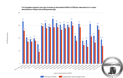
Гистограмма среднего расхода топлива на МАН по сериям.
От
evgenich
Один из вариантов, статистических данных по расходу топлива на МАН.
Данные , усредненные , и конечно, для разных регионов РФ, необходима существенная коррекция показателей.
Обсуждение на форуме здесь:
71 раз скачали
Обновлено 19 апреля, 2019
Замена фильтров мочевины
От
evgenich
Замена фильтров мочевины
62 раза скачали
Отправлено 3 ноября, 2015
Замена приводных ремней
От
evgenich
Замена приводных ремней
62 раза скачали
Отправлено 3 ноября, 2015
Замена приводных ремней d2866 76
От
evgenich
Замена приводных ремней d2866 76
52 раза скачали
Отправлено 3 ноября, 2015
Замена приводных ремней
От
evgenich
Замена приводных ремней
42 раза скачали
Отправлено 3 ноября, 2015
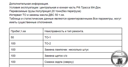
Статистика затрат на ТО и ТР для МАН ТГС 4*2
От
evgenich
Статистика затрат на ТО и ТР для МАН ТГС 4*2
Хороший статистический перечень работ по ТО и ТР, для тягача МАН ТГС, с 0 идо 650 т.км. пробега
Активная тема на форуме здесь:http://форум-ман.рф/index.php?/topic/10710-man-tgs-42statistika-po-remontu-3goda650tkm/
41 раз скачали
Обновлено 19 апреля, 2019
Смазка тормозных валов барабанные тормоза TGA TGS TGX
От
evgenich
Смазка тормозных валов барабанные тормоза TGA TGS TGX
39 раз скачали
Отправлено 11 октября, 2015
MAN M 2000- руководство по ремонту
От
4WDvod
MAN M 2000- руководство по ремонту. Взято из энциклопедии autogeriko.com
5 раз скачали
Отправлено 11 августа, 2022
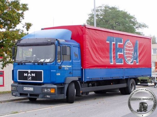
MAN L 2000- руководство по ремонту.
От
4WDvod
MAN L 2000- руководство по ремонту. Взято из энциклопедии autogeriko.com
5 раз скачали
Отправлено 11 августа, 2022
- Главная
- MAN
- TGA
MAN TGA относится к категории крупногабаритных грузовиков производства немецкой компании, отличающихся отличными техническими характеристиками. Техника данного типа используется для перевозки грузов различного типа.
В данном разделе можно найти подробные руководства по эксплуатации для правильного содержания и обслуживания MAN TGA. Также здесь представлены и книги по ремонту, в которых содержатся подробные инструкции по поиску поломок и их устранению. Пособия можно заказать в формате PDF, который очень удобно использовать на различных современных устройствах. Скачать такие издания можно также и в иных форматах.
Обновление цен:
05.09.2023
Диапазон цен:
818 — 2725 руб.
Электросхемы: инструкция по ремонту MAN TGA с 2000 г.
Книга по ремонту MAN TGA предназначена для использования с автомобилями данной модели, выпущенными после 2000 года и оснащенными дизельными двигателями объемом 6.9, 10.5, 12.0, 12.4, 12.8 и 18.3 литра.
- от 818 руб.
- 2000 — 2023 гг.
- дизель
- скачать
МАН
MAN TG-A Руководство по эксплуатации и инструкции по уходу за автомобилем на русском языке
Формат: PDF
Качество:отличное
Язык: Русский
Количество страниц: 491
размер 232 мегабайта
тягач MAN
- Выдержки с форумов.
- Просмотров: 1841
добрый день всем,подскажите пожалуйста хочу взять тягач MAN TGA 18.430 для работы,как вы думаете правильный ли выбор я сделал,только не могу решить с какой колесной базой взять,2Х4 или 2Х6? если не трудно может посоветуете что не будь другое,заранее большое спасибо.
Давайте для начала уточним: 4Х2 , 6Х2 и т.д. колесная формула. Колесная база — расстояние между осями. У европейских тягачей 4Х2 она от 3550мм на некоторых моделях Скании до 4200мм на Рено Магнум.
При современных разрешениях по осевым нагрузкам значимость 6Х2 сведена к минимуму.
Что за прицеп и груз собираешься возить?
Ну Отец Родной слушай. Колесная база в вопросе вторична. Главное нужен ли тебе Ман? Отвечаю. Не нужен. Это достаточно дорогой в обслуживании автомобиль. Гораздо дешевле DAF95XF. Простой пример. Дафу при замене масла требуется 25 литров. МАН потребует 42 литра. Вот вам и разница. Диагностика и ремонт топливной системы ДАФ-ов в разы проще и дешевле чем у МАН при тех же условиях. Про колесную базу!
Вы что возить будете? Может песок с карьера? Тогда берите 2 Х6, если метал, тоже подойдет. Пустые коробки или памперсы сможет отвезти и 2Х4.
Что это за мотор такой на ДАФе с объемом масла 25 л? На XF95 объем моторного масла 33 л. На MAN в зависимости от мотора от 35 до 38л. Эта разница смешна, по сравнению с разницей по топливной экономичности. DAF в этом отношении один из худших европейских производителей.
О подвеске кабины 95-го, уровне антифриза ОЖ и вообще страсти к «течке» ОЖ, проводке под передним бампером и т.д. только ленивый не говорит. А насколько нежные плунжерные пары и самое главное сколько они стоят (!) — отдельный сказ.
DAF — хорошая простая машина, не лишенная родовых болячек. Но любят ее в основном за дешевизну на вторичном рынке.
MAN — действительно непростой автомобиль, но при наличии под боком грамотного сервиса и изначально грамотно эксплуатировавшейся машины будет более выгодным предложением.
И еще. Оба производителя используют одинаковую КПП ZF с роботизированным приводом. А вот программы управления у каждого свои. Если на MAN эта КПП одна из лучших (вместе с вольвовской I-Shift), то на DAF — это «тупая» КПП , еще более увеличивающая расход топлива, особенно на порожнем автомобиле
Re: На D20 42 л. Но дело не в этом. А сроки замены? А масло какое нужно? Если лить что подешевле, и менять каждые 10-20 т.км., тогда да, это важно. Но это, например, как судить о расходе топлива, по емкости топливного бака. Если уж колесная формула вторична, то конкретно объем масла, дело вообще десятое.
По счету это не заметно 🙂
На D28 были варианты с 38л
спасибо друг,обязательно возьму твою информацию к размышлению.
да…согласен…у друга есть 1 ман и 1 даф … тягают тонары — оба 2х4…у нас на юге зимы считай нет — 2х4 вполне хватает…суть в другом…даф в большинстве случаев сами делают и обслуживают…а ман если вдруг что случилось — сразу на сервис…особенно по электронике…1 раз вообще из москвы приезжали какие то мастера делать…думайте сами…что вам больше подходит… а по качеству впринцепе одинако наверно будет… и тот и тот немец… в любом случае решать вам…
Поправлю Витька. МАН — немец. ДАФ -голландец. У мана, топливная система с электронно-управляемым рядным насосом, у ДАФа система UPEC управляемые насосные секции. По виду это напоминает ТНВД прошлых лет, но есть главное различие, при любом ремонте снимать его не надо, как на Мане, Просто снимаешь неисправную секцию и все. Замена по времени занимает не больше 30 минут. Форсунки обычные, стоят в голове. На мане снятие насоса, для человека не посвященного целый ритуал, и вряд ли он без соответствующих умений, инструмента справиться с этим.
DAF — это обкурившийся немец)))
РУКОВОДСТВО ПО ЭКСПЛУАТАЦИИ И ТЕХНИЧЕСКОМУ ОБСЛУЖИВАНИЮ
ТЕХНИЧЕСКИЕ ДАННЫЕ АВТОМОБИЛЯ 3
ПАРАМЕТРЫ ДВИГАТЕЛЯ, ВЕЛИЧИНЫ ДЛЯ КОНТРОЛЯ И РЕГУЛИРОВОЧНЫХ РАБОТ 6
СИСТЕМА СМАЗКИ 7
ТОПЛИВНЫЙ ФИЛЬТР 7
КЛИНОВОЙ РЕМЕНЬ (МНОГОСЛОЙНЫЙ РЕМЕНЬ V-ОБРАЗНОГО ПРОФИЛЯ) 8
СЦЕПЛЕНИЕ 8
КОРОБКА ПЕРЕДАЧ 8
РУЛЕВОЕ УПРАВЛЕНИЕ 8
ПЕРЕДНИЙ МОСТ 8
ЗАДНИЙ МОСТ 9
КОЛЕСА И ШИНЫ 9
ПОДВЕСКА 10
ТОРМОЗНАЯ СИСТЕМА 11
ЭЛЕКТРИЧЕСКАЯ СИСТЕМА 12
ЗАПРАВОЧНЫЕ ОБЪЕМЫ ТЕХНИЧЕСКИХ ЖИДКОСТЕЙ (В ЛИТРАХ) 12
ХОЛОДИЛЬНИК 13
СОКРАЩЕНИЯ, ПРИНЯТЫЕ В КНИГЕ 13
ИНСТРУКЦИЯ ПО ЭКСПЛУАТАЦИИ 16
ЗАМКИ ДВЕРЕЙ, ЗАМОК ЦЕНТРАЛЬНЫЙ 16
НАРУЖНЫЙ БАРДАЧОК КАБИНЫ 17
КРЕСЛА ВОДИТЕЛЯ И ПАССАЖИРА 18
ПОДОГРЕВ СИДЕНЬЯ 22
РЕГУЛИРОВКА ПОЛОЖЕНИЯ РУЛЕВОГО КОЛЕСА 24
РЕМНИ БЕЗОПАСНОСТИ 25
ЭЛЕМЕНТЫ УПРАВЛЕНИЯ 27
ПРИБОРНАЯ ПАНЕЛЬ 28
ВЫКЛЮЧАТЕЛИ И КЛАВИШИ 29
КОНТРОЛЬНЫЕ И ПРЕДУПРЕЖДАЮЩИЕ ЛАМПЫ 29
ДИСПЛЕЙ АВТОМОБИЛЕЙ 2000 ГОДА 29
БЛОК СИГНАЛЬНЫХ ЛАМП 31
ИНФОРМАЦИЯ И УКАЗАНИЯ 40
СТРУКТУРА МЕНЮ НА ДИСПЛЕЕ ВОДИТЕЛЯ 46
ОТОБРАЖЕНИЕ ТЕКУЩЕГО ВРЕМЕНИ ИЛИ ТЕМПЕРАТУРЫ ОКРУЖАЮЩЕЙ СРЕДЫ 49
УСТАНОВКА ТОЧНОГО ВРЕМЕНИ 50
КОМБИНИРОВАННЫЙ ВЫКЛЮЧАТЕЛЬ 51
ЭЛЕКТРОННЫЙ БЛОК УПРАВЛЕНИЯ ДВЕРЬМИ (ВОДИТЕЛЬСКАЯ ДВЕРЬ) 53
СИСТЕМА ЗАМКОВ С ЦЕНТРАЛЬНЫМ УПРАВЛЕНИЕМ 54
ЭЛЕКТРИЧЕСКИЙ СТЕКЛОПОДЪЕМНИК 54
РЕГУЛИРОВКА ПОЛОЖЕНИЯ НАРУЖНОГО ЗЕРКАЛА 54
ПОДОГРЕВ ЗЕРКАЛА 55
СИРЕНА/ЗВУКОВОЙ СИГНАЛ 56
ПРИКУРИВАТЕЛЬ 56
ШТЕПСЕЛЬНАЯ РОЗЕТКА НА 12В/24В 56
ПОДОГРЕВ ВЕТРОВОГО СТЕКЛА 57
СОЛНЦЕЗАЩИТНЫЙ КОЗЫРЕК 57
ОСВЕЩЕНИЕ 57
ТОРМОЗНАЯ СИСТЕМА С ЭЛЕКТРОННЫМ УПРАВЛЕНИЕМ (EBS) 64
АНТИПРОБУКСОВОЧНАЯ СИСТЕМА (ASR) 67
СТОЯНОЧНЫЙ ТОРМОЗ (РУЧНОЙ ТОРМОЗ) 69
ЛИНЕЙНЫЙ ТОРМОЗ (ПО ЗАКАЗУ) 70
ТОРМОЗ-ЗАМЕДЛИТЕЛЬ 71
РЕТАРДЕР 71
ЭЛЕМЕНТЫ УПРАВЛЕНИЯ ОТОПИТЕЛЕМ И ВЕНТИЛЯЦИЕЙ 74
ЛЮК В КРЫШЕ КАБИНЫ 78
СДВИЖНАЯ/ОТКИДНАЯ КРЫША (только в кабинах с высоким потолком) 78
ОБЩИЕ СВЕДЕНИЯ О РАБОТЕ ОТОПИТЕЛЯ 80
ДОПОЛНИТЕЛЬНЫЕ ОТОПИТЕЛИ/УСТРОЙСТВА ДЛЯ ПРЕДВАРИТЕЛЬНОГО ПРОГРЕВА ДВИГАТЕЛЯ 80
АВТОМОБИЛИ МОДЕЛИ CNG 81
ДОПОЛНИТЕЛЬНЫЙ ВОДЯНОЙ ОТОПИТЕ ЛЬ 81
ДОПОЛНИТЕЛЬНЫЕ ОТОПИТЕЛИ 83
ДОПОЛНИТЕЛЬНЫЙ ВОЗДУШНЫЙ ОТОПИТЕЛЬ 87
ДОПОЛНИТЕЛЬНЫЙ ГАЗОВЫЙ ОТОПИТЕЛЬ «TRUMA» МАРКИ TRUMATIC Е 2400 90
ТАЙМЕР ФИРМЫ «TRUMA» 91
ПНЕВМАТИЧЕСКАЯ ПОДВЕСКА С ЭЛЕКТРОННЫМ УПРАВЛЕНИЕМЕСАЭ 92
ЦЕНТРАЛИЗОВАННАЯ СИСТЕМА СМАЗКИ «ВЕКА-MAX» 97
ПОДДЕРЖИВАЮЩИЙ МОСТ (НЕ УПРАВЛЯЕМЫЙ) 99
ОБТЕКАТЕЛЬ НА КРЫШЕ КАБИНЫ/АЭРОДИНАМИЧЕСКИЙ СПОЙЛЕР 99
ПЕРЕДНЯЯ РЕШЕТКА КАБИНЫ 100
БОКОВОЙ ЗАЩИТНЫЙ БРУС 101
УСТРОЙСТВО ОТКИДЫВАНИЯ КАБИНЫ (С ГИДРАВЛИЧЕСКИМ ПРИВОДОМ) 102
ТЕХНИЧЕСКОЕ ОБСЛУЖИВАНИЕ АВТОМОБИЛЯ 106
ЕЖЕДНЕВНЫЕ РАБОТЫ (ПРОИЗВОДИМЫЕ ПЕРЕД ЗАПУСКОМ ДВИГАТЕЛЯ) 106
ЕЖЕНЕДЕЛЬНОЕ ОБСЛУЖИВАНИЕ (ПЕРЕД ЗАПУСКОМ ДВИГАТЕЛЯ) 109
ЕЖЕМЕСЯЧНОЕ ТЕХОБСЛУЖИВАНИЕ(ПЕРЕД ЗАПУСКОМ ДВИГАТЕЛЯ) 110
ТЕХОБСЛУЖИВАНИЕ АВТОМОБИЛЯ РАЗ В ПОЛГОДА (ПЕРЕД ЗАПУСКОМ ДВИГАТЕЛЯ) 111
ЕЖЕДНЕВНЫЕ ПРОВЕРКИ (ПОСЛЕ ЗАПУСКА ДВИГАТЕЛЯ) 111
ЕЖЕНЕДЕЛЬНЫЕ ПРОВЕРКИ (ПОСЛЕ ЗАПУСКА ДВИГАТЕЛЯ) 112
ЕЖЕМЕСЯЧНЫЕ ПРОВЕРКИ ПОСЛЕ ЗАПУСКА ДВИГАТЕЛЯ 113
ЭКСПЛУАТАЦИЯ АВТОМОБИЛЯ 114
РЕЖИМ ДВИЖЕНИЯ 114
ТОРМОЗНАЯ СИСТЕМА 114
СИСТЕМА ОХЛАЖДЕНИЯ ДВИГАТЕЛЯ 114
МАСЛО В ДВИГАТЕЛЕ 116
УСТРОЙСТВО ОТКИДЫВАНИЯ КАБИНЫ 116
ОПРОКИДЫВАЮЩИЙСЯ КУЗОВ САМОСВАЛА 116
ГИДРОПРИВОД РУЛЕВОГО УПРАВЛЕНИЯ 117
ТАХОМЕТР 117
УСТРОЙСТВО ОГРАНИЧЕНИЯ СКОРОСТИ ДВИЖЕНИЯ 117
ВЫКЛЮЧАТЕЛЬ НА КОЛОНКЕ РУЛЕВОГО УПРАВЛЕНИЯ 118
РЕГУЛИРОВКА СКОРОСТИ ДВИЖЕНИЯ АВТОМОБИЛЯ 118
РЕГУЛЯТОР СКОРОСТИ ДВИЖЕНИЯ FGR -ТЕМПОМАТ 119
ОГРАНИЧИТЕЛЬ СКОРОСТИ ДВИЖЕНИЯ МАШИНЫ FGB 120
ДИАГНОСТИКА НЕИСПРАВНОСТЕЙ 121
ПРАВИЛА ЗАГРУЗКИ МАШИНЫ 121
ЗАПУСК ДВИГАТЕЛЯ 122
ВЫКЛЮЧЕНИЕ ДВИГАТЕЛЯ 126
КОРОБКИ ПЕРЕКЛЮЧЕНИЯ ПЕРЕДАЧ 127
КОРОБКИ ПЕРЕДАЧ МАРОК ZF-16S51/181/221 ECOSPLIT 127
АВТОМАТИЧЕСКАЯ КОРОБКА ПЕРЕДАЧ ZF 5/6 HP 130
АВТОМАТИЧЕСКАЯ КОРОБКА ПЕРЕДАЧ ZF-AS TRONIC 132
ПЕРЕКЛЮЧЕНИЕ ПЕРЕДАЧ В АВТОМАТИЧЕСКОЙ КОРОБКЕ ПЕРЕДАЧ ZF-AS TRONIC 12 AS 2301 136
МЕХАНИЗМ ОТБОРА МОЩНОСТИ «ZF-ECOSPLIT», ИСПОЛЬЗУЮЩИЙ ПРИВОД ОТ ДВИГАТЕЛЯ АВТОМОБИЛЯ 138
МЕХАНИЗМ ОТБОРА МОЩНОСТИ «ZF-ECOSPLIT» С ПРИВОДОМ ОТ КОРОБКИ ПЕРЕДАЧ 139
БЛОКИРОВКИ ДИФФЕРЕНЦИАЛА 141
ЕЗДА ПО ПЕРЕСЕЧЕННОЙ МЕСТНОСТИ 142
РАБОТА АВТОМОБИЛЯ С ПРИЦЕПОМ 142
ТЯГОВО-СЦЕПНЫЕ УСТРОЙСТВА 144
ПРИЦЕП НА ЖЕСТКОЙ СЦЕПКЕ (ЦЕНТРАЛЬНО-ОСЕВОЕ ТЯГОВО-СЦЕПНОЕ УСТРОЙСТВО) 146
ОБЩИЕ СВЕДЕНИЯ ПО ЭКСПЛУАТАЦИИ ПОЛУПРИЦЕПА 147
СЕДЕЛЬНО-СЦЕПНЫЕ УСТРОЙСТВА 149
СМЕННЫЙ КУЗОВ 151
ЗАМЕНА КОЛЕСА 152
ТОЧКИ УСТАНОВКИ ДОМКРАТА 153
БУКСИРОВКА НЕИСПРАВНОГО АВТОМОБИЛЯ 155
ЗАПУСК ДВИГАТЕЛЯ С ПОМОЩЬЮ АККУМУЛЯТОРА ДРУГОЙ МАШИНЫ 158
АВАРИЙНОЕ ОТПУСКАНИЕ ТОРМОЗНОГО ЦИЛИНДРА ПРУЖИННОГО ЭНЕРГОАККУМУЛЯТОРА 159
МЕХАНИЧЕСКОЕ ВЫСВОБОЖДЕНИЕ ПРУЖИННОГО ЭНЕРГОАККУМУЛЯТОРА 160
КЛИНОВЫЕ РЕМНИ 161
ТОПЛИВНАЯ СИСТЕМА 161
ЭЛЕКТРООБОРУДОВАНИЕ 162
ЗАМЕНА ЛАМП НАКАЛИВАНИЯ 164
ЗАМЕНА МАСЛА И МАСЛЯНОГО ФИЛЬТРА 166
СУХОЙ ВОЗДУШНЫЙ ФИЛЬТР 169
КАТАЛОГ ДЕТАЛЕЙ
СТЕКЛООЧИСТИТЕЛИ 173
КОРОБКИ ПЕРЕДАЧ 174
КОРПУС ТРАНСМИССИИ И КАРТЕР СЦЕПЛЕНИЯ 174
ТРУБКА РАСПЫЛИТЕЛЯ И МАСЛЯНЫЙ ФИЛЬТР 175
БЛОК УПРАВЛЕНИЯ 176
КРЫШКА КАРТЕРА 177
ПРУЖИНЫ. КОРОБКА УПРАВЛЕНИЯ 179
КОРПУС ТРАНСМИССИИ И КАРТЕР СЦЕПЛЕНИЯ 180
КАРТЕР СЦЕПЛЕНИЯ 181
КОРЗИНА СЦЕПЛЕНИЯ (FICHTEL & SACHS) 182
БОЛТЫ СЦЕПЛЕНИЯ (FICHTEL & SACHS, VALEO) 182
УПЛОТНЕНИЯ ИНТАРДЕРА 183
КАРТЕР СЦЕПЛЕНИЯ 183
ДЕТАЛИ ГЛАВНОГО ВАЛА 184
ПРИВОДНОЙ ВАЛ С СОЕДИНИТЕЛЬНОЙ ПЛАСТИНОЙ 185
ПРОМЕЖУТОЧНЫЙ ВАЛ С НАСОСОМ И ШЕСТЕРНЯ ЗАДНЕГО ХОДА 187
ВЫХОД ОТБОРА МОЩНОСТИ 188
НАСОС ИНТАРДЕРА 189
УПРАВЛЕНИЕ ОТБОРА МОЩНОСТИ 190
КОРПУС ИНТАРДЕРА 191
УПРАВЛЕНИЕ ИНТАРДЕРА 192
ДЕТАЛИ СИНХРОНИЗАТОРА 193
ДЕТАЛИ ПЕРЕДНЕГО ГЛАВНОГО ВАЛА 194
КОРОБКА ПЕРЕКЛЮЧЕНИЯ ПЕРЕДАЧ И УПРАВЛЯЮЩИЙ ВАЛ 195
СЕРВОПРИВОД 196
УПРАВЛЕНИЕ ПЕРЕКЛЮЧЕНИЕМ ПЕРЕДАЧ 197
КРЫШКА КАРТЕРА GP 198
ПЛАНЕТАРНАЯ ПЕРЕДАЧА 199
ДЕТАЛИ СИНХРОНИЗАТОРА 200
КАРТЕР ТРАНСМИССИИ I 200
КАРТЕР ТРАНСМИССИИ II 201
ВЕДУЩИЙ ВАЛ 202
ПРОМЕЖУТОЧНЫЕ ВАЛЫ 204
ГЛАВНЫЙ ВАЛ 205
ПЛАНЕТАРНАЯ ПЕРЕДАЧА 206
КАРТЕР GP 207
ЗАДНИЙ ХОД 209
ЦИЛИНДР СЦЕПЛЕНИЯ 209
УПРАВЛЕНИЕ 210
УПРАВЛЕНИЕ GP 211
УПРАВЛЕНИЕ GV 211
УПРАВЛЕНИЕ СЦЕПЛЕНИЕМ 212
СЦЕПЛЕНИЕ 214
ТРУБОПРОВОД СЦЕПЛЕНИЯ 215
РЕМКОМПЛЕКТ РАБОЧЕГО ЦИЛИНДРА СЦЕПЛЕНИЯ 216
КАРТЕР ИНТАРДЕРА 217
БЛОК УПРАВЛЕНИЯ КОРОБКОЙ ПЕРЕДАЧ GS3 218
ВЫХОДНОЙ ФЛАНЕЦ 218
МОНТАЖНЫЕ ДЕТАЛИ КАРТЕРА ИНТАРДЕРА 219
ДЕТАЛИ ГЛАВНОГО ВАЛА 220
ШТОК ПЕРЕКЛЮЧЕНИЯ 221
ДЕТАЛИ МЕХАНИЗМА ПЕРЕКЛЮЧЕНИЯ 222
СОЕДИНЕНИЯ КОРОБКИ УПРАВЛЕНИЯ 223
СОЕДИНЕНИЯ КЛАПАНА БЛОКИРОВКИ КОРОБКИ УПРАВЛЕНИЯ 224
КОРОБКА УПРАВЛЕНИЯ И УПРАВЛЯЮЩИЙ ВАЛ 225
СЕРВОПРИВОД 226
ВИЛКА СЦЕПЛЕНИЯ 228
ПРУЖИНЫ И УПРАВЛЯЮЩИЙ ВАЛ 228
КОРОБКА УПРАВЛЕНИЯ 229
КАРТЕР ТРАНСМИССИИ 230
КАРТЕР СЦЕПЛЕНИЯ, ОТБОР МОЩНОСТИ ПЕРЕД КОРОБКОЙ ПЕРЕДАЧ 231
ВЕДУЩИЙ ВАЛ КОРОБКИ ПЕРЕДАЧ 232
ПРОМЕЖУТОЧНЫЙ ВАЛ КОРОБКИ ПЕРЕДАЧ 233
ПРИВОДНОЙ ВАЛ ОТБОРА МОЩНОСТИ 234
УПРАВЛЕНИЕ GP 235
КАРТЕР ТРАНСМИССИИ I 236
КАРТЕР ТРАНСМИССИИ 237
УПРАВЛЕНИЕ ОТБОРОМ МОЩНОСТИ 238
ТОРМОЗНАЯ СИСТЕМА 244
ТОРМОЗНОЙ БАРАБАН 244
РЕМКОМПЛЕКТ РЕГУЛЯТОРА ЗАЗОРА 244
АНКЕРНЫЙ ТОРМОЗНОЙ КРОНШТЕЙН 245
БЛОКИРОВКА ДИФФЕРЕНЦИАЛА 246
ВЕДУЩИЙ ВАЛ СКВОЗНОЙ ПЕРЕДАЧИ 247
СКВОЗНАЯ ПЕРЕДАЧА, УПРАВЛЕНИЕ 248
ГЛАВНЫЙ ВАЛ С БЛОКИРОВКОЙ ДИФФЕРЕНЦИАЛА 249
СКВОЗНАЯ ПЕРЕДАЧА 250
ДИФФЕРЕНЦИАЛ 251
ПОДШИПНИК КОНИЧЕСКОЙ ШЕСТЕРНИ 252
БЛОКИРОВКА ДИФФЕРЕНЦИАЛА 253
ЗАДНИЙ МОСТ (ДИСКОВЫЕ ТОРМОЗА) 253
ВАЛ 254
ВЕДУЩИЙ ВАЛ 255
ТОРМОЗНОЙ ДИСК, СТУПИЦА КОЛЕСА 255
СТУПИЦА КОЛЕСА, ПНЕВМОПОДВЕСКА 256
ЗАДНИЙ МОСТ 257
ВАЛИК ТОРМОЗНОГО КУЛАКА 258
ДАТЧИК ИЗНОСА 260
ДАТЧИК СКОРОСТИ 260
БЛОКИРОВКА ДИФФЕРЕНЦИАЛА 261
ДИФФЕРЕНЦИАЛ 262
ТОРМОЗНАЯ КОЛОДКА 264
КРЕПЛЕНИЕ ДАТЧИКА 265
ОБОД С ЦЕНТРИРОВАНИЕМ СТУПИЦЫ 266
ТОРМОЗНОЙ ДИСК 266
СТУПИЦА КОЛЕСА, ТОРМОЗНОЙ ДИСК 267
ДАТЧИК ИЗНОСА ТОРМОЗНОЙ НАКЛАДКИ 268
РЕМКОМПЛЕКТЫ СУППОРТА, ДИСКОВЫЙ ТОРМОЗ 268
ДАТЧИК СКОРОСТИ 269
КОЛЕСНЫЙ ДИСК, ЗАДНИЙ МОСТ 270
КОЛЕСНЫЙ ДИСК ПЕРЕДНЕГО МОСТА 270
ДИСКОВЫЕ ТОРМОЗА, РЕМКОМПЛЕКТЫ СУППОРТА 271
ШАЙБА РЕГУЛЯТОРА ЗАЗОРА 273
ГЛАВНЫЙ ВАЛ С БЛОКИРОВКОЙ ДИФФЕРЕНЦИАЛА 274
КАРДАННЫЙ ВАЛ 275
КАРДАННЫЕ ВАЛЫ С ДЕРЖАТЕЛЕМ 275
ПРОМЕЖУТОЧНЫЙ ПОДШИПНИК С ФЛАНЦЕМ 280
ЗАДНЕЕ СЦЕПНОЕ ПРИСПОСОБЛЕНИЕ 280
СЦЕПНОЕ УСТРОЙСТВО 282
ДЕТАЛИ СЦЕПНОГО УСТРОЙСТВА 289
РАМА 290
ПЛАСТМАССОВЫЙ БАМПЕР 291
КРОНШТЕЙН ПЛАСТМАССОВОГО БАМПЕРА 292
ПЕРЕДНЯЯ ПОПЕРЕЧИНА И КРОНШТЕЙН СТАЛЬНОГО БАМПЕРА 293
СТАЛЬНОЙ БАМПЕР, ЦЕНТРАЛЬНАЯ ЧАСТЬ 294
УГЛЫ СТАЛЬНОГО БАМПЕРА 295
НАКЛАДКА СТАЛЬНОГО БАМПЕРА 296
ОПОРНЫЙ КРОНШТЕЙН СТАЛЬНОГО БАМПЕРА 296
ПОПЕРЕЧИНА НАД КОРОБКОЙ ПЕРЕДАЧ 297
ПЕРЕДНЯЯ ПОПЕРЕЧИНА И КРОНШТЕЙН СТАЛЬНОГО БАМПЕРА 298
СТАЛЬНОЙ БАМПЕР, ЗАЩИТА РАДИАТОРА 298
ПОДНОЖКА ПОД СТАЛЬНЫМ БАМПЕРОМ 300
НИЖНЯЯ ПОДНОЖКА СТАЛЬНОГО БАМПЕРА 301
ПРОТИВОПОДКАТНОЕ ОГРАЖДЕНИЕ И КРОНШТЕЙН ЗАДНЕГО ОСВЕЩЕНИЯ 302
ПРОТИВОПОДКАТНОЕ ОГРАЖДЕНИЕ ЗАДНЕЕ 304
ПРОТИВОПОДКАТНОЕ ОГРАЖДЕНИЕ ПЕРЕДНЕЕ (ПОД БАМПЕРОМ) 305
ПОДНОЖКА НИЖНЯЯ 306
КРОНШТЕЙН ПОДНОЖКИ 307
ПОПЕРЕЧИНА И КРОНШТЕЙНЫ 308
ЦЕНТРАЛЬНАЯ НАКЛАДКА СТАЛЬНОГО БАМПЕРА 309
КРЕПЛЕНИЕ V-ОБРАЗНОЙ ШТАНГИ 310
РЕЗИНОМЕТАЛЛИЧЕСКАЯ ПРОКЛАДКА 311
ПНЕВМОБАЛЛОНЫ 312
СТАБИЛИЗАТОР ПЕРЕДНЕГО МОСТА 312
КРЕПЛЕНИЕ РЕАКТИВНОЙ ШТАНГИ 313
СТАБИЛИЗАТОР ЗАДНЕГО МОСТА 314
АМОРТИЗАТОР 315
КРОНШТЕЙН И АМОРТИЗАТОР 317
Х-ОБРАЗНАЯ ШТАНГА 318
РЕАКТИВНАЯ ШТАНГА, ПЕРЕДНИЙ МОСТ 319
ПЕРЕДНИЙ НЕВЕДУЩИЙ МОСТ ПОВОРОТНЫЙ КУЛАК 320
РУЛЕВАЯ ТЯГА 321
ДЕТАЛИ ЛЕБЕДКИ ЗАПАСНОГО КОЛЕСА 81.42401-6172 322
ЛЕБЕДКА ЗАПАСНОГО КОЛЕСА, БОКОВАЯ 323
БАЧОК ГИДРАВЛИЧЕСКОЙ ЖИДКОСТИ РУЛЕВОГО УПРАВЛЕНИЯ С КОНТРОЛЕМ УРОВНЯ 324
РУЛЕВОЕ УПРАВЛЕНИЕ 325
РУЛЕВАЯ СОШКА И ПРОДОЛЬНАЯ РУЛЕВАЯ ТЯГА LM 325
РУЛЕВАЯ КОЛОНКА 326
КОЖУХ РУЛЕВОГО ВАЛА 327
РЕМКОМПЛЕКТ РУЛЕВОГО УПРАВЛЕНИЯ 328
КРОНШТЕЙН РУЛЕВОГО УПРАВЛЕНИЯ 329
ПЕДАЛЬНЫЙ УЗЕЛ 330
УНИВЕРСАЛЬНЫЙ РУЛЕВОЙ ВАЛ, АМОРТИЗАТОР 331
СМАЗОЧНАЯ СИСТЕМА СЦЕПНОГО УСТРОЙСТВА 332
ЦЕНТРАЛЬНЫЙ СМАЗЫВАЮЩИЙ НАСОС 333
ТОРМОЗНАЯ СИСТЕМА 335
СХЕМА АНТИБЛОКИРОВОЧНОЙ ТОРМОЗНОЙ СИСТЕМЫ (ABS) 339
СХЕМА ПНЕВМОПОДВЕСКИ КАБИНЫ 339
СХЕМА ПЕРЕДНИХ СОЕДИНЕНИЙ ТОРМОЗНОЙ СИСТЕМЫ 340
СХЕМА ПНЕВМОПОДВЕСКИ 341
ПНЕВМАТИЧЕСКОЕ УПРАВЛЕНИЕ ПРИТАРДЕРОМ 342
РЕМКОМПЛЕКТ КЛАПАНА ПЕРЕГРУЗКИ 343
ТОРМОЗНОЙ ЦИЛИНДР 344
РЕМКОМПЛЕКТ ВОЗДУХООСУШИТЕЛЯ 345
РЕМКОМПЛЕКТ ЭЛЕКТРОМАГНИТНОГО КЛАПАНА ECAS 346
РЕМКОМПЛЕКТ КОНТРОЛЬНОГО КЛАПАНА ПРИЦЕПА WABCO-WESTINGHOUSE 346
РЕМКОМПЛЕКТ КЛАПАНА ОГРАНИЧЕНИЯ ДАВЛЕНИЯ 347
КУЗОВНЫЕ ЭЛЕМЕНТЫ КАБИНЫ 347
БОКОВИНА 347
ПЕРЕГОРОДКА 348
ПЕРЕГОРОДКА ВЕРХНЯЯ 348
ЛЕВАЯ БОКОВАЯ ПАНЕЛЬ 349
ВНЕШНЯЯ БОКОВАЯ ПАНЕЛЬ 349
ВНУТРЕННЯЯ БОКОВАЯ ПАНЕЛЬ 350
ЗАДНЯЯ ПАНЕЛЬ 350
ЗАДНЯЯ СТЕНОВАЯ ПАНЕЛЬ 351
ЗАДНЯЯ КРЫШКА ЗАДНЕЙ ПАНЕЛИ 351
ЗАЩИТА 353
ДЕРЖАТЕЛЬ БОКОВОЙ ПАНЕЛИ 354
БОКОВАЯ ПАНЕЛЬНАЯ ОБШИВКА 354
БОКОВЫЕ ОКНА 355
ЛЕВЫЙ ЭЛЕКТРИЧЕСКИЙ СТЕКЛОПОДЪЕМНИК 356
ЛЕВЫЙ МЕХАНИЧЕСКИЙ СТЕКЛОПОДЪЕМНИК 356
ВЕТРОВОЕ СТЕКЛО 357
КРЫША 358
ЛЮК 358
КРЕПЕЖ КРЫШИ 359
ДВЕРНОЙ ЗАМОК ЛЕВЫЙ ВНУТРЕННИЙ 360
ЦИЛИНДР ПОДЪЕМНОГО НАСОСА МЕХАНИЗМА НАКЛОНА КАБИНЫ 361
ЦИЛИНДР МЕХАНИЗМА НАКЛОНА КАБИНЫ 362
ЦИЛИНДР И ПОДЪЕМНЫЙ НАСОС МЕХАНИЗМА НАКЛОНА КАБИНЫ 363
ПЕРЕДНЯЯ ПОДВЕСКА КАБИНЫ 364
ЗАДНЯЯ ПОДВЕСКА КАБИНЫ 366
КОЖУХ КРЫШКИ МЕХАНИЧЕСКОЙ КОРОБКИ ПЕРЕДАЧ 368
КРЕПЛЕНИЕ ТЕПЛООБМЕННИКА 369
ФИЛЬТР 369
ДЕТАЛИ ФИЛЬТРА, ИСПАРИТЕЛЬ, РАСШИРИТЕЛЬНЫЙ КЛАПАН 370
КОМПОНЕНТЫ ФИЛЬТРА 371
ВОЗДУХОВОД 372
НАГРЕВАТЕЛЬНЫЕ ТРУБОПРОВОДЫ 374
СПОЙЛЕР 376
ЗАДНИЙ КЛАПАН КОНТРОЛЯ УРОВНЯ 380
КЛАПАН КОНТРОЛЯ УРОВНЯ, ПЕРЕДНИЙ 381
КАБИНА ЗАМЕНЯЕМАЯ 382
ЗЕРКАЛО ЗАДНЕГО ВИДА 383
КРОНШТЕЙН ЗЕРКАЛА ЗАДНЕГО ВИДА 386
ПРОБКА 387
ПРОБКИ ПАНЕЛИ ПОЛА 388
ГАЗОВЫЕ ПРУЖИНЫ ПЕРЕДНЕЙ СЕРВИСНОЙ ДВЕРЦЫ 388
ПЕРЕДНЯЯ СЕРВИСНАЯ РЕШЕТКА 389
ПЕРЕДНЕЕ КРЕПЛЕНИЕ СЕРВИСНОЙ ДВЕРЦЫ 392
СТУПЕНИ И КРЫЛО, ЛЕВЫЕ 394
ПЕРЕДНЕЕ ОГРАЖДЕНИЕ 395
РЕМКОМПЛЕКТЫ ПНЕВМОПОДВЕСКИ 397
РЕМКОМПЛЕКТ ОПОРНОГО РЫЧАГА 398
АККУМУЛЯТОР ДАВЛЕНИЯ, ДЕТАЛИ 400
ДВИГАТЕЛЬ 401
РАМНЫЙ КРОНШТЕЙН КРЕПЛЕНИЯ ДВИГАТЕЛЯ 401
КРЕПЛЕНИЕ ДВИГАТЕЛЯ 403
ПЕРЕДНЯЯ ОПОРА ДВИГАТЕЛЯ 404
КРОНШТЕЙН ДВИГАТЕЛЯ, ПРАВЫЙ 405
КРОНШТЕЙН ДВИГАТЕЛЯ, ЛЕВЫЙ 405
ЗАЩИТА ДВИГАТЕЛЯ 406
ГИЛЬЗА ЦИЛИНДРА И МАСЛОРАСПЫЛИТЕЛЬНАЯ ФОРСУНКА 407
КРЫШКА РАСПРЕДЕЛИТЕЛЬНОГО ВАЛА НА КАРТЕРЕ 408
КРЫШКА МЕХАНИЗМА ГАЗОРАСПРЕДЕЛЕНИЯ 409
ФЛАНЕЦ ДАТЧИКА ТЕМПЕРАТУРЫ ОХЛАЖДАЮЩЕЙ ЖИДКОСТИ 409
КАРТЕР 410
КОЖУХ МЕХАНИЗМА ГАЗОРАСПРЕДЕЛЕНИЯ 412
КОЖУХ МЕХАНИЗМА ГАЗОРАСПРЕДЕЛЕНИЯ, МОНТАЖНЫЕ ДЕТАЛИ 413
КОЖУХ МЕХАНИЗМА ГАЗОРАСПРЕДЕЛЕНИЯ, ЗАМЕНЯЕМЫЕ ЧАСТИ 414
МАСЛООТДЕЛИТЕЛЬ САПУНА ДВИГАТЕЛЯ И МОНТАЖНЫЕ ДЕТАЛИ 415
САПУН ДВИГАТЕЛЯ, МАСЛООТДЕЛИТЕЛЬ И МОНТАЖНЫЕ ДЕТАЛИ 416
СЛИВНАЯ ПРОБКА И УПЛОТНЕНИЕ НА КАРТЕРЕ 418
САЛЬНИК КОЖУХА МЕХАНИЗМА ГАЗОРАСПРЕДЕЛЕНИЯ 418
ПОРШЕНЬ С ШАТУНОМ 419
ПЕРЕДНЯЯ КРЫШКА КОЛЕНЧАТОГО ВАЛА НА КАРТЕРЕ ДВИГАТЕЛЯ 420
МАХОВИК 420
КОЛЕНЧАТЫЙ ВАЛ 421
КОЛЕНЧАТЫЙ ВАЛ С ДЕМПФЕРОМ ВИБРАЦИИ, МОНТАЖНЫЕ ДЕТАЛИ 422
КОЛЕНЧАТЫЙ ВАЛ С ДЕМПФЕРОМ ВИБРАЦИИ, КОРЕННОЙ ПОДШИПНИК, МОНТАЖНЫЕ ДЕТАЛИ 423
ГОЛОВКА ЦИЛИНДРА 424
МОНТАЖНЫЕ ДЕТАЛИ ВЕРХНЕЙ ЧАСТИ ГОЛОВКИ ЦИЛИНДРОВ 425
КРЫШКА ГОЛОВКИ ЦИЛИНДРА 426
ВНУТРЕННЯЯ ПРУЖИНА КЛАПАНА (MAN TGA С ПРИТАРДЕРОМ) 426
КОРПУС ПОДШИПНИКОВ РЫЧАГА КОРОМЫСЛА 427
ТОЛКАТЕЛЬ КЛАПАНА 429
ШЕСТЕРНЯ ПРИВОДА КОМПРЕССОРА 430
РАСПРЕДЕЛИТЕЛЬНЫЙ ВАЛ С ШЕСТЕРНЕЙ 431
СИСТЕМА СМАЗКИ ДВИГАТЕЛЯ 431
МАСЛОЗАБОРНАЯ МАГИСТРАЛЬ И МОНТАЖНЫЕ ДЕТАЛИ 431
МАСЛЯНЫЙ НАСОС СТАНДАРТНОЙ ПРОИЗВОДИТЕЛЬНОСТИ 432
МАСЛОЗАБОРНАЯ МАГИСТРАЛЬ 433
МОНТАЖНЫЕ ДЕТАЛИ МАСЛЯНОГО НАСОСА СТАНДАРТНОЙ ПРОИЗВОДИТЕЛЬНОСТИ 435
МАСЛЯНЫЙ ПОДДОН И МАСЛОСБОРНИК 436
МАСЛОЗАБОРНАЯ ГОРЛОВИНА, МАСЛОМЕРНЫЙ ЩУП 437
ДЕРЖАТЕЛЬ МАСЛЯНОГО ПОДДОНА 438
КРЕПЛЕНИЕ МАСЛЯНОГО ФИЛЬТРА И МОНТАЖНЫЕ ДЕТАЛИ 439
КОМПОНЕНТЫ МАСЛЯНОГО ФИЛЬТРА И МАСЛООХЛАДИТЕЛЬ 440
ВЫВОДЫ И СОЕДИНЕНИЯ МАСЛЯНОГО ФИЛЬТРА 442
МАСЛЯНЫЙ ПОДДОН И МАСЛОСБОРНИК 443
МАСЛОЗАБОРНАЯ ГОРЛОВИНА, МАСЛОМЕРНЫЙ ЩУП 445
МАСЛОЗАБОРНАЯ МАГИСТРАЛЬ, МАСЛОМЕРНЫЙ ЩУП СТРУБКОЙ И КРОНШТЕЙН 446
ТРУБОПРОВОД ПРЕДВАРИТЕЛЬНОГШО НАГРЕВА МАСЛА 447
МАСЛЯНЫЙ ПОДДОН С РЕБРАМИ ЖЕСТКОСТИ 449
МАСЛЯНЫЙ НАСОС СТАНДАРТНОЙ ПРОИЗВОДИТЕЛЬНОСТИ 450
ШКИВ НАТЯЖЕНИЯ БЕЗ АВТОМАТИЧЕСКОГО РЕГУЛЯТОРА 451
СИСТЕМА ОХЛАЖДЕНИЯ ДВИГАТЕЛЯ 452
ВОДЯНОЙ НАСОС 452
УСТАНОВОЧНАЯ ДЕТАЛЬ ВОДЯНОГО НАСОСА 453
ВЕНТИЛЯТОР С ПРОМЕЖУТОЧНЫМ ФЛАНЦЕМ, МОНТАЖНЫЕ ДЕТАЛИ 454
ЭЛЕМЕНТЫ ВОДЯНОГО НАСОСА 455
ВОДЯНОЙ НАСОС, КРЕПЕЖ 456
ПРОМЕЖУТОЧНАЯ ПЛИТА, МОНТАЖНЫЕ ДЕТАЛИ 457
ВЕНТИЛЯТОР 458
ПРОМЕЖУТОЧНАЯ ПЛАСТИНА С 2/2-ХОДОВЫМ КЛАПАНОМ, МОНТАЖНЫЕ ДЕТАЛИ 460
ВЕНТИЛЯТОР И МОНТАЖНЫЕ ДЕТАЛИ 461
ПРОМЕЖУТОЧНАЯ ПЛАСТИНА И МОНТАЖНЫЕ ДЕТАЛИ 462
ПОДШИПНИК ВЕНТИЛЯТОРА 463
ВЕНТИЛЯТОР 464
ОХЛАЖДАЮЩИЙ ТРУБОПРОВОД, ВХОД ВОДЯНОГО НАСОСА 465
ТЕРМОСТАТ 465
КОМПОНЕНТЫ ВОДЯНОГО НАСОСА 466
КРЕПЛЕНИЕ ГИДРАВЛИЧЕСКОГО НАСОСА К КОМПРЕССОРУ 468
МОНТАЖНЫЕ ДЕТАЛИ ВОЗДУХООЧИСТИТЕЛЯ 469
ВЫПУСКНОЙ КОЛЛЕКТОР И ТЕПЛОЗАЩИТА 470
МОДУЛЬ И ЛИНИИ РЕЦИРКУЛЯЦИИ ВЫХЛОПНЫХ ГАЗОВ 473
СРЕДСТВО ОБЛЕГЧЕНИЯ ПУСКА ДВИГАТЕЛЯ 474
ТУРБОКОМПРЕССОР 476
ВОЗВРАТНЫЙ ТРУБОПРОВОД ИЗ ТУРБОКОМПРЕССОРА 477
ВПУСКНОЙ КОЛЛЕКТОР ТУРБОКОМПРЕССОРА 479
ВПУСКНОЙ ПАТРУБОК ТУРБОКОМПРЕССОРА 482
МАСЛЯНЫЕ ТРУБОПРОВОДЫ ТУРБОКОМПРЕССОРА 482
ТОПЛИВНАЯ СИСТЕМА 483
УСТАНОВОЧНЫЕ ДЕТАЛИ ФОРСУНОК 483
ТОПЛИВНЫЕ ТРУБКИ ВЫСОКОГО ДАВЛЕНИЯ 484
ТОПЛИВНЫЙ НАСОС С КРЕПЛЕНИЕМ 484
ТОПЛИВНЫЙ НАСОС С РЕГУЛЯТОРОМ И МОНТАЖНЫЕ ДЕТАЛИ 485
ТОПЛИВНЫЕ ЛИНИИ 486
ДЕТАЛИ ПРЕДВАРИТЕЛЬНОГО ФИЛЬТРА ТОПЛИВА 487
ТОПЛИВНЫЕ ЛИНИИ ОТТОПЛИВНОГО БАКА К ДВИГАТЕЛЮ 488
ТОПЛИВНЫЕ ЛИНИИ ТОПЛИВНОГО НАСОСА ОТОПИТЕЛЯ 489
ТОПЛИВНЫЕ ЛИНИИ 490
ДЕТАЛИ ТОПЛИВНОГО ФИЛЬТРА 491
ТОПЛИВНЫЕ ЛИНИИ 492
ТОПЛИВНЫЙ ФИЛЬТР БЕЗ НАГРЕВА, ДЕТАЛИ И КРЕПЕЖ 494
ТОПЛИВНЫЙ ФИЛЬТР, КОМПОНЕНТЫ И КРЕПЕЖ 495
ПУСТОТЕЛЫЙ БОЛТ СЛИВНОЙ ПРОБКИ 496
КОМПОНЕНТЫ ТОПЛИВНОГО ФИЛЬТРА БЕЗ НАГРЕВА 497
ВЫПУСКНОЙ ТРУБОПРОВОД, СИСТЕМА ТОРМОЖЕНИЯ ДВИГАТЕЛЕМ 498
ПНЕВМОЦИЛИНДР СИСТЕМЫ ТОРМОЖЕНИЯ ДВИГАТЕЛЕМ 499
ВЫПУСКНОЙ ТРУБОПРОВОД, ЦЕНТРАЛЬНЫЙ ГЛУШИТЕЛЬ 500
ИЗГИБ ВЫПУСКНОЙ СИСТЕМЫ 501
ВЕРТИКАЛЬНАЯ ВЫПУСКНАЯ СИСТЕМА 502
ВЫПУСКНОЙ ТРУБОПРОВОД СИСТЕМЫ ТОРМОЖЕНИЯ ДВИГАТЕЛЕМ 504
ДЕТАЛИ ГЕНЕРАТОРА 505
ШКИВ НАТЯЖЕНИЯ 507
ШКИВ НАТЯЖЕНИЯ, УСТАНОВОЧНЫЕ ДЕТАЛИ 508
МОНТАЖНЫЕ ДЕТАЛИ ГЕНЕРАТОРА G12/G17/G24 509
МОНТАЖНЫЕ ДЕТАЛИ НАСОСА ОХЛАЖДАЮЩЕЙ ЖИДКОСТИ 510
МАХОВИК ОТБОРА МОЩНОСТИ, НАСОС ОХЛАЖДАЮЩЕЙ ЖИДКОСТИ 511
ШКИВ НАТЯЖЕНИЯ КОМПРЕССОРА 512
КОМПОНЕНТЫ МЕХАНИЗМА ОТБОРА МОЩНОСТИ 513
МАХОВИК МЕХАНИЗМА ОТБОРА МОЩНОСТИ 514
НАКОНЕЧНИК И КРЕПЛЕНИЕ МЕХАНИЗМА ОТБОРА МОЩНОСТИ 515
РЕМКОМПЛЕКТ ЛОПАСТНОГО НАСОСА 515
НАСОС УСИЛИТЕЛЯ РУЛЕВОГО УПРАВЛЕНИЯ И МОНТАЖНЫЕ ДЕТАЛИ 517
НАСОС ОХЛАЖДАЮЩЕЙ ЖИДКОСТИ НА КОМПРЕССОРЕ 519
КОМПРЕССОР 521
КОМПОНЕНТЫ ГОЛОВКИ ЦИЛИНДРА КОМПРЕССОРА 521
1-ЦИЛИНДРОВЫЙ КОМПРЕССОР И КОМПОНЕНТЫ 522
2-ЦИЛИНДРОВЫЙ РЯДНЫЙ КОМПРЕССОР И КОМПОНЕНТЫ 524
2-ЦИЛИНДРОВЫЙ РЯДНЫЙ КОМПРЕССОР И КОМПОНЕНТЫ, ПРОМЕЖУТОЧНЫЙ ФЛАНЕЦ 526
ТРУБОПРОВОДЫ 1-ЦИЛИНДРОВОГО КОМПРЕССОРА С ВОДЯНЫМ ОХЛАЖДЕНИЕМ 528
2-ЦИЛИНДРОВЫЙ РЯДНЫЙ КОМПРЕССОР С ВОДЯНЫМ ОХЛАЖДЕНИЕМ 530
1-ЦИЛИНДРОВЫЙ КОМПРЕССОР 532
ТРУБОПРОВОДЫ 2-ЦИЛИНДРОВОГО РЯДНОГО КОМПРЕССОРА 534
ТРУБОПРОВОДЫ 1-ЦИЛИНДРОВОГО КОМПРЕССОРА 535
2-ЦИЛИНДРОВЫЙ РЯДНЫЙ КОМПРЕССОР С ВОДЯНЫМ ОХЛАЖДЕНИЕМ 536
КРЕПЕЖ 2-ЦИЛИНДРОВОГО РЯДНОГО КОМПРЕССОРА 538
ПРИТАРДЕР 539
ПРИВОДНОЙ ВАЛ И МОНТАЖНЫЕ ДЕТАЛИ ПРИТАРДЕРА 541
КРЕПЕЖ ОХЛАЖДАЮЩЕЙ СИСТЕМЫ КОНДИЦИОНЕРА 541
АВТОМАТИЧЕСКИЙ НАТЯЖИТЕЛЬ РЕМНЯ И РЕБРИСТЫЙ КЛИНОВОЙ РЕМЕНЬ 542
ОХЛАЖДАЮЩИЙ КОМПРЕССОР КОНДИЦИОНЕРА С КРЕПЕЖОМ 542
КУПИТЬ КНИГУ РУКОВОДСТВО ПО ЭКСПЛУАТАЦИИ И ТЕХНИЧЕСКОМУ ОБСЛУЖИВАНИЮ MAN TG-A том 1
© Автолитература 2008
Все материалы, опубликованные на сайте http://avtoliteratura.ru,
фотоизображение или тексты, являются объектом авторского права.
Торговые знаки и логотипы, а так же авторские и смежные права
принадлежат их законным владельцам. Частичное или полное копирование
текстов, слоганов и фотоизображений без письменного согласия владельцев
сайта запрещено и влечет за собой ответственность согласно действующему
законодательству
Главное
отличие нашего магазина от всех других магазинов автокниги в том, что у
нас действительно есть в наличии та автомобильная литература, которая
представлена на сайте
