-
Contents
-
Table of Contents
-
Bookmarks
Quick Links
Related Manuals for Great Wall 4G64S4M
Summary of Contents for Great Wall 4G64S4M
-
Page 2
Preface This manual is specially made for those who GENERAL engage in automobile maintenance and repairing. Following general rules of system division of vehicles ENGINE (engine, clutch, etc.), this manual adopts the division methods by major assembly. In order to describe all parts belonging to an assembly, assemblies are further divided into several parts. -
Page 3
00-1 General Contents page Guide on Using the Manual ………. 00-3 Engine …………….00-5 Tightening Torque…………00-6 Sealant (FIPG) …………. 00-7… -
Page 4: Guide On Using The Manual
00-2 GENERAL GUIDE ON USING THE MANNUAL Guide on Using the Manual Grouping name Section Name Page Engine Front cover, Oil pump 11-33 Maintaining Steps Front Cover, Oil Pump (1) Profile plots are provided for you to Dismantling Steps: Corresponding number of parts to the Dismantling and Mounting understand the installation of each number in the figure of composing parts to show…
-
Page 5: Engine
00-5 OVERVIEW ENGINE ENGINE MODEL VEHICLE MODEL ENGINE MODEL DISPLACEMENT TYPE HOVER CUV 4G64-D-Y7 2,351 ML FOUR CYLINDERS, IN-LINE, SOHC…
-
Page 6: Tightening Torque
00-6 OVERVIEW TIGHTENING TORQUE Tightening Torque The common tightening torque is shown in the list. Tightening torque of special parts is shown at the beginning of each group. Tightening torque of bolts and nuts Torque (Kg. M) Diameter Thread Bolt (with spring washer) Valve bolt of bolt pitch…
-
Page 7: Sealant (Fipg)
00-7 OVERVIEW SEALANT(FIGP) Sealant (FIPG) Sealant is used on many parts of the engine and gearbox. The using of sealant is for the purpose of adequately sealing, therefore, much attention should be paid to the dosage, position and the surface of sealant. Insufficient dosage of sealant may result in leakage, while superfluous dosage of sealant may result in the overflow of sealant and jam the passage of water or oil, or narrow the passage.
-
Page 8: Table Of Contents
11-1 Engine Contents page General ……………. 11-2 Specifications …………… 11-3 Maintaining Standard ……….. 11-3 Tightening Torque …………11-5 Sealant …………….. 11-7 Special Tools…………..11-8 AC Generator and Ignition System ……11-11 Timing Toothed-belt …………. 11-14 Fuel System …………..11-23 Intake Manifold …………. 11-25 Exhaust Manifold and Water Pump……
-
Page 9: General
11-2 ENGINE SPECIFICATION General Specifications Items 4G64 S4 MPI Type In-line OHV, SOHC Number of Cylinders Combustion Chamber Single Pitch Roof Total Displacement ml 2,351 Cylinder Bore mm 86.5 Stroke mm 100.0 Compression Ratio 18 before top dead center Intake valve after bottom dead center Valve Timing before bottom dead center…
-
Page 10: Specifications
11-3 ENGINE SPECIFICATION Specifications Maintenance Standard Unit mm Items Standard Value Limit Value Generator Convex value of tensioner arm Toothed-belt Press-in value of tensioner arm (98~196N) Height of cam Air intake 37.39 36.89 Camshaft Air exhaust 36.83 36.33 Shaft diameter 45.0 Planeness of Bottom Surface 0.03…
-
Page 11
11-4 ENGINE SPECIFICATION Items Standard Value Limit Value Axial clearance 0.05 0.18 0.25 Main shaft diameter Crankshaft Connecting rod shaft diameter Radial clearance of main shaft 0.02 0.04 Planeness of top surface 0.05 * 0.2 Top surface lapping limit*Total lapping Cylinder Block of cylinder block and head Total Height… -
Page 12: Tightening Torque
11-5 ENGINE SPECIFICATION Tightening Torque Fastening Location Torque (Kg.M) Generator and Ignition System Fastening bolt of AC generator Stay bolt Pivot nut Crankshaft pulley bolt Spark plug Ignition coil bolt Timing toothed-belt Lower front cover of timing toothed-belt Tensioning pulley bolt Tensioning wheel arm bolt Automatic tensioning wheel bolt Central pulley bolt…
-
Page 13: Sealant
11-6 ENGINE SPECIFICATION Fastening Location Torque (Kg.M) Front cover and oil pump Oil drain plug Oil pan Oil suction filter bolt and nut Oil pressure switch Pressure relief plug Oil suction filter bracket bolt Front cover bolt Plug Flange bolt Oil pump cover bolt Oil pump cover screw Piston and connecting rod assembly…
-
Page 14: Special Tools
11-7 ENGINE SPECIAL TOOLS SPECIAL TOOLS Tools REF. NO. NAME PURPOSE Use MD998719 for Fastening CRANKSHAFT PULLEY MB990767 camshaft toothed-belt wheel WRENCH MB990938 HANDLE Use together with MD998776 Use MD998767 for timing MD990685 TORQUE WRENCH toothed-belt tensioning Disassembly and mounting of SCREW-PLUG front cover plug MD998162…
-
Page 15
11-8 ENGINE SPECIAL TOOLS Tools REF. NO. NAME PURPOSE MD998727 OIL PAN DETACHER Disassembly of oil pan BALANCING SHAFT Disassembly of reverse balanc- MD998371 BEARING PULLER ing shaft front bearing BALANCING SHAFT Disassembly of reverse bal- MD998372 BEARING PULLER ancing shaft rear bearing Disassembly and mounting of MD998772 VALVE SPRING… -
Page 16
11-9 ENGINE SPECIAL TOOLS Tools REF. NO. NAME PURPOSE Guide limit for disassembly and BALANCING SHAFT assembly of reverse balancing MB991603 BEARING PULLER shaft rear bearing (used with MD998372 together) CYLINDER HEAD BOLT Disassembly and mounting of MB991654 WRENCH cylinder head bolt Hydraulic lifter leakage-detect LEAKAGE-DETECTING MD998440… -
Page 17: Ac Generator And Ignition System
11-10 ENGINE AC GENERATOR AND IGNITIONSYSTEM AC GENERATOR AND IGNITION SYSTEM DISASSEMBLY AND MOUNTING 25N.m 23N.m 11N.m 23N.m 11N.m 25N.m Disassembly Procedure 1. driving belt 7. spark plug cable 2. water pump pulley 8. spark plug 3. power steering pump pulley 9.
-
Page 18
11-11 ENGINE TIMING TOOTHED-BELT NOTES FOR DISASSEMBLY DISASSEMBLY OF CRANKSHAFT BOLT MD998781 (1) Fasten flywheel with special tools (2) Disassemble crankshaft bolt. 9EN0268 NOTES FOR MOUNTING MOUNTING OF CRANKSHAFT BOLT MD998781 (1) Fasten flywheel with special tools. (2) Mount crankshaft bolt. 9EN0268 ADJUST DRIVING BELT TENSION TO STANDARD VALUE WITH DEFLECTION INDICATOR OR… -
Page 19: Timing Toothed-Belt
11-12 ENGINE TIMING TOOTHED-BELT TIMING TOOTHED-BELT DISASSEMBLY AND MOUNTING 11N.m 162N.m 48N. 48N. 24N. 54N. 8.8N.m 11N.m 35N. 22N. 6EN1769 Disassembly Procudure 1. front lower cover of timing thoothed-belt 11. crakshaft bolt** 12. crankshaft toothed-belt wheel 2. timing toothed-belt 3. temsioning pulley 13.
-
Page 20
11-13 ENGINE TIMING TOOTHED-BELT WHEEL NOTES FOR DISASSEMBLY DISASSEMBLY OF TIMING TOOTHED-BELT (1) Record the rotation direction of toothed-belt for correct re- mounting. Notes: Adhering of water or grease to the toothed-belt will sharply shorten its service life. So, after disassembly, try your best to avoid the toothed-belt, toothed-belt wheel and tensioner from 6EN0662 being contaminated and adhered by water or grease. -
Page 21
11-14 ENGINE TIMING TOOTHED-BELT WHEEL In case water or grease is found on these parts, check the front cover oil-seal, camshaft oil-seal and water pump to see if there exist leakage. MD998785 DISASSEMBLY OF BALANCING SHAFT TOOTHED- BELT WHEEL (1) Fasten balancing shaft toothed-belt wheel with the tools as shown in the figure. -
Page 22
11-15 ENGINE TIMING TOOTHED-BELT WHEEL (2) There are cracks on the surface of back rubber; cracks (3) There are cracks and peel-off on the surface of canvas (4) There are cracks at the bottom of the tooth (5) There are cracks on the side face of toothed-belt canvas peel-off side cracks crack at bottom of tooth… -
Page 23
11-16 ENGINE TIMING TOOTHED-BELT WHEEL (3) The overhang length of measuring rod. Replace if not conform 12mm to standard. Standard value 12mm 6EN0161 (4) Measure the amount of displacement while pressing down the 98~196N rod with a force of 98~196N. (5) Replace the automatic tensioner if the displacement of rod is at displacement least 1mm lesser than the value as measured in item (3). -
Page 24
11-17 ENGINE TIMING TOOTHED-BELT WHEEL TOOTHED-BELT WHEEL (1) Fixup balancing shaft toothed-belt wheel with the tools as shown in the figure. MD998785 (2) Tighten the bolt to the specified torque. 6EN0636 MOUNTING OF TIMING TOOTHED-BELT B (1) Align the marks of crankshaft toothed-belt wheel B and timing balancing toothed-belt wheel separately. -
Page 25
11-18 ENGINE TIMING TOOTHED-BELT TIGHTENING OF CRANKSHAFT BOLT (1) Fixup flywheel with special tools; (2) Mount crankshaft bolt. MD998781 6EN0634 MOUNTING OF OIL PUMP TOOTHED-BELT WHEEL (1) Insert cross point screwdriver into the plug hole on the left side of cylinder block to prevent balancing shaft from rotating. (2) Mount oil pump toothed-belt wheel. -
Page 26
11-19 ENGINE TIMING TOOTHED-BELT MOUNTING OF TIMING TOOTHED-BELT timing mark (1) Confirm the timing toothed-belt tensioner is properly mounted. (2) Align the timing mark on the camshaft toothed-belt wheel with the mark on the cylinder head. 6EN0673 (3) Align the timing mark on the crankshaft toothed-belt wheel with the mark on the front cover. -
Page 27
11-20 ENGINE TIMING TOOTHED-BELT (8) Verify that all timing marks are in a line. MD990685 MD998767 (9) Remove the screwdriver inserted at step (5) and mount the plug. (10) Turn camshaft 1/4 circle counter-clockwise, then turn it clock- wise until all timing marks come into line again. (11) Assemble the special tools socket wrench and torque wrench onto the tensioner pulley, then screw down the central bolt of tensioner pulley. -
Page 28: Fuel System
11-21 ENGINE FUEL OIL SYSTEM FUEL SYSTEM DISASSEMBLY AND MOUNTING 19N.m 20N.m 12N.m Notes for Mounting Disassembly Procedure Mounting of Fuel Distribution Assembly 1. water pipe Before mounting fuel distribution assembly, carefully 2. water pipe lubricate the matching face of the manifold or the O- 3.
-
Page 29: Intake Manifold
11-22 ENGINE INTAKE MANIFOLD INTAKE MANIFOLD DISASSEMBLY AND MOUNTING 19N.m 20N.m 20N.m 19N.m 13N.m 13N.m 30N.m Disassembly Procedure 1. engine Link Ring 2. engine Water Temperature Sensor 3. water Outlet 4. intake Manifold Bracket 5. intake manifold 6. intake Manifold Gasket NOTES FOR MOUNTING APPLICATION OF SEALANT FOR ENGINE WATER TEMPERATURE SENSOR…
-
Page 30: Exhaust Manifold And Water Pump
11-23 ENGINE EXHAUST MANIFOLD & WATER PUMP EXHAUST MANIFOLD, WATER PUMP DISASSEMBLY AND MOUNTING 45N.m 14N.m 29N.m 11N.m 24N.m 13N.m 49N.m 24N.m 24N.m 13N.m 14N.m Disassembly Procedure 11. water temperature sensing plug 1. oil level gauge 2. oil level gauge tube 12.
-
Page 31
11-24 ENGINE EXHAUST MANIFOLD & WATER PUMP NOTES FOR MOUNTING o-ring MOUNTING OF O RING SEAL (1) Wet O ring seal with water in order to assemble. Notes: There shouldn t be any oil or lubricating grease on the surface of O ring seal. -
Page 32: Rocker Arm And Camshaft
11-25 ENGINE ROCKER ARM AND CAMSHAFT ROCKER ARM AND CAMSHAFT DISASSEMBLY AND MOUNTING 3.9N.m 31N.m 18N.m Smear engine oil on all moving parts while mounting 6EN1762 1. air hose 12. A rocker arm A 2. PCV hose 13. B rocker arm B 3.
-
Page 33
11-26 ENGINE ROCKER ARM AND CAMSHAFT NOTES FOR DISASSEMBLY (1) Before disassemble the rocker arm and rocker shaft assembly, use the tools as shown in the figure to prevent hydraulic lifter from falling. MD998448 6AE0160 CHECK CAMSHAFT (1) Measure the height of camshaft Standard value and operating limit are as follows: Type Standard value… -
Page 34
11-27 ENGINE ROCKER ARM AND CAMSHAFT (3) Mount the special tool MD998441 onto the hydraulic lifter. MD998441 (4) Use the special tool MD998442 to lightly expel the steel ball inside the lifter and make it move 5-10 strokes until it can move smoothly. -
Page 35
11-28 ENGINE ROCKER ARM AND CAMSHAFT (9) Put the hydraulic lifter into vessel C, then use the special tool MD998442 MD998442 to lightly expel the steel ball inside the lifter. NOTES: Don t clean the hydraulic lifter in vessel C. Otherwise foreign body may enter the pressure chamber which is full of oil. -
Page 36
11-29 ENGINE ROCKER ARM AND CAMSHAFT (19) Take the hydraulic lifter out of the vessel, stick it up straight with its plunger at the top, stably impel the plunger until it can t move any more. Check and compare the height difference between the plunger and the new hydraulic lifter. -
Page 37: Cylinder Head And Valve
11-30 ENGINE CYLINDER HEAD AND VALVE CYLINDER HEAD AND VALVE DISASSEMBLY AND ASSEMBLY 78N.m thorough looseness 20N.m All parts inside should be coated with enging oil in assembly 6EN1386 Disassembly Procedure 1. cylinder head bolts 11. exhaust valve 2. cylinder head cluster 11.
-
Page 38
11-31 ENGINE CYLINDER HEAD AND VALVE Notices after Disassembly MB991654 The disassembled parts should be sorted as per the cylinder number and the intake/exhaust parts. Dismantle of Cylinder head Bolts (1) Loosen the bolts of each cylinder heads with SST. The looseness should be even and gradual. -
Page 39
11-32 ENGINE CYLINDER HEAD AND VALVE Mount of Valve Spring identifi cation upper site of (1) The valve spring shall be mounted in such way that the spring end spring with identification color faces the upper site of the valve spring. valve oil seal lower site of spring… -
Page 40
11-33 ENGINE CYLINDER HEAD AND VALVE (6) Mark a straight line with paint on the heads of cylinder head bolts and the cylinder head. (7) Tighten the cylinder head bolts by 90 in tightening order. (8) Tighten the bolts by another 90 , ensuring the paint marks on the heads of cylinder head bolts and the cylinder head should be in alignment. -
Page 41
11-34 ENGINE CYLINDER HEAD AND VALVE Valve Spring angle belwee cerrter line of spring and plun bine of subface (1) Measure the free spring height, in case it is less than the limit value, change the spring. Standard value: 51.0 mm Limit value: 50.0 mm free spring height (2) Measure the perpendicularity of the center line with the surface… -
Page 42
11-35 ENGINE CYLINDER HEAD AND VALVE Main Points in Change of Valve Seat (1) Cut out part of the valve seat to be changed so as to thin and remove it. cut out 1EN0274 (2) Trim the valve seat holes on the cylinder head as per the outside diameter of the enlarged valve seat. -
Page 43
11-36 ENGINE CYLINDER HEAD AND VALVE FRONT COVER, OIL PUMP, BALANCE SHAFT ,OIL PAN DISMANTLE AND ASSEMBLY 10N.m 1.0Kgft All inside parts should be coated with the engine oil 24N.m 2.4Kgifm 10N.m 19N.m 1.0Kgfm 1.9Kgifm 16N.m 1.7Kgfm 39N.m 4.0Kgfm 36N.m 3.7Kgfm 23N.m 2.4Kgfm… -
Page 44
11-37 ENGINE CYLINDER HEAD AND VALVE Main Points of Disassembly MD998727 Disassembly of Oil Sump Disassemble all of the bolts of oil sump. Tap the SST into the clearance between the cylinder block and the oil sump. Notice: Do not replace the SST with screwdriver or chisel, otherwise the oil sump will deform and leak oil. -
Page 45
11-38 ENGINE CYLINDER HEAD AND VALVE Disassembly of Rear Bearing of Balancing Shaft MB991603 (1) Tear down the rear bearing of the left balancing shaft from the cylinder block with SST. Remark:The SST (MB991603) should be mounted in front of the cylinder block when dismantling the rear bearing of the left balanc- ing shaft. -
Page 46
11-39 ENGINE CYLINDER HEAD AND VALVE Mount of Front Bearing of Balancing Shaft (1) Mount the front bearing with SST. MD998705 MD998705 bearing cylinderblock 6EN1035 Mount of Front Cover (1) Mount the SST on the front end of the crankshaft and coat the engine oil on the face of outer circumference of the SST, then mount on the front cover. -
Page 47
11-40 ENGINE CYLINDER HEAD AND VALVE Mount of Oil Seal of Lubricating Pump socket wrench (1) Press the oil seal into the front cover with the socket wrench. oil seal front cover Mount of Front Oil Seal of Crankshaft (1) Mount the front oil seal of crankshaft on the front cover with socket SST. -
Page 48
11-41 ENGINE CYLINDER HEAD AND VALVE (2) Tighten the flange bolt with specified torque and ensure the driven gear of oil pump is fastened on the left balancing shaft. 6EN0565 Mount of Plug MD998162 (1) Mount the new O-ring in the grooves at the front cover. (2) Mount the plug with SST and tighten it to the specified torque. -
Page 49: Piston And Connecting Rod
11-42 ENGINE CYLINDER HEAD AND VALVE Mount of Oil Filter bracket side (1) Clean the mounting face of the oil filter bracket. (2) Coat the engine oil on the O-ring of oil filter. (3) Screw in the oil filter, when the O-ring contacts the mounting face, screw another 3/4 round (tightening moment: 1.4 kg.m) 6EN0591 Inspection…
-
Page 50: Disassembly And Assembly
11-43 ENGINE CYLINDER HEAD AND VALVE DISASSEMBLY AND ASSEMBLY All inside parts must be coated with engine oil 6EN0526 Disassembly Procedure 1. connecting rod nut 2. connecting rod cap 3. connecting rod bearing 4. piston and connecting rod cluster 5. connecting rod bearing 6.
-
Page 51
11-44 ENGINE CYLINDER HEAD AND VALVE Main Points in Disassembly Disassembly of Connecting Rod Cap (1) Mark the cylinder No. on the side face of the larger end of the cylinder No. connecting rod so as to ensure the correct assembly. (2) Put aside the dismantled connecting rod, connecting rod cap and connecting rod bearing in order as per the cylinder No. -
Page 52
11-45 ENGINE CYLINDER HEAD AND VALVE Main Points for Mount piston Mount of Piston Pin (1) Measure the following dimensions of the piston, piston pin and connecting rod; A) Length of inserting hole of the piston pin; B) Width between the keyway C) Length of piston pin D) Width of smaller end of connecting rod. -
Page 53
11-46 ENGINE CYLINDER HEAD AND VALVE (10) Check whether the piston can rotate freely. 6EN0 298 Mount of oil ring upper scraper blade (1) Put the main ring of oil ring in the oil ring groove. main ring Remark: 1. The scraper blade and the main ring has the specified upper./lower lower scraper blade face. -
Page 54
11-47 ENGINE CYLINDER HEAD AND VALVE Mount of Piston and Connecting Rod Cluster upper scraper blade (1) Coat enough engine oil on the piston, air ring and oil ring. (2) Adjust the openings of the air ring and oil ring (scraper blade and the main ring) to the place shown in the figure. -
Page 55
11-48 ENGINE CYLINDER HEAD AND VALVE Mount of Connecting Rod Cap (1) When mounting the connecting rod cap, align the marks made in disassembly well, if mounting the new member without cylinder No. mark, the anti-rotary gap shown in the figure should be mounted at the same side anti-rotary gap DEN0051… -
Page 56
11-49 ENGINE CYLINDER HEAD AND VALVE Inspection Piston Ring (1) Check whether the piston ring has damage, over abrasion or breakage, if it has, change it, in the case of changing the piston, the piston ring needs to be changed too. (2) Check the clearance between the piston ring and the piston ring groove, if it is over large, change the piston ring or the both parts. -
Page 57: Crankshaft, Cylinder Block And Flywheel
11-50 ENGINE CYLINDER HEAD AND VALVE CRANKSHAFT, CYLINDER BLOCK AND FLYWHEEL DISASSEMBLY AND ASSEMBLY 132N.m 11N.m 11N.m 8.8N.m Smear the engine oil on all moving parts 25N.m+90 ~100 Disassembly Procedure 1. flywheel bolt 8. main bearing cap 2. flywheel 9. low bearing of crankshaft 3.
-
Page 58: Cylinder Block
11-51 ENGINE CYLINDER HEAD AND VALVE Inspection clearance gauge of Measurement for Crankshaft Play (clearance gauge of plastic plastic cord cord) (1) Clean the oil on the main journal and the inner race of bearing. (2) Mount the crankshaft. (3) Cut the clearance gauge of plastic cord in the length that is the same with the width of bearing, then put them on the crankshaft 6EN0703 journal and ensure them are parallel with the axial center line.
-
Page 59
11-52 ENGINE CYLINDER HEAD AND VALVE Re-boring of Cylinder Diameter (1) The diameter for the enlarged piston should be determined according to the max cylinder diameter. Identification of piston diameter dimension Identification mark thrusting Plus 0.50 0.50 direction Plus 1.00 1.00 piston diameter Remark: Dimension mark is printed on the top of piston. -
Page 60
11-53 ENGINE CYLINDER HEAD AND VALVE Mount of crankshaft bearing (1) Select the bearing that meets the dimension of crankshaft main No.3 journal as per the form below. No.2 Combination of crankshaft main journal and Identification main shaft aperture No.4 I d e n t i f i c a t i o n marks and marks and colors… -
Page 61
11-54 ENGINE CYLINDER HEAD AND VALVE Mount of Main Bearing Cap/ Main Bearing Bolt (1) Mount the main bearing cap with the arrow mark thereof directing to the side of timing toothed belt. (2) Be sure the length of bolt is less than the limit value before mounting the main bearing cap bolt. -
Page 62
11-55 ENGINE CYLINDER HEAD AND VALVE Mount of Oil Seal MD990938 MD998376 6EN0709 Mount of Rear Oil Seal Cover Specified sealant Brand: Genuine Mitsubishi brand sealant MD970389 or the equivalents. Notice: (1) The rear oil seal cover should be mounted quickly on the condition the sealant is not dry ( 15 min). -
Page 63: Ac Generator
11-56 ENGINE AC GENERATOR AC GENERATOR DISASSEMBLY AND ASSEMBLY 9EN0187 Disassembly Procedure 1. generator pulley 2. rotor assembly 3. rear bearing 4. bearing block 5. front bearing 6. front cap 7. stator assembly 8. retaining plate 9. adjustor and brush stand 10.
-
Page 64
11-57 ENGINE AC GENERATOR NOTES FOR DISASSEMBLY SEPARATION OF STATOR AND FRONT CAP (1) Insert the screwdriver into the gap between front cap and stator to separate the front cap from the stator. (2) If it is hard to separate them, lightly hit the front cap with a plastic hammer and prize it with screwdriver at the same time. -
Page 65
11-58 ENGINE AC GENERATOR STATOR (1) Conduct on stator examination over the stator and confirm whether the conduction exists with the lead-wire of the winding, if not, replace the stator assembly. 3EN0208 (2) Check the grounding of stator winding. Confirm whether con- duction exists between the winding and stator iron core, if yes, replace the stator assembly. -
Page 66
11-59 ENGINE AC GENERATOR BRUSH (1) If the brush is worn out to the wear limit line, replace brush by taking the following steps: wear limit line wite 9EN0192 (2) The brush may be taken off by burning off the soldering joint of the brush lead-wire. -
Page 67: Starter
11-60 ENGINE STARTER STARTER DISASS0.EMBLY AND ASSEMBLY 6EN1412 Disassembly Process 1. bolt 12. washer B 2. magnet valve 13. plate 3. bolt 14. ball 4. bolt 15. planetary gear 5. rear carrier 16. rod 6. brush holder 17. snap spring 7.
-
Page 68
11-61 ENGINE STARTER magnetic switch terminal S ESSENTIALS FOR DISASSEMBLY DISASSEMBLY OF MAGNET VALVE terminal B (1) Knock down exciting coil from terminal M of the magnet valve. terminal exciting coil wiring 6EN0616 DISASSEMBLY OF ROTOR AND BALL casing tube (1) Do not drop the ball mounted on the end of bearing while disassemble the rotor. -
Page 69
11-62 ENGINE STARTER (2) Check the outside diameter of the . commutator Standard value: 29.4mm Limit value: 28.4mm 1EN0298 depth (3) Check the drop depth of mica between commutator separators. Standard value: 0.5mm brush holder mica Limit value: 0.2mm 1EN0296 BRUSH HOLDER (1) Check whether conduction exists between brush holder plate and brush holder, if not, it is normal. -
Page 70
11-63 ENGINE STARTER (3) While crumbing worn battery with a plier, be careful not to new brush damage the soft pigtail. soft pigtail sodering (no (4) In order to make soldering tin easy to be adhered, scrape the soft soldering tin pigtail end with a piece of sand paper. -
Page 71: Throttle Body
11-64 ENGINE THROTTLE BODY THROTTLE BODDY DISASSEMBLY AND ASSEMBLY 2.9N.m 3.4N.m 3.4N.m 4.9N.m 6EN1782 Disassembly Procedure 1. holder 2. throttle position transducer 3. idle air valve 4. o-ring 5. throttle body 6. SAS speed adjusting screw SAS Remarks 1. SAS has been adjusted before leaving factory, so no adjustment is needed.

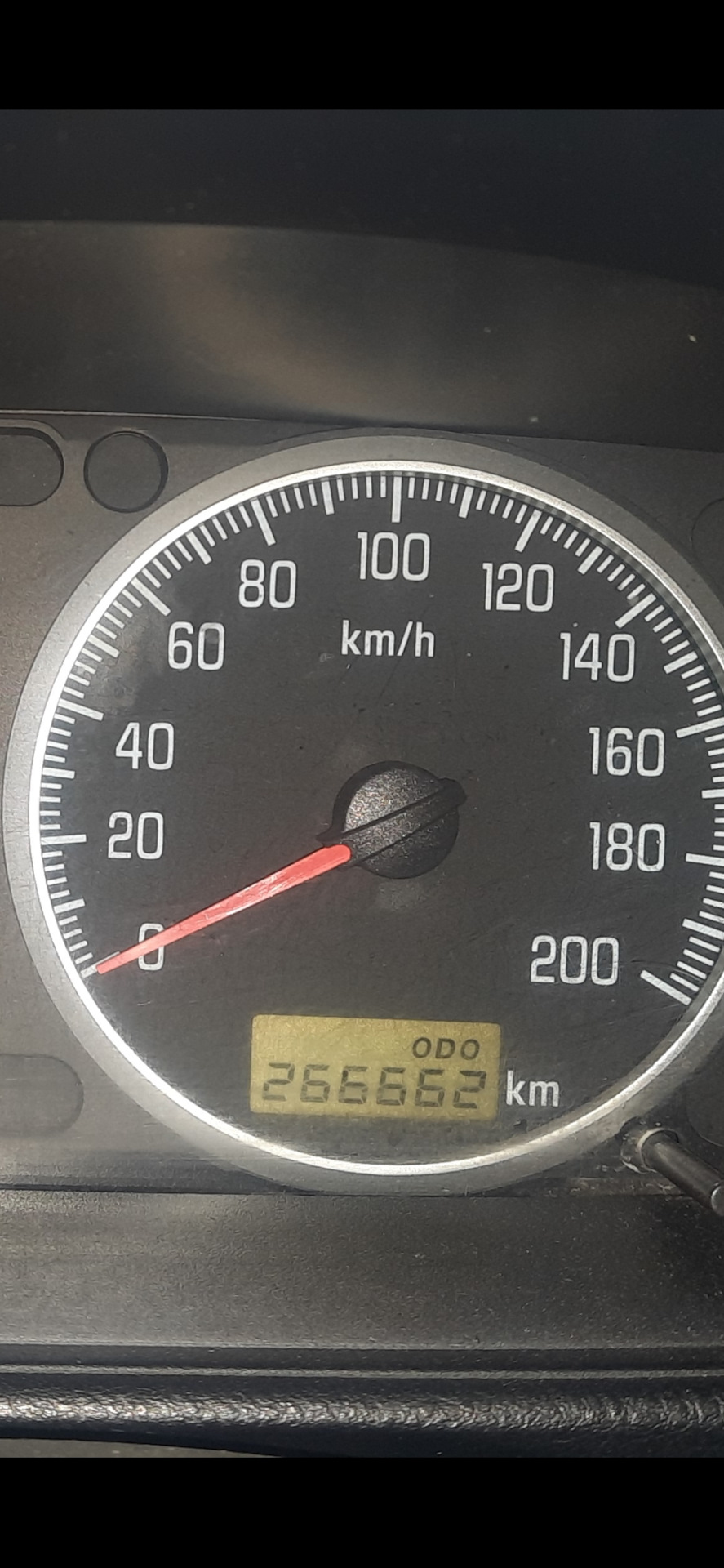
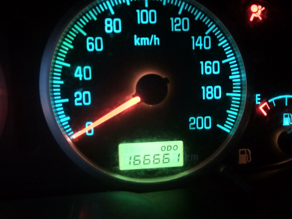
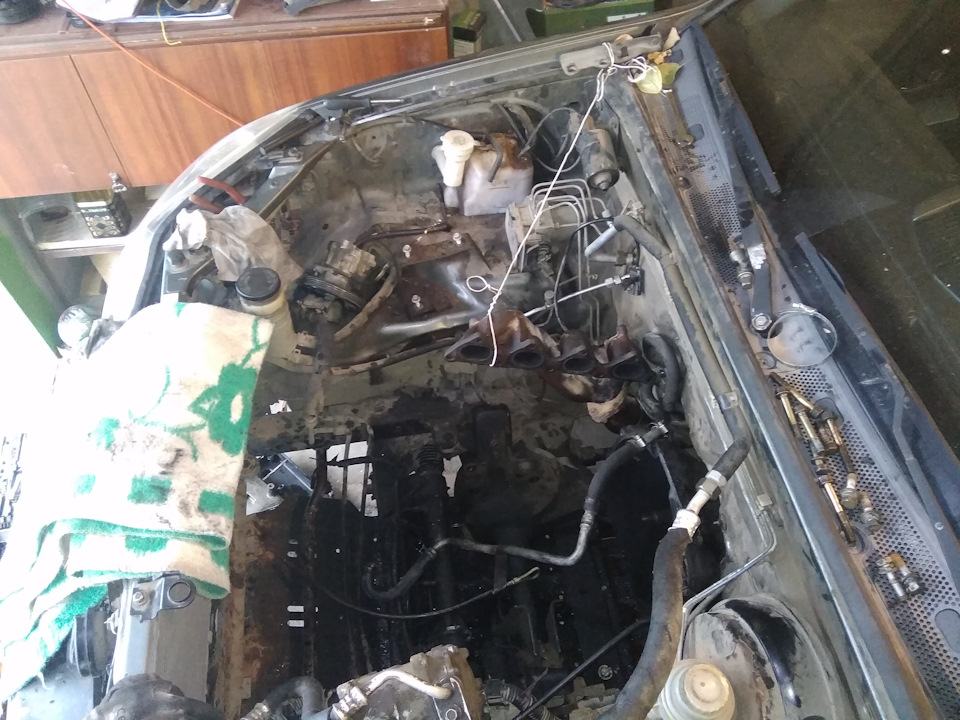
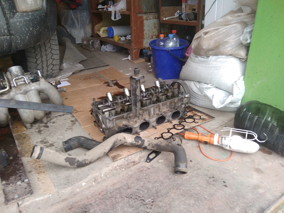
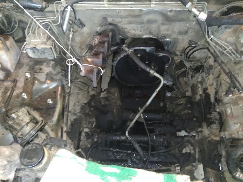
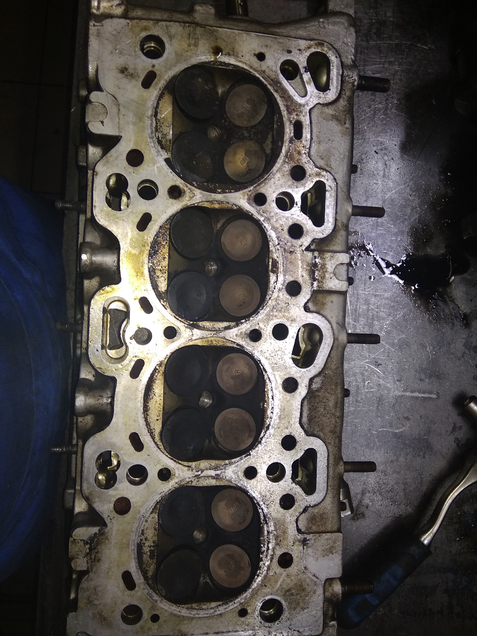
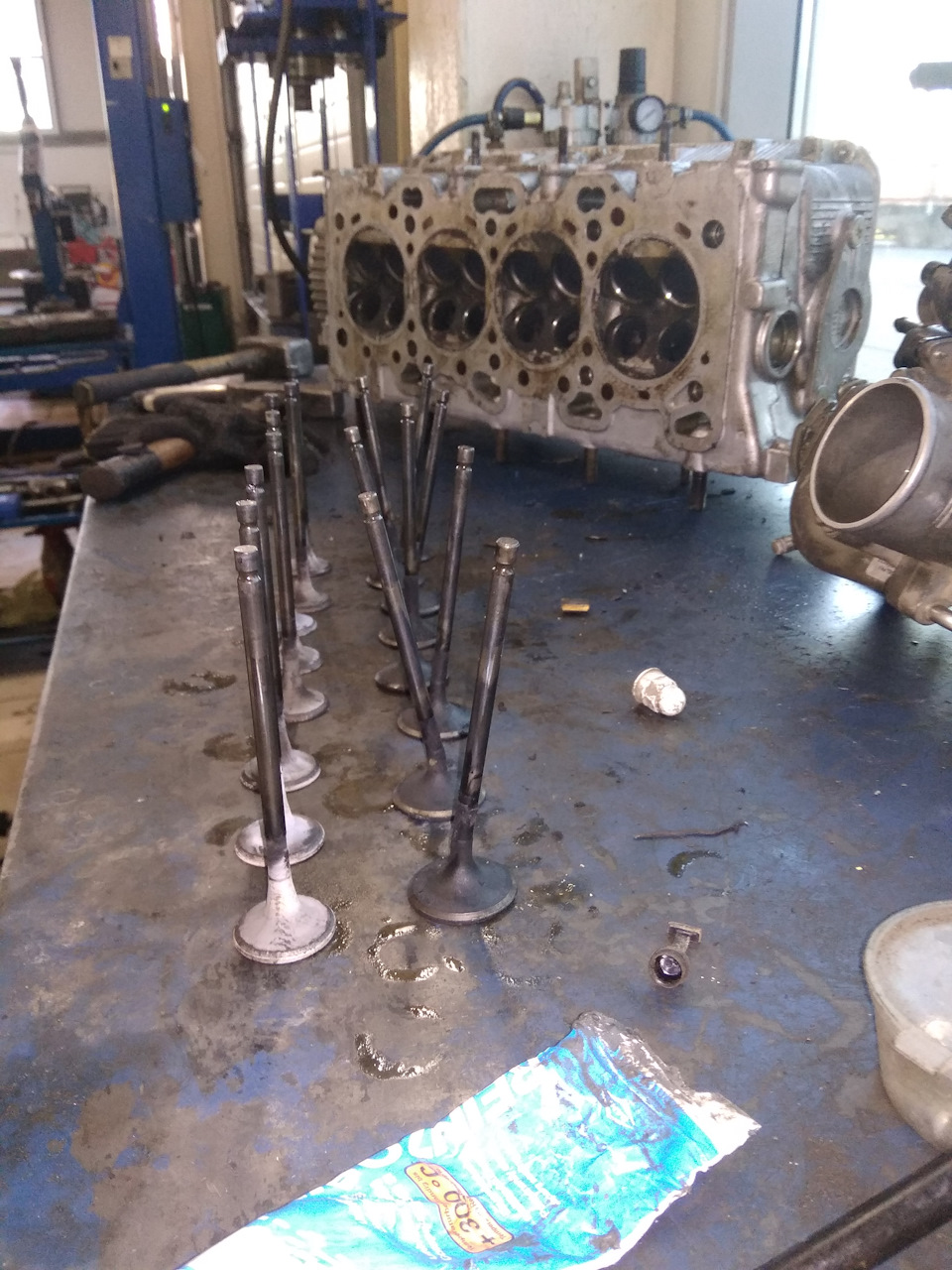
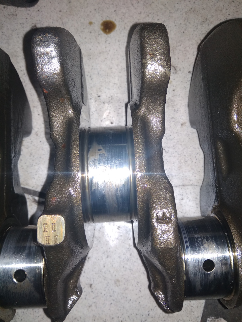
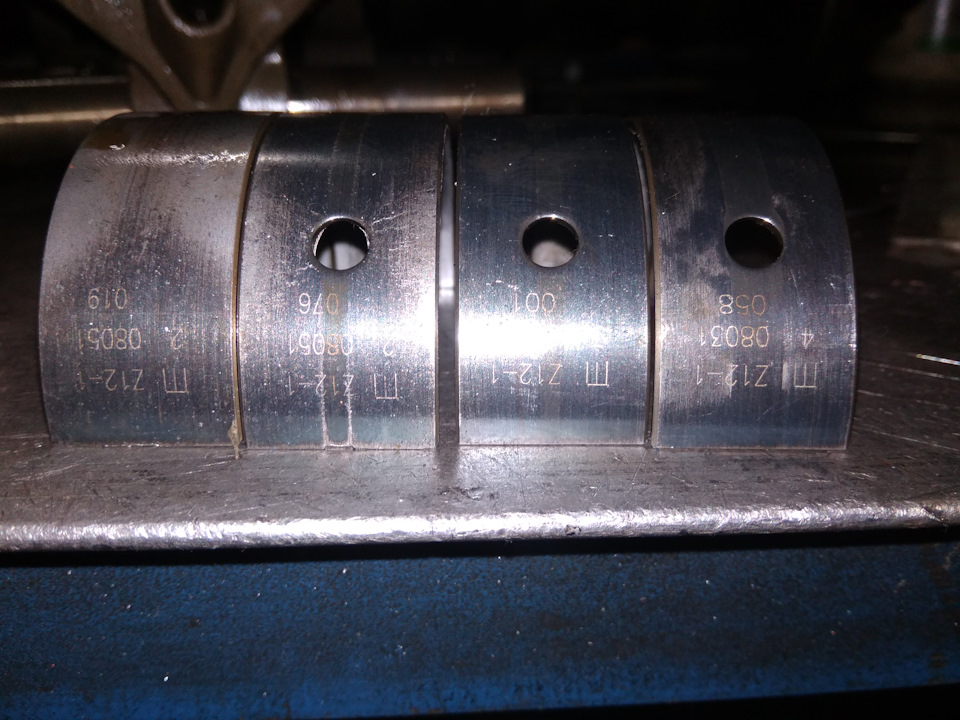
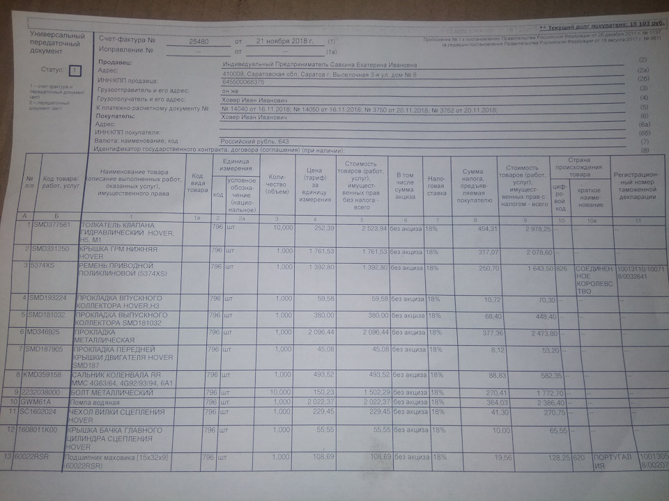
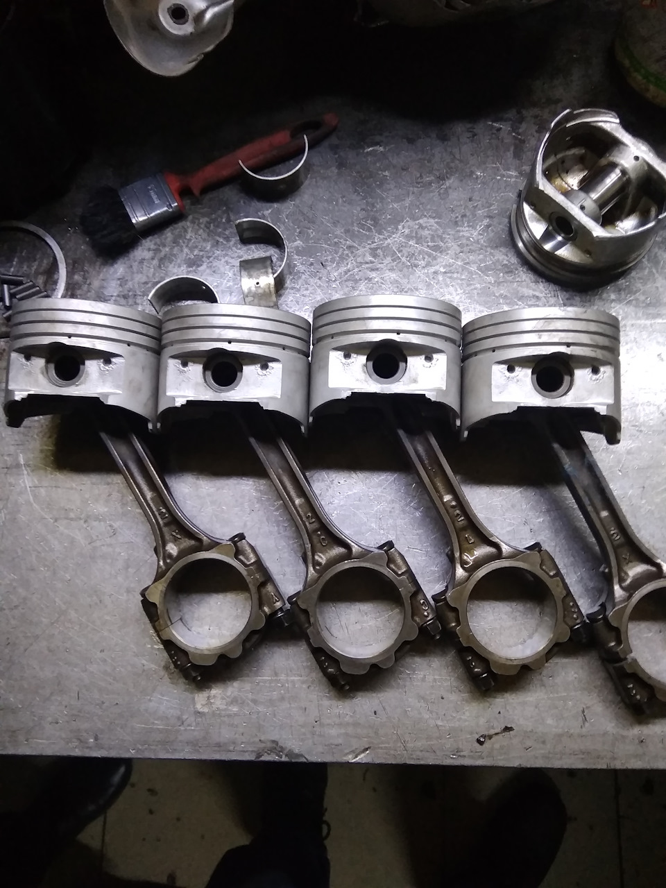
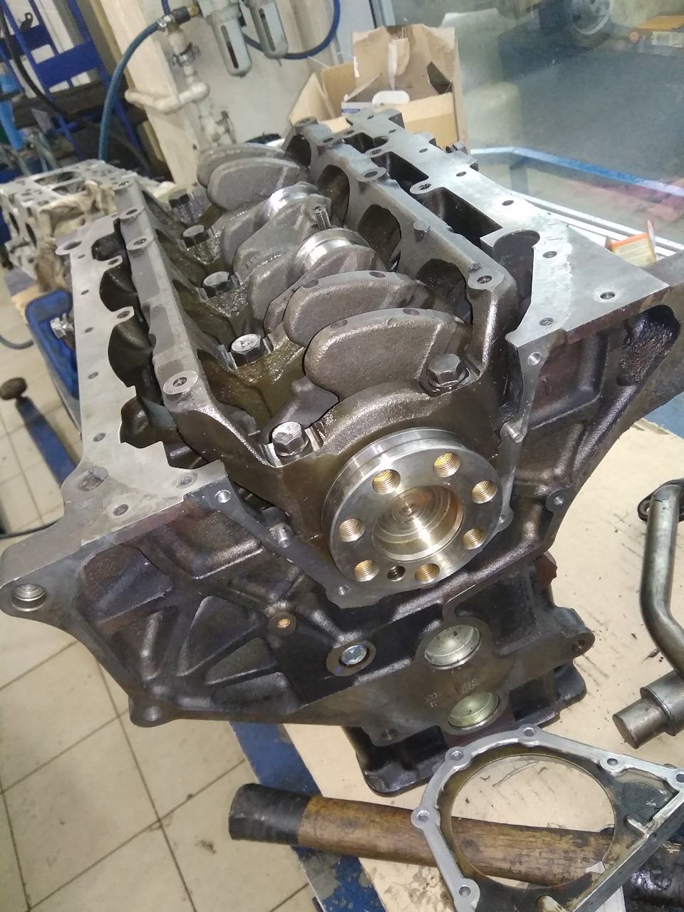
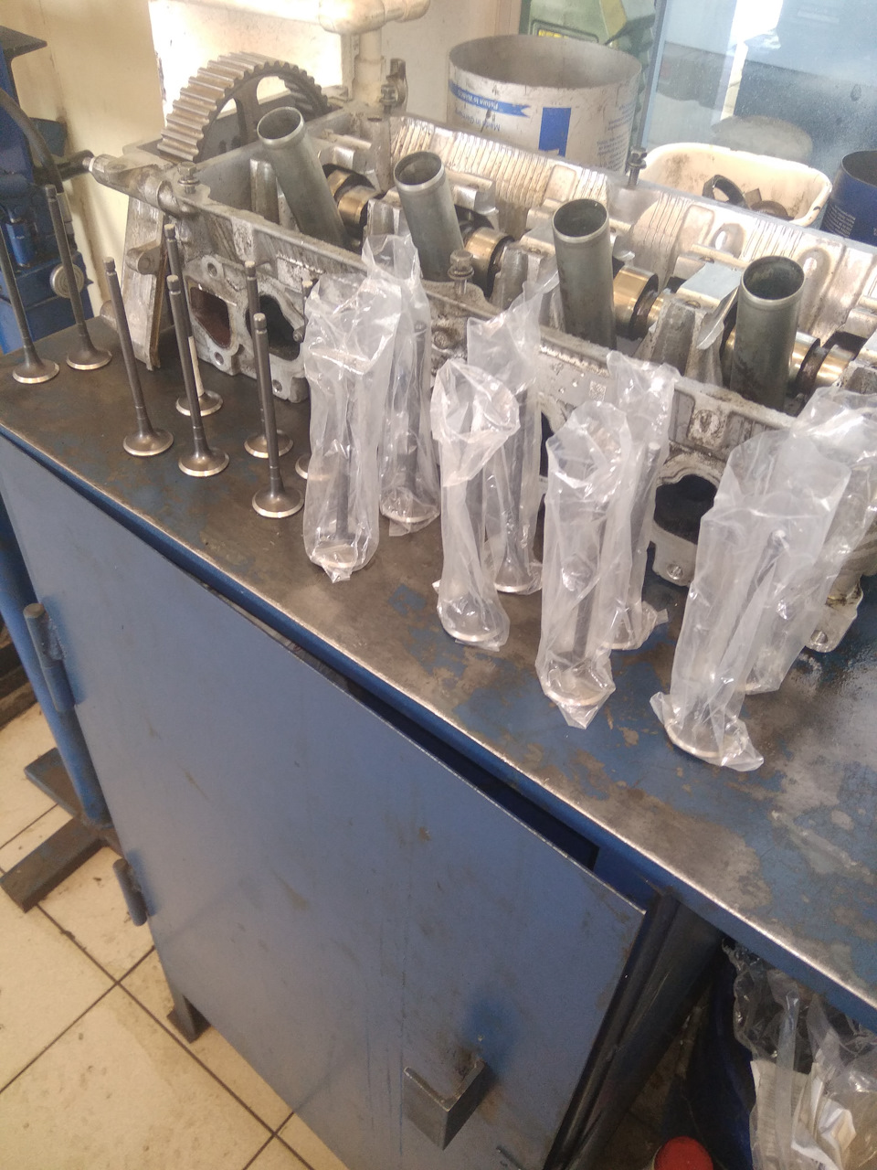
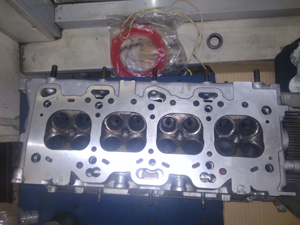
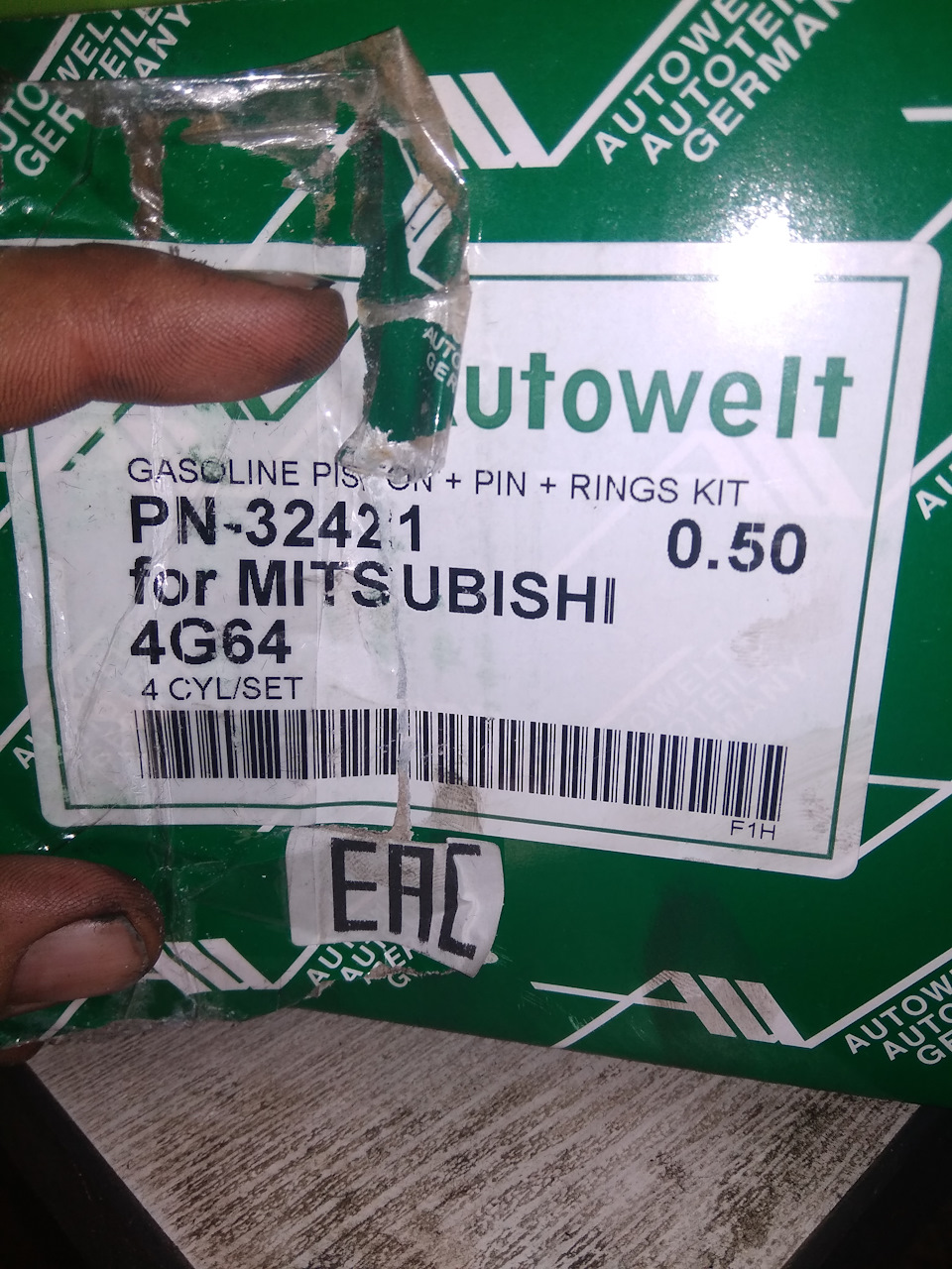
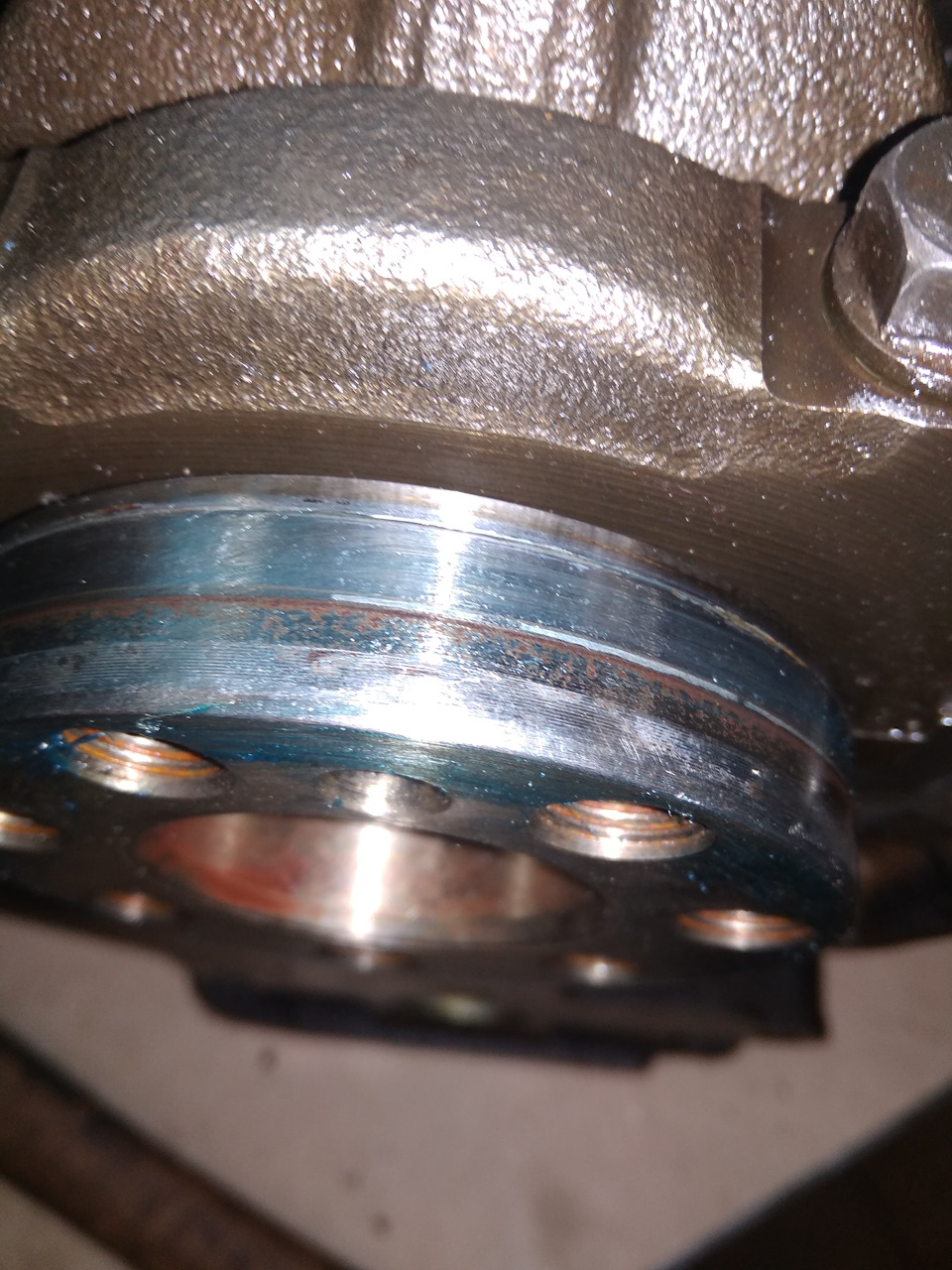
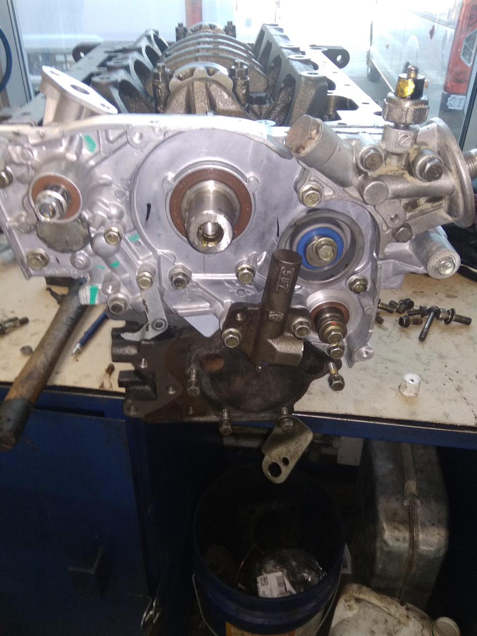
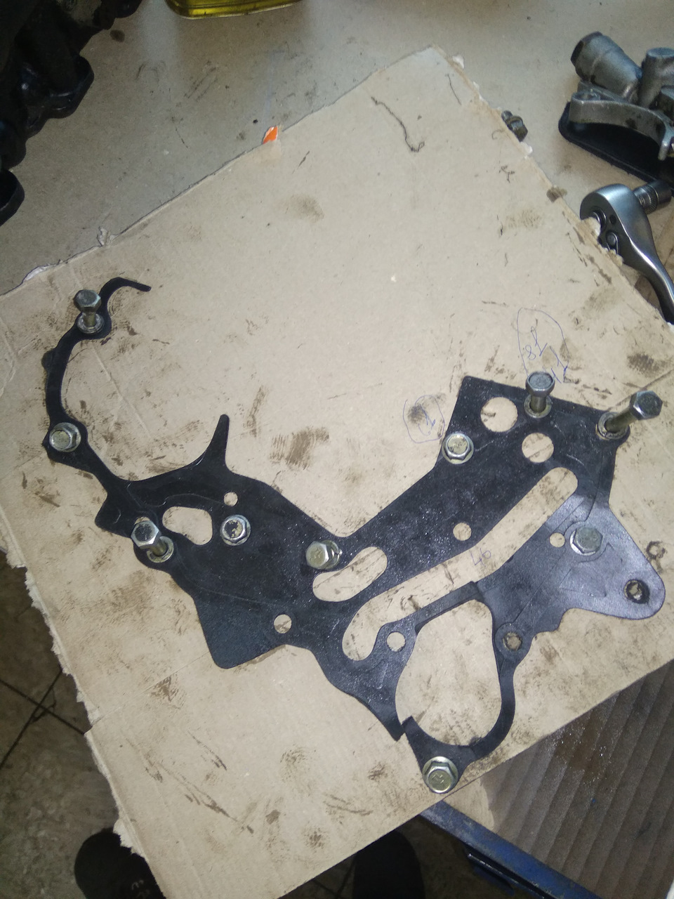
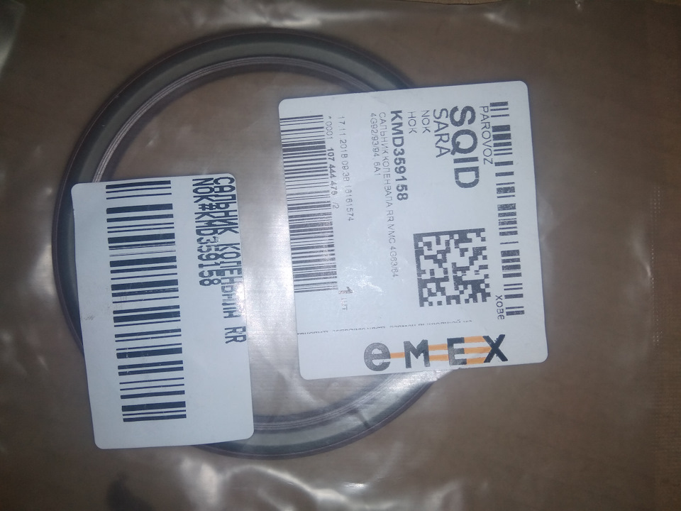
не знаю пришло время стечение обстоятельств(первая скорость, бордюр, старый натяжной) ну что есть то есть
Войдите или зарегистрируйтесь, чтобы писать комментарии, задавать вопросы и участвовать в обсуждении.
Только оригинальные руководства
Доступно сразу после оплаты
Полное соответствие бумажным изданиям
100% защита ваших оплат
Издательство: © «Монолит»
ISBN: 978-617-577-084-9-3
Количество страниц: 70
Формат: файл PDF
О руководстве
Тип двигателя: 4G64S4M
Объем двигателя: 2.4 л.
Мощность: 130 л.с.
В руководстве вы найдете
- руководство по ремонту двигателя 4G64S4M
- систему смазки двигателя 4G64S4M
- систему питания двигателя 4G64S4M
- систему управления двигателя 4G64S4M
В данной книге приводятся только описание ремонта двигателя 4G64S4M
Ознакомиться и купить полную книгу по ремонту автомобиля Great Wall Hover с 2005 года (включая ремонт двигателя) можно по ссылке
Содержание
Механическая часть двигателя
- Общие сведения
- Обслуживание на автомобиле
- Головка блока цилиндров
- Снятие и установка двигателя
- Блок цилиндров
- Привод газораспределительного механизма
- Приложение к главе
Система смазки
- Общие сведения
- Замена моторного масла и фильтра
- Снятие и установка масляного поддона (замена прокладки масляного поддона)
- Снятие и установка маслоприемника
- Датчик давления масла
- Приложение к главе
Система питания
- Общие сведения
- Сброс давления в системе питания
- Замена топливного фильтра
- Снятие и установка топливного бака
- Снятие и установка топливного модуля
- Топливная рампа в сборе с форсунками
- Снятие и установка адсорбера
- Приложение к главе
Система зажигания и управления двигателем
- Общие сведения
- Снятие и установка узла дроссельной заслонки
- Снятие и установка катушки зажигания с высоковольтными проводами
- Снятие и установка свечей зажигания
- Датчики системы управления (замена)
- Приложение к главе
Написать отзыв
Ваше Имя:
Ваш отзыв:
Оценка:
Отзывы покупателей
Автомобіль почав іноді гальмувати без натискання на педаль, у разі підвищення оборотів у роботі двигуна відбуваються провали. Проблема була у паливному фільтрі, замінив скориставшись цим керівництвом.
Доступно в форматах: EPUB | PDF | FB2
Страниц: 360
Год издания: 2013
Язык: Русский
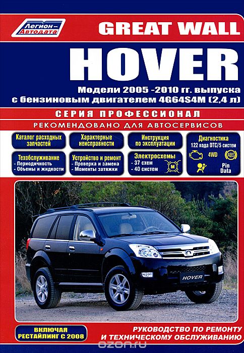
В руководстве дается пошаговое описание процедур по эксплуатации, ремонту и техническому обслуживанию полноприводных автомобилей Great Wall HOVER 2005-2010 гг. выпуска, оборудованных бензиновым двигателем 4G64S4M (2,4 л). Включены рестайлинговые модели с 2008 года. Издание содержит руководство по эксплуатации, подробные сведения по техническому обслуживанию автомобилей, диагностике, ремонту и регулировке элементов систем двигателя (в т.ч. системы впрыска топлива, снижения токсичности отработавших газов, зажигания, запуска и зарядки), элементов механических коробок передач (МКПП), раздаточной коробки (с механическим и электронным управлением, включая электронную систему управления), переднего редуктора, редуктора заднего моста, элементов тормозной системы (включая антиблокировочную систему тормозов (ABS), рулевого управления, подвески, кузовных элементов, систем кондиционирования и вентиляции. Приведены инструкции по диагностике 5 электронных систем: управления двигателем,…
Отзывы
 Валерия, Махачкала, 28.06.2017
Удобное пользование сайтом, большой каталог нехудожественной литературы. Нужна была книга «Great Wall HOVER. Модели 2005 -2010 гг. выпуска с бензиновым двигателем 4G64S4M (2,4 л). Руководство по ремонту и техническому обслуживанию (+ дисконтная карта в подарок)», нашла без проблем , скачала еще парочку похожих и читаю в свое удовольствие)))
 Тарас, Мариуполь, 28.02.2017
все ок, скачал прочитал. никаких проблем не возникло. Твердую 4+ сайт заслуживает
Те, кто смотрел эту страницу, также интересовались:
Часто задаваемые вопросы
1. Какой формат книги выбрать: PDF, EPUB или FB2?
Тут все зависит от ваших личных предпочтений. На сегодняшний день, каждый из этих типов книг можно открыть как
на компьютере, так и на смартфоне или планшете. Все скачанные с нашего сайта книги будут одинаково открываться
и выглядеть в любом из этих форматов. Если не знаете что выбрать, то для чтения на компьютере выбирайте PDF,
а для смартфона — EPUB.
2. Можно ли книги с вашего сайта читать на смартфоне?
Да. Как для iOS, так и для Android есть много удобных программ для чтения книг.
3. В какой программе открыть файл PDF?
Для открытия файла PDF Вы можете воспользоваться бесплатной программой Acrobat Reader. Она доступна для скачивания на сайте adobe.com
-
Contents
-
Table of Contents
-
Bookmarks
Quick Links
Related Manuals for Great Wall 4G64S4M
Summary of Contents for Great Wall 4G64S4M
-
Page 2
Preface This manual is specially made for those who GENERAL engage in automobile maintenance and repairing. Following general rules of system division of vehicles ENGINE (engine, clutch, etc.), this manual adopts the division methods by major assembly. In order to describe all parts belonging to an assembly, assemblies are further divided into several parts. -
Page 3
00-1 General Contents page Guide on Using the Manual ………. 00-3 Engine …………….00-5 Tightening Torque…………00-6 Sealant (FIPG) …………. 00-7… -
Page 4: Guide On Using The Manual
00-2 GENERAL GUIDE ON USING THE MANNUAL Guide on Using the Manual Grouping name Section Name Page Engine Front cover, Oil pump 11-33 Maintaining Steps Front Cover, Oil Pump (1) Profile plots are provided for you to Dismantling Steps: Corresponding number of parts to the Dismantling and Mounting understand the installation of each number in the figure of composing parts to show…
-
Page 5: Engine
00-5 OVERVIEW ENGINE ENGINE MODEL VEHICLE MODEL ENGINE MODEL DISPLACEMENT TYPE HOVER CUV 4G64-D-Y7 2,351 ML FOUR CYLINDERS, IN-LINE, SOHC…
-
Page 6: Tightening Torque
00-6 OVERVIEW TIGHTENING TORQUE Tightening Torque The common tightening torque is shown in the list. Tightening torque of special parts is shown at the beginning of each group. Tightening torque of bolts and nuts Torque (Kg. M) Diameter Thread Bolt (with spring washer) Valve bolt of bolt pitch…
-
Page 7: Sealant (Fipg)
00-7 OVERVIEW SEALANT(FIGP) Sealant (FIPG) Sealant is used on many parts of the engine and gearbox. The using of sealant is for the purpose of adequately sealing, therefore, much attention should be paid to the dosage, position and the surface of sealant. Insufficient dosage of sealant may result in leakage, while superfluous dosage of sealant may result in the overflow of sealant and jam the passage of water or oil, or narrow the passage.
-
Page 8: Table Of Contents
11-1 Engine Contents page General ……………. 11-2 Specifications …………… 11-3 Maintaining Standard ……….. 11-3 Tightening Torque …………11-5 Sealant …………….. 11-7 Special Tools…………..11-8 AC Generator and Ignition System ……11-11 Timing Toothed-belt …………. 11-14 Fuel System …………..11-23 Intake Manifold …………. 11-25 Exhaust Manifold and Water Pump……
-
Page 9: General
11-2 ENGINE SPECIFICATION General Specifications Items 4G64 S4 MPI Type In-line OHV, SOHC Number of Cylinders Combustion Chamber Single Pitch Roof Total Displacement ml 2,351 Cylinder Bore mm 86.5 Stroke mm 100.0 Compression Ratio 18 before top dead center Intake valve after bottom dead center Valve Timing before bottom dead center…
-
Page 10: Specifications
11-3 ENGINE SPECIFICATION Specifications Maintenance Standard Unit mm Items Standard Value Limit Value Generator Convex value of tensioner arm Toothed-belt Press-in value of tensioner arm (98~196N) Height of cam Air intake 37.39 36.89 Camshaft Air exhaust 36.83 36.33 Shaft diameter 45.0 Planeness of Bottom Surface 0.03…
-
Page 11
11-4 ENGINE SPECIFICATION Items Standard Value Limit Value Axial clearance 0.05 0.18 0.25 Main shaft diameter Crankshaft Connecting rod shaft diameter Radial clearance of main shaft 0.02 0.04 Planeness of top surface 0.05 * 0.2 Top surface lapping limit*Total lapping Cylinder Block of cylinder block and head Total Height… -
Page 12: Tightening Torque
11-5 ENGINE SPECIFICATION Tightening Torque Fastening Location Torque (Kg.M) Generator and Ignition System Fastening bolt of AC generator Stay bolt Pivot nut Crankshaft pulley bolt Spark plug Ignition coil bolt Timing toothed-belt Lower front cover of timing toothed-belt Tensioning pulley bolt Tensioning wheel arm bolt Automatic tensioning wheel bolt Central pulley bolt…
-
Page 13: Sealant
11-6 ENGINE SPECIFICATION Fastening Location Torque (Kg.M) Front cover and oil pump Oil drain plug Oil pan Oil suction filter bolt and nut Oil pressure switch Pressure relief plug Oil suction filter bracket bolt Front cover bolt Plug Flange bolt Oil pump cover bolt Oil pump cover screw Piston and connecting rod assembly…
-
Page 14: Special Tools
11-7 ENGINE SPECIAL TOOLS SPECIAL TOOLS Tools REF. NO. NAME PURPOSE Use MD998719 for Fastening CRANKSHAFT PULLEY MB990767 camshaft toothed-belt wheel WRENCH MB990938 HANDLE Use together with MD998776 Use MD998767 for timing MD990685 TORQUE WRENCH toothed-belt tensioning Disassembly and mounting of SCREW-PLUG front cover plug MD998162…
-
Page 15
11-8 ENGINE SPECIAL TOOLS Tools REF. NO. NAME PURPOSE MD998727 OIL PAN DETACHER Disassembly of oil pan BALANCING SHAFT Disassembly of reverse balanc- MD998371 BEARING PULLER ing shaft front bearing BALANCING SHAFT Disassembly of reverse bal- MD998372 BEARING PULLER ancing shaft rear bearing Disassembly and mounting of MD998772 VALVE SPRING… -
Page 16
11-9 ENGINE SPECIAL TOOLS Tools REF. NO. NAME PURPOSE Guide limit for disassembly and BALANCING SHAFT assembly of reverse balancing MB991603 BEARING PULLER shaft rear bearing (used with MD998372 together) CYLINDER HEAD BOLT Disassembly and mounting of MB991654 WRENCH cylinder head bolt Hydraulic lifter leakage-detect LEAKAGE-DETECTING MD998440… -
Page 17: Ac Generator And Ignition System
11-10 ENGINE AC GENERATOR AND IGNITIONSYSTEM AC GENERATOR AND IGNITION SYSTEM DISASSEMBLY AND MOUNTING 25N.m 23N.m 11N.m 23N.m 11N.m 25N.m Disassembly Procedure 1. driving belt 7. spark plug cable 2. water pump pulley 8. spark plug 3. power steering pump pulley 9.
-
Page 18
11-11 ENGINE TIMING TOOTHED-BELT NOTES FOR DISASSEMBLY DISASSEMBLY OF CRANKSHAFT BOLT MD998781 (1) Fasten flywheel with special tools (2) Disassemble crankshaft bolt. 9EN0268 NOTES FOR MOUNTING MOUNTING OF CRANKSHAFT BOLT MD998781 (1) Fasten flywheel with special tools. (2) Mount crankshaft bolt. 9EN0268 ADJUST DRIVING BELT TENSION TO STANDARD VALUE WITH DEFLECTION INDICATOR OR… -
Page 19: Timing Toothed-Belt
11-12 ENGINE TIMING TOOTHED-BELT TIMING TOOTHED-BELT DISASSEMBLY AND MOUNTING 11N.m 162N.m 48N. 48N. 24N. 54N. 8.8N.m 11N.m 35N. 22N. 6EN1769 Disassembly Procudure 1. front lower cover of timing thoothed-belt 11. crakshaft bolt** 12. crankshaft toothed-belt wheel 2. timing toothed-belt 3. temsioning pulley 13.
-
Page 20
11-13 ENGINE TIMING TOOTHED-BELT WHEEL NOTES FOR DISASSEMBLY DISASSEMBLY OF TIMING TOOTHED-BELT (1) Record the rotation direction of toothed-belt for correct re- mounting. Notes: Adhering of water or grease to the toothed-belt will sharply shorten its service life. So, after disassembly, try your best to avoid the toothed-belt, toothed-belt wheel and tensioner from 6EN0662 being contaminated and adhered by water or grease. -
Page 21
11-14 ENGINE TIMING TOOTHED-BELT WHEEL In case water or grease is found on these parts, check the front cover oil-seal, camshaft oil-seal and water pump to see if there exist leakage. MD998785 DISASSEMBLY OF BALANCING SHAFT TOOTHED- BELT WHEEL (1) Fasten balancing shaft toothed-belt wheel with the tools as shown in the figure. -
Page 22
11-15 ENGINE TIMING TOOTHED-BELT WHEEL (2) There are cracks on the surface of back rubber; cracks (3) There are cracks and peel-off on the surface of canvas (4) There are cracks at the bottom of the tooth (5) There are cracks on the side face of toothed-belt canvas peel-off side cracks crack at bottom of tooth… -
Page 23
11-16 ENGINE TIMING TOOTHED-BELT WHEEL (3) The overhang length of measuring rod. Replace if not conform 12mm to standard. Standard value 12mm 6EN0161 (4) Measure the amount of displacement while pressing down the 98~196N rod with a force of 98~196N. (5) Replace the automatic tensioner if the displacement of rod is at displacement least 1mm lesser than the value as measured in item (3). -
Page 24
11-17 ENGINE TIMING TOOTHED-BELT WHEEL TOOTHED-BELT WHEEL (1) Fixup balancing shaft toothed-belt wheel with the tools as shown in the figure. MD998785 (2) Tighten the bolt to the specified torque. 6EN0636 MOUNTING OF TIMING TOOTHED-BELT B (1) Align the marks of crankshaft toothed-belt wheel B and timing balancing toothed-belt wheel separately. -
Page 25
11-18 ENGINE TIMING TOOTHED-BELT TIGHTENING OF CRANKSHAFT BOLT (1) Fixup flywheel with special tools; (2) Mount crankshaft bolt. MD998781 6EN0634 MOUNTING OF OIL PUMP TOOTHED-BELT WHEEL (1) Insert cross point screwdriver into the plug hole on the left side of cylinder block to prevent balancing shaft from rotating. (2) Mount oil pump toothed-belt wheel. -
Page 26
11-19 ENGINE TIMING TOOTHED-BELT MOUNTING OF TIMING TOOTHED-BELT timing mark (1) Confirm the timing toothed-belt tensioner is properly mounted. (2) Align the timing mark on the camshaft toothed-belt wheel with the mark on the cylinder head. 6EN0673 (3) Align the timing mark on the crankshaft toothed-belt wheel with the mark on the front cover. -
Page 27
11-20 ENGINE TIMING TOOTHED-BELT (8) Verify that all timing marks are in a line. MD990685 MD998767 (9) Remove the screwdriver inserted at step (5) and mount the plug. (10) Turn camshaft 1/4 circle counter-clockwise, then turn it clock- wise until all timing marks come into line again. (11) Assemble the special tools socket wrench and torque wrench onto the tensioner pulley, then screw down the central bolt of tensioner pulley. -
Page 28: Fuel System
11-21 ENGINE FUEL OIL SYSTEM FUEL SYSTEM DISASSEMBLY AND MOUNTING 19N.m 20N.m 12N.m Notes for Mounting Disassembly Procedure Mounting of Fuel Distribution Assembly 1. water pipe Before mounting fuel distribution assembly, carefully 2. water pipe lubricate the matching face of the manifold or the O- 3.
-
Page 29: Intake Manifold
11-22 ENGINE INTAKE MANIFOLD INTAKE MANIFOLD DISASSEMBLY AND MOUNTING 19N.m 20N.m 20N.m 19N.m 13N.m 13N.m 30N.m Disassembly Procedure 1. engine Link Ring 2. engine Water Temperature Sensor 3. water Outlet 4. intake Manifold Bracket 5. intake manifold 6. intake Manifold Gasket NOTES FOR MOUNTING APPLICATION OF SEALANT FOR ENGINE WATER TEMPERATURE SENSOR…
-
Page 30: Exhaust Manifold And Water Pump
11-23 ENGINE EXHAUST MANIFOLD & WATER PUMP EXHAUST MANIFOLD, WATER PUMP DISASSEMBLY AND MOUNTING 45N.m 14N.m 29N.m 11N.m 24N.m 13N.m 49N.m 24N.m 24N.m 13N.m 14N.m Disassembly Procedure 11. water temperature sensing plug 1. oil level gauge 2. oil level gauge tube 12.
-
Page 31
11-24 ENGINE EXHAUST MANIFOLD & WATER PUMP NOTES FOR MOUNTING o-ring MOUNTING OF O RING SEAL (1) Wet O ring seal with water in order to assemble. Notes: There shouldn t be any oil or lubricating grease on the surface of O ring seal. -
Page 32: Rocker Arm And Camshaft
11-25 ENGINE ROCKER ARM AND CAMSHAFT ROCKER ARM AND CAMSHAFT DISASSEMBLY AND MOUNTING 3.9N.m 31N.m 18N.m Smear engine oil on all moving parts while mounting 6EN1762 1. air hose 12. A rocker arm A 2. PCV hose 13. B rocker arm B 3.
-
Page 33
11-26 ENGINE ROCKER ARM AND CAMSHAFT NOTES FOR DISASSEMBLY (1) Before disassemble the rocker arm and rocker shaft assembly, use the tools as shown in the figure to prevent hydraulic lifter from falling. MD998448 6AE0160 CHECK CAMSHAFT (1) Measure the height of camshaft Standard value and operating limit are as follows: Type Standard value… -
Page 34
11-27 ENGINE ROCKER ARM AND CAMSHAFT (3) Mount the special tool MD998441 onto the hydraulic lifter. MD998441 (4) Use the special tool MD998442 to lightly expel the steel ball inside the lifter and make it move 5-10 strokes until it can move smoothly. -
Page 35
11-28 ENGINE ROCKER ARM AND CAMSHAFT (9) Put the hydraulic lifter into vessel C, then use the special tool MD998442 MD998442 to lightly expel the steel ball inside the lifter. NOTES: Don t clean the hydraulic lifter in vessel C. Otherwise foreign body may enter the pressure chamber which is full of oil. -
Page 36
11-29 ENGINE ROCKER ARM AND CAMSHAFT (19) Take the hydraulic lifter out of the vessel, stick it up straight with its plunger at the top, stably impel the plunger until it can t move any more. Check and compare the height difference between the plunger and the new hydraulic lifter. -
Page 37: Cylinder Head And Valve
11-30 ENGINE CYLINDER HEAD AND VALVE CYLINDER HEAD AND VALVE DISASSEMBLY AND ASSEMBLY 78N.m thorough looseness 20N.m All parts inside should be coated with enging oil in assembly 6EN1386 Disassembly Procedure 1. cylinder head bolts 11. exhaust valve 2. cylinder head cluster 11.
-
Page 38
11-31 ENGINE CYLINDER HEAD AND VALVE Notices after Disassembly MB991654 The disassembled parts should be sorted as per the cylinder number and the intake/exhaust parts. Dismantle of Cylinder head Bolts (1) Loosen the bolts of each cylinder heads with SST. The looseness should be even and gradual. -
Page 39
11-32 ENGINE CYLINDER HEAD AND VALVE Mount of Valve Spring identifi cation upper site of (1) The valve spring shall be mounted in such way that the spring end spring with identification color faces the upper site of the valve spring. valve oil seal lower site of spring… -
Page 40
11-33 ENGINE CYLINDER HEAD AND VALVE (6) Mark a straight line with paint on the heads of cylinder head bolts and the cylinder head. (7) Tighten the cylinder head bolts by 90 in tightening order. (8) Tighten the bolts by another 90 , ensuring the paint marks on the heads of cylinder head bolts and the cylinder head should be in alignment. -
Page 41
11-34 ENGINE CYLINDER HEAD AND VALVE Valve Spring angle belwee cerrter line of spring and plun bine of subface (1) Measure the free spring height, in case it is less than the limit value, change the spring. Standard value: 51.0 mm Limit value: 50.0 mm free spring height (2) Measure the perpendicularity of the center line with the surface… -
Page 42
11-35 ENGINE CYLINDER HEAD AND VALVE Main Points in Change of Valve Seat (1) Cut out part of the valve seat to be changed so as to thin and remove it. cut out 1EN0274 (2) Trim the valve seat holes on the cylinder head as per the outside diameter of the enlarged valve seat. -
Page 43
11-36 ENGINE CYLINDER HEAD AND VALVE FRONT COVER, OIL PUMP, BALANCE SHAFT ,OIL PAN DISMANTLE AND ASSEMBLY 10N.m 1.0Kgft All inside parts should be coated with the engine oil 24N.m 2.4Kgifm 10N.m 19N.m 1.0Kgfm 1.9Kgifm 16N.m 1.7Kgfm 39N.m 4.0Kgfm 36N.m 3.7Kgfm 23N.m 2.4Kgfm… -
Page 44
11-37 ENGINE CYLINDER HEAD AND VALVE Main Points of Disassembly MD998727 Disassembly of Oil Sump Disassemble all of the bolts of oil sump. Tap the SST into the clearance between the cylinder block and the oil sump. Notice: Do not replace the SST with screwdriver or chisel, otherwise the oil sump will deform and leak oil. -
Page 45
11-38 ENGINE CYLINDER HEAD AND VALVE Disassembly of Rear Bearing of Balancing Shaft MB991603 (1) Tear down the rear bearing of the left balancing shaft from the cylinder block with SST. Remark:The SST (MB991603) should be mounted in front of the cylinder block when dismantling the rear bearing of the left balanc- ing shaft. -
Page 46
11-39 ENGINE CYLINDER HEAD AND VALVE Mount of Front Bearing of Balancing Shaft (1) Mount the front bearing with SST. MD998705 MD998705 bearing cylinderblock 6EN1035 Mount of Front Cover (1) Mount the SST on the front end of the crankshaft and coat the engine oil on the face of outer circumference of the SST, then mount on the front cover. -
Page 47
11-40 ENGINE CYLINDER HEAD AND VALVE Mount of Oil Seal of Lubricating Pump socket wrench (1) Press the oil seal into the front cover with the socket wrench. oil seal front cover Mount of Front Oil Seal of Crankshaft (1) Mount the front oil seal of crankshaft on the front cover with socket SST. -
Page 48
11-41 ENGINE CYLINDER HEAD AND VALVE (2) Tighten the flange bolt with specified torque and ensure the driven gear of oil pump is fastened on the left balancing shaft. 6EN0565 Mount of Plug MD998162 (1) Mount the new O-ring in the grooves at the front cover. (2) Mount the plug with SST and tighten it to the specified torque. -
Page 49: Piston And Connecting Rod
11-42 ENGINE CYLINDER HEAD AND VALVE Mount of Oil Filter bracket side (1) Clean the mounting face of the oil filter bracket. (2) Coat the engine oil on the O-ring of oil filter. (3) Screw in the oil filter, when the O-ring contacts the mounting face, screw another 3/4 round (tightening moment: 1.4 kg.m) 6EN0591 Inspection…
-
Page 50: Disassembly And Assembly
11-43 ENGINE CYLINDER HEAD AND VALVE DISASSEMBLY AND ASSEMBLY All inside parts must be coated with engine oil 6EN0526 Disassembly Procedure 1. connecting rod nut 2. connecting rod cap 3. connecting rod bearing 4. piston and connecting rod cluster 5. connecting rod bearing 6.
-
Page 51
11-44 ENGINE CYLINDER HEAD AND VALVE Main Points in Disassembly Disassembly of Connecting Rod Cap (1) Mark the cylinder No. on the side face of the larger end of the cylinder No. connecting rod so as to ensure the correct assembly. (2) Put aside the dismantled connecting rod, connecting rod cap and connecting rod bearing in order as per the cylinder No. -
Page 52
11-45 ENGINE CYLINDER HEAD AND VALVE Main Points for Mount piston Mount of Piston Pin (1) Measure the following dimensions of the piston, piston pin and connecting rod; A) Length of inserting hole of the piston pin; B) Width between the keyway C) Length of piston pin D) Width of smaller end of connecting rod. -
Page 53
11-46 ENGINE CYLINDER HEAD AND VALVE (10) Check whether the piston can rotate freely. 6EN0 298 Mount of oil ring upper scraper blade (1) Put the main ring of oil ring in the oil ring groove. main ring Remark: 1. The scraper blade and the main ring has the specified upper./lower lower scraper blade face. -
Page 54
11-47 ENGINE CYLINDER HEAD AND VALVE Mount of Piston and Connecting Rod Cluster upper scraper blade (1) Coat enough engine oil on the piston, air ring and oil ring. (2) Adjust the openings of the air ring and oil ring (scraper blade and the main ring) to the place shown in the figure. -
Page 55
11-48 ENGINE CYLINDER HEAD AND VALVE Mount of Connecting Rod Cap (1) When mounting the connecting rod cap, align the marks made in disassembly well, if mounting the new member without cylinder No. mark, the anti-rotary gap shown in the figure should be mounted at the same side anti-rotary gap DEN0051… -
Page 56
11-49 ENGINE CYLINDER HEAD AND VALVE Inspection Piston Ring (1) Check whether the piston ring has damage, over abrasion or breakage, if it has, change it, in the case of changing the piston, the piston ring needs to be changed too. (2) Check the clearance between the piston ring and the piston ring groove, if it is over large, change the piston ring or the both parts. -
Page 57: Crankshaft, Cylinder Block And Flywheel
11-50 ENGINE CYLINDER HEAD AND VALVE CRANKSHAFT, CYLINDER BLOCK AND FLYWHEEL DISASSEMBLY AND ASSEMBLY 132N.m 11N.m 11N.m 8.8N.m Smear the engine oil on all moving parts 25N.m+90 ~100 Disassembly Procedure 1. flywheel bolt 8. main bearing cap 2. flywheel 9. low bearing of crankshaft 3.
-
Page 58: Cylinder Block
11-51 ENGINE CYLINDER HEAD AND VALVE Inspection clearance gauge of Measurement for Crankshaft Play (clearance gauge of plastic plastic cord cord) (1) Clean the oil on the main journal and the inner race of bearing. (2) Mount the crankshaft. (3) Cut the clearance gauge of plastic cord in the length that is the same with the width of bearing, then put them on the crankshaft 6EN0703 journal and ensure them are parallel with the axial center line.
-
Page 59
11-52 ENGINE CYLINDER HEAD AND VALVE Re-boring of Cylinder Diameter (1) The diameter for the enlarged piston should be determined according to the max cylinder diameter. Identification of piston diameter dimension Identification mark thrusting Plus 0.50 0.50 direction Plus 1.00 1.00 piston diameter Remark: Dimension mark is printed on the top of piston. -
Page 60
11-53 ENGINE CYLINDER HEAD AND VALVE Mount of crankshaft bearing (1) Select the bearing that meets the dimension of crankshaft main No.3 journal as per the form below. No.2 Combination of crankshaft main journal and Identification main shaft aperture No.4 I d e n t i f i c a t i o n marks and marks and colors… -
Page 61
11-54 ENGINE CYLINDER HEAD AND VALVE Mount of Main Bearing Cap/ Main Bearing Bolt (1) Mount the main bearing cap with the arrow mark thereof directing to the side of timing toothed belt. (2) Be sure the length of bolt is less than the limit value before mounting the main bearing cap bolt. -
Page 62
11-55 ENGINE CYLINDER HEAD AND VALVE Mount of Oil Seal MD990938 MD998376 6EN0709 Mount of Rear Oil Seal Cover Specified sealant Brand: Genuine Mitsubishi brand sealant MD970389 or the equivalents. Notice: (1) The rear oil seal cover should be mounted quickly on the condition the sealant is not dry ( 15 min). -
Page 63: Ac Generator
11-56 ENGINE AC GENERATOR AC GENERATOR DISASSEMBLY AND ASSEMBLY 9EN0187 Disassembly Procedure 1. generator pulley 2. rotor assembly 3. rear bearing 4. bearing block 5. front bearing 6. front cap 7. stator assembly 8. retaining plate 9. adjustor and brush stand 10.
-
Page 64
11-57 ENGINE AC GENERATOR NOTES FOR DISASSEMBLY SEPARATION OF STATOR AND FRONT CAP (1) Insert the screwdriver into the gap between front cap and stator to separate the front cap from the stator. (2) If it is hard to separate them, lightly hit the front cap with a plastic hammer and prize it with screwdriver at the same time. -
Page 65
11-58 ENGINE AC GENERATOR STATOR (1) Conduct on stator examination over the stator and confirm whether the conduction exists with the lead-wire of the winding, if not, replace the stator assembly. 3EN0208 (2) Check the grounding of stator winding. Confirm whether con- duction exists between the winding and stator iron core, if yes, replace the stator assembly. -
Page 66
11-59 ENGINE AC GENERATOR BRUSH (1) If the brush is worn out to the wear limit line, replace brush by taking the following steps: wear limit line wite 9EN0192 (2) The brush may be taken off by burning off the soldering joint of the brush lead-wire. -
Page 67: Starter
11-60 ENGINE STARTER STARTER DISASS0.EMBLY AND ASSEMBLY 6EN1412 Disassembly Process 1. bolt 12. washer B 2. magnet valve 13. plate 3. bolt 14. ball 4. bolt 15. planetary gear 5. rear carrier 16. rod 6. brush holder 17. snap spring 7.
-
Page 68
11-61 ENGINE STARTER magnetic switch terminal S ESSENTIALS FOR DISASSEMBLY DISASSEMBLY OF MAGNET VALVE terminal B (1) Knock down exciting coil from terminal M of the magnet valve. terminal exciting coil wiring 6EN0616 DISASSEMBLY OF ROTOR AND BALL casing tube (1) Do not drop the ball mounted on the end of bearing while disassemble the rotor. -
Page 69
11-62 ENGINE STARTER (2) Check the outside diameter of the . commutator Standard value: 29.4mm Limit value: 28.4mm 1EN0298 depth (3) Check the drop depth of mica between commutator separators. Standard value: 0.5mm brush holder mica Limit value: 0.2mm 1EN0296 BRUSH HOLDER (1) Check whether conduction exists between brush holder plate and brush holder, if not, it is normal. -
Page 70
11-63 ENGINE STARTER (3) While crumbing worn battery with a plier, be careful not to new brush damage the soft pigtail. soft pigtail sodering (no (4) In order to make soldering tin easy to be adhered, scrape the soft soldering tin pigtail end with a piece of sand paper. -
Page 71: Throttle Body
11-64 ENGINE THROTTLE BODY THROTTLE BODDY DISASSEMBLY AND ASSEMBLY 2.9N.m 3.4N.m 3.4N.m 4.9N.m 6EN1782 Disassembly Procedure 1. holder 2. throttle position transducer 3. idle air valve 4. o-ring 5. throttle body 6. SAS speed adjusting screw SAS Remarks 1. SAS has been adjusted before leaving factory, so no adjustment is needed.
Chery Tiggo Tingo ЧЕРНАЯ КОШЕЧКА!!!
Руководство по ремонту Чери ТИГО

OLESSIA
Была больше месяца назад
Леся Ясинская, 38 лет
Я езжу на Geely Atlas 2.4, 4*4 и Hyundai Santa Fe (до этого — 4 машины)
Нижневартовск, Россия

Руководство по ремонту, техническому обслуживанию и эксплуатации автомобиля Chery Tiggo, с бензиновыми двигателями S0R481FC (1,8), 4G63S4M (2,0) и 4G64S4M (2,4) литра. В формате pdf (FineReader).
Ссылка: vk.com/doc-34239085_50978…9?hash=1faa59e66c08beeef1

3 февраля 2014
Метки: плановое ТО
Ранее Руководство по ремонту Чери ТИГО
Далее Тюнинг салона (в скором будущем)
Разместить рекламу
Реклама
Машины в продаже

Волгоград
Chery Tiggo 3, 2017
849 000 ₽

Таганрог
Chery Tiggo 3, 2017
949 000 ₽

Волгоград
Chery Tiggo 3, 2018
875 000 ₽

Краснодар
Chery Tiggo 3, 2018
1 220 000 ₽
Посмотреть больше машин на Дроме
Комментарии
11
Войдите или зарегистрируйтесь, чтобы писать комментарии, задавать вопросы и участвовать в обсуждении.
Войти
Зарегистрироваться

Pavel2624
Я езжу на Chery Tiggo
9 месяцев

koshmin
Я езжу на Aston Martin V8 Coupe
Спасибо!Здесь получше качество.
static.e92.ru/upload/file…TIGGO%20%D1%81%202005.pdf
2 года

tyapa38
Я езжу на KIA Sportage (1G)
вот Человечище, низкий поклон, пусть у тебя все сбывается.
1 год

megashaitan
Я езжу на Chery Tiggo
Да хранит тебя господь . Ныне и присно и во веки веков. Аминь.
2 года

Rost36ru
Я езжу на Honda Stepwgn (5G)
Спасибо. Очень хорошая книга, много правильных советов.

Спасибо тебе добрый человек затыкался в инете искать эту книгу(
8 лет

пожалуйста)
8 лет

Aleks261
Я езжу на KIA Carnival (2G)
Спасибо! Подпись.
8 лет

СПАСИБОЧКИ!

fox6
Я езжу на Haval H6 (1G)
Спасиба, скачал, пригодится
9 лет

Пожалуйста))) очень рада помочь)
9 лет
Preface
This manual is specially made for those who
engage in automobile maintenance and repairing.
Following general rules of system division of vehicles
(engine, clutch, etc.), this manual adopts the division
methods by major assembly. In order to describe all
parts belonging to an assembly, assemblies are further
divided into several parts.
Brief introductions, specifications, main points
of adjustments, mounting and dismounting,
assembling and disassembling of the assembly
components are covered in this manual. On the top of
the first page of all assemblies are the content, through
which the needed information can be easily found.
All explanations and specifications in this
manual is the latest till the date of printing.
GENERAL
00
ENGINE
11
————————————————————————————————————————————————————-
00-1
page
Guide on Using the Manual …………………………………… 00-3
Engine ……………………………………………………………….. 00-5
Tightening Torque………………………………………………… 00-6
Sealant (FIPG) ……………………………………………………. 00-7
General
Contents
00
————————————————————————————————————————————————————-

00-2
1. oil filter
2. oil drain plug
3. oil plug washer
4. oil pan
5. oil filter screen
6. oil filter screen washer
7. overflow valve plug
8. overflow valve string
9. overflow valve core
10. oil seal
11. oil pump shell
12. O-ring
13. oil pump shell cover
14. outer rotor
15. inner rotor
Dismantle steps:
Guide on Using the Manual
Maintaining Steps
(1)
Profile plots are provided for you to
understand the installation of each
component.
(2)
Use reference number of the parts to
show operation steps, mark the parts
that can not be used repeatedly (marked
as
) and the tightening torque.
Lubricating grease
[Means all-purpose lubricating grease if not
specially indicated otherwise.]
Sealant or adhesive
Engine oil or gear oil
Division of Notes for Maintaining
When there are notes for maintaining, stan-
dard value and usage of special tools, de-
tailed explanation is given.
Marks for Lubricant, Sealant and
Adhesive
Indicate in the figure of composing parts the
location where lubricant, smearing or sup-
plying of sealant and adhesive are to be
applied.
Dismantling Steps: Corresponding number of parts to the
number in the figure of composing parts to show
the dismantling steps.
Disassembly Steps: Corresponding number of parts to the
number in the figure of composing parts to show
the disassembly steps.
Mounting Steps: Mounting steps should be indicated when the
mounting may not in the reverse order with
dismantling steps. Otherwise, the mounting steps
can be omitted.
Assembly Steps: Mounting steps should be indicated when the
mounting may not in the reverse order with
dismantling steps. Otherwise, the mounting steps
can be omitted.
N
Indicates Notes for dismantling or disassembly
available.
Indicates Notes for mounting or assembly
available.
Grouping name
Section Name Page
Engine
Front cover, Oil pump
11-33
Front Cover, Oil Pump
Dismantling and Mounting
Stands for part that may not
be used repeatedly
stands for tightening torque
These numbers are corresponding to the
numbers in the steps of dismantling,
disassembly, mounting and assembly.
9EN0040
GENERAL
GUIDE ON USING THE MANNUAL
Explanations are given for the
maintaining essentials and
notes for dismantling and
mounting, disassembly and
assembly.
These English letters corresponds to the
letters in the steps of dismantling,
mounting, disassembly and assembly.
1
13
14
15
12
11
10
1.4Kg.m
9
8
7
4.5Kg.m
1.9
Kg.m
5
6
1
N
N
Smear the engine oil on all the
movement parts while assembling
E
D
A
C
B
B
A
B
A
A
MD998727
MD998727
DILD583
DILD584
Disassembly notes:
Oil pan disassembly
After you take down the bolt , disassembly the oil pan with
special tool.
A
A
————————————————————————————————————————————————————-

00-5
VEHICLE MODEL
ENGINE
MODEL
DISPLACEMENT
TYPE
HOVER CUV
4G64-D-Y7
2,351 ML
FOUR CYLINDERS, IN-LINE, SOHC
ENGINE MODEL
OVERVIEW
ENGINE
————————————————————————————————————————————————————-

00-6
OVERVIEW
TIGHTENING TORQUE
Tightening Torque
The common tightening torque is shown in the list.
Tightening torque of special parts is shown at the beginning of each group.
Tightening torque of bolts and nuts
Thread Dimension
Torque (Kg. M)
Light alloy
Cast iron, steel
NPTF
1/16
0.5
0.8
0.8
1.2
PT
1/8
0.8
1.2
1.5
2.2
PT
1/4
2.0
3.0
3.5
4.5
NPTF
1/4
2.0
3.0
3.5
4.5
PT
3/8
4.0
5.5
5.5
7.5
PT
1/2
7.0
10.0
12.0
16.0
Tightening torque of taper thread
Torque (Kg. M)
Bolt (with spring washer)
Valve bolt
Head mark 4
Head mark 7
Head mark 10
Head mark 4
Head mark 7
M6
1.0
0.9
1.3
1.1
M8
1.25
1.1
1.8
3.0
1.4
2.4
M10
1.25
2.0
3.4
6.0
3.0
5.0
M12
1.25
3.6
6.2
10.8
5.5
9.0
Diameter
of bolt
Thread
pitch
————————————————————————————————————————————————————-
00-7
Sealant (FIPG)
Sealant is used on many parts of the engine and gearbox. The using of sealant is for the purpose of adequately sealing,
therefore, much attention should be paid to the dosage, position and the surface of sealant. Insufficient dosage of sealant
may result in leakage, while superfluous dosage of sealant may result in the overflow of sealant and jam the passage of
water or oil, or narrow the passage. So, in order to avoid leaking on the mounting surface, it is absolutely necessary to
keep the correct dosage that may keep from disconnection.
FIPG used in the engine is of Room Temperature Vulcanizing (RTV) and is provided in the way of 100-gram tube (Piece
No. MD970389, for engine use). RTV may vulcanize after reaction with the water content in the air; therefore, it is usually
used on the metal end face.
Disassembly
Components assembled with sealant may be disassembled without using a special method. However, in some cases, it
is necessary to lightly hit the components with a mallet or similar tools so as to break sealant on the coupling face, or
use a smooth thin sealant knife to hit into the joint face gently without damaging the coupling face. When dismounting
the engine oil pan, use special tool for dismounting oil pan (MD998727).
Cleaning of Sealing Surfaces
Remove rubbish on the sealing surface with a sealant knife or a steel wire brush. Be sure the sealing surface is flat and
smooth, and there isn
t any oil stain of foreign object on it. Remember to remove the sealant inside the mounting hole
and the threaded holes.
Essentials for Smearing
Matters to be taken into consideration while assembling components with FIPG.
Smear sealant equally within the prescribed diameter to cover around the mounting hole. Sealant that is not yet vulcanized
can be removed. After the installation, the sealant should be sufficiently vulcanized (approximately 1 hour or so). Do
not apply oil on the smeared part or wet or startup the engine during this period.
OVERVIEW
SEALANT(FIGP)
————————————————————————————————————————————————————-
11-1
page
General ……………………………………………………………… 11-2
Specifications ……………………………………………………… 11-3
Maintaining Standard …………………………………………… 11-3
Tightening Torque ……………………………………………….. 11-5
Sealant ………………………………………………………………. 11-7
Special Tools………………………………………………………. 11-8
AC Generator and Ignition System ………………………… 11-11
Timing Toothed-belt …………………………………………….. 11-14
Fuel System ……………………………………………………….. 11-23
Intake Manifold ……………………………………………………. 11-25
Exhaust Manifold and Water Pump ………………………… 11-26
Rocker Arm and Camshaft ……………………………………. 11-28
Cylinder Head and Valve ……………………………………… 11-34
Front Cover and Oil Pump ……………………………………. 11-40
Piston and Connecting Rod ………………………………….. 11-49
Crankshaft, Cylinder Block and Flywheel ………………… 11-55
AC Generator ……………………………………………………… 11-62
Starter ……………………………………………………………….. 11-66
Throttle Body ………………………………………………………. 11-70
Engine
Contents
11
————————————————————————————————————————————————————-

11-2
Specifications
4G64 S4 MPI
Type
In-line OHV, SOHC
Number of Cylinders
4
Combustion Chamber
Single Pitch Roof
Total Displacement
ml
2,351
Cylinder Bore
mm
86.5
Stroke
mm
100.0
Compression Ratio
9.5
Intake valve
On
18
before top dead center
Valve Timing
Off
53
after bottom dead center
Exhaust valve
On
50
before bottom dead center
Off
18
after top dead center
Lubrication system
Compression supply, full flow filtering
Type of oil pump
Gear type
Cooling system
Water cooling forced circulation
Type of water pump
Centrifugal impeller
ENGINE
SPECIFICATION
General
Items
————————————————————————————————————————————————————-

11-3
ENGINE
SPECIFICATION
Specifications
Maintenance Standard
Unit
mm
Items
Standard Value
Limit Value
Convex value of tensioner arm
12
Press-in value of tensioner arm (98~196N)
1
Height of cam
Air intake
37.39
36.89
Camshaft
Air exhaust
36.83
36.33
Shaft diameter
45.0
Planeness of Bottom Surface
0.03
0.2
Cylinder Head
Surface lapping limit*Total lapping of cylinder block and head
* 0.2
Total height
119.9
120.1
Length of cylinder head bol
97.4
99.4
Edge thickness
Intake
1.0
0.5
Exhaust
1.2
0.7
Diameter of valve stem
6.0
Valve
Intake
0.02
0.05
0.10
Exhaust
0.03
0.07
0.15
Inclination
45
45.5
Height
Intake
112.30
111.80
Exhaust
114.11
113.61
Free Height
51.0
50.0
Valve Spring
Working pre-tightening force/Working depth Kg/mm
27.2/44.2
Verticality
2
4
Contact width
0.9
1.3
Minor diameter
6.0
Valve Guide
Major diameter
11.0
Indentation depth
14.0
Convex value of valve stem
49.3
49.8
Oil Pump
Lateral clearance
Driving gear
0.08
0.14
Driven gear
0.06
0.12
Piston
Piston clearance
0.02
0.04
Lateral clearance
Ring No.1
0.02
0.06
0.1
Ring No.2
0.02
0.06
0.1
Piston Ring
Ring No.1
0.25
0.35
0.8
End clearance
Ring No.2
0.40
0.55
0.8
Oil control ring
0.10
0.40
1.0
Major diameter
22.0
Piston Pin
Indentation force Kg.
755
1750
Indentation temperature
Room temperature
Crankshaft
Internal clearance of crankshaft pin
0.02
0.05
0.1
Connecting Rod
Lateral clearance on big end
0.10
0.25
0.4
Generator
Toothed-belt
Radial clearance between valve
stem and valve guide
————————————————————————————————————————————————————-

11-4
Items
Standard Value
Limit Value
Axial clearance
0.05
0.18
0.25
Crankshaft
Main shaft diameter
57
Connecting rod shaft diameter
45
Radial clearance of main shaft
0.02
0.04
0.1
Planeness of top surface
0.05
0.1
* 0.2
Cylinder Block
Total Height
290
0.1
Minor diameter of cylinder hole
86.50
86.53
Cylinder Block
Cylindricity of cylinder hole
0.01
Generator
Resistance of rotor coil
3
5
0.05 O.S.
11.05
11.07
0.25 O.S.
11.25
11.27
0.50 O.S.
11.50
11.52
Cylinder Head
0.30 O.S.
34.435
34.455
0.60 O.S.
34.735
34.755
0.30 O.S.
31.935
31.955
0.60 O.S.
32.235
32.255
Top surface lapping limit*Total lapping
of cylinder block and head
Secondary processing dimension of the
enlarging of mounting hole of valve guides
(intake valve and exhaust valve)
Secondary processing dimension of the
enlarging of round hole of intake valve seat
Secondary processing dimension of the en-
larging of round hole of exhaust valve seat
Remarks:
O.S.: Diameter increased
ENGINE
SPECIFICATION
————————————————————————————————————————————————————-

11-5
ENGINE
SPECIFICATION
Tightening Torque
Fastening Location
Torque (Kg.M)
Generator and Ignition System
Fastening bolt of AC generator
2.4
Stay bolt
2.4
Pivot nut
2.3
Crankshaft pulley bolt
2.5
Spark plug
2.5
Ignition coil bolt
1.1
Timing toothed-belt
Lower front cover of timing toothed-belt
1.1
Tensioning pulley bolt
4.9
Tensioning wheel arm bolt
2.2
Automatic tensioning wheel bolt
2.4
Central pulley bolt
3.6
Tensioning wheel bracket
4.9
Rear cover of timing toothed-belt
1.1
Timing belt indicator
0.9
Toothed-belt wheel of oil pump
5.5
Crankshaft toothed-belt wheel bolt
12.0
Tensioner
B
1.9
Toothed-belt wheel of balancing shaft
4.6
Camshaft toothed-belt wheel bolt
9.0
Toothed-belt wheel of balancing shaft
4.6
Fuel System
Throttle
1.9
Fuel distributing pipe assembly
1.2
Intake manifold
Eye bolt of engine
1.9
Cooling water temperature sensor plug of engine
3.0
Water outlet port coupling bolt
2.0
Intake manifold bolt
2.0
Water temperature sensor
3.0
Exhaust manifold
Exhaust manifold cover bolt
1.4
Water inlet port coupling bolt
2.4
Exhaust manifold nut (M8)
3.0
Exhaust manifold nut (M10)
5.0
Cooling water bypass pipe connector bolt
2.4
Cooling water pipe assembly bolt
1.3
Thermostat shell bolt
2.4
Water pump bolt
1.4
Rocker Arm and Camshaft
Rocker cover bolt
0.4
Rocker arm and camshaft assembly bolt
3.2
Thrust cover screw
1.9
Cylinder head and valve
Cylinder head bolt
2.0
90 90
————————————————————————————————————————————————————-

11-6
ENGINE
SPECIFICATION
A New Tightening Method
Bolt Tightening at Plasticity Area
A new tightening method
bolt tightening at plasticity area will be used in some parts of engine. Different from
traditional tightening method, the use limit stated herein shall be followed while tightening the bolts.
This method shall be applied to the following bolts:
(1) Cylinder head bolt
(2) Main bearing cap bolt
(3) Connecting rod bolt
Tightening method:
Screw the bolt till the prescribed torque is reached, then tighten another 90
100(for cylinder head bolt, 2 90
is needed). When the area is different, the method is also different. The methods stated herein shall be followed.
Fastening Location
Torque (Kg.M)
Front cover and oil pump
Oil drain plug
4.5
Oil pan
0.7
Oil suction filter bolt and nut
1.9
Oil pressure switch
1.0
Pressure relief plug
4.5
Oil suction filter bracket bolt
1.9
Front cover bolt
2.4
Plug
2.4
Flange bolt
3.7
Oil pump cover bolt
1.6
Oil pump cover screw
1.0
Piston and connecting rod assembly
Connecting rod nut
2.0
90100
Crankshaft, cylinder block, flywheel and drive board
Flywheel bolt
13.5
Rear cover board mounting bolt
1.1
Oil-seal retainer mounting bolt
1.1
Main bearing cap bolt
2.5
90100
Sealant
Applying Location
Model to Use
Water outlet port coupling
MD970389 or the equivalent
Cooling water bypass pipe connector
MD970389 or the equivalent
Oil pressure switch
3M ATD No.8660 or the equivalent
Oil pan
MD970389 or the equivalent
Oil-seal retainer
MD970389 or the equivalent
Water temperature sensor
3M NUT LOCKING No.4171 or the equivalent
————————————————————————————————————————————————————-

11-7
ENGINE
SPECIAL TOOLS
Tools
REF. NO.
NAME
PURPOSE
MB990767
MB990938
HANDLE
Use together with MD998776
MD990685
TORQUE WRENCH
MD998162
MD998285
MD998375
MD998713
Mounting of camshaft oil seal
MD998719
PULLEY FIXING PIN
SPECIAL TOOLS
Use MD998719 for Fastening
camshaft toothed-belt wheel
Use MD998767 for timing
toothed-belt tensioning
Disassembly and mounting of
front cover plug
SCREW-PLUG
WRENCH
CRANKSHAFT FRONT
OIL SEAL GUIDE
Use MD998375 for mounting of
crankshaft front oil seal
CRANKSHAFT FRONT
OIL SEAL ASSEMBLER
Mounting of crankshaft front
oil seal
CAMSHAFT OIL SEAL
ASSEMBLER
Use MB990767 for the fastening
of camshaft toothed-belt wheel
CRANKSHAFT PULLEY
WRENCH
————————————————————————————————————————————————————-

11-8
Tools
REF. NO.
NAME
PURPOSE
MD998727
OIL PAN DETACHER
Disassembly of oil pan
MD998371
MD998372
MD998772
VALVE SPRING
MD998774
Mounting of valve oil seal
MD998776
MD998778
MD998780
Disassembly of piston pin
MD998781
FLYWHEEL STOPPER
MD998783
BALANCING SHAFT
BEARING PULLER
Disassembly of reverse balanc-
ing shaft front bearing
BALANCING SHAFT
BEARING PULLER
Disassembly of reverse bal-
ancing shaft rear bearing
Disassembly and mounting of
valve and related spare parts
VALVE OIL SEAL
ASSEMBLER
CRANKSHAFT REAR
OIL SEAL ASSEMBLER
Use MB990938 for mounting
of crankshaft rear oil seal
CRANKSHAFT
TOOTHED-BELT
WHEEL PULLER
Disassembly of crankshaft
toothed-belt wheel
PISTON INSTALLATION
TOOL
Fastening flywheel and driv-
ing plate
S C R E W — P L U G
WRENCH FIXER
Disassembly and mounting of
front cover screw-plug
ENGINE
SPECIAL TOOLS
————————————————————————————————————————————————————-

11-9
Tools
REF. NO.
NAME
PURPOSE
MB991603
MB991654
MD998440
MD998441
MD998442
Air exhausting of hydraulic lifter
MD998443
MD998705
MD998785
MD998767
Adjusting tension of timing belt
Guide limit for disassembly and
assembly of reverse balancing
shaft rear bearing (used with
MD998372 together)
Hydraulic lifter leakage-detect
test
Air exhausting of hydraulic
lifter
HYDRAULIC LIFTER
RETAINER
HYDRAULIC LIFTER
WIRE
HYDRAULIC LIFTER RE-
TAINER
Hydraulic lifter retainer while
removing and mounting rocker
shaft assembly
BALANCING SHAFT
BEARING INSTALLER
BALANCING SHAFT
BEARING PULLER
CYLINDER HEAD BOLT
WRENCH
Disassembly and mounting of
cylinder head bolt
Mounting of reverse balancing
shaft front & rear bearing
TIMING TOOTHED-BELT
STOPPER
Retaining of balancing shaft
toothed-belt wheel
TENSIONER PULLING
STEEVE
ENGINE
SPECIAL TOOLS
LEAKAGE-DETECTING
TESTER
————————————————————————————————————————————————————-

11-10
AC GENERATOR AND
IGNITION SYSTEM
DISASSEMBLY AND MOUNTING
1.
driving belt
2.
water pump pulley
3.
power steering pump pulley
4.
AC generator support
5.
AC generator
6.
crankshaft pulley
7.
spark plug cable
8.
spark plug
9.
ignition coll
10. front top cover of timing toothed-belt
11. ignition coil bracket
A
D
E
ENGINE
AC GENERATOR AND IGNITIONSYSTEM
7
8
25N.m
23N.m
4
5
10
11N.m
9
25N.m
6
11
3
9
11N.m
23N.m
Disassembly Procedure
————————————————————————————————————————————————————-
Только оригинальные руководства
Доступно сразу после оплаты
Полное соответствие бумажным изданиям
100% защита ваших оплат
Издательство: © «Монолит»
ISBN: 978-617-577-084-9-3
Количество страниц: 70
Формат: файл PDF
О руководстве
Тип двигателя: 4G64S4M
Объем двигателя: 2.4 л.
Мощность: 130 л.с.
В руководстве вы найдете
- руководство по ремонту двигателя 4G64S4M
- систему смазки двигателя 4G64S4M
- систему питания двигателя 4G64S4M
- систему управления двигателя 4G64S4M
В данной книге приводятся только описание ремонта двигателя 4G64S4M
Ознакомиться и купить полную книгу по ремонту автомобиля Great Wall Hover с 2005 года (включая ремонт двигателя) можно по ссылке
Содержание
Механическая часть двигателя
- Общие сведения
- Обслуживание на автомобиле
- Головка блока цилиндров
- Снятие и установка двигателя
- Блок цилиндров
- Привод газораспределительного механизма
- Приложение к главе
Система смазки
- Общие сведения
- Замена моторного масла и фильтра
- Снятие и установка масляного поддона (замена прокладки масляного поддона)
- Снятие и установка маслоприемника
- Датчик давления масла
- Приложение к главе
Система питания
- Общие сведения
- Сброс давления в системе питания
- Замена топливного фильтра
- Снятие и установка топливного бака
- Снятие и установка топливного модуля
- Топливная рампа в сборе с форсунками
- Снятие и установка адсорбера
- Приложение к главе
Система зажигания и управления двигателем
- Общие сведения
- Снятие и установка узла дроссельной заслонки
- Снятие и установка катушки зажигания с высоковольтными проводами
- Снятие и установка свечей зажигания
- Датчики системы управления (замена)
- Приложение к главе
Написать отзыв
Ваше Имя:
Ваш отзыв:
Оценка:
Отзывы покупателей
Автомобіль почав іноді гальмувати без натискання на педаль, у разі підвищення оборотів у роботі двигуна відбуваються провали. Проблема була у паливному фільтрі, замінив скориставшись цим керівництвом.
Руководство на английском языке по техническому обслуживанию дизельного двигателя Great Wall GW 2.8TC.
- Автор: —
- Издательство: —
- Год издания: —
- Страниц: 368
- Формат: PDF
- Размер: 209,0 Mb
Руководство на английском языке по техническому обслуживанию и ремонту двигателя Great Wall модели 4G64S4M.
- Автор: —
- Издательство: Great Wall Co., Ltd.
- Год издания: —
- Страниц: 72
- Формат: PDF
- Размер: 2,6 Mb

Руководство по техническому обслуживанию и ремонту двигателей Mitsubishi 4G63/4G63-T/4G64, Hyundai G4JP/G4JS, Great Wall, Chery, Derways.
- Автор: —
- Издательство: Легион-Автодата
- Год издания: —
- Страниц: 328
- Формат: —
- Размер: —

