Руководства по эксплуатации, обслуживанию и ремонту мотоциклов производства Ирбитского мотоциклетного завода
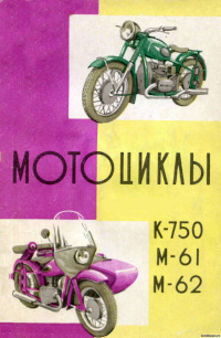
Описание устройства и руководство по эксплуатации, техническому обслуживанию и ремонту тяжелых мотоциклов моделей М-61, М-62 и К-750.
- Издательство: Физкультура и спорт
- Год издания: 1962
- Страниц: 211
- Формат: PDF
- Размер: 13,5 Mb
Описание устройства и руководство по эксплуатации и техническому обслуживанию мотоциклов модели М-72.
- Издательство: Военное издательство
- Год издания: 1948
- Страниц: 131
- Формат: PDF
- Размер: 16,6 Mb
Описание устройства и руководство по эксплуатации, техническому обслуживанию и ремонту мотоциклов модели М-72.
- Издательство: Машгиз
- Год издания: 1957
- Страниц: 237
- Формат: PDF
- Размер: 5,3 Mb
Руководство по эксплуатации и техническому обслуживанию мотоциклов модели М-72.
- Издательство: Машгиз
- Год издания: 1955
- Страниц: 81
- Формат: DjVu
- Размер: 6,6 Mb

Руководство по эксплуатации и техническому обслуживанию мотоциклов модели М-72.
- Издательство: Машгиз
- Год издания: 1964
- Страниц: 42
- Формат: PDF
- Размер: 1,1 Mb

Руководство по ремонту мотоциклов модели М-72.
- Издательство: Военное издательство
- Год издания: 1950
- Страниц: 390
- Формат: DjVu
- Размер: 13,3 Mb
Описание конструкции и руководство по эксплуатации мотоциклов модели М-72.
- Издательство: Военное издательство
- Год издания: 1956
- Страниц: 163
- Формат: PDF
- Размер: 16,6 Mb
Руководство по эксплуатации и техническому обслуживанию мотоциклов модели М-72-Н.
- Издательство: Машгиз
- Год издания: 1956
- Страниц: 21
- Формат: PDF
- Размер: 2,1 Mb
Руководство на английском языке по эксплуатации и техническому обслуживанию мотоциклов Урал 2002 года выпуска.
- Издательство: ИМЗ
- Год издания: —
- Страниц: 91
- Формат: PDF
- Размер: 2,1 Mb
Руководство по эксплуатации и техническому обслуживанию мотоциклов Урал М67-36.
- Издательство: ИМЗ
- Год издания: 1984
- Страниц: 113
- Формат: PDF
- Размер: 2,4 Mb
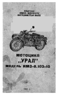
Руководство по эксплуатации и техническому обслуживанию мотоциклов Урал ИМЗ-8.103-10.
- Издательство: ИМЗ
- Год издания: 1990
- Страниц: 117
- Формат: PDF
- Размер: 73,7 Mb
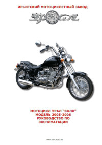
Руководство по эксплуатации и техническому обслуживанию мотоциклов Урал «Волк» 2005-2006 годов выпуска.
- Издательство: ИМЗ
- Год издания: —
- Страниц: 51
- Формат: PDF
- Размер: 4,9 Mb

Руководство по эксплуатации и техническому обслуживанию мотоциклов Урал моделей Турист, Спортсмен, Классик, Gear-Up и Ретро 2009 года выпуска.
- Издательство: ИМЗ
- Год издания: —
- Страниц: 52
- Формат: PDF
- Размер: 6,4 Mb

Руководство по ремонту тяжелых мотоциклов моделей К-750М, Урал и Днепр.
- Издательство: Машиностроение
- Год издания: 1986
- Страниц: 305
- Формат: PDF
- Размер: 29,4 Mb
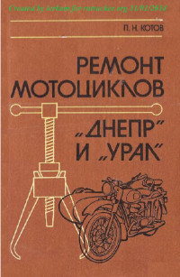
Руководство по ремонту тяжелых мотоциклов Урал и Днепр.
- Издательство: Россельхозиздат
- Год издания: 1987
- Страниц: 215
- Формат: PDF
- Размер: 27,0 Mb
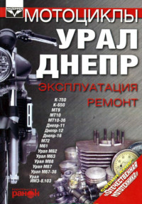
Руководство по эксплуатации и ремонту тяжелых мотоциклов Урал и Днепр.
- Издательство: Ранок
- Год издания: 2001
- Страниц: 237
- Формат: PDF
- Размер: 41,3 Mb

Руководство по эксплуатации, описание устройства и каталог запчастей мотоциклов Урал.
- Издательство: ИП Морозов
- Год издания: 2004
- Страниц: 81
- Формат: DjVu
- Размер: 3,1 Mb
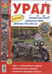
Руководство по эксплуатации, техническому обслуживанию и ремонту мотоциклов Урал.
- Издательство: Мир Автокниг
- Год издания: 2008
- Страниц: 275
- Формат: PDF
- Размер: 63,9 Mb
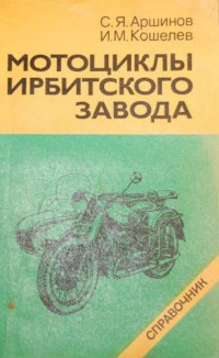
Руководство по эксплуатации, техническому обслуживанию и ремонту мотоциклов производства Ирбитского мотоциклетного завода.
- Издательство: Машиностроение
- Год издания: 1986
- Страниц: 119
- Формат: PDF
- Размер: 8,2 Mb

Руководства по эксплуатации
Руководство по эксплуатации М-72
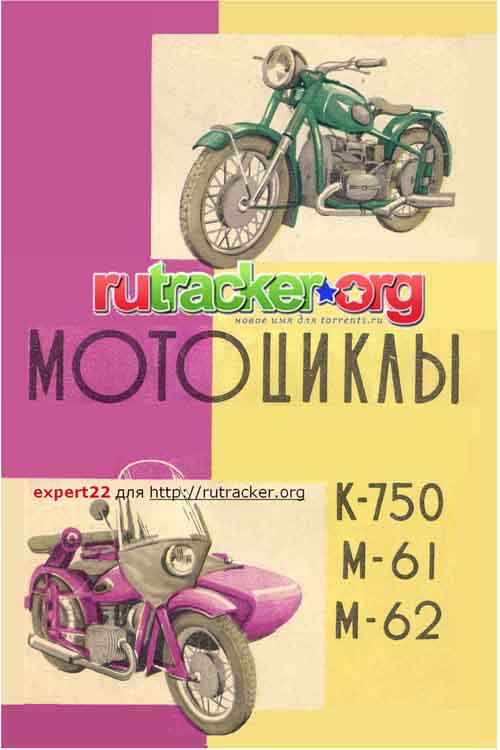
Руководство по эксплуатации М-61,М-62,К-750
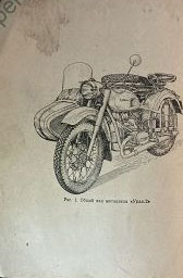
Руководство по эксплуатации М-63
Руководство по эксплуатации М-67-36
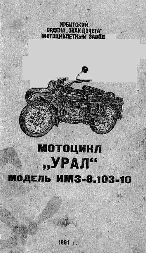
Руководство по эксплуатации ИМЗ-8.103-10
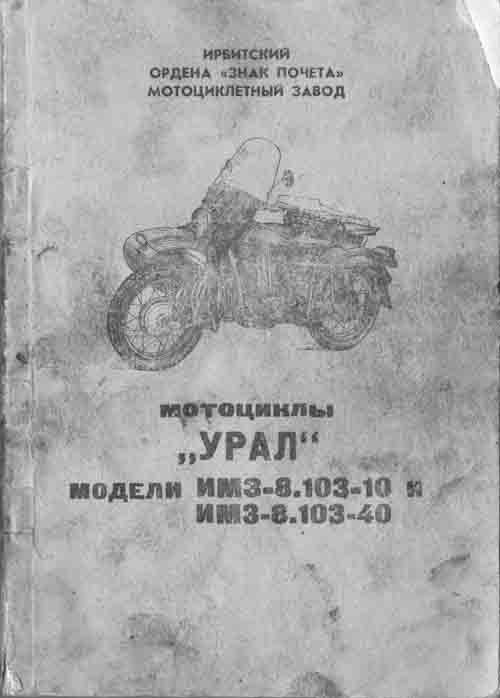
Руководство ИМЗ-8.103-10/ИМЗ-8.103-40
Книги по ремонту

Ремонт тяжелых мотоциклов П.Н.Котов, А.А.Капустин
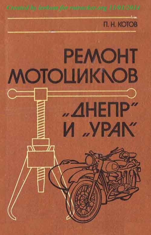
Ремонт мотоциклов «Урал», «Днепр» П.Н.Котов
Каталог мотоциклов
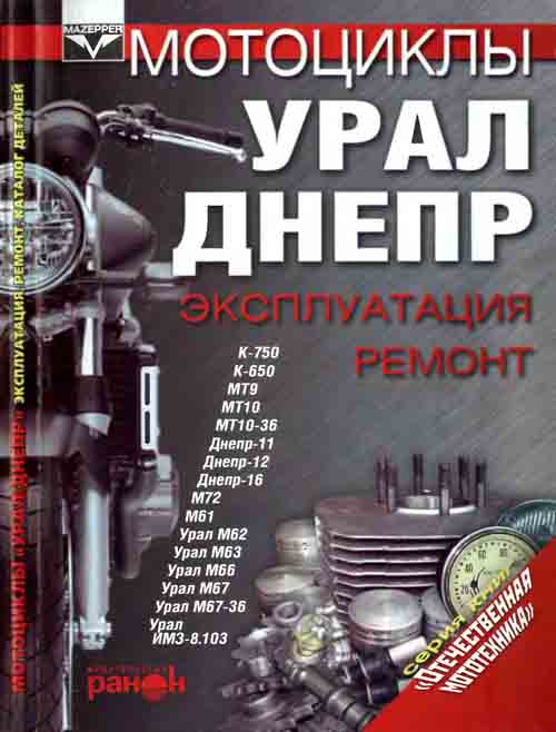
Мотоциклы «Урал», «Днепр» эксплуатация, ремонт
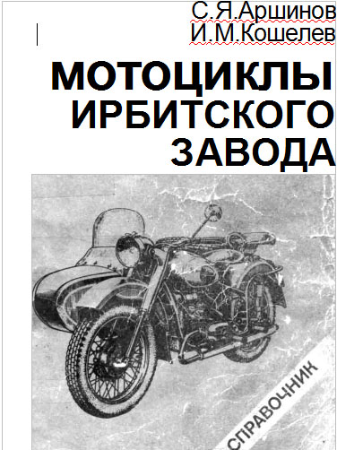
Мотоциклы Ирбитского завода, справочник
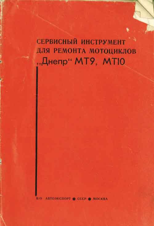
Инструмент для ремонта мотоциклов

4-я Красноармейская, 2А
Санкт-Петербург, 190005
Email: info@lenmoto.ru
Телефон: +7 (921) 930-81-18
Телефон: +7 (911) 928-08-06
Компания ЛенМото
Запчасти, аксессуары, экипировка, тюнинг для мотоциклов, скутеров, квадроциклов, снегоходов, багги, гидроциклов, катеров и лодочных моторов.
Подпишитесь на наши новости
Подписаться

- Manuals
- Brands
- URAL Motorcycles Manuals
- Motorcycle
- 750cc Series
- Repair manual
-
Contents
-
Table of Contents
-
Troubleshooting
-
Bookmarks
Quick Links
Repair Manual
750cc All Models
www.imz-ural.com
Related Manuals for URAL Motorcycles 750cc Series
Summary of Contents for URAL Motorcycles 750cc Series
-
Page 1
Repair Manual 750cc All Models www.imz-ural.com… -
Page 3: Table Of Contents
CONTENTS PAGE INTRODUCTION………………………..4 PREPARING THE MOTORCYCLE FOR REPAIR…………….5 DETERMINING THE TECHNICAL CONDITION OF THE MOTORCYCLE……..5 DISASSEMBLY AND REASSEMBLY………………..21 SERVICE AND REPAIR OF THE ENGINE……………….27 SERVICE AND REPAIR OF THE GEARBOX………………58 FINAL DRIVE AND DRIVE SHAFT REPAIR………………69 DISASSEMBLY AND REASSEMBLY OF THE FINAL DRIVE AND SIDECAR DRIVE….74 REPAIRING THE WHEELS……………………81 REPAIRING THE FRONT FORKS………………….85 INSPECTION AND REPAIR OF THE MOTORCYCLE FRAME…………86…
-
Page 4: Introduction
INTRODUCTION This Manual covers the service and repair of Ural motorcycles, model years 2001 thru 2006. Covered in this manual, replacement and/or repair of damaged parts, mechanical techniques, special tools, and testing procedures. This manual has been designed for use by qualified service technicians, mechanics, and engineers.
-
Page 5: Preparing The Motorcycle For Repair
PREPARING THE MOTORCYCLE FOR REPAIRS Irrespective of the type of anticipated repair work: — Wash the motorcycle; — Determine its technical condition. For this purpose inspect visually and try out the separate units and the motorcycle in running. Therefore, before estimating the technical condition of motorcycles that are brought for repairs in running condition, adjust: — Spark-plug gaps;…
-
Page 6
4. Determine the condition of the clutch mechanism as follows: — Check for separation of disks when the clutch is engaged; — Check for smooth engagement of the clutch; — See if there is slipping of the clutch; — See if there are noises when the clutch is engaged. 5. -
Page 7
13. Determine the condition of the controls by checking: — Condition of the handlebar with twist grips and levers, and their respective performance; — The throttle control twist grip for easy rotation; — Intactness of the cable sheath and the cables; — Working condition and proper functioning of the front, rear and side-car wheels;… -
Page 20
The local heating and overheating are determined by touch. Determine the condition of the clutch mechanism by checking its performance. With the engine at rest, engage the clutch, and then depress the kick-starter—the crankshaft should remain at rest. Start the engine, release the clutch and shift over to 1st gear— the motorcycle should remain motionless. -
Page 21: Disassembly And Reassembly
III. DISASSEMBLY AND REASSEMBLY If the technical condition of the motorcycle, as determined by checking, requires partial or complete dismantling of separate assembly units, sets or the motorcycle proper in order to repair or change parts, try and reduce to minimize the dismantling operations. Certain units can be partially dismantled without removing them off the motorcycle.
-
Page 22
2. REMOVING AND REINSTALLING THE GEARBOX To take off the gearbox without removing the engine from the motorcycle: — Remove the air cleaner, the storage battery; — Disconnect the adjusting bolt of the clutch control cable from the clutch engaging lever at the gearbox;… -
Page 23
Having tightened up all the fasteners, take the motorcycle off the stand and check the camber and toe-in of the wheels. By placing wooden bars along the motorcycle wheels and the sidecar wheel, check the toe- in of the wheels. The spacing between the bars in front (along the axis of the front wheel) should be 10-12 mm less than that at the rear (along the axis of the rear wheel). -
Page 24
When the motorcycle has the disc brake insert a plate about 4 mm thick to prevent the brake pads from getting out of the caliper. To reinstall the front wheel on the motorcycle, perform the above operations in reverse order. When reassembling the axle in place, lubricate it with motor oil. To remove the rear wheel proceed as follows: — Remove the cotter pin of the axle slotted nut, unscrew the nut, loosen the swinging fork left- hand arm clamp bolt nut and remove the axle together with the protective cap;… -
Page 25
9 REMOVING AND REINSTALLING THE FRONT FORK To remove the front fork: — Remove the front wheel (see subsection 6) — Undo the nut of the bolt fastening electronic ignition system or horn and take the bolt out — Undo the steering damper tightening bolt and remove all the steering damper washers — Remove the gas tank (see subsection 5) — By unscrewing the handlebar bracket nuts remove the handlebar;… -
Page 26
12. REMOVING AND REINSTALLING OF THE STARTER To remove the starter proceed as follows: — Disconnect wires from the battery terminals and the starter — Slacken clamps and remove the intake branch pipe. — Undo two bolts fastening the starter to the gearbox using hex wrench. — Loosen air box fastenings — Lift the air box and remove the starter. -
Page 27
REPAIR OF THE ENGINE 1. DISASSEMBLY AND REASSEMBLING Removing and Reinstalling the Cylinder Head (the engine may be left on the motorcycle) Required tools and fixtures: — Pans for draining oil from the cylinder head cover; — 0.05 mm feeler gauge; — Crank handle 345-316-3. -
Page 28
Before installing the cylinder head cover in place, lubricate the rockshafts through the central oil holes in the shaft. Removing and Reinstalling the Cylinder (the engine may be left on the motorcycle, with the cylinder head re moved) Required tools: — Crank handle 345-316-3 for cranking the crankshaft;… -
Page 29
346-697 Fig.1 Crank handle 345-316-3 to crank the engine crankshaft 346-692 Fig.2 Compression of piston rings to insert them into the cylinder. 345-439-3 Fig. 4 Device 346-066-3 to remove and mount piston rings Fig. 3 Pressing out the piston pin 346-320 Fig. -
Page 30
— Mount the piston rings on the piston using device 346-066-3; — Fit the pin on the mandrel 346-320, and from the other side insert the guiding tapered tip into the piston pin hole. Cover the piston pin with oil — Match the hole in the piston and the hole in the connecting rod small end and press the piston pin in place by hand (Fig. -
Page 31
Before reassembling the cover, if the gasket has been removed, clean the surfaces of the joint from varnish remnants and apply a new coat of varnish to the surface at the joint on engine crankcase and install a new gasket, matching all the holes. Reinstall the covers reversing the sequence of operations;… -
Page 32
450-182 450-212 Fig. 9 Fig. 8 Measuring the backlash in timing gears Measuring the runout of timing gears The backlash in timing gears should not be more than 0.5 mm. If otherwise, change the gear set. The face runout should not exceed 0.1 mm for driving gear and 0.05 for driven gear. To remove the camshaft: — Turn off the screws fastening the camshaft flange gaining access through the holes in the timing driven gear;… -
Page 33
Removing and Reinstalling the Clutch (With the engine taken out of the motorcycle frame and the gearbox removed) For reassembling the clutch tool 345-429-3 is used. To remove the clutch plates: — Insert a screwdriver into the slits of screws fastening the clutch pressure plate and with light blows of a hammer against the screwdriver butt end knock off the metal flashes from the screw slits: — Loosen screws fastening the thrust plate… -
Page 34
345-429-3 345-042-3 Fig. 13 Fig. 12 Removing the flywheel Removing the clutch plates To reinstall the flywheel: — Fit the flywheel on the tapered end of the crankshaft; make sure that the rubber seal is correctly fitted on the flywheel hub and that the key coincides with the keyway in the flywheel hub; — Fit a lock washer on;… -
Page 35
Removing and Reinstalling the Crankshaft (With the flywheel, the camshaft, the pistons and the oil pump removed) Required tools are: — Puller 346-693 for removing bearing from the crankshaft front and rear journals; — Remover 345-339-3 for removing the driving timing gear; — Tool 346-682-01 for removing the bearing rear housing;… -
Page 36
346-682-01Ý 346-720 Fig. 18 Fig. 17 Device to press out the crankshaft Removing the rear housing — By turning the crankshaft, position the keyway of the flywheel facing up. By lifting the crankshaft front and lowering its rear portion, remove crankshaft from the engine crankcase (Figs 19 and 20);… -
Page 37
Having removed the crankshaft, clean the oil catchers from accumulated grit, also the mating surfaces of the crankcase with the housings and covers, wash thoroughly and inspect all the parts, make necessary measurements. Should wear or other discrepancies from the technical requirements be revealed, replace the crankshaft. -
Page 38
-Having centered the rear bearing housing relative to the fastening holes with press and kit of tools 346-720 coat the rear sealing surface of the crankcase with varnish, apply gasket on the rear housing and press in the rear bearing housing into the crankcase (33-35) Fig.33 Fig.34 Fig.35… -
Page 39
2. REPAIRING ENGINE UNITS AND PARTS When repairing assembly units, remember to ensure positive or negative allowances between the mating sufaces, which should fall within the values set by the manufacture and are listed in Table 4. The maximum tolerated limits of wear and clearances between the principal mating parts of the engine, are given in Table 5. -
Page 46
Measure the radial play in the connecting rod big end with the help of indicator by resting the feeler pin on the big end in the centers (Fig. 35). The radial play should be within 0.10 mm. If otherwise, change the crankshaft. Measure the axial play between the crankshaft cheeks and the connecting rod big end using the feeler;… -
Page 47
Measure the turning of the crankpin in the centers using the indicator. Insert mandrel 457-034 into the connecting rod small ends. Choose the mandrel color to match that of the small end holes. Measurements should be taken in two positions of the crankshaft (Fig 38-39). The difference in measurements should not exceed 0.5 mm. -
Page 48
Replace the piston rings, if the following faults are diagnosed: Large sections of surfaces not properly embedded to the cylinder, cracks or peeling; lack of resilience of the piston rings proper. Measure the piston rings: — In five or six points by their height; — In the most worn-out points on the ring circumference (radial thickness). -
Page 49
Repairing the Valve Timing Mechanism The following troubles of the engine require repairs of the timing mechanism: — Loss of compression in the cylinder due to leaky valves, followed by a drop in engine power, increase in the gasoline consumption, and difficulties in starting the engine; — Increased performance noises of the timing mechanism;… -
Page 50
Fig. 40. Removing the valve springs Fig. 41. Measuring the side play between the valve and bush guide… -
Page 51
Substitute the bushing proceeding as follows: — Remove the deposits from the guide bushing (including the shaft); — Fasten the cylinder head in the vice, insert mandrel 345-047-3 and press off the valve guide bushing; — Check the condition of the hole in which the guide bushing is to be fitted, heat the head to 200 °C and having fitted the guide bushing on the mandrel 345-047-3, press the bushing in place, provide a clearance of 20 mm from the thrust plane of the spring bottom washer to the bushing edge;… -
Page 52
Fig. 42. Pressing the valve seat out Once a uniform dull-gray color (with no black spots) is obtained on the working surfaces of the valve and the seat, the grinding is considered satisfactory. After the grinding-in, wash the valves, the seats, the guide bushings, the neck and the cylinder head combustion chamber to remove all the traces of the grinding compound, then wipe dry. -
Page 53
Fig. 43. Left hand and right hand rocking arms assemblies Check the rockshaft and the rocking armhole for cracks, dents, scores, check wear of the rockshaft and the bores of the rocking arms. If the wear of shafts or bores in the rocking arms exceeds 0.07 mm, replace the defective parts. -
Page 54
Timing drive gears. The required tool is puller 345-659-3 for removing and forcing in the timing gear on the camshaft. Remember that abnormal noises of the timing drive gearing are usually due to wear of the teeth and, subsequently, an increased backlash or irregular lubrication of gears. Check the backlash when dismantling the engine or when replacing the gears. -
Page 55
Oil lines. In the course of total of partial dismantling of the engine, especially when reassembling, pay attention to correct mating of the oil ducts and clean them properly. Also see that the gaskets in the joint planes do not overlap the holes, the joints are tight with no leaks of oil. -
Page 56
3. ADJUSTMENT AND RUNNING-IN OF THE ENGINE AFTER REPAIRS After repairs and reassembly, adjust and run in the engine in order to check the quality, of repair work and assembly and ensure the embedding of its friction parts. A special test stand with forced air cooling should be employed for running-in. -
Page 57
Adjust the carburetors for in-step operation of engine cylinders as follows: — Start the engine and set a speed of 1,500 to 1,800 min; — By cutting off alternately each cylinder determine by ear whether both cylinders ensure the same speed. Adjust the engine speed to be the same to each cylinder. Turning in or off the cable sheath guides altering the throttle valves lift performs the adjustment of carburetors. -
Page 58
REPAIRING THE GEARBOX 1. DISMANTLING AND REASSEMBLING THE GEARBOX Removing and Reinstalling the Clutch Release Mechanism (with the gearbox removed from the motorcycle) To remove the clutch release mechanism (Fig. 44): — Remove the clutch release arm (Fig.44, Pos.1); — By pressing on the front end] of the clutch release rod (Fig.44, Pos.2), remove the clutch release slider, the thrust ball bearing, the rod tip and finally the clutch release rod. -
Page 59
Removing the Gear Shift Mechanism The gearshift mechanism consists of the following assembly units and parts: — Gear change foot pedal mechanism; — Switch quadrant with a shaft; — Reverse gear engagement mechanism with lever; — Gearshift forks; — Bracket with an intermediate gear. Tool required are the crank handle 346-403 for turning the clutch shaft and 346-710 to remove the flexible coupling plate. -
Page 60
Reassembly of the Gear Case Cover To reassemble the gear shift mechanism: — Place home the gear case cover with the split joint upwards (Fig.48); — Set the return spring of the gear shift mechanism by driving the spring ends behind the stop; — Set the quadrant shaft with its short end into the hole in the right hand cover. -
Page 61
— Fit the kick-starter shaft with gears into the cover bringing the gears in mesh (Fig. 52); — Set the bracket with intermediate gear; — Having the reverse gear quadrant pressed out insert the bracket shaft into the cover hole (Fig. -
Page 62
— Set and tighten up seven bolts fastening the gear case cover, the tightening torque being 6.4-7.8 Nm — Having turned the shaft for about 120 degrees anticlockwise by a wrench and sunk it in axial direction to 8 mm minimum cock spring of the kick-starter and free the shaft. The shaft should get out of the cover and lock (Fig.57). -
Page 63
After full disassembly of the gearbox or repair of the gearshift mechanism, adjust the latter by turning the clutch shaft with a special crank handle 346-403 (Fig. 63). Fig.64 Fig.63 To adjust proceed as follows (Fig. 63): — Undo four screws Mõ5 and remove the right hand cover of the gearbox, covering the shaft of the quadrant. -
Page 66
Table 10 Maximum Tolerated Limits of Clearances and Wear Between the Principal Mating Members of Gearbox, mm Tolerated limits Parts and mating members wear on diameter axial diameter clearance clearance Main shaft to main shaft gearing 0.25 Gear shift fork shaft to shift forks 0.25 Gear shift forks to gear engaging sleeve (width) 1.00… -
Page 67
Remove the return spring and ratchet crank from the shifting mechanism. — Moving the quadrant shaft to the left take out the shaft from the gearbox cover; — Remove the plate from the quadrant shaft and take the splint out of the quadrant. Wash the dismantled parts and inspect thoroughly, paying attention to accurate fitting of pin, pawl axle and the pawl. -
Page 68
Kick-starter shaft. Remove the kick-starter shaft, wash and inspect it thoroughly paying attention to condition of the pawl working edge and to condition of the gear ratchet teeth. If any defects are revealed, dismantle the kick-starter shaft, as follows: — Press out the shaft bushing pin by slightly knocking with a hammer against the end of protruding portion, remove the shaft bushing, then the gear;… -
Page 69
REPAIRING THE FINAL DRIVE AND THE DRIVESHAFT 1. DISMANTLING AND REASSEMBLING THE FINAL DRIVE AND THE DRIVE SHAFT (WITH THE FINAL DRIVE REMOVED FROM THE MOTORCYCLE) Removing and Reinstalling the Drive Shaft To disconnect the drive shaft from the final drive proceed as follows: — Uncotter the nut of the wedge bolt, unscrew the nut and using a soft mandrel knock the wedge bolt out;… -
Page 70
Having dismantled, wash, inspect and change the defective parts, if necessary. Reassemble the universal joint as follows: — Smear the inner surfaces of the needle bearings with grease Litol-24 and pack the needles into the bearings; — Fit the rubber sealing collars and holders, with the latter covering the collars, on the inserted pins of the universal joint cross;… -
Page 73
Repairing the Drive Shaft The drive shaft will call for repairs when any major troubles are revealed in the course of operation, i. e. shaft bent, universal joint worn-out, flexible coupling worn-out, etc. Inspect all the parts carefully, paying special attention to the mated friction surfaces and check the condition of: — Flexible joint coupling;… -
Page 74: Disassembly And Reassembly Of The Final Drive And Sidecar Drive
DISASSEMBLY AND REASSEMBLY OF THE FINAL DRIVE AND SIDECAR DRIVE (With the drive shaft dislodged) To dismantle the final drive (Fig. 67): — Turn off the drain plug, drain oil, fill kerosene instead and by rotating the drive in both directions wash the inner cavity, then drain kerosene;…
-
Page 76
Assembly of the final drive with the sidecar drive — Press in the external cage of the hub roller bearing into the final drive gear case using the mandrel (Fig. 68) — Using an appropriate tool press bearing 3086304 onto the driving bevel gear. — Using an appropriate tool press internal cage of the roller bearing onto the driving bevel gear;… -
Page 77
— Put the final drive cover onto the stand — Using a mandrel press the drive shift shaft collar (Fig. 73) — Using a mandrel press collar 55-80-8 into the final drive cover (Fig. 74…76) — Using a mandrel press bearing 7000111 into the final drive cover (Fig. 75…76) — Put the final drive cover onto a support Fig.75 Fig.76… -
Page 78
Fig. 81. Fig. 82. Fig. 80. Installing the stop Pressing the bearing in Installing the drive shift shaft — Degrease eight bolts fastening the hub of the final drive driven gear — Degrease eight threaded holes in the driven bevel gear — Set the hub onto the driven gear. -
Page 79
Fig. 86. Fig. 89 Fig. 88 Fig 87. Setting the adjustment Setting the final drive cover Setting the shims Setting the rollers ring and the distance ring — Put washers M8 onto studs, screw nuts in, set distance bushings onto the studs M10 and tighten the nuts to 14-18 Nm. -
Page 80
Dissembling the sidecar wheel drive shaft (The drive shaft disconnected from the final drive) To disassemble the drive shaft proceed as follows: — Remove the sidecar wheel — Remove the adjusting nut from the brake tie rod — Undo three bolts fastening the cover of the brake drum and remove the cover with brake shoes (Fig.93, Pos.1) — Put the mandrel onto the sidecar wheel axle and remove the sidecar wheel shaft slightly hammering the mandrel. -
Page 81: Repairing The Wheels
VIII. REPAIRING THE WHEELS Having removed the wheel and prior to repairs, check: — wear of tires and their possible damage; — cracks and dents of the wheel rim; — wear on the brake drum surface; — wear in the taper roller bearings and spacers; — radial and side run-out of the rim and tire;…
-
Page 82
— insert a portion of the tire bead into the rim well and use the tire irons to slip the hole bead inside, moving it towards the rim shoulder; — insert the inner tube valve into the hole in the rim, insert the slide valve into the tube valve, inflate the tube slightly and insert it into the tire casing, making sure that it is spread uniformly without any wrinkles;… -
Page 83
2. REPAIRING THE WHEEL ASSEMBLY UNITS AND PARTS Repairing the Tire (with the tire removed) Inspect the tire removed. If tire tread wear, tire side damage, deterioration of the cord or breakage of the bead wire are evident, change the tire. .If deterioration of cord is insignificant, send the tire to a specialized repair shop. -
Page 84
Repairing the Wheel Rim and Changing the Spokes The required tool is the wrench for driving in spoke nipples. If cracks or dents on the rim are evident, replace it. Proceed in the following order: — Using the wrench, turn all the nipples from the spokes, take the spokes out, and inspect them. Replace defective spokes and nipples;… -
Page 85: Repairing The Front Forks
IX . REPAIRING THE FRONT FORKS 1. DISMANTLING AND REASSEMBLING THE FRONT FORK It is possible to partially dismantle or repair the front fork without taking the entire assembly off the motorcycle. Removing and reinstalling the front fork leg (With the front wheel removed, the front fork remaining on the motorcycle) To dismantle the front fork leg: — Remove the front feneder when it is fastened to the fork leg tips;…
-
Page 86
Fig.102 Fig.103 Fig.105 REPAIRING THE MOTORCYCLE FRAME Check condition of the motorcycle frame, having first washed it to remove dirt, oil and dust. Repair the motorcycle frame, when external damage, cracks or other defects rendering further operation impossible are revealed. In case of serious breakage, cracks or damage, replace the frame or its separate parts. -
Page 87: Handle Bars And Control Cables
HANDLEBARS AND CONTROL CABLES 1. DISMANTLING AND REASSEMBLING THE THROTTLE COTROL TWIST-GRIP To dismantle the twist-grip: — Undo the screws and remove the carburetor covers together with the throttles; — Compress the throttle springs and remove the cable tips; — Undo the extreme screws fastening the halves of the switch body and remove the upper part; — Turn to yourself the throttle control twist-grip and remove the cable tips out of the slider;…
-
Page 88: Electrical Equipment
XIV. REPAIRING THE INTAKE AND THE EXHAUST SYSTEMS Repair the intake and the exhaust systems (the air cleaner, «the air corrector, intake branch pipes, exhaust pipes and silencers) whenever necessary; inspect them in the course of partial or total dismantling of the motorcycle and proceed with repairs when the troubles revealed render further operation of the motorcycle impossible.
-
Page 89
Table 13 # of the fuse (See Fig. 119) Circuit description 1 (16 A) Marking lights, high beam 2 (8A) Parking lights 3 (16 A) Horn, brake lights 4 (8 A) Ignition 5 (8 A) Blinker relay 2. STORAGE BATTERY The motorcycle is equipped with a dry storage battery with capacity of 18-32 A. -
Page 90
To ensure full charging of the battery: — Top up the cells with distilled water or acidic solution with .a density of 1.40 depending on the electrolyte density; — Charge with 1.5-2.0 A current until abundant degassing is evident in all the cells and specific gravity of electrolyte and voltage in all the cells are stable for the period of 2 h. -
Page 91
Fig.105 Fig.106 Disassembly and Assembly of the alternator drive To disassemble the alternator: — Fix the alternator gear with the drive — Remove the cotter pin from the alternator nut and undo it. — Press off the alternator gear from the shaft using and appropriate tool — Remove the key from the alternator shaft — Undo four nuts fastening the alternator to the drive and separate them — Remove the packing ring form the casing… -
Page 92
Fig. 110. Fig. 111. Fig. 109. Installing the flange Installing the seal Pressing the bearings in — Using the mandrel press the drive shaft in until it stops (Fig. 112) — Press the key in the drive shaft (Fig. 113) — Having matched the key recess and alternator gear heated to 200 deg. -
Page 93
4. STARTER To start the engine up a little electric motor is required, i.e. starter. The starter must provide about 300 rpm to start the engine. It is possible only when the starter operates perfectly and the battery is sufficiently charged. The starter consists of a drive housing, poles and a collector. -
Page 94
Faults, diagnostics and remedy Fault Remedy When switched on the starter does not rotate, the starting relay does not operate 1. The battery wrong or totally exhausted 1. Charge or replace the battery 2. The battery terminals are badly corrupted, wire ends 2. -
Page 95
5. IGNITION SYSTEM DEVICES The ignition system comprises the following devices: — Microprocessor unit — Double-terminal ignition coil — Spark plugs — Interference suppression resistor Double-terminal ignition coil Type…………………………………………………KMSZ 3705060 Rated voltage on terminals of primary winding ……………….12 V Gap between discharges and high voltage terminals, mm………5.5 Camshaft maximum speed of uninterrupted sparking, rpm …..100 Spark plug Type ……………………………..NGK BP7H… -
Page 96
Fig. 118. Ignition timing Table 16 List of Lighting and Light-Signal Equipment Equipment Type Purpose of lamp Type of lamp Lamp power, W bulb Headlamp ÔÃ137Â High-low beam H4 12V60/55W 60/55 Parking light A12-4 Speedometer ÑÏ158 Lighting of speedometer A12-1 Pilot lamp 2202.3803-07 Direction indicator pilot… -
Page 97
6. HORN Type…………………………………………………………..trumpetless, 20.3721000-01 Sound pressure at the distance of 20 meters at 12V, dB…….. 105-125 Voltage, V……………………………………………………..11-15 Current drain at 12 V. A ………………………………..…….less than 3 Frequency at 12 V, Hz ………………………………….……..350-450 Mostly the failure of the horn is caused by dirt on the horn diaphragm or by defective push button. -
Page 99
Seals and rings used with URAL motorcycle Dimensions D-d-H Used before 2005 Used since 2005 Cam shaft seal, 30.1-15-7 (621124-01) RUBENA 30-16-8 (IMZ-8.103-01083) Crankshaft seal, VITON 80-55-10 RUBENA 80-55-10 (IMZ-8.108-01081) (IMZ-8.108-01081) Seal of right hand cover of gearbox case RUBENA 25-12-7(IMZ-8.103-04017) 25.1-12.3-7 (62-04017) Clutch shaft seal 45-32-8 (62-04010) RUBENA 45-32-8 (IMZ-8.103-04010)
Мотоцикл Урал — История, описание, ремонт
Мотоциклы Урал – гордость отечественного мотопрома, изобретение, которое сразу же оценили за рубежом. По сей день компания экспортирует основную часть своей продукции, лишь 3-5 % мототехники реализуется в пределах Российской Федерации. За границу мотоциклы Урал уходят: в страны Европы, в Китай, Австралию, Японию, США, Канаду, африканские страны. Такой высокий спрос обуславливается отличным качеством, которое производители сохраняют на протяжении десятков лет, начиная с выпуска армейских моделей.
Немного из истории
Не секрет, что прототипом первых мотоциклов Урал стала модель R-71 концерна BMW. Версий о том, как чертежи и разработки попали к нашим инженерам, две. Первая объясняет это тем, что к нам через посредников попали несколько мотоциклов в собранном виде. В СССР их разобрали, тщательно изучили и скопировали конструкцию всех деталей и узлов. По второй версии, которую подтверждают многие официальные лица, в те годы у Германии и Советского Союза были дружественные отношения. Вся документация, чертежи и лицензия были переданы немцами на добровольной основе.

Это как раз был момент запуска производства, велись обсуждения, и рассматривалось несколько вариантов в качестве прототипа. К примеру, не исключалось изготовление мотоцикла Урал на базе английской или американской машины. Но немецкая модель оказалась более удачной и подходящей по многим параметрам. Особенность в том, что изначально наши мотоциклы Урал практически не отличались от немецкой модели. Позже в конструкцию были внесены корректировки: бензобак стал больше (с 14 литров увеличился до 22), спицы на колёсах сделали более толстыми.
Руководства эксплуатации и ремонт
Руководство по эксплуатации и ремонту мотоцикла Урал: скачать ![]()
Руководство по ремонту Урал: скачать ![]()
Руководство по эксплуатации и ремонту мотоцикла Урал Волк: скачать ![]()
Хронология трансформаций производства
- 1941 год – в Москве выпущен первый опытный образец для военных целей. Мотоцикл был представлен на одобрение Верховному Главнокомандующему, Сталин дал согласие на массовое изготовление.
- 1942 год – выпуск первой партии мототехники в городе Ирбит на Урале. Тремя месяцами ранее, в конце 41-го произошла эвакуация заводских мощностей из Москвы.
- 1955 год – сошли с конвейера первые гражданские машины, которые стали и в буквальном, и в переносном смысле «рабочими лошадками». Они, действительно, были надёжные и долговечные, причём нередкой была такая картина: мотоцикл был нагружен мешками с овощами или перевозил целую копну сена.
- 1961 год – ирбитская техника получила своё официальное название – «Урал». Этот период стал стартом для широкосерийного производства. Каждый гражданин СССР мечтал приобрести новый Урал, а стоил он примерно 10 зарплат.
- 1993 год – выпуск трёхмиллионной машины Урал.
В наше время – Урал стал легендой отечественного мотопрома. Сейчас – это мелкосерийное производство с импортными комплектующими. Численность каждой серии – не более 20-30 экземпляров.

Особенности и преимущества модельного ряда Урал
Среди преимуществ пользователи оценили высокую проходимость, возможность эксплуатации в условиях бездорожья, простоту в ремонте. Машина не прихотлива к качеству горючего, масел и прочих смазочных материалов. Мотоциклы Урал – надёжная, мощная техника, она спокойно развивает скорость свыше 90 км/час. В целом, это мелкосерийное производство мототехники высокого качества. Эксклюзивная продукция, да и только!
Запчасти для Урал

