-
Contents
-
Table of Contents
-
Troubleshooting
-
Bookmarks
Quick Links
®
Powerware
9125
User’s Guide
2500–3000 VA
www.powerware.com
Related Manuals for Powerware 9125
Summary of Contents for Powerware 9125
-
Page 1
® Powerware 9125 User’s Guide 2500–3000 VA www.powerware.com… -
Page 2
Powerware is a registered trademark and Fourth-Generation Online, Advanced Battery Management Plus (ABM Plus), X-Slot, and ConnectUPS are trademarks of Powerware Corporation. Copyright 2002 Powerware Corporation, Raleigh, NC, USA. All rights reserved. No part of this document may be reproduced in any way without the express written approval of Powerware Corporation. -
Page 3
Class A EMC Statements FCC Part 15 NOTE This equipment has been tested and found to comply with the limits for a Class A digital device, pursuant to part 15 of the FCC Rules. These limits are designed to provide reasonable protection against harmful interference when the equipment is operated in a commercial environment. -
Page 4
Special Symbols The following are examples of symbols used on the UPS to alert you to important information: RISK OF ELECTRIC SHOCK — Indicates that a risk of electric shock is present and the associated warning should be observed. CAUTION: REFER TO OPERATOR’S MANUAL — Refer to your operator’s manual for additional information, such as important operating and maintenance instructions. -
Page 5: Table Of Contents
ABLE OF ONTENTS 1 Powerware 9125 – The Ultimate Online UPS! ……2 Safety Warnings .
-
Page 6
…………Powerware 9125 User’s Guide (2500–3000 VA) Rev B www.powerware.com… -
Page 7: Powerware 9125 — The Ultimate Online Ups
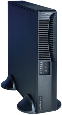
— causing hours of lost productivity and expensive repairs. With the Powerware 9125, you can safely eliminate the effects of power disturbances and guard the integrity of your equipment. Figure 1 shows the Powerware 9125 UPS with an optional Extended Battery Module (EBM).
-
Page 8
: Flash memory provides easy upgrades or reconfiguration capability without requiring a service call. : The Powerware 9125 is backed by worldwide agency approvals. Powerware 9125 User’s Guide (2500–3000 VA) Rev B www.powerware.com… -
Page 9: Safety Warnings
For UPS models with hardwired outputs, overcurrent protection for the output AC circuit(s) is to be provided by others. For UPS models with hardwired outputs, suitably rated disconnect switches for the output AC circuit(s) are to be provided by others. Powerware 9125 User’s Guide (2500–3000 VA) Rev B www.powerware.com ®…
-
Page 10
I overensstemmelse med internationale normer og bestemmelser for el-installation må det udstyr, der er forbundet til udgangen af denne UPS, tilsammen ikke overskride en jordafdelingsspænding på mere end 1,5 milliampere. Powerware 9125 User’s Guide (2500–3000 VA) Rev B www.powerware.com ®… -
Page 11
Verwijder de ingangsnoer niet of haal de stekker van de ingangsnoer er niet uit terwijl de UPS aan staat. Hierdoor zou de UPS en uw aangesloten apparatuur geen aardebeveiliging meer hebben. Powerware 9125 User’s Guide (2500–3000 VA) Rev B www.powerware.com ®… -
Page 12
Volg de desbetreffende aanwijzingen op. De batterijen moeten op de juiste wijze worden opgeruimd. Raadpleeg hiervoor uw plaatselijke voorschriften. Nooit batterijen in het vuur gooien. De batterijen kunnen ontploffen. Powerware 9125 User’s Guide (2500–3000 VA) Rev B www.powerware.com ®… -
Page 13
Akusto saattaa aiheuttaa sähköiskun tai syttyä tuleen, jos akusto kytketään oikosulkuun. Noudata asianmukaisia ohjeita. Akusto täytyy hävittää säädösten mukaisella tavalla. Noudata paikallisia määräyksiä. Älä koskaan heitä akkuja tuleen. Ne voivat räjähtää. Powerware 9125 User’s Guide (2500–3000 VA) Rev B www.powerware.com ®… -
Page 14
Pour les models UPS ayant des sorties câblées, les interrupteurs de déconnexion convenables pour le(s) circuit(s) de sortie de courant alternatif doivent être fournie par un autre fournisseur. Powerware 9125 User’s Guide (2500–3000 VA) Rev B www.powerware.com ®… -
Page 15
Luftfeuchtigkeit (max. 95 %) betreiben. Um internationale Normen und Verdrahtungsvorschriften zu erfüllen, dürfen die an den Ausgang dieser USV angeschlossenen Geräte zusammen einen Erdschlußstrom von insgesamt 1,5 Milliampere nicht überschreiten. Powerware 9125 User’s Guide (2500–3000 VA) Rev B www.powerware.com ®… -
Page 16
Ìçí âãÜæåôå áðü ôçí ðñßæá ôï êáëþäéï ôñïöïäïóßáò üôáí ôï UPS åßíáé áíïé÷ôü. Ì áõôü ôïí ôñüðï áöáéñåßôå ôç ãåßùóç áóöáëåßáò áðü ôï UPS êáé áðü ôïí åîïðëéóìü ðïõ åßíáé óõíäåäåìÝíïò ìå ôï UPS. Powerware 9125 User’s Guide (2500–3000 VA) Rev B www.powerware.com ®… -
Page 17
áðü õøçëü ñåýìá âñá÷õêõêëþìáôïò. ËáìâÜíåôå ôéò êáôÜëëçëåò ðñïöõëÜîåéò. Áðáéôåßôáé óùóôÞ äéÜèåóç ôùí óõóóùñåõôþí. Äåßôå ôïõò ôïðéêïýò êáíïíéóìïýò ðïõ áöïñïýí ôéò áðáéôÞóåéò äéÜèåóÞò ôïõò. ÐïôÝ ìçí ðåôÜôå ôïõò óõóóùñåõôÝò óôç öùôéÜ, ãéáôß ìðïñåß íá åêñáãïýí. Powerware 9125 User’s Guide (2500–3000 VA) Rev B www.powerware.com ®… -
Page 18
Nei sistemi UPS provvisti di uscite cablate, i sezionatori di corrente nominale adeguata per il/i circuito/i a corrente alternata in uscita devono essere forniti da terzi. Powerware 9125 User’s Guide (2500–3000 VA) Rev B www.powerware.com ®… -
Page 19
For UPS systemer med fastkoplete uttak, må overstrømvern for vekselstrømuttak(ene) stilles til rådighet av andre. For UPS systemer med fastkoplete uttak, må passende utkoplingsbrytere for vekselstrømuttak(ene) stilles til rådighet av andre. Powerware 9125 User’s Guide (2500–3000 VA) Rev B www.powerware.com ®… -
Page 20
Para estar de acordo com os padrões internacionais e os regulamentos de fiação, o equipamento total conectado à saída desta UPS não deve ter uma corrente de fuga à terra maior que 1,5 miliampères. Powerware 9125 User’s Guide (2500–3000 VA) Rev B www.powerware.com ®… -
Page 21
даже когда ИБП не подключен к сети переменного тока. Не отсоединяйте сетевой шнур и не извлекайте его вилку из розетки при включенном ИБП. При этом защитное заземление отключается от ИБП и от оборудования, подключенного к ИПБ. Powerware 9125 User’s Guide (2500–3000 VA) Rev B www.powerware.com ®… -
Page 22
соответствующие меры предосторожности. Необходимо соблюдать правила утилизации аккумуляторов. Обратитесь к местным нормативным актам за информацией о требованиях к утилизации. Никогда не бросайте аккумуляторы в огонь. Аккумуляторы могут взорваться под воздействием огня. Powerware 9125 User’s Guide (2500–3000 VA) Rev B www.powerware.com ®… -
Page 23
CA de salida será suministrada por terceros. Para los sistemas UPS con salidas cableadas permanentemente, los interruptores de desconexión debidamente clasificados para el/los circuito(s) de CA de salida serán suministrados por terceros. Powerware 9125 User’s Guide (2500–3000 VA) Rev B www.powerware.com ®… -
Page 24
Använd inte utrustningen nära vatten eller vid hög luftfuktighet (max 95 %). För att överensstämma med internationell standard och installationsföreskrifter får inte den totala utrustning som anslutits till uttagen på denna UPS-enhet ha läcksström som överstiger 1,5 milliampere. Powerware 9125 User’s Guide (2500–3000 VA) Rev B www.powerware.com ®… -
Page 25
Batterierna kan ge elektriska stötar eller brännskador från hög kortslutningsström. Följ tillämpliga anvisningar. Batterierna måste avyttras enligt anvisningarna i lokal lagstiftning. Använda batterier får aldrig brännas upp. De kan explodera. Powerware 9125 User’s Guide (2500–3000 VA) Rev B www.powerware.com ®… -
Page 26
Safety Warnings Powerware 9125 User’s Guide (2500–3000 VA) Rev B www.powerware.com ®… -
Page 27: Installation
UPS. Contact your service representative. UPS Setup The Powerware 9125 UPS is designed for flexible configurations and can be installed in a rack or as a standalone cabinet. If you are installing the UPS in a rack, continue to the following section “Rack-Mount Setup;”…
-
Page 28: Rack-Mount Setup
UPS and secure with the supplied screws (see Figure 2). 4. If installing optional EBMs, repeat Steps 1 through 3 for each cabinet. Mounting Bracket Mounting Handle Figure 2. Installing the Mounting Brackets Powerware 9125 User’s Guide (2500–3000 VA) Rev B www.powerware.com ®…
-
Page 29: Tower Setup
3. Position the pedestals over the end of the UPS cabinet so that the weight of the unit is evenly distributed. Secure the pedestals with the screws provided in the accessory kit. Powerware 9125 User’s Guide (2500–3000 VA) Rev B www.powerware.com ®…
-
Page 30
Figure 5. Pedestals with One Cabinet 5. Place the UPS cabinet horizontally so that the left end of the unit is accessible (see Figure 6). Figure 6. Installing UPS Pedestals with Two Cabinets Powerware 9125 User’s Guide (2500–3000 VA) Rev B www.powerware.com ®… -
Page 31
8. Carefully position the cabinets upright with the air vents at the top (see Figure 8 or Figure 9). Air Vents Figure 8. Pedestals with Two Cabinets Powerware 9125 User’s Guide (2500–3000 VA) Rev B www.powerware.com ®… -
Page 32
EBM Bracket Figure 10. Installing the EBM Brackets (Top View with Pedestals) 10. If installing additional EBMs, repeat Step 9 for each cabinet and continue to the following section, “EBM Installation.” Powerware 9125 User’s Guide (2500–3000 VA) Rev B www.powerware.com ®… -
Page 33: Ebm Installation
4. Continue to “Plug-Receptacle UPS Installation” on page 30 or “Hardwired UPS Installation” on page 32. UPS Battery Connector EBM Cable EBM Battery Connectors Figure 11. Typical EBM Installation (120V UPS Model Shown) Powerware 9125 User’s Guide (2500–3000 VA) Rev B www.powerware.com ®…
-
Page 34
NOTE Keep the EBM cable cover for future use. If the EBM is stored or removed from the UPS, the EBM cable cover must be installed as a safety precaution. Powerware 9125 User’s Guide (2500–3000 VA) Rev B www.powerware.com ®… -
Page 35
Repeat for each additional EBM. Up to four EBMs may be connected to the UPS. 10. Continue to the following section, “Plug-Receptacle UPS Installation” or “Hardwired UPS Installation” on page 32. Powerware 9125 User’s Guide (2500–3000 VA) Rev B www.powerware.com ®… -
Page 36: Plug-Receptacle Ups Installation
3. If an emergency power-off (disconnect) switch is required by local codes, see “Remote Emergency Power-Off” on page 36 to install the REPO switch before powering on the UPS. Powerware 9125 User’s Guide (2500–3000 VA) Rev B www.powerware.com ®…
-
Page 37
The UPS is now in Normal mode and supplying power to your equipment. NOTE The batteries charge to 90% capacity in approximately 3 hours. However, it is recommended that the batteries charge for 24 hours after installation or long-term storage. Powerware 9125 User’s Guide (2500–3000 VA) Rev B www.powerware.com ®… -
Page 38: Hardwired Ups Installation
For UPS models with hardwired outputs, suitably rated disconnect switches for the output AC circuit(s) are to be provided by others. The Powerware 9125 requires a dedicated branch circuit that meets the following requirements: : 16A, 2-pole circuit breaker for EH models/20A, 2-pole circuit breaker…
-
Page 39
5. Insert each conduit through a wiring access entry and attach the conduit fitting to the panel. Strip 0.52 (1.5 cm) of insulation from the end of each incoming wire. Powerware 9125 User’s Guide (2500–3000 VA) Rev B www.powerware.com ®… -
Page 40
8. Replace the terminal block cover. 9. If an emergency power-off (disconnect) switch is required by local codes, see “Remote Emergency Power-Off” on page 36 to install the REPO switch before powering on the UPS. Powerware 9125 User’s Guide (2500–3000 VA) Rev B www.powerware.com ®… -
Page 41
The UPS is now in Normal mode and supplying power to your equipment. NOTE The batteries charge to 90% capacity in approximately 3 hours. However, it is recommended that the batteries charge for 24 hours after installation or long-term storage. Powerware 9125 User’s Guide (2500–3000 VA) Rev B www.powerware.com ®… -
Page 42: Remote Emergency Power-Off
Installation Remote Emergency Power-Off The Powerware 9125 includes a REPO port that allows power to be switched off at the UPS output receptacles from a customer-supplied switch in a remote location. The REPO feature shuts down the protected equipment immediately and does not follow the orderly shutdown procedure initiated by any power management software.
-
Page 43
UPS by pressing the On button. 7. Activate the external REPO switch to test the REPO function. 8. De-activate the external REPO switch and restart the UPS. Powerware 9125 User’s Guide (2500–3000 VA) Rev B www.powerware.com ®… -
Page 44: Ups Rear Panels
Installation UPS Rear Panels This section shows the rear panels of the Powerware 9125 models. REPO Port Battery Connector Communication Port Fuse Holder Network X-Slot Transient Protector Two 5-20 Receptacles Circuit Protector Two 5-15 Receptacles 5-30 Receptacle Power Cord with 5-30P Figure 22.
-
Page 45
Figure 25. 2500/3000 VA, 208–240V Hardwired Rear Panel REPO Port Terminal Block Communication Port Network X-Slot Transient Protector Battery Connector with Cover Figure 26. 2500/3000 VA, 230V Hardwired Rear Panel Powerware 9125 User’s Guide (2500–3000 VA) Rev B www.powerware.com ®… -
Page 46
Installation Powerware 9125 User’s Guide (2500–3000 VA) Rev B www.powerware.com ®… -
Page 47: Operation
If you do not unplug or remove utility power from the UPS, it remains in Standby mode. Pressing the Off button while the UPS is in Battery mode causes the UPS to shut down immediately. Powerware 9125 User’s Guide (2500–3000 VA) Rev B www.powerware.com ®…
-
Page 48: Initiating The Self-Test
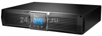
If the UPS finds a problem, an LED indicates where the problem is. For more information, see “Troubleshooting” on page 67. Operating Modes Powerware 9125’s front panel indicates the UPS status through the UPS indicators. Figure 27 shows the UPS front panel indicators and controls. Normal Mode Indicator…
-
Page 49: Normal Mode
10%. Each LED represents 1/4 of a full load rating. When all of the bar graph indicators are illuminated and the indicator flashes, power requirements exceed UPS capacity; see page 69 for more information. Powerware 9125 User’s Guide (2500–3000 VA) Rev B www.powerware.com ®…
-
Page 50: Battery Mode
Once these warnings are indicated, immediately complete and save your work to prevent data loss and similar difficulties. When utility power is restored after the UPS shuts down, the UPS automatically restarts. Powerware 9125 User’s Guide (2500–3000 VA) Rev B www.powerware.com ®…
-
Page 51: Bypass Mode
If the UPS is on battery for approximately five minutes and supporting a small electrical load (ˆ 10%), the UPS shuts down the load. This feature conserves battery power. To enable this feature, contact your service representative. Powerware 9125 User’s Guide (2500–3000 VA) Rev B www.powerware.com ®…
-
Page 52
Operation Powerware 9125 User’s Guide (2500–3000 VA) Rev B www.powerware.com ®… -
Page 53: Configuration
If you press the On button and nothing happens, the UPS is still in Operation mode. Repeat Step 1 for one beep ONLY to enter Configuration mode, and then perform Step 2. Powerware 9125 User’s Guide (2500–3000 VA) Rev B www.powerware.com ®…
-
Page 54
Configuration and Operation mode. Test/Alarm On Button Reset Button Press the On button to scroll to the next option. Figure 30. Using the Configuration Mode Powerware 9125 User’s Guide (2500–3000 VA) Rev B www.powerware.com ®… -
Page 55
220V for EU and EUH models and 208V for E and EH models are also available. Contact the help desk at one of the telephone numbers on page 70 for assistance. Powerware 9125 User’s Guide (2500–3000 VA) Rev B www.powerware.com ®… -
Page 56
Configuration Powerware 9125 User’s Guide (2500–3000 VA) Rev B www.powerware.com ®… -
Page 57: Additional Ups Features
: Load segments X-Slot Cards X-Slot cards allow the UPS to communicate in a variety of networking environments and with different types of devices. The Powerware 9125 is factory-installed with a Single-Port card and is compatible with any X-Slot card, including: : Multi-Server Card — has six serial communication ports that can communicate with UPSs, terminals, computers, and modems.
-
Page 58: Single-Port Card
To external device (tied to Pin 4) PnP from external device (default) or In / Out On Bypass relay contact (jumper-selectable) AC Fail AC Fail relay contact Power Source +V (8 to 24 volts DC power) Powerware 9125 User’s Guide (2500–3000 VA) Rev B www.powerware.com ®…
-
Page 59
2. Move the J3 jumper to the AS/400 position to enable the On-Bypass relay as shown in Figure 34. On-Bypass On-Bypass Disabled Enabled NORM AS/400 On-Bypass Relay Jumper (J3) Figure 34. On-Bypass Relay Jumper Powerware 9125 User’s Guide (2500–3000 VA) Rev B www.powerware.com ®… -
Page 60: Network Transient Protector
1. Connect the input connector of the equipment you are protecting to the jack labeled IN. 2. Connect the network or telephone cable (low voltage units only) to the jack labeled OUT. Figure 35. Network Transient Protector Powerware 9125 User’s Guide (2500–3000 VA) Rev B www.powerware.com ®…
-
Page 61: Load Segments
Figure 37. Load Segment 1 Load Segment 2 Figure 36. UPS Load Segments for 120V Models Load Segment 1 Load Segment 2 Figure 37. UPS Load Segments for 208V/230V Models Powerware 9125 User’s Guide (2500–3000 VA) Rev B www.powerware.com ®…
-
Page 62
Additional UPS Features Powerware 9125 User’s Guide (2500–3000 VA) Rev B www.powerware.com ®… -
Page 63: Ups Maintenance
After the five-second test is complete, the indicator should turn off (it may take a few seconds to turn off). If the indicator stays on, contact your service representative to order new batteries. Powerware 9125 User’s Guide (2500–3000 VA) Rev B www.powerware.com ®…
-
Page 64: Replacing Batteries
5. Replace the EBM. See “Recycling the Used Battery” on page 62 for proper disposal. 6. Reinstall the pedestals if removed in Step 3. 7. Reinstall the EBM brackets if removed in Step 2. Powerware 9125 User’s Guide (2500–3000 VA) Rev B www.powerware.com ®…
-
Page 65
EBM cable into the battery connector on the first EBM. Attach the fixed cover plate to the EBM cable. Brackets EBM Battery Connectors UPS Battery Connector EBM Cables Figure 38. EBM Connections (120V Model Shown) Powerware 9125 User’s Guide (2500–3000 VA) Rev B www.powerware.com ®… -
Page 66: How To Replace Internal Batteries
NOTE DO NOT attempt to open the left side. 2. Push down and unsnap the LED panel. 3. Disconnect the battery cable from the UPS and cut the battery cable wire tie. Battery Cable LED Panel Powerware 9125 User’s Guide (2500–3000 VA) Rev B www.powerware.com ®…
-
Page 67: Testing New Batteries
(it may take a few seconds to turn off). If the indicator stays on, check the battery connections. Call your service representative if the problem persists. Powerware 9125 User’s Guide (2500–3000 VA) Rev B www.powerware.com ®…
-
Page 68: Recycling The Used Battery
Do not discard the UPS or the UPS batteries in the trash. This product contains sealed, lead-acid batteries and must be disposed of properly. For more information, contact your local recycling or hazardous waste center. Powerware 9125 User’s Guide (2500–3000 VA) Rev B www.powerware.com ®…
-
Page 69: Specifications
C H A P T E R 8 PECIFICATIONS This section provides the following specifications for the Powerware 9125 models: : Electrical input and output : Environmental and safety : Weights and dimensions : Battery Table 4. Model Specifications Power Levels…
-
Page 70
UL 1778, UL 497A; IEC 60950; EN 50091-1-1; NOM-019-SCFI CSA C22.2, No. 107.1, 107.2; NOM-019-SCFI Agency Markings UL, cUL, NOM-NYCE CE, TUV-GS EMC (Class A) FCC Part 15, ICES-003 EN 50091-2, IEC 62040-2 Powerware 9125 User’s Guide (2500–3000 VA) Rev B www.powerware.com ®… -
Page 71
Batteries 2500 VA/1750W 7/16 28/57 48/90 68/150 88/200 3000 VA/2100W 5/13 25/55 38/72 54/120 70/160 NOTE Battery times are approximate and vary depending on the load configuration and battery charge. Powerware 9125 User’s Guide (2500–3000 VA) Rev B www.powerware.com ®… -
Page 72
Specifications Powerware 9125 User’s Guide (2500–3000 VA) Rev B www.powerware.com ®… -
Page 73: Troubleshooting
Figure 39. Alarm Indicators Silencing an Audible Alarm To silence the alarm for an existing fault, press the button. If UPS status changes, the alarm beeps, overriding the previous alarm silencing. Powerware 9125 User’s Guide (2500–3000 VA) Rev B www.powerware.com ®…
-
Page 74
Three minutes or less of battery power remains (depending on load configuration and battery charge). Prepare for a shutdown. Save your work and turn off your Warning — Low Battery equipment. Powerware 9125 User’s Guide (2500–3000 VA) Rev B www.powerware.com ®… -
Page 75
5 seconds until all LEDs are off and restart the UPS. defective. If the overload condition persists (101–110% for 2 minutes Overload or 111–150% for 30 seconds), the UPS automatically shuts Continuous audible alarm down. Powerware 9125 User’s Guide (2500–3000 VA) Rev B www.powerware.com ®… -
Page 76: Service And Support
A replacement or repair unit will be shipped, freight prepaid for all warrantied units. NOTE For critical applications, immediate replacement may be available. Call the for the dealer or distributor nearest you. Help Desk Powerware 9125 User’s Guide (2500–3000 VA) Rev B www.powerware.com ®…
-
Contents
-
Table of Contents
-
Troubleshooting
-
Bookmarks
Quick Links
®
Powerware
9125
User’s Guide
2500–3000 VA
www.powerware.com
Related Manuals for Powerware 9125
Summary of Contents for Powerware 9125
-
Page 1
® Powerware 9125 User’s Guide 2500–3000 VA www.powerware.com… -
Page 2
Powerware is a registered trademark and Fourth-Generation Online, Advanced Battery Management Plus (ABM Plus), X-Slot, and ConnectUPS are trademarks of Powerware Corporation. Copyright 2002 Powerware Corporation, Raleigh, NC, USA. All rights reserved. No part of this document may be reproduced in any way without the express written approval of Powerware Corporation. -
Page 3
Class A EMC Statements FCC Part 15 NOTE This equipment has been tested and found to comply with the limits for a Class A digital device, pursuant to part 15 of the FCC Rules. These limits are designed to provide reasonable protection against harmful interference when the equipment is operated in a commercial environment. -
Page 4
Special Symbols The following are examples of symbols used on the UPS to alert you to important information: RISK OF ELECTRIC SHOCK — Indicates that a risk of electric shock is present and the associated warning should be observed. CAUTION: REFER TO OPERATOR’S MANUAL — Refer to your operator’s manual for additional information, such as important operating and maintenance instructions. -
Page 5: Table Of Contents
ABLE OF ONTENTS 1 Powerware 9125 – The Ultimate Online UPS! ……2 Safety Warnings .
-
Page 6
…………Powerware 9125 User’s Guide (2500–3000 VA) Rev B www.powerware.com… -
Page 7: Powerware 9125 — The Ultimate Online Ups
— causing hours of lost productivity and expensive repairs. With the Powerware 9125, you can safely eliminate the effects of power disturbances and guard the integrity of your equipment. Figure 1 shows the Powerware 9125 UPS with an optional Extended Battery Module (EBM).
-
Page 8
: Flash memory provides easy upgrades or reconfiguration capability without requiring a service call. : The Powerware 9125 is backed by worldwide agency approvals. Powerware 9125 User’s Guide (2500–3000 VA) Rev B www.powerware.com… -
Page 9: Safety Warnings
For UPS models with hardwired outputs, overcurrent protection for the output AC circuit(s) is to be provided by others. For UPS models with hardwired outputs, suitably rated disconnect switches for the output AC circuit(s) are to be provided by others. Powerware 9125 User’s Guide (2500–3000 VA) Rev B www.powerware.com ®…
-
Page 10
I overensstemmelse med internationale normer og bestemmelser for el-installation må det udstyr, der er forbundet til udgangen af denne UPS, tilsammen ikke overskride en jordafdelingsspænding på mere end 1,5 milliampere. Powerware 9125 User’s Guide (2500–3000 VA) Rev B www.powerware.com ®… -
Page 11
Verwijder de ingangsnoer niet of haal de stekker van de ingangsnoer er niet uit terwijl de UPS aan staat. Hierdoor zou de UPS en uw aangesloten apparatuur geen aardebeveiliging meer hebben. Powerware 9125 User’s Guide (2500–3000 VA) Rev B www.powerware.com ®… -
Page 12
Volg de desbetreffende aanwijzingen op. De batterijen moeten op de juiste wijze worden opgeruimd. Raadpleeg hiervoor uw plaatselijke voorschriften. Nooit batterijen in het vuur gooien. De batterijen kunnen ontploffen. Powerware 9125 User’s Guide (2500–3000 VA) Rev B www.powerware.com ®… -
Page 13
Akusto saattaa aiheuttaa sähköiskun tai syttyä tuleen, jos akusto kytketään oikosulkuun. Noudata asianmukaisia ohjeita. Akusto täytyy hävittää säädösten mukaisella tavalla. Noudata paikallisia määräyksiä. Älä koskaan heitä akkuja tuleen. Ne voivat räjähtää. Powerware 9125 User’s Guide (2500–3000 VA) Rev B www.powerware.com ®… -
Page 14
Pour les models UPS ayant des sorties câblées, les interrupteurs de déconnexion convenables pour le(s) circuit(s) de sortie de courant alternatif doivent être fournie par un autre fournisseur. Powerware 9125 User’s Guide (2500–3000 VA) Rev B www.powerware.com ®… -
Page 15
Luftfeuchtigkeit (max. 95 %) betreiben. Um internationale Normen und Verdrahtungsvorschriften zu erfüllen, dürfen die an den Ausgang dieser USV angeschlossenen Geräte zusammen einen Erdschlußstrom von insgesamt 1,5 Milliampere nicht überschreiten. Powerware 9125 User’s Guide (2500–3000 VA) Rev B www.powerware.com ®… -
Page 16
Ìçí âãÜæåôå áðü ôçí ðñßæá ôï êáëþäéï ôñïöïäïóßáò üôáí ôï UPS åßíáé áíïé÷ôü. Ì áõôü ôïí ôñüðï áöáéñåßôå ôç ãåßùóç áóöáëåßáò áðü ôï UPS êáé áðü ôïí åîïðëéóìü ðïõ åßíáé óõíäåäåìÝíïò ìå ôï UPS. Powerware 9125 User’s Guide (2500–3000 VA) Rev B www.powerware.com ®… -
Page 17
áðü õøçëü ñåýìá âñá÷õêõêëþìáôïò. ËáìâÜíåôå ôéò êáôÜëëçëåò ðñïöõëÜîåéò. Áðáéôåßôáé óùóôÞ äéÜèåóç ôùí óõóóùñåõôþí. Äåßôå ôïõò ôïðéêïýò êáíïíéóìïýò ðïõ áöïñïýí ôéò áðáéôÞóåéò äéÜèåóÞò ôïõò. ÐïôÝ ìçí ðåôÜôå ôïõò óõóóùñåõôÝò óôç öùôéÜ, ãéáôß ìðïñåß íá åêñáãïýí. Powerware 9125 User’s Guide (2500–3000 VA) Rev B www.powerware.com ®… -
Page 18
Nei sistemi UPS provvisti di uscite cablate, i sezionatori di corrente nominale adeguata per il/i circuito/i a corrente alternata in uscita devono essere forniti da terzi. Powerware 9125 User’s Guide (2500–3000 VA) Rev B www.powerware.com ®… -
Page 19
For UPS systemer med fastkoplete uttak, må overstrømvern for vekselstrømuttak(ene) stilles til rådighet av andre. For UPS systemer med fastkoplete uttak, må passende utkoplingsbrytere for vekselstrømuttak(ene) stilles til rådighet av andre. Powerware 9125 User’s Guide (2500–3000 VA) Rev B www.powerware.com ®… -
Page 20
Para estar de acordo com os padrões internacionais e os regulamentos de fiação, o equipamento total conectado à saída desta UPS não deve ter uma corrente de fuga à terra maior que 1,5 miliampères. Powerware 9125 User’s Guide (2500–3000 VA) Rev B www.powerware.com ®… -
Page 21
даже когда ИБП не подключен к сети переменного тока. Не отсоединяйте сетевой шнур и не извлекайте его вилку из розетки при включенном ИБП. При этом защитное заземление отключается от ИБП и от оборудования, подключенного к ИПБ. Powerware 9125 User’s Guide (2500–3000 VA) Rev B www.powerware.com ®… -
Page 22
соответствующие меры предосторожности. Необходимо соблюдать правила утилизации аккумуляторов. Обратитесь к местным нормативным актам за информацией о требованиях к утилизации. Никогда не бросайте аккумуляторы в огонь. Аккумуляторы могут взорваться под воздействием огня. Powerware 9125 User’s Guide (2500–3000 VA) Rev B www.powerware.com ®… -
Page 23
CA de salida será suministrada por terceros. Para los sistemas UPS con salidas cableadas permanentemente, los interruptores de desconexión debidamente clasificados para el/los circuito(s) de CA de salida serán suministrados por terceros. Powerware 9125 User’s Guide (2500–3000 VA) Rev B www.powerware.com ®… -
Page 24
Använd inte utrustningen nära vatten eller vid hög luftfuktighet (max 95 %). För att överensstämma med internationell standard och installationsföreskrifter får inte den totala utrustning som anslutits till uttagen på denna UPS-enhet ha läcksström som överstiger 1,5 milliampere. Powerware 9125 User’s Guide (2500–3000 VA) Rev B www.powerware.com ®… -
Page 25
Batterierna kan ge elektriska stötar eller brännskador från hög kortslutningsström. Följ tillämpliga anvisningar. Batterierna måste avyttras enligt anvisningarna i lokal lagstiftning. Använda batterier får aldrig brännas upp. De kan explodera. Powerware 9125 User’s Guide (2500–3000 VA) Rev B www.powerware.com ®… -
Page 26
Safety Warnings Powerware 9125 User’s Guide (2500–3000 VA) Rev B www.powerware.com ®… -
Page 27: Installation
UPS. Contact your service representative. UPS Setup The Powerware 9125 UPS is designed for flexible configurations and can be installed in a rack or as a standalone cabinet. If you are installing the UPS in a rack, continue to the following section “Rack-Mount Setup;”…
-
Page 28: Rack-Mount Setup
UPS and secure with the supplied screws (see Figure 2). 4. If installing optional EBMs, repeat Steps 1 through 3 for each cabinet. Mounting Bracket Mounting Handle Figure 2. Installing the Mounting Brackets Powerware 9125 User’s Guide (2500–3000 VA) Rev B www.powerware.com ®…
-
Page 29: Tower Setup
3. Position the pedestals over the end of the UPS cabinet so that the weight of the unit is evenly distributed. Secure the pedestals with the screws provided in the accessory kit. Powerware 9125 User’s Guide (2500–3000 VA) Rev B www.powerware.com ®…
-
Page 30
Figure 5. Pedestals with One Cabinet 5. Place the UPS cabinet horizontally so that the left end of the unit is accessible (see Figure 6). Figure 6. Installing UPS Pedestals with Two Cabinets Powerware 9125 User’s Guide (2500–3000 VA) Rev B www.powerware.com ®… -
Page 31
8. Carefully position the cabinets upright with the air vents at the top (see Figure 8 or Figure 9). Air Vents Figure 8. Pedestals with Two Cabinets Powerware 9125 User’s Guide (2500–3000 VA) Rev B www.powerware.com ®… -
Page 32
EBM Bracket Figure 10. Installing the EBM Brackets (Top View with Pedestals) 10. If installing additional EBMs, repeat Step 9 for each cabinet and continue to the following section, “EBM Installation.” Powerware 9125 User’s Guide (2500–3000 VA) Rev B www.powerware.com ®… -
Page 33: Ebm Installation
4. Continue to “Plug-Receptacle UPS Installation” on page 30 or “Hardwired UPS Installation” on page 32. UPS Battery Connector EBM Cable EBM Battery Connectors Figure 11. Typical EBM Installation (120V UPS Model Shown) Powerware 9125 User’s Guide (2500–3000 VA) Rev B www.powerware.com ®…
-
Page 34
NOTE Keep the EBM cable cover for future use. If the EBM is stored or removed from the UPS, the EBM cable cover must be installed as a safety precaution. Powerware 9125 User’s Guide (2500–3000 VA) Rev B www.powerware.com ®… -
Page 35
Repeat for each additional EBM. Up to four EBMs may be connected to the UPS. 10. Continue to the following section, “Plug-Receptacle UPS Installation” or “Hardwired UPS Installation” on page 32. Powerware 9125 User’s Guide (2500–3000 VA) Rev B www.powerware.com ®… -
Page 36: Plug-Receptacle Ups Installation
3. If an emergency power-off (disconnect) switch is required by local codes, see “Remote Emergency Power-Off” on page 36 to install the REPO switch before powering on the UPS. Powerware 9125 User’s Guide (2500–3000 VA) Rev B www.powerware.com ®…
-
Page 37
The UPS is now in Normal mode and supplying power to your equipment. NOTE The batteries charge to 90% capacity in approximately 3 hours. However, it is recommended that the batteries charge for 24 hours after installation or long-term storage. Powerware 9125 User’s Guide (2500–3000 VA) Rev B www.powerware.com ®… -
Page 38: Hardwired Ups Installation
For UPS models with hardwired outputs, suitably rated disconnect switches for the output AC circuit(s) are to be provided by others. The Powerware 9125 requires a dedicated branch circuit that meets the following requirements: : 16A, 2-pole circuit breaker for EH models/20A, 2-pole circuit breaker…
-
Page 39
5. Insert each conduit through a wiring access entry and attach the conduit fitting to the panel. Strip 0.52 (1.5 cm) of insulation from the end of each incoming wire. Powerware 9125 User’s Guide (2500–3000 VA) Rev B www.powerware.com ®… -
Page 40
8. Replace the terminal block cover. 9. If an emergency power-off (disconnect) switch is required by local codes, see “Remote Emergency Power-Off” on page 36 to install the REPO switch before powering on the UPS. Powerware 9125 User’s Guide (2500–3000 VA) Rev B www.powerware.com ®… -
Page 41
The UPS is now in Normal mode and supplying power to your equipment. NOTE The batteries charge to 90% capacity in approximately 3 hours. However, it is recommended that the batteries charge for 24 hours after installation or long-term storage. Powerware 9125 User’s Guide (2500–3000 VA) Rev B www.powerware.com ®… -
Page 42: Remote Emergency Power-Off
Installation Remote Emergency Power-Off The Powerware 9125 includes a REPO port that allows power to be switched off at the UPS output receptacles from a customer-supplied switch in a remote location. The REPO feature shuts down the protected equipment immediately and does not follow the orderly shutdown procedure initiated by any power management software.
-
Page 43
UPS by pressing the On button. 7. Activate the external REPO switch to test the REPO function. 8. De-activate the external REPO switch and restart the UPS. Powerware 9125 User’s Guide (2500–3000 VA) Rev B www.powerware.com ®… -
Page 44: Ups Rear Panels
Installation UPS Rear Panels This section shows the rear panels of the Powerware 9125 models. REPO Port Battery Connector Communication Port Fuse Holder Network X-Slot Transient Protector Two 5-20 Receptacles Circuit Protector Two 5-15 Receptacles 5-30 Receptacle Power Cord with 5-30P Figure 22.
-
Page 45
Figure 25. 2500/3000 VA, 208–240V Hardwired Rear Panel REPO Port Terminal Block Communication Port Network X-Slot Transient Protector Battery Connector with Cover Figure 26. 2500/3000 VA, 230V Hardwired Rear Panel Powerware 9125 User’s Guide (2500–3000 VA) Rev B www.powerware.com ®… -
Page 46
Installation Powerware 9125 User’s Guide (2500–3000 VA) Rev B www.powerware.com ®… -
Page 47: Operation
If you do not unplug or remove utility power from the UPS, it remains in Standby mode. Pressing the Off button while the UPS is in Battery mode causes the UPS to shut down immediately. Powerware 9125 User’s Guide (2500–3000 VA) Rev B www.powerware.com ®…
-
Page 48: Initiating The Self-Test
If the UPS finds a problem, an LED indicates where the problem is. For more information, see “Troubleshooting” on page 67. Operating Modes Powerware 9125’s front panel indicates the UPS status through the UPS indicators. Figure 27 shows the UPS front panel indicators and controls. Normal Mode Indicator…
-
Page 49: Normal Mode
10%. Each LED represents 1/4 of a full load rating. When all of the bar graph indicators are illuminated and the indicator flashes, power requirements exceed UPS capacity; see page 69 for more information. Powerware 9125 User’s Guide (2500–3000 VA) Rev B www.powerware.com ®…
-
Page 50: Battery Mode
Once these warnings are indicated, immediately complete and save your work to prevent data loss and similar difficulties. When utility power is restored after the UPS shuts down, the UPS automatically restarts. Powerware 9125 User’s Guide (2500–3000 VA) Rev B www.powerware.com ®…
-
Page 51: Bypass Mode
If the UPS is on battery for approximately five minutes and supporting a small electrical load (ˆ 10%), the UPS shuts down the load. This feature conserves battery power. To enable this feature, contact your service representative. Powerware 9125 User’s Guide (2500–3000 VA) Rev B www.powerware.com ®…
-
Page 52
Operation Powerware 9125 User’s Guide (2500–3000 VA) Rev B www.powerware.com ®… -
Page 53: Configuration
If you press the On button and nothing happens, the UPS is still in Operation mode. Repeat Step 1 for one beep ONLY to enter Configuration mode, and then perform Step 2. Powerware 9125 User’s Guide (2500–3000 VA) Rev B www.powerware.com ®…
-
Page 54
Configuration and Operation mode. Test/Alarm On Button Reset Button Press the On button to scroll to the next option. Figure 30. Using the Configuration Mode Powerware 9125 User’s Guide (2500–3000 VA) Rev B www.powerware.com ®… -
Page 55
220V for EU and EUH models and 208V for E and EH models are also available. Contact the help desk at one of the telephone numbers on page 70 for assistance. Powerware 9125 User’s Guide (2500–3000 VA) Rev B www.powerware.com ®… -
Page 56
Configuration Powerware 9125 User’s Guide (2500–3000 VA) Rev B www.powerware.com ®… -
Page 57: Additional Ups Features
: Load segments X-Slot Cards X-Slot cards allow the UPS to communicate in a variety of networking environments and with different types of devices. The Powerware 9125 is factory-installed with a Single-Port card and is compatible with any X-Slot card, including: : Multi-Server Card — has six serial communication ports that can communicate with UPSs, terminals, computers, and modems.
-
Page 58: Single-Port Card
To external device (tied to Pin 4) PnP from external device (default) or In / Out On Bypass relay contact (jumper-selectable) AC Fail AC Fail relay contact Power Source +V (8 to 24 volts DC power) Powerware 9125 User’s Guide (2500–3000 VA) Rev B www.powerware.com ®…
-
Page 59
2. Move the J3 jumper to the AS/400 position to enable the On-Bypass relay as shown in Figure 34. On-Bypass On-Bypass Disabled Enabled NORM AS/400 On-Bypass Relay Jumper (J3) Figure 34. On-Bypass Relay Jumper Powerware 9125 User’s Guide (2500–3000 VA) Rev B www.powerware.com ®… -
Page 60: Network Transient Protector
1. Connect the input connector of the equipment you are protecting to the jack labeled IN. 2. Connect the network or telephone cable (low voltage units only) to the jack labeled OUT. Figure 35. Network Transient Protector Powerware 9125 User’s Guide (2500–3000 VA) Rev B www.powerware.com ®…
-
Page 61: Load Segments
Figure 37. Load Segment 1 Load Segment 2 Figure 36. UPS Load Segments for 120V Models Load Segment 1 Load Segment 2 Figure 37. UPS Load Segments for 208V/230V Models Powerware 9125 User’s Guide (2500–3000 VA) Rev B www.powerware.com ®…
-
Page 62
Additional UPS Features Powerware 9125 User’s Guide (2500–3000 VA) Rev B www.powerware.com ®… -
Page 63: Ups Maintenance
After the five-second test is complete, the indicator should turn off (it may take a few seconds to turn off). If the indicator stays on, contact your service representative to order new batteries. Powerware 9125 User’s Guide (2500–3000 VA) Rev B www.powerware.com ®…
-
Page 64: Replacing Batteries
5. Replace the EBM. See “Recycling the Used Battery” on page 62 for proper disposal. 6. Reinstall the pedestals if removed in Step 3. 7. Reinstall the EBM brackets if removed in Step 2. Powerware 9125 User’s Guide (2500–3000 VA) Rev B www.powerware.com ®…
-
Page 65
EBM cable into the battery connector on the first EBM. Attach the fixed cover plate to the EBM cable. Brackets EBM Battery Connectors UPS Battery Connector EBM Cables Figure 38. EBM Connections (120V Model Shown) Powerware 9125 User’s Guide (2500–3000 VA) Rev B www.powerware.com ®… -
Page 66: How To Replace Internal Batteries
NOTE DO NOT attempt to open the left side. 2. Push down and unsnap the LED panel. 3. Disconnect the battery cable from the UPS and cut the battery cable wire tie. Battery Cable LED Panel Powerware 9125 User’s Guide (2500–3000 VA) Rev B www.powerware.com ®…
-
Page 67: Testing New Batteries
(it may take a few seconds to turn off). If the indicator stays on, check the battery connections. Call your service representative if the problem persists. Powerware 9125 User’s Guide (2500–3000 VA) Rev B www.powerware.com ®…
-
Page 68: Recycling The Used Battery
Do not discard the UPS or the UPS batteries in the trash. This product contains sealed, lead-acid batteries and must be disposed of properly. For more information, contact your local recycling or hazardous waste center. Powerware 9125 User’s Guide (2500–3000 VA) Rev B www.powerware.com ®…
-
Page 69: Specifications
C H A P T E R 8 PECIFICATIONS This section provides the following specifications for the Powerware 9125 models: : Electrical input and output : Environmental and safety : Weights and dimensions : Battery Table 4. Model Specifications Power Levels…
-
Page 70
UL 1778, UL 497A; IEC 60950; EN 50091-1-1; NOM-019-SCFI CSA C22.2, No. 107.1, 107.2; NOM-019-SCFI Agency Markings UL, cUL, NOM-NYCE CE, TUV-GS EMC (Class A) FCC Part 15, ICES-003 EN 50091-2, IEC 62040-2 Powerware 9125 User’s Guide (2500–3000 VA) Rev B www.powerware.com ®… -
Page 71
Batteries 2500 VA/1750W 7/16 28/57 48/90 68/150 88/200 3000 VA/2100W 5/13 25/55 38/72 54/120 70/160 NOTE Battery times are approximate and vary depending on the load configuration and battery charge. Powerware 9125 User’s Guide (2500–3000 VA) Rev B www.powerware.com ®… -
Page 72
Specifications Powerware 9125 User’s Guide (2500–3000 VA) Rev B www.powerware.com ®… -
Page 73: Troubleshooting
Figure 39. Alarm Indicators Silencing an Audible Alarm To silence the alarm for an existing fault, press the button. If UPS status changes, the alarm beeps, overriding the previous alarm silencing. Powerware 9125 User’s Guide (2500–3000 VA) Rev B www.powerware.com ®…
-
Page 74
Three minutes or less of battery power remains (depending on load configuration and battery charge). Prepare for a shutdown. Save your work and turn off your Warning — Low Battery equipment. Powerware 9125 User’s Guide (2500–3000 VA) Rev B www.powerware.com ®… -
Page 75
5 seconds until all LEDs are off and restart the UPS. defective. If the overload condition persists (101–110% for 2 minutes Overload or 111–150% for 30 seconds), the UPS automatically shuts Continuous audible alarm down. Powerware 9125 User’s Guide (2500–3000 VA) Rev B www.powerware.com ®… -
Page 76: Service And Support
A replacement or repair unit will be shipped, freight prepaid for all warrantied units. NOTE For critical applications, immediate replacement may be available. Call the for the dealer or distributor nearest you. Help Desk Powerware 9125 User’s Guide (2500–3000 VA) Rev B www.powerware.com ®…
(скачивание инструкции бесплатно)
Формат файла: PDF
Доступность: Бесплатно как и все руководства на сайте. Без регистрации и SMS.
Дополнительно: Чтение инструкции онлайн

Powerware 9125 Two-in-One UPS
2500/3000 VA
User’s Guide
®
Страница:
(1 из 78)
навигация

1

2

3

4

5

6

7

8

9

10

11

12

13

14

15

16

17

18

19

20

21

22

23

24

25

26

27

28

29

30

31

32

33

34

35

36

37

38

39

40

41

42

43

44

45

46

47

48

49

50

51

52

53

54

55

56

57

58

59

60

61

62

63

64

65

66

67

68

69

70

71

72

73

74

75

76

77

78
Оглавление инструкции
- Страница 1 из 79
Powerware® 9125 Two-in-One UPS 2500/3000 VA User’s Guide - Страница 2 из 79
Class A EMC Statements FCC Part 15 NOTE This equipment has been tested and found to comply with the limits for a Class A digital device, pursuant to part 15 of the FCC Rules. These limits are designed to provide reasonable protection against harmful interference when the equipment is operated in a - Страница 3 из 79
Requesting a Declaration of Conformity Units that are labeled with a CE mark comply with the following harmonized standards and EU directives: S Harmonized Standards: EN 50091-1-1 and EN 50091-2; IEC 60950 Third Edition S EU Directives: 73/23/EEC, Council Directive on equipment designed for use - Страница 4 из 79
Special Symbols The following are examples of symbols used on the UPS or accessories to alert you to important information: RISK OF ELECTRIC SHOCK — Indicates that a risk of electric shock is present and the associated warning should be observed. CAUTION: REFER TO OPERATOR’S MANUAL — Refer to your - Страница 5 из 79
Table of Contents 1 Introduction . . . . . . . . . . . . . . . . . . . . . . . . . . . . . . . . . . . . . . . . . . . . . . . . . . . . . . . . . 1 2 Safety Warnings . . . . . . . . . . . . . . . . . . . . . . . . . . . . . . . . . . . . . . . . . . . . . . . . . . . . . 3 3 Installation . . . . . - Страница 6 из 79
TABLE OF CONTENTS 7 UPS Maintenance . . . . . . . . . . . . . . . . . . . . . . . . . . . . . . . . . . . . . . . . . . . . . . . . . . . . 51 UPS and Battery Care . . . . . . . . . . . . . . . . . . . . . . . . . . . . . . . . . . . . . . . . . . . . . . . . . . . . . . . . . . . . . . . . . . - Страница 7 из 79
Chapter 1 Introduction The Powerware® 9125 uninterruptible power system (UPS) protects your sensitive electronic equipment from the most common power problems including power failures, power sags, power surges, brownouts, line noise, high voltage spikes, frequency variations, switching transients, - Страница 8 из 79
INTRODUCTION S Start-on-battery capability for powering up the UPS even if utility power is not available. S Hot-swappable batteries that simplify maintenance by allowing you to replace batteries safely without powering down the critical load. S Emergency shutdown control through the remote - Страница 9 из 79
Chapter 2 Safety Warnings IMPORTANT SAFETY INSTRUCTIONS SAVE THESE INSTRUCTIONS This manual contains important instructions that you should follow during installation and maintenance of the UPS and batteries. Please read all instructions before operating the equipment and save this manual for - Страница 10 из 79
SAFETY WARNINGS CAUTION S Batteries can present a risk of electrical shock or burn from high short-circuit current. Observe proper precautions. Servicing should be performed by qualified service personnel knowledgeable of batteries and required precautions. Keep unauthorized personnel away from - Страница 11 из 79
SAFETY WARNINGS ADVARSEL S Batterier kan udgøre en fare for elektrisk stød eller forbrændinger forårsaget af høj kortslutningsspænding. De korrekte forholdsregler bør overholdes. S Korrekt bortskaffelse af batterier er påkrævet. Overhold gældende lokale regler for bortskaffelsesprocedurer. S Skaf - Страница 12 из 79
SAFETY WARNINGS OPGELET S Batterijen kunnen gevaar voor elektrische schok of brandwonden veroorzaken als gevolg van un hoge kortsluitstroom. Volg de desbetreffende aanwijzingen op. S De batterijen moeten op de juiste wijze worden opgeruimd. Raadpleeg hiervoor uw plaatselijke voorschriften. S Nooit - Страница 13 из 79
SAFETY WARNINGS Consignes de sécurité CONSIGNES DE SÉCURITÉ IMPORTANTES CONSERVER CES INSTRUCTIONS CE MANUEL CONTIENT DES CONSIGNES DE SÉCURITÉ IMPORTANTES DANGER! Cet onduleur contient des TENSIONS MORTELLES. Toute opération d’entretien et de réparation doit être EXCLUSIVEMENT CONFIÉE A UN - Страница 14 из 79
SAFETY WARNINGS Sicherheitswarnungen WICHTIGE SICHERHEITSANWEISUNGEN AUFBEWAREN Dieses Handbuch enthält wichtige Hinweise, welche Sie bei der Installation und Wartung die USV beachten sollten. Bitte lesen Sie alle Anweisungen des Handbuches bevor sie mit dem Gerät arbeiten. Bewaren Sie das Handbuch - Страница 15 из 79
SAFETY WARNINGS VORSICHT! S Batterien können aufgrund des hohen Kurzschlußstroms Elektroschocks oder Verbrennungen verursachen. Die entsprechenden Vorsichtsmaßnahmen sind unbedingt zu beachten. Wartungsarbeiten sollten nur von qualifiziertem Fachpersonal, welches sich mit dieser Art von Batterien - Страница 16 из 79
SAFETY WARNINGS ATTENZIONE S Le batterie possono presentare rischio di scossa elettrica o di ustioni provocate da alta corrente dovuta a corto circuito. Osservare le apposite istruzioni. S Le batterie devono essere smaltite in modo corretto. Per i requisiti di smaltimento fare riferimento alle - Страница 17 из 79
SAFETY WARNINGS Regulamentos de Segurança INSTRUÇÕES DE SEGURANÇA IMPORTANTES GUARDE ESTAS INSTRUÇÕES ESTE MANUAL CONTÉM INSTRUÇÕES DE SEGURANÇA IMPORTANTES CUIDADO A UPS contém VOLTAGEM MORTAL. Todos os reparos e assistência técnica devem ser executados SOMENTE POR PESSOAL DA ASSISTÊNCIA TÉCNICA - Страница 18 из 79
SAFETY WARNINGS Предупреждения по мерам безопасности ВАЖНЫЕ УКАЗАНИЯ ПО МЕРАМ БЕЗОПАСНОСТИ СОХРАНИТЕ ЭТИ УКАЗАНИЯ ДАННОЕ РУКОВОДСТВО СОДЕРЖИТ ВАЖНЫЕ УКАЗАНИЯ ПО МЕРАМ БЕЗОПАСНОСТИ ОПАСНО В данном ИБП имеются СМЕРТЕЛЬНО ОПАСНЫЕ НАПРЯЖЕНИЯ. Все работы по ремонту и обслуживанию должны выполняться - Страница 19 из 79
SAFETY WARNINGS Advertencias de Seguridad INSTRUCCIONES DE SEGURIDAD IMPORTANTES GUARDE ESTAS INSTRUCCIONES ESTE MANUAL CONTIENE INSTRUCCIONES DE SEGURIDAD IMPORTANTES PELIGRO Este SIE contiene VOLTAJES MORTALES. Todas las reparaciones y el servicio técnico deben ser efectuados SOLAMENTE POR - Страница 20 из 79
SAFETY WARNINGS Säkerhetsföreskrifter VIKTIGA SÄKERHETSFÖRESKRIFTER SPARA DESSA FÖRESKRIFTER DENNA BRUKSANVISNING INNEHÅLLER VIKTIGA SÄKERHETSFÖRESKRIFTER FARA Denna UPS-enhet innehåller LIVSFARLIG SPÄNNING. ENDAST AUKTORISERAD SERVICEPERSONAL får utföra reparationer eller service. Det finns inga - Страница 21 из 79
Chapter 3 Installation This section explains: S Equipment inspection S UPS internal battery connection S UPS setup and installation S Extended Battery Module (EBM) installation S Remote emergency power-off (REPO) installation S UPS rear panels Inspecting the Equipment If any equipment has been - Страница 22 из 79
INSTALLATION Connecting the UPS Internal Battery To ensure proper battery operation before installing the UPS: 1. Verify that the UPS is off and unplugged. 2. Remove the UPS front cover by pulling on both ends (see Figure 2). Figure 2. Removing the UPS Front Cover 3. Connect the internal battery - Страница 23 из 79
INSTALLATION Rack-Mount Setup The UPS can be installed in 19-inch racks and needs only 2U of valuable rack space. CAUTION The UPS and EBM are heavy (see page 61). A minimum of two people are required to lift the cabinets into the rack. NOTE Mounting rails are required for each UPS and EBM cabinet. - Страница 24 из 79
INSTALLATION NOTE The EBMs must be installed below the UPS as shown in Figure 6. 5. Slide the UPS and any optional EBMs into the rack. 6. Secure the cabinets to the rack according to the rail kit instructions. UPS Optional EBMs Figure 6. Rack-Mount UPS with EBMs 7. If installing optional EBMs, - Страница 25 из 79
INSTALLATION Figure 7. Installing UPS Pedestals (for One Cabinet) 4. Carefully position the cabinet upright with the air vents at the top (see Figure 8). 5. Continue to “Plug-Receptacle UPS Installation” on page 25 or “Hardwired UPS Installation” on page 27 to complete the installation. Air Vents - Страница 26 из 79
INSTALLATION 7. Place the EBM cabinet upside down so that the right end of the cabinet is accessible (see Figure 10). Figure 10. Installing EBM Pedestals 8. Align the pedestals with the screw holes on the end of the EBM cabinet. Secure the pedestals with the screws provided in the accessory kit. 9. - Страница 27 из 79
INSTALLATION NOTE Pedestals are required for installations with one or two cabinets. Joining brackets are required for installations with two or more cabinets. Air Vents Figure 12. Tower Setup with Three Cabinets 10. Align each joining bracket with the adjacent corner screw holes and secure with - Страница 28 из 79
INSTALLATION Extended Battery Module Installation CAUTION A small amount of arcing may occur when connecting an EBM to the UPS. This is normal and will not harm personnel. Insert the EBM cable into the UPS battery connector quickly and firmly. To install the optional EBMs: 1. If installing an EBM - Страница 29 из 79
INSTALLATION 4. E/EH UPS models have a battery connector cover that must be removed before installing the EBM(s). Remove the cover from the rear panel as shown in Figure 15. NOTE Keep the battery connector cover and screws for future use. If the UPS is stored or used without an EBM, the battery - Страница 30 из 79
INSTALLATION 6. Plug the EBM cable into the UPS battery connector (see Figure 17). 7. Attach the fixed cover plate (supplied in the accessory kit) to the EBM cable as shown in Figure 17. UPS Battery Connector UPS EBM Cable EBM Cable with Fixed Cover Plate EBM EBM Battery Connector with Cover EBM - Страница 31 из 79
INSTALLATION Plug-Receptacle UPS Installation NOTE Do not make unauthorized changes to the UPS or accessories; otherwise, damage may occur to your equipment and void your warranty. Figure 18 shows a typical installation only. See “UPS Rear Panels” on page 33 for the rear panel of each model. To - Страница 32 из 79
INSTALLATION 4. For 208/230V models only. Plug the detachable UPS power cord into the input connector on the UPS rear panel. 5. Plug the UPS power cord into a power outlet. All front panel indicators flash briefly and the UPS conducts a indicator flashes, self-test. When the self-test is complete, - Страница 33 из 79
INSTALLATION Hardwired UPS Installation WARNING Only qualified service personnel (such as a licensed electrician) shall perform the electrical installation. Risk of electrical shock. CAUTION S For UPS models with hardwired outputs, overcurrent protection for the output AC circuit(s) is to be - Страница 34 из 79
INSTALLATION To hardwire the UPS: 1. If you are installing power management software, connect your computer to the UPS communication port using the supplied communication cable. 2. Switch off utility power at the distribution point where the UPS will be connected. Be absolutely sure there is no - Страница 35 из 79
INSTALLATION 5. Insert each conduit through a wiring access entry and attach the conduit fitting to the panel. Strip 1.5 cm (0.5I) of insulation from the end of each incoming wire. 6. Connect the input and ground wires to the input terminal block according to Figure 22 and Table 1. 7. Connect the - Страница 36 из 79
INSTALLATION 10. Switch the main utility breaker on. All front panel indicators flash briefly and the UPS conducts a indicator flashes, self-test. When the self-test is complete, the indicating the UPS is in Standby mode with the equipment offline. If or indicator flashes, see page 65. the μ - Страница 37 из 79
INSTALLATION Remote Emergency Power-off Installation The Powerware 9125 includes a REPO port that allows power to be switched off at the UPS output from a customer-supplied switch in a remote location. The REPO feature shuts down the protected equipment immediately and does not follow the orderly - Страница 38 из 79
INSTALLATION 3. Connect isolated, normally-closed, dry contacts (rated to handle 60 Vdc maximum, 30 Vac RMS maximum, and 20 mA maximum) across the REPO device to Pin 1 and Pin 2 (see Figure 24). Use stranded, non-shielded wiring, size 0.75 mm2–0.5 mm2 (18–20 AWG). NOTE A separate contact must - Страница 39 из 79
INSTALLATION UPS Rear Panels This section shows the rear panels of the Powerware 9125 models. REPO Port Battery Connector Fuse Holder Communication Port Network Transient Protector X-Slot Communication Bay Two 5-20 Receptacles Circuit Protector Two 5-15 Receptacles 5-30 Receptacle Power Cord with - Страница 40 из 79
INSTALLATION REPO Port Terminal Block Communication Port Network Transient Protector X-Slot Communication Bay Battery Connector Figure 28. 2500/3000 VA, 208–240V Hardwired Rear Panel REPO Port Terminal Block Communication Port Network Transient Protector X-Slot Communication Bay Battery Connector - Страница 41 из 79
Chapter 4 Operation This section describes: S Turning the UPS on and off S Starting the UPS on battery S Initiating the self-test S Operating modes Turning the UPS On After the UPS is connected to utility power, it conducts a self-test and enters Standby mode. To turn on the UPS, press the On - Страница 42 из 79
OPERATION Turning the UPS Off NOTE Pressing the Off down immediately. button while the UPS is in Battery mode causes the UPS to shut To turn off the UPS: 1. Prepare your equipment for shutdown. 2. Press and hold the Off button for approximately three seconds. The UPS transfers to Standby mode (if - Страница 43 из 79
OPERATION Operating Modes Powerware 9125’s front panel indicates the UPS status through the UPS indicators. Figure 30 shows the UPS front panel indicators and controls. Normal Mode Indicator Alarm Indicators (see page 63) Bar Graph Indicators Battery Mode Indicator Bypass Mode Indicator Indicator - Страница 44 из 79
OPERATION Normal Mode μ During Normal mode, the indicator illuminates and the front panel displays the percentage of UPS load capacity being used by the protected equipment (see Figure 31). The UPS monitors and charges the batteries as needed and provides power protection to your equipment. <10% - Страница 45 из 79
OPERATION Battery Mode When the UPS is operating during a power outage, the alarm beeps once per second and the + — indicator illuminates. The front panel displays the approximate percentage of battery capacity remaining (see Figure 32). When utility power returns, the UPS transfers to Normal - Страница 46 из 79
OPERATION Bypass Mode In the event of a UPS overload or internal failure, the UPS transfers your equipment to utility power. Battery mode is not available; however, the utility power continues to be passively filtered by the UPS. The indicator illuminates. The UPS transfers to Bypass mode when: S - Страница 47 из 79
Chapter 5 Configuration When the UPS is in Configuration mode, the bar graph indicators represent the configuration options. Use the control buttons button) to modify the UPS configuration. Figure 33 (On button and shows the LEDs and Table 2 explains the corresponding options. NOTE The UPS can be - Страница 48 из 79
CONFIGURATION Configuration Mode Indicators 1 & 4 3 Press the Test/Alarm Reset button to select an option. Press and hold the On and Test/Alarm Reset buttons simultaneously to toggle between Configuration and Operation modes. Test/Alarm Reset Button On Button 2 Press the On button to scroll to the - Страница 49 из 79
CONFIGURATION Table 2. Configuration Mode LEDs and Options Configuration Mode LEDs Option LED Status Explanation 120, 208, or 230V Nominal Input Voltage On (default) Nominal input voltage is one of the following: S 120V for U models S 208V for EU/EUH and G/GH models S 230V for E/EH models All other - Страница 50 из 79
CONFIGURATION 44 EATON Powerware® 9125 Two-in-One UPS (2500/3000 VA) User’s Guide S 164201374 Rev D www.powerware.com - Страница 51 из 79
Chapter 6 Additional UPS Features This section describes: S X-Slot cards S Network transient protector S Load segments X-Slot Cards X-Slot cards allow the UPS to communicate in a variety of networking environments and with different types of devices. The Powerware 9125 is factory-installed with a - Страница 52 из 79
ADDITIONAL UPS FEATURES X-Slot Communication Bay (Single-Port Card shown) ConnectUPS-X Web/SNMP Card Relay Interface Card Modbus Card Multi-Server Card USB Card Figure 34. Optional X-Slot Cards Single-Port Card The Powerware 9125 is factory-installed with a Single-Port Card, enabling connection to - Страница 53 из 79
ADDITIONAL UPS FEATURES Table 3. Communication Port Pin Assignment Pin Number Signal Name Function Direction from the UPS 1 Low Batt Low Battery relay contact; 20 mA, 30 Vdc contact rating Out 2 TxD Transmit to external device Out 3 RxD Receive from external device In 4 DTR PnP (Plug and Play) from - Страница 54 из 79
ADDITIONAL UPS FEATURES On-Bypass Disabled NORM On-Bypass Enabled AS/400 On-Bypass Relay Jumper (J3) Figure 37. On-Bypass Relay Jumper 3. To prevent electrostatic discharge (ESD), place one hand on a metal surface such as the UPS rear panel. Align the Single-Port Card with the slot guides and slide - Страница 55 из 79
ADDITIONAL UPS FEATURES Network Transient Protector The network transient protector, shown in Figure 38, is located on the rear panel and has jacks labeled IN and OUT. This feature accommodates a single RJ-45 (10BaseT) network connector. Low voltage models can also accommodate an RJ-11 telephone - Страница 56 из 79
ADDITIONAL UPS FEATURES Load Segments Load segments are sets of receptacles that can be controlled by power management software, providing an orderly shutdown and startup of your equipment. For example, during a power outage, you can keep key pieces of equipment running while you turn off other - Страница 57 из 79
Chapter 7 UPS Maintenance This section explains how to: S Care for the UPS and batteries S Replace the batteries S Test new batteries S Recycle used batteries or UPS UPS and Battery Care For the best preventive maintenance, keep the area around the UPS clean and dust-free. If the atmosphere is very - Страница 58 из 79
UPS MAINTENANCE When to Replace Batteries When the indicator flashes, the batteries may need replacing. button for three Conduct a self-test by pressing and holding the indicator should seconds. After the five-second test is complete, the indicator turn off (it may take a few seconds to turn off). - Страница 59 из 79
UPS MAINTENANCE How to Replace UPS Internal Batteries CAUTION Pull the battery out onto a flat, stable surface. The battery is unsupported when you pull it out of the UPS. To replace the UPS internal batteries: 1. Remove the UPS front cover by pulling on both ends (see Figure 41). Figure 41. - Страница 60 из 79
UPS MAINTENANCE 4. Unscrew and set aside the battery retaining bracket (see Figure 43). Battery Retaining Bracket Figure 43. Removing the Battery Retaining Bracket 5. Pull the battery trays out onto a flat, stable surface (see Figure 44). See “Recycling the Used Battery or UPS” on page 57 for - Страница 61 из 79
UPS MAINTENANCE How to Replace Extended Battery Modules CAUTION The Extended Battery Module (EBM) is heavy (see page 61). A minimum of two people are required to lift the EBM when it is replaced. To replace the Extended Battery Modules (EBMs): 1. Unplug the EBM cable from the UPS. NOTE For 230V - Страница 62 из 79
UPS MAINTENANCE Joining Brackets EBM Battery Connectors UPS Battery Connector EBM Cables Figure 45. EBM Connections (120V UPS Model Shown) Testing New Batteries Press and hold the button for three seconds to initiate a self-test. indicator should turn off After the five-second test is complete, the - Страница 63 из 79
UPS MAINTENANCE Recycling the Used Battery or UPS Contact your local recycling or hazardous waste center for information on proper disposal of the used battery or UPS. WARNING S Do not dispose of the battery or batteries in a fire. Batteries may explode. Proper disposal of batteries is required. - Страница 64 из 79
UPS MAINTENANCE 58 EATON Powerware® 9125 Two-in-One UPS (2500/3000 VA) User’s Guide S 164201374 Rev D www.powerware.com - Страница 65 из 79
Chapter 8 Specifications This section provides the following specifications: S Model list S Electrical input and output S Weights and dimensions S Environmental and safety S Battery Table 4. Model Specifications Model Number Power Levels (Rated at Nominal Inputs) PW9125-2500U 2500 VA, 1750W - Страница 66 из 79
SPECIFICATIONS Table 5. Power Connections Output Connections Model M d l Input Connection I tC ti PW9125-2500U PW9125-3000U Load Segment 1 Load Segment 2 6-ft, 5 30P tt h d 6 ft 5-30P attached power cord d (2) 5-15R and (2) 5 20R 5 15R d 5-20R (1) 5 30R output cord 5-30R t t d PW9125-2500EU - Страница 67 из 79
SPECIFICATIONS Table 7. Weights and Dimensions UPS 43.2 × 60.7 × 8.9 cm 17.0” × 23.9” × 3.5” (2U) Weights 43.2 × 60.7 × 8.9 cm 17.0” × 23.9” × 3.5” (2U) 37 kg (81.5 lb) Dimensions (WxDxH) Extended Battery Module 42.5 kg (93 lb) Table 8. Environmental and Safety 120V Models 208V Models Operating - Страница 68 из 79
SPECIFICATIONS Table 9. Battery UPS Configuration (6) 12V, 9 Ah internal batteries EBM Configuration PW9125 72 EBM: (12) 12V, 9 Ah (2 strings of 6 batteries in parallel) Type Sealed, maintenance-free, valve-regulated, lead-acid Charging Internal battery: approximately 3 hours to 90% usable capacity - Страница 69 из 79
Chapter 9 Troubleshooting This section explains: S UPS alarms and conditions S How to silence an alarm S Service and support Audible Alarms and UPS Conditions The UPS has an audible alarm feature to alert you of potential power problems. Use Table 11 to determine and resolve the UPS alarms and - Страница 70 из 79
TROUBLESHOOTING Table 11. Troubleshooting Guide Alarm or Condition Possible Cause Action The power cord is not connected correctly. Check the power cord connections. The wall outlet is faulty. Have a qualified electrician test and repair the outlet. The main utility breaker is off. Verify that the - Страница 71 из 79
TROUBLESHOOTING Alarm or Condition Possible Cause Action Shutdown imminent. Prepare equipment for shutdown. The UPS is in Bypass mode. The equipment is transferred to utility power; however, the utility power continues to be passively filtered by the UPS. Check for one of the following alarms: - Страница 72 из 79
TROUBLESHOOTING Service and Support If you have any questions or problems with the UPS, call your Local Distributor or the Help Desk at one of the following telephone numbers and ask for a UPS technical representative. United States: Canada: All other countries: 1-800-356-5737 or 1-919-870-3149 - Страница 73 из 79
Chapter 10 Warranty Two-Year Limited Warranty (US and Canada) Powerware UPS Models: 3105, 3110, 3115, 9104, 9120, 9125, and FERRUPS® up to 3.1 kVA WARRANTOR: The warrantor for the limited warranties set forth herein is Eaton Power Quality Corporation, a Delaware Corporation company (“Company”). - Страница 74 из 79
WARRANTY WHAT THIS LIMITED WARRANTY DOES NOT COVER: This Warranty does not cover any defects or damages caused by: (a) failure to properly store the Product before installation, including the charge of batteries no later than the date indicated on the packaging; (b) shipping and delivery of the - Страница 75 из 79
WARRANTY COSTS NOT RELATED TO WARRANTY: The End-User shall be invoiced for, and shall pay for, all services not expressly provided for by the terms of this Warranty, including without limitation, site calls involving an inspection that determines no corrective maintenance is required. Any costs for - Страница 76 из 79
WARRANTY WHAT THIS LIMITED WARRANTY DOES NOT COVER: This Warranty does not cover any defects or damages caused by: (a) failure to properly store the Product before installation, including the charge of batteries no later than the date indicated on the packaging; (b) shipping and delivery of the - Страница 77 из 79
WARRANTY OTHER LIMITATIONS: Company’s obligations under this Warranty are expressly conditioned upon receipt by Company of all payments due to it (including interest charges, if any). During such time as Company has not received payment of any amount due to it for the Product, in accordance with - Страница 78 из 79
WARRANTY WHAT THIS GUARANTY DOES NOT COVER: Any reimbursement or repair to End-User’s equipment does not include reimbursement for or restoration of any data loss. This Guaranty does not cover any defects or damages caused by: (a) failure to properly store the Product before installation, including - Страница 79 из 79


В связи с постоянно возрастающей зависимостью любого бизнеса от работоспособности технологического оборудования и соответствующих компьютерных систем,первостепенной задачей становится обеспечение их надежной и бесперебойной работы. ИБП Powerware 9125 стоечного исполнения разработан для применений, нуждающихся в наивысшей степени защиты электропитания, обеспечиваемой технологией двойного преобразования напряжения – критическое оборудование в сфере информационных технологий, промышленности, медицине, области телекоммуникаций.
Подробнее…
1 Показано 1 — 12 (всего позиций: 12)
-
")
- Eaton Powerware 9125 1000 ВА (05146011-5501)
- Мощность: 1000 ВА (700 Вт); Входное напряжение: 220,230,240 В; Время работы: 5 мин. (100%)…
-
")
- Eaton Powerware 9125 1500 ВА (05146006-5501)
- Мощность: 1500 ВА (1050 Вт); Входное напряжение: 220,230,240 В; Время работы: 8 мин. (100%)…
-
")
- Eaton Powerware 9125 2000 ВА (05146003-5501)
- Мощность: 2000 ВА (1400 Вт); Входное напряжение: 220,230,240 В; Время работы: 5 мин. (100%)…
-
")
- Eaton Powerware 9125 3000 ВА (103002723-5501)
- Мощность: 3000 ВА (2100 Вт); Входное напряжение: 220,230,240 В; Время работы: 5 мин. (100%)…
-
")
- Eaton Powerware 9125 5000 ВА (103003623-5501)
- Мощность: 5000 ВА (3500 Вт); Входное напряжение: 220,230,240 В; Время работы: 13 мин. (100%)…
-
")
- Eaton Powerware 9125 6000 ВА (103003625-5501)
- Мощность: 6000 ВА (4200 Вт); Входное напряжение: 220,230,240 В; Время работы: 10 мин. (100%)…
-
")
- Eaton Powerware 9125 1000 ВА black (05146011-6501)
- Мощность: 1000 ВА (700 Вт); Входное напряжение: 220,230,240 В; Время работы: 5 мин. (100%)…
-
")
- Eaton Powerware 9125 1500 ВА black (05146006-6501)
- Мощность: 1500 ВА (1050 Вт); Входное напряжение: 220,230,240 В; Время работы: 8 мин. (100%)…
-
")
- Eaton Powerware 9125 2000 ВА black (05146003-6501)
- Мощность: 2000 ВА (1400 Вт); Входное напряжение: 220,230,240 В; Время работы: 5 мин. (100%)…
-
")
- Eaton Powerware 9125 3000 ВА black (103002723-6501)
- Мощность: 3000 ВА (2100 Вт); Входное напряжение: 220,230,240 В; Время работы: 5 мин. (100%)…
-
")
- Eaton Powerware 9125 5000 ВА black (103003623-6501)
- Мощность: 5000 ВА (3500 Вт); Входное напряжение: 220,230,240 В; Время работы: 13 мин. (100%)…
-
")
- Eaton Powerware 9125 6000 ВА black (103003625-6501)
- Мощность: 6000 ВА (4200 Вт); Входное напряжение: 220,230,240 В; Время работы: 10 мин. (100%)…
1 Показано 1 — 12 (всего позиций: 12)
Характеристики ИБП Eaton 9125 3000 ВА (серия Powerware)Стоечный ИБП Eaton 9125 (Powerware PW9125) обеспечивает бесперебойное электропитание оборудования, монтируемого в 19’ стойке (стоечных серверов, концентраторов, маршрутизаторов, телекоммуникационного оборудования) от всех девяти возможных проблем с электропитанием: импульсных высоковольтных бросков, выбросов напряжения, длительного падения напряжения, кратковременного повышения/понижения напряжения, нестабильности формы, интерференции, полного отключения электропитания. Стоечный ИБП Eaton 9125 (Powerware PW9125) отличаются небольшой высотой (2U до 3000 ВА, 5U для 5000-6000 ВА), что позволяет сэкономить место в стойке и установить в нее другое оборудование. ИБП Eaton 9125 (Powerware PW9125) мощностью 700-3000 ВА имеют 2 сегмента по 2 розетки с возможностью индивидуального управления каждой парой розеток (сегментирование нагрузки). Дополнительно ИБП Eaton 9125 может быть укомплектованысервисным By-pass для проведения обслуживания без отключения нагрузки, выносным ж/к экраном View UPS, а ИБП Eaton 9125 5000 и 6000 ВА распределительным устройством для стоек Eaton ePDU. Eaton 9125 (Powerware PW9125) 1000 ВА/700 Вт, 1500 ВА/1050 Вт, 2000 ВА/1400 Вт, 3000 ВА/2100 Вт и 5000 ВА/3500 Вт, 6000 ВА/4200 Вт
Параметры внешних блоков аккумуляторных батарей UPS ИБП Eaton 9125
Таблица времен автономной работы (в минутах) UPS Eaton 9125 с внешними блоками батарей. ИБП Eaton 9125 1500 и 2000 имеют одинаковые батареи. Power factor нагрузки взят 0.7, т.е 1000 ВА = 700 Вт
Отзывы на ИБП Eaton 9125 3000 ВА (серия Powerware)Напишите свой отзыв от покупки ИБП Eaton 9125 3000 ВА (серия Powerware) и дальнейшей эксплуатации. Мы будем благодарны за опыт реальных пользователей!
|
Краткое содержание страницы № 1
®
Powerware 9125 Two-in-One UPS
5000/6000 VA
User’s Guide
Краткое содержание страницы № 2
ClassAEMCStatements FCCPart15 NOTE This equipment has been tested and found to comply with the limits for a Class A digital device, pursuant to part 15 of the FCC Rules. These limits are designed to provide reasonable protection against harmful interference when the equipment is operated in a commercial environment. This equipment generates, uses, and can radiate radio frequency energy and, if not installed and used in accordance with the instruction manual, may cause harmful interference to rad
Краткое содержание страницы № 3
RequestingaDeclarationofConformity Units that are labeled with a CE mark comply with the following harmonized standards and EU directives: S Harmonized Standards: EN 50091-1-1 and EN 50091-2; IEC 60950 Third Edition S EU Directives: 73/23/EEC, Council Directive on equipment designed for use within certain voltage limits 93/68/EEC, Amending Directive 73/23/EEC 89/336/EEC, Council Directive relating to electromagnetic compatibility 92/31/EEC, Amending Directive 89/336/EEC relating to EMC The EC De
Краткое содержание страницы № 4
SpecialSymbols The following are examples of symbols used on the UPS or accessories to alert you to important information: RISKOFELECTRICSHOCK-Indicates that a risk of electric shock is present and the associated warning should be observed. CAUTION: REFERTOOPERATOR’SMANUAL -Refer to your operator’s manual for additional information, such as important operating and maintenance instructions. This symbol indicates that you should not discard the UPS or the UPS batteries in the trash. This product c
Краткое содержание страницы № 5
Table of Contents 1 Introduction ………………………………………………… 1 2 SafetyWarnings …………………………………………….. 3 3 Installation…………………………………………………. 15 InspectingtheEquipment………………………………………………………. 15 UPSSetup ……………………………………………………………….. 15 InstallingtheUPSInternalBatteries ………………………………………..
Краткое содержание страницы № 6
TABLE OF CONTENTS ReplacingBatteries ………………………………………………………….. 42 HowtoReplaceExtendedBatteryModules ………………………………………… 42 HowtoReplaceInternalBatteries ………………………………………………. 44 TestingNewBatteries………………………………………………………… 45 RecyclingtheUsedBatteryorUPS ………………………………………………… 46 8 Specifications ……………….
Краткое содержание страницы № 7
Chapter 1 Introduction ® The Powerware 9125 uninterruptible power system (UPS) protects your sensitive electronic equipment from the most common power problems including power failures, power sags, power surges, brownouts, line noise, high voltage spikes, frequency variations, switching transients, and harmonic distortion. Power outages can occur when you least expect it and power quality can be erratic. These power problems have the potential to corrupt critical data, destroy unsaved work sessi
Краткое содержание страницы № 8
INTRODUCTION Providing outstanding performance and reliability, the Powerware 9125’s unique benefits include the following: S Online UPS design with pure sine wave output. The UPS filters and regulates incoming AC power and provides consistent power to your equipment without draining the battery. S 5U rack height with the highest power density for a 6000 VA UPS. S Two-in-one form factor for using the UPS in a rack-mount configuration or as a standalone cabinet. ® S ABM technology that uses advan
Краткое содержание страницы № 9
Chapter 2 Safety Warnings IMPORTANTSAFETYINSTRUCTIONS SAVETHESEINSTRUCTIONS Thismanualcontainsimportantinstructionsthatyoushouldfollowduringinstallationand maintenanceoftheUPSandbatteries.Pleasereadallinstructionsbeforeoperatingthe equipmentandsavethismanualforfuturereference. DANGER ThisUPScontainsLETHALVOLTAGES.Allrepairsandserviceshouldbeperformedby AUTHORIZEDSERVICEPERSONNELONLY.ThereareNOUSERSERVICEABLEPARTS insidetheUPS. WARNING S ThisUPScontainsitsownenergysource(batteries).Theoutputrecep
Краткое содержание страницы № 10
SAFETY WARNINGS CAUTION S Batteriescanpresentariskofelectricalshockorburnfromhighshort-circuitcurrent. Observeproperprecautions.Servicingshouldbeperformedbyqualifiedservice personnelknowledgeableofbatteriesandrequiredprecautions.Keepunauthorized personnelawayfrombatteries. S Properdisposalofbatteriesisrequired.Refertoyourlocalcodesfordisposal requirements. S Neverdisposeofbatteriesinafire.Batteriesmayexplodewhenexposedtoflame. Sikkerhedsanvisninger VIGTIGE SIKKERHEDSANVISNINGER GEM DISSE ANVISNI
Краткое содержание страницы № 11
SAFETY WARNINGS ADVARSEL S Batterierkanudgøreenfareforelektriskstødellerforbrændingerforårsagetafhøj kortslutningsspænding.Dekorrekteforholdsreglerbøroverholdes. S Korrektbortskaffelseafbatteriererpåkrævet.Overholdgældendelokalereglerfor bortskaffelsesprocedurer. S Skafdigaldrigafmedbatteriernevedatbrændedem.Batteriernekaneksplodereved åbenild. Belangrijke Veiligheidsinstructies BELANGRIJKE VEILIGHEIDSINSTRUCTIES BEWAAR DEZE INSTRUCTIES DEZE HANDLEIDING BEVAT BELANGRIJKE VEILIGHEIDSINSTRUCTIES G
Краткое содержание страницы № 12
SAFETY WARNINGS OPGELET S Batterijenkunnengevaarvoorelektrischeschokofbrandwondenveroorzakenalsgevolg vanunhogekortsluitstroom.Volgdedesbetreffendeaanwijzingenop. S Debatterijenmoetenopdejuistewijzewordenopgeruimd.Raadpleeghiervooruw plaatselijkevoorschriften. S Nooitbatterijeninhetvuurgooien.Debatterijenkunnenontploffen. Tarkeita Turvaohjeita TÄRKEITÄ TURVAOHJEITA — SUOMI SÄILYTÄ NÄMÄ OHJEET TÄMÄ OPAS SISÄLTÄÄ TÄRKEITÄ TURVAOHJEITA VAARA TämäUPSsisältääHENGENVAARALLISIAJÄNNITTEITÄ.Kaikkikorjauk
Краткое содержание страницы № 13
SAFETY WARNINGS Consignes de sécurité CONSIGNES DE SÉCURITÉ IMPORTANTES CONSERVER CES INSTRUCTIONS CE MANUEL CONTIENT DES CONSIGNES DE SÉCURITÉ IMPORTANTES DANGER! CetonduleurcontientdesTENSIONSMORTELLES.Touteopérationd’entretienetde réparationdoitêtreEXCLUSIVEMENTCONFIÉEAUNPERSONNELQUALIFIÉAGRÉÉ. AUCUNEPIÈCERÉPARABLEPARL’UTILISATEURnesetrouvedansl’onduleur. AVERTISSEMENT! S Cetonduleurrenfermesapropresourced’énergie(batteries).Lesprisesdesortie peuventêtresoustensionmêmelorsquel’onduleurn’estpa
Краткое содержание страницы № 14
SAFETY WARNINGS Sicherheitswarnungen WICHTIGE SICHERHEITSANWEISUNGEN AUFBEWAHREN. DIESES HANDBUCH ENTHÄLT WICHTIGE SICHERHEITSANWEISUNGEN. WARNUNG DieUSVführtlebensgefährlicheSpannungen.AlleReparatur-undWartungsarbeitensollten nurvonKundendienstfachleutendurchgeführtwerden.DieUSVenthältkeinevomBenutzer zuwartendenKomponente. ACHTUNG S DieseUSVistmiteinereigenenEnergiequelle(Batterie)ausgestattet.Anden AusgangssteckdosenkannauchdannSpannunganliegen,wenndieUSVnichtaneiner Wechselspannungsquelleang
Краткое содержание страницы № 15
SAFETY WARNINGS Avvisi di sicurezza IMPORTANTI ISTRUZIONI DI SICUREZZA CONSERVARE QUESTE ISTRUZIONI QUESTO MANUALE CONTIENE IMPORTANTI ISTRUZIONI DI SICUREZZA PERICOLO laTENSIONEcontenutainquestogruppostaticodicontinuitàèLETALE.Tutteleoperazioni diriparazioneedimanutenzionedevonoessereeffettuateESCLUSIVAMENTEDA PERSONALETECNICOAUTORIZZATO.All’internodelgruppostaticodicontinuitàNONvi sonoPARTIRIPARABILIDALL’UTENTE. AVVERTENZA S Questogruppostaticodicontinuitàcontieneunafontedienergiaautonoma(leba
Краткое содержание страницы № 16
SAFETY WARNINGS Viktig Sikkerhetsinformasion FARLIG DenneUPS’eninneholderLIVSFARLIGESPENNINGER.Allreparasjonogservicemåkun utføresavAUTORISERTSERVICEPERSONALE.BRUKEREKANIKKEUTFØRESERVICEPÅ NOENAVDELENEiUPS’en. FARLIG S DenneUPS’enharenegenenergikilde(batterier).Stikkontaktenekanværestrømførende selvomUPS’enikkeertilsluttetenvekselstrømforsyning. S StrømforsyningskabelenmåikkefjernesellertrekkesutnårUPS’enerpå,slikatikke sikkerhetsjordingenfjernesfraUPS’enogdetutstyretsomerforbundetmedden. S Forå
Краткое содержание страницы № 17
SAFETY WARNINGS Regulamentos de Segurança INSTRUÇÕES DE SEGURANÇA IMPORTANTES GUARDE ESTAS INSTRUÇÕES ESTE MANUAL CONTÉM INSTRUÇÕES DE SEGURANÇA IMPORTANTES CUIDADO AUPScontémVOLTAGEMMORTAL.Todososreparoseassistênciatécnicadevemser executadosSOMENTEPORPESSOALDAASSISTÊNCIATÉCNICAAUTORIZADO.Nãohá nenhumaPEÇAQUEPOSSASERREPARADAPELOUSUÁRIOdentrodaUPS. ADVERTÊNCIA S EstaUPScontémsuaprópriafontedeenergia(baterias).Osreceptáculosdesaída podemcontervoltagemativaquandoaUPSnãoseencontraconectadaaumafonted
Краткое содержание страницы № 18
SAFETY WARNINGS Предупрежденияпомерамбезопасности ВАЖНЫЕУКАЗАНИЯПОМЕРАМБЕЗОПАСНОСТИ СОХРАНИТЕЭТИУКАЗАНИЯ ДАННОЕРУКОВОДСТВОСОДЕРЖИТВАЖНЫЕ УКАЗАНИЯПОМЕРАМБЕЗОПАСНОСТИ ОПАСНО ВданномИБПимеютсяСМЕРТЕЛЬНООПАСНЫЕНАПРЯЖЕНИЯ.Все работыпоремонтуиобслуживаниюдолжнывыполнятьсяТОЛЬКО УПОЛНОМОЧЕННЫМОБСЛУЖИВАЮЩИМПЕРСОНАЛОМ.Внутри ИБПнетузлов,ОБСЛУЖИВАЕМЫХПОЛЬЗОВАТЕЛЕМ. ПРЕДУПРЕЖДЕНИЕ S ДанныйИБПсодержитсобственныеисточникиэнергии (аккумуляторы).Навыходныхрозеткахможетиметьсянапряжение, дажекогдаИБПнеподключен
Краткое содержание страницы № 19
SAFETY WARNINGS Advertencias de Seguridad INSTRUCCIONES DE SEGURIDAD IMPORTANTES GUARDE ESTAS INSTRUCCIONES ESTE MANUAL CONTIENE INSTRUCCIONES DE SEGURIDAD IMPORTANTES PELIGRO EsteSIEcontieneVOLTAJESMORTALES.Todaslasreparacionesyelserviciotécnicodeben serefectuadosSOLAMENTEPORPERSONALDESERVICIOTÉCNICOAUTORIZADO.Nohay NINGUNAPARTEQUEELUSUARIOPUEDAREPARARdentrodelSIE. ADVERTENCIA S EsteSIEcontienesupropiafuentedeenergía(lasbaterías).Losreceptáculosdesalida puedentransmitircorrienteeléctricaauncuan
Краткое содержание страницы № 20
SAFETY WARNINGS Säkerhetsföreskrifter VIKTIGA SÄKERHETSFÖRESKRIFTER SPARA DESSA FÖRESKRIFTER DENNA BRUKSANVISNING INNEHÅLLER VIKTIGA SÄKERHETSFÖRESKRIFTER FARA DennaUPS-enhetinnehållerLIVSFARLIGSPÄNNING.ENDASTAUKTORISERAD SERVICEPERSONALfårutförareparationerellerservice.Detfinnsingadelarsom ANVÄNDARENKANUTFÖRASERVICEPÅinutiUPS-enheten. VARNING S DennaUPS-enhetharenegenenergikälla(batterier).Deutgåendekontakternakanvara strömförandenärUPS-enheteninteäranslutentillenväxelströmkälla. S Taaldrigbort
(скачивание инструкции бесплатно)
Формат файла: PDF
Доступность: Бесплатно как и все руководства на сайте. Без регистрации и SMS.
Дополнительно: Чтение инструкции онлайн

TABLE OF CONTENTS
EATON Powerware
®
9125 Two-in-One EBM (700–2000 VA) User’s Guide
S
05146489 Rev D www.powerware.com
ii
Страница:
(4 из 30)
навигация

1

2

3

4

5

6

7

8

9

10

11

12

13

14

15

16

17

18

19

20

21

22

23

24

25

26

27

28

29

30
Оглавление инструкции
- Страница 1 из 31
Powerware® 9125 Two-in-One Extended Battery Module (EBM) User’s Guide For use with the Powerware 9125 Two-in-One 700–2000 VA UPS Models - Страница 2 из 31
Special Symbols The following are examples of symbols used on the UPS or accessories to alert you to important information: RISK OF ELECTRIC SHOCK — Indicates that a risk of electric shock is present and the associated warning should be observed. CAUTION: REFER TO OPERATOR’S MANUAL — Refer to your - Страница 3 из 31
Table of Contents 1 Installation . . . . . . . . . . . . . . . . . . . . . . . . . . . . . . . . . . . . . . . . . . . . . . . . . . . . . . . . . . 15 15 15 16 18 EBM Maintenance . . . . . . . . . . . . . . . . . . . . . . . . . . . . . . . . . . . . . . . . . . . . . . . . . . . . 21 UPS and - Страница 4 из 31
TABLE OF CONTENTS ii EATON Powerware® 9125 Two-in-One EBM (700–2000 VA) User’s Guide S 05146489 Rev D www.powerware.com - Страница 5 из 31
Chapter 1 Introduction The Extended Battery Module (EBM) can be added to the 700–2000 VA Powerware® 9125 uninterruptible power system (UPS) to extend the available battery time (see Table 1). Up to four EBMs can be installed with the Powerware 9125 UPS. Table 1. Battery Runtimes (in Minutes) - Страница 6 из 31
INTRODUCTION Safety Warnings IMPORTANT SAFETY INSTRUCTIONS SAVE THESE INSTRUCTIONS This manual contains important instructions that you should follow during installation and maintenance of the EBM. Please read all instructions before operating the equipment and save this manual for future - Страница 7 из 31
INTRODUCTION Sikkerhedsanvisninger VIGTIGE SIKKERHEDSANVISNINGER GEM DISSE ANVISNINGER Denne manual indeholder vigtige instruktioner, som skal følges under installation og betjening af EBM-enheden. Læs venligst alle instruktioner inden betjening af udstyret og gem denne manual mhp. fremtidige - Страница 8 из 31
INTRODUCTION Belangrijke Veiligheidsinstructies BELANGRIJKE VEILIGHEIDSINSTRUCTIES BEWAAR DEZE INSTRUCTIES Deze handleiding bevat belangrijke instructies die u dient te volgen tijdens de installatie en het gebruik van EBM. Lees alle instructies voordat u de apparatuur in bedrijf neemt en bewaar - Страница 9 из 31
INTRODUCTION Tarkeita Turvaohjeita TÄRKEITÄ TURVAOHJEITA — SUOMI SÄILYTÄ NÄMÄ OHJEET Tämä käyttöohje sisältää tärkeitä ohjeita, joita on noudatettava EBM-yksikön asennuksen ja käytön yhteydessä. Lue kaikki ohjeet ennen laitteiston käyttöä ja säilytä ohje myöhempää tarvetta varten. VAROITUS Tässä - Страница 10 из 31
INTRODUCTION Consignes de Sécurité CONSIGNES DE SÉCURITÉ IMPORTANTES CONSERVER CES INSTRUCTIONS Ce manuel contient des instructions importantes que vous êtes invité à suivre lors de toute procédure d’installation et de fonctionnement de l’EBM. Veuillez consulter entièrement ces instructions avant - Страница 11 из 31
INTRODUCTION Sicherheitswarnungen WICHTIGE SICHERHEITSANWEISUNGEN AUFBEWAREN Dieses Handbuch enthält wichtige Hinweise, welche Sie bei der Installation und Wartung des EBM beachten sollten. Bitte lesen Sie alle Anweisungen des Handbuches bevor sie mit dem Gerät arbeiten. Bewaren Sie das Handbuch - Страница 12 из 31
INTRODUCTION Avvisi di Sicurezza IMPORTANTI ISTRUZIONI DI SICUREZZA CONSERVARE QUESTE ISTRUZIONI Il presente manuale contiene importanti istruzioni da seguire durante l’installazione e il funzionamento di EBM. Leggere integralmente le istruzioni prima di utilizzare l’apparecchiatura e conservare il - Страница 13 из 31
INTRODUCTION Viktig Sikkerhetsinformasion VIKTIGE SIKKERHETSINSTRUKSJONER GJEM DISSE INSTRUKSJONENE Denne håndboken inneholder viktige instruksjoner som du bør overholde ved montering og bruk av EBM. Les alle instruksjoner før utstyret tas i bruk, og gjem håndboken til fremtidig referanse. FARLIG - Страница 14 из 31
INTRODUCTION Regulamentos de Segurança INSTRUÇÕES DE SEGURANÇA IMPORTANTES GUARDE ESTAS INSTRUÇÕES Este manual contém instruções importantes que devem ser seguidas durante a instalação e operação da EBM (Produção de energia elétrica por indução magnética). Leia todas as instruções antes de operar o - Страница 15 из 31
INTRODUCTION Предупреждения по мерам безопасности ВАЖНЫЕ УКАЗАНИЯ ПО МЕРАМ БЕЗОПАСНОСТИ СОХРАНИТЕ ЭТИ УКАЗАНИЯ В данном руководстве содержатся важные инструкции по установке и обслуживанию внешнего батарейного модуля или устройства распределения электропитания. Перед работой с оборудованием - Страница 16 из 31
INTRODUCTION Advertencias de Seguridad INSTRUCCIONES DE SEGURIDAD IMPORTANTES GUARDE ESTAS INSTRUCCIONES Este manual contiene instrucciones importantes que debe seguir durante la instalación y el funcionamiento del EBM. Por favor, lea todas las instrucciones antes de poner en funcionamiento el - Страница 17 из 31
INTRODUCTION Säkerhetsföreskrifter VIKTIGA SÄKERHETSFÖRESKRIFTER SPARA DESSA FÖRESKRIFTER Den här anvisningen innehåller viktiga instruktioner som du ska följa under installation och användning av EBM. Läs alla instruktioner innan du använder utrustningen och spara den här anvisningen för framtida - Страница 18 из 31
INTRODUCTION 14 EATON Powerware® 9125 Two-in-One EBM (700–2000 VA) User’s Guide S 05146489 Rev D www.powerware.com - Страница 19 из 31
Chapter 2 Installation NOTE If you are installing the UPS and the Extended Battery Module together, follow the installation instructions in the UPS user’s guide. This section explains: S Equipment inspection S UPS and Extended Battery Module setup S EBM installation Inspecting the Equipment If any - Страница 20 из 31
INSTALLATION Rack-Mount Installation The EBM can be installed in 19- or 23-inch racks and needs only 2U of valuable rack space. CAUTION The EBM is heavy (29.5 kg/65 lb). A minimum of two people are required to lift the cabinet into the rack. NOTE Mounting rails are required for each UPS and EBM - Страница 21 из 31
INSTALLATION NOTE The EBMs must be installed below the UPS as shown in Figure 2. 5. Slide the EBMs into the rack. 6. Secure the cabinets to the rack according to the rail kit instructions. UPS EBMs Figure 2. Rack-Mount UPS with EBMs 7. Plug the EBM cable(s) into the battery connector(s) as shown in - Страница 22 из 31
INSTALLATION Tower Installation The UPS and EBMs must be stabilized with joining brackets. 1. Carefully position the cabinets upright with the air vents at the top (see Figure 4). Air Vents Figure 4. Tower UPS with EBMs 2. Remove the adjacent corner screws from the rear panels as shown in Figure 5 - Страница 23 из 31
INSTALLATION 5. Plug the EBM cable(s) into the battery connector(s) as shown in Figure 6. Up to four EBMs may be connected to the UPS. 6. Follow the installation instructions in the Powerware 9125 Two-in-One UPS (700–2000 VA) User’s Guide for installing the UPS. NOTE The batteries charge to 80% - Страница 24 из 31
INSTALLATION 20 EATON Powerware® 9125 Two-in-One EBM (700–2000 VA) User’s Guide S 05146489 Rev D www.powerware.com - Страница 25 из 31
Chapter 3 EBM Maintenance This section explains how to: S Care for the UPS and batteries S Replace the Extended Battery Modules (EBMs) S Recycle used batteries or UPS UPS and Battery Care For the best preventive maintenance, keep the area around the UPS clean and dust-free. If the atmosphere is - Страница 26 из 31
EBM MAINTENANCE When to Replace Batteries When the indicator flashes, the batteries may need replacing. button for three Conduct a self-test by pressing and holding the indicator should turn off (it seconds. After the test is complete, the indicator continues to may take a few seconds to turn off). - Страница 27 из 31
EBM MAINTENANCE 4. Replace the EBM. See “Recycling the Used Battery or UPS” on page 24 for proper disposal. 5. Reinstall the joining brackets if removed in Step 2. 6. Plug the new EBM into the UPS as shown in Figure 7. For additional EBMs, plug the EBM cable into the battery connector on the - Страница 28 из 31
EBM MAINTENANCE Recycling the Used Battery or UPS Contact your local recycling or hazardous waste center for information on proper disposal of the used battery or UPS. WARNING S Do not dispose of the battery or batteries in a fire. Batteries may explode. Proper disposal of batteries is required. - Страница 29 из 31
Chapter 4 Service and Support If you have any questions or problems with the UPS, call your Local Distributor or the Help Desk at one of the following telephone numbers and ask for a UPS technical representative. United States: Canada: All other countries: 1-800-356-5737 or 1-919-870-3149 - Страница 30 из 31
SERVICE AND SUPPORT 26 EATON Powerware® 9125 Two-in-One EBM (700–2000 VA) User’s Guide S 05146489 Rev D www.powerware.com - Страница 31 из 31
В связи с постоянно возрастающей зависимостью любого бизнеса от работоспособности технологического оборудования и соответствующих компьютерных систем,первостепенной задачей становится обеспечение их надежной и бесперебойной работы. ИБП Powerware 9125 стоечного исполнения разработан для применений, нуждающихся в наивысшей степени защиты электропитания, обеспечиваемой технологией двойного преобразования напряжения – критическое оборудование в сфере информационных технологий, промышленности, медицине, области телекоммуникаций.
Подробнее…
1 Показано 1 — 12 (всего позиций: 12)
-
- Eaton Powerware 9125 1000 ВА (05146011-5501)
- Мощность: 1000 ВА (700 Вт); Входное напряжение: 220,230,240 В; Время работы: 5 мин. (100%)…
-
- Eaton Powerware 9125 1500 ВА (05146006-5501)
- Мощность: 1500 ВА (1050 Вт); Входное напряжение: 220,230,240 В; Время работы: 8 мин. (100%)…
-
- Eaton Powerware 9125 2000 ВА (05146003-5501)
- Мощность: 2000 ВА (1400 Вт); Входное напряжение: 220,230,240 В; Время работы: 5 мин. (100%)…
-
- Eaton Powerware 9125 3000 ВА (103002723-5501)
- Мощность: 3000 ВА (2100 Вт); Входное напряжение: 220,230,240 В; Время работы: 5 мин. (100%)…
-
- Eaton Powerware 9125 5000 ВА (103003623-5501)
- Мощность: 5000 ВА (3500 Вт); Входное напряжение: 220,230,240 В; Время работы: 13 мин. (100%)…
-
- Eaton Powerware 9125 6000 ВА (103003625-5501)
- Мощность: 6000 ВА (4200 Вт); Входное напряжение: 220,230,240 В; Время работы: 10 мин. (100%)…
-
- Eaton Powerware 9125 1000 ВА black (05146011-6501)
- Мощность: 1000 ВА (700 Вт); Входное напряжение: 220,230,240 В; Время работы: 5 мин. (100%)…
-
- Eaton Powerware 9125 1500 ВА black (05146006-6501)
- Мощность: 1500 ВА (1050 Вт); Входное напряжение: 220,230,240 В; Время работы: 8 мин. (100%)…
-
- Eaton Powerware 9125 2000 ВА black (05146003-6501)
- Мощность: 2000 ВА (1400 Вт); Входное напряжение: 220,230,240 В; Время работы: 5 мин. (100%)…
-
- Eaton Powerware 9125 3000 ВА black (103002723-6501)
- Мощность: 3000 ВА (2100 Вт); Входное напряжение: 220,230,240 В; Время работы: 5 мин. (100%)…
-
- Eaton Powerware 9125 5000 ВА black (103003623-6501)
- Мощность: 5000 ВА (3500 Вт); Входное напряжение: 220,230,240 В; Время работы: 13 мин. (100%)…
-
- Eaton Powerware 9125 6000 ВА black (103003625-6501)
- Мощность: 6000 ВА (4200 Вт); Входное напряжение: 220,230,240 В; Время работы: 10 мин. (100%)…
1 Показано 1 — 12 (всего позиций: 12)
-
Powerware 9125 — page 1
Product Catalog North America March 2005 …
-
Powerware 9125 — page 2
Eaton offers a comprehensive selection of Powerware power management solutions to grow with your changing requirements in today’s digital networking economy . From the desktop to the data center , we deliver a complete solution through our line of Powerware AC and DC power systems, connectivity options, software, and world-class service offeri …
-
Powerware 9125 — page 3
1 www .powerware.com Eaton’s Powerware power management solutions are based on protecting the nine most common power problems present in any environment. This unique approach makes your product selection decisions about power protection much simpler . The nine power problems listed below are potentially harmful to both your data and your hardw …
-
Powerware 9125 — page 4
Extended Battery Runtimes Y our application may require several hours of backup time and Powerware solutions can deliver it with extended battery modules and other battery solutions. Featured on the following models: Powerware 5125, 9120, 9125, 9155, 9170+, and FERRUPS ® . Load Segments Using Powerware LanSafe™ power management software, you can …
-
Powerware 9125 — page 5
3 www .powerware.com Powerware Series 3 Single-phase UPS Pow er Sur ge Pow er Fai lu re Pow er Sag Powerware 3105 350–700 V A Features and Benefits • Save space with a compact design that can be deployed as a tower , under a computer monitor , or in a rack • Protect loads on eight outlets— four with surge suppression and battery backup, fou …
-
Powerware 9125 — page 6
Powerware Series 5 Single-phase UPS Ove r — vol ta ge Und er — vol ta ge Pow er Sur ge Pow er Fai lu re Pow er Sag T ypical Applications • W orkstations • Small servers • Hubs and routers • Single and multiple PCs • Small to medium business equipment Features and Benefits • Extends battery service life and provides advanced warning of t …
-
Powerware 9125 — page 7
5 www .powerware.com T wo-in-one form factor provides versatility (1000–3000 V A) Features and Benefits • Extends battery service life and provide s advanced warning of the end of useful battery life with ABM T echnology • Prolong s backup time with Extende d Battery Modules • Extends battery backup time for select devices with Load Segment …
-
Powerware 9125 — page 8
Featur es and Benefits • Conserv es valuable space with 2U rack height (700–3000 V A); and 5U rack height (5000–6 000 V A) • Isolates connect ed equipment from all incoming power prob- lems to provide the highest degree of protecti on • Extends battery service life and provide s advanced warning of the end of useful battery life with ABM …
-
Powerware 9125 — page 9
7 www .powerware.com T ypical Applications • Mission-critical applications • Enterprise telecom — munication systems • Server farms • E-commerce networks • Data centers • Rack equipment Features and Benefits • Grows with changing IT environments by incorporating scalable design of 3 kV A power modules and batteries • Elimina tes sin …
-
Powerware 9125 — page 10
Features and Benefits • Delivers bulletproof protection with ferroresonant technology • Converts power from almost any AC source into computer- grade power • Prolongs backup time with external battery cabinets • Conditions incoming power without depleting the battery to preserve battery power for complete power outages • Adapts to virtual …
-
Powerware 9125 — page 11
9 www .powerware.com The rise of the Internet, telecom- munications, and other digital technologies has driven greater dependence on both business- to-business and business- to-consumer technologies. T oday’ s vast and complex digital infrastructure demands bulletproof protection from power disturbances. That’ s why customers put their confiden …
-
Powerware 9125 — page 12
Powerware 9330 10–40 kV A Features and Benefits • Isolates connected equip- ment from all incoming power problems to provide the highest degree of protec- tion with online, double-con- version technology • Monitors battery health with DC Expert Plus technology , the most comprehensive bat- tery management system in the industry • Delivers 7 …
-
Powerware 9125 — page 13
11 www .powerware.com Built upon 40 years of power management experience, perfor — mance and continuous innovation, the Powerware 9390 combines extensive customer research with technical innovation to deliver the next-generation of power protection. The result is a UPS that provides the best combination of power performance, battery man- agement, s …
-
Powerware 9125 — page 14
T ypical Applications • Server farms • Networking gear • T elecommunications equipment • Process control • Medical equipment • Data centers Features and Benefits • Ensures maximum uptime with self-contained units that have no system-level single point- of-failure • Delivers unmatched reliability with up to N+2 redundancy using distr …
-
Powerware 9125 — page 15
www .powerware.com 13 Powerware Three-phase Additional Products PF2 Flywheel The PF2, a battery-free DC energy storage technology , is an integrated motor-generator -flywheel that stores kinetic energy in a constantly spinning, quiet, low-friction steel disc. Compared to traditional bat- tery systems, the PF2 dramatically reduces space requirements …
-
Powerware 9125 — page 16
14 EA TON CORPORA TION Powerware Product Catalog Powerware Other Power Protection Products DC Power Systems DC Power Systems Eaton provides a range of Powerware DC power solutions to provide high-reliability and cost- effective 48V battery-backed DC power for your data network and telecommunications equip- ment. Eaton offers the industry’ s only …
-
Powerware 9125 — page 17
15 www .powerware.com 15 Delivering a full line of Powerware software, strategic equipment, and connectivity devices, Eaton pro- vides the perfect solution. Implementing these key components along with our UPS products allows you to get the most out of your power protection system. Powerware Software Suite Powerware Single- and Three-phase Software …
-
Powerware 9125 — page 18
16 EA TON CORPORA TION Powerware Product Catalog Powerware Single- and Three-phase Software Products LanSafe Software Power Management Software for Network Shutdown Features and Benefits • Automatically performs a graceful shutdown of the computer system and saves work-in-progress during an extended power failure • Runs invisibly with Stealth M …
-
Powerware 9125 — page 19
17 www .powerware.com 17 Powerware CoreLogic™ Software Development T oolkit Software Development tools for system integrators and software developers Fe at ur es and Be ne fi ts • Per fo rm s hi gh ly t arg et ed pow er pro te ct io n ta sk s, i ncl ud in g sta tu s mo ni to ri ng, con tr ol , dis co ve ry , and op er ati ng sys — tem shu td ow …
-
Powerware 9125 — page 20
18 EA TON CORPORA TION Powerware Product Catalog MultiView Software Desktop Power Management and Network Monitoring T ool Features and Benefits • Allows user to view multiple W eb sites at once within a single browser window • Can detect and add the browser pages of connected ConnectUPS Web/SNMP Cards from Powerware UPSs, as well as the Status@ …
-
Powerware 9125 — page 21
19 www .powerware.com Powerware ConnectUPS Family of Ethernet Networking Products Solutions for the changing global customer landscape Powerware Environmental Monitoring Probe UPS Connectivity Device Eat on ‘s Pow er wa re o ffe ri ng add it io nal ly inc lu de s co nne ctivi ty pro du ct s — ac ce sso ry hard ware o pti on s us ed to l ink Po …
-
Powerware 9125 — page 22
Powerware Single- and Three-phase Connectivity Products Features and Benefits • Creates a wide array of communication options for Powerware UPS products by acting as the framework for protocol conversion via compatible X-Slot cards for Modbus, SNMP , and HTTP • Adds expanded communica- tion support for a wide range of UPSs: Powerware 5115RM, 51 …
-
Powerware 9125 — page 23
21 Single-phase Powerware UPS Services Eaton provides a full range of single-phase UPS service options, including service plans for both UPSs and batteries. Service plans enhance and extend the standard warranty by providing up to five years of bumper -to-bumper service from basic overnight replacement to comprehensive on-site system coverage inclu …
-
Powerware 9125 — page 24
© 2005 Eaton Corporation All Rights Reserved Printed in USA COR01FY A Revision 3/05 Reprint 3/05 UNITED ST A TES 8609 Six Forks Road Raleigh, NC 27615 U.S.A. T oll free: 1.800.356.5794 or 919.872.3020 www .powerware.com CANADA Ontario: 416.798.0112 LA TIN AMERICA Argentina: 54.11.4343.6323 Brazil: 55.11.3616.8500 México: 52.55.9171.7777 EUROPE/MI …