Предупреждение
Пожалуйста, внимательно прочтите данное руководство и соблюдайте все меры предосторожности перед перемещением, установкой, эксплуатацией и техническим обслуживанием преобразователя частоты. Игнорирование этих запросов может привести к физическим травмам, смерти или повреждению устройства.
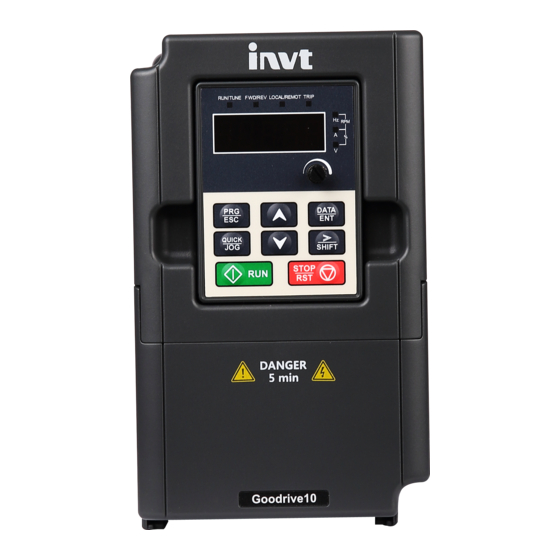
Устройство преобразователя
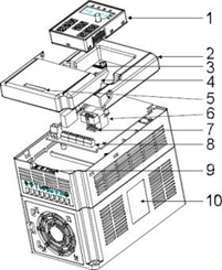
| No. | Наименование | Иллюстрация |
| 1 | Клавиатура | См. Процедура работы с клавиатурой, где приводятся подробные сведения |
| 2 | Крышка | Защита внутренних деталей и компонентов |
| 3 | Индикатор POWER | Индикатор POWER |
| 4 | Боковая крышка | Защита внутренних компонентов |
| 5 | Простая паспортная табличка | См. Ключ обозначения типа, где приводятся подробные сведения |
| 6 | Разъем клавиатуры | Подключение клавиатуры |
| 7 | Клеммы управления | См. Электрическая установка, где приводятся подробные сведения |
| 8 | Клеммы главной цепи | См. Электрическая установка, где приводятся подробные сведения |
| 9 | Ввод кабеля главной цепи | Закрепите главный силовой кабель |
| 10 | Паспортная табличка | См. Описание изделия, где приводятся подробные сведения |
Схема подключения
Схема подключения силовой цепи
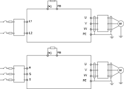
Клеммы силовых цепей
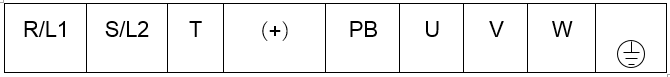
| Обозначение клеммы | Название клеммы | Функция |
| L1/R , L2/S , T | Силовой ввод сети питания | 3-фазные/однофазные входные клеммы переменного тока, которые обычно подключены к сети. |
| U , V , W | Выход ПЧ | 3-фазные выходные клеммы переменного тока, которые обычно подключены к двигателю. |
| PB , (+) | Клемма тормозного резистора | PB и (+) подключены к внешнему резистору. |
| Клемма заземления | Каждый агрегат оснащен стандартной клеммой защитного заземления. |
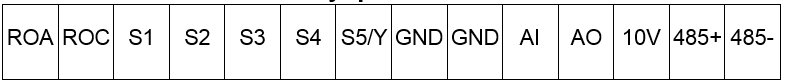
Схема подключения цепей управления

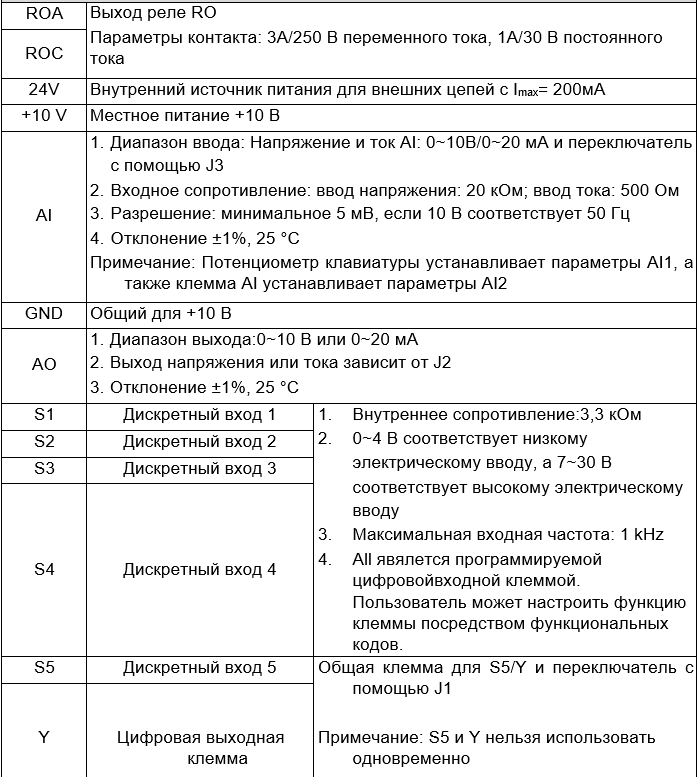
Клеммы цепей управления
Программирование параметров преобразователя
Функциональные параметры ПЧ серии GD10 разделены на 30 групп (P00 ~ P29) в соответствии с зарезервированными функциями P18 ~ P28. Каждая функциональная группа содержит определенные функциональные коды, используемые в 3-уровневом меню. Например, «P08.08» означает восьмой код функции в группе функций 8, группа 29 защищена на заводе, и пользователям отказано в доступе к этим параметрам.
Примечание: полный список параметров доступен в файле в конце страницы.
| Код | Имя | Подробное описание параметров | Значени е по умолчан ию |
| P00.00 | Режим управления скоростью | 2:Режим управления U/F 2 подходит в тех случаях, когда не нужна высокая точность регулирования, для вентиляторов и насосов. | 2 |
| P00.01 | Выбор задания команды «Пуск» | Выберите задание команды «Пуск» ПЧ. Команда управления ПЧ включает: пуск, останов, вперед, реверс, толчковый режим и сброс ошибки. 0:Команда «Пуск» с панели управления Команды RUN , STOP/RST выполняются с панели управления. Установите функцию «Реверс» для кнопок QUICK/JOG или ВПЕРЕД/НАЗАД (P07.02=3), чтобы изменить направление вращения; нажмите кнопки RUNиSTOP/RSTдля останова ПЧ в режиме работы. 1:Команда «Пуск» от клемм (индикатор “ПАНЕЛЬ/КЛЕММЫ” мигает) С помощью клемм I/O производится управления командами «Пуск», вращение вперед, реверс и толчковый режим. 2:Команда «Пуск» через протокол связи (индикатор “ПАНЕЛЬ/КЛЕММЫ” горит); Команда «Пуск» может выполняется от PLC через протокол связи |
0 |
| P00.03 | Максимальна я выходная частота | Этот параметр используется для задания максимальной выходной частоты ПЧ. Диапазон уставки: P00.04~400.00 Гц | 50.00 Гц |
| P00.04 | Верхний предел выходной частоты | Верхний предел выходной частоты ПЧ, который меньше или равен максимальной выходной частоте. Диапазон уставки: P00.05~P00.03 (Максимальная выходная частота) | 50.00 Гц |
| P00.05 | Нижний предел выходной частоты | Нижний предел выходной частоты – это минимальная выходная частота ПЧ. Примечание: Максимальная выходная частота ≥ Верхний предел частоты ≥ Нижний предел частоты Диапазон уставки: 0.00 Гц~P00.04 (Верхний предел частоты) | 0.00 Гц |
| P00.06 | А – Выбор задания частоты | 0:Задание с панели управления Измените значение кода функции P00.10 (задание частоты, панель управления) для изменения частоты с панели управления. | 0 |
| P00.07 | B – Выбор задания частоты | 1: Аналоговый вход AI1 2: Аналоговый вход AI2 6: Режим «Многоступенчатая скорость» Смотрите описание функций в группе P10 для подробной информации. 7: PID Смотрите описание функций в группе P09 PID. 8: MODBUS Частота задается по протоколу MODBUS. Подробную информацию смотрите в группе P14. Примечание: Частота A и частота B не может иметь одно и то же значение частоты в данном методе. |
| P00.08 | Частота B – выбор задания | 0: Максимальная выходная частота, 100% частоты В соответствуют максимальной выходной частоте. 1: 100% частоты А соответствуют максимальной выходной частоте. | 0 |
| P00.09 | Сочетание типа и источника задания частоты | 0: A, текущее значение частоты A- заданная частота 1: B, текущее значение частоты В — заданная частота 2: A+B, текущее значение частоты A+ частота B 3: A-B, текущее значение частоты A- частота B 4: Max (A, B): Большей между частотой А и частотой В является заданная частота. 5: Min (A, B): Меньше между частотой А и частотой В является заданная частота. | 0 |
| P00.10 | Задание частоты с панели управления | Когда частоты А или В выбраны как «Задание с панели управления», этот параметр будет иметь начальное значение опорной частоты ПЧ Диапазон уставки: 0.00 Гц~P00.03 | 50.00Гц |
| P00.11 | Время разгона ACC 1 |
Время разгона ACC 1 необходимое для разгона от 0 Гц до максимальной частоты (P00.03). Время торможения DEC 1 необходимое для останова от максимальной частоты до 0 Гц (P00.03). В ПЧ серии GD10 определены четыре группы времени разгона/торможения ACC /DEC, которые могут быть выбраны в P05. Время разгона/торможения ACC /DEC по умолчанию установлено в первой группе. Настройка диапазона P00.11 и P00.12:0.0 ~ 3600.0 сек |
0.1 |
| P00.12 | Время торможения DEC 1 |
Время разгона ACC 1 необходимое для разгона от 0 Гц до максимальной частоты (P00.03). Время торможения DEC 1 необходимое для останова от максимальной частоты до 0 Гц (P00.03). В ПЧ серии GD10 определены четыре группы времени разгона/торможения ACC /DEC, которые могут быть выбраны в P05. Время разгона/торможения ACC /DEC по умолчанию установлено в первой группе. Настройка диапазона P00.11 и P00.12:0.0 ~ 3600.0 сек |
| P00.16 | Выбор функции AVR | 0:Выключено 1:Включено во время работы Функция автоматической регулировки напряжения (AVR) обеспечивает стабильность напряжения на выходе ПЧ независимо от изменения напряжения шины постоянного тока. Во время торможения, если функция AVR выключена, и время торможения задано малым, но ток может быть большим. Если функция AVR включена всегда, время торможения будет таким, чтобы ток был номинальным. | 1 |
| P00.18 | Функция восстановлен ия параметров | 0: Выключено 1: Восстановить значения по умолчанию 2: Стирание истории ошибок Примечание: По завершению процедуры параметр функции восстанавливается на 0 автоматически. Восстановление значений по умолчанию, отменит пароль пользователя, используйте эту функцию с осторожностью |
0 |
| P01.00 | Режим «Пуск» | 0: Прямой пуск со стартовой частоты P01.01 1: Пуск после торможения DC-током: запустите двигатель от стартовой частоты после торможения DC-током (параметры P01.03 и P01.04). Этот режим подходит для двигателей с малоинерционной нагрузкой, которые могут изменить направление вращения при пуске. | 0 |
| P01.01 | Стартовая частота при пуске | Стартовая частота при пуске означает частоту, на которой будет запушен ПЧ. Диапазон уставки: 0.00~50.00 Гц | 1.50 Гц |
| P01.02 | Время работы на стартовой частоты | Определяет время работы на стартовой частоте. Установите стартовую частоту ПЧ, для увеличения крутящего момента во время запуска. Во время сохранения исходной частоты выходная частота ПЧ является стартовой частотой. И затем, ПЧ будет выходить со стартовой частоты на заданную частоту. Если задать частоту ниже стартовой частоты, то ПЧ будет остановлен, и находиться в дежурном состоянии. Стартовая частота не ограничена нижним пределом частоты. | 0.0 сек |
| P01.05 | Выбор разгона/тормо же- ния ACC/DEC | Изменение режима частоты во время пуска и работы. 0: Линейная Выходная частота увеличивается или уменьшается линейно. | 0 |
| P01.08 | Выбор режима останова | 0: Останов с замедлением: После активации команды останова преобразователь частоты уменьшает выходную частоту в соответствии с установленным временем разгона/торможения. Когда частота уменьшается до 0, ПЧ останавливается 1: Останов с выбегом: После активации команды останова двигатель останавливается в результате свободного инерционного вращения |
0 |
| P01.14 | Переключени е ВПЕРЕД/НАЗ АД | Установите пороговую точку ПЧ: 0: Переключение при 0 частоте 1: Переключение после стартовой частоты | 0 |
| P01.15 | Скорость при останове | 0.00~100.00 Гц | 1.00 Гц |
| P01.21 | Перезапуск после выключения питания | Эта функция может приводить к автоматическому повторному включению ПЧ, будьте аккуратны. 0: Отключено 1: Включено, ПЧ будет запускаться автоматически после времени ожидания определенного в P01.22. | 0 |
| P01.22 | Время ожидания перезапуска после отключения питания | Функция определяет время ожидания до автоматического запуска ПЧ, когда он выключен и затем включен. | 1.0 сек |
| P01.23 | Время задержки пуска | Функция определяет время задержки перед запуском ПЧ установленное в P01.23 Диапазон уставки: 0.0~60.0 сек | 0.0 сек |
| P01.24 | Время задержки останова | Диапазон уставки: 0.0~100.0 сек | 0.0 сек |
| P02.01 | Асинхронный двигатель 1 номинальная мощность | 0.1~2.2 кВт | Зависит от типа двигател я |
| P02.02 | Асинхронный двигатель 1 номинальная частота | 0.01Гц~P00.03 (Максимальная частота) | 50.00Гц |
| P02.03 | Асинхронный двигатель 1 номинальная скорость | 1~36000 об/мин | Зависит от типа двигател я |
| P02.04 | Асинхронный двигатель 1 номинальное напряжение | 0~400 В | Зависит от типа двигател я |
| P02.05 | Асинхронный двигатель 1 номинальный ток | 0.8~5.5 A | Зависит от типа |
| P02.06 | Асинхронный двигатель 1 сопротивлени е статора | 0.001~65.535 Ом | Зависит от типа двигател я |
| P02.07 | Асинхронный двигатель 1 сопротивлени е ротора | 0.001~65.535 Ом | Depend on module |
| P02.08 | Асинхронный двигатель 1 индуктивность | 0.1~6553.5 мГн | Зависит от типа двигател я |
| P02.09 | Асинхронный двигатель 1 взаимная индуктивность | 0.1~6553.5 мГн | Зависит от типа двигател я |
| P02.10 | Асинхронный двигатель 1 ток нагрузки | 0.1~5.5 A | Зависит от типа двигател я |
| P02.26 | Выбор защиты двигателя 1 при перегрузке | 0: Нет защиты 1: Обычный двигатель (компенсация при работе с низкой скоростью). Потому что тепловой эффект обычных двигателей будет ослаблен, и соответствующая электрическая тепловая защита будет скорректирована надлежащим образом. Характеристика компенсации на низкой скорости означает уменьшение порога защиты от перегрузки электродвигателя, при работе на частоте меньше 30 Гц. 2: Двигатели с частотным регулированием (без компенсации при работе на низкой скорости). | 2 |
| P04.00 | Двигатель 1 Настройка кривой U/F | 0: Линейная кривая U/F; постоянный крутящий момент нагрузки 1: Многоточечная кривая U/F | 0 |
| P04.01 | Усиление крутящего момента | Усиление крутящего момента по отношению к выходному напряжению. | 0.0% |
| P05.01-P05.05 | Выбор функции клеммы входа S1 — S5 | 0: Нет функции 1: Пуск «Вперед» 2: «Реверс» 3: 3-х проводное управление 4: «Вперед» толчковый режим 5: «Реверс» толчковый режим 6: Останов с выбегом 7: Сброс ошибки 8: Пауза в работе 9: Вход «Внешняя неисправность» 10: Увеличение частоты (UP) (псевдо-потенциометр) 11: Уменьшение частоты (DOWN) (псевдо-потенциометр) 12: Отмена изменения частоты 13:Переход между уставкой A и уставкой B 14:Переход от комбинации уставок к уставке А 15: Переход от комбинации уставок к уставке В 16:Многоступенчатая скорость клемма 1 17:Многоступенчатая скорость клемма 2 18:Многоступенчатая скорость клемма 3 19:Многоступенчатая скорость клемма 4 20:Многоступенчатая скорость — пауза 21:Время разгона/торможения ACC/DEC 1 25:Пауза в управлении PID 26:Пауза перехода (останов на текущей частоте) 27:Сброс (возврат к центральной частоте) 28: Сброс счетчика 30: Запрет разгона/торможения ACC/DEC 31: Счетчик триггера 33: Отмена параметра временного изменения частоты 34:DC торможение 36:Переход на управление от панели управления 37:Переход на управление от клемм 38:Переход на управление по протоколам связи |
— |
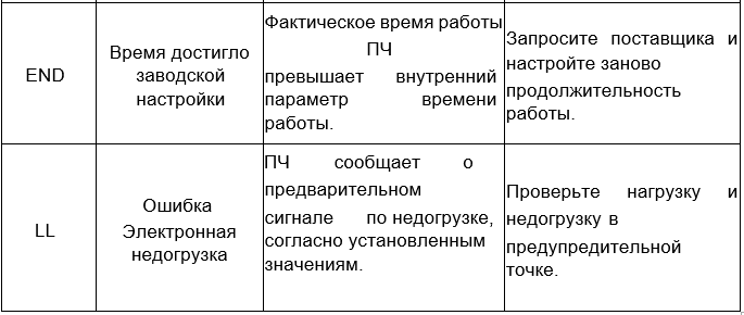
Список возможных ошибок
Сделайте следующие после появления ошибки ПЧ:
- Убедитесь в том, что панель управления работает и есть индикация. Если нет, пожалуйста, свяжитесь с местным отделением INVT.
- Если все в порядке, то проверьте параметр P07 и обеспечьте соответствующие параметры зарегистрированных неисправностей для подтверждения реального состояния, при текущей неисправности по всем параметрам.
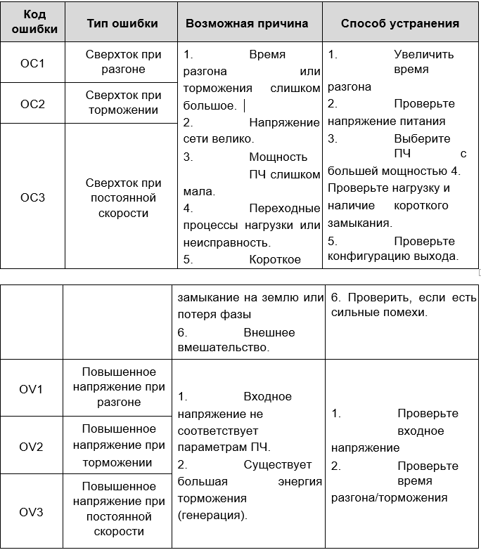
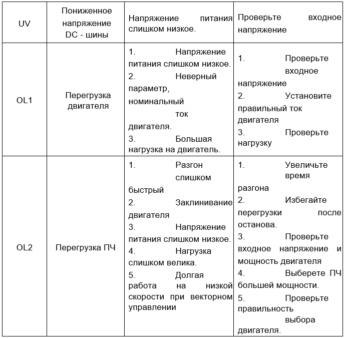
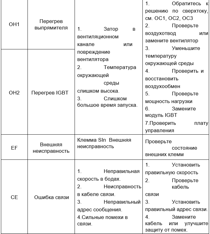
- В следующей таблице приведены описания ошибок (неисправностей) и методы их устранения.
- Устраните ошибку (неисправность).
- Проверьте, чтобы неисправность была устранена и осуществлите сброс ошибки (неисправности) для запуска ПЧ.
Скачать полную документацию.
RU
Преобразователь частоты GD 10 с эргономичным дизайном, съёмной панелью и встроенным ЕМС-фильтром класса С2 предназначен для электроприводов малой мощности и вентиляционных систем.Прост в управлении, обладает высокой производительностью и функциональностью.
Отличительные особенности:
Надежность
Компактность
Простота в управлении
Многоступенчатая скорость (16 скоростей)
Встроенный тормозной блок
Съемная панель
ПИД регулятор
Интерфейс 485(Modbus)
Встроенным ЕМС-фильтром (класс С2)
Съемная панель
Краткая информация о преобразователе частоты GD 10
Малогабаритный и экономичный преобразователь частоты GD10 спроектирован специально для изготовителей оборудования (OEM). Этот преобразователь частоты имеет улучшенное скалярное управление, функцию ПИД-регулирования, режим фиксированных скоростей, торможение постоянным током, встроенный коммуникационный протокол Modbus и многие другие преимущества. К тому же он требует намного меньше установочного места.<
Преимущества инверторов серии GD 10
— Скалярное управление (U/F)
 серия GD 10")
— Естественное охлаждение (для установки в запыленных помещения)
")
— Экономия места за счет компактных размеров
— Выносная LED панель управления с потенциометром

— Продукция соответствует стандартам IEC GB и имеет сертификат СЕ
— Широкий набор функций управления электродвигателем
Схема подключения частотных преобразователей серии GD 10

-
Contents
-
Table of Contents
-
Bookmarks
Quick Links
Related Manuals for INVT Goodrive10 Series
Summary of Contents for INVT Goodrive10 Series
-
Page 2: Table Of Contents
Goodrive10 VFDs Contents Contents Contents …………………………..i Chapter 1 Safety precautions ……………………. 1 1.1 Safety definition ………………………. 1 1.2 Warning signs ……………………….1 1.3 Safety guidelines ……………………..2 Chapter 2 Product overview ……………………… 4 2.1 Quick start ……………………….4 2.2 Product specifications……………………… 5 2.3 Nameplate ……………………….
-
Page 3
C.4 Breaker and electromagnetic contactor ………………..98 C.5 Reactors ……………………….99 C.6 Filter …………………………100 C.7 Braking system ……………………..103 Appendix D Further information …………………… 105 D.1 Product and service inquiries ………………….105 D.2 Feedback on INVT VFD manuals………………… 105 D.3 Online document library ……………………105… -
Page 4: Chapter 1 Safety Precautions
Goodrive10 VFDs Safety precautions Chapter 1 Safety precautions Read this manual carefully and follow all safety precautions before moving, installing, operating and servicing the variable-frequency drive (VFD). If ignored, physical injury or death may occur, or damage may occur to the devices. If any physical injury or death or damage to the devices occurs for ignoring to the safety precautions in the manual, our company will not be responsible for any damages and we are not legally bound in any manner.
-
Page 5: Safety Guidelines
Goodrive10 VFDs Safety precautions 1.3 Safety guidelines Only qualified electricians are allowed to operate on the VFD. Do not carry out any wiring and inspection or changing components when the power supply is applied. Ensure all input power supply is disconnected before wiring and checking and always wait for at least the time designated on the VFD or until the DC bus voltage is less than 36V.
-
Page 6
Goodrive10 VFDs Safety precautions 1.3.2 Commissioning and running Disconnect all power supplies applied to the VFD before the terminal wiring and wait for at least the designated time after disconnecting the power supply. High voltage is present inside the VFD during running. Do not carry out any operation except for the keypad setting. -
Page 7: Chapter 2 Product Overview
4. Check the information on the type designation label on the outside of the package to verify that the nameplate is of the correct type. If not, please contact with local dealers or INVT offices. 5. Check to ensure the accessories (including user’s manual and control keypad) inside the device is complete.
-
Page 8: Product Specifications
Goodrive10 VFDs Product overview 2.1.4 Installation confirmation Check as followings after the installation: 1. Check that the load range of the input and output cables meet the need of actual load. 2. Check that the accessories of the VFD are correctly and properly installed. The installation cables should meet the needs of every component (including reactors, input filters, output reactors, output filters, DC reactors and braking resistors).
-
Page 9
Goodrive10 VFDs Product overview Function Specification Adjustable-speed ratio 1:100 150% of rated current: 1 minute Overload capability 180% of rated current: 10 seconds 200% of rated current: 1 second Key functions Stop mode and anti-overtemperature of the bus Temperature Overtemperature point ± 3° C measurement accuracy Terminal switch input ≤… -
Page 10: Nameplate
Made in china Shenzhen INVT Electric Co., Ltd. Figure 2-1 Nameplate Note: Figure 2-1 shows an example of a Goodrive10 series VFD namplate. The CE, TUV, or IP rating is labelled according to product certification. 2.4 Type designation key The type designation contains information on the VFD. The user can find the type designation on the type designation label attached to the VFD or the simple nameplate.
-
Page 11: Structure Diagram
Goodrive10 VFDs Product overview Model Output power(kW) Input current(A) Output current (A) GD10-2R2G-S2-B GD10-0R2G-2-B GD10-0R4G-2-B Three-phase GD10-0R7G-2-B 0.75 220V GD10-1R5G-2-B GD10-2R2G-2-B GD10-0R7G-4-B 0.75 Three-phase GD10-1R5G-4-B 380V GD10-2R2G-4-B 2.6 Structure diagram Figure 2-3 shows the structure of the VFD (takeing the VFD of 2.2kW as an example). Figure 2-3 Product structure diagram Name Illustration…
-
Page 12
Goodrive10 VFDs Product overview Name Illustration information. To connect the keypad. Keypad port 6 is for external installation. Control circuit terminals See section 3.2 «Electrical installation» for detailed information. To protect the internal parts and components, detachable for Bobbin winder wiring Main circuit terminals See section 3.2 «Electrical installation»… -
Page 13: Chapter 3 Installation
Goodrive10 VFDs Installation Chapter 3 Installation The chapter describes the mechanical installation and electrical installation. Only qualified electricians are allowed to carry out what described in this chapter. Please operate as the instructions in Safety Precautions. Ignoring these may cause physical injury or death or damage to the devices.
-
Page 14
The VFD should be installed on an upright position to ensure sufficient Installation direction cooling effect. Note: • Goodrive10 series VFDs should be installed in a clean and ventilated environment according to enclosure classification. • Cooling air must be clean, free from corrosive materials and electrically conductive dust. 3.1.2 Installation direction The VFD may be installed on the wall or in a cabinet. -
Page 15: Electrical Installation
Goodrive10 VFDs Installation (1) Mark the hole location. The location of the holes is shown in the dimension drawings in the appendix. (2) Fix the screws or bolts to the marked locations. (3) Position the drive onto the wall. (4) Tighten the screws in the wall securely. A.1.1 Installation space Warm air Cool air…
-
Page 16
Goodrive10 VFDs Installation terminal blocks. Otherwise, poor connection may occur. 3.2.2 Terminals figure of main circuit Figure 3-4 Terminals of main circuit Terminal Terminal name Function sign 3-phase/single-phase AC input terminals which are generally Power input of the main circuit connected with the grid. -
Page 17
Goodrive10 VFDs Installation 3.2.4 Connection diagram of the control circuit Multi-function input terminal 1 Analog output Multi-function input terminal 2 0-10V/0-20mA Multi-function input terminal 3 Multi-function input terminal 4 Open collector output Multi-function input terminal 5 S5/Y Twisted pairs Shielding wire 485+ RS485 485-… -
Page 18: Wiring Protection
Goodrive10 VFDs Installation 3. Deviation± 1%, 25° C 1. Internal impedance:3.3kΩ Switch input 1 2. 0–4V corresponds to low electric level input and 7–30V corresponds to high electric level input Switch input 2 3. Max input frequency:1kHz Switch input 3 4.
-
Page 19
Goodrive10 VFDs Installation In some special situations, for example, if it is only used in soft start, the VFD can be conversed into power frequency running after starting and some corresponding bypass should be added. Never connect the supply power to the VFD output terminals U, V and W. Power line voltage applied to the output can result in permanent damage to the VFD. -
Page 20: Chapter 4 Keypad
4.1 Keypad description The keypad is used to control Goodrive10 series VFDs, read the state data and adjust parameters. If you need to use the keypad in another place rather than on the VFD, use a network cable with a standard RJ45 crystal head as the extension cable.
-
Page 21
Goodrive10 VFDs Keypad Name Description Frequency unit Current unit Voltage unit Rotating speed unit Percentage 5-figure LED display displays various monitoring data and alarm code such as set frequency and output frequency. Displayed Corresponding Displayed Corresponding Displayed Corresponding word word word word word… -
Page 22: Keypad Display
Quick key P07.02. 4.2 Keypad display The keypad displaying state of Goodrive10 series VFDs is divided into stopping state parameter, running state parameter, function code parameter editing state and fault alarm state and so on. 4.2.1 Displayed state of stopping parameter When the VFD is in the stopping state, the keypad will display stopping parameters which is shown in figure 4-2.
-
Page 23: Keypad Operation
Goodrive10 VFDs Keypad FWD/REV LOCAL/REMOT FWD/REV LOCAL/REMOT FWD/REV LOCAL/REMOT RUN/TUNE TRIP RUN/TUNE TRIP RUN/TUNE TRIP DATA DATA DATA QUICK QUICK QUICK SHIFT SHIFT SHIFT STOP STOP STOP Parameter displayed in Parameter displayed Information displayed the stop state in the running state in the faulty state Figure 4-2 Displayed states 4.3 Keypad operation…
-
Page 24
Figure 4-4 Sketch map of password setting 4.3.3 How to view the VFD state through function codes Goodrive10 series VFDs provide group P17 as the state inspection group. Users can enter into P17 directly to watch the state. The units place is blinking. -
Page 25: Chapter 5 Function Parameters
Function parameters Chapter 5 Function parameters The function parameters of Goodrive10 series VFDs have been divided into 30 groups (P00–P29) according to the function, of which P18–P28 are reserved. Each function group contains certain function codes applying 3-level menus. For example, “P08.08” means the eighth function code in the P8 group function, P29 group is factory reserved, and users are forbidden to access these parameters.
-
Page 26
Goodrive10 VFDs Function parameters Function Default Name Detailed description of parameters Modify code value 1:Terminal running command channel (“ LOCAL/REMOT” flickering) Carry out the running command control by the forward rotation, reverse rotation and forward jogging and reverse jogging of the multi-function terminals 2:Communication running command… -
Page 27
Goodrive10 VFDs Function parameters Function Default Name Detailed description of parameters Modify code value be switched by the jumper. Note: when AI2 selects 0–20mA input, 20mA corresponds to 10V. 100.0% of the analog input corresponds to P00.03, -100.0% of the analog input corresponds to the reverse P00.03. -
Page 28
0Hz to the Max. One (P00.03). on model DEC time means the time needed if the VFD speeds down from the Max. Output frequency to 0Hz (P00.03). Goodrive10 series VFDs define four groups of ACC/DEC Depend ○ P00.12 DEC time 1 time which can be selected by P05. -
Page 29
Goodrive10 VFDs Function parameters Function Default Name Detailed description of parameters Modify code value Carrier Electro magnetic Noise and leakage Heating frequency noise current eliminating 1kHz High 10kHz 15kHz High High The advantage of high carrier frequency: ideal current waveform, little current harmonic wave and motor noise. The disadvantage of high carrier frequency: increasing the switch loss, increasing VFD temperature and the impact to the output capacity. -
Page 30
Goodrive10 VFDs Function parameters Function Default Name Detailed description of parameters Modify code value P01 group Start and stop control 0:Start-up directly:start from the starting frequency P01.01 1:Start-up after DC braking: start the motor from the starting ◎ P01.00 Start mode frequency after DC braking (set the parameter P01.03 and P01.04). -
Page 31
Goodrive10 VFDs Function parameters Function Default Name Detailed description of parameters Modify code value Setting range of P01.04: 0.0–50.0s The changing mode of the frequency during start-up and running. 0:Linear type The output frequency increases or decreases linearly. Output frequency ACC/DEC ◎… -
Page 32
Goodrive10 VFDs Function parameters Function Default Name Detailed description of parameters Modify code value P01.09 P1315 Constant speed P01.04 P1314 P01.12 P0110 P0123 In running Setting range of P01.09: 0.00Hz–P00.03 Setting range of P01.10: 0.0–50.0s Setting range of P01.11: 0.0–100.0% Setting range of P01.12: 0.0–50.0s During the procedure of switching FWD/REV rotation, set the threshold by P01.14, which is as the table below:… -
Page 33
Goodrive10 VFDs Function parameters Function Default Name Detailed description of parameters Modify code value 1: The terminal running command is valid when powering on. If the running command is detected to be valid during powering on, the system will start the VFD automatically after the initialization. -
Page 34
Goodrive10 VFDs Function parameters Function Default Name Detailed description of parameters Modify code value after power off powering on. Output frequency f t1=P01.22 Time t Running Running Powered off Powered on Setting range: 0.0–3600.0s (valid when P01.21=1) The function determines the brake release after the running command is given, and the VFD is in a stand-by state and ○… -
Page 35
Goodrive10 VFDs Function parameters Function Default Name Detailed description of parameters Modify code value Asynchronous Depend ○ P02.06 motor stator 0.001–65.535Ω on model resistor Asynchronous Depend ○ P02.07 motor rotor 0.001–65.535Ω on model resistor Asynchronous Depend ○ P02.08 motor leakage 0.1–6553.5mH on model inductance… -
Page 36
Goodrive10 VFDs Function parameters Function Default Name Detailed description of parameters Modify code value coefficient So, the bigger the overload coefficient is, the shorter the reporting time of the overload fault is. When the overload coefficient <110%, there is no overload protection. When M=116%, protection is performed after motor overload lasts for 1 hour;… -
Page 37
Goodrive10 VFDs Function parameters Function Default Name Detailed description of parameters Modify code value torque boost. Torque boost threshold: below this frequency point, the torque boost is valid, but over this frequency point, the torque boost is invalid. Output voltage Output boost frequency… -
Page 38
Goodrive10 VFDs Function parameters Function Default Name Detailed description of parameters Modify code value This function code is used to compensate the change of the rotation speed caused by load during compensation 380V: SVPWM control to improve the rigidity of the motor. It can 100.0% be set to the rated slip frequency of the motor which is counted as below:… -
Page 39
Goodrive10 VFDs Function parameters Function Default Name Detailed description of parameters Modify code value S3 terminal 6: Coast to stop ◎ P05.03 function 7: Fault reset selection 8: Operation pause 9: External fault input S4 terminal 10:Increasing frequency setting(UP) ◎ P05.04 function 11:Decreasing frequency setting(DOWN) -
Page 40
Goodrive10 VFDs Function parameters Function Default Name Detailed description of parameters Modify code value Enable the input function of virtual terminals at the Virtual communication mode. ◎ P05.12 terminals 0:Virtual terminals is invalid setting 1:MODBUS communication virtual terminals are valid Set the operation mode of the terminals control 0:2-wire control 1, comply the enable with the direction. -
Page 41
Goodrive10 VFDs Function parameters Function Default Name Detailed description of parameters Modify code value 3:3-wire control 2; Sin is the enabling terminal on this mode, if set Si (i=1–5) to 3, when K is switched on, the control of FWD and REV is valid; when K is switched off, the control of FWD and REV is invalid. -
Page 42
Goodrive10 VFDs Function parameters Function Default Name Detailed description of parameters Modify code value S2 terminal Si electrical level ○ 0.000s P05.16 switching on delay time Si valid invalid valid invalid Switcn-on Switcn-off delay delay terminal ○ 0.000s P05.17 Setting range:0.000–50.000s switching off delay time S3 terminal… -
Page 43
Goodrive10 VFDs Function parameters Function Default Name Detailed description of parameters Modify code value Upper limit of corresponding voltage of 0–20mA is 0–10V. ○ 10.00V P05.34 In different cases, the corresponding rated value of 100.0% is different. See the application for detailed information. Corresponding The figure below illustrates different applications: setting of… -
Page 44
Goodrive10 VFDs Function parameters Function Default Name Detailed description of parameters Modify code value 6:Frequency degree test FDT1 7:Frequency degree test FDT2 8:Frequency arrival 9:Zero speed running 10:Upper limit frequency arrival 11:Lower limit frequency arrival 12:Ready for operation 14:Overload pre-alarm 15: Underload pre-alarm 16:Completion of simple PLC stage 17:Completion of simple PLC cycle… -
Page 45
Goodrive10 VFDs Function parameters Function Default Name Detailed description of parameters Modify code value 1:Set frequency 2:Ramp reference frequency 3:Running rotation speed (relative to twice the rotating speed of the motor) 4:Output current (relative to twice the rated current of the VFD) 5:Output current (relative to twice the rated current of the motor) -
Page 46
Goodrive10 VFDs Function parameters Function Default Name Detailed description of parameters Modify code value Setting range of P06.20 0.00V–10.00V Setting range of P06.21 0.000s–10.000s P07 group Human-machine interface 0–65535 The password protection will be valid when setting any non-zero number. 00000: Clear the previous user’s password, and make the password protection invalid. -
Page 47
Goodrive10 VFDs Function parameters Function Default Name Detailed description of parameters Modify code value non-factory parameter) Note: Press QUICK/JOG to shift between forward rotation and reverse rotation, the VFD does not record the state after shifting during powering off. The VFD will run according to parameter P00.13 during next powering on. -
Page 48
Goodrive10 VFDs Function parameters Function Default Name Detailed description of parameters Modify code value 0x0000–0xFFFF BIT0: analog AI1 value (V on) The parameter BIT1: analog AI2 value (V on) 0x0000 P07.06 selection 2 of BIT4: motor overload percentage (% on) running state BIT5: the VFD overload percentage (% on) BIT6: ramp frequency reference value(Hz on) -
Page 49
Goodrive10 VFDs Function parameters Function Default Name Detailed description of parameters Modify code value Local ● P07.14 accumulative 0–65535h running time The rated ● P07.18 power of the 0.4–3000.0kW The rated ● P07.19 voltage of the 50–1200V The rated ● P07.20 current of the 0.1–6000.0A… -
Page 50
Goodrive10 VFDs Function parameters Function Default Name Detailed description of parameters Modify code value 6:OC3 7:OV1 Previous fault ● P07.28 type 8:OV2 9:OV3 10:UV Previous 2 fault 11:Motor overload (OL1) ● P07.29 type 12: VFD overload (OL2) 15:Overheat of the rectifier module(OH1) Previous 3 fault ●… -
Page 51
Goodrive10 VFDs Function parameters Function Default Name Detailed description of parameters Modify code value state at current fault Output terminal ● P07.40 state at current fault Previous fault ● 0.00Hz P07.41 running frequency Ramp reference ● 0.00Hz P07.42 frequency at previous fault Output voltage ●… -
Page 52
○ Refer to P00.11 and P00.12 for detailed definition. P08.00 ACC time 2 on model Goodrive10 series define four groups of ACC/DEC time which can be selected by P5 group. The first group of Depend ○ P08.01 DEC time 2 ACC/DEC time is the factory default one. -
Page 53
Goodrive10 VFDs Function parameters Function Default Name Detailed description of parameters Modify code value Setting range:0.0–3600.0s Jogging This parameter is used to define the reference frequency ○ P08.06 running during jogging. 5.00Hz Setting range: 0.00Hz –P00.03(the Max. frequency) frequency Jogging Depend ○… -
Page 54
Goodrive10 VFDs Function parameters Function Default Name Detailed description of parameters Modify code value The declining time of the traverse frequency: The time from the highest point to the lowest one. Setting range of P08.15: 0.0–100.0%(relative to the set frequency) Setting range of P08.16: 0.0–50.0%(relative to the traverse range) Setting range of P08.17: 0.1–3600.0s… -
Page 55
Goodrive10 VFDs Function parameters Function Default Name Detailed description of parameters Modify code value Setting range of P08.28:0–10 Setting range of P08.29:0.1–3600.0s FDT electrical When the output frequency exceeds the corresponding ○ 50.00Hz P08.32 level detection frequency of FDT electrical level, the multi-function digital output terminals will output the signal of “frequency level value detect FDT”… -
Page 56
Goodrive10 VFDs Function parameters Function Default Name Detailed description of parameters Modify code value This parameter is used to control the internal braking pipe. Energy Braking 0:Disabled ○ P08.37 enable 1:Enabled Note: Only applied to internal braking pipe. 220V After setting the original bus voltage to brake the energy, voltage: adjust the voltage appropriately to brake the load. -
Page 57
Goodrive10 VFDs Function parameters Function Default Name Detailed description of parameters Modify code value 0:Setting is valid 1:Valid during running, cleared after stopping 2:Valid during running, cleared after receiving the stop command LED thousands: ∧/∨ keys and digital potentiometer Integral function 0:The Integral function is valid 1:The Integral function is invalid 0x00–0x221… -
Page 58
Goodrive10 VFDs Function parameters Function Default Name Detailed description of parameters Modify code value LED hundreds: Action for other-mode frequency setting on power off 0: Save on power off 1: Clear on power off This function code is used to enable magnetic flux. 0: Invalid. -
Page 59
Goodrive10 VFDs Function parameters Function Default Name Detailed description of parameters Modify code value preset the feedback value of the system. Setting range:-100.0%–100.0% Select the PID channel by the parameter. PID feedback 1:Analog channel AI2 feedback ○ P09.02 source 4:MODBUS communication feedback selection Note: The reference channel and the feedback channel can not coincide, otherwise, PID can not control validly. -
Page 60
Goodrive10 VFDs Function parameters Function Default Name Detailed description of parameters Modify code value (P00.03). Longer the integral time, stronger is the adjusting. Setting range: 0.00–10.00s This parameter means the sampling cycle of the feedback. Sampling The modulator calculates in each sampling cycle. The ○… -
Page 61
Goodrive10 VFDs Function parameters Function Default Name Detailed description of parameters Modify code value Output frequency t1 < t2, so the VFD continues to run t2 = P09.12 PIDE P09.11 In running Fault output PIDE Setting range of P09.11: 0.0–100.0% Setting range of P09.12: 0.0–3600.0s 0x00–0x11 LED ones:… -
Page 62
Multi-step ○ 0.0% P10.10 –f Multi-step speeds are in the range of —f and it can speed 4 Multi-step Goodrive10 series VFDs can set 16 steps speed, selected ○ 0.0% P10.12 speed 5 combination multi-step terminals 1–4, corresponding to the speed 0 to speed 15. -
Page 63
Goodrive10 VFDs Function parameters Function Default Name Detailed description of parameters Modify code value Terminal OFF ON OFF ON OFF ON OFF ON Terminal OFF OFF ON ON OFF OFF ON ON Terminal OFF OFF OFF OFF ON ON ON ON Terminal OFF OFF OFF OFF OFF OFF OFF OFF Step… -
Page 64
Goodrive10 VFDs Function parameters Function Default Name Detailed description of parameters Modify code value caused by VFD protection during the switching of the grid. 2. Disable input phase loss protection to enable this function. 0:Disabled 1:Enabled DC bus voltage Overvoltage Overvoltage stall point ○… -
Page 65
Goodrive10 VFDs Function parameters Function Default Name Detailed description of parameters Modify code value 0:current limit invalid 1:current limit valid Setting range of P11.06:50.0–200.0% Setting range of P11.07:0.00–50.00Hz/s Overload The output current of the VFD or the motor is above P11.09 pre-alarm of and the lasting time is beyond P11.10, overload pre-alarm ○… -
Page 66
Goodrive10 VFDs Function parameters Function Default Name Detailed description of parameters Modify code value Setting range of P11.09: P11.11–200% Setting range of P11.10: 0.1–60.0s Detection level of the ○ P11.11 If the VFD current or the output current is lower than underload P11.11, and its lasting time is beyond P11.12, the VFD will pre-alarm… -
Page 67
Goodrive10 VFDs Function parameters Function Default Name Detailed description of parameters Modify code value Set the digital transmission speed between the upper monitor and the VFD. 0:1200BPS 1:2400BPS 2:4800BPS 3:9600BPS ○ P14.01 Baud rate 4:19200BPS 5:38400BPS Note: The baud rate between the upper monitor and the VFD must be the same. -
Page 68
Goodrive10 VFDs Function parameters Function Default Name Detailed description of parameters Modify code value When the function code is set as non-zero, if the interval time between communications exceeds communication overtime, the system will report “485 communication faults” (CE). Generally, set it as invalid; set the parameter in the continuous communication to monitor the communication state. -
Page 69
Goodrive10 VFDs Function parameters Function Default Name Detailed description of parameters Modify code value Display current output voltage of the VFD ● P17.03 Output voltage Range: 0–1200V Display current output current of the VFD ● P17.04 Output current 0.0A Range: 0.0–5000.0A The rotation Display the rotation speed of the motor. -
Page 70
Goodrive10 VFDs Function parameters Function Default Name Detailed description of parameters Modify code value Display analog AI1 input signal AI1 input ● P17.19 0.00V voltage Range: 0.00–10.00V Display analog AI2 input signal AI2 input ● P17.20 0.00V voltage Range: 0.00–10.00V Display PID reference value PID reference ●… -
Page 71: Chapter 6 Fault Tracking
This chapter describes how to perform preventive maintenance on the VFD. 6.1.1 Maintenance intervals If installed in an appropriate environment, the VFD requires very little maintenance. The table lists the routine maintenance intervals recommended by INVT. Checking part Checking item…
-
Page 72
Goodrive10 VFDs Fault tracking Checking part Checking item Checking method Criterion Ensure that there are no crackles or color-changing of Visual examination the protective layers. Ensure that there is no Terminals seat Visual examination damage Ensure that there is no weeping, color-changing, Visual examination… -
Page 73
Fan failure can be predicted by the increasing noise from the fan bearings. If the VFD is operated in a critical part of a process, fan replacement is recommended once these symptoms appear. Replacement fans are available from INVT. Read and follow the instructions in chapter Safety Precautions. Ignoring the instructions would cause physical injury or death, or damage to the equipment. -
Page 74
Change electrolytic capacitors if the working hours of electrolytic capacitors in the VFD are above 35000. Please contact with the local INVT offices or diall our national service hotline (400-700-9997) for detailed operation. -
Page 75: Fault Rectification
6.2.3 Fault instruction and solution Do as the following after the VFD fault: Check to ensure there is nothing wrong with the keypad. If not, please contact with the local INVT office. If there is nothing wrong, please check P07 and ensure the corresponding recorded fault parameters to confirm the real state when the current fault occurs by all parameters.
-
Page 76
Goodrive10 VFDs Fault tracking Over-voltage when motor or it needs to add the constant speed dynamic braking components. running The voltage of the power supply Check the input power of the DC bus Under-voltage is too low. supply line 1. The voltage of the power 1. -
Page 77
Goodrive10 VFDs Fault tracking 1. Error of controlling the write 1. Press STOP/RST to reset EEPROM fault and read of the parameters 2. Change the main control 2. Damage to EEPROM panel 1. Check the PID feedback 1. PID feedback offline signal PIDE PID feedback fault… -
Page 78: Chapter 7 Communication Protocol
Goodrive10 VFDs Communication protocol Chapter 7 Communication protocol 7.1 Modbus protocol introduction Modbus protocol is a software protocol and common language which is applied in the electrical controller. With this protocol, the controller can communicate with other devices via network (the channel of signal transmission or the physical layer, such as RS485).
-
Page 79
Goodrive10 VFDs Communication protocol Max. Max. Max. Max. Baud Baud Baud Baud transmission transmission transmission transmission rate rate rate rate distance distance distance distance 2400BPS 1800m 4800BPS 1200m 9600BPS 800m 19200BPS 600m It is recommended to use shield cables and make the shield layer as the grounding wires during RS485 remote communication. -
Page 80
Goodrive10 VFDs Communication protocol Twisted pair cables with shield screen 120 Ohm 485 + 485 + 485 + Terminal resistor 485 — 485 — 485 — Earth Earth Earth RS232-485 Conv erter Max length of RS: 15m Computer Address 1 Address 2 Address n Figure 7-2 Chrysanthemum connection applications… -
Page 81
Goodrive10 VFDs Communication protocol Check Start bit BIT1 BIT2 BIT3 BIT4 BIT5 BIT6 BIT7 End bit In a character frame, only the data bits carry information. The start bit, check bit, and end bit are used to facilitate the transmission of the data bits to the destination device. In practical applications, you must set the data bits, parity check bits, and end bits consistently. -
Page 82
Goodrive10 VFDs Communication protocol 7.2.2.2 RTU communication frame error checkout Various factors (such as electromagnetic interference) may cause error in the data transmission. For example, if the sending message is a logic “1”,A-B potential difference on RS485 should be 6V, but in reality, it may be -6V because of electromagnetic interference, and then the other devices take the sent message as logic “0”… -
Page 83: Rtu Command Code And Communication Data Description
Goodrive10 VFDs Communication protocol unsigned int crc_value=0xffff; while(data_length—) crc_value^=*data_value++; for(i=0;i<8;i++) if(crc_value&0x0001)crc_value=(crc_value>>1)^0xa001; else crc_value=crc_value>>1; return(crc_value); In ladder logic, CKSM calculated the CRC value according to the frame with the table inquiry. The method is advanced with easy program and quick calculation speed. But the ROM space the program occupied is huge. So use it with caution according to the program required space.
-
Page 84
Goodrive10 VFDs Communication protocol is in the front and the low bit is in the behind. “Data number” means the reading data number with the unit of word. If the “start address’ is 0004H and the “data number” is 0002H, the data of 0004H and 0005H will be read. CRC occupies 2 bytes with the fact that the high bit is in the front and the low bit is in the behind. -
Page 85
Goodrive10 VFDs Communication protocol Low bit of writing data address data content data content CRC CHK low bit CRC CHK high bit T1-T2-T3-T4 (transmission time of 3.5 bytes) RTU slave response message (from the VFD to the master) START T1-T2-T3-T4 (transmission time of 3.5 bytes) ADDR High bit of writing data address Low bit of writing data address… -
Page 86
Goodrive10 VFDs Communication protocol START T1-T2-T3-T4 (transmission time of 3.5 bytes) ADDR High byte of sub-function code Low byte of sub-function code High byte of data content Low byte of data content Low byte of CRC High byte of CRC T1-T2-T3-T4 (transmission time of 3.5 bytes) 7.3.4 The definition of data address The address definition of the communication data in this part is to control the running of the VFD and get the… -
Page 87
Goodrive10 VFDs Communication protocol Function Address Data meaning instruction instruction definition characteristics 0001H:forward running 0002H:reverse running 0003H:forward jogging 0004H:reverse jogging Communication 2000H 0005H:stop control command 0006H:coast to stop (emergency stop) 0007H:fault reset 0008H:jogging stop Communication setting frequency(0–Fmax(unit: 2001H 0.01Hz)) PID reference, range(0–1000, 1000 2002H corresponds to100.0% ) PID feedback, range(0–1000, 1000… -
Page 88
Goodrive10 VFDs Communication protocol Function Address Data meaning instruction instruction definition characteristics Output voltage 3003H Output current 3004H Operation speed 3005H Output power 3006H Output torque 3007H PID setting 3008H PID feedback 3009H Input IO state 300AH Output IO state 300BH AI 1 300CH… -
Page 89
Goodrive10 VFDs Communication protocol Code high Code low 8 Meaning Meaning 8bit position 0x0b GD100 simple vector VFDs 0x0c GD200 general VFDs 0x0d GD10 mini VFDs Note: the code is consisted of 16 bit which is high 8 bits and low 8 bits. High 8 bits mean the motor type series and low 8 bits mean the derived motor types of the series. -
Page 90
Goodrive10 VFDs Communication protocol 7.3.6 Fault message response There may be fault in the communication control. For example, some parameter can only be read. If a writing message is sent, the VFD will return a fault response message. The fault message is from the VFD to the master, its code and meaning is as below: Code Name Meaning… -
Page 91
Goodrive10 VFDs Communication protocol Besides the function codes modification for the objection fault, the slave will respond a byte of abnormal code which defines the error reason. When the master receives the response for the objection, in a typical processing, it will send the message again or modify the corresponding order. -
Page 92
Goodrive10 VFDs Communication protocol 03 03 0C 00 23 00 23 00 23 00 23 00 23 00 23 5F D2 Read Number of Type of Type of last Type of last Type of last Type of last Type of but three fault address command… -
Page 93
Goodrive10 VFDs Communication protocol See the figures behind the radix point, the fieldbus ratio value of the Max. output frequency (P00.03) is 100. 100Hz timed by 100 is 10000 and the corresponding hex is 2710H. The command sent by the master: 00 03 27 10 62 14… -
Page 94: Appendix A Technical Data
Goodrive10 VFDs Technical data Appendix A Technical data A.1 Derating in application A.1.1 Capacity VFD sizing is based on the rated motor current and power. To achieve the rated motor power reference in the table, the rated current of the VFD must be higher than or equal to the rated motor current. Also the rated power of the VFD must be higher than or equal to the rated motor power.
-
Page 95: Emc Regulations
Goodrive10 VFDs Technical data Derating coefficient (%) Altitude (m) 1000 2000 3000 4000 When the altitude exceeds 2000m, configure an isolation transformer on the input end of the VFD. When the altitude exceeds 3000m but is lower than 5000m, contact our company for technical consultation. Do not use the VFD at an altitude higher than 5000m.
-
Page 96
Goodrive10 VFDs Technical data the first one VFD of category C4: VFD of rated voltage more than 1000 V or the nomninal current is above or equal to 400A and used in the complicated system in second environment A.3.1 Category C2 The emission limits are complied with the following provisions: 1. -
Page 97: Appendix B Dimension Drawings
Goodrive10 VFDs Dimension drawings Appendix B Dimension drawings Dimension drawings of the Goodrive10 are shown below. The dimensions are given in millimeters andinches. B.1 Keypad structure 13.9 18.2 18.9 Figure B-1 Keypad structure diagram 42.0 17.1 19.0 48.1 19.0 62.0 2-Ø4.5 16.0 26.0…
-
Page 98: Vfd Chart
Goodrive10 VFDs Dimension drawings Installation dimensions Installation bracket B.2 VFD chart Wall mounting (unit: mm) Model GD10-0R2G-S2-B 85.0 74.0 145.5 131.5 134.2 GD10-0R4G-S2-B 85.0 74.0 145.5 131.5 134.2 1PH 220V GD10-0R7G-S2-B 85.0 74.0 145.5 131.5 153.2 GD10-1R5G-S2-B 100.0 89.0 170.5 154.0 153.2 GD10-2R2G-S2-B…
-
Page 99: Appendix C Peripheral Options And Parts
Goodrive10 VFDs Peripheral options and parts Appendix C Peripheral options and parts This chapter describes how to select the options and parts of Goodrive10 series VFDs. C.1 Peripheral wiring Figure C-1 shows the peripheral wiring of Goodrive10 series VFDs. Keypad…
-
Page 100: Power Supply
Goodrive10 VFDs Peripheral options and parts Image Name Description Cables Device to transfer the electronic signals Prevent from electric shock and protect the power supply and the cables system from overcurrent when short circuits occur. (Please Breaker select the breaker with the function of reducing high order harmonic and the rated sensitive current to 1 VFD should be above 30mA).
-
Page 101: Breaker And Electromagnetic Contactor
Goodrive10 VFDs Peripheral options and parts C.3.2 Control cables All analog control cables and the cable used for the frequency input must be shielded. The relay cable needs the cable type with braided metallic screen. Note: Run analog and digital signals in separate cables. Check the insulation of the input power cable according to local regulations before connecting to the drive.
-
Page 102: Reactors
50 m, an output reactor must be added on the output side of the VFD. If the distance between the VFD and motor is 50 m to 100 m, select the reactor according to the following table. If the distance is longer than 100 m, contact INVT’s technical support technicians. Output reactor…
-
Page 103: Filter
Goodrive10 VFDs Peripheral options and parts Input reactor Output reactor GD10-0R2G-S2-B GD10-0R4G-S2-B GD10-0R7G-S2-B GD10-1R5G-S2-B GD10-2R2G-S2-B GD10-0R2G-2-B ACL2-1R5-4 OCL2-1R5-4 GD10-0R4G-2-B ACL2-1R5-4 OCL2-1R5-4 GD10-0R7G-2-B ACL2-2R2-4 OCL2-2R2-4 GD10-1R5G-2-B GD10-2R2G-2-B GD10-0R7G-4-B ACL2-1R5-4 OCL2-1R5-4 GD10-1R5G-4-B ACL2-1R5-4 OCL2-1R5-4 GD10-2R2G-4-B ACL2-2R2-4 OCL2-2R2-4 Note: • The rated derate voltage of the input reactor is 2%± 15%. •…
-
Page 104
Goodrive10 VFDs Peripheral options and parts Character Detailed instruction designation 3-digit development serial number. For example, 003 stands for the serial number of C3 filters in development Installation type L: Common type H: High performance type Utilization environment of the filters A:the first envirtonment (IEC61800-3:2004) category C1 (EN 61800-3:2004) B:the first envirtonment (IEC61800-3:2004) category C2 (EN 61800-3:2004) C:the second envirtonment (IEC61800-3:2004) category C3 (EN 61800-3:2004) -
Page 105
Goodrive10 VFDs Peripheral options and parts • The input EMI meet the requirement of C3 after adding input filters. • Above options are external, the customer should indicate when purchasing. C.6.3 C2 Filter type instruction Character Detailed instruction designation FLT:VFD filter series Filter type P:power supply filter L:output filter… -
Page 106: Braking System
Goodrive10 VFDs Peripheral options and parts Input filter Output filter GD10-1R5G-4-B FLT-P04006L-B FLT-L04006L-B GD10-2R2G-4-B FLT-P04016L-B FLT-L04016L-B Note: • The input EMI meet the requirement of C2 after adding input filters. • Above options are external, the customer should indicate when purchasing. C.7 Braking system C.7.1 Brake units The GD10 series products do not provide brake units.
-
Page 107
Goodrive10 VFDs Peripheral options and parts Braking resistor Dissipation Dissipation Dissipation at 100% of the power (kW) power (kW) power (kW) Mini braking Model brakign resistor (Ω) 10% braking 50% braking 80% braking torque(Ω) GD10-0R4G-2-B 0.06 0.30 0.48 GD10-0R7G-2-B 0.11 0.56 0.90 GD10-1R5G-2-B… -
Page 108: Appendix D Further Information
D.1 Product and service inquiries Should you have any queries about the product, contact the local INVT office. Provide the model and serial number of the product you query about. You can visit www.invt.com to find a list of INVT offices.
-
Page 109
6 6 0 0 1 — 0 0 0 9 9 201908 (V2.5)
|
|
Особенности ремонта частотного преобразователя INVT
 Ремонт частотного преобразователя INVT, впрочем, как и ремонт частотников других производителей имеет ряд особенностей в силу своего конструктива. Частотные преобразователи, точнее их начинка делятся на две части:
- Аппаратная часть,
- Программная часть.
Частотники данного производителя не являются исключением из правил, именно поэтому ремонт частотного преобразователя INVT имеет точно такой же ряд особенностей, как и у других преобразователей.
Диагностировать ту или иную неисправность помогают коды ошибок частотного преобразователя, которые отображаются на небольшом дисплее, расположенном на лицевой панели привода. Коды ошибок частотного преобразователя INVT мы уже описывали в одноименной статье на нашем сайте.
Ремонт частотных преобразователей INVT, впрочем, как и любых других частотников выпущенных под другими брендами всегда начинается с аппаратной части, после успешного ремонта аппаратной части наступает очередь программной.
Настройка частотного преобразователя INVT прописана в инструкции завода производителя, для каждой серии частотных преобразователей настройка будет индивидуальной, так как каждая линейка преобразователей решает свои собственные задачи, этим обусловливается широкая номенклатура данного промышленного оборудования.
Программирование, настройка частотного преобразователя INVT
 Настройка частотных преобразователей INVT (программирование) происходит в рамках установленных производителем правил, существует общий алгоритм по программированию (настройке частотных преобразователей), относящийся ко всем производителям данного промышленного оборудования. Ниже представлена пошаговая инструкция по настройке частотных преобразователей INVT.
- Выбор режима управления приводом INVT (управление по показанию датчиков, дистанционное управление, дистанционное управление).
- В случае использования отдельного (выносного) монитора, настраивается вывод на него технической информации.
- Далее определяем конфигурацию подключения серводвигателя. На данной стадии задаются такие параметры как- возможность применения обратной связи либо без ее применения, а в память блока заносятся данные по: величине крутящего момента, мощности потребителей, номинальное значения частоты, напряжение, ток и скорости вращения ротора.
- Программируется минимально допустимая величина напряжения и частоты, а также время ускорения ротора от ноля до номинального значения.
- И в завершении, в программу управления частотным преобразователем INVT вносятся функциональные данные со значениями отдельных клемм и особенностями сигналов. Отмечаются действия оборудования, выполняющиеся автоматически при отсутствии информации поступающей в оперативном режиме с датчика.
В некоторых преобразователях частоты существует пункт наличия/отсутствия фильтра в цепи питания двигателя. Этот пункт отвечает за подключение различных видов нагрузок, в том случае, когда возможно выбрать нормальное или инверсное изменение частоты при повышении уровня сигнала обратной связи.
Частотный преобразователь INVT инструкции по эксплуатации на русском, скачать
Все настройки частотных преобразователей INVT приведены в технической документации ниже в удобном формате (PDF) который можно скачать на свой компьютер, распечатать или просто открыть на нашем сайте.
|
частотный преобразователь invt CHE 100 инструкция по эксплуатации на русском |
Частотники данного производителя не являются исключением из правил, именно поэтому ремонт частотного преобразователя INVT имеет точно такой же ряд особенностей, как и у других преобразователей. Диагностировать ту или иную неисправность помогают коды ошибок частотного преобразователя, которые отображаются на небольшом дисплее, расположенном на лицевой панели привода. Коды ошибок частотного преобразователя INVT мы уже описывали в одноименной статье на нашем сайте. Ремонт частотных преобразователей INVT, впрочем, как и любых других частотников выпущенных под другими брендами всегда начинается с аппаратной части, после успешного ремонта аппаратной части наступает очередь программной. Настройка частотного преобразователя INVT прописана в инструкции завода производителя, для каждой серии частотных преобразователей настройка будет индивидуальной, так как каждая линейка преобразователей решает свои собственные задачи, этим обусловливается широкая номенклатура данного промышленного оборудования. Программирование, настройка частотного преобразователя INVT
В некоторых преобразователях частоты существует пункт наличия/отсутствия фильтра в цепи питания двигателя. Этот пункт отвечает за подключение различных видов нагрузок, в том случае, когда возможно выбрать нормальное или инверсное изменение частоты при повышении уровня сигнала обратной связи. Частотный преобразователь INVT инструкции по эксплуатации на русском, скачатьВсе настройки частотных преобразователей INVT приведены в технической документации ниже в удобном формате (PDF) который можно скачать на свой компьютер, распечатать или просто открыть на нашем сайте.
Схемы подключения частотного преобразователя INVTСхемы подключений частотных преобразователей INVT могут отличатся друг от друга даже если эти преобразователи относятся ко одной линейке. Схема подключения преобразователя зависит от многих факторов таких как потребляемая частотным преобразователем нагрузка или питающая сеть к которой подключается частотник 200V – 380V и конечно же зависит от CPU в паре, с которым предполагается работа преобразователя. Ниже приведены схемы подключения частотных преобразователей INVT CHE 100, INVT CHE 100A, INVT CHF 100:
Ремонт частотных преобразователей INVT в сервисном центреКомпания «Кернел» производит ремонт частотных преобразователей INVT в с 2002 года. За время существования компании наши сотрудники накопили колоссальный опыт в ремонте преобразователей частоты такого известного производителя как INVT. Специалисты нашего сервисного центра максимальное внимание уделяют качеству исполнения ремонта, программирования и настройке промышленных преобразователей частоты, не зависимо от производителя данного промышленного оборудования. Именно поэтому мы смело даем гарантию на ремонт частотного преобразователя INVT и на запасные части замененные в процессе ремонта шесть месяцев. Ремонт частотных преобразователей INVT в производится исключительно с использованием оригинальных запасных частей, на компонентном уровне с применением высокотехнологичного оборудования, квалифицированным персоналом с инженерным образованием. В случае выхода из строя преобразователя частоты на вашем производстве либо появились проблемы с приводом, которые вы не можете решить самостоятельно, мы всегда рады вам помочь. Специалисты нашего сервисного центра в минимальные сроки проведут глубокую диагностику с последующим ремонтом частотного преобразователя INVT. Оставьте заказ на ремонт промышленного оборудования используя форму на сайте, либо свяжетесь с нашими менеджерами, сделать это очень просто. Оставить заявку на ремонт частотных преобразователей INVTУ вас остались вопросы, связанные с ремонтом частотных преобразователей INVT? Оставить заявку на ремонт частотных преобразователей INVT в нашим менеджерам. Связаться с ними можно несколькими способами:
Далеко не полный список производителей промышленной электроники и оборудования, ремонтируемой в нашей компании. Это тоже интересно:
Подписаться
авторизуйтесь
0 комментариев
Старые
|
 Ремонт частотного преобразователя INVT, впрочем, как и ремонт частотников других производителей имеет ряд особенностей в силу своего конструктива. Частотные преобразователи, точнее их начинка делятся на две части:


