В современном мире аппаратура для диагностики постоянно усовершенствуется. Новые технологии нуждаются в специальных программах обслуживания. Компания MyRay разработала программное обеспечение iRYS для рентгенологического оборудования собственного производства.
Эта уникальная программа, позволяющая моментально получать, сохранять и обрабатывать диагностические изображения.
На сегодняшний день это самое передовое компьютерное обеспечение. Его отличают:
- расширенные возможности;
- максимально удобный в эксплуатации интерфейс;
- точность и скорость;
- быстрый и качественный результат
iRYS незаменимый помощник при работе с медицинским оборудованием. У врачей появилась уникальная возможность мгновенно просматривать изображения в формате 3D, проводить цифалометрический анализ и панорамное сканирование.
Данное ПО совместимо с другими компьютерными программами. Удобство iRYS состоит и в том, что при помощи специальных графических редакторов можно корректировать изображения и проводить моделирование имплантатов. Врач получает максимально доступную информацию для восприятия.
Компания MyRay дорожит своей репутацией. Именно поэтому мы используем самые современные и передовые технологии в своих разработках.
- Manuals
- Brands
- Myray Manuals
- Medical Equipment
- hyperion X5
- Technical manual
-
Contents
-
Table of Contents
-
Bookmarks
Quick Links
Cod.
97070183
Rev. 00 05/2015
www.my-ray.com
Related Manuals for Myray hyperion X5
Summary of Contents for Myray hyperion X5
-
Page 1
Cod. 97070183 Rev. 00 05/2015 www.my-ray.com… -
Page 3
TECHNICAL MANUAL hyperion X5 Code Date 97071183 15.05… -
Page 5: Table Of Contents
TECHNICAL MANUAL — hyperion X5 PC CONFIGURATION ……………………… 5 1.1. SYSTEM REQUIREMENTS ……………………5 1.2. SETTING UP THE DEVICE ……………………6 1.2.1. PRELIMINARY OPERATIONS ………………….6 1.2.2. OPERATING SYSTEM SETTINGS ………………..6 …
-
Page 6
… -
Page 7: Pc Configuration
1. PC CONFIGURATION 1.1. SYSTEM REQUIREMENTS hyperion X5 needs two ethernet connections, one for generic communication purposes (this supports DHCP and can be set up through the local network) and a second dedicate connection, which must set up as direct point-to-point between the unit and the INTEL PRO 1000 network card on the PC.
-
Page 8: Setting Up The Device
PC and install the software correctly. The 2 network adapters on the acquisistion server are needed for communication with the hyperion X5. One of these network adapters is used for a direct connection with the image detector on the X5.
-
Page 9
TECHNICAL MANUAL — hyperion X5 Select the lowest notification level “Never Notify”. RESTART THE PC. From the Control Panel select “Power Options”. PC CONFIGURATION… -
Page 10
TECHNICAL MANUAL — hyperion X5 On the “Balanced”profile select “Change plan settings”. Set“Turn OFF display”and“Put the computer to sleep”to“Never”. Select “Change advanced power settings”. Set“Hard disk Turn OFF hard disk after 0”. Also deactivate any screensaver. To do this right click on the mouse on any icon-free desktop or window area and select “Personalize”… -
Page 11: Disabling Windows Firewall
TECHNICAL MANUAL — hyperion X5 Also deactivate any screensaver. To do this right click on the mouse on any icon-free desktop or window area and select “Personalize” from the menu. 1.2.3. DISABLING WINDOWS FIREWALL From the Control Panel select “Administrative Tools”…
-
Page 12: Intel Pro 1000″ Network Card Installation
TECHNICAL MANUAL — hyperion X5 Scroll down the service list, right click on the “Windows firewall” service and double click. Go to the “Startup type” drop-down menu and select “Disabled”. Then press the “Stop” key to stop the service currently being executed.
-
Page 13
TECHNICAL MANUAL — hyperion X5 Expand the “Newtork Adapter” group, right click on the “Intel pro 1000”, and select “Properties”. Select the “Advanced” tab, highlight the “Jumbo Packet”, and set it to “9014 byte PC CONFIGURATION… -
Page 14: Acquisition Server» Software Installation
TECHNICAL MANUAL — hyperion X5 From the “Advanced” tab set the “Receive Buffers” parameter to 2048 WARNING: the “Receive Buffers” parameter migh not show on this window. If not visible, please search for the “Performance options” parameter, click on “Properties” and set the “Receive bufffers” value from there.
-
Page 15
TECHNICAL MANUAL — hyperion X5 Select “I accept” , then click “Next” Click on “Install” Wait PC CONFIGURATION… -
Page 16
TECHNICAL MANUAL — hyperion X5 Installed software will be checked, any missing system component will be installed at this stage. The Pleora driver for the Intel Pro 1000 network adapter will be installed automatically, click “Next” Accept and click “Next”… -
Page 17
TECHNICAL MANUAL — hyperion X5 Click on “Install” Wait for the driver installation to finish. If the following window is displayed, select “Always Trust” and click “Install” PC CONFIGURATION… -
Page 18
TECHNICAL MANUAL — hyperion X5 Click “Finish” at the end of the installation. Restart the PC The “Acquisition server” software will start up automatically and will be accessible from the system tray. PC CONFIGURATION… -
Page 19: Connection And Configuration
(DHCP) and the connection is managed automatically. It could be necessary to set up a static IP address for the network adapter used for the PC to hyperion X5 system communication. If this network adapter is directly connected to the unit, the IP address for the PC should be set to one in the same subnet as the hyperion X5’s default (e.g.192.168.1.150)
-
Page 20
If the unit is connected to a LAN with DHCPC (as in the following diagram) then the noetwork adapter should be set to “Obtain IP address automatically”. The DHCP server will assign correct IP addresses to both the hyperion X5 and the acquisistion server. -
Page 21
TECHNICAL MANUAL — hyperion X5 Once the IP addresses have been configured correctly you can start setting up the Acquisistion Server software. Click on the Acquisition Server icon in the system tray, the main window will be magnified in “User”… -
Page 22
TECHNICAL MANUAL — hyperion X5 On program restard you’ll be prompted to select the application mode. Select “Service mode”. enter the password “cefla”. Restart the “Acquisition Server” software, now in “Service mode”. Click on “Settings” and select “Find Device”. PC CONFIGURATION… -
Page 23
TECHNICAL MANUAL — hyperion X5 hyperion X5 X5 will be found, select the line and continue. Select “Connect Device” and activate the “Auto connect device” option. Click on “Close”. In a few seconds the connection to the hyperion X5 will be estabilished. -
Page 24: Irys Installation And Configuration
1.3.2. IRYS INSTALLATION AND CONFIGURATION The imaging software used with Hyperion X5 is “iRys” (version 5.5 or later), installed in “Station” version. It is not strictly necessary to install iRys on the Acquisistion Server PC, iRys can be installed on any PC in the network that could communicate with the Acquisition Server PC.
-
Page 25
TECHNICAL MANUAL — hyperion X5 Load the Irys installation CD and follow the instructions on the screen. Select “IRYS Station” installation: Continue by confirming the installation path: PC CONFIGURATION… -
Page 26
TECHNICAL MANUAL — hyperion X5 Click “Install”: Click ok to confirm. To connect the hyperion X5 to iRYS, start iRYS and press “CTRL + ALT + SHIFT + FINE” simultaneously to access the service level of the program, confirmed by the message in the bottom right-hand corner: Now press “ALT + F10”… -
Page 27
Configure the remote connection as shown in the image here below. Click “Save” and then “Exit”. The .hyperion X5 connection status icon will appear in the upper right corner of iRys’ interface. Click on the icon and select “Virtual keyboard”:… -
Page 28
TECHNICAL MANUAL — hyperion X5 On first startup the console will prompt with this message: In order to authorize the virtual keyboard to connect to the unit, you need to enter the “Acquisition server” software and select “Clients allowed”: The clients list will appear, select the appropriate one and close the window. -
Page 29
TECHNICAL MANUAL — hyperion X5 Now the .hyperion X5 virtual keyboard will connect correctly: PC CONFIGURATION… -
Page 30: Calibration
TECHNICAL MANUAL — hyperion X5 2. CALIBRATION 2.1. PRELIMINARY OPERATIONS Open the acquisition server software, click on “Settings”, then on “Change Mode” and confirm when prompted. Select “Service mode” and enter the password “cefla”. CALIBRATION…
-
Page 31: Device Configuration
TECHNICAL MANUAL — hyperion X5 Open the Acquisistion server software and click on “Calibration”. 2.2. DEVICE CONFIGURATION …
-
Page 32: Xray Alignment
TECHNICAL MANUAL — hyperion X5 Enter the serial number of the column in the textbox and presso “OK” 2.3. XRAY ALIGNMENT A correct alignment should result in an image like the example shown on the left side of the window (dark rectangle with white background);…
-
Page 33
TECHNICAL MANUAL — hyperion X5 Make sure to remove every object from the scan area (bite support, chin support, aluminum filter, calibration phantom) Press the exposure button when required, hold until asked to release. CALIBRATION… -
Page 34
TECHNICAL MANUAL — hyperion X5 If the resulting image is not centered (like the one in the following picture), the collimator needs to be manually moved. Remove the screws shown below to in order to remove the front cover of the generator. -
Page 35
TECHNICAL MANUAL — hyperion X5 Select the “not centered” option in the calibration tool, then presso “OK” to start a new acquisition in order to verify the change made. Repeat the procedure until the x-ray beam is correctly aligned. Centering the collimator vertically Slightly loosen the “A”… -
Page 36: Verifying The Sensor Calibration
TECHNICAL MANUAL — hyperion X5 2.4. VERIFYING THE SENSOR CALIBRATION Click on “Start procedure”, make sure to have positioned the aluminum filter on the front cover of the generator and to have removed every object from the scan area (bite support, chin support,…
-
Page 37: Verifying The Mechanical Centering
TECHNICAL MANUAL — hyperion X5 2.5. VERIFYING THE MECHANICAL CENTERING Remove the bite support, chin support and aluminum filter. Mount the calibration phantom inserting the supporting pins into the holes previously used for the chin support. CALIBRATION…
-
Page 38
TECHNICAL MANUAL — hyperion X5 Click on “Acquire”. Press the exposure button when required, hold until asked to release. The calibration software will download a complete panoramic image and will show it on screen. You’ll need to verify that the focal area is centered. Use the dots as reference. -
Page 39: Test Laser
TECHNICAL MANUAL — hyperion X5 2.6. TEST LASER Mount the laser guide tool on top of the calibration phantom (as shown below) and press “Start test”. CALIBRATION…
-
Page 40
TECHNICAL MANUAL — hyperion X5 The unit will rotate into position for the laser test. Check the alignment of the beams (sagittal, canine, and frankfurt plane) with the reference marks on the test object. CALIBRATION… -
Page 41
TECHNICAL MANUAL — hyperion X5 If one or more of the laser beams is not aligned, use pliers to loosen the spring around the projector support and align the beam manually. The frankfurt plane and canine lasers are under the generator cover. -
Page 42: Calibration Data Backup
TECHNICAL MANUAL — hyperion X5 2.7. CALIBRATION DATA BACKUP Click on “Export”, select the destination folder and confirm. CALIBRATION…
-
Page 43: Control Boards Description
TECHNICAL MANUAL — hyperion X5 3. CONTROL BOARDS DESCRIPTION 3.1. UNIT BLOCK DIAGRAM CONTROL BOARDS DESCRIPTION…
-
Page 44: Power Board 97661407
TECHNICAL MANUAL — hyperion X5 3.2. POWER BOARD 97661407 CONTROL BOARDS DESCRIPTION…
-
Page 45
TECHNICAL MANUAL — hyperion X5 CONTROL BOARDS DESCRIPTION… -
Page 46: Connectors List
TECHNICAL MANUAL — hyperion X5 3.2.1. CONNECTORS LIST CONNECTOR DESCRIPTION Mains power supply Power switch live wire Power switch neutral wire External emergency button — optional Door interlock — optional X-ray button External signal lamps – Optional- Wires 1,2 ready — Wires 3,4 x-ray emission Power supply for “logic”…
-
Page 47
TECHNICAL MANUAL — hyperion X5 LED ID COLOR NAME ON BOARD DESCRIPTION On when 390V are present on power amplifier. YELLOW Off when in stand-by or in case of issues with the power amplifier. DL10 GREEN -5VA Analog -5.3V present, normally on… -
Page 48: Logic Board 97661408
TECHNICAL MANUAL — hyperion X5 3.3. LOGIC BOARD 97661408 CONTROL BOARDS DESCRIPTION…
-
Page 49
TECHNICAL MANUAL — hyperion X5 CONTROL BOARDS DESCRIPTION… -
Page 50: Connectors List
TECHNICAL MANUAL — hyperion X5 3.3.1. CONNECTORS LIST CONNECTOR DESCRIPTION Ethernet connection to PC Powe supply and sync signal for sensor interface card. Not used Power supply input from powe board 24V power supply toward engraved logo light K26 K23…
-
Page 51
TECHNICAL MANUAL — hyperion X5 LED ID COLOR NAME ON BOARD DESCRIPTION DL15 GREEN Acknowledged signal from LOGIC board, always on. DL16 GREEN XRAY X-ray emission signal from Power board. Normally off, on during emission. DL17 GREEN SD_ON Not used. -
Page 52: Sensor Interface Board 97661485
TECHNICAL MANUAL — hyperion X5 3.4. SENSOR INTERFACE BOARD 97661485 CONTROL BOARDS DESCRIPTION…
-
Page 53
TECHNICAL MANUAL — hyperion X5 CONTROL BOARDS DESCRIPTION… -
Page 54: Connectors List
TECHNICAL MANUAL — hyperion X5 3.4.1. CONNECTORS LIST CONNECTOR DESCRIPTION Sync signal and power supply for sensor, from LOGIC board. Sensor power supply, 2x 5V DC Sensor synchronization 3.4.2. LEDS LIST LED ID DESCRIPTION DL1 (VIN) 48V from LOGIC board…
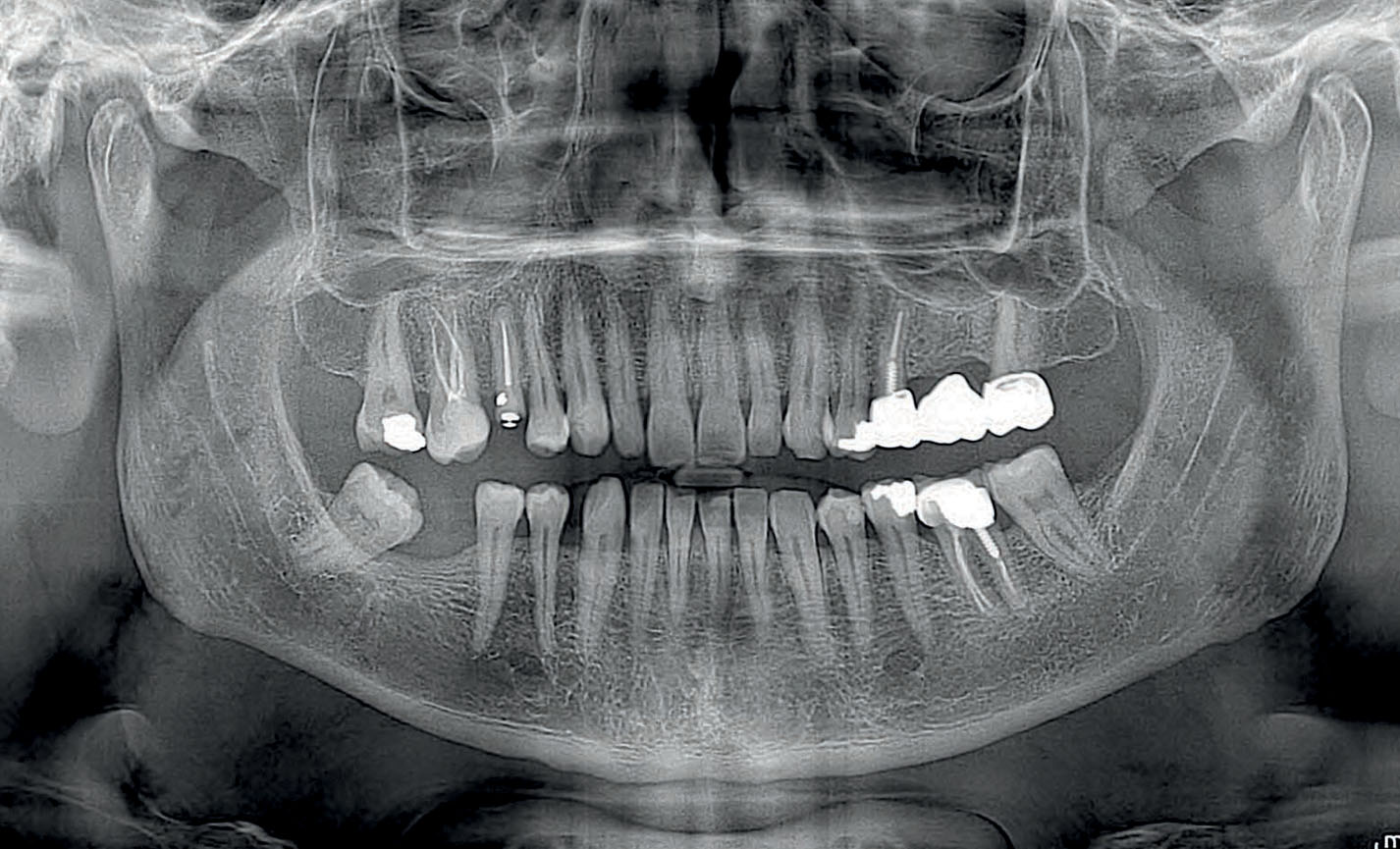
Dental panoramic radiographs
Orthogonal panoramic X-ray: minimises the overlapping of adjacent teeth and provides better periodontal analysis.
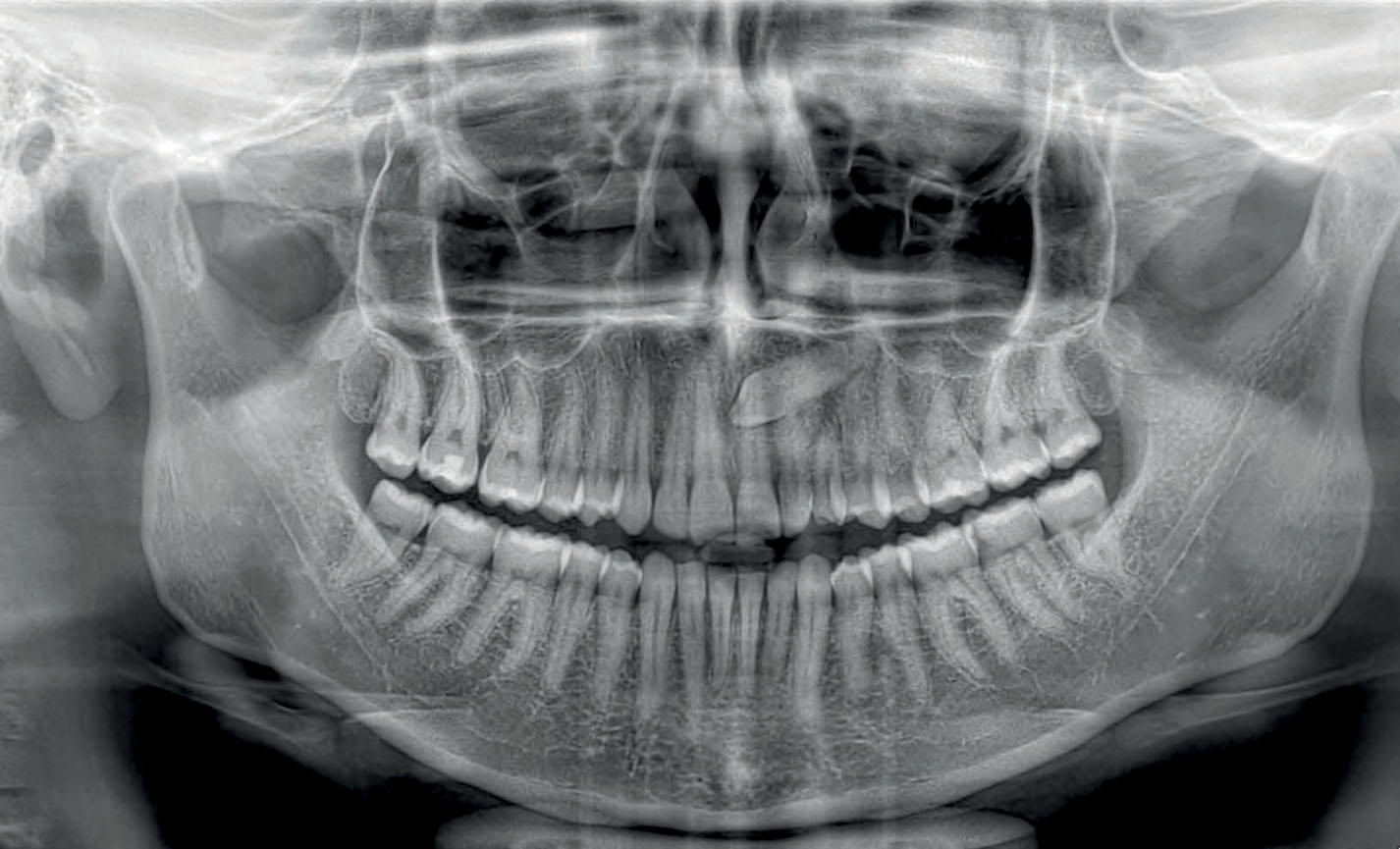
Dental panoramic radiographs
Fast panoramic X-ray: low dose and reduced scan time, perfect for primary investigations, follow-ups or uncooperative patients.

Dental panoramic radiographs
Child panoramic X-ray: limited exposure and optimised parameters for fast paediatric examinations.
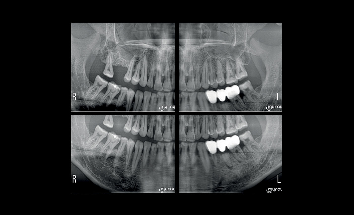
Dental panoramic radiographs
Complete dentition divided into quadrants: localised investigations with selectable segmentation to limit the irradiated dose.
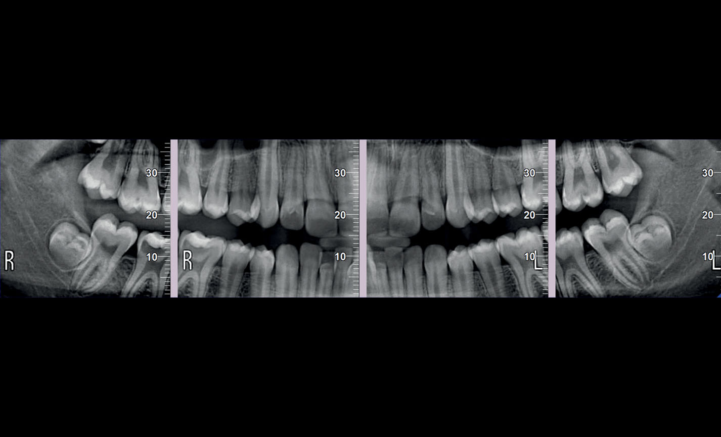
Dental panoramic radiographs
Bitewing projections limited to crowns: high resolution and low dose, a comfortable alternative to intraoral imaging, appreciated by patients with a strong gag reflex.
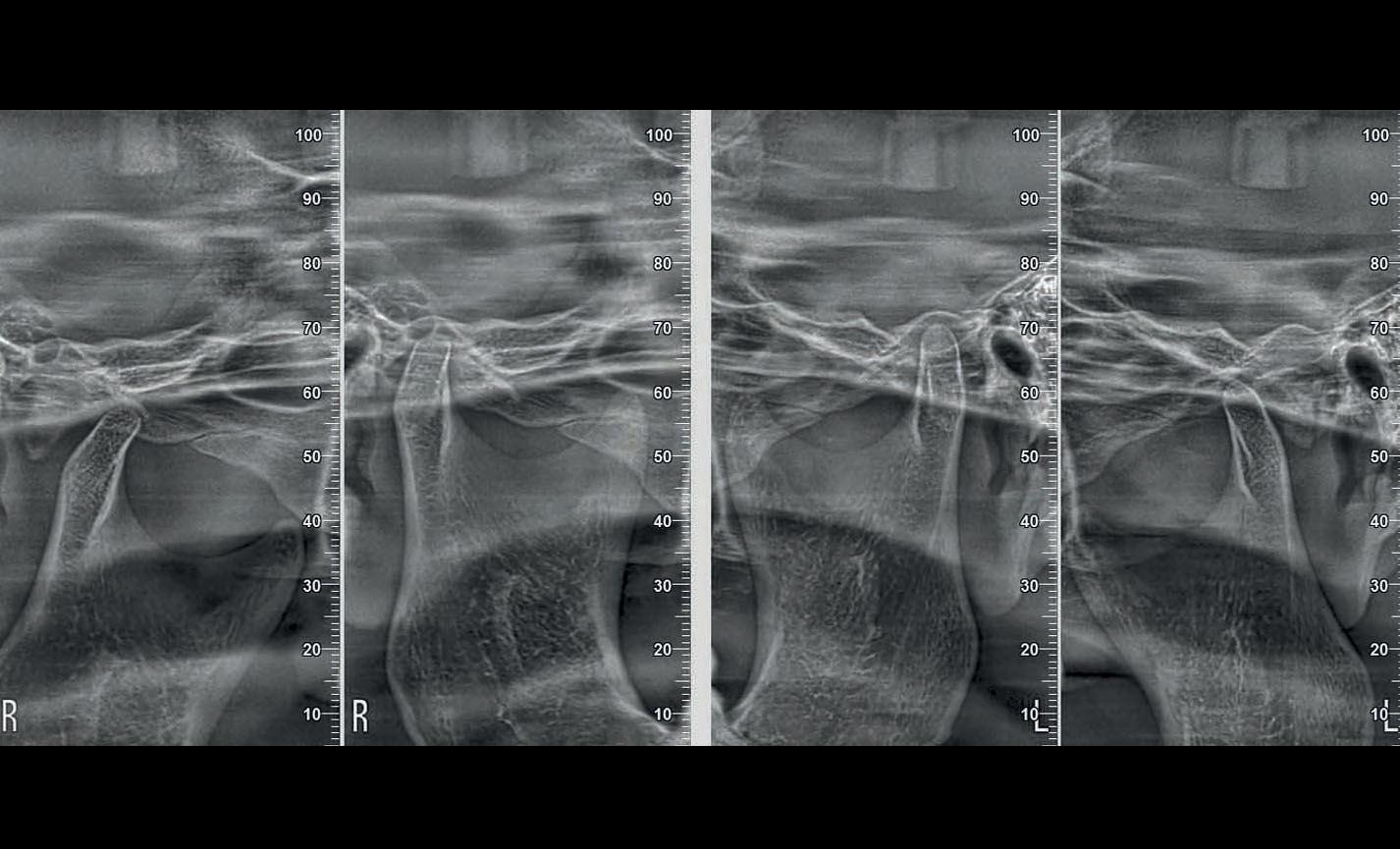
Stratigrafie extraorali
Articolazioni Temporo-Mandibolari: destra e sinistra, a bocca aperta o chiusa ed in proiezione latero-laterale e postero- anteriore con proiezione multi-angolare.
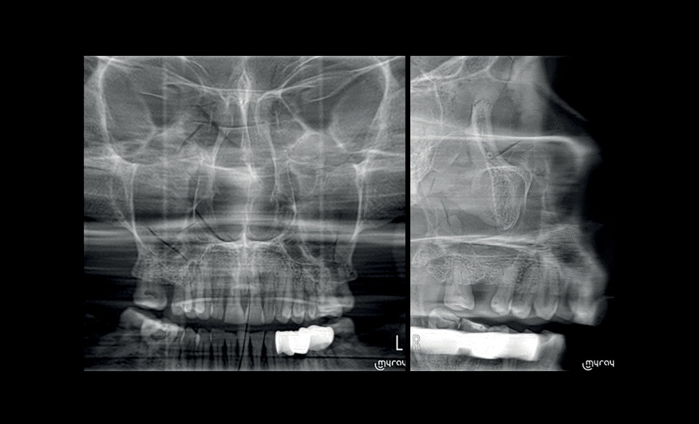
Stratigrafie extraorali
Seni Mascellari: in vista frontale, laterale destra e sinistra, con traiettoria ottimizzata.
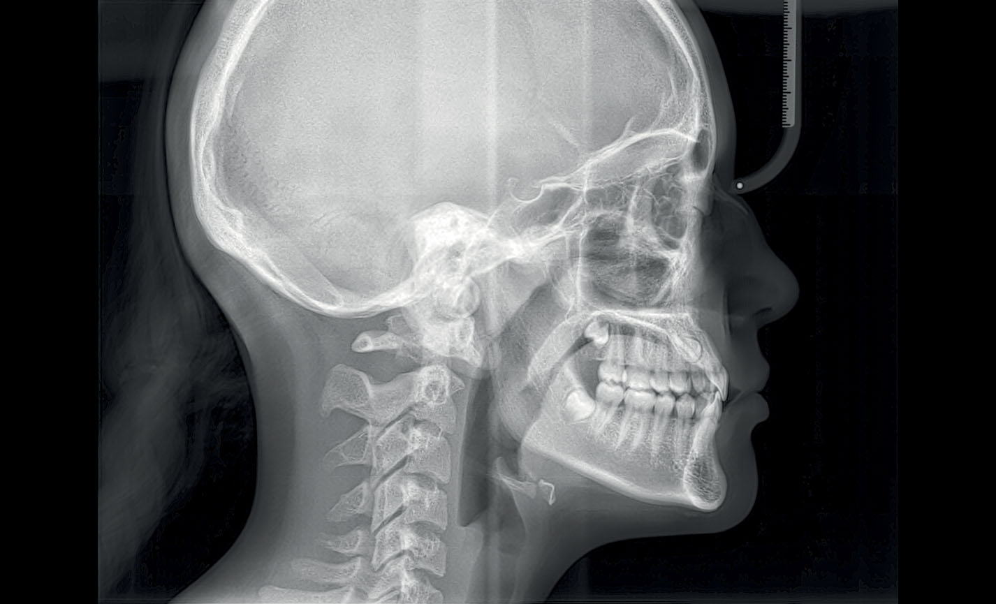
Teleradiografia
Latero-Laterale: con dettagli ossei e tessuti molli in evidenza, fondamentale per studi cefalometrici.
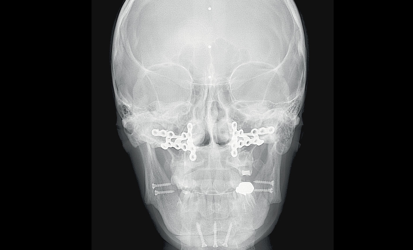
Teleradiografia
Antero-Posteriore: per indagare asimmetrie e malocclusioni al fine di un corretto trattamento.
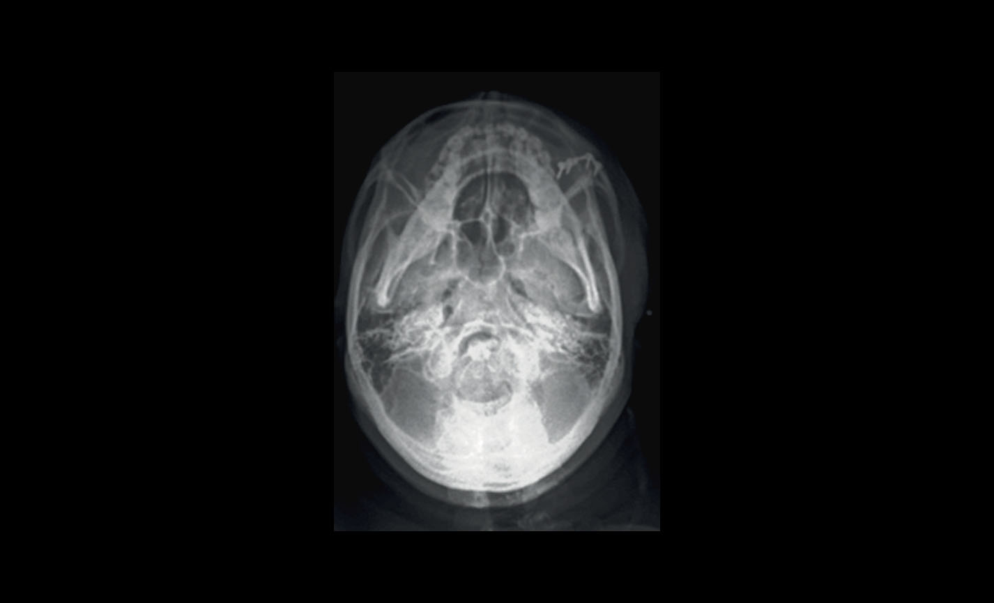
Teleradiografia
Sub-mento vertex: consente di analizzare fosse nasali, cellule etmoidali e seni sfenoidali.
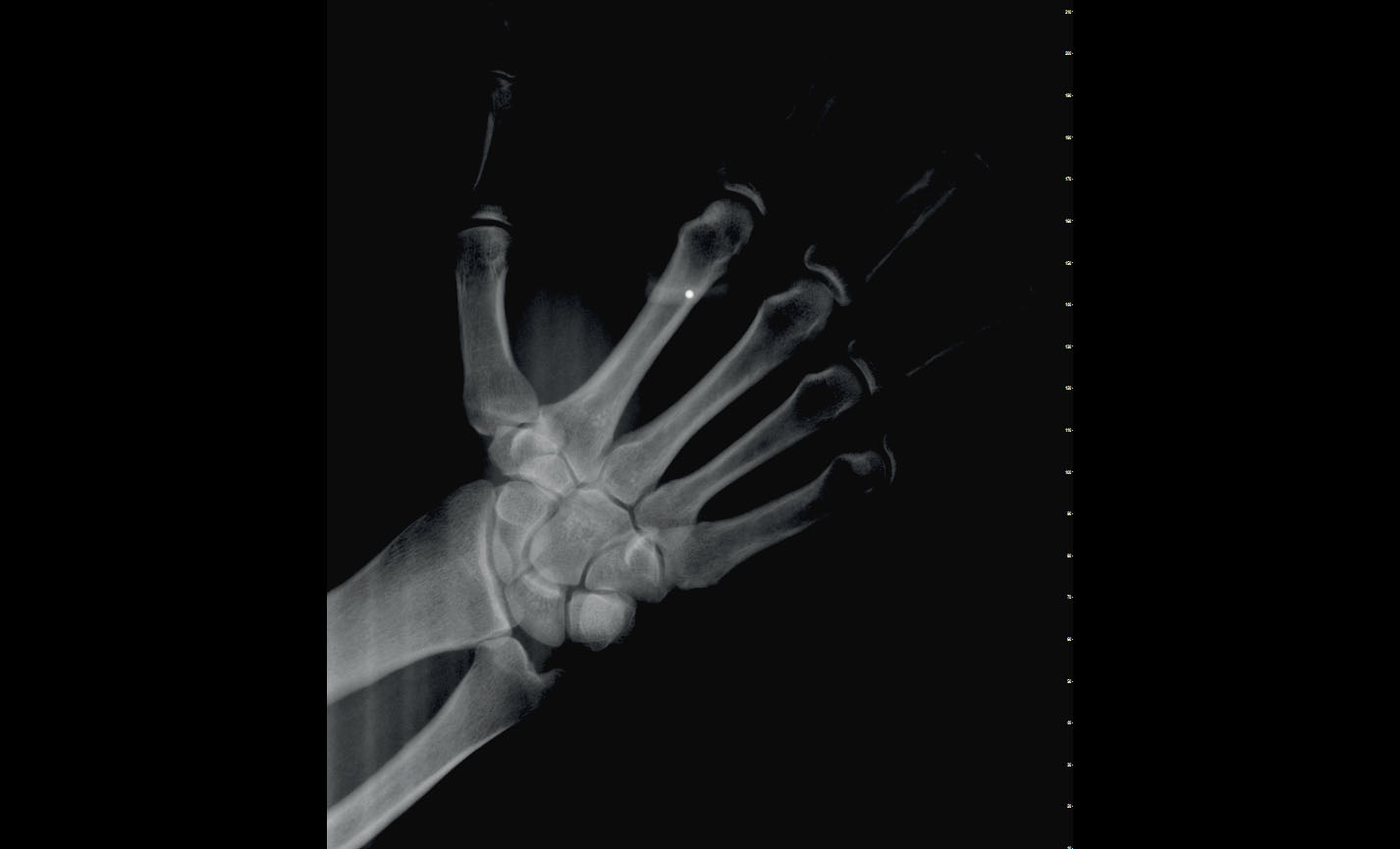
Teleradiografia
Carpo: per valutazione della crescita residua, possibile con supporto dedicato.
Orthodontic applications
FOVs with a 10 cm diameter are essential for the study of impacted third molars because, in an adult of medium build, the distance between the third molars on the left and right, including the respective roots, the alveolar process and the surrounding bone, is at least 9 cm. Reduced fields of view are useful when analysing impacted or supernumerary teeth in order to restrain the dose to the region of interest. For a correct treatment planning it is indeed crucial to determine the actual position (vestibular or palatal). This is only possible with a 3D analysis, even at a very low dose, with the QuickScan protocol. The complete 13 x 16 cm field of view allows for an accurate assessment of the upper airways, which is often useful to complete the investigation for an orthodontic treatment that does not neglect ENT problems.
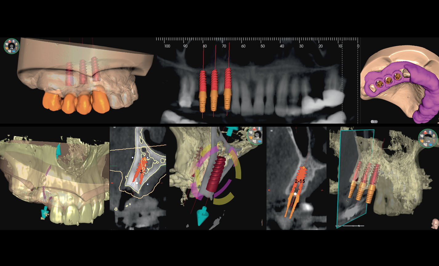
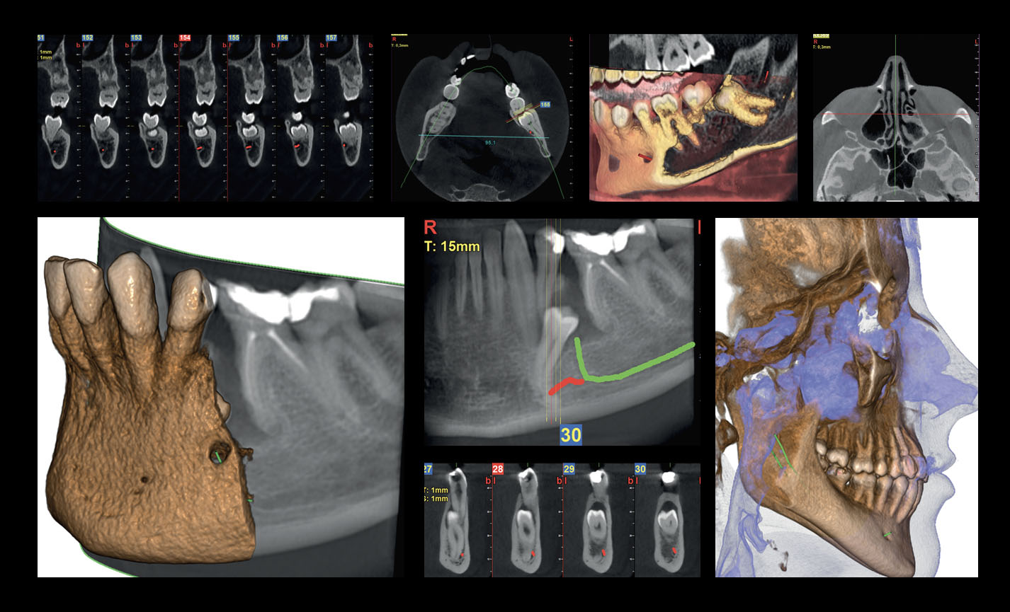
Advanced implant planning
Position the equipment directly on the 3D model, combine it with the STL data from intraoral scanners and define the final prosthetic project. With the advanced implant planning tools you will be able to operate safely thanks to accurate information on the amount of bone and the distance from the surrounding anatomical structures, such as the mandibular canal, defining a minimum safety distance.
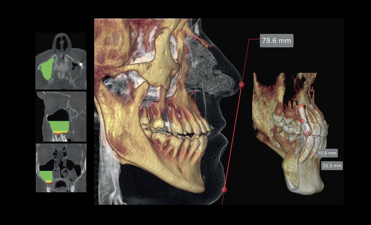
Volume analysis
The software feature for the assessment of the sinus floor lift volume allows for an early planning of the intervention and for a perfectly safe procedure. It is also possible to trace lines directly on the virtual model of the patient thereby assessing morphological relations on the 3D rendering.
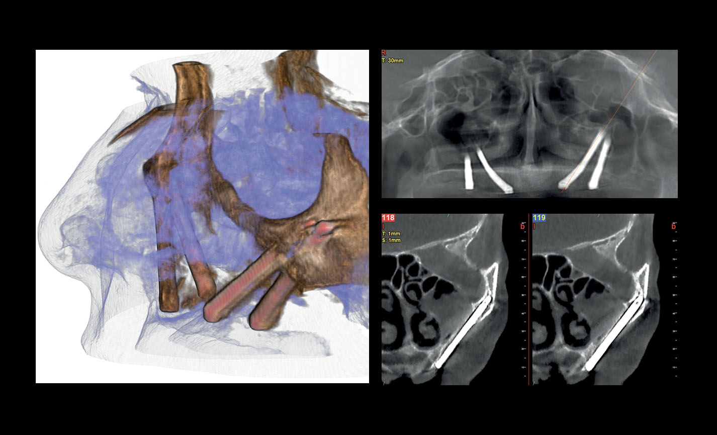
Assessment of zygomatic implants
Volumes with 13 x 8 cm or 13 x 10 cm FOV are the perfect tool for zygomatic implant planning as the 13cm diameter is the only one that makes it possible to include the entire zygomatic arch, without cuts.
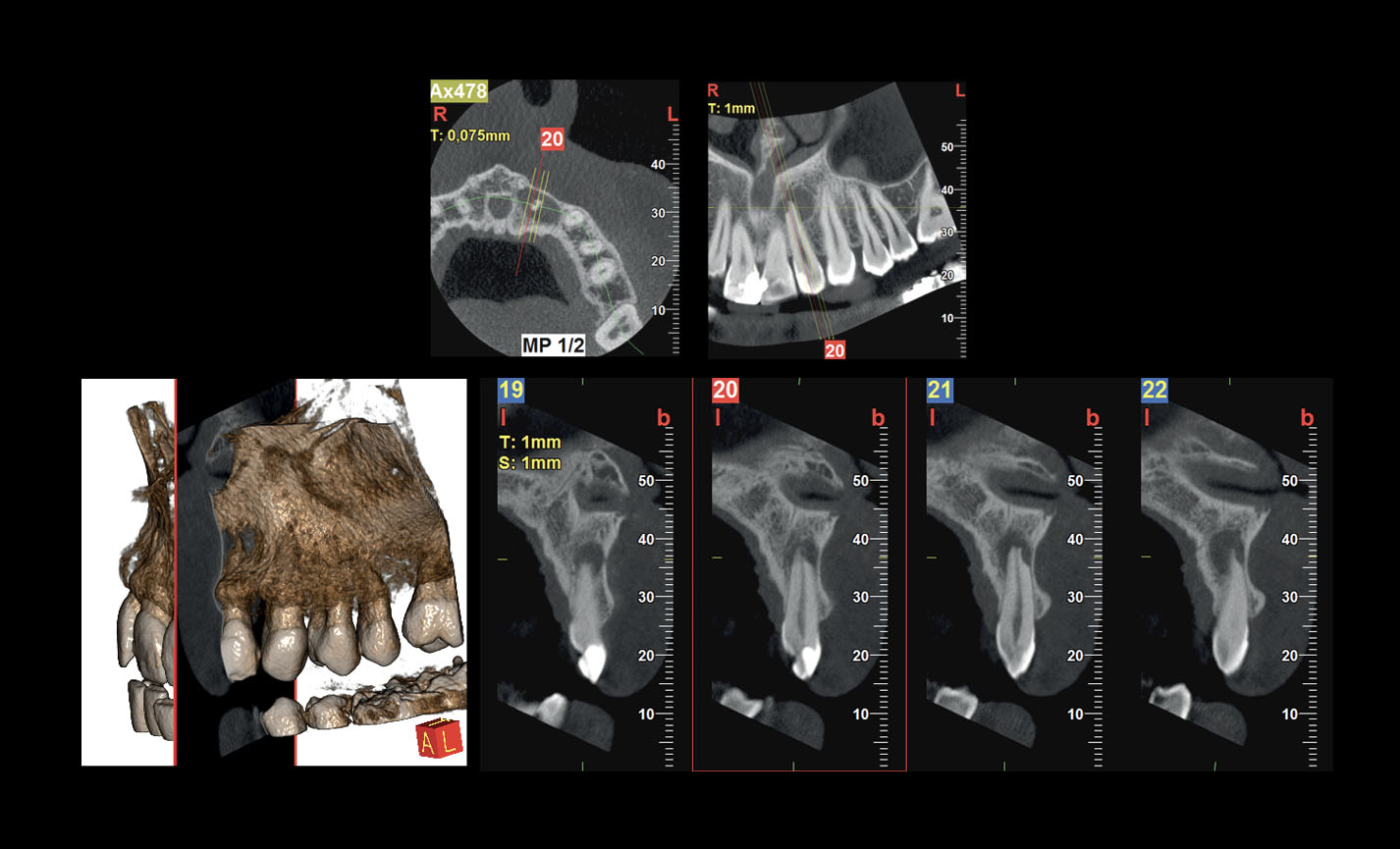
Endodontic examination
Treatment of the mandibular canal and identification of micro-fractures and root resorption: the exceptional 68 μm resolution, unique to Hyperion X9 pro, brings your diagnoses to a higher level.
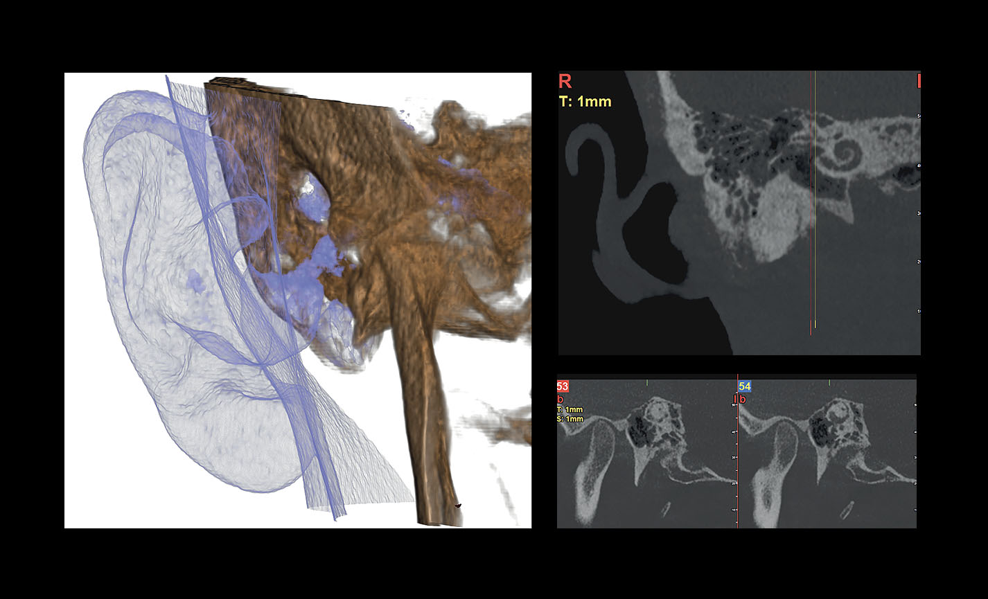
View of the inner and middle ear
The dedicated 7 x 6 cm FOV at 68 μm provides a clear and detailed view of all the structures in the inner and middle ear, such as the round window, the semicircular canal and the ossicular chain.
Перейти к контенту
В современном мире аппаратура для диагностики постоянно усовершенствуется. Новые технологии нуждаются в специальных программах обслуживания. Компания MyRay разработала программное обеспечение iRYS для рентгенологического оборудования собственного производства.
Эта уникальная программа, позволяющая моментально получать, сохранять и обрабатывать диагностические изображения.
На сегодняшний день это самое передовое компьютерное обеспечение. Его отличают:
- расширенные возможности;
- максимально удобный в эксплуатации интерфейс;
- точность и скорость;
- быстрый и качественный результат
iRYS незаменимый помощник при работе с медицинским оборудованием. У врачей появилась уникальная возможность мгновенно просматривать изображения в формате 3D, проводить цифалометрический анализ и панорамное сканирование.
Данное ПО совместимо с другими компьютерными программами. Удобство iRYS состоит и в том, что при помощи специальных графических редакторов можно корректировать изображения и проводить моделирование имплантатов. Врач получает максимально доступную информацию для восприятия.
Компания MyRay дорожит своей репутацией. Именно поэтому мы используем самые современные и передовые технологии в своих разработках.
- Manuals
- Brands
- Myray Manuals
- Medical Equipment
- hyperion X5
- Technical manual
-
Contents
-
Table of Contents
-
Bookmarks
Quick Links
Cod.
97070183
Rev. 00 05/2015
www.my-ray.com
Related Manuals for Myray hyperion X5
Summary of Contents for Myray hyperion X5
-
Page 1
Cod. 97070183 Rev. 00 05/2015 www.my-ray.com… -
Page 3
TECHNICAL MANUAL hyperion X5 Code Date 97071183 15.05… -
Page 5: Table Of Contents
TECHNICAL MANUAL — hyperion X5 PC CONFIGURATION ……………………… 5 1.1. SYSTEM REQUIREMENTS ……………………5 1.2. SETTING UP THE DEVICE ……………………6 1.2.1. PRELIMINARY OPERATIONS ………………….6 1.2.2. OPERATING SYSTEM SETTINGS ………………..6 …
-
Page 6
… -
Page 7: Pc Configuration
1. PC CONFIGURATION 1.1. SYSTEM REQUIREMENTS hyperion X5 needs two ethernet connections, one for generic communication purposes (this supports DHCP and can be set up through the local network) and a second dedicate connection, which must set up as direct point-to-point between the unit and the INTEL PRO 1000 network card on the PC.
-
Page 8: Setting Up The Device
PC and install the software correctly. The 2 network adapters on the acquisistion server are needed for communication with the hyperion X5. One of these network adapters is used for a direct connection with the image detector on the X5.
-
Page 9
TECHNICAL MANUAL — hyperion X5 Select the lowest notification level “Never Notify”. RESTART THE PC. From the Control Panel select “Power Options”. PC CONFIGURATION… -
Page 10
TECHNICAL MANUAL — hyperion X5 On the “Balanced”profile select “Change plan settings”. Set“Turn OFF display”and“Put the computer to sleep”to“Never”. Select “Change advanced power settings”. Set“Hard disk Turn OFF hard disk after 0”. Also deactivate any screensaver. To do this right click on the mouse on any icon-free desktop or window area and select “Personalize”… -
Page 11: Disabling Windows Firewall
TECHNICAL MANUAL — hyperion X5 Also deactivate any screensaver. To do this right click on the mouse on any icon-free desktop or window area and select “Personalize” from the menu. 1.2.3. DISABLING WINDOWS FIREWALL From the Control Panel select “Administrative Tools”…
-
Page 12: Intel Pro 1000″ Network Card Installation
TECHNICAL MANUAL — hyperion X5 Scroll down the service list, right click on the “Windows firewall” service and double click. Go to the “Startup type” drop-down menu and select “Disabled”. Then press the “Stop” key to stop the service currently being executed.
-
Page 13
TECHNICAL MANUAL — hyperion X5 Expand the “Newtork Adapter” group, right click on the “Intel pro 1000”, and select “Properties”. Select the “Advanced” tab, highlight the “Jumbo Packet”, and set it to “9014 byte PC CONFIGURATION… -
Page 14: Acquisition Server» Software Installation
TECHNICAL MANUAL — hyperion X5 From the “Advanced” tab set the “Receive Buffers” parameter to 2048 WARNING: the “Receive Buffers” parameter migh not show on this window. If not visible, please search for the “Performance options” parameter, click on “Properties” and set the “Receive bufffers” value from there.
-
Page 15
TECHNICAL MANUAL — hyperion X5 Select “I accept” , then click “Next” Click on “Install” Wait PC CONFIGURATION… -
Page 16
TECHNICAL MANUAL — hyperion X5 Installed software will be checked, any missing system component will be installed at this stage. The Pleora driver for the Intel Pro 1000 network adapter will be installed automatically, click “Next” Accept and click “Next”… -
Page 17
TECHNICAL MANUAL — hyperion X5 Click on “Install” Wait for the driver installation to finish. If the following window is displayed, select “Always Trust” and click “Install” PC CONFIGURATION… -
Page 18
TECHNICAL MANUAL — hyperion X5 Click “Finish” at the end of the installation. Restart the PC The “Acquisition server” software will start up automatically and will be accessible from the system tray. PC CONFIGURATION… -
Page 19: Connection And Configuration
(DHCP) and the connection is managed automatically. It could be necessary to set up a static IP address for the network adapter used for the PC to hyperion X5 system communication. If this network adapter is directly connected to the unit, the IP address for the PC should be set to one in the same subnet as the hyperion X5’s default (e.g.192.168.1.150)
-
Page 20
If the unit is connected to a LAN with DHCPC (as in the following diagram) then the noetwork adapter should be set to “Obtain IP address automatically”. The DHCP server will assign correct IP addresses to both the hyperion X5 and the acquisistion server. -
Page 21
TECHNICAL MANUAL — hyperion X5 Once the IP addresses have been configured correctly you can start setting up the Acquisistion Server software. Click on the Acquisition Server icon in the system tray, the main window will be magnified in “User”… -
Page 22
TECHNICAL MANUAL — hyperion X5 On program restard you’ll be prompted to select the application mode. Select “Service mode”. enter the password “cefla”. Restart the “Acquisition Server” software, now in “Service mode”. Click on “Settings” and select “Find Device”. PC CONFIGURATION… -
Page 23
TECHNICAL MANUAL — hyperion X5 hyperion X5 X5 will be found, select the line and continue. Select “Connect Device” and activate the “Auto connect device” option. Click on “Close”. In a few seconds the connection to the hyperion X5 will be estabilished. -
Page 24: Irys Installation And Configuration
1.3.2. IRYS INSTALLATION AND CONFIGURATION The imaging software used with Hyperion X5 is “iRys” (version 5.5 or later), installed in “Station” version. It is not strictly necessary to install iRys on the Acquisistion Server PC, iRys can be installed on any PC in the network that could communicate with the Acquisition Server PC.
-
Page 25
TECHNICAL MANUAL — hyperion X5 Load the Irys installation CD and follow the instructions on the screen. Select “IRYS Station” installation: Continue by confirming the installation path: PC CONFIGURATION… -
Page 26
TECHNICAL MANUAL — hyperion X5 Click “Install”: Click ok to confirm. To connect the hyperion X5 to iRYS, start iRYS and press “CTRL + ALT + SHIFT + FINE” simultaneously to access the service level of the program, confirmed by the message in the bottom right-hand corner: Now press “ALT + F10”… -
Page 27
Configure the remote connection as shown in the image here below. Click “Save” and then “Exit”. The .hyperion X5 connection status icon will appear in the upper right corner of iRys’ interface. Click on the icon and select “Virtual keyboard”:… -
Page 28
TECHNICAL MANUAL — hyperion X5 On first startup the console will prompt with this message: In order to authorize the virtual keyboard to connect to the unit, you need to enter the “Acquisition server” software and select “Clients allowed”: The clients list will appear, select the appropriate one and close the window. -
Page 29
TECHNICAL MANUAL — hyperion X5 Now the .hyperion X5 virtual keyboard will connect correctly: PC CONFIGURATION… -
Page 30: Calibration
TECHNICAL MANUAL — hyperion X5 2. CALIBRATION 2.1. PRELIMINARY OPERATIONS Open the acquisition server software, click on “Settings”, then on “Change Mode” and confirm when prompted. Select “Service mode” and enter the password “cefla”. CALIBRATION…
-
Page 31: Device Configuration
TECHNICAL MANUAL — hyperion X5 Open the Acquisistion server software and click on “Calibration”. 2.2. DEVICE CONFIGURATION …
-
Page 32: Xray Alignment
TECHNICAL MANUAL — hyperion X5 Enter the serial number of the column in the textbox and presso “OK” 2.3. XRAY ALIGNMENT A correct alignment should result in an image like the example shown on the left side of the window (dark rectangle with white background);…
-
Page 33
TECHNICAL MANUAL — hyperion X5 Make sure to remove every object from the scan area (bite support, chin support, aluminum filter, calibration phantom) Press the exposure button when required, hold until asked to release. CALIBRATION… -
Page 34
TECHNICAL MANUAL — hyperion X5 If the resulting image is not centered (like the one in the following picture), the collimator needs to be manually moved. Remove the screws shown below to in order to remove the front cover of the generator. -
Page 35
TECHNICAL MANUAL — hyperion X5 Select the “not centered” option in the calibration tool, then presso “OK” to start a new acquisition in order to verify the change made. Repeat the procedure until the x-ray beam is correctly aligned. Centering the collimator vertically Slightly loosen the “A”… -
Page 36: Verifying The Sensor Calibration
TECHNICAL MANUAL — hyperion X5 2.4. VERIFYING THE SENSOR CALIBRATION Click on “Start procedure”, make sure to have positioned the aluminum filter on the front cover of the generator and to have removed every object from the scan area (bite support, chin support,…
-
Page 37: Verifying The Mechanical Centering
TECHNICAL MANUAL — hyperion X5 2.5. VERIFYING THE MECHANICAL CENTERING Remove the bite support, chin support and aluminum filter. Mount the calibration phantom inserting the supporting pins into the holes previously used for the chin support. CALIBRATION…
-
Page 38
TECHNICAL MANUAL — hyperion X5 Click on “Acquire”. Press the exposure button when required, hold until asked to release. The calibration software will download a complete panoramic image and will show it on screen. You’ll need to verify that the focal area is centered. Use the dots as reference. -
Page 39: Test Laser
TECHNICAL MANUAL — hyperion X5 2.6. TEST LASER Mount the laser guide tool on top of the calibration phantom (as shown below) and press “Start test”. CALIBRATION…
-
Page 40
TECHNICAL MANUAL — hyperion X5 The unit will rotate into position for the laser test. Check the alignment of the beams (sagittal, canine, and frankfurt plane) with the reference marks on the test object. CALIBRATION… -
Page 41
TECHNICAL MANUAL — hyperion X5 If one or more of the laser beams is not aligned, use pliers to loosen the spring around the projector support and align the beam manually. The frankfurt plane and canine lasers are under the generator cover. -
Page 42: Calibration Data Backup
TECHNICAL MANUAL — hyperion X5 2.7. CALIBRATION DATA BACKUP Click on “Export”, select the destination folder and confirm. CALIBRATION…
-
Page 43: Control Boards Description
TECHNICAL MANUAL — hyperion X5 3. CONTROL BOARDS DESCRIPTION 3.1. UNIT BLOCK DIAGRAM CONTROL BOARDS DESCRIPTION…
-
Page 44: Power Board 97661407
TECHNICAL MANUAL — hyperion X5 3.2. POWER BOARD 97661407 CONTROL BOARDS DESCRIPTION…
-
Page 45
TECHNICAL MANUAL — hyperion X5 CONTROL BOARDS DESCRIPTION… -
Page 46: Connectors List
TECHNICAL MANUAL — hyperion X5 3.2.1. CONNECTORS LIST CONNECTOR DESCRIPTION Mains power supply Power switch live wire Power switch neutral wire External emergency button — optional Door interlock — optional X-ray button External signal lamps – Optional- Wires 1,2 ready — Wires 3,4 x-ray emission Power supply for “logic”…
-
Page 47
TECHNICAL MANUAL — hyperion X5 LED ID COLOR NAME ON BOARD DESCRIPTION On when 390V are present on power amplifier. YELLOW Off when in stand-by or in case of issues with the power amplifier. DL10 GREEN -5VA Analog -5.3V present, normally on… -
Page 48: Logic Board 97661408
TECHNICAL MANUAL — hyperion X5 3.3. LOGIC BOARD 97661408 CONTROL BOARDS DESCRIPTION…
-
Page 49
TECHNICAL MANUAL — hyperion X5 CONTROL BOARDS DESCRIPTION… -
Page 50: Connectors List
TECHNICAL MANUAL — hyperion X5 3.3.1. CONNECTORS LIST CONNECTOR DESCRIPTION Ethernet connection to PC Powe supply and sync signal for sensor interface card. Not used Power supply input from powe board 24V power supply toward engraved logo light K26 K23…
-
Page 51
TECHNICAL MANUAL — hyperion X5 LED ID COLOR NAME ON BOARD DESCRIPTION DL15 GREEN Acknowledged signal from LOGIC board, always on. DL16 GREEN XRAY X-ray emission signal from Power board. Normally off, on during emission. DL17 GREEN SD_ON Not used. -
Page 52: Sensor Interface Board 97661485
TECHNICAL MANUAL — hyperion X5 3.4. SENSOR INTERFACE BOARD 97661485 CONTROL BOARDS DESCRIPTION…
-
Page 53
TECHNICAL MANUAL — hyperion X5 CONTROL BOARDS DESCRIPTION… -
Page 54: Connectors List
TECHNICAL MANUAL — hyperion X5 3.4.1. CONNECTORS LIST CONNECTOR DESCRIPTION Sync signal and power supply for sensor, from LOGIC board. Sensor power supply, 2x 5V DC Sensor synchronization 3.4.2. LEDS LIST LED ID DESCRIPTION DL1 (VIN) 48V from LOGIC board…
Современные томографы и рентген аппараты создаются на базе уникальных технологий. Сложные системы всегда требуют специального программного обеспечения. Компания MyRay специально для своего рентген оборудования создала ПО iRYS.
Эта уникальная система позволяет за считанные минуты получать, просматривать и корректировать готовое изображение.
Программное обеспечение iRYS обладает прекрасными для работы качествами:
- большие возможности
- максимальный результат
- максимально эргономичный интерфейс
- точность
- скорость
iRYS — это наиболее современное, а может даже совершенное ПО для медицинского оборудования.
С его помощью врач может удивительно быстро просмотреть готовые снимки всех проекций:
- 3D-снимки
- цефалометрия
- панорамное сканирование
Программное обеспечение iRYS удобно и тем что совместимо с другими ПО. Так же с его помощью можно легко моделировать имплантаты, корректировать изображения с помощью профессиональных графических редакторов.
Благодаря iRYS врач получает максимум информации в понятной, доступном для восприятия специалиста виде.
Компания MyRay дорожит своими покупателями. Поэтому все оборудование производителя максимально технологично.
7. ПРОСМОТР И СОХРАНЕНИЕ ИЗОБРАЖЕНИЙ
Для просмотра и сохранения снимков необходимо иметь ПК.
Рентгеновская установка снабжена программой iRYS для просмотра и сохранения снимков (смотрите
руководство для пользователя iRYS).
ПО iRYS необходимо для получения томографических снимков, так как оно использует технологию по
реконструкции объемных изображений (только для варианта исполнения 3D).
При необходимости передачи рентгеновского снимка пациенту или другому оператору iRYS автоматически
направит вас на создание DVD, включающего копию iRYS для просмотра изображений (iRYS Viewer), не
ограниченную для свободного распространения.
В ином случае вы сможете экспортировать только рентгеновские снимки в стандартном формате (DICOM 3.0),
чтобы их можно было просматривать с помощью программ других разработчиков.
48
ИНСТРУКЦИИ ПО ПРИМЕНЕНИЮ
RU
Dental panoramic radiographs
Orthogonal panoramic X-ray: minimises the overlapping of adjacent teeth and provides better periodontal analysis.
Dental panoramic radiographs
Fast panoramic X-ray: low dose and reduced scan time, perfect for primary investigations, follow-ups or uncooperative patients.
Dental panoramic radiographs
Child panoramic X-ray: limited exposure and optimised parameters for fast paediatric examinations.
Dental panoramic radiographs
Complete dentition divided into quadrants: localised investigations with selectable segmentation to limit the irradiated dose.
Dental panoramic radiographs
Bitewing projections limited to crowns: high resolution and low dose, a comfortable alternative to intraoral imaging, appreciated by patients with a strong gag reflex.
Stratigrafie extraorali
Articolazioni Temporo-Mandibolari: destra e sinistra, a bocca aperta o chiusa ed in proiezione latero-laterale e postero- anteriore con proiezione multi-angolare.
Stratigrafie extraorali
Seni Mascellari: in vista frontale, laterale destra e sinistra, con traiettoria ottimizzata.
Teleradiografia
Latero-Laterale: con dettagli ossei e tessuti molli in evidenza, fondamentale per studi cefalometrici.
Teleradiografia
Antero-Posteriore: per indagare asimmetrie e malocclusioni al fine di un corretto trattamento.
Teleradiografia
Sub-mento vertex: consente di analizzare fosse nasali, cellule etmoidali e seni sfenoidali.
Teleradiografia
Carpo: per valutazione della crescita residua, possibile con supporto dedicato.
Orthodontic applications
FOVs with a 10 cm diameter are essential for the study of impacted third molars because, in an adult of medium build, the distance between the third molars on the left and right, including the respective roots, the alveolar process and the surrounding bone, is at least 9 cm. Reduced fields of view are useful when analysing impacted or supernumerary teeth in order to restrain the dose to the region of interest. For a correct treatment planning it is indeed crucial to determine the actual position (vestibular or palatal). This is only possible with a 3D analysis, even at a very low dose, with the QuickScan protocol. The complete 13 x 16 cm field of view allows for an accurate assessment of the upper airways, which is often useful to complete the investigation for an orthodontic treatment that does not neglect ENT problems.
Advanced implant planning
Position the equipment directly on the 3D model, combine it with the STL data from intraoral scanners and define the final prosthetic project. With the advanced implant planning tools you will be able to operate safely thanks to accurate information on the amount of bone and the distance from the surrounding anatomical structures, such as the mandibular canal, defining a minimum safety distance.
Volume analysis
The software feature for the assessment of the sinus floor lift volume allows for an early planning of the intervention and for a perfectly safe procedure. It is also possible to trace lines directly on the virtual model of the patient thereby assessing morphological relations on the 3D rendering.
Assessment of zygomatic implants
Volumes with 13 x 8 cm or 13 x 10 cm FOV are the perfect tool for zygomatic implant planning as the 13cm diameter is the only one that makes it possible to include the entire zygomatic arch, without cuts.
Endodontic examination
Treatment of the mandibular canal and identification of micro-fractures and root resorption: the exceptional 68 μm resolution, unique to Hyperion X9 pro, brings your diagnoses to a higher level.
View of the inner and middle ear
The dedicated 7 x 6 cm FOV at 68 μm provides a clear and detailed view of all the structures in the inner and middle ear, such as the round window, the semicircular canal and the ossicular chain.
7. ПРОСМОТР И СОХРАНЕНИЕ ИЗОБРАЖЕНИЙ
Для просмотра и сохранения снимков необходимо иметь ПК.
Рентгеновская установка снабжена программой iRYS для просмотра и сохранения снимков (смотрите
руководство для пользователя iRYS).
ПО iRYS необходимо для получения томографических снимков, так как оно использует технологию по
реконструкции объемных изображений (только для варианта исполнения 3D).
При необходимости передачи рентгеновского снимка пациенту или другому оператору iRYS автоматически
направит вас на создание DVD, включающего копию iRYS для просмотра изображений (iRYS Viewer), не
ограниченную для свободного распространения.
В ином случае вы сможете экспортировать только рентгеновские снимки в стандартном формате (DICOM 3.0),
чтобы их можно было просматривать с помощью программ других разработчиков.
48
ИНСТРУКЦИИ ПО ПРИМЕНЕНИЮ
RU