-
Contents
-
Table of Contents
-
Bookmarks
Quick Links
Related Manuals for JOYEE ZJ9610

Summary of Contents for JOYEE ZJ9610
-
Page 5
Index Contexts Contexts Chapter — Page Chapter — Page 1 — 1 1 — 1 Safety Safety 1 — 1 1 — 1 1.01 1.01 Safety symbols Safety symbols 1 — 1 1 — 1 1.02 1.02 Important points for the user Important points for the user 1 — 2 1 — 2… -
Page 6
Index Index 7.03 7.03 Winding the bobbin thread; adjusting the primary thread tension Winding the bobbin thread; adjusting the primary thread tension 7 — 3 7 — 3 7.04 7.04 Removing/Inserting the bobbin case Removing/Inserting the bobbin case 7 — 4 7 — 4 7 — 4 7 — 4… -
Page 7
Index 9 — 23 9 — 23 9.03.19 9.03.19 Roller presser Roller presser 9 — 24 9 — 24 9.03.20 9.03.20 Stitch length on stitch length scale Stitch length on stitch length scale 9 — 25 9 — 25 9.03.21 9.03.21 Synchronization of roller presser and feed wheel Synchronization of roller presser and feed wheel… -
Page 8
Safety Safety Safety Safety 1.01 1.01 Safety symbols Safety symbols ! ! Danger! Danger! ! 。 。 Points to be observed Points to be observed ! ! Danger of injury for operating and Danger of injury for operating and specialist personnel specialist personnel !… -
Page 9
Safety Safety 1.03 1.03 Danger Danger , , , , 、 、 。 。 ! A working area of 1 meter is to be kept free both in front of and behind A working area of 1 meter is to be kept free both in front of and behind the machine in operation so that the machine is always easily the machine in operation so that the machine is always easily accessible. -
Page 10
Safety Safety ! ! ! ! Switch the machine off before tilting it backwards! Switch the machine off before tilting it backwards! Danger of injury if the machine is started accidentally! Danger of injury if the machine is started accidentally! !… -
Page 11
Proper use Proper use Proper use Proper use 9625 9625 Is a single needle, high-speed post bed sewing Is a single needle, high-speed post bed sewing machine (post to the left of the needle) with driven machine (post to the left of the needle) with driven feed wheel and roller presser and synchronized needle. -
Page 12
Specifications Specifications Specifications Specifications 3.01 3.01 9630, 9625, 9620 , 9610 9630, 9625, 9620 , 9610 Stitch type Stitch type 301 ( 301 ( /lockstitch) /lockstitch) Clearacne under roller presser Clearacne under roller presser 7 mm 7 mm Clearance width Clearance width 245 mm 245 mm… -
Page 13
Specifications Specifications 3.02 3.02 Needles and threads Needles and threads ▲ (Nm) ▲ (Nm) 9630 9630 9620 9620 9625 9625 9610 9610 ▲ ▲ 1/100mm 1/100mm 60/3 40/3 134-35 15/3 134-35 Thread thickness Thread thickness ▲Needle ▲Needle 9630 9630 9625 9625 9620 9620… -
Page 14
Explanation of symbols Explanation of symbols Explanation of symbols Explanation of symbols , , 。 。 : : In this Instruction Manual, work to be carried out or important information In this Instruction Manual, work to be carried out or important information is accentuated by symbols which have the following meanings: is accentuated by symbols which have the following meanings: ,… -
Page 15
Controls Controls Controls Controls 5.01 5.01 ( ( -D3、9630 -D3、9630 ) ) Keys on the machine head (only for machines with-D3 9630) Keys on the machine head (only for machines with-D3 9630) 、 、 ● ● , , , , 。… -
Page 16
Controls Controls 5.03 5.03 Pedal Pedal Neutral position Neutral position Sewing Sewing ( ( 、 、 9630 9630 …. ) ) Raiser roller presser(on machines with- Raiser roller presser(on machines with- 、 、 9630 9630 -D.. -D.. ) ) Trim sewing threads (on machines with-D..) Trim sewing threads (on machines with-D..) 5.04… -
Page 17
Controls Controls 5.06 5.06 Key for setting stitch length Key for setting stitch length ● ● 7.08 “ 7.08 “ ” ” ( ( )。 )。 ● ● The stitch length is set by pressing key The stitch length is set by pressing key and turning the balance wheel (see and turning the balance wheel (see Chapter 7.08 Setting the stitch length… -
Page 18
Installation and commissioning Installation and commissioning Installation and comminssioning Installation and comminssioning The machine must only be installed and commissioned by qualified The machine must only be installed and commissioned by qualified personnel! personnel! All relevant safety regulations must be strictly adhered to! All relevant safety regulations must be strictly adhered to! If the machine is delivered without a table, be sure to use a stand and If the machine is delivered without a table, be sure to use a stand and… -
Page 19
Installation and commissioning Installation and commissioning 6.02 6.02 Fitting the reel stand Fitting the reel stand ● ● 。 。 ● ● 。 。 ● Fit the reel stand as shown in Fig ● Fit the reel stand as shown in Fig ●… -
Page 20
Installation and commissioning Installation and commissioning 6.02.03 6.02.03 Fitting the machine cover Fitting the machine cover ● ● , , , , 。 。 ● ● 。 。 6.02.04 6.02.04 Mounting the flange motor to the bearing plate Mounting the flange motor to the bearing plate ●… -
Page 21
Installation and commissioning Installation and commissioning 6.02.05 6.02.05 Mounting the flange motor to the machine Mounting the flange motor to the machine Lagerplatte 1 des motors 2 am Lagerplatte 1 des motors 2 am maschin engehause mit den maschin engehause mit den schrauben 3 anschrauben (schrauben schrauben 3 anschrauben (schrauben 3 nur leicht anziehen). -
Page 22
Installation and commissioning Installation and commissioning 6.02.07 6.02.07 Mounting the belt guard of the flange motor Mounting the belt guard of the flange motor ● ● ● Riemenschutz 1mit den schr- ● Riemenschutz 1mit den schr- auben 2 und 3 anschrauben. auben 2 und 3 anschrauben. -
Page 23
Installation and commissioning Installation and commissioning 6.03 6.03 Commissioning Commissioning ● ● 。 。 ● ● , , ( ( 11 “ 11 “ ”)。 ”)。 ● ● 。 。 , , 。 。 , , 。 。 ● ● Check the machine, particularly the electrical wiring for any damage. -
Page 24
Installation and commissioning Installation and commissioning 6.05 6.05 Tilted work base Tilted work base 6.06 6.06 Mounting the table top Mounting the table top… -
Page 25
Preparation Preparation Preparation Preparation 。 。 ! ! ! All instructions and regulations in this Instrution Manual must be All instructions and regulations in this Instrution Manual must be observed . observed . Special attention must be paid to all safety regulations! Special attention must be paid to all safety regulations! 。… -
Page 26
Preparation Preparation 7.02 7.02 9620 9620 Inserting the needle on model 9620 Inserting the needle on model 9620 ! ! ! ! Switch the machine off! Danger of injury if the machine is started accidentally! Switch the machine off! Danger of injury if the machine is started accidentally! 134-35 134-35 。… -
Page 27
Preparation Preparation 7.03 7.03 ; ; Winding the bobbin thread; adjusting the primary thread tension ● ● 。 。 9-03 9-03 ● ● , , 。 。 ● ● , , 。 。 ● ● Place an empty bobbin Place an empty bobbin into bobbin winder spindle . -
Page 29
Preparation Preparation 7.06 7.06 9630 9625 9610 9630 9625 9610 、 、 Threading the needle thread and regulating its tension on Threading the needle thread and regulating its tension on model 9630 9625 and 9610. model 9630 9625 and 9610. 、… -
Page 30
Preparation Preparation 7.07 7.07 9620 9620 Threading the needle thread and regulating its tension on Threading the needle thread and regulating its tension on model 9620 model 9620 Switch the machine off! Switch the machine off! Danger of injury if the machine is started accidentally! Danger of injury if the machine is started accidentally! Tilt up the eye guard . -
Page 31
Preparation Preparation 7.08 7.08 Setting the stitch length Setting the stitch length ● ● 。 。 ● ● , , 。 。 ● ● Press key Press key and at the same time turn the balance wheel until the and at the same time turn the balance wheel until the stitch setter clicks into position. -
Page 32
Care and Maintenance Care and Maintenance Care and Maintenance Care and Maintenance ………………………………………… ………………………………………… , , , , ( ( ) ………………………………… ) ………………………………… , , ……………………………………………………… ……………………………………………………… , , …………………………………………………………… …………………………………………………………… ……………………………………………… ……………………………………………… , , ……………………………………… ……………………………………… Clean Clean ……………………………… -
Page 33
Care and Maintenance Care and Maintenance 8.02 8.02 Clean the air filter of the air-filter/lubricator Clean the air filter of the air-filter/lubricator Switch the machine off! Switch the machine off! Disconnect the air hose at the air-filter/lubricator. Disconnect the air hose at the air-filter/lubricator. Draining water bowl Draining water bowl Water bowl… -
Page 34
Care and Maintenance Care and Maintenance Bring the needle bar to its highest position. Bring the needle bar to its highest position. Open the post cap and remove the bobbin case Open the post cap and remove the bobbin case cap and the bobbin. -
Page 35
Care and Maintenance Care and Maintenance 8.05 8.05 Oil bowl for hook lubrication Oil bowl for hook lubrication 。 。 ! 。 。 Check the oil level before each use. There must Check the oil level before each use. There must always be oil in reservoir . -
Page 36
Care and Maintenance Care and Maintenance 8.07 8.07 Lubricating the bevel gears Lubricating the bevel gears ! ! ! ! Switch the machine off! Switch the machine off! Danger of injury if the machine is started accidentally! Danger of injury if the machine is started accidentally! ●… -
Page 37
Adjustment Adjustment Adjustment Adjustment Unless stated otherwise, during all adjustment work the machine must be Unless stated otherwise, during all adjustment work the machine must be disconnected from electric and pneumatic power supply! disconnected from electric and pneumatic power supply! Danger of injury if the machine is started accidentally! Danger of injury if the machine is started accidentally! 9.01… -
Page 38
Adjustment Adjustment 9.03 9.03 Adjusting the basic machine Adjusting the basic machine 9.03.01 9.03.01 9625 9630 9625 9630 9610 9610 、 、 Needle position in sewing direction on the 9625 9630 and 9610 Needle position in sewing direction on the 9625 9630 and 9610 、… -
Page 39
Adjustment Adjustment 9.03.02 9.03.02 9620 9620 Neelde position in sewing direction on the 9620 Neelde position in sewing direction on the 9620 , , 。 。 Requirement Requirement The needle should be positioned in the centre of the needle hole as seen The needle should be positioned in the centre of the needle hole as seen in the direction of sewing. -
Page 40
Adjustment Adjustment 9.03.03 9.03.03 Prelininary adjustment of the needle height Prelininary adjustment of the needle height , , 21 mm 21 mm 。 。 Requirement Requirement When the needle bar is at top dead centre, there must be a clearance When the needle bar is at top dead centre, there must be a clearance of approx. -
Page 41
Adjustment Adjustment 9.03.04 9.03.04 9625 9625 , , , , Needle rise, hook clearance, needle height and needle guard Needle rise, hook clearance, needle height and needle guard on the 9625 on the 9625 2.0 mm 2.0 mm “ “ ”,… -
Page 42
Adjustment Adjustment «0.8» «0.8» 1 2 3 4 5 1 2 3 4 5 2.0 mm 2.0 mm Set stitch length at Set stitch length at 1 2 3 4 1 2 3 4 Loosen screws , , , Loosen screws , , , and . -
Page 43
Adjustment Adjustment 9.03.05 9.03.05 9620 9620 , , , , Needle rise, hook clearance, needle height and needle guard Needle rise, hook clearance, needle height and needle guard on the 9620 on the 9620 2.0 mm 2.0 mm , , 0.05 0.05 0.1 mm… -
Page 44
Adjustment Adjustment 1 2 3 4 5 6 7 1 2 3 4 5 6 7 ● ● , , , , , , , , , , 。 。 ● ● 。 。 2.0 mm 2.0 mm ● ● :… -
Page 45
Adjustment Adjustment 9.03.06 9.03.06 9610 9630 9610 9630 Needle rise, hook clearance, needle height and needle guard Needle rise, hook clearance, needle height and needle guard on the 9610 9630 on the 9610 9630 2.0 mm 2.0 mm 0.05 0.05 0.1 mm 0.1 mm 1.0 mm… -
Page 46
Adjustment Adjustment «0.8». «0.8». 1 2 3 4 5 1 2 3 4 5 2.0 mm 2.0 mm Set stitch length at Set stitch length at 0.8 . 0.8 . 1 2 3 4 1 2 3 4 Loosen screw , , , Loosen screw , , , and . -
Page 47
Adjustment Adjustment 9.03.07 9.03.07 9625 9625 Needle position crosswise to sewing direction on the Needle position crosswise to sewing direction on the 9625 9625 Requirement Requirement When the stitch length is set at its maxi mum, the needle must be positioned When the stitch length is set at its maxi mum, the needle must be positioned in the centre of the meedle hole when entering and coming out of the needle in the centre of the meedle hole when entering and coming out of the needle… -
Page 48
Adjustment Adjustment 9.0308 9.0308 9620 9620 Needle position crosswise to sewing direnction on the Needle position crosswise to sewing direnction on the 9620 9620 Requirement Requirement As seen crosswise to the sewing direction, the needles must As seen crosswise to the sewing direction, the needles must penetrate in the centre of their needle holes. -
Page 49
Adjustment Adjustment 9.03.09 9.03.09 9610 9630 9610 9630 Needle position crosswise to sewing direnction on the Needle position crosswise to sewing direnction on the 9610 9630 9610 9630 Requirement Requirement As seen crosswise to the sewing direction, the needle must penetrate in As seen crosswise to the sewing direction, the needle must penetrate in the centre of the needle hole. -
Page 50
Adjustment Adjustment 9.03.10 9.03.10 Height and stroke of the bobbin case opener Height and stroke of the bobbin case opener 0.5 mm 0.5 mm Requirement Requirement 1. The top edges of the bobbin case opener 1. The top edges of the bobbin case opener and bobbin case and bobbin case should… -
Page 51
Adjustment Adjustment 9.03.11 9.03.11 9625 9625 Height of the feed wheel on the 9625 Height of the feed wheel on the 9625 0.8 mm 0.8 mm 0.3 mm 0.3 mm Requirement Requirement 1. when pressure is applied to the feed wheel , it should protrude from 1. -
Page 52
Adjustment Adjustment 9.03.12 9.03.12 9620 9620 Height of the feed wheel on the 9620 Height of the feed wheel on the 9620 0.8 mm 0.8 mm 0.3 mm 0.3 mm Requirement Requirement 1. when pressure is applied to the feed wheel , it should protrude 1. -
Page 53
Adjustment Adjustment 9.03.13 9.03.13 9610 9630 9610 9630 Height of the feed wheel on the 9610 9630 Height of the feed wheel on the 9610 9630 0.8 mm 0.8 mm Requirement Requirement Feed wheel should protrude from the needle plate by tooth height (appro. Feed wheel should protrude from the needle plate by tooth height (appro. -
Page 54
Adjustment Adjustment 9.03.14 9.03.14 Stitch length control eccentric Stitch length control eccentric 3 mm 3 mm Requirement Requirement When the needle (with maximum stitch length set), coming from When the needle (with maximum stitch length set), coming from 3 mm 3 mm top dead centre, is top dead centre, is… -
Page 55
Adjustment Adjustment 9.03.15 9.03.15 Stitch length scale disk Stitch length scale disk Requirement Requirement When the stitch length control device is locked in position, and the maxi- When the stitch length control device is locked in position, and the maxi- mum stitch length is set, the marking line of the highest number on the mum stitch length is set, the marking line of the highest number on the scale disk… -
Page 56
Adjustment Adjustment 9.03.16 9.03.16 Shaft crank to feed wheel drive Shaft crank to feed wheel drive 9625 9625 9610 9610 Requirement Requirement When the maximum length is set, the linkage rod , or lingkage rods When the maximum length is set, the linkage rod , or lingkage rods on the model 9625 and 9610, must be able to move freely when the on the model 9625 and 9610, must be able to move freely when the balance wheel is turned. -
Page 57
Adjustment Adjustment 9.03.17 9.03.17 Shaft crank to roller presser drive Shaft crank to roller presser drive Requirement Requirement When the maximum stitch length is set, the linkage rods When the maximum stitch length is set, the linkage rods must be must be able to move freely at their left and right point of reversal when the balance able to move freely at their left and right point of reversal when the balance… -
Page 58
Adjustment Adjustment 9.03.18 9.03.18 Clearance between roller presser and feed wheel Clearance between roller presser and feed wheel 7 mm 7 mm Requirement Requirement When the presser bar lifter is raised, the clearance between the When the presser bar lifter is raised, the clearance between the 7 mm 7 mm roller presser and the feed wheel must be… -
Page 59
Adjustment Adjustment 9.03.19 9.03.19 Roller presser Roller presser 9620 9620 9620 9620 Requirement Requirement When the roller presser When the roller presser is touching the feed wheel is touching the feed wheel it must: it must: 1. be parallel to feed wheel , as seen in the direction of sewing. 1. -
Page 60
Adjustment Adjustment 9.03.20 9.03.20 Stitch length on stitch length scale Stitch length on stitch length scale 30 mm 30 mm Requirement Requirement When the stitch length is set at When the stitch length is set at 3 , and after the needle 3 , and after the needle 11 times 11 times… -
Page 61
Adjustment Adjustment 9.03.21 9.03.21 Synchronization of roller presser and feed wheel Synchronization of roller presser and feed wheel Requirement Requirement 30 needle penetrations 30 needle penetrations After After in a strip of leather the total length from the in a strip of leather the total length from the first the the last penetration should be the same, both in the lower and the first the the last penetration should be the same, both in the lower and the upper leather layer. -
Page 62
Adjustment Adjustment 9.03.22 9.03.22 9620 9620 Retainer(only on 9620) Retainer(only on 9620) 0.2 — 0.3 mm 0.2 — 0.3 mm Requiement Requiement The retainer The retainer must: must: 1. be as close as possible to the needle, as seen in the direction 1. -
Page 63
Adjustment Adjustment 9.03.23 9.03.23 Knee lever Knee lever Requirement Requirement 1. before the roller presser rises, the knee lever must still have a slight play. 1. before the roller presser rises, the knee lever must still have a slight play. 2. -
Page 64
Adjustment Adjustment 9.03.24 9.03.24 Needle thread tension release Needle thread tension release 0.5 mm 0.5 mm Requirement Requirement 1. when the presser bar lifter is raised, the tension discs 1. when the presser bar lifter is raised, the tension discs should be should be 0.5 mm… -
Page 65
Adjustment Adjustment 9.03.25 9.03.25 (9630 9625 (9630 9625 9610 9610 Thread check spring (9630 9625 and 9610) Thread check spring (9630 9625 and 9610) 7 mm 7 mm Requirement Requirement 1. the movement of thread check spring 1. the movement of thread check spring should be completed when should be completed when 7 mm… -
Page 66
Adjustment Adjustment 9.03.26 9.03.26 ( 9620 ( 9620 Thread check springs ( 9620) Thread check springs ( 9620) 7 mm 7 mm Requirement Requirement 1. The movement of thread check springs 1. The movement of thread check springs should be completed should be completed when the needle points penetrate the fabric (spring stroke appro when the needle points penetrate the fabric (spring stroke appro… -
Page 67
Adjustment Adjustment Requirement 1 Requirement 1 Adjust support Adjust support (screw ) according to (screw ) according to Adjust the spring tension of thread check spring Adjust the spring tension of thread check spring by turning screw by turning screw (screw ). -
Page 68
Adjustment Adjustment 9.03.27 9.03.27 Bobbin winder Bobbin winder 1 mm 1 mm Requirement Requirement 1. when the bobbin winder is engaged, the winding spindle must be 1. when the bobbin winder is engaged, the winding spindle must be driven relilably. When the bobbin winder is disengaged, the friction driven relilably. -
Page 69
Adjustment Adjustment 9.03.28 9.03.28 Pressure of roller presser Pressure of roller presser Requirement Requirement The material must be fed smoothly. No pressure marks should be visible The material must be fed smoothly. No pressure marks should be visible on the material. on the material. -
Page 71
Adjustment Adjustment 9.03.30 9.03.30 Re-engage safety coupling Re-engage safety coupling The coupling The coupling is set by the manufacturer. When the thread jams, the is set by the manufacturer. When the thread jams, the coupling coupling disengages in order to avoid damage to the hooks. disengages in order to avoid damage to the hooks. -
Page 72
Adjustment Adjustment 9.04 9.04 Adjusting the thread trimmer -D Adjusting the thread trimmer -D 9.04.01 9.04.01 Resting position of the roller lever/ radial position of the Resting position of the roller lever/ radial position of the control cam control cam 0.3 mm 0.3 mm Requirement… -
Page 73
Adjustment Adjustment 9.04.02 9.04.02 Position of the thread catcher holder Position of the thread catcher holder Requirement Requirement 1. there should be a minimum amount of play between toothed wheel 1. there should be a minimum amount of play between toothed wheel and toothed segment . -
Page 74
Adjustment Adjustment 9.04.03 9.04.03 Distance between thread catcher and needle plate Distance between thread catcher and needle plate Requirement Requirement During its swivel movement thread catcher During its swivel movement thread catcher should not pass the should not pass the edge of the needle plate (see arrow). -
Page 75
Adjustment Adjustment 9.04.04 9.04.04 Position of the thread catcher Position of the thread catcher 0.1 mm 0.1 mm 2.5~ 3 mm 2.5~ 3 mm Requirement Requirement 1. the bottom edge of the thread catcher 1. the bottom edge of the thread catcher should be at a distance should be at a distance 0.1 mm… -
Page 76
Adjustment Adjustment 9.04.05 9.04.05 Knife position and knife pressure Knife position and knife pressure Requirement Requirement 1. the knife 1. the knife should be touching the needle plate. should be touching the needle plate. 2. the knife pressure should be set as low as possible but the 2. -
Page 77
Adjustment Adjustment 9.04.06 9.04.06 Bobbin thread retaining spring Bobbin thread retaining spring Requiement Requiement 1. the bobbin thread clamp spring should be guided reliably in the thread groove of the thread 1. the bobbin thread clamp spring should be guided reliably in the thread groove of the thread catcher . -
Page 78
Adjustment Adjustment 9.04.07 9.04.07 Manual cutting test Manual cutting test Requirement Requirement 1. when thread catcher 1. when thread catcher is on its forward stroke, it must not carry bobbin is on its forward stroke, it must not carry bobbin thread thread forward too. -
Page 79
Adjustment Adjustment 9.04.08 9.04.08 Releasing the tension Releasing the tension 0.5 mm 0.5 mm Requirement Requirement 0.5 mm 0.5 mm When the magnet is activated, tension discs When the magnet is activated, tension discs must be at least must be at least apar apar Activate the magnet. -
Page 80
Adjustment Adjustment 9.04.09 9.04.09 9620 9620 Linkage rod Linkage rod (only for the 9620) (only for the 9620) Requirement Requirement When the thread trimmer is in its resting position, the drive levers When the thread trimmer is in its resting position, the drive levers must be must be parallel. -
Page 81
Adjustment Adjustment 9.05 9.05 —D3 —D3 Adjusting backtacking mechanism —D3 Adjusting backtacking mechanism —D3 9.05.01 9.05.01 9625 9625 9610 9610 Needle in needle hole Needle in needle hole (only for 9625 and 9610) (only for 9625 and 9610) Requirement Requirement When the maximum stitch length is set, the needle must be the same When the maximum stitch length is set, the needle must be the same distance from the inside edge of the needle hole, both for forward and… -
Page 82
Adjustment Adjustment 9.05.02 9.05.02 Coupling for roller presser drive Coupling for roller presser drive 3 mm 3 mm Requirement Requirement 3 mm 3 mm There must be a distance of There must be a distance of between coupling half between coupling half and locking disc and locking disc of the drive mechanism. -
Page 83
Adjustment Adjustment 9.05.03 9.05.03 9625 9625 9620 9620 Bevel gears for feed wheel drive Bevel gears for feed wheel drive (on the 9625 and 9620) (on the 9625 and 9620) 14 mm 14 mm Requirement Requirement 1. bevel gear 1. bevel gear must fit well on the left side. -
Page 84
Adjustment Adjustment 9.05.04 9.05.04 9625 9625 9620 9620 Bevel gear play Bevel gear play (on the 9625 and 9620) (on the 9625 and 9620) Requirement Requirement 1. when sewing forwards, there must be a slight play between bevel gears 1. when sewing forwards, there must be a slight play between bevel gears and . -
Page 85
Adjustment Adjustment 9.05.05 9.05.05 9610 9630 9610 9630 Bevel gears for feed wheel drive Bevel gears for feed wheel drive (on the 9610 9630) (on the 9610 9630) 13 mm 13 mm Requirement Requirement 1. the right side of bevel gear 1. -
Page 86
Adjustment Adjustment 9.05.06 9.05.06 9610 9630 9610 9630 Bevel gear play ( Bevel gear play ( on the 9610 9630 on the 9610 9630 Requirement Requirement 1. when sewing forwards, there must be a slight play between bevel gear 1. when sewing forwards, there must be a slight play between bevel gear and . -
Page 87: Table Of Contents
零件样本目录 1.01 机身部件………………………………………………………………………1 1.02 机头零件………………………………………………………………………3 1.03 机臂部件………………………………………………………………………13 1.04 底板零件………………………………………………………………………19 2.01 旋梭左支座(9620、9625)…………………………………………………27 1.02 旋梭右支座(9610、9620、9630)…………………………………………31 2.03 送料左支座(9610、9630)…………………………………………………35 2.04 送料轮托板(9625)…………………………………………………………37 3 剪线器(-D、9630)………………………………………………………………39 4 自动抬压脚(-D3)………………………………………………………………43 5.01 滚轮压脚(-D3)………………………………………………………………45 5.02 滚轮压脚(9630)……………………………………………………………47 5.03 倒缝装置(-D3)……………………………………………………………49 5.04 倒缝装置(9630)……………………………………………………………51 5.05 倒缝驱动装置(9610-D3)……………………………………………………53 5.06 倒缝驱动装置(9620-D3)……………………………………………………55 5.07 倒缝驱动装置(9630)………………………………………………………57 6 气动设备…………………………………………………………………………59 7 脚膝抬压脚部件…………………………………………………………………61 8 线架………………………………………………………………………………61 …
-
Page 88
Parts List Contents 1.01 Housing sections………………………………………………………………1 1.02 Needle head parts……………………………………………………………3 1.03 Arm parts……………………………………………………………………13 1.04 Bedplate parts………………………………………………………………19 2.01 Hook post,left(9620、9625)……………………………………………27 1.02 Hook post,right(9610、9620、9630)…………………………………31 2.03 Feed wheel post(9610、9630)…………………………………………35 2.04 Feed wheel mounting plate(9625)……………………………………37 3 Thread trimmer(-D、9630)…………………………………………………39 4 Automatic presser foot lifter(-D3)………………………………………43 5.01 Presser foot(-D3)………………………………………………………45 5.02 Presser foot(9630)……………………………………………………47 5.03 Backtacking mechanism(-D3)………………………………………49… -
Page 89: 机身部件
机身部件 Housing sections…
-
Page 90
机身部件 Housing sections 序号 件号 数量 名称 Description Pars No. Number protection apron bracket 20003964 防护板支架 10005016 垫圈 Washer 10001413 防护板螺钉垫片 protection apron Screw washer 10003021 螺母 10003235 垫圈 Washer 10005271 螺钉 Screw(M5×12) protection apron 10001607 防护板 10007096 螺钉(M5×10) Screw(M5×10) Zone Plate 20003397 折板… -
Page 91: 机头零件
机头零件 Needld head parts…
-
Page 92
机头零件 Needle head parts 序号 件号 数量 名称 Description Pars No. Number 10005487 挡圈 Collar crank 10005399 宛形曲柄 crank bearing 10005073 宛形曲柄轴承 10005372 螺钉 Screw(M6×16) 10005194 输送主轴挡圈垫片 washer base frame 10005043 万向联接座 10012752 螺钉 Screw(M4×10) 10010953 螺钉 Screw(M5×10) Union 10005212 万向联接头… -
Page 93
机头零件 Needle head parts… -
Page 94
机头零件 Needle head parts 序号 件号 数量 名称 Description Pars No. Number 10012162 螺钉 Screw(M5×5) 20003486 压脚扳手 Presserfoot spanner 10005412 抬压脚手柄轴套 Presser feet handle bushing 10005180 螺钉 Screw(M6×8) 10005312 螺钉 Screw(M6×8) 10022018 螺钉 Screw(M5×5) 10005546 压杆轴套 Strut bar bearing 10005011 抬压脚轴… -
Page 95
机头零件 Needle head parts… -
Page 96
机头零件 Needle head parts 序号 件号 数量 名称 Description Pars No. Number 10005207 挑线杆组件 Takeuplever assembly 10005267 挑线连杆销衬套 Takeuplever pin bushing 10004949 螺钉 Screw 10005295 螺钉 Screw 10005314 螺栓 Bolt 10005326 针杆连接柱滑块 Needle joining slider 10005275 油毡 Linoleum 10005482 上边轴挡圈 Uper check ring 10005549 螺钉… -
Page 97
机头零件 Needle head parts… -
Page 98
机头零件 Needle head parts 序号 件号 数量 名称 Description Pars No. Number 10005118 左右过线钩 Left and right wire hook 10007096 螺钉M5×10 Screw(M5×10) 10005148 过线勾Ⅰ Wire hook I 10005244 垫圈 Washer 10005015 压板顶针 Clamp thimble conductor holder-Thin 10005112 夹线器-薄料 10004080 夹线器-厚料 conductor holder-Thick 10004949 螺钉M5×8… -
Page 99
机头零件 Needle head parts -11-… -
Page 100
机头零件 Needle head parts 序号 件号 数量 名称 Description Pars No. Number Conductor holder Assembly 10014515 夹线器组件 10004949 螺钉M5×8 Screw(M5×8) 10007096 螺钉M5×10 Screw(M5×10) Wire clamp spring 10005014 夹线簧 NOTE 注记 #2…FOR 9620 9620用 -12-… -
Page 101: 机臂部件
机臂零件 Arm parts -13-…
-
Page 102
机臂零件 Arm parts 序号 件号 数量 名称 Description Pars No. Number 10005320 带曲柄主轴 10010953 内六角圆头螺栓M5×10 Screw(M5×10) 10003578 6204ZZNR轴承 6204ZZNR bearing 10005327 绕线主动轮 Pulley 10012160 螺钉 Screw(M5×5) 10005369 螺钉M6×35 Screw(M6×35) 10005237 上轮后盖圈 Fornt cover washer 10005196 螺钉M6×0.75×8 Screw(M6×0.75×8) 20003489 上轮 Uppper wheel 10005300 螺钉… -
Page 103
机臂零件 Arm parts -15-… -
Page 104
机臂零件 Arm parts 序号 件号 数量 名称 Description Pars No. Number Screw(M6×16) 10009008 螺钉M6×16 Eccentric crank(uper bearing) 10001459 上边轴曲柄 Eccentric crank collar 10005361 带偏心曲柄卡圈 Crank reciprocating rod 10005483 曲柄连杆 Eccentric crank 10005200 带偏心曲柄 Screw(M5×12) 10005139 螺钉M5×12 Screw(M5×16) 10012073 螺钉M5×16 Top axis assembly 10005111 上边轴组件… -
Page 105
机臂零件 Arm parts -17-… -
Page 106
机臂零件 Arm parts 序号 件号 数量 名称 Description Pars No. Number 10005108 过线器 Thread guide 10005384 过线柱 Thread crossing column 10005504 调节螺母M6 Adjusting nut M6 Bobbin 10005149 绕线器 10005459 螺钉M4×8 Screw(M4×8) -18-… -
Page 107: 底板零件
底板零件 Bedplate parts -19-…
-
Page 108
底板零件 Bedplate parts 序号 件号 数量 名称 Description Pars No. Number Universal coupling head 10005212 万向联接头 Screw(M5×10) 10010953 螺钉 Screw(M4×10) 10012752 带偏心曲柄卡圈 Universal base frame 10005043 万向联接座 Transport supporting arm 10024835 输送支臂 Screw(M5×12) 10005271 螺钉M5×12 Screw(M6×5) 10005549 螺钉M6×5 Collar 10005272 15挡圈… -
Page 109
底板零件 Bedpoate parts -21-… -
Page 110
底板零件 Bedplate parts 序号 件号 数量 名称 Description Pars No. Number Universal coupling spindle Collar 10005409 万向联接轴挡圈 Screw(M5×5) 10012162 螺钉M5×5 Universal coupling spindle 10005123 万向联接轴 Bearing(dowm) 10005268 下轴 clutch clutch component 10024834 离合器部件 Clutch gusset 10024832 离合器连接板 Screw(M6×0.75×8) 10005300 螺钉M6×0.75×8 Screw(M6×0.75×8) 10005196 螺钉M6×0.75×8… -
Page 111
底板零件 Bedplate parts -23-… -
Page 112
底板零件 Bedplate parts 序号 件号 数量 名称 Description Pars No. Number Bearing bush 10005105 轴承套 6202ZZNR Bearing 10009787 6202ZZNR轴承 Screw(M6×5) 10005549 螺钉M6×5 Guage regulator component 10024829 针距调节器部件 Guage adjusting pin 10005047 针距调节连杆销 Needle bearing 10007368 滚针轴承K8×11×10 Guage adjusting reciprocating rod 10005511 针距调节传动连杆… -
Page 113
底板零件 Bedplate parts -25-… -
Page 114
底板零件 Bedplate parts 序号 件号 数量 名称 Description Pars No. Number Minor oil box assembly 10005291 小油箱组件 Screw(M5×8) 10005003 螺钉M5×8 Stitch adjusting assembly 10005507 针脚调节装置 Swing Pressure spring 10005251 摆动压簧 Screw(M4×8) 10005513 螺钉M4×8 Washer 10004979 垫圈 φ6 Adjustor pin roll 10025663 调节器体销轴… -
Page 115: 旋梭左支座(9620、9625
旋梭左支座(9620、9625) Hook post,left(9620,9625) -27-…
-
Page 116
旋梭左支座 Hook post,left 序号 件号 数量 名称 Description Pars No. Number Screw(M5×20) 10004984 螺钉M5×20 Hook 10005378 旋梭 Hook-Thickness 10004081 旋梭-厚料 Shuttle 10005461 梭心 Hook thread plate 10001519 勾线板 Screw(M3×6) 10005547 螺钉M3×6 Screw(M3×6) 10001513 螺钉M3×6 Washer 10002068 垫圈φ3 Thread trimmer ledger plate 10001609 剪线刀固定板… -
Page 117
旋梭左支座(9620,9625) Hook post,left(9620,9625) -29-… -
Page 118
旋梭左支座 Hook post,left 序号 件号 数量 名称 Description Pars No. Number Edge bearing 10005398 端面轴承 Washer 10005052 21垫圈 Screw(M4×8) 10005513 螺钉M4×8 Hook shield components 10005373 旋梭护罩组件 Hook shield components 10001417 旋梭防护罩组件 Spring Board 10004999 弹簧板 Screw(M4×6) 10005309 螺钉M4×6 Screw(M4×6) 10009741 螺钉M4×6 Piston 10005407… -
Page 119: 旋梭右支座(9610、9620、9630
旋梭右支座(9610、9620、9630) Hook post,rihgt(9610、9620、9630) -31-…
-
Page 120
旋梭右支座 Hook post,right 序号 件号 数量 名称 Description Pars No. Number 10004984 螺钉M5×20 Screw(M5×20) 10005378 旋梭 Hook 10004081 旋梭-厚料 Hook-Thickness 10005461 梭心 Shuttle 10001519 勾线板 Hook thread plate 10005547 螺钉M3×6 Screw(M3×6) 10001513 螺钉M3×6 Screw(M3×6) 10002068 垫圈φ3 Washer 10001609 剪线刀固定板 Thread trimmer ledger plate 10001512 螺钉M2.5×3 Screw(M2.5×3) -
Page 121
旋梭右支座(9610、9620、9630) Hook post,right(9610、9620、9630) -33-… -
Page 122
旋梭右支座 Hook post,right 序号 件号 数量 名称 Description Pars No. Number Hook shield components 10005373 旋梭护罩组件 Hook Force shield components 10001417 旋梭防护罩组件 Screw(M4×8) 10005513 螺钉M4×8 Shroud Head I 20003490 侧盖板I Shroud Head 20003965 侧盖板 Screw(M4×6) 10009741 螺钉M4×6 Eccentric pin 10005215 偏心销… -
Page 123: 送料左支座(9610、9630
送料左支座(9610、9630) Feed wheel post,left(9610、9630) -35-…
-
Page 124
送料左支座 Feed wheel post,left 序号 件号 数量 名称 Description Pars No. Number Screw(M6×16) 10004985 螺钉M6×16 Washer 10005550 垫圈φ6 Screw(M4×8) 10005459 螺钉M4×8 Feeding mechanism components 10005376 送料机构组件 Screw(M5×12) 10005139 螺钉M5×12 Washer 10005260 垫圈φ4 Screw(M6×8) 10004978 螺钉M6×8 Eccentric pin 10005257 偏心销 Screw(M4×6) 10009741 螺钉M4×6 oil plug… -
Page 125: 送料轮托板(9625
送料轮托板(9625) Feed wheel mounting plate(9625) -37-…
-
Page 126
送料轮托板 Feed wheel mounting plate 序号 件号 数量 名称 Description Pars No. Number Screw(M4×6) 10002545 螺钉M4×6 Screw(M6×16) 10004985 螺钉M6×16 Washer 10005550 垫圈φ6 Screw(M4×10) 10001580 螺钉M4×10 Drawing-enroller 10001581 送料轮 Drawing-enroller adjusting block 10001579 送料轮调整块 Screw(M4×8) 10005513 螺钉M4×8 10001388 针板罩座 Cover seat -38-… -
Page 127: 剪线器(-D、9630
剪线器(-D、9630) Thread tirmmer(-D、9630) -39-…
-
Page 128
剪线器 Thread trimmer 序号 件号 数量 名称 Description Pars No. Number 10001510 挺线电磁铁 Electromagnet 10001511 挺线电磁铁帽M4 E-magnet cap 10001948 螺钉M5×10 Screw(M5×10) 10001506 挺线电磁铁安装板 Install plate 10002129 螺钉M3×5 Screw(M3×5) 10001657 电磁铁挺线钉 Screw 10006402 剪线电磁铁整组 Trimmer e-magnet asm 10005016 垫圈φ5 Washer 10005490 内六角圆头螺栓… -
Page 129
剪线器(-D、9630) Thread tirmmer(-D、9630) -41-… -
Page 130
剪线器 Thead trimmer 序号 件号 数量 名称 Description Pars No. Number Trimming swing lever pin 10001501 剪线摆动杆销 Screw(M5×5) 10012162 螺钉M5×5 Trimming oscillating rod components 10001503 剪线摆动杆组件 Trimming oscillating rod seat pin 10001498 剪线摆动杆座销φ10×32 Screw(M6×8) 10011966 螺钉M6×8 10005380 下轴带轮 Stepping wheel Screw(M6×8) 10009187 螺钉M6×8… -
Page 131: 自动抬压脚(-D3
自动抬压脚(-D3) Automatic presser foot lifter(-D3) -43-…
-
Page 132
自动抬压脚 Automatic presser foot lifter 序号 件号 数量 名称 Description Pars No. Number φ4×φ6 windpipe 10007782 φ4×φ6气管 Tip union Ⅰ 10001455 快插联接头Ⅰ Presser Foot Lift cylinder strongback 10001488 抬压脚气缸定位板 Presser Foot Lift cylinder components 10006358 抬压脚气缸组件 Control shore components Reset board 10001489 操纵顶柱复位板… -
Page 133: 滚轮压脚(-D3
滚轮压脚(-D3) Backtacking mechanism(-D3) -45-…
-
Page 134
滚轮压脚 Backtacking mechanism 序号 件号 数量 名称 Description Pars No. Number 10001950 气缸接头组件 Cylinder connector components 10001952 气缸螺钉M3×25 Cylinder Screw(M3×25) 10001447 气缸 Cylinder Screw(M6×16) 10005372 螺钉M6×16 10002403 滚轮联接轴气缸座 Air crock holder Universal link 10005043 万向联接座 Screw(M4×10) 10012752 螺钉M4×10 Screw(M5×10) 10010953 螺钉M5×10 Universal union 10005212… -
Page 135: 滚轮压脚(9630
滚轮压脚(9630) Backtacking mechanism(9630) -47-…
-
Page 136
滚轮压脚 Backtacking mechanism 序号 件号 数量 名称 Description Pars No. Number Pin 4×18 10002251 连杆轴销4×18 Washer 10002254 16.4垫片 Pressure spring 10001790 压簧 Bobbin join electromagnet 10001789 滚轮联接电磁铁 滚轮联接电磁铁安装板喷漆 Bobbin join electromagnet plate 20003975 Universal union 10002545 螺钉M4×6 Screw(M4×4) 10009074 螺钉M4×4 Bobbin connecting lever pin 6×45 10001791 滚轮连接杠杆销6×45… -
Page 137: 倒缝装置(-D3
倒缝装置(-D3) Backtacking mechanism -49-…
-
Page 138
倒缝装置 Backtacking mechanism 序号 件号 数量 名称 Description Pars No. Number Screw(M4×6) 10005107 螺钉M4×6 Force Shield spray-paint 20003974 后防护罩喷漆 Screw(M6×16) 10009008 螺钉M6×16 Crank(Uper) 10001459 上边轴曲柄 Screw(M3×25) 10001952 气缸螺钉M3×25 Cylinder 10001447 气缸 Cylinder connector components 10001484 摆动架气缸接头组件 Crank Slider groove 10001482 摆动架曲柄滑块槽… -
Page 139: 倒缝装置(9630
倒缝装置(9630) Backtacking mechanism(9630) -51-…
-
Page 140
倒缝装置 Backtacking mechanism 序号 件号 数量 名称 Description Pars No. Number Screw(M4×6) 10005107 螺钉M4×6 Force Shield spray-paint 20003974 后防护罩喷漆 Screw(M6×16) 10009008 螺钉 Crank 10001459 上边轴曲柄 Nut M6 10002096 螺母 Spring pin Ⅱ 10008235 弹簧销Ⅱ Screw(M4×6) 10005107 螺钉M4×6 Offsetting spring 10002550 摆动架倒缝复位弹簧… -
Page 141: 倒缝驱动装置(9610-D3
倒缝驱动装置(9610-D3) Backtacking drive mechanism(9610-D3) -53-…
-
Page 142
倒缝驱动装置(9610-D3) Backtacking drive mechanism 序号 件号 数量 名称 Description Pars No. Number Screw(M6×16) 10009008 螺钉M6×16 Screw(M4×12) 10005366 螺钉M4×12 Bearing seat 10001461 轴承座 624ZZbearing 10003591 624ZZ轴承 10002785 销4×10 Backstitch transmit lever 10001954 倒缝传动杠杆 Backstitch transmit lever pin 10001462 倒缝传动杠杆销 Collar 10001456 卡圈… -
Page 143: 倒缝驱动装置(9620-D3
倒缝驱动装置(9620-D3) Backtacking drive mechanism(9620-D3) -55-…
-
Page 144
倒缝驱动装置(9620-D3) Backtacking drive mechanism 序号 件号 数量 名称 Description Pars No. Number Bearing 10005540 轴 Checking ring 10005432 挡圈 Backstitch transmit components 10002402 倒缝传动组件 Screw(M6×16) 10009008 螺钉 Bearing seat 10005454 轴承座 Needle roller bearing 10005286 滚针轴承 Screw(M4×5) 10001804 螺钉 Washer 10005260 垫圈… -
Page 145: 倒缝驱动装置(9630
倒缝驱动装置(9630) Backtacking drive mechanism(9630) -57-…
-
Page 146
倒缝驱动装置(9630) Backtacking drive mechanism 序号 件号 数量 名称 Description Pars No. Number 10000994 摆针驱动销螺母 Screw(M5×25) 10005430 螺钉M5×25 Offsetting spring 10002308 倒缝齿轮复位弹簧 Screw(M6×16) 10009008 螺钉 Screw(M4×12) 10005366 螺钉 Bearing seat 10001461 轴承座 624ZZ bearing 10003591 624ZZ轴承 10001799 销 Lever 10001954 倒缝传动杠杆 Lever pin 10001462 倒缝传动杠杆销… -
Page 147: 气动设备
气动设备 Pneumatic equipment -59-…
-
Page 148
气动设备 Pneumatic dquipment 序号 件号 数量 名称 Description Pars No. Number 10007780 气管 Windpipe φ2.5×φ4 10001663 Y形接头 Y type connector Vent Valve mouting plate 10001664 气阀安装板 10002148 气阀安装螺钉 Screw(M3×10) 10005003 螺钉 Screw(M5×8) 10001548 消声器 Muffler 10006792 气阀L形接头组件 Vent Valve L type connector components 10006790 气阀接头组件… -
Page 149: 脚膝抬压脚部件
-61-…
-
Page 150: Knee Lifter Parts
脚膝抬压脚 Knee lifter parts 序号 件号 数量 名称 Description Pars No. Number By knee components 10004975 膝控组件 Control fulcrum components 10005514 操纵顶柱组件 By knee in sole 10005455 膝控软垫 线架 Thread Stands Thread Stands 10006300 线架 台板零件 Parts for table top Hinges 10005374 机头铰链…
-
Page 151: 电控部件
电控配件 Cable tree to sewing head -63-…
-
Page 152
电控配件 Cable tree to sewing head 序号 件号 数量 名称 Description Pars No. Number 10005513 螺钉M4×8 Screw(M4×8) 10005403 电线夹 wire clip 10005366 螺钉M4×12 Screw(M4×12) 10005260 垫圈φ4 Washer 10001463 倒缝开关 switch 10028513 电控操作面板 operate panel -64-… -
Page 153: 内置式电机部件
内置式电机部件 Built-in motor…
-
Page 154
内置式电机部件 Built-in motor 序号 件号 数量 名称 Description Pars No. Number Screw(M6×8) 10011966 螺钉M6×8 Axle pulley(down) 10005380 下轴带轮 Screw(M6×8) 10009187 螺钉M6×8 Screw(M4×8) 10005513 螺钉M4×8 Pickguard spray-paint 20003991 皮带防护板喷漆 Shield spray-paint 20003992 电机防护罩喷漆 Screw(M5×10) 10005322 螺钉M5×10 Screw(M5×10) 10001888 螺钉M5×10 Screw(M3×14) 10001368 螺钉M3×14 power switch 6.3×0.8 10001540… -
Page 155: 缝纫工具
缝纫工具 Gauge parts -67-…
- Manuals
- Brands
- JOYEE Manuals
- Sewing Machine
ManualsLib has more than 11 JOYEE Sewing Machine manuals
Click on an alphabet below to see the full list of models starting with that letter:
E
G
J
M
Z
Models
Document Type
E
EX5214

Installation Instruction
G
GN2000
Installation Instruction
J
JY-B804
Installation Instruction
JY-B805
Installation Instruction
M
M700
Installation Instruction
M800
Installation Instruction
M952
Installation Instruction
MX5204
Installation Instruction
Z
ZJ9610
Instruction Manual
ZJ9620
Instruction Manual
ZJ9630
Instruction Manual
Перейти к контенту
Промышленная одноигольная швейная машина Joyee JY-H339L-2-CX-L-BD с верхним и нижним транспортером (перетоп), усиленная машина с возможностью работы толстой нитью до № 210/9, увеличенный вылет рукава 335 мм., встроенный серводвигатель, обеспечивающий низкое потребление электричества и высокую производительность.
Преимущества:
- Автоматическая система смазки
- Увеличенный челнок
- Встроенный серводвигатель
- Регулятор высоты подъема лапок на толщину материала от 2 до 5,5 мм.
- Подъем внутренней лапки до 8 мм, внешней до 16 мм.
- Низкое потребление электричества, высокая производительность
- Экономия электроэнергии
Страна производитель
Китай
Тип стежка
Все стежки делятся на два вида — челночный стежок и цепной стежок. Фундаментальным различием между челночными и цепными типами является то, что в первом случае шов получается благодаря переплетению нитей, а во втором — благодаря переплетению петлей нитей.
Цепной стежок. Применяется для создания оверлочного шва, хорошо подходит для эластичных тканей, так как способен растягиваться. Может быть однониточным. Таким стежком шьют мешкозашивочные машины, потому что с помощью него можно получить строчку, которая легко распускается. На цепные стежки расходуется больше нитей, нежели на челночные. Из цепных стежков получаются прекрасные потайные строчки.
Челночные стежки. Состоят из не менее чем из двух нитей. Швы из челночных стежков не имеют способности распускаться, даже в случае обрыва нитей.
челночный
Максимальная скорость шитья, об./мин.
2000
Длина стежка, мм
Длина стежка (для машинного шва) — это длина участка нитки между двумя проколами ткани иглой.
8.0
Тип платформы
с увеличенным вылетом
Тип продвижения материала
нижний и верхний транспортер
Тип челночного устройства
ротационный увеличенный
Высота подъема прижимной лапки (ручной/коленоподъемник), мм
8.0
Максимальная высота подъема прижимной лапки, мм
16
Смазка узлов и механизмов
автоматическая
Автоматические функции
нет
Вес (нетто/брутто), кг
40
Найти похожие
Инструкция на Joyee JY-H339 (manual_JOYEE-H339.pdf, 16,442 Kb) [Скачать]
Сообщения не найдены
Вы пользовались продуктом?
Расскажите нам что-нибудь об этом и помогите другим принять правильное решение
Написать отзыв
Промышленная швейная машина с электронным табло Joyee JI-H339L-2-2-BD/02. Помогите, пожалуйста, Как изменить, в частности нужно уменьшить скорость шитья и вообще, подскажите, пожалуйста, как разобраться с электроникой, сделать под свои нужды выбор нужных функций и т п. Фирма, которая продала эту машинку не предоставила никаких инструкций по электронике.

Одноигольная прямострочная швейная машина челночного стежка JOYEE JY-H339L-2-CX-BD с возможностью работы толстой нитью до № 210/9, верхним и нижним транспортером (ПЕРЕТОП) увеличенным челноком и встроенным серводвигателем, обеспечивающим низкое потребление электричества и высокую производительность.
Назначение: для тяжелых материалов.
Технические характеристики:
— Вылет рукава: 335 мм., увеличенный.
— Регулятор высоты подъема лапок на толщину материала: от 2 до 5,5 мм.
— Подъем внутренней лапки: до 8 мм.
— Внешняя лапка: до 16 мм.
— Длина стежка: до 8 мм.
— Скорость шитья: 2000 об/мин.
— Система смазки: автоматическая.
Цена указана за комплект: голова со встроенным серводвигателем, стол.
| Характеристики промышленной швейной машины | |
| Тип привода | встроенный |
| Тип материала | тяжелые |
| Длина стежка, мм | 8 |
| Тип продвижения | Нижний и верхний транспортер |
| Скорость шитья | 2000 |
| Тип челнока | увеличенный |
| Тип смазки | автоматическая |
| Высота подъема прижимной лапки, мм | 16 |
| Наличие автоматики | нет |
JUCK / VMA V-0303 (НОВАЯ)
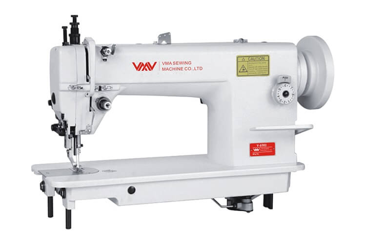
Для тяжёлых материалов, машина с верхним и нижним транспортером (ПЕРЕТОП), максимальная длина стежка — 8 мм, максимальная скорость шитья — 2500 стежков в минуту, подъём лапки 8/13 мм, автоматическая система смазки. Тип иглы 135×17.
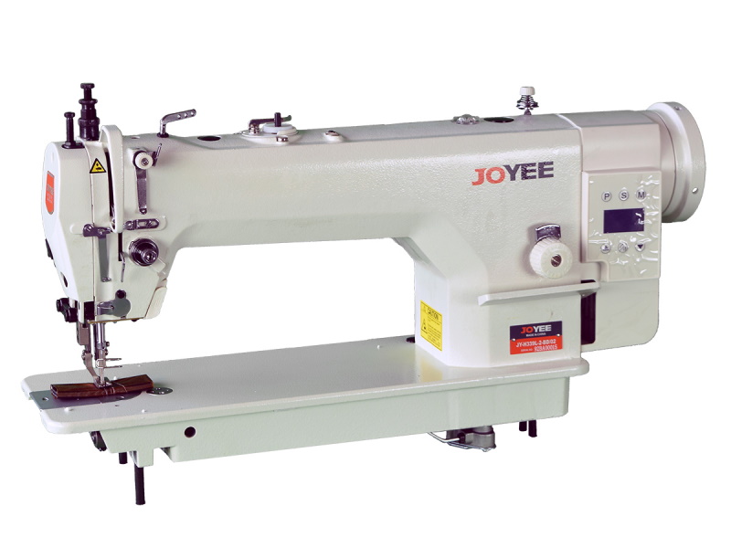
Для тяжёлых материалов, с верхним и нижним транспортером (ПЕРЕТОП), усиленная машина с возможностью работы толстой нитью до №210/9, встроенный серводвигатель, позиционер иглы, встроенная подсветка. УВЕЛИЧЕННЫЙ ВЫЛЕТ РУКАВА 335 ММ, увеличенный челнок, регулятор высоты подъема лапок на толщину материала от 2 до 5,5 мм, подъем внутренней лапки до 8 мм, внешней лапки до 16 мм, длина стежка до 8 мм, скорость шитья 2000 об/мин, автоматическая система смазки. Тип иглы DPx17 №180 – 200.
JOYEE JY-H339L-CX-D4 (НОВАЯ)
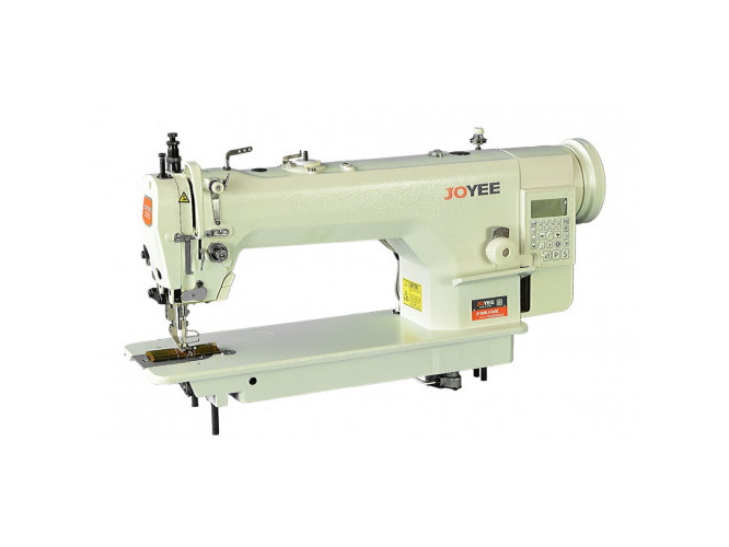
Для тяжёлых материалов, машина с верхним и нижним транспортером (ПЕРЕТОП), усиленная машина с возможностью работы толстой нитью до №210/9, встроенный серводвигатель, позиционер иглы, встроенная подсветка. УВЕЛИЧЕННЫЙ ВЫЛЕТ РУКАВА 335 ММ, увеличенный челнок, регулятор высоты подъема лапок на толщину материала от 2 до 5,5 мм, подъем внутренней лапки до 8 мм, внешней лапки до 16 мм, длина стежка до 8 мм, скорость шитья 2000 об/мин, автоматическая система смазки. Тип иглы DPx17 №180 – 200. Автоматические функции: обрезка нити, закрепка,
позиционер иглы, подъем лапки.
Добро пожаловать в Интернет магазин ПроКапиталист
В связи с резким изменением курсов валют — некоторые цены в магазине могут отличаться от актуальных,
точную цену узнавайте у менеджеров по телефону +7 916 980-0648
Все цены на швейные машины указаны за КОМПЛЕКТ — голова, стол, привод (если не отмечено иное)
Задать вопросы по швейному оборудованию, обсудить преимущества той или иной позиции, а также следить за всеми новостями швейного бизнеса вы можете в группе Procapitalist в Facebook!

Производитель: Joyee
Артикул: JY-H339L-2-CX-BD
ID: 19699-09
Наличие: Есть в наличии
Цена:
55 500 р.
Одноигольная прямострочная швейная машина челночного стежка JOYEE JY-H339L-2-CX-BD с возможностью работы толстой нитью до № 210/9, верхним и нижним транспортером (ПЕРЕТОП) увеличенным челноком и встроенным серводвигателем, обеспечивающим низкое потребление электричества и высокую производительность. Увеличенный челнок.
Назначение: для тяжелых материалов.
Технические характеристики:
— Вылет рукава: 335 мм., увеличенный.
— Регулятор высоты подъема лапок на толщину материала: от 2 до 5,5 мм.
— Подъем внутренней лапки: до 8 мм.
— Внешняя лапка: до 16 мм.
— Длина стежка: до 8 мм.
— Скорость шитья: 2000 об/мин.
— Система смазки: автоматическая.
Цена указана за комплект: голова со встроенным серводвигателем, стол.
| Характеристики промышленной швейной машины | |
| Тип привода | встроенный |
| Тип материала | тяжелые |
| Длина стежка, мм | 8 |
| Тип продвижения | нижний, верхний |
| Скорость шитья | 2000 |
| Тип челнока | увеличенный |
| Тип смазки | автоматическая |
| Высота подъема прижимной лапки, мм | 16 |
| Наличие автоматики | нет |
| Прямострочные челночного стежка | |
| Продвижение материала | Двойное |
| С прямым приводом | С прямым приводом |
Написать отзыв
Ваше Имя:
Ваш отзыв:
Внимание: HTML не поддерживается! Используйте обычный текст.
Оценка: Плохо
Хорошо
Введите код, указанный на картинке: