-
Contents
-
Table of Contents
-
Bookmarks
Quick Links
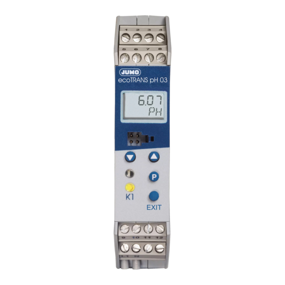
JUMO ecoTRANS pH 03
Microprocessor/transmitter / switching device
for pH value / redox voltage and temperature
Operating manual
20272300T90Z001K000
V2.00/EN/00506536
Related Manuals for JUMO ecoTRANS pH 03
Summary of Contents for JUMO ecoTRANS pH 03
-
Page 1
JUMO ecoTRANS pH 03 Microprocessor/transmitter / switching device for pH value / redox voltage and temperature Operating manual 20272300T90Z001K000 V2.00/EN/00506536… -
Page 3: Table Of Contents
Content Typographical conventions ……6 Warning signs ……… . 6 Note signs .
-
Page 4
Content Calibration ……..40 General information ……..40 9.1.1 When is calibration required? . -
Page 5
Display and LED messages ….. . . 62 12.1 Operating states of JUMO ecoTrans pH 03 ….62 12.2 Underrange . -
Page 6: Typographical Conventions
1 Typographical conventions Warning signs Danger This symbol is used when there may be danger to personnel if the instructions are ignored or not followed correctly! Caution This symbol is used when there may be damage to equipment or data if the instructions are ignored or not followed correctly! Caution This symbol is used where special care is required when handling components…
-
Page 7: Notes
Please assist us in improving these operating instructions where necessary. For technical questions Service hotline: Phone: 0661 6003-300 or 0661 6003-653 Fax: 0661 6003-881300 or 0661 6003-881653 E-mail: Service@jumo.net…
-
Page 8: Identifying The Instrument Version
3.1 Type description (1) Basic type 202723 JUMO ecoTRANS pH 03, Microprocessor/transmitter / switching device for pH value / redox voltage and temperature (2) Output I (pH value / redox voltage) Analog actual value output, freely programmable…
-
Page 9: Mounting
4 Mounting °C ≤ 75 5 Electrical connection The choice of cable, the installation, and the electrical connection must conform to the requirements of VDE 0100 “Regulations on the Installation of High-Voltage Systems with Nominal Voltages below 1000 V” or the appropriate local regulations. To protect the device from static electrical discharge, the user must be electrostatically discharged before touching the instrument!
-
Page 10: Connecting The Sensor
5.1 Connecting the sensor To connect the pH redox electrode, special coaxial lines are recommended as specified by JUMO datasheet 202990. Standard commercial antenna or computer lines with coaxial construction are generally not suitable. They may result in faulty readings or could destroy the pH or redox electrode.
-
Page 11: Customizing The Special Coaxial Line
5.2 Customizing the special coaxial line Example: ~40 mm Strip insulation from the line as shown in the drawing. Remove the black semiconducting layer (2) from the insulation of the inner conductor as indicated. Twist the shield (1) and insulate with a shrink tubing. Insulate the black semiconducting layer with shrink tubing (2) to prevent short circuits.
-
Page 12
Terminal assignment EXIT… -
Page 13
Measurement Terminal assignment Symbol inputs pH electrode Reference system (braiding) Redox Glass electrode/metal combination electrode (inner conductor) electrode pH glass electrode 13 Glass electrode/metal electrode (inner conductor) Metal electrode (with isolated reference electrode) Reference 16 Reference system electrode (with isolated electrodes) Liquid potential (connect only with… -
Page 14
Binary input Outputs Terminal assignment Symbol Analog process value output pH/ redox (galvanically isolated) Analog process value output — temperature (galvanically isolated) Relay Break (SPST-NC) Make (SPST-NO) Ö Power Terminal assignment Symbol supply Power supply (with reverse polarity protection) DC 20 to 30 V… -
Page 15: Commissioning
6 Commissioning 6.1 Brief description of the instrument The instrument measures and, depending on the configuration, regulates the pH or redox voltage in aqueous solutions. The range applications includes general water wastewater management, measuring drinking and wastewater, process water, surface and ocean water, swimming pool and fountain water, and professional aquariums, etc.
-
Page 16: Block Diagram
Note: After the instrument is started, the output signal is 0 V or 0 mA. The relay is in idle state (inactive). After about 2 seconds, the JUMO ecoTRANS pH 03 begins working according to the configuration.
-
Page 17: Adjusting / Changing Instrument Functions
7 Adjusting / changing instrument functions Changes can be made in the setup program or with the JUMO ecoTRANS pH 03 keys. 7.1 Process value display The process value display can be either — in static mode or in — alternating mode…
-
Page 18: Operation
7.2 Operation The instrument can be operated on different levels. Access to all levels (except the user level) is protected by different codes On the User level (USER) all parameters can be viewed and/or modified depending on user rights (see Enable level). On the Calibration level (CALIB) the electrode zero point (intercept point) and/or the electrode slope can be calibrated.
-
Page 19
— To increase or reduce the value, press the UP or DOWN key. — The value can then be accepted with the P key. — The EXIT key is used to cancel the entry and switch to the next higher level. -
Page 20: Selecting Levels
7.4 Selecting levels Process value display > 2 seconds EXIT Selection level EXIT USER (Operator level) EXIT ADMIN (Administrator level) EXIT RIGHT (Enable level) EXIT CALIB (Calibration level) Timeout (automatically jumps back after 60 sec. with no activity). See Section 7.5 «User level (USER)», page 21. See Section 7.6 «Administrator level (ADMIN)», page 22.
-
Page 21: User Level (User)
7.5 User level (USER)
-
Page 22: Administrator Level (Admin)
7.6 Administrator level (ADMIN)
-
Page 23: Enable Level (Right)
7.7 Enable level (RIGHT)
-
Page 24: Calibration Level (Calib)
7.8 Calibration level (CALIB) CALIB CODE See Section 9.5.1 «One-point calibration (zero point)», page 44 NULL See Section 9.5.2 «Two-point calibration (zero point and slope)», page 45 SLOPE The timeout function is not active during calibration! See Section 9 «Calibration», page 40.
-
Page 25: Configurable Parameters
8 Configurable parameters Parameters can be set with the setup program or on the instrument. Since some parameters are independent of each other, it may be necessary when one parameter is changed to adjust others as well. Example: When the measurement variable is changed (from pH to redox voltage or vice versa) the display format, setpoints, and other parameters are adjusted.
-
Page 40: Calibration
9 Calibration 9.1 General information The zero point (intercept) and slope of pH sensors stray from copy to copy. During the service life of the sensor, up to the time it must be replaced by a new sensor, the zero point and slope change. To allow for precise measurements, the transmitter must be adjusted (calibrated) to the current sensor parameters.
-
Page 41: Starting Calibration From The Calibration Level «Calib
Calibration can be cancelled at any time with the EXIT key. Old calibration data will not be lost. Calibration is performed using the instrument keys. The zero point and slope of a sensor can also be entered manually. This should only be done in exceptional cases.
-
Page 42: Canceling Calibration And Error Messages
9.3 Canceling calibration and error messages Calibration can be cancelled at any time with the EXIT key. Old calibration data will not be lost. During the calibration process, the transmitter calculates the electrode parameters zero point and if applicable slope. If the calculated values fall outside the permissible parameter limits, an error message is generated.
-
Page 43: Acknowledging Errors
The parameter limits for NULL and SLOPE have been violated and/ or the two calibration points Ref.1 and Ref.2 are too close to each other. For two-point calibration of a pH sensor, the minimum spacing is 2 pH. For two-point calibration of a redox sensor, the minimum spacing is 2 mV.
-
Page 44: Selecting Two-Point Calibration
9.4.2 Selecting two-point calibration Press the key and select CAL 2-PT. For more details see Section 9.5.2 «Two-point calibration (zero point and slope)», page 45. 9.5 Calibrating a pH measurement chain 9.5.1 One-point calibration (zero point) Confirm the selection with Display or editing option of the buffer temperature.
-
Page 45: Two-Point Calibration (Zero Point And Slope)
Flashing Enter the actual buffer value with and confirm with The calculated zero point of the measurement chain appears. Accept the value with or press to cancel the calibration. EXIT The instrument goes into measurement mode. If an error message appears, see Section 9.3 «Canceling calibration and error messages», page 42.
-
Page 46
Confirm the selection with Display and editing option of the buffer temperature. Confirm the selection with The first reference value is then measured. Immerse the measurement chain in the first buffer (for example pH 7.00) Wait until the measurement value has stabilized. Confirm the measurement value with Flashing Enter the actual buffer value with… -
Page 47
Remove the measurement chain from the first buffer and rinse with distilled water. Immerse the measurement chain in the second buffer (for example pH 4.00) Wait until the measurement value has stabilized. Confirm the measurement value with Flashing Enter the actual buffer value with confirm with The calculated zero point (top line) and the calculated slope (bottom line) appear. -
Page 48: Ph Antimony Measurement Chain
9.6 pH antimony measurement chain Antimony measurement chains are calibrated similarly to «normal» pH measurement chains, see Section 9.5 «Calibrating a pH measurement chain», page 44. 9.7 Redox measurement chain 9.7.1 General information The instrument offers two calibrating options for adjusting it to the redox measurement chain.
-
Page 49
The reference value is then measured. Wait until the measurement value has stabilized. Confirm the measurement value with Flashing Enter the actual buffer value with confirm with The calculated zero point of the measurement chain appears. Accept the value with or press to cancel the calibration. -
Page 50: Two-Point Calibration
9.7.3 Two-point calibration In this type of calibration the display range can be scaled freely from 0 to 100%. Example: A span of -10 mV … +1000 mV can be scaled to 0 … 100% werden. The zero point can fall within the range of -999 …
-
Page 51
Enter the desired value with (for example 20) and confirm with Remove the measurement chain from the first solution and rinse with distilled water. Immerse the measurement chain in the second solution (for example 295 mV). Wait until the measurement value has stabilized. Confirm the measurement value with Flashing Enter the desired value with… -
Page 52: Analog Output
10 Analog output Analog outputs are configured on the user level (USER) or on the administrator level (ADMIN) in PH.OUT redox output) TE.OUT (temperature output); see Section 7.5 «User level (USER)», page 21. 10.1 Behavior of the output signal during calibration Two options are possible, «Concurrent»…
-
Page 53: Output Signal In Case Of Error
10.3 Output signal in case of error Depending on the configuration, the output signal may assume the «LOW» or «HIGH» state in case of error. Output signal Output signal Output signal nominal HIGH 0…20 mA 22.0 mA 0 mA 4…20 mA 22.0 mA 3.4 mA 0…10 V…
-
Page 54: Relay Output
11 Relay output 11.1 Relay behavior Depending on the setting, the JUMO ecoTRANS pH 03 monitors a limit value. 11.2 Binary output 1 (submenu «BIN.1») Setting options = No function (default setting) = Window contact main value (active inside a window)
-
Page 55
Contact function for settings 1 and 5 Hysteresis HYS.1. Distance DST.1 Switching point ALAR.1 Contact function for settings 2 and 6 Hysteresis HYS.1. Distance DST.1 Switching point ALAR.1… -
Page 56
Contact function for settings 3 and 7 Hysteresis HYS.1. Switching point ALAR.1 Contact function for settings 4 and 8 Hysteresis HYS.1. Switching point ALAR.1… -
Page 57: Manual Mode Of The Relay Output
11.3 Manual mode of the relay output For test purposes or when starting up systems, a constant signal can be generated by the transmitter. Manual mode can be set with parameter: USER / BIN.1 / SIM.1 to = inactive = active => LED «K1» is lit = No manual mode.
-
Page 58: Behavior Of The Relay During Calibration
After «Supply voltage On» manual mode is always deactivated. 11.4 Behavior of the relay during calibration The behavior of the relay with the parameter: USER / BIN.1 / CAL.1 set to Relay inactive Relay active Relay unchanged (during calibration the relay status remains set to the status that was valid before the calibration process) 11.5 Pulse function of the relay output The limit comparator is reset after an adjustable «pulse time.»…
-
Page 59
Triggering condition is longer than pulse duration Triggering condition Time Pulse contact Time Pulse duration T.PUL1 Triggering condition is shorter than pulse duration Triggering condition Time Pulse contact Time Pulse duration T.PUL1… -
Page 60: Behavior Of The Relay In Case Of Error
11.6 Behavior of the relay in case of error The behavior of the relay can be adjusted with the following parameters: USER / BIN.1 and ERR.1 set to Relay inactive Relay active Relay unchanged («frozen»: the relay status remains set to the status that was valid before the error) Function pH value…
-
Page 61
Limit comparator of pH value/redox voltage with active temperature compensation — Underrange pH value/redox voltage — Overrange pH value/redox voltage — Underrange temperature — Overrange temperature Limit comparator — temperature — Underrange temperature — Overrange temperature Calibration timer — Timeout… -
Page 62: Display And Led Messages
12 Display and LED messages 12.1 Operating states of JUMO ecoTrans pH 03 Two LED indicate operating states Instrument status Red LED (top) Yellow LED (bottom) Normal mode On if LC1 is active Error Flashing On if LC1 is active Initialization 12.2 Underrange…
-
Page 63: Short-Circuit
If no automatic temperature compensation or temperature measurement is required parameter SENS.T must be set accordingly; see Section 8.1.2 «Measurement input — temperature (submenu «TEMP»)», page 28. 12.5 Short-circuit 12.6 Initialization of dependent parameters After a parameter has been changed, other dependent parameters are automatically changed.
-
Page 64: Operation Via Setup Interface
13 Operation via setup interface EXIT (1) JUMO ecoTRANS pH 03 (2) PC interface line (optional accessory) (3) JUMO PC setup software, multilingual D / GB / F (optional accessory) (4) PC or Notebook with USB interface ® ® operating system: Windows 2000…
-
Page 65: Operation With Pc Setup Program
13.1 Operation with PC setup program (1) Navigation tree The navigation tree provides fast access (double click) to individual setting options. (2) Diagnostics window As soon as a connection is established with an instrument, current data is displayed here. (3) Working area Clicking the arrow ( ) shows possible settings.
-
Page 66: Technical Data
14 Technical data Inputs Analog input 1 (pH / redox) — Electrodes — Glass or metal electrodes with isolated reference electrode — Antimony electrode Measurement ranges for pH / redox -2 … 16 pH or -1500 … +1500 mV Accuracy for pH / redox ±…
-
Page 67
≤ 400 Ω or 0(4) … 20mA load ≤ 400 Ω 20 … (4)0mA load galvanically isolated from inputs: ΔU ≤ 30V AC or ΔU ≤ 50 V DC Scope of scaling at least 10% of the scope of the measurement range deviation from the characteristic curve of the output signal ≤… -
Page 68
Supply DC 20 … 30 V, residual ripple<5%, power consumption≤ 4 W, with reverse polarity protection. Operates only on SELV or PELV circuits. Electrical connection Screw terminals up to 2.5 mm Operating temperature range 0 … +50°C Functional temperature range -10 …… -
Page 69: Environment/Disposal
Mounting On DIN rail 35mm x 7.5mm to DIN EN 60 715 Installation position Weight Approx. 150g 15 Environment/disposal Defective instruments can be sent to JUMO for proper disposal.
-
Page 72
JUMO GmbH & Co. KG Street address: Moritz-Juchheim-Straße 1 36039 Fulda, Germany Delivery address: Mackenrodtstraße 14 36039 Fulda, Germany Postal address: 36035 Fulda, Germany Phone: +49 661 6003-0 Fax: +49 661 6003-607 Email: mail@jumo.net Internet: www.jumo.net JUMO Instrument Co. Ltd.
39
9 Calibration
9.1 General information
The zero point (intercept) and slope of pH sensors stray from copy to copy. During the service life of the sensor, up to the time it must be replaced by a new sensor, the zero point and slope change. To allow for precise measurements, the transmitter must be adjusted
(calibrated) to the current sensor parameters. The calibration is performed using buffer solutions.
Only the zero point needs to be calibrated for redox sensors.
9.1.1 When is calibration required?
The electrochemical sensors should be cleaned and the transmitter should be calibrated at regular intervals (depending on the measuring medium)!
With the correct wiring of device and sensor, and correct configuration of the device, a measurement without calibration should be possible.
If this is not the case, influencing factors such as short circuit, open circuit, EMC and flow conditions should also be considered.
9.2 Activating and starting calibration mode
During the calibration process, the display flashes.
The analog outputs respond as they were calibrated on the USER LEVEL / ANALOG OUTPUT x /
FOR CALIBRATION.
The response of the relay depends on the configuration of the switching output!
40
Calibration can be cancelled at any time with the EXIT key. Old calibration data will not be lost.
Calibration is performed using the instrument keys.
The zero point and slope of a sensor can also be entered manually. This should only be done in exceptional cases. Some sensors come with a test report that specifies the zero point and slope. These values simply provided documentation that the sensor was in proper condition upon delivery. Since these values change during storage, they are not suitable for manual entry. We always advise performing calibration with buffer solutions.
The timeout function is not active during calibration!
9.2.1 Starting calibration from the calibration level «CALIB»
Use the menu to switch to the calibration level (see
Section 7.4 «Selecting levels», page 20 and Section
7.8 «Calibration level (CALIB)», page 24).
✱
P
Press and hold (for more than 2 sec) / then select CALIB.
✱
P
Press and hold (for less than 1 sec) / then enter code 110.
✱ Confirm with
P
,
continue with Section 9.4 «One-point or two-point calibration», page 43.
9.2.2 Starting calibration with the hot key (rapid access)
Activation of the calibration mode by rapid access must be previously enabled:
P
> Press and hold for 2 seconds / Set ADMIN / CAL /
CA.LVL to 1.
✱ Press the
P
and keys,
continue with Section 9.4 «One-point or two-point calibration», page 43.
41
9.3 Canceling calibration and error messages
Calibration can be cancelled at any time with the EXIT key. Old calibration data will not be lost.
During the calibration process, the transmitter calculates the electrode parameters zero point and if applicable slope. If the calculated values fall outside the permissible parameter limits, an error message is generated.
For the permitted value ranges of parameters NULL and SLOPE see
Section 8.1.1 «Measurement input — main value (submenu «PH»)», page 26.
9.3.1 Zero point error
Parameter limits for NULL have been violated.
9.3.2 Slope error
Parameter limits for SLOPE have been violated.
9.3.3 General error during calibration
42
The parameter limits for NULL and SLOPE have been violated and/ or the two calibration points Ref.1 and Ref.2 are too close to each other.
For two-point calibration of a pH sensor, the minimum spacing is
2 pH.
For two-point calibration of a redox sensor, the minimum spacing is
2 mV.
The greater the spacing, the more accurate the calibration.
9.3.4 Acknowledging errors
✱ Press the
P
keys or EXIT.
The error message is deleted.
The faulty parameters NULL and/or SLOPE are not saved.
The instrument continues working with old calibration data.
9.3.5 Additional measures
✱ Check the quality and condition (age) of the buffer solutions.
✱ Check whether the sensor is dirty or needs to be replaced.
✱ Check whether the sensor plug is moist or the wiring is faulty.
✱ Observe the minimum spacings for buffer or reference values.
9.4 One-point or two-point calibration
For one-point calibration, the transmitter is only adjusted to the zero point of the sensor.
In two-point calibration the transmitter is adjusted to both the zero point of the sensor and its slope. We expressly recommend twopoint calibration!
9.4.1 Selecting one-point calibration
Select CAL I-PT.
For more details see Section 9.5.1 «One-point calibration (zero point)», page 44.
43
9.4.2 Selecting two-point calibration
Press the key and select CAL 2-PT.
For more details see Section 9.5.2 «Two-point calibration (zero point and slope)», page 45.
9.5 Calibrating a pH measurement chain
9.5.1 One-point calibration (zero point)
✱ Confirm the selection with
P
.
Display or editing option of the buffer temperature.
✱ Confirm the selection with
P
.
The first reference value is then measured.
✱ Wait until the measurement value has stabilized.
Confirm the measurement value with
P
.
44
Flashing
✱ Enter the actual buffer value with
or and confirm with
P
.
The calculated zero point of the measurement chain appears.
✱ Accept the value with
P
or press
EXIT
to cancel the calibration.
The instrument goes into measurement mode.
If an error message appears, see Section 9.3
«Canceling calibration and error messages», page 42.
9.5.2 Two-point calibration (zero point and slope)
Calibrate zero point and slope.
The buffer solutions (reference solutions) used for calibration must differ by at least 2 pH!
During the calibration, the temperature of the two buffer solutions must be identical and remain constant!
45
✱ Confirm the selection with
P
.
Display and editing option of the buffer temperature.
✱ Confirm the selection with
P
.
The first reference value is then measured.
✱ Immerse the measurement chain in the first buffer (for example pH 7.00)
✱ Wait until the measurement value has stabilized.
Confirm the measurement value with
P
.
Flashing
✱ Enter the actual buffer value with
or and confirm with
P
.
46
✱ Remove the measurement chain from the first buffer and rinse with distilled water.
✱ Immerse the measurement chain in the second buffer (for example pH 4.00)
✱ Wait until the measurement value has stabilized.
Confirm the measurement value with
P
.
Flashing
✱ Enter the actual buffer value with
or and confirm with
P
.
The calculated zero point (top line) and the calculated slope (bottom line) appear.
✱ Accept the values with
P
or press
EXIT
to cancel the calibration.
The instrument goes into measurement mode.
If an error message appears, see Section 9.3
«Canceling calibration and error messages», page 42.
47
9.6 pH antimony measurement chain
Antimony measurement chains are calibrated similarly to «normal»
pH measurement chains, see Section 9.5 «Calibrating a pH measurement chain», page 44.
9.7 Redox measurement chain
9.7.1 General information
The instrument offers two calibrating options for adjusting it to the redox measurement chain.
— One-point calibration
If «mV» was configured as UNIT.
— Two-point calibration
If «%» was configured as UNIT.
The display flashes during calibration.
The analog outputs respond the same way as on
USER LEVEL / ANALOG OUTPUT x / FOR
CALIBRATION.
The response of the relay depends on the configuration of the switching output!
)
9.7.2 One-point calibration (recommended calibration)
Calibration of the zero point.
✱ Confirm the selection with
P
.
✱ Rinse off the measurement chain with distilled water or clean if necessary (see operating instructions for electrode).
✱ Immerse the measurement chain in the test solution (e.g. 468 mV).
48
The reference value is then measured.
✱ Wait until the measurement value has stabilized.
✱ Confirm the measurement value with
P
.
Flashing
✱ Enter the actual buffer value with
or and confirm with
P
.
The calculated zero point of the measurement chain appears.
Accept the value with
P
or press
EXIT
to cancel the calibration.
The instrument goes into measurement mode.
If an error message appears, see Section 9.3
«Canceling calibration and error messages», page 42.
49
)
9.7.3 Two-point calibration
In this type of calibration the display range can be scaled freely from
0 to 100%.
Example:
A span of -10 mV … +1000 mV can be scaled to 0 … 100% werden.
The zero point can fall within the range of
-999 … +999 mV.
Two different reference fluids must be used for the calibration. The redox voltage of a measurement solution is not temperature-dependent!
Confirm the selection with
P
.
The first reference value is then measured.
✱ Immerse the measurement chain in the first solution (for example
59 mV)
✱ Wait until the measurement value has stabilized.
Confirm the measurement value with
P
.
Flashing
50
✱ Enter the desired value with
or (for example 20) and confirm with
P
.
✱ Remove the measurement chain from the first solution and rinse with distilled water.
✱ Immerse the measurement chain in the second solution (for example 295 mV).
✱ Wait until the measurement value has stabilized.
Confirm the measurement value with
P
.
Flashing
✱ Enter the desired value with
or (for example 80) and confirm with
P
.
✱ The calculated zero point (top line in mV) and the calculated slope (bottom line) appear.
Accept the values with
P
or press
EXIT
to cancel the calibration.
The instrument goes into measurement mode.
If an error message appears, see Section 9.3
«Canceling calibration and error messages», page 42.
51
10 Analog output
Analog outputs are configured on the user level
(USER) or on the administrator level (ADMIN) in
PH.OUT (pH or redox output) and TE.OUT
(temperature output); see Section 7.5 «User level
(USER)», page 21.
10.1 Behavior of the output signal during calibration
Two options are possible, «Concurrent» and «Unchanged»
(constant).
10.2 Behavior of the output signal in case of error
If one of the following errors occurs, the output signal assumes the
defined status (see Section 10.3 «Output signal in case of error», page 53):
Analog output of pH value / redox voltage with non-active temperature compensation
— Underrange pH value / redox voltage
— Overrange pH value / redox voltage
Analog output of pH value / redox voltage with active temperature compensation
— Underrange pH value / redox voltage
— Overrange pH value / redox voltage
— Underrange temperature
— Overrange temperature
Analog output — temperature
— Underrange temperature
— Overrange temperature
52
10.3 Output signal in case of error
Depending on the configuration, the output signal may assume the
«LOW» or «HIGH» state in case of error.
Output signal nominal
0…20 mA
4…20 mA
0…10 V
2…10 V
Output signal
HIGH
22.0 mA
22.0 mA
10.7 V
10.7 V
Output signal
LOW
0 mA
3.4 mA
0 V
1.4 V
10.4 Output signal when leaving the scaling range
When leaving the scaling range, the output returns a proportional signal up to a defined limit (in compliance with NAMUR NE43). The limits are listed in the table below:
Value below scaling range
0.0 mA
3.8 mA
0.0 V
20.5 mA
20.5 mA
10.2 V
1.8 V
10.2 V
In the scaling range
0…20 mA
4…20 mA
0…10 V
20…0 mA
20…4 mA
10…0 V
2…10 V
10…2 V
Scaling range was exceeded
20.5 mA
20.5 mA
10.2 V
0.0 mA
3.8 mA
0.0 V
10.2 V
1.8 V
10.5 Manual mode of the analog output
For test purposes or startup, a constant analog signal can be generated by the instrument
(see also Section 11.3 «Manual mode of the relay output», page
57).
After a power supply failure, manual mode is deactivated.
53
11 Relay output
11.1 Relay behavior
Depending on the setting, the JUMO ecoTRANS pH 03 monitors a limit value.
11.2 Binary output 1 (submenu «BIN.1»)
Setting options
0
= No function (default setting)
1 = Window contact main value (active inside a window)
2 = Window contact main value (active outside a window)
3 = Max contact main value (normally open (NO), similar to LK7)
4 = Min contact main value (normally closed (NC), similar to LK8)
5 = Window contact temperature (active inside a window)
6 = Window contact temperature (active outside a window)
7 = Max contact temperature (normally open (NO), similar to
LK7)
8 = Min contact temperature (normally closed (NC), similar to
LK8)
9 = Error output (every device error causes the relay to switch)
10 = Calibration timer elapsed
54
Contact function for settings 1 and 5
Hysteresis
HYS.1.
On
Off
Distance
DST.1
Switching point
ALAR.1
Contact function for settings 2 and 6
Hysteresis
HYS.1.
On pH
Off
Distance
DST.1
Switching point
ALAR.1
pH
55
Contact function for settings 3 and 7
Hysteresis
HYS.1.
On
Off
Switching point
ALAR.1
pH
Contact function for settings 4 and 8
Hysteresis
HYS.1.
On
Off
Switching point
ALAR.1
pH
56
11.3 Manual mode of the relay output
For test purposes or when starting up systems, a constant signal can be generated by the transmitter.
Manual mode can be set with parameter: USER / BIN.1 / SIM.1 to
0
1
2
= inactive
= active => LED «K1» is lit
= No manual mode.
Indication of manual mode
About 3
If one of the outputs is in manual mode, this is indicated in the change to process value display by an «S» or «-«.
S The relevant output is in manual mode.
The relevant output is not in manual mode.
1 2 3
1st place Analog output — pH/redox voltage
2nd place Analog output — temperature
3rd place Binary output 1
In the example above, the analog temperature output is in manual mode. No other outputs are in manual mode.
When the user exits manual mode, the output signal immediately assumes the value proportional to the pH value/redox voltage or the temperature process value.
57
After «Supply voltage On» manual mode is always deactivated.
11.4 Behavior of the relay during calibration
The behavior of the relay with the parameter:
USER / BIN.1 / CAL.1 set to
0 = Relay inactive
1 = Relay active
2 = Relay unchanged
(during calibration the relay status remains set to the status that was valid before the calibration process)
11.5 Pulse function of the relay output
The limit comparator is reset after an adjustable «pulse time.» The parameter for this is: USER / BIN.1 / T.PUL1 .
It can be set from 0 = 0 seconds (no pulse function) to 999 = 999 seconds.
LED «K1» is lit red as long as the switching condition is met.
No OFF delay is possible in pulse mode.
58
Triggering condition is longer than pulse duration
Triggering condition
On
Off
Time
Pulse contact
On
Off
Time
Pulse duration
T.PUL1
Triggering condition is shorter than pulse duration
Triggering condition
On
Off
Time
Pulse contact
On
Off
Time
Pulse duration
T.PUL1
59
11.6 Behavior of the relay in case of error
The behavior of the relay can be adjusted with the following parameters:
USER / BIN.1 and ERR.1 set to
0 = Relay inactive
1 = Relay active
2 = Relay unchanged
(«frozen»: the relay status remains set to the status that was valid before the error)
Function pH value redox voltage
Underrange
Overrange
Temperature
Underrange
Overrange
Limit comparator pH/redox voltage without temperature compensation
Limit comparator pH/redox voltage with temperature compensation
Limit comparator temperature
Calibration timer elapsed
Error output x x x x x x x x x x x x x x x x
11.7 Error detection
The relay output is active for the following errors:
Limit comparator for pH value/redox voltage with non-active temperature compensation
— Underrange pH value/redox voltage
— Overrange pH value/redox voltage
60
Limit comparator of pH value/redox voltage with active temperature compensation
— Underrange pH value/redox voltage
— Overrange pH value/redox voltage
— Underrange temperature
— Overrange temperature
Limit comparator — temperature
— Underrange temperature
— Overrange temperature
Calibration timer
— Timeout
61
12 Display and LED messages
12.1 Operating states of JUMO ecoTrans pH 03
Two LED indicate operating states
Instrument status Red LED (top)
Normal mode Off
Error
Initialization
Flashing
Off
12.2 Underrange
Yellow LED (bottom)
On if LC1 is active
On if LC1 is active
Off
Value is below lower measurement range limit (ORP means redox).
12.3 Overrange
Measurement range exceeded (ORP means redox).
12.4 Broken sensor
Broken sensor, wrong or no temperature sensor connected;
see Section 8.1.2 «Measurement input — temperature
(submenu «TEMP»)», page 28.
62
If no automatic temperature compensation or temperature measurement is required parameter SENS.T must be set
accordingly; see Section 8.1.2 «Measurement input — temperature (submenu «TEMP»)», page 28.
12.5 Short-circuit
12.6 Initialization of dependent parameters
After a parameter has been changed, other dependent parameters are automatically changed.
Please check all dependent parameters!
12.7 Calibration timer elapsed
Depending on specifications (for example of the equipment manufacturer), calibration of the measurement chain should be performed.
After a correct calibration, the calibration timer is reset and automatically restarted.
63
13 Operation via setup interface
(1)
(4)
(2)
P
K1
EXIT
(3)
(1) JUMO ecoTRANS pH 03
(2) PC interface line (optional accessory)
(3) JUMO PC setup software, multilingual D / GB / F (optional accessory)
(4) PC or Notebook with USB interface operating system: Windows 2000
®
,
NT
®
4.0 and up, Windows Vista
®
Windows XP
® or Windows
64
13.1 Operation with PC setup program
(1)
(3)
(2)
(1) Navigation tree
The navigation tree provides fast access (double click) to individual setting options.
(2) Diagnostics window
As soon as a connection is established with an instrument, current data is displayed here.
(3) Working area
Clicking the arrow ( ) shows possible settings.
Double clicking the text opens the appropriate editing window.
65
14 Technical data
Inputs
Analog input 1 (pH / redox)
— Electrodes
— Glass or metal electrodes with isolated reference electrode
— Antimony electrode
Measurement ranges for pH / redox
-2 … 16 pH or
-1500 … +1500 mV
Accuracy for pH / redox
± 1% of the measurement range
Analog input 2 (temperature)
— Resistance thermometer Pt100 or Pt1000
The temperature sensor can be connected in a 2-wire circuit.
Measurement display can be switched between °C / °F
Temperature offset for analog input 2
A process value can be corrected by an offset in the range from —
20 … +20°C.
Temperature measurement range
-10 … +150°C or 14 … 302°F
Deviation from characteristic temperature curve
for Pt 100 / Pt 1000:
≤
1.5 K
Outputs
Two analog outputs:
Freely configurable:
0(2) … 10V
10 … (2)0V
R load
R load
≥
2 k
Ω
or
≥
2 k
Ω
or else
66
0(4) … 20mA R load
20 … (4)0mA R load
≤
400
Ω or
≤
400
Ω galvanically isolated from inputs:
Δ
U
≤
30V AC or
Δ
U
≤
50 V DC
Scope of scaling at least 10% of the scope of the measurement range
deviation from the characteristic curve of the output signal
≤
0.075% of the measurement range
Relay output:
Switching contact switching capacity: 8 A, 250 V AC or 8 A, 24 V DC with resistive load contact life: > 100,000 operations at normal load
Key general parameters
A/D converter
14-bit resolution
Sampling time
500ms = 2 measurements / second
Effect of ambient temperature
≤
0.6% / 10 K
Measuring circuit monitoring
Input 1(main value): out-of-range
Input 2 (temperature): out-of-range, sensor short circuit, broken sensor.
In case of error, the outputs assume a defined
(configurable) state.
Data backup
EEPROM
67
Supply
DC 20 … 30 V, residual ripple<5%, power consumption
≤
4 W, with reverse polarity protection.
Operates only on SELV or PELV circuits.
Electrical connection
Screw terminals up to 2.5 mm
2
Operating temperature range
0 … +50°C
Functional temperature range
-10 … +60°C
Storage temperature range
-20 … +75°C
Climatic rating
Rel. humidity
≤
75% no condensation
Enclosure protection (complies with EN 60 529)
IP 20
Electrical safety
Complies with EN 61 010 air gaps and creep zones for
— Overvoltage category II
— Pollution degree 2
Electromagnetic compatibility
Complies with EN 61 326
Interference immunity:To industrial requirements
Interference emission:Class B
Enclosure
DIN rail enclosure made of PC (polycarbonate)
68
Mounting
On DIN rail 35mm x 7.5mm to DIN EN 60 715
Installation position
Any
Weight
Approx. 150g
15 Environment/disposal
Defective instruments can be sent to JUMO for proper disposal.
69
70
JUMO GmbH & Co. KG
Street address:
Moritz-Juchheim-Straße 1
36039 Fulda, Germany
Delivery address:
Mackenrodtstraße 14
36039 Fulda, Germany
Postal address:
36035 Fulda, Germany
Phone: +49 661 6003-0
Fax: +49 661 6003-607
Email: [email protected]
Internet: www.jumo.net
JUMO Instrument Co. Ltd.
JUMO House
Temple Bank, Riverway
Harlow, Essex CM 20 2DY, UK
Phone: +44 1279 63 55 33
Fax: +44 1279 62 50 29
Email: [email protected]
Internet: www.jumo.co.uk
JUMO Process Control, Inc.
6733 Myers Road
East Syracuse, NY 13057, USA
Phone: +1 315 437 5866
Fax: +1 315 437 5860
Email: [email protected]
Internet: www.jumousa.com

- Возможность переключения с рН на мВ (редокс-потенциал)
- Простое подключение сенсоров с помощью винтовых зажимов
- Асимметричное и симметричное подключение рН-метрических цепей
- Релейный переключающий контакт
- Возможен контроль температуры среды
Описание
Прибор измеряет и регулирует – в зависимости от конфигурации – величину pH или редокс-потенциал в водных растворах. Типичные области применения – общая водоподготовка, измерения в питьевой, сточной и технологической воде, измерения в поверхностной и морской воде, бассейны, профессиональная аквариумистика, различные технологические процессы.
Измерительный преобразователь имеет два аналоговых входа. Первый аналоговый вход (основной вход для величины pH или редокс-потенциала) предусмотрен для подключения комбинированных или раздельных электродов. К прибору можно также подключать сурьмяные электроды. Ко второму аналоговому входу может подключаться термометр сопротивления Pt100 или Pt1000.
В распоряжении также имеются до двух аналоговых выходов и одно реле — переключающий контакт. Аналоговые выходы гальванически развязаны и поставлены в соответствие входам. Релейному контакту может быть поставлена в соответствие основная измеряемая величина (величина pH или редокс-потенциал) или температура.
Настройка и конфигурация прибора осуществляется с помощью кнопок и интегрированного ЖК-дисплея. Альтернативно настройку и конфигурацию можно очень удобно проводить с помощью ноутбука или ПК, подключенного к setup-интерфейсу прибора, и русифицированной setup-программы (опция). С помощью setup-программы можно также делать распечатку данных конфигурации; это облегчает процесс документирования.
Приборы поставляются с калибровочным сертификатом, в котором отражены информация о приборе и данные настройки.
Особенности
- Возможность переключения с рН на мВ (редокс-потенциал)
- Простое подключение сенсоров с помощью винтовых зажимов
- асимметричное и симметричное подключение рН-метрических цепей
- Два гальванически изолированных аналоговых выхода 0(4)… 20 мА / 0(2)… 10 В, произвольно конфигурируемых как выход действительного значения рН, редокс-потенциала или температуры
- Релейный переключающий контакт
- Возможен контроль температуры среды
- Простая процедура калибровки, сопровождаемая подсказками
- Тройная гальваническая развязка (вход, выход и напряжение питания гальванически изолированы друг от друга)
- Для монтажа на DIN-рейку
- Таймер калибровки
- Калибровочный сертификат в стандартном объеме поставки
- Аналогичные товары
Вся информация на сайте о товарах и ценах носит справочный характер и не является публичной офертой. Производитель оставляет за собой право изменять характеристики товара, его внешний вид и комплектность без предварительного уведомления продавца
Content
9
Calibration . . . . . . . . . . . . . . . . . . . . . . . . . . . . . . . . . . . . 40
9.1
General information . . . . . . . . . . . . . . . . . . . . . . . . . . . . . . . . . . . . . 40
9.2
9.3
9.3.1 Zero point error . . . . . . . . . . . . . . . . . . . . . . . . . . . . . . . . . . . . . . . . . 42
9.3.2 Slope error . . . . . . . . . . . . . . . . . . . . . . . . . . . . . . . . . . . . . . . . . . . . 42
9.3.5 Additional measures . . . . . . . . . . . . . . . . . . . . . . . . . . . . . . . . . . . . . 43
9.4
9.5
9.6
9.7
9.7.1 General information . . . . . . . . . . . . . . . . . . . . . . . . . . . . . . . . . . . . . 48
10
Analog output . . . . . . . . . . . . . . . . . . . . . . . . . . . . . . . . . . 52
10.1
10.2
10.3
10.4
10.5
11
Relay output . . . . . . . . . . . . . . . . . . . . . . . . . . . . . . . . . . . 54
11.1
Relay behavior . . . . . . . . . . . . . . . . . . . . . . . . . . . . . . . . . . . . . . . . . 54
11.2
11.3
11.4
11.5
11.6
11.7
Error detection . . . . . . . . . . . . . . . . . . . . . . . . . . . . . . . . . . . . . . . . . 60
. . . . . . . . . . . . . . . . . . . 42
. . . . . . . . . . . . . . . . . . . . . . . . . 43
. . . . . . . . . . . . . . . . . . . . . . . 44
. . . . . . . . . . . . . . . . . . . . . . . . . . . . . 53