-
Contents
-
Table of Contents
-
Bookmarks
Quick Links
JUMO LOGOSCREEN 600
Paperless Recorder with Touchscreen
Brief Instructions
70652000T97Z001K000
V6.00/EN/00625186
Related Manuals for JUMO LOGOSCREEN 600
Summary of Contents for JUMO LOGOSCREEN 600
-
Page 1
JUMO LOGOSCREEN 600 Paperless Recorder with Touchscreen Brief Instructions 70652000T97Z001K000 V6.00/EN/00625186… -
Page 3: Table Of Contents
Contents Introduction …………7 Safety information .
-
Page 4
Contents 4.4.3 Analog outputs 1 and 2 (options 1 and 2) ……… . 28 4.4.4 Digital inputs/outputs 1 to 12 (option 3) . -
Page 5
Contents 6.1.6 Interfaces …………..74 6.1.7 Screen . -
Page 6
Contents… -
Page 7: Introduction
1 Introduction Safety information 1.1.1 Warning symbols DANGER! This symbol indicates that personal injury caused by electrical shock may occur if the re- spective precautionary measures are not carried out. WARNING! This symbol in connection with the signal word indicates that personal injury may occur if the respective precautionary measures are not carried out.
-
Page 8: Intended Use
1 Introduction 1.1.3 Intended use The device is designed for use as a paperless recorder in an industrial environment as speci- fied in the technical data. Other uses or uses beyond those defined are not viewed as intended uses. The device has been manufactured in compliance with applicable standards and directives as well as applicable safety regulations.
-
Page 9: Acceptance Of Goods, Storage, And Transport
1 Introduction Acceptance of goods, storage, and transport 1.2.1 Checking the delivery • Ensure that the packaging and contents are not damaged • Check that the delivery is complete using the delivery papers and the order details • Inform the supplier immediately if there is any damage •…
-
Page 10: Disposal
1 Introduction CAUTION! Electrostatic charges occur in non-ESD-protected environments. Electrostatic discharges can damage modules or components. For transport purposes, use only the ESD packaging provided. 1.2.4 Disposal Disposing of the device DISPOSAL! Devices and/or replaced parts should not be placed in the refuse bin at the end of their use- ful life as they consist of materials that can be recycled by specialist recycling plants.
-
Page 11: Identifying The Device Version
1 Introduction Identifying the device version 1.3.1 Nameplate The nameplate is affixed to the case. Contents The nameplate contains important information. This includes: Description Description on the name- Example plate Device type Type 706520/18-100-25/260 Part no. 00XXXXXX Serial number F-no. 0070033801215510006 Voltage supply DC 24 V +25/-20 %…
-
Page 12: Order Details
Not used Universal carrying case Compact Subsequent expansion is only possible in JUMO Central Services. This extra code is only available in combination with voltage supply AC 110 to 240 V. The UL approval is not applicable. Use only by technically qualified personnel who are specially trained and have the…
-
Page 13: Scope Of Delivery
1 Introduction (10) Order code Order example 706520 / / 260 , 887 , 970 1.3.3 Scope of delivery 1 paperless recorder in the ordered version 1 brief instructions 4 mounting elements 1 CD with detailed operating manual and supplementary documentation 1.3.4 Accessories Description…
-
Page 14: Content Of The Technical Documentation
1 Introduction Content of the technical documentation The documentation for this device is addressed to equipment manufacturers (OEMs) and users with appropriate technical expertise; it consists of the following documents. 1.4.1 Device documentation in printed form 70652000T97… Brief instructions A hard copy of the brief instructions is part of the scope of delivery of the device. The brief instructions describe the installation, the electrical connection and the operation of the device.
-
Page 15: Device Version
1 Introduction B 709701.0 PC Evaluation Software PCA3000 The operating manual describes the operation and the features of the PC Evaluation Software. The PC Evaluation Software helps to visualize and evaluate the recorded registration data (measurement data, batch data, messages, etc.). B 709702.0 PCA Communications Software PCC The operating manual describes the operation and the features of the PCA Communication…
-
Page 16: Functions Of The Device Version 02
1 Introduction Functions of the device version 02 New functions The following new functions were implemented in device version 02. • Extra code 887 «Manipulation detection with digital certificate»: manipulation detection for the recording data by using a certificate (during saving and transfer) •…
-
Page 17: Description
There are different versions of the JUMO LOGOSCREEN 600 available for process data re- cording. These range from the device version without measuring input in which up to 24 pro-…
-
Page 18: Display And Control Elements
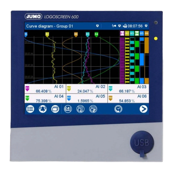
2 Description Display and control elements Touchscreen (TFT color screen) Alarm LED Technical data: The LED is lit while an alarm is pending. Chapter 6.1.7 «Screen», page 74 Power LED The screen appearance is described in The LED flashes after switching on the the «Operation»…
-
Page 19: Installation
3 Installation General information on installation WARNING! The device is not designed for use in potentially explosive areas. There is the risk of an explosion. Only deploy the device outside of potentially explosive areas. Mounting site The device is designed for installation in a panel cut-out. The front of the device and housing have different protection types (see technical data).
-
Page 20: Panel Mounting
3 Installation Panel cut-out Close mounting Distance between panel cut-outs Horizontal Vertical Minimum clearance 20 mm 20 mm Recommended distance (easier installation of fastening elements) 50 mm 50 mm Panel mounting Step Activity Insert the device into the panel cut-out from the front until the seal is flush with the panel. Insert the fastening elements into the recesses of the housing (one element on each cor- ner, see figure) and use a screwdriver to evenly clamp them against the rear side of the panel with a torque of 1.0 Nm.
-
Page 21: Handling The Front Of The Device
3 Installation CAUTION! The front of the device and case have different protection types. The protection type IP65 (front-side) is only guaranteed if the seal is flush and even. The four supplied fastening elements must all be used and distributed evenly as shown in the figure.
-
Page 22
3 Installation Dimensions Intended use The paperless recorder within the carrying case is exclusively intended for use by technically qualified personnel who are specially trained and have the relevant knowledge in the field of automation technology. Cleaning For the cleaning of the carrying case, the same instructions apply as for cleaning the front of the device. -
Page 23: Electrical Connection
4 Electrical connection Installation notes Requirements for personnel • Work on the device must only be carried out to the extent described and, like the electrical connection, only by qualified personnel. • Before plugging and unplugging connecting cables, it must be ensured that the acting per- son is electrostatically discharged (by touching grounded metallic parts, for example).
-
Page 24: Galvanic Isolation
4 Electrical connection Galvanic isolation 50 V 50 V Analog input 1 Analog output 1 50 V 50 V 50 V 50 V Analog input Analog output 3000 V 50 V Relay contact Digital input 1 Digital input 50 V Digital input 50 V…
-
Page 25: Connection Elements
4 Electrical connection Connection elements Front USB host interface (without cover) Back connection elements Connection element and assignment Connection element and assignment USB device interface Ethernet interface RS232/RS485 interface Relay Voltage supply Digital inputs 1 to 6, analog output 1 Analog input 1 Analog input 2 Analog input 3…
-
Page 26: Connection Diagram
4 Electrical connection NOTE! The front-side USB host interface is intended exclusively for connecting a USB flash drive. Any other use is not admissable. NOTE! The quality of the USB cable and the USB flash drive has an influence on the correct function of the device.
-
Page 27
4 Electrical connection Measuring probe Connection element / Assignment Terminals and connection symbol Resistance/potentiometer 7. / Analog input 1 three-wire circuit 8. / Analog input 2 9. / Analog input 3 Resistance/potentiometer 11. / Analog input 4 four-wire circuit 12. / Analog input 5 13. -
Page 28: Digital Inputs 1 To 12 (Options 1 And 2)
4 Electrical connection 4.4.2 Digital inputs 1 to 12 (options 1 and 2) Version Connection element.Terminal / Terminals and connection symbol Assignment 1 2 3 4 5 6 7 8 9 10 Digital input DC 0/24 V, 6.1 / Digital input 1 auxiliary voltage (output) DC 24 V 6.2 / Digital input 2 (50 mA, per option)
-
Page 29: Digital Inputs/Outputs 1 To 12 (Option 3)
4 Electrical connection 4.4.4 Digital inputs/outputs 1 to 12 (option 3) Version Connection element.Terminal / Terminals and connection symbol Assignment 1 2 3 4 5 6 7 8 Digital input DC 0/24 V or 14.1 / Digital input/output 1 digital output DC 0/24 V 14.2 / Digital input/output 2 (individually switchable), 14.3 / Digital input/output 3…
-
Page 30: Rs232/Rs485 Interface
4 Electrical connection 4.4.6 RS232/RS485 interface Version Connection element.Pin / Assign- Connection element ment RS232 3.2 / RxD (received data) 9-pin SUB-D socket 3.3 / TxD (transmission data) (switchable to RS485) 3.5 / GND (ground) RS485 3.3 / TxD+/RxD+ (transmission/ 9-pin SUB-D-socket received data +) (switchable to RS232)
-
Page 31: Operation
5 Operation Operating concept The device is equipped with a resistive touchscreen; the operation is menu-driven. User man- agement protects the device against unauthorized access. The different users can be assigned different privileges so that they can only access specific functions. In addition to the visualizations available per default, the setup program can be used to create individual process screens for presenting process data.
-
Page 32
5 Operation the screen), the batch logging status, and the status of data transmission via the PCC software as a text display. Icons used: Position Meaning Icon Left Data transmission via PCC software — Transmission active — Transmission not active No icon Center Batch recording… -
Page 33: Led Displays
5 Operation The area on the left contains the buttons (icons) for calling up — the main menu (left), — the alarm and event menu (center), and — the visualization menu (right). The area in the center contains buttons (icons) whose function depends on the screen cur- rently being displayed.
-
Page 34: Main Menu
5 Operation Main menu The main menu contains functions for configuring, parameterizing, and operating the device. View Menu items Scroll up Quit main menu Scroll box (current position within the menu); movable Scroll down 5.2.1 Log-In This is the menu in which users log on and off, and change their passwords. The following IDs, names, and passwords are set by default: Users Name…
-
Page 35: Configuration
5 Operation Configuration of the electronic signature: see operating manual, «Configuration – in setup pro- gram only» chapter > «Electronic signature». Example of an electronic signature: Chapter 5.8 «Electronic signature», page 63 5.2.2 Configuration This menu contains functions for configuring the device. The functions are available both on the device and in the setup program (see the «Configuration»…
-
Page 36: Calibrating The Touchscreen
5 Operation 5.2.7 Calibrating the touchscreen This menu enables you to calibrate the touchscreen (position calibration). To do so, you need to tap the center of the crosshairs shown in the corners of the screen one after another. Alarm and event menu The alarm and event menu enables you to call up the alarm list and event list.
-
Page 37: Alarm List
5 Operation 5.3.1 Alarm list The alarm list shows all pending alarms in their order of occurrence. If an alarm is no longer pending, its entry is automatically removed from the alarm list. The alarm list is rebuilt after pow- er on.
-
Page 38: Event List
5 Operation 5.3.2 Event list The event list contains event entries in chronological order. A maximum of 150 entries are stored and displayed. When new entries are added, the oldest entries are deleted. The event list is kept after power off. As with process data, events are transferred to the PC Evaluation Software PCA3000 for eval- uation.
-
Page 39
5 Operation Event list in memory display If the alarm and event menu is called up from the memory display (history) (or from the curve presentation of a completed batch), the event list is opened directly. An additional button is available here which lets you mark the time of a specific event in the memory display with the cursor position. -
Page 40: Visualization Menu (Display)
5 Operation Visualization menu (display) In the visualization menu, the view type and group that should be currently displayed on the device are selected. Up to 6 analog channels and 6 digital channels of a group can be shown on one screen. View Menu items Scroll up…
-
Page 41: Curve Diagram
5 Operation 5.4.1 Curve diagram In the curve diagram, the analog and digital signals configured for the relevant group are dis- played as analog curves or digital traces. Digital traces and channel information can be hidden in the group configuration. The diagram type (horizontal, vertical) is selected individually for each group in the configura- tion.
-
Page 42
5 Operation Memory display (history) Move time for memory values forward Time of memory values (cursor position) (later memory values) Cursor (time of numeric memory values) Zoom factor Move time for memory values back (ear- Navigation bar lier memory values) Analog value at selected time Navigation bar Quit history… -
Page 43
5 Operation Example of an electronic signature: Chapter 5.8 «Electronic signature», page 63 Horizontal diagram In the horizontal diagram, the analog curves and digital traces run from right to left. The channel information is shown on the right edge of the screen; the icons for event and alarm at the top edge of the screen. -
Page 44: Digital Diagram
5 Operation 5.4.2 Digital diagram In the digital diagram, the digital signals configured for the relevant group are displayed as dig- ital traces. The diagram type (horizontal, vertical) is selected individually for each group in the configura- tion. The following view shows the vertical diagram. Accordingly, the description also applies to the horizontal diagram.
-
Page 45: Bar Graph
5 Operation 5.4.3 Bar graph In the bar graph view, the analog signals configured for the relevant group are shown as bar graphs, and the digital signals – depending on their logical state – as colored areas or frames. The diagram type selected for the group (horizontal, vertical) is irrelevant for the bar graph view. The view is always as a column diagram (vertical) and not as a bar diagram (horizontal).
-
Page 46: Text Image
5 Operation 5.4.4 Text image The text image shows the current values for the analog signals configured for the relevant group as numbers. The digital signals – depending on their logical state – are shown as colored areas or frames. Group view Description (pointer) and short analog Digital signal with short signal descrip-…
-
Page 47
5 Operation Individual view Designation (pointer), short signal Bar graph of the analog signal description (configurable), and signal description (configurable) of the analog signal Current value of the analog signal Digital signal with short signal descrip- tion (configurable) and designation (pointer) Back to group view Displays the logical state:… -
Page 48
5 Operation Individual view with alarms Last alarm to have occurred (here: from Limit value for max. alarm (configurable) analog input 03) Current value of analog signal with color Bar graph of analog signal with color change (alarm) change (alarm) Alarm text of analog input Limit value for min. -
Page 49: Report
5 Operation 5.4.5 Report A report shows the statistical information for the relevant group. A report contains the maxi- mum, minimum, and mean values of the analog signals during the recording time (the recording period is configurable). A distinction is made between the current (on-going) report and the completed report.
-
Page 50
5 Operation Detailed view Description (pointer) and short analog Completed report signal description (configurable); report type (configurable; here: external) Time at which the max. value (or min. Current (on-going) report value) occurred Time stamp for current report: beginning Back to previous view of recording and current time Time stamp for completed report: begin- ning and end of reporting period… -
Page 51: Current Batch
5 Operation 5.4.6 Current batch This function opens the protocol for the current batch recording. Batch recording can be started and stopped (depending on the configuration). The protocol layout is defined in the batch configuration. This is where the individual lines of the protocol are defined, and the text for the left column, and content of the right column, are specified (Device: Main menu >…
-
Page 52: Completed Batch
5 Operation 5.4.7 Completed batch This function displays the report for the completed batch recording. Recorded data can be shown as a report and as a curve diagram. If necessary, the report can also display the data from current batch recording. View Open report (statistical information for Open curve presentation (analog curves…
-
Page 53
5 Operation Report for batch Description (pointer) and short analog Data (statistical information) for the signal description (configurable) completed batch recording Go to the next analog signal within the Data (statistical information) for the cur- group rent (on-going) batch recording Back to the batch report view Go to next group … -
Page 54: Process Screen
5 Operation 5.4.8 Process screen This visualization shows the individual process screens. You can use the arrow keys in the nav- igation bar to change to the next process screen. Up to 6 process screens can be created with the setup program and uploaded to the device. For a process screen to be displayed, it must be activated (configuration parameters in the set- up program;…
-
Page 55: Comment Text
5 Operation Detailed view Description (configurable) of the coun- Limit value for max. alarm (configurable) ter/integrator Details of current counter/integrator Bar graph view of the current counter/ integrator The type (configurable; here: external) decides when the status of the counter/ Start and end of the display range are integrator is stored and thus completed.
-
Page 56: Text Input Dialog
5 Operation With a device that has extra code 888 (FDA) the concerned setting is performed with the PCS software. The approach when entering a comment with authentication basically corresponds to the one when rendering an electronic signature for a completed batch (only steps 2 to 4). Example of an electronic signature: …
-
Page 57
5 Operation Text input dialog Parameters (description of the configu- Input box with current text ration parameter from the previous dia- After changing to the text input dialog, log) the current text is fully selected. Tapping on the input box displays a cursor. Tap- ping and dragging the cursor lets you select multiple characters. -
Page 58
5 Operation Keyboard mappings Each of the 30 keys in the default keyboard layout can be mapped with up to 10 characters. The Shift key toggles between the first two characters. To select more characters, you need to hold down the relevant key for longer. This displays a selection window in which you can select the desired character by tapping. -
Page 59: Flash Manager
5 Operation Flash manager The Flash manager menu automatically opens when the device is in basic status and a USB flash drive (FAT16/FAT32 file system) is plugged into the front USB port. If the device is in a menu (main menu, alarm-/event list, display), the Flash manager is opened only after leaving the menu.
-
Page 60
5 Operation plete. Device version 01: When you run the «Writing recording data to USB flash drive» function after this, only the newly-added recorded data is transferred to the USB flash drive. As of device version 02, the user can choose a time period from which the recording data is saved. -
Page 61
5 Operation Save recording data of a certain time period In the following example the recording data of a week should be saved. Select time period Determined starting time (editable) The starting time of the device is automatically determined depending on the current date (here it is: August 11, 2016), the current time (here it is 15:00:00), and the selected time period. -
Page 62: Web Server
5 Operation Web server The device includes a built-in web server which supports online visualization with the help of a web browser. The user can access the process values, various visualizations, and the device’s alarm and event list. For access, you need to enter the device’s IP address in the address line of the web browser. If needed, you can also use the DNS device name.
-
Page 63: Electronic Signature
5 Operation Electronic signature As of device version 02 and with extra code 888 (FDA), the user has the option to provide a completed batch or the recording data of a certain time period with his/her electronic signature. A logged-on user can provide his/her signature during logoff – it applies to the entire time period for which the user was signed in.
-
Page 64
5 Operation Step Activity Select your user ID (in this case: Master) The user has to select his/her ID. This step is required because someone other than the currently logged-on user can provide this signature. Enter text that describes the meaning of the signature (evaluation text) using the keyboard. Alternatively, select text from the text list (1) and, if required, edit it: The possibilities of entering a text depend on the configuration (no text available, enter text via keyboard, select text from text list, select text from text list and edit). -
Page 65
5 Operation Step Activity Enter password: Confirm process: The process can be still be aborted here. -
Page 66
5 Operation Step Activity In the protocol of a completed batch recording press the button (1) to display the provided signature: ➥ The signature (here: Master) and the meaning of the signature (here: Batch o.k.) are dis- played. -
Page 67
5 Operation Time period The electronic signature for a time period essentially differs from the signature for the complet- ed batch by requiring the time period in question to be selected. The signature applies to the time period that is displayed in the diagram at the time of the sig- nature. -
Page 68
5 Operation… -
Page 69: Annex
6 Annex Technical data 6.1.1 Analog inputs (options 1 and 2) General information Quantity 0, 3, or 6 Connector number (back of 7 to 9, 11 to 13 device) Thermocouples Description Standard Measuring range Accuracy ≤ 0.25 % Fe-CuNi «L» DIN 43710 ITPS-68 -200 to +900 °C…
-
Page 70
6 Annex RTD temperature probe Description Standard Connection Measuring range Accuracy Measur- type ing cur- rent ≤ 0.1 % 500 μA Pt50 IEC 751: 2008 ITS-90 2-/3-/4-wire -200 to +850 °C ≤ 0.1 % 500 μA Pt100 IEC 751: 2008 ITS-90 2-/3-/4-wire -200 to +850 °C… -
Page 71
6 Annex Resistance transmitter and resistor/potentiometer Description Measuring range Accuracy Measuring current 0 to 4000 Ω ≤ 0.1 % 100 μA Resistance transmitter 0 to 400 Ω ≤ 0.1 % 500 μA Resistance/potentiometer 0 to 4000 Ω ≤ 0.1 % 100 μA ≤… -
Page 72: Digital Inputs (Options 1 And 2)
6 Annex Measuring circuit monitoring The device response in the event of a fault is configurable. Measuring probe Probe break Short-circuit Polarity Thermocouple is detected is not detected is detected in certain conditions RTD temperature probe is detected is detected is not detected Resistance transmitter is detected…
-
Page 73: Digital Inputs/Outputs (Option 3)
6 Annex 6.1.3 Digital inputs/outputs (option 3) Quantity 0 or 12 Connector number (back of 14 and 15 device) Input or output Individually configurable as input or output Input Logic level «0»: < 3.5 V; logic level «1»: > 10 V Level Sampling rate 125 ms (max.
-
Page 74: Interfaces
6 Annex 6.1.6 Interfaces RS232/RS485 Quantity 1 (can be switched between RS232 and RS485) Connector type SUB-D 9-pin (socket) Baud rate 9600, 19200, 38400, 115200 Data format 8/1n, 8/1e, 8/1o Protocol Modbus RTU as master or slave; barcode scanner Application Communication with Modbus master/slave, connection of a barcode scanner External inputs Via Modbus master/slave functionality: 24 analog and 24 digital inputs, 10 batch…
-
Page 75: Electrical Data
6 Annex 6.1.8 Electrical data Voltage supply AC 110 to 240 V +10/-15 %, 48 to 63 Hz or AC/DC 20 to 30 V, 48 to 63 Hz (not in conjunction with extra code 970) Electrical safety According to DIN EN 61010-1 Overvoltage category II up to 300 V mains voltage, pollution degree 2 Protection rating I with internal isolation from SELV…
-
Page 76: Environmental Influences
6 Annex 6.1.9 Environmental influences Ambient temperature range Storage -20 to +60 °C Operation 0 to +50 °C; in conjunction with extra code 970: 0 to +40 °C Site altitude Up to 2000 m above sea level Climatic environmental conditions According to DIN EN 60721-3 with extended temperature range ≤…
-
Page 77: Change Of The Buffer Battery
6 Annex Change of the buffer battery CAUTION! The device contains a buffer battery that is used for data buffering when the device is in switched off mode or if the power fails. The life of the battery is at least 7 years. A low battery is indicated by the battery pre-alarm («Battery low»).
-
Page 78: China Rohs
6 Annex China RoHS…
-
Page 79: Barcode
6 Annex Barcode Initialize the barcode scanner The barcode scanner must be initialized once before use. Example: Step Activity Scan the „Factory Default Settings“ barcode. Scan the „RS-232 Standard“ barcode („Select RS-232 Standard“). Information and bar codes can be found in the manual of the barcode scanner used. 6.4.1 Batch control NOTE!
-
Page 80
6 Annex Reset the texts Step Activity Scan the RESET barcode. RESET The entered batch texts are reset. The default texts are shown and the first line is prepared again for the text input. The default text is defined in the configuration of the batch line (Configuration > Batch > Batch line: Default text). -
Page 81: Enter Event Texts And Process Values
6 Annex 6.4.2 Enter event texts and process values As of device version 02 an event text or process value (external text/analog/digital variables) can be entered by means of specific control characters. The text or value, which is scanned using a control character, is exclusively used as event text or process value.
-
Page 82
6 Annex Enter Boolean value in external digital variable: %Bn% = enter as Boolean value into the external digital variable n (n = 1 to 24) Example: %B1%1 %B 1 %1 The Boolean value 1 (TRUE) is entered into the external digital variable 1. The entered value is available in the digital selector. -
Page 84
JUMO GmbH & Co. KG JUMO Instrument Co. Ltd. JUMO Process Control, Inc. Street address: JUMO House 6733 Myers Road Moritz-Juchheim-Straße 1 Temple Bank, Riverway East Syracuse, NY 13057, USA 36039 Fulda, Germany Harlow, Essex CM 20 2DY, UK Phone:…
-
Page 1
JUMO LOGOSCREEN 600 Paperless Recorder with Touchscreen Brief Instructions 70652000T97Z001K000 V6.00/EN/00625186… -
Page 3: Table Of Contents
Contents Introduction …………7 Safety information .
-
Page 4
Contents 4.4.3 Analog outputs 1 and 2 (options 1 and 2) ……… . 28 4.4.4 Digital inputs/outputs 1 to 12 (option 3) . -
Page 5
Contents 6.1.6 Interfaces …………..74 6.1.7 Screen . -
Page 6
Contents… -
Page 7: Introduction
1 Introduction Safety information 1.1.1 Warning symbols DANGER! This symbol indicates that personal injury caused by electrical shock may occur if the re- spective precautionary measures are not carried out. WARNING! This symbol in connection with the signal word indicates that personal injury may occur if the respective precautionary measures are not carried out.
-
Page 8: Intended Use
1 Introduction 1.1.3 Intended use The device is designed for use as a paperless recorder in an industrial environment as speci- fied in the technical data. Other uses or uses beyond those defined are not viewed as intended uses. The device has been manufactured in compliance with applicable standards and directives as well as applicable safety regulations.
-
Page 9: Acceptance Of Goods, Storage, And Transport
1 Introduction Acceptance of goods, storage, and transport 1.2.1 Checking the delivery • Ensure that the packaging and contents are not damaged • Check that the delivery is complete using the delivery papers and the order details • Inform the supplier immediately if there is any damage •…
-
Page 10: Disposal
1 Introduction CAUTION! Electrostatic charges occur in non-ESD-protected environments. Electrostatic discharges can damage modules or components. For transport purposes, use only the ESD packaging provided. 1.2.4 Disposal Disposing of the device DISPOSAL! Devices and/or replaced parts should not be placed in the refuse bin at the end of their use- ful life as they consist of materials that can be recycled by specialist recycling plants.
-
Page 11: Identifying The Device Version
1 Introduction Identifying the device version 1.3.1 Nameplate The nameplate is affixed to the case. Contents The nameplate contains important information. This includes: Description Description on the name- Example plate Device type Type 706520/18-100-25/260 Part no. 00XXXXXX Serial number F-no. 0070033801215510006 Voltage supply DC 24 V +25/-20 %…
-
Page 12: Order Details
Not used Universal carrying case Compact Subsequent expansion is only possible in JUMO Central Services. This extra code is only available in combination with voltage supply AC 110 to 240 V. The UL approval is not applicable. Use only by technically qualified personnel who are specially trained and have the…
-
Page 13: Scope Of Delivery
1 Introduction (10) Order code Order example 706520 / / 260 , 887 , 970 1.3.3 Scope of delivery 1 paperless recorder in the ordered version 1 brief instructions 4 mounting elements 1 CD with detailed operating manual and supplementary documentation 1.3.4 Accessories Description…
-
Page 14: Content Of The Technical Documentation
1 Introduction Content of the technical documentation The documentation for this device is addressed to equipment manufacturers (OEMs) and users with appropriate technical expertise; it consists of the following documents. 1.4.1 Device documentation in printed form 70652000T97… Brief instructions A hard copy of the brief instructions is part of the scope of delivery of the device. The brief instructions describe the installation, the electrical connection and the operation of the device.
-
Page 15: Device Version
1 Introduction B 709701.0 PC Evaluation Software PCA3000 The operating manual describes the operation and the features of the PC Evaluation Software. The PC Evaluation Software helps to visualize and evaluate the recorded registration data (measurement data, batch data, messages, etc.). B 709702.0 PCA Communications Software PCC The operating manual describes the operation and the features of the PCA Communication…
-
Page 16: Functions Of The Device Version 02
1 Introduction Functions of the device version 02 New functions The following new functions were implemented in device version 02. • Extra code 887 «Manipulation detection with digital certificate»: manipulation detection for the recording data by using a certificate (during saving and transfer) •…
-
Page 17: Description
There are different versions of the JUMO LOGOSCREEN 600 available for process data re- cording. These range from the device version without measuring input in which up to 24 pro-…
-
Page 18: Display And Control Elements
2 Description Display and control elements Touchscreen (TFT color screen) Alarm LED Technical data: The LED is lit while an alarm is pending. Chapter 6.1.7 «Screen», page 74 Power LED The screen appearance is described in The LED flashes after switching on the the «Operation»…
-
Page 19: Installation
3 Installation General information on installation WARNING! The device is not designed for use in potentially explosive areas. There is the risk of an explosion. Only deploy the device outside of potentially explosive areas. Mounting site The device is designed for installation in a panel cut-out. The front of the device and housing have different protection types (see technical data).
-
Page 20: Panel Mounting
3 Installation Panel cut-out Close mounting Distance between panel cut-outs Horizontal Vertical Minimum clearance 20 mm 20 mm Recommended distance (easier installation of fastening elements) 50 mm 50 mm Panel mounting Step Activity Insert the device into the panel cut-out from the front until the seal is flush with the panel. Insert the fastening elements into the recesses of the housing (one element on each cor- ner, see figure) and use a screwdriver to evenly clamp them against the rear side of the panel with a torque of 1.0 Nm.
-
Page 21: Handling The Front Of The Device
3 Installation CAUTION! The front of the device and case have different protection types. The protection type IP65 (front-side) is only guaranteed if the seal is flush and even. The four supplied fastening elements must all be used and distributed evenly as shown in the figure.
-
Page 22
3 Installation Dimensions Intended use The paperless recorder within the carrying case is exclusively intended for use by technically qualified personnel who are specially trained and have the relevant knowledge in the field of automation technology. Cleaning For the cleaning of the carrying case, the same instructions apply as for cleaning the front of the device. -
Page 23: Electrical Connection
4 Electrical connection Installation notes Requirements for personnel • Work on the device must only be carried out to the extent described and, like the electrical connection, only by qualified personnel. • Before plugging and unplugging connecting cables, it must be ensured that the acting per- son is electrostatically discharged (by touching grounded metallic parts, for example).
-
Page 24: Galvanic Isolation
4 Electrical connection Galvanic isolation 50 V 50 V Analog input 1 Analog output 1 50 V 50 V 50 V 50 V Analog input Analog output 3000 V 50 V Relay contact Digital input 1 Digital input 50 V Digital input 50 V…
-
Page 25: Connection Elements
4 Electrical connection Connection elements Front USB host interface (without cover) Back connection elements Connection element and assignment Connection element and assignment USB device interface Ethernet interface RS232/RS485 interface Relay Voltage supply Digital inputs 1 to 6, analog output 1 Analog input 1 Analog input 2 Analog input 3…
-
Page 26: Connection Diagram
4 Electrical connection NOTE! The front-side USB host interface is intended exclusively for connecting a USB flash drive. Any other use is not admissable. NOTE! The quality of the USB cable and the USB flash drive has an influence on the correct function of the device.
-
Page 27
4 Electrical connection Measuring probe Connection element / Assignment Terminals and connection symbol Resistance/potentiometer 7. / Analog input 1 three-wire circuit 8. / Analog input 2 9. / Analog input 3 Resistance/potentiometer 11. / Analog input 4 four-wire circuit 12. / Analog input 5 13. -
Page 28: Digital Inputs 1 To 12 (Options 1 And 2)
4 Electrical connection 4.4.2 Digital inputs 1 to 12 (options 1 and 2) Version Connection element.Terminal / Terminals and connection symbol Assignment 1 2 3 4 5 6 7 8 9 10 Digital input DC 0/24 V, 6.1 / Digital input 1 auxiliary voltage (output) DC 24 V 6.2 / Digital input 2 (50 mA, per option)
-
Page 29: Digital Inputs/Outputs 1 To 12 (Option 3)
4 Electrical connection 4.4.4 Digital inputs/outputs 1 to 12 (option 3) Version Connection element.Terminal / Terminals and connection symbol Assignment 1 2 3 4 5 6 7 8 Digital input DC 0/24 V or 14.1 / Digital input/output 1 digital output DC 0/24 V 14.2 / Digital input/output 2 (individually switchable), 14.3 / Digital input/output 3…
-
Page 30: Rs232/Rs485 Interface
4 Electrical connection 4.4.6 RS232/RS485 interface Version Connection element.Pin / Assign- Connection element ment RS232 3.2 / RxD (received data) 9-pin SUB-D socket 3.3 / TxD (transmission data) (switchable to RS485) 3.5 / GND (ground) RS485 3.3 / TxD+/RxD+ (transmission/ 9-pin SUB-D-socket received data +) (switchable to RS232)
-
Page 31: Operation
5 Operation Operating concept The device is equipped with a resistive touchscreen; the operation is menu-driven. User man- agement protects the device against unauthorized access. The different users can be assigned different privileges so that they can only access specific functions. In addition to the visualizations available per default, the setup program can be used to create individual process screens for presenting process data.
-
Page 32
5 Operation the screen), the batch logging status, and the status of data transmission via the PCC software as a text display. Icons used: Position Meaning Icon Left Data transmission via PCC software — Transmission active — Transmission not active No icon Center Batch recording… -
Page 33: Led Displays
5 Operation The area on the left contains the buttons (icons) for calling up — the main menu (left), — the alarm and event menu (center), and — the visualization menu (right). The area in the center contains buttons (icons) whose function depends on the screen cur- rently being displayed.
-
Page 34: Main Menu
5 Operation Main menu The main menu contains functions for configuring, parameterizing, and operating the device. View Menu items Scroll up Quit main menu Scroll box (current position within the menu); movable Scroll down 5.2.1 Log-In This is the menu in which users log on and off, and change their passwords. The following IDs, names, and passwords are set by default: Users Name…
-
Page 35: Configuration
5 Operation Configuration of the electronic signature: see operating manual, «Configuration – in setup pro- gram only» chapter > «Electronic signature». Example of an electronic signature: Chapter 5.8 «Electronic signature», page 63 5.2.2 Configuration This menu contains functions for configuring the device. The functions are available both on the device and in the setup program (see the «Configuration»…
-
Page 36: Calibrating The Touchscreen
5 Operation 5.2.7 Calibrating the touchscreen This menu enables you to calibrate the touchscreen (position calibration). To do so, you need to tap the center of the crosshairs shown in the corners of the screen one after another. Alarm and event menu The alarm and event menu enables you to call up the alarm list and event list.
-
Page 37: Alarm List
5 Operation 5.3.1 Alarm list The alarm list shows all pending alarms in their order of occurrence. If an alarm is no longer pending, its entry is automatically removed from the alarm list. The alarm list is rebuilt after pow- er on.
-
Page 38: Event List
5 Operation 5.3.2 Event list The event list contains event entries in chronological order. A maximum of 150 entries are stored and displayed. When new entries are added, the oldest entries are deleted. The event list is kept after power off. As with process data, events are transferred to the PC Evaluation Software PCA3000 for eval- uation.
-
Page 39
5 Operation Event list in memory display If the alarm and event menu is called up from the memory display (history) (or from the curve presentation of a completed batch), the event list is opened directly. An additional button is available here which lets you mark the time of a specific event in the memory display with the cursor position. -
Page 40: Visualization Menu (Display)
5 Operation Visualization menu (display) In the visualization menu, the view type and group that should be currently displayed on the device are selected. Up to 6 analog channels and 6 digital channels of a group can be shown on one screen. View Menu items Scroll up…
-
Page 41: Curve Diagram
5 Operation 5.4.1 Curve diagram In the curve diagram, the analog and digital signals configured for the relevant group are dis- played as analog curves or digital traces. Digital traces and channel information can be hidden in the group configuration. The diagram type (horizontal, vertical) is selected individually for each group in the configura- tion.
-
Page 42
5 Operation Memory display (history) Move time for memory values forward Time of memory values (cursor position) (later memory values) Cursor (time of numeric memory values) Zoom factor Move time for memory values back (ear- Navigation bar lier memory values) Analog value at selected time Navigation bar Quit history… -
Page 43
5 Operation Example of an electronic signature: Chapter 5.8 «Electronic signature», page 63 Horizontal diagram In the horizontal diagram, the analog curves and digital traces run from right to left. The channel information is shown on the right edge of the screen; the icons for event and alarm at the top edge of the screen. -
Page 44: Digital Diagram
5 Operation 5.4.2 Digital diagram In the digital diagram, the digital signals configured for the relevant group are displayed as dig- ital traces. The diagram type (horizontal, vertical) is selected individually for each group in the configura- tion. The following view shows the vertical diagram. Accordingly, the description also applies to the horizontal diagram.
-
Page 45: Bar Graph
5 Operation 5.4.3 Bar graph In the bar graph view, the analog signals configured for the relevant group are shown as bar graphs, and the digital signals – depending on their logical state – as colored areas or frames. The diagram type selected for the group (horizontal, vertical) is irrelevant for the bar graph view. The view is always as a column diagram (vertical) and not as a bar diagram (horizontal).
-
Page 46: Text Image
5 Operation 5.4.4 Text image The text image shows the current values for the analog signals configured for the relevant group as numbers. The digital signals – depending on their logical state – are shown as colored areas or frames. Group view Description (pointer) and short analog Digital signal with short signal descrip-…
-
Page 47
5 Operation Individual view Designation (pointer), short signal Bar graph of the analog signal description (configurable), and signal description (configurable) of the analog signal Current value of the analog signal Digital signal with short signal descrip- tion (configurable) and designation (pointer) Back to group view Displays the logical state:… -
Page 48
5 Operation Individual view with alarms Last alarm to have occurred (here: from Limit value for max. alarm (configurable) analog input 03) Current value of analog signal with color Bar graph of analog signal with color change (alarm) change (alarm) Alarm text of analog input Limit value for min. -
Page 49: Report
5 Operation 5.4.5 Report A report shows the statistical information for the relevant group. A report contains the maxi- mum, minimum, and mean values of the analog signals during the recording time (the recording period is configurable). A distinction is made between the current (on-going) report and the completed report.
-
Page 50
5 Operation Detailed view Description (pointer) and short analog Completed report signal description (configurable); report type (configurable; here: external) Time at which the max. value (or min. Current (on-going) report value) occurred Time stamp for current report: beginning Back to previous view of recording and current time Time stamp for completed report: begin- ning and end of reporting period… -
Page 51: Current Batch
5 Operation 5.4.6 Current batch This function opens the protocol for the current batch recording. Batch recording can be started and stopped (depending on the configuration). The protocol layout is defined in the batch configuration. This is where the individual lines of the protocol are defined, and the text for the left column, and content of the right column, are specified (Device: Main menu >…
-
Page 52: Completed Batch
5 Operation 5.4.7 Completed batch This function displays the report for the completed batch recording. Recorded data can be shown as a report and as a curve diagram. If necessary, the report can also display the data from current batch recording. View Open report (statistical information for Open curve presentation (analog curves…
-
Page 53
5 Operation Report for batch Description (pointer) and short analog Data (statistical information) for the signal description (configurable) completed batch recording Go to the next analog signal within the Data (statistical information) for the cur- group rent (on-going) batch recording Back to the batch report view Go to next group … -
Page 54: Process Screen
5 Operation 5.4.8 Process screen This visualization shows the individual process screens. You can use the arrow keys in the nav- igation bar to change to the next process screen. Up to 6 process screens can be created with the setup program and uploaded to the device. For a process screen to be displayed, it must be activated (configuration parameters in the set- up program;…
-
Page 55: Comment Text
5 Operation Detailed view Description (configurable) of the coun- Limit value for max. alarm (configurable) ter/integrator Details of current counter/integrator Bar graph view of the current counter/ integrator The type (configurable; here: external) decides when the status of the counter/ Start and end of the display range are integrator is stored and thus completed.
-
Page 56: Text Input Dialog
5 Operation With a device that has extra code 888 (FDA) the concerned setting is performed with the PCS software. The approach when entering a comment with authentication basically corresponds to the one when rendering an electronic signature for a completed batch (only steps 2 to 4). Example of an electronic signature: …
-
Page 57
5 Operation Text input dialog Parameters (description of the configu- Input box with current text ration parameter from the previous dia- After changing to the text input dialog, log) the current text is fully selected. Tapping on the input box displays a cursor. Tap- ping and dragging the cursor lets you select multiple characters. -
Page 58
5 Operation Keyboard mappings Each of the 30 keys in the default keyboard layout can be mapped with up to 10 characters. The Shift key toggles between the first two characters. To select more characters, you need to hold down the relevant key for longer. This displays a selection window in which you can select the desired character by tapping. -
Page 59: Flash Manager
5 Operation Flash manager The Flash manager menu automatically opens when the device is in basic status and a USB flash drive (FAT16/FAT32 file system) is plugged into the front USB port. If the device is in a menu (main menu, alarm-/event list, display), the Flash manager is opened only after leaving the menu.
-
Page 60
5 Operation plete. Device version 01: When you run the «Writing recording data to USB flash drive» function after this, only the newly-added recorded data is transferred to the USB flash drive. As of device version 02, the user can choose a time period from which the recording data is saved. -
Page 61
5 Operation Save recording data of a certain time period In the following example the recording data of a week should be saved. Select time period Determined starting time (editable) The starting time of the device is automatically determined depending on the current date (here it is: August 11, 2016), the current time (here it is 15:00:00), and the selected time period. -
Page 62: Web Server
5 Operation Web server The device includes a built-in web server which supports online visualization with the help of a web browser. The user can access the process values, various visualizations, and the device’s alarm and event list. For access, you need to enter the device’s IP address in the address line of the web browser. If needed, you can also use the DNS device name.
-
Page 63: Electronic Signature
5 Operation Electronic signature As of device version 02 and with extra code 888 (FDA), the user has the option to provide a completed batch or the recording data of a certain time period with his/her electronic signature. A logged-on user can provide his/her signature during logoff – it applies to the entire time period for which the user was signed in.
-
Page 64
5 Operation Step Activity Select your user ID (in this case: Master) The user has to select his/her ID. This step is required because someone other than the currently logged-on user can provide this signature. Enter text that describes the meaning of the signature (evaluation text) using the keyboard. Alternatively, select text from the text list (1) and, if required, edit it: The possibilities of entering a text depend on the configuration (no text available, enter text via keyboard, select text from text list, select text from text list and edit). -
Page 65
5 Operation Step Activity Enter password: Confirm process: The process can be still be aborted here. -
Page 66
5 Operation Step Activity In the protocol of a completed batch recording press the button (1) to display the provided signature: ➥ The signature (here: Master) and the meaning of the signature (here: Batch o.k.) are dis- played. -
Page 67
5 Operation Time period The electronic signature for a time period essentially differs from the signature for the complet- ed batch by requiring the time period in question to be selected. The signature applies to the time period that is displayed in the diagram at the time of the sig- nature. -
Page 68
5 Operation… -
Page 69: Annex
6 Annex Technical data 6.1.1 Analog inputs (options 1 and 2) General information Quantity 0, 3, or 6 Connector number (back of 7 to 9, 11 to 13 device) Thermocouples Description Standard Measuring range Accuracy ≤ 0.25 % Fe-CuNi «L» DIN 43710 ITPS-68 -200 to +900 °C…
-
Page 70
6 Annex RTD temperature probe Description Standard Connection Measuring range Accuracy Measur- type ing cur- rent ≤ 0.1 % 500 μA Pt50 IEC 751: 2008 ITS-90 2-/3-/4-wire -200 to +850 °C ≤ 0.1 % 500 μA Pt100 IEC 751: 2008 ITS-90 2-/3-/4-wire -200 to +850 °C… -
Page 71
6 Annex Resistance transmitter and resistor/potentiometer Description Measuring range Accuracy Measuring current 0 to 4000 Ω ≤ 0.1 % 100 μA Resistance transmitter 0 to 400 Ω ≤ 0.1 % 500 μA Resistance/potentiometer 0 to 4000 Ω ≤ 0.1 % 100 μA ≤… -
Page 72: Digital Inputs (Options 1 And 2)
6 Annex Measuring circuit monitoring The device response in the event of a fault is configurable. Measuring probe Probe break Short-circuit Polarity Thermocouple is detected is not detected is detected in certain conditions RTD temperature probe is detected is detected is not detected Resistance transmitter is detected…
-
Page 73: Digital Inputs/Outputs (Option 3)
6 Annex 6.1.3 Digital inputs/outputs (option 3) Quantity 0 or 12 Connector number (back of 14 and 15 device) Input or output Individually configurable as input or output Input Logic level «0»: < 3.5 V; logic level «1»: > 10 V Level Sampling rate 125 ms (max.
-
Page 74: Interfaces
6 Annex 6.1.6 Interfaces RS232/RS485 Quantity 1 (can be switched between RS232 and RS485) Connector type SUB-D 9-pin (socket) Baud rate 9600, 19200, 38400, 115200 Data format 8/1n, 8/1e, 8/1o Protocol Modbus RTU as master or slave; barcode scanner Application Communication with Modbus master/slave, connection of a barcode scanner External inputs Via Modbus master/slave functionality: 24 analog and 24 digital inputs, 10 batch…
-
Page 75: Electrical Data
6 Annex 6.1.8 Electrical data Voltage supply AC 110 to 240 V +10/-15 %, 48 to 63 Hz or AC/DC 20 to 30 V, 48 to 63 Hz (not in conjunction with extra code 970) Electrical safety According to DIN EN 61010-1 Overvoltage category II up to 300 V mains voltage, pollution degree 2 Protection rating I with internal isolation from SELV…
-
Page 76: Environmental Influences
6 Annex 6.1.9 Environmental influences Ambient temperature range Storage -20 to +60 °C Operation 0 to +50 °C; in conjunction with extra code 970: 0 to +40 °C Site altitude Up to 2000 m above sea level Climatic environmental conditions According to DIN EN 60721-3 with extended temperature range ≤…
-
Page 77: Change Of The Buffer Battery
6 Annex Change of the buffer battery CAUTION! The device contains a buffer battery that is used for data buffering when the device is in switched off mode or if the power fails. The life of the battery is at least 7 years. A low battery is indicated by the battery pre-alarm («Battery low»).
-
Page 78: China Rohs
6 Annex China RoHS…
-
Page 79: Barcode
6 Annex Barcode Initialize the barcode scanner The barcode scanner must be initialized once before use. Example: Step Activity Scan the „Factory Default Settings“ barcode. Scan the „RS-232 Standard“ barcode („Select RS-232 Standard“). Information and bar codes can be found in the manual of the barcode scanner used. 6.4.1 Batch control NOTE!
-
Page 80
6 Annex Reset the texts Step Activity Scan the RESET barcode. RESET The entered batch texts are reset. The default texts are shown and the first line is prepared again for the text input. The default text is defined in the configuration of the batch line (Configuration > Batch > Batch line: Default text). -
Page 81: Enter Event Texts And Process Values
6 Annex 6.4.2 Enter event texts and process values As of device version 02 an event text or process value (external text/analog/digital variables) can be entered by means of specific control characters. The text or value, which is scanned using a control character, is exclusively used as event text or process value.
-
Page 82
6 Annex Enter Boolean value in external digital variable: %Bn% = enter as Boolean value into the external digital variable n (n = 1 to 24) Example: %B1%1 %B 1 %1 The Boolean value 1 (TRUE) is entered into the external digital variable 1. The entered value is available in the digital selector. -
Page 84
JUMO GmbH & Co. KG JUMO Instrument Co. Ltd. JUMO Process Control, Inc. Street address: JUMO House 6733 Myers Road Moritz-Juchheim-Straße 1 Temple Bank, Riverway East Syracuse, NY 13057, USA 36039 Fulda, Germany Harlow, Essex CM 20 2DY, UK Phone:…

JUMO LOGOSCREEN 600
Paperless Recorder with Touchscreen
Operating Manual
70652000T90Z001K000
V6.00/EN/00625183
Contents
1
Introduction . . . . . . . . . . . . . . . . . . . . . . . . . . . . . . . . . . . . . . . . . . . . . . . . . . . . . .9
1.1
1.1.1
1.1.2
1.1.3
1.1.4
1.2
1.2.1
1.2.2
1.2.3
1.2.4
1.3
1.3.1
1.3.2
1.3.3
1.3.4
1.4
1.4.1
1.4.2
1.4.3
1.5
1.6
Safety information . . . . . . . . . . . . . . . . . . . . . . . . . . . . . . . . . . . . . . . . . . . . . . . . . . . . . . . . . . . . . 9
Warning symbols . . . . . . . . . . . . . . . . . . . . . . . . . . . . . . . . . . . . . . . . . . . . . . . . . . . . . . . . . . . . . . 9
Note symbols . . . . . . . . . . . . . . . . . . . . . . . . . . . . . . . . . . . . . . . . . . . . . . . . . . . . . . . . . . . . . . . . . 9
Intended use . . . . . . . . . . . . . . . . . . . . . . . . . . . . . . . . . . . . . . . . . . . . . . . . . . . . . . . . . . . . . . . . 10
Qualification of personnel . . . . . . . . . . . . . . . . . . . . . . . . . . . . . . . . . . . . . . . . . . . . . . . . . . . . . . 10
Acceptance of goods, storage, and transport . . . . . . . . . . . . . . . . . . . . . . . . . . . . . . . . . . . . . . . 11
Checking the delivery . . . . . . . . . . . . . . . . . . . . . . . . . . . . . . . . . . . . . . . . . . . . . . . . . . . . . . . . . 11
Notes on storage and transport . . . . . . . . . . . . . . . . . . . . . . . . . . . . . . . . . . . . . . . . . . . . . . . . . . 11
Returning goods . . . . . . . . . . . . . . . . . . . . . . . . . . . . . . . . . . . . . . . . . . . . . . . . . . . . . . . . . . . . . 11
Disposal . . . . . . . . . . . . . . . . . . . . . . . . . . . . . . . . . . . . . . . . . . . . . . . . . . . . . . . . . . . . . . . . . . . . 12
Identifying the device version . . . . . . . . . . . . . . . . . . . . . . . . . . . . . . . . . . . . . . . . . . . . . . . . . . . 13
Nameplate . . . . . . . . . . . . . . . . . . . . . . . . . . . . . . . . . . . . . . . . . . . . . . . . . . . . . . . . . . . . . . . . . . 13
Order details . . . . . . . . . . . . . . . . . . . . . . . . . . . . . . . . . . . . . . . . . . . . . . . . . . . . . . . . . . . . . . . . 14
Scope of delivery . . . . . . . . . . . . . . . . . . . . . . . . . . . . . . . . . . . . . . . . . . . . . . . . . . . . . . . . . . . . . 15
Accessories . . . . . . . . . . . . . . . . . . . . . . . . . . . . . . . . . . . . . . . . . . . . . . . . . . . . . . . . . . . . . . . . . 15
Content of the technical documentation . . . . . . . . . . . . . . . . . . . . . . . . . . . . . . . . . . . . . . . . . . . 16
Device documentation in printed form . . . . . . . . . . . . . . . . . . . . . . . . . . . . . . . . . . . . . . . . . . . . . 16
Device documentation in the form of PDF files . . . . . . . . . . . . . . . . . . . . . . . . . . . . . . . . . . . . . . 16
Documentation for optional software . . . . . . . . . . . . . . . . . . . . . . . . . . . . . . . . . . . . . . . . . . . . . . 16
Device version . . . . . . . . . . . . . . . . . . . . . . . . . . . . . . . . . . . . . . . . . . . . . . . . . . . . . . . . . . . . . . . 17
Functions of the device version 02 . . . . . . . . . . . . . . . . . . . . . . . . . . . . . . . . . . . . . . . . . . . . . . . 18
2
Description . . . . . . . . . . . . . . . . . . . . . . . . . . . . . . . . . . . . . . . . . . . . . . . . . . . . . .19
2.1
2.2
2.3
2.4
Brief description . . . . . . . . . . . . . . . . . . . . . . . . . . . . . . . . . . . . . . . . . . . . . . . . . . . . . . . . . . . . . .
Block diagram . . . . . . . . . . . . . . . . . . . . . . . . . . . . . . . . . . . . . . . . . . . . . . . . . . . . . . . . . . . . . . .
Display and control elements . . . . . . . . . . . . . . . . . . . . . . . . . . . . . . . . . . . . . . . . . . . . . . . . . . .
Connection elements . . . . . . . . . . . . . . . . . . . . . . . . . . . . . . . . . . . . . . . . . . . . . . . . . . . . . . . . . .
3
Installation . . . . . . . . . . . . . . . . . . . . . . . . . . . . . . . . . . . . . . . . . . . . . . . . . . . . . .21
3.1
3.2
3.3
3.4
3.5
General information on installation . . . . . . . . . . . . . . . . . . . . . . . . . . . . . . . . . . . . . . . . . . . . . . .
Dimensions . . . . . . . . . . . . . . . . . . . . . . . . . . . . . . . . . . . . . . . . . . . . . . . . . . . . . . . . . . . . . . . . .
Panel mounting . . . . . . . . . . . . . . . . . . . . . . . . . . . . . . . . . . . . . . . . . . . . . . . . . . . . . . . . . . . . . .
Handling the front of the device . . . . . . . . . . . . . . . . . . . . . . . . . . . . . . . . . . . . . . . . . . . . . . . . . .
Universal carrying case Compact (extra code 970) . . . . . . . . . . . . . . . . . . . . . . . . . . . . . . . . . .
4
Electrical connection . . . . . . . . . . . . . . . . . . . . . . . . . . . . . . . . . . . . . . . . . . . . .25
4.1
4.2
4.3
4.4
4.4.1
4.4.2
Installation notes . . . . . . . . . . . . . . . . . . . . . . . . . . . . . . . . . . . . . . . . . . . . . . . . . . . . . . . . . . . . .
Galvanic isolation . . . . . . . . . . . . . . . . . . . . . . . . . . . . . . . . . . . . . . . . . . . . . . . . . . . . . . . . . . . .
Connection elements . . . . . . . . . . . . . . . . . . . . . . . . . . . . . . . . . . . . . . . . . . . . . . . . . . . . . . . . . .
Connection diagram . . . . . . . . . . . . . . . . . . . . . . . . . . . . . . . . . . . . . . . . . . . . . . . . . . . . . . . . . .
Analog inputs 1 to 6 (options 1 and 2) . . . . . . . . . . . . . . . . . . . . . . . . . . . . . . . . . . . . . . . . . . . . .
Digital inputs 1 to 12 (options 1 and 2) . . . . . . . . . . . . . . . . . . . . . . . . . . . . . . . . . . . . . . . . . . . .
19
19
20
20
21
21
22
23
23
25
26
27
28
28
30
3
Contents
4.4.3
4.4.4
4.4.5
4.4.6
4.4.7
Analog outputs 1 and 2 (options 1 and 2) . . . . . . . . . . . . . . . . . . . . . . . . . . . . . . . . . . . . . . . . . .
Digital inputs/outputs 1 to 12 (option 3) . . . . . . . . . . . . . . . . . . . . . . . . . . . . . . . . . . . . . . . . . . . .
Relay . . . . . . . . . . . . . . . . . . . . . . . . . . . . . . . . . . . . . . . . . . . . . . . . . . . . . . . . . . . . . . . . . . . . . .
RS232/RS485 interface . . . . . . . . . . . . . . . . . . . . . . . . . . . . . . . . . . . . . . . . . . . . . . . . . . . . . . . .
Voltage supply . . . . . . . . . . . . . . . . . . . . . . . . . . . . . . . . . . . . . . . . . . . . . . . . . . . . . . . . . . . . . . .
5
Operation . . . . . . . . . . . . . . . . . . . . . . . . . . . . . . . . . . . . . . . . . . . . . . . . . . . . . . .33
5.1
5.1.1
5.1.2
5.2
5.2.1
5.2.2
5.2.3
5.2.4
5.2.5
5.2.6
5.2.7
5.3
5.3.1
5.3.2
5.4
5.4.1
5.4.2
5.4.3
5.4.4
5.4.5
5.4.6
5.4.7
5.4.8
5.4.9
5.4.10
5.5
5.6
5.7
5.8
Operating concept . . . . . . . . . . . . . . . . . . . . . . . . . . . . . . . . . . . . . . . . . . . . . . . . . . . . . . . . . . . .
Touchscreen . . . . . . . . . . . . . . . . . . . . . . . . . . . . . . . . . . . . . . . . . . . . . . . . . . . . . . . . . . . . . . . .
LED displays . . . . . . . . . . . . . . . . . . . . . . . . . . . . . . . . . . . . . . . . . . . . . . . . . . . . . . . . . . . . . . . .
Main menu . . . . . . . . . . . . . . . . . . . . . . . . . . . . . . . . . . . . . . . . . . . . . . . . . . . . . . . . . . . . . . . . . .
Log-In . . . . . . . . . . . . . . . . . . . . . . . . . . . . . . . . . . . . . . . . . . . . . . . . . . . . . . . . . . . . . . . . . . . . .
Configuration . . . . . . . . . . . . . . . . . . . . . . . . . . . . . . . . . . . . . . . . . . . . . . . . . . . . . . . . . . . . . . . .
Parameterization . . . . . . . . . . . . . . . . . . . . . . . . . . . . . . . . . . . . . . . . . . . . . . . . . . . . . . . . . . . . .
Device info . . . . . . . . . . . . . . . . . . . . . . . . . . . . . . . . . . . . . . . . . . . . . . . . . . . . . . . . . . . . . . . . . .
Audit trail list . . . . . . . . . . . . . . . . . . . . . . . . . . . . . . . . . . . . . . . . . . . . . . . . . . . . . . . . . . . . . . . .
Service . . . . . . . . . . . . . . . . . . . . . . . . . . . . . . . . . . . . . . . . . . . . . . . . . . . . . . . . . . . . . . . . . . . .
Calibrating the touchscreen . . . . . . . . . . . . . . . . . . . . . . . . . . . . . . . . . . . . . . . . . . . . . . . . . . . . .
Alarm and event menu . . . . . . . . . . . . . . . . . . . . . . . . . . . . . . . . . . . . . . . . . . . . . . . . . . . . . . . .
Alarm list . . . . . . . . . . . . . . . . . . . . . . . . . . . . . . . . . . . . . . . . . . . . . . . . . . . . . . . . . . . . . . . . . . .
Event list . . . . . . . . . . . . . . . . . . . . . . . . . . . . . . . . . . . . . . . . . . . . . . . . . . . . . . . . . . . . . . . . . . .
Visualization menu (display) . . . . . . . . . . . . . . . . . . . . . . . . . . . . . . . . . . . . . . . . . . . . . . . . . . . .
Curve diagram . . . . . . . . . . . . . . . . . . . . . . . . . . . . . . . . . . . . . . . . . . . . . . . . . . . . . . . . . . . . . . .
Digital diagram . . . . . . . . . . . . . . . . . . . . . . . . . . . . . . . . . . . . . . . . . . . . . . . . . . . . . . . . . . . . . .
Bar graph . . . . . . . . . . . . . . . . . . . . . . . . . . . . . . . . . . . . . . . . . . . . . . . . . . . . . . . . . . . . . . . . . . .
Text image . . . . . . . . . . . . . . . . . . . . . . . . . . . . . . . . . . . . . . . . . . . . . . . . . . . . . . . . . . . . . . . . . .
Report . . . . . . . . . . . . . . . . . . . . . . . . . . . . . . . . . . . . . . . . . . . . . . . . . . . . . . . . . . . . . . . . . . . . .
Current batch . . . . . . . . . . . . . . . . . . . . . . . . . . . . . . . . . . . . . . . . . . . . . . . . . . . . . . . . . . . . . . . .
Completed batch . . . . . . . . . . . . . . . . . . . . . . . . . . . . . . . . . . . . . . . . . . . . . . . . . . . . . . . . . . . . .
Process screen . . . . . . . . . . . . . . . . . . . . . . . . . . . . . . . . . . . . . . . . . . . . . . . . . . . . . . . . . . . . . .
Counter/Integrator . . . . . . . . . . . . . . . . . . . . . . . . . . . . . . . . . . . . . . . . . . . . . . . . . . . . . . . . . . . .
Comment text . . . . . . . . . . . . . . . . . . . . . . . . . . . . . . . . . . . . . . . . . . . . . . . . . . . . . . . . . . . . . . .
Text input dialog . . . . . . . . . . . . . . . . . . . . . . . . . . . . . . . . . . . . . . . . . . . . . . . . . . . . . . . . . . . . .
Flash manager . . . . . . . . . . . . . . . . . . . . . . . . . . . . . . . . . . . . . . . . . . . . . . . . . . . . . . . . . . . . . .
Web server . . . . . . . . . . . . . . . . . . . . . . . . . . . . . . . . . . . . . . . . . . . . . . . . . . . . . . . . . . . . . . . . .
Electronic signature . . . . . . . . . . . . . . . . . . . . . . . . . . . . . . . . . . . . . . . . . . . . . . . . . . . . . . . . . . .
6
Setup program . . . . . . . . . . . . . . . . . . . . . . . . . . . . . . . . . . . . . . . . . . . . . . . . . . .73
6.1
6.1.1
6.1.2
6.1.3
6.2
6.3
Installation . . . . . . . . . . . . . . . . . . . . . . . . . . . . . . . . . . . . . . . . . . . . . . . . . . . . . . . . . . . . . . . . . .
Hardware and software requirements . . . . . . . . . . . . . . . . . . . . . . . . . . . . . . . . . . . . . . . . . . . . .
Installing and starting the program . . . . . . . . . . . . . . . . . . . . . . . . . . . . . . . . . . . . . . . . . . . . . . .
Logon and rights . . . . . . . . . . . . . . . . . . . . . . . . . . . . . . . . . . . . . . . . . . . . . . . . . . . . . . . . . . . . .
User interface . . . . . . . . . . . . . . . . . . . . . . . . . . . . . . . . . . . . . . . . . . . . . . . . . . . . . . . . . . . . . . .
Menu bar functions . . . . . . . . . . . . . . . . . . . . . . . . . . . . . . . . . . . . . . . . . . . . . . . . . . . . . . . . . . .
4
30
31
31
32
32
33
33
35
36
36
37
37
37
37
37
38
39
40
41
43
44
47
48
49
52
54
55
57
57
58
59
62
65
67
73
73
73
74
76
79
Contents
6.3.1
6.3.2
6.3.3
6.3.4
6.3.5
6.3.6
6.3.7
6.4
6.4.1
6.4.2
6.4.3
6.4.4
File . . . . . . . . . . . . . . . . . . . . . . . . . . . . . . . . . . . . . . . . . . . . . . . . . . . . . . . . . . . . . . . . . . . . . . . .
Edit . . . . . . . . . . . . . . . . . . . . . . . . . . . . . . . . . . . . . . . . . . . . . . . . . . . . . . . . . . . . . . . . . . . . . . .
Data transfer . . . . . . . . . . . . . . . . . . . . . . . . . . . . . . . . . . . . . . . . . . . . . . . . . . . . . . . . . . . . . . . .
Extras . . . . . . . . . . . . . . . . . . . . . . . . . . . . . . . . . . . . . . . . . . . . . . . . . . . . . . . . . . . . . . . . . . . . .
View . . . . . . . . . . . . . . . . . . . . . . . . . . . . . . . . . . . . . . . . . . . . . . . . . . . . . . . . . . . . . . . . . . . . . . .
Window . . . . . . . . . . . . . . . . . . . . . . . . . . . . . . . . . . . . . . . . . . . . . . . . . . . . . . . . . . . . . . . . . . . .
Info . . . . . . . . . . . . . . . . . . . . . . . . . . . . . . . . . . . . . . . . . . . . . . . . . . . . . . . . . . . . . . . . . . . . . . .
Setup file . . . . . . . . . . . . . . . . . . . . . . . . . . . . . . . . . . . . . . . . . . . . . . . . . . . . . . . . . . . . . . . . . . .
Views and functions . . . . . . . . . . . . . . . . . . . . . . . . . . . . . . . . . . . . . . . . . . . . . . . . . . . . . . . . . .
Create file info . . . . . . . . . . . . . . . . . . . . . . . . . . . . . . . . . . . . . . . . . . . . . . . . . . . . . . . . . . . . . . .
Create configuration . . . . . . . . . . . . . . . . . . . . . . . . . . . . . . . . . . . . . . . . . . . . . . . . . . . . . . . . . .
Transfer setup file . . . . . . . . . . . . . . . . . . . . . . . . . . . . . . . . . . . . . . . . . . . . . . . . . . . . . . . . . . . .
79
80
81
82
83
83
84
85
85
87
88
88
7
Configuration . . . . . . . . . . . . . . . . . . . . . . . . . . . . . . . . . . . . . . . . . . . . . . . . . . . 89
7.1
7.2
7.2.1
7.2.2
7.3
7.4
7.5
7.5.1
7.5.2
7.5.3
7.5.4
7.6
7.6.1
7.7
7.8
7.8.1
7.9
7.9.1
7.10
7.11
7.11.1
7.12
7.12.1
7.13
7.14
7.14.1
7.15
7.15.1
7.15.2
7.16
7.16.1
Edit texts during configuration . . . . . . . . . . . . . . . . . . . . . . . . . . . . . . . . . . . . . . . . . . . . . . . . . . . 89
Selectors . . . . . . . . . . . . . . . . . . . . . . . . . . . . . . . . . . . . . . . . . . . . . . . . . . . . . . . . . . . . . . . . . . . 90
Analog selector . . . . . . . . . . . . . . . . . . . . . . . . . . . . . . . . . . . . . . . . . . . . . . . . . . . . . . . . . . . . . . 90
Digital selector . . . . . . . . . . . . . . . . . . . . . . . . . . . . . . . . . . . . . . . . . . . . . . . . . . . . . . . . . . . . . . . 90
Basic device (setup only) . . . . . . . . . . . . . . . . . . . . . . . . . . . . . . . . . . . . . . . . . . . . . . . . . . . . . . 93
Device . . . . . . . . . . . . . . . . . . . . . . . . . . . . . . . . . . . . . . . . . . . . . . . . . . . . . . . . . . . . . . . . . . . . . 94
Display . . . . . . . . . . . . . . . . . . . . . . . . . . . . . . . . . . . . . . . . . . . . . . . . . . . . . . . . . . . . . . . . . . . . . 97
Start image and watermark (setup only) . . . . . . . . . . . . . . . . . . . . . . . . . . . . . . . . . . . . . . . . . . . 97
Screen . . . . . . . . . . . . . . . . . . . . . . . . . . . . . . . . . . . . . . . . . . . . . . . . . . . . . . . . . . . . . . . . . . . . . 98
Colors . . . . . . . . . . . . . . . . . . . . . . . . . . . . . . . . . . . . . . . . . . . . . . . . . . . . . . . . . . . . . . . . . . . . . 99
Generally . . . . . . . . . . . . . . . . . . . . . . . . . . . . . . . . . . . . . . . . . . . . . . . . . . . . . . . . . . . . . . . . . . 100
Analog inputs . . . . . . . . . . . . . . . . . . . . . . . . . . . . . . . . . . . . . . . . . . . . . . . . . . . . . . . . . . . . . . . 102
Limit value monitoring . . . . . . . . . . . . . . . . . . . . . . . . . . . . . . . . . . . . . . . . . . . . . . . . . . . . . . . . 108
Analog outputs . . . . . . . . . . . . . . . . . . . . . . . . . . . . . . . . . . . . . . . . . . . . . . . . . . . . . . . . . . . . . 111
Digital inputs . . . . . . . . . . . . . . . . . . . . . . . . . . . . . . . . . . . . . . . . . . . . . . . . . . . . . . . . . . . . . . . 114
Signal monitoring . . . . . . . . . . . . . . . . . . . . . . . . . . . . . . . . . . . . . . . . . . . . . . . . . . . . . . . . . . . . 114
Digital inputs/outputs . . . . . . . . . . . . . . . . . . . . . . . . . . . . . . . . . . . . . . . . . . . . . . . . . . . . . . . . . 117
Signal monitoring . . . . . . . . . . . . . . . . . . . . . . . . . . . . . . . . . . . . . . . . . . . . . . . . . . . . . . . . . . . . 118
Relay . . . . . . . . . . . . . . . . . . . . . . . . . . . . . . . . . . . . . . . . . . . . . . . . . . . . . . . . . . . . . . . . . . . . . 120
External analog inputs . . . . . . . . . . . . . . . . . . . . . . . . . . . . . . . . . . . . . . . . . . . . . . . . . . . . . . . . 121
Limit value monitoring . . . . . . . . . . . . . . . . . . . . . . . . . . . . . . . . . . . . . . . . . . . . . . . . . . . . . . . . 123
External digital inputs . . . . . . . . . . . . . . . . . . . . . . . . . . . . . . . . . . . . . . . . . . . . . . . . . . . . . . . . 126
Signal monitoring . . . . . . . . . . . . . . . . . . . . . . . . . . . . . . . . . . . . . . . . . . . . . . . . . . . . . . . . . . . . 127
External text variables . . . . . . . . . . . . . . . . . . . . . . . . . . . . . . . . . . . . . . . . . . . . . . . . . . . . . . . . 129
Limit value monitoring . . . . . . . . . . . . . . . . . . . . . . . . . . . . . . . . . . . . . . . . . . . . . . . . . . . . . . . . 130
Alarm . . . . . . . . . . . . . . . . . . . . . . . . . . . . . . . . . . . . . . . . . . . . . . . . . . . . . . . . . . . . . . . . . . . . . 131
Counters/Integrators . . . . . . . . . . . . . . . . . . . . . . . . . . . . . . . . . . . . . . . . . . . . . . . . . . . . . . . . . 134
General settings . . . . . . . . . . . . . . . . . . . . . . . . . . . . . . . . . . . . . . . . . . . . . . . . . . . . . . . . . . . . 134
Specific settings . . . . . . . . . . . . . . . . . . . . . . . . . . . . . . . . . . . . . . . . . . . . . . . . . . . . . . . . . . . . 136
Flow . . . . . . . . . . . . . . . . . . . . . . . . . . . . . . . . . . . . . . . . . . . . . . . . . . . . . . . . . . . . . . . . . . . . . . 144
Limit value monitoring . . . . . . . . . . . . . . . . . . . . . . . . . . . . . . . . . . . . . . . . . . . . . . . . . . . . . . . . 146
5
Contents
7.17
7.17.1
7.18
7.18.1
7.19
7.19.1
7.19.2
7.19.3
7.19.4
7.19.5
7.19.6
7.19.7
7.20
7.21
7.21.1
7.21.2
7.22
7.23
7.23.1
7.23.2
7.24
7.24.1
7.24.2
7.25
7.26
7.27
Math . . . . . . . . . . . . . . . . . . . . . . . . . . . . . . . . . . . . . . . . . . . . . . . . . . . . . . . . . . . . . . . . . . . . .
Limit value monitoring . . . . . . . . . . . . . . . . . . . . . . . . . . . . . . . . . . . . . . . . . . . . . . . . . . . . . . . .
Logic . . . . . . . . . . . . . . . . . . . . . . . . . . . . . . . . . . . . . . . . . . . . . . . . . . . . . . . . . . . . . . . . . . . . .
Signal monitoring . . . . . . . . . . . . . . . . . . . . . . . . . . . . . . . . . . . . . . . . . . . . . . . . . . . . . . . . . . . .
Groups . . . . . . . . . . . . . . . . . . . . . . . . . . . . . . . . . . . . . . . . . . . . . . . . . . . . . . . . . . . . . . . . . . . .
Parameters . . . . . . . . . . . . . . . . . . . . . . . . . . . . . . . . . . . . . . . . . . . . . . . . . . . . . . . . . . . . . . . .
Analog channels . . . . . . . . . . . . . . . . . . . . . . . . . . . . . . . . . . . . . . . . . . . . . . . . . . . . . . . . . . . .
Digital channels . . . . . . . . . . . . . . . . . . . . . . . . . . . . . . . . . . . . . . . . . . . . . . . . . . . . . . . . . . . . .
Diagram view . . . . . . . . . . . . . . . . . . . . . . . . . . . . . . . . . . . . . . . . . . . . . . . . . . . . . . . . . . . . . . .
Standard operation . . . . . . . . . . . . . . . . . . . . . . . . . . . . . . . . . . . . . . . . . . . . . . . . . . . . . . . . . .
Event operation . . . . . . . . . . . . . . . . . . . . . . . . . . . . . . . . . . . . . . . . . . . . . . . . . . . . . . . . . . . . .
Time operation . . . . . . . . . . . . . . . . . . . . . . . . . . . . . . . . . . . . . . . . . . . . . . . . . . . . . . . . . . . . .
Report . . . . . . . . . . . . . . . . . . . . . . . . . . . . . . . . . . . . . . . . . . . . . . . . . . . . . . . . . . . . . . . . . . . .
Batch . . . . . . . . . . . . . . . . . . . . . . . . . . . . . . . . . . . . . . . . . . . . . . . . . . . . . . . . . . . . . . . . . . . . .
General Information . . . . . . . . . . . . . . . . . . . . . . . . . . . . . . . . . . . . . . . . . . . . . . . . . . . . . . . . . .
Batch lines . . . . . . . . . . . . . . . . . . . . . . . . . . . . . . . . . . . . . . . . . . . . . . . . . . . . . . . . . . . . . . . . .
Ethernet . . . . . . . . . . . . . . . . . . . . . . . . . . . . . . . . . . . . . . . . . . . . . . . . . . . . . . . . . . . . . . . . . . .
Serial interface . . . . . . . . . . . . . . . . . . . . . . . . . . . . . . . . . . . . . . . . . . . . . . . . . . . . . . . . . . . . .
Modbus slave . . . . . . . . . . . . . . . . . . . . . . . . . . . . . . . . . . . . . . . . . . . . . . . . . . . . . . . . . . . . . .
Modbus master . . . . . . . . . . . . . . . . . . . . . . . . . . . . . . . . . . . . . . . . . . . . . . . . . . . . . . . . . . . . .
Modbus/TCP . . . . . . . . . . . . . . . . . . . . . . . . . . . . . . . . . . . . . . . . . . . . . . . . . . . . . . . . . . . . . . .
Modbus slave . . . . . . . . . . . . . . . . . . . . . . . . . . . . . . . . . . . . . . . . . . . . . . . . . . . . . . . . . . . . . .
Modbus master . . . . . . . . . . . . . . . . . . . . . . . . . . . . . . . . . . . . . . . . . . . . . . . . . . . . . . . . . . . . .
Time settings . . . . . . . . . . . . . . . . . . . . . . . . . . . . . . . . . . . . . . . . . . . . . . . . . . . . . . . . . . . . . . .
Time server (SNTP) . . . . . . . . . . . . . . . . . . . . . . . . . . . . . . . . . . . . . . . . . . . . . . . . . . . . . . . . .
Undocumented parameters . . . . . . . . . . . . . . . . . . . . . . . . . . . . . . . . . . . . . . . . . . . . . . . . . . . .
8
Parameterization . . . . . . . . . . . . . . . . . . . . . . . . . . . . . . . . . . . . . . . . . . . . . . . .191
8.1
8.2
8.3
8.4
8.5
8.6
Fine adjustment . . . . . . . . . . . . . . . . . . . . . . . . . . . . . . . . . . . . . . . . . . . . . . . . . . . . . . . . . . . . .
Counters/Integrators . . . . . . . . . . . . . . . . . . . . . . . . . . . . . . . . . . . . . . . . . . . . . . . . . . . . . . . . .
Limit value monitoring functions . . . . . . . . . . . . . . . . . . . . . . . . . . . . . . . . . . . . . . . . . . . . . . . .
Date and time . . . . . . . . . . . . . . . . . . . . . . . . . . . . . . . . . . . . . . . . . . . . . . . . . . . . . . . . . . . . . .
Batch . . . . . . . . . . . . . . . . . . . . . . . . . . . . . . . . . . . . . . . . . . . . . . . . . . . . . . . . . . . . . . . . . . . . .
System data . . . . . . . . . . . . . . . . . . . . . . . . . . . . . . . . . . . . . . . . . . . . . . . . . . . . . . . . . . . . . . .
9
Configuration – in setup program only . . . . . . . . . . . . . . . . . . . . . . . . . . . . . .199
9.1
9.2
9.2.1
9.2.2
9.2.3
9.2.4
9.2.5
9.2.6
9.2.7
Country settings . . . . . . . . . . . . . . . . . . . . . . . . . . . . . . . . . . . . . . . . . . . . . . . . . . . . . . . . . . . .
User list . . . . . . . . . . . . . . . . . . . . . . . . . . . . . . . . . . . . . . . . . . . . . . . . . . . . . . . . . . . . . . . . . . .
Default user settings . . . . . . . . . . . . . . . . . . . . . . . . . . . . . . . . . . . . . . . . . . . . . . . . . . . . . . . . .
Password rules . . . . . . . . . . . . . . . . . . . . . . . . . . . . . . . . . . . . . . . . . . . . . . . . . . . . . . . . . . . . .
Character table . . . . . . . . . . . . . . . . . . . . . . . . . . . . . . . . . . . . . . . . . . . . . . . . . . . . . . . . . . . . .
Public rights . . . . . . . . . . . . . . . . . . . . . . . . . . . . . . . . . . . . . . . . . . . . . . . . . . . . . . . . . . . . . . . .
Rights (user rights) . . . . . . . . . . . . . . . . . . . . . . . . . . . . . . . . . . . . . . . . . . . . . . . . . . . . . . . . . .
Overview of rights . . . . . . . . . . . . . . . . . . . . . . . . . . . . . . . . . . . . . . . . . . . . . . . . . . . . . . . . . . .
Behavior after power on . . . . . . . . . . . . . . . . . . . . . . . . . . . . . . . . . . . . . . . . . . . . . . . . . . . . . .
6
149
152
155
156
159
159
160
163
163
164
167
167
169
172
172
174
177
180
181
182
184
184
186
187
189
190
191
193
194
195
197
198
199
202
204
204
205
206
207
208
210
Contents
9.2.8
9.3
9.4
9.4.1
9.5
9.6
9.7
9.8
9.9
9.9.1
9.9.2
9.10
9.10.1
9.10.2
9.10.3
9.10.4
9.10.5
9.10.6
9.10.7
Expertise protection . . . . . . . . . . . . . . . . . . . . . . . . . . . . . . . . . . . . . . . . . . . . . . . . . . . . . . . . . .
Batch text . . . . . . . . . . . . . . . . . . . . . . . . . . . . . . . . . . . . . . . . . . . . . . . . . . . . . . . . . . . . . . . . .
Email . . . . . . . . . . . . . . . . . . . . . . . . . . . . . . . . . . . . . . . . . . . . . . . . . . . . . . . . . . . . . . . . . . . . .
Email server . . . . . . . . . . . . . . . . . . . . . . . . . . . . . . . . . . . . . . . . . . . . . . . . . . . . . . . . . . . . . . .
Web server . . . . . . . . . . . . . . . . . . . . . . . . . . . . . . . . . . . . . . . . . . . . . . . . . . . . . . . . . . . . . . . .
Electronic signature . . . . . . . . . . . . . . . . . . . . . . . . . . . . . . . . . . . . . . . . . . . . . . . . . . . . . . . . . .
Modbus frames for reading . . . . . . . . . . . . . . . . . . . . . . . . . . . . . . . . . . . . . . . . . . . . . . . . . . . .
Modbus frames for writing . . . . . . . . . . . . . . . . . . . . . . . . . . . . . . . . . . . . . . . . . . . . . . . . . . . . .
Customer-specific linearization . . . . . . . . . . . . . . . . . . . . . . . . . . . . . . . . . . . . . . . . . . . . . . . . .
Grid points . . . . . . . . . . . . . . . . . . . . . . . . . . . . . . . . . . . . . . . . . . . . . . . . . . . . . . . . . . . . . . . . .
Formula . . . . . . . . . . . . . . . . . . . . . . . . . . . . . . . . . . . . . . . . . . . . . . . . . . . . . . . . . . . . . . . . . . .
Process screens . . . . . . . . . . . . . . . . . . . . . . . . . . . . . . . . . . . . . . . . . . . . . . . . . . . . . . . . . . . .
Process screen editor . . . . . . . . . . . . . . . . . . . . . . . . . . . . . . . . . . . . . . . . . . . . . . . . . . . . . . . .
Create process screen . . . . . . . . . . . . . . . . . . . . . . . . . . . . . . . . . . . . . . . . . . . . . . . . . . . . . . .
Background . . . . . . . . . . . . . . . . . . . . . . . . . . . . . . . . . . . . . . . . . . . . . . . . . . . . . . . . . . . . . . . .
Object types for process screens (overview) . . . . . . . . . . . . . . . . . . . . . . . . . . . . . . . . . . . . . .
General object features . . . . . . . . . . . . . . . . . . . . . . . . . . . . . . . . . . . . . . . . . . . . . . . . . . . . . . .
Individual objects . . . . . . . . . . . . . . . . . . . . . . . . . . . . . . . . . . . . . . . . . . . . . . . . . . . . . . . . . . . .
Preview screen . . . . . . . . . . . . . . . . . . . . . . . . . . . . . . . . . . . . . . . . . . . . . . . . . . . . . . . . . . . . .
210
211
212
213
215
218
220
221
222
224
225
227
227
228
229
230
231
233
244
10
Online parameters . . . . . . . . . . . . . . . . . . . . . . . . . . . . . . . . . . . . . . . . . . . . . . .247
10.1
10.2
10.3
10.4
10.5
10.6
10.7
10.8
10.9
10.9.1
10.9.2
10.9.3
10.9.4
10.9.5
10.9.6
10.9.7
10.9.8
10.9.9
Ethernet . . . . . . . . . . . . . . . . . . . . . . . . . . . . . . . . . . . . . . . . . . . . . . . . . . . . . . . . . . . . . . . . . . .
Date and time . . . . . . . . . . . . . . . . . . . . . . . . . . . . . . . . . . . . . . . . . . . . . . . . . . . . . . . . . . . . . .
Screenshot . . . . . . . . . . . . . . . . . . . . . . . . . . . . . . . . . . . . . . . . . . . . . . . . . . . . . . . . . . . . . . . .
Delete recorded data . . . . . . . . . . . . . . . . . . . . . . . . . . . . . . . . . . . . . . . . . . . . . . . . . . . . . . . . .
Reset user list . . . . . . . . . . . . . . . . . . . . . . . . . . . . . . . . . . . . . . . . . . . . . . . . . . . . . . . . . . . . . .
Additional process values for online data . . . . . . . . . . . . . . . . . . . . . . . . . . . . . . . . . . . . . . . . .
Enabling of extra codes . . . . . . . . . . . . . . . . . . . . . . . . . . . . . . . . . . . . . . . . . . . . . . . . . . . . . . .
Creation of a device certificate . . . . . . . . . . . . . . . . . . . . . . . . . . . . . . . . . . . . . . . . . . . . . . . . .
Calibrate / test . . . . . . . . . . . . . . . . . . . . . . . . . . . . . . . . . . . . . . . . . . . . . . . . . . . . . . . . . . . . . .
Hardware/Software . . . . . . . . . . . . . . . . . . . . . . . . . . . . . . . . . . . . . . . . . . . . . . . . . . . . . . . . . .
Calibration constants . . . . . . . . . . . . . . . . . . . . . . . . . . . . . . . . . . . . . . . . . . . . . . . . . . . . . . . . .
Analog inputs . . . . . . . . . . . . . . . . . . . . . . . . . . . . . . . . . . . . . . . . . . . . . . . . . . . . . . . . . . . . . . .
Analog outputs . . . . . . . . . . . . . . . . . . . . . . . . . . . . . . . . . . . . . . . . . . . . . . . . . . . . . . . . . . . . .
Digital inputs . . . . . . . . . . . . . . . . . . . . . . . . . . . . . . . . . . . . . . . . . . . . . . . . . . . . . . . . . . . . . . .
Digital inputs/outputs . . . . . . . . . . . . . . . . . . . . . . . . . . . . . . . . . . . . . . . . . . . . . . . . . . . . . . . . .
Touch . . . . . . . . . . . . . . . . . . . . . . . . . . . . . . . . . . . . . . . . . . . . . . . . . . . . . . . . . . . . . . . . . . . .
Display and relay . . . . . . . . . . . . . . . . . . . . . . . . . . . . . . . . . . . . . . . . . . . . . . . . . . . . . . . . . . . .
Battery . . . . . . . . . . . . . . . . . . . . . . . . . . . . . . . . . . . . . . . . . . . . . . . . . . . . . . . . . . . . . . . . . . . .
11
Annex . . . . . . . . . . . . . . . . . . . . . . . . . . . . . . . . . . . . . . . . . . . . . . . . . . . . . . . . .259
11.1
11.1.1
11.1.2
11.1.3
Technical data . . . . . . . . . . . . . . . . . . . . . . . . . . . . . . . . . . . . . . . . . . . . . . . . . . . . . . . . . . . . . .
Analog inputs (options 1 and 2) . . . . . . . . . . . . . . . . . . . . . . . . . . . . . . . . . . . . . . . . . . . . . . . . .
Digital inputs (options 1 and 2) . . . . . . . . . . . . . . . . . . . . . . . . . . . . . . . . . . . . . . . . . . . . . . . . .
Digital inputs/outputs (option 3) . . . . . . . . . . . . . . . . . . . . . . . . . . . . . . . . . . . . . . . . . . . . . . . . .
247
248
249
250
250
251
252
253
254
254
254
255
255
256
256
257
258
258
259
259
262
263
7
Contents
11.1.4 Analog outputs (options 1 and 2) . . . . . . . . . . . . . . . . . . . . . . . . . . . . . . . . . . . . . . . . . . . . . . .
11.1.5 Relay . . . . . . . . . . . . . . . . . . . . . . . . . . . . . . . . . . . . . . . . . . . . . . . . . . . . . . . . . . . . . . . . . . . . .
11.1.6 Interfaces . . . . . . . . . . . . . . . . . . . . . . . . . . . . . . . . . . . . . . . . . . . . . . . . . . . . . . . . . . . . . . . . . .
11.1.7 Screen . . . . . . . . . . . . . . . . . . . . . . . . . . . . . . . . . . . . . . . . . . . . . . . . . . . . . . . . . . . . . . . . . . . .
11.1.8 Electrical data . . . . . . . . . . . . . . . . . . . . . . . . . . . . . . . . . . . . . . . . . . . . . . . . . . . . . . . . . . . . . .
11.1.9 Environmental influences . . . . . . . . . . . . . . . . . . . . . . . . . . . . . . . . . . . . . . . . . . . . . . . . . . . . .
11.1.10Case . . . . . . . . . . . . . . . . . . . . . . . . . . . . . . . . . . . . . . . . . . . . . . . . . . . . . . . . . . . . . . . . . . . . .
11.1.11Approvals / approval marks . . . . . . . . . . . . . . . . . . . . . . . . . . . . . . . . . . . . . . . . . . . . . . . . . . .
11.2 Change of the buffer battery . . . . . . . . . . . . . . . . . . . . . . . . . . . . . . . . . . . . . . . . . . . . . . . . . . .
11.3 China RoHS . . . . . . . . . . . . . . . . . . . . . . . . . . . . . . . . . . . . . . . . . . . . . . . . . . . . . . . . . . . . . . .
11.4 Barcode . . . . . . . . . . . . . . . . . . . . . . . . . . . . . . . . . . . . . . . . . . . . . . . . . . . . . . . . . . . . . . . . . . .
11.4.1 Batch control . . . . . . . . . . . . . . . . . . . . . . . . . . . . . . . . . . . . . . . . . . . . . . . . . . . . . . . . . . . . . . .
11.4.2 Enter event texts and process values . . . . . . . . . . . . . . . . . . . . . . . . . . . . . . . . . . . . . . . . . . . .
8
263
263
264
264
265
266
266
266
267
268
269
269
271
1 Introduction
1.1
Safety information
1.1.1
Warning symbols
DANGER!
This symbol indicates that personal injury caused by electrical shock may occur if the respective precautionary measures are not carried out.
WARNING!
This symbol in connection with the signal word indicates that personal injury may occur if the
respective precautionary measures are not carried out.
CAUTION!
This symbol in connection with the signal word indicates that damage to assets or data loss
will occur if the respective precautionary measures are not taken.
CAUTION!
This symbol indicates that components could be destroyed by electrostatic discharge
(ESD = Electro Static Discharge) if the respective cautionary measures are not taken.
Only use the ESD packages intended for this purpose to return device inserts, assembly
groups, or assembly components.
READ DOCUMENTATION!
This symbol – placed on the device – indicates that the associated device documentation
has to be observed. This is necessary to recognize the kind of the potential hazards as
well as the measures to avoid them.
1.1.2
Note symbols
NOTE!
This symbol refers to important information about the product, its handling, or additional
use.
REFERENCE!
This symbol refers to further information in other sections, chapters, or manuals.
&
FURTHER INFORMATION!
This symbol is used in the tables and refers to further information in connection with the
table.
DISPOSAL!
This device and the batteries (if installed) must not be disposed in the garbage can after
use! Please ensure that they are disposed properly and in an environmentally friendly
manner.
9
1 Introduction
1.1.3
Intended use
The device is designed for use as a paperless recorder in an industrial environment as specified in the technical data. Other uses or uses beyond those defined are not viewed as intended
uses.
The device has been manufactured in compliance with applicable standards and directives as
well as applicable safety regulations. Nevertheless, personal injury or material damage may
occur in the event of improper use.
To avoid danger, the device may only be used:
• For the intended use
• When in good order and condition
• When taking into account the technical documentation provided
Risks resulting from the application may arise, e.g. as the result of missing safety provisions or
wrong settings, even when the device is used properly and as intended.
1.1.4
Qualification of personnel
This document contains the necessary information for the intended use of the device to which
it relates.
It is intended for staff with technical qualifications who have been specially trained and have
the appropriate knowledge in the field of automation technology.
The appropriate level of knowledge and the technically fault-free implementation of the safety
information and warnings contained in the technical documentation provided are prerequisites
for risk-free mounting, installation, and startup as well as for ensuring safety when operating
the described modules. Only qualified personnel have the required specialist knowledge to correctly interpret and implement the safety information and warnings contained in this document
in specific situations.
10
1 Introduction
1.2
Acceptance of goods, storage, and transport
1.2.1
Checking the delivery
•
•
•
•
1.2.2
Notes on storage and transport
•
•
•
1.2.3
Ensure that the packaging and contents are not damaged
Check that the delivery is complete using the delivery papers and the order details
Inform the supplier immediately if there is any damage
Store damaged parts until clarification is received from the supplier
Store the device in a dry, clean environment. Observe the admissible environmental conditions (see "Technical data")
Protect the device from shock during transport
The original packaging provides optimum protection for storage and transport
Returning goods
In the event of repair, return the complete device in clean condition.
Use the original packaging to return goods.
Accompanying letter for repair
Please include the completed accompanying letter for repair when returning goods.
Do not forget to state the following:
• Description of the application and
• Description of the error that has occurred
The accompanying letter for repair can be downloaded online from the manufacturer's homepage (use the search function if necessary).
Protection against electrostatic discharge (ESD)
(ESD = electrostatic discharge)
To prevent damage due to ESD, electronic modules or components must be handled, packaged, and stored in an ESD-protected environment. Measures against electrostatic discharge
and electrical fields are described in DIN EN 61340-5-1 and DIN EN 61340-5-2 "Protection of
electronic devices from electrostatic phenomena".
When returning electronic modules or components, please note the following:
• Pack sensitive components only in an environment providing protection against ESD. Workspaces such as this divert electrostatic charges to ground in a controlled manner and prevent static charges due to friction.
• Use only packaging intended specifically for ESD-sensitive modules/components. These
must consist of conductive plastics.
No liability can be assumed for damage caused by ESD.
11
1 Introduction
CAUTION!
Electrostatic charges occur in non-ESD-protected environments.
Electrostatic discharges can damage modules or components.
For transport purposes, use only the ESD packaging provided.
1.2.4
Disposal
Disposing of the device
DISPOSAL!
Devices and/or replaced parts should not be placed in the refuse bin at the end of their useful life as they consist of materials that can be recycled by specialist recycling plants.
Dispose of the device and the packaging material in a proper and environmentally friendly
manner.
For this purpose, observe the country-specific laws and regulations for waste treatment and
disposal.
Disposing of the packaging material
The entire packaging material (cardboard packaging, inserts, plastic film, and plastic bags) is
fully recyclable.
12
1 Introduction
1.3
Identifying the device version
1.3.1
Nameplate
The nameplate is affixed to the case.
Contents
The nameplate contains important information. This includes:
Description
Description on the name- Example
plate
Device type
Type
706520/18-100-25/260
Part no.
PN
00XXXXXX
Serial number
F-no.
0070033801215510006
Voltage supply
-
DC 24 V +25/-20 %
Device type (type)
Compare the specifications on the nameplate with the order.
Identify the supplied device version using the order details (order code).
Part no. (PN)
The part no. clearly identifies an article in the catalog. It is important for communication between the customer and the sales department.
Fabrication no. (F-no.)
Among other things, the fabrication number contains the date of production (year/week).
Example: F-no. = 0070033801215510006
The characters in question are in positions 12, 13, 14, and 15 (from the left).
The device was therefore produced in the 51st calendar week of 2015.
13
1 Introduction
1.3.2
Order details
(1)
706520
Basic type
Paperless recorder with 1x Ethernet, 2x USB (1x host, 1x device), and 1x RS232/485
interface and one relay
(2)
Basic type extension
0
Without software package
1
With software package (setup program incl. USB cable, PC Evaluation Software
PCA3000, PCA Communication Software PCC; in conjunction with extra code „888“:
additionally with software PC Security Manager PCS and PC Audit-Trail Manager
PCAT)
(3)
Language
8
Set per default (German/English)
9
Set according to customer specifications
(4)
Option 1 (expansion slot 1)1
0
Not used
1
3 analog and 6 digital inputs, 1 analog output
(5)
Option 2 (expansion slot 2)a
0
Not used
1
3 analog and 6 digital inputs, 1 analog output
(6)
Option 3 (expansion slot 3)a
0
Not used
1
12 digital inputs/outputs (independently configurable as input or output)
(7)
Voltage supply
23
AC 110 to 240 V +10/-15 %, 48 to 63 Hz
25
AC/DC 20 to 30 V, 48 to 63 Hz
(8)
.
Not used
260
Math and logic module (6 channels each)
(9)
.
Extra code
Extra code
Not used
887
Manipulation detection with digital certificate
888
FDA 21 CFR Part 11 with digital certificate
(10) Extra code case
.
970
1
2
14
Not used
Universal carrying case Compact2
Subsequent expansion is only possible in JUMO Central Services.
This extra code is only available in combination with voltage supply AC 110 to 240 V. The UL approval
is not applicable. Use only by technically qualified personnel who are specially trained and have the
relevant knowledge in the field of automation technology! Observe the ambient temperature and the
protection type (see technical data)!
1 Introduction
(1)
1.3.3
(3)
/
Order code
Order example
(2)
706520 /
(4)
(5)
(6)
1
8
-
(7)
-
1
0
0
-
(8)
/
23
(9)
,
(10)
,
/ 260 , 887 , 970
Scope of delivery
1 paperless recorder in the ordered version
1 brief instructions
4 mounting elements
1 CD with detailed operating manual and supplementary documentation
1.3.4
Accessories
Description
Part no.
Setup program
00645110
USB cable, A-plug to micro-B-plug, 3 m
00616250
PC Evaluation Software PCA3000
00431882
PCA Communication Software PCC
00431879
PC software package consisting of: Setup program, PC Evaluation Software
PCA3000, PCA Communication Software PCC, PC Security Manager PCS and PC
Audit-Trail Manager PCAT. Please specify all version numbers when placing repeat
orders.
00666817
USB memory stick, 2 GB1
00505592
Activation for math and logic module (setup program required)
00393217
TP-LINK TL-WR710N (Wi-Fi router)
00658592
1
The USB memory stick indicated has been tested and is designed for industrial applications. No liability is assumed for other brands.
15
1 Introduction
1.4
Content of the technical documentation
The documentation for this device is addressed to equipment manufacturers (OEMs) and users
with appropriate technical expertise; it consists of the following documents.
1.4.1
Device documentation in printed form
70652000T97...
Brief instructions
A hard copy of the brief instructions is part of the scope of delivery of the device.
The brief instructions describe the installation, the electrical connection and the operation of
the device. They also contain the order details and a list of technical data.
The brief instructions are an excerpt from the operating manual.
1.4.2
Device documentation in the form of PDF files
The documents specified below are stored as PDF files on the CD contained in the scope of
delivery of the device. They can also be downloaded from the manufacturer's website.
70652000T10...
Data sheet
The data sheet contains general information about the device, the order details, and the technical data. It forms the basis for selecting the device and making a purchasing decision.
70652000T90...
Operating manual
The operating manual contains full details on installation, the electrical connection, operation,
parameterization and configuration of the device. In addition, it contains the order details and
a list of technical data.
In the case of the present device, the operating manual also describes the use of the setup program (PC program) with which the device can also be configured.
70652000T92...
Interface description (Modbus)
The interface description provides information on communication with other devices or superordinate systems using the Modbus protocol (Modbus RTU, Modbus/TCP).
In the case of the present device, the interface description contains specifications on communication via Ethernet.
70652000T97...
Brief instructions
The brief instructions are also available as a PDF file and have the same scope as the printed
document.
1.4.3
Documentation for optional software
The following manuals in the form of PDF files are available for download from the manufacturer's website. They also form part of the scope of delivery of the respective software.
16
1 Introduction
B 709701.0
PC Evaluation Software PCA3000
The operating manual describes the operation and the features of the PC Evaluation Software.
The PC Evaluation Software helps to visualize and evaluate the recorded registration data
(measurement data, batch data, messages, etc.).
B 709702.0
PCA Communications Software PCC
The operating manual describes the operation and the features of the PCA Communication
Software. The PCA Communication Software is responsible for the data transfer from a device
or system to a PC or to a network.
B 709703.0
PC Security Manager software PCS
The operating manual describes the operation and the features of the PC Security Manager
software. PCS ensures that only authorized persons can gain access to the system components (device, PC software) and sign electronic signatures in electronic documents. The configuration of the Security Manager can only be performed by the system administrator.
PCS is only available for devices with extra code 888.
B 709704.0
PC Audit Trail Manager software PCAT
The operating manual describes the operation and the features of the PC Audit Trail Manager
software. PCAT documents actions performed in the PC software components which lead to
modifications of files, user lists (rights files), device lists, etc. The different message types are:
“Information”, “Warnings”, and “Errors”. Audit trail recordings cannot be modified.
Device audit trail data is not shown in PCAT, only in PCA3000.
PCAT is only available for devices with extra code 888.
1.5
Device version
The device version of the paperless recorder can be determined through the software version
(SW version) of the device. The software version is displayed in the "Device info" menu (Main
menu > Device info > Versions > Basic device: SW version).
Structure of the software version number (SW version): 323.xx.yy
323 = basic version, xx = device version, yy = current version
In this document, functions which depend on the device version are marked accordingly (e.g.
"as of device version 02").
17
1 Introduction
1.6
Functions of the device version 02
New functions
The following new functions were implemented in device version 02.
• Extra code 887 "Manipulation detection with digital certificate": manipulation detection for
the recording data by using a certificate (during saving and transfer)
• Extra code 888 "FDA 21 CFR Part 11 with digital certificate": FDA compliant data recording
with special input masks and functions; manipulation detection with digital certificate
• Additional user rights
• User management with PC Security Manager software (PCS) for up to 50 users (only with
extra code 888)
• Separate transfer of user table and user groups even for a device without extra code 888
• Electronic signature of the batch report (only with extra code 888)
• Electronic signature for a certain time period (only with extra code 888)
• Electronic signature for user logoff (only with extra code 888)
• Authentication prior to entering the comment text
• Additional objects in process image editor: entering values and text
• Additional barcode functions: control characters for reading event text and process values
• General limit value monitoring functions: limit value and switching differential adjustable in
the parameterization as well as through Modbus
• Online visualization configurable as standard version or user version
With extra code 888 the device fully supports the requirements for data recording according to
the rules 21 CFR Part 11 of the United States Food and Drug Administration.
The extra code 887 or 888 give the device a TÜV certified function for ensuring data security.
A digital device certificate provides proof that the recording data has not been manipulated in
the device or during transfer.
Changed functions
The following functions were changed from device version 01:
• Flash manager function "Saving all recording data on USB flash drive (backup)": the user
can select a time period from which the recording data is saved. In addition, the current
readings of the counters and integrators as well as the statistic (report) – even if they have
not yet been completed – can be saved along with the recording data.
• General limit value monitoring functions: increased amount to 24
• Batch texts, comment text: maximum number of characters increased to 160
18
2 Description
2.1
Brief description
The JUMO LOGOSCREEN 600 paperless recorder features a resistive touchscreen and an intuitive, icon-based operation and visualization concept that makes it very easy to use.
There are different versions of the JUMO LOGOSCREEN 600 available for process data recording. These range from the device version without measuring input in which up to 24 process values are read (master) or received (slave) from external systems via Modbus, through
to a device version with six measuring inputs (universal analog inputs), two analog outputs, 12
digital inputs, and 12 individually switchable digital inputs/outputs. In the version with FDA-compliant data recording all the requirements are met in accordance with 21 CFR Part 11.
The JUMO LOGOSCREEN 600 can display data using the default visualizations, such as
curve diagram (vertical or horizontal), bar graph, text image (numerical), or digital diagram. For
batch-related processes a special batch recording is available which allows the storage of additional information. In addition, users can create up to six individual process screens with up
to 100 objects per process screen to fit their requirements using the setup program.
In addition to the setup program further powerful PC programs are available, e.g. for the evaluation of archived data and for the administration of access control.
Block diagram
Voltage supply
Inputs/outputs
Option 1, option 2:
3 analog inputs,
6 digital inputs,
1 analog output
each
Option 3:
12 digital inputs/outputs,
incl. 1 high-speed counting input
(up to 12.5 kHz)
Inputs via interface
As standard:
24 external analog inputs and
24 external digital inputs and
14 external texts (10 batch texts,
4 event texts)
Relay output
As standard:
1 relay (changeover contact)
Display/operation
Display
14,5 cm (5,7”) TFT color screen
640 x 480 pixel,
65536 colors
Operation
Touchscreen (resistive)
AC 110 to 240 V +10/-15 %,
48 to 63 Hz
AC/DC 20 to 30 V, 48 to 63 Hz
JUMO LOGOSCREEN 600
2.2
Interfaces
As standard:
1x Ethernet 10/100 MBit/s
1x USB host (flash drive)
1x USB device (setup)
1x RS232/RS485
(Modbus master/slave or
barcode scanner)
Measurem.-data memory
Internal memory:
1 GByte
(data transfer via interface
or USB flash drive)
Internal channels
6 math channels (optional)
6 logic channels (optional)
6 counters/integrators
1 high-speed counter
Software
Setup programm
PCC, PCA3000
PCS, PCAT
19
2 Description
2.3
Display and control elements
(2)
(3)
(1)
(4)
(1)
Touchscreen (TFT color screen)
(2)
The LED is lit while an alarm is pending.
Technical data:
Chapter 11.1.7 "Screen", page 264
(3)
Power LED
The LED flashes after switching on the
device until the startup process is completed. It is then permanently lit.
The screen appearance is described in
the "Operation" chapter.
Chapter 5.1.1 "Touchscreen", page
33
Alarm LED
(4)
USB host interface with cover
To remove the cover, take hold of the lug
and pull it out.
CAUTION!
Protection type IP65 (front-side) only with closed USB host interface.
Protection type IP65 is only guaranteed with the available default cover of the USB host interface.
Only remove the cover to use the interface; then remount the cover immediately (the cover
must be flush with the front of the device).
2.4
Connection elements
The connecting elements on the rear of the device and the front-side USB host interface are
described in the "Electrical connection" chapter.
Chapter 4.3 "Connection elements", page 27
20
3 Installation
3.1
General information on installation
WARNING!
The device is not designed for use in potentially explosive areas.
There is the risk of an explosion.
Only deploy the device outside of potentially explosive areas.
Mounting site
The device is designed for installation in a panel cut-out. The front of the device and housing
have different protection types (see technical data).
Climatic conditions
The ambient temperature and the relative humidity at the mounting site must correspond to the
technical data. Aggressive gases and vapors have a negative effect on the operating life of the
device. The mounting site must be free from dust, powder, and other suspended matter.
Installation position
The installation position is not specified, however the screen view angle must be taken into consideration (see technical data).
Technical data
Chapter 11.1 "Technical data", page 259
3.2
Dimensions
Device
144
144
119
136
6
21
3 Installation
Panel cut-out
138 +1
138 +1
Close mounting
Distance between panel cut-outs
Horizontal
Vertical
Minimum clearance
20 mm
20 mm
Recommended distance (easier installation of fastening elements)
50 mm
50 mm
3.3
Panel mounting
1
22
2
Step
Activity
1
Insert the device into the panel cut-out from the front until the seal is flush with the panel.
2
Insert the fastening elements into the recesses of the housing (one element on each corner, see figure) and use a screwdriver to evenly clamp them against the rear side of the
panel with a torque of 1.0 Nm.
3 Installation
CAUTION!
The front of the device and case have different protection types.
The protection type IP65 (front-side) is only guaranteed if the seal is flush and even.
The four supplied fastening elements must all be used and distributed evenly as shown in the
figure.
3.4
Handling the front of the device
Cleaning
The front of the device (front foil) can be cleaned with standard detergents, rinsing and cleaning
agents.
CAUTION!
The front of the device is not resistant to aggressive acids and lyes, scouring agents, and
cleaning with a pressure cleaner.
Use of these media can cause damage.
Only clean the front of the device with suitable agents.
Operation
The screen (resistive touchscreen) can be operated by finger pressure or with a commercially
available touchscreen stylus.
CAUTION!
Sharp or hard objects are not suitable for operating the screen.
They can cause scratches and damage the front foil.
Only operate the screen with your finger or with a suitable stylus.
3.5
Universal carrying case Compact (extra code 970)
23
3 Installation
Dimensions
297
260
327
200
250
Intended use
The paperless recorder within the carrying case is exclusively intended for use by technically
qualified personnel who are specially trained and have the relevant knowledge in the field of
automation technology.
Cleaning
For the cleaning of the carrying case, the same instructions apply as for cleaning the front of
the device.
Chapter 3.4 "Handling the front of the device", page 23
Miniature fuse
The carrying case is equipped with a replaceable miniature fuse for device protection (5.0 A /
250 V delayed, acc. to EN 60127-2; part no. 65018001). A defective fuse must be replaced with
a fuse of the same type. Beforehand, the carrying case must be disconnected from the mains
voltage on all poles (pull the mains plug)!
Power cable
The removeable power cable (H05VV-F 3G1; length 2.5 m; part no. 00052953) must not be replaced with an insufficiently dimensioned cable.
Differing technical data
Observe the information on ambient temperature and protection type of the case!
Chapter 11.1.9 "Environmental influences", page 266
Chapter 11.1.10 "Case", page 266
24
4 Electrical connection
4.1
Installation notes
Requirements for personnel
• Work on the device must only be carried out to the extent described and, like the electrical
connection, only by qualified personnel.
• Before plugging and unplugging connecting cables, it must be ensured that the acting person is electrostatically discharged (by touching grounded metallic parts, for example).
Cables, shielding, and grounding
• When selecting the electrical wiring material as well as when installing and connecting the
device electrically, comply with the requirements of DIN VDE 0100 "Low-voltage electrical
installations" and the applicable country-specific regulations (for example, based on
IEC 60364).
• Route input, output, and supply cables separately and not parallel to one another.
• Only use shielded and twisted probe and interface cables. Do not route the lines close to
current-carrying components or cables.
• For temperature probes, ground the shielding on one side in the control cabinet.
• Do not perform loopthroughs on the grounding cables, but route the cables individually to a
shared grounding point in the control cabinet; in doing so, ensure that the cables are as
short as possible.
Ensure that the potential equalization is correct.
Electrical safety
• The device is intended to be installed in control cabinets or plants. Ensure that the customer's fuse protection does not exceed 20 A. Disconnect the device from the mains voltage
on all poles prior to starting service or repair work.
• The relay's load circuit can be operated with a hazardous electrical voltage (e.g., 230 V).
De-energize the load circuit during mounting/dismounting and electrical connection.
• To prevent the relay contacts being destroyed in the case of an external short-circuit in the
load circuit, the latter must be fuse-protected as per the maximum admissible relay current
(see technical data).
• The device is not suitable for installation in potentially explosive areas.
• In addition to a faulty installation, incorrectly set values on the device can also impair the
correct function of the downstream process. Therefore, ensure that safety devices independent of the device, e.g., overpressure valves or temperature limiters/monitors, are available
and that it is only possible for qualified personnel to define settings. Please observe the corresponding safety regulations in this context.
References to other information
• Electromagnetic compatibility meets the standards and regulations cited in the technical
data (see technical data).
• In general, please observe the specifications regarding galvanic isolation.
Technical data
Chapter 11.1 "Technical data", page 259
25
4 Electrical connection
Galvanic isolation
»
50 V
»
Analog input 6
50 V
50 V
3000 V
»
50 V
50 V
»
...
Analog input 1
50 V
»
4.2
...
Digital input 1
Analog output 1
50 V
Analog output 2
Relay contact
Digital input 6
50 V
50 V
...
Digital input 7
Digital input 12
50 V
Digital inputs/
outputs
1 to 12
USB host
interface
»
»
RS232/RS485
interface
50 V
3000 V
Voltage supply
26
USB device
interface
Ethernet
interface
4 Electrical connection
4.3
Connection elements
Front USB host interface (without cover)
Back connection elements
Connection element and assignment
Connection element and assignment
1.
3.
5.
7.
9.
11.
13.
15.
2.
4.
6.
8.
10.
12.
14.
USB device interface
RS232/RS485 interface
Voltage supply
Analog input 1
Analog input 3
Analog input 4
Analog input 6
Digital inputs/outputs 7 to 12
Ethernet interface
Relay
Digital inputs 1 to 6, analog output 1
Analog input 2
Digital inputs 7 to 12, analog output 2
Analog input 5
Digital inputs/outputs 1 to 6
27
4 Electrical connection
NOTE!
The front-side USB host interface is intended exclusively for connecting a USB flash drive.
Any other use is not admissable.
NOTE!
The quality of the USB cable and the USB flash drive has an influence on the correct function
of the device. It is recommended to use the components provided by the manufacturer (accessories).
CAUTION!
The device is not suitable for connecting to a PoE (Power over Ethernet) port.
There is a risk of damage to the device.
Connect the device to an Ethernet port without PoE.
4.4
Connection diagram
4.4.1
Analog inputs 1 to 6 (options 1 and 2)
Measuring probe
Connection element / Assignment Terminals and connection symbol
Thermocouple
7. / Analog input 1
1
2
3
4
5
1
2
3
4
5
RTD temperature probe
three-wire circuit
1
2
3
4
5
RTD temperature probe
four-wire circuit
1
2
3
4
5
Resistance transmitter
1
2
3
4
5
8. / Analog input 2
9. / Analog input 3
RTD temperature probe
two-wire circuit
11. / Analog input 4
12. / Analog input 5
13. / Analog input 6
A
Resistance/potentiometer
two-wire circuit
28
1
2
S
3
E
4
5
4 Electrical connection
Measuring probe
Connection element / Assignment Terminals and connection symbol
Resistance/potentiometer
three-wire circuit
7. / Analog input 1
1
2
3
4
5
1
2
3
4
5
1
2
3
4
5
8. / Analog input 2
9. / Analog input 3
Resistance/potentiometer
four-wire circuit
11. / Analog input 4
12. / Analog input 5
13. / Analog input 6
Voltage DC -10(0) to +10 V
Ux
-
Voltage DC -1(0) to +1 V
1
2
-
Voltage DC 0 to 70 mV
1
1
+
Ux
2
-
Current DC 0(4) to 20 mA
3
2
Ix
4
5
4
5
4
5
+
3
Ux
+
+
3
-
29
4 Electrical connection
4.4.2
Digital inputs 1 to 12 (options 1 and 2)
Version
Connection element.Terminal /
Assignment
Digital input DC 0/24 V,
auxiliary voltage (output) DC 24 V
(50 mA, per option)
6.1 / Digital input 1
6.2 / Digital input 2
Terminals and connection symbol
1 2 3 4 5 6 7 8 9 10
+ -
6.3 / Digital input 3
6.4 / Digital input 4
6.5 / Digital input 5
Example: potential-free contact at
input 1 and +24 V (auxiliary voltage)
6.6 / Digital input 6
6.7 / +24 V
6.8 / GND
10.1 / Digital input 7
10.2 / Digital input 8
1 2 3 4 5 6 7 8 9 10
+ 24 V
+ Ux -
Example: external voltage at input 1
and GND
10.3 / Digital input 9
10.4 / Digital input 10
10.5 / Digital input 11
10.6 / Digital input 12
10.7 / +24 V
10.8 / GND
4.4.3
Analog outputs 1 and 2 (options 1 and 2)
Version
Connection element.Terminal /
Assignment
Analog output
DC 0 to 10 V or
DC 0(4) to 20 mA
(configurable)
6.9 / Analog output 1 +
6.10 / Analog output 1 10.9 / Analog output 2 +
10.10 / Analog output 2 -
30
Terminals and connection symbol
1 2 3 4 5 6 7 8 9 10
Ux , Ix
+ -
4 Electrical connection
4.4.4
Digital inputs/outputs 1 to 12 (option 3)
Version
Connection element.Terminal /
Assignment
Digital input DC 0/24 V or
digital output DC 0/24 V
(individually switchable),
auxiliary voltage (output) DC 24 V
(100 mA, sum of the currents at the
terminals 14.7 and 15.7)
14.1 / Digital input/output 1
14.2 / Digital input/output 2
Terminals and connection symbol
1 2 3 4 5 6 7 8
+ -
14.3 / Digital input/output 3
14.4 / Digital input/output 4
14.5 / Digital input/output 5
Example: potential-free contact at
input 1 and +24 V (auxiliary voltage)
14.6 / Digital input/output 6
14.7 / +24 V
14.8 / GND
15.1 / Digital input/output 7
15.2 / Digital input/output 8
15.3 / Digital input/output 9
15.4 / Digital input/output 10
15.5 / Digital input/output 11
1 2 3 4 5 6 7 8
+ 24 V
+ Ux -
Example: external voltage at input 1
and GND
15.6 / Digital input/output 12
15.7 / +24 V
15.8 / GND
Note:
1 2 3 4 5 6 7 8
+ I max = 40 mA
Auxiliary voltage supply and digital
outputs deliver together max. 100
mA at 24 V.
Example: external relay at output 1
and GND (max. 40 mA per output,
max. 100 mA on the whole)
4.4.5
Version
Relay
Connection element.Terminal /
Assignment
Relay (changeover contact)
4.1 / Normally open contact (NO)
(max. 3 A at AC 230 V, resistive load) 4.2 / Joint contact (C)
Terminals and connection symbol
1
2
3
4.3 / Normally closed contact (NC)
31
4 Electrical connection
4.4.6
RS232/RS485 interface
Version
Connection element.Pin / Assignment
RS232
9-pin SUB-D socket
(switchable to RS485)
3.2 / RxD (received data)
RS485
9-pin SUB-D-socket
(switchable to RS232)
3.3 / TxD+/RxD+ (transmission/
received data +)
Connection element
6 789
3.3 / TxD (transmission data)
3.5 / GND (ground)
12 345
3.5 / GND (ground)
3.8 / TxD-/RxD- (transmission/
received data -)
4.4.7
Voltage supply
Version
Connection element.Terminal /
Assignment
AC 110 to 240 V +10/-15 %,
48 to 63 Hz
5.L1 / Line conductor (for DC: positive terminal L+)
or
AC/DC 20 to 30 V, 48 to 63 Hz
5.N / Neutral conductor (for DC: negative terminal L-)
Observe order details!
5.PE / Protection conductor
32
Terminals and connection symbol
L1
N
PE
L1
(L+)
N
(L-)
PE
5 Operation
5.1
Operating concept
The device is equipped with a resistive touchscreen; the operation is menu-driven. User management protects the device against unauthorized access. The different users can be assigned
different privileges so that they can only access specific functions.
In addition to the visualizations available per default, the setup program can be used to create
individual process screens for presenting process data.
Thanks to the integrated web server, certain visualizations can also be rendered in a web
browser.
5.1.1
Touchscreen
The visualization screen shown after switching on the device depends on the configuration (Device: Main menu > Configuration > Display > Generally > Image after reset; see also operating
manual, "Configuration" chapter).
Chapter 7.5.4 "Generally", page 100“
The example shown here is the curve diagram (vertical, with digital traces).
View
(1)
(2)
(3)
(4)
(1)
Status bar
(2)
Screen (here: curve diagram with digital
traces)
(3)
Channel information (display depends
on the configuration)
(4)
Navigation bar
Status bar
The status bar consists of three areas which are delimited by vertical lines. Each area is an active button which can be used to display ( ) and hide additional information again ( ).
The area on the left shows you the diagram type and group number. Tapping the button displays the alarm list.
33
5 Operation
The area in the center is used to display the status, logging operation, and communication
types based on icons. The button displays details of the group operating mode (depending on
the screen), the batch logging status, and the status of data transmission via the PCC software
as a text display.
Icons used:
Position
Meaning
Left
Data transmission via PCC software
Icon
- Transmission active
- Transmission not active
Center
No icon
Batch recording
- Recording active
- Recording not active (or batch not configured)
Right
No icon
Operating mode
- Standard operation
- Event operation
- Time operation
The area on the right shows the logon status as an icon and the time. The button additionally
shows the weekday, date, user name, and memory usage.
Icons used:
Position
Meaning
Left
Logon status
Symbol
- User not logged in
- User logged in
The status bar is also used as an alarm display. In the event of an alarm, the alarm text (red
background) and the normal text (blue background) are alternately displayed.
Image
The image area displays the current visualization, menu (e.g., Main menu) with its menu items,
or a list (e.g., event list).
Channel information
The channel information display in the curve diagram can be switched on and off (configuration). The description (pointer) of the analog signal (e.g., A1) is displayed along with the abbreviation of the analog or digital signal (e.g., AI01 for analog input 1) and the analog value.
34
5 Operation
Navigation bar
The navigation bar consists of three areas which are delimited by vertical lines.
The area on the left contains the buttons (icons) for calling up
- the main menu (left),
- the alarm and event menu (center), and
- the visualization menu (right).
The area in the center contains buttons (icons) whose function depends on the screen currently being displayed.
The area on the right contains buttons (icons) for screen navigation:
The "Home" button takes the user directly to a specific screen (configurable).
Pressing the "Next" button (right arrow) selects the next screen on a specific level (e.g., toggle
to the next active group).
5.1.2
LED displays
The device is equipped with two LEDs on its front side that display the device status.
Green LED
The green LED (power LED) flashes after switching on the device until the startup process is
completed. It is then permanently lit.
Red LED
The red LED (alarm LED) is permanently lit while an alarm is pending.
Acknowledging the collective alarm in the alarm list does not reset the alarm display.
35
5 Operation
5.2
Main menu
The main menu contains functions for configuring, parameterizing, and operating the device.
View
(3)
(1)
(4)
(5)
(2)
5.2.1
(1)
Menu items
(3)
Scroll up
(2)
Quit main menu
(4)
Scroll box (current position within the
menu); movable
(5)
Scroll down
Log-In
This is the menu in which users log on and off, and change their passwords.
The following IDs, names, and passwords are set by default:
Users
ID
Name
Password
User 1
Master
System Master
9200
User 2
User 1
Data Management
1
User 3
User 2
Data Management
2
User 4
User 3
Data Management
3
User 5
Service
Service
9200
For further information: see operating manual, chapter "Configuration - only in setup program"
> "User list" > "Default user settings").
Chapter 9.2.1 "Default user settings", page 204
Logoff with signature
With extra code 888 (FDA, as of device version 02) and with the corresponding configuration
in the PCS software, an electronic signature is required when logging off. The signature applies
to the entire time period for which the user is logged on.
36
5 Operation
Configuration of the electronic signature: see operating manual, "Configuration – in setup program only" chapter > "Electronic signature".
Chapter 9.6 "Electronic signature", page 218
Example of an electronic signature:
Chapter 5.8 "Electronic signature", page 67
5.2.2
Configuration
This menu contains functions for configuring the device. The functions are available both on
the device and in the setup program (see the "Configuration" chapter in the operating manual).
Chapter 7 "Configuration", page 89
In addition to this, there are functions that can only be configured with the setup program (see
the operating manual, chapter "Configuration - in setup program only" and "Online parameters").
Chapter 9 "Configuration – in setup program only", page 199
Chapter 10 "Online parameters", page 247
5.2.3
Parameterization
This menu contains the functions for parameterizing the device (see the "Parameterization"
chapter in the operating manual).
Chapter 8 "Parameterization", page 191
5.2.4
Device info
This menu contains information about the device (name, versions), the current process values
(inputs, outputs, internal functions), and Ethernet interface.
The device version is indicated through the "Version" parameter in the submenu "Versions" >
"Basic device":
Standard = device in standard version
21 CFR Part 11 = device in FDA compliant version (as of device version 02)
With extra code 887 (digital certificate) or 888 (FDA) information about the digital certificate is
also displayed in this menu.
5.2.5
Audit trail list
This menu lists the audit trail messages generated by the device.
All user intervention with the device is automatically recorded and stored in the audit trail list of
the device. The audit trail list is managed independently of the event list.
The audit trail list is designed as a ring buffer which can contain a maximum of 150 entries.
When the list is full, each new entry causes the oldest entry to be deleted from the list.
5.2.6
Service
This menu contains various service functions.
37
5 Operation
Default configuration
You can store the current device configuration with this function.
Similarly, a previously stored configuration can be loaded as the current configuration.
5.2.7
Calibrating the touchscreen
This menu enables you to calibrate the touchscreen (position calibration). To do so, you need
to tap the center of the crosshairs shown in the corners of the screen one after another.
38
5 Operation
5.3
Alarm and event menu
The alarm and event menu enables you to call up the alarm list and event list.
View
(1)
(2)
(1)
Menu items
(2)
Quit the alarm and event menu
39
5 Operation
5.3.1
Alarm list
The alarm list shows all pending alarms in their order of occurrence. If an alarm is no longer
pending, its entry is automatically removed from the alarm list. The alarm list is rebuilt after power on.
Each alarm represents an event. For this reason, the time at which an alarm occurs and disappears again is recorded in the event list.
A pending alarm is additionally shown by the red LED in the status bar.
View
(1)
(3)
(2)
(4)
(1)
Alarm (time and alarm text)
(3)
Update alarm list
(2)
Quit alarm list
(4)
Acknowledge collective alarm
Collective alarm
The following collective signals are created and are available in the digital selector:
• Collective alarm
This signal is active while an alarm is pending (the alarm list is not empty).
• Collective alarm acknowledged
This signal is activated when an alarm occurs; it remains active until acknowledged even if
the alarm disappears in the meantime.
40
5 Operation
5.3.2
Event list
The event list contains event entries in chronological order. A maximum of 150 entries are
stored and displayed. When new entries are added, the oldest entries are deleted. The event
list is kept after power off.
As with process data, events are transferred to the PC Evaluation Software PCA3000 for evaluation.
Events include:
• System messages ( e.g., power on, configuration change, time sync)
• Device alarms (malfunctions; e.g., battery discharged, data loss, input not calibrated)
• Configured alarms
• Configured events
• Counter messages (counter status and counter reset)
• Batch messages (start and end of batch recording)
• General messages (e.g., comments, error messages from the interfaces, USB flash drive
plugged in/removed, collective alarm acknowledged)
View
(1)
(2)
(1)
Event (here: alarm) with time and event
text (configurable)
(2)
Quit event list
(3)
(3)
Update event list
41
5 Operation
Event list in memory display
If the alarm and event menu is called up from the memory display (history) (or from the curve
presentation of a completed batch), the event list is opened directly. An additional button is
available here which lets you mark the time of a specific event in the memory display with the
cursor position.
(1)
(2)
(1)
Selected event
The event is selected by tapping.
(2)
Show memory display
In the memory display, the cursor is
moved to the position (time) at which the
event occurred.
If the respective point in time is no longer in the memory display, the cursor is
moved to the start of the memory display (oldest point in time).
42
5 Operation
5.4
Visualization menu (display)
In the visualization menu, the view type and group that should be currently displayed on the
device are selected. Up to 6 analog channels and 6 digital channels of a group can be shown
on one screen.
View
(3)
(1)
(4)
(5)
(2)
(1)
Menu items
(3)
Scroll up
(2)
Quit visualization menu
(4)
Scroll box (current position within the
menu); movable
(5)
Scroll down
43
5 Operation
5.4.1
Curve diagram
In the curve diagram, the analog and digital signals configured for the relevant group are displayed as analog curves or digital traces. Digital traces and channel information can be hidden
in the group configuration.
The diagram type (horizontal, vertical) is selected individually for each group in the configuration. The following view shows the vertical diagram. Accordingly, the description also applies to
the horizontal diagram (see the example later on).
Group view
(4)
(1)
(5)
(6)
(7)
(2)
(8)
(9)
(3)
(10)
(1)
Description (point) of the analog curve
(4)
Description (point) of the digital trace
(2)
Analog curve (color change with alarm)
(5)
Digital trace
(3)
Channel information: description
(pointer), short signal description (configurable), and current value of analog
signal (color change with alarm)
(6)
Event off
(7)
Alarm off
(8)
Event on
(9)
Alarm on
(10)
Navigation bar
Navigation bar
(1)
44
(2)
(3)
(4)
(5)
(1)
Hide/show digital traces
(4)
Call up memory display (history)
(2)
Hide/show channel information
(5)
Go to next active group
(3)
Hide/show analog values
5 Operation
Memory display (history)
(5)
(6)
(1)
(2)
(3)
(4)
(7)
(1)
Move time for memory values forward
(later memory values)
(5)
Time of memory values (cursor position)
(2)
Cursor (time of numeric memory values)
(6)
Zoom factor
(3)
Move time for memory values back (earlier memory values)
(7)
Navigation bar
(4)
Analog value at selected time
Navigation bar
(1)
(2)
(3)
(4)
(5)
(6)
(7)
(1)
Quit history
(4)
Change zoom factor
(2)
Access event list
(5)
Find memory values (enter time)
(3)
Hide/show cursor keys
(6)
Curve selection (activate/deactivate
view)
(7)
Rendering electronic signature or display information about rendered signature
Electronic signature
With extra code 888 (FDA) and with the corresponding configuration in the PCS software a certain time period can be provided with an electronic signature. The signature applies to the time
period that is displayed in the diagram at the time of the signature. The displayed area may
have to be expanded prior to signing. During signing, the time period can only be reduced; an
increase is then no longer possible.
Any user who has the respective authorization can sign this signature ("Confirm batches, electronic signature" right). This can be another user than the one who is currently signed in.
Configuration of the electronic signature: see operating manual, "Configuration – in the setup
program only" chapter > "Electronic signature".
45
5 Operation
Chapter 9.6 "Electronic signature", page 218
Example of an electronic signature:
Chapter 5.8 "Electronic signature", page 67
Horizontal diagram
In the horizontal diagram, the analog curves and digital traces run from right to left. The channel
information is shown on the right edge of the screen; the icons for event and alarm at the top
edge of the screen.
Digital traces and channel information can be hidden in the group configuration, as in the vertical view.
46
5 Operation
5.4.2
Digital diagram
In the digital diagram, the digital signals configured for the relevant group are displayed as digital traces.
The diagram type (horizontal, vertical) is selected individually for each group in the configuration. The following view shows the vertical diagram. Accordingly, the description also applies to
the horizontal diagram.
Group view
(1)
(3)
(2)
(4)
(1)
Description (point) of the digital trace
(3)
Digital signal description (configurable)
(4)
Navigation bar
Displays the logical state:
Colored button = HIGH (B1, B3)
Colored frame = LOW (B2)
(2)
Digital trace
Navigation bar
(1)
(1)
Call up memory display (history)
(2)
(2)
Go to next active group
Memory display
See memory display in the curve diagram.
Chapter 5.4.1 "Curve diagram", page 44
47
5 Operation
5.4.3
Bar graph
In the bar graph view, the analog signals configured for the relevant group are shown as bar
graphs, and the digital signals – depending on their logical state – as colored areas or frames.
The diagram type selected for the group (horizontal, vertical) is irrelevant for the bar graph view.
The view is always as a column diagram (vertical) and not as a bar diagram (horizontal).
Group view
(1)
(4)
(5)
(6)
(2)
(7)
(8)
(3)
(9)
(1)
Short analog signal description (configurable)
(4)
Current analog value (color change with
alarm)
Call up individual view of analog signal
(numerical view and bar graph); see text
image - individual view.
48
(2)
Bar diagram of the analog signal (color
change with alarm)
(5)
End value of scaling (display range,
configurable)
(3)
Digital signal with short signal description (configurable) and designation
(pointer)
(6)
Limit value for max. alarm (configurable)
Displays the logical state:
Colored button = HIGH (B1, B3)
Colored frame = LOW (B2)
(7)
Limit value for min. alarm (configurable)
(8)
Start value of scaling (display range,
configurable)
(9)
Go to next active group
5 Operation
5.4.4
Text image
The text image shows the current values for the analog signals configured for the relevant
group as numbers. The digital signals – depending on their logical state – are shown as colored
areas or frames.
Group view
(1)
(4)
(2)
(3)
(5)
(1)
Description (pointer) and short analog
signal description (configurable)
(2)
Current value of analog signal
(3)
Call up individual view of analog signal
(numerical view and bar graph)
(4)
Digital signal with short signal description (configurable) and designation
(pointer)
Displays the logical state:
Colored button = HIGH (B1, B3)
Colored frame = LOW (B2)
(5)
Go to next active group
In the individual view, all digital signals
of the group are also displayed.
49
5 Operation
Individual view
(1)
(2)
(4)
(5)
(3)
50
(1)
Designation (pointer), short signal
description (configurable), and signal
description (configurable) of the analog
signal
(4)
Bar graph of the analog signal
(2)
Current value of the analog signal
(5)
Digital signal with short signal description (configurable) and designation
(pointer)
(3)
Back to group view
Displays the logical state:
Colored button = HIGH (B1, B3)
Colored frame = LOW (B2)
5 Operation
Individual view with alarms
(1)
(2)
(4)
(5)
(6)
(3)
(1)
Last alarm to have occurred (here: from
analog input 03)
(4)
Limit value for max. alarm (configurable)
(2)
Current value of analog signal with color
change (alarm)
(5)
Bar graph of analog signal with color
change (alarm)
(3)
Alarm text of analog input
(6)
Limit value for min. alarm (configurable)
51
5 Operation
5.4.5
Report
A report shows the statistical information for the relevant group. A report contains the maximum, minimum, and mean values of the analog signals during the recording time (the recording
period is configurable). A distinction is made between the current (on-going) report and the
completed report.
To create a report, it must be activated in the configuration for the relevant group.
View
(1)
(2)
(3)
(4)
(5)
(1)
Description (pointer) and short analog
signal description (configurable)
(4)
Go to the next analog signal within the
group
(2)
Values of analog signal in the current
(not completed) report
(5)
Go to the report for the next group
The type (configurable; here: external)
decides when the report is stored and
thus completed.
(3)
52
Call up detailed view of analog signal
5 Operation
Detailed view
(4)
(5)
(1)
(2)
(3)
(6)
(1)
Description (pointer) and short analog
signal description (configurable); report
type (configurable; here: external)
(4)
Completed report
(2)
Time at which the max. value (or min.
value) occurred
(5)
Current (on-going) report
(3)
Time stamp for current report: beginning
of recording and current time
(6)
Back to previous view
Time stamp for completed report: beginning and end of reporting period
53
5 Operation
5.4.6
Current batch
This function opens the protocol for the current batch recording. Batch recording can be started
and stopped (depending on the configuration).
The protocol layout is defined in the batch configuration. This is where the individual lines of
the protocol are defined, and the text for the left column, and content of the right column, are
specified (Device: Main menu > Configuration > Batch > Batch line x; see also the "Configuration" chapter in the operating manual).
Chapter 7.21 "Batch", page 172
View
(3)
(1)
(2)
(4)
(5)
54
(1)
Left column
(3)
Editable text (depending on the configuration)
(2)
Right column
(4)
Batch number and non-editable text
(depending on the configuration)
(5)
Stop/start batch recording (only for configured "Batch start via touchscreen")
5 Operation
5.4.7
Completed batch
This function displays the report for the completed batch recording. Recorded data can be
shown as a report and as a curve diagram.
If necessary, the report can also display the data from current batch recording.
View
(1)
(1)
Open report (statistical information for
the completed batch recording, and, if
necessary, the current batch recording)
(2)
(3)
(2)
Open curve presentation (analog curves
and digital traces of the completed batch
recording)
(3)
Rendering electronic signature or display information about rendered signature
Electronic signature
With extra code 888 (FDA) and with the corresponding configuration in the PCS software the
completed batch can be provided with an electronic signature. The signature can only be provided once per completed batch; it cannot be revoked. If a signature was provided already then
this state is displayed through the following symbol (3):
Any user who has the corresponding authorization can sign the signature ("Confirm batches,
electronic signature" right). This can be another user than the one who is currently logged on.
Configuration of the electronic signature: see operating manual, "Configuration – in the setup
program only" chapter > "Electronic signature".
Chapter 9.6 "Electronic signature", page 218
Example of an electronic signature:
Chapter 5.8 "Electronic signature", page 67
55
5 Operation
Report for batch
(4)
(5)
(1)
(2)
(3)
(6)
(1)
Description (pointer) and short analog
signal description (configurable)
(4)
Data (statistical information) for the
completed batch recording
(2)
Go to the next analog signal within the
group
(5)
Data (statistical information) for the current (on-going) batch recording
(3)
Back to the batch report view
(6)
Go to next group
Chapter 5.4.5 "Report", page 52
Curve presentation for the batch
The functions are identical with those of the memory display in the "Curve diagram" visualization.
Chapter 5.4.1 "Curve diagram", page 44
When opening the curve presentation, the zoom factor is computed so as to display the data
of the entire batch recording on the screen.
56
5 Operation
5.4.8
Process screen
This visualization shows the individual process screens. You can use the arrow keys in the navigation bar to change to the next process screen.
Up to 6 process screens can be created with the setup program and uploaded to the device.
For a process screen to be displayed, it must be activated (configuration parameters in the setup program; see operating manual, chapter "Configuration - in setup program only" > "Process
screens").
Chapter 9.10 "Process screens", page 227
5.4.9
Counter/Integrator
This visualization shows all activated counters/integrators. Up to 6 counters/integrators can be
configured on the device.
View
(1)
(3)
(2)
(1)
Short description (configurable) of the
counter/integrator
(2)
Open detailed view of the counter/integrator
(3)
Current status of the counter/integrator
(unit configurable)
57
5 Operation
Detailed view
(1)
(2)
(4)
(5)
(3)
(6)
(7)
(1)
Description (configurable) of the counter/integrator
(4)
Limit value for max. alarm (configurable)
(2)
Details of current counter/integrator
(5)
Bar graph view of the current counter/
integrator
The type (configurable; here: external)
decides when the status of the counter/
integrator is stored and thus completed.
(3)
5.4.10
Details of the completed counter/integrator
Start and end of the display range are
configurable.
(6)
Back to view of all activated counters/
integrators
(7)
Display of the last 7 completed batch/
counter readings
Comment text
This function can be used to enter a text (max. 160 characters) that is entered after completing
the entry in the event list.
Chapter 5.5 "Text input dialog", page 59
The comment text is either assigned to the concerned group or all groups. The assignment depends on the current visualization in which the device is in when the function is invoked.
With the following visualizations the comment text is assigned to all groups: current batch, completed batch, process screen, counter/integrator
With the following visualizations the comment text is only assigned to the concerned group:
curve diagram, digital diagram, bar graph, text image, report
The assignment to a certain group applies when only the event list of a certain group is displayed (memory presentation, curve presentation of the completed batch). In addition, the
PCA3000 PC evaluation software can filter the events according to groups.
Comment with authentication
Depending on the "Comment with authentication" parameter (as of device version 02), user ID
and password are required to enter a comment text (see operating manual, chapter "Configuration - in the setup program only" > "User list" > "Password rules").
58
5 Operation
Chapter 9.2.2 "Password rules", page 204
With a device that has extra code 888 (FDA) the concerned setting is performed with the PCS
software.
The approach when entering a comment with authentication basically corresponds to the one
when rendering an electronic signature for a completed batch (only steps 2 to 4).
Example of an electronic signature:
Chapter 5.8 "Electronic signature", page 67
5.5
Text input dialog
The text input dialog is used for all functions in which the user can enter or edit text.
Example: Configuration of an analog input
(1)
(2)
(3)
(1)
Text editable (max. 5 characters)
(2)
Text editable (max. 21 characters)
(3)
Drop-down menu (text not editable)
Tap the text box to edit the text.
59
5 Operation
Text input dialog
(1)
(2)
(5)
(3)
(6)
(7)
(8)
(4)
(1)
(2)
(9)
Parameters (description of the configuration parameter from the previous dialog)
(5)
Open text list (history of last 20 text
entries)
(6)
After changing to the text input dialog,
the current text is fully selected. Tapping
on the input box displays a cursor. Tapping and dragging the cursor lets you
select multiple characters.
Shift key (toggle to the second level of
the current keyboard layout, e.g., uppercase)
Backspace key
The character to the left of the cursor is
deleted. If multiple characters are
selected, they are deleted.
The text from the list replaces the text in
the input box.
(3)
Input box with current text
(7)
Cursor keys (move cursor left or right)
(8)
Complete text entry (input is applied)
(9)
Toggle keyboard layout (letters, digits,
non-standard characters, for example)
To hold, you need to press the key for
longer. To reset, (briefly) press the key
again.
(4)
60
Cancel text entry (input is not applied)
5 Operation
Keyboard mappings
Each of the 30 keys in the default keyboard layout can be mapped with up to 10 characters.
The Shift key toggles between the first two characters. To select more characters, you need to
hold down the relevant key for longer. This displays a selection window in which you can select
the desired character by tapping.
(1)
(1)
Multiple assignment of the "a" key
To leave the selection window without
selecting a character, tap on the screen
outside of the selection window.
More examples of multiple assignments
of individual keys:
[email protected]
sSß
<>|’
Keyboard layout
The "Keyboard layout" key enables you to switch between the various keyboard layouts (keyboard assignments) (e.g., letters, digits, non-standard characters).
In the default keyboard layout (e.g., letters), each key can be assigned up to 10 characters. In
the other keyboard layouts, only one character per key is possible.
The keyboard can be assigned individually for each language with the setup program (max. 6
layouts).
61
5 Operation
5.6
Flash manager
The Flash manager menu automatically opens when the device is in basic status and a USB
flash drive (FAT16/FAT32 file system) is plugged into the front USB port. If the device is in a
menu (main menu, alarm-/event list, display), the Flash manager is opened only after leaving
the menu.
Device dialog
(1)
(2)
(1)
Flash manager functions
(2)
"Apply" button
The selected function is grayed out.
The Flash manager provides functions for transferring specific data between the device and a
USB flash drive. The available functions depend on the logged in user's rights, or on the public
rights. The selected function is performed by pressing the "Apply" button (check mark).
CAUTION!
Do not remove the USB flash drive without ejecting it.
There is a risk of losing data.
Before removing the USB flash drive, make sure to run the "Logging-off USB flash drive"
function. Do not remove the USB flash drive until you see the "Hardware can now be removed!" message.
Flash manager functions
• Logging-off USB flash drive:
Function for safely removing the USB flash drive to avoid data loss
• Writing recording data to USB flash drive:
Any recorded data not yet backed up is written to the USB flash drive (retrieving the data).
When this function is called up again, only the newly-added recorded data since the last run
is transferred to the USB flash drive.
• Saving all recording data on USB flash drive (Backup):
All recorded data available on the device (including previously backed up data) is transferred to the USB flash drive (data backup). This function can take up to 30 minutes to com-
62
5 Operation
•
•
•
•
•
•
plete.
Device version 01: When you run the "Writing recording data to USB flash drive" function
after this, only the newly-added recorded data is transferred to the USB flash drive.
As of device version 02, the user can choose a time period from which the recording data
is saved. The "Total" time period corresponds to the previous function. For the other time
periods (1 day, 1 week, 4 weeks) the determined starting time is displayed and updated (see
example further down). Here, the user can also choose any starting time in the past. Using
parameter "Save counters/reports" it is possible to save the current readings of the counters
and integrators as well as the statistic (report) – even when they have not yet been completed – along with the recording data.
Writing current counter/statistics and recording data to USB flash drive:
The current counter and integrator statuses, as well as the statistics (report) are read out,
and written to the USB flash drive along with the newly recorded data.
Reading configuration from USB flash drive:
The configuration data (except the user list) is transferred from the USB flash drive to the
device. This reconfigures the device and data recording is restarted.
Writing configuration to USB flash drive:
The configuration data (incl. the user list) is transferred from the device to the USB flash
drive.
Writing service data to USB flash drive:
Internal service data is transferred to the USB flash drive and can be sent to the device
manufacturer for diagnosis.
Software update:
Function for updating the device software; the USB flash drive must contain specific data
provided by the device manufacturer.
Reading user list from USB fash drive:
The user list is transferred from the USB flash drive to the device and activated.
CAUTION!
Data loss due to software update.
A software update deletes all recorded data stored on the device (incl. counters/integrators
and statistics).
Before updating the software, back up the recorded data on a USB flash drive.
63
5 Operation
Save recording data of a certain time period
In the following example the recording data of a week should be saved.
(1)
(2)
(1)
Select time period
(2)
Determined starting time (editable)
The starting time of the device is automatically determined depending on the current date (here
it is: August 11, 2016), the current time (here it is 15:00:00), and the selected time period. This
time can be changed by the user.
NOTE!
The recording data that is saved in the device is organized into data blocks of 20 kB each.
The result can be that even data that was recorded prior to the started time is saved.
64
5 Operation
5.7
Web server
The device includes a built-in web server which supports online visualization with the help of a
web browser. The user can access the process values, various visualizations, and the device's
alarm and event list.
For access, you need to enter the device's IP address in the address line of the web browser.
If needed, you can also use the DNS device name.
The start page, index.htm, exists by default; more HTML pages can be transferred to the device
using the setup program. To prevent unauthorized access, you can enable a logon procedure
with user name and password.
The web server is configured with the setup program (see the operating manual chapter "Configuration - in setup program only" > "Web server").
Chapter 9.5 "Web server", page 215
The web server is also enabled with the setup program (see the operating manual chapter
"Configuration“ > "Device": Version of online visualization):
Chapter 7.4 "Device", page 94
65
5 Operation
NOTE!
The view depends on the web browser you use.
Supported web browsers: Microsoft® Internet Explorer1, Mozilla Firefox2
1
2
Microsoft® and Internet Explorer are registered trademarks of Microsoft® Corporation.
Mozilla and Firefox are registered trademarks of the Mozilla Foundation.
66
5 Operation
5.8
Electronic signature
As of device version 02 and with extra code 888 (FDA), the user has the option to provide a
completed batch or the recording data of a certain time period with his/her electronic signature.
A logged-on user can provide his/her signature during logoff – it applies to the entire time period
for which the user was signed in.
The prerequisites for the electronic signature are the device-dependent settings in the PCS
software as well as the related user right.
Completed batch
The following example shows the electronic signature of a completed batch.
Step
Activity
1
In the protocol of a completed batch recording press the button (1) for the electronic signature:
(1)
67
5 Operation
Step
Activity
2
Select your user ID (in this case: Master)
The user has to select his/her ID. This step is required because someone other than the
currently logged-on user can provide this signature.
3
Enter text that describes the meaning of the signature (evaluation text) using the keyboard.
Alternatively, select text from the text list (1) and, if required, edit it:
(1)
The possibilities of entering a text depend on the configuration (no text available, enter text
via keyboard, select text from text list, select text from text list and edit).
68
5 Operation
Step
Activity
4
Enter password:
5
Confirm process:
The process can be still be aborted here.
69
5 Operation
Step
Activity
6
In the protocol of a completed batch recording press the button (1) to display the provided
signature:
(1)
➥ The signature (here: Master) and the meaning of the signature (here: Batch o.k.) are displayed.
70
5 Operation
Time period
The electronic signature for a time period essentially differs from the signature for the completed batch by requiring the time period in question to be selected.
The signature applies to the time period that is displayed in the diagram at the time of the signature. The displayed area may have to be expanded prior to signing. During signing the time
period can only be reduced; an increase is then no longer possible.
Logoff
The electronic signature during logoff requires no entry of the user ID as this function is only
available for the user who is currently logged-on. The further steps, including entry of the password, correspond to those of the signature for the completed batches from step 3 (Enter text
for meaning) to step 5 (Confirm process). The signature can only be evaluated with the
PCA3000 software.
The signature applies to the entire time period for which the user was logged on.
71
5 Operation
72
6 Setup program
The setup program is a PC software tool for convenient configuration of the paperless recorder;
it offers the following functions:
• User-friendly program operation
• Support for multiple languages, both in the setup program and in the device (operating language)
• Activation of optional device features (extra code)
• Editor for creating process screens for the device
• Communication between the setup program and the device via Ethernet or USB device interface for transferring setup data and process data
• Display of process data for selected signals (online data)
6.1
Installation
6.1.1
Hardware and software requirements
To install and operate the setup program, you need a PC with a CD/DVD drive, a USB host
interface, and an Ethernet interface.
Use of interfaces:
Chapter 6.4.4 "Transfer setup file", page 88
Specifications on the supported operating system (Microsoft® Windows®1) and the required
hard disk drive and working memory are provided in the information on the setup program on
the manufacturer's website (search for 706520, click on the link to the product in the search
results, and follow the details for the setup program under Software).
NOTE!
The setup program is delivered on a CD; alternatively, it can be downloaded from the manufacturer's website.
6.1.2
Installing and starting the program
Installing the program
CAUTION!
Installing the setup program can interfere with running programs.
This can cause loss of data.
Quit all programs before starting the setup program installation.
Step
Activity
1
Insert the CD into the drive and close the drive.
2
After inserting the CD, the installation program automatically starts. If this does not happen,
run the “Launch.exe” file in the main directory of the CD.
3
The installation program proceeds through the rest of installation accompanied by onscreen messages.
4
Read and accept the terms of the license agreement.
Accepting the license agreement is a prerequisite to installing the setup program.
1
Microsoft® and Windows® are registered trademarks of Microsoft® Corporation.
73
6 Setup program
Step
Activity
5
Enter the license number for the setup program (see CD sleeve; you may also need to
enter license numbers for additional functions after installation).
If you select the option “30-day trial version” during installation, the setup program is fully
functional for 30 days (full user rights). After 30 days, the program automatically switches to
a "demo version" in which some functions, e.g., data transmission, data storage, and printing are blocked. The software can be licensed at a later date.
Chapter 6.1.3 "Logon and rights", page 74
6
Specify a program folder in the Windows® start menu to which the icons for starting the
software will be copied. The directory for the program files is automatically specified.
7
Press the INSTALL button to start the actual installation.
Starting the program
After completing the installation, the setup program can be started from the Windows® Start
menu.
6.1.3
Logon and rights
Logging onto the setup program
The user name and password are not requested following initial installation of the setup program. The user is logged on initially as "Specialist" with a blank password. In the "EXTRAS"
menu, the "RENEW LOGON/CHANGE PASSWORD" function can be used to activate this request
when the program starts.
Chapter 6.3.4 "Extras", page 82
Activation of the logon function can be used to distinguish between the users "Specialist" and
"Service". The two users have different rights regarding access to functions of the PC setup
program.
If the request is active, the user must log on:
Step
Activity
1
Logging onto the program.
NOTE!
The user is now logged onto the setup program but not the device. To log onto the device,
the user again needs a user ID (e.g., Master) and the device password. This data must be
entered in the device's connection list when setting up the connection to a device.
Rights in the setup program
Depending on the installation and logon, individual users have different rights in the setup program.
The differences are summarized in the following table.
74
6 Setup program
Right
Demo installation
Maintenance
Specialist
Write interface texts
-
x
x
New
x
x
x
Open
x
x
x
Save, Save As, Delete
-
x
x
Configure undocumented parameters
-
-
x
Export data to external mass storage (USB
flash drive)
-
x
x
Import data from external mass storage
(USB flash drive)
-
x
x
Print
-
x
x
Activate program options
x
-
x
Activate extra codes
-
-
x
Edit interface settings
-
x
x
Edit device settings
x
x
x
Delete device
-
-
x
Create new device
x
-
x
x = Right exists, - = Right does not exist
75
6 Setup program
6.2
User interface
(1)
(2)
(4)
(3)
(5)
(6)
(1)
Menu bar
(2)
Toolbar
(3)
Work pane - Navigation tree
(4)
Work paneWork pane – Display window
(5)
Connection status
(6)
Online data
Menu bar
The menu bar can be used to start the individual functions of the setup program.
Chapter 6.3 "Menu bar functions", page 79
76
6 Setup program
Toolbar
The toolbar contains selected functions from the menu bar. They can be started by pressing
the left mouse button. Hovering the mouse pointer over one of the icons displays the name of
the function after a few seconds.
Moving the toolbar
You can change the position of the toolbar:
Step
Activity
1
Position the mouse pointer between two icon groups.
2
Press the left mouse button.
3
While holding down the left mouse button, drag the toolbar to the desired location.
4
Release the left mouse button.
Possible positions of the toolbar:
• Along the left or right window border (vertical alignment)
• Below the menu bar (horizontal alignment),
• Along the lower edge above the user information (horizontal alignment)
• Any position (its own window - any alignment by changing the window size)
Closing the toolbar
If the toolbar has been moved, you can close it using the
button. To display the toolbar
again, it must be activated in the FILE > DEFAULT SETTINGS menu, under USER INTERFACE (select checkbox). The toolbar then appears at the location to which it was previously moved.
Work pane
The work pane comprises the navigation tree (left) and the display window (right); it shows the
current settings of a configuration file (setup file).
Chapter 6.4 "Setup file", page 85
The way the work pane is divided can be changed by moving the border between the navigation tree and display window sideways with the aid of the left mouse button.
77
6 Setup program
Connection status
The "Connection status" shows whether a connection to a device exists. In addition, some interface data are displayed, e.g., the IP address.
The line can also be shown and hidden using the WINDOW > CONNECTION STATUS function.
Example: No connection
Example: Connection to a device
The height of the line can be changed by moving the border of the online data window with the
aid of the left mouse button.
Online data
The "Online data" function displays current process data in the setup program.
The online data window can also be shown and hidden using the WINDOW > ONLINE DATA function.
The height of the window can be changed by moving the border of the work pane or the "Connection status" line with the aid of the left mouse button.
Documentation (operating manual)
The operating manual of the device is available as a PDF document in the setup program when
you press F1 for the Help function.
The document is opened with the program (PDF viewer), which is adjusted for files with the
"PDF" extension for the relevant PC.
The language of the document depends on the language of the setup program (menu FILE >
DEFAULT SETTINGS ... > COUNTRY LANGUAGE OF PROGRAM). The document is not available in all
languages.
78
6 Setup program
6.3
Menu bar functions
This chapter describes the menu bar functions. The order of the subchapters corresponds to
the location of the menus in the menu bar (from left to right).
Functions that can also be called up via the toolbar are marked with the matching icon here.
6.3.1
File
Overview of menu items:
New
Creates a new setup file in the work pane.
The user can select from the following options:
• Manual (user-defined setting)
• Data import from external mass storage
• Via interface: Automatic detection of the connected device
• Via interface: Automatic detection and reading out of the configuration
Open ...
Opens an existing setup file and displays the content in the work pane.
Save
Saves the settings shown in the work pane in a setup file. The file name must only be entered
once. If the file is saved again, the file name is no longer requested.
Save as ...
Saves the settings shown in the work pane in a setup file. In contrast to the "SAVE" function, a
request for the file name always appears in this case.
79
6 Setup program
Close
Removes the settings shown in the work pane from the work pane and closes the Setup window. The user has the opportunity to save any changes that have not yet been saved.
Export as RTF text
Saves the current setting as an RTF file on the PC.
Print ...
Prints the setup settings. The menus to be printed can be selected beforehand.
Print preview (page view) ...
The print results are displayed on screen. Several pages can be displayed and the view can be
scaled.
Printer setup ...
Allows the printer settings to be changed. When a program starts, the Windows® default printer
is always used as the active printer.
Default settings ...
Allows the default settings of the setup program to be changed. Many changes become active
only after restarting the setup program.
Last files ...
Displays the file names of the setup files last saved.
Clicking once on the file name opens the setup file or displays an already opened setup file as
the active window.
Exit
Quits the setup program. The user has the opportunity to save changes that have not yet been
saved.
6.3.2
Edit
Overview of menu items:
The menu items and their submenus correspond to the navigation tree in the work pane.
80
6 Setup program
6.3.3
Data transfer
Overview of menu items:
Establish connection ...
Opens the device connections list.
The device connections list contains all devices to which a connection can be established via
the setup program. Devices can be added to or removed from the list.
The interface parameters for the connection are also configured in the device connections list.
Break connection ...
Terminates the connections of the active setup file.
Data transfer to the device ...
Sends the setup data to the device.
A connection to the relevant device is required. If there is no connection, the device connections list is opened automatically.
Data transfer from the device ...
Reads out the setup data from the device.
A connection to the relevant device is required. If there is no connection, the device connections list is opened automatically.
Data transfer to ext. mass storage ...
Transfers the setup file in SET format to external mass storage (USB flash drive).
Data transfer from ext. mass storage ...
Reads out a setup file from external mass storage (USB flash drive).
The setup settings are displayed in the work pane.
81
6 Setup program
6.3.4
Extras
Overview of menu items:
Enable program options
Activates optional functions of the setup program (entry of additional license numbers).
Using this function, the setup program can also be registered with a valid license number at a
later date (30-day test version or full version) if a valid license number was not entered during
the installation (demo mode).
Renew log-in/Alter password
Opens a window to activate user logon.
Following installation of the setup program, the user name and password are not requested
when the program starts until the user logon is activated. The user is logged on initially as "Specialist" with a blank password.
This function activates the user and password request when the program starts and changes
the current password.
Comment in audit trail
Creates a comment in the audit trail data of the setup program.
In devices with enhanced security requirements, audit trail data documents operator actions in
the individual PC programs.
Online parameters
Allows access to the device's online parameters. An active connection to the device is required
for this.
The online parameters are also available in the navigation tree.
Text library...
Opens a window for editing the text library.
The text library is used to manage the various control languages for the device (incl. online visualization).
Chapter 9.1 "Country settings", page 199
In various sub-menus, the LANGUAGE > button allows editing of the respective language.
Version library ...
Shows the content of the version library.
The list contains the default versions of the device software (incl. the web server) and the compatible hardware versions provided by the device manufacturer together with the PC setup program. Additional software versions that were imported subsequently (e.g., customer-specific
versions) are also included.
82
6 Setup program
6.3.5
View
Overview of menu items:
Open elements
Expands all elements in the work pane so that the sub-items and the settings can be viewed.
Close elements
Collapses all elements in the work pane.
6.3.6
Window
Overview of menu items:
Cascade
Arranges all open setup windows in an overlapping arrangement.
Left-clicking on a window brings it to the foreground.
Tile vertically
Arranges all open setup windows in a tiled arrangement.
Left-clicking on a window makes it the active window.
Arrange icons
Arranges the icons for all minimized setup windows in the lower area of the user interface.
This function has an effect only if an icon was previously moved out of the lower region.
Full-size view
The work pane contains all functions of the setup program.
User list
The work pane contains only the "User list" function.
Only the user table (user id and name, password, group assignment) is transferred to the device. The condition is that the user groups in the device and in the setup file are identical.
83
6 Setup program
This function is not available for a device with extra code 888 (FDA; as of device version 02).
Online data
Alternately shows/hides the online data window.
A check mark preceding the menu item indicates that the window is shown.
Connection status
Alternately shows/hides the line for displaying the connection status.
A check mark preceding the menu item indicates that the line is shown.
Opened window (here: Setup 1)
Displays the names of all opened setup files as a list.
Clicking on the name in the list makes the associated window the active window. A check mark
preceding the name indicates the active window.
In the example shown here, only one setup file is open; it is named "Setup 1".
6.3.7
Info
Overview of menu items:
Info on setup
Displays information about the setup program, incl. the version number.
The version number is important, for instance, when contacting the service hotline.
Registered license numbers ...
Shows all registered license numbers and any active options.
The license numbers and the information about active options are important, for instance, when
contacting the service hotline.
Information about obtaining a fee-based license number can be found on the manufacturer's
website (see software download of setup program).
Program folder ...
Shows the various folders (directories) that are being used on the hard drive or in the network
by the setup program.
To display the contents of the folder, click the button (on the right next to the folder path).
Memory info
Displays the memory information.
The memory information is intended for use in diagnostics. It is requested when needed by the
device manufacturer's service technician.
84
6 Setup program
6.4
Setup file
The setup file contains full details of the device's hardware and software, as well as its configuration.
The function FILE > NEW or FILE > OPEN creates a new setup file, or opens an existing file.
6.4.1
Views and functions
(2)
(1)
(3)
(1)
(4)
Navigation tree
(2)
Shows the areas and the sub-items
(3)
Active setup window
Display window
Shows the sub-items and their settings
(4)
Inactive setup window
85
6 Setup program
Navigation tree
Clicking on the
("-") icon zooms out of the view; clicking on the
("+") icon zooms back in.
Double clicking an entry (e.g., "Analog inputs") starts the change dialog. Alternatively, you can
initiate changes via the menu bar (EDIT>CONFIGURATION LEVEL>ANALOG INPUTS).
Display window
Double clicking an entry in the view window starts the change dialog. Clicking on the
icon
("right arrow") in front of an entry lists the current settings in the view window; clicking on the
icon ("down arrow") hides these settings again.
Setup window
If several setup windows are open simultaneously, clicking once on the name at the lower edge
of the inactive window (here: "Setup 2...") makes it the active window.
Right mouse button functions
If you right-click in the navigation tree or display window, you have access to various contextdependent functions. The functions relate to the entry to which the mouse pointer is pointing
when pressing the right button.
Example:
You press the right mouse button on the "Analog inputs" entry.
Analog inputs > Edit
The function starts the change dialog for configuring the analog inputs.
The change dialog can also be started by double clicking with the left mouse button.
Analog inputs > Maximize
This function shows you the current configuration of the analog inputs.
Alternatively, you can view the current configuration by left clicking the
icon ("right arrow").
Copy data to clipboard > Analog inputs
The function copies the current configuration of the analog inputs to the Windows® clipboard
(RTF format). The clipboard content can be used in an editor or text processing program, for
example.
Copy data to clipboard > All data
This function copies the entire current configuration - not just the analog inputs - to the Windows® clipboard (RTF format). The clipboard content can be used in an editor or text processing program, for example.
Print
This function enables the current settings to be printed. You can choose which parameter
groups to print and which not to print. Alternatively, printing is also possible via the FILE menu.
86
6 Setup program
6.4.2
Create file info
The file info consists of the file info header and the file info text; and is used to describe the
setup file. The information is only stored in the setup file and not transferred to the device.
The file info header and file info text can be directly called up via the corresponding menu entry
in the navigation tree or view window.
Setup dialog
Parameters
Parameters
Selection/settings
Description
Short info
Enter text
Description of the setup file in short form
Programmer
Enter text
Name of programmer
Type code
Enter text
Order code
Job
Enter text
Order number
Extra info
Enter text
Additional information
Enter text
Exhaustive description of the setup file
File info header
File info text
File info text
87
6 Setup program
6.4.3
Create configuration
The device configuration is divided into three areas in the setup program:
• Configuration level
• Setup only
• Online parameters
The individual parameters and their settings are described in the relevant chapters of this operating manual.
Configuration level
Chapter 7 "Configuration", page 89
Setup only
Chapter 9 "Configuration – in setup program only", page 199
Online parameters
Chapter 10 "Online parameters", page 247
6.4.4
Transfer setup file
To transfer the setup file, you first need to open a connection between the setup program (PC)
and the device.
A connection is possible via:
• Ethernet interface (TCP/IP)
• USB device interface
To use the Ethernet interface, the device must have an IP address.
If DHCP is supported on the network and enabled on the device, the IP address is assigned
automatically by the network.
The assignment of the IP address and other required settings in this context can also be performed manually.
Chapter 7.22 "Ethernet", page 177
The USB device interface is needed if there is no network, or no IP address was assigned.
NOTE!
The USB device interface is not intended for a permanent connection, since unintentional removal of the USB connector cannot be prevented due to the lack of a captive connection.
Establish connection
Function in the menu bar: DATA TRANSFER > ESTABLISH CONNECTION ...
If you wish to establish a connection (or start data transfer without an existing connection), the
setup program opens the device connection list. The device connection list contains all the devices for which a connection has been configured. Users can add connections to new devices,
change the features of existing connections (interface parameters) as well as remove connections.
The "Use connection settings assistant" function assists the user with creating a new entry, i.e.
a new connection, and with editing existing entries.
To create a connection, select the desired device in the device connection list and then press
the
button.
88
7 Configuration
This chapter describes the paperless recorder configuration based on the menu items and parameters of the device: MAIN MENU > CONFIGURATION
The description also applies for the configuration with the setup program.
NOTE!
The configuration on the device is only available if a user is logged on, and the user has the
required rights.
Parameters within a menu item that only exist on the device or in the setup program are marked
as "(device only)" or "(setup only)".
Beyond this, there are functions that can only be configured with the setup program. These
functions are described in separate chapters:
Chapter 9 "Configuration – in setup program only", page 199
Chapter 10 "Online parameters", page 247
Default settings are shown in bold in the parameter tables.
7.1
Edit texts during configuration
Certain texts, such as the channel designations, can be modified directly during the configuration.
In the setup program, the user can enter or change text in one, several, or different languages
after pressing the (1) "Language" button. All languages that exist in the country settings are
available for selection.
(1)
(1) Language
In the device, the text can only be changed in the currently selected language.
89
7 Configuration
7.2
Selectors
Selectors contain signals that are available for configuration on the device or in the setup program. These are device signals (e.g., analog and digital inputs or internal signals), and signals
that are transferred to the device via Modbus (external analog and digital inputs; as of device
version 02 also writable via barcode).
7.2.1
Analog selector
Category
Signal
No selection
No signal selected
Analog inputs
Analog input 1 to 6
Analog input signal
External analog
inputs
Ext. analog input 1 to 24
Signal of external analog input (via interface)
Flow
Flow 1
Current flowmeter reading
Counter statuses Counters (cur.) 1 to 6
(current)
Current value of counter or integrator
Counter statuses Counters (compl.) 1 to 6
(completed)
Value of counter or integrator in most recently
completed capture period
Math results
(analog)
7.2.2
Math (analog) 1 to 6
Results of math formula
Digital selector
Category
Signal
No selection
Description
No signal selected
Digital inputs
Digital input 1 to 12
Signal of digital input
Digital inputs/
outputs
Digital input/output 1 to 12
Signal of digital input
External digital
inputs
Ext. digital input 1 to 24
Signal of external digital input (via interface)
Math results
(binary)
Math (binary) 1 to 6
0 = Math result is valid
Logic results
Logic 1 to 6
Results of logic formula
Alarms digital
inputs
Alarm digital input 1 to 12
Alarm signal of the digital input
Alarms digital
inputs/outputs
Alarm digital inputs/outputs
1 to 12
Alarm signal of the digital input
Alarms analog
inputs
Alarm 1 analog input 1 to 6
Alarm signal from alarm 1 of the analog input
Alarm 2 analog input 1 to 6
Alarm signal from alarm 2 of the analog input
1 = Math result is invalid (computation error,
also for substitute value output)
Alarms ext. digital Alarm ext. digital input 1 to 24
inputs
90
Description
Alarm signal of external digital input
7 Configuration
Category
Signal
Description
Alarms ext. analog inputs
Alarm 1 ext. analog input 1 to 24
Alarm signal from alarm 1 of the external analog input
Alarm 2 ext. analog input 1 to 24
Alarm signal from alarm 2 of the external analog input
Logic alarms
Alarm logic 1 to 6
Alarm signal of logic formula
Alarms math
Alarm 1 math 1 to 6
Alarm signal from alarm 1 of math formula
Alarm 2 math 1 to 6
Alarm signal from alarm 2 of math formula
Status limit value monit. 1 to 6
Status signal of limit value monitoring
Alarms limit value Alarm limit value monit. 1 to 6
monitoring
Alarm signal of limit value monitoring
Alarms flow
Alarm 1 flow 1
Alarm signal from alarm 1 of flow metering
Alarm 2 flow 1
Alarm signal from alarm 2 of flow metering
Alarm 1 counter/integr. 1 to 6
Alarm signal from alarm 1 of counter or integrator
Alarm 2 counter/integr. 1 to 6
Alarm signal from alarm 2 of counter or integrator
Upper tol. alarm gr. 1 to 4
Upper tolerance band alarm signal of group
Lower tol. alarm gr. 1 to 4
Lower tolerance band alarm signal of group
Alarm group 1 to 4
Collective alarm of group
Signals limit
value monitoring
Alarms counters/
integrators
Alarms groups
91
7 Configuration
Category
Signal
Description
System alarms
Collective alarm
Collective alarm of device
The signal is active if the alarm list contains at
least one entry (an entry is removed as soon
as the alarm disappears).
Collective alarm with acknowledg- Collective alarm of device; active until
ment
acknowledged
The signal is activated for each new entry in
the alarm list; it remains active until acknowledged (even if the entry has disappeared from
the alarm list).
Memory alarm
The signal is active if the data was not read out
in time and the free internal memory drops
below the memory alarm limit value (Configuration > Device).
Battery discharged
Battery alarm (buffer battery is discharged and
must be replaced)
Notify service department!
Caution: RAM memory content may get lost!
Battery weak
Battery pre-warning (buffer battery can be
replaced within 4 weeks without data loss)
Notify service department!
User logged on
Signal is active when a user is logged on.
USB flash drive active
This signal is active if a USB flash drive is
plugged in and active.
Temp. unit °F device
This signal is active if the temperature unit of
the device is configured as "Degrees Fahrenheit" (Configuration > Device).
Temp. unit °F interface
This signal is active if the temperature unit of
the interface is configured as "Degrees Fahrenheit" (Configuration > Device).
The following "Slave timeout ..." signals are active if the device is acting as a Modbus slave, timeout monitoring is enabled, and no request is received from the Modbus master within the configured period (Configuration > Serial interface;
Configuration > Modbus/TCP).
Digital signal
batch
92
Slave timeout Com1
(for Modbus via serial interface)
Slave timeout Com1 inv
(as above, inverted signal)
Slave timeout TCP1
(for Modbus/TCP, master 1)
Slave timeout TCP1 inv
(as above, inverted signal)
Slave timeout TCP2
(for Modbus/TCP, master 2)
Slave timeout TCP2 inv
(as above, inverted signal)
Batch active
Signal active when batch reporting is active
7 Configuration
7.3
Basic device (setup only)
This menu item is used to change device hardware (optional plug-in boards) and optional functions (extra code, e.g., math/logic) in the current setup project. The following options are available for this purpose:
• User-defined creation: Device hardware and optional functions are selected by the user in
the setup program.
• Automatic detection: Device hardware and optional functions are read out from the connected device and transferred to the setup program.
• Automatic detection with read out of setup file: The configuration is additionally read out
from the device here and transferred to the setup program.
Setup dialog
93
7 Configuration
7.4
Device
The general device data is configured in this menu.
Device dialog
Parameters
Parameters
Selection/settings
Description
Device name
Name (example)
The device name is used in the setup
program, web server, and the PCC and
PCA3000 PC programs.
(max. 20 characters)
Language
Language 1: English (example)
Select language (drop-down menu).
Language of display texts (max. 15 languages)
All texts for a language can be changed
using the setup program. This is also
where the language order is defined.
The first 15 languages are available on
the device.
94
7 Configuration
Parameters
Selection/settings
Description
Country settings
after power on
(setup only)
Yes (
If "Yes," is selected, the user can configure settings immediately after switching on the device the next time. The
parameters are then automatically reset
to "No" in the device so that no settings
occur after switching back on again. The
parameter is not automatically reset in
the setup file.
), No (
)
This parameter can also be set in the
parameterization:
Chapter 8.6 "System data", page
198
The country settings are also configured
after switching on the device for the first
time as part of the startup.
Temperature unit
device
Temperature unit
interface
Memory alarm
limit value
Unit in which the temperature values are entered and displayed. When the unit is
changed, all the relevant values are converted and the display is adjusted.
Deg. Celsius
Unit = °C
Deg. Fahrenheit
Unit = °F
Unit of the temperature values transferred to the interface (external analog inputs).
However, the "Temperature unit device" unit is authoritative for displaying the values. The values transferred via the interface are converted if needed.
Deg. Celsius
Unit = °C
Deg. Fahrenheit
Unit = °F
0 to 20 to 100 %
If the free memory of the measurementdata memory drops below the limit
value, a memory alarm is triggered.
?
Version Online
Vis. (setup only)
Display protection (setup only)
Version of the web server function for viewing process data with a web browser via
the HTTP protocol (visualizations at control level)
No online visualization
Web server inactive
Standard online visualization
Default version
336.01.01.10 (example)
Other versions may be available here.
Password to prevent displaying configuration data in the setup program.
Without password (default setting), the configuration data is always displayed. If a
password is set, and input incorrectly, the configuration is not displayed; however,
it can be transferred from the setup program to the system and also read out from
the system.
****************
(Enter password)
Setup quick info
(setup only)
Password (max. 16 characters; case
sensitive)
Enter text
Brief description of the setup project
(max. 20 characters)
The text is transferred to the device,
stored there and displayed below
"Device info".
95
7 Configuration
Parameters
Selection/settings
Setup info (setup Enter text
only)
(max. 500 characters)
Description
Exhaustive description of the setup project
The text is transferred to the device,
stored there, and displayed below
"Device info".
Memory alarm limit value
CAUTION!
If the data are not read by the user in time:
There is a risk of data loss once the memory alarm has been triggered.
Read the data immediately.
96
7 Configuration
7.5
Display
The following data is configured in this menu:
• Screen settings
• Colors of the individual items of information in the visualizations
• General settings for the various visualizations
7.5.1
Start image and watermark (setup only)
Setup dialog
Parameters
Parameters
Selection/settings
Description
The start image is active if "Yes" is
Users can press the "..." button to import selected.
The image is displayed after power on
and export a start image.
during the initialization phase.
Start image active Yes (
), No (
)
Fixed size: 640 × 480 pixels
If "Yes" is selected, a watermark that
Watermark in dia- Yes ( ), No ( )
gram
Users can press the "..." button to import runs through the background is shown
in the curve diagram.
and export a watermark.
Maximum size: 100 × 200 pixels
Watermark history
If "Yes" is selected, a watermark that
Users can press the "..." button to import runs through the background is shown
in the curve diagram history.
and export a watermark.
Yes (
), No (
)
Maximum size: 100 × 200 pixels
97
7 Configuration
7.5.2
Screen
Device dialog
Parameters
Parameters
Selection/settings
Description
Brightness
0 to 100 %
Screen brightness
Screen switch-off The screen can be switched off (darkened) to save energy.
98
Inactive
The switch-off is not active.
Time
If the screen is not touched for a period
from 10 to 32767 seconds, the switchoff is activated and the screen turns
dark.
By control signal
The switch-off is activated by one of the
digital signals (digital selector). A digital
signal can be a digital input, a relay status, or a batch activation, for example.
Time
10 to 300 to 32767
Time in seconds for the screen switchoff
Controller signal
No selection
No screen switch-off
Digital selector
Signal (high active) for the screen
switch-off when selecting the control signal
7 Configuration
7.5.3
Colors
Device dialog (excerpt)
Parameters
Parameters
Selection/settings
Description
Analog channel 1 Color ...
to
analog channel 6
Color used to display the corresponding
analog channel (graphically, numerically,
and in text form).
Digital channel 1
to
digital channel 6
Color ...
Color used to display the corresponding
digital channel (graphically, numerically,
and in text form).
Analog curves
background
Color ...
Background color for displaying the analog curves
Digital trace
background
Color ...
Background color for displaying the digital traces
Alarm refer. curve Color ...
Color used to display an analog channel
when it leaves a tolerance band.
Alarm 1,
Alarm 2
Color ...
Color used to mark the alarm in question.
Time stamp in
diagram
Color ...
Color used to display the time information.
Grid lines in diagram
Color ...
Color in which the grid in the curve diagram is displayed.
99
7 Configuration
7.5.4
Generally
Device dialog (excerpt)
Parameters
Parameters
Selection/settings
Description
Last image
before reset
Yes, No
If "Yes" is selected, the last active image
before the reset (by rebooting or changing the configuration) is also displayed
after the reset.
Image selection
Curve diagram
Visualization after reset, if "Last image
before reset" is not active.
Select visualization.
Chapter 5.4 "Visualization menu
Image after reset:
?
(display)", page 43
Group selection
1 to 4
Group whose channels are displayed in
the selected visualization.
Image after Home-Button:
Home button
active
Yes, No
If "Yes" is selected, the device changes
to a specific visualization after pressing
the Home button.
Image selection
Curve diagram
Visualization after pressing the Home
button
Select visualization.
Chapter 5.4 "Visualization menu
?
(display)", page 43
Group selection
1 to 4
Group whose channels are displayed in
the selected visualization.
Generally:
Display curve dia- Yes, No
gram
100
"Yes" releases the "Curve diagram"
visualization for selection by the user.
7 Configuration
Parameters
Selection/settings
Description
Display digital
diagram
Yes, No
"Yes" releases the "Digital diagram"
visualization for selection by the user.
Display bar graph Yes, No
"Yes" releases the "Bar graph" visualization for selection by the user.
Display text
image
Yes, No
"Yes" releases the "Text image" visualization for selection by the user.
Display process
screen
Yes, No
"Yes" releases the "Process screen"
visualization for selection by the user.
Display report
Yes, No
"Yes" releases the "Report" visualization
for selection by the user.
Display counters/ Yes, No
integrators
"Yes" releases the "Counters/Integrators" visualization for selection by the
user.
Display batch
Yes, No
"Yes" releases the "Current batch" and
"Last completed batch" visualizations for
selection by the user.
Input simulation
Yes, No
If "Yes" is selected, all inputs and outputs of the device are ignored and
pseudo data is displayed on the screen.
Yes, No
"No" rejects the display of fault and
alarm messages in the status and title
line.
?
Display alarms
Barcode -> Batch Yes, No
image
If "Yes" is selected, the "Current batch"
visualization is automatically shown
when the corresponding barcode is
scanned.
Thousand separator
If "Yes" is selected, a stroke will be used
in certain visualizations as an identification marking for numbers above and
including 1000.
Yes, No
Example:
Lock touchscreen Lock the touchscreen to prevent use. This does not switch off the screen.
No selection
Not locked
Digital selector
Signal (high active) with which the
touchscreen (screen) is locked while the
signal is active.
Image after reset, Image after Home-Button:
Additional settings may be required for a visualization to be displayed by the device. For example, batches can only be displayed if they are sufficiently configured by the user.
Input simulation
NOTE!
The inputs and outputs adopt an undefined status. This parameter should only be activated
for test purposes and also only if no digital outputs are connected.
101
7 Configuration
7.6
Analog inputs
The device is equipped with up to six optional analog inputs (three per optional module). These
are universal analog inputs for connecting various measuring probes.
For example, the analog inputs are pooled into groups together with other analog signals via
the "Groups" configuration and are available for further use via these groups.
Device dialog (excerpt)
Parameters
Parameters
Selection/settings
Description
Channel designa- AI0x
tion
Use default text or enter other text.
Name (short description) with max. 5
characters that is used along with the
channel description in the visualizations.
Channel descrip- Analog input 0x
tion
Use default text or enter other text.
Description with max. 21 characters that
is used along with the channel designation in the visualizations.
Sensor
Selection of measuring probe for the relevant analog input
Inactive
No sensor selected
Deviating default setting for analog input
1 to 3 (see below)
102
Res. thermometer 2L (2-wire)
RTD temperature probe in 2-wire circuit
Res. thermometer 3L (3-wire)
RTD temperature probe in 3-wire circuit
Res. thermometer 4L (4-wire)
RTD temperature probe in 4-wire circuit
7 Configuration
Parameters
Selection/settings
Description
Resistance/potentiometer 2L (2-wire)
Resistance/potentiometer in 2-wire circuit
Resistance/potentiometer 3L (3-wire)
Resistance/potentiometer in 3-wire circuit
Resistance/potentiometer 4L (4-wire)
Resistance/potentiometer in 4-wire circuit
Res.transmitter/WFG
Resistance transmitter
Thermocouple
Thermocouple
Voltage 0 to 70 mV
Voltage signal
Voltage 0 to 1 V
Voltage signal
Voltage -1 to +1 V
Voltage signal
Voltage 0 to 10 V
Voltage signal
Voltage -10 to +10 V
Voltage signal
Current 0 to 20 mA
Current signal
Default setting for analog input 1 to 3
Current 4 to 20 mA
Temperature
input
Unit
Current signal
In the case of a voltage/current signal, resistance/potentiometer, or resistance
transmitter, the measured value must be defined as a temperature to convert automatically when changing the temperature unit.
No
Measured value is not a temperature.
Yes
Measured value is a temperature.
Measured value unit for voltage/current signal, resistance/potentiometer or resistance transmitter
%
(Max. 5 characters)
The unit is displayed if the measured
value is displayed in numerical form
Linearization
Available options and default settings depend on the measuring sensor selected.
?
Linear
Pt50
IEC 751: 2008
Pt100
IEC 751: 2008
Pt500
IEC 751: 2008
Pt1000
IEC 751: 2008
Pt100 JIS
JIS 1604
Pt50 GOST
GOST 6651-2009 A.2
Pt100 GOST
GOST 6651-2009 A.2
Cu50
GOST 6651-2009 A.3
Cu100
GOST 6651-2009 A.3
Ni100
DIN 43760
Ni100 GOST
GOST 6651-2009 A.5
Fe-CuNi L
DIN 43710
Fe-CuNi “J”
IEC 60584-1
103
7 Configuration
Parameters
Resistance measuring range
Selection/settings
Description
Cu_CuNi U
DIN 43710
Cu-CuNi T
IEC 60584-1
NiCr-Ni K
IEC 60584-1
NiCr-CuNi E
IEC 60584-1
NiCrSI-NiSi N
IEC 60584-1
Pt10Rh-Pt S
IEC 60584-1
Pt13Rh-Pt R
IEC 60584-1
Pt30Rh-Pt6Rh B
IEC 60584-1
W5Re-W26Re C
ASTM E230M-11
W3Re-W25Re D
ASTM E1751M-09
W5Re-W20Re A1
GOST R 8.585-2001
Chromel-Copel L
GOST R 8.585-2001
Chromel®-Alumel®
GOST R 8.585-2001
Customer-specific 1 to 4
Customer-specific linearization using
grid points (pairs of values) or 4th order
polynomial
Measuring range for resistance/potentiometer and for customer-specific linearization with RTD temperature probe
0 to 4000 Ω
0 to 400 Ω
Measuring range
start
?
Lower limit of measuring range (for volt(Default setting depends on sensor and age/current signal, resistance/potentiometer, or resistance transmitter)
linearization.)
-99999 to +99999
If the measured value is below the lower
limit, "<<<<<" (out of range) is shown for
a numerical display.
Measuring range
end
?
Upper limit of measuring range (for volt(Default setting depends on sensor and age/current signal, resistance/potentiometer or resistance potentiometer/
linearization.)
resistance transmitter)
-99999 to +99999
If the measured value is above the
upper limit, "<<<<<" (out of range) is
shown for a numerical display.
Scaling
start
?
Scale
end
?
104
Lower limit of measuring range or dis(Default setting depends on sensor and play range (depending on sensor and
linearization)
linearization.)
-99999 to +99999
Upper limit of measuring range or dis(Default setting depends on sensor and play range (depending on sensor and
linearization)
linearization.)
-99999 to +99999
7 Configuration
Parameters
Selection/settings
Description
Comma format
(decimal place)
Number of pre-decimal and decimal places for the numerical display of the measured value
Even if the number of decimal places is fixed, the format is automatically changed
if needed in order to display all digits before the decimal point.
Offset
Auto
Automatic
XXXXXp
No decimal place
XXXXpX
One decimal place
XXXpXX
Two decimal places
XXpXXX
Three decimal places
XpXXXX
Four decimal places
-99999 to 0 to +99999
Correction value
0 s to 1 s to 100 s
Time constant for adjusting the digital
input filter (0 s = filter off)
?
Filter time constant
?
Compensation
Selection of cold junction (for thermocouple)
Internal Pt100
Internal Pt100 temperature probe
External constant
Constant cold junction temperature
-30 to 0 to +85
Cold junction temperatures (for thermocouple and constant cold junction temperature)
Resistance Ra or 0 Ω to 4000 Ω
Ro
For Resistance transmitter:
Resistance Ra between slider (S) and
start (A), if the slider is positioned at the
start.
Ext. reference
temperature
?
For Resistance/potentiometer:
Offset resistance Ro
Resistance Rs or 0 Ω to 1000 Ω to 4000 Ω
Rx
For Resistance transmitter:
Resistance range Rs of slider
?
For Resistance/potentiometer:
Shifting resistance range Rx
Resistance Re
0 Ω to 4000 Ω
?
Probe break
detection
For Resistance transmitter:
Resistance Re between slider (S) and
end (E), if the slider is positioned at the
end.
For a "Thermocouple" type sensor, probe break detection can be disabled.
Yes
Detection is active.
No
Detection is inactive.
Linearization
Linearization must be selected to match the sensor (measuring probe).
The predefined linearizations can be supplemented with customer-specific linearization.
Chapter 9.9 "Customer-specific linearization", page 222
105
7 Configuration
Measuring range
For customer-specific linearization, the values are identical to the settings at that point for the
"Measuring range start" and "Measuring range end;" they cannot be changed here.
Scaling
In typical linearizations for RTD temperature probes and thermocouples, this parameter delimits the measuring range.
Example: Pt100, scaling 0 to 200 °CThe physical measuring range of the hardware from -200
to +850 °C is delimited. Only measured values in the range 0 to 200 °C are processed. The
diagram and bar graph have a plottable range of 0 to 200 °C. The values are covered by automatic °C/°F conversion.
For voltage and current signals the measured value is scaled, taking the measuring range
into account.
Example: Input 0 to 20 mA; measuring range start 5 mA; measuring range end 18 mA; scaling:
-500 to +1000
Only values in the range 5 to 18 mA are considered for the measuring range 0 to 20 mA. The
value range 5 to 18 mA is scaled to a range of -500 to +1000. 5 mA is corresponds to -500,
18 mA to +1000. For the diagram, bar graph, and all downstream processing, the range of -500
to +1000 is used. The values are covered by automatic °C/°F conversion if the measured value
is defined as a temperature (parameter "Temperature input").
For customer-specific linearization the values initially reflect the local settings for "Measuring
range start" and "Measuring range end;" the scaling range can be further delimited here.
Offset
To offset plant-specific deviations, the measured value can be corrected (offset) for each analog input (following linearization). A positive or negative form of the correction value is added
to the measured value (entering a negative correction value reduces the measured value). Typical applications include compensating for the lead wire resistance of a RTD temperature probe
in a two-wire circuit.
Filter time constant
The filter time constant is used to adjust the digital input filter (2nd order filter). If the input signal
changes suddenly, approx. 26 % of the change is recorded following a period that corresponds
to the filter time constant (2 × filter time constants: approx. 59 %; 5 × filter time constants:
approx. 96 %). A large filter time constant means: high attenuation of interference signals, slow
reaction to the actual measured value display, low limit frequency (low-pass filter).
106
7 Configuration
Resistance Ra or Ro, Rs or Rx, Re
The overall resistance Ra + Rs + Re (or Ro + Rx) must not exceed 4000 Ω.
Resistance transmitter
Rs
Resistance/potentiometer in 2-wire circuit
Re
E
Rx
S
Ro
A
Ra
Resistance/potentiometer in 3-wire circuit
Resistance/potentiometer in 4-wire circuit
Rx
Rx
Ro
Ro
107
7 Configuration
7.6.1
Limit value monitoring
Limit value monitoring with one or two limit values (alarm 1, alarm 2) can be activated for each
analog input. In out-of-limit cases, an alarm signal is activated. Depending on the configuration,
an entry is made in the event list or additionally in the alarm list. In the latter case, the alarm/
event text is displayed in the status bar (until another alarm occurs); the collective alarm is enabled, and the plotter trace may be displayed in a different color.
This limit value monitoring is independent of the up to 6 (or 24 as of device version 02) general
limit value monitoring values (Configuration > Limit value monitoring) and available in addition
to them.
Device dialog
Parameters
Parameters
Selection/settings
Description
Activation/Type
Inactive
Limit value monitoring is inactive.
?
Min. alarm
Alarm signal is active if the value drops
below the limit value.
Max. alarm
Alarm signal is active if the limit value is
exceeded.
Inactive (signal only)
In out-of-limit cases, only the alarm signal is activated.
Event
The alarm/event text is entered in the
event list.
Alarm/event
The alarm/event text is entered in the
alarm list and the event list. The collective alarm is activated and the text of the
last alarm to occur is displayed in the
status bar.
Use default text or enter other text.
Text entered in the alarm and event list
and displayed in the status bar.
Alarm/Event list
?
Alarm/Event text
108
7 Configuration
Parameters
Selection/settings
Description
Limit value
-99999 to 0 to +99999
If the limit value is exceeded (max.
alarm case) or the value drops below
the limit (min. alarm case), an out-oflimit case exists.
0 to 99999
The switching differential is used to suppress constant switching of the alarm
signal in the event of minor fluctuations
of the input signal around the limit value.
No selection
Digital selector
The selected digital signal (high-active)
prevents the alarm signal being activated.
Alarm delay
0 s to 999 s
Delay time for alarm signal activation
?
As of device version 02:
0 s to 32767 s
?
Switching differential
?
Alarm suppression
?
Activation/type, limit value, switching differential
(3)
(3)
1
0
(1)
(1) Limit value for min. alarm
(2) Limit value for max. alarm
(3) Switching differential
(2)
1 Alarm signal on
0 Alarm signal off
Alarm/Event list
All events and their time of occurrence are added to the event list. If the event is an alarm, newly
occurring alarms and their time of occurrence are additionally added to the alarm list. If an
alarm is made inactive, it is removed from the alarm list and the time of removal is added to the
event list.
Alarm suppression, alarm delay
Alarm suppression and alarm delay prevent or delay entries being added to the event list and
alarm list, activation of the collective alarm, displaying in the status bar, and the color change
(analog value, plotter trace).
Alarm delay
During an out-of-limit case, the alarm signal is only activated after the delay time has expired.
If the limit value infringement no longer exists at that point, the time for the next limit value infringement restarts from zero.
109
7 Configuration
Behavior in the event of fault
If the input signal returns an error value, the alarm signal is activated as long as limit value monitoring is enabled. For this to happen, a min. or max. alarm must be configured (the limit value
is unimportant here). Alarm suppression is also taken into consideration in this case, but not
the alarm delay.
110
7 Configuration
7.7
Analog outputs
The device is equipped with two optional analog inputs (one per optional module). Each analog
output can be configured as a current or voltage output (current signal, voltage signal) and is
freely scaleable.
Device dialog
Parameters
Parameters
Selection/settings
Description
Channel designa- AO0x
tion
Use default text or enter other text.
Name (short description) with max. 5
characters that is used along with the
channel description in the visualizations.
Channel descrip- Analog output 0x
tion
Use default text or enter other text.
Description with max. 21 characters that
is used along with the channel designation in the visualizations.
Signal source
Analog signal that is issued via the analog output.
Analog selector
No selection
In the event of "No selection" a voltage
of 0 V is output.
Output signal
Scaling start
Physical output signal
Voltage 0 to 10 V
Voltage signal
Current 0 to 20 mA
Current signal
Current 4 to 20 mA
Current signal
Voltage 10 to 0 V
Voltage signal, inverted
Current 20 to 0 mA
Current signal, inverted
Current 20 to 4 mA
Current signal, inverted
-99999 to 0 to +99999
Start value of value range
?
111
7 Configuration
Parameters
Selection/settings
Description
Scale end
-99999 to 100 to +99999
End value of value range
?
Behavior in the
event of fault
Value of the output signal after deviation above or below the measuring range (out
of range = o-o-r)
?
The selection options "Defined low value" and "Defined high value" are only available for the output signals 4 to 20 mA and 20 to 4 mA.
Replacement
value
Replacement value
Configurable value (parameter
"Replacement value")
Defined low value
Value for deviation below measured
value/short-circuit according to NAMUR
recommendation
Defined high value
Value for deviation above measured
value/probe break according to NAMUR
recommendation
0 to 22 mA or
0 to 10 V
(depending on output signal)
Value of the output signal in the event of
deviation above or below the measuring
range
Scaling start, scaling end
A value range is assigned to the physical output signal by specifying the zero point and end
value (scaling). The default setting corresponds to a value range of 0 to 100%.
If, for example, a temperature with a value range from 150 °C to 500 °C is issued via an analog
output with signal type 0 to 20 mA, the zero point is set to 150 (corresponding to 0 mA) and the
end value is set to 500 (corresponding to 20 mA).
Behavior in the event of fault
Output value in the event of fault:
Signal type (parameter "Output signal")
Output value
Voltage 0 to 10 V
Replacement value (configurable)
Current 0 to 20 mA
Replacement value (configurable)
Current 4 to 20 mA
Replacement value (configurable) or
Defined low value (1 mA) or
Defined high value (22 mA)
Voltage 10 to 0 V
Replacement value (configurable)
Current 20 to 0 mA
Replacement value (configurable)
Current 20 to 4 mA
Replacement value (configurable) or
Defined low value (1 mA) or
Defined high value (22 mA)
This behavior also applies for probe/wire break or probe/conductor short-circuit. Error detection
depends on the type of measuring probe (see technical data, measuring circuit monitoring).
Chapter 11.1.1 "Analog inputs (options 1 and 2)", page 259
112
7 Configuration
Limits acc. to♣ NAMUR recommendation NE 43 for signal type 4 to 20 mA:
Measurement information M
3.8 to 20.5 mA
Failure information A
for deviation below measured value/short-circuit ("NAMUR Low")
≤ 3.6 mA
Failure information A
for deviation above measured value/probe break ("NAMUR High")
≥ 21 mA
Behavior after power on
During the initialization phase of the device, the output signal assumes a value of 0 V or 0 mA
depending on the configuration of the relevant analog output.
113
7 Configuration
7.8
Digital inputs
The device is equipped with up to 12 optional digital inputs (six per optional module). The inputs
are actuated with an external voltage DC 0/24 V or via a zero-potential contact (auxiliary voltage in place).
The digital inputs are pooled into groups along with other digital signals in the "Groups" configuration and are then available for further use via these groups.
Device dialog
Parameters
Parameters
Description
Channel designa- DIxx
tion
Use default text or enter other text.
Name (short description) with max. 5
characters that is used along with the
channel description in the visualizations.
Channel descrip- Digital input xx
tion
Use default text or enter other text.
Description with max. 21 characters that
is used along with the channel designation in the visualizations.
Signal inversion
7.8.1
Selection/settings
Inversion of the input signal
No
The signal is not inverted.
Yes
The signal is inverted.
Signal monitoring
Signal monitoring (alarm) can be activated for each digital input.
In alarm cases, an alarm signal is activated. Depending on the configuration, an entry is made
in the event list or additionally in the alarm list. In the latter case, the alarm/event text is displayed in the status bar (until another alarm occurs); the collective alarm is enabled, and the
plotter trace may be displayed in a different color.
114
7 Configuration
Device dialog
Parameters
Parameters
Selection/settings
Description
Activation
Inactive
Signal monitoring is inactive.
Active
Signal monitoring is active.
Inactive (signal only)
In the event of an alarm, only the alarm
signal is activated.
Event
The alarm/event text is entered in the
event list.
Alarm/event
The alarm/event text is entered in the
alarm list and the event list. The collective alarm is activated and the text of the
last alarm to occur is displayed in the
status bar.
High (1)
Alarm at high level (1)
Low (0)
Alarm at low level (0)
Alarm/Event text
Use default text or enter other text.
Text entered in the alarm and event list
and displayed in the status bar.
Alarm delay
0 s to 999 s
Delay time for alarm signal activation
?
As of device version 02:
0 s to 32767 s
Alarm suppression
Digital selector
Alarm/Event list
?
Alarm active at
?
No selection
The selected digital signal (high-active)
prevents the alarm signal being activated.
Alarm/Event list
All events and their time of occurrence are added to the event list. If the event is an alarm, newly
occurring alarms and their time of occurrence are additionally added to the alarm list. If an
115
7 Configuration
alarm is made inactive, it is removed from the alarm list and the time of removal is added to the
event list.
Alarm delay
In the event of an alarm (parameter "Alarm active at"), the alarm signal is not activated until the
delay time has expired. If the alarm case is left in the meantime, the timer restarts when a new
alarm case occurs.
Alarm delay, alarm suppression
Alarm delay and alarm suppression delay or prevent entries being added to the event list and
alarm list, activation of the collective alarm, and display in the status bar.
116
7 Configuration
7.9
Digital inputs/outputs
The device is equipped with up to 12 optional individually switchable digital inputs/outputs (optional module). The inputs are actuated with an external voltage DC 0/24 V or via a zero-potential contact (auxiliary voltage in place). The outputs deliver an output signal DC 0/24 V. Digital
input 1 can be used as a counter input up to 12.5 kHz (counts each positive edge).
Device dialog
Parameters
Parameters
Selection/settings
Description
Function
Input
Digital input
Output
Digital output
Channel designa- DIOxx
tion
Use default text or enter other text.
Name (short description) with max. 5
characters that is used along with the
channel description in the visualizations.
Channel descrip- Digital input/output xx
tion
Use default text or enter other text.
Description with max. 21 characters that
is used along with the channel designation in the visualizations.
Signal source (for Digital selector
output only)
No selection
Digital signal output via the digital output.
"No selection": the output signal corresponds to the "Low" state (0 V for noninverted signals, 24 V for inverted signals).
Signal inversion
Inversion of the input or output signal
No
The signal is not inverted.
Yes
The signal is inverted.
117
7 Configuration
Behavior after power on
During the device's initialization phase, all connections are actuated as digital inputs, even if
they were previously configured as digital outputs.
7.9.1
Signal monitoring
Signal monitoring (alarm) can be activated for each digital input/output.
Device dialog
Parameters
Parameters
Selection/settings
Description
Activation
Inactive
Signal monitoring is inactive.
Active
Signal monitoring is active.
Inactive (signal only)
In the event of an alarm, only the alarm
signal is activated.
Event
The alarm/event text is entered in the
event list.
Alarm/event
The alarm/event text is entered in the
alarm list and the event list. The collective alarm is activated and the text of the
last alarm to occur is displayed in the
status bar.
High (1)
Alarm at high level (1)
Low (0)
Alarm at low level (0)
Alarm/Event text
Use default text or enter other text.
Text entered in the alarm and event list
and displayed in the status bar.
Alarm delay
0 s to 999 s
Delay time for alarm signal activation
?
As of device version 02:
0 s to 32767 s
Alarm/Event list
?
Alarm active at
118
7 Configuration
Parameters
Selection/settings
Description
Alarm suppression
Digital selector
The selected digital signal (high-active)
prevents the alarm signal being activated.
?
No selection
Alarm/Event list
All events and their time of occurrence are added to the event list. If the event is an alarm, newly
occurring alarms and their time of occurrence are additionally added to the alarm list. If an
alarm is made inactive, it is removed from the alarm list and the time of removal is added to the
event list.
Alarm delay
In the event of an alarm (parameter "Alarm active at"), the alarm signal is not activated until the
delay time has expired. If the alarm case is left in the meantime, the timer restarts when a new
alarm case occurs.
Alarm delay, alarm suppression
Alarm delay and alarm suppression delay or prevent entries being added to the event list and
alarm list, activation of the collective alarm, and display in the status bar.
119
7 Configuration
7.10
Relay
The device is equipped with a relay output (changeover contact).
Device dialog
Parameters
Parameters
Selection/settings
Description
Signal source
Digital selector
Digital signal for controlling the relay
No selection
"No selection" means that the relay is in
idle state.
Channel designa- REL01
tion
Use default text or enter other text.
Name (short description) with max. 5
characters that is used along with the
channel description in the visualizations.
Channel descrip- Relay output 01
tion
Use default text or enter other text.
Description with max. 21 characters that
is used along with the channel designation in the visualizations.
Signal inversion
Inversion of the digital signals for controlling the relay
No
The signal is not inverted.
Yes
The signal is inverted.
Behavior after power on
During the initialization phase of the device, the relay is in idle state.
120
7 Configuration
7.11
External analog inputs
The device is equipped with 24 external analog inputs. These are analog signals that are transferred to the device via Modbus from external systems. As of device version 02 the external
analog inputs can also be written by a barcode scanner (see Chapter 11.4.2 "Enter event texts
and process values", page 271).
The external analog inputs are pooled into groups along with other analog signals via the
"Groups" configuration and are then available for further use via these groups.
Device dialog
Parameters
Parameters
Selection/settings
Description
Channel designa- eAIxx
tion
Use default text or enter other text.
Name (short description) with max. 5
characters that is used along with the
channel description in the visualizations.
Channel descrip- Ext. analog input xx
tion
Use default text or enter other text.
Description with max. 21 characters that
is used along with the channel designation in the visualizations.
Temperature
Unit
The parameter determines whether the transferred value (measured value) is
evaluated as a temperature value, a temperature difference, or not as a temperature. The distinction between temperature value and temperature difference is significant for conversion from °C to °F.
None
The value is not a temperature.
Temperature difference
The value is a temperature difference.
Temperature value
The value is a temperature value.
%
The unit is displayed if the measured
value is displayed in numerical form.
(Max. 5 characters)
121
7 Configuration
Parameters
Selection/settings
Description
Comma format
(decimal place)
Number of pre-decimal and decimal places for the numerical display of the input
value
Even if the number of decimal places is fixed, the format is automatically changed
if needed in order to display all digits before the decimal point.
Auto
Automatic
XXXXXp
No decimal place
XXXXpX
One decimal place
XXXpXX
Two decimal places
XXpXXX
Three decimal places
XpXXXX
Four decimal places
Start of display
range
-99999 to 0 to +99999
Lower limit of display range
Display range
end
-99999 to 100 to +99999
Upper limit of display range
Reset signal
Digital selector
?
No selection
The reset signal (high active) sets the
analog input to a status of "no input signal".
Saving
No
Yes
If "Yes", the current value is saved upon
switch-off (power off) and is available
again upon switch-on (power on).
Reset signal
The device can monitor the connection to the Modbus master as a Modbus slave. If the connection is down (timeout from the master), a digital signal is activated (slave timeout ...). This
signal can be used as a reset signal to set the input to a defined value.
Using the device (slave) to monitor the Modbus connection only makes sense if the external
master writes to the input. If the external master only has read access to the input, this function
has no meaning.
122
7 Configuration
7.11.1
Limit value monitoring
Limit value monitoring with one or two limit values (alarm 1, alarm 2) can be activated for each
external analog input. In out-of-limit cases, an alarm signal is activated. Depending on the configuration, an entry is made in the event list or additionally in the alarm list. In the latter case,
the alarm/event text is displayed in the status bar (until another alarm occurs); the collective
alarm is enabled, and the plotter trace may be displayed in a different color.
This limit value monitoring is independent of the up to 6 (or 24 as of device version 02) general
limit value monitoring values (Configuration > Limit value monitoring) and available in addition
to them.
Device dialog
Parameters
Parameters
Selection/settings
Description
Activation/Type
Inactive
Limit value monitoring is inactive.
?
Min. alarm
Alarm signal is active if the value drops
below the limit value.
Max. alarm
Alarm signal is active if the limit value is
exceeded.
Inactive (signal only)
In out-of-limit cases, only the alarm signal is activated.
Event
The alarm/event text is entered in the
event list.
Alarm/event
The alarm/event text is entered in the
alarm list and the event list. The collective alarm is activated and the text of the
last alarm to occur is displayed in the
status bar.
Use default text or enter other text.
Text entered in the alarm and event list
and displayed in the status bar.
Alarm/Event list
?
Alarm/Event text
123
7 Configuration
Parameters
Selection/settings
Description
Limit value
-99999 to 0 to +99999
If the limit value is exceeded (max.
alarm case) or the value drops below
the limit (min. alarm case), an out-oflimit case exists.
0 to 99999
The switching differential is used to suppress constant switching of the alarm
signal in the event of minor fluctuations
of the input signal around the limit value.
Digital selector
No selection
The selected digital signal (high-active)
prevents the alarm signal being activated.
Alarm delay
0 s to 999 s
Delay time for alarm signal activation
?
As of device version 02:
0 s to 32767 s
?
Switching differential
?
Alarm suppression
?
Activation/type, limit value, switching differential
(3)
(3)
1
0
(1)
(1) Limit value for min. alarm
(2) Limit value for max. alarm
(3) Switching differential
(2)
1 Alarm signal on
0 Alarm signal off
Alarm/Event list
All events and their time of occurrence are added to the event list. If the event is an alarm, newly
occurring alarms and their time of occurrence are additionally added to the alarm list. If an
alarm is made inactive, it is removed from the alarm list and the time of removal is added to the
event list.
Alarm suppression, alarm delay
Alarm suppression and alarm delay prevent or delay entries being added to the event list and
alarm list, activation of the collective alarm, the display in the status bar, and the color change
(analog value, plotter trace).
Alarm delay
During an out-of-limit case, the alarm signal is only activated after the delay time has expired.
If the limit value infringement no longer exists at that point, the time for the next limit value infringement restarts from zero.
124
7 Configuration
Behavior in the event of fault
If the input signal returns an error value, the alarm signal is activated as long as limit value monitoring is enabled. For this to happen, a min. or max. alarm must be configured (the limit value
is unimportant here). Alarm suppression is also taken into consideration in this case, but not
the alarm delay.
125
7 Configuration
7.12
External digital inputs
The device is equipped with 24 external digital inputs. These are digital signals that are transferred to the device via Modbus from external systems. As of device version 02 the external
digital inputs can also be written by a barcode scanner (see Chapter 11.4.2 "Enter event texts
and process values", page 271).
The external digital inputs are pooled into groups along with other digital signals in the "Groups"
configuration and are then available for further use via these groups.
Device dialog
Parameters
Parameters
Selection/settings
Channel designa- eDIxx
tion
Use default text or enter other text.
Name (short description) with max. 5
characters that is used along with the
channel description in the visualizations.
Channel descrip- Ext. digital input xx
tion
Use default text or enter other text.
Description with max. 21 characters that
is used along with the channel designation in the visualizations.
Signal inversion
Inversion of the input signal
No
The signal is not inverted.
Yes
The signal is inverted.
Reset signal
Digital selector
?
No selection
The reset signal (high active) sets the
digital input to a binary value of 0.
Saving
No
Yes
126
Description
If "Yes", the current value is saved upon
switch-off (power off) and is available
again upon switch-on (power on).
7 Configuration
Reset signal
The device can monitor the connection to the Modbus master as a Modbus slave. If the connection is down (timeout from the master), a digital signal is activated (slave timeout ...). This
signal can be used as a reset signal to set the input to a defined value.
Using the device (slave) to monitor the Modbus connection only makes sense if the external
master writes to the input. If the external master only has read access to the input, this function
has no meaning.
7.12.1
Signal monitoring
Signal monitoring (alarm) can be activated for each external digital input.
Device dialog
Parameters
Parameters
Selection/settings
Description
Activation
Inactive
Signal monitoring is inactive.
Active
Signal monitoring is active.
Inactive (signal only)
In the event of an alarm, only the alarm
signal is activated.
Event
The alarm/event text is entered in the
event list.
Alarm/event
The alarm/event text is entered in the
alarm list and the event list. The collective alarm is activated and the text of the
last alarm to occur is displayed in the
status bar.
High (1)
Alarm at high level (1)
Low (0)
Alarm at low level (0)
Alarm/Event list
?
Alarm active at
127
7 Configuration
Parameters
Selection/settings
Description
Alarm/Event text
Use default text or enter other text.
Text entered in the alarm and event list
and displayed in the status bar.
Alarm delay
0 s to 999 s
Delay time for alarm signal activation
?
As of device version 02:
0 s to 32767 s
Alarm suppression
Digital selector
?
No selection
The selected digital signal (high-active)
prevents the alarm signal being activated.
Alarm/Event list
All events and their time of occurrence are added to the event list. If the event is an alarm, newly
occurring alarms and their time of occurrence are additionally added to the alarm list. If an
alarm is made inactive, it is removed from the alarm list and the time of removal is added to the
event list.
Alarm delay
In the event of an alarm (parameter "Alarm active at"), the alarm signal is not activated until the
delay time has expired. If the alarm case is left in the meantime, the timer restarts when a new
alarm case occurs.
Alarm delay, alarm suppression
Alarm delay and alarm suppression delay or prevent entries being added to the event list and
alarm list, activation of the collective alarm, and display in the status bar.
128
7 Configuration
7.13
External text variables
The device can receive 10 external texts (text variables 1 to 10, short or long) via Modbus; the
texts are used for batch reporting. As of device version 02 the external text variables can also
be written by a barcode scanner (see Chapter 11.4.2 "Enter event texts and process values",
page 271).
Device dialog
Parameters
Parameters
Selection/settings
Description
Saving
No
If "Yes", the current text is saved upon
switch-off (power off) and is available
again upon switch-on (power on).
Yes
NOTE!
In addition to the ten texts for batch reporting, four additional texts can be transferred to the
device via Modbus; they are used as event texts (one text per group).
NOTE!
As of device version 02 the external text variables and the external event texts can additionally be transferred as a long text. For this purpose separate Modbus addresses are available.
As a result, applications based on device version 01 that have used the previous short texts
can also be used with device version 02. If both Modbus addresses of a variable are used
then the value of the variable will be overwritten. The user has to make sure that a variable
is not overwritten unintentionally.
129
7 Configuration
7.14
Limit value monitoring
The device has 6 or 24 (as of device version 02) general limit value monitoring functions with
one limit value each. Each limit value monitoring function delivers a status signal and an alarm
signal:
• The status signal is active (1), if a max. alarm or a min. alarm was enabled and the limit
value is exceeded or the value drops below the minimum (limit value infringement).
• The alarm signal depends on the status signal and the "Alarm for status" parameter.
Depending on the configuration, an entry is made in the event list or additionally in the alarm
list. In the latter case, the alarm/event text is displayed in the status bar (until another alarm
occurs); the collective alarm is enabled, and the plotter trace may be displayed in a different
color.
General limit value monitoring is independent of limit value monitoring of the analog inputs and
external analog inputs.
Device dialog
Parameters
Parameters
130
Selection/settings
Description
Channel designa- LM 0x
tion
Use default text or enter other text.
Name (short description) with max. 5
characters that is used along with the
channel description in the visualizations.
Channel descrip- Limit value monitoring 0x
tion
Use default text or enter other text.
Description with max. 21 characters that
is used along with the channel designation in the visualizations.
7 Configuration
Parameters
Selection/settings
Alarm for status
This setting decides whether the alarm signal is active for active or inactive limit
value infringement.
Signal source
High (1)
Alarm signal is active for a high level of
the status signal (limit value infringement).
Low (0)
Alarm signal is active for a low level of
the status signal (no limit value infringement).
Analog selector
Input signal of limit value monitoring
(signal to monitor).
No selection
Behavior in the
event of fault
7.14.1
Description
Behavior of the status signal if the input signal delivers an error value.
Signal inactive
Status signal is inactive.
Signal active
Status signal is active.
Signal unchanged
Status signal keeps the state it had
before the fault.
Parameters
Selection/settings
Description
Activation/Type
Inactive
Limit value monitoring is inactive.
?
Min. alarm
Status signal is active if the value drops
below the limit value.
Max. alarm
Status signal is active if the limit value is
exceeded.
Alarm
Device dialog
Parameters
131
7 Configuration
Parameters
Selection/settings
Description
Alarm/Event list
Inactive (signal only)
In out-of-limit cases, only the status signal is activated.
Event
The alarm/event text is entered in the
event list.
Alarm/event
The alarm/event text is entered in the
alarm list and the event list. The collective alarm is activated and the text of the
last alarm to occur is displayed in the
status bar.
Alarm/Event text
Use default text or enter other text.
Text entered in the alarm and event list
and displayed in the status bar.
Limit value
-99999 to 0 to +99999
If the limit value is exceeded (max.
alarm case) or the value drops below
the limit (min. alarm case), an out-oflimit case exists.
0 to 99999
The switching differential is used to suppress constant switching of the status
signal in the event of minor fluctuations
of the input signal around the limit value.
Digital selector
No selection
The selected digital signal (high-active)
prevents the status signal being activated.
Alarm delay
0 s to 999 s
Delay time for status signal activation
?
As of device version 02:
0 s to 32767 s
?
?
Switching differential
?
Alarm suppression
?
Activation/type, limit value, switching differential
(3)
(3)
1
0
(1)
(1) Limit value for min. alarm
(2) Limit value for max. alarm
(3) Switching differential
(2)
1 Status signal on
0 Status signal off
Alarm/Event list
All events and their time of occurrence are added to the event list. If the event is an alarm, newly
occurring alarms and their time of occurrence are additionally added to the alarm list. If an
alarm is made inactive, it is removed from the alarm list and the time of removal is added to the
event list.
132
7 Configuration
Alarm suppression, alarm delay
Alarm delay and alarm suppression delay or prevent entries being added to the event list and
alarm list, activation of the collective alarm, and display in the status bar.
Alarm delay
During an out-of-limit case, the status signal is only activated after the delay time has expired.
If the limit value infringement no longer exists at that point, the time for the next limit value infringement restarts from zero.
133
7 Configuration
7.15
Counters/Integrators
The device has six counters/integrators that act as counters, integrators, operating hours counters, high-speed counters, or can be used for configuring the total flow (volume):
• Counters are used to count digital signals.
• Integrators are used to integrate analog inputs.
• Operating time counters are used to measure the length of time that digital signals have
been active.
• A high-speed counter can be used to record counter pulses up to 12.5 kHz (via optional digital input/output 1).
• The total flow is determined by integrating the volume flow (see Chapter 7.16 "Flow", page
144).
Stored counter and integrator statuses can be evaluated with the PCA3000 evaluation software
on the PC.
7.15.1
General settings
Device dialog
Parameters
Parameters
Selection/settings
Description
Synchronization
time
00:00:00 to 23:59:59
Synchronization time for completion and
restart of counters or integrators for
which the "Type" parameter is configured as "Periodical", "Daily", or
"Weekly".
00:00:00 to 23:59:59
Start time of counters or integrators
whose "Type" parameters are configured as "Daily from/to".
?
Daily start
134
7 Configuration
Parameters
Selection/settings
Description
Daily end
00:00:00 to 23:59:59
End time of counters or integrators
whose "Type" parameters are configured as "Daily from/to".
Period
1 min, 2 min, 3 min, 4 min, 5 min,
10 min, 15 min, 30 min,
1 h, 2 h, 3 h, 4 h, 6 h, 8 h, 12 h
Pulse period of counters or integrators
for which the "Type" parameter is configured as "Periodical".
Weekday
Sunday, Monday, Tuesday, Wednesday, Thursday, Friday, Saturday
Weekday on which the counters and
integrators for which the "Type" parameter is configured as "Weekly" are saved
at the synchronization time and
restarted with the start value 0.
Integrator
behavior on fault
Behavior in the event of fault when integrating a measured value or determining
the total flow
Stop calculation
Calculation is interrupted while the fault
exists.
Reject calculation
The calculation results are discarded.
Reset signal
Digital selector
?
No selection
The reset signal is used to set the counter and integrator statuses to 0 (independent of other parameters).
Synchronization time
The synchronization time is used for completion and restart for daily, weekly, and periodical
counters and integrators. When the synchronization time is reached, all statuses are saved and
the function with the start value 0 is restarted. With the weekly type, the "Weekday" parameter
also plays a role.
The synchronization time will be explained in more detail below, using the example of a periodical counter. The closure and restart is performed at the next point in time occurring in the time
grid – depending on synchronization time and period.
Example:
Period = 2 hours
Synchronization time = 11:30:00
Power on = 09:11:00 1st period from 09:11 to 09:30 = 19 minutes
2nd period from 09:30 to 11:30 = 2 hours
3rd period from 11:30 to 13:30 = 2 hours
etc.
Reset signal
The current statuses are not saved when the counters and integrator statuses are reset. This
function can be used when setting up a plant (test run) or as a so-called "Clear switch", for example.
NOTE!
The general reset signal can be overwritten for each counter/integrator using an individual
reset signal. See Chapter 7.15.2 "Specific settings", page 136.
135
7 Configuration
7.15.2
Specific settings
Device dialog (excerpt) – counter/integrator 1 ... 6
Parameters
Parameters
Selection/settings
Function
Operating mode of the counter/integrator
Save (for analysis)
136
Description
Inactive
Counter/integrator is switched off.
Counters
Counter for the pulses of a digital signal
Integrator
Integration of an analog signal
Flow (total)
Integration of volume flow (determining
the total flow)
Operating time
Determination of the length of time that
a digital signal is active.
High-speed counter
Counter for the pulses of a digital signal
up to 12.5 kHz; only available if a digital
I/O card is in place (option).
The result (status of the counter/integrator) can be saved in order to evaluate it
with the PCA3000 evaluation software.
No
Event is not saved.
Yes
Event is saved.
7 Configuration
Parameters
Selection/settings
Type
This setting decides when the current status of the counter/integrator is saved.
Depending on the specific setting (Yes - No), the parameters from Chapter 7.15.1
"General settings", page 134 must also be taken into consideration.
?
External control
signal
Description
Periodically
Completion and restart will be determined by the "Period" and "Synch. time"
parameters.
External
Completion and restart will be determined by an external control signal. The
counter/integrator functions when the
signal is set (High).
Daily
The counter/integrator is counted/integrated for a day (24 hours). Completion
and restart will be determined by the
"Synch. time" parameter.
Weekly
The counter/integrator is counted/integrated for a week. Completion and
restart will be determined by the "Weekday" and "Synch time" parameters.
Monthly
The counter/integrator is counted/integrated for a month. Completion and
restart are performed on the first day of
the month at 00:00.
Yearly (annual)
The counter/integrator is counted/integrated for a year. Completion and restart
are performed on the first day of the
year at 00:00.
Total
The counter/integrator is counted/integrated for the entire duration of the current configuration.
Daily from/to
The counter/integrator is counted/integrated for a period within one day.
Restart and completion are determined
by the "Daily start" and "Daily end"
parameters.
Digital selector
External control signal (high active) for
completion and restart of the counter/
integrator (for the "External" type). The
counter/integrator functions when the
signal is active.
No selection
137
7 Configuration
Parameters
Selection/settings
Additional
saving
This parameter decides whether additional storage of the current statuses is to
take place (in addition to the save operation resulting from the "Type" parameter).
The current statuses are saved but not reset. Depending on the specific setting
(Yes - No), the parameters from Chapter 7.15.1 "General settings", page 134 must
also be taken into consideration.
?
Description
The parameter is only active for "Save (for evaluation)" = Yes.
Signal source
Inactive
No additional storage
Periodically
Completion and restart will be determined by the "Period" and "Synch. time"
parameters.
Daily
The counter/integrator is counted/integrated for a day (24 hours). Completion
and restart will be determined by the
"Synch. time" parameter.
Weekly
The counter/integrator is counted/integrated for a week. Completion and
restart will be determined by the "Weekday" and "Synch time" parameters.
Monthly
The counter/integrator is counted/integrated for a month. Completion and
restart are performed on the first day of
the month at 00:00.
Yearly (annual)
The counter/integrator is counted/integrated for a year. Completion and restart
are performed on the first day of the
year at 00:00.
Analog selector and digital selector
Input signal to be counted (digital signal)
or integrated (analog signal).
No selection
For the "Flow (total)" function, the flow
process value is used as the signal
source.
For the "High-speed counter" function,
digital input/output 1 is used as the signal source.
Factor
"Counter" and "High-speed counter" function: The counter status is incremented
by the factor value for each digital signal pulse. A negative value can be used to
form a backwards counter.
"Integrator" function: The current measured value of the analog or integer signal is
multiplied by the factor and added to the result.
-99999 to 1 to +99999
138
Value or factor
7 Configuration
Parameters
Selection/settings
Description
Time base
"Integrator" function: The current measured value is integrated corresponding to
the selected time base, taking the factor into consideration:
Second
The measured value is divided by 1 and
added up every second.
Minute
The measured value is divided by 60
and added up every second.
Hour
The measured value is divided by 3600
and added up every second.
Day
The measured value is divided by 86400
and added up every second.
"Operating time" function: The time base specifies the unit in which the operation
time is displayed:
Threshold value
Second
Display in seconds
Minute
Display in minutes
Hour
Display in hours
Day
Display in days
"Integrator" function: An integration only takes place if the current measured value
is greater than the threshold value. The time base and factor are not included in
the threshold comparison.
-999999999 to 0 to +999999999
Reset signal
Threshold value
The reset signal is used to set the counter and integrator statuses to 0 (independently of other parameters). The current status is not saved in the process.
This reset signal is available in addition to the reset signal described in Chapter
7.15.1 "General settings", page 134.
Digital selector
The signal (high active) can be selected
from the list of digital signals.
No selection
No signal selected.
Type; additional saving
Selection "yearly (annual)" or "total": the counter/integrator status is temporarily stored at the
end of each month, but not reset to 0. This means that the current status is always available
for evaluation with the PCA3000 evaluation software at this point in time.
139
7 Configuration
Device dialog – counter/integrator 1 ... 6 – display
Parameters
Parameters
Selection/settings
Description
Channel designa- C/I0x
tion
Use default text or enter other text.
Name (short description) with max. 5
characters that is used along with the
channel description in the visualizations.
Channel descrip- Counter/Integrator 0x
tion
Use default text or enter other text.
Description with max. 21 characters that
is used along with the channel designation in the visualizations.
Volume unit
Unit in which the total flow is shown.
The unit is displayed wherever the status is displayed in numerical form.
Volume factor
Unit
l
Liters
m3
Cubic meters
gal
Gallons
hl
Hectoliters
By the volume factor
The total flow (in liters) is multiplied by
the volume factor and is displayed in the
freely selectable unit.
Conversion factor for evaluating the total flow (for the volume unit "Volume factor")
-99999 to 1 to 99999
Factor
5 characters ()
Unit in which the counter or integrator
status is displayed. This is also used if
"By the volume factor" is configured as
the volume unit.
The unit is displayed wherever the status is displayed in numerical form.
140
7 Configuration
Parameters
Selection/settings
Description
Decimal place
Pre-decimal and decimal places for the numerical display of the counter or integrator status
Even if the number of decimal places is fixed, the format is automatically changed
if needed in order to display all digits before the decimal point.
Auto
Automatic
XXXXXp
No decimal place
XXXXpX
One decimal place
XXXpXX
Two decimal places
XXpXXX
Three decimal places
XpXXXX
Four decimal places
Start of display
range
-999999999 to 0 to
999999999
Lower limit of the bar graph display
Display range
end
-999999999 to 100000000 to
999999999
Upper limit of the bar graph display
The counter or integrator status is displayed using a maximum of 9 digits. If
this is exceeded, the status restarts from
0.
141
7 Configuration
Device dialog – counter/integrator 1 ... 6 – limit value monitoring (alarm 1, alarm 2)
Limit value monitoring with one or two limit values (alarm 1, alarm 2) can be activated for each
counter/integrator. In out-of-limit cases, an alarm signal is activated. Depending on the configuration, an entry is made in the event list or additionally in the alarm list. In the latter case, the
alarm/event text is displayed in the status bar (until another alarm occurs); the collective alarm
is enabled, and the plotter trace may be displayed in a different color.
Parameters
Parameters
Selection/settings
Description
Activation/Type
Inactive
Limit value monitoring is inactive.
?
Min. alarm
Alarm signal is active if the value drops
below the limit value.
Max. alarm
Alarm signal is active if the limit value is
exceeded.
Inactive (signal only)
In out-of-limit cases, only the alarm signal is activated.
Event
The alarm/event text is entered in the
event list.
Alarm/event
The alarm/event text is entered in the
alarm list and the event list. The collective alarm is activated and the text of the
last alarm to occur is displayed in the
status bar.
Alarm/Event text
Use default text or enter other text.
Text entered in the alarm and event list
and displayed in the status bar.
Limit value
-999999999 to 0 to +999999999
If the limit value is exceeded (max.
alarm case) or the value drops below
the limit (min. alarm case), an out-oflimit case exists.
Alarm/Event list
?
?
142
7 Configuration
Parameters
Selection/settings
Description
Switching differential
-999999999 to 0 to +999999999
The switching differential is used to suppress constant switching of the alarm
signal in the event of minor fluctuations
of the current counter status or integrator value around the limit value.
No selection
Digital selector
The selected digital signal (high-active)
prevents the alarm signal being activated.
Alarm delay
0 s to 999 s
Delay time for alarm signal activation
?
As of device version 02:
0 s to 32767 s
?
Alarm suppression
?
Activation/type, limit value, switching differential
(3)
(3)
1
0
(1)
(1) Limit value for min. alarm
(2) Limit value for max. alarm
(3) Switching differential
(2)
1 Alarm signal on
0 Alarm signal off
Alarm/Event list
All events and their time of occurrence are added to the event list. If the event is an alarm, newly
occurring alarms and their time of occurrence are additionally added to the alarm list. If an
alarm is made inactive, it is removed from the alarm list and the time of removal is added to the
event list.
Alarm suppression, alarm delay
Alarm suppression and alarm delay prevent or delay entries being added to the event list and
alarm list, activation of the collective alarm, the display in the status bar, and the color change
(analog value, plotter trace).
Alarm delay
During an out-of-limit case, the alarm signal is only activated after the delay time has expired.
If the limit value infringement no longer exists at that point, the time for the next limit value infringement restarts from zero.
Behavior in the event of fault
If the input signal returns an error value, the alarm signal is activated as long as limit value monitoring is enabled. For this to happen, a min. or max. alarm must be configured (the limit value
is unimportant here). Alarm suppression is also taken into consideration in this case, but not
the alarm delay.
143
7 Configuration
7.16
Flow
Two methods are available for flow metering (volume flow, volume per unit of time): computation based on a digital signal (signal type "Digital", e.g., rotary pulse of a paddle wheel) and the
evaluation of an analog signal (signal type "Analog signal").
NOTE!
The device must be equipped with a digital I/O card (option) for the "Digital" signal type. The
digital signal must be fed into input 1. The minimum frequency is 1 Hz; the maximum frequency 12.5 kHz. At a frequency of < 1 Hz, the flow value is set to 0.
Device dialog (excerpt)
Parameters
Parameters
Selection/settings
Description
Signal type
Inactive
Flow metering is inactive.
?
Digital (input/output 01)
Evaluation of rotary pulses from a paddle wheel sensor
Analog signal
Evaluation of an analog input signal
Channel designa- FLOW
tion
Use default text or enter other text.
Name (short description) with max. 5
characters that is used along with the
channel description in the visualizations.
Channel descrip- Flow
tion
Use default text or enter other text.
Description with max. 21 characters that
is used along with the channel designation in the visualizations.
Analog signal
Analog signal for determining the flow
(only for signal type "Analog signal")
Analog selector
No selection
K-Factor
?
144
-99999 to 1 to +99999
Factor for evaluating the measured
value for signal type "Digital": pulses per
liter
7 Configuration
Parameters
Selection/settings
Unit
Unit in which the flow value is displayed.
Description
l/s
Liters per second
l/min
Liters per minute
l/h
Liters per hour
3
Cubic meters per minute
3
m /h
Cubic meters per hour
gal/s
Gallons per second
gal/min
Gallons per minute
gal/h
Gallons per hour
m /min
Customer-specific
Factor for customer specific
unit (customerspecific factor)
-99999 to 1 to +99999
Factor for evaluating the measured
value; only for "customer-specific" unit
Designation unit
(customer-specific unit)
l/h
Flow value unit; only for "customer-specific" unit
Comma format
(decimal place)
Number of pre-decimal and decimal places for the numerical display of the measured value
Use default text or enter other text.
Even if the number of decimal places is fixed, the format is automatically changed
if needed in order to display all digits before the decimal point.
Auto
Automatic
XXXXXp
No decimal place
XXXXpX
One decimal place
XXXpXX
Two decimal places
XXpXXX
Three decimal places
XpXXXX
Four decimal places
Start of display
range
-99999 to 0 to +99999
Lower limit of display range
Display range
end
-99999 to +100 to +99999
Upper limit of display range
Low flow suppression
-99999 to 0 to +99999
Limit value for suppressing low flow values
A flow value that is below this limit is no
longer recorded. The prefix sign of the
low flow is arbitrary and is always determined by the K-factor. The currently
selected unit is used as the unit.
Signal type, K-factor
For the "Analog signal" signal type, rescaling via the K-factor can occur in addition to standardization at the analog input. If rescaling is not needed, the K-factor must be set to 1 (default setting).
145
7 Configuration
For example: The analog input is used to measure the flow velocity (m/sec). The K-factor can
be used to determine the flow (l/sec). The K-factor contains the factor for the cross section and
a new unit of time in this case.
NOTE!
Signal type "Digital": The input signal is not monitored. In the event of a fault, if the input
signal does not deliver any pulses, a value of 0 is determined as the flow. If monitoring is required, a min. alarm with a suitable limit value needs to be configured.
Signal type "Analog signal": In the event of a fault (sensor error or no input signal), the flow
value is set to 0. If monitoring is required, a min. alarm with a suitable limit value needs to be
configured.
7.16.1
Limit value monitoring
Limit value monitoring with one or two limit values (alarm 1, alarm 2) can be activated for flow
metering.
In out-of-limit cases, an alarm signal is activated. Depending on the configuration, an entry is
made in the event list or additionally in the alarm list. In the latter case, the alarm/event text is
displayed in the status bar (until another alarm occurs); the collective alarm is enabled, and the
plotter trace may be displayed in a different color.
This limit value monitoring is independent of the up to six general limit value monitoring values
(Configuration > Limit value monitoring) and available in addition to them.
Device dialog
Parameters
146
Parameters
Selection/settings
Description
Activation/Type
Inactive
Limit value monitoring is inactive.
?
Min. alarm
Alarm signal is active if the value drops
below the limit value.
Max. alarm
Alarm signal is active if the limit value is
exceeded.
7 Configuration
Parameters
Selection/settings
Description
Alarm/Event list
Inactive (signal only)
In out-of-limit cases, only the alarm signal is activated.
Event
The alarm/event text is entered in the
event list.
Alarm/event
The alarm/event text is entered in the
alarm list and the event list. The collective alarm is activated and the text of the
last alarm to occur is displayed in the
status bar.
Alarm/Event text
Use default text or enter other text.
Text entered in the alarm and event list
and displayed in the status bar.
Limit value
-99999 to 0 to +99999 l/s
If the limit value is exceeded (max.
alarm case) or the value drops below
the limit (min. alarm case), an out-oflimit case exists.
0 to 99999 l/s
The switching differential is used to suppress constant switching of the alarm
signal in the event of minor fluctuations
of the input signal around the limit value.
Digital selector
No selection
The selected digital signal (high-active)
prevents the alarm signal being activated.
Alarm delay
0 s to 999 s
Delay time for alarm signal activation
?
As of device version 02:
0 s to 32767 s
?
?
Switching differential
?
Alarm suppression
?
147
7 Configuration
Activation/type, limit value, switching differential
(3)
(3)
1
0
(1)
(1) Limit value for min. alarm
(2) Limit value for max. alarm
(3) Switching differential
(2)
1 Alarm signal on
0 Alarm signal off
Alarm/Event list
All events and their time of occurrence are added to the event list. If the event is an alarm, newly
occurring alarms and their time of occurrence are additionally added to the alarm list. If an
alarm is made inactive, it is removed from the alarm list and the time of removal is added to the
event list.
Alarm suppression, alarm delay
Alarm suppression and alarm delay prevent or delay entries being added to the event list and
alarm list, activation of the collective alarm, the display in the status bar, and the color change
(analog value, plotter trace).
Alarm delay
During an out-of-limit case, the alarm signal is only activated after the delay time has expired.
If the limit value infringement no longer exists at that point, the time for the next limit value infringement restarts from zero.
Behavior in the event of fault
If the input signal returns an error value, the alarm signal is activated as long as limit value monitoring is enabled. For this to happen, a min. or max. alarm must be configured (the limit value
is unimportant here). Alarm suppression is also taken into consideration in this case, but not
the alarm delay.
148
7 Configuration
7.17
Math
The optional math function (extra code 260 "Math/Logic") supports six formulas (Math 1 to
Math 6), which can be freely used for mathematical calculations (analog values).
In addition, functions for calculating the differential, ratio, and relative humidity are also provided. In this case, two analog values (variables a and b), for example, the measured values of
analog input 1 and 2 are linked to each other. The dry-bulb temperature and the wet-bulb temperature are required for calculating the relative humidity and should be determined with a psychrometric humidity sensor.
There is also a function for calculating a floating average.
The results are available in the analog selector. If the function is not active, the math value = 0.
One digital signal each (0/1) is derived from the results of Math 1 to Math 6. The value is 0 if
the result is invalid.
Activating the function
On the device, the math function is only available when activated. To do so, the extra code
"Math/Logic" must first be activated in the setup program using an activation code (Setup program: Online parameters > Enabling of extra codes).
The math function is available in the setup program after enabling the "Math/Logic" option
(Configuration: Basic device > Math/Logic).
Device dialog (excerpt)
149
7 Configuration
Parameters
Parameters
Selection/settings
Description
Function
Without function
Function is switched off.
?
Formula
Mathematical links with freely selectable
variables and operators
Differential (a-b)
Differential of variable a and variable b
Ratio (a/b)
Ratio of variable a to variable b
Humidity (a;b)
Calculation of relative humidity
Variable a: Dry-bulb temperature
Variable b: Wet-bulb temperature
Floating average (a;t)
Floating average of variable a (sampling
interval 1 s)
Mat0x
Use default text or enter other text.
Name (short description) with max. 5
characters that is used along with the
channel description in the visualizations.
Channel descrip- Mathematics 0x
tion
Use default text or enter other text.
Description with max. 21 characters that
is used along with the channel designation in the visualizations.
Temperature
None
The math result is displayed in the
entered unit
Temperature difference
The math result is a temperature difference and is shown in °C or °F (depending on the device settings).
Temperature value
The math result is a temperature value
and is shown in °C or °F (depending on
the device settings).
Unit
5 characters (%)
Unit in which the math result (analog
value) is displayed.
Start of display
range
-99999 to 0 to +99999
Lower limit of display range for graphical
display
Display range
end
-99999 to 100 to +99999
Upper limit of display range for graphical
display
Comma format
(decimal place)
Number of pre-decimal and decimal places for the numerical display of the math
result
Channel name
(designation)
Even if the number of decimal places is fixed, the format is automatically changed
if needed in order to display all digits before the decimal point.
150
Auto
Automatic
XXXXXp
No decimal place
XXXXpX
One decimal place
XXXpXX
Two decimal places
XXpXXX
Three decimal places
XpXXXX
Four decimal places
7 Configuration
Parameters
Selection/settings
Description
Behavior in the
event of fault
Behavior if the math function does not produce a valid result due to an invalid input
value.
Output error value
The math error value 5.0E+37 is output.
Output replacement value
The replacement value is output.
Replacement
value
-99999 to 0 to +99999
Replacement value for output in the
event of fault.
Time const. for
average value
(min)
1 to 9999
Time constant in minutes for calculating
the floating average
Variable a
Analog selector
Analog signal a (for calculating the differential, ratio, and humidity, and determining the floating average)
Variable b
Analog selector
Analog signal b (for calculating the differential, ratio, and humidity)
Function
The formula is created with the setup program. The available functions are differential, ratio,
moisture, and floating average; they can be used individually in the formula.
If the "Formula" function is selected although no formula has been stored, an error value is output (display "---").
Setup dialog
151
7 Configuration
Parameters
Parameters
Selection/settings
Description
Formula as text
View with the formula created using the
Formula Editor
?
The formula can also be edited in this
field.
All other parameters and their settings are identical to the configuration on the device.
Formula as text, Formula Editor
Pressing the "Formula Editor" button opens an editor that can be used to create formulas by
selecting variables and operators (max. 600 ASCII characters). Formulas can be entered freely
in line with standard mathematical rules. Any number of spaces may be used within the formula
symbol string. Spaces are not admissible in function designations, names of variables, or constants.
NOTE!
The trigonometric functions (SIN, COS, and TAN operators) use degrees (360).
Error handling
The following circumstances may arise:
Process value of math Configuration "Behav- Initial value of math
function
ior in the event of
function
fault"
Binary value of math
function
None (math function
inactive)
Any
3.0E+37
0 (FALSE)
No error value
Any
Value of math function
0 (FALSE)
Error value
Output error value
5.0E+37
1 (FALSE)
Error value
Output replacement
value
Replacement value
1 (FALSE)
Status after change of configuration
Modified parameters are incorporated immediately.
Behavior after power on
All math values are set to 3.0E+37 and calculations are restarted.
7.17.1
Limit value monitoring
Limit value monitoring with one or two limit values (alarm 1, alarm 2) can be activated for the
results of the math functions math 1 to math 6. In out-of-limit cases, an alarm signal is activated. Depending on the configuration, an entry is made in the event list or additionally in the alarm
list. In the latter case, the alarm/event text is displayed in the status bar (until another alarm
occurs); the collective alarm is enabled, and the plotter trace may be displayed in a different
color.
This limit value monitoring is independent of the up to six general limit value monitoring values
(Configuration > Limit value monitoring) and available in addition to them.
152
7 Configuration
Device dialog
Parameters
Parameters
Selection/settings
Description
Activation/Type
Inactive
Limit value monitoring is inactive.
?
Min. alarm
Alarm signal is active if the value drops
below the limit value.
Max. alarm
Alarm signal is active if the limit value is
exceeded.
Inactive (signal only)
In out-of-limit cases, only the alarm signal is activated.
Event
The alarm/event text is entered in the
event list.
Alarm/event
The alarm/event text is entered in the
alarm list and the event list. The collective alarm is activated and the text of the
last alarm to occur is displayed in the
status bar.
Alarm/Event text
Use default text or enter other text.
Text entered in the alarm and event list
and displayed in the status bar.
Limit value
-99999 to 0 to +99999
If the limit value is exceeded (max.
alarm case) or the value drops below
the limit (min. alarm case), an out-oflimit case exists.
0 to 99999
The switching differential is used to suppress constant switching of the alarm
signal in the event of minor fluctuations
of the input signal around the limit value.
No selection
The selected digital signal (high-active)
prevents the alarm signal being activated.
Alarm/Event list
?
?
Switching differential
?
Alarm suppression
?
Digital selector
153
7 Configuration
Parameters
Selection/settings
Description
Alarm delay
0 s to 999 s
Delay time for alarm signal activation
?
As of device version 02:
0 s to 32767 s
Activation/type, limit value, switching differential
(3)
(3)
1
0
(1)
(1) Limit value for min. alarm
(2) Limit value for max. alarm
(3) Switching differential
(2)
1 Alarm signal on
0 Alarm signal off
Alarm/Event list
All events and their time of occurrence are added to the event list. If the event is an alarm, newly
occurring alarms and their time of occurrence are additionally added to the alarm list. If an
alarm is made inactive, it is removed from the alarm list and the time of removal is added to the
event list.
Alarm suppression, alarm delay
Alarm suppression and alarm delay prevent or delay entries being added to the event list and
alarm list, activation of the collective alarm, the display in the status bar, and the color change
(analog value, plotter trace).
Alarm delay
During an out-of-limit case, the alarm signal is only activated after the delay time has expired.
If the limit value infringement no longer exists at that point, the time for the next limit value infringement restarts from zero.
Behavior in the event of fault
If the input signal returns an error value, the alarm signal is activated as long as limit value monitoring is enabled. For this to happen, a min. or max. alarm must be configured (the limit value
is unimportant here). Alarm suppression is also taken into consideration in this case, but not
the alarm delay.
154
7 Configuration
7.18
Logic
The optional logic function (extra code 260 "Math/Logic") supports six formulas (Logic 1 to
Logic 6), which can be freely used for logical links (binary values).
The results are available in the digital selector. If the function is not active, the logical value = 0.
Activating the function
On the device, the Logic function is only available when activated. To do so, the extra code
"Math/Logic" must first be activated in the setup program using an activation code (Setup program: Online parameters > Enabling of extra codes).
The Logic function is available in the setup program after enabling the "Math/Logic" option
(Configuration: Basic device > Math/Logic).
Device dialog
Parameters
Parameters
Selection/settings
Description
Function
Without function
Function is switched off.
?
Formula
Logical links with freely selectable variables and operators
The formula is created with the setup
program.
Channel designa- Log0x
tion
Use default text or enter other text.
Name (short description) with max. 5
characters that is used along with the
channel description in the visualizations.
Channel descrip- Logic 0x
tion
Use default text or enter other text.
Description with max. 21 characters that
is used along with the channel designation in the visualizations.
155
7 Configuration
Setup dialog
Parameters
Parameters
Selection/settings
Formula as text
?
Description
View of the formula created with the Formula Editor (max. 600 ASCII characters)
The formula can also be edited in this
field.
All other parameters and their settings are identical to the configuration on the device.
Formula as text, Formula Editor
Pressing the "Formula Editor" button opens an editor that can be used to create formulas by
selecting variables and operators (max. 600 ASCII characters). Formulas can be entered freely
in line with standard Boolean rules. Any number of spaces may be used within the formula symbol string. Spaces are not admissible in function designations, names of variables, or constants.
Status after change of configuration
Modified parameters are incorporated immediately.
Behavior after power on
All logic values are set to 0 and calculations are restarted.
7.18.1
Signal monitoring
Signal monitoring (alarm) can be activated for the results of Logic 1 to Logic 6.
156
7 Configuration
In alarm cases, an alarm signal is activated. Depending on the configuration, an entry is made
in the event list or additionally in the alarm list. In the latter case, the alarm/event text is displayed in the status bar (until another alarm occurs); the collective alarm is enabled, and the
plotter trace may be displayed in a different color.
Device dialog
Parameters
Parameters
Selection/settings
Description
Activation
Inactive
Signal monitoring is inactive.
Active
Signal monitoring is active.
Inactive (signal only)
In the event of an alarm, only the alarm
signal is activated.
Event
The alarm/event text is entered in the
event list.
Alarm/event
The alarm/event text is entered in the
alarm list and the event list. The collective alarm is activated and the text of the
last alarm to occur is displayed in the
status bar.
High (1)
Alarm at high level (1)
Low (0)
Alarm at low level (0)
Alarm/Event text
Use default text or enter other text.
Text entered in the alarm and event list
and displayed in the status bar.
Alarm delay
0 s to 999 s
Delay time for alarm signal activation
?
As of device version 02:
0 s to 32767 s
Alarm suppression
Digital selector
Alarm/Event list
?
Alarm active at
?
No selection
The selected digital signal (high-active)
prevents the alarm signal being activated.
157
7 Configuration
Alarm/Event list
All events and their time of occurrence are added to the event list. If the event is an alarm, newly
occurring alarms and their time of occurrence are additionally added to the alarm list. If an
alarm is made inactive, it is removed from the alarm list and the time of removal is added to the
event list.
Alarm delay
In the event of an alarm (parameter "Alarm active at"), the alarm signal is not activated until the
delay time has expired. If the alarm case is left in the meantime, the timer restarts when a new
alarm case occurs.
Alarm delay, alarm suppression
Alarm delay and alarm suppression delay or prevent entries being added to the event list and
alarm list, activation of the collective alarm, and display in the status bar.
158
7 Configuration
7.19
Groups
The user can configure up to four groups each with a maximum of six analog channels and six
digital channels. During the configuration, the user specifies whether the channels in a group
can only be viewed, or also stored, and how data recording occurs (memory cycle, storage
method).
Grouping channels offers the ability, for example,
• To configure a separate group for each plant,
• To create one group each for different memory cycles (e.g., record pressure values every
125 ms, temperature values every 2 s) or
• To record special plant statuses in a separate group (e.g., record certain channels with a
faster memory cycle if limit values are exceeded).
NOTE!
To use batch reporting at least one group must be active.
7.19.1
Parameters
Device dialog
159
7 Configuration
Parameters
Parameters
Selection/settings
Status
General settings of the group
Name
7.19.2
Description
Inactive
(default setting for groups 2 to 4)
The group data are neither displayed
nor saved.
Display only
The group data is displayed on the
screen.
Display/Save
(default setting for group 1)
The group data is displayed on the
screen and saved. The group data can
only be evaluated using a PC if it has
been saved.
Use default text or enter other text.
Description of the group, with a max.
length of 15 characters. The description
is displayed in the individual visualizations.
Analog channels
A group can consist of up to six analog channels (Channel 1 to Channel 6).
Device dialog
Parameters
Parameters
Selection/settings
Description
Input signal
Analog selector
Signal source for the channel
?
No selection
Default setting for group 1:
Channel 1: Analog input 1
Channel 2: Analog input 2
Channel 3: Analog input 3
160
7 Configuration
Parameters
Selection/settings
Line width
Determines the width of the graphic measured value display.
Tolerance band
active
Thin
Thin line width (1 pixel)
Thick
Thick line width (2 pixels)
Available from channel 2 of a group.
No, Yes
Maximum (upper) Only available for channel 1 of a group.
tolerance band
0 to 10 to 100
limit
Minimum (lower)
tolerance band
limit
If "Yes", the channel is compared with
channel 1 of the group. It must be
ensured that channel 1 of the group is
active (Input signal <> No selection).
The "Upper tolerance band limit" and the
current measured value of channel 1
form the upper limit of the tolerance
band.
Only available for channel 1 of a group.
-100 to -10 to 0
Maximum (upper) Only available for channel 1 of a group.
switching differ-100 to -2 to 0
ential
Minimum (lower)
switching differential
Description
The "Lower tolerance band limit" and the
current measured value of channel 1
form the lower limit of the tolerance
band.
If there is a positive tolerance violation,
the current measured value from channel 2 to 6 must first drop below the current measured value of channel 1, plus
the upper tolerance band limit and upper
switching differential, in order for the
alarm to be canceled.
Only available for channel 1 of a group.
0 to 2 to 100
Alarm text maxi- Available from channel 2 of a group.
mum (upper) limit Use default text or enter other text.
Alarm text miniAvailable from channel 2 of a group.
mum (lower) limit Use default text or enter other text.
If there is a negative tolerance violation,
the current measured values from channel 2 to 6 must first exceed the current
measured value of channel 1, plus the
lower tolerance band limit and lower
switching differential, in order for the
alarm to be canceled.
The text entered (max. 31 characters) is
displayed and entered in the alarm and
event list if the selected channel exits
the tolerance in positive direction.
The text entered (max. 31 characters) is
displayed and entered in the alarm and
event list if the selected channel exits
the tolerance in negative direction.
161
7 Configuration
Input signal
Channel 1 has a special task; it is used as the reference curve for the other channels in the
group. All other channels in the group can be compared with channel 1 independent of one another. If the configured tolerance band is exited, there is an alarm, and an alarm text is displayed in the "status and title line" and in the alarm list and event list.
NOTE!
The tolerance band comparison is only possible within the scaling limits. If there is a channel
that falls below or exceeds the range, this will result in both a min. and a max. alarm as with
all other functions (in this case, pos. tolerance and neg. tolerance).
Example of tolerance band being exceeded
The principle of the alarm corresponds to the alarm configuration of the individual analog channels.
(3)
(3)
1
0
(1)
(1) Lower alarm
(2) Upper alarm
(3) Switching differential
(2)
1 Alarm on
0 Alarm off
Channel 1: Measured value = 21 °C (reference value)
Upper tolerance band limit = 10 °C
Upper switching differential = -2 °C
Channel 2: Tolerance band is active.
The alarm is generated if the current measured value from channel 2 is above 31 °C.
The alarm is canceled again if the current measured value drops below 29 °C.
Channel 1: Measured value = 21 °C (reference value)
Upper tolerance band limit = -10 °C
Lower switching differential = 2 °C
Channel 2: Tolerance band is active.
The alarm is generated if the current measured value from channel 2 is below 11 °C.
The alarm is deleted again if the current measured value exceeds 13 °C.
NOTE!
In the example shown, channel 1 is constant and channel 2 changes its measured value. This
does not have to be the case. It can also be the case that channel 1 changes or even that
both channels change.
162
7 Configuration
7.19.3
Digital channels
A group can consist of up to six digital channels (Channel 1 to Channel 6).
Device dialog
Parameters
Parameters
Selection/settings
Description
Input signal
Digital selector
Signal source for the channel
No selection
7.19.4
Diagram view
Device dialog
163
7 Configuration
Parameters
Parameters
Selection/settings
Display channel
information
This parameter is used to enable and disable the channel information display in
the curve diagram: channel identifier (e.g., A1) along with the short description of
the analog or digital signal (e.g., AE01 for analog input 1) and numerical display of
the analog value.
Measured value
display
Description
No
Display disabled
Yes
Display enabled
The parameter determines which value is shown in the diagram header (only for
curve diagrams and when min./max. value recording is enabled; see the parameter "Memory values".
Min.
The min. value is displayed.
Max.
The max. value is displayed.
Display envelope The parameter determines whether the measured values are shown as an envediagram
lope curve or a line in the curve view (only for curve diagrams and when min./max.
value recording is enabled; see the parameter "Memory values"). If the data is not
stored as min./max. values, the parameter has no effect.
Display digital
track (digital
traces)
Diagram type
7.19.5
No
The min./max. values are displayed as a
line.
Yes
The min./max. values are displayed as
an envelope curve.
This parameter determines whether the digital traces (digital signals) are shown in
the curve presentation along with the analog signals.
No
The digital signals are not displayed.
Yes
Digital and analog signals are displayed.
The diagram can be displayed vertically or horizontally.
Vertical
Diagram runs from the top down.
Horizontal
Diagram runs from the right to left.
Standard operation
When standard operation is activated, the measurement data is recorded at the configured
memory cycle unless one of the following operating modes is active:
• Event operation
• Time operation
Standard operation has the lowest priority compared with time and event operation.
164
7 Configuration
Device dialog
Parameters
Parameters
Selection/settings
Description
Memory status
On
The data is saved if this operating mode
is active.
Off
The data is not saved if this operating
mode is active.
Average value
The average value across the configured memory cycle is calculated and
saved.
Current value
The current value at the end of the
memory cycle is stored.
?
Memory values
?
If the signal returns an error value during
the memory cycle, even if this is only for
a short time, the value is stored.
Min. value
The minimum value within the configured memory cycle is stored.
Max. value
The maximum value within the configured memory cycle is stored.
Min./Max. value
The minimum and maximum values
within the configured memory cycle are
stored.
165
7 Configuration
Parameters
Selection/settings
Description
Memory cycle
0 s ... 5 s ... 32000 s
The memory cycle is configured here.
Depending on the configuration of the
"Memory values" parameter, the measurement data is saved when the configured time has elapsed. The smaller the
memory cycle, the more data needs to
be saved.
If "0 s" is configured, the device uses the
fastest possible cycle; in other words, it
stores the measured values every
125 ms (high-speed mode).
Memory status
The operating mode "Standard operation" is only available if memory status is switched on.
NOTE!
If the memory status is switched off and neither event operation nor time operation is active,
only events will be recorded but measurement data will not be saved.
Memory values
For a digital signal the following values are stored depending on the "Memory values" parameter:
166
"Memory values" parameter
Stored value
Average value
High (1), if the digital signal assumes this value once during the
memory cycle, otherwise Low (0)
Current value
Current value at the time of storing
Min. value
Low (0), if the digital signal assumes this value once during the
memory cycle, otherwise High (1)
Max. value
High (1), if the digital signal assumes this value once during the
memory cycle, otherwise Low (0)
Min./Max. value
High (1), if the digital signal assumes this value once during the
memory cycle, otherwise Low (0)
7 Configuration
7.19.6
Event operation
Event operation is enabled by a control signal; it can be used, for example, to shorten a memory cycle during an alarm.
Event operation has the highest priority of all three operating modes.
Device dialog
Parameters
Parameters
Selection/settings
Description
Control signal
Digital selector
Signal that starts and stops an event
operation (high active).
No selection
Chapter 7.19.5 "Standard opera-
Memory values
tion", page 164
Memory cycle
0 s ... 1 s ... 32000 s
Chapter 7.19.5 "Standard operation", page 164
7.19.7
Time operation
A time frame is defined for time operation (max. 24 hours); during this period, a specific memory value and a specific memory cycle are active.
Time operation has higher priority compared with standard operation, but lower priority than
event operation.
167
7 Configuration
Device dialog
Parameters
Parameters
Selection/settings
Description
Begin
00:00:00
Time at which to start time operation.
Start = End: Time operation is inactive.
End
00:00:00
Time at which to end time operation
again.
Start = End: Time operation is inactive.
Chapter 7.19.5 "Standard opera-
Memory values
tion", page 164
Memory cycle
0 s ... 1 s ... 32000 s
Chapter 7.19.5 "Standard operation", page 164
168
7 Configuration
7.20
Report
A report can be generated for each of the four groups. The maximum value, the minimum value,
and the average value of each analog channel referring to the selected reporting period are
saved in a report.
NOTE!
Processing changes to configuration:
All reports are completed, saved, and restarted. The values of the completed reports in the
device are set to empty, "----". In this case, the results of the completed reports can only be
viewed with the PCA3000 software.
NOTE!
Automatic intermediate results of the "Total" and "Yearly" reports:
The "Total" and "Yearly" reports are saved once a month at the turn of the month, independently of other reports. These are not completed, but continue to run.
Device dialog
Parameters
Parameters
Selection/settings
Daily
Specifies whether a report runs for a day (24 hours). Completion and restart are
determined by the synchronization time parameter.
Off, On
Weekly
Weekday
Description
If "On", the daily report runs.
Specifies whether a report runs for a week. Completion and restart are determined
by the weekday and synchronization time parameters.
Off, On
If "On", the weekly report runs.
Sunday to Saturday
Weekday is used in combination with
the synchronization time parameter as
the report end and restart for the weekly
report.
169
7 Configuration
Parameters
Selection/settings
Monthly
Specifies whether a report runs for a month. Completion and restart occur at 00:00
on the first day of the month.
Off, On
Annually
Period
If "On", the yearly report will be run.
Total specifies whether a report is to be run for the total duration of the current configuration of the device.
Off, On
Periodically
If "On", the monthly report runs.
Specifies whether a report runs for a whole year. Completion and restart occur at
00:00 on the first day of the year
Off, On
Total
Description
If "On", the total report will be run.
Specifies whether a periodic report runs. Completion and restart are determined by
the period and synchronization time parameters.
Off, On
If "On", the periodical report runs.
1 min to 12 h
Period is used as the report end and
restart for the periodical report.
Report by control Specifies whether an external report runs while the control signal is active.
signal
?
Control signal
Off, On
If "On", the external report will be run.
Digital selector
Control signal (high active) for the external report
No selection
Synchronization
time
Synchronization time is used as the report end and restart for the daily, weekly,
and periodical report.
?
00:00:00
Time of synchronization
Outside the mea- This parameter decides what happens if an analog channel is outside of the valid
suring range
measuring range (scaling).
?
Stop report
The reports for this channel are stopped.
If the measured values are within the
measuring range limits, these will be
restarted.
Delete report
The reports are set to invalid ("-----") and
only restarted following the configured
report end.
Report by control signal
NOTE!
Within 5 seconds, only one external report is started in a group, i.e. a new external start prior
to 5 seconds having elapsed will be ignored. If the start signal is still on after 5 seconds, the
external report is started immediately. If the start signal is no longer on, the report is not restarted.
170
7 Configuration
Synchronization time
The synchronization time parameter will be explained in more detail below, using the example
of a periodical report.
The stop and restart is performed at the next point in time occurring in the time grid – depending
on the synchronization time and period.
Example:
Period = 2 hours
Synchronization time = 11:30:00
Power on = 09:11:00
1st period from 09:11 to 09:30 = 19 minutes
2nd period from 09:30 to 11:30 = 2 hours
3rd period from 11:30 to 13:30 = 2 hours
etc.
NOTE!
The principle is the same for all reports relating to the synchronization time (daily, weekly,
and periodical report). For a daily report, the first report will usually not run for 24 hours and
the first weekly report will usually not run for 7 days.
171
7 Configuration
7.21
Batch
The device supports batch reporting. The batch data is recorded along with the channels for
the groups and displayed in batch visualizations.
NOTE!
To use batch reporting at least one group must be active.
7.21.1
General Information
Device dialog
Parameters
172
Parameters
Selection/settings
Description
Batch active
Yes, No
The selected batch can only be configured if "Yes".
Batch name
Batch x
Description with a maximum length of
15 characters that is used in visualizations.
Batch start
Barcode
Start and stop of batch reporting is controlled by a barcode scanner.
Inactive
Batch is not recorded.
Control signal
Start and stop of batch reporting is controlled by a digital signal.
Touchscreen
Start and stop of batch reporting is controlled by a button on the screen.
7 Configuration
Parameters
Selection/settings
Description
Control signal
Digital selector
Signal that is used to start and stop
batch reporting (high active). The
parameter is only available for batch
start via "Control signal".
No selection
Recipe header
Recipe
The recipe header is displayed for a
completed batch as a title above a comment text (e.g., Recipe).
Digital selector
Bit 0 (LSB) to Bit 5 (MSB) form a binary
number which defines the batch text,
taking the text offset into account.
?
Text selection bit
0
No selection
to
Text selection bit
5
?
Recipe header
The comment text can contain up to 400 characters (20 lines each with 20 characters each); it
is used to describe the batch. It is only transferred via an interface to the device (Modbus address 0xA000) and can only be displayed with the PCA3000 PC Evaluation Software.
NOTE!
Before ending batch reporting, a comment text must exist on the device for it be added to the
batch report. After completing batch reporting, the comment text is deleted again. If it is to be
used multiple times, the user must resend it to the device for each instance of batch reporting.
Text selection bit ...
The setup program can be used to created up to 128 different batch texts (Text list: Text 1 to
Text 128). 64 of the 128 batch texts are available for selection by digital signals; the first selectable text is determined by the "First text" parameter of the batch line.
First text + binary number = Number of batch text used
Text selection bit 0 has a priority of 20, text selection bit 1 a priority of 21, etc.:
Bit 5
Bit 4
Bit 3
Bit 2
Bit 1
0
0
0
0
0
0
0
0
0
0
0
0
0
0
1
0
0
0
0
1
.
.
.
.
.
1
1
1
1
1
0 = "No selection" in the digital selector or signal is inactive.
Bit 0
Decimal
value
0
1
0
1
.
1
0
1
2
3
.
63
1 = Signal selected and signal is active (high active).
Examples:
First text = 1; Text selection bits: 000000 (= 0); Batch text = 1 + 0 = 1 (Text 1)
First text = 1; Text selection bits: 111111 (= 63); Batch text = 1 + 63 = 64 (Text 64)
First text = 65; Text selection bits: 111111 (= 63); Batch text = 65 + 63 = 128 (Text 128)
If the result (text number) is greater than 128, no text is shown ("-----------").
173
7 Configuration
7.21.2
Batch lines
Device dialog
Parameters
Parameters
Selection/settings
Description
Text left column
Program name (in line 1)
This parameter specifies the text in the
left column for the selected line of the
batch report.
Use default text or enter other text.
174
7 Configuration
Parameters
Selection/settings
Description
Contents of right
column
The formation of the text in the right column of a batch report is specified here.
No entry
The field remains empty.
Default text
A set text – defined by the "Default text"
parameter – is used.
Selection from the text list
The user can select the text from a list
with max. 128 device-internal batch
texts.
After reconfiguration, the default text is
initially displayed; the user must select
the desired text from the list in the "Current batch" visualization. The batch texts
can be defined in the setup program.
Selection by digital signal
One of the 128 internal batch texts of the
device is used. The selection is performed using a maximum of 6 digital signals (text selection bits).
The batch texts can be defined in the
setup program.
Batch name
The batch name is displayed.
Batch number
The batch number is used along with a
text (default text). The batch number is
incremented at the end of batch reporting. It can be pre-assigned using the
device in the parameterization menu.
Batch start
Start (date and time) of batch reporting
Batch end
End (date and time) of batch reporting
Batch duration
Time difference between batch start and
batch end
Barcode
The text in the selected line is to be filled
by a barcode scanner.
User name
Name of logged on user
External text variable 1
Text that can be sent to the device via
the interface (as of Modbus address
0x1218 or 0x1540).
to
External text variable 10
Default text
Text x
As of device version 02 the external text
variables can also be written by a barcode scanner (see Chapter 11.4.2
"Enter event texts and process values",
page 271).
The text is used in the current batch
report if the text in the right column is
composed of "Default text" or "Batch
number".
For "Select from text list" or "Barcode,"
the text is used as a default.
175
7 Configuration
Parameters
Selection/settings
Description
Delete line
This parameter decides whether or not an editable batch text (in the right column)
is reset after a batch is completed.
Yes, No
If "Yes", the text (max. 160 characters)
in the right column is replaced with its
original content at the batch end (default
text).
First text
1 ... 128
This parameter is available if the text in
the right column is composed of the
internal text list ("Select from text list" or
"Select through digital signals"). It is the
first text on the list which the user can
select.
Number of texts
128 ... 1
This parameter is available if the text in
the right column is composed of the
internal text list ("Select from text list"). It
is the last text on the list which the user
can select. In the setup program, the
selectable texts are shown in a separate
window during the configuration.
0 < number ≤ (129 - first text)
Editable
This parameter enables editing of the text within the current batch report.
Yes, No
If "No," the text in the right column can
only be edited by modifying the "Default
text".
If "Yes", the text in the right column – for
the current batch report – can be
changed. Depending on the "Delete
line" parameter, the configured text can
be reactivated automatically after the
batch report is completed.
176
7 Configuration
7.22
Ethernet
The device may be integrated in a company network via the Ethernet interface.
The following functions are available via Ethernet:
• Communication with PC software such as the setup program, PCC, PCA3000
• Web server for using a web browser
• Communication with SNTP servers and email servers (SMTP)
• Communication with a Modbus master or slave via Modbus/TCP
Device dialog
Parameters
Parameters
Selection/settings
Description
IP address
assignment
Automatic (DHCP)
The device takes its IP address from the
DHCP server.
?
Manual
The IP address for the device must be
assigned manually.
IP address
0.0.0.0 ...
223.223.223.1 ...
255255255255
Manual allocation of the IP address for
the device (active if DHCP = Off)
0.0.0.0 ...
255.255.255.0 ...
255255255255
Manual setting of the subnet mask
(active if DHCP = OFF)
?
Subnet mask
?
The IP address may need to be
requested by the responsible administrator.
The structure of the subnet mask may
need to be requested by the responsible
administrator.
177
7 Configuration
Parameters
Selection/settings
Description
Standard
gateway
0.0.0.0 ... 255255255255
Manual setting of the IP address of the
standard gateway (router) (active if
DHCP = OFF)
?
The IP address may need to be
requested by the responsible administrator.
DNS device
name
?
DNS server IP
autom.
DNS server
?
MAC000cd8094ecd-TYP706520
Admissible characters:
a ... z, A ... z, -, 0 ... 9 (max. 63 characters);
Name must start with a letter and must
not end with "-" (hyphen).
Example of a unique DNS device name
(assigned by default)
If necessary, the name can also be
assigned individually, but it must be
unique.
Yes
The IP address of the DNS server is
automatically assigned.
No
The IP address of the DNS server must
be entered manually.
0.0.0.0 ... 255255255255
IP address of the DNS server (for manual input)
The IP address may need to be
requested by the administrator in question.
NOTE!
Transfer rate (10 Mbit/s or 100 Mbit/s) and duplex mode (half duplex or full duplex) are determined automatically.
NOTE!
The Ethernet parameters are shown in the device info (Main menu > Device info > Ethernet).
In the event of connection problems, check the current settings.
IP address assignment
NOTE!
If applicable, deactivate the DHCP to ensure that the device uses a fixed IP address.
Subnet mask
The subnet mask determines which part of the IP address indicates the network and which part
is available for addressing a device within a network. The length of the mask is 32 bits (IPv4),
which is the same length as an IP address.
Example: In a network with a mask of 255.255.255.0, the first 24 bits (from the left) are used
for the network address; these are set to "1" in the mask. The remaining 8 bits are set to "0" in
the mask and can be used for device addresses. There are therefore 254 device addresses
available (256 - 2 because the network has assigned itself the address "0" and the address 256
is used for broadcast).
178
7 Configuration
Standard gateway
All network requests to addresses that do not belong to the relevant network are routed through
the standard gateway.
DNS device name
The DNS device name is a representative name that can be used for addressing instead of an
IP address.
If a DNS device name is entered, it is communicated to the DHCP server so that the device can
be addressed with the name entered if the function is supported in the relevant LAN. If no DNS
device name is entered, the device can only be addressed using the assigned IP address.
NOTE!
If DHCP is active, a DNS device name should always be used so that the device can also be
addressed if the IP address is changed.
DNS server
The DNS server responds to requests from the network seeking to convert a DNS device name
into an IP address.
This IP address must be known if the device uses a representative name to address a device
or server, for example when sending an email.
179
7 Configuration
7.23
Serial interface
The device is equipped with a serial interface which is configurable as an RS232 or RS485 interface. The interface supports the Modbus protocol (Modbus RTU) as a master or slave. Alternatively, a barcode scanner may be connected.
For more information on using the serial interface with the Modbus protocol, see:
Chapter 9.7 "Modbus frames for reading", page 220
Chapter 9.8 "Modbus frames for writing", page 221
If you use the serial interface with a barcode scanner, please refer to the technical documentation for the barcode scanner for the required settings.
Communication via Modbus is described in detail in the separate interface description.
Device dialog
Parameters
Parameters
Selection/settings
Description
Type
RS232
RS232 interface
RS485
RS485 interface
Modbus slave
The device acts as a Modbus slave
(Modbus RTU)
Modbus master
The device acts as a Modbus master
(Modbus RTU)
Barcode
A barcode scanner should be operated
on the interface.
Protocol
Baud rate
180
Baud rate with which the interface is operated.
9600
9600 baud
19200
19200 baud
38400
38400 baud
115200
115200 Baud
7 Configuration
Parameters
Selection/settings
Data format
Data format with which the interface is operated.
Min response
time
Description
8 - 1 - no parity
8 data bits, 1 stop bit, no parity
8 - 1 - odd parity
8 data bits, 1 stop bit, uneven parity
8 - 1 - even parity
8 data bits, 1 stop bit, even parity
0 to 40 to 500 ms
The minimum response time is adhered
to by the Modbus slave before a
response is sent following a data
request.
After receiving a response, the Modbus
master waits during this period before
sending a new request.
7.23.1
Modbus slave
The device acts as a Modbus slave.
Device dialog
Parameters
Parameters
Selection/settings
Description
Device address
1 ... 254
Modbus device address
No
Monitoring is not active.
Yes
Monitoring is active.
Use default text or enter other text.
Text that is displayed in the even of an
alarm and entered in the alarm and
event list.
?
Timeout
monitoring
?
Alarm/Event text
181
7 Configuration
Parameters
Selection/settings
Description
Timeout
250 to 2000 to 99999 ms
Time period for timeout monitoring.
?
After this time, a failure of the Modbus
master is identified.
Device address
The device address of the Modbus may only occur once within a connection for the interface
type RS485 (multiple devices connected to a bus). This is insignificant for interface type
RS232, as only one device can be connected to the serial interface.
Timeout monitoring, timeout
This function monitors the communication between the Modbus master and the Modbus slave
from the Modbus slave's point of view. After enabling timeout monitoring, a timer starts when
the first request is received (the timer time is the time set as the "Timeout"). With each new request, the timer restarts. If the request fails to arrive, an internal digital signal is enabled after
the timer has expired, and an entry is added to the alarm and event list. The signal is reset when
the next request arrives.
7.23.2
Modbus master
The device acts as a Modbus master.
Device dialog
Parameters
182
Parameters
Selection/settings
Description
Timeout
60 to 200 to 10000 ms
A request sent by the master is defined
as faulty if no answer is received within
this time.
7 Configuration
Parameters
Selection/settings
Description
Scanning cycle
60 to 500 to 99999 ms
The Modbus master requests the Modbus master data from the Modbus slave
at these intervals.
183
7 Configuration
7.24
Modbus/TCP
This menu is used to implement settings for the Modbus/TCP operating mode.
If the device is a Modbus slave, two external devices (Master 1 and Master 2) can access the
device at the same time. If it is a Modbus master, it can communicate with up to four external
devices (Device 1 to Device 4).
For use of the Modbus protocol, see also:
Chapter 9.7 "Modbus frames for reading", page 220
Chapter 9.8 "Modbus frames for writing", page 221
Communication via Modbus is described in detail in the separate interface description.
NOTE!
To ensure that fixed IP addresses are used, the DHCP must be deactivated in the devices
involved, if applicable.
NOTE!
The transfer times in an Ethernet network depend in part on the network architecture and the
capacity utilization. This may result in delays during updates of process values.
7.24.1
Modbus slave
The device acts as a Modbus slave.
Device dialog
Parameters
Parameters
Selection/settings
Description
Port
0 ... 502 ... 1024
TCP port for Modbus/TCP
Changes to the port are not applied until
after the system has been restarted.
184
7 Configuration
Parameters
Selection/settings
Description
Master 1, Master 2
Timeout
monitoring
?
IP address
No
Monitoring is not active.
Yes
Monitoring is active.
0.0.0.0
IP address of the Modbus master for
timeout monitoring
The address must be set.
Timeout
250 to 2000 to 99999 ms
?
Alarm/Event text
Time period for timeout monitoring
After this time, a failure of the Modbus
master is identified.
Use default text or enter other text.
Text that is displayed in the event of an
alarm and entered in the alarm and
event list.
Timeout monitoring, timeout
This function monitors the communication between the Modbus master and the Modbus slave
from the Modbus slave's point of view. After enabling timeout monitoring, a timer starts when
the first request is received (the timer time is the time set as the "Timeout"). With each new request, the timer restarts. If the request fails to arrive, an internal digital signal is enabled after
the timer has expired, and an entry is added to the alarm and event list. The signal is reset when
the next request arrives.
185
7 Configuration
7.24.2
Modbus master
The device acts as a Modbus master.
Device dialog
Parameters
Parameters
Selection/settings
Description
Timeout
60 ... 2000 ... 10000 ms
A request sent by the master is defined
as faulty if no answer is received within
this time.
Scanning cycle
60 ... 500 ... 99999 ms
The Modbus master requests the Modbus master data from the Modbus slave
at these intervals.
Device 1 to Device 4
IP address
0.0.0.0
IP address of Modbus slave
The address must be set.
Port
186
0 ... 502 ... 1024
TCP port of Modbus slave (for Modbus/
TCP)
7 Configuration
7.25
Time settings
The settings in this dialog are used to synchronize multiple devices by means of a control signal.
NOTE!
The date and time are set in the device parameterization or setup program (online parameters). The PC's date and time are used for the settings in the setup program.
The date and time can also be set using a time server.
Device dialog
Parameters
Parameters
Selection/settings
Description
Control signal for Digital selector
time sync
No selection
?
Control signal for synchronizing the time
(with low-high edge)
Sync during
batch
If "Yes", the time can also be synchronized while batch reporting is in progress.
No, Yes
Control signal for time sync
The signal is used to synchronize multiple devices. The time is synchronized when transferring
from Low to High (min. pulse duration = 125 ms). The seconds are crucial to changing the time.
The time is put forward or back by a maximum of ±30 seconds. Example:
12:55:29 -> 12:55:0012:55:30 -> 12:56:00
187
7 Configuration
NOTE!
In the setup program, the time zone and daylight saving time are also set during the configuration; in the device, they are set in the parameterization (Parameterization > Date and
time).
Chapter 8.4 "Date and time", page 195
188
7 Configuration
7.26
Time server (SNTP)
The time and date of the paperless recorder can be synchronized with a time server using the
SNTP protocol (Simple Network Time Protocol).
Device dialog
Parameters
Parameters
Selection/settings
Synchronize with No
server
Yes
SNTP server
Description
Time/date of device are not synchronized.
Time/date of device are periodically synchronized with a time server.
?
The device supports up to three time servers (SNTP). Specify the DNS name if
possible and not the IP address.
1
Enter server address
First time server
2
Enter server address
Second time server
3
Enter server address
Third time server
Period
1h
Synchronization every hour
12 h
Synchronization every 12 hours
24 h
Synchronization every 24 hours
SNTP server
The server list is processed top down, in other words, the next time server on the list is only
queried if the previous server is unreachable. If no time server can be reached at the envisaged
sync time, synchronization is retried later (the repeat time starts at 1 minute and varies). After
five unsuccessful attempts, a "Time server error" message is added to the event list. After a
wait, another attempt is made to synchronize the time.
189
7 Configuration
Time zone and daylight saving time
The SNTP server always provides the UTC time so that both the time zone and the time for
switching to daylight saving time are only defined by the device configuration (Configuration >
Date and time).
Deviation tolerance
Time and date synchronization depends on the deviation tolerance (30 s).
If the deviation of the time/date between the server and the device is less than or equal to the
deviation tolerance, the time on the device is slowly modified (the internal clock runs slightly
faster or slower) without needing reconfiguration. This also applies in the special cases stated
below. If the deviation of the time/date between the server and the device is greater than the
deviation tolerance, a new configuration is automatically generated, and the time/date on the
device are immediately set to the new value from the server (time jump). However, this does
not apply in the following special cases:
• Batch reporting is active
• Setup transmission is active
• Transmission of measurement data by the PCC program is active
• Control windows are open on the device (e.g., configuration)
• Memory manager is active (e.g., writing data to the USB flash drive)
In the stated special cases, time synchronization is canceled and another attempt is made after
1 minute. In the event of further unsuccessful attempts, the repetition interval is varied slightly
to avoid the time query occurring at the same interval as the other event preventing time synchronization (e.g., PCC transmission).
7.27
Undocumented parameters
CAUTION!
Incorrect configuration of the "undocumented parameters".
The system does not react as it should.
Undocumented parameters must only be changed if the user is requested to do so by a service technician from the manufacturer.
190
8 Parameterization
This chapter describes the parameterization of the paperless recorder; this is only possible on
the device: MAIN MENU > PARAMETERIZATION
If a parameter is also configurable in the setup program or via Modbus, this will be mentioned.
NOTE!
Parameterization in the device is only available if a user is logged on, and the user has the
required rights.
Default settings are shown in bold in the parameter tables.
8.1
Fine adjustment
You can use customer-specific fine adjustment to correct the measured values of the analog
input. In contrast to offsetting, which is used to specify a constant correction value for the entire
characteristic line, fine adjustment can also be used to change the gradient of the characteristic
line.
Device dialog
Parameters
Parameters
Selection/settings
Description
Active
Yes
The function for performing fine adjustment is active.
No
Function is inactive.
Actual start value -99999 ... 0 ... +99999
Lower display value
Actual end value
Upper display value
-99999 ... 1 ... +99999
Target start value -99999 ... 0 ... +99999
Lower reference value
Target end value
Upper reference value
-99999 ... 1 ... +99999
191
8 Parameterization
Example
The temperature inside a furnace is measured with an RTD temperature probe and displayed.
Due to the temperature drift of the probe, the true temperature (reference measurement) deviates from the displayed value. The amount of deviation is different at the upper and lower measuring points, meaning that measured value offset is not suitable.
Actual start value: 15 °C (displayed value)
Target start value: 20 °C (reference measurement)
Actual end value: 70 °C (displayed value)
Target end value: 80 °C (reference measurement)
(4)
20°C / 80°C
15°C / 70°C
(1)
20°C / 80°C
(2)
(3)
(1)
Display values
(2)
Reference values
(3)
Furnace
(4)
Sensor in RTD temperature probe
Performing fine adjustment
1) Determine the lower value (as low and constant as possible) with the reference measuring
device.
Example: Set furnace temperature to 20 °C.
2) Enter the display value as the actual start value and the reference value as the target start
value.
Example: Enter 15 and 20.
3) Determine the upper value (as high and constant as possible) with the reference measuring
device.
Example: Increase furnace temperature to 80 °C.
4) Enter the display value as the actual end value and the reference value as the target end
value.
Example: Enter 70 and 80.
Characteristic line
The following diagram shows the changes in the characteristic line caused by the fine adjustment (point of intersection with the x axis as well as the gradient).
y
80
70
(2)
(1)
20
15
20
192
80
x
y
Display value
(1)
Characteristic line before fine adjustment
x
Reference value
(2)
Characteristic line after fine adjustment
8 Parameterization
Resetting the fine adjustment
The following settings must be made to reverse the fine adjustment:
Actual start value = target start value
Actual end value = target end value
8.2
Counters/Integrators
This function is used to change the current counter/integrator status (e.g., to 0 or any other value). The counter/integrator continues to run with this new value, but the period for adding the
total is not restarted.
The change is logged in the event list specifying the old and new values and is only effective
once. The old value is not stored.
Device dialog
Parameters
Parameters
Selection/settings
Description
Current value
(Display only)
Displays the current counter/integrator
status
Start value
-999999999 to 0 to +999999999
New start value for the counter/integrator
193
8 Parameterization
8.3
Limit value monitoring functions
As of device version 02 limit value and switching differential in the general limit value monitoring
functions are also adjustable in the parameterization. The prerequisite here is that limit value
monitoring has been previously configured.
Chapter 7.14 "Limit value monitoring", page 130
Limit value and switching differential can be configured in the configuration as well as via Modbus.
Device dialog
Parameters
Parameters
194
Selection/settings
Description
Channel descrip- None
tion
Name (brief description), as configured.
Channel descrip- None
tion
Description (description), as configured.
Signal source
None
Input signal of limit value monitoring
(signal to be monitored), as configured.
Limit value
-99999 to 0 to +99999
If the limit value is exceeded (max.
alarm case) or the value drops below
the limit (min. alarm case), an out-oflimit case exists.
Switching differential
0 to 99999
The switching differential is used to suppress constant switching of the status
signal in the event of fluctuations of the
input signal around the limit value.
8 Parameterization
8.4
Date and time
This function is used to set the current date and the current time on the device and to select
the time zone. Additionally, settings for the start and end of daylight saving time are configured
here.
The device date and time can also be set with the setup program using the PC's date and time:
Chapter 10.2 "Date and time", page 248
The date and time can also be set using a time server.
Chapter 7.26 "Time server (SNTP)", page 189
Device dialog
Parameters
Parameters
Selection/settings
Description
Current date/time Enter the date and time
The date and time are only applied after
quitting the "Date and time" dialog by
pressing the check mark ( ).
Daylight saving
time changeover
Inactive
No automatic toggling
Automatic
Automatic toggling according to the settings for the start and end of daylight
saving time
Changing this setting can cause the
time to change.
Time zone
UTC+1h (CET)
(Drop-down menu)
Time zone without regardless of daylight
saving time
Changing the time zone causes the time
to change.
195
8 Parameterization
Parameters
Selection/settings
Description
Start
of daylight saving time
January to March to December
Month
First, second, third, fourth, last
Weekday in month
Sunday to Saturday, 1 to 31
Weekday/day
00:00 to 02:00 to 24:00
Time
January to October to December
Month
First, second, third, fourth, last
Weekday in month
Sunday to Saturday, 1 to 31
Weekday/day
00:00 to 03:00 to 24:00
Time
End of
daylight saving
time
NOTE!
In the setup program, the time zone, and daylight saving time time are set during the configuration (Configuration level > Date and time).
NOTE!
Any change in the date and time will lead to a new configuration.
196
8 Parameterization
8.5
Batch
This function assigns a default start number for the batch number.
The batch number is used in the batch report. At the end of batch reporting, the value is incremented by one.
Device dialog
Parameters
Parameters
Selection/settings
Description
Batch number
0 to 999999999
Start number for batch number
197
8 Parameterization
8.6
System data
The "Country settings after power on" parameter determines whether the language and other
country-specific settings (temperature unit, time zone, daylight saving time) can be selected
when the device is next powered on.
This parameter can also be set in the configuration, but only with the setup program.
Chapter 7.4 "Device", page 94
As of device version 02 this menu also includes the "Transfer users separately" parameter.
Device dialog
Parameters
Parameters
Selection/settings
Description
Country settings
after power on
Yes, No
If "Yes," is selected, the user can configure settings immediately after switching
on the device the next time. The parameter is then automatically reset to "No"
so that no settings occur after switching
back on again.
The country settings are also configured
after switching on the device for the first
time as part of the startup.
Transfer users
separately (as of
device version
02)
Yes, No
Only for a device without extra code 888
(FDA): If choosing "Yes" the user table
(table with user ID and name, password,
group assignment) will not be transferred along with the configuration and
the user groups to the device. In that
case the user table can only be transferred separately.
Chapter 6.3.6 "Window", page 83,
User list
198
9 Configuration – in setup program only
NOTE!
The functions described in this chapter can only be configured with the setup program.
Default settings are shown in bold in the parameter tables.
9.1
Country settings
Text library
The text library is used to manage the various language and country-specific settings, such as
the date format and decimal point, independently of the project.
Function in the menu bar: TOOLS > TEXT LIBRARY
This function is only available if a license number that includes text library editing has been registered.
Country settings
The country settings (language and country-specific settings such as the date format and decimal point) are taken from the text library by the setup program when creating a setup file. The
first two languages (Language 1 and Language 2) are applied. The user can add more languages.
A country setting can be moved to another position in the list ("Sort language"). The first 15
country settings in the list are sent to the device and are available there for changing the language.
NOTE!
Language can be edited both in the text library and in the country settings. As a general rule,
all country- or customer-specific changes should be made in the text library while project-specific modifications are made in the country settings.
Setup dialog
199
9 Configuration – in setup program only
Parameters
Parameters
Selection/settings
Description
ID
(No input box)
Internal ID (only for service purposes to
identify the language)
Language
Use default text or enter other text.
Description of the language
Date format
DDMMYYYY
Example: 31.12.2010
MMDDYYYY
Example: 12-31-2010
YYYYMMDD
Example: 2010-12-31
Separating point
(time)
Use the default character or enter
another character.
Example of separating point ":" (colon):
23:59:59
Separating point
(date)
Use the default character or enter
another character.
Example of separating point "." (slash):
31/12/2010
Decimal point
Use the default character or enter
another character.
Example of decimal point "." (point):
100.5
Character input
(entry) (standard
keyboard layout),
Special character
1
to
Special character
5
Keyboard layout of virtual keyboard on the device (letters, digits, and non-standard
characters)
In the default keyboard layout each key can be assigned up to 10 characters. In
the other keyboard layouts (Non-standard character 1 to 5), only one character per
key is possible.
Left click the virtual key in the keyboard
field. If needed, change the key assignments in the text box (below the keyboard box).
The relevant key is selected and the
characters that are assigned to the key
appear in the text field. The first character on the left corresponds to the character on the key.
Language
After pressing the LANGUAGE button, the user has various editing options:
For example, the user can edit a language or create a new language based on an existing language.
Language editing functions
200
Selection
Submenu
Function
New language ...
Create
A new language is created based on the
selected language.
New language ...
From setup file
The new language is created from an
existing setup file. To do this, the user
needs to select the setup file from a
directory (file with a suffix of ".323"). If
the setup file contains multiple languages, these languages are shown for
selection.
9 Configuration – in setup program only
Selection
Submenu
Function
New language ...
From present library
The new language is created from the
text library of the current setup program.
If the text library contains multiple languages, the user needs to select the
desired language.
New language ...
From another library
The new language is created from
another text library. To do this, the user
needs to select the text library file from a
directory (file with the suffix ".dat"). If the
setup file contains multiple languages,
these languages are shown for selection.
Edit
Opens the "Device texts" window in
which the (target) language can be
edited.
Delete
Deletes the selected language.
Copy
Copies the selected language.
201
9 Configuration – in setup program only
9.2
User list
The user IDs, names, and passwords for various users are assigned in the user list, and the
user rights are managed. The system supports up to five users with varying rights.
These settings are crucial for logging onto the device. They are not crucial for logging onto the
setup program.
Additionally, public rights are defined here. These rights are used if there is no user logged onto
the device.
NOTE!
As of device version 02: in a device without extra code 888 (FDA), the "Transfer users separately" parameter decides whether the user table (user id and name, password, group assignment) will be transferred separately from the configuration and the user groups to the
device.
See chapter "Parameterization" > "System data".
NOTE!
As of device version 02: a device with extra code 888 (FDA) does not have this function available in the setup program because the user list can only be created with the PC Security
Manager software PCS. Up to 50 users can be administered like that; the "Administer users"
right is required here. See operating manual for PC security manager software PCS (B
709703.0 or 70970300T96...).
Setup dialog
Parameters
Parameters
Selection/settings
Description
Password rules
Select the button
Chapter 9.2.2 "Password rules",
page 204
Character table
Select the button
Chapter 9.2.3 "Character table",
page 205
202
9 Configuration – in setup program only
Parameters
Selection/settings
Description
Group 1 ...
Group 15,
Public rights
Select relevant user group from the
drop-down list.
The following parameters "Group ID"
and "Rights" refer to the selected user
group.
The rights for users that are not logged
on are defined by selecting "Public
rights".
Group designation
Use the default designation or enter a
different designation.
Use a text that describes the function
(rights) of the user group.
Rights
Select the button
Rights of the user group
Chapter 9.2.5 "Rights (user rights)",
page 207
User 1 ...
User 5
Select relevant user from the drop-down The default settings for the relevant user
list.
are displayed and can be changed by
the operator.
Chapter 9.2.1 "Default user settings", page 204
ID
Use default ID or enter other ID.
The ID (user ID) is displayed in the user
list for logon.
Name
Use default name or enter other name.
Use a text for the name that describes
the function (rights) of the user.
The name is not displayed or requested
for logon time.
Password
Use the default password or enter a dif- The password is requested for logon.
ferent password.
Group assignment
Select one or several user groups
(select checkbox).
The relevant user gets the rights of the
selected user group.
Group 1 ... ...Group 15, Public rights
Up to 15 groups are provided for assigning user rights; specific rights are assigned to these
groups. An individual name can be assigned to each group in order to make it easier to distinguish the groups (e. g. "Master", "Users", "Service"). The rights assigned to the group "Public
rights" are valid for users who are not logged on.
User 1 ... User 5
Up to 5 users can be managed, each user can be assigned to one or multiple groups. As a result, the user receives the rights of the relevant group.
203
9 Configuration – in setup program only
9.2.1
Default user settings
User 1 (Master) is assigned all rights by default. Users 2 to 4 (User 1 to User 3) and User 5
(Service) have limited rights.
User 5 is designed for performing service functions. It differs from User 1 in that the user cannot
manage any other users or delete recorded data. Users 2 to 4 have identical rights.
Users 1 to 5 are designed both for logging on directly to the device and for logging on indirectly
to the device via the setup program.
The individual rights of each user can be configured individually with the setup program.
The following IDs, names, and passwords are set by default:
9.2.2
Users
ID
Name
Password
User 1
Master
System Master
9200
User 2
User 1
Data Management
1
User 3
User 2
Data Management
2
User 4
User 3
Data Management
3
User 5
Service
Service
9200
Password rules
Re-authentication guarantees that a user has to log on to the device again after a specified time
has elapsed during which no operation is performed. The device can be protected against unauthorized users in this way.
The user is not logged out immediately after the time elapses, and only when the next operation
is performed. A message then appears prompting the user to log on again. After confirming this
message by pressing "OK," the user can log back on.
If the device is in a condition in which operation is not possible (e.g., during a configuration),
the timer is stopped.
Setup dialog
Parameters
Parameters
Selection/settings
Re-authentication 0 to 65535
Description
Time after which it is necessary to log on
again.
0 = Function is disabled
Yes (
Comment with
authentication (as
of device version
02)
204
), No (
)
By choosing "Yes" the user has to select
a user ID and enter the password to
enter a comment text. The comment text
is entered into the event list along with
the user ID.
9 Configuration – in setup program only
Comment with authentication
A comment with authentication can be performed by any user who has the appropriate authorization ("View recording data and evaluate history" right). This can be another user than the
one who is currently logged on.
9.2.3
Character table
The character table is used to define the characters available for assigning passwords.
The characters are displayed on the device in the form of a virtual keyboard, which is organized
in levels.
If the setup program is used to assign or change a password, only the characters specified in
the setup program are admissible. Subdivision into levels is irrelevant in this case.
Setup dialog
Parameters
Parameters
Selection/settings
Description
Character 1 ...
Character 16
Select level from the drop-down list.
Virtual keyboard level for assigning the
password on the device
(Character level)
The default levels 1 to 4 cannot be
edited. Other levels can be added in a
user-specific way.
The virtual keyboard can consist of up to
16 levels, each with up to 32 characters.
Heading
Use the default text or enter a different
text.
Short description for the level of the
device's virtual keyboard (not currently
used).
Category
Select relevant category from the dropdown list (if necessary).
The category enables you to distinguish
levels according to the type of characters defined there.
Input box (bottom)
Enter or edit characters
The characters are displayed in the keyboard field in the order of entry (from left
to right and top down). The view basically reflects the virtual keyboard of the
device.
205
9 Configuration – in setup program only
9.2.4
Public rights
Public rights apply to users who are not logged on to the system.
Setup dialog
Assign rights
The rights are listed as a tree structure. A click on "+" expands the view: the relevant sub-items
(single rights) become visible. A click on "-" collapses the view: only the main item (group) is
visible.
The rights are activated by a click on the corresponding checkbox.
206
9 Configuration – in setup program only
9.2.5
Rights (user rights)
User rights apply to a user logged onto the device.
Setup dialog
Assign rights
The rights are listed as a tree structure. A click on "+" expands the view: The relevant sub-items
(single rights) become visible. A click on "-" collapses the view: only the main item (group) is
visible.
The rights are activated by a click on the corresponding checkbox.
207
9 Configuration – in setup program only
9.2.6
Overview of rights
The following rights can be assigned as public rights and user rights.
Category
Individual right
Setup
Write configuration
Time setting
Fine calibration (fine adjustment,on the device)
Read configuration
Recording data
Read out recording data, incl. clear memory alarm
Read out recording data only (memory alarm is kept)
View recording data
View recording data and evaluate history
Delete recording data
Create device certificate (as of device version 02)
Globals
Enter batch texts
View device info screen
Security
Administer users
View event list
Reset user list
Mixed
View audit trail
Set counter
Acknowledge alarm
Service
Logon only via setup program
Extra codes
Release (activate) extra codes
Process screen (as of
device version 02)
Process screen operation
Parameterization
Write parameterization
Read parameterization
Batches (only in PCS;
Confirm batches, electronic signature (on the device)
as of device version 02)
208
9 Configuration – in setup program only
Effects of rights (on the device)
Individual right
Effect
Write configuration
The configuration can be written (edited) and read (only writing is possible in
the setup software).
The menu items or functions are available in the individual menus (Main
menu: Configuration; Sub-menu "Service": Load default configuration; Flash
manager: Read configuration from USB flash drive, software update).
Time setting
In the main menu, "Parameterization" sub-menu, the menu item "Date and
time" (for setting the date, time, time zone, and daylight saving time) is available.
The date and time can also be set with the setup program (Online parameters; use of PC date and time of PC).
Fine calibration (fine
adjustment, on the
device)
The "Fine adjustment" (fine adjustment of analog inputs) menu item is available in the main menu, "Parameterization" sub-menu.
Read configuration
The configuration can be read.
The menu items or functions are available in the individual menus (Main
menu: Configuration; Sub-menu "Service": Save default configuration; Flash
manager: Write configuration to USB flash drive, software update).
Read out recording
data, incl. clear memory alarm
The following functions are available in the Flash Manager: Writing recording data to USB flash drive; Write current counters/statistics and recording
data to USB flash drive.
Read out recording data The following function is available in the Flash Manager: Saving all recordonly (memory alarm is
ing data on USB flash drive (Backup). – The memory alarm is cleared.
kept)
If the recorded data is read out with the PCA communication software PCC,
the following applies:
If the user logged onto PCC only has this right, but not the right "Read out
recorded data, incl. delete memory alarm", the user can only extract the
data, but not clear the memory alarm.
To also clear the memory alarm, the appropriate option must be active in
PCC (Do not delete memory alarm on device: No).
View recording data
All views are available in the Visualization menu (View) (incl. batch report).
View recording data and All views are available in the Visualization menu (View) (incl. batch report).
evaluate history
In the curve diagram and the digital diagram, the memory display (history)
can be called up. It is possible to enter a comment text. The curve presentation can be opened in the report for the completed batch.
Delete recording data
All recorded data can be deleted (function in setup program, online parameters).
Create device certificate A device certificate can be created (function in setup program, online
parameters).
Enter batch texts
All views are available in the Visualization menu (View) (incl. batch report).
The batch texts can be edited in the current batch report.
View device info screen The Device info menu is available in the main menu (it contains information
about the device, the current process values, and the Ethernet interface).
Administer users
The Flash manager has the following function available: read user list from
USB flash drive.
View event list
The event list is also available in the alarm and event menu.
209
9 Configuration – in setup program only
9.2.7
Individual right
Effect
Reset user list
The user list can be reset (function in setup program, online parameters).
View audit trail
The "Audit Trail list" menu item is available in the main menu (the list contains all audit trail messages).
Set counter
The menu items "Counters/Integrators" (set initial value) and "Batch" (enter
batch number) are available in the main menu, "Parameterization" submenu.
Acknowledge alarm
The collective alarm can be acknowledged in the alarm list.
Service
The "Service" menu item is available in the main menu. The "Writing service
data to USB flash drive" function is available in the Flash Manager.
Logon only via setup
program
The user can only log onto the device through the setup program; the user
cannot be selected in the device itself.
Activate extra codes
Extra codes can be activated (function in setup program, online parameters).
Process screen operation
In the process screen, in case of an input object a value or text can be
entered (in as far as the object is editable).
Write parameterization
The "Parameterization" menu item is available in the main menu; the submenu parameters can be edited.
Read parameterization
The "Parameterization" menu item is available in the main menu; the system data can be read.
Confirm batches, electronic signature (on the
device)
The user can provide the electronic signature for a completed batch, for the
recording data of a certain time period, or when logging off (in as far as the
PCS is configured appropriately).
Behavior after power on
The user needs to log on whenever the device is powered on.
Changes to the user list are stored on powering off.
9.2.8
Expertise protection
The device configuration typically contains the user's specific expertise, which needs to be protected against unauthorized access.
The device provides multiple rights which are configurable depending on the requirements and
which provide protection of expertise:
• The right "Read configuration" along with the right "Write configuration" (both rights are disabled) prevents the configuration being visible on the device.
• The right "Read configuration" (right disabled) prevents copying to a USB flash drive and
reading out data with the setup program.
• The "Manage users" right (right disabled) lets you prevent expertise protection being disabled.
• The right "Reset user list" (right disabled) prevents working around expertise protection.
• The "Logon via setup program only" right (enabled) gives the plant manufacturer the ability,
in combination with the rights "Write configuration" and "Read configuration," to ensure that
the end user on the device cannot view the configuration.
210
9 Configuration – in setup program only
9.3
Batch text
A batch text is used when configuring the batch info, either via direct selection from the text list
or as the result of binary linking.
128 texts are available in each of the up to 15 device languages; these can be edited individually in this menu.
Setup dialog
Parameters
Parameters
Selection/settings
Description
Batch text
Select the relevant device language
(tab) and edit the text to be changed in
the "Text" column (max. 160 characters).
Text that is available in the text list for
the configuration of the batch info.
211
9 Configuration – in setup program only
9.4
Email
An email alarm can be sent to up to three address simultaneously via a mail server. Up to 5
alarm texts can be configured; sending is controlled using a digital signal.
Setup dialog
Parameters
Parameters
Selection/settings
Description
Email 1 ... Email 5 (Email settings for the 5 alarm texts)
Email addresses
Alarm signal
Subject
The email is sent to up to 3 email addresses (each with max. 64 characters) at the
same time.
1
Enter first email address
2
Enter second email address
3
Enter third email address
Signal that triggers sending of an email.
No selection
No alarm message
Digital signal
Alarm message is triggered by a signal
(high active), which must be selected
from the list of digital signals (digital
selector).
Text (max. 120 characters) for the subject line of the email
Mail Subject 01
Use or edit text from list
(For email 1)
Content
Text (max. 120 characters) for the text field of the e-mail
Mail Text 01
(For email 1)
212
Use or edit text from list
9 Configuration – in setup program only
NOTE!
Email sending should be tested in the course of startup. If there is an error, this leads to an
entry with an error code in the device's event list.
The interface description contains a list of all error codes ("Error codes as integer return values").
9.4.1
Email server
NOTE!
The following settings may only be performed by qualified personnel.
Setup dialog
Parameters
Parameters
Selection/settings
Authentication
Authentication at logon to email server
User name
None
No authentication
SMTP-Auth
Authentication with user name and
password on SMTP server
User name (max. 64 characters) for logging on to the email server
Your user name
(Example)
Password
Description
Enter name (also applies if Authentication = no)
Password (max. 64 characters) for logging on to the email server
Your password
Enter password (only for SMTP Auth)
(Example)
SMTP server
Address (URL, max. 64 characters) of the email server for SMTP
smtp.example.net
Enter server address
(Example)
Sender (email
address)
Email address (max. 64 characters) as sender address
[email protected]
Enter address
(Example)
213
9 Configuration – in setup program only
NOTE!
Email transmission between the device and server is unencrypted (SMTP: port 25). Email
sending is only possible if the email provider supports unencrypted transmission; if needed,
select a different provider.
214
9 Configuration – in setup program only
9.5
Web server
The integrated web server provides the user with convenient access via LAN to process values,
various visualizations, and the device's alarm and event list from a web browser. Access can
be password protected.
The device has a maximum of 2 MB memory for HTML pages. The start page, index.htm, is
available by default; to access a web browser, enter the device's IP address. If needed, you
can also use the DNS device name.
NOTE!
The Microsoft® Silverlight® plug-in1is required for this function. If the plug-in is not available,
the web browser displays a message and offers to install it.
Supported web browsers: Microsoft® Internet Explorer1, Mozilla Firefox2
1
2
Microsoft®, Silverlight®, and Internet Explorer are registered trademarks of Microsoft® Corporation.
Mozilla and Firefox are registered trademarks of Mozilla Foundation.
Setup dialog
Online visualization
As of device version 02 the online visualization is configurable as default version or user version.
In the Default version a distinction is made between a standard device and an FDA device
(extra code 888):
• Standard device (version: standard): all functions are available.
• FDA device (version: 21 CFR Part 11): the "Import" and "Delete" functions are locked; the
FDA compliant web application that is created by the manufacturer is always transferred to
the device. Only data is displayed in the web browser; entering comments is not possible.
The User version does not include a default web application. Creation and use of the web application are the customer's responsibility. All functions are available.
215
9 Configuration – in setup program only
Function of buttons
Button
Description
Description
Import Web
Select the folder that contains the files required for the Web
application (incl. HTML files).
Export Web
Select the folder to which the files used for the Web application should be exported.
Delete Web
After answering the security request, all files (except
index.htm) are removed from the setup file.
HTML tags
HTML tags are used to convert names of variables into
addresses for Web server programming.
?
Security
?
The user name and password for logging on and the time
until the next automatic logoff are defined here.
HTML tags
To open this window, use the "HTML tags" button:
Select the required variable names from the relevant selectors.
Security
To open this window, use the "Security" button:
216
9 Configuration – in setup program only
Parameters
Parameters
Selection/settings
Description
Password active
Yes (
If "Yes," the user needs to log on with
their user name and password to be
able to access the website.
), No (
)
No logon is required for "No".
User name
Master
User name for logon to the Web server
(ASCII; max. 31 characters)
Password
9200
(ASCII; max. 31 characters)
Timeout
0 ... 1092 min
Password for logging onto the web
server
Time until automatic logout if no user
activity is detected.
0 min = No automatic logout
217
9 Configuration – in setup program only
9.6
Electronic signature
This menu point is included as of device version 02 if extra code 888 (FDA) is available.
These settings are significant for the appearance and text entry during an electronic signature.
If an electronic signature can even be provided – or whether it must be provided – depends on
the configuration in the PC Security Manager software PCS.
See operating manual for PC Security Manager software PCS.
Setup dialog
Parameters
Parameters
Selection/settings
Description
Description of the parameters
Meaning
Enter text (or use default text).
Description of the parameter in the
device
The text that is entered here is used as
heading or row description in the
respective device dialog box.
During the electronic signature an evaluation text that describes the meaning of
the signature (for what is being signed)
can be entered.
Signature
Enter text (or use default text).
Description of the parameter in the
device
The text that is entered here is used as
heading or row description in the
respective device dialog box.
218
9 Configuration – in setup program only
Parameters
Selection/settings
Description
Settings for text selection
The following parameters decide whether an evaluation text that describes the meaning of the signature (e.g. "Batch o.k.") can be used for an electronic signature.
The parameters need to be set separately for the following applications:
• Batches: signature for completed batches
• Logoff: signature when logging off
• PCA3000: subsequent signature for a completed batch in the PC evaluation software PCA3000
• Time period: signature for a certain time period
Display text list
Yes (
), No (
First text
1 to 128
First text that is selectable from a text list
of up to 128 texts.
Number of texts
1 to 128
Number of selectable texts (as of the
first text)
Editable
Yes (
), No (
)
)
By selecting "Yes" the evaluation text
(meaning) can be selected from the text
list (batch text).
By selecting "Yes" any text can be
entered or – when displaying text list =
"Yes" – the text can be edited in the text
list.
By selecting "No" and displaying text list
= "No" the result is the signature without
evaluation text.
219
9 Configuration – in setup program only
9.7
Modbus frames for reading
This function is used to compile up to 32 Modbus frames for reading process values from external devices (via interface) individually for each opposite end. The process values (analog
and digital values, texts) are written to the selected variables (external inputs and texts) from
the received Modbus telegram and are available for use with the paperless recorder.
Each frame can be used to configure up to 24 frame entries with a process value each, which
are then grouped and transmitted in a Modbus telegram.
Setup dialog
CAUTION!
A variable can be used in multiple frames.
This means that different process values are written to the same variable.
You must ensure that no variables are overwritten unintentionally.
Configuration and use of the Modbus frames for reading is described in the interface description.
Chapter 1.4.2 "Device documentation in the form of PDF files", page 16
220
9 Configuration – in setup program only
9.8
Modbus frames for writing
This function can be used to compile up to 32 Modbus frames for writing the paperless recorder's process values to external devices (via interface) individually for each opposite end. The
paperless recorder writes the process values (analog and digital values; texts) to the frames,
where they are available for external devices.
Each frame can be used to configure up to 24 frame entries with a process value each, which
are then grouped and transmitted in a Modbus telegram.
Setup dialog
Configuration and use of the Modbus frames for writing is described in the interface description.
Chapter 1.4.2 "Device documentation in the form of PDF files", page 16
221
9 Configuration – in setup program only
9.9
Customer-specific linearization
You can use the customer-specific linearization to create a customized linearization characteristic line for analog inputs. This characteristic line is used for all analog inputs for which the corresponding linearization has been selected in the configuration.
Customer-specific linearization can only be programmed with the setup program. Two procedures are available for this (type of linearization): grid points (value pairs) or formulas.
NOTE!
It is possible to create different characteristic lines with grid points and formulas. The characteristic line that matches the formula is authoritative for use in the module, however. If the grid
points and formula are not compatible, when you press "OK" to exit the dialog, a warning is
output. You can delete the grid points or recalculate the formula on the basis of the grid
points.
Signal flow
>>>>
(1)
y
+
<<<<
<<<<
(6)
x
(2)
(3)
(4)
(5)
(1) Measured value
(4) Offset (normalized)
(2) Monitoring of measured values for standard
signals (limits as per NAMUR)
(5) Monitoring of linearized values with regard
to scaling (configuration parameter: Scaling
start, Scaling end)
(3) Linearization (grid points/formula)
(6) Linearized value
Grid points: Monitoring of the definition
range (measured values)
Formula: Monitoring of the value range (linearized values) with regard to the measuring range (configuration parameter:
Measuring range start, Measuring range
end)
222
>>>>
9 Configuration – in setup program only
Measured value
The following table shows the admissible measured value range of the analog inputs as a function of the selected sensor. These values represent the minimum and maximum input values
of customer-specific linearization.
Sensor
Lower limit
Upper limit
Comment
RTD temperature probes
0Ω
400 Ω or
4000 Ω
Upper limit depending on configuration
Thermocouple
0 mV
100 mV
Resistance transmitter
0%
100 %
Loop generation as a percentage of
the total resistance (max. 4000 Ω)
Resistance/potentiometer
0Ω
400 Ω or
4000 Ω
Upper limit depending on configuration
Current 0 ... 20 mA
0 mA
20.625 mA
Underrange is not detected.
Current 4 ... 20 mA
3.8 mA
20.5 mA
Voltage 0 ... 70 mV
-0.875 mV
72.1875 mV
Voltage 0 ... 1 V
-0.0125 V
1.03125 V
Voltage -1 ... +1 V
-1.025 V
1.0625 V
Voltage 0 ... +10 V
-0.125 V
10.3125 V
Voltage -10 ... +10 V
-10.25 V
10.625 V
NOTE!
The measured value is monitored for current and voltage signals. The current and voltage
values stated in the table are limits based on the NAMUR recommendation NE 43 (exception:
lower limit for current 0 ... 20 mA). A measured value outside of these limits results in a deviation above or below the measuring range (out of range).
Linearization
Depending on the selected linearization type, the definition range or value range of the linearization is monitored.
Chapter 9.9.1 "Grid points", page 224
Chapter 9.9.2 "Formula", page 225
Linearized value
The linearized value is monitored with regard to the scaling range (start, end). The range of the
linearized values (possibly incl. offset) is thus delimited as follows:
Lower limit = Minimum (start, end) - |end - start| × 0.0125
Upper limit = Maximum (start, end) + |end - start| × 0.03125
NOTE!
A linearized value outside of these limits results in a deviation above or below the measuring
range (out of range).
NOTE!
A linearized value that represents a temperature value must be given only in °C.
223
9 Configuration – in setup program only
9.9.1
Grid points
Customer-specific linearization is specified by entering up to 40 grid points (pairs of values X/
Y). The value of X stands for the physical measured value (e.g., voltage in mV, current in mA,
or resistance in ohm; depending on the sensor type) and the value of Y stands for the linearized
value (e.g., temperature in °C).
Setup dialog
Parameters
Parameters
Selection/settings
Description
Measured value
(X)
-99999 ... 0 ... +99999
Value of the relevant grid point on the x
axis
Linearized value
(Y)
-99999 ... 0 ... +99999
Value of the relevant grid point on the y
axis
Always give a temperature value in °C.
The definition range of linearization (measuring values, x axis) is monitored in the module and
limited as follows:
Lower limit of the definition range = Xmin - 0.0125 × (Xmax - Xmin)
Upper limit of the definition range = Xmax + 0.03125 × (Xmax - Xmin)
NOTE!
A measured value that lies outside of the definition range results in a deviation above or below the measuring range (out of range).
Displaying linearization on a graphic ("Display graphic" button)
Use this button to create a graphic of the linearization.
224
9 Configuration – in setup program only
The graphic includes the characteristic lines for both types of linearization where applicable,
namely the grid points (table) and the formula.
The display range for the graphic is initially determined by the smallest and largest grid points;
it can be temporarily changed in the display by entering different x values.
Calculating the polynomial using the grid points ("fx" button)
After entering the value pairs, use this button to calculate a polynomial that describes the progression of the linearization characteristic line.
The calculated coefficients are incorporated into the formula. The characteristic lines for both
types of linearization then correspond to each other.
If the x values do not increase in a straight line, the linearization is not applied. In this case, it
is impossible to display the graphic or calculate the polynomial.
9.9.2
Formula
Customer-specific linearization is specified using a 4th order polynomial. The polynomial is calculated for the entire linearization range.
Polynomial formula: y = X4*x4 + X3*x3 + X2*x2 + X1*x + X0
Setup dialog
Parameters
Parameters
Selection/settings
Description
Measuring range
start (Ymin)
-99999 ... 0 ... +99999
Start value of the y axis
Measuring range
end (Ymax)
-99999 ... 100 ... +99999
Always give a temperature value in °C.
End value of the y axis
Always give a temperature value in °C.
225
9 Configuration – in setup program only
Parameters
Selection/settings
Description
X0
-99999 ... 0 ... +99999
Absolute component of the polynomial
(point of intersection with the y axis)
X1
-99999 ... 1 ... +99999
Coefficient of the linear component (x)
X2
-99999 ... 0 ... +99999
Coefficient of the quadratic
component (x2)
X3
-99999 ... 0 ... +99999
Coefficient of the cubic component (x3)
X4
-99999 ... 0 ... +99999
Coefficient of the quartic component (x4)
The value range for the linearization (linearized values, y axis) is monitored in the module and
limited as follows:
Lower limit of the value range = Ymin - 0.0125 × (Ymax - Ymin)
Upper limit of the value range = Ymax + 0.03125 × (Ymax - Ymin)
NOTE!
A linearized value that lies outside of the value range results in a deviation above or below
the measuring range (out of range).
Displaying linearization on a graphic ("Display graphic" button)
Use this button to create a graphic of the linearization.
The graphic includes the characteristic lines for both types of linearization where applicable,
namely the formula and the grid points (table).
The display range for the graphic is initially determined by the "measuring range start" and
"measuring range end" values (y values); it can be temporarily changed in the display by entering different x values.
226
9 Configuration – in setup program only
9.10
Process screens
Process screens are used for visualizing process data. The setup program can be used to create up to 6 individual process screens that are transferred to the device and are available there
in the "View" menu.
The size of a process screen (background) is 640 pixels (width) by 379 pixels (height).
9.10.1
Process screen editor
Setup dialog
(1) (2) (3)
(4)
(5)
(11)
(6)
(10)
(7)
(8)
(9)
(1) Object list
(2) Object used
(3) Selected process screen
(4) Activate process screen
(5) Select background image
(6) Name of the process screen
(7) Select background color
(8) Navigation and processing functions
(9) Exit process screen editor; settings are not
adopted
(10) Exit process screen editor; settings are
adopted
(11) Preview of the process screen (preview window is opened in the setup program)
227
9 Configuration – in setup program only
Navigation and processing functions
Button
Function
Cut object from the object list
Copy object to another object (only within the same process screen)
Paste cut object into the object list
Add new object to the object list
Remove object from the object list
Move object up in object list
Move object down in object list
Edit object
9.10.2
Create process screen
A process screen is created in the following way:
228
Step
Activity
1
Select the process screen to be created (Process screen 1 to Process screen 6) by leftclicking on it.
2
Select the object (Objects 1 to 100) in the object list by left-clicking on it.
3
Start editing the object features by using the left mouse button to double-click on the
selected object or by clicking the (
) symbol.
4
Edit features and close the dialog with OK.
5
Inspect the object in the simulation. Change the features of the object if required.
6
Select and edit additional objects.
7
Change the default name of the process screen (if required).
8
Configure the background image ("Background") and the background color, if required (the
background color can only be seen if the background image does not cover the entire process screen area or if the "Transparent" option was selected when importing the image).
9
Activate the process screen (only activated process screens are transferred to the device).
10
OK transfers the process screen to the setup file.
11
Transfer the setup file to the device.
12
On the device, select the "Process screen" visualization (view).
9 Configuration – in setup program only
9.10.3
Background
In addition to the background color, a background image can also be used for the background
of the process screen. The background image is selected from the list of available screens in
the setup program. If the background color is to be visible, the background image must not cover the entire area of the process screen or it must be transparent (option when replacing a
screen).
The list can contain up to 50 images that are used as the background image or pictogram. 10
MB storage space is available on the device for all images. The required storage space is determined in the setup program; it may thus be impossible to add more images to the list.
Setup dialog
Parameters
Parameters
Selection/settings
Description
Image name
Selection from list of images
Background image for the process
screen
X position
0 ... 639
X coordinate of the upper left corner of
the background image in the process
screen
Y position
0 ... 378
Y coordinate of the upper left corner of
the background image in the process
screen
Visible
Yes (
), No (
)
"Yes" releases the display of the background image in the process screen.
Centered
Yes (
), No (
)
"Yes" horizontally and vertically centers
the background image in the process
screen (X and Y position are then unimportant).
The "..." button is used to open the list of the available images in the setup program:
229
9 Configuration – in setup program only
"Replace" button: The selected image is replaced by a different image, which must be selected
from a file directory as a graphic in BMP or PNG format (max. 640 × 379 pixels; 16-bit color
depth). During this process, the name (title) under which the image appears in the list can be
changed so that it is different from the file name. If the "Transparency: Color pixel top left" option
is active (checked), all pixels or areas that use the same color as the pixel top left are transparent in the process screen.
NOTE!
For an image to be displayed correctly in the online visualization, it should always be imported as a PNG format graphic. Transparent areas must be created with a graphics program up
front. The Transparency: Color pixel top left" option cannot be used for this.
NOTE!
If you import an image with a higher resolution, the process screen editor scales the image
to the maximum admissable size. The aspect of the original image is kept. Similarly the color
depth of the image is reduced to 16-bit if the image file you are importing uses more colors.
"Export" button: the selected pictogram is saved in a file directory as a graphic in BMP format.
9.10.4
Object types for process screens (overview)
The following object types are available when editing object features:
Type
Description
Pictogram
The status of a digital signal is graphically depicted using two pictograms (icons or
images).
Analog signal
The value of an analog signal is displayed in numerical form (e.g. 123.45).
Digital signal
The status of a digital signal is displayed within a frame via a text (e.g. Low, High).
Text
Text that is displayed in the process screen.
This is a fixed text that is entered when editing the object.
Frame
Frame for grouping or highlighting objects
The area within the frame is transparent and is automatically placed in the background. An object (e.g., text or image) located within this frame is made visible as a
result.
Rectangle
Rectangle for grouping or highlighting objects
Unlike the frame, the rectangle is not transparent (separate color can be set). As a
result, objects can be arranged against a background with a color that differs from
that of the general background color.
230
9 Configuration – in setup program only
Type
Description
Bar graph
The value of an analog signal is displayed as a bar graph (vertical or horizontal).
Universal display
Field for displaying the properties of an analog signal (e.g., channel designation,
scaling, unit, limit value)
Float value
entry
Field for entering a float value
Text entry
Field for entering a text
The value is assigned to an analog variable (selection of a selector).
The text is assigned to a text variable (selection of a selector).
Digital value
entry
9.10.5
Field for selecting a binary value (low, high)
The value is assigned to a digital variable (selection of a selector).
General object features
The description of the general object features applies for all object types for which the parameters in question are available.
The specific object features are described in the following chapters under the corresponding
object type.
Setup dialog
Parameters
Parameters
Selection/settings
Description
Type
Selection from list of object types
Object type for the process screen
X position
0 ... 10 ... 639
X coordinate of the upper left corner of
the object in the process screen
Y position
0 ... 20 ... 378
Y coordinate of the upper left corner of
the object in the process screen
Width
1 ... 50 ... 640
Width of the object
231
9 Configuration – in setup program only
Parameters
Selection/settings
Description
Height
1 ... 20 ... 379
Size of the object
Visible
Yes (
), No (
)
"Yes" releases the display of the object
in the process screen.
Editable
Yes (
), No (
)
"Yes" enables the option for entry in the
process screen (only for input objects).
Background color Select color (dropdown menu) or enter
the color code (integer value).
Background color of the object
Transparent
Yes (
If "Yes", the background color of the
object is not active. Instead, the font will
be displayed in front of the background
color of the process screen.
Frame shape
Select form (drop-down menu).
), No (
)
Foreground color Select color (drop-down menu).
The object can be provided with a
frame.
Font color within the object
?
Font size
Select font size (drop-down menu).
Font size within the object
Alignment
Select alignment (drop-down menu).
Alignment of the font within the object
(left-aligned, right-aligned, centered)
Orientation
Select orientation (drop-down menu).
Orientation of the object in the process
screen (horizontal, vertical; not for input
objects).
Foreground color
In order for the font to be visible, the foreground and background color must be different from
each another. If the "Transparent" setting is selected ( ), this applies with regard to the background color of the process screen.
Preview
If the dialog is exited using the "OK" button, the simulation opens in the setup program.
Chapter 9.10.7 "Preview screen", page 244
232
9 Configuration – in setup program only
9.10.6
Individual objects
Pictogram
Setup dialog
Parameters
Parameters
Selection/settings
Signal source
Digital signal whose status is displayed via the corresponding pictogram.
No selection
Description
No signal selected.
(Pictogram for FALSE (0) will be displayed.)
Select signal.
Digital selector
Image digital sig- Select the "..." button and select the
nal = TRUE
image from the list (or select "No
image").
Pictogram for displaying the status
TRUE (1).
Image digital sig- Select the "..." button and select the
nal = FALSE
image from the list (or select "No
image").
Pictogram for displaying the status
FALSE (0).
233
9 Configuration – in setup program only
Analog signal
Setup dialog
Parameters
Parameters
Selection/settings
Signal source
Analog signal whose value within the object is displayed numerically.
No selection
Description
No signal selected.
(Display: -----)
Comma format
(decimal place)
234
Select signal.
Analog selector
Select format (drop-down menu).
Number of decimal places of the displayed value
9 Configuration – in setup program only
Digital signal
Setup dialog
Parameters
Parameters
Selection/settings
Signal source
Digital signal whose status within the object is displayed via a text.
No selection
Description
No signal selected.
(Text for low condition will be displayed.)
Select signal.
Digital selector
Color for Low
Select color (drop-down menu).
Font color (Text Low) within the object
(foreground color)
Color for High
Select color (drop-down menu).
Font color (Text High) within the object
(foreground color)
Text Low
Enter text (or use default text).
Text for low condition
Text High
Enter text (or use default text).
Text for high condition
235
9 Configuration – in setup program only
Text
Setup dialog
Parameters
Parameters
Selection/settings
Text source
Text source whose text is displayed within the object.
Text
Description
No selection
No text source selected.
Select signal.
The selection must be of the "Text" data
type.
Enter text
Text that is displayed within the object.
This text is used if no text source was
selected, or if the text source does not
return any text.
236
9 Configuration – in setup program only
Frame
Setup dialog
Parameters
Parameters
Selection/settings
Description
Frame shape
Select form (drop-down menu).
Frame (black) for grouping or highlighting objects
The area within the frame is transparent
and is automatically placed in the background. An object (e.g., text or image)
located within this frame is made visible
as a result.
237
9 Configuration – in setup program only
Rectangle
Setup dialog
Parameters
Parameters
Selection/settings
Description
Color
Select color (drop-down menu).
Color of the rectangle surface
Unlike the frame, the rectangle is not
transparent, although it is automatically
in the background. As a result, objects
can be arranged against a background
with a color that differs from that of the
general background color.
Frame shape
238
Select form (drop-down menu).
The rectangle can also be provided with
a (black) frame.
9 Configuration – in setup program only
Bar graph
Setup dialog
Parameters
Parameters
Selection/settings
Description
Signal source
Analog signal whose value is displayed as a bar graph.
No signal selected.
No selection
(Display: Bar at "0")
Select signal.
Analog selector
Foreground color Select color (drop-down menu).
Color for displaying details
Color for Off
Select color (drop-down menu).
Color of the bar background within the
object (background color)
Color for On
Select color (drop-down menu).
Color of the bar within the object (foreground color)
Show details
Yes (
If "Yes," alarms (Alarm 1 left, Alarm 2
right) and range limits (upper and lower)
are displayed.
), No (
)
239
9 Configuration – in setup program only
Universal display
Setup dialog
Parameters
Parameters
Selection/settings
Signal source
Analog signal whose feature is displayed.
Display type
?
Description
No selection
No signal selected (the process screen
shows an empty field with the background color).
Select signal.
Analog selector
Select the display type (drop-down
menu).
The display type (analog signal feature)
is displayed in the process screen.
Display type
The following display types are available:
• Channel designation, channel description
• Scaling start, scaling end
• Unit
• Limit value Alarm 1, limit value Alarm 2
• Switching differential Alarm 1, Switching differential Alarm 2
240
9 Configuration – in setup program only
Float value entry (as of device version 02)
Setup dialog
Parameters
Parameters
Selection/settings
Description
Destination
Variable in which the entered value is written.
No selection
No variable selected.
Select variable.
Analog selector (external analog input 1
to 24; limit value monitoring 1 to 24: limit
value and switching differential)
Decimal places
Select format (drop-down menu).
Number of decimal places of the displayed value
Minimum value
-99999 to 99999 (0)
Lower limit of the admissible entry area
Maximum value
-99999 to 99999 (100)
Upper limit of the admissible entry area
241
9 Configuration – in setup program only
Text entry (as of device version 02)
Setup dialog
Parameters
Parameters
Selection/settings
Destination
Variable in which the entered text is written.
Number of characters
242
Description
No selection
No variable selected.
Select variable.
Text selector (external text (long) 1 to
10; external event text (long), 1 to 4)
0 to 160 (100)
Maximum number of characters that can
be entered.
9 Configuration – in setup program only
Digital value entry (as of device version 02)
Setup dialog box
Parameters
Parameters
Selection/settings
Destination
Variable to which the value is written.
Description
The value (low, high) is determined by the selection of the corresponding text (text
(low), text (high)) after clicking the button in the process screen. Alternatively, the
toggle function can be activated.
No selection
No variable selected.
Select variable.
Digital selector (external digital input 1 to
24)
Toggle function
Yes (
), No (
)
By selecting "Yes" the value changes
(low, high) with each click of the button
in the process screen.
Text (low)
Enter text (or use default text).
Text for low condition
Text (high)
Enter text (or use default text).
Text for high condition
243
9 Configuration – in setup program only
9.10.7
Preview screen
A process screen that has been created can be checked and modified in the preview screen
using the setup program before transferring to the device.
The preview screen is opened by touching the "Preview" button:
Chapter 9.10.1 "Process screen editor", page 227
The simulation also opens if the dialog for creating an object is exited using the "OK" button.
Preview screen
Processing functions
Button
Function
Select background color (for example, font color) within the object (drop-down menu).
Select background color of the object (drop-down menu).
Changing the frame form of the object (none, thin, thick, raised, recessed).
Change font size (12, 16, 24, 31, 48, 64 pixels).
Change alignment of the font within the object (left-aligned, centered, right-aligned).
Change orientation of the object in the process screen (horizontal, vertical).
Moves the object in the process screen forward with each click.
The object is simultaneously moved down in the object list (higher number).
Moves the object in the process screen back with each click.
The object is simultaneously moved up in the object list (smaller number).
244
9 Configuration – in setup program only
Button
Function
Move object in process screen horizontally or vertically.
Clicking on this button opens an additional window. This contains different arrows
(buttons) for moving the object in preset steps.
Align object in the process screen (left, right, top, bottom).
Select the first object by clicking, keep the Shift key pressed, and click on another
object (or more) with the left mouse button. When you click on the appropriate button,
the other objects are aligned on the first object.
Language
Select language (drop-down menu)
The object text is displayed in the selected language, provided it has already been
entered in this language when creating the object.
Processing object features
Changes can be made directly to the object features in question using the processing functions
described above. It is also possible to open the object by double-clicking (in the preview screen
or in the object list) in order to process the object features.
Moving objects
The user has the following options to move an object horizontally or vertically in the preview
screen:
• Double-clicking the object to open it and changing the X/Y position.
• Left-clicking and holding the object and moving it directly into the preview screen.
• Moving the object using the arrows.
245
9 Configuration – in setup program only
246
10 Online parameters
NOTE!
The functions described in this section are configured in the setup program. An active connection between the setup program and the device is required for this.
Default settings are shown in bold in the parameter tables.
10.1
Ethernet
Setup dialog
The parameters and their settings are identical to the configuration in the device (see Chapter
7.22 "Ethernet", page 177).
247
10 Online parameters
10.2
Date and time
The device's date and time are configured in this dialog by transferring them from the PC on
which the setup program is running.
In contrast to this, the settings for the time zone and daylight saving time are configured in the
device's parameter level. You can set the date and time manually there:
Chapter 8.4 "Date and time", page 195
The date and time can also be set using a time server.
Chapter 7.26 "Time server (SNTP)", page 189
Setup dialog
Parameters
Parameters
Selection/settings
Description
Date/time of the
device
Select "Read out permanently" button
The current date and time are cyclically
read out from the device.
To reset the date and time, the cyclical
read-out must first be cancelled ("Stop"
button).
New setting
Use date/time from PC
The PC's date and time settings are
used for setting the device.
(Enter date/time (UTC))
(This function is not supported.)
Set
Select the button
The date and time are set.
Synchronize
Select the button
The time is synchronized.
If the difference between the current
time in the device and the new time is
greater than 30 seconds, the function is
not executed.
248
10 Online parameters
10.3
Screenshot
The user can use this function to create a screenshot of the device's screen content.
Setup dialog
Parameters
Parameters
Selection/settings
Description
Create
Select the button
Create screenshot
Save
Select the button
Stores the screenshot as an graphic
The file name and storage location are
freely selectable. The file is stored as a
pixel image; the most common image
formats are available for selection (e.g.,
bmp, jpg, tif).
Print
Select the button
Print screenshot
All printers installed on the PC are available for printing.
249
10 Online parameters
10.4
Delete recorded data
This function deletes all the data recorded in the device's register memory up to this time.
NOTE!
This function should only be used after startup of the device or after setting up a new plant.
Setup dialog
10.5
Reset user list
This function resets the user list on the device to the default settings.
Setup dialog
NOTE!
A device with extra code 888 (FDA; as of device version 02) does not have this function available in the setup program. The user list can only be reset with the PC Security Manager software PCS. See operating manual for PC Security Manager software PCS.
250
10 Online parameters
10.6
Additional process values for online data
Additional process values to be displayed as online data ("Further process values" tab) are selected in this dialog.
Setup dialog
After pressing the "Edit" button (or double clicking on the relevant line), the following dialog appears; you can then select the process value:
Parameters
Parameters
Selection/settings
Description
Process value
Select the process value from the selec- Analog signal, digital signal, or text
tor (drop-down menu)
The selection you make is displayed in
the online data "Selector" column along
No selection
with the complete path from the selector.
The value of the process value is shown
in the "Value" column.
Additional identifier
Enter text (max. 30 characters)
Individual description of the process
value
The text is shown in the online data
"Identifier" column.
Unit
Enter text (max. 6 characters)
Process value unit
The text is shown in the online data
"Unit" column.
251
10 Online parameters
10.7
Enabling of extra codes
You can use this function to activate additional functions (extra codes) for the devices via the
setup program.
Setup dialog
Parameters
252
Parameters
Selection/settings
Description
Generate code
number
To generate a code number, click the
function to select it and then click the
"Next" button. Further instructions are
then given.
This function is used to generate a code
number to enable extra code. The code
number is required to obtain an activation code from a sales partner.
Enter enable
code
To enter an enable (activation) code,
click the function to select it and then
click the "Next" button. Further instructions are then given.
This function is used to activate an extra
code. This requires the activation code
received from the sales partner.
Reset extra
codes
To reset extra codes, click the function This function can be used to lock an
to select it and then click the "Next" but- extra code that has been activated.
ton. Further instructions are then given. Locked extra codes can only be activated by re-enabling. This procedure is
subject to charge.
10 Online parameters
10.8
Creation of a device certificate
Extra code 887 or 888 gives the device reliable manipulation detection. A digital device certificate provides proof that the recording data in the device has not been manipulated – which also
applies to the transfer into the data archive.
The function that creates a device certificate is available as of device version 02.
Setup dialog box
Parameters
Parameters
Selection/settings
Description
Generate certificate request
To generate a certificate request, click
the function to select it and then click the
"Next" button. Follow the others instructions on the screen.
This function creates a file that includes
the certificate request. The file is
required to request a certificate
response from the sales partner.
Apply certificate
response
To apply the certificate response, click
the function to select it and then click the
"Next" button. Follow the others instructions on the screen.
This function transfers the certificate
response to the device. For this purpose
the file sent by the sales partner is
required.
253
10 Online parameters
10.9
Calibrate / test
10.9.1
Hardware/Software
This window shows the device version numbers (basic device and I/O cards), information on
calibration, and various IDs.
Setup dialog
10.9.2
Calibration constants
This window displays the calibration constants for the analog inputs and outputs.
Setup dialog
254
10 Online parameters
10.9.3
Analog inputs
This function tests the analog inputs. To allow this to happen, the appropriate signal or resistance must be in place at the relevant analog input.
Setup dialog
After pressing the "Test" button, the value at the analog input is continuously measured and
displayed in the "Act. value" (last value) field as well as in the display field (left; all measured
values). The continuous measurement is terminated by pressing "Stop:"
10.9.4
Analog outputs
This function tests the analog outputs. The signal at the relevant analog output must be measured for this purpose.
Setup dialog
After selecting the signal type (0 to 10 V or 0 to 20 mA) and entering the target value, the
matching value is output at the relevant analog output by pressing the "Test" button. The output
value must be measured and compared with the target value.
255
10 Online parameters
10.9.5
Digital inputs
This function tests the digital inputs.
Setup dialog
If the level at an input is "High," this is indicated with a check mark in the checkbox.
10.9.6
Digital inputs/outputs
This function tests the digital inputs/outputs. You can toggle between input and output in each
case.
Setup dialog
If the level at a digital input is "High," this is indicated with a check mark in the checkbox.
To toggle between digital input and digital output (and back), click on the line and then press
the corresponding button.
A digital output is set to "High" by checking the relevant checkbox.
256
10 Online parameters
10.9.7
Touch
This function is used to calibrate the screen's touch function.
Setup dialog
The current values of the parameters are read out from the device when opening the dialog.
They are for information purposes only and cannot be changed by the user.
Parameters
Description
Minimum value X Left limit of the respective centering field (top left, bottom left, top right, bottom
right)
Constant X
X coordinate of the center point of the respective centering field
Maximum value X Right limit of the respective centering field
Minimum value Y Lower limit of the respective centering field
Constant Y
Y coordinate of the center point of the respective centering field
Maximum value Y Upper limit of the respective centering field
The calibration is started and the user must tap the centering fields that are consecutively displayed on the device screen (touch the center point of the box). The screen color briefly changes if the centering field is not touched. Following successful calibration, a corresponding
message is displayed in the setup program.
257
10 Online parameters
10.9.8
Display and relay
This function tests the screen's color rendering and the function of the LEDs and the relay.
Setup dialog
To test the color rendering, click to select the color or the color gradient. The screen then displays the relevant color pattern.
The LEDs and the relay are also enabled or disabled by clicking (checking).
NOTE!
The screen remains in this test mode until the "Calibrate/test" dialog is exited by touching the
"OK" button (or until touch calibration is started).
10.9.9
Battery
This function is used to check the status of the buffer battery (OK, low, empty).
Setup dialog
258
11 Annex
11.1
Technical data
11.1.1
Analog inputs (options 1 and 2)
General information
Quantity
Connector number (back of
device)
0, 3, or 6
7 to 9, 11 to 13
Thermocouples
Description
Typ
e
Standard
ITS
Measuring range
Accuracy1
Fe-CuNi
Fe-CuNi
Cu-CuNi
Cu-CuNi DIN
NiCr-Ni DIN
NiCr-CuNi
NiCrSi-NiSi
Pt10Rh-Pt
Pt13Rh-Pt
Pt30Rh-Pt6Rh
W5Re/W26Re
W3Re/W25Re
W5Re/W20Re
Chromel-Copel
Chromel-Alumel
"L"
"J"
"U"
"T"
"K"
"E"
"N"
"S"
"R"
"B"
"C"
"D"
"A1"
"L"
DIN 43710
IEC 60584-1
DIN 43710
IEC 60584-1
IEC 60584-1
IEC 60584-1
IEC 60584-1
IEC 60584-1
IEC 60584-1
IEC 60584-1
ASTM E230M-11
ASTM E1751M-09
GOST R 8.585-2001
GOST R 8.585-2001
GOST R 8.585-2001
ITPS-68
ITS-90
ITPS-68
ITS-90
ITS-90
ITS-90
ITS-90
ITS-90
ITS-90
ITS-90
ITS-90
ITS-90
ITS-90
ITS-90
ITS-90
-200 to +900 °C
-210 to +1200 °C
-200 to +600 °C
-270 to +400 °C
-270 to +1372 °C
-270 to +1000 °C
-270 to +1300 °C
-50 to 1768 °C
-50 to 1768 °C
0 to 1820 °C
0 to 2315 °C
0 to 2315 °C
0 to 2500 °C
-200 to +800 °C
-270 to1372 °C
≤ 0.25 %
≤ 0.25 % from -100 °C
≤ 0.25 % from -100 °C
≤ 0.25 % from -150 °C
≤ 0.25 % from -80 °C
≤ 0.25 % from -80 °C
≤ 0.25 % from -80 °C
≤ 0.25 % from 20 °C
≤ 0.25 % from 50 °C
≤ 0.25 % from 400 °C
≤ 0.25 % from 500 °C
≤ 0.25 % from 500 °C
≤ 0.25 % from 500 °C
≤ 0.25 % from -80 °C
≤ 0.25 % from -80 °C
Ambient temperature influ- ≤ 100 ppm/K
ence
Smallest measuring span
Type L (Fe-CuNi), J, U, T, K, E, N, Chromel-Alumel: 100 K
Type S, R, B, C, D, A1, Chromel-Copel: 500 K
Measuring range start/end Freely programmable within the limits in steps of 0.1 K
Cold junction
Internal (Pt100) or external (constant)
Reference point accuracy ± 1 K
(internal)
Reference point tempera- -30 to +85 °C (adjustable)
ture (external)
Sampling rate
3 or 6 channels: 125 ms
Input filter
Digital filter, 2nd order; filter constant can be set from 0 to 100.0 s
Galvanic isolation
See "Galvanic isolation"
Base measuring range
20 to 70 mV
1
The accuracy value refers to the maximum measuring range. Small measuring ranges lead to reduced linearization
accuracy.
259
11 Annex
RTD temperature probe
Description
Standard
ITS
Connection
type
Measuring range Accuracy1
Pt50
Pt100
Pt500
Pt1000
Pt100
Pt50
Pt100
Cu50
Cu100
Ni100
IEC 751: 2008
IEC 751: 2008
IEC 751: 2008
IEC 751: 2008
JIS 1604
GOST 6651-2009 A.2
GOST 6651-2009 A.2
GOST 6651-2009 A.3
GOST 6651-2009 A.3
DIN 43760
ITS-90
ITS-90
ITS-90
ITS-90
2-/3-/4-wire
2-/3-/4-wire
2-/3-/4-wire
2-/3-/4-wire
2-/3-/4-wire
2-/3-/4-wire
2-/3-/4-wire
2-/3-/4-wire
2-/3-/4-wire
2-/3-/4-wire
-200 to +850 °C
-200 to +850 °C
-200 to +850 °C
-200 to +850 °C
-200 to +650 °C
-200 to +850 °C
-200 to +850 °C
-180 to +200 °C
-180 to +200 °C
-60 to +250 °C
≤ 0.1 %
≤ 0.1 %
≤ 0.1 %
≤ 0.1 %
≤ 0.1 %
≤ 0.1 %
≤ 0.1 %
≤ 0.4 %
≤ 0.4 %
≤ 0.2 %
500 μA
500 μA
100 μA
100 μA
500 μA
500 μA
500 μA
500 μA
500 μA
500 μA
Ni100
GOST 6651-2009 A.5
2-/3-/4-wire
-60 to +180 °C
≤ 0.2 %
500 μA
ITS-90
ITS-90
ITS-90
ITS-90
ITPS68
ITPS68
Measuring current
Ambient temperature influence
Smallest measuring span
Sensor lead wire resistance
≤ 50 ppm/K
15 K
Max. 10 Ω per lead for two-wire circuit
Measuring range start/end
Sampling rate
Input filter
Galvanic isolation
Max. 30 Ω per lead for three/four-wire circuit
Freely programmable within the limits in steps of 0.1 K
3 or 6 channels: 125 ms
Digital filter, 2nd order; filter constant can be set from 0 to 100.0 s
See "Galvanic isolation"
1
The accuracy value refers to the maximum measuring range. Small measuring ranges lead to reduced linearization
accuracy.
260
11 Annex
Resistance transmitter and resistor/potentiometer
Description
Measuring range
Accuracy1
Measuring current
Resistance transmitter
Resistance/potentiometer
0 to 4000 Ω
0 to 400 Ω
0 to 4000 Ω
≤ 0.1 %
≤ 0.1 %
≤ 0.1 %
100 μA
500 μA
100 μA
Ambient temperature influence
Connection type
Resistance transmitter
Resistance/potentiometer
Smallest measuring span
Sensor lead wire resistance
Resistance values
Sampling rate
Input filter
Galvanic isolation
≤ 100 ppm/K
1
Three-wire circuit
Two/three/four-wire circuit
60 Ω
Max. 10 Ω per cable for two-wire and three-wire circuits
Freely programmable within the limits in steps of 0.1 Ω
3 or 6 channels: 125 ms
Digital filter, 2nd order; filter constant can be set from 0 to 100.0 s
See "Galvanic isolation"
The linearization accuracy value refers to the maximum measuring range. Small measuring ranges lead to reduced
linearization accuracy.
Voltage, current (standard signals)
Description
Measuring range
Accuracy1
Input resistance or burden voltage
Voltage
0 to 70 mV
0 to 10 V
-10 to +10 V
-1 to +1 V
0 to 1 V
4 to 20 mA
0 to 20 mA
≤ 0.1 %
≤ 0.05 %
≤ 0.05 %
≤ 0.08 %
≤ 0.08 %
≤ 0.1 %
≤ 0.1 %
> 500 kΩ
> 500 kΩ
> 500 kΩ
> 500 kΩ
> 500 kΩ
<2V
<2V
Current
Ambient temperature influence
Smallest measuring span
Voltage
Current
Measuring range start/end
Voltage
Current
Deviation below/above the measuring range
Sampling rate
Input filter
Galvanic isolation
1
≤ 100 ppm/K
5 mV
0.5 mA
Freely programmable within the limits in steps of 0.01 mV
Freely programmable within the limits in steps of 0.01 mA
According to NAMUR recommendation NE 43 (only current input 4 to 20 mA)
3 or 6 channels: 125 ms
Digital filter, 2nd order; filter constant can be set from 0 to 100.0 s
See "Galvanic isolation"
The accuracy value refers to the maximum measuring range. Small measuring ranges lead to reduced linearization
accuracy.
261
11 Annex
Measuring circuit monitoring
The device response in the event of a fault is configurable.
Measuring probe
Probe break
Short-circuit
Polarity
Thermocouple
is detected
is not detected
RTD temperature probe
Resistance transmitter
Resistance/potentiometer
Voltage 0 to 70 mV
Voltage 0 to 10 V
Voltage -10 to +10 V
Voltage 0 to 1 V
Voltage -1 to +1 V
Current 0 to 20 mA
Current 4 to 20 mA
is detected
is detected
is detected
is detected
is not detected
is not detected
is detected
is detected
is not detected
is detected
is detected
is not detected
is not detected
is not detected
is not detected
is not detected
is not detected
is not detected
is not detected
is detected
is detected in certain
conditions1
is not detected
is not detected
is not detected
is detected
is detected
is not detected
is detected
is not detected
is not detected
is detected
1
dependent on the set characteristic line
11.1.2
Digital inputs (options 1 and 2)
Quantity
Connector number (back of
device)
Input
Level
Sampling rate
Potential-free contact
Auxiliary voltage
262
0, 6, or 12
6 and 10
Logic level "0": < 3.5 V; logic level "1": > 10 V
125 ms (max. counting frequency: 8 Hz)
RON: < 1 kΩ; ROFF: > 50 kΩ (use of the auxiliary voltage 24 V)
DC 24 V +10/-15 %, max. 50 mA per option
11 Annex
11.1.3
Digital inputs/outputs (option 3)
Quantity
Connector number (back of
device)
Input or output
Input
Level
Sampling rate
Potential-free contact
High-speed input
Function
Max. counting frequency
Mark-to-space ratio
Accuracy in flow measurement
Output
Output signal
Current
Auxiliary voltage
11.1.4
Individually configurable as input or output
Logic level "0": < 3.5 V; logic level "1": > 10 V
125 ms (max. counting frequency: 8 Hz)
RON: < 1 kΩ; ROFF: > 50 kΩ (use of the auxiliary voltage 24 V)
Input 1
Counts each positive edge of the input signal
12.5 k Hz
30 to 70 % (high-pulse ≥ 30 μs, low-pulse ≥ 30 μs)
0.5 % of measured value; ambient temperature influence: 50 ppm/K
DC 0/24 V +10/-15 %; galvanically isolated
Max. 40 mA per output, max. 100 mA on the whole
DC 24 V +10/-15 %, max. 100 mA (incl. current of digital outputs)
Analog outputs (options 1 and 2)
Quantity
Connector number (back of
device)
Voltage
Output signal
Load resistance
Current
Output signal
Load resistance
Accuracy
Ambient temperature influence
11.1.5
0 or 12
14 and 15
0, 1, or 2
6 and 10
DC 0 to 10 V
> 500 Ω
DC 0(4) to 20 mA
< 450 Ω
0.5 %
150 ppm/K
Relay
Quantity
Connector number (back of
device)
Relay (changeover contact)
Switching capacity
Contact life
1
4
3 A at AC 230 V, resistive load
30,000 switching operations at rated load
263
11 Annex
11.1.6
Interfaces
RS232/RS485
Quantity
Connector type
Baud rate
Data format
Protocol
Application
External inputs
Ethernet
Quantity
Connector type
Transfer rate
Protocol
Application
External inputs
Max. cable length
USB host
Quantity
Connector type
Standard
Application
Max. load current
USB device
Quantity
Connector type
Standard
Application
Max. cable length
11.1.7
1
RJ45 (socket)
10 Mbit/s, 100 Mbit/s
IPv4; TCP, UDP; DHCP, DNS, HTTP, SMTP, SNTP, Modbus/TCP
Communication with PC (setup program, data archiving, web server), email
server, SNTP server, and Modbus master/slave
Via Modbus master/slave functionality: 24 analog and 24 digital inputs, 10 batch
texts, 4 event texts
100 m
1 (on front with cover)
A (socket)
USB 2.0 (high speed)
Exclusively for connecting a USB flash drive (FAT16/FAT32; see accessories)
100 mA
1 (on the back)
Micro-B (socket)
USB 2.0 (high speed)
To connect to a PC (setup program, PCC/PCA3000)
5m
Screen
Type
Size
Resolution
Number of colors
Frame rate
Brightness setting
Screen saver (switch-off)
1
1 (can be switched between RS232 and RS485)
SUB-D 9-pin (socket)
9600, 19200, 38400, 115200
8/1n, 8/1e, 8/1o
Modbus RTU as master or slave; barcode scanner
Communication with Modbus master/slave, connection of a barcode scanner
Via Modbus master/slave functionality: 24 analog and 24 digital inputs, 10 batch
texts, 4 event texts
TFT color screen/touchscreen (resistive)1
14.5 cm (5.7")
640 × 480 pixels (VGA)
65536
60 Hz (type)
Adjustable on the device
After waiting period or control signal
TFT color screens can have pixel errors due to technological and/or production-related reasons. Four pixel errors
are deemed acceptable for this paperless recorder. They do not constitute an assertion for warranty claims.
264
11 Annex
11.1.8
Electrical data
Voltage supply
Electrical safety
Protection rating
Power consumption
AC 110 to 240 V
AC/DC 20 to 30 V
Data backup
Data buffering
Clock
Electrical connection
Conductor cross section
Wire or strand without ferrule
Strand with ferrule
2 × strand with twin ferrule
with plastic collar
Stripping length
Conductor cross section
Wire or strand without ferrule
Strand with ferrule
Stripping length
Voltage supply influence
AC 110 to 240 V +10/-15 %, 48 to 63 Hz or
AC/DC 20 to 30 V, 48 to 63 Hz (not in conjunction with extra code 970)
According to DIN EN 61010-1
Overvoltage category II up to 300 V mains voltage, pollution degree 2
I with internal isolation from SELV
< 45 VA
< 30 VA
Internal flash memory
Battery (operating life > 7 years); additionally, storage capacitor for buffering
during battery change (buffer time approx. 6 minutes)
Battery-buffered real-time clock
On the back via push-in spring-cage terminals
At plug connector 4 and 5 (voltage supply and relay)
Min. 0.2 mm2, max. 2.5 mm2
Min. 0.25 mm2, max. 2.5 mm2
Min. 0.5 mm2, max. 1.5 mm2 (both strands with identical cross section)
10 mm
At plug connector 6 to 15 (inputs and outputs)
Min. 0.14 mm2, max. 1.5 mm2
Without plastic collar: min. 0.25 mm2, max. 1.5 mm2
With plastic collar: min. 0.25 mm2, max. 0.5 mm2
9 mm
< 0.1 % of the measuring range
265
11 Annex
11.1.9
Environmental influences
Ambient temperature range
Storage
Operation
Site altitude
Climatic environmental conditions
Resistance to climatic
conditions
Storage
Operation
Mechanical environmental conditions
Storage
Transport
Operation
Electromagnetic compatibility
(EMC)
Interference emission
Interference immunity
-20 to +60 °C
0 to +50 °C; in conjunction with extra code 970: 0 to +40 °C
Up to 2000 m above sea level
According to DIN EN 60721-3 with extended temperature range
≤ 85 % rel. humidity without condensation
According to class 1K2
According to class 3K3
According to DIN EN 60721-3
According to class 1M2
According to class 2M2
According to class 3M3
According to DIN EN 61326-1
Class A – only for industrial use –
Industrial requirements
11.1.10 Case
Case type
Case front
Front frame dimensions
Mounting depth
Panel cut-out
Panel thickness
Case fastening
Operating position
Protection type
Weight
Flush-mounted case according to DIN IEC 61554 made of zinc-plated steel
sheet (indoor use)
Made of diecast zinc with decor foil
144 mm x 144 mm (front frame depth approx. 8 mm incl. seal)
119 mm (incl. spring-cage terminals)
138+1.0 mm × 138+1.0 mm
2 to 8 mm
In panel, using the four supplied mounting elements
Any, with due consideration for the viewing angle of the screen,
horizontal ±50 °, vertical ±30 °
According to DIN EN 60529, IP65 on the front, IP20 on the back;
in conjunction with extra code 970: IP20 with the carrying case open, IP20D
with the carrying case closed
Max. 1.6 kg
11.1.11 Approvals / approval marks
Approval mark Testing agency Certificates/certification numbers
Inspection basis
Valid for
c UL us
UL 61010-1 (3rd Ed.),
CAN/CSA22.2 No. 61010-1
(3rd Ed.)
All types of the flushmounted device; not in
conjunction with extra
code 970
266
Underwriters
Laboratories
E201387
11 Annex
11.2
Change of the buffer battery
CAUTION!
The device contains a buffer battery that is used for data buffering when the device is in
switched off mode or if the power fails. The life of the battery is at least 7 years. A low battery
is indicated by the battery pre-alarm ("Battery low"). An empty battery is indicated by the battery alarm ("Battery empty").
If the battery is not changed in time, data may be lost!
The battery must be replaced within 4 weeks after the battery pre-alarm has been triggered.
The battery change must be carried out exclusively by the manufacturer‘s service department.
For this purpose the device must be sent to the manufacturer.
267
268
ż
ż
ż
ż
ż
ż
ż
ż
ż
ż
ż
ż
ż
ż
ż
ż
ż
ż
ż
ޝԧ䬜˄&U9,˅ ཊⓤ㚄㤟˄3%%˅ ཊⓤҼ㤟䟊˄3%'(˅
㦻嫷㫋∬㗽^:ͬdϭϭϯϲϰͲϮϬϭϰ䤓屓⸩冥Ⓟᇭ
;dŚŝƐƚĂďůĞŝƐƉƌĞƉĂƌĞĚŝŶĂĐĐŽƌĚĂŶĐĞǁŝƚŚƚŚĞƉƌŽǀŝƐŝŽŶƐŽĨ^:ͬdϭϭϯϲϰͲϮϬϭϰ͘Ϳ
K㸸⾲♧䈕ᴹᇣ⢙䍘൘䈕䜘Ԧᡰᴹ൷䍘ᶀᯉѝⲴਜ਼䟿൷൘'ͬdϮϲϱϳϮ㿴ᇊⲴ䲀䟿㾱≲ԕлDŽ
;K͗/ŶĚŝĐĂƚĞƐƚŚĂƚƐĂŝĚŚĂnjĂƌĚŽƵƐƐƵďƐƚĂŶĐĞĐŽŶƚĂŝŶĞĚŝŶĂůůŽĨƚŚĞŚŽŵŽŐĞŶĞŽƵƐŵĂƚĞƌŝĂůƐĨŽƌƚŚŝƐƉĂƌƚŝƐďĞůŽǁƚŚĞůŝŵŝƚƌĞƋƵŝƌĞŵĞŶƚŽĨ'ͬdϮϲϱϳϮ͘Ϳ
y㸸⾲♧䈕ᴹᇣ⢙䍘㠣ቁ൘䈕䜘ԦⲴḀа൷䍘ᶀᯉѝⲴਜ਼䟿䎵ࠪ'ͬdϮϲϱϳϮ㿴ᇊⲴ䲀䟿㾱≲DŽ
;y͗/ŶĚŝĐĂƚĞƐƚŚĂƚƐĂŝĚŚĂnjĂƌĚŽƵƐƐƵďƐƚĂŶĐĞĐŽŶƚĂŝŶĞĚŝŶŽŶĞŽĨƚŚĞŚŽŵŽŐĞŶĞŽƵƐŵĂƚĞƌŝĂůƐƵƐĞĚĨŽƌƚŚŝƐƉĂƌƚŝƐĂďŽǀĞƚŚĞůŝŵŝƚƌĞƋƵŝƌĞŵĞŶƚŽĨ'ͬdϮϲϱϳϮ͘Ϳ
6FUHZ
6FKUDXEH
⼺䪹
1XW
0XWWHU
Ͳ⼺ẕ
ż
ż
ż
䭹˄&G˅
ż
;
⊎˄+J˅
䗷〻䘎᧕
3URFHVVFRQQHFWLRQ
3UR]HVVDQVFKOXVV
+RXVLQJ
*HKlXVH
䫵˄3E˅
11.3
እ
䜘Ԧ〠
3URGXFWJURXS
ᴹ∂ᴹᇣ⢙䍘ᡆݳ㍐+D]DUGRXVVXEVWDQFHV
11 Annex
China RoHS
11 Annex
11.4
Barcode
Initialize the barcode scanner
The barcode scanner must be initialized once before use. Example:
Step
Activity
1
Scan the „Factory Default Settings“ barcode.
2
Scan the „RS-232 Standard“ barcode („Select RS-232 Standard“).
Information and bar codes can be found in the manual of the barcode scanner used.
11.4.1
Batch control
NOTE!
The batch control via barcode scanner requires the appropriate configuration of the paperless
recorder. The right „Enter batch texts“ is required.
Display the batch report
This function requires the appropriate display configuration (Configuration > Display >
Generally: Barcode -> Batch image = Yes).
Step
Activity
1
Scan the BATCH1 barcode.
BAT CH1
The batch report is displayed.
Enter the batch texts
Step
Activity
1
Scan the barcodes for the batch text of each line one after the other (starting from the first
line).
All batch lines which were configured for barcode input are successively filled with the scanned
text (max. 160 characters). The last line will be overwritten at the next entry.
A dollar sign within a scanned text causes the text following the dollar sign to be entered into
the next line. In this way, several lines can be filled with one scan.
NOTE!
The codes for batch control (BATCH1, START, STOP, RESET) can not be read as a batch
text.
269
11 Annex
Reset the texts
Step
Activity
1
Scan the RESET barcode.
RESET
The entered batch texts are reset. The default texts are shown and the first line is prepared
again for the text input.
The default text is defined in the configuration of the batch line (Configuration > Batch > Batch
line: Default text).
Start the batch reporting
Step
Activity
1
Scan the START barcode.
START
The batch reporting is started.
Stop the batch reporting
Step
Activity
1
Scan the STOP barcode.
STOP
The batch reporting is stopped.
In the current batch report, depending on the configuration of the batch line, texts that have
been read via barcode are either reset to the default text (Configuration > Batch > Batch line:
Delete line = Yes) or maintained.
In the completed batch report, the texts are saved.
270
11 Annex
11.4.2
Enter event texts and process values
As of device version 02 an event text or process value (external text/analog/digital variables)
can be entered by means of specific control characters.
The text or value, which is scanned using a control character, is exclusively used as event text
or process value. Afterwards, the system automatically switches back to barcode input for
batch control.
Enter text into event list
%En% = entry in the event list of group n (n = 1 to 4 for group 1 to 4; n = 0 for all groups)
Example: %E1%ABC
%E 1 %A B C
The text "ABC" is entered into the event list of group 1.
Example: %E0%DEF
The text "DEF" is entered into the event lists of all groups.
Enter text into external text variable
%Tn% = enter as text into the external text variable n (n = 1 to 10)
Example: %T1%ABC
%T 1 %A B C
The text "ABC" is entered into external text variable 1.
The entered text is available in the text selector.
The control character and the following text can also be scanned one after another. To do so,
for the first scan process only the control character must be used.
Example for the first scan process: %T1%
The next scanned text is interpreted as text for the external text variable 1.
Example for the second scan process: ABC
The text "ABC" is entered into external text variable 1.
Enter float value in external analog variable
%Fn% = enter as float value into the external analog variable n (n = 1 to 24)
Example: %F1%447.6
%F 1 %4 4 7 . 6
The float value 447.6 is entered into external analog variable 1.
The entered value is available in the analog selector.
271
11 Annex
Enter Boolean value in external digital variable:
%Bn% = enter as Boolean value into the external digital variable n (n = 1 to 24)
Example: %B1%1
%B 1 %1
The Boolean value 1 (TRUE) is entered into the external digital variable 1.
The entered value is available in the digital selector.
A scan process allows several values to be entered into consecutive variables.
Example: %B2%101
The Boolean values 1, 0, 1 are entered as of variable 2 (variable 2 = 1, variable 3 = 0, variable
4 = 1).
272
JUMO GmbH & Co. KG
JUMO Instrument Co. Ltd.
JUMO Process Control, Inc.
Street address:
Moritz-Juchheim-Straße 1
36039 Fulda, Germany
Delivery address:
Mackenrodtstraße 14
36039 Fulda, Germany
Postal address:
36035 Fulda, Germany
Phone: +49 661 6003-0
Fax:
+49 661 6003-607
Email: [email protected]
Internet: www.jumo.net
JUMO House
Temple Bank, Riverway
Harlow, Essex CM 20 2DY, UK
Phone: +44 1279 63 55 33
Fax:
+44 1279 62 50 29
Email: [email protected]
Internet: www.jumo.co.uk
6733 Myers Road
East Syracuse, NY 13057, USA
Phone: +1 315 437 5866
Fax:
+1 315 437 5860
Email: [email protected]
Internet: www.jumousa.com
Фильтры
Тип
Дополнение к базовому типу
Язык управления
Разъём 1
Разъём 2
Разъём 3
Электропитание
Типовые дополнения
Производство
Contents
4.4.5 Relay . . . . . . . . . . . . . . . . . . . . . . . . . . . . . . . . . . . . . . . . . . . . . . . . . . . . . . . . . . . . . . . . . . . . . . 29
4.4.6 RS232/RS485 interface . . . . . . . . . . . . . . . . . . . . . . . . . . . . . . . . . . . . . . . . . . . . . . . . . . . . . . . . 30
4.4.7 Voltage supply . . . . . . . . . . . . . . . . . . . . . . . . . . . . . . . . . . . . . . . . . . . . . . . . . . . . . . . . . . . . . . . 30
5
Operation . . . . . . . . . . . . . . . . . . . . . . . . . . . . . . . . . . . . . . . . . . . . . . . . . . . . . . .31
5.1
Operating concept . . . . . . . . . . . . . . . . . . . . . . . . . . . . . . . . . . . . . . . . . . . . . . . . . . . . . . . . . . . . 31
5.1.1 Touchscreen . . . . . . . . . . . . . . . . . . . . . . . . . . . . . . . . . . . . . . . . . . . . . . . . . . . . . . . . . . . . . . . . 31
5.1.2 LED displays . . . . . . . . . . . . . . . . . . . . . . . . . . . . . . . . . . . . . . . . . . . . . . . . . . . . . . . . . . . . . . . . 33
5.2
Main menu . . . . . . . . . . . . . . . . . . . . . . . . . . . . . . . . . . . . . . . . . . . . . . . . . . . . . . . . . . . . . . . . . . 34
5.2.1 Log-In . . . . . . . . . . . . . . . . . . . . . . . . . . . . . . . . . . . . . . . . . . . . . . . . . . . . . . . . . . . . . . . . . . . . . 34
5.2.2 Configuration . . . . . . . . . . . . . . . . . . . . . . . . . . . . . . . . . . . . . . . . . . . . . . . . . . . . . . . . . . . . . . . . 35
5.2.3 Parameterization . . . . . . . . . . . . . . . . . . . . . . . . . . . . . . . . . . . . . . . . . . . . . . . . . . . . . . . . . . . . . 35
5.2.4 Device info . . . . . . . . . . . . . . . . . . . . . . . . . . . . . . . . . . . . . . . . . . . . . . . . . . . . . . . . . . . . . . . . . . 35
5.2.5 Audit trail list . . . . . . . . . . . . . . . . . . . . . . . . . . . . . . . . . . . . . . . . . . . . . . . . . . . . . . . . . . . . . . . . 35
5.2.6 Service . . . . . . . . . . . . . . . . . . . . . . . . . . . . . . . . . . . . . . . . . . . . . . . . . . . . . . . . . . . . . . . . . . . . 35
5.2.7 Calibrating the touchscreen . . . . . . . . . . . . . . . . . . . . . . . . . . . . . . . . . . . . . . . . . . . . . . . . . . . . . 36
5.3
Alarm and event menu . . . . . . . . . . . . . . . . . . . . . . . . . . . . . . . . . . . . . . . . . . . . . . . . . . . . . . . . 36
5.3.1 Alarm list . . . . . . . . . . . . . . . . . . . . . . . . . . . . . . . . . . . . . . . . . . . . . . . . . . . . . . . . . . . . . . . . . . . 37
5.3.2 Event list . . . . . . . . . . . . . . . . . . . . . . . . . . . . . . . . . . . . . . . . . . . . . . . . . . . . . . . . . . . . . . . . . . . 38
5.4
Visualization menu (display) . . . . . . . . . . . . . . . . . . . . . . . . . . . . . . . . . . . . . . . . . . . . . . . . . . . . 40
5.4.1 Curve diagram . . . . . . . . . . . . . . . . . . . . . . . . . . . . . . . . . . . . . . . . . . . . . . . . . . . . . . . . . . . . . . . 41
5.4.2 Digital diagram . . . . . . . . . . . . . . . . . . . . . . . . . . . . . . . . . . . . . . . . . . . . . . . . . . . . . . . . . . . . . . 44
5.4.3 Bar graph . . . . . . . . . . . . . . . . . . . . . . . . . . . . . . . . . . . . . . . . . . . . . . . . . . . . . . . . . . . . . . . . . . . 45
5.4.4 Text image . . . . . . . . . . . . . . . . . . . . . . . . . . . . . . . . . . . . . . . . . . . . . . . . . . . . . . . . . . . . . . . . . . 46
5.4.5 Report . . . . . . . . . . . . . . . . . . . . . . . . . . . . . . . . . . . . . . . . . . . . . . . . . . . . . . . . . . . . . . . . . . . . . 49
5.4.6 Current batch . . . . . . . . . . . . . . . . . . . . . . . . . . . . . . . . . . . . . . . . . . . . . . . . . . . . . . . . . . . . . . . . 51
5.4.7 Completed batch . . . . . . . . . . . . . . . . . . . . . . . . . . . . . . . . . . . . . . . . . . . . . . . . . . . . . . . . . . . . . 52
5.4.8 Process screen . . . . . . . . . . . . . . . . . . . . . . . . . . . . . . . . . . . . . . . . . . . . . . . . . . . . . . . . . . . . . . 54
5.4.9 Counter/Integrator . . . . . . . . . . . . . . . . . . . . . . . . . . . . . . . . . . . . . . . . . . . . . . . . . . . . . . . . . . . . 54
5.4.10 Comment text . . . . . . . . . . . . . . . . . . . . . . . . . . . . . . . . . . . . . . . . . . . . . . . . . . . . . . . . . . . . . . . 55
5.5
Text input dialog . . . . . . . . . . . . . . . . . . . . . . . . . . . . . . . . . . . . . . . . . . . . . . . . . . . . . . . . . . . . . 56
5.6
Flash manager . . . . . . . . . . . . . . . . . . . . . . . . . . . . . . . . . . . . . . . . . . . . . . . . . . . . . . . . . . . . . . 59
5.7
Web server . . . . . . . . . . . . . . . . . . . . . . . . . . . . . . . . . . . . . . . . . . . . . . . . . . . . . . . . . . . . . . . . . 62
5.8
Electronic signature . . . . . . . . . . . . . . . . . . . . . . . . . . . . . . . . . . . . . . . . . . . . . . . . . . . . . . . . . . . 63
6
Annex . . . . . . . . . . . . . . . . . . . . . . . . . . . . . . . . . . . . . . . . . . . . . . . . . . . . . . . . . .69
6.1
Technical data . . . . . . . . . . . . . . . . . . . . . . . . . . . . . . . . . . . . . . . . . . . . . . . . . . . . . . . . . . . . . . . 69
6.1.5 Relay . . . . . . . . . . . . . . . . . . . . . . . . . . . . . . . . . . . . . . . . . . . . . . . . . . . . . . . . . . . . . . . . . . . . . . 73
4