CONTENTS |
||
|
Contents |
||
|
Conventions Used in this Manual and Instrument ………………………………………………………….. |
i |
|
|
Warnings, Cautions and Notes …………………………………………………………………………… |
i |
|
|
Explanations of the Symbols in this Manual and Instrument …………………………………… |
i |
|
|
Section 1 |
General ………………………………………………………………………. |
1C.1 |
|
Introduction ………………………………………………………………………………………………………….. |
1.1 |
|
|
Service Policy ………………………………………………………………………………………………………. |
1.2 |
|
|
Specifications ………………………………………………………………………………………………………. |
1.3 |
|
|
Panel Description ………………………………………………………………………………………………….. |
1.5 |
|
|
ECG-9010K Electrocardiograph ………………………………………………………………………. |
1.5 |
|
|
Top View …………………………………………………………………………………………….. |
1.5 |
|
|
Operation Panel…………………………………………………………………………………… |
1.6 |
|
|
Right Side Panel …………………………………………………………………………………. |
1.7 |
|
|
ECG-9020K/P Electrocardiograph …………………………………………………………………… |
1.8 |
|
|
Top View …………………………………………………………………………………………….. |
1.8 |
|
|
Operation Panel…………………………………………………………………………………… |
1.9 |
|
|
Right Side Panel ……………………………………………………………………………….. |
1.10 |
|
|
ECG-9022K Electrocardiograph …………………………………………………………………….. |
1.11 |
|
|
Top View …………………………………………………………………………………………… |
1.11 |
|
|
Operation Panel…………………………………………………………………………………. |
1.12 |
|
|
Right Side Panel ……………………………………………………………………………….. |
1.13 |
|
|
Composition ……………………………………………………………………………………………………….. |
1.14 |
|
|
ECG-9010K Electrocardiograph …………………………………………………………………….. |
1.14 |
|
|
ECG-9020K Electrocardiograph …………………………………………………………………….. |
1.15 |
|
|
ECG-9020P Electrocardiograph …………………………………………………………………….. |
1.16 |
|
|
ECG-9022K Electrocardiograph …………………………………………………………………….. |
1.17 |
|
|
Location ……………………………………………………………………………………………………………… |
1.18 |
|
|
Block Diagram …………………………………………………………………………………………………….. |
1.19 |
|
|
Connection Diagram …………………………………………………………………………………………….. |
1.20 |
|
|
Section 2 |
Maintenance ………………………………………………………………. |
2C.1 |
|
Replacement ………………………………………………………………………………………………………… |
2.1 |
|
|
Periodic Replacement Schedule ……………………………………………………………………… |
2.1 |
|
|
Cleaning ………………………………………………………………………………………………………………. |
2.2 |
|
|
Cleaning and Greasing Schedules…………………………………………………………………… |
2.2 |
|
|
Cleaning the Paper Mark Sensor and Paper Empty Sensor …………………………………. |
2.2 |
|
|
Cleaning the Motor Rotation Sensor and |
||
|
Greasing the Motor Gear and Gear Meshed with Motor Gear ………………………………. |
2.3 |
|
|
Section 3 Troubleshooting and System Error Message ……………… |
3C.1 |
|
|
Troubleshooting Flowchart ………………………………………………………………………………………. |
3.1 |
|
|
Troubleshooting Table …………………………………………………………………………………………….. |
3.4 |
|
Service Manual ECG-9010/9020 Rev B |
C.1 |
|
CONTENTS |
|
|
Troubleshooting General Operation Problem……………………………………………………… |
3.4 |
|
Troubleshooting Recording Problem ………………………………………………………………… |
3.6 |
|
System Error Message …………………………………………………………………………………………… |
3.7 |
|
Section 4 |
System Test, Adjustment and Setting………………………….. |
4C.1 |
|
System Test …………………………………………………………………………………………………………. |
4.1 |
|
|
Overall ………………………………………………………………………………………………………… |
4.1 |
|
|
Calling up the Test Level 1 …………………………………………………………………………….. |
4.2 |
|
|
Calling up the Test Level 2 …………………………………………………………………………….. |
4.3 |
|
|
Entering the System Test Number …………………………………………………………………… |
4.4 |
|
|
Executing the System Test ……………………………………………………………………………. |
4.5 |
|
|
Quitting the System Test ……………………………………………………………………………….. |
4.6 |
|
|
Exiting the System Test Mode ……………………………………………………………………….. |
4.6 |
|
|
Demonstration ………………………………………………………………………………………………………. |
4.7 |
|
|
Recorder ………………………………………………………………………………………………………………. |
4.8 |
|
|
Thermal Head ……………………………………………………………………………………………………… |
4.11 |
|
|
Key ……………………………………………………………………………………………………………………. |
4.12 |
|
|
Memory ……………………………………………………………………………………………………………… |
4.13 |
|
|
Single Memory Test Mode ……………………………………………………………………………. |
4.14 |
|
|
Continuous Memory Test Mode …………………………………………………………………….. |
4.14 |
|
|
LCD/LED ……………………………………………………………………………………………………………. |
4.15 |
|
|
Input Unit …………………………………………………………………………………………………………… |
4.17 |
|
|
Calibration ………………………………………………………………………………………………………….. |
4.18 |
|
|
Communication …………………………………………………………………………………………………… |
4.19 |
|
|
CRO/EXT1 …………………………………………………………………………………………………………. |
4.21 |
|
|
System Setup Initialization …………………………………………………………………………………… |
4.23 |
|
|
ECG Findings List Recording ………………………………………………………………………………… |
4.24 |
|
|
Recording Resolution Setting ………………………………………………………………………………… |
4.25 |
|
|
Cue Mark Adjustment …………………………………………………………………………………………… |
4.26 |
|
|
Date and Time Setting ………………………………………………………………………………………….. |
4.28 |
|
|
Setting the Date and Time ………………………………………………………………….. |
4.28 |
|
Section 5 |
Board/Unit Description …………………………………………………. |
5C.1 |
|
Block Diagram ……………………………………………………………………………………………………… |
5.1 |
|
|
Power Unit…………………………………………………………………………………………………………… |
5.2 |
|
|
ECG Control Board ………………………………………………………………………………………………. |
5.2 |
|
|
Flash ROM Board ………………………………………………………………………………………………… |
5.3 |
|
|
Inverter Board ……………………………………………………………………………………………………… |
5.3 |
|
Section 6 Disassembly and Assembly ………………………………………….. |
6C.1 |
|
Before You Begin ………………………………………………………………………………………………….. |
6.1 |
|
Warnings and Cautions ……………………………………………………………………………….. |
6.1 |
|
Required Tools ……………………………………………………………………………………………. |
6.1 |
|
Board and Unit Location ………………………………………………………………………………. |
6.2 |
|
Cable Connection ……………………………………………………………………………………….. |
6.3 |
|
Removing the Top Casing ……………………………………………………………………………………….. |
6.4 |
|
C.2 |
Service Manual ECG-9010/9020 Rev B |
|
CONTENTS |
||
|
Removing the LCD Assy ………………………………………………………………………………………… |
6.5 |
|
|
Removing the Thermal Head Assy …………………………………………………………………………… |
6.6 |
|
|
Removing the Motor Assy ………………………………………………………………………………………. |
6.8 |
|
|
Removing the Speaker Assy …………………………………………………………………………………… |
6.9 |
|
|
Removing the Inverter Board ………………………………………………………………………………… |
6.10 |
|
|
Removing the ECG Control Board ………………………………………………………………………….. |
6.11 |
|
|
Removing the Power Unit ……………………………………………………………………………………… |
6.12 |
|
|
Replacing the Thermistor and Termistor Cable …………………………………………………. |
6.14 |
|
|
Removing the Battery Terminal Assy ………………………………………………………………………. |
6.15 |
|
|
Removing the Magazine Assy ……………………………………………………………………………….. |
6.16 |
|
|
Removing the Bottom Casing ………………………………………………………………………………… |
6.17 |
|
|
Replacing the Fuse on the Power Board ………………………………………………………………….. |
6.18 |
|
|
Replacing the Lithium Battery on the ECG Control Board …………………………………………… |
6.19 |
|
|
Section 7 |
Replaceable Parts List………………………………………………… |
7C.1 |
|
General Parts List …………………………………………………………………………………………………. |
7.2 |
|
|
Top Casing Assy …………………………………………………………………………………………………… |
7.4 |
|
|
Top Casing Assy, RK-0007 for ECG-9010K ………………………………………………………. |
7.4 |
|
|
Top Casing Assy, RK-0009 for ECG-9020K ………………………………………………………. |
7.5 |
|
|
Top Casing Assy, RK-0044 for ECG-9020P ………………………………………………………. |
7.6 |
|
|
Top Casing Assy, RK-0058 for ECG-9022K ………………………………………………………. |
7.7 |
|
|
Thermal Head Assy, YZ-011H8 ……………………………………………………………………………….. |
7.8 |
|
|
Motor Assy, GC-0011 …………………………………………………………………………………………….. |
7.9 |
|
|
Speaker Assy, RK-0005 ……………………………………………………………………………………….. |
7.10 |
|
|
Magazine Assy, RH-0001 ……………………………………………………………………………………… |
7.11 |
|
|
Battery Terminal Assy, RK-0006 …………………………………………………………………………….. |
7.12 |
|
|
LCD Assy, VL-0001 ……………………………………………………………………………………………… |
7.13 |
|
|
Patient Cable Hanger ……………………………………………………………………………………………. |
7.14 |
|
|
Section 8 |
Connector Pin Assignment ………………………………………… |
8C.1 |
|
Power Unit ……………………………………………………………………………………………………………. |
8.1 |
|
|
CN11 (to AC Inlet) ………………………………………………………………………………………… |
8.1 |
|
|
CN21 (to ECG control board) ………………………………………………………………………….. |
8.1 |
|
|
CN31 (to Thermal Head) ………………………………………………………………………………… |
8.1 |
|
|
CN51 (to Battery) …………………………………………………………………………………………. |
8.1 |
|
|
ECG Control Board ………………………………………………………………………………………………… |
8.2 |
|
|
CNJ011 (to Thermal Head) …………………………………………………………………………….. |
8.2 |
|
|
CNJ012 (to Inverter Board) ……………………………………………………………………………. |
8.2 |
|
|
CNJ013 (to LCD) ………………………………………………………………………………………….. |
8.3 |
|
|
CNJ021 (to Flash ROM Board) ……………………………………………………………………….. |
8.3 |
|
|
CNJ031 (to SIO Connector) …………………………………………………………………………… |
8.5 |
|
|
CNJ032 (to Key Connector) ……………………………………………………………………………. |
8.5 |
|
|
CNJ033 (to Speaker) …………………………………………………………………………………….. |
8.6 |
|
|
CNJ035 (to Power Unit) …………………………………………………………………………………. |
8.7 |
|
|
CNJ036 (to Motor) ………………………………………………………………………………………… |
8.8 |
|
|
CNJ041 (to CRO Connector) ………………………………………………………………………….. |
8.8 |
|
|
CNJ043 (to EXT INPUT Connector) ………………………………………………………………… |
8.8 |
|
Service Manual ECG-9010/9020 Rev B |
C.3 |
CONTENTS
|
CNJ091 (to ECG Connector) ………………………………………………………………………….. |
8.9 |
|
Flash ROM Board ………………………………………………………………………………………………… |
8.10 |
|
CNJ021 (to ECG Control Board) ……………………………………………………………………. |
8.10 |
|
Inverter Board …………………………………………………………………………………………………….. |
8.12 |
|
CN1 (to ECG Control Borad) ………………………………………………………………………… |
8.12 |
|
CN2 (to LCD module) ………………………………………………………………………………….. |
8.12 |
|
External Input/Output Socket ………………………………………………………………………………… |
8.13 |
|
SIO Socket ……………………………………………………………………………………………….. |
8.13 |
|
EXT Input and CRO Output ………………………………………………………………………….. |
8.13 |
|
C.4 |
Service Manual ECG-9010/9020 Rev B |

Conventions Used in this Manual and Instrument
Warnings, Cautions and Notes
Warnings, cautions and notes are used in this manual to alert or signal the reader to specific information.
WARNING
A warning alerts the user to the possible injury or death associated with the use or misuse of the instrument.
CAUTION
A caution alerts the user to possible injury or problems with the instrument associated with its use or misuse such as instrument malfunction, instrument failure, damage to the instrument, or damage to other property.
NOTE
A note provides specific information, in the form of recommendations, prerequirements, alternative methods or supplemental information.
Explanations of the Symbols in this Manual and Instrument
The following symbols found in this manual/instrument bear the respective descriptions as given.
Cardiograph
|
Attention, consult |
Input terminal for analog |
Type CF applied part |
||
|
operator’s manual |
signal |
|||
|
Equipotential terminal |
Output terminal for analog |
The CE mark is a protected |
||
|
signal |
conformity mark of |
|||
|
European Community. |
||||
|
The products herewith |
||||
|
comply with the |
||||
|
Serial input/output terminal |
Eject (magazine release |
requirements of the |
||
|
button) |
Medical Device Directive |
|||
|
93/42/EEC. |
||||
|
Service Manual ECG-9010/9020 Rev A |
i |

Operation panel (for ECG-9010K onlly)
|
Alternating current |
Age |
Filter |
|
|
“On” only for a part of |
REST/PERIODIC |
Copy |
|
|
equipment |
recording |
||
|
“Off” only for a part of |
Paper speed |
Calibration |
|
|
equipment |
|||
|
Battery charging (lamp/on |
Gain |
START/STOP recording |
|
|
screen) |
|||
|
Battery check (lamp/on |
Paper feed |
Automatic control |
|
|
screen) |
|||
|
QRS sync lamp |
Mark |
Manual control |
Operation panel (for ECG-9020K only)
|
Alternating current |
Age |
Filter |
|
|
“On” only for a part of |
Sex |
Copy |
|
|
equipment |
|||
|
“Off” only for a part of |
Mode |
Calibration |
|
|
equipment |
|||
|
Battery charging (lamp/on |
Rhythm |
START/STOP recording |
|
|
screen) |
|||
|
Battery check (lamp/on |
Paper feed |
Automatic control |
|
|
screen) |
|||
|
Mark |
Manual control |
|
ii |
Service Manual ECG-9010/9020 Rev A |

Display (for ECG-9020K only)
QRS sync lamp
Patient cable
|
Attention, consult |
Defibrillation-proof |
|||||
|
operator’s manual |
Type CF applied part |
|||||
|
Service Manual ECG-9010/9020 Rev A |
iii |
Section 1 General
|
Introduction ………………………………………………………………………………………………………… |
1.1 |
|
Service Policy …………………………………………………………………………………………………….. |
1.2 |
|
Specifications ……………………………………………………………………………………………………… |
1.3 |
|
Panel Description ………………………………………………………………………………………………… |
1.5 |
|
ECG-9010K Electrocardiograph …………………………………………………………………… |
1.5 |
|
Top View ………………………………………………………………………………………….. |
1.5 |
|
Operation Panel ………………………………………………………………………………… |
1.6 |
|
Right Side Panel ……………………………………………………………………………….. |
1.7 |
|
ECG-9020K/P Electrocardiograph ………………………………………………………………… |
1.8 |
|
Top View ………………………………………………………………………………………….. |
1.8 |
|
Operation Panel ………………………………………………………………………………… |
1.9 |
|
Right Side Panel ……………………………………………………………………………… |
1.10 |
|
ECG-9022K Electrocardiograph …………………………………………………………………. |
1.11 |
|
Top View ………………………………………………………………………………………… |
1.11 |
|
Operation Panel ………………………………………………………………………………. |
1.12 |
|
Right Side Panel ……………………………………………………………………………… |
1.13 |
|
Composition ……………………………………………………………………………………………………… |
1.14 |
|
ECG-9010K Electrocardiograph …………………………………………………………………. |
1.14 |
|
ECG-9020K Electrocardiograph …………………………………………………………………. |
1.15 |
|
ECG-9020P Electrocardiograph …………………………………………………………………. |
1.16 |
|
ECG-9022K Electrocardiograph …………………………………………………………………. |
1.17 |
|
Location …………………………………………………………………………………………………………… |
1.18 |
|
Block Diagram …………………………………………………………………………………………………… |
1.19 |
|
Connection Diagram ………………………………………………………………………………………….. |
1.20 |
|
Service Manual ECG-9010/9020 Rev B |
1C.1 |

1. GENERAL
Introduction
This service manual provides useful information to qualified service personnel to understand, troubleshoot, service, maintain and repair the ECG-9010K, ECG9020K/P and ECG-9022K Electrocardiograph (referred to in this service manual as “the instrument”, “ECG-9010K” or “ECG-9020K” which includes ECG-9020P and ECG-9022K).
All replaceable parts or units of this instrument and its optional units are clearly listed with exploded illustration to help you locate the parts quickly.
The System test, Adjustment and Setting section in this service manual describes the maintenance that should be performed by qualified service personnel. The Maintenance section in the operator’s manual describes the maintenance that can be performed by the user.
The information in the operator’s manual is primarily for the user. However, it is important for service personnel to thoroughly read the operator’s manual and service manual before starting to troubleshoot, service, maintain or repair this instrument. This is because service personnel needs to understand the operation of the instrument in order to effectively use the information in the service manual.
|
Service Manual ECG-9010/9020 Rev B |
1.1 |
![]()
1. GENERAL
Service Policy
Nihon Kohden Corporation’s basic policy for technical service is to replace faulty units, printed circuit boards or parts. We do not support component-level repair of boards and units outside the factory for the following reasons:
•A special facility is necessary to repair multi-layer boards because most of the components on the board are SMD (surface mount devices) and most of the circuits employ a gate array method.
•To fulfill safety certification requirements, a special facility is necessary to verify safety as medical equipment after the power unit is repaired.
NOTE
•When ordering parts or accessories from your nearest Nihon Kohden Corporation’s distributor, please quote the NK code number and part name which is listed in this service manual, and the name or model of the unit in which the required part is located. This will help us to promptly attend to your needs.
•Always use parts and accessories recommended or supplied by Nihon Kohden Corporation to assure maximum performance from your instrument.
|
1.2 |
Service Manual ECG-9010/9020 Rev B |

1. GENERAL
Specifications
|
ECG input |
|
|
Input impedance |
10 MΩ or more |
|
Electrode offset tolerance |
±500 mV or more |
|
Input unit protection |
Isolated and defibrillator protected |
|
Standard sensitivity |
10 mm /mV ±2% |
|
Common mode rejection ratio |
100 dB or more |
|
Frequency response |
0.05 to 150 Hz (– 3 dB or more) |
|
Waveform data processor |
|
|
Sample rate |
500 samples/s (input unit: 8,000 samples/s) |
|
AC line filter |
50/60 Hz, OFF |
|
High-cut filter |
75, 100, 150 Hz |
|
EMG filter |
25/35 Hz |
|
Time constant |
3.2 s or more |
|
Waveform status detection |
Electrode detachment (polarization voltage), |
|
Noise (high frequency) |
|
|
Sensitivity selection |
5, 10 , 20 mm/mV |
LCD (monochrome with CCFT backlight) (for ECG-9020K/P, ECG-9022K only)
|
Size |
5.6 inch |
|
|
Number of dots |
320 × 240 |
|
|
ECG waveform |
3 channel:Real time 12 ECG lead complexes |
|
|
6 channel: 2.5 s |
||
|
Rhythm lead: 10 s |
||
|
Displayed data |
Waveform, patient information, recording settings, |
|
|
operation mode, heart rate, QRS sync mark, error message, |
||
|
electrode detachment, noise |
||
|
Recorder |
||
|
Printing method |
High resolution thermal printer head |
|
|
Printing density |
200 dpi (8 dots/mm) |
|
|
Scanning line density |
1 ms |
|
|
Recording width |
104 mm |
|
|
Number of recording channels |
2, 3, 4, 6 |
|
|
Paper speed |
10, 12.5, 25, 50 mm/s |
|
|
(10 and 12.5 mm/s available for ECG-9020K only) |
||
|
Printed data |
Program type, version, date and time, paper speed, sensitivity, |
|
|
lead name, filter, hospital name, patient information, |
||
|
timing mark, event mark, electrode detachment, noise |
||
|
Mechanical noise |
48 dB or less at paper speed 25 mm/s |
|
|
External input/output |
||
|
External input |
10 mm/0.5 V ±5%, input impedance 100 kΩ or more |
|
|
Signal output |
0.5 V/1 mV ±5%, output impedance 100 Ω or less |
|
|
Serial I/O |
Communication method: |
RS-232C |
|
Baud rate: |
2400, 4800, 9600, 19200, 38400, |
|
|
57600, 115200 |
||
|
Service Manual ECG-9010/9020 Rev B |
1.3 |
1. GENERAL
|
Power requirement |
|||
|
Line voltage |
100 to 127 VAC, 220 to 240 VAC ±10% |
||
|
Line frequency |
50 or 60 Hz |
||
|
Power input |
Up to 120 VA |
||
|
Power consumption |
49 W or less |
||
|
Built-in battery |
Voltage: 12 V |
||
|
(LCT-1912ANK) |
Current consumption: 6A or less |
||
|
Environment |
|||
|
Operating temperature |
10 to 40°C |
||
|
Operating humidity |
25 to 90% RH |
||
|
Operating atmospheric pressure |
70 to 106 kPa |
||
|
Storage duration and temperature |
2 weeks or less: |
−20 to 65°C |
|
|
(Depends on the battery) |
Between 2 weeks and One year: |
−15 to 40°C |
|
|
Over one year: |
−15 to 25°C |
||
|
Storage humidity |
10 to 95% RH (non condensing) |
||
|
Storage atmospheric pressure |
70 to 106 kPa |
||
|
Recording paper storage temperature |
−20 to 50°C |
||
|
Recording paper storage humidity |
25 to 90% RH |
||
|
Electromagnetic compatibility |
Class B |
||
|
Other |
Indoor portable |
Dimensions and weight
|
Dimensions |
280 W × 52 H × |
|
Weight |
ECG-9010K: |
|
ECG-9020K/P: |
|
|
ECG-9022K: |
216 D mm (excluding protrusions) Approx. 1.9 kg (without battery) Approx. 2.1 kg (without battery) Approx. 2.1 kg (without battery)
Safety
Safety standard:
IEC 60601-1 (1988), IEC 60601-1 Amendment 1 (1991), IEC 60601-1 Amendment 2 (1995) IEC 60601-2-25 (1993), IEC 60601-2-25 Amendment 1 (1999)
Type of protection against electric shock:
AC power: Class I
Batty power: Internally powered equipment
Degree of protection against electric shock:
Defibrillator proof type CF applied part when patient cable BJ-901D, BJ-902D or BJ-903D is used
Degree of protection against harmful ingress of water:
Ordinary equipment
Degree of safety of application in the presence of a flammable anaesthetic mixture with air, oxygen or nitrous oxide:
|
Not suitable for use in the presence of a flammable anaesthetic mixture with air, oxygen or |
|
|
nitrous oxide |
|
|
Mode of operation: Continuous |
|
|
Performance |
|
|
Performance standard: IEC 60601-2-51 (2003) |
|
|
1.4 |
Service Manual ECG-9010/9020 Rev B |

1. GENERAL
Panel Description
ECG-9010K
Electrocardiograph
2
1
Name
1.Operation panel
2.Magazine (recording paper container)
3.Magazine release button
|
Service Manual ECG-9010/9020 Rev B |
1.5 |

1. GENERAL
Operation Panel
14 13
18
4
5
6
7
|
15 |
16 |
17 |
8 |
9 |
10 |
|
|
12 |
||||||
|
11 |
Name
4.Battery charge lamp
5.Battery operation lamp
6.AC power lamp
7.POWER key/lamp
8.FEED/MARK key
9.FILTER key/lamp
10.COPY/CAL key/lamp
11.START/STOP key/lamp
12.AUTO/MANUAL key/lamp
13.REST/PERIODIC key/lamp
14.AGE key/lamp
15.SPEED key/lamp
16.GAIN key/lamp
17.LEAD keys/lamp
18.QRS sync lamp
|
1.6 |
Service Manual ECG-9010/9020 Rev B |

1. GENERAL
Right Side Panel
For the  mark, refer to the descriptions for the Right Side Panel in Section 1 “Panel Descriptions” of the ECG-9010K Operator’s Manual.
23
24
25
Name
19.Patient input connector
20.EXT-IN connector
21.CRO-OUT
22.SIO connector
23.AC power cord socket
24.Battery compartment
25.Equipotential ground terminal
|
Service Manual ECG-9010/9020 Rev B |
1.7 |

1. GENERAL
|
ECG-9020K/P |
Top View |
|
|
Electrocardiograph |
||
|
3 |
||
2
4
1
Name
1.Operation panel
2.Magazine (recording paper container)
3.Magazine release button
4.LCD screen
The keyswithes on the ECG-9020P have a name label instead of the symbol.
|
1.8 |
Service Manual ECG-9010/9020 Rev B |

1. GENERAL
Operation Panel
5
6
7
8
|
9 |
10 |
11 |
12 |
13 |
14 |
15
Name
5.Battery charge lamp
6.Battery operation lamp
7.AC power lamp
8.POWER key/lamp
9.MODE key
10 RHYTHM key/lamp
11.FEED/MARK key
12.FILTER key/lamp
13.COPY/CAL key/lamp
14.START/STOP key/lamp
15.AUTO/MANUAL key/lamp
16.F1, F2, F3 function keys
17.AGE key
18.SEX key
|
Service Manual ECG-9010/9020 Rev B |
1.9 |

1. GENERAL
Right Side Panel
For the  mark, refer to the descriptions for the Right Side Panel in Section 1 “Panel Descriptions” of the ECG-9020K or ECG 9020P Operator’s Manual.
23
24
25
Name
19.Patient input connector
20.EXT-IN connector
21.CRO-OUT
22.SIO connector
23.AC power cord socket
24.Battery compartment
25.Equipotential ground terminal
|
1.10 |
Service Manual ECG-9010/9020 Rev B |

ECG-9022K
Electrocardiograph
1. GENERAL
Top View
3
2
4
1
Name
1.Operation panel
2.Magazine (recording paper container)
3.Magazine release button
4.LCD screen
|
Service Manual ECG-9010/9020 Rev B |
1.11 |
![]()
1. GENERAL
Operation Panel
5
6
7
8
|
9 |
10 |
11 |
12 |
13 |
14 |
15
Name
5. Battery charge lamp
6. Battery operation lamp
7. AC power lamp
8. POWER key/lamp
9. MODE key
10 RHYTHM key/lamp
11. FEED/MARK key
12. FILTER key/lamp
13. COPY/CAL key/lamp
14. START/STOP key/lamp
15. AUTO/MANUAL key/lamp
16. F1, F2, F3 function keys
17. AGE key
18. SEX key
|
1.12 |
Service Manual ECG-9010/9020 Rev B |

1. GENERAL
Right Side Panel
For the  mark, refer to the descriptions for the Right Side Panel in Section 1 “Panel Descriptions” of the ECG-9022K Operator’s Manual.
23
24
25
Name
19.Patient input connector
20.EXT-IN connector
21.CRO-OUT
22.SIO connector
23.AC power cord socket
24.Battery compartment
25.Equipotential ground terminal
|
Service Manual ECG-9010/9020 Rev B |
1.13 |

1. GENERAL
Composition
ECG-9010K Electrocardiograph
|
ECG-9010K |
RK-0002 |
Bottom Casing Assy |
||||||
|
RK-0003 |
Internal Parts |
|||||||
|
GC-0011 |
Motor Assy |
|||||||
|
RH-0001 |
Magazine Assy |
|||||||
|
RK-0004 |
Thermal Head Assy |
|||||||
|
RK-0005 |
Speaker Assy |
|||||||
|
RK-0006 |
Battom Terminal Assy |
|||||||
|
RK-0007 |
ECG-9010K Top Casing Assy |
|||||||
|
SC-903D |
Power Unit |
|||||||
|
UT-23561 |
ECG Control Board |
|||||||
|
UT-2357 |
Flash ROM Board |
|||||||
|
(Optional) |
||||||||
|
KD-104E |
Cart |
|||||||
|
KH-801E |
Patinet Cable Hanger |
|||||||
|
DI-106D |
Fixing Plate for Cart |
|||||||
|
YC-901D |
Carrying Case |
|||||||
•To order a replacement assembly above, use the Code No.
•To order a replacement component inside an assembly, refer to “Section 7 Replaceablet Parts List”.
|
1.14 |
Service Manual ECG-9010/9020 Rev B |

1. GENERAL
ECG-9020K Electrocardiograph
|
ECG-9020K |
RK-0002 |
Bottom Casing Assy |
||||||
|
RK-0003 |
Internal Parts |
|||||||
|
GC-0011 |
Motor Assy |
|||||||
|
RH-0001 |
Magazine Assy |
|||||||
|
RK-0004 |
Thermal Head Assy |
|||||||
|
RK-0005 |
Speaker Assy |
|||||||
|
RK-0006 |
Battom Terminal Assy |
|||||||
|
RK-0009 |
ECG-9020K Top Casing Assy |
|||||||
|
SC-903D |
Power Unit |
|||||||
|
UT-23561 |
ECG Control Board |
|||||||
|
UT-2357 |
Flash ROM Board |
|||||||
|
VL-0001 |
LCD Assy |
|||||||
|
(Optional) |
||||||||
|
KD-104E |
Cart |
|||||||
|
KH-801E |
Patinet Cable Hanger |
|||||||
|
DI-106D |
Fixing Plate for Cart |
|||||||
|
YC-901D |
Carrying Case |
|||||||
•To order a replacement assembly above, use the Code No.
•To order a replacement component inside an assembly, refer to “Section 7 Replaceablet Parts List”.
|
Service Manual ECG-9010/9020 Rev B |
1.15 |

1. GENERAL
ECG-9020P Electrocardiograph
|
ECG-9020P |
RK-0002 |
Bottom Casing Assy |
||||||
|
RK-0003 |
Internal Parts |
|||||||
|
GC-0011 |
Motor Assy |
|||||||
|
RH-0001 |
Magazine Assy |
|||||||
|
RK-0004 |
Thermal Head Assy |
|||||||
|
RK-0005 |
Speaker Assy |
|||||||
|
RK-0006 |
Battom Terminal Assy |
|||||||
|
RK-0044 |
ECG-9020P Top Casing Assy |
|||||||
|
SC-903D |
Power Unit |
|||||||
|
UT-23563 |
ECG Control Board |
|||||||
|
UT-23577 |
Flash ROM Board |
|||||||
|
VL-0001 |
LCD Assy |
|||||||
|
(Optional) |
||||||||
|
KD-104E |
Cart |
|||||||
|
KH-801E |
Patinet Cable Hanger |
|||||||
|
DI-106D |
Fixing Plate for Cart |
|||||||
|
YC-901D |
Carrying Case |
|||||||
•To order a replacement assembly above, use the Code No.
•To order a replacement component inside an assembly, refer to “Section 7 Replaceablet Parts List”.
|
1.16 |
Service Manual ECG-9010/9020 Rev B |

1. GENERAL
ECG-9022K Electrocardiograph
|
ECG-9022K |
RK-0002 |
Bottom Casing Assy |
||||||
|
RK-0003 |
Internal Parts |
|||||||
|
GC-0011 |
Motor Assy |
|||||||
|
RH-0001 |
Magazine Assy |
|||||||
|
RK-0004 |
Thermal Head Assy |
|||||||
|
RK-0005 |
Speaker Assy |
|||||||
|
RK-0006 |
Battom Terminal Assy |
|||||||
|
RK-0058 |
ECG-9022K Top Casing Assy |
|||||||
|
SC-903D |
Power Unit |
|||||||
|
UT-23564 |
ECG Control Board |
|||||||
|
UT-2357D |
Flash ROM Board |
|||||||
|
VL-0001 |
LCD Assy |
|||||||
|
(Optional) |
||||||||
|
KD-104E |
Cart |
|||||||
|
KH-801E |
Patinet Cable Hanger |
|||||||
|
DI-106D |
Fixing Plate for Cart |
|||||||
|
YC-901D |
Carrying Case |
|||||||
•To order a replacement assembly above, use the Code No.
•To order a replacement component inside an assembly, refer to “Section 7 Replaceablet Parts List”.
|
Service Manual ECG-9010/9020 Rev B |
1.17 |

1. GENERAL
Location
|
Thermal Head Assy |
LCD Assy (for ECG-9020K/9020P/9022K only) |
|
|
Motor Assy |
Flash ROM Board |
|
|
Inverter Board |
||
|
(for ECG-9020K/9020P/9022K only) |
||
|
Speaker Assy |
ECG Control Board
Power Unit
|
1.18 |
Service Manual ECG-9010/9020 Rev B |

1. GENERAL
Block Diagram
NOTE
The LCD module and inverter board are used for the ECG-9020K,
ECG-9020P and ECG-9022K only.
|
Piezo-electric |
CNA011 |
CNJ032 (2pin) |
||||||||||||||||||||||
|
buzzer |
Flash ROM Board |
|||||||||||||||||||||||
|
Motor, Motor sensor, |
CNA012 |
|||||||||||||||||||||||
|
CNJ036 (12pin) |
||||||||||||||||||||||||
|
Mark sensor |
||||||||||||||||||||||||
|
CNJ011 (80pin) |
||||||||||||||||||||||||
|
Membrane key |
CNJ033 (40pin) |
|||||||||||||||||||||||
|
CNJ021 (80pin) |
||||||||||||||||||||||||
|
LCD module |
CNJ012 (12pin) |
CNJ031 (D-SUB 9pin) |
||||||||||||||||||||||
|
ECG Control Board |
||||||||||||||||||||||||
|
2 pin |
5 pin |
CNA015 |
CNJ013 (6pin) |
|||||||||||||||||||||
|
Inverter board |
CNJ043 (mini jack) |
|||||||||||||||||||||||
|
CNA013 |
CNJ041 (mini jack) |
|||||||||||||||||||||||
|
Thermal head |
CNJ011 (12pin) |
|||||||||||||||||||||||
|
CN11 (3pin) |
CN31 (16pin) |
|||||||||||||||||||||||
|
AC |
||||||||||||||||||||||||
|
Power Unit |
CN021 |
CNJ035 (30pin) |
CNJ091 (D-SUB15pin) |
|||||||||||||||||||||
|
source |
||||||||||||||||||||||||
|
(30pin) |
||||||||||||||||||||||||
SIO
EXT-IN
CRO
Patient Input
CN51 (4pin)
CNA014
Battery
|
Service Manual ECG-9010/9020 Rev B |
1.19 |

1. GENERAL
Connection Diagram
|
Index |
Connector No. |
NK Code No. |
Description |
|
1* |
CNA011 |
543993A |
ZHR-2 speaker cable (L50) |
|
2 |
CNA012 |
544002A |
ZHR-12 motor cable (L120, 65) |
|
3 |
CNA013 |
544029B |
FCN723/DF11(100)/51021(40) |
|
4 |
CNA014 |
544011A |
EHR-4 battery terminal cable (L150) |
|
5 |
CNA015 |
544038A |
51021-0500/51021-0600 (L50) |
*We cannot provide this cable seperately; we can only provide it as part of a complete Speaker assy. Refer to “Speaker Assy” in Section 8.
CNA013
CNA012
CNA015
CNA011
CNA014
|
1.20 |
Service Manual ECG-9010/9020 Rev B |
Section 2 Maintenance
|
Replacement ………………………………………………………………………………………………………. |
2.1 |
|
Periodic Replacement Schedule …………………………………………………………………… |
2.1 |
|
Cleaning …………………………………………………………………………………………………………….. |
2.2 |
|
Cleaning and Greasing Schedules ……………………………………………………………….. |
2.2 |
|
Cleaning the Paper Mark Sensor and Paper Empty Sensor ……………………………… |
2.2 |
|
Cleaning the Motor Rotation Sensor and |
|
|
Greasing the Motor Gear and Gear Meshed with Motor Gear …………………………… |
2.3 |
|
Service Manual ECG-9010/9020 Rev A |
2C.1 |
![]()
2. MAINTENANCE
This section describes the periodic replacement and cleaning of parts which are required to maintain the instrument in good working condition.
Replacement
This subsection only describes replacement schedule for parts that need to be periodically replaced. The actual replacement procedures are described in the section for Disassembly and Assembly. Read the whole “Disassembly and Assembly” section, especially its Warnings and Cautions, before replacing any of the parts described here.
Periodic Replacement
Schedule
To maintain the performance of the instrument, the parts listed in the table below must be periodically replaced by qualified service personnel.
|
Part |
NK Code No. Description Recommendation |
|
LCT-1912ANK |
332543B |
|
KPT-104-8MGF1-NKC 541816 |
|
|
LM32019T |
545946 |
|
Motor ASSY |
GC-0011 |
|
BR2032/1F2 |
390765 |
|
Battery |
* See below. |
|
Thermal head |
After 30 km of |
|
recording |
|
|
LCD Module |
After 10000 hours |
|
Motor ASSY |
After 1000 hours |
Lithium battery ** See below.
*Replace the battery when it cannot last for 30 minutes during battery operation at the temperatures between 20 and30° C.
**Replace the lithium battery on the ECG control board when the No. 08 or 09 system error message appears or after the lithium battery is used for 7 years. The life time of the battery is approx. 7 years.
|
Service Manual ECG-9010/9020 Rev A |
2.1 |

2. MAINTENANCE
Cleaning and Greasing
Cleaning and Greasing
Schedules
Cleaning the Paper Mark
Sensor and Paper Empty
Sensor
This subsection describes the cleaning and greasing procedures for parts that must be cleaned and greased by qualified service personnel. The cleaning procedures for parts that can be cleaned by the user are described in the Operator’s Manual.
To maintain the performance of the instrument, the parts listed in the table below must be regularly cleaned or greased.
|
Part |
Frequency |
Performed by |
|
Instrument (external) |
After each use |
User |
|
Thermal Head |
Once a month |
User |
|
Platen Roller assy |
Once a year |
User |
|
Paper Mark Detection Sensor |
Once a month |
Qualified service personnel |
|
Paper Empty Sensor |
Once a month |
Qualified service personnel |
|
Motor Sensor |
Once a year |
Qualified service personnel |
|
Motor Gear and Gear |
Once a year |
Qualified service personnel |
|
Meshed with Motor Gear |
1.Remove the magazine. The illustration below shows the location of the paper mark sensor and paper empty sensor.
2.Use a piece of cotton moistened with alcohol to clean both sensors.
Paper mark sensor
Paper empty sensor
|
2.2 |
Service Manual ECG-9010/9020 Rev A |

Cleaning the Motor Rotation Sensor and Greasing the Motor Gear and Gear Meshed with Motor Gear
2. MAINTENANCE
1.Detach the top casing from the bottom casing as described in the “Disassembly and Assembly” section.
2.Remove the two screws holding the motor assy to the bottom casing and remove the motor assy.
3.Remove the two screws to expose the motor rotation sensor and photodiode.
|
Motor assy |
Motor rotation sensor and |
|
photodiode |
Motor SENS board
Bottom casing
4.Use a piece of cotton moistened with alcohol to clean the sensor and photodiode.
5.Use a brush to clean the holes in the gear.
|
Service Manual ECG-9010/9020 Rev A |
2.3 |

2. MAINTENANCE
6.Use EM-50L (NK code No. 547712) grease to grease the motor gear and the gear which directly meshes with the motor gear as shown below.
Top view
Motor gear
|
Gear meshed |
Motor |
|
with motor gear |
7.Reattach the MOTOR SENS board to the motor with the two screws.
8.Reattach the motor assy to the bottom casing with the two screws.
9.Reattach the top casing to the bottom casing as described in the “Disassembly and Assembly” section.
|
2.4 |
Service Manual ECG-9010/9020 Rev A |
Section 3 Troubleshooting and
System Error Message
|
Troubleshooting Flowchart ……………………………………………………………………………………. |
3.1 |
|
Troubleshooting Table…………………………………………………………………………………………… |
3.4 |
|
Troubleshooting General Operation Problem ………………………………………………….. |
3.4 |
|
Troubleshooting Recording Problem ……………………………………………………………… |
3.6 |
|
System Error Message ………………………………………………………………………………………… |
3.7 |
|
Service Manual ECG-9010/9020 Rev A |
3C.1 |

3. TROUBLESHOOTING AND SYSTEM ERROR MESSAGE
This section describes how to troubleshoot the instrument, using the following:
—flowchart
—troubleshooting table
—system error messages at power-up
Troubleshooting Flowchart
Use the troubleshooting flowchart to find the possible sources of a problem.
Troubleshooting Flowchart
<ECG-9020K only>
The power LED is on but there is no LCD display.
No
Is the LCD backlight on?
Yes
Is there any response when No any switch is pressed?
Yes
Check the cable connection to the CNJ012 connector on the ECG control board.
Normal
The LCD unit is faulty.
|
Is the cable firmly |
Yes |
The ECG control board is faulty. |
|
|
connected to the CNJ013 |
The Inverter board is faulty. |
||
|
connector on the ECG |
|||
|
control board? |
|||
|
The ECG control board |
|||
|
is faulty. |
|||
|
Service Manual ECG-9010/9020 Rev A |
3.1 |

3. TROUBLESHOOTING AND SYSTEM ERROR MESSAGE
The power of the instrument does not turn on.
|
Does the instrument |
No |
||||||||||||||||||
|
operate during AC |
|||||||||||||||||||
|
power operation? |
|||||||||||||||||||
|
Yes |
|||||||||||||||||||
|
Does the LED of the AC power |
No |
Check the cable connections |
|||||||||||||||||
|
light? |
to the CNJ013 connector on |
||||||||||||||||||
|
the ECG control board and |
|||||||||||||||||||
|
Yes |
|||||||||||||||||||
|
the connector on the Inverter |
|||||||||||||||||||
|
board. |
|||||||||||||||||||
|
The membrane key is faulty. |
|||||||||||||||||||
|
Normal |
|||||||||||||||||||
|
The ECG control board is faulty. |
|||||||||||||||||||
|
The power board is faulty. |
|||||||||||||||||||
|
Check the F0102 battery |
|||||||||||||||||||
|
fuse on the power board. |
|||||||||||||||||||
|
Normal |
|||||||||||||||||||
|
The instrument does not |
|||||||||||||||||||
|
operate during battery |
|||||||||||||||||||
|
power operation. |
No |
The power board is faulty. |
|||||||||||||||||
|
Is the battery charged? |
Charge the battery. |
||||||||||||||||||
|
Yes |
|||||||||||||||||||
|
Check the cable connection |
|||||||||||||||||||
|
to the CN51 connector on |
|||||||||||||||||||
|
the power board. |
|||||||||||||||||||
|
Normal |
|||||||||||||||||||
|
Yes |
|||||||||||||||||||
|
Is the F0102 battery fuse |
Replace the F0102 battery |
||||||||||||||||||
|
on the power board blown?. |
fuse on the power board. |
||||||||||||||||||
|
No |
|||||||||||||||||||
The power unit is faulty.
|
3.2 |
Service Manual ECG-9010/9020 Rev A |

The recorder does not feed the recording paper when the Start switch is pressed.
Does the LED for the Start No switch light up?
Yes
Does the recorder print when the recording paper is manually pulled out from under the thermal head?
Yes
Check the cable connection to the CNJ036 connector on the ECG control board.
Normal
 The motor is faulty.
  The ECG control board is faulty.
3. TROUBLESHOOTING AND SYSTEM ERROR MESSAGE
|
Does the recorder print |
Yes |
||
|
in manual mode? |
|||
|
No |
|||
|
Does the paper empty |
Yes |
||
|
mark blink? |
|||
|
No |
|||
|
The ECG control board is |
|||
|
faulty. |
|||
Normal
Check the cable connection  to the CNJ036 connector
on the ECG control board.
Normal
 The ECG control board is faulty.
 The paper mark sensor is faulty.
|
Service Manual ECG-9010/9020 Rev A |
3.3 |

3. TROUBLESHOOTING AND SYSTEM ERROR MESSAGE
Troubleshooting Table
Use the troubleshooting table to locate, identify and solve a problem in the instrument. The problems are divided into general operation and recording. Each category has its own troubleshooting table for fast and easy troubleshooting.
How to use the troubleshooting table
1.Determine which troubleshooting table to use.
2.In the “Problem” column find the trouble item that matches the problem.
3.Do the action recommended in the “Corrective Action” column.
4.If the problem is not solved, do the action for the next possible cause or criteria.
5.If none of the actions solve the problem, contact your nearest Nihon Kohden dealer.
Troubleshooting General
Operation Problem
|
Problem |
Possible Cause/Criteria |
Action |
|
The power LED lights but there |
Faulty connection to the CN012 |
Check the connection to the CNJ012 |
|
is no display or backlight on the |
or CNJ013 connector on the ECG |
and CNJ013 connector on the ECG |
|
LCD screen. |
control board. |
control board. |
|
Faulty Inverter board. |
Replace the Inverter board. |
|
|
Faulty LCD module. |
Replace the LCD module. |
|
|
The instrument does not operate |
Blown F011 or F012 power unit |
Replace the F011 or F012 power unit |
|
during AC power operation. |
fuse. |
fuse. |
|
Faulty connection to the CN033 |
Check the connection to the CNJ033 |
|
|
or CNJ035 connector on the ECG |
and CNJ035 connector on the ECG |
|
|
control board. |
control board. |
|
|
Damaged power cord. |
Replace the power cord. |
|
|
Faulty power unit. |
Replace the power unit. |
|
|
Faulty ECG control board. |
Replace the ECG control board. |
|
|
Damaged membrane key. |
Replace the membrane key. |
|
|
The instrument does not operate |
The battery is not charged. |
Charge the battery. |
|
on battery power. |
||
|
Blown F051 battery fuse. |
Replace the F051 battery fuse. |
|
|
Damaged battery. |
Replace the battery. |
|
|
Faulty connection to the CNJ033 |
Check the connection to the CNJ033 |
|
|
or CNJ035 connector on the ECG |
and CNJ035 connector on the ECG |
|
|
control board or the CN031 or |
control board and the CN031 and |
|
|
CN051 connector on the power |
CN01 connector on the power unit. |
|
|
unit. |
||
|
3.4 |
Service Manual ECG-9010/9020 Rev A |
Table of Contents for Nihon Kohden Cardiofax ECG-1550:
-
Nihon Kohden Cardiofax ECG-1550/1560, Tango M2 Interface Notes Page 5 of 5 Service Centers: For customers in the Americas SunTech Medical, Inc. 507 Airport Boulevard Suite 117 Morrisville, NC 27560-8200 USA Phone: +1.919.654.2300 +1.800.421.8626 (toll free within US) Fax: +1.919.654.2301 Email: [email protected] For customers in Europe, the Middle East, Africa, Asia, and the Pacific SunTech Medical, Ltd. Oakfield Industrial Estate Eynsham, Oxfordshire OX29 4TS UK England
-
Nihon Kohden Cardiofax ECG-1550/1560, Tango M2 Interface Notes Page 4 of 5 Q. Can I use a heart rate or blood pressure simulator to test whether the Tango M2 is working correctly with my stress system? A. You cannot use a heart rate or blood pressure simulator to test whether the Tango M2 is working with your stress system. The Tango M2 monitor requires that the ECG signal and the Korotkoff sounds, collected by the microphone in the cuff, originate from the same source, meaning the patient. Q. How can I adjust the brightness of the Tango M2
-
Nihon Kohden Cardiofax ECG-1550/1560, Tango M2 Interface Notes Page 1 of 5 Nihon Kohden Cardiofax ECG-1550/1560 Tango M2 Interface Notes To setup Tango M2 with the ECG-1550/1560 stress system, simply follow the directions below. 1. Verify Correct RS-232 and ECG Trigger Cables RS-232 Cable – used to communicate with the ECG-1550/1560. This cable enables the ECG- 1550/1560 to prompt Tango M2 when it needs a BP measurement, and allows the Tango M2 BP reading to be transferred to the ECG-1550/1560
-
Nihon Kohden Cardiofax ECG-1550/1560, Tango M2 Interface Notes Page 2 of 5 2. Connect the RS-232 Cable (from Nihon Kohden) From: the RS-232 connection on the rear panel of the Tango M2. To: the SIO2 connector on the back of the ECG-1550/1560. 3. Connect the ECG Trigger Cable From: the BNC External ECG connection on the rear panel of the Tango M2. To: the 1/8 th phono plug connection on the back of the ECG-1550/1560.
Questions, Opinions and Exploitation Impressions:
You can ask a question, express your opinion or share our experience of Nihon Kohden Cardiofax ECG-1550 device using right now.
|
|
|

- Производится
- Тип: портативный электрокардиограф
- Дисплей: жидкокристаллический, с отображением до 12 ЭКГ отведений
- Количество каналов: 3-канальный
- Интерпретация: анализ по 12 отведениям одновременно
- Цифровая клавиатура
- В наличии на складе в Москве
Электрокардиограф Cardiofax C ECG-2150 японского бренда Nihon Kohden – прекрасное решение для работы с пациентом и возможность расширить анализ. Представляя собой 3-канальный аппарат ЭКГ с компактным корпусом и современным жидкокристаллическим дисплеем, Cardiofax C ECG-2150 будет удобен даже для пользователя-новичка.
Электрокардиограф имеет специальную программу измерения ЭКГ, программу анализа и интерпретации ЭКГ. В устройстве Cardiofax C ECG-2150 предусмотрен стандартный функционал со всеми необходимыми возможностями для проведения качественного обследования пациента.
Двенадцать отведений ЭКГ отображаются на экране аппарата одновременно. При этом гарантируется высокая четкость изображения на жидкокристаллическом дисплее. За счет отображения 12 отведений удается принимать оптимальные решения о необходимости печати полученных результатов.
Особенности модели Cardiofax C ECG-2150
- Возможность предварительной проверки качества ЭКГ перед печатью в целях экономии термобумаги.
- Высокая точность и качество печати благодаря термопринтеру с высоким разрешением.
- Комбинированное питание: электрокардиограф может работать от батареи или от сети.
- Возможность хранения до 3000 файлов ЭКГ на SD.
- хранящиеся на внешней карте памяти SD
- Возможность регистрации ЭКГ в автоматическом или ручном режиме.
- Удобная транспортировка за счет легкого веса и компактных размеров аппарата, а также специальной сумки для переноски (опция).
- Максимально точная диагностика.
Электрокардиограф Cardiofax C ECG-2150 соответствует стандарту IEC 60601-2-51 и полностью отвечает требованиям специалистов к качеству и производительности.
Технические характеристики
Обратите внимание на таблицу, где представлены основные технические характеристики и параметры электрокардиографа:
|
Дисплей |
|
|
Функция предварительного просмотра |
есть |
|
Вес |
1,7 кг |
|
Время работы от батареи |
120 минут |
|
Частота дискретизации |
8000 |
|
Защита дефибрилляции |
есть |
|
Чувствительность |
10 mm/mV ±2% |
|
Передача данных |
SD, LAN |
|
Количество каналов |
1, 2, 3 |
|
Скорость печати |
25, 50 mm/s |
|
Термопринтер |
63 мм |
|
Время зарядки аккумулятора |
в течение 10 часов |
|
Возраст пациентов |
от 3 лет |
|
Программа измерения ЭКГ |
есть |
|
Программа интерпретации ЭКГ |
есть |
|
Параметры |
279 (W) x 75 (H) x 210 (L) mm ±10% |
|
Регистрация ЭКГ |
|
|
Вывод на печать |
3-канальный |
Дополнительно:
- Кейс для транспортировки электрокардиографа
- Тележка
Базовая комплектация
|
Название |
Количество |
|
Электрокардиограф |
1 |
|
USB A type USB1.1 |
1 |
|
SD slot |
1 |
|
LAN port |
1 |
micro
Электрокардиограф Nihon Kohden Cardiofax C ECG-2150 (Япония)
 » itemprop=»image» alt=»»>
Настоящее
руководство предназначено для ознакомления
с правилами эксплуатации, а также для
руководства при техническом обслуживании,
транспортировании и хранении
электрокардиографа одно-трех канального
миниатюрного ЭК
ЗТ-01-«Р-Д»
(в дальнейшем
ЭК).
Объем
сведений и иллюстраций, приведенных в
данном руководстве, обеспечивает
правильную эксплуатацию ЭК и всех его
узлов.
К
работе с ЭК допускается специалист,
имеющий специальную медицинскую
подготовку в области электрокардиографии.
Пользование электрокардиографом до
ознакомления с настоящим руководством
не допускается.
Информация и рекомендации по безопасному использованию
Перед
использованием ЭК внимательно прочитайте
руководство по эксплуатации.
Всегда используйте ЭК в соответствии
с инструкциями, содержащимися в
данном руководстве. Каждый пользователь
должен ознакомиться с изделием до
использования его на пациенте.
Не
подвергайте ЭК сильной вибрации или
ударам.
Убедитесь,
что напряжение в электросети соответствует
напряжению указанному на ЭК. Для
эксплуатации ЭК не требуется заземления.
ЭК
защищен от разряда дефибриллятора ГОСТ
Р 50267.25-94 только при использовании кабеля
электродного МТЦ.30.03.501 производства
«НПП Монитор», входящего
в комплект поставки. Не используйте ЭК
с другими электродными кабелями.
Не
используйте ЭК при наличии в воздухе
горючих анестезирующих газов.
Не
используйте ЭК для снятия кардиограммы
в хирургических палатах при использовании
электроскальпеля.
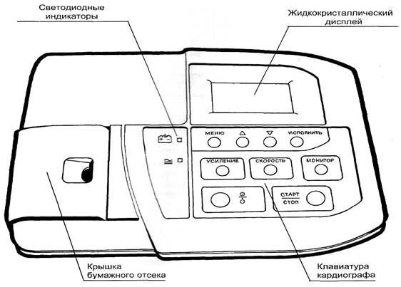
Открытая
крышка бумажного отсека позволяет
получить доступ к внутренним частям ЭК
и поэтому требует осторожности. При
замене бумаги ЭК не должен быть подключен
к пациенту.
Разъем
«ПИТ.12В» предназначен для
подключения ЭК только к питанию
постоянного тока специально оборудованного
автомобиля скорой помощи. Запрещается
подключать к этому разъему любые другие
источники питания.
Н азначение изделия
ЭК
предназначен для проведения
электрокардиографических обследований
по типовым методикам МЗ РФ в качестве
портативного электрокардиографа
с одновременной регистрацией 12-ти
общепринятых отведений и
выводом их на печать по одному или по
три отведения на термобумагу шириной
58 мм.
ЭК
предназначен для применения в отделениях
функциональной диагностики,
кардиологических отделениях и отделениях
интенсивной терапии больниц
и поликлиник, в автомобилях скорой
помощи, а также для врачей частной
практики.
ЭК
предназначен для эксплуатации в закрытых
помещениях или в салоне автомобиля
скорой помощи при:
-
температуре
окружающего воздуха от 10 до 40ºС; -
относительной
влажности 80% при температуре 25ºС и при
более низких температурах
без конденсации влаги; -
атмосферном
давлении 84-106,7 кПа (630-800 мм. рт. ст.).
Основные технические характеристики
ЭК
обеспечивает следующие режимы регистрации
ЭКГ:
-
регистрация
12-ти отведений одновременно и вывод их
на печать по 1 отведению
вдоль бумаги в ручном или автоматическом
режиме с эффективной шириной
записи каждого отведения до 40 мм; -
регистрация
12-ти отведений одновременно и вывод их
на печать по 3 отведения
вдоль бумаги в ручном или автоматическом
режиме с эффективной шириной
записи каждого отведения до 20 мм; -
регистрация
12-ти отведений в «режиме проб» —
многократная регистрация ЭКГ с заданным
интервалом в течение заданного времени; -
регистрация
12-ти отведений в «режиме аритмии»
— автоматическая регистрация ЭКГ при
обнаружении аритмии или экстрасистол
у пациента; -
регистрация
RR-граммы
в течение заданного времени.
Основные
параметры режима съема электрокардиограммы:
режим, чувствительность, скорость,
включение антитреморного фильтра (30
Гц) и антидрейфовых
фильтров (0,12 и 0,4 Гц), значение ЧСС,
амплитудно-временные параметры
ЭКГ и положение электрической оси
сердца, а также дата и время выводятся
на печать рядом с ЭКГ.
-
Время
регистрации в автоматическом режиме
задается пользователем от 2 до 10 секунд. -
ЭК
обеспечивает индикацию о нарушении
контакта электродов с пациентом.
Питание
электрокардиографа осуществляется от:
-
сети
переменного тока частотой 50 Гц напряжением
от 198 до 242В; -
бортовой
сети автомобиля скорой помощи напряжением
от 10 до 15В: -
внутреннего
источника питания — аккумуляторной
батареи 7,2В (от 6 до 8В). Заряд внутренних
аккумуляторов осуществляется при
питании ЭК от сети переменного тока
или от бортовой сети специально
оборудованного автомобиля скорой
помощи.
Мощность,
потребляемая ЭК не превышает 10 ВА.
Д
иапазон
напряжений регистрируемых входных
сигналов в пределах от 0,03 мВ до
5 мВ (размах).
Чувствительность
может быть установлена 5; 10 или 20 мм/мВ
в режимах печати
по одному отведению вдоль бумаги и 2,5;
5 или 10 мм/мВ в режимах печати по
три отведения вдоль бумаги.
Полоса
пропускания тракта усиления ЭК от 0,05
до 75 Гц.
В
ЭК предусмотрены следующие фильтры
сигнала ЭКГ:
-
Отключаемый
антидрейфовый фильтр верхних частот
с частотой среза 0,12 Гц; -
Отключаемый
антидрейфовый фильтр верхних частот
с частотой среза 0,4 Гц; -
Отключаемый
антитреморный фильтр нижних частот с
частотой среза 30 Гц; -
Режекторный
фильтр подавления помех от сети — 50 Гц
(включен постоянно).
Постоянная
времени тракта усиления ЭК при выключенном
антидрейфовом фильтре
— не менее 3,2 сек.
-
Скорость
печати может быть установлена 25 или 50
мм/сек.
Пределы
допускаемой относительной погрешности
измерения интервалов времени
в диапазоне интервалов времени от 0,1 до
1,0 сек. не более ±7 %.
-
ЭК
рассчитан на использование стандартной
термобумаги шириной 58 мм, длина
рулона до 25м (внешний диаметр рулона
не более 48 мм), диаметр внутренней
втулки 12 мм.
Время
установления рабочих режимов ЭК (включая
время успокоения фильтра
3,2 сек.) не превышает 1 мин после включения
питания и установки электродов.
Время
непрерывной работы ЭК не менее 8 ч в
сутки.
Наружные
поверхности ЭК устойчивы к дезинфекции
по ОСТ 42-21-2-85 3% раствором
перекиси водорода с добавлением 0,5 %
моющего средства типа «Лотос»,
«Астра».
ЭК
защищен от воздействия импульсов
дефибриллятора по ГОСТ Р 50267.25- 94.
Масса
ЭК в комплекте не более 3,5 кг.
Г
абаритные
размеры блока электрокардиографического
245x182x60 мм.
Соседние файлы в предмете [НЕСОРТИРОВАННОЕ]
- #
- #
- #
- #
- #
- #
- #
- #
- #
- #
- #
ЭЛЕКТРОКАРДИОГРАФ
ЭКЗТ-01-РД
порядок
проверки
электрокардиографа:
включить
электрокардиограф,
загорится
зеленый
индикатор
если
аккумулятор
разряжен,
горит красный
индикатор 2
выключить
электрокардиограф
порядок
зарядки
электрокардиографа:
включить
электрокардиограф
в сеть,
загорится
зеленый
индикатор
если
желтый
индикатор
«аккумулятор
со стрелкой»
3 горит,
зарядка есть
если
индикатор не
горит,
зарядка закончилась
заряжать
3-4ч
ВО
ВРЕМЯ
ЗАРЯДКИ
АККУМУЛЯТОРА
НЕ
ОБРАЩАТЬ
ВНИМАНИЕ НА
КОЛИЧЕСТВО
ЗАРЯДА
БАТАРЕИ на
жидкокристаллическом
дисплее
после
зарядки
отключить
прибор от сети
порядок
работы:
включить
электрокардиограф
КЛАВИАТУРА
КАРДИОГРАФА
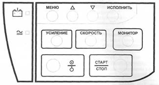
кнопка
«работа/ожидание»
«включение/выключение»
СТАРТ/СТОП
кнопка
включения/выключения
регистрации
ЭКГ
УСИЛЕНИЕ
установка
усиления
сигнала
СКОРОСТЬ
установка
скорости
печати
МОНИТОР
включение/выключение
мониторного
режима
МЕНЮ
кнопка
вызова меню
p
кнопка передвижения
вверх по меню
(или
увеличение
параметра)
q
кнопка
передвижения
вниз по меню
(или уменьшение
параметра)
ИСПОЛНИТЬ
кнопка
выбора
пункта меню.
ЭКРАН
КАРДИОГРАФА
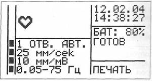
столбик-индикатор
амплитуды
снимаемого
сигнала ЭКГ
отображает
максимальную
амплитуду
сигнала ЭКГ
из всех выбранных
для печати
отведений
частота
пульса
(крупными
цифрами) и символ,
мигающий в
такт с
пульсом
пациента
выбранный
режим
отведений
скорость
25 или 50мм/сек
усиление
5, 10 или 20мм/мВ
полоса
пропускания
тракта
усиления ЭК
(состояние
фильтров)
текущая
дата и время
заряд
аккумуляторов
в процентах.
СООБЩЕНИЯ
О СОСТОЯНИИ
ЭЛЕКТРОКАРДИОГРАФА
ГОТОВ
готов к
регистрации
ЭКГ
НЕТ БУМАГИ
закончилась
бумага
ЗАПРАВКА
БУМАГИ
крышка
бумажного отсека
не закрыта
ОБРЫВ X обрыв
(или плохой
контакт)
электрода X
или перегрузка
усилителя
ПЕРЕГРЕВ
ГОЛОВКИ
печать
прекращена
из-за
перегрева
головки
термопринтера
в
правой
нижней части
экрана режим работы
ЭК — ПЕЧАТЬ
(обычный)
RR-ГРАММА
ПРОБЫ АРИТМИЯ
Новое поколение одно-трехканального электрокардиографа.
Используется везде, где необходим электрокардиограф — от врача частной практики до крупных больниц, машин скорой помощи и санавиации. Имеется возможность комплектации прибора различными интерфейсами для подключения к больничной сети и передачи ЭКГ на центральный кардиопульт.
Запросить коммерческое предложение
Смотреть видеоинструкцию
- Основные функции
- Технические характеристики
- Комплекты поставок
- Сертификаты
- Главная
- Продукция
- Электрокардиографы
- Электрокардиограф ЭК3Т-01-«Р-Д»
Сайт https://www.monitor-ltd.ru/ использует файлы «cookie» с целью повышения удобства пользования веб-сайтом. Продолжая использовать наш сайт, Вы даете согласие на обработку персональных данных. Если вы не хотите использовать файлы «cookie», измените настройки своего браузера.
Электрокардиограф одно-трехканальный ЭКЗТ-01-Р-Д/1 с комбинированным питанием и цветным экраном — предназначен для проведения электрокардиографических исследований с режимом записи 1 или 3 отведений ритма и выводом их на печать на термобумагу шириной 57 мм.
Электрокардиограф компактный ЭК3Т-01-Р-Д/1 применяется во всех сферах современной медицины – в отделениях функциональной диагностики, кардиологии и интенсивной терапии стационаров; в автомобилях скорой медицинской помощи; в частной медицинской практике; в санавиации.
Характеристики и описание
Обращаем Ваше внимание, что информация на сайте носит информационный характер, может быть изменена без уведомления, подлежит уточнению при заказе и не является основанием для претензий.
- Преимущества
- Характеристики
- Комплектация
- Данные для транспортировки
- Режим записи и печати одного или трех отведений ритма;
- Наличие цветного TFT дисплея с диагональю 88 мм для просмотра ЭКГ;
- Возможность одновременного просмотра 12 отведений ЭКГ на дисплее;
- Встроенный автоматический анализ ЭКГ в базовом комплекте, что исключает рутинную работу по измерению амплитудно-временных параметров ЭКГ;
- Автоматический старт записи при обнаружении аритмии, что позволяет существенно экономить бумагу;
- 10 пользовательских профилей с настраиваемыми параметрами;
- Функция обнаружения кардиостимулятора и защиты от дефибрилляций;
- Возможность печати ЭКГ на встроенном термопринтере на рулонной бумаге шириной 57 мм;
- Возможность подключения к компьютеру для вывода информации и архивации полученных данных;
- Наличие разъема USB для подключения внешнего принтера, сканера штрих-кодов и клавиатуры;
- Встроенные антитреморный и антидрейфовый фильтры;
- Возможность дооснащения интерфейсами LAN или Wi-Fi для включения кардиографа в больничную компьютерную сеть (опция);
- Возможность снятия ЭКГ с детей (опция);
- Возможность установки ПО «ArMaSoft-12-Cardio» для расширенного анализа и вывода синдромального заключения по ЭКГ в автоматическом режиме (опция);
- Передача данных по каналу GSM (опция);
- Возможность работы в составе комплекса для проведения нагрузочных проб (опция);
- Регистрационное Удостоверение РФ и Сертификат Соответствия ГОСТ Р.
| Ширина бумаги, мм | 57 |
| Диагональ экрана, мм | 88 |
| Разрешение экрана | 320х240 |
| Чувствительность, мм/мВ | 2,5; 5; 10; 20 или 40 |
| Скорость печати, мм/сек | 5; 10; 12,5; 25 или 50 |
| Потребляемая мощность, ВА | 30 |
| Длина, мм | 202 |
| Ширина, мм | 276 |
| Высота, мм | 64 |
| Вес, кг | 1.2 |
| Блок электрокардиографический со встроенным термопринтером и зарядным устройством | 1 шт. |
| Кабель электродный | 1 шт. |
| Кабель сетевой | 1 шт. |
| Комплект ЭКГ электродов | 1 комплект |
| Рулон термобумаги | 1 шт. |
| Гель электродный | 1 шт. |
| Руководство по эксплуатации | 1 шт. |
| Вес в упаковке, кг | 1.4 |
| Объем, м3 | 0.008 |
| Длина, мм | 250 |
| Ширина, мм | 310 |
| Высота, мм | 100 |
- Похожие товары