-
Contents
-
Table of Contents
-
Bookmarks
Quick Links
Functional Safety
Switch Amplifier
KFD2-SR2-Ex*.W(.LB)
Manual
2
ISO9001
Related Manuals for Pepperl+Fuchs KFD2-SR2-Ex Series
Summary of Contents for Pepperl+Fuchs KFD2-SR2-Ex Series
-
Page 1
Functional Safety Switch Amplifier KFD2-SR2-Ex*.W(.LB) Manual ISO9001… -
Page 2
Phone: +49 621 776 — 0 E-mail: info@de.pepperl-fuchs.com North American Headquarters Pepperl+Fuchs Inc. 1600 Enterprise Parkway Twinsburg, Ohio 44087 Phone: +1 330 425-3555 E-mail: sales@us.pepperl-fuchs.com Asia Headquarters Pepperl+Fuchs Pte. Ltd. P+F Building 18 Ayer Rajah Crescent Singapore 139942 Phone: +65 6779-9091 E-mail: sales@sg.pepperl-fuchs.com https://www.pepperl-fuchs.com… -
Page 3: Table Of Contents
Functional Safety KFD2-SR2-Ex*.W(.LB) Contents Introduction …………5 Content of this Document .
-
Page 4
Functional Safety KFD2-SR2-Ex*.W(.LB) Contents… -
Page 5: Introduction
Additionally, the following parts may belong to the documentation, if applicable: • EU-type examination certificate • EU declaration of conformity • Attestation of conformity • Certificates • Control drawings • FMEDA report • Assessment report • Additional documents For more information about Pepperl+Fuchs products with functional safety, see www.pepperl-fuchs.com/sil.
-
Page 6: Safety Information
Functional Safety KFD2-SR2-Ex*.W(.LB) Introduction Safety Information Target Group, Personnel Responsibility for planning, assembly, commissioning, operation, maintenance, and dismounting lies with the plant operator. Only appropriately trained and qualified personnel may carry out mounting, installation, commissioning, operation, maintenance, and dismounting of the product. The personnel must have read and understood the instruction manual and the further documentation.
-
Page 7: Symbols Used
Functional Safety KFD2-SR2-Ex*.W(.LB) Introduction Symbols Used This document contains symbols for the identification of warning messages and of informative messages. Warning Messages You will find warning messages, whenever dangers may arise from your actions. It is mandatory that you observe these warning messages for your personal safety and in order to avoid property damage.
-
Page 8: Product Description
Product Description Product Description Validity This manual is only valid for devices with a part number greater than #203350. Contact your Pepperl+Fuchs representative for information about older devices. Function KFD2-SR2-Ex1.W This isolated barrier is used for intrinsic safety applications. The device transfers digital signals from NAMUR sensors or dry contacts from the hazardous area to the non-hazardous area.
-
Page 9: Interfaces
• Non-safety relevant interfaces: fault indication output Note For corresponding connections see datasheet. Marking Pepperl+Fuchs Group Lilienthalstraße 200, 68307 Mannheim, Germany Internet: www.pepperl-fuchs.com KFD2-SR2-Ex1.W, KFD2-SR2-Ex2.W, KFD2-SR2-Ex1.W.LB Up to SIL 2 The *-marked letters of the type code are placeholders for versions of the device.
-
Page 10: Planning
Functional Safety KFD2-SR2-Ex*.W(.LB) Planning Planning System Structure 3.1.1 Low Demand Mode of Operation If there are two control loops, one for the standard operation and another one for the functional safety, then usually the demand rate for the safety loop is assumed to be less than once per year.
-
Page 11: Assumptions
Functional Safety KFD2-SR2-Ex*.W(.LB) Planning Assumptions The following assumptions have been made during the FMEDA: • Failure rates are constant, wear is not considered. • Failure rate based on the Siemens standard SN 29500. • The safety-related device is considered to be of type A device with a hardware fault tolerance of 0.
-
Page 12: Safety Function And Safe State
Functional Safety KFD2-SR2-Ex*.W(.LB) Planning Safety Function and Safe State Safe State In the safe state of the safety function the output is de-energized. Safety Function for 1-channel Devices KFD2-SR2-Ex1.W S1 position I (normal The safe state is reached if the NAMUR sensor input operation) is in the off state.
-
Page 13
Functional Safety KFD2-SR2-Ex*.W(.LB) Planning LB/SC Diagnosis If the line fault detection is active (mandatory, see datasheet), the input loops of all device versions are supervised. The line fault detection is activated if switch S3 is in position I. The related safety function is defined as the outputs are de-energized (safe state), if there is a line fault detected. -
Page 14: Characteristic Safety Values
Functional Safety KFD2-SR2-Ex*.W(.LB) Planning Characteristic Safety Values Parameters Characteristic values Assessment type and Full assessment documentation Device type Mode of operation Low demand mode or high demand mode Safety function Output is de-energized 113 FIT 0 FIT 37.8 FIT …
-
Page 15: Useful Lifetime
Functional Safety KFD2-SR2-Ex*.W(.LB) Planning Useful Lifetime Although a constant failure rate is assumed by the probabilistic estimation this only applies provided that the useful lifetime of components is not exceeded. Beyond this useful lifetime, the result of the probabilistic estimation is meaningless as the probability of failure significantly increases with time.
-
Page 16: Mounting And Installation
Functional Safety KFD2-SR2-Ex*.W(.LB) Mounting and Installation Mounting and Installation Mounting and Installing the Device Observe the safety instructions in the instruction manual. Observe the information in the manual. Observe the requirements for the safety loop. Connect the device only to devices that are suitable for this safety application. Check the safety function to ensure the expected output behavior.
-
Page 17: Operation
Functional Safety KFD2-SR2-Ex*.W(.LB) Operation Operation Danger! Danger to life from missing safety function If the safety loop is put out of service, the safety function is no longer guaranteed. • Do not deactivate the device. • Do not bypass the safety function. •…
-
Page 18
Functional Safety KFD2-SR2-Ex*.W(.LB) Operation 5.1.1 Procedure for Manual Proof Test Equipment required: • Digital multimeter with an accuracy of 0.1 % Use for the proof test of the intrinsic safety side of the device a special digital multimeter for intrinsically safe circuits. If intrinsically safe circuits are operated with non-intrinsically safe circuits, they must no longer be used as intrinsically safe circuits. -
Page 19
Functional Safety KFD2-SR2-Ex*.W(.LB) Operation Multimeter KFD2-SR2-Ex1.W (mA) 240 :/2.5 W 24 V DC Multimeter (mA) Multimeter (mA) 24 V DC Zone 0, 1, 2 Zone 2 Power I supply Supply Div. 2 Div. 1, 2 supply Figure 5.1 Proof test set-up for KFD2-SR2-Ex1.W Multimeter KFD2-SR2-Ex1.W.LB (mA) -
Page 20
Functional Safety KFD2-SR2-Ex*.W(.LB) Operation Multimeter KFD2-SR2-Ex2.W (mA) 240 :/2.5 W 24 V DC Multimeter (mA) Multimeter (mA) 240 :/2.5 W 24 V DC Multimeter (mA) Multimeter (mA) 24 V DC Zone 0, 1, 2 Zone 2 Power I supply Supply Div. -
Page 21: Maintenance And Repair
Functional Safety KFD2-SR2-Ex*.W(.LB) Maintenance and Repair Maintenance and Repair Danger! Danger to life from missing safety function Changes to the device or a defect of the device can lead to device malfunction. The function of the device and the safety function is no longer guaranteed. Do not repair, modify, or manipulate the device.
-
Page 22: List Of Abbreviations
Functional Safety KFD2-SR2-Ex*.W(.LB) List of Abbreviations List of Abbreviations Diagnostic Coverage of dangerous faults Failure In Time in 10 Failure Mode, Effects, and Diagnostics Analysis FMEDA Probability of safe failure Probability of dangerous detected failure Probability of dangerous undetected failure …
-
Page 23
Functional Safety KFD2-SR2-Ex*.W(.LB) Notes… -
Page 24
Pepperl+Fuchs Quality Download our latest policy here: www.pepperl-fuchs.com/quality www.pepperl-fuchs.com © Pepperl+Fuchs · Subject to modifications Printed in Germany / DOCT-6656A…
Артикул: 132959
Барьер искрозащиты для сигналов DI. 1 канал
Производитель:
PEPPERL+FUCHS
Производитель: PEPPERL+FUCHS
Технические данные PDF
Краткое описание: технические характеристики KFD2-SR2-EX1.W.LB
| General specifications | ||
|---|---|---|
| Signal type | Digital Input | |
| Functional safety related parameters | ||
| Safety Integrity Level (SIL) | SIL 2 | |
| Supply | ||
| Connection | Power Rail or terminals 14+, 15- | |
| Rated voltage | 20 … 30 V DC | |
| Ripple | ≤ 10 % | |
| Rated current | ≤ 50 mA | |
| Power dissipation | 1 W | |
| Power consumption | < 1.3 W | |
| Input | ||
| Connection side | field side | |
| Connection | terminals 1+, 2+, 3- | |
| Rated values | acc. to EN 60947-5-6 (NAMUR) | |
| Open circuit voltage/short-circuit current | approx. 8 V DC / approx. 8 mA | |
| Switching point/switching hysteresis | 1.2 … 2.1 mA / approx. 0.2 mA | |
| Line fault detection | breakage I ≤ 0.1 mA , short-circuit I > 6 mA | |
| Pulse/Pause ratio | min. 20 ms / min. 20 ms | |
| Output | ||
| Connection side | control side | |
| Connection | output I: terminals 7, 8, 9 ; output II: terminals 10, 11, 12 | |
| Output I | signal ; relay | |
| Output II | signal or error message ; relay | |
| Contact loading | 253 V AC/2 A/cos φ > 0.7; 126.5 V AC/4 A/cos φ > 0.7; 40 V DC/2 A resistive load | |
| Minimum switch current | 2 mA / 24 V DC | |
| Energized/De-energized delay | approx. 20 ms / approx. 20 ms | |
| Mechanical life | 107 switching cycles | |
| Transfer characteristics | ||
| Switching frequency | ≤ 10 Hz | |
| Galvanic isolation | ||
| Input/Output | reinforced insulation according to IEC/EN 61010-1, rated insulation voltage 300 Veff | |
| Input/power supply | reinforced insulation according to IEC/EN 61010-1, rated insulation voltage 300 Veff | |
| Output/power supply | reinforced insulation according to IEC/EN 61010-1, rated insulation voltage 300 Veff | |
| Output/Output | reinforced insulation according to IEC/EN 61010-1, rated insulation voltage 300 Veff | |
| Indicators/settings | ||
| Display elements | LEDs | |
| Control elements | DIP-switch | |
| Configuration | via DIP switches | |
| Labeling | space for labeling at the front | |
| Directive conformity | ||
| Electromagnetic compatibility | ||
| Directive 2014/30/EU | EN 61326-1:2013 (industrial locations) | |
| Low voltage | ||
| Directive 2014/35/EU | EN 61010-1:2010 | |
| Conformity | ||
| Electromagnetic compatibility | NE 21:2006 | |
| Degree of protection | IEC 60529:2001 | |
| Input | EN 60947-5-6:2000 | |
| Ambient conditions | ||
| Ambient temperature | -20 … 60 °C (-4 … 140 °F) | |
| Mechanical specifications | ||
| Degree of protection | IP20 | |
| Connection | screw terminals | |
| Mass | approx. 150 g | |
| Dimensions | 20 x 119 x 115 mm (0.8 x 4.7 x 4.5 inch) , housing type B2 | |
| Mounting | on 35 mm DIN mounting rail acc. to EN 60715:2001 | |
| Data for application in connection with hazardous areas | ||
| EU-type examination certificate | PTB 00 ATEX 2080 | |
| Marking |  II (1)G [Ex ia Ga] IIC II (1)D [Ex ia Da] IIIC I (M1) [Ex ia Ma] I II (1)G [Ex ia Ga] IIC II (1)D [Ex ia Da] IIIC I (M1) [Ex ia Ma] I |
|
| Input | Ex ia | |
| Voltage | 10.5 V | |
| Current | 13 mA | |
| Power | 34 mW (linear characteristic) | |
| Supply | ||
| Maximum safe voltage | 253 V AC / 125 V DC (Attention! Um is no rated voltage.) | |
| Output | ||
| Contact loading | 253 V AC/2 A/cos φ > 0.7; 126.5 V AC/4 A/cos φ > 0.7; 40 V DC/2 A resistive load | |
| Maximum safe voltage | 253 V AC (Attention! The rated voltage can be lower.) | |
| Fault indication output | ||
| Maximum safe voltage | 40 V DC (Attention! Um is no rated voltage.) | |
| Certificate | PF 08 CERT 0803 | |
| Marking | II (3)G [Ex ic Gc] IIC |
|
| Input | Ex ic | |
| Voltage | 10.5 V | |
| Current | 13 mA | |
| Power | 34 mW (linear characteristic) | |
| Output | ||
| Contact loading | 253 V AC/2 A/cos φ > 0.7; 126.5 V AC/4 A/cos φ > 0.7; 40 V DC/2 A resistive load | |
| Certificate | TÜV 99 ATEX 1493 X | |
| Marking | II 3G Ex nA nC IIC T4 |
|
| Output | ||
| Contact loading | 50 V AC/4 A/cos φ > 0.7; 40 V DC/2 A resistive load | |
| Galvanic isolation | ||
| Input/Output | safe electrical isolation acc. to IEC/EN 60079-11, voltage peak value 375 V | |
| Input/power supply | safe electrical isolation acc. to IEC/EN 60079-11, voltage peak value 375 V | |
| Directive conformity | ||
| Directive 2014/34/EU | EN 60079-0:2012+A11:2013 , EN 60079-11:2012 , EN 60079-15:2010 | |
| International approvals | ||
| FM approval | ||
| Control drawing | 116-0035 | |
| UL approval | ||
| Control drawing | 116-0145 | |
| CSA approval | ||
| Control drawing | 116-0047 | |
| IECEx approval | IECEx PTB 11.0034 | |
| Approved for | [Ex ia Ga] IIC, [Ex ia Da] IIIC, [Ex ia Ma] I | |
| General information | ||
| Supplementary information | Observe the certificates, declarations of conformity, instruction manuals, and manuals where applicable. For information see www.pepperl-fuchs.com. | |
| Accessories | ||
| Optional accessories | — power feed module KFD2-EB2(.R4A.B)(.SP) — universal power rail UPR-03(-M)(-S) — profile rail K-DUCT-BU(-UPR-03) |
Оформить заказ на KFD2-SR2-EX1.W.LB вы можете в компании compeq-pepperl отправив заявку по почте, а также по телефону или в офисе компании.
Вам может понравиться
Барьер искрозащиты. 2 канала
Барьер искрозащиты. 1 канал
Барьер искрозащиты для датчиков температуры, универсальный. 1 канал.
Барьер искрозащиты для датчиков температуры, универсальный. 1 канал.
Барьер искрозащиты для датчиков температуры, универсальный. 2 канала.

1
103
36
7_
EN
G.xm
l
2
003
-03-
2
5
Subject to reasonable modifications due to technical advances.
Copyright Pepperl+Fuchs, Printed in Germany
Pepperl+Fuchs Group • Tel.: Germany +49 621 776-0 • USA +1 330 4253555 • Singapore +65 67799091 • Internet http://www.pepperl-fuchs.com
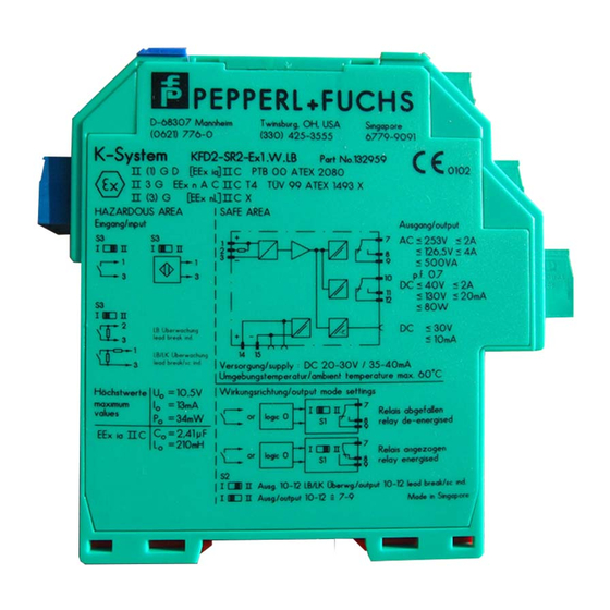
KFD2-SR2-Ex1.W
Isolated switch amplifiers
yellow
green
Output
Power
supply
Saf
e area
Input I EEx ia IIC
Switch S3 in position I
Switch S3 in position I
Switch S3 in position I
Switch S3 in position II
Hazar
dous area
LB
SC
red
Power
Rail
LB/SC
collective
error message
only
KFD2-SR2-Ex1.W
without LB, SC
without SC
&
3-
1+
7
8
9
S1
14 15
+
+
—
2+
II
I
1+
3-
1+
3-
3-
2+
3-
1+
10 k
Ω
10 k
Ω
400
Ω ≤ R ≤ 2 kΩ
S3
—
Composition
24 V DC
• 1-channel
• Control circuit EEx ia IIC
• Reversible mode of operation
• 1 relay output with 1 changeover
contact
• EMC acc. to NAMUR NE 21
• LB/SC monitoring
• LB/SC collective error message via
Power Rail
• Usable up to SIL 2 acc. to IEC 61508
The transformer isolated barrier
transfers digital signals from the
hazardous area. Sensors per
DIN EN 60947-5-6 (NAMUR) and
mechanical contacts may be used as
alarms. Control circuits are monitored
for lead breakage (LB) and short circuit
(SC). The external faults are indicated
according to NAMUR NE44 by a red
flashing LED. For type KFD2-SR2-
Ex1.W, an LB/SC collective error
message is in addition transferred
through the Power Rail to the power
feed module. The intrinsically safe input
is per DIN EN 50020 safely isolated
from the output and the power supply.
The relay output is in accordance with
IEC 61140 safely isolated from the
power supply.
Function
Output: relay