Search by model number
Not sure how to find model number? Click here
If you still can’t find the model, you may try to click on EOL
| Model | Material | Version | OS | Language | Release Date | Download | Checksum |
|---|---|---|---|---|---|---|---|
| GS1200-8 | Declaration GS1200-8, DoC, CE |
007.214-01-00912 | English | 08/31/2023 | Download File
|
||
| GS1200-8 | Datasheet | 5 | English | 01/13/2023 | Download File | ||
| GS1200-8 | Firmware | V2.00(ABME.2)C0 | English | 11/09/2022 | Download File
|
||
| GS1200-8 | Certification GS1200-8, Regulation Certificates for EMC, CE Certificate/ Regulation Report |
002.351-01-00863 | English | 09/22/2022 | Download File | ||
| GS1200-8 | User’s Guide | V2.00_Ed1 | English | 12/21/2021 | Download File | ||
| GS1200-8 | Firmware | V2.00(ABME.1)C0 | English | 10/13/2021 | Download File
|
||
| GS1200-8 | Certification GS1200-8, Regulation Certificates for Safety, CE-LVD Certificate/ Regulation Report |
002.351-02-00548 | English | 01/27/2021 | Download File | ||
| GS1200-8 | Firmware | V2.00(ABME.0)C0 | English | 11/09/2020 | Download File
|
||
| GS1200-8 | Declaration GS1200-8, DoC, Taiwan RoHS |
001.214-01-00973 | Chinese | 01/22/2018 | Download File | ||
| GS1200-8 | Quick Start Guide | 001 | Multiple languages | 01/05/2018 | Download File | ||
| GS1200-8 | Certification GS1200-8, Regulation Certificates for EMC, FCC Certificate/ Regulation Report |
001.351-01-00864 | English | 11/29/2017 | Download File |
- Manuals
- Brands
- ZyXEL Communications Manuals
- Switch
- GS1200 SERIES
- User manual
-
Contents
-
Table of Contents
-
Troubleshooting
-
Bookmarks
Quick Links
User’s Guide
GS1200 Series
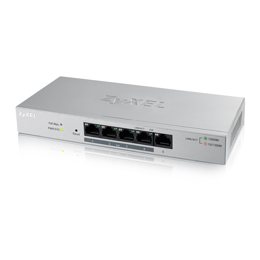
GS1200-5 / GS1200-5HP v2 / GS1200-8 / GS1200-8HP v2
5-Port / 8-Port Web Managed (PoE) Gigabit Switch
Default Login Details
LAN IP Address
Password
Copyright © 2020 Zyxel Communications Corporation
http://192.168.1.3
1234
Version 2.00 Edition 1, 11/2020
Related Manuals for ZyXEL Communications GS1200 Series
Summary of Contents for ZyXEL Communications GS1200 Series
-
Page 1
User’s Guide GS1200 Series GS1200-5 / GS1200-5HP v2 / GS1200-8 / GS1200-8HP v2 5-Port / 8-Port Web Managed (PoE) Gigabit Switch Default Login Details Version 2.00 Edition 1, 11/2020 LAN IP Address http://192.168.1.3 Password 1234 Copyright © 2020 Zyxel Communications Corporation… -
Page 2
Related Documentation • Quick Start Guide The Quick Start Guide shows how to connect the Switch and access the Web Configurator. • More Information Go to support.zyxel.com to find other information on the Switch GS1200 Series User’s Guide… -
Page 3: Document Conventions
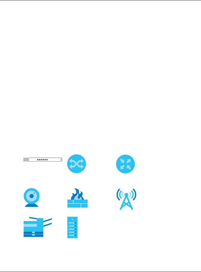
Icons Used in Figures Figures in this user guide may use the following generic icons. The Switch icon is not an exact representation of your device. Switch Generic Switch Generic Router IP Camera Firewall Cell Tower Printer Server GS1200 Series User’s Guide…
-
Page 4: Table Of Contents
Initial Setup Example ……………………..24 Tutorials …………………………27 Technical Reference ……………………39 System …………………………40 Port …………………………… 44 VLAN …………………………50 Link Aggregation ……………………..53 Mirroring …………………………55 QoS …………………………… 57 IGMP Snooping ……………………….. 61 Management ……………………….63 Troubleshooting ………………………. 67 GS1200 Series User’s Guide…
-
Page 5: Table Of Contents
3.3 LEDs …………………………18 Chapter 4 Web Configurator……………………..19 4.1 Overview ……………………….19 4.2 System Login ………………………. 19 4.3 Web Configurator Layout ………………….20 4.3.1 Change Your Password ………………….22 4.4 Switch Lockout / Resetting the Switch ………………22 GS1200 Series User’s Guide…
-
Page 6
8.1.1 What You Need to Know ………………… 44 8.2 Port Settings ……………………….. 46 8.2.1 Advanced Settings ………………….. 47 Chapter 9 VLAN…………………………50 9.1 Overview ……………………….50 9.1.1 IEEE 802.1Q Tagged VLANs ………………..50 9.2 VLAN Settings ……………………..51 Chapter 10 Link Aggregation ……………………..53 GS1200 Series User’s Guide… -
Page 7
Chapter 15 Troubleshooting……………………..67 15.1 Power, Hardware Connections, and LEDs …………….. 67 15.2 Switch Access and Login ………………….68 15.3 Switch Configuration ……………………70 Appendix A Customer Support ………………….. 71 Appendix B Legal Information ………………….77 Index …………………………81 GS1200 Series User’s Guide… -
Page 8: User’s Guide
User’s Guide…
-
Page 9: Getting To Know Your Switch
H A P T E R Getting to Know Your Switch 1.1 Introduction This chapter introduces the main features and applications of the Switch. The GS1200 Series consists of the following models: • GS1200-5 • GS1200-5HP v2 • GS1200-8 • GS1200-8HP v2 You can easily connect different devices, such as computers, network storage devices, IP cameras, print servers to your home network.
-
Page 10: Applications
Chapter 1 Getting to Know Your Switch Table 1 GS1200 Series Comparison Table (continued) MODEL GS1200-5 GS1200-5HP V2 GS1200-8 GS1200-8HP V2 PoE Feature – IEEE 802.3 af PoE – IEEE 802.3 af PoE IEEE 802.3at High IEEE 802.3at High Power over…
-
Page 11: Vlan Application Example
• Change the password. Use a password that is not easy to guess and that consists of different types of characters, such as numbers and letters. • Write down the password and put it in a safe place. GS1200 Series User’s Guide…
-
Page 12
Switch to its factory default settings. If you backed up an earlier configuration file, you would not have to totally re-configure the Switch. You could simply restore your last configuration. GS1200 Series User’s Guide… -
Page 13: Hardware Installation
Make sure there is enough space around the Switch to allow the attachment of cables and the power cord and allow sufficient air circulation. Note: Make sure you are using the correct type of Ethernet cable (Category 5e, 6UTP/STP, or better Ethernet cable). GS1200 Series User’s Guide…
-
Page 14: Wall Mounting
Switch with the connection cables. Use the mounting holes on the Switch to hang the Switch on the screws. Wall mount the Switch with the Ethernet ports facing down and the ventilation holes on the side. GS1200 Series User’s Guide…
-
Page 15
Chapter 2 Hardware Installation Figure 4 Wall Mounting Figure 5 Screw Specifications GS1200 Series User’s Guide… -
Page 16: Hardware Panels
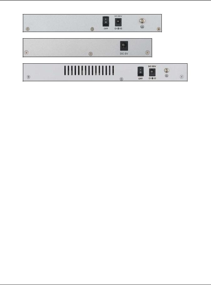
The following figures show the front panels of the Switch. Figure 6 Front Panel: GS1200-5 Figure 7 Front Panel: GS1200-5HP v2 Figure 8 Front Panel: GS1200-8 Figure 9 Front Panel: GS1200-8HP v2 3.2 Rear Panel The following figures show the rear panels of the Switch. GS1200 Series User’s Guide…
-
Page 17: Power Connector
To connect power to the Switch, insert the female end of the power cord to the AC power receptacle on the rear panel. Connect the other end of the supplied power cord to a power outlet. Make sure that no objects obstruct the airflow. GS1200 Series User’s Guide…
-
Page 18: Leds
More than 50 W has been supplied to the PoE-enabled devices, and the PoE power output is approaching the power budget. (GS1200-5HP Less than 50 W has been supplied to the PoE-enabled devices. v2 & GS1200- 8HP v2) GS1200 Series User’s Guide…
-
Page 19: Web Configurator
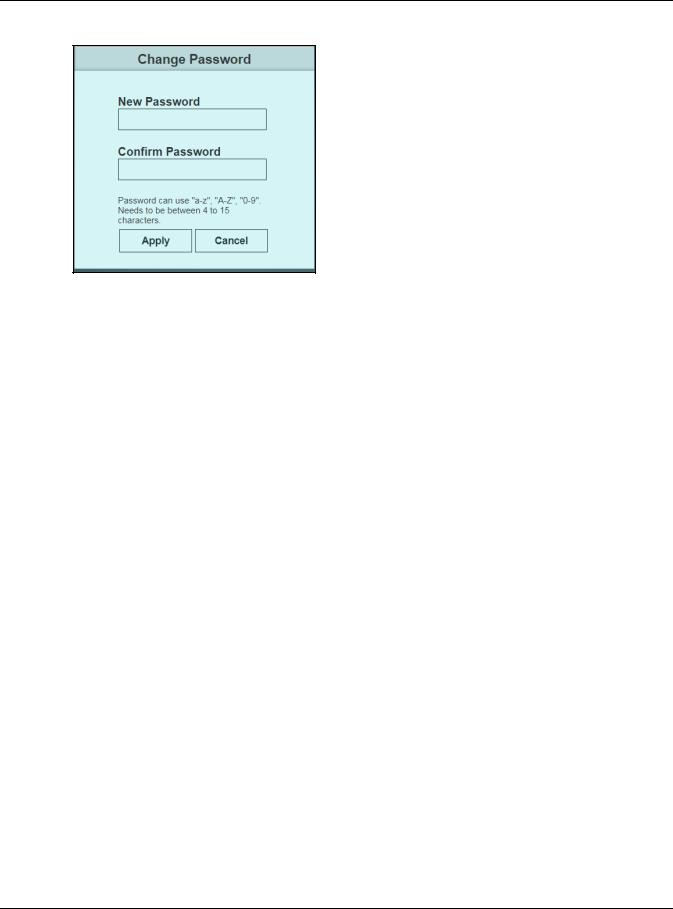
(«a – z», «A – Z», «0 – 9»). The password must be 8 to 15 characters long. Retype it to confirm and click Apply to view the first Web Configurator screen. For GS1200-5HP and GS1200-8HP, you can enter the default password 1234 again, if you do not want to change your password. GS1200 Series User’s Guide…
-
Page 20: Web Configurator Layout
The System screen is the first screen that displays when you access the Web Configurator. This guide uses the GS1200-8 and GS1200-5HP v2 screens as examples. The screens may vary slightly for different models. The following figure shows the navigating components of a Web Configurator screen. GS1200 Series User’s Guide…
-
Page 21
PoE on a port. VLAN This link takes you to a screen where you can set the PVID (Port VLAN ID) on a port and create/ modify/delete IEEE 802.1Q VLAN for the Switch. GS1200 Series User’s Guide… -
Page 22: Change Your Password
4.4 Switch Lockout / Resetting the Switch You could block yourself (and all others) from managing the Switch if you do one of the following: Remove all ports from VLAN1 and you do not configure other VLAN groups. GS1200 Series User’s Guide…
-
Page 23: Logging Out Of The Web Configurator
Web Configurator. You have to log in with your password again after you log out. This is recommended after you finish a management session for security reasons. Note: You are automatically logged out of the Web Configurator after 5 minutes of inactivity. GS1200 Series User’s Guide…
-
Page 24: Initial Setup Example
Enter the new IP address 192.168.1.5 in the IP Address field. Click Apply. The following screen appears. Click OK to save the setting. Connection to the Web Configurator will be lost. Figure 19 Lost Connection Warning GS1200 Series User’s Guide…
-
Page 25: Change The Password
Enter the new password again to in the Confirm Password field for confirmation. Click Apply. You will automatically be logged out of the Web Configurator. A Log in screen appears. Enter the new password and click SIGN IN to log in using the new password. GS1200 Series User’s Guide…
-
Page 26
Chapter 5 Initial Setup Example GS1200 Series User’s Guide… -
Page 27: Tutorials
If you want to have a port (for example port 1) belong to another VLAN as well, say VLAN 2, you need to create a VLAN first, and then add the port to the VLAN. Figure 21 Initial Setup Network Example: VLAN Click VLAN in the navigation panel and click the Create New VLAN button. GS1200 Series User’s Guide…
-
Page 28
Switch to remove VLAN tags before sending. Clicking the port’s check box loops between untagging, non-member, and tagging. Change the box color of other ports not a member of the VLAN group to gray. Click Apply to save the settings. GS1200 Series User’s Guide… -
Page 29: Setting Port Vid
VLAN 2. Figure 22 Initial Setup Network Example: Port VID Click VLAN in the navigation panel. Enter 2 in the PVID field for port 2 and click Apply to save your changes back to the Switch. GS1200 Series User’s Guide…
-
Page 30: Setting Up Bandwidth Control
In the example network, configure three computers (connect to ports 1, 2, and 3) to share 512 Kbps egress bandwidth and 4 Mbps ingress bandwidth. Click Port in the navigation panel and click the Advanced Settings button. GS1200 Series User’s Guide…
-
Page 31
Enter 4000 in the Ingress Rate field and 512 in the Egress Rate field for Port 1. Click the radio button for both. Do the same for Ports 2 and 3. Click Apply to save the settings. GS1200 Series User’s Guide… -
Page 32: Setting Up Qos (Quality Of Service)
The Switch allows four priority levels, shown in the table below. Table 5 Priority Queuing Levels in QoS QUEUE NAME PRIORITY LEVEL Queue 0 Low Priority Queue 1 Normal Priority Queue 2 Medium Priority Queue 3 High Priority GS1200 Series User’s Guide…
-
Page 33
To apply IEEE 802.1p QoS to the Switch, follow these steps: Click the IEEE 802.1p QoS radio button. Choose which priority tags will carry the sensitive data, using the priority queuing levels given. Click on each priority tag’s radio button to assign a priority queue. GS1200 Series User’s Guide… -
Page 34: Upgrade Firmware On The Switch
Type the path and file name of the firmware file you wish to upload to the Switch in the text box or click path to locate it. After you select the firmware file, click the Upgrade button to load the new firmware. GS1200 Series User’s Guide…
-
Page 35: Back Up A Configuration File
Click Management in the navigation panel and click the Backup button. Specify the location where you want to save the backup file. The default filename is switch_cfg.bin. Click the Save button to save and store your current Switch settings. GS1200 Series User’s Guide…
-
Page 36: Restore Configuration
You can upload a previously saved configuration file from your computer to your Switch to restore that previous configuration. Click Management in the navigation panel. Click path and select a .bin file to restore. Figure 27 Restore Configuration Click Restore. The following message appears after a successful restore. Figure 28 Successful Restore GS1200 Series User’s Guide…
-
Page 37: Power Over Ethernet (Poe) Configuration
PoE. Note: The total power the Switch can supply is 60 W, and it is shown in the PoE Total Power field. The maximum power a PoE port can supply is 30 W. GS1200 Series User’s Guide…
-
Page 38
Note: The Switch allocates power to PDs in the order that they were connected. Note: When the total power requested by the PDs exceeds the total PoE power budget on the Switch, the last PD connected to the Switch will not be powered up. GS1200 Series User’s Guide… -
Page 39: Technical Reference
Technical Reference…
-
Page 40: System
7.2 System Screen The System screen displays when you log into the Switch or click System at the top of the Web Configurator. The System screen displays the Switch’s general device information, PoE status, and the port statistics. GS1200 Series User’s Guide…
-
Page 41
Chapter 7 System Figure 29 System The following table describes the labels in this screen. Table 6 System LABEL DESCRIPTION System Information Model Name This field displays the model name of this Switch. GS1200 Series User’s Guide… -
Page 42
2 requires 20 W, and the third one connected to port 3 requires 25 W. In this case, the total power consumption is 65 W which exceeds the maximum power the Switch can supply. Therefore, the third PoE-enabled device will not be powered up as it was connected last. GS1200 Series User’s Guide… -
Page 43
This field displays the amount of power the Switch is currently supplying to the PoE-enabled device connected to the port. (GS1200-5HP v2 & GS1200-8HP Clear Click this button to clear the statistics in the TX(Pkts) and RX(Pkts) fields. Refresh Click this button to update the information in this screen. GS1200 Series User’s Guide… -
Page 44: Port
Loop Detection allows the Switch to discover a loop if it happens, and create a log. Loop Prevention allows the Switch to shut down a port automatically if it discover a loop on that port. See Section 3.3 on page 18 for more information about LEDs. GS1200 Series User’s Guide…
-
Page 45
In the figure below, the IP camera and IP phone are PDs getting their power directly from the Switch PSE. Aside from minimizing the need for cables and wires, PoE removes the hassle of trying to find a nearby electric outlet to power up devices. GS1200 Series User’s Guide… -
Page 46: Port Settings
Chapter 8 Port Figure 34 Powered Device Example 8.2 Port Settings Click Port in the navigation panel to open the following screen. Figure 35 Port GS1200 Series User’s Guide…
-
Page 47: Advanced Settings
GS1200-8HP v2) Advanced Click this button to set up Port Isolation and Bandwidth Control. Settings Apply Click this button to save your changes to the Switch. 8.2.1 Advanced Settings Click Advanced Settings to open the following screen. GS1200 Series User’s Guide…
-
Page 48
All incoming ports are selected while only the uplink port is selected. See Section 8.1.1.3 on page 45 for more details. Otherwise, select Disabled. Apply Click this button to save your changes to the Switch. GS1200 Series User’s Guide… -
Page 49
Specify the maximum bandwidth allowed in kilobits per second (kbps) for the out-going traffic (kbps) flow on a port. Select Unlimited to have the Switch obtain the connection speed of up to 1000 Mbps. Apply Click this button to save your changes to the Switch. GS1200 Series User’s Guide… -
Page 50: Vlan
A broadcast frame (or a multicast frame for a multicast group that is known by the system) is duplicated only on ports that are members of the VID (except the incoming port itself), thus confining the broadcast to a specific domain. Figure 37 Tagged VLAN GS1200 Series User’s Guide…
-
Page 51: Vlan Settings
Enter a number between 1 and 4094 as the port VLAN ID. Apply Click this button to save your PVID settings to the Switch. Maximum number This shows the maximum number of IEEE 802.1Q VLANs you can have on the Switch. of IEEE 802.1Q VLAN GS1200 Series User’s Guide…
-
Page 52
Click Modify to edit the VLAN settings. Delete Click Delete to remove the VLAN group. You cannot delete the default VLAN. Create New VLAN Click this button to configure a new IEEE 802.1Q VLAN for the Switch. GS1200 Series User’s Guide… -
Page 53: Link Aggregation
You may want to trunk (link) ports if for example, it is cheaper to use multiple lower-speed links than to under-utilize a high-speed, but more costly, single-port link. Figure 39 Link Aggregation 10.2 Link Aggregation Use this screen to configure static link aggregation. GS1200 Series User’s Guide…
-
Page 54
3 and 4, and the other contains ports 7 and 8. Note: Make sure the ports in a link aggregation group must have the same PVID and VLAN ID. Apply Click this button to save your changes to the Switch. GS1200 Series User’s Guide… -
Page 55: Mirroring
Use this screen to select a monitor port and specify the traffic flow to be copied to the monitor port. Note: A port cannot be the monitor port and the mirrored port at the same time. Figure 41 Mirroring GS1200 Series User’s Guide…
-
Page 56
Note: Select one monitor port. Mirrored Port Select this option to mirror the traffic on a port. Note: Select one or multiple mirrored ports. Apply Click this button to save your changes to the Switch. GS1200 Series User’s Guide… -
Page 57: Qos
Internet radio or streaming video. Figure 42 QoS 12.2 What You Need to Know The Switch can put packets into the queues according to the port on which the packet is received or the priority tag in the packet. GS1200 Series User’s Guide…
-
Page 58: Port-Based Qos
Video, < 100 ms latency and jitter Voice, < 10 ms latency and jitter Internetwork Control 7 (highest) Network Control Note: Frames without an explicit priority tag are treated as system traffic and assigned to Queue0. Figure 43 IEEE 802.1p QoS GS1200 Series User’s Guide…
-
Page 59: Port-Based Qos Screen
IEEE 802.1P QoS assigns queuing by PCP priority tags. The Switch’s default settings for IEEE 802.1P QoS are shown in the next figure. The numbers from 0 to 7 refer to the priority tags for each traffic type. GS1200 Series User’s Guide…
-
Page 60
Assign the weight (the number you select in the queue Weight field) to each priority. Bandwidth is divided across the different traffic queues according to their weights. Queues with larger weights get more service than queues with smaller weights. Apply Click Apply to save your changes to the Switch. GS1200 Series User’s Guide… -
Page 61: Igmp Snooping
IGMP snooping allows the Switch to learn multicast groups without you having to manually configure them. 13.2 IGMP Snooping Settings Click IGMP Snooping in the navigation panel to display the screen as shown next. GS1200 Series User’s Guide…
-
Page 62
Or, select Auto to allow any port to be used as an IGMP router port after receiving an IGMP query. Note: If link aggregation is enabled, the ports in a link aggregation group will not be available in this field. Apply Click Apply to save your changes to the Switch. GS1200 Series User’s Guide… -
Page 63: Management
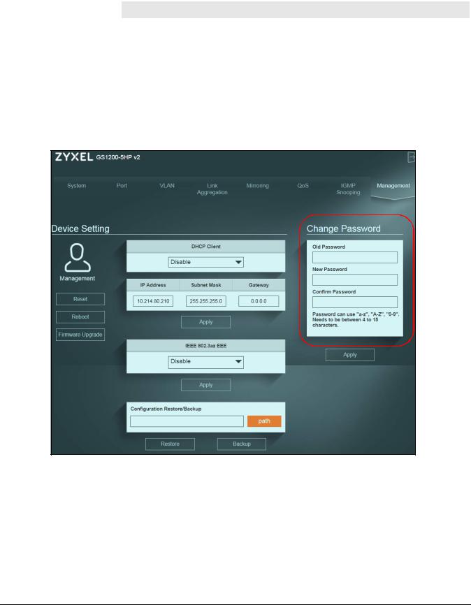
An administrator is someone who can both view and configure Switch changes. The default administrator password is 1234. Note: It is highly recommended that you change the default administrator password (1234). Click Management in the navigation panel to open the following screen. GS1200 Series User’s Guide…
-
Page 64
DHCP Client Select Enable if you have a DHCP server that can assign the Switch an IP address, subnet mask, a default gateway IP address and a domain name server IP address automatically. Otherwise, select Disable. GS1200 Series User’s Guide… -
Page 65: Firmware Upgrade
The following message will appear after you click the Firmware Upgrade button. You will not be able to configure other settings during the firmware upgrade process to avoid system crashes on the Switch. Click OK. GS1200 Series User’s Guide…
-
Page 66
After a successful upload, the system will reboot, and you will need to log into the Switch again. Figure 50 Firmware Upgrade Confirmation If you click the Cancel button in the Firmware Upgrade page, the Switch will reboot, and you will be directed to the login screen. GS1200 Series User’s Guide… -
Page 67: Troubleshooting
Disconnect and re-connect the power adapter or cord to the Switch. If the problem continues, contact the vendor. The PoE LED is off and/or power is not being supplied to my PoE-enabled device. (For GS1200-5HP v2 and GS1200-8HP v2) GS1200 Series User’s Guide…
-
Page 68: Switch Access And Login
If this does not work, you have to reset the device to its factory defaults. See Section 4.4 on page I forgot the password. The default password is 1234. If this does not work, you have to reset the device to its factory defaults. See Section 4.4 on page GS1200 Series User’s Guide…
-
Page 69
Pop-up Windows, JavaScripts and Java Permissions In order to use the Web Configurator you need to allow the following: • Web browser pop-up windows from your device. • JavaScripts (enabled by default). • Java permissions (enabled by default). GS1200 Series User’s Guide… -
Page 70: Switch Configuration
Select the firmware file that you tried to upload to the Switch before and try upgrading the firmware again in the Firmware Upgrade screen. Wait for the firmware upgrade process to complete. After a successful upload, the system will reboot, and you will need to log into the Switch again. GS1200 Series User’s Guide…
-
Page 71: Appendix A Customer Support
• Brief description of the problem and the steps you took to solve it. Corporate Headquarters (Worldwide) Taiwan • Zyxel Communications Corporation • http://www.zyxel.com Asia China • Zyxel Communications (Shanghai) Corp. Zyxel Communications (Beijing) Corp. Zyxel Communications (Tianjin) Corp. • https://www.zyxel.com/cn/zh/ India • Zyxel Technology India Pvt Ltd. • https://www.zyxel.com/in/en/ Kazakhstan •…
-
Page 72
• Zyxel Singapore Pte Ltd. • http://www.zyxel.com.sg Taiwan • Zyxel Communications Corporation • https://www.zyxel.com/tw/zh/ Thailand • Zyxel Thailand Co., Ltd. • https://www.zyxel.com/th/th/ Vietnam • Zyxel Communications Corporation-Vietnam Office • https://www.zyxel.com/vn/vi Europe Belarus • Zyxel BY • https://www.zyxel.by Belgium • Zyxel Communications B.V. • https://www.zyxel.com/be/nl/… -
Page 73
Appendix A Customer Support • https://www.zyxel.com/be/fr/ Bulgaria • Zyxel България • https://www.zyxel.com/bg/bg/ Czech Republic • Zyxel Communications Czech s.r.o • https://www.zyxel.com/cz/cs/ Denmark • Zyxel Communications A/S • https://www.zyxel.com/dk/da/ Estonia • Zyxel Estonia • https://www.zyxel.com/ee/et/ Finland • Zyxel Communications • https://www.zyxel.com/fi/fi/ France •… -
Page 74
• Zyxel Communications Poland • https://www.zyxel.com/pl/pl/ Romania • Zyxel Romania • https://www.zyxel.com/ro/ro Russia • Zyxel Russia • https://www.zyxel.com/ru/ru/ Slovakia • Zyxel Communications Czech s.r.o. organizacna zlozka • https://www.zyxel.com/sk/sk/ Spain • Zyxel Communications ES Ltd. • https://www.zyxel.com/es/es/ Sweden • Zyxel Communications • https://www.zyxel.com/se/sv/ Switzerland •… -
Page 75
Appendix A Customer Support Turkey • Zyxel Turkey A.S. • https://www.zyxel.com/tr/tr/ • Zyxel Communications UK Ltd. • https://www.zyxel.com/uk/en/ Ukraine • Zyxel Ukraine • http://www.ua.zyxel.com South America Argentina • Zyxel Communications Corporation • https://www.zyxel.com/co/es/ Brazil • Zyxel Communications Brasil Ltda. • https://www.zyxel.com/br/pt/ Colombia •… -
Page 76
Appendix A Customer Support Middle East • Zyxel Communications Corporation • https://www.zyxel.com/me/en/ North America • Zyxel Communications, Inc. – North America Headquarters • https://www.zyxel.com/us/en/ Oceania Australia • Zyxel Communications Corporation • https://www.zyxel.com/au/en/ Africa South Africa • Nology (Pty) Ltd. • https://www.zyxel.com/za/en/… -
Page 77: Appendix B Legal Information
The contents of this publication may not be reproduced in any part or as a whole, transcribed, stored in a retrieval system, translated into any language, or transmitted in any form or by any means, electronic, mechanical, magnetic, optical, chemical, photocopying, manual, or otherwise, without the prior written permission of Zyxel Communications Corporation. Published by Zyxel Communications Corporation. All rights reserved.
-
Page 78
Attention: Évitez d’utiliser ce produit (autre qu’un type sans fil) pendant un orage. Il peut y avoir un risque de choc électrique de la foudre. • Attention: Toujours débrancher toutes les lignes téléphoniques de la prise murale avant de réparer ou de démonter ce produit. GS1200 Series User’s Guide… -
Page 79
• 若接上不正確的電源變壓器會有爆炸的風險。 • 請勿隨意更換產品內的電池。 • 如果更換不正確之電池型式,會有爆炸的風險,請依製造商說明書處理使用過之電池。 • 請將廢電池丟棄在適當的電器或電子設備回收處。 • 請勿將設備解體。 • 請勿阻礙設備的散熱孔,空氣對流不足將會造成設備損害。 • 請插在正確的電壓供給插座 ( 如 : 北美 / 台灣電壓 110V AC,歐洲是 230V AC)。 • 假若電源變壓器或電源變壓器的纜線損壞,請從插座拔除,若您還繼續插電使用,會有觸電死亡的風險。 • 請勿試圖修理電源變壓器或電源變壓器的纜線,若有毀損,請直接聯絡您購買的店家,購買⼀個新的電源變壓器。 • 請勿將此設備安裝於室外,此設備僅適合放置於室內。 • 請勿隨⼀般垃圾丟棄。 • 請參閱產品背貼上的設備額定功率。 • 請參考產品型錄或是彩盒上的作業溫度。 GS1200 Series User’s Guide… -
Page 80
Register your product online at www.zyxel.com to receive email notices of firmware upgrades and related information. Trademarks ZyNOS (Zyxel Network Operating System) and ZON (Zyxel One Network) are registered trademarks of Zyxel Communications, Inc. Other trademarks mentioned in this publication are used for identification purposes only and may be properties of their respective owners. -
Page 81: Index
64, 65 certifications firmware version viewing flow control change the password frames clearance received Switch installation transmitted collision signal front panel configuration full duplex mode restore contact information customer support GS1200 Series User’s Guide…
-
Page 82
IGMP leave packet group IGMP multicast router static IGMP packets login snoop password IGMP query port login account select administrator IGMP snooping logout icon default setting loop enable detection 44, 47 IGMP Snooping screen prevention 44, 47 GS1200 Series User’s Guide… -
Page 83
VLAN ID, see PVID out-going traffic Port-Based QoS screen distribution type power connector maximum bandwidth Power over Ethernet (PoE) overheating Power Sourcing Equipment (PSE) prevention powered device (PD) product registration PVID (Port VLAN ID) 29, 50, 51 GS1200 Series User’s Guide… -
Page 84
VLAN 1 fanless-type precaution VLAN screen fan-type precaution VLAN tag fan-type usage precaution VLAN-unaware device IP address 42, 65 VOD (Video on Demand) MAC address manage Voice over IP (VoIP) model list model name name GS1200 Series User’s Guide… -
Page 85
Index wall mounting distance warranty note web browser pop-up window Web Configurator browser support home inactivity layout login logout navigation panel overview recommended screen resolution GS1200 Series User’s Guide…
![]()
User’s Guide
GS1200 Series
GS1200-5/GS1200-5HP v2/GS1200-8/GS1200-8HP v2
5-Port / 8-Port Web Managed (PoE) Gigabit Switch
|
Default Login Details |
Version 1.00 Edition 2, 12/2018 |
||||||||||||||||||||||||
|
LAN IP Address |
http://192.168.1.3 |
||||||||||||||||||||||||
|
Password |
1234 |
||||||||||||||||||||||||
Copyright © 2018 Zyxel Communications Corporation

IMPORTANT!
READ CAREFULLY BEFORE USE.
KEEP THIS GUIDE FOR FUTURE REFERENCE.
This is a User’s Guide for a series of products. Not all products support all firmware features. Screenshots and graphics in this book may differ slightly from your product due to differences in your product firmware or your computer operating system. Every effort has been made to ensure that the information in this manual is accurate.
Related Documentation
•Quick Start Guide
The Quick Start Guide shows how to connect the Switch and access the Web Configurator.
•More Information
Go to support.zyxel.com to find other information on the Switch.
GS1200 Series User’s Guide
2
Document Conventions
Document Conventions
Warnings and Notes
These are how warnings and notes are shown in this guide.
Warnings tell you about things that could harm you or your device.
Note: Notes tell you other important information (for example, other things you may need to configure or helpful tips) or recommendations.
Syntax Conventions
•The GS1200-5, GS1200-5HP v2, GS1200-8, and GS1200-8HP v2 may be referred to as the “Switch” in this guide.
•Product labels, screen names, field labels and field choices are all in bold font.
•A right angle bracket ( > ) within a screen name denotes a mouse click. For example, QoS > PortBased QoS means you first click QoS in the navigation panel, then the Port-Based QoS sub menu to get to that screen.
Icons Used in Figures
Figures in this user guide may use the following generic icons. The Switch icon is not an exact representation of your device.
|
Switch |
Generic Switch |
Generic Router |
|
IP Camera |
Firewall |
Cell Tower |
|
Printer |
Server |
|
GS1200 Series User’s Guide
3

Contents Overview |
|
|
Contents Overview |
|
|
User’s Guide ………………………………………………………………………………………………………………………. |
8 |
|
Getting to Know Your Switch …………………………………………………………………………………………………. |
9 |
|
Hardware Installation …………………………………………………………………………………………………………… |
12 |
|
Hardware Panels …………………………………………………………………………………………………………………. |
13 |
|
The Web Configurator …………………………………………………………………………………………………………. |
16 |
|
Initial Setup Example ……………………………………………………………………………………………………………. |
21 |
|
Technical Reference ………………………………………………………………………………………………………… |
26 |
|
System …………………………………………………………………………………………………………………………………. |
27 |
|
Port ……………………………………………………………………………………………………………………………………… |
30 |
|
VLAN …………………………………………………………………………………………………………………………………… |
34 |
|
Link Aggregation …………………………………………………………………………………………………………………. |
37 |
|
Mirroring ………………………………………………………………………………………………………………………………. |
39 |
|
QoS ……………………………………………………………………………………………………………………………………… |
41 |
|
IGMP Snooping ……………………………………………………………………………………………………………………. |
45 |
|
Management ………………………………………………………………………………………………………………………. |
47 |
|
Troubleshooting …………………………………………………………………………………………………………………… |
51 |
GS1200 Series User’s Guide
4

Table of Contents |
||
|
Table of Contents |
||
|
Document Conventions ………………………………………………………………………………………………………. |
3 |
|
|
Contents Overview ……………………………………………………………………………………………………………… |
4 |
|
|
Table of Contents ………………………………………………………………………………………………………………… |
5 |
|
|
Part I: User’s Guide……………………………………………………………………………….. |
8 |
|
|
Chapter 1 |
||
|
Getting to Know Your Switch ……………………………………………………………………………………………….. |
9 |
|
|
1.1 |
Introduction ……………………………………………………………………………………………………………………… |
9 |
|
1.2 |
Applications …………………………………………………………………………………………………………………… |
10 |
|
1.2.1 Bridging Application ………………………………………………………………………………………………. |
10 |
|
|
1.2.2 VLAN Application Example …………………………………………………………………………………….. |
10 |
|
|
1.3 Ways to Manage the Switch …………………………………………………………………………………………… |
11 |
|
|
1.4 |
Good Habits for Managing the Switch ……………………………………………………………………………. |
11 |
|
Chapter 2 |
||
|
Hardware Installation ………………………………………………………………………………………………………… |
12 |
|
|
2.1 |
Installation Scenarios ………………………………………………………………………………………………………. |
12 |
|
2.2 |
Desktop Installation Procedure ………………………………………………………………………………………. |
12 |
|
Chapter 3 |
||
|
Hardware Panels……………………………………………………………………………………………………………….. |
13 |
|
|
3.1 |
Front Panel …………………………………………………………………………………………………………………….. |
13 |
|
3.2 |
Rear Panel ……………………………………………………………………………………………………………………… |
13 |
|
3.2.1 Power Connector ………………………………………………………………………………………………….. |
14 |
|
|
3.3 |
LEDs ……………………………………………………………………………………………………………………………… |
15 |
|
Chapter 4 |
||
|
The Web Configurator………………………………………………………………………………………………………… |
16 |
|
|
4.1 |
Overview ……………………………………………………………………………………………………………………….. |
16 |
|
4.2 |
System Login ………………………………………………………………………………………………………………….. |
16 |
|
4.3 |
The Web Configurator Layout ………………………………………………………………………………………… |
17 |
|
4.3.1 Change Your Password …………………………………………………………………………………………. |
19 |
|
|
4.4 |
Switch Lockout ……………………………………………………………………………………………………………….. |
19 |
|
4.5 |
Resetting the Switch ………………………………………………………………………………………………………. |
20 |
|
4.6 |
Logging Out of the Web Configurator …………………………………………………………………………… |
20 |
|
GS1200 Series User’s Guide |
5

|
Table of Contents |
||
|
Chapter 5 |
||
|
Initial Setup Example …………………………………………………………………………………………………………. |
21 |
|
|
5.1 |
Overview ……………………………………………………………………………………………………………………….. |
21 |
|
5.1.1 Creating a VLAN ……………………………………………………………………………………………………. |
21 |
|
|
5.1.2 Setting Port VID ………………………………………………………………………………………………………. |
23 |
|
|
5.1.3 Power over Ethernet (PoE) Configuration ……………………………………………………………….. |
24 |
|
|
Part II: Technical Reference………………………………………………………………… |
26 |
|
|
Chapter 6 |
||
|
System………………………………………………………………………………………………………………………………. |
27 |
|
|
6.1 |
Overview ……………………………………………………………………………………………………………………….. |
27 |
|
6.2 |
System Screen ………………………………………………………………………………………………………………… |
27 |
|
Chapter 7 |
||
|
Port …………………………………………………………………………………………………………………………………… |
30 |
|
|
7.1 |
Overview ……………………………………………………………………………………………………………………….. |
30 |
|
7.1.1 What You Need to Know ……………………………………………………………………………………….. |
30 |
|
|
7.2 |
Port Screen …………………………………………………………………………………………………………………….. |
31 |
|
Chapter 8 |
||
|
VLAN…………………………………………………………………………………………………………………………………. |
34 |
|
|
8.1 |
Overview ……………………………………………………………………………………………………………………….. |
34 |
|
8.1.1 What You Need to Know ……………………………………………………………………………………….. |
34 |
|
|
8.2 VLAN Screen ………………………………………………………………………………………………………………….. |
35 |
|
|
Chapter 9 |
||
|
Link Aggregation ………………………………………………………………………………………………………………. |
37 |
|
|
9.1 |
Overview ……………………………………………………………………………………………………………………….. |
37 |
|
9.2 |
Link Aggregation Screen ………………………………………………………………………………………………… |
37 |
|
Chapter 10 |
||
|
Mirroring……………………………………………………………………………………………………………………………. |
39 |
|
|
10.1 Overview ……………………………………………………………………………………………………………………… |
39 |
|
|
10.2 Mirroring Screen ……………………………………………………………………………………………………………. |
39 |
|
|
Chapter 11 |
||
|
QoS…………………………………………………………………………………………………………………………………… |
41 |
|
|
11.1 Overview ……………………………………………………………………………………………………………………… |
41 |
|
|
11.2 What You Need to Know ………………………………………………………………………………………………. |
41 |
|
|
11.2.1 Port-Based QoS ……………………………………………………………………………………………………. |
41 |
|
|
GS1200 Series User’s Guide |
6

|
Table of Contents |
||
|
11.2.2 IEEE 802.1p QoS ……………………………………………………………………………………………………. |
41 |
|
|
11.2.3 Weighted Round Robin Scheduling (WRR) ……………………………………………………………. |
42 |
|
|
11.3 |
Port-Based QoS Screen …………………………………………………………………………………………………. |
43 |
|
11.4 |
IEEE 802.1P QoS Screen …………………………………………………………………………………………………. |
44 |
|
Chapter 12 |
||
|
IGMP Snooping …………………………………………………………………………………………………………………. |
45 |
|
|
12.1 |
Overview ……………………………………………………………………………………………………………………… |
45 |
|
12.2 IGMP Snooping Screen …………………………………………………………………………………………………. |
45 |
|
|
Chapter 13 |
||
|
Management ……………………………………………………………………………………………………………………. |
47 |
|
|
13.1 |
Overview ……………………………………………………………………………………………………………………… |
47 |
|
13.1.1 What You Need to Know ……………………………………………………………………………………… |
47 |
|
|
13.2 Management Screen …………………………………………………………………………………………………… |
47 |
|
|
13.2.1 Firmware Upgrade Screen ……………………………………………………………………………………. |
49 |
|
|
Chapter 14 |
||
|
Troubleshooting…………………………………………………………………………………………………………………. |
51 |
|
|
14.1 Power, Hardware Connections, and LEDs ……………………………………………………………………… |
51 |
|
|
14.2 |
Switch Access and Login ………………………………………………………………………………………………. |
52 |
|
14.3 |
Switch Configuration …………………………………………………………………………………………………….. |
54 |
|
Appendix A Customer Support …………………………………………………………………………………………. |
55 |
|
|
Appendix B Legal Information …………………………………………………………………………………………… |
61 |
|
|
Index ………………………………………………………………………………………………………………………………… |
66 |
GS1200 Series User’s Guide
7

8
CHAPTER 1
Getting to Know Your Switch
1.1 Introduction
This chapter introduces the main features and applications of the Switch. The GS1200 Series consists of the following models:
•GS1200-5
•GS1200-5HP v2
•GS1200-8
•GS1200-8HP v2
The Switch has 5/8 ports. You can easily connect different devices, such as computers, network storage devices, IP cameras, print servers to your home network.
The PoE ports of the GS1200-5HP v2 and GS1200-8HP v2 support IEEE802.3at High Power over Ethernet (PoE) and IEEE802.3af PoE standard, to provide power to IP CAM, wall mounted AP, and other devices that may be far from a power outlet.
For an advanced user, the Switch also provides a utility like web configurator to give you an easy configuration for VLAN, QoS, basis system management, and firmware upgrade. The Switch is compliant with IEEE802.3az (Energy Efficient Ethernet Standard), and provides power-saving benefits without compromising performance.
Key feature differences between Switch models are as follows. Other features are common to all models.
Table 1 GS1200 Series Comparison Table
|
MODEL |
GS1200-5 |
GS1200-5HP V2 |
GS1200-8 |
GS1200-8HP V2 |
|
|
Total Port Number |
5 |
5 |
8 |
8 |
|
|
10/100/1000 Mbps PoE |
— |
Ports 1-4 |
— |
Ports 1-4 |
|
|
Ports |
|||||
|
10/100/1000 Mbps |
Ports 1-5 |
Port 5 |
Ports 1-8 |
Ports 5-8 |
|
|
Ethernet Ports |
|||||
|
PoE Feature |
— |
IEEE 802.3 af PoE |
— |
IEEE 802.3 af PoE |
|
|
IEEE 802.3at High |
IEEE 802.3at High |
||||
|
Power over Ethernet |
Power over Ethernet |
||||
|
(PoE) |
(PoE) |
||||
|
PoE Maximum Power |
— |
60W PoE power |
— |
60W PoE power |
|
|
budget |
budget |
||||
|
Power ON/OFF Switch |
— |
v |
— |
v |
|
|
802.1p QoS and Port- |
v |
v |
v |
v |
|
|
Based QoS |
|||||
|
GS1200 Series User’s Guide |
9
Chapter 1 Getting to Know Your Switch
Table 1 GS1200 Series Comparison Table
|
MODEL |
GS1200-5 |
GS1200-5HP V2 |
GS1200-8 |
GS1200-8HP V2 |
|
IGMP Snooping v1/v2 |
v |
v |
v |
v |
|
and v3 Compatible |
||||
|
Broadcast Storm Control |
v |
v |
v |
v |
|
Firmware Upgrade |
v |
v |
v |
v |
|
Configuration Restore |
v |
v |
v |
v |
|
and Backup |
||||
1.2 Applications
This section shows a few examples of using the Switch in various network environments.
1.2.1 Bridging Application
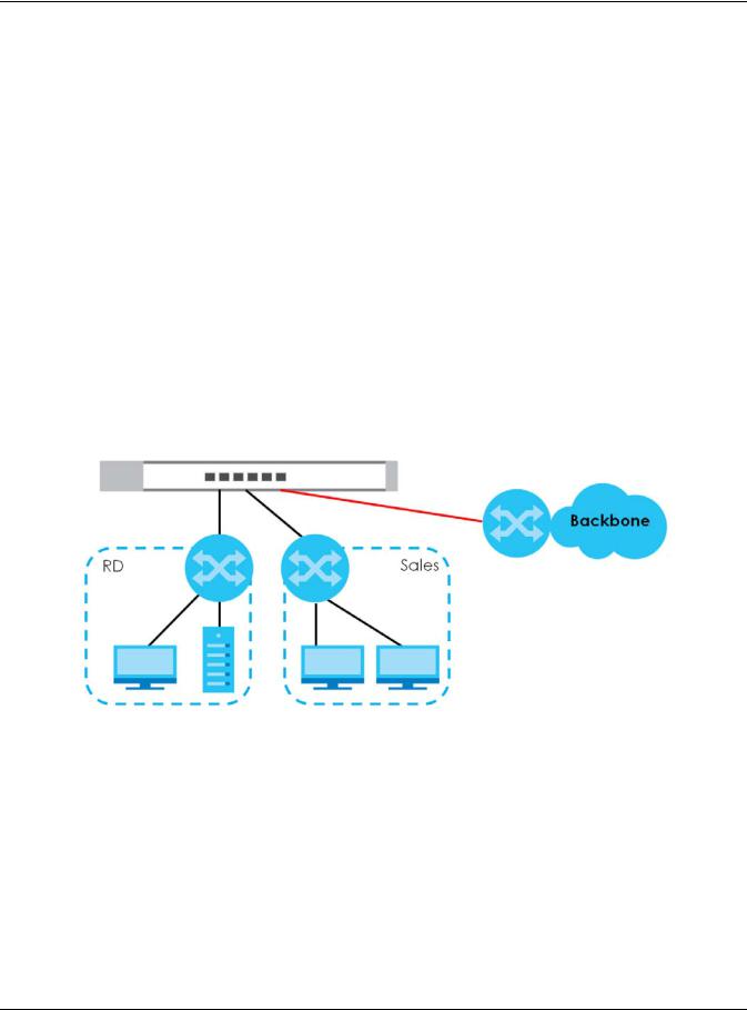
In this example the Switch connects different company departments (RD and Sales) to the corporate backbone. It can alleviate bandwidth contention and eliminate server and network bottlenecks. All users that need high bandwidth can connect to high-speed department servers via the Switch. Figure 1 Bridging Application
1.2.2 VLAN Application Example
A VLAN (Virtual Local Area Network) allows a physical network to be partitioned into multiple logical networks. Stations on a logical network belong to one or more groups. With VLAN, a station cannot directly talk to or hear from stations that are not in the same group(s) unless such traffic first goes through
arouter.
1.2.2.1Tag-based VLAN Example
Ports in the same VLAN group share the same frame broadcast domain, thus increasing network performance by reducing broadcast traffic. VLAN groups can be modified at any time by adding, moving or changing ports without any re-cabling.
GS1200 Series User’s Guide
10
![]()
Chapter 1 Getting to Know Your Switch
Shared resources such as a server can be used by all ports in the same VLAN as the server. In the following figure only ports that need access to the server need to be part of VLAN1. Ports can belong to other VLAN groups too.
Figure 2 Shared Server Using VLAN Example
1.3 Ways to Manage the Switch
Use any of the following methods to manage the Switch.
•Web Configurator. This allows easy Switch setup and management using a (supported) web browser. See Chapter 4 on page 16.
1.4Good Habits for Managing the Switch
Do the following things regularly to make the Switch more secure and to manage the Switch more effectively.
•Change the password. Use a password that’s not easy to guess and that consists of different types of characters, such as numbers and letters.
•Write down the password and put it in a safe place.
•Back up the configuration (and make sure you know how to restore it). Restoring an earlier working configuration may be useful if the device becomes unstable or even crashes. If you forget your password, you will have to reset the Switch to its factory default settings. If you backed up an earlier configuration file, you would not have to totally re-configure the Switch. You could simply restore your last configuration.
GS1200 Series User’s Guide
11

CHAPTER 2
Hardware Installation
2.1 Installation Scenarios
This chapter shows you how to install and connect the Switch.
The Switch can be placed on a desktop. Use the rubber feet in a desktop installation.
2.2 Desktop Installation Procedure
1Make sure the Switch is clean and dry.
2Set the Switch on a smooth, level surface strong enough to support the weight of the Switch and the connected cables. Make sure there is a power outlet nearby.
3Make sure there is enough clearance around the Switch to allow air circulation and the attachment of cables and the power cord.
Note: Make sure you are using the correct type of Ethernet cable (Category 5e, 6UTP/STP, or better Ethernet cable).
GS1200 Series User’s Guide
12

CHAPTER 3
Hardware Panels
This chapter describes the front panel and rear panel of the Switch and shows you how to make the hardware connections.
3.1 Front Panel
The following figures show the front panels of the Switch.
Figure 3 Front Panel: GS1200-5
Figure 4 Front Panel: GS1200-5HP v2
Figure 5 Front Panel: GS1200-8
Figure 6 Front Panel: GS1200-8HP v2
3.2 Rear Panel
The following figures show the rear panels of the Switch.
Figure 7 Rear Panel: GS1200-5
GS1200 Series User’s Guide
13
Chapter 3 Hardware Panels
Figure 8 Rear Panel: GS1200-5HP v2
Figure 9 Rear Panel: GS1200-8
Figure 10 Rear Panel: GS1200-8HP v2
3.2.1 Power Connector
Note: Make sure you are using the correct power source as shown on the panel.
To connect power to the Switch, insert the female end of the power cord to the AC power receptacle on the rear panel. Connect the other end of the supplied power cord to a power outlet. Make sure that no objects obstruct the airflow.
GS1200 Series User’s Guide
14

Chapter 3 Hardware Panels
3.3 LEDs
After you connect the power to the Switch, view the LEDs to ensure proper functioning of the Switch and as an aid in troubleshooting.
Table 2 LED Descriptions
|
LED |
COLOR |
STATUS |
DESCRIPTION |
|
PWR/SYS |
Green |
On |
The system power is on. |
|
Blinking |
The system is starting up. |
||
|
Off |
The system power is off. |
||
|
LINK/ACT |
Amber (10/100 |
On |
The port has a successful 10/100 Mbps or 1000 Mbps connection. |
|
Mbps) |
|||
|
Blinking |
The system is transmitting data through the port. |
||
|
Green (1000 |
|||
|
Blinking |
If you enable Loop Detection in the Port screen, the port in a loop |
||
|
Mbps) |
once a |
state will blink fast. |
|
|
second |
If you enable Loop Prevention in the Port screen, all ports will blink |
||
|
fast. Later, the port in a loop state will be off. If a loop happens |
|||
|
on two ports, all ports will blink fast. Later, the higher-numbered |
|||
|
port will be off. |
|||
|
Off |
The port is disconnected or disabled. |
||
|
If you enable Loop Prevention in the Port screen, and a loop |
|||
|
happens on two ports, the higher-numbered port will be off. |
|||
|
PoE |
Green |
On |
PoE is enabled and power is supplied to the connected PoE- |
|
(GS1200-5HP |
enabled device. |
||
|
Off |
PoE is disabled or power is not being supplied. |
||
|
v2 & GS1200- |
|||
|
8HP v2) |
|||
|
PoE Max |
Amber |
On |
More than 50W has been supplied to the PoE-enabled devices, |
|
(GS1200-5HP |
and the PoE power output is approaching the power budget. |
||
|
v2 & GS1200- |
|||
|
8HP v2) |
|||
|
Off |
Less than 50W has been supplied to the PoE-enabled devices. |
||
GS1200 Series User’s Guide
15

CHAPTER 4
The Web Configurator
4.1 Overview
This section introduces the configuration and functions of the web configurator.
The web configurator is an HTML-based management interface that allows easy Switch setup and management via Internet browser. Use Internet Explorer 10.0 and later versions, Mozilla Firefox 46.0.1 and later versions, or Google Chrome 50.0 and later versions. The recommended screen resolution is 1024 by 768 pixels.
In order to use the web configurator you need to allow:
•Web browser pop-up windows from your device.
•JavaScript (enabled by default).
•Java permissions (enabled by default).
4.2System Login
1Start your web browser.
2Type “http://” and the IP address of the Switch (for example, the default management IP address is 192.168.1.3) in the Location or Address field. Press [ENTER]. Your computer must be in the same subnet in order to access this website address.
3The login screen appears. The default password is 1234. Figure 11 Web Configurator: Login
4The following screen displays if you log into the Switch for the first time. Enter a new password, retype it to confirm and click Apply to view the first web configurator screen. Note that you can enter the default password 1234 again, if you don’t want to change your password.
GS1200 Series User’s Guide
16
Chapter 4 The Web Configurator
Figure 12 Web Configurator: Login
4.3 The Web Configurator Layout
The System screen is the first screen that displays when you access the web configurator.
This guide uses GS1200-5HP v2 screens as an example. The screens may vary slightly for different models. The following figure shows the navigating components of a web configurator screen.
GS1200 Series User’s Guide
17

Chapter 4 The Web Configurator
Figure 13 Web Configurator Layout
A B 
A — Click the menu items to open the screen in the main window.
B — Click this link to log out of the web configurator.
The following table describes the links in the navigation panel.
Table 3 Navigation Panel Links
|
LINK |
DESCRIPTION |
|
|
System |
This link takes you to a screen that displays general system information, PoE status, and |
|
|
individual port statistics. |
||
|
Port |
This link takes you to a screen to enable Broadcast Storm Control and Loop Prevention/Loop |
|
|
Detection. You can also configure advanced settings, such as transmission speed, flow control, |
||
|
and PoE on a port. |
||
|
VLAN |
This link takes you to a screen where you can configure VLAN settings. |
|
|
Link Aggregation |
This link takes you to screens where you can logically aggregate physical links to form one |
|
|
logical and higher-bandwidth link. |
||
|
Mirroring |
This link takes you to a screen where you can copy traffic from one port or ports to another port |
|
|
so that you can examine the traffic from the first port without interference. |
||
|
QoS |
This link takes you to a screen where you can configure port-based or IEEE 802.1p QoS. |
|
|
GS1200 Series User’s Guide |
18
|
Chapter 4 The Web Configurator |
||
|
Table 3 Navigation Panel Links (continued) |
||
|
LINK |
DESCRIPTION |
|
|
IGMP Snooping |
This link takes you to a screen where you can configure IGMP snooping. |
|
|
Management |
This link takes you to screens where you can change the system login password, perform |
|
|
firmware upgrade and configuration file maintenance as well as reboot the system. You can |
||
|
also configure the IP address and subnet mask. |
||
4.3.1 Change Your Password
After you log in for the first time, it is recommended you change the default administrator password. Click Management to display the next screen to change your login password.
Figure 14 Change Administrator Login Password
4.4 Switch Lockout
You could block yourself (and all others) from managing the Switch if you do one of the following:
1Remove all ports from VLAN1 and you do not configure other VLAN groups.
2Forget the password and/or IP address.
GS1200 Series User’s Guide
19

Chapter 4 The Web Configurator
3You forgot to log out of the Switch from a computer before logging in again on another computer.
Note: Be careful not to lock yourself and others out of the Switch.
4.5Resetting the Switch
If you forget the administrator password or cannot access the Web Configurator, you will need to use the Reset button at the front panel of the device to reset the Switch back to the factory defaults.
This means that you will lose all configurations that you had previously and the password will be reset to “1234”. IP address will also be reset to 192.168.1.3
1Make sure the PWR/SYS LED is on (not blinking).
2To set the device back to the factory default settings, press the Reset button for ten seconds or until the PWR/SYS LED begins to blink and then release it. When the PWR/SYS LED begins to blink, the defaults have been restored and the device restarts.
4.6Logging Out of the Web Configurator
Click the Logout icon in a screen to exit the web configurator. You have to log in with your password again after you log out. This is recommended after you finish a management session for security reasons.
GS1200 Series User’s Guide
20
![]()
CHAPTER 5
Initial Setup Example
5.1 Overview
This chapter shows how to set up the Switch for an example network.
The following lists the configuration steps for the initial setup:
•Creating a VLAN
•Setting Port VID
•Power over Ethernet (PoE) Configuration
5.1.1Creating a VLAN
VLANs confine broadcast frames to the VLAN group in which the port(s) belongs. You can create a VLAN group with fixed port members to do this.
In this example, you want to configure port 1 as a member of VLAN 2.
Figure 15 Initial Setup Network Example: VLAN
1 Click VLAN in the navigation panel and click the Create New VLAN button.
GS1200 Series User’s Guide
21
 Loading…