Carel
Электронные компактные контроллеры Carel серии mC2SE для управления холодильными установками и тепловыми насосами в системах вида воздух/воздух, воздух/вода, вода/вода, а также конденсаторами. Руководство по эксплуатации.
Скачать
Pdf 1.74 Mb
Язык: RU
Посмотреть инструкция для Carel µC2 SE бесплатно. Руководство относится к категории без категории, 1 человек(а) дали ему среднюю оценку 9. Руководство доступно на следующих языках: русский. У вас есть вопрос о Carel µC2 SE или вам нужна помощь? Задайте свой вопрос здесь
Не можете найти ответ на свой вопрос в руководстве? Вы можете найти ответ на свой вопрос ниже, в разделе часто задаваемых вопросов о Carel µC2 SE.
Инструкция Carel µC2 SE доступно в русский?
Да, руководствоCarel µC2 SE доступно врусский .
Не нашли свой вопрос? Задайте свой вопрос здесь
MCH2_SE
Общие характеристики
В рамках семейства µc2 компания Carel представляет параметрические контроллеры для управления холодильными машинами/тепловыми насосами с одним и двумя контурами. Все контроллеры семейства μC2SE оснащаются микропроцессором по технологии RISC и платами часов реального времени (опция), что в сумме обеспечивает выдающиеся рабочие характеристики и удобное управление. Контроллеры серии µC2 SE рассчитаны под врезной монтаж и подсоединяются кабелями с разъемами Molex®, что существенно повышает простоту и скорость монтажа, а также экономит свободное пространство.
Контроллеры серии µC2 SE предназначены для управления холодильными машинами/тепловыми насосами (типа воздух-вода и вода-вода), конденсаторными установками, установками типа воздух-воздух (прямо- и противоточными), крышными агрегатами с управлением температурой естественного охлаждения. Контроллеры могут управлять системами, насчитывающими до четырех герметичных или двух полугерметичных компрессоров, до двух контуров с одним электронным терморегулирующим вентилем (ТРВ) на каждый контур.
Преимущества
- Применение электронного терморегулирующего вентиля (ТРВ) обеспечивает точное регулирование температуры перегрева на всасывании, гарантируя более высокую энергоэффективность во всех условиях нагрузки и климатических условиях.
- Широкий выбор графических терминалов, обеспечивающих простой и удобный процесс управления контроллерами семейства µC.
Документация
Technical
-
2D/3D модели
Код Описание Язык Дата * Выпуск Код
2d — 3d mChiller2Описание
Язык
ALLДата
22/01/2019
Выпуск
R0
-
Инструкции по применению
Код Описание Язык Дата * Выпуск Код
+030220425Описание
μC2SE: controllo elettronicoЯзык
ITAДата
08/07/2019
Выпуск
2.6
Код
+030220426Описание
μC2SE: electronic controlЯзык
ENGДата
08/07/2019
Выпуск
2.6
Код
+030220427Описание
μC2SE: contrôle électroniqueЯзык
FREДата
08/07/2019
Выпуск
2.6
Код
+030220428Описание
μC2SE: Elektronische SteuerungЯзык
GERДата
08/07/2019
Выпуск
2.6
Код
+030220429Описание
μC2SE: Электронное управлениеЯзык
RUSДата
08/07/2019
Выпуск
2.6
Код
+030220424Описание
μC2SE: Controlador electrónicoЯзык
SPAДата
08/07/2019
Выпуск
2.6
Код
+030220415Описание
μC2SE per chiller di processo: Controllo elettronicoЯзык
ITAДата
17/05/2018
Выпуск
2.3
Код
+030220416Описание
μC2SE for process chiller: Electronic controllerЯзык
ENGДата
17/05/2018
Выпуск
2.3
Код
+03C220426Описание
μC2SE 电子控制器Язык
CHIДата
27/11/2012
Выпуск
2.5
Код
+030220422Описание
μC2SE: elektronický regulátorЯзык
CZEДата
27/11/2012
Выпуск
2.5
-
Руководства по эксплуатации
Код Описание Язык Дата * Выпуск Код
+050002815Описание
MCH200*03 — μC2SE: Dispositivo elettronico per controllo di chiller a 2/4 compressori (mono e bicircuito) / Electronic controller for chillers with 2/4 compressors (one and two circuits)Язык
ENG
ITAДата
03/08/2009
Выпуск
1.1
Код
+050002818Описание
MCH200*03 — μC2SE: Electronic controller for chillers with 2/4 compressors (one and two circuits) / Электронный контроллер для чилеров с 2/4 компрессорами (1 и 2 контура)Язык
ENG
RUSДата
03/08/2009
Выпуск
1.1
Код
+05C002815Описание
MCH200*03 — μC2SE: 用于带2/4压缩机的冷水机组(一个或两个回路) 控制器/ Electronic controller for chillers with 2/4 compressors (one and two circuits)Язык
CHI
ENGДата
05/08/2005
Выпуск
1.0
Commercial
-
Брошюра
Код Описание Язык Дата * Выпуск Код
+302239461Описание
Integrated solutions for ground source heat pumpsЯзык
ENGДата
01/03/2008
Выпуск
2.0
Код
+30C239461Описание
地源热泵系统控制 的整体解决方案Язык
CHIДата
01/03/2008
Выпуск
2.0
Код
+302239450Описание
Soluzioni integrate per rooftopЯзык
ITAДата
01/10/2006
Выпуск
1.0
Код
+302239451Описание
Integrated solutions for rooftop unitsЯзык
ENGДата
01/10/2006
Выпуск
1.0
Код
+302239470Описание
Soluzioni integrate per impianti idronici medio piccoliЯзык
ITAДата
01/10/2006
Выпуск
1.0
Код
+302239471Описание
Integrated solutions for small and medium hydronic systemsЯзык
ENGДата
01/10/2006
Выпуск
1.0
Код
+302239473Описание
Integrierte Lösungen für kleine und mittlere Hydronic-AnlagenЯзык
GERДата
01/10/2006
Выпуск
1.0
Код
+302239361Описание
Integrated solutions for large chillers/heat pumpsЯзык
ENGДата
01/03/2006
Выпуск
1.0
Код
+302239365Описание
Soluzioni integrate per chiller e pompe di calore di media e piccola tagliaЯзык
ITAДата
01/03/2006
Выпуск
1.0
Код
+302239366Описание
Integrated solutions for small and medium size chiller/heat pumpsЯзык
ENGДата
01/03/2006
Выпуск
1.0
Код
+302239369Описание
Комплексные решения для чиллеров/тепловых насосов малого и среднего размераЯзык
RUSДата
01/03/2006
Выпуск
1.0
Код
+302239360Описание
Soluzioni integrate chiller e pompe di calore di grossa tagliaЯзык
ITAДата
01/03/2006
Выпуск
1.0
Код
+30C239611Описание
μC sistema: 系列Язык
CHIДата
01/10/2005
Выпуск
1.0
Код
+302239611Описание
μC sistema: the rangeЯзык
ENGДата
01/10/2005
Выпуск
1.0
Код
+302239613Описание
μC sistema: Die ProduktbandbreiteЯзык
GERДата
01/10/2005
Выпуск
1.0
-
История успеха
Код Описание Язык Дата * Выпуск Код
+402200110Описание
Development of an advanced control system for chillersЯзык
ENGДата
01/03/2006
Выпуск
1.0
- Холодильное оборудование
- Контроллеры


| Артикул | MCH2001030 |
| id товара | 8659 |
| Страна | Италия  |
| Минимальный заказ | 1 шт |
| В наличии на складах | 0 шт |
Общее описание
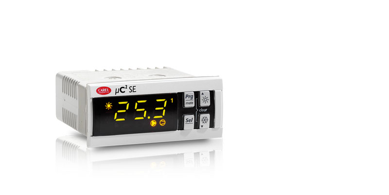
Контроллер Carel MCH2001030 (mC2SE) — предназначен для управления чиллером, тепловым насосом, конденсаторами и установками воздух/воздух с одним контуром и 2 герметичными компрессорами. Имеет компактные размеры и встроенный пользовательский интерфейс. Возможности наращиваются за счет применения дополнительных модулей Например присоединение платы расширения позволяет управлять чиллером с 2 контурами и до 4-х компрессоров. В стандартном исполнении имеет 5 реле для управления компрессором, нагревателем или реверсивным клапаном, вентилятором/насосом испарителя, компрессором №2 или регулировка производительности компрессора №1, аварийной сигнализацией или реверсивным клапаном. Напряжение питания 24В переменного тока 50/60Гц.
Технические
характеристикиЧертежи
и схемыДополнительная
информация
Характеристика
| Производитель | Carel |
| Назначение | Для чиллеров |
| Количество релейных выходов | 5 |
| Напряжение питания | 24 V |
| Подключение к мониторингу | Требуется карта |
Чертежи


Дополнительная информация
Руководство пользователя mC2SE (0.98Mb)
Сервис мануал mC2SE (2.65Mb)
Полезные ссылки
Сайт производителя Carel
-
Page 1: User Manual
µC electronic control User manual…
-
Page 3
CAREL or its branch offi ces/affi liates have been warned of the possibility of damage. -
Page 4
µC SE — +030220426 — rel. 2.0 — 03.08.2009… -
Page 5: Table Of Contents
Content ONTENT 1. INTRODUCTION 1.1 General description ……………………..7 1.2 User interface ……………………….7 2. CONNECTIONS 2.1 General diagram ………………………9 2.2 Network layout ………………………..9 3. APPLICATIONS 3.1 Air/air unit …………………………10 3.2 AIR/AIR heat pump ……………………..11 3.3 AIR/WATER chiller ……………………..13 3.4 AIR/WATER heat pump ……………………14 3.5 WATER/WATER chiller …………………….16 3.6 WATER/WATER heat pump with reversal on gas circuit …………..17 3.7 WATER/WATER heat pump with reversal on water circuit …………19…
-
Page 6
µC SE — +030220426 — rel. 2.0 — 03.08.2009… -
Page 7: Introduction
• antifreeze heater; • alarm signal device. 1.1.3 Programming CAREL offers the possibility to confi gure all the unit parameters not only from the keypad on the front panel, but also using: • a hardware key; • a serial line.
-
Page 8
1.2.3 Functions associated with the buttons button unit status button press Loading default values press at power ON Go up a sub-group inside the programming area, until exiting (saving changes to EEPROM) press once In the event of alarms, mute the buzzer (if present) and deactivate the alarm relay press once Access the direct parameters press for 5 s… -
Page 9: Connections
µ expansion valve valve Optional board PSOPZKEY*: programming key CONVONOFF*: PWM/digital converter PW/Modbus ® CONV0/10A0*: PWM/analogic CAREL Supervisory MCH200485* converter NTC: temperature RS485 MCH2*T*: probes serial card terminal MCHRTF**A0: PW/Modbus ® MCH2*TSV*: SPKT: 0 to 5 V fan speed regulator…
-
Page 10: Applications
3. APPLICATIONS 3.1 Air/air unit 3.1.1 Single circuit Key: condernser fan overload condenser probe supply probe electrical heater evaporator supply fan overload supply fan compressor 1 high pressure compressor overload low pressure ambient probe compressor 2 Fig. 3.a.a 3.1.2 Two circuits Key: condernser fan overload 1 and 2 condenser probe…
-
Page 11: Air/Air Heat Pump
3.1.2 Two circuits, 1 condenser fan circuit Key: condernser fan overload condenser probe 1 and 2 supply probe electrical heater 1 and 2 evaporator 1 and 2 supply fan ambient probe compressor 1 high pressure 1 and 2 compressor overload 1 and 2 low pressure 1and 2 compressor 2 compressor 3…
-
Page 12
3.2.2 Two circuits Key: condenser fan overload 1 and 2 condernser probe supply probe electrical heater 1 e 2 evaporator 1 and 2 supply fan overload supply fan compressor 1 high pressure 1 e 2 compressor overload 1 and 2 low pressure 1and 2 ambient probe compressor 2… -
Page 13: Air/Water Chiller
3.3 AIR/WATER chiller 3.3.1 Single circuit Key: condernser fan overload condenser probe fl ow switch outlet evaporator probe antifreeze heater inlet evaporator probe compressor 1 high pressure compressor overload low pressure water pump compressor 2 Fig. 3.c.a 3.3.2 two circuits, 2 condenser fan circuits and 2 evaporators Key: condenser fan overload 1 and 2 fan 1 and 2…
-
Page 14: Air/Water Heat Pump
3.3.2 two circuits, 1 condenser fan circuit Key: condenser fan overload condenser probe 1 and 2 fl ow switch outlet temperature probe evaporator 1 and 2 outlet evaporator probe 1 and 2 antifreeze heater 1 and 2 compressor 1 high pressure 1 and 2 compressor overload 1 and 2 low pressure 1and 2 inlet evaporator probe…
-
Page 15
3.4.2 2 condenser fan circuits Key: condenser fan overload 1 and 2 fan 1 and 2 condenseer probe 1 and 2 fl ow switch outlet temperature probe evaporator 1 and 2 outlet evaporator probe 1 and 2 antifreeze heater 1 and 2 compressor 1 high pressure 1 and 2 compressor overload 1 and 2… -
Page 16: Water/Water Chiller
3.5 WATER/WATER chiller 3.5.1 Single circuit Key: water condensing temperature probe condensator fl ow switch outlet evaporator probe evaporator antifreeze heater inlet evaporator probe compressor 1 high pressure compressor overload low pressure water pump compressor 2 Fig. 3.e.a 3.5.2 Two circuits Key: water condensing temperature probe 1 and 2 condensator 1 and 2…
-
Page 17: Water/Water Heat Pump With Reversal On Gas Circuit
3.5.3 Ttwo circuits, 2 evaporators Key: water condensing temperature probe 1 and 2 condensator 1 and 2 fl ow switch outlet temperature probe outlet evaporator probe 1 and 2 antifreeze heater 1 and 2 evaporator water pump compressor 1 high pressure 1 and 2 compressor overload 1 and 2 low pressure 1 and 2 compressor 3…
-
Page 18
3.6.2 Two circuits Key: water condensing temperature probe 1 and 2 condensator 1 and 2 fl ow switch outlet evaporator probe outlet evaporator probe 1 and 2 evaporator 1 and 2 antifreeze heater 1 and 2 water pump compressor 1 high pressure 1 and 2 compressor overload 1 and 2 low pressure 1 and 2… -
Page 19: Water/Water Heat Pump With Reversal On Water Circuit
3.7 WATER/WATER heat pump with reversal on water circuit 3.7.1 Single circuit Key: external internal reversing valve fl ow switch outlet evaporator probe antifreeze heater evaporator condenser condenser probe compressor 1 high pressure compressor overload low pressure water pump compressor 2 12 13 Fig.
-
Page 20: Air-Cooled Condensing Unit Without Reverse Cycle
3.7.3 Two circuits, 1 evaporator H02= 1 e H21= 4 Key: external internal reversing valve 1 and 2 condenser probe fl ow switch outlet evaporator probe condenser probe 1 and 2 condenser 1 and 2 outlet evaporator probe 1 and 2 antifreeze heater 1 and 2 evaporator 1 and 2 compressor 1…
-
Page 21: Reverse-Cycle Air-Cooled Condensing Unit
3.8.2 Two circuits Key: condenser fan overload condenser probe compressor 1 high pressure 1 and 2 compressor overload 1 and 2 low pressure 1 and 2 compressor 2 compressor 3 compressor 4 Fig. 3.h.b 3.9 Reverse-cycle air-cooled condensing unit 3.9.1 Single circuit Key: condenser fan overload condenser probe…
-
Page 22: Water-Cooled Condensing Unit Without Reverse Cycle
3.9.2 Two circuits with one condenser fan circuit Key: condenser fan overload condenser probe compressor 1 high pressure 1 and 2 compressor overload 1 and 2 low pressure 1 and 2 compressor 2 compressor 3 compressor 4 reversing valve Fig. 3.i.b 3.10 Water-cooled condensing unit without reverse cycle 3.10.1 Single circuit Key:…
-
Page 23: Reverse-Cycle Water-Cooled Condensing Unit
3.10.2 Two circuits Key: fl ow switch water cond. temperature probe condenser compressor 1 high pressure compressor overload lw pressure compressor 2 compressor 3 compressor 4 water pump Fig. 3.j.b 3.11 Reverse-cycle water-cooled condensing unit 3.11.1 Single circuit Key: condenser probe condenser antifreeze heater compressor 1…
-
Page 24: Roof Top Units
3.11.2 Two circuits Key: condenser probe condenser 1 and 2 antifreeze heater 1 and 2 reversing valve compressor 1 high pressure 1 and 2 compressor overload 1 and 2 low pressure 1 and 2 compressor 3 compressor 2 compressor 4 water pump Fig.
-
Page 25: Parameters
4. PARAMETERS 4.1 General parameters The parameters are divided into 4 different types, according to their level of access by the user (password) and their function. For each level, only the access to the parameters of the same or lower level can be set. This means that through “factory”…
-
Page 26: Parameter Tables
4.3 Parameter tables The following tables show of the parameters divided by type/family (e. g. compressor, probes, fans etc.). • Key to the parameter tables Level (default) S= super user F= factory D= direct Visibility: The visibility of some groups depends on the type of controller and the value of the parameters. D= defrost (if D01=1) F= fan (if F01=1) L= low noise (if F15=1-3)
-
Page 27
4.3.3 Antifreeze/support heater setting parameters (A*) display parameter and description default min. max. UOM variat. default visibility supervis. Modbus variable indicat. level variable type Alarm set point antifreeze/low ambient temperature (air/air) °C/°F 11 (R/W) Analog Differential for antifreeze/low ambient temperature alarm (air/air) 1220 °C °F 12 (R/W) -
Page 28
4.3.6 Defrost setting parameters (d*) display parameter and description default min. max. U.O.M. variat. default visibility supervis. Modbus variable indicat. level variable type Defrosting cycle/Condenser antifreeze Flag 7 (R/W) Digital 0= no; 1= sì, con sbrinamento unifi cato yes, with shared defrosting Time-or temperature-based defrosting Flag 90 (R/W) -
Page 29
4.3.8 Unit setting parameters (H*) display parameter and description default min. max. U.O.M. variat. def. visibility supervis. Modbus variable indicat. level variable type Unit model Flag 54 (R/W) Integer 0= air_air unit 1= air_air heat pump 2= air_water chiller 3= air_water heat pump 4= water_water chiller 5= water_water heat pump with reversal on gas circuit 6= water_water heat pump with reversal on water circuit… -
Page 30
4.3.9 Firmware parameters (F-r*) display parameter and description default min. max. U.O.M. variat. default visibility supervis. Modbus variable type indicat. level variable Software version, Driver 2 1 (R) Integer Software version, Driver 1 2 (R) Integer Expansion software version 3 (R) Integer Software version (displayed when powering up the 4 (R) -
Page 31
4.3.11 Control setting parameters (r*) display parameter and description default min. max. U.O.M. variat. def. visibility supervis. Modbus variable indicat. level variable type Cooling set point °C/°F 12.0 41 (R/W) 41 Analog Cooling differential °C/°F 42 (R/W) 42 Analog Heating set point °C/°F 43 (R/W) 43 Analog… -
Page 32
4.3.12 Timer setting parameters (t*) display parameter and description default min. max. U.M. variat. def. visibility supervis. Modbus variabile type indicat. level variable RTC hours 129(R/W) Integer RTC minutes 130 (R/W) Integer RTC day 131 (R/W) Integer RTC month mesi 132 (R/W) Integer RTC year… -
Page 33
U.O.M. variat. def. visibility supervis. Modbus variable indicat. level variable type Indicates the unit parameter (Carel SV communication) Integer Gain constant for pressure probe calibration 16000 1000 Integer Offset constant for pressure probe calibration -8000 8000 Integer… -
Page 34
Communication of the logical status of the digital outputs to 4200 Integer expansion: bit0= compressor bit1= compressor 4 bit2= heater 2 bit3= reversing valve bit4= warning bit5= condenser pump bit6= fans in alarm status bit7= fan status in alarm (ON= 1; ofF= 0) bit8= speed to be set (100%= 1;… -
Page 35: Description Of The Parameters
5. DESCRIPTION OF THE PARAMETERS To modify the parameters, see chapter 4 “Parameters.” • Probe settings: parameters (/*) ( see Table 4.a) — Type of probe: from /01 to /08: enables the reading of the corresponding analogue input or sets the function •…
-
Page 36
A05: Differential for the activation and deactivation of the antifreeze heaters (auxiliary heaters in air/air units). CAREL NTC probe (mode H1= 2, 3, 4, 5 and 6) Operating diagram of the antifreeze alarm and the antifreeze heaters for air/water and water/water chillers and heat pumps. -
Page 37
In this case, the display will be as follows: • operating mode LED OFF; • cooling heating fl ag not switched (not detected by the supervisor); • antifreeze alarm A01 (remains active even at the end of the special operation if the unit was previously ON, deactivated by manual reset or in standby). -
Page 38
— Start delay between compressors c04: This sets the delay between the starts of the two compressors, so as to reduce the peak power input and make the compressors start more smoothly. The compressor LED fl ashes in this phase. •… -
Page 39
— Hour counter compressor 1-2-3-4 c10, c11, c12, c13: These indicate the number of operating hours of compressor 1, 2, 3, 4, expressed in hundreds of hours. Pressing together, when the hour counter is displayed, resets the hour counter and, consequently, cancels any maintenance requests in progress. -
Page 40
— Type of defrost d02: establishes the type of defrost. d02=0: the defrost has a fi xed duration that depends on d07 d02=1: the defrost starts and ends according to the temperature or pressure thresholds, see d03 and d04; d02=2: the pressure transducer and temperature probe are both located on the outside exchanger; the defrost starts when the value read by the pressure transducer is below the threshold d03 and ends when the value read by the temperature probe is above the threshold d04;… -
Page 41
d10= 2: end defrost from external contact enabled therefore: • if the contact of the input is open, the end of the defrost is enabled; • if the contact of the input is closed, the defrost follows the normal procedure. d10= 3: start and end defrost from external contact enabled therefore: •… -
Page 42
— Max outside temperature threshold for sliding defrost d18: This establishes the maximum value of the outside temperature below which sliding defrost is activated. — Maximum temperature/pressure differential deviation for defrost d19: This value is expressed in °C if the compensation is controlled by temperature, or in bar if controlled by pressure. -
Page 43
— Maximum voltage threshold for Triac F04: In the event of fan speed control, the optional phase cutting cards (MCHRTF*) are required, fi tted with a triac. The voltage delivered by the triac to the electric fan motor corresponding to the maximum speed must be set. -
Page 44
— Fan management mode in defrost F13: This parameter sets the operating logic for the condensing fans during the defrost phase: F13 = 0: (default) the fans are OFF. F13 = 1: the fans are ON as in cooling mode, based on the temperature or pressure. F13 = 2: the fans are OFF until the end defrost temperature or pressure is reached, above which they are started at maximum speed for the time set for parameter d16. -
Page 45
— Number of evaporators H03: This establishes the number of evaporators present when there are 2 or 4 compressors, obviously with 2 circuits (including the expansion). With one evaporator (H03=0), the management of the heaters and the antifreeze function is performed only on B2. Vice-versa, with 2 evaporators (H03=1) antifreeze control will be performed using B2 and B6, while input B5 is used to control the water outlet temperature. -
Page 46
H11= 12: associated device outputs H11=0 H11= 1 H11= 2 H11= 3 H11= 4 H11= 5 compressor 1 compressor 1 compressor 1 compressor 1 compressor 1 compressor 1 heater 1 heater 1 heater 1 reversing valve 1 reversing valve 1 heater 1 Pump/evaporator (fan) (on air/ Pump/evaporator (fan) (on air/… -
Page 47
— Maximum pumpdown time H15: Maximum time after which the compressor is deactivated. — SmartSET “CAREL patent” (cannot be used on air/air units) H16: Activate smartSET, this function optimises the operation of the unit by calculating the effi ciency of the heat exchangers. -
Page 48
PRG button at power ON. — select supervisor protocol H23: establishes the protocol used for the connection to the supervisor from the serial board RS485 H23 = 0: CAREL protocol (baud rate 19200,…) H23 = 1: Modbus protocol • Alarm settings: parameters (P*) — Flow switch alarm delay when starting pump P01: Establishes a delay in the recognition of the fl… -
Page 49
— Alarm reset P05: Enables automatic reset for all those alarms that normally feature manual reset (high pressure, low pressure, fl ow switch/antifreeze) as per the following table: P05= 0: (default) high pressure, low pressure and antifreeze (low temperature) with manual reset; P05= 1: all the alarms with automatic reset;… -
Page 50
— High temperature alarm delay on power-up P17: High temperature alarm delay when the control is switched on (power ON), from the remote ON/ OFF contact or from the keypad. — High pressure alarm from transducer set point P18: Sets the value beyond which the high pressure alarm is generated. Each circuit will be managed by its own transducer. -
Page 51
When stopping, the valve is managed fi rst and then the actual compressor as a whole. Both FIFO logic and timed operation will involve either one circuit or the other. The activation and deactivation of the valves are not subject to timers, but rather only a hysteresis that is equal to the set point and the differential of the step (in fact the valve performs the same function as a hermetic compressor). -
Page 52
In heating: With autotuning active and inlet control, this represents the delay from switching the compressor off to reach the outlet set point, before the next deactivation. — Compressor deactivation differential (if r06 = 4) r12: This represents the temperature differential for the deactivation of the compressors, according to the procedure described in “Deactivation time”. -
Page 53
— Maximum deviation from the set point r18: Indicates the maximum deviation from the set point beyond which compensation is stopped (maximum and minimum limits in reference to the set point). — Start compensation temperature in cooling (outside probe) r19: Sets the temperature (measured by the outside probe) above which the compensation function starts (cooling), value between -40T80 °C. -
Page 54
— Cooling set point in dehumidifi cation r26: Alternative set point to r01 when the dehumidifi cation function is active, as sent to the µC SE by the terminal. The differential remains the same as for chiller mode (r02). — Buffer tank suppression (low load) r27: The low load condition is determined when only one compressor is started and then is stopped after operating for less than the time set for parameter r28. -
Page 55
— Enable freecooling/freeheating Example of freecooling r34: Sets the type of freecooling/heating with or without compressors r34= 0: disabled r34= 1: freecooling / without compressors / cooling only r34= 2: freecooling / with compressors / cooling only r34= 3: freeheating / without compressors / heating only r34= 4: freeheating / with compressors / heating only r34= 5: freecooling and freeheating / without compressors / freecooling in cooling only and freeheating in heating only… -
Page 56
Duty cycle differential example — Damper opening duty cycle differential r37: used to calculate the duty cycle for opening the damper. — Damper closing duty cycle differential r38: used to calculate the duty cycle for closing the damper. Key: 1. opening time; Fig. -
Page 57
— RTC year t05: RTC year The alarms are only shown on the local display. The controller saves the signifi cant events that stop (alarms) or limit (warnings) the operation of the unit. Up to 25 events can be saved, highlighting: —… -
Page 58: Table Of Alarms
6. TABLE OF ALARMS Key to the table of alarms: *: if the probe is set for the compensation function, in the event of probe faults, the unit continues to operate. ON*: if the expansion card is not present. EVD 1= EVD400 connected to µC SE (1st circ.) EVD 2= EVD400 connected to the expansion (2nd circ.) alarm…
-
Page 59
HP1: High pressure circuit 1 The alarm is detected irrespective of the status of the pump and the compressors. The compressors corresponding to circuit 1 are immediately stopped (ignoring the set protection times), the buzzer and alarm relay are activated, and the display starts fl ashing. The fans corresponding to the condenser in circuit 1 are activated at maximum speed for 60 s, so as to oppose the alarm situation, after which they are switched OFF. -
Page 60
Hc1 to Hc4: compressor operating hour limit exceeded warning When the number of operating hours for the compressor exceeds the maintenance threshold (as default equal to zero, and consequently the function is disabled), the maintenance request signal is activated. The buzzer and the alarm relay are not activated, however the warning relay is activated (with the expansion card fi… -
Page 61
D1: defrost signal circuit 1 When the defrost is on circuit 1, the display shows the message D1. D2: defrost signal circuit 2 When the defrost is on circuit 2, the display shows the message D2. Fd: dirty fi lter warning This warning is only shown if the temperature difference between the exchanger inlet and outlet is higher than parameter A12. -
Page 62: Connections, Accessories And Options
7. CONNECTIONS, ACCESSORIES AND OPTIONS 7.1 Connection diagram Below is the connection diagram for the µC Panel version EV driver EV driver Line Expansion EV Driver board EV Driver tLAN No1 C1/2 C1/2 C3/4 x N02 No3 No4 C3/4 x No5 Tx/Rx GND GND B4 V+ G0 B1 B2 B3 ID5 ID3 ID1…
-
Page 63: Expansion Card
7.2 Expansion card This device allows the µC SE to manage the second refrigerant circuit on chillers, heat pumps and condensing units with up to 4 hermetic compressors. The following fi gure shows the connection diagram for the µC SE expansion card, code MCH200002*. EV Driver Line EV driver…
-
Page 64: Fan Speed Control Board (Code Mchrtf*)
7.4 Fan speed control board (code MCHRTF*) The phase cutting boards (code MCHRTF****) are used to control the speed of the condenser fans. IMPORTANT: The power supply to the µC SE (G and G0) and the MCHRTF**** board must be in phase.
-
Page 65: Programming Key (Code Psopzkeya0)
Warning: the copying of the parameters is allowed only between instruments with the same code. Data loading operation to the key is always allowed. To make identifi cation of the key easier CAREL has inserted a label on which you can describe the loaded programming or the machine to which you are Fig.
-
Page 66: Rs485 Serial Options
7.9 RS485 serial options RS485 serial option for µC SE panel version (code MCH2004850) The MCH2004850 serial option is used to connect the µC SE controller to a supervisor network via a standard RS485 serial line. This option uses the input normally associated with the programming key, which has the dual function of key connector/serial communication port.
-
Page 67: Dimensions
8. DIMENSIONS The following are the mechanical dimensions of each component in the µC SE controller; all the values are expressed in millimetres. Note: the dimensions include the free connectors inserted. MCH200000* µC SE panel mounting version drilling template 71×29 mm com p x10 0 panel mounting…
-
Page 68
MCHRTF series single-phase speed controllers Model A (component side) B MCHRTF04C0 MCHRTF08C0 MCHRTF12C0 Note: the version with screw teminals code MCHRTF*D0 is available on request Table 8.a 8 e 12 A Fig. 8.e Model MCHRTF10C0 Table 8.b 74.5 12.5 Ø 4 74.5 12.5 Fig. -
Page 69: Codes
B1, B2, B3, B4: NTC CAREL temperature probes (10 kW at 25 °C) Fig. 10.a The response time depends on the component used, typical value 90 s B4: NTC temp. probes (10 kW at 25 °C) or CAREL 0 to 5 V ratiometric pressure probes SPKT00**R* Fan output…
-
Page 70: Software Updates
The error in the converted value may vary according to the settings of parameters /9, /10, /11, /12 Table 10.b Characteristics of the connectors The connectors may be purchased using CAREL code (MCHCON0***) or from the manufacturer Molex ® Molex ®…
-
Page 72
Agence/Agency: CAREL INDUSTRIES HQs Via dell’Industria, 11 — 35020 Brugine — Padova (Italy) Tel. (+39) 049.9716611 — Fax (+39) 049.9716600 e-mail: carel@carel.com — www.carel.com…