-
Contents
-
Table of Contents
-
Troubleshooting
-
Bookmarks
Quick Links
MAKING MODERN LIVING POSSIBLE
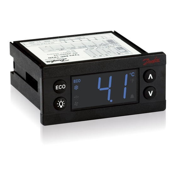
ERC 102 refrigeration controller
Reference manual
This reference manual is intended to be used primarily by OEMs for the purposes of programming ERC 102.
It may also be useful for technicians. It is not intended as a user guide for end users.
www.danfoss.com/erc
Related Manuals for Danfoss ERC 102
Summary of Contents for Danfoss ERC 102
-
Page 1
ERC 102 refrigeration controller Reference manual This reference manual is intended to be used primarily by OEMs for the purposes of programming ERC 102. It may also be useful for technicians. It is not intended as a user guide for end users. -
Page 2: Table Of Contents
Set lighting function . . . . . . . . . . . . . . . . . . . . . . . . . . . . . . . . . . . . . . . . . . . . . . . . . . 23 ERC 102 Reference manual…
-
Page 3
ERC102 Application Matrix . . . . . . . . . . . . . . . . . . . . . . . . . . . . . . . . . . . . . . . . . . . . . . 60 ERC 102 Reference manual… -
Page 4: Introduction
. Three separate password-protected user levels can be used to control more than 200 different parameters to fit all individual requirements . ERC 102’s IP rated body, advanced materials and internationally approved hardware design open it up for use in almost any climate globally, indoors as well as outdoors .
-
Page 5: Content Of The Box
. For detailed mounting instructions, please contact your local Danfoss representative . NOTE: This sensor is not included in the sample box . Defrost sensors can also be used as condenser sensors. ERC 102 Reference manual – 2 CONTENT OF THE BOX…
-
Page 6
. They are not used with front mounting . There are two identical clips, one placed on either side of the ERC 102 . See Chapter 4 – Mounting – for further details . ERC 102 Reference manual – 2 CONTENT OF THE BOX… -
Page 7: Connections
KoolProg: is the software from Danfoss for programming the ERC 102 via a USB cable and a PC rather than with the front panel buttons . Please refer to the KoolProg manual for details . ERC 102 Reference manual – 2 CONTENT OF THE BOX…
-
Page 8: Overview Of The Product
The ERC 102 is a state-of-the art, IP65 (front)-rated refrigeration controller for use in both Glass Door The ERC 102 can also be programmed via USB using Merchandising and Commercial Fridges and Freezer the Danfoss KoolProg software, allowing the most applications .
-
Page 9: Connector Outputs
Please refer to the code number specific technical drawing or use the KoolProg infor- mation menu. For other applications, a condenser sensor and a door sensor may be used. ERC 102 Reference manual – 3 OVERVIEW OF THE PRODUCT…
-
Page 10: Mounting
4.1 Rear mounting – Option 1 1 . Insert the ERC 102 into the cabinet . 2 . Attach the clips to each side of the ERC 102 . 3 . Place the front frame on to the ERC 102 and click it into place .
-
Page 11: Unmounting
1 . Disconnect the power cable and then the sensors . 2 . Use a flat head screwdriver (ideally the one supplied with the ERC 102 sample package) and insert it carefully between the front frame and the controller .
-
Page 12: Front Mounting — Option 2
– parameters for information about programming which inputs and outputs are applicable to your configuration) . 2 . Insert the ERC 102 into place in the cabinet . 3 . Press the front frame into place – this locks the ERC 102 into position .
-
Page 13: Unmounting
4.2.1 Unmounting 1 . Use a flat head screwdriver (ideally the one supplied with the ERC 102 sample package) and insert it carefully between the front frame and the controller . 2 . Gently twist the screwdriver to remove the front frame .
-
Page 14: Controlling/Navigation
1 Click: Temperature setpoint Hold 3 sec: Menu Sub function: Down 1 Press: Variable direct function, e.g. light 1 Press: Temperature setpoint Sub function: OK Sub function: OK Sub function: Down ERC 102 Reference manual – 5 CONTROLLING / NAVIGATION AND ACCESS LEVELS…
-
Page 15: Direct Functions For Access
1 Click: Temperature setpoint Sub function: Down The green ECO symbol is lit when in ECO mode rect function, e.g. light 1 Click: Temperature setpoint Sub function: Down ERC 102 Reference manual – 5 CONTROLLING / NAVIGATION AND ACCESS LEVELS…
-
Page 16: Operating The Menu
Some parameters may be hidden to you. When scrolling through menus, the parameters available will have been pre-determined using KoolProg software. Your access level will determine which parameters you can view and edit. ERC 102 Reference manual – 5 CONTROLLING / NAVIGATION AND ACCESS LEVELS…
-
Page 17
Hold 3 sec: Menu Sub function: Down Sub function: OK 1 Click: Variable direct function, e.g. light 1 Click: Temperature setpoint Hold 3 sec: Menu Sub function: Down Sub function: OK ERC 102 Reference manual – 5 CONTROLLING / NAVIGATION AND ACCESS LEVELS… -
Page 18: Menu Structure
Level 3: OEM (OEM programming) Hold 3 sec: Menu Hold 3 sec: Menu Sub function: Down Sub function: Down Sub function: Down Sub function: OK Sub function: OK ERC 102 Reference manual – 5 CONTROLLING / NAVIGATION AND ACCESS LEVELS…
-
Page 19: Configuration Of Inputs And Outputs
Example: Input S2 is attached a digital on/off sensor which is a door open / closed switch . Connector inputs: analogue ( a ), digital ( b ) Connector outputs ( c ) ERC 102 Reference manual – 6 CONFIGURATION OF INPUTS AND OUTPUTS…
-
Page 20
— — RW Password level1 RW RW RW Password level2 — — RW Password level3 — — RW Cabinet Light Control — — RW Source Light off delay — — RW ERC 102 Reference manual – 6 CONFIGURATION OF INPUTS AND OUTPUTS… -
Page 21
Pil: Pilot Relay (No Zero Cross) – if using pilot relay to control a compressor, this option must be used instead of CoP Het: Heating application, inverse output . 1 Click: Temperature setpoint Sub function: Down ERC 102 Reference manual – 6 CONFIGURATION OF INPUTS AND OUTPUTS… -
Page 22: Program The Buttons
Your assignments may not be shown on the printed buttons . We advice to use this functionality Sub function: Down together with the fully integrated mounting model only . ERC 102 Reference manual – 6 CONFIGURATION OF INPUTS AND OUTPUTS…
-
Page 23: Set Passwords
. Passwords are entered by using the up and down arrow buttons . 1 Click: Temperature setpoint Danfoss advises against using passwords which are easy to remember or enter, for Sub function: Down example 111, 222, 123 etc .
-
Page 24: Parameters
This chapter details all user-accessible parameters The access level can be set separately for each in ERC 102 software 5 .05 . parameter using KoolProg software . There are three levels of access – 1, 2 and 3 . Level 1 is for shop access,…
-
Page 25
. For instance, at a measured temperature of 7*C and tAd set to -2K, the input from the control sensor will be 5*C instead . ERC 102 Reference manual – 7 PARAMETERS 1 Click: Temperature setpoint Sub function: Down… -
Page 26: Alarm
-50 .0/-58 .0 -50 .0/-58 .0 80 .0/176 .0 C/F a °C/°F — RW RW Pulldown delay — RW RW Door Open delay — RW RW Alarm Buzzer Duration — RW RW Auto Clearance of — RW RW Alarm/Error ERC 102 Reference manual – 7 PARAMETERS…
-
Page 27
Sub function: Up Alarm Buzzer Duration / Abd The ERC 102 alarm sounds for 10 seconds, followed by silence for 50 seconds . One alarm sequence therefore lasts 60 seconds . These values cannot be changed . This parameter determines how long in minutes an audible alarm will continue while there is still a reason to have an alarm . -
Page 28: Compressor
— — RW Maximum voltage — — RW Power On Delay — RW RW Power Factor Degree — — RW Initial cut in — R- RW Compressor door open delay — RO RW ERC 102 Reference manual – 7 PARAMETERS…
-
Page 29
Ert and ESt define the duration the compressor will run (Ert) and be idle (ESt) . Sub function: Down Example: Ert = 4 [min] and ESt = 16 [min] will provide an average cooling system activity of 20% . 1 Click: Temperature setpoint Sub function: Down ERC 102 Reference manual – 7 PARAMETERS… -
Page 30
This parameter sets the delay in minutes before the compressor stops when the door is opened . If set to zero, the function is disabled . 1 Click: Temperature setpoint Sub function: Down ERC 102 Reference manual – 7 PARAMETERS… -
Page 31: Defrost
25 .0/77 .0 -25 .0/13 .0 25 .0/77 .0 C/F a °C/°F — — RW Defrost Fan on — — RW Initial Defrost Interval hour — — RW Initial Defrost Duration — RW RW Defrost on compressor — — RW time ERC 102 Reference manual – 7 PARAMETERS…
-
Page 32
. 1 Click: Temperature setpoint The ERC 102 will not allow a maximum time to be entered which is less than the Sub function: Up minimum time, or a minimum time which is more than the maximum time . -
Page 33
If this parameter is set to nO, then defrost cycles are related to elapsed time, regardless of how long and how often the compressor has been on . 1 Click: Temperature setpoint Sub function: Down ERC 102 Reference manual – 7 PARAMETERS… -
Page 34: Fan
. When the compressor is on, the fan is always on (according to FAo and Fod) . 1 Click: Temperature setpoint Sub function: Down ERC 102 Reference manual – 7 PARAMETERS 1 Click: Temperature setpoint…
-
Page 35: Energy Management
1 Click: Temperature setpoint The Danfoss USB Gateway in combination with KoolProg software allows for real time measurement of the Sub function: Up current light intensity . Danfoss recommends testing and adjusting SLd and SLn values according to custom- ers’…
-
Page 36
Pull-down limit temp 0 .0/32 .0 -55 .0/-67 .0 55 .0/131 .0 C/F a °C/°F — — RW Pull-down reduction 0 .1/0 .2 10 .0/16 .0 C/F r K/°R — — RW temp △t ERC 102 Reference manual – 7 PARAMETERS… -
Page 37: Pull Down
Pull Down Reduction Temperature Δt / Prt Sub function: Down ERC 102 calculates a lower set-point during Pull Down mode to increase the cool- ing capacity of your appliance . For each hour the cabinet temperature is above the Pull down initiate temperature, the set-point is reduced with the value of Prt .
-
Page 38: Automatic Heater Control
. Heater Displacement Temperature / Hdi 1 Click: Temperature setpoint This is the temperature relative to (below) the desired temperature . Sub function: Down ERC 102 Reference manual – 7 PARAMETERS 1 Click: Temperature setpoint…
-
Page 39: Condenser Protection
. Condenser Low Limit / CLL This parameter sets the lowest (condenser) temperature at which the 1 Click: Temperature setpoint compressor is allowed to start . Sub function: Down ERC 102 Reference manual – 7 PARAMETERS 1 Click: Temperature setpoint…
-
Page 40: Display
/ cut-out limits . Set to nO means that the actual temperature will de displayed . The parameter is set to nO by default . 1 Click: Temperature setpoint Sub function: Down ERC 102 Reference manual – 7 PARAMETERS…
-
Page 41
If set to yES, this parameter causes the display to show DEF when the system is in Sub function: Down defrost mode . If set to nO, the temperature continues to be displayed . ERC 102 Reference manual – 7 PARAMETERS 1 Click: Temperature setpoint… -
Page 42: Assignments
Sub function: Up Display Intensity / din ERC 102 can have its display intensity (brightness) set in one of two ways: A) with a Danfoss ambient light sensor attached, the brightness of the display is adjusted automatically according to the ambient light level (see the Assignments…
-
Page 43: Service
R- R- R- Parameter version PARVER -32768 32767 R- R- R- Last change — — — Manufacturing date — R- R- Copy Key ID — — R- Set as Default RW RW RW ERC 102 Reference manual – 7 PARAMETERS…
-
Page 44: Technical Specs
8 A resistive, 2(2) A Max 10 A total DO4-6 Probes Danfoss NTC sensors and Danfoss ECO accessories (300 — 3,000 mm) Modular connector system for OEM customers, with optional output screw terminal adapter; Input connector Connectors type: Rast2 5 Edge connectors; Output connector type: RAST 5 Standard…
-
Page 45: Parameter Quick List
Phasic angle in degrees . Changing this may give decreased relay lifetime Power-on temperature If the temperature of compressor at power-on exceeds this then Power On Delay does not apply ERC 102 Reference manual – APPENDIX I: PARAMETER QUICK LIST…
-
Page 46
Minutes delay after last door opening until ECO mode is enabled; 0: disable Eco Light delay Delay [min] between detection of shop light on/off and ECO mode activation / suspension Eco Temperature Offset Temperature increase for Eco mode relative to normal mode ERC 102 Reference manual – APPENDIX I: PARAMETER QUICK LIST… -
Page 47
“SC “ will be displayed during Pull down; nO: “SC “ will not be displayed . Show Defrost yES: display will show deF during defrost ; no: Display will show temp Display Intensity Display intensity when no ambient sensor; min intensity with sensor ERC 102 Reference manual – APPENDIX I: PARAMETER QUICK LIST… -
Page 48
Decrease setpoint ECo: Toggle Eco mode Lig: Toggle light dEF: Toggle defrost SuP: Activate Super-Cool /Pull-down diP : Increase display intensity din : Decrease display intensity noP: Not operating ERC 102 Reference manual – APPENDIX I: PARAMETER QUICK LIST… -
Page 49
Source Lig: button only” Ldo: door (and button if defined) only LEC: Economy (and button if defined) only Light off delay Light off delay [sec] after door has been closed ERC 102 Reference manual – APPENDIX I: PARAMETER QUICK LIST… -
Page 50
Manufacturing date Programme date WWY: week number and year number (2010-19) Copy Key ID Copy key used for last program Set as Default Resets all parameters to last good OEM settings ERC 102 Reference manual – APPENDIX I: PARAMETER QUICK LIST… -
Page 51: Code Numbers And Lenghts
Danfoss’ Defrost sensors can also be used as condenser technical brochure “NTC type temperature sensors for ETC & ERC controllers” sensors. . ERC 102 Reference manual – APPENDIX II: CODE NUMBERS AND LENGHTS…
-
Page 52: Troubleshooting
Display alternates between Hi and Temperature too high Check ALA->HAt temperature Display alternates between Lo and Temperature too low Check ALA -> LAt temperature Display shows dEf Defrost in progress Check diS ->SdF ERC 102 Reference manual – APPENDIX III: TROUBLE SHOOTING…
-
Page 53: Typical Applications — Wiring Diagrams
2000 mm 080G3334 077F8761 077F8790 080G3315 080G3336 1500 mm 1500 mm 3000 mm 3000 mm 077F8765 077F8794 2000 mm 2000 mm 077F8767 077F8798 2200 mm 3000 mm 077F8769 3000 mm ERC 102 Reference manual – APPENDIX IV: – WIRING DIAGRAMS…
-
Page 54: Typical Wiring Diagram, Erc 102C, Glass Door Merchandiser
2000 mm 2000 mm 077F8761 077F8790 080G3315 080G3336 1500 mm 1500 mm 3000 mm 3000 mm 077F8765 077F8794 2000 mm 2000 mm 2200 mm 077F8767 3000 mm 077F8798 3000 mm 077F8769 ERC 102 Reference manual – APPENDIX IV: – WIRING DIAGRAMS…
-
Page 55: Typical Wiring Diagram, Erc 102D, Gastro No-Frost Freezer
1500 mm 1500 mm 3000 mm 077F8765 077F8794 077F8764 2000 mm 2000 mm 2000 mm 2200 mm 077F8767 3000 mm 077F8798 2200 mm 077F8766 3000 mm 077F8769 3000 mm 077F8768 ERC 102 Reference manual – APPENDIX IV: – WIRING DIAGRAMS…
-
Page 56: Typical Wiring Diagram, Erc 102C, Gastro Cooler
Note: This is a typical (default) wiring diagram since both inputs(AI/DI’s) and outputs (DO’s) can be assigned differently . Please see manual for further details, folder “ASi”, Assignment . ERC 102 Reference manual – 8 TYPICAL APPLICATIONS – WIRING DIAGRAMS…
-
Page 57: Application Specificatons
The control sensor must always be connected and is used for controlling the cut-in and cut-out of the compressor according to the set-point . The sensor is also used for the displayed temperature . ERC 102 Reference manual – APPENDIX V: APPLICATION SPECIFICATION…
-
Page 58: Evaporator Sensor
Use a metal bracket or metal tape to ensure good thermal conductivity . Be sure that the cable does not pass hot spots at the compressor or condenser that exceeds 80°C . ERC 102 Reference manual – APPENDIX V: APPLICATION SPECIFICATION…
-
Page 59: Ambient Light Sensor
. Danfoss does not supply the door-switch . Use the door-switch you have and connect it to the cable supplied by Danfoss . ERC 102 Reference manual – APPENDIX V: APPLICATION SPECIFICATION…
-
Page 60: Erc102 Application Matrix
• Condenser sensor or light sensor are optional and can be omitted. • Defrost sensor is mandatory when electrical heater is used for defrost. For natural defrost it can be omitted. DKRCC.PS.RL0.A7.02 / 520H5635 Copyright Danfoss A/S www.danfoss.com – 09/2011…
Danfoss серия ERC — холодильные контроллеры Danfoss | Управление Холодом
IV.4 ERC 102C
Gastro Cooler
Temperature Sensor for Cabi-
net Temperature Control
PVC Standard
Connector type (C1) 3-pole
077F8751
470 mm
077F8757
1000 mm
077F8761
1500 mm
2000 mm
077F8765
2200 mm
077F8767
3000 mm
077F8769
Note: This is a typical (default) wiring diagram since both inputs(AI/DI’s) and outputs (DO’s) can be assigned
differently . Please see manual for further details, folder «ASi», Assignment .
56
ERC 102 Reference manual – 8 TYPICAL APPLICATIONS – WIRING DIAGRAMS
100 – 240VAC SMPS
L
N
1
2
3
4
DO1
DO2
AI/DI’s
Temperature Sensor for
Evaporator Temperature
Control
PVC Standard
Connector type (C2) 2-pole
077F8780
470 mm
077F8786
1000 mm
077F8790
1500 mm
2000 mm
077F8794
3000 mm
077F8798
ERC 102C Controller
Red LED without buzzer
Blue LED without buzzer
ERC102C
5
DO’s
Controller
DO3
D(S1)
C(S2)
B(S3)
A(di)
Temperature Sensor for Con-
denser Temperature Control
PVC Standard
Connector type (C3) 3-pole
077F8750
470 mm
077F8756
1000 mm
077F8760
1500 mm
2000 mm
077F8764
2200 mm
077F8766
3000 mm
077F8768
080G3102
080G3106
Door input
Door-sensor cable
Connector type (C4) 3-pole
080G3332
1000 mm
080G3334
2000 mm
080G3336
3000 mm
- Холодильное оборудование
- Контроллеры


5 424,38 P / шт
с НДС актуально на 06.09.23
цена не является публичной офертой.

| Артикул | 080G3181 |
| id товара | 15602 |
| Страна | Китай  |
| Минимальный заказ | 1 шт |
| В наличии на складах | 9 шт |
Выберите город доставки: Москва
Выберите способ доставки:
Деловые линии
Самовывоз
| Склад | В наличии на складе | Цена за ед. без доставки | Цена доставки | Срок доставки, дней | Сколько нужно, шт | Стоимость с доставкой | ||
|---|---|---|---|---|---|---|---|---|
| Москва10 | 9 шт | 5424,38P |  |
|
|
Общее описание
Контроллер ERC 102 оснащен 3 аналоговыми и 1 цифровым входами и 3 выходами. Он особенно подходит для ОЕМ клиентов, так как время, простая и надежная установка и высокое качество важны наряду с гибкостью. Дисплей может быть красным или синим. Контроллер доступен с верхней левой кнопкой «ECO» или «Оттайка». Нижняя левая кнопка может быть «Свет», «Отключение» или «Ускоренное охлаждение». Большой диапазон совместимых типов датчиков и клеммы винтового соединения обеспечивают высокую гибкость при установке. Модульная система разъёмов для ОЕМ-клиентов с опциональным адаптером с винтовыми клеммами. Тип входного разъёма- Rast 2.5 Edge. Тип выходного разъёма- Rast 5 Standard.
Читать далее…
Видео
Технические
характеристикиЧертежи
и схемыДополнительная
информацияКомплектующие
Характеристика
| Производитель | Danfoss |
| Марка | Adap-Kool |
| Назначение | Для торговой мебели и камер |
| Количество релейных выходов | 3 |
| Напряжение питания | 90 — 240 V |
| Описание | Красный дисплей, 100..240 В, без звук. сигнализации |
Чертежи


Дополнительная информация
Описание, технические характеристики, руководство пользователя контроллеров Danfoss серии ERC 112 (4.28Mb)
Рекламный проспект по контроллерам Danfoss серии ERC 112 (0.30Mb)
Общий каталог Danfoss (16.06Mb)
Полезные ссылки
Сайт производителя Danfoss
Вам также может понадобиться


Датчик температуры AKS 12
- Артикул: 084N0036
- Страна: Дания

- В наличии: много
Датчик температуры воздуха со средним диапазоном рабочих температур и средним временем задержки.Датчик основан на платиновом чувствительном элементе с сопротивлением 1000 Ом при 0 °C.Температурный диапазон: -40 — +80 °C.Класс защиты: IP 67подключения: ПВХ кабель, 2 х 0,22 мм2.датчики настроены и соответствуют требованиям DIN IEC 751, класс B.

Датчик температуры EKS 111 (-55…80C) 1,5m
- Артикул: 084N1161
- Страна: Италия

- В наличии: много
Датчик основан на PTC-элементе с сопротивлением 1000 Ом при 25 °C Датчик может быть использован для измерения температуры в следующих областях: охлаждение, кондиционер, отопление. В первую очередь в сочетании с типами контроллеров ЕКС 101, ЕКС 201 и ЕКС 301. Датчик имеет относительно большой допуск на сопротивление. Это означает, что датчик не может быть используются для измерения значения, используемые для производства продуктов питания журнала безопасности или регулирование перегрева.

Датчик температуры EKS 211 (-40…80C) 1,5m
- Артикул: 084B4403
- Страна: Индонезия

- В наличии: много
Датчик может быть использован для измерения температуры в следующих областях: охлаждение, кондиционер, отопление.

Датчик температуры AKS 11 Pt1000
- Артикул: 084N0005
- Страна: Дания
- В наличии: нет
Датчики накладные и погружные.Датчиков настроены и соответствуют требованиям DIN IEC 751, класс В.Температурный диапазон: -50 — +100 °C.Степень защиты: IP 67.Подключения: ПВХ кабель, 2 х 0,2 мм2