-
Contents
-
Table of Contents
-
Troubleshooting
-
Bookmarks
Quick Links
Related Manuals for Carel IRMPX00000
Summary of Contents for Carel IRMPX00000
-
Page 1
User manual… -
Page 3
We wish to save you time and money! We can assure you that a thorough reading of this manual will guarantee correct installation and safe use of the product described. -
Page 5
CONTENTS General Features ……………………………………………………………………………………………………………………………2 Main features of the multiplexed Master/Slave units……………………3 Models in the MPX series…………………………… 5 Installation ………………………………..6 Electrical connections …………………………..6 User interface — Buttons and display…………………………7 The LED display …………………………….7 Operating indications …………………………… 7 Keypad ………………………………… -
Page 7: General Features
General Features The multiplexed Master/Slave units belong to the MPX Series for refrigeration, made up of microprocessor-controlled electronic controllers with LED display, specifically designed for the management of refrigeration units. In this particular case the refrigeration units may be stand-alone type or grouped together as multiplexed cabinets. 1.
-
Page 8
Quality control includes a rigorous ‘TEST-IN-CIRCUIT’ on each single component to ensure that the controller is completely reliable. NTC probe The MPX instruments have been designed to be connected to Carel NTC probes, as these offer greater precision than other probe types. Watchdog A special device that protects the microprocessor of the controller even in the event of strong electromagnetic noise. -
Page 9: Models In The Mpx Series
The models in the MPX series have different codes according to their features. The table below lists the various codes and the corresponding options that characterise each model: OPTIONS MODEL CODE RS485 4 RELAY BUZZER IRMPX00000 • IRMPX0M000 • IRMPX0A000 • IRMPX10000 •…
-
Page 10: Installation
3. Installation Actual installation: 1) insert the instrument into the previously-created opening; 2) fasten the instrument to the panel by sliding it onto the fastening bracket. 3) insert the rear connectors of the instrument into the corresponding pre-wired connectors 4) close the panel 5) connect the power and configure the operating parameters.
-
Page 11: User Interface — Buttons And Display
4. User interface — Buttons and display Each instrument features: • 12Vac power supply; • two and a half digit display; • temperature display to the tenths; • LED indicating the output state; • 4 buttons for programming; • buzzer (according to model) PANEL-MOUNTED VERSION 4.1 The LED display The display shows temperature in the range -55 to 95ºC.
-
Page 12
— stops the audible alarm for 10 minutes(only if fitted); if pressed for over 5 seconds: — accesses the menu of the type “F” parameters (frequent); if pressed for more than 5 seconds together with button 9: — accesses the menu of the type ‘C’ parameters (configuration); — accesses the alarm log via password ( = 44) — activates the parameter download from the Master units, via password (=66) if pressed at instrument start-up:… -
Page 13: Configuration Of The Controllers
5. Configuration of the controllers. The multiplexed units are supplied ready for use. They have in fact been programmed using a default configuration so as to satisfy the more common requirements. Programming is performed by assigning all the parameters the more-frequently required value. These values are listed in the table of parameters at the end of the manual.
-
Page 14: Other Important Parameters
5.3 Other important parameters LAN configuration parameters: For the Master: • parameter “Sn” (Slave number): from 1 to 5; number of Slaves in the LAN; during boot the display shows “uM” : unit-Master • parameters for setting defrost times: “hx”, “mx”; x = 1, 2,… , 8: hours and minutes of defrost times; the tens of minutes can be set (only if RTC is present) •…
-
Page 15: List Of Parameters To Be Checked During Installation
dt: End defrost temperature This parameter allows the end defrost temperature, as measured on the evaporator, to be set. In any case, the maximum defrost time is equal to the value, in minutes, set for parameter dP. When the temperature measured by the defrost end probe is higher than the defrost end temperature set by the user, the defrost cycle will not be performed, that is, only the following dripping and, if required, post-dripping phases will take place.
-
Page 16: Programming
6. Programming The microprocessor in the MPX instruments allows the configuration of the functions of the controller according to the application requirements. To simplify this operation, we have divided the operating parameters into two main groups: • frequently used parameters (indicated as ‘F’ parameters in the tables below); •…
-
Page 17: Exiting The Programming Procedure
How to exit the procedure How to save the new set values • Press to save the new values and exit the procedure. Important: press to save the new values. In the case of power failure before has been pressed, all changes will be lost. 6.3 Exiting the programming procedure To exit the programming procedure without saving the changes, do not press any key for at least 60 seconds (TIME OUT).
-
Page 18: Programming By Remote Control
7. Programming by remote control (AVAILABLE FOR THE FOLLOWING MODELS: IRMPX0A000, IRMPX1A000, IRMPXMA000) 7.1 Remote control layout Remote-local interface buttons: PRG, SEL, KEY_UP, KEY_DOWN Numeric keypad Fig. 1 (I): Function buttons; History, PSW, ESC, ENABLE. 7.2 Introduction. The remote control for the IRMPX series has been designed to provide the user, in the palm of their hand, all the functions offered by the MPX family instruments and its local network structure: 1.
-
Page 19: Technical Specifications
7.3 Technical specifications Power supply 2 alkaline batteries, 1.5V (type UM-4 AAA, IEC R03) Case plastic Dimensions 60x160x18mm Storage -25°C÷ +70°C Operating temperature 0°C÷ 50°C Type of transmission Infrared Weight 80 g (without batteries) 7.4 Description of the keypad The buttons can be divided into the following groups, based on their functions,: •…
-
Page 20: The Psw Button And The Command Buttons
7.5 The PSW button and the command buttons. 7.5.1 The button: enter the system password from the remote control Pressing the PSW button for at least 5 seconds accesses the enter prompt for the system password (see using the local keypad and Table of parameters): •…
-
Page 21
7.6.3 ENABLING THE CONTROLLER FOR RECEIVING COMMANDS FROM THE REMOTE CONTROL ENABLE • press the button to enable the use of the remote control; • the instrument will display a two digit code (the value of parameter H3); enter the code displayed using the numeric keypad on the remote control. The code must be entered correctly, without ignoring the zeroes (e.g. -
Page 22: Re-Configuring A Control With The Default Parameters
8. Re-configuring a control with the default parameters Under exceptional conditions − high electromagnetic noise levels, for example − there may be errors when storing data. Consequently, the unit may not work correctly. When the microprocessor identifies an error in the process of storing data, one of the following groups of letters will be displayed: EA, EB, -E- The last symbol will only appear at the start-up of the instrument.
-
Page 23: The Alarm Log
9. The alarm log All the models in the MPX Series are fitted with an alarm log that records up to until 9 alarm signals. The models configured as Master and fitted with RTC also allow the display of the age of each alarm, that is, the time in hours elapsed between the moment in which the log is consulted and the time the alarm was recorded.
-
Page 24: New Local Network Functions
10. New local network functions 10.1 Network defrost for multiplexed systems The Master controls the defrost in the entire multiplexed island (cabinet controlled by the Master + cabinets controlled by the Slaves). This waits for all units to exit the actual defrost stage before sending the end defrost command to the entire network. The Slaves which have exited the actual defrost stage, await the end defrost command from the Master before passing to the dripping stage.
-
Page 25: Description Of The Configuration Parameters
11. DESCRIPTION OF THE CONFIGURATION PARAMETERS 11.1 Configuration parameters As already mentioned, (see chapter on how to modify the operating parameters), there are two types of parameter: • parameters used frequently (indicated by ‘F’ in the following tables) • configuration parameters (type C), which are protected by a password to prevent unwanted modification. 11.2 Parameter categories Besides being divided into TYPES, the parameters are grouped into logical categories labelled by letters indicating their function.
-
Page 26: Parameters For The Management Of The Temperature Probes
Short descriptive note about probes with NTC- and PTC-type thermistors: Units in the MPX series are designed to work with Carel NTC temperature probes, or probes using thermistors with a negative characteristic (NTC stands for Negative Temperature Coefficient). This type of thermistor modifies an electrical parameter (its own resistance) in inverse proportion to any change in temperature;…
-
Page 27
/2: Stability of measurement This parameter is used to control the stability with which the temperature is measured. Low values assigned to this parameter produce a prompt response by the probe to variations in temperature; however, the display becomes correspondingly sensitive to changes. High values slow down the response, causing less fluctuation and a more stable reading. -
Page 28: R = Parameters For Temperature Regulation
/9: defrost with probe 3 This parameter allows a defrost to be carried out using probes S2 and S3 together, if set to 1. In this case the temperature defrost ends when the temperature measured by both probes is greater than or equal to that set as the end defrost temperature (See parameter “dt”). Probe 3 can therefore be used as a defrost probe on a second evaporator.
-
Page 29
rd: Regulation delta Sets the value of the differential, or hysteresis, used in regulating the temperature. A narrow differential, i.e. one with a low number, ensures a temperature that differs little from the set-point (or optimal operating temperature), but one that requires the frequent switching on and off of the main operating components (normally the compressor). -
Page 30: C = Parameters For Compressor Management
To inhibit monitoring and/or reset the values recorded, set “r5” to 0. After 199 hours the measuring of the max. and min. temperatures is halted, having reached the maximum monitoring time allowed by the instrument. Modify “r5” to perform monitoring again (first set to 0 using the arrows and the SEL button and then to the required value between 1 and 5, again using the arrows and SEL.
-
Page 31
c0: Delay in switching on the compressor and fans (if controlled) after switching on the instrument From when power is supplied to the controller, the start-up of the compressor is delayed by a time (in minutes) equal to the value assigned a this parameter. -
Page 32
c4: Duty setting or safety relay If the “regulation error” alarm occurs (that is, probes S1 and/or S3 are short-circuited or disconnected) this parameter ensures the operation of the compressor until of the elimination of the fault. As the compressor is unable to function based on the temperature (because of the faulty probe), it is activated cyclically with an operating time («ON time») in minutes equivalent to the value assigned to c4 and a fixed OFF time of 15 minutes. -
Page 33: D = Parameters For Defrost Management
11.7 d = Parameters for defrost management DEFROST PARAMETERS Type Max. Def. To LAN • Defrost types 0 = electrical: ends by temperature and/or for timeout 1 = hot gas: ends by temperature and/or for timeout 2 = electrical: ends for timeout 3= hot gas: ends for timeout •…
-
Page 34
dt: End defrost temperature set-point This parameter allows the setting of the temperature of the evaporator at which the defrost is ended (the temperature of the evaporator is measured by the defrost probe: probe 2). If at the start of a defrost (d0 = 0) the temperature measured by the defrost probe is greater than the set end defrost temperature, the unit goes directly to the dripping phase (See further on, network defrost). -
Page 35
The defrost cycle thus becomes the condensate discharge cycle, which needs to be started at short intervals (minutes) and for very brief periods (seconds). Contact your Carel agent for further information. — Parameter can be transferred via LAN from the Master to its connected Slaves. -
Page 36: A = Parameters For Alarm Control
11.8 A = parameters for alarm control ALARM PARAMETERS Type Max. Def. °C/°F • Fan and alarm differential °C/°F • High temperature alarm: indicates the maximum variation from +199 the set-point. AH = 0 excludes the high temperature alarm °C/°F •…
-
Page 37: Digital Inputs And Description Of The Interface Commands For The Supervisor
AL: Minimum temperature alarm This parameter allows the low temperature alarm to be selected. The value of AL does not indicate the temperature at which the alarm will sound, but rather the maximum deviation from the set-point (i.e. the requested operating temperature) that is permitted. The low temperature alarm is given as follows: Low temperature alarm <…
-
Page 38
When the alarm ceases the unit resumes normal temperature control operation. WARNING: If A8 = 1 the alarm can be activated by a specific command from the supervisory system (if the latter exploits the functions supplied by the MPXs) or, on Slave units where A8 = 1, by the opening of the digital input DIN2 on the Master. Important note: it should be remembered that to guarantee the safety of the unit in the case of serious alarms, the unit itself must always be fitted with all the electro-mechanical safety devices needed to ensure correct operation. -
Page 39
A4/A5/A8 = 5: Door Switch Setting A4/A5/A8= 5 controls the switch on the store-room door. When the switch is opened the compressor and the fans are switched off and the lights are switched on (if at least one of the two fan or AUX relays is configured as an auxiliary and is used as a light relay). When the door is closed (as well as the Multifunction contact), the unit resumes the previous operation, delaying any temperature alarm by a number of hours equivalent to the value of d8. -
Page 40
A9: Enable the propagation via the LAN of the Master’s second digital input This parameter is accessible only for instruments configured as Master. It allows “parallel connection” to the virtual digital input on the connected Slave units of the Master’s second (physical) digital input DIN2. In this way, the second digital input of the Master may be propagated or not to the Slaves. -
Page 41: F = Parameters For Controlling The Evaporator Fans
11.10 F = parameters for controlling the evaporator fans FAN PARAMETERS Type Max. Def. To LAN • Fan management: flag 0 = fan always ON (except in special cases: see parameters F2, F3, Fd) 1 = fans thermostat-controlled in accordance with the absolute set-point F1 °C/°F •…
-
Page 42: H = Other Settings
11.11 H = other settings OTHER PRE-SETTINGS Type Max. Def. To LAN Serial address (only for the network Master) Relay 4 selection: flag 0 = auxiliary output 1 = alarm relay, normally open (closed in alarm) 2 = alarm relay, normally closed (open in alarm) 3 = auxiliary relay: Master serves the Slaves;…
-
Page 43
• In = 0: unit configured as Slave — Available on all models — The default for this parameter depends on the model of the instrument; see the second row of the following table for the default values of the various models: IRMPX00000 IRMPX0M000 IRMPX0A000 IRMPX10000… -
Page 44: Operating States Of The Units
12. Operating states of the units As indicated above, the display LEDs can be in three states: • off, when the function indicated or the actuator is not operative; • on, when the function indicated or the actuator is operative; •…
-
Page 45
13. Alarms 13.1 Defective or incorrect operation The units in the MPX range are able to signal most incorrect operations automatically. When a malfunction occurs, the microprocessor initiates the following actions: • the malfunction is signalled on the display by an appropriate alarm code. More specifically, the display shows the alarm code and the temperature read by the probe, alternating in sequence. -
Page 46: Alarms
HI FLASHING High temperature alarm. The probe has measured a temperature further above the set value than the value set for parameter AH. • Check parameters AH, Ad and A0. • The alarm will cease as soon as the temperature returns within the set limits (see parameter AH). EA, EB DISPLAYED DURING OPERATION OR WHEN SWITCHING-ON Data acquisition error.
-
Page 47: Troubleshooting
14. Troubleshooting PROBLEM CAUSE CHECK compressor does not start : compressor delay in progress parameters c0, c1 and c2 • power on • compressor LED flashing temperature is outside set limits but no alarm alarm delay in progress check Ad signalled and the buzzer, if fitted, does not sound the AL or Ad alarm signalled (Multi-function…
-
Page 48: Technical Specifications
15. Technical specifications 15.1 Technical characteristics: Probe type: NTC Carel Operating field: -55°c — +95°c ± 0.5°C Precision : Storage: -10°C/ 70°c Operating conditions: 0°C/+50°c Power supply: 12Vac Power consumption: 150mA Front panel index of protection: IP65 with panel mounted and gasket inserted…
-
Page 49: Temperature/Resistance Ratios For Ntc Thermistors
Rmax is the maximum value. For the sake of simplicity, the values corresponding to only a limited number of temperatures are given. Intermediate values can be determined by interpolation. Temperature/Resistance ratios for the Carel NTC temperature probe Temperature Rmin Rstd Rmax -40 ºC…
-
Page 50: View Of The Instrument
15.3 View of the instrument Dimensions of the MPX in mm: 25/06/01 Cod. +030220191 rel. 2.0 dated…
-
Page 51: Wiring Diagrams
16. WIRING DIAGRAMS Master/Slave connection wiring diagram: Transformer Transformer Transformer (*) Insulating Transformer transformer Example of wiring for serial connection of the instruments: Main = mains power supply TRF = transformer INS TRF = insulating transformer = earth SER = multiple connection to the controller system 16.1 MPX contact rear view: Label of connections for the IRMPX10000 model (slave with 4 relays): Label of connections for the IRMPXM0000 model (Master with 485):…
-
Page 52: Summary Of Parameters
17. Summary of parameters PARAMETER Type Min. Max. Def. To LAN 2 PASSWORD PARAMETERS LOG PASSWORD DOWNLOAD PASSWORD PROBE PARAMETERS Type Min. Max. Def. To LAN Temperature set-point °C/°F -10.0 • °C/°F Regulation probe calibration Measurement stability Probe reading rate •…
-
Page 53
COMPRESSOR PARAMETERS Type Min. Max. Def. To LAN • Compressor start delay when the instrument is turned ON min. • Minimum time between two successive compressor starts min. • Minimum compressor off time min. • Minimum compressor on time min. •… -
Page 54
FAN PARAMETERS Type Min. Max. Def. To LAN • Fan management: flag 0 = fan always ON (except in special cases: see parameters F2, F3, 1 = fans thermostat-controlled in accordance with the absolute set- point F1 °C/°F • Fan start absolute set-point Active if F0 = 1 •… -
Page 55
Note: ___________________________________________________________________________________ ________________________________________________________________________________________ ________________________________________________________________________________________ ________________________________________________________________________________________ ________________________________________________________________________________________ ________________________________________________________________________________________ ________________________________________________________________________________________ ________________________________________________________________________________________ ________________________________________________________________________________________ ________________________________________________________________________________________ ________________________________________________________________________________________ ________________________________________________________________________________________ ________________________________________________________________________________________ ________________________________________________________________________________________ ________________________________________________________________________________________ ________________________________________________________________________________________ ________________________________________________________________________________________ ________________________________________________________________________________________ ________________________________________________________________________________________ ________________________________________________________________________________________ ________________________________________________________________________________________ ________________________________________________________________________________________ ________________________________________________________________________________________ ________________________________________________________________________________________ ________________________________________________________________________________________ ________________________________________________________________________________________… -
Page 56
Note: ___________________________________________________________________________________ ________________________________________________________________________________________ ________________________________________________________________________________________ ________________________________________________________________________________________ ________________________________________________________________________________________ ________________________________________________________________________________________ ________________________________________________________________________________________ ________________________________________________________________________________________ ________________________________________________________________________________________ ________________________________________________________________________________________ ________________________________________________________________________________________ ________________________________________________________________________________________ ________________________________________________________________________________________ ________________________________________________________________________________________ ________________________________________________________________________________________ ________________________________________________________________________________________ ________________________________________________________________________________________ ________________________________________________________________________________________ ________________________________________________________________________________________ ________________________________________________________________________________________ ________________________________________________________________________________________ ________________________________________________________________________________________ ________________________________________________________________________________________ ________________________________________________________________________________________ ________________________________________________________________________________________ ________________________________________________________________________________________… -
Page 57
Note: ___________________________________________________________________________________ ________________________________________________________________________________________ ________________________________________________________________________________________ ________________________________________________________________________________________ ________________________________________________________________________________________ ________________________________________________________________________________________ ________________________________________________________________________________________ ________________________________________________________________________________________ ________________________________________________________________________________________ ________________________________________________________________________________________ ________________________________________________________________________________________ ________________________________________________________________________________________ ________________________________________________________________________________________ ________________________________________________________________________________________ ________________________________________________________________________________________ ________________________________________________________________________________________ ________________________________________________________________________________________ ________________________________________________________________________________________ ________________________________________________________________________________________ ________________________________________________________________________________________ ________________________________________________________________________________________ ________________________________________________________________________________________ ________________________________________________________________________________________ ________________________________________________________________________________________ ________________________________________________________________________________________ ________________________________________________________________________________________… -
Page 59
Agency: CAREL srl Via dell’Industria, 11 — 35020 Brugine — Padova (Italy) Tel. (+39) 049.9716611 Fax (+39) 049.9716600 http://www.carel.com — e-mail: carel@carel.com…
| Название | Инструкция | Комментарий | |
|---|---|---|---|
|
|
Carel PJ 32 | Carel PJ 32 | Carel PJ32 контролирует работу вентиляторов и циклов оттайки. Два выхода датчика: контроль температуры в объеме и температуры испарителя, для управления циклом оттайки и работой вентиляторов. Три реле выхода для управления компрессором, вентиляторами и оттайкой электрической или горячим газом. |
|
|
Carel IR 33 | Carel IR 33 | Контроллер серии IR33 предназначен для регулирования температуры, давления, влажности в системах отопления, охлаждения и кондиционирования воздуха. |
|
|
Carel Aermec micro chiller 2 | Carel Aermec MicroChiller2 | Carel Aermec micro chiller 2 — для управления и регулировки воздухо-воздушных теплообменников (установок кондиционирования воздуха с двумя ступенями нагрева, двумя ступенями охлаждения и мертвой зоной), холодильников и холодильников с тепловым насосом, оборудованным одним компрессором, установок с одним компрессором с подпрограммой управления мощностью или установок с двумя компрессорами. Регулировкой вентиляторов для принудительного охлаждения конденсатора по температуре, давлению в двухпозиционном режиме или при непрерывном изменении скорости вращения. |
|
|
Carel c.pCOe | Carel c.pCOe | Carel c.pCOe — имеет дополнительные входы и выходы, тем самым расширяя возможности контроллера. Универсальные входы и выходы модуля (отмеченные символами U на схеме слева) легко настраиваются в зависимости от программы управления контроллера, к которому подключен модуль и служат для подсоединения активных и пассивных датчиков, цифровых входов, аналоговых выходов и выходов ШИМ-регулирования. Можно использовать множество различных вариантов конфигурации входов и выходов в зависимости от поставленной задачи |
|
|
Carel c.pCO | Carel c.pCO | Контроллер Carel c.pCO — идеальное решение для управления практически любыми холодильными установками, системами отопления, вентиляции и кондиционирования воздуха (ОВиК). Контроллер легко вписывается в требуемую схему управления климатическим оборудованием и хладотехникой с учетом индивидуальных требований эксплуатирующей организации. В рамках данного семейства представлена новая компактная модель c.pCOmini, которая подходит как для врезного монтажа, так и для монтажа на DIN-рейку. Данная модель комплектуется 10 универсальными входами/выходами и может оснащаться встроенным приводом для управления электронным ТРВ с униполярным двигателем. Количество входов и выходов при необходимости можно легко увеличить, установив дополнительную плату c.pCOe |
|
|
Carel c.pCOMini | Carel c.pCOMini | Контроллер c.pCOMini предусматривает возможность конфигурирования входов и выходов, поддерживает терминалы семейства GD1 и может обмениваться данными с другими устройствами по трем последовательным портам, портам CANbus и Ethernet |
|
|
Carel easy | Carel easy | Контроллеры Carel серии easy, easy compact и easy split предназначены для управления холодильными установками, охлаждаемыми прилавками и витринами. Новые функции повысили динамичность и эффективность регулирования температуры и управления размораживанием. |
|
|
Carel mchiller | Carel mchiller |
Carel mchiller для управления и регулировки воздухо-воздушных установок, а также установок кондиционирования воздуха с двумя ступенями нагрева, двумя ступенями охлаждения и мертвой зоной, холодильников и холодильников с тепловым насосом, оборудованным одним компрессором, установок с одним компрессором с подпрограммой управления мощностью или установок с двумя компрессорами. Регулировка вентиляторов для принудительного охлаждения конденсатора может выполняться как на базе температуры, так и давления в двухпозиционном режиме или при непрерывном изменении скорости вращения |
|
|
Carel mC2SE | Carel μC2SE | Carel μC2SE — компактный электронный контроллер. По размеру модель сопоставима с обычным термостатом и обеспечивает полноценное управление холодильными установками и тепловыми насосами в системах вида воздух/воздух, воздух/вода, вода/вода, а также конденсаторами |
|
|
Carel MasterCella | Carel MasterCella | Carel MasterCella — контроллер для статических или вентилируемых холодильных установок, способным управлять всеми приводами, такими как компрессоры, вентиляторы, разморозкой, тревогами и светом. MasterCella имеет корпус с классом защиты IP65 и прокладка электрических проводов особенно проста благодаря тому, что передняя панель может быть снята |
|
|
Carel FCM | Carel FCM | Контроллеры Carel FCM управляют основными физическими величинами (температурой, давлением, влажностью) в установках кондиционирования, охлаждения и нагрева. Приборы серии FCM в частности эффективны в качестве контроллеров температуры/давления путем управления скоростью конденсации агрегатов |
|
|
Carel рСО2 | Carel рСО2 FLSTDMFC0A | Контроллер Carel рСО2 предназначен для управления компрессорами холодильника и тепловыми насосами, охлаждаемыми помещениями. Контроллер рСО2 выпускается в трех типоразмерах отличаясь количеством входов и выходов |
|
|
Carel IR 32 | Carel IR 32 | Контроллер Carel IR 32 разработан для регулирования давления, влажности и температуры в системах кондиционирования, охлаждения и обогрева воздуха |
|
|
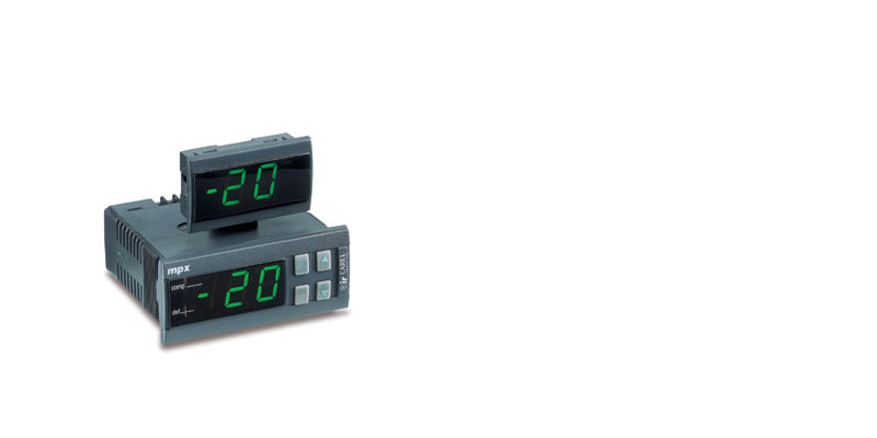
Carel IRMPX | Carel IRMPX | Carel MPX со светодиодным дисплеем специально предназначен для управления холодильными установками. Холодильные установки могут быть автономного типа или сгруппированными вместе в качестве мультиплексных шкафов |
|
|
Carel IR 33 Universale | Carel ir33 Universale |
Контроллеры серии IR33-DN33 Universale предназначены для регулирования основных физических величин (температуры, давления, влажности) в системах отопления, охлаждения и кондиционирования воздуха. Существует две основные линейки контроллеров: контроллеры первой линейки поддерживают только два датчика температуры (NTC, NTC-HT, PTC, PT1000), а контроллеры второй линейки поддерживают два датчика температуры расширенного диапазона (NTC, NTC-HT, PTC, PT100, PT1000, термопары J/K), датчики давления и влажности или датчики общего назначения (входные сигналы напряжения 0 до 1В, от 0 до 10В, от -0,5 до 1,3В, входы логометрических датчиков с сигналом 0-5В или 0-20 мА, входы сигналов тока от 4 до 20 мА) |
|
|
Carel mRack | Carel mRack | Основные функции контроллера Carel — регулировка давления всасывания компрессора, регулировка давления конденсации (нагнетание компрессора), полное управление имеющимися выходами, гибкая настройка аварийных сигналов, возможность работы в составе системы мониторинга. Управляемые устройства: компрессоры (до 4 герметичных компрессоров, без частичной нагрузки), вентиляторы конденсатора (максимум, 4), управление регулятором скорости вращения вентиляторов конденсатора сигналом PWM |
|
|
Carel MX 20 | Carel MX 20 | Carel MX20 (MPXPRO) версии FULL поддерживает следующие функции: тип контроллера (ведущий или ведомый), количество релейных выходов (3 или 5), тип подсоединяемых датчиков (датчики NTC и логометрические 0–5 В или датчики NTC/PTC/PT1000/NTC L243, активные датчики 4–20 мА, 0–10 В), наличие двух выходов ШИМ-регулирования на системной плате, наличие выхода постоянного напряжения 0–10 В на плате привода, часы реального времени (RTC) и интерфейс RS485. Есть возможность установки встроенного привода для вентилей CAREL с шаговым двигателем или электронных расширительных вентилей с ШИМ-регулированием и выхода постоянного напряжения 0–10 В на плате привода |
|
|
Carel MPXPRO | Carel MPXPRO | Контроллер Carel MPXPRO обеспечивает управление как отдельными холодильными витринами и холодильными камерами, так и централизованное управление группой витрин и камер. Контроллер может комплектоваться встроенным приводом электронного расширительного вентиля. Контроллер устанавливается на DIN-рейку и подсоединяется через съемные винтовые клеммы. Контроллер может осуществлять функции сетевого управления типа ведущий/ведомый, максимум 6 агрегатов (1 ведущий и 5 ведомых). Каждый контроллер имеет простой дисплей (только чтение) и/или графический терминал (дисплей с клавиатурой для программирования). При подключении к ведущему контроллеру терминал будет отображать параметры для всех контроллеров, включенных в локальную сеть. Контроллер может работать как ведущий или ведомый, релейных выходов (3 или 5 на ведомом контроллере), тип подсоединяемых датчиков (только датчики NTC и логометрические 0–5 В или датчики NTC/PTC/PT1000/NTC L243, логометрические 0–5 В и активные датчики 4–20 мА, 0–10 В), тип встроенного привода (для вентилей CAREL с шаговым двигателем или электронных расширительных вентилей с ШИМ-регулированием) |
|
|
Carel pCO2 | Carel pCO2 | Контроллер pCO2 – новая разработка CAREL, которая является следующей ступенью в развитии широко известной линейки контроллеров рСО. Новый контроллер специально оптимизирован для работы в сложных системах кондиционирования и охлаждения. Контроллер доступен в трех типоразмерах с различным количеством входов/выходов и разным энергопотреблением: рСО2 SMALL, рСО2 MEDIUM, рСО2 LARGE |
|
|
Carel pCO3 | Carel pCO3 | Контроллер Carel pCO3 представляет собой электронный контроллер на базе микропроцессора, аппаратно и программно совместимый с контроллерами семейства pCO2 |
|
|
Carel PJ Easy | Carel PJ Easy | Carel электронные микропроцессорные контроллеры со встроенным светодиодным дисплеем серии easy, easy compact и easy split предназначены для управления холодильными установками, охлаждаемыми прилавками и витринами |
|
|
Carel pRack PR100 | Carel pRack PR100 | Контроллер Carel pRack PR100 поддерживает 35 возможных конфигураций системы, включающей до 2 линий всасывания и до 2 линий конденсации, на отдельных устройствах или нескольких устройствах, объединенных в сеть pLAN. Конфигурация входов и выходов зависит от выбранной конфигурации системы |


IR 33
Позволяет контролировать работу вентиляторов и циклы оттайки. Имеет входы для трех датчиков, один из которых нужен для контроля температуры в камере, второй для контроля температуры испарителя, третий програмируется, чтобы управлять циклами оттайки и работой вентиляторов. Прибор обеспечен тремя реле выхода для управления компрессором, вентиляторами и оттайкой электрической или горячим газом
![]() Скачать
Скачать
PJ 32
Позволяет контролировать работу вентиляторов и циклы оттайки. Имеет входы для двух датчиков, один из которых нужен для контроля температуры в камере, другой для контроля температуры испарителя, чтобы управлять циклами оттайки и работой вентиляторов. Прибор обеспечен тремя реле выхода для управления компрессором, вентиляторами и оттайкой электрической или горячим газом
![]() Скачать
Скачать
mChiller
Регулятор mchiller специально предназначен для управления и регулировки воздухо-воздушных установок (а также установок кондиционирования воздуха с двумя ступенями нагрева, двумя ступенями охлаждения и мертвой зоной), холодильников и холодильников с тепловым насосом, оборудованным одним компрессором, установок с одним компрессором с подпрограммой управления мощностью или установок с двумя компрессорами. Регулировка вентиляторов для принудительного охлаждения конденсатора может выполняться как на базе температуры, так и давления в двухпозиционном режиме или при непрерывном изменении скорости вращения.
![]() Скачать
Скачать
РCO2swFLSTD FCOA
Данная программа предназначается для управления холодильной системой с максимальными параметрами конфигурации, включая управление 6 компрессорами с тремя ступенями управления мощности, 5 вентиляторами и 2 контроллерами. Управление основывается на показаниях двух датчиков давления, соединенных с аналоговыми входами.
![]() Скачать
Скачать
FCM
Серии контроллеров FCM управляют основными физическими величинами (температурой, давлением, влажностью) в установках кондиционирования, охлаждения и нагрева. Не смотря на то, что, будучи разработаны для общего использования, приборы серии FCM в частности эффективны в качестве контроллеров температуры/давления путем управления скоростью конденсации агрегатов.
![]() Скачать
Скачать
IRMPX
Мультиплексные устройства Мастер/Слэйв относятся к Серии MPX для охлаждения, состоящие из электронных микропроцессорных контроллеров со светодиодным дисплеем, специально предназначенные для управления холодильными установками. В этом случае холодильные установки могут быть автономного типа или сгруппированными вместе в качестве мультиплексных шкафов.
![]() Скачать
Скачать
IRUniversal
Контроллеры, входящие в серию инфракрасных приборов, специально предназначены для регулирования давления, влажности и температуры в устройствах кондиционирования воздуха, в холодильных и нагревательных установках.
![]() Скачать
Скачать
MasterCella
MasterCella является новым электронным контроллером для статических или вентилируемых холодильных установок, способным управлять всеми приводами, такими как компрессоры, вентиляторы, разморозкой, тревогами и светом.
![]() Скачать
Скачать
mRack
Основные функции: Регулировка давления всасывания компрессора; Регулировка давления конденсации (нагнетание компрессора); Полное управление имеющимися выходами; Гибкая настройка аварийных сигналов; Возможность работы в составе системы мониторинга. Управляемые устройства: Компрессоры (до 4 герметичных компрессоров, без частичной нагрузки); Вентиляторы конденсатора (максимум, 4); Управление регулятором скорости вращения вентиляторов конденсатора сигналом PWM.
![]() Скачать
Скачать
pCO2
Программируемость контроллера фирмы Carel рСО2 обеспечивает абсолютную гибкость его применения. Одни и те же аппаратные средства могут быть использованы для управления: холодильниками и тепловыми насосами; блоками, установленными на крышах; кондиционерами воздуха; малыми / средними устройствами распределения воздуха (по заказу); витринами (по заказу и по спецификации); охлаждаемыми помещениями (по заказу и по спецификации); помещениями для выдержки; холодильными блоками; универсальными переключателями замыкания контуров.
![]() Скачать
Скачать
pCO2
Список аварий выдаваемых на дисплее контроллера pCO2.
![]() Скачать
Скачать
pCO2
Параметры настройки контроллера pCO2.
![]() Скачать
Скачать
PJ 32
Новое семейство сменных устройств для систем охлаждения, предназначенных для управления холодильными установками витрин и выставок, изготовлено из электронных средств управления на микропроцессорной базе со светодиодным индикатором.
![]() Скачать
Скачать
PJ 32S
Контроллер для холодильных систем серии — S
![]() Скачать
Скачать
PJ 32-V-W-Z
Контроллер для холодильных систем серии — V,W,Z
![]() Скачать
Скачать
PJEazy
Модели S (PJEZS) — идеальное решение для управления статическим охладительным элементом (без выпарного импиллера) работающего при нормальной температуре (выше 0). Модели X и Y (PJEZX, PJEZY) — решение созданное для управления статистических элементов работающих при низкой температуре (то есть ниже 0), которые нуждаются в размораживание с помощью электрического сопротивления или с помощью введения горячего газа. Модель C (PJEZC) — самое полное решение для проветриваемых элементов на низкой температуре, оснащена тремя реле для полного управления функциями компрессора, управления импеллера и размораживания.
![]() Скачать
Скачать
PlantWatch
PlantWatch –это электронное устройство на микропроцессорной основе, предназначенное для управления сетью инструментальных средств фирмы Сarel. Данное устройство управляет и регистрирует аварийные сигналы и записи главных регулируемых величин, позволяя осуществлять передачу данных через модем к сервисному центру. Кроме этого, устройство может передавать аварийные сигналы по факсу или SMS и печатать автоматические отчеты. Основное использование устройства состоит в контроле за небольшими и средними супермаркетами.
![]() Скачать
Скачать
MX 20
Многофункциональный контроллер для холодильных систем.
![]() Скачать
Скачать
pCO3
Программное обеспечение для системы автоматического управления вентиляционной установкой. Инструкция пользователя версия 1.15. ПО предназначено для использования в контроллере pCO3, исключая версии контроллеров со встроенным терминалом PGD1 (PCO3000E** и PCO3000F**) с БИОС версии не ниже 4.35. К контроллеру может быть подключено до трех внешних терминалов PGD0****** с учетом ограничений, связанных с максимально допустимым током потребления от встроенного в контроллер источника питания для внешних терминалов: непосредственно к контроллеру может быть подключено не более одного терминала, для второго и третьего терминалов необходимо использовать внешний источник питания постоянного тока (см. документ «Система рСО. Общее руководство»).
![]() Скачать
Скачать
pRack PR100
Контроллер pRack PR100 поддерживает конфигурации системы, включающие до 2 линий всасывания (максимально 12 спиральных или поршневых компрессоров или 2 винтовых компрессора на линию) и до 2 линий конденсации (максимально 16 вентиляторов на линию). Если в системе имеются две линии всасывания, управление линиями может осуществляться одним контроллером pRack или двумя отдельными контроллерами. Управление линиями конденсации может осуществляться тем же устройством, которое управляет линией всасывания, или отдельными устройствами в соответствии с имеющимся числом входов/выходов. Для каждой линии, как всасывания, так и конденсации, контроллер pRack PR100 может управлять устройством модуляции (инвертером, компрессором Digital Scroll или компрессором с бесступенчатым регулированием). Контроллер pRack PR100 может управлять 1 линией с винтовыми компрессорами, и каждая плата может управлять 1 или 2 компрессорами.
![]() Скачать
Скачать
MicroChiller2
Панель управления позволяет быстро задать рабочие параметры холодильной машины, в любой момент визуализировать значения этих параметров и получить кратких отчет о состоянии холодильной машины. На панели имеются трехсимвольный дисплей и четыре светодиода, которые индицируют режим работы, заданные или текущие значения рабочих параметров и информацию об имеющихся аварийных ситуациях. В памяти электронной карты сохраняется информация о всех значениях рабочих параметров, заданных при последней модификации. Эта информация используется для восстановления режима работы, имевшего место перед аварийным отключением или сбоем в электропитании. При использовании панели дистанционного управления PR1 (которая входит в список дополнительного оборудования) становятся возможными дистанционные включение/отключение холодильной машины, переключение режимов (охлаждение/нагрев) и получение информации об имевших место аварийных ситуациях (аварийная ситуация индицируется свечением красного светодиода). Если используется панель дистанционного управления PRD (которая также входит в список дополнительного оборудования), становится возможным дистанционное управление всеми функциями холодильной машины – так же, как и с помощью панели управления, имеющейся на ее корпусе. Такая панель имеет четыре многофункциональных кнопки, нажимая одну или одновременно две из которых можно задать любые параметры и управлять всеми режимами работы холодильной машины.
![]() Скачать
Скачать
FLSTDmMSDE — Modular Standard Chiller HP 1/4 screw compressors with Carel
![]() Скачать
Скачать
FLSTDmMSBE — pLAN modular chiller/heat pump 1-4 screw generic and Bitzer compressors with CAREL driver EVD200
![]() Скачать
Скачать
FLSTDmMSBE — pLAN стандартная универсальная программа для управления чиллером HP 1/ 4 / винтовым компрессором Bitzer и клапаном CAREL EVD200
![]() Скачать
Скачать
FLSTDmMCDE — pLAN modular chiller/heat pump 1-8 scroll compressors with CAREL driver EVD200
![]() Скачать
Скачать
FLSTDMFC0A — Стандартная холодильная станция Рабочая программа для pCO1, pCO2, pCO3, pCOxs
![]() Скачать
Скачать
FLSTDmMSDE — Modular Standard Chiller HP 1/4 screw compressors with Carel driver Ver.2.0
![]() Скачать
Скачать
FLSTDmMSDE — Modular Standard Chiller HP 1/4 screw compressors with Carel driver Ver.2.1
![]() Скачать
Скачать
FLSTDmMSBE Ver 2.6 — pLAN modular chiller/heat pump 1-4 screw generic and Bitzer compressors with CAREL driver EVD200
![]() Скачать
Скачать
FLSTDmMSBE Ver 2.7 — pLAN modular chiller/heat pump 1-4 screw generic and Bitzer compressors with CAREL driver EVD200
![]() Скачать
Скачать
FLSTDmMCDE Ver. 3.8 — pLAN modular chiller/heat pump 1-8 scroll compressors with CAREL driver EVD200
![]() Скачать
Скачать
FLSTDMFC0A Ver.2.3 2007 — Стандартная холодильная станция Рабочая программа для pCO1, pCO2, pCO3, pCOxs
![]() Скачать
Скачать
Система pCO
![]() Скачать
Скачать
μC2SE
![]() Скачать
Скачать
Измерение сопротивления изоляции компрессора
![]() Скачать
Скачать
Вы представляете себе жизнь, если бы не было инструкций к той технике, которую Вы только что приобрели и раньше никогда не сталкивались напрямую с ее функционированием? Наверняка много вещей так бы и остались на полках прилавков, потому как люди попросту не знали, как ими пользоваться, а разбираться самостоятельно с техникой не каждый хочет. С развитием технологий скачать инструкцию по эксплуатации любой техники можно в Интернете.
Устройства компании Carel активно функционируют на техническом рынке, поэтому чем больше потребителей, тем важнее инструкция, которую можно скачать бесплатно. Все материалы предоставлены на русском языке, а сам документ дается в pdf-формате. Благодаря его наличию разобраться с функционалам любой установке будет в разы проще, особенно если с таковым вопросом Вы столкнулись впервые.
-
Contents
-
Table of Contents
-
Troubleshooting
-
Bookmarks
Quick Links
Related Manuals for Carel IRMPX00000
Summary of Contents for Carel IRMPX00000
-
Page 1
User manual… -
Page 3
We wish to save you time and money! We can assure you that a thorough reading of this manual will guarantee correct installation and safe use of the product described. -
Page 5
CONTENTS General Features ……………………………………………………………………………………………………………………………2 Main features of the multiplexed Master/Slave units……………………3 Models in the MPX series…………………………… 5 Installation ………………………………..6 Electrical connections …………………………..6 User interface — Buttons and display…………………………7 The LED display …………………………….7 Operating indications …………………………… 7 Keypad ………………………………… -
Page 7: General Features
General Features The multiplexed Master/Slave units belong to the MPX Series for refrigeration, made up of microprocessor-controlled electronic controllers with LED display, specifically designed for the management of refrigeration units. In this particular case the refrigeration units may be stand-alone type or grouped together as multiplexed cabinets. 1.
-
Page 8
Quality control includes a rigorous ‘TEST-IN-CIRCUIT’ on each single component to ensure that the controller is completely reliable. NTC probe The MPX instruments have been designed to be connected to Carel NTC probes, as these offer greater precision than other probe types. Watchdog A special device that protects the microprocessor of the controller even in the event of strong electromagnetic noise. -
Page 9: Models In The Mpx Series
The models in the MPX series have different codes according to their features. The table below lists the various codes and the corresponding options that characterise each model: OPTIONS MODEL CODE RS485 4 RELAY BUZZER IRMPX00000 • IRMPX0M000 • IRMPX0A000 • IRMPX10000 •…
-
Page 10: Installation
3. Installation Actual installation: 1) insert the instrument into the previously-created opening; 2) fasten the instrument to the panel by sliding it onto the fastening bracket. 3) insert the rear connectors of the instrument into the corresponding pre-wired connectors 4) close the panel 5) connect the power and configure the operating parameters.
-
Page 11: User Interface — Buttons And Display
4. User interface — Buttons and display Each instrument features: • 12Vac power supply; • two and a half digit display; • temperature display to the tenths; • LED indicating the output state; • 4 buttons for programming; • buzzer (according to model) PANEL-MOUNTED VERSION 4.1 The LED display The display shows temperature in the range -55 to 95ºC.
-
Page 12
— stops the audible alarm for 10 minutes(only if fitted); if pressed for over 5 seconds: — accesses the menu of the type “F” parameters (frequent); if pressed for more than 5 seconds together with button 9: — accesses the menu of the type ‘C’ parameters (configuration); — accesses the alarm log via password ( = 44) — activates the parameter download from the Master units, via password (=66) if pressed at instrument start-up:… -
Page 13: Configuration Of The Controllers
5. Configuration of the controllers. The multiplexed units are supplied ready for use. They have in fact been programmed using a default configuration so as to satisfy the more common requirements. Programming is performed by assigning all the parameters the more-frequently required value. These values are listed in the table of parameters at the end of the manual.
-
Page 14: Other Important Parameters
5.3 Other important parameters LAN configuration parameters: For the Master: • parameter “Sn” (Slave number): from 1 to 5; number of Slaves in the LAN; during boot the display shows “uM” : unit-Master • parameters for setting defrost times: “hx”, “mx”; x = 1, 2,… , 8: hours and minutes of defrost times; the tens of minutes can be set (only if RTC is present) •…
-
Page 15: List Of Parameters To Be Checked During Installation
dt: End defrost temperature This parameter allows the end defrost temperature, as measured on the evaporator, to be set. In any case, the maximum defrost time is equal to the value, in minutes, set for parameter dP. When the temperature measured by the defrost end probe is higher than the defrost end temperature set by the user, the defrost cycle will not be performed, that is, only the following dripping and, if required, post-dripping phases will take place.
-
Page 16: Programming
6. Programming The microprocessor in the MPX instruments allows the configuration of the functions of the controller according to the application requirements. To simplify this operation, we have divided the operating parameters into two main groups: • frequently used parameters (indicated as ‘F’ parameters in the tables below); •…
-
Page 17: Exiting The Programming Procedure
How to exit the procedure How to save the new set values • Press to save the new values and exit the procedure. Important: press to save the new values. In the case of power failure before has been pressed, all changes will be lost. 6.3 Exiting the programming procedure To exit the programming procedure without saving the changes, do not press any key for at least 60 seconds (TIME OUT).
-
Page 18: Programming By Remote Control
7. Programming by remote control (AVAILABLE FOR THE FOLLOWING MODELS: IRMPX0A000, IRMPX1A000, IRMPXMA000) 7.1 Remote control layout Remote-local interface buttons: PRG, SEL, KEY_UP, KEY_DOWN Numeric keypad Fig. 1 (I): Function buttons; History, PSW, ESC, ENABLE. 7.2 Introduction. The remote control for the IRMPX series has been designed to provide the user, in the palm of their hand, all the functions offered by the MPX family instruments and its local network structure: 1.
-
Page 19: Technical Specifications
7.3 Technical specifications Power supply 2 alkaline batteries, 1.5V (type UM-4 AAA, IEC R03) Case plastic Dimensions 60x160x18mm Storage -25°C÷ +70°C Operating temperature 0°C÷ 50°C Type of transmission Infrared Weight 80 g (without batteries) 7.4 Description of the keypad The buttons can be divided into the following groups, based on their functions,: •…
-
Page 20: The Psw Button And The Command Buttons
7.5 The PSW button and the command buttons. 7.5.1 The button: enter the system password from the remote control Pressing the PSW button for at least 5 seconds accesses the enter prompt for the system password (see using the local keypad and Table of parameters): •…
-
Page 21
7.6.3 ENABLING THE CONTROLLER FOR RECEIVING COMMANDS FROM THE REMOTE CONTROL ENABLE • press the button to enable the use of the remote control; • the instrument will display a two digit code (the value of parameter H3); enter the code displayed using the numeric keypad on the remote control. The code must be entered correctly, without ignoring the zeroes (e.g. -
Page 22: Re-Configuring A Control With The Default Parameters
8. Re-configuring a control with the default parameters Under exceptional conditions − high electromagnetic noise levels, for example − there may be errors when storing data. Consequently, the unit may not work correctly. When the microprocessor identifies an error in the process of storing data, one of the following groups of letters will be displayed: EA, EB, -E- The last symbol will only appear at the start-up of the instrument.
-
Page 23: The Alarm Log
9. The alarm log All the models in the MPX Series are fitted with an alarm log that records up to until 9 alarm signals. The models configured as Master and fitted with RTC also allow the display of the age of each alarm, that is, the time in hours elapsed between the moment in which the log is consulted and the time the alarm was recorded.
-
Page 24: New Local Network Functions
10. New local network functions 10.1 Network defrost for multiplexed systems The Master controls the defrost in the entire multiplexed island (cabinet controlled by the Master + cabinets controlled by the Slaves). This waits for all units to exit the actual defrost stage before sending the end defrost command to the entire network. The Slaves which have exited the actual defrost stage, await the end defrost command from the Master before passing to the dripping stage.
-
Page 25: Description Of The Configuration Parameters
11. DESCRIPTION OF THE CONFIGURATION PARAMETERS 11.1 Configuration parameters As already mentioned, (see chapter on how to modify the operating parameters), there are two types of parameter: • parameters used frequently (indicated by ‘F’ in the following tables) • configuration parameters (type C), which are protected by a password to prevent unwanted modification. 11.2 Parameter categories Besides being divided into TYPES, the parameters are grouped into logical categories labelled by letters indicating their function.
-
Page 26: Parameters For The Management Of The Temperature Probes
Short descriptive note about probes with NTC- and PTC-type thermistors: Units in the MPX series are designed to work with Carel NTC temperature probes, or probes using thermistors with a negative characteristic (NTC stands for Negative Temperature Coefficient). This type of thermistor modifies an electrical parameter (its own resistance) in inverse proportion to any change in temperature;…
-
Page 27
/2: Stability of measurement This parameter is used to control the stability with which the temperature is measured. Low values assigned to this parameter produce a prompt response by the probe to variations in temperature; however, the display becomes correspondingly sensitive to changes. High values slow down the response, causing less fluctuation and a more stable reading. -
Page 28: R = Parameters For Temperature Regulation
/9: defrost with probe 3 This parameter allows a defrost to be carried out using probes S2 and S3 together, if set to 1. In this case the temperature defrost ends when the temperature measured by both probes is greater than or equal to that set as the end defrost temperature (See parameter “dt”). Probe 3 can therefore be used as a defrost probe on a second evaporator.
-
Page 29
rd: Regulation delta Sets the value of the differential, or hysteresis, used in regulating the temperature. A narrow differential, i.e. one with a low number, ensures a temperature that differs little from the set-point (or optimal operating temperature), but one that requires the frequent switching on and off of the main operating components (normally the compressor). -
Page 30: C = Parameters For Compressor Management
To inhibit monitoring and/or reset the values recorded, set “r5” to 0. After 199 hours the measuring of the max. and min. temperatures is halted, having reached the maximum monitoring time allowed by the instrument. Modify “r5” to perform monitoring again (first set to 0 using the arrows and the SEL button and then to the required value between 1 and 5, again using the arrows and SEL.
-
Page 31
c0: Delay in switching on the compressor and fans (if controlled) after switching on the instrument From when power is supplied to the controller, the start-up of the compressor is delayed by a time (in minutes) equal to the value assigned a this parameter. -
Page 32
c4: Duty setting or safety relay If the “regulation error” alarm occurs (that is, probes S1 and/or S3 are short-circuited or disconnected) this parameter ensures the operation of the compressor until of the elimination of the fault. As the compressor is unable to function based on the temperature (because of the faulty probe), it is activated cyclically with an operating time («ON time») in minutes equivalent to the value assigned to c4 and a fixed OFF time of 15 minutes. -
Page 33: D = Parameters For Defrost Management
11.7 d = Parameters for defrost management DEFROST PARAMETERS Type Max. Def. To LAN • Defrost types 0 = electrical: ends by temperature and/or for timeout 1 = hot gas: ends by temperature and/or for timeout 2 = electrical: ends for timeout 3= hot gas: ends for timeout •…
-
Page 34
dt: End defrost temperature set-point This parameter allows the setting of the temperature of the evaporator at which the defrost is ended (the temperature of the evaporator is measured by the defrost probe: probe 2). If at the start of a defrost (d0 = 0) the temperature measured by the defrost probe is greater than the set end defrost temperature, the unit goes directly to the dripping phase (See further on, network defrost). -
Page 35
The defrost cycle thus becomes the condensate discharge cycle, which needs to be started at short intervals (minutes) and for very brief periods (seconds). Contact your Carel agent for further information. — Parameter can be transferred via LAN from the Master to its connected Slaves. -
Page 36: A = Parameters For Alarm Control
11.8 A = parameters for alarm control ALARM PARAMETERS Type Max. Def. °C/°F • Fan and alarm differential °C/°F • High temperature alarm: indicates the maximum variation from +199 the set-point. AH = 0 excludes the high temperature alarm °C/°F •…
-
Page 37: Digital Inputs And Description Of The Interface Commands For The Supervisor
AL: Minimum temperature alarm This parameter allows the low temperature alarm to be selected. The value of AL does not indicate the temperature at which the alarm will sound, but rather the maximum deviation from the set-point (i.e. the requested operating temperature) that is permitted. The low temperature alarm is given as follows: Low temperature alarm <…
-
Page 38
When the alarm ceases the unit resumes normal temperature control operation. WARNING: If A8 = 1 the alarm can be activated by a specific command from the supervisory system (if the latter exploits the functions supplied by the MPXs) or, on Slave units where A8 = 1, by the opening of the digital input DIN2 on the Master. Important note: it should be remembered that to guarantee the safety of the unit in the case of serious alarms, the unit itself must always be fitted with all the electro-mechanical safety devices needed to ensure correct operation. -
Page 39
A4/A5/A8 = 5: Door Switch Setting A4/A5/A8= 5 controls the switch on the store-room door. When the switch is opened the compressor and the fans are switched off and the lights are switched on (if at least one of the two fan or AUX relays is configured as an auxiliary and is used as a light relay). When the door is closed (as well as the Multifunction contact), the unit resumes the previous operation, delaying any temperature alarm by a number of hours equivalent to the value of d8. -
Page 40
A9: Enable the propagation via the LAN of the Master’s second digital input This parameter is accessible only for instruments configured as Master. It allows “parallel connection” to the virtual digital input on the connected Slave units of the Master’s second (physical) digital input DIN2. In this way, the second digital input of the Master may be propagated or not to the Slaves. -
Page 41: F = Parameters For Controlling The Evaporator Fans
11.10 F = parameters for controlling the evaporator fans FAN PARAMETERS Type Max. Def. To LAN • Fan management: flag 0 = fan always ON (except in special cases: see parameters F2, F3, Fd) 1 = fans thermostat-controlled in accordance with the absolute set-point F1 °C/°F •…
-
Page 42: H = Other Settings
11.11 H = other settings OTHER PRE-SETTINGS Type Max. Def. To LAN Serial address (only for the network Master) Relay 4 selection: flag 0 = auxiliary output 1 = alarm relay, normally open (closed in alarm) 2 = alarm relay, normally closed (open in alarm) 3 = auxiliary relay: Master serves the Slaves;…
-
Page 43
• In = 0: unit configured as Slave — Available on all models — The default for this parameter depends on the model of the instrument; see the second row of the following table for the default values of the various models: IRMPX00000 IRMPX0M000 IRMPX0A000 IRMPX10000… -
Page 44: Operating States Of The Units
12. Operating states of the units As indicated above, the display LEDs can be in three states: • off, when the function indicated or the actuator is not operative; • on, when the function indicated or the actuator is operative; •…
-
Page 45
13. Alarms 13.1 Defective or incorrect operation The units in the MPX range are able to signal most incorrect operations automatically. When a malfunction occurs, the microprocessor initiates the following actions: • the malfunction is signalled on the display by an appropriate alarm code. More specifically, the display shows the alarm code and the temperature read by the probe, alternating in sequence. -
Page 46: Alarms
HI FLASHING High temperature alarm. The probe has measured a temperature further above the set value than the value set for parameter AH. • Check parameters AH, Ad and A0. • The alarm will cease as soon as the temperature returns within the set limits (see parameter AH). EA, EB DISPLAYED DURING OPERATION OR WHEN SWITCHING-ON Data acquisition error.
-
Page 47: Troubleshooting
14. Troubleshooting PROBLEM CAUSE CHECK compressor does not start : compressor delay in progress parameters c0, c1 and c2 • power on • compressor LED flashing temperature is outside set limits but no alarm alarm delay in progress check Ad signalled and the buzzer, if fitted, does not sound the AL or Ad alarm signalled (Multi-function…
-
Page 48: Technical Specifications
15. Technical specifications 15.1 Technical characteristics: Probe type: NTC Carel Operating field: -55°c — +95°c ± 0.5°C Precision : Storage: -10°C/ 70°c Operating conditions: 0°C/+50°c Power supply: 12Vac Power consumption: 150mA Front panel index of protection: IP65 with panel mounted and gasket inserted…
-
Page 49: Temperature/Resistance Ratios For Ntc Thermistors
Rmax is the maximum value. For the sake of simplicity, the values corresponding to only a limited number of temperatures are given. Intermediate values can be determined by interpolation. Temperature/Resistance ratios for the Carel NTC temperature probe Temperature Rmin Rstd Rmax -40 ºC…
-
Page 50: View Of The Instrument
15.3 View of the instrument Dimensions of the MPX in mm: 25/06/01 Cod. +030220191 rel. 2.0 dated…
-
Page 51: Wiring Diagrams
16. WIRING DIAGRAMS Master/Slave connection wiring diagram: Transformer Transformer Transformer (*) Insulating Transformer transformer Example of wiring for serial connection of the instruments: Main = mains power supply TRF = transformer INS TRF = insulating transformer = earth SER = multiple connection to the controller system 16.1 MPX contact rear view: Label of connections for the IRMPX10000 model (slave with 4 relays): Label of connections for the IRMPXM0000 model (Master with 485):…
-
Page 52: Summary Of Parameters
17. Summary of parameters PARAMETER Type Min. Max. Def. To LAN 2 PASSWORD PARAMETERS LOG PASSWORD DOWNLOAD PASSWORD PROBE PARAMETERS Type Min. Max. Def. To LAN Temperature set-point °C/°F -10.0 • °C/°F Regulation probe calibration Measurement stability Probe reading rate •…
-
Page 53
COMPRESSOR PARAMETERS Type Min. Max. Def. To LAN • Compressor start delay when the instrument is turned ON min. • Minimum time between two successive compressor starts min. • Minimum compressor off time min. • Minimum compressor on time min. •… -
Page 54
FAN PARAMETERS Type Min. Max. Def. To LAN • Fan management: flag 0 = fan always ON (except in special cases: see parameters F2, F3, 1 = fans thermostat-controlled in accordance with the absolute set- point F1 °C/°F • Fan start absolute set-point Active if F0 = 1 •… -
Page 55
Note: ___________________________________________________________________________________ ________________________________________________________________________________________ ________________________________________________________________________________________ ________________________________________________________________________________________ ________________________________________________________________________________________ ________________________________________________________________________________________ ________________________________________________________________________________________ ________________________________________________________________________________________ ________________________________________________________________________________________ ________________________________________________________________________________________ ________________________________________________________________________________________ ________________________________________________________________________________________ ________________________________________________________________________________________ ________________________________________________________________________________________ ________________________________________________________________________________________ ________________________________________________________________________________________ ________________________________________________________________________________________ ________________________________________________________________________________________ ________________________________________________________________________________________ ________________________________________________________________________________________ ________________________________________________________________________________________ ________________________________________________________________________________________ ________________________________________________________________________________________ ________________________________________________________________________________________ ________________________________________________________________________________________ ________________________________________________________________________________________… -
Page 56
Note: ___________________________________________________________________________________ ________________________________________________________________________________________ ________________________________________________________________________________________ ________________________________________________________________________________________ ________________________________________________________________________________________ ________________________________________________________________________________________ ________________________________________________________________________________________ ________________________________________________________________________________________ ________________________________________________________________________________________ ________________________________________________________________________________________ ________________________________________________________________________________________ ________________________________________________________________________________________ ________________________________________________________________________________________ ________________________________________________________________________________________ ________________________________________________________________________________________ ________________________________________________________________________________________ ________________________________________________________________________________________ ________________________________________________________________________________________ ________________________________________________________________________________________ ________________________________________________________________________________________ ________________________________________________________________________________________ ________________________________________________________________________________________ ________________________________________________________________________________________ ________________________________________________________________________________________ ________________________________________________________________________________________ ________________________________________________________________________________________… -
Page 57
Note: ___________________________________________________________________________________ ________________________________________________________________________________________ ________________________________________________________________________________________ ________________________________________________________________________________________ ________________________________________________________________________________________ ________________________________________________________________________________________ ________________________________________________________________________________________ ________________________________________________________________________________________ ________________________________________________________________________________________ ________________________________________________________________________________________ ________________________________________________________________________________________ ________________________________________________________________________________________ ________________________________________________________________________________________ ________________________________________________________________________________________ ________________________________________________________________________________________ ________________________________________________________________________________________ ________________________________________________________________________________________ ________________________________________________________________________________________ ________________________________________________________________________________________ ________________________________________________________________________________________ ________________________________________________________________________________________ ________________________________________________________________________________________ ________________________________________________________________________________________ ________________________________________________________________________________________ ________________________________________________________________________________________ ________________________________________________________________________________________… -
Page 59
Agency: CAREL srl Via dell’Industria, 11 — 35020 Brugine — Padova (Italy) Tel. (+39) 049.9716611 Fax (+39) 049.9716600 http://www.carel.com — e-mail: carel@carel.com…
инструкцияCarel MPXPRO

Интегрированные системы управления и энергосбережение
NO POWER
& SIGNAL
CABLES
TOGETHER
READ CAREFULLY IN THE TEXT!
MPXPRO
Электронный контроллер
Руководство пользователя
Посмотреть инструкция для Carel MPXPRO бесплатно. Руководство относится к категории Без категории, 4 человек(а) дали ему среднюю оценку 8.5. Руководство доступно на следующих языках: русский. У вас есть вопрос о Carel MPXPRO или вам нужна помощь? Задайте свой вопрос здесь
Нужна помощь?
У вас есть вопрос о Carel а ответа нет в руководстве? Задайте свой вопрос здесь Дай исчерпывающее описание проблемы и четко задайте свой вопрос. Чем детальнее описание проблемы или вопроса, тем легче будет другим пользователям Carel предоставить вам исчерпывающий ответ.
Количество вопросов: 0

![]()
Главная
Не можете найти ответ на свой вопрос в руководстве? Вы можете найти ответ на свой вопрос ниже, в разделе часто задаваемых вопросов о Carel MPXPRO.
Инструкция Carel MPXPRO доступно в русский?
Не нашли свой вопрос? Задайте свой вопрос здесь
Описание
Товар категории Б/У, проверен и находится полностью в рабочем состоянии.
Файлы для скачивания
Доставка и оплата
Доставка осуществляется следующими способами:
- Доставка курьером
- Доставка транспортной компанией
- Самовывоз со склада
Подробнее: Способы доставки по России
Оплатить можно:
- Выписать счёт на оплату
- Оплатить наличными при получении товара на складе
Подробнее: Способы оплаты
Технические характеристики
| БУ | Y |
| Артикул: | IRMPXMB000 |
| Производитель: | Carel |
| Степень защиты, IP: | 65 |
| Размер посадочного места, мм: | 71х29 |
| Способ монтажа: | на панель |
| Тип датчика: | NTC/цифр.вх. |
| Тип напряжения: | Перем. |
| Количество выходов: | 4 |
| Тип выхода: | Реле |
| Размер габаритный, мм: | 75х34х75 |
IRMPX*
Общие характеристики
Контроллер CAREL серии mpx типа MASTER предназначен для централизованного управления холодильными витринами в супермаркетах и морозильными камерами. Можно объединить в сеть mpxLAN в сумме до 6 контроллеров для организации управления по принципу ведущий/ведомый.
Некоторые функции регулирования и некоторые параметры (через функцию копированию) можно использовать централизованного во всех контроллерах, объединенных сетью mpxLAN. К системе диспетчерского управления подключается ведущий контроллер.
Плата часов, установленная в ведущем контроллере, предназначена для управления циклами оттайки всех холодильных витрин, включенных в сеть mpxLAN (до 8 расписаний оттайки). Кроме того, кнопки управления контроллера соответствуют требованиям стандартов ХАССП.
Электрические разъемы быстро и легко подсоединяются и отсоединяются. Модель, оснащенная 4 релейными выходами, может управлять компрессором (или электронным вентилем), оттайкой оборудования и вентиляторами испарителя, а дополнительное МНОГОФУНКЦИОНАЛЬНОЕ реле можно использовать для управления включением/выключением освещения или аварийной сигнализации.
При необходимости в параметрах ведущего контроллера можно настроить, чтобы он работал как ведомый. Контроллер серии mpx типа SLAVE подключается к ведущему контроллеру в сети mpxLAN по2-проводной схеме и всего в сети может насчитываться до 6 контроллеров (1 ведущий + 5 ведомых). Каждый контроллер mpx управляет своей холодильной установкой совершенно независимо, но согласованно с другими контроллерами. Наличие в сети ведущего контроллера позволяет осуществлять оттайку всех витрин синхронно.
Документация
Commercial
-
Брошюра
Код Описание Язык Дата * Выпуск Код
+30C239431Описание
陈列柜和冷库的应用 解决方案Язык
CHIДата
01/10/2006
Выпуск
1.0
Позволяет контролировать работу вентиляторов и циклы оттайки. Имеет входы для трех датчиков, один из которых нужен для контроля температуры в камере, второй для контроля температуры испарителя, третий програмируется, чтобы управлять циклами оттайки и работой вентиляторов. Прибор обеспечен тремя реле выхода для управления компрессором, вентиляторами и оттайкой электрической или горячим газом
![]() Скачать
Скачать
Позволяет контролировать работу вентиляторов и циклы оттайки. Имеет входы для двух датчиков, один из которых нужен для контроля температуры в камере, другой для контроля температуры испарителя, чтобы управлять циклами оттайки и работой вентиляторов. Прибор обеспечен тремя реле выхода для управления компрессором, вентиляторами и оттайкой электрической или горячим газом
![]() Скачать
Скачать
Регулятор mchiller специально предназначен для управления и регулировки воздухо-воздушных установок (а также установок кондиционирования воздуха с двумя ступенями нагрева, двумя ступенями охлаждения и мертвой зоной), холодильников и холодильников с тепловым насосом, оборудованным одним компрессором, установок с одним компрессором с подпрограммой управления мощностью или установок с двумя компрессорами. Регулировка вентиляторов для принудительного охлаждения конденсатора может выполняться как на базе температуры, так и давления в двухпозиционном режиме или при непрерывном изменении скорости вращения.
![]() Скачать
Скачать
Данная программа предназначается для управления холодильной системой с максимальными параметрами конфигурации, включая управление 6 компрессорами с тремя ступенями управления мощности, 5 вентиляторами и 2 контроллерами. Управление основывается на показаниях двух датчиков давления, соединенных с аналоговыми входами.
![]() Скачать
Скачать
Серии контроллеров FCM управляют основными физическими величинами (температурой, давлением, влажностью) в установках кондиционирования, охлаждения и нагрева. Не смотря на то, что, будучи разработаны для общего использования, приборы серии FCM в частности эффективны в качестве контроллеров температуры/давления путем управления скоростью конденсации агрегатов.
![]() Скачать
Скачать
Мультиплексные устройства Мастер/Слэйв относятся к Серии MPX для охлаждения, состоящие из электронных микропроцессорных контроллеров со светодиодным дисплеем, специально предназначенные для управления холодильными установками. В этом случае холодильные установки могут быть автономного типа или сгруппированными вместе в качестве мультиплексных шкафов.
![]() Скачать
Скачать
Контроллеры, входящие в серию инфракрасных приборов, специально предназначены для регулирования давления, влажности и температуры в устройствах кондиционирования воздуха, в холодильных и нагревательных установках.
![]() Скачать
Скачать
MasterCella является новым электронным контроллером для статических или вентилируемых холодильных установок, способным управлять всеми приводами, такими как компрессоры, вентиляторы, разморозкой, тревогами и светом.
![]() Скачать
Скачать
Основные функции: Регулировка давления всасывания компрессора; Регулировка давления конденсации (нагнетание компрессора); Полное управление имеющимися выходами; Гибкая настройка аварийных сигналов; Возможность работы в составе системы мониторинга. Управляемые устройства: Компрессоры (до 4 герметичных компрессоров, без частичной нагрузки); Вентиляторы конденсатора (максимум, 4); Управление регулятором скорости вращения вентиляторов конденсатора сигналом PWM.
![]() Скачать
Скачать
Программируемость контроллера фирмы Carel рСО2 обеспечивает абсолютную гибкость его применения. Одни и те же аппаратные средства могут быть использованы для управления: холодильниками и тепловыми насосами; блоками, установленными на крышах; кондиционерами воздуха; малыми / средними устройствами распределения воздуха (по заказу); витринами (по заказу и по спецификации); охлаждаемыми помещениями (по заказу и по спецификации); помещениями для выдержки; холодильными блоками; универсальными переключателями замыкания контуров.
![]() Скачать
Скачать
Список аварий выдаваемых на дисплее контроллера pCO2.
![]() Скачать
Скачать
Параметры настройки контроллера pCO2.
![]() Скачать
Скачать
Новое семейство сменных устройств для систем охлаждения, предназначенных для управления холодильными установками витрин и выставок, изготовлено из электронных средств управления на микропроцессорной базе со светодиодным индикатором.
![]() Скачать
Скачать
Контроллер для холодильных систем серии — S
![]() Скачать
Скачать
Контроллер для холодильных систем серии — V,W,Z
![]() Скачать
Скачать
Модели S (PJEZS) — идеальное решение для управления статическим охладительным элементом (без выпарного импиллера) работающего при нормальной температуре (выше 0). Модели X и Y (PJEZX, PJEZY) — решение созданное для управления статистических элементов работающих при низкой температуре (то есть ниже 0), которые нуждаются в размораживание с помощью электрического сопротивления или с помощью введения горячего газа. Модель C (PJEZC) — самое полное решение для проветриваемых элементов на низкой температуре, оснащена тремя реле для полного управления функциями компрессора, управления импеллера и размораживания.
![]() Скачать
Скачать
PlantWatch –это электронное устройство на микропроцессорной основе, предназначенное для управления сетью инструментальных средств фирмы Сarel. Данное устройство управляет и регистрирует аварийные сигналы и записи главных регулируемых величин, позволяя осуществлять передачу данных через модем к сервисному центру. Кроме этого, устройство может передавать аварийные сигналы по факсу или SMS и печатать автоматические отчеты. Основное использование устройства состоит в контроле за небольшими и средними супермаркетами.
![]() Скачать
Скачать
Многофункциональный контроллер для холодильных систем.
![]() Скачать
Скачать
Программное обеспечение для системы автоматического управления вентиляционной установкой. Инструкция пользователя версия 1.15. ПО предназначено для использования в контроллере pCO3, исключая версии контроллеров со встроенным терминалом PGD1 (PCO3000E** и PCO3000F**) с БИОС версии не ниже 4.35. К контроллеру может быть подключено до трех внешних терминалов PGD0****** с учетом ограничений, связанных с максимально допустимым током потребления от встроенного в контроллер источника питания для внешних терминалов: непосредственно к контроллеру может быть подключено не более одного терминала, для второго и третьего терминалов необходимо использовать внешний источник питания постоянного тока (см. документ «Система рСО. Общее руководство»).
![]() Скачать
Скачать
Контроллер pRack PR100 поддерживает конфигурации системы, включающие до 2 линий всасывания (максимально 12 спиральных или поршневых компрессоров или 2 винтовых компрессора на линию) и до 2 линий конденсации (максимально 16 вентиляторов на линию). Если в системе имеются две линии всасывания, управление линиями может осуществляться одним контроллером pRack или двумя отдельными контроллерами. Управление линиями конденсации может осуществляться тем же устройством, которое управляет линией всасывания, или отдельными устройствами в соответствии с имеющимся числом входов/выходов. Для каждой линии, как всасывания, так и конденсации, контроллер pRack PR100 может управлять устройством модуляции (инвертером, компрессором Digital Scroll или компрессором с бесступенчатым регулированием). Контроллер pRack PR100 может управлять 1 линией с винтовыми компрессорами, и каждая плата может управлять 1 или 2 компрессорами.
![]() Скачать
Скачать
Панель управления позволяет быстро задать рабочие параметры холодильной машины, в любой момент визуализировать значения этих параметров и получить кратких отчет о состоянии холодильной машины. На панели имеются трехсимвольный дисплей и четыре светодиода, которые индицируют режим работы, заданные или текущие значения рабочих параметров и информацию об имеющихся аварийных ситуациях. В памяти электронной карты сохраняется информация о всех значениях рабочих параметров, заданных при последней модификации. Эта информация используется для восстановления режима работы, имевшего место перед аварийным отключением или сбоем в электропитании. При использовании панели дистанционного управления PR1 (которая входит в список дополнительного оборудования) становятся возможными дистанционные включение/отключение холодильной машины, переключение режимов (охлаждение/нагрев) и получение информации об имевших место аварийных ситуациях (аварийная ситуация индицируется свечением красного светодиода). Если используется панель дистанционного управления PRD (которая также входит в список дополнительного оборудования), становится возможным дистанционное управление всеми функциями холодильной машины – так же, как и с помощью панели управления, имеющейся на ее корпусе. Такая панель имеет четыре многофункциональных кнопки, нажимая одну или одновременно две из которых можно задать любые параметры и управлять всеми режимами работы холодильной машины.
![]() Скачать
Скачать
![]() Скачать
Скачать
![]() Скачать
Скачать
![]() Скачать
Скачать
![]() Скачать
Скачать
![]() Скачать
Скачать
![]() Скачать
Скачать
![]() Скачать
Скачать
![]() Скачать
Скачать
![]() Скачать
Скачать
![]() Скачать
Скачать
![]() Скачать
Скачать
![]() Скачать
Скачать
![]() Скачать
Скачать
![]() Скачать
Скачать
Вы представляете себе жизнь, если бы не было инструкций к той технике, которую Вы только что приобрели и раньше никогда не сталкивались напрямую с ее функционированием? Наверняка много вещей так бы и остались на полках прилавков, потому как люди попросту не знали, как ими пользоваться, а разбираться самостоятельно с техникой не каждый хочет. С развитием технологий скачать инструкцию по эксплуатации любой техники можно в Интернете.
Устройства компании Carel активно функционируют на техническом рынке, поэтому чем больше потребителей, тем важнее инструкция, которую можно скачать бесплатно. Все материалы предоставлены на русском языке, а сам документ дается в pdf-формате. Благодаря его наличию разобраться с функционалам любой установке будет в разы проще, особенно если с таковым вопросом Вы столкнулись впервые.
Описание
Товар категории Б/У, проверен и находится полностью в рабочем состоянии.
Файлы для скачивания
Доставка и оплата
Доставка осуществляется следующими способами:
- Доставка курьером
- Доставка транспортной компанией
- Самовывоз со склада
Подробнее: Способы доставки по России
Оплатить можно:
- Выписать счёт на оплату
- Оплатить наличными при получении товара на складе
Подробнее: Способы оплаты
Технические характеристики
| БУ | Y |
| Артикул: | IRMPXMB000 |
| Производитель: | Carel |
| Степень защиты, IP: | 65 |
| Размер посадочного места, мм: | 71х29 |
| Способ монтажа: | на панель |
| Тип датчика: | NTC/цифр.вх. |
| Тип напряжения: | Перем. |
| Количество выходов: | 4 |
| Тип выхода: | Реле |
| Размер габаритный, мм: | 75х34х75 |