Raspberry Pi HDMI Display

5 inch HDMI Display-B
Download Tutorials

7 inch HDMI Display-C
Download Tutorials

7inch HDMI Display-H
Download Tutorials
10.1inch HDMI Display-H
Download Tutorials
Raspberry Pi GPIO Display

2.4 inch RPi Display
Download Tutorials

2.8 inch RPi Display
Download Tutorials

3.2 inch RPi Display
Download Tutorials

3.5 inch RPi Display
Download Tutorials
Starter Learning Kit

LA036 Super Starter Kit for Arduino UNO(CH340)
Download Tutorials

LA037 Basic Starter Kit for Arduino UNO(CH340)
Download Tutorials

LA009 Ultimate Starter Kit for UNO R3
Download Tutorials

LA008 Ultimate Starter Kit for Mega 2560
Download Tutorials

LA010 Super Learning Kit for UNO R3
Download Tutorials

LA026 Super Learning Kit for UNO R3(CH340)
Download Tutorials

LA023 Super Starter Kit for Raspberry Pi
Download Tutorials

LA002 Basic Starter Kit UNO R3 Project
Download Tutorials

LA007 Power Supply Learning Kit UNO R3 Project
Download Tutorials

LA012 Basic Learning Kit
Download Tutorials

LA019 37 Sensor Kit
Download Tutorials

H001 Hosyond Super Starter Kit
Download Tutorials

LA043 ESP32 Basic Starter Kit
Download Tutorials

LA045 Raspberry Pi Pico Starter Kit
Download Tutorials
Arduino Robot Kit

LA015 Multi-Functional Smart Car Kit
Download Tutorials

LA016 4WD Smart Robot Car Kit V1
Download Tutorials

LA018 2WD Smart Robot Car Kit V1
Download Tutorials

LA038 4WD Smart Robot Car Kit V2
Download Tutorials

LA039 2WD Smart Robot Car Kit V2
Download Tutorials

LA040 4WD Robot Arm Smart Car
Download Tutorials

LA033 Smart Robot Tank Kit
Download Tutorials

LA035 Smart Home Kit
Download Tutorials

LA027 4DOF Smart Robot Arm Kit
Download Tutorials

LA028 4DOF Panda Robot Kit
Download Tutorials

LA013 iBot Programming Education Robot Car
Download Tutorials

LA029 Micro:bit Smart Robot Car
Download Tutorials

LA017 Smart Turtle Robot Car Kit
Download Tutorials

H003 2WD Smart Robot Car Kit
Download Tutorials

H004 4WD Smart Robot Car Kit
Download Tutorials

LA041 ESP32 Cam Robot Car
Download Tutorials

LA042 Solar Tracking Kit
Download Tutorials

LA044 WiFi Camera Smart Robot Car
Download Tutorials

Arduino Mini Radar Kit
Download Tutorials
Hide thumbs
Also See for 4DOF:
- Manual (249 pages)
-
Contents
-
Table of Contents
-
Bookmarks
Quick Links
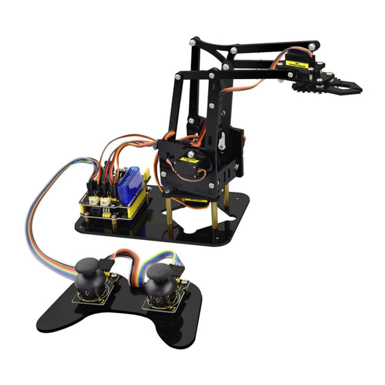
keyestudio 4DOF Robot Mechanical Arm Kit for Arduino DIY
Related Manuals for Keyestudio 4DOF
Summary of Contents for Keyestudio 4DOF
-
Page 1
4DOF Robot Mechanical Arm Kit for Arduino DIY… -
Page 2: Table Of Contents
CONTENT GUIDE 1. Kit Overview…………………………………………1 2. Kit Features…………………………………………1 3. Part List…………………………………………..3 4. Assembly Guide……………………………………….. 11 Step1: Begin with the Baseplate Assembly……………………………….11 Step2: Assemble Arm Middle Parts………………………………….28 Step3: Assemble the Claw Servo Plate………………………………..65 Step4: Final Assembly……………………………………..79 Step5: Assemble the Joystick Control Plate………………………………87 5.
-
Page 3
Project 4: Bluetooth Controlled Robot Arm………………………………199 1) Principle of Bluetooth Control………………………………..199 2) Bluetooth Control Key Test………………………………….. 201 3) Bluetooth Controlling Arm………………………………….206 Project 5: PS2 Controlled Robot Arm (Extension)…………………………….214 1) PS2 Joypad Key Test……………………………………214 2) PS2 Joypad Control……………………………………223 3) PS2 Controlling Posture Memory………………………………… 235 4) PS2 Controlling Posture Memory And Loop……………………………. -
Page 4: Kit Overview
DIY your own controllable mechanical arm using ARDUINO microcontroller. It uses UNO R3 and 2 JoyStick modules to control the angle degree of 4 servos. When DIY this 4DOF robot arm kit, you could get everything needed for arm installation and debugging. There are 3 controlling methods are as follows: 1) Controlling through Wired JoyStick (included in the kit);…
-
Page 5
Detailed debugging methods, starting Arduino from entry. Three controlling methods: Wired JoyStick Control; Phone Bluetooth Control; Wireless PS2 JoyStick Control. The parameters of keyestudio TB6612FNG motor/servo drive expansion board are as follows: VIN voltage: VIN = DC 7-15V VIN current: 5A … -
Page 6: Part List
3. Part List You can see a pretty beautiful packaging box for the arm kit, and inside the packaging you will find all the parts and screws listed below. Picture Item Quantity Keyestudio UNO R3 Main Board keyestudio TB6612FNG motor/servo drive shield…
-
Page 7
MeArm T=3MM Black Acrylic panels MeArm T=3MM Black Acrylic handle MeArm Black ABS Cylindrical holder Diameter 42mm… -
Page 8
Black 180° Servo Keyestudio Bluetooth Module-(HC-06) Keyestudio Joystick Module 3D PS2 Joystick cap… -
Page 9
Yellow-black handle 3*40MM Phillips Screwdriver Galvanized M2+M3 2mm thin double-headed small wrench M3*6MM round-head cross screw M3*10MM round-head cross screw M3*16MM round-head screw… -
Page 10
M3*14MM flat-head screw M3*12MM round-head cross screw M3*24+6MM copper pillar M3*6mm+6mm copper pillar M3 Stainless steel Hex Nut… -
Page 11
M3 hexagon Lock Nut M1.2x5MM Phillips tapping screw M2x5MM Phillips tapping screw M3 304 Stainless steel flat washer 3*7*0.5MM… -
Page 12
M2x8MM Phillips tapping screw M3*16MM flat-head screw Male to female 10CM jumper wire female to female 50CM jumper wire… -
Page 13
Black 3*100MM cable ties 18650 dual-cell battery case with plug lead 15CM… -
Page 14: Assembly Guide
4. Assembly Guide Follow the assembly steps below to build your own robot arm, believe you will be full of delight to experience the robot arm DIY. If still confused, you can refer to the assembly video. Step1: Begin with the Baseplate Assembly (1) Firstly, you should prepare the components as follows: …
-
Page 15
Then, screw the copper pillars with M3 hex nuts on the black Acrylic baseplate. Rear Front… -
Page 16
(2) Then install the control board, and prepare the components as follows: M3*6MM round-head screw *3 Keyestudio UNO R3 board *1 keyestudio TB6612FNG motor shield *1… -
Page 17
Firstly, screw the UNO R3 board on the pillar using three M3*6MM round-head screws. -
Page 18
Then stack the motor drive shield onto the UNO R3 board. -
Page 19
(3) Completed the above assembly, let’s mount the Pivot Servo Plate onto the base. M3*12MM round-head screw *2 M3 hex lock Nut *2 Black 180° servo *1 Acrylic plate * 4… -
Page 20
Note: before install the servo, should set the servo angle to 80 degrees. To set the servo angle, first connect the servo to A0 of motor shield, upload the code below to UNO R3 board, powered on, press the reset button, servo will rotate to 80°. -
Page 21
Code for 80° Servo: ************************************************* int servopin=A0;//Define digital interface A0 to connect servo steering gear signal line int myangle; //Define angle variables int pulsewidth; //Define pulse width variables void setup() pinMode(servopin,OUTPUT); //Set steering gear interface as Output void servopulse(int servopin,int myangle) //Define Function pulsewidth=(myangle*11)+500;… -
Page 22
//80 Degree Code: servopulse(servopin,80); //180 Degree Code: servopulse(servopin,180); ************************************************* Notice: Set well the servo angle and complete the below servo base plate assembly, power off the servo to avoid the angle error and make sure the servo can rotate freely. Don’t over-tighen the screws. -
Page 23
Adjusted well the servo motor, start to install the Servo Base Plate. Follow the marks. -
Page 24
Firstly mount the acrylic plate to the servo motor. ②… -
Page 25
Then mount the two acrylic plates to the servo using two M3*12MM round-head screws. ④… -
Page 26
After that, screw the acrylic plate to the servo using two M3 hex lock Nuts ⑤ ⑥… -
Page 27
You should get the detailed view shown below (pay close attention to red mark). Front Rear… -
Page 28
You should get the complete Servo Base Part. -
Page 29
(4) Now you should install the Servo Base part to the Base Plate: M3*6MM round-head hex screw *4… -
Page 30
Install the Servo plate to the Base Plate using four M3*6MM round-head hex screws. -
Page 31: Step2: Assemble Arm Middle Parts
Step2: Assemble Arm Middle Parts (1) In the following section, assemble the Left Arm Servo Plate. Prepare: M3*12MM round-head screw *2 M3 hex lock nut *2 M2x5MM Phillips tapping screw *1 M2x8MM Phillips tapping screw *1 …
-
Page 32
Note: before install the servo plate, should set the servo angle to 180 degrees. The method is the same as 80° servo settings mentioned above. You just need to change the servopulse(servopin,80) into servopulse(servopin,180) in the code. -
Page 33
Now assemble the Left Arm Servo Plate as below. (pay close attention to servo direction, rocker connected to servo and marked position) -
Page 34
Firstly mount the acrylic plate to the Left servo motor. ②… -
Page 35
Second, mount the two acrylic plates to the servo using two M3*12MM round-head screws . You ④ ③ can get the Left servo plate shown below. -
Page 36
Then screw the Left servo plate to acrylic plate using two M3 hex lock Nuts . Get the Left servo ⑤ ⑥ base plate shown below. Front Rear… -
Page 37
After that, screw the acrylic plate joint and white servo mount to the Left servo base plate using a ⑦ M2x8MM tapping screw and a M2x5MM tapping screw ⑧… -
Page 38
Finally you should get the complete Left Arm Servo Plate. Shown below. -
Page 39
(2) We will now attach a servo mount to the Arm Bottom Plate. M2x8MM Phillips tapping screw *2 White servo mount *1 Acrylic bottom plate *1 Black Cylindrical holder *1… -
Page 40
Fix the white servo mount and black Cylindrical holder on the acrylic plate using two M2x8MM Phillips tapping screws. Front Rear… -
Page 41
(3) Completed the above assembly, move on to the Right Arm Servo Plate. M3*12MM round-head screw *2 M3 hex lock nut *2 M2x5MM Phillips tapping screw *1 M2x8MM Phillips tapping screw *1 Black 180° servo *1 … -
Page 42
Note: before install the servo, should set the servo angle to 0 degrees. The method is the same as 80° servo settings mentioned above. You just need to change the servopulse(servopin,80) into servopulse(servopin,0) in the code. -
Page 43
Now assemble the Right Arm Servo Plate as below. (pay close attention to servo direction, rocker connected to servo and marked position) -
Page 44
Firstly mount the acrylic plate to the Right servo motor. ②… -
Page 45
Second, mount the two acrylic plates to the servo using two M3*12MM round-head screws ④ ③… -
Page 46
Then screw the Right servo plate to acrylic plate using two M3 hex lock Nuts ⑤ ⑥ Rear Front… -
Page 47
After that, screw the short acrylic plate joint and white servo mount to the Right servo motor using a ⑦ M2x8MM tapping screw and a M2x5MM tapping screw ⑧… -
Page 49
Finally you should get the complete Left Servo Plate. Shown below. -
Page 50
(4) Next install the Servo Wrist Joint. M3*10MM round-head screw *1 M3 hex lock nut *1 Acrylic plate*2… -
Page 51
Fix the two Acrylic plates together using a M3*10MM screw and a M3 lock nut. You can get the Wrist Joint Plate shown below. -
Page 52
(5) The above parts are installed well. Mount the Wrist Joint and Left Arm Servo Plate together. M3*10MM round-head screw *2 M3 hex nut *2 Acrylic plate*1 Left Arm Servo Plate Wrist Joint Plate… -
Page 53
Install both Left Arm Servo Plate and Wrist Joint plate to a single acrylic plate using two M3 hex nuts and two M3*10MM round-head screws. -
Page 54
You should get the complete parts shown below. -
Page 55
(6) Complete the whole Arm Base Parts. M3*10MM round-head screw *4 M3 hex nut *4 Acrylic plate *2 Arm Bottom Plate ⑥ Left Arm Servo Plate ① Right Arm Servo Plate ⑦… -
Page 56
Mount the Acrylic plate to Left Arm Servo Plate using a M3*10MM round-head screw and a M3 hex ② ① ③… -
Page 57
Then screw another Acrylic plate ④ Left Arm Servo Plate using a ① M3*10MM round-head screw and a M3 hex nut. -
Page 58
After that, snap the Arm Bottom Plate between the both side plate of Arm BasePlate. ⑥… -
Page 59
At last, mount the Right Arm Servo Plate to the BasePlate using two M3*10MM round-head screws ⑦ and two M3 hex nuts. -
Page 60
With this step completed, the Arm Base Parts is really starting to take shape! -
Page 62
(7) Now we should install the Wrist Joint Connector between the Left and the Right Wrist Joint. M3*10MM round-head screw *7 M3*12MM round-head screw *1 M3 hex lock nut *8 Acrylic plate*6 Arm Base Parts ①… -
Page 63
Fix well the Acrylic plates ②③④. -
Page 64
Then screw them to Arm Base Parts with 7 M3*10MM screws, a M3*12MM screw and 8 M3 lock nuts. ① Don’t over-tighten the screws as they serve as pivot points to allow the robot arm to move. -
Page 65
(Note: only red circle there use the M3*12MM screw, other wrist joints all use M3*10MM screw.) -
Page 66
Installed well. -
Page 68: Step3: Assemble The Claw Servo Plate
Step3: Assemble the Claw Servo Plate (1) We are now on the final stretch, it’s time to work on the claw. M3*16MM flat-head screw *2 M3*16MM round-head screw *2 M3 hex lock nut *4 Black 180° servo *1 …
-
Page 69
Note: before install the claw servo motor, should set the servo angle to 0 degrees. The method is the same as 80° servo settings mentioned above. You just need to change the servopulse(servopin,80) into servopulse(servopin,0) in the code. -
Page 70
We will start by mounting the Claw Servo Motor Plate. -
Page 71
Fix well the Acrylic Plates , and insert the servo motor. Get the servo plate shown below. ②③④… -
Page 72
Then tighten a Acrylic Plate to the above servo plates using two M3*16MM flat-head screws and two ⑤ M3*16MM round-head screws and four M3 hex nuts. -
Page 73
(2) Next is to install the Gripper Plate. M1.2x5MM Phillips tapping screw *4 M2x5MM Phillips tapping screw *4 White servo mount *1 Gripper Acrylic plate *3… -
Page 74
Firstly fix the white servo mount onto acrylic plate using four M1.2x5MM tapping screws ② ① ③ Rear view Front view… -
Page 75
Then fix the acrylic plate onto another longer acrylic plate using four M2x5MM tapping screws. ④ ⑤… -
Page 76
(3) Mount the grippers onto the claw servo plate. M3*12MM round-head screw *2 M3 hex lock nut *2 M3 flat washer *7 Servo screw *1 ① Claw servo plate ② Gripper plate ③ Gripper plate ④… -
Page 77
Place the four flat washers onto a M3*12MM round-head screw connected to the Claw servo plate. -
Page 78
③. N Then fix a M3 hex lock nut to the Gripper plate ext, place the Gripper plate onto Claw servo plate. -
Page 79
After that, place another Gripper plate onto Claw servo plate using 3 flat washers and a M3*12MM ⑤ round-head screw. -
Page 80
Finally, screw the Gripper plate onto the shaft of servo motor with a servo screw. ④… -
Page 81
Claw servo plate completed! -
Page 82: Step4: Final Assembly
Step4: Final Assembly (1) Now we will assemble all the finished parts together M3*10MM round-head screw *3 M3 hex lock nut *1 M2x5MM tapping screw *1 Servo Base Plate ① Arm Middle Parts ② Claw Servo Plate ③…
-
Page 83
Mount the Claw Servo Plate to Arm Middle Parts using three M3*10MM round-head screws and a ③ ② M3 hex lock nut. -
Page 86
After that, screw them to Servo Base Plate using a M2x5MM tapping screw. ①… -
Page 88
The robot arm kit is nearly complete! It’s now time to connect the servo to drive shield. Hookup Guide:… -
Page 90: Step5: Assemble The Joystick Control Plate
Step5: Assemble the Joystick Control Plate (1) The last step is to assemble the Joystick control plate M3*6MM round-head screw *4 M3*6+6mm single-pass copper pillar *6 M3 hex nut *6 Joystick module *2 Black Joystick plate *1…
-
Page 91
Mount 6 single-pass copper pillars onto Joystick plate with 6 M3 hex nuts. Rear view Front view… -
Page 92
Then screw the two Joystick modules onto the Acrylic plate using four M3*6MM round-head screws. -
Page 93
(2) Finally connect the Joystick module to drive shield using female-to-female jumper wires. -
Page 94
Hookup Guide:… -
Page 95
Congrats! Your robot arm kit is complete! Done wiring, power and program everything up to give your robot arm kit a try! -
Page 96: Robot Arm Projects
Robot Arm Projects Project 1: Getting Started with ARDUINO 1) UNO Control Board When it comes to using the UNO R3 as core of our robot, the UNO is the best board to get started with electronics and coding. If this is your first experience tinkering with the platform, the UNO is the most robust board you can start playing with.
-
Page 98
USB Connection Arduino board can be powered via USB connector. Or you can program the board via the USB port. DC Power Jack Arduino board can be supplied with power from the DC power jack Voltage Regulator To control the voltage provided to the Arduino board, as well as to stabilize the DC voltage used by the processor and other components. -
Page 99
Arduino RESET You can reset your Arduino board, for example, start the program from the very beginning. Firstly, use the RESET button(17). Or you can connect an external reset button to Arduino pin 5 labeled RESET. Pin Header(3.3V,5V,GND,Vin) 3.3V — provides 3.3V output voltage 5V — provides 5V output voltage Using 3.3 volts and 5 volts, most components can normally operate with Arduino board together. -
Page 100
Microcontroller Each Arduino board has its own microcontroller. You can regard it as the brain of your board. The main IC (integrated circuit) on the Arduino is slightly different from the panel pair. Microcontrollers are usually from ATMEL. Before you load a new program from the Arduino IDE, you must know what IC is on your board. -
Page 101
TX and RX LED Onboard you can find two labels: RX(receive ) and TX (transmit) First appear on digital pin 0 and 1 for serial communication; Besides, the RX LED on the board will flash in different speed when serial data is being transmitted. The flash speed depends on the baud rate set by board. -
Page 102
Installing Arduino IDE When you get the control board, first you should install the Arduino software and driver. You can see all the Arduino software versions from the link below: https://www.arduino.cc/en/Main/OldSoftwareReleases#1.5.x Or you can browse the ARDUINO website at this link, https://www.arduino.cc, pop up the following interface. -
Page 103
Then click the SOFTWARE on the browse bar, you will have two options ONLINE TOOLS and DOWNLOADS. Click DOWNLOADS, it will appear the latest software version of ARDUINO 1.8.5 shown as below. -
Page 104
In this software page, on the right side you can see the version of development software for different operating systems. So ARDUINO has a rather powerful compatibility. You should download the software that is compatible with the operating system of your computer. -
Page 105
In our project, we will take WINDOWS system as an example here. There are also two options under Windows system, one is installed version, the other is non-installed version. For simple installed version, first click Windows Installer, you will get the following page. -
Page 106
This way you just need to click JUST DOWNLOAD, then click the downloaded file to install it. -
Page 107
For non-installed version, first click Windows ZIP file, you will also get the pop-up interface as the above figure. Click JUST DOWNLOAD, and when the ZIP file is downloaded well to your computer, you can directly unzip the file and then click the icon of ARDUINO program to start it. Installing Arduino (Windows) Install Arduino with the exe. -
Page 108
Click “I Agree” to see the following interface. Click “Next” . Pop up the interface below. -
Page 109
You can press Browse… to choose an installation path or directly type in the directory you want. Then click “Install” to initiate installation. -
Page 110
Wait for the installing process, if appear the interface of Window Security, just continue to click Install to finish the installation. -
Page 111
All right, up to now, you have completed the Arduino setup! The following icon will appear on your PC desktop. -
Page 112
Double-click the icon of Arduino to enter the desired development environment shown as below. -
Page 113
Installing Driver Next, we will introduce the board driver installation. The driver installation may have slight difference in different computer systems. So in the following let’s move on to the driver installation in the WIN 7 system. The Arduino folder contains both the Arduino program itself and the drivers that allow the Arduino to be connected to your computer by a USB cable. -
Page 114
Then right-click on the device and select the top menu option (Update Driver Software…) shown as the figure below. -
Page 115
It will then be prompted to either “Search Automatically for updated driver software” or “Browse my computer for… -
Page 116
driver software”. Shown as below. In this page, select “Browse my computer for driver software”. -
Page 117
After that, select the option to browse and navigate to the “drivers” folder of Arduino installation. -
Page 118
Click “Next” and you may get a security warning, if so, allow the software to be installed. Shown as below. Once the software has been installed, you will get a confirmation message. Installation completed, click “Close”. -
Page 119
Up to now, the driver is installed well. Then you can right click “Computer” —>“Properties”—>“Device manager” , you should see the device as the figure shown below. -
Page 121: Example Use Of Arduino Ide
2) Example Use of ARDUINO IDE STEP 1: Open Arduino IDE In the previous, we have introduced the Arduino installation. So this time let’s first have basic understanding of the ARDUINO development environment. After that, you will learn how to upload the program to Arduino board. First of all, open the unzipped folder of ARDUINO development software and click icon of ARDUINO to open the software, as the figure shown below.
-
Page 123
STEP 2: Build Projects When open the Arduino software, you will have two options as below: Build a new project Open an exiting project example If you want to build a new project, please select “File”→then click “New”, you will see the software interface as follows. -
Page 125
If you want to open an example project, please select File→Example→Basics→Blink . Shown below. -
Page 126
STEP 3: Select Arduino Board On the Arduino software, you should click Tools→Board , select the correct board. Here in our tutorial we should select Arduino Uno. Shown as below. -
Page 127
STEP 4: Select Serial Port If you are not sure which port is correct, at first directly open the Control Panel of your computer, then click to open Device Manager , you can check the COM port here. Shown as below. -
Page 128
Then you should click Tools→Serial Port. It may be COM3 or higher. -
Page 129
STEP 5: Upload the Code to Your Board Before showing you how to upload the code to your board, you can check the function of each icon on the Tool bar of Arduino IDE listed below: Check the code for errors Verify/Compile Upload the current Sketch to the Arduino… -
Page 130
Show a list of Sketches Open Save the current Sketch Save Display the serial data being sent from the Arduino Serial Monitor… -
Page 131: Project 2: Joint Rotation And Pin Control
Project 2: Joint Rotation and Pin Control 1) Joint Rotation and Servo Angle Settings Name 0° 180° Servo 1(baseplate) Rotate toward the rightmost Rotate toward the leftmost Servo 2(right side) Rocker arm connected to Servo 2 draws back stretch out Servo 3(left side)…
-
Page 132: Pin Control
2) Pin Control Name IO Pin Servo 1 (baseplate) Servo 2 (right side) Servo 3 (left side) Servo 4 (clamp claw) Right Joystick X Right Joystick Y Right Joystick Z (key) Left Joystick X Left Joystick Y Left Joystick Z…
-
Page 133
D1/DAT of PS2 D0/CMD of PS2 CE/SEL of PS2 CLK of PS2… -
Page 134: Project 3: Joystick Controlled Robot Arm
Project 3: JoyStick Controlled Robot Arm 1) Servo Control How to adjust the Servo Angel Hookup Guide:…
-
Page 135
Code to Note: In the previous assembly, we have set the square wave and servo angle. So we should use the servo libraries to control the angle of each servo. The test result is the same. Before using, place the Servo folder inside the libraries folder of Arduino IDE directory, then open the Arduino IDE, and the libraries are able to use. -
Page 136
Automatic Turning Description: In the previous section, you have learned to set the Servo angle. In fact, we just need to continually change the angle of 4 Servo motors, thus make the 4DOF robot arm operate different motions. Hookup Guide:… -
Page 138
Test Code 2: ******************************************************************************************************************************* #include <Servo.h> Servo myservo1; // create servo object to control a servo Servo myservo2; Servo myservo3; Servo myservo4; int pos1=80, pos2=60, pos3=130, pos4=0; void setup() myservo1.attach(A1); // attaches the servo on pin 9 to the servo object myservo2.attach(A0);… -
Page 139
void loop() // turn right for(pos1;pos1>0;pos1—) myservo1.write(pos1); delay(5); // delay 5ms(used to adjust the servo speed) delay(1000); // open the claw for(pos4;pos4<100;pos4++) myservo4.write(pos4); delay(1000); // right servo rotates to 100 degrees for(pos2;pos2>50;pos2—) myservo2.write(pos2); delay(5); // left servo rotates to 5 degrees for(pos3;pos3>50;pos3—) -
Page 140
myservo3.write(pos3); delay(5); delay(1500); // close the claw for(pos4;pos4>0;pos4—) myservo4.write(pos4); delay(1000); // left servo rotates to100 degrees, rocker arm lifts. for(pos3;pos3<120;pos3++) myservo3.write(pos3); delay(5); delay(1000); // turn to left for(pos1;pos1<180;pos1++) myservo1.write(pos1); delay(5);… -
Page 141
delay(1000); // Lower the arm for(pos3;pos3>50;pos3—) myservo3.write(pos3); delay(5); delay(1000); // open the claw for(pos4;pos4<100;pos4++) myservo4.write(pos4); delay(1000); // lift up the arm for(pos3;pos3<120;pos3++) myservo3.write(pos3); delay(5); delay(1000);… -
Page 142
// close the claw for(pos4;pos4>0;pos4—) myservo4.write(pos4); delay(1000); ************************************************************************************************************************************ Test Result: Stack the drive shield onto UNO R3 board and connect the servo motor, upload well the code. Powered on, press the reset button, the robot arm will realize a cyclic motion. Turn to the right, stretch out the arm, lower, the claw is clamped;… -
Page 143: Read The Joystick Value
2) Read the JoyStick Value Description: The sensor’s pin X, Y are for analog sensor, so directly read the measured analog value. Pin Z is a digital button, first should set the pin to Input status and then read the measured value 1 (pressed down) or 0 (not press). Check out the value printed on the serial monitor.
-
Page 144
Test Code 3: ******************************************************************************************************************************* const int right_X = A2; // define the right X pin to A2 const int right_Y = A5; // define the right Y pin to A5 const int right_key = 7; //define the right key pin to 7(that is the value Z) const int left_X = A3;… -
Page 145
y1 = analogRead(right_Y); // read the value of right Y z1 = digitalRead(right_key); //// read the value of right Z x2 = analogRead(left_X); // read the value of left X y2 = analogRead(left_Y); // read the value of left Y z2 = digitalRead(left_key);… -
Page 146
Test Result: Hook it up and upload well the code. Connect the UNO R3 to computer using a USB cable, then open the serial monitor and set the baud rate to 9600, you should see the analog value of the right Joystick pin X,Y. -
Page 147: Dual-Joystick Controlling
In the previous section, we have introduced how to use 4 Servo to control the robot arm. Next, combine those two experiments. Use two Joystick modules to control 4DOF robot arm realize different motions. At first, set the boot posture. The Joystick control is shown as below table.
-
Page 148
Servo 3 gradually reduces to Servo 2 gradually reduces to 0° ( that is, lift up Y1>1000 Y2>1000 35° ( that is, stretch out the the robot upper arm) robot lower arm) Servo 2 gradually reduces to 180° ( that is, lower Servo 3 gradually increases to Y1<50 Y2<50… -
Page 150
Test Code 4: ************************************************************************************************************************ #include <Servo.h> // add the servo libraries Servo myservo1; // create servo object to control a servo Servo myservo2; Servo myservo3; Servo myservo4; int pos1=80, pos2=60, pos3=130, pos4=0; // define the variable of 4 servo angle,and assign the initial value (that is the boot posture angle value) const int right_X = A2;… -
Page 151
void setup() // boot posture myservo1.write(pos1); delay(1000); myservo2.write(pos2); myservo3.write(pos3); myservo4.write(pos4); delay(1500); pinMode(right_key, INPUT); // set the right/left key to INPUT pinMode(left_key, INPUT); Serial.begin(9600); // set the baud rate to 9600 void loop() myservo1.attach(A1); // set the control pin of servo 1 to A1 myservo2.attach(A0);… -
Page 152
x2 = analogRead(left_X); //read the left X value y2 = analogRead(left_Y); //read the left Y value z2 = digitalRead(left_key); // read the left Z value //delay(5); // lower the speed overall // claw zhuazi(); // rotate zhuandong(); // upper arm xiaobi();… -
Page 153
if(pos4<2) // if pos4 value subtracts to 2, the claw in 37 degrees we have tested is closed. //(should change the value based on the fact) pos4=2; // stop subtraction when reduce to 2 if(x2>1000) //// if push the left joystick to the left pos4=pos4+8;… -
Page 154
if(pos1<1) // limit the angle when turn right pos1=1; if(x1>1000) // if push the right joystick to the let pos1=pos1+1; //pos1 plus 1 myservo1.write(pos1); // arm turns left delay(5); if(pos1>180) // limit the angle when turn left pos1=180; //**********************************************************/ //upper arm void xiaobi() if(y1>1000) // if push the right joystick upward pos2=pos2-1;… -
Page 155
if(pos2<0) // limit the lifting angle pos2=0; if(y1<50) // if push the right joystick downward pos2=pos2+1; myservo2.write(pos2); // upper arm will go down delay(5); if(pos2>180) // limit the angle when go down pos2=180; //*************************************************************/ // lower arm void dabi() if(y2<50) // if push the left joystick upward pos3=pos3+1;… -
Page 156
// limit the retracted angle pos3=35; *************************************************************************************************************************** Test Result: Upload the code to main board and stack the shield onto it. Wire it up, 4DOF robot arm will keep the initial position, push the two Joysticks to operate the robot arm. -
Page 157: Add Memory Function
4) Add Memory Function Memorize One Posture Description: In the previous section, use the analog value of pin X,Y of 2 Joystick modules to control the robot arm. In the following experiment, we add a memory function for the robot arm, making it remember a posture then operate.
-
Page 158
Test Code 5:… -
Page 159
******************************************************************************************************************************* #include <Servo.h> // add servo libraries Servo myservo1; // create servo object to control a servo Servo myservo2; Servo myservo3; Servo myservo4; int pos1=80, pos2=60, pos3=130, pos4=0; // define the variable of 4 servo angle and assign the initial value( that is the boot posture angle value) const int right_X = A2;… -
Page 160
myservo2.write(pos2); myservo3.write(pos3); myservo4.write(pos4); delay(1500); pinMode(right_key, INPUT); // set the right/left key to INPUT pinMode(left_key, INPUT); Serial.begin(9600); // set the baud rate to 9600 void loop() myservo1.attach(A1); // set the control pin of servo 1 to A1 myservo2.attach(A0); // set the control pin of servo 2 to A0 myservo3.attach(6);… -
Page 161
if(z1==1) // if the right joystick key is pressed delay(10); // delay for eliminating shake if(z1==1) // judge again if the right key is pressed s1=myservo1.read(); // read the angle value of each servo s2=myservo2.read(); s3=myservo3.read(); s4=myservo4.read(); if(z2==1) // if the left key is pressed delay(10);… -
Page 162
pos1++; //pos1 plus 1 delay(5); // delay for 5ms,controlling the rotation speed of servo. else // if angle of servo 1 is greater than the value stored in array 1. while(pos1>s1) //while loop,rotate the servo to the position of the value stored in the array. myservo1.write(pos1);… -
Page 163
while(pos2>s2) myservo2.write(pos2); pos2—; delay(5); //************************************************* // the explanation is the same as servo 1 if(pos3<s3) while(pos3<s3) myservo3.write(pos3); pos3++; delay(5); else while(pos3>s3) myservo3.write(pos3); pos3—; delay(5);… -
Page 164
//************************************************* // the explanation is the same as servo 1 if(pos4<s4) while(pos4<s4) myservo4.write(pos4); pos4++; delay(5); else while(pos4>s4) myservo4.write(pos4); pos4—; delay(5);… -
Page 165
//claw zhuazi(); //turn zhuandong(); // upper arm xiaobi(); // lower arm dabi(); //claw void zhuazi() //claw if(x2<50) // if push the left joystick to the right pos4=pos4-2; // current angle of servo 4 subtracts 2(change the value you subtract, thus change the closed speed of claw) //Serial.println(pos4);… -
Page 166
if(x2>1000) //// if push the left joystick to the left pos4=pos4+8; // current angle of servo 4 plus 8(change the value you plus, thus change the open speed of claw) //Serial.println(pos4); myservo4.write(pos4); // servo 4 operates the motion, the claw gradually opens. delay(5);… -
Page 167
if(x1>1000) // if push the right joystick to the left pos1=pos1+1; //pos1 plus 1 myservo1.write(pos1); // robot arm turns left delay(5); if(pos1>180) // limit the angle when turn left pos1=180; //**********************************************************/ // upper arm void xiaobi() if(y1>1000) // if push the right joystick upward pos2=pos2-1;… -
Page 168
if(y1<50) // if push the right joystick downward pos2=pos2+1; myservo2.write(pos2); // the upper arm will go down delay(5); if(pos2>180) // limit the angle when go down pos2=180; //*************************************************************/ // lower arm void dabi() if(y2>1000) // if push the left joystick upward pos3=pos3-1;… -
Page 169
if(y2<50) // if push the left joystick downward pos3=pos3+1; myservo3.write(pos3); // the lower arm will draw back delay(5); if(pos3>180) // limit the retracted angle pos3=180; ********************************************************************************************************************************** Test Result: Wire it up, stack the shield onto UNO R3, upload the code. Powered on, press the key Z1 of right Joystick to save the angle value of 4 servos control. -
Page 170
To extend the experiment, next make it remember several postures, at most 10 (you can set it in the code), then make 4DOF robot arm continually operate the posture in memory. That is, make robot arm memorize a group of actions, and you can set the memorizing speed in the code. -
Page 172
Test Code 6: ******************************************************************************************************************************* #include <Servo.h> // add the servo libraries Servo myservo1; // create servo object to control a servo Servo myservo2; Servo myservo3; Servo myservo4; int pos1=80, pos2=60, pos3=130, pos4=0; // define the variable of 4 servo angle and assign the initial value( that is the boot posture angle value) const int right_X = A2;… -
Page 173
int jiyi3[10]; // if need to save more data, just change the number 10 to be more larger number. int jiyi4[10]; int i=0; // for loop int j=0; // save the last value of i void setup() // boot posture myservo1.write(pos1);… -
Page 174
myservo4.attach(9); // set the control pin of servo 4 to D9 x1 = analogRead(right_X); // read the right X value y1 = analogRead(right_Y); // read the right Y value z1 = digitalRead(right_key); // read the right Z value x2 = analogRead(left_X); // read the left X value y2 = analogRead(left_Y);… -
Page 175
Serial.println(s4); jiyi1[i]=s1; // Save the read servo value to the array sequentially jiyi2[i]=s2; jiyi3[i]=s3; jiyi4[i]=s4; i++; //i value plus 1 j=i; // assign the last value of i to j delay(100); Serial.println(i); // on the serial monitor, print out the value i if(z2==1) // if the left joystick key is pressed delay(10);… -
Page 176
if(pos1<jiyi1[k]) // if the current servo 1 angle is less than the value stored in array 1. while(pos1<jiyi1[k]) //while loop, make servo turn to the position of value stored in the array. myservo1.write(pos1); // servo 1 performs the action delay(5); // delay 5ms,controlling the servo rotating speed pos1++;… -
Page 177
myservo2.write(pos2); delay(5); pos2++; //Serial.println(pos1); else while(pos2>jiyi2[k]) myservo2.write(pos2); delay(5); pos2—; //Serial.println(pos1); //*************************************************************** // the explanation is the same as the previous servo if(pos3<jiyi3[k]) while(pos3<jiyi3[k]) myservo3.write(pos3); delay(5); pos3++;… -
Page 178
//Serial.println(pos1); else while(pos3>jiyi3[k]) myservo3.write(pos3); delay(5); pos3—; //Serial.println(pos1); //*************************************************************** //the explanation is the same as the previous servo if(pos4<jiyi4[k]) while(pos4<jiyi4[k]) myservo4.write(pos4); delay(5); pos4++; //Serial.println(pos1);… -
Page 179
else while(pos4>jiyi4[k]) myservo4.write(pos4); delay(5); pos4—; //Serial.println(pos1); //claw zhuazi(); //turn zhuandong(); //upper arm xiaobi(); // lower arm dabi(); //claw… -
Page 180
void zhuazi() //claw if(x2<50) // if push the left joystick to the right pos4=pos4-2; // angle of servo 4, subtract 2 (change the value you subtract, thus change the closed speed of claw) //Serial.println(pos4); myservo4.write(pos4); // servo 4 operates the motion and claw is gradually closed. delay(5);… -
Page 181
//****************************************************** // turn void zhuandong() if(x1<50) // if push the right joystick to the right pos1=pos1-1; //pos1 subtracts 1 myservo1.write(pos1); // servo 1 operates the motion and robot arm turns right delay(5); if(pos1<1) // limit the angle when turn right pos1=1;… -
Page 182
//**********************************************************/ // upper arm void xiaobi() if(y1>1000) // if push the right joystick upward pos2=pos2-1; myservo2.write(pos2); // the upper arm will lift delay(5); if(pos2<0) // limit the lifting angle pos2=0; if(y1<50) // if push the right joystick downward pos2=pos2+1; myservo2.write(pos2); // the upper arm will go down delay(5);… -
Page 183
//*************************************************************/ // lower arm void dabi() if(y2>1000) // if push the left joystick upward pos3=pos3-1; myservo3.write(pos3); // the lower arm will stretch out delay(5); if(pos3<35) // limit the stretched angle pos3=35; if(y2<50) // if push the left joystick downward pos3=pos3+1; myservo3.write(pos3);… -
Page 184
************************************************************************************************************************************ Test Result: Wire it up, stack the shield onto UNO R3, upload the code. Powered on, press the key Z1 of right Joystick to save the angle value of 4 servos. Press down the key Z1 to memorize different postures, at most 10 postures in the code. If need to memorize more postures, you can set it in the code. -
Page 185
That is, when robot arm performs all the memorized actions, it will not stop, and continue to repeat those actions. In the following experiment, press the key Z1, 4DOF robot arm will exit the looping action. Press the key Z1 again, start to memorize the posture, after that, press the key Z2 to loop the memorized actions. -
Page 188
Test Code 7: ******************************************************************************************************************************* #include <Servo.h> // add the servo libraries Servo myservo1; // create servo object to control a servo Servo myservo2; Servo myservo3; Servo myservo4; int pos1=80, pos2=60, pos3=130, pos4=0; // define the variable of 4 servo angle and assign the initial value( that is the boot posture angle value) const int right_X = A2;… -
Page 189
int jiyi4[20]; int i=0; // for loop int j=0; // save the last value of i void setup() // boot posture myservo1.write(pos1); //turn servo 1 to 90 degrees delay(1000); myservo2.write(pos2); // turn servo 2 to 90 degrees myservo3.write(pos3); // turn servo 3 to 120 degrees myservo4.write(pos4);… -
Page 190
x1 = analogRead(right_X); // read the right X value y1 = analogRead(right_Y); //read the right Y value z1 = digitalRead(right_key); //read the right Z value x2 = analogRead(left_X); // read the left X value y2 = analogRead(left_Y); // read the left Y value z2 = digitalRead(left_key);… -
Page 191
jiyi1[i]=s1; // Save the read servo value to the array sequentially jiyi2[i]=s2; jiyi3[i]=s3; jiyi4[i]=s4; i++; //i plus 1 j=i; // assign the last value of i to j delay(100); // delay 100ms Serial.println(i); // print out the value i if(z2==1) // if the left joystick key is pressed delay(10);… -
Page 192
while(pos1<jiyi1[k]) //while loop, make servo turn to the position of value stored in the array. myservo1.write(pos1); //servo 1 performs the action delay(5); //delay 5ms,controlling the servo rotating speed. pos1++; //pos1 plus 1 //Serial.println(pos1); else //if the current servo 1 angle is greater than the value stored in array 1. while(pos1>jiyi1[k]) //while loop, make servo turn to the position of value stored in the array. -
Page 193
delay(5); pos2++; //Serial.println(pos1); else while(pos2>jiyi2[k]) myservo2.write(pos2); delay(5); pos2—; //Serial.println(pos1); //********************************************* //the explanation is the same as the previous servo. if(pos3<jiyi3[k]) while(pos3<jiyi3[k]) myservo3.write(pos3); delay(5); pos3++; //Serial.println(pos1);… -
Page 194
else while(pos3>jiyi3[k]) myservo3.write(pos3); delay(5); pos3—; //Serial.println(pos1); //********************************************* //the explanation is the same as the previous servo. if(pos4<jiyi4[k]) while(pos4<jiyi4[k]) myservo4.write(pos4); delay(5); pos4++; //Serial.println(pos1); else while(pos4>jiyi4[k]) -
Page 195
myservo4.write(pos4); delay(5); pos4—; //Serial.println(pos1); //************************************************************ // for exiting the loop z1 = digitalRead(right_key); // read the right Z value if(z1==1) // if the right key is pressed delay(10); //eliminate the shake if(z1==1) // if the key z1 is pressed pos1=jiyi1[(j-1)]; // assign the last angle value saved in array to pos pos2=jiyi2[(j-1)];… -
Page 196
//claw zhuazi(); //turn zhuandong(); //upper arm xiaobi(); //lower arm dabi(); //claw void zhuazi() //claw if(x2<50) // if push the left joystick to the right pos4=pos4-2; // angle of servo 4, subtract 2 (change the value you subtract, thus change the closed speed of claw) //Serial.println(pos4);… -
Page 197
//(should change the value based on the fact) pos4=2; //stop subtraction when reduce to 2 if(x2>1000) ////if push the left joystick to the left pos4=pos4+8; //current angle of servo 4 plus 8(change the value you plus, thus change the open speed of claw) //Serial.println(pos4);… -
Page 198
pos1=1; if(x1>1000) // if push the right joystick to the left pos1=pos1+1; //pos1 plus 1 myservo1.write(pos1); //the robot arm turns left. delay(5); if(pos1>180) //limit the left turning angle pos1=180; //**********************************************************/ // upper arm void xiaobi() if(y1>1000) // if push the right joystick upward pos2=pos2-1;… -
Page 199
pos2=0; if(y1<50) // if push the right joystick downward pos2=pos2+1; myservo2.write(pos2); // the robot arm will go down delay(5); if(pos2>180) // limit the declining angle pos2=180; //*************************************************************/ // lower arm void dabi() if(y2>1000) // if push the left joystick upward pos3=pos3-1;… -
Page 200
pos3=35; if(y2<50) // if push the right joystick downward pos3=pos3+1; myservo3.write(pos3); // the lower arm will draw back delay(5); if(pos3>180) // limit the retraction angle pos3=180; ************************************************************************************************************************************ Test Result: Wire it up, stack the shield onto UNO R3, upload the code. Powered on, press the key Z1 of right Joystick to save the angle value of 4 servos. -
Page 201
When memorizing successfully, press down the key Z2 of left Joystick to make the robot arm carry out several postures stored successively, looping. Long press the key Z1, 4DOF robot arm will exit the looping action. Press the key Z1 again, start to memorize the posture, after that, press the key Z2 to loop the memorized actions. -
Page 202
Project 4: Bluetooth Controlled Robot Arm 1) Principle of Bluetooth Control Description: Bluetooth, as the name implies, blue teeth, and he is not used to bite people, but a wireless data transmission method. Bluetooth technology is a wireless standard technology that enables short-range data exchange among fixed devices, mobile devices, and personal area networks of buildings (UHF radio waves in the ISM band of 2.4 to 2.485 GHz). -
Page 203
the HC-06 module. Note: HC-06 Bluetooth module is only compatible with Android system, not support Mac. Specification Parameters: Bluetooth Protocol: Bluetooth 2.1+ EDR Standard USB Protocol: USB v1.1/2.0 Operating Frequency: 2.4GHz ISM Frequency Band Modulation Mode: Gauss Frequency Shift Keying … -
Page 204
2) Bluetooth Control Key Test Description: Next, we are going to introduce the use method for HC-06 Bluetooth module. To easily use the HC-06 Bluetooth module to control the robot arm, we particularly design the APP control. Shown below. -
Page 205
You can download the APP from the link: https://drive.google.com/open?id=10U7EWyCyb5bGUxWm3DXRXGKEm1UQGU4Q There are 10 control keys on the App. When connect well the HC-06 Bluetooth module to Android phone using our APP, press the control key, Android phone will receive a corresponding value. When programming, you can set the function for the corresponding value. -
Page 206
Hookup Guide:… -
Page 207
Test Code 8: ******************************************************************************************************************** void setup() Serial.begin(9600); // set the serial baud rate to 9600 void loop() char val; // define a variable, used to receive the value read from Bluetooth. if(Serial.available()) // if receive the value val = Serial.read(); // assign the value read to val Serial.println(val);… -
Page 208
below. value three four five… -
Page 209
3) Bluetooth Controlling Arm Description: In this experiment, we combine a Android APP and HC-06 Bluetooth module to control the robot arm. The controlling method are shown below. Corresponding arm action The lower arm stretches out The clamp claw opens three The clamp claw is closed four… -
Page 210
The upper arm goes down Hookup Guide:… -
Page 211
Test Code 9: ****************************************************************************************************************************** #include <Servo.h> // add the servo libraries Servo myservo1; // create servo object to control a servo Servo myservo2; Servo myservo3; Servo myservo4; int pos1=80, pos2=60, pos3=130, pos4=0; // define the variable of 4 servo angle and assign the initial value( that is the boot posture angle value) char val;… -
Page 212
myservo1.attach(A1); // set the control pin of servo 1 to A1 myservo2.attach(A0); // set the control pin of servo 2 to A0 myservo3.attach(6); // set the control pin of servo 3 to D6 myservo4.attach(9); // set the control pin of servo 4 to D9 if(Serial.available()) // if receive the data val=Serial.read();… -
Page 213
pos1=pos1+1; myservo1.write(pos1); delay(5); if(pos1>180) pos1=180; //turn right void T_right() pos1=pos1-1; myservo1.write(pos1); delay(5); if(pos1<1) pos1=1; //******************************************** //open the claw void ZK() pos4=pos4-2; Serial.println(pos4);… -
Page 214
myservo4.write(pos4); delay(5); if(pos4<2) pos4=0; // close the claw void ZB() pos4=pos4+8; Serial.println(pos4); myservo4.write(pos4); delay(5); if(pos4>108) pos4=108; //****************************************** // the upper arm will lift up void RF() pos2=pos2-1; myservo2.write(pos2);… -
Page 215
delay(5); if(pos2<0) pos2=0; // the upper arm will go down void RB() pos2=pos2+1; myservo2.write(pos2); delay(5); if(pos2>180) pos2=180; //*************************************** // the lower arm will stretch out void LB() pos3=pos3+1; myservo3.write(pos3); delay(5); if(pos3>180) -
Page 216
pos3=180; // the lower arm will draw back void LF() pos3=pos3-1; myservo3.write(pos3); delay(5); if(pos3<35) pos3=35; ******************************************************************************************************************** Test Result: Upload the code, connect it up and power on, after connecting the Bluetooth APP, press the key to control the robot arm do commanded motions. -
Page 217
Description: On the drive shield there is a PS2 Joystick connector, which is easy for you to control the 4DOF robot arm using the PS2 Joypad. But you need to purchase it by yourself because the PS2 Joypad is not included in the kit. -
Page 218
Test Code 10: ************************************************************************************************************************* #include <PS2X_lib.h> //for v1.6 /****************************************************************** * set pins connected to PS2 controller: — 1e column: original — 2e colmun: Stef? * replace pin numbers by the ones you use ******************************************************************/ #define PS2_DAT 13 //14 #define PS2_CMD 11 //15 #define PS2_SEL 10 //16… -
Page 219
//#define rumble true #define rumble false PS2X ps2x; // create PS2 Controller Class //right now, the library does NOT support hot pluggable controllers, meaning //you must always either restart your Arduino after you connect the controller, //or call config_gamepad(pins) again after connecting the controller. int error = 0;… -
Page 220
Serial.print(«pressures = «); if (pressures) Serial.println(«true «); else Serial.println(«false»); Serial.print(«rumble = «); if (rumble) Serial.println(«true)»); else Serial.println(«false»); Serial.println(«Try out all the buttons, X will vibrate the controller, faster as you press harder;»); Serial.println(«holding L1 or R1 will print out the analog stick values.»); Serial.println(«Note: Go to www.billporter.info for updates and to report bugs.»);… -
Page 221
type = ps2x.readType(); switch(type) { case 0: Serial.print(«Unknown Controller type found «); break; case 1: Serial.print(«DualShock Controller found «); break; case 2: Serial.print(«GuitarHero Controller found «); break; case 3: Serial.print(«Wireless Sony DualShock Controller found «); break; void loop() { /* You must Read Gamepad to get new values and set vibration values ps2x.read_gamepad(small motor on/off, larger motor strenght from 0-255) if you don’t enable the rumble, use ps2x.read_gamepad();… -
Page 222
if(type == 2){ //Guitar Hero Controller ps2x.read_gamepad(); //read controller if(ps2x.ButtonPressed(GREEN_FRET)) Serial.println(«Green Fret Pressed»); if(ps2x.ButtonPressed(RED_FRET)) Serial.println(«Red Fret Pressed»); if(ps2x.ButtonPressed(YELLOW_FRET)) Serial.println(«Yellow Fret Pressed»); if(ps2x.ButtonPressed(BLUE_FRET)) Serial.println(«Blue Fret Pressed»); if(ps2x.ButtonPressed(ORANGE_FRET)) Serial.println(«Orange Fret Pressed»); if(ps2x.ButtonPressed(STAR_POWER)) Serial.println(«Star Power Command»); if(ps2x.Button(UP_STRUM)) //will be TRUE as long as button is pressed Serial.println(«Up Strum»);… -
Page 223
Serial.println(«Select is being held»); if(ps2x.Button(ORANGE_FRET)) { // print stick value IF TRUE Serial.print(«Wammy Bar Position:»); Serial.println(ps2x.Analog(WHAMMY_BAR), DEC); else { //DualShock Controller ps2x.read_gamepad(false, vibrate); //read controller and set large motor to spin at ‘vibrate’ speed if(ps2x.Button(PSB_START)) //will be TRUE as long as button is pressed Serial.println(«Start is being held»);… -
Page 224
if(ps2x.Button(PSB_PAD_DOWN)){ Serial.print(«DOWN held this hard: «); Serial.println(ps2x.Analog(PSAB_PAD_DOWN), DEC); vibrate = ps2x.Analog(PSAB_CROSS); //this will set the large motor vibrate speed based on how hard you press the blue (X) button if (ps2x.NewButtonState()) { //will be TRUE if any button changes state (on to off, or off to on) if(ps2x.Button(PSB_L3)) Serial.println(«L3 pressed»);… -
Page 225
if(ps2x.Button(PSB_L1) || ps2x.Button(PSB_R1)) { //print stick values if either is TRUE Serial.print(«Stick Values:»); Serial.print(ps2x.Analog(PSS_LY), DEC); //Left stick, Y axis. Other options: LX, RY, RX Serial.print(«,»); Serial.print(ps2x.Analog(PSS_LX), DEC); Serial.print(«,»); Serial.print(ps2x.Analog(PSS_RY), DEC); Serial.print(«,»); Serial.println(ps2x.Analog(PSS_RX), DEC); delay(50); ****************************************************************************************************************************** Test Result: Stack the drive shield onto UNO R3 and upload the code. Connecting the PS2 Joypad, open the serial monitor and set the baud rate to 57600. -
Page 226
2) PS2 Joypad Control Description: In the previous section, we have showed how to use Joystick module to control the robot arm. It is almost the same for you to control the 4DOF robot arm using the PS2 Joypad. Hookup Guide:… -
Page 227
Test Code 11: ************************************************************************************************************************* #include <PS2X_lib.h> PS2X ps2x; // create PS2 Controller Class //right now, the library does NOT support hot pluggable controllers, meaning //you must always either restart your Arduino after you connect the controller, //or call config_gamepad(pins) again after connecting the controller. int error = 0;… -
Page 228: Serial.println(«Green Fret Pressed»)
// boot posture myservo1.write(pos1); delay(1000); myservo2.write(pos2); myservo3.write(pos3); myservo4.write(pos4); delay(1500); error = ps2x.config_gamepad(13,11,10,12); //setup GamePad(clock, command, attention, data) pins, check for error if(error == 0){ Serial.println(«Found Controller, configured successful»); Serial.println(«Try out all the buttons, X will vibrate the controller, faster as you press harder;»); Serial.println(«holding L1 or R1 will print out the analog stick values.»);…
-
Page 229
//Serial.print(ps2x.Analog(1), HEX); ps2x.enableRumble(); //enable rumble vibration motors ps2x.enablePressures(); //enable reading the pressure values from the buttons. void loop(){ /* You must Read Gamepad to get new values Read GamePad and set vibration values ps2x.read_gamepad(small motor on/off, larger motor strenght from 0-255) if you don’t enable the rumble, use ps2x.read_gamepad();… -
Page 230
ps2x.read_gamepad(false, vibrate); //read controller and set large motor to spin at ‘vibrate’ speed if(ps2x.Button(PSB_START)) //will be TRUE as long as button is pressed Serial.println(«Start is being held»); if(ps2x.Button(PSB_SELECT)) Serial.println(«Select is being held»); if(ps2x.Button(PSB_PAD_UP)) { //will be TRUE as long as button is pressed Serial.print(«Up held this hard: «);… -
Page 231
vibrate = ps2x.Analog(PSAB_BLUE); //this will set the large motor vibrate speed based on //how hard you press the blue (X) button if (ps2x.NewButtonState()) //will be TRUE if any button changes state (on to off, or off to on) if(ps2x.Button(PSB_R3)) Serial.println(«R3 pressed»); if(ps2x.Button(PSB_L3)) Serial.println(«L3 pressed»);… -
Page 232
if(ps2x.ButtonReleased(PSB_PINK)) //will be TRUE if button was JUST released Serial.println(«Square just released»); if(ps2x.NewButtonState(PSB_BLUE)) //will be TRUE if button was JUST pressed OR released Serial.println(«X just changed»); //转动 zhuandong(); //爪子 zhuazi(); //大臂 dabi(); //小臂 xiaobi(); if(ps2x.Button(PSB_L1) || ps2x.Button(PSB_R1)) // print stick values if either is TRUE Serial.print(«Stick Values:»);… -
Page 233
delay(5); //******************************************************************** // turn void zhuandong() //turn right if(ps2x.Analog (PSS_RX) > 200) // if push the right joystick to the right //Serial.println(ps2x.Analog(PSS_RX), DEC); pos1=pos1-1; //pos1 subtracts 1 myservo1.write(pos1); // servo 1 executes the action, the arm will turn right. // delay(5); if(pos1<1) // limit the right turning angle pos1=1;… -
Page 234
if(pos1>180) // limit the left turning angle pos1=180; //********************************************************************** // upper arm void xiaobi() //upper arm front if(ps2x.Analog(PSS_RY)<50) // if push the right joystick upward pos2=pos2-1; myservo2.write(pos2); // the upper arm will lift delay(5); if(pos2<0) // limit the lifting angle pos2=0;… -
Page 235
delay(5); if(pos2>180) // limit the declining angle pos2=180; //*************************************************************** void zhuazi() // close the claw if(ps2x.Analog(PSS_LX)>220) // if push the left joystick to the right pos4=pos4-1; Serial.println(pos4); myservo4.write(pos4); // servo 4 carries out the action and the claw is gradually closed. delay(5);… -
Page 236
Serial.println(pos4); myservo4.write(pos4); // servo 4 carries out the action and the claw is gradually opened delay(5); if(pos4>108) // limit the maximum opening angle pos4=108; //********************************************************* void dabi() // lower arm front if(ps2x.Analog(PSS_LY)>200) // if push the left joystick upward pos3=pos3+1; myservo3.write(pos3);… -
Page 237
myservo3.write(pos3); // the lower arm will draw back delay(5); if(pos3<35) // limit the retracted angle pos3=35; ****************************************************************************************************************************** Test Result: Stack the shield onto UNO R3 and upload the code. Powered on and connected the PS2 Joypad, you can use the PS2 Joypad to control the robot arm actions. -
Page 238
3) PS2 Controlling Posture Memory Description: In the previous experiment, we have showed how to use Joystick module to control the robot arm memorize several postures. Now we replace the joystick module with PS2 Joypad. The program thought is almost the same. Hookup Guide:… -
Page 239
Test Code 12: ************************************************************************************************************************* #include <PS2X_lib.h> #include <Servo.h> // add the servo libraries Servo myservo1; // create servo object to control a servo Servo myservo2; Servo myservo3; Servo myservo4; int pos1=80, pos2=60, pos3=130, pos4=0; // define the variable of 4 servo angle and assign the initial value( that is the boot posture angle value) PS2X ps2x;… -
Page 240
int jiyi4[20]; int i=0; int j=0; void setup() Serial.begin(57600); // boot posture myservo1.write(pos1); delay(1000); myservo2.write(pos2); myservo3.write(pos3); myservo4.write(pos4); delay(1500); error = ps2x.config_gamepad(13,11,10,12); //setup GamePad(clock, command, attention, data) pins, check for error if(error == 0){ Serial.println(«Found Controller, configured successful»); Serial.println(«Try out all the buttons, X will vibrate the controller, faster as you press harder;»); Serial.println(«holding L1 or R1 will print out the analog stick values.»);… -
Page 241: Serial.println(«Yellow Fret Pressed»)
else if(error == 1) Serial.println(«No controller found, check wiring, see readme.txt to enable debug. visit www.billporter.info for troubleshooting tips»); else if(error == 2) Serial.println(«Controller found but not accepting commands. see readme.txt to enable debug. Visit www.billporter.info for troubleshooting tips»); //Serial.print(ps2x.Analog(1), HEX); ps2x.enableRumble();…
-
Page 242: Will Be True As Long As Button Is Pressed
return; ps2x.read_gamepad(false, vibrate); //read controller and set large motor to spin at ‘vibrate’ speed if(ps2x.Button(PSB_START)) //will be TRUE as long as button is pressed Serial.println(«Start is being held»); if(ps2x.Button(PSB_SELECT)) Serial.println(«Select is being held»); if(ps2x.Button(PSB_PAD_UP)) { //will be TRUE as long as button is pressed Serial.print(«Up held this hard: «);…
-
Page 243: If (Ps2X.newbuttonstate())
vibrate = ps2x.Analog(PSAB_BLUE); //this will set the large motor vibrate speed based on //how hard you press the blue (X) button if (ps2x.NewButtonState()) //will be TRUE if any button changes state (on to off, or off to on) if(ps2x.Button(PSB_R3)) //Serial.println(«R3 pressed»); // record s1=myservo1.read();…
-
Page 244: If(Ps2X.button(Psb_L3))
jiyi3[i]=s3; jiyi4[i]=s4; i++; j=i; // delay(100); Serial.println(i); if(ps2x.Button(PSB_L3)) //Serial.println(«L3 pressed»); i=0; //执行 pos1 = myservo1.read(); pos2 = myservo2.read(); pos3 = myservo3.read(); pos4 = myservo4.read(); for(int k=0;k<j;k++) //for loop, to execute all the stored actions if(pos1<jiyi1[k]) //if the current servo 1 angle is less than the value stored in array 1. while(pos1<jiyi1[k]) //while loop, make servo turn to the position of value stored in the array.
-
Page 245
pos1++; //Serial.println(pos1); else //if the current servo 1 angle is greater than the value stored in array 1. while(pos1>jiyi1[k]) //while loop, make servo turn to the position of value stored in the array. myservo1.write(pos1); // servo 1 executes the action delay(5);… -
Page 246
else while(pos2>jiyi2[k]) myservo2.write(pos2); delay(5); pos2—; //Serial.println(pos1); //***************************************************** //the same analysis if(pos3<jiyi3[k]) while(pos3<jiyi3[k]) myservo3.write(pos3); delay(5); pos3++; //Serial.println(pos1); else while(pos3>jiyi3[k]) -
Page 247
myservo3.write(pos3); delay(5); pos3—; //Serial.println(pos1); //***************************************************** //the same analysis if(pos4<jiyi4[k]) while(pos4<jiyi4[k]) myservo4.write(pos4); delay(5); pos4++; //Serial.println(pos1); else while(pos4>jiyi4[k]) myservo4.write(pos4); delay(5); pos4—; //Serial.println(pos1);… -
Page 248
if(ps2x.Button(PSB_L2)) Serial.println(«L2 pressed»); if(ps2x.Button(PSB_R2)) Serial.println(«R2 pressed»); if(ps2x.Button(PSB_GREEN)) Serial.println(«Triangle pressed»); if(ps2x.ButtonPressed(PSB_RED)) //will be TRUE if button was JUST pressed Serial.println(«Circle just pressed»); if(ps2x.ButtonReleased(PSB_PINK)) //will be TRUE if button was JUST released Serial.println(«Square just released»); if(ps2x.NewButtonState(PSB_BLUE)) //will be TRUE if button was JUST pressed OR released Serial.println(«X just changed»);… -
Page 249
// turn zhuandong(); // claw zhuazi(); // lower arm dabi(); // upper arm xiaobi(); if(ps2x.Button(PSB_L1) || ps2x.Button(PSB_R1)) // print stick values if either is TRUE Serial.print(«Stick Values:»); Serial.print(ps2x.Analog(PSS_LY), DEC); //Left stick, Y axis. Other options: LX, RY, RX Serial.print(«,»); Serial.print(ps2x.Analog(PSS_LX), DEC); Serial.print(«,»);… -
Page 250
void zhuandong() //turn right if(ps2x.Analog (PSS_RX) > 200) // if push the right joystick to the right //Serial.println(ps2x.Analog(PSS_RX), DEC); pos1=pos1-1; //pos1 subtracts 1 myservo1.write(pos1); // servo 1 carries out the action and the arm will turn right // delay(5); if(pos1<1) // limit the right turning angle pos1=1;… -
Page 251
//********************************************************************** // upper arm void xiaobi() //upper arm front if(ps2x.Analog(PSS_RY)<50) // if push the right joystick upward pos2=pos2-1; myservo2.write(pos2); // the upper arm will lift up delay(5); if(pos2<0) // limit the lifting angle pos2=0; // upper arm back if(ps2x.Analog(PSS_RY)>200) //if push the right joystick downward pos2=pos2+1;… -
Page 252
//*************************************************************** void zhuazi() // close the claw if(ps2x.Analog(PSS_LX)>220) // if push the left joystick to the right pos4=pos4-1; Serial.println(pos4); myservo4.write(pos4); // servo 4 carries out the action and the claw is gradually closed. delay(5); if(pos4<0) // if pos4 value reduces to 37(the claw we test in 37degrees is closed) pos4=0;… -
Page 253
pos4=108; //********************************************************* void dabi() // lower arm front if(ps2x.Analog(PSS_LY)>200) // if push the left joystick upward pos3=pos3+1; myservo3.write(pos3); // the lower arm will stretch out delay(5); if(pos3>180) // limit the stretched angle pos3=180; if(ps2x.Analog(PSS_LY)<10) // if push the left joystick downward pos3=pos3-1;… -
Page 254
****************************************************************************************************************************** Test Result: Stack the shield onto UNO R3 and upload the code. Powered on and connected the PS2 Joypad, you can use the PS2 Joypad to control the robot arm memorize several postures. -
Page 255
4) PS2 Controlling Posture Memory And Loop Description: In the previous experiment, we have showed how to use Joystick module to control the robot arm memorize several postures and loop. Now we replace the Joystick module with the PS2 Joypad. The program is almost the same. -
Page 256
Test Code 13: ************************************************************************************************************************* #include <PS2X_lib.h> #include <Servo.h> // add the servo libraries Servo myservo1; // create servo object to control a servo Servo myservo2; Servo myservo3; Servo myservo4; int pos1=80, pos2=60, pos3=130, pos4=0; // define the variable of 4 servo angle and assign the initial value( that is the boot posture angle value) PS2X ps2x;… -
Page 257
int jiyi2[30]; int jiyi3[30]; int jiyi4[30]; int i=0; int j=0,tt=0; void setup() Serial.begin(57600); // boot posture myservo1.write(pos1); delay(1000); myservo2.write(pos2); myservo3.write(pos3); myservo4.write(pos4); delay(1500); error = ps2x.config_gamepad(13,11,10,12); //setup GamePad(clock, command, attention, data) pins, check for error if(error == 0){ Serial.println(«Found Controller, configured successful»); Serial.println(«Try out all the buttons, X will vibrate the controller, faster as you press harder;»);… -
Page 258
else if(error == 1) Serial.println(«No controller found, check wiring, see readme.txt to enable debug. visit www.billporter.info for troubleshooting tips»); else if(error == 2) Serial.println(«Controller found but not accepting commands. see readme.txt to enable debug. Visit www.billporter.info for troubleshooting tips»); //Serial.print(ps2x.Analog(1), HEX); ps2x.enableRumble();… -
Page 259
ps2x.read_gamepad(false, vibrate); //read controller and set large motor to spin at ‘vibrate’ speed if(ps2x.Button(PSB_START)) //will be TRUE as long as button is pressed Serial.println(«Start is being held»); if(ps2x.Button(PSB_SELECT)) Serial.println(«Select is being held»); if(ps2x.Button(PSB_PAD_UP)) { //will be TRUE as long as button is pressed Serial.print(«Up held this hard: «);… -
Page 260: If(Ps2X.button(Psb_R3))
vibrate = ps2x.Analog(PSAB_BLUE); //this will set the large motor vibrate speed based on //how hard you press the blue (X) button if (ps2x.NewButtonState()) //will be TRUE if any button changes state (on to off, or off to on) if(ps2x.Button(PSB_R3)) //Serial.println(«R3 pressed»); //record s1=myservo1.read();…
-
Page 261
i++; j=i; // delay(100); Serial.println(i); // carry out if(ps2x.Button(PSB_L3)) //Serial.println(«L3 pressed»); i=0; tt=1; pos1 = myservo1.read(); // record the angle value of 4 servo posture pos2 = myservo2.read(); pos3 = myservo3.read(); pos4 = myservo4.read(); while(tt==1) // repeat the actions for(int k=0;k<j;k++) //for loop, to execute all the stored actions. -
Page 262
myservo1.write(pos1); //servo 1 executes the action delay(5); //delay 5ms,controlling the rotating speed of servo. pos1++; //Serial.println(pos1); else //if the current servo 1 angle is greater than the value stored in array 1. while(pos1>jiyi1[k]) //while loop, make servo turn to the position of value stored in the array. myservo1.write(pos1);… -
Page 263
else while(pos2>jiyi2[k]) myservo2.write(pos2); delay(5); pos2—; //Serial.println(pos1); //***************************************************** // the same analysis as the previous servo if(pos3<jiyi3[k]) while(pos3<jiyi3[k]) myservo3.write(pos3); delay(5); pos3++; //Serial.println(pos1); else… -
Page 264
while(pos3>jiyi3[k]) myservo3.write(pos3); delay(5); pos3—; //Serial.println(pos1); //***************************************************** // the same analysis as the previous servo if(pos4<jiyi4[k]) while(pos4<jiyi4[k]) myservo4.write(pos4); delay(5); pos4++; //Serial.println(pos1); else while(pos4>jiyi4[k]) myservo4.write(pos4); delay(5);… -
Page 265: If(Ps2X.button(Psb_L2))
pos4—; //Serial.println(pos1); //******************************************************* // exit the looping ps2x.enableRumble(); //enable rumble vibration motors ps2x.enablePressures(); ps2x.read_gamepad(false, vibrate); vibrate = ps2x.Analog(PSAB_BLUE); if (ps2x.NewButtonState()) //will be TRUE if any button changes state (on to off, or off to on) if(ps2x.Button(PSB_R3)) tt=0; i=0; break; //********************************************************* if(ps2x.Button(PSB_L2))
-
Page 266: Serial.println(«L2 Pressed»); If(Ps2X.button(Psb_R2))
Serial.println(«L2 pressed»); if(ps2x.Button(PSB_R2)) Serial.println(«R2 pressed»); if(ps2x.Button(PSB_GREEN)) Serial.println(«Triangle pressed»); if(ps2x.ButtonPressed(PSB_RED)) //will be TRUE if button was JUST pressed Serial.println(«Circle just pressed»); if(ps2x.ButtonReleased(PSB_PINK)) //will be TRUE if button was JUST released Serial.println(«Square just released»); if(ps2x.NewButtonState(PSB_BLUE)) //will be TRUE if button was JUST pressed OR released Serial.println(«X just changed»);…
-
Page 267
if(ps2x.Button(PSB_L1) || ps2x.Button(PSB_R1)) // print stick values if either is TRUE Serial.print(«Stick Values:»); Serial.print(ps2x.Analog(PSS_LY), DEC); //Left stick, Y axis. Other options: LX, RY, RX Serial.print(«,»); Serial.print(ps2x.Analog(PSS_LX), DEC); Serial.print(«,»); Serial.print(ps2x.Analog(PSS_RY), DEC); Serial.print(«,»); Serial.println(ps2x.Analog(PSS_RX), DEC); delay(5); //******************************************************************** // turn void zhuandong() // turn right if(ps2x.Analog (PSS_RX) >… -
Page 268
// delay(5); if(pos1<1) // limit the right turning angle pos1=1; // turn left if(ps2x.Analog (PSS_RX) < 50) // if push the right joystick to the left //Serial.println(ps2x.Analog(PSS_RX), DEC); pos1=pos1+1; //pos1 plus 1 myservo1.write(pos1); // the robot arm turns left // delay(5); if(pos1>180) // limit the left turning angle pos1=180;… -
Page 269
pos2=pos2-1; myservo2.write(pos2); // the upper arm will lift up delay(5); if(pos2<0) // limit the lifting angle pos2=0; // upper arm back if(ps2x.Analog(PSS_RY)>200) //if push the right joystick to downward pos2=pos2+1; myservo2.write(pos2); // the robot arm will go down delay(5); if(pos2>180) // limit the declining angle pos2=180;… -
Page 270
pos4=pos4-1; Serial.println(pos4); myservo4.write(pos4); // servo 4 carries out the action and claw is gradually closed delay(5); if(pos4<0) // if pos4 value subtracts to 37, the claw in 37 degrees we have tested is closed.) pos4=0; // open the claw if(ps2x.Analog(PSS_LX)<10) // if push the left joystick to the left pos4=pos4+8;… -
Page 271
if(ps2x.Analog(PSS_LY)>200) // if push the left joystick upward pos3=pos3+1; myservo3.write(pos3); // the lower arm will stretch out delay(5); if(pos3>180) // limit the stretched angle pos3=180; if(ps2x.Analog(PSS_LY)<10) // if push the left joystick downward pos3=pos3-1; myservo3.write(pos3); // the lower arm will draw back delay(5);… -
Page 272
Test Result: Stack the shield onto UNO R3 and upload the code. Powered on and connected the PS2 Joypad, you can use the PS2 Joypad to control the robot arm memorize several postures, looping. -
Page 273
6. More Resources: You can get more reference from the links below: KEYESTUDIO WIKI: http://wiki.keyestudio.com/ ARDUINO Software: https://www.arduino.cc/en/Main/OldSoftwareReleases#1.5.x Detailed User Guide: https://drive.google.com/open?id=1R2ZPdKgTu1U1Xq4ZJEyIQewvL4wWueWJ Bluetooth APP Download: https://drive.google.com/open?id=1Ogl37dZywPXqLlN86H3D60R7omOLMky1 Libraries Download: https://drive.google.com/open?id=1mkCRozLVgOBwiv85KXTu61Df2Jn7rmM4 Arduino Project Code: https://drive.google.com/open?id=1iHGFJnnBRoq9ODAcodIXZxtUzLQM_ous Servo Test Code: https://drive.google.com/open?id=1qmQ8FsJNvxwqYV4vVaIYT5ytA1TU37Ga Assembly Video Link:… -
Page 274
Great! It’s just the beginning of ARDUINO programming journey. There are more and more awesome projects for you to explore. Furthermore, our KEYESTUDIO research and development team will continue to explore on this path, walking you through the basics up to complex projects. Hope that you can enjoy our works! About keyestudio Located in Shenzhen, the Silicon Valley of China, KEYES DIY ROBOT CO.,LTD is a thriving technology company… -
Page 275
US Amazon storefront: http://www.amazon.com/shops/A26TCVWBQE4D9T CA Amazon storefront: http://www.amazon.ca/shops/A26TCVWBQE4D9T UK Amazon storefront: http://www.amazon.co.uk/shops/A39F7KX4U3W9JH DE Amazon storefront: http://www.amazon.de/shops/A39F7KX4U3W9JH FR Amazon storefront: http://www.amazon.de/shops/A39F7KX4U3W9JH ES Amazon storefront: http://www.amazon.de/shops/A39F7KX4U3W9JH IT Amazon storefront: http://www.amazon.de/shops/A39F7KX4U3W9JH US Amazon storefront: http://www.amazon.com/shops/APU90DTITU5DG CA Amazon storefront: http://www.amazon.ca/shops/APU90DTITU5DG JP Amazon storefront: http://www.amazon.jp/shops/AE9VWCCXQIC6J Customer Service As a continuous and fast growing technology company, we keep striving our best to offer you excellent products and quality service as to meet your expectation. -
Page 276
You can reach out to us by simply drop a line at keyestudio@126.com Thank you in advance.
Raspberry Pi HDMI Display
5 inch HDMI Display-B
Download Tutorials
7 inch HDMI Display-C
Download Tutorials
7inch HDMI Display-H
Download Tutorials
10.1inch HDMI Display-H
Download Tutorials
Raspberry Pi GPIO Display
2.4 inch RPi Display
Download Tutorials
2.8 inch RPi Display
Download Tutorials
3.2 inch RPi Display
Download Tutorials
3.5 inch RPi Display
Download Tutorials
Starter Learning Kit
LA036 Super Starter Kit for Arduino UNO(CH340)
Download Tutorials
LA037 Basic Starter Kit for Arduino UNO(CH340)
Download Tutorials
LA009 Ultimate Starter Kit for UNO R3
Download Tutorials
LA008 Ultimate Starter Kit for Mega 2560
Download Tutorials
LA010 Super Learning Kit for UNO R3
Download Tutorials
LA026 Super Learning Kit for UNO R3(CH340)
Download Tutorials
LA023 Super Starter Kit for Raspberry Pi
Download Tutorials
LA002 Basic Starter Kit UNO R3 Project
Download Tutorials
LA007 Power Supply Learning Kit UNO R3 Project
Download Tutorials
LA012 Basic Learning Kit
Download Tutorials
LA019 37 Sensor Kit
Download Tutorials
H001 Hosyond Super Starter Kit
Download Tutorials
LA043 ESP32 Basic Starter Kit
Download Tutorials
LA045 Raspberry Pi Pico Starter Kit
Download Tutorials
Arduino Robot Kit
LA015 Multi-Functional Smart Car Kit
Download Tutorials
LA016 4WD Smart Robot Car Kit V1
Download Tutorials
LA018 2WD Smart Robot Car Kit V1
Download Tutorials
LA038 4WD Smart Robot Car Kit V2
Download Tutorials
LA039 2WD Smart Robot Car Kit V2
Download Tutorials
LA040 4WD Robot Arm Smart Car
Download Tutorials
LA033 Smart Robot Tank Kit
Download Tutorials
LA035 Smart Home Kit
Download Tutorials
LA027 4DOF Smart Robot Arm Kit
Download Tutorials
LA028 4DOF Panda Robot Kit
Download Tutorials
LA013 iBot Programming Education Robot Car
Download Tutorials
LA029 Micro:bit Smart Robot Car
Download Tutorials
LA017 Smart Turtle Robot Car Kit
Download Tutorials
H003 2WD Smart Robot Car Kit
Download Tutorials
H004 4WD Smart Robot Car Kit
Download Tutorials
LA041 ESP32 Cam Robot Car
Download Tutorials
LA042 Solar Tracking Kit
Download Tutorials
LA044 WiFi Camera Smart Robot Car
Download Tutorials
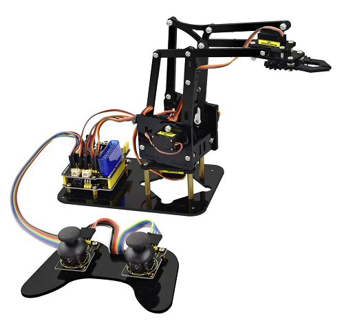
Kit Overview
How to DIY a robotic arm to complete multiple movements? Cool.With this keyestudio robotic arm kit, you are able to DIY your own controllable mechanical arm using ARDUINO microcontroller. It uses REV4 and 2 JoyStick modules to control the angle degree of 4 servos.
When DIY this 4DOF robot arm kit, you could get everything needed for arm installation and debugging.
There are 3 controlling methods are as follows:
1) Controlling through Wired JoyStick (included in the kit);
2) Phone Bluetooth Controlling (note: HC-06 Bluetooth module Not Included, only provide the test code for Bluetooth and APP for Android phone);
3) Wireless PS2 JoyStick Control (PS2 JoyStick module Not Included, we only provide the test code.)
You are able to get all related information in the Arm kit.
Take your brain on an inspiring journey through the world of programming. Get started now!
Kit Features
You can check out these features:
- Detailed installation instructions
- Detailed debugging methods, starting Arduino from entry.
- Three controlling methods: Wired JoyStick Control; Phone Bluetooth Control; Wireless PS2 JoyStick Control.
The parameters of keyestudio TB6612FNG motor/servo drive expansion board are as follows:
- VIN voltage: VIN = DC 7-15V
- VIN current: 5A
- Two-way 5V output: 5V/3A
- TB6612FNG: VIN input DC 7-15V; average drive current 1.2A; peak current 3.2A
- PS2 interface: compatible with Sony PS2 receiver, can be plugged directly into the expansion board.
- Dimensions: 73*53.34mm
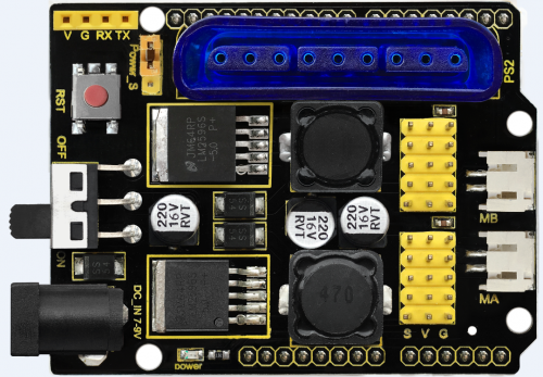
Part List
You can see a pretty beautiful packaging box for the arm kit, and inside the packaging you will find all the parts and screws listed below.
Please tear off the protective film on the acrylic board before mounting the kit
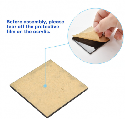
| No. | Component | Quantity | Picture |
|---|---|---|---|
| 1 | Keyestudio REV4 Main Board | 1 | 
|
| 2 | keyestudio TB6612FNG motor/servo drive shield | 1 | 
|
| 3 | MeArm T=3MM Black Acrylic panels | 1 | 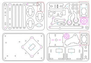
|
| 4 | MeArm T=3MM Black Acrylic handle | 1 | 
|
| 5 | MeArm Black ABS Cylindrical holder Diameter 42mm | 1 | 
|
| 6 | Black 180° Servo | 4 | 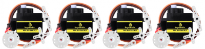
|
| 7 | Keyestudio Bluetooth Module-(HC-06) | 1 | |
| 8 | Keyestudio Joystick Module | 2 | 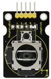
|
| 9 | 3D PS2 Joystick cap | 2 | 
|
| 10 | Yellow-black handle 3*40MM Phillips Screwdriver | 1 | |
| 11 | Galvanized M2+M3 2mm thin double-headed small wrench | 1 | |
| 12 | M3*6MM round-head cross screw | 12 | |
| 13 | M3*10MM round-head cross screw | 22 | 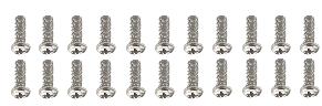
|
| 14 | M3*14MM flat-head screw | 2 | |
| 15 | M3*12MM round-head cross screw | 12 | 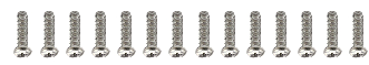
|
| 16 | M3*24+6MM copper pillar | 4 | 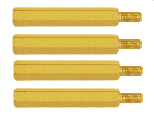
|
| 17 | M3*6mm+6mm copper pillar | 10 | 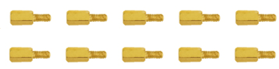
|
| 18 | M3 Stainless steel Hex Nut | 22 | 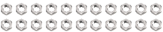
|
| 19 | M3 hexagon Lock Nut | 24 | |
| 20 | M1.2x5MM Phillips tapping screw | 8 | 
|
| 21 | M2x5MM Phillips tapping screw | 10 | 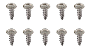
|
| 22 | M3 304 Stainless steel flat washer 3*7*0.5MM | 10 | |
| 23 | M2x8MM Phillips tapping screw | 2 | |
| 24 | M3*16MM flat-head screw | 2 | 
|
| 25 | Male to female 10CM jumper wire | 4 | |
| 26 | female to female 50CM jumper wire | 10 | |
| 27 | Black 3*100MM cable ties | 1 | |
| 28 | 18650 dual-cell battery case with plug lead 15CM | 1 | 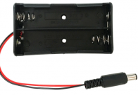
|
Assembly Guide
Follow the assembly steps below to build your own robot arm.
Step1: Begin with the Baseplate Assembly
(1) Firstly, you should prepare the components as follows:
- M3*30+5MM single-pass copper pillar *4
- M3*6mm+6mm single-pass copper pillar *4
- M3 Hex Nut *8
- Black Acrylic plate *1
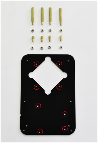
Then, screw the copper pillars with M3 hex nuts on the black Acrylic baseplate.
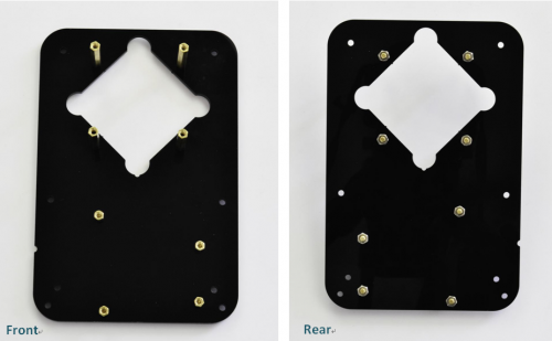
(2) Then install the control board, and prepare the components as follows:
- M3*6MM round-head screw *3
- Keyestudio REV4 board *1
- keyestudio TB6612FNG motor shield *1
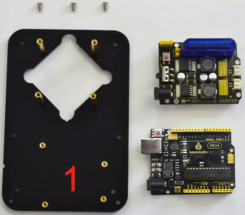
Firstly, screw the REV4 board on the pillar using three M3*6MM round-head screws.
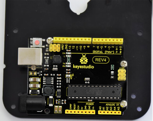
Then stack the motor drive shield onto the REV4 board.
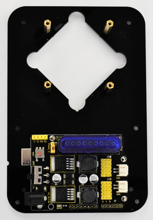
(3) Completed the above assembly, let’s mount the Pivot Servo Plate onto the base.
- M3*12MM round-head screw *2
- M3 hex lock Nut *2
- Black 180° servo *1
- Acrylic plate * 4
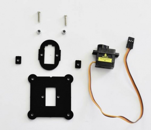
Note: before install the servo, should set the servo angle to 80 degrees.
To set the servo angle, first connect the servo to A0 of motor shield, upload the code below to REV4 board, powered on, press the reset button, servo will rotate to 80°.

Code for 80° Servo:
int servopin=A0;//Define digital interface A0 to connect servo steering gear signal line
int myangle;     //Define angle variables
int pulsewidth; //Define pulse width variables
void setup()
{
pinMode(servopin,OUTPUT); //Set steering gear interface as Output
}
void servopulse(int servopin,int myangle) //Define Function
{
pulsewidth=(myangle*11)+500; //Converts the Angle to a pulse width value of 500 - 2480
digitalWrite(servopin,HIGH); //The steering gear interface level is high
delayMicroseconds(pulsewidth); //The microsecond number of the delay pulse width value
digitalWrite(servopin,LOW); //Turn the steering gear interface level to low
delay(20-pulsewidth/1000);
}
void loop()
{
servopulse(servopin,80); //Set steering gear Angle
}

//0 Degree Code:
//		servopulse(servopin,0);
//80 Degree Code:
//		servopulse(servopin,80);
//180 Degree Code:
//		servopulse(servopin,180);
Note:
Set well the servo angle and complete the below servo base plate assembly, power off the servo to avoid the angle error and make sure the servo can rotate freely. Don’t over-tighen the screws.
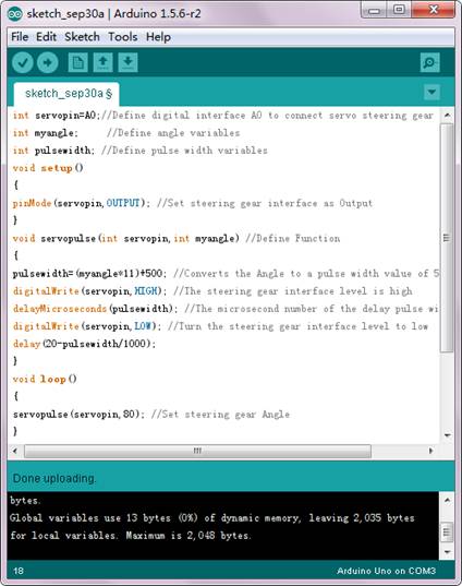
Adjusted well the servo motor, start to install the Servo Base Plate. Follow the marks.
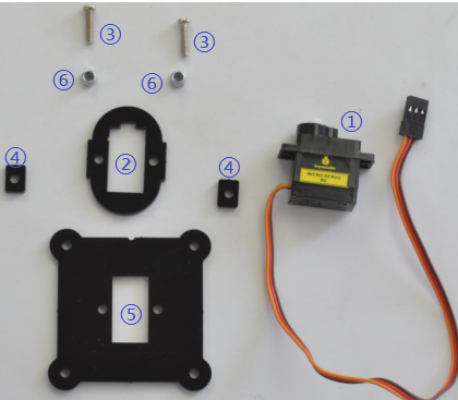
Firstly mount the acrylic plate ② to the servo motor.
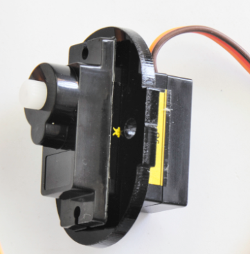
Then mount the two acrylic plates ④ to the servo using two M3*12MM round-head screws.
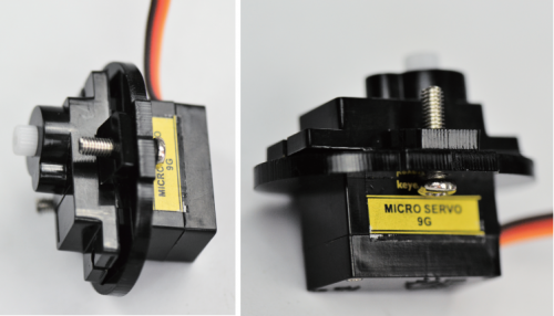
After that, screw the acrylic plate ⑤ to the servo using two M3 hex lock Nuts⑥.
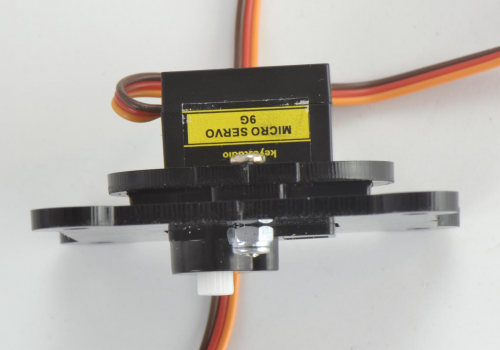
You should get the detailed view shown below (pay close attention to red mark).
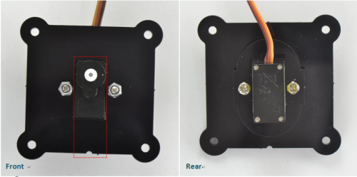
You should get the complete Servo Base Part.
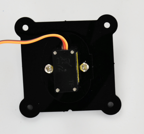
(4) Now you should install the Servo Base part to the Base Plate:
- M3*6MM round-head hex screw *4
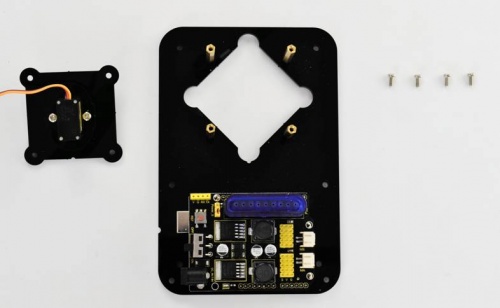
Install the Servo plate to the Base Plate using four M3*6MM round-head hex screws.
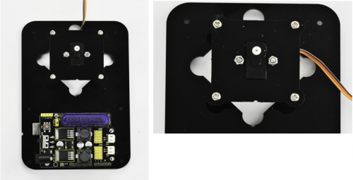
Step2: Assemble Arm Middle Parts
(1) In the following section, assemble the Left Arm Servo Plate. Prepare:
- M3*12MM round-head screw *2
- M3 hex lock nut *2
- M2x5MM Phillips tapping screw *1
- M2x8MM Phillips tapping screw *1
- Black 180° servo *1
- White servo mount *1
- Acrylic plate *5
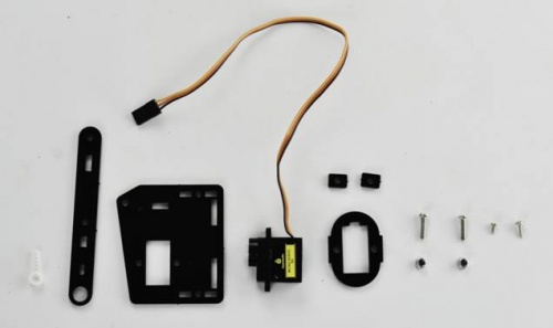
Note: before install the servo plate, should set the servo angle to 180 degrees. The method is the same as 80° servo settings mentioned above. You just need to change the servopulse(servopin,80) into servopulse(servopin,180) in the code.
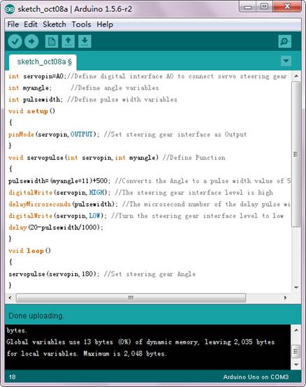
Now assemble the Left Arm Servo Plate as below.
(pay close attention to servo direction, rocker connected to servo and marked position)
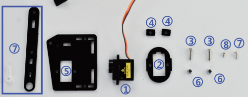
Firstly mount the acrylic plate ② to the Left servo motor.
Second, mount the two acrylic plates ④ to the servo using two M3*12MM round-head screws③. You can get the Left servo plate shown below.
Then screw the Left servo plate to acrylic plate ⑤ using two M3 hex lock Nuts⑥. Get the Left servo base plate shown below.
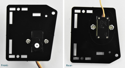
After that, screw the acrylic plate joint and white servo mount ⑦ to the Left servo base plate using a M2x8MM tapping screw and a M2x5MM tapping screw⑧.
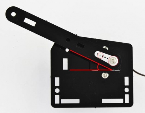
Finally you should get the complete Left Arm Servo Plate. Shown below.
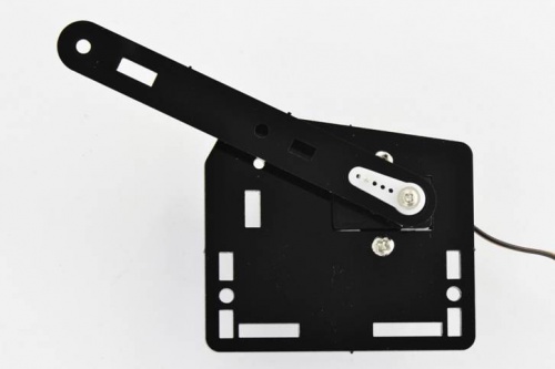
(2) We will now attach a servo mount to the Arm Bottom Plate.
- M2x8MM Phillips tapping screw *2
- White servo mount *1
- Acrylic bottom plate *1
- Black Cylindrical holder *1
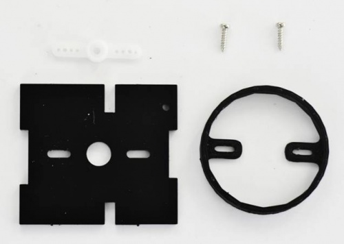
Fix the white servo mount and black Cylindrical holder on the acrylic plate using two M2x8MM Phillips tapping screws.
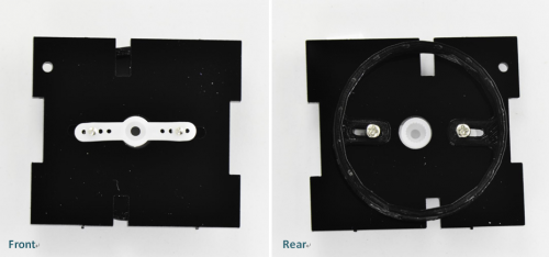
(3) Completed the above assembly, move on to the Right Arm Servo Plate.
- M3*12MM round-head screw *2
- M3 hex lock nut *2
- M2x5MM Phillips tapping screw *1
- M2x8MM Phillips tapping screw *1
- Black 180° servo *1
- White servo mount *1
- Black Acrylic plate *5
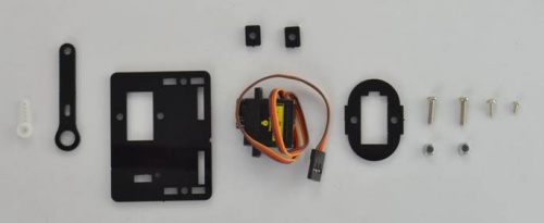
Note: before install the servo, should set the servo angle to 0 degrees.
The method is the same as 80° servo settings mentioned above.
You just need to change the servopulse(servopin,80) into servopulse(servopin,0) in the code.
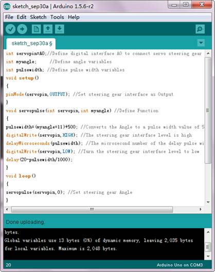
Now assemble the Right Arm Servo Plate as below.
(pay close attention to servo direction, rocker connected to servo and marked position)
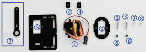
Firstly mount the acrylic plate ② to the Right servo motor.
Second, mount the two acrylic plates ④ to the servo using two M3*12MM round-head screws③.
Then screw the Right servo plate to acrylic plate ⑤ using two M3 hex lock Nuts⑥.
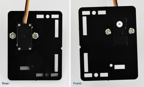
After that, screw the short acrylic plate joint and white servo mount ⑦ to the Right servo motor using a M2x8MM tapping screw and a M2x5MM tapping screw⑧.
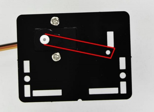
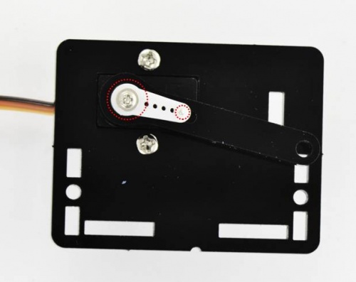
Finally you should get the complete Left Servo Plate. Shown below.
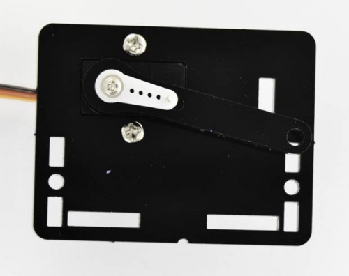
(4) Next install the Servo Wrist Joint.
- M3*10MM round-head screw *1
- M3 hex lock nut *1
- Acrylic plate*2
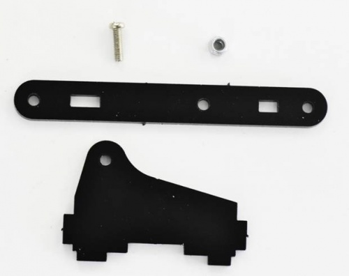
Fix the two Acrylic plates together using a M3*10MM screw and a M3 lock nut.
You can get the Wrist Joint Plate shown below.
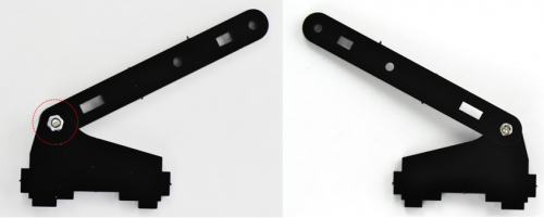
(5) The above parts are installed well. Mount the Wrist Joint and Left Arm Servo Plate together.
- M3*10MM round-head screw *2
- M3 hex nut *2
- Acrylic plate*1
- Left Arm Servo Plate
- Wrist Joint Plate
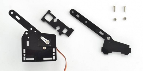
Install both Left Arm Servo Plate and Wrist Joint plate to a single acrylic plate using two M3 hex nuts and two M3*10MM round-head screws.
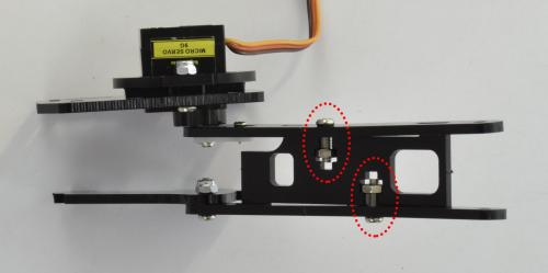
You should get the complete parts shown below.
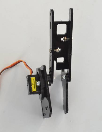
(6) Complete the whole Arm Base Parts.
- M3*10MM round-head screw *4
- M3 hex nut *4
- Acrylic plate *2
- Arm Bottom Plate⑥
- Left Arm Servo Plate①
- Right Arm Servo Plate⑦
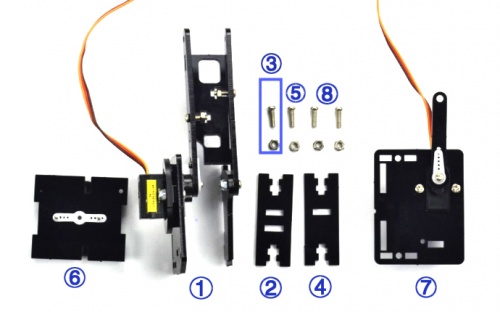
Mount the Acrylic plate ② to Left Arm Servo Plate ① using a M3*10MM round-head screw and a M3 hex nut③.
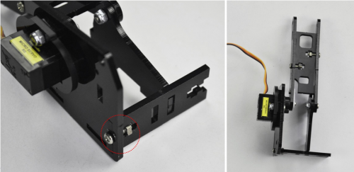
Then screw another Acrylic plate ④ to Left Arm Servo Plate ① using a M3*10MM round-head screw and a M3 hex nut.
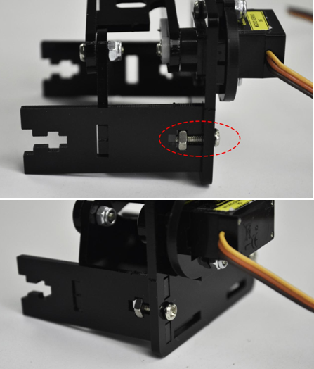
After that, snap the Arm Bottom Plate ⑥ between the both side plate of Arm BasePlate.
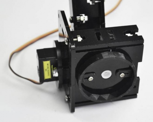
At last, mount the Right Arm Servo Plate ⑦ to the BasePlate using two M3*10MM round-head screws and two M3 hex nuts.
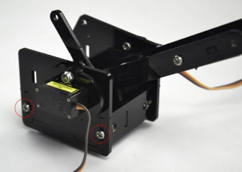
With this step completed, the Arm Base Parts is really starting to take shape!
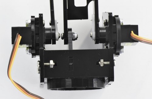
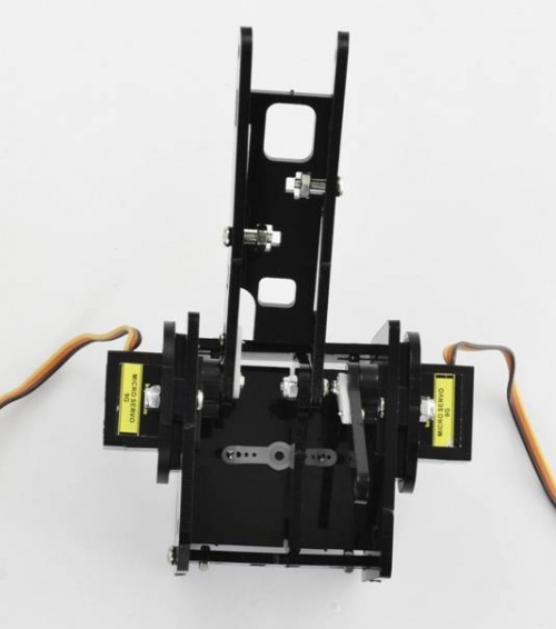
(7) Now we should install the Wrist Joint Connector between the Left and the Right Wrist Joint.
- M3*10MM round-head screw *7
- M3*12MM round-head screw *1
- M3 hex lock nut *8
- Acrylic plate*6
- Arm Base Parts①
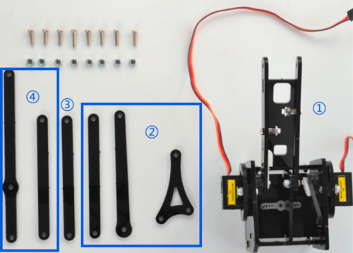
Fix well the Acrylic plates②③④.
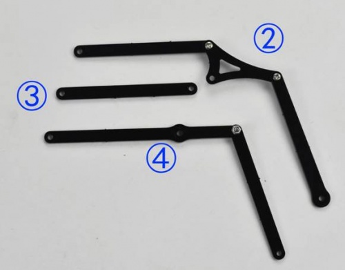
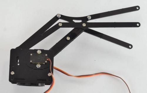
Then screw them to Arm Base Parts① with 7 M3*10MM screws, a M3*12MM screw and 8 M3 lock nuts.
Don’t over-tighten the screws as they serve as pivot points to allow the robot arm to move.
(Note: only red circle there use the M3*12MM screw, other wrist joints all use M3*10MM screw.)
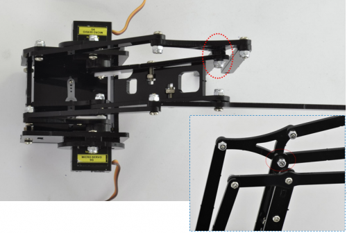
Installed well.
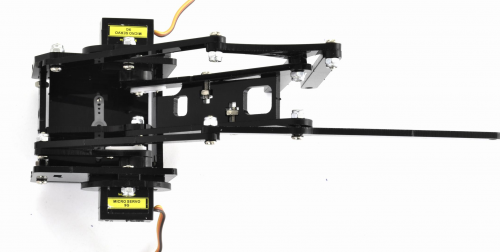
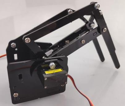
Step3: Assemble the Claw Servo Plate
(1) We are now on the final stretch, it’s time to work on the claw.
- M3*16MM flat-head screw *2
- M3*14MM flat-head screw *2
- M3 hex lock nut *4
- Black 180° servo *1
- Acrylic plate*6
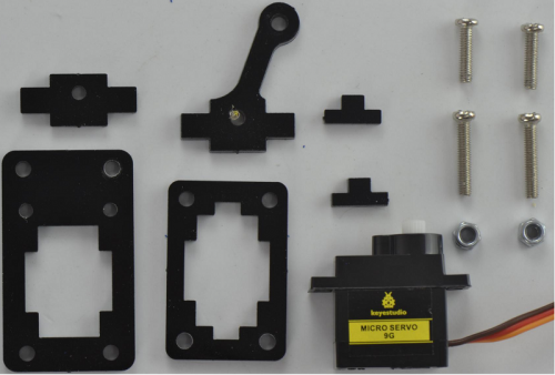
Note: before install the claw servo motor, should set the servo angle to 0 degrees.
The method is the same as 80° servo settings mentioned above.
You just need to change the servopulse(servopin,80) into servopulse(servopin,0) in the code.
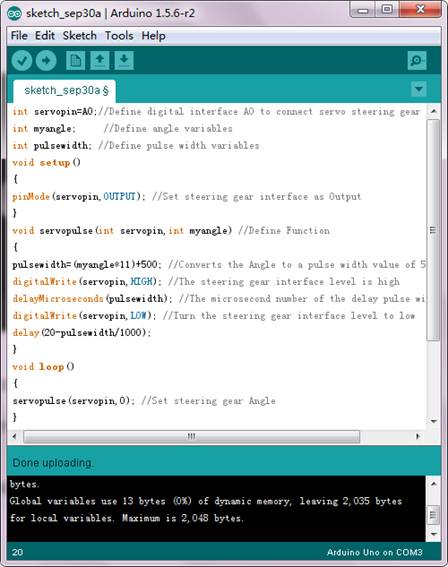
We will start by mounting the Claw Servo Motor Plate.
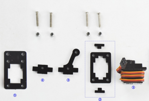
Fix well the Acrylic Plates②③④, and insert the servo motor. Get the servo plate shown below.
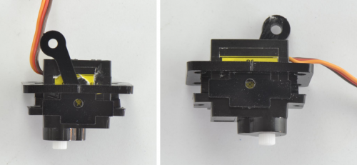
Then tighten a Acrylic Plate ⑤ to the above servo plates using two M3*16MM flat-head screws and two M3*16MM round-head screws and four M3 hex nuts.
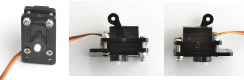
(2) Next is to install the Gripper Plate.
- M1.2x5MM Phillips tapping screw *4
- M2x5MM Phillips tapping screw *4
- White servo mount *1
- Gripper Acrylic plate *3
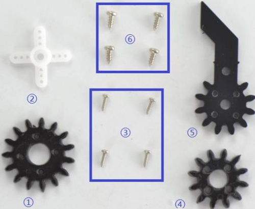
Firstly fix the white servo mount ② onto acrylic plate ① using four M1.2x5MM tapping screws③.
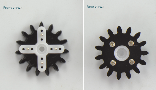
Then fix the acrylic plate ④ onto another longer acrylic plate ⑤ using four M2x5MM tapping screws.
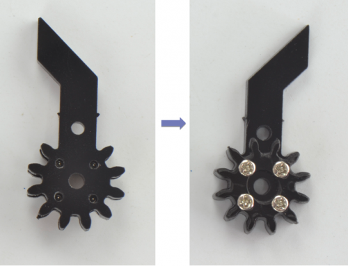
(3) Mount the grippers onto the claw servo plate.
- M3*12MM round-head screw *2
- M3 hex lock nut *2
- M3 flat washer *7
- Servo screw *1①
- Claw servo plate②
- Gripper plate③
- Gripper plate④
- Gripper Acrylic plate*1⑤
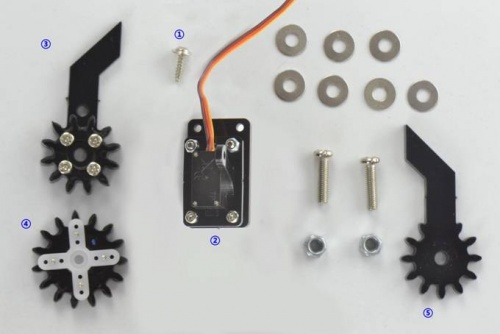
Place the four flat washers onto a M3*12MM round-head screw connected to the Claw servo plate.
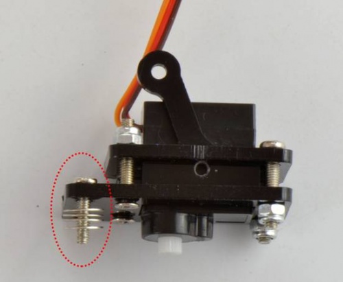
Then fix a M3 hex lock nut to the Gripper plate③. Next, place the Gripper plate onto Claw servo plate.
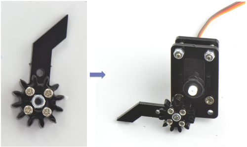
After that, place another Gripper plate⑤ onto Claw servo plate using 3 flat washers and a M3*12MM round-head screw.
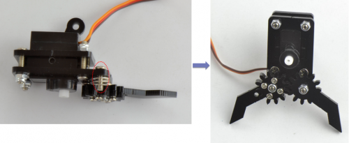
Finally, screw the Gripper plate ④ onto the shaft of servo motor with a servo screw.
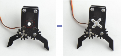
Claw servo plate completed!
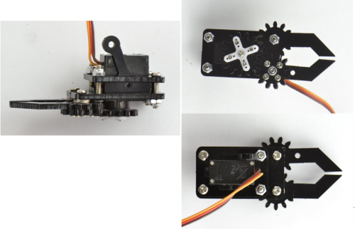
Step4: Final Assembly
(1) Now we will assemble all the finished parts together
- M3*10MM round-head screw *3
- M3 hex lock nut *1
- M2x5MM tapping screw *1
- Servo Base Plate①
- Arm Middle Parts②
- Claw Servo Plate③
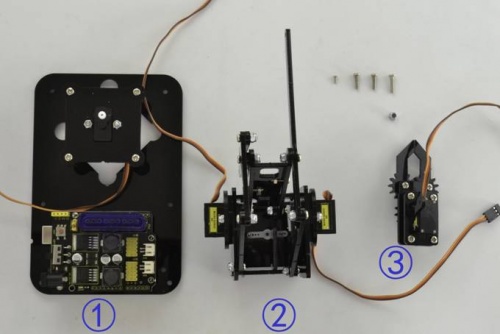
Mount the Claw Servo Plate ③ to Arm Middle Parts ② using three M3*10MM round-head screws and a M3 hex lock nut.
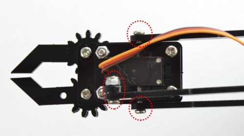
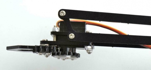
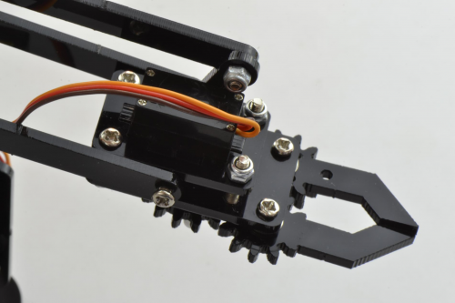
After that, screw them to Servo Base Plate ① using a M2x5MM tapping screw.
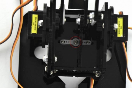
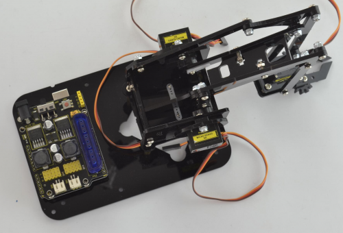
The robot arm kit is nearly complete! It’s now time to connect the servo to drive shield.
Hookup Guide:

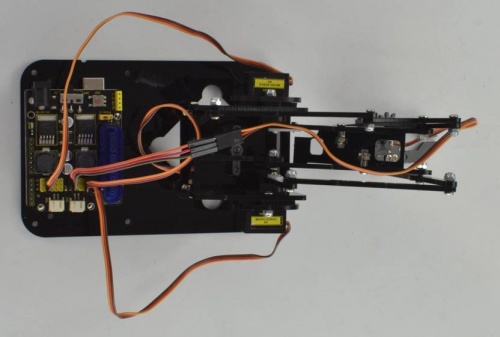
Step5: Assemble the Joystick Control Plate
(1) The last step is to assemble the Joystick control plate
- M3*6MM round-head screw *4
- M3*6+6mm single-pass copper pillar *6
- M3 hex nut *6
- Joystick module *2
- Black Joystick plate *1
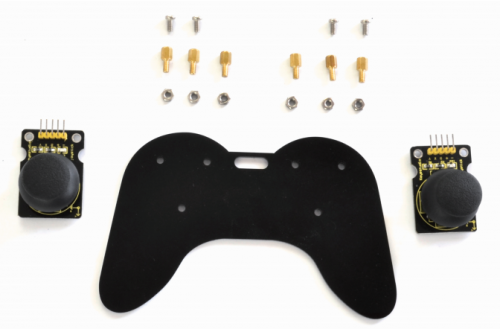
Mount 6 single-pass copper pillars onto Joystick plate with 6 M3 hex nuts.
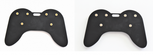
Then screw the two Joystick modules onto the Acrylic plate using four M3*6MM round-head screws.
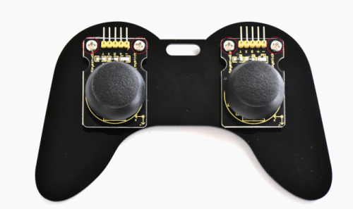
(2) Finally connect the Joystick module to drive shield using female-to-female jumper wires.
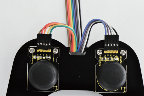
Hookup Guide:
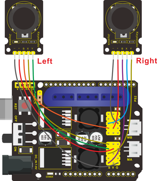
Congrats! Your robot arm kit is complete!
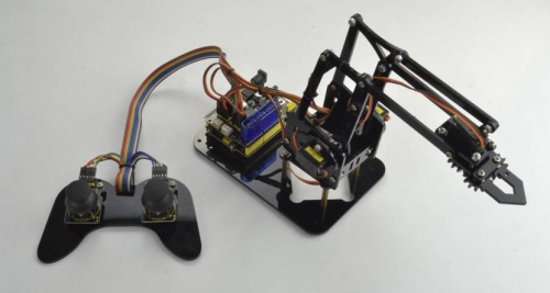
Done wiring, power and program everything up to give your robot arm kit a try!
Robot Arm Projects
Project 1: Getting Started with ARDUINO
1) Core Part of Robot
When it comes to using the REV4 as core of our robot, the REV4 is the best board to get started with electronics and coding. If this is your first experience tinkering with the platform, the REV4 is the most robust board you can start playing with.
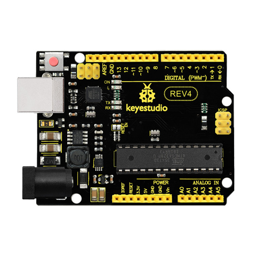
Well, let’s at first have a look at this REV4 board.
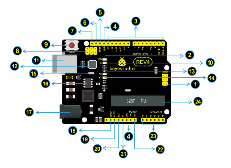
| USB Connection
Arduino board can be powered via USB connector. Or you can program the board via the USB port. |
|
| DC Power Jack
Arduino board can be supplied with power from the DC power jack |
|
| Voltage Regulator
To control the voltage provided to the Arduino board, as well as to stabilize the DC voltage used by the processor and other components. |
|
| Crystal Oscillator
How does Arduino calculate time? by using a crystal oscillator. |
|
| Arduino RESET
You can reset your Arduino board, for example, start the program from the very beginning. Firstly, use the RESET button(17). Or you can connect an external reset button to Arduino pin 5 labeled RESET |
|
| Pin Header(3.3V,5V,GND,Vin
|
|
| Analog Pins
Arduino REV4 board has 6 analog inputs, labeled A0 through A5. These pins can read the signal from analog sensors (such as humidity sensor or temperature sensor), and convert it into the digital value that can read by microcontrollers) |
|
| Microcontroller
Each Arduino board has its own microcontroller. You can regard it as the brain of your board. |
|
| ICSP (In-Circuit Serial Programming) Header
In most case, ICSP is the AVR, an Arduino micro-header consisting of MOSI, MISO, SCK, RESET, VCC, and GND.It is often called the SPI (serial peripheral interface) and can be considered an «extension» of the output.In fact, slave the output devices under the SPI bus host. |
|
| Power LED Indicator
Powering the Arduino, LED on means that your circuit board is correctly powered on. If LED is off, connection is wrong. |
|
| TX and RX LED
Onboard you can find two labels: RX(receive ) and TX (transmit) |
|
| Digital I/O
Arduino REV4 has 14 digital input/output pins (of which 6 can be used as PWM outputs). These pins can be configured as digital input pin to read the logic value (0 or 1). Or used as digital output pin to drive different modules like LED, relay, etc. The pin labeled “〜” can be used to generate PWM. |
|
| AREF
Reference voltage( 0-5V) for the analog inputs. Used with analogReference(). |
Installing Arduino IDE
When you get the REV4 development board, first you should install the software and driver of Arduino. You can see all the Arduino software versions from the link below:
https://www.arduino.cc/en/Main/OldSoftwareReleases#1.5.x
Or you can browse the ARDUINO website at this link, https://www.arduino.cc, pop up the following interface.

Then click the SOFTWARE on the browse bar, you will have two options ONLINE TOOLS and DOWNLOADS.

Click DOWNLOADS, it will appear the latest software version of ARDUINO 1.8.5 shown as below.

In this software page, on the right side you can see the version of development software for different operating systems. So ARDUINO has a rather powerful compatibility. You should download the software that is compatible with the operating system of your computer.
In our project, we will take WINDOWS system as an example here. There are also two options under Windows system, one is installed version, the other is non-installed version.
For simple installed version, first click Windows Installer, you will get the following page.
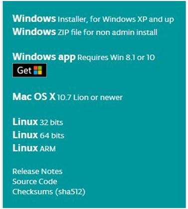

This way you just need to click JUST DOWNLOAD, then click the downloaded file to install it.
For non-installed version, first click Windows ZIP file, you will also get the pop-up interface as the above figure.
Click JUST DOWNLOAD, and when the ZIP file is downloaded well to your computer, you can directly unzip the file and then click the icon of ARDUINO program to start it.
Installing Arduino (Windows)
Install Arduino with the exe. Installation package
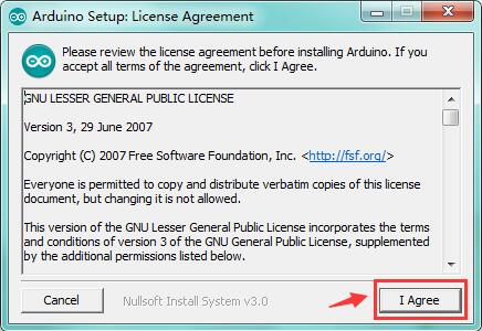
Click“I Agree”to see the following interface.
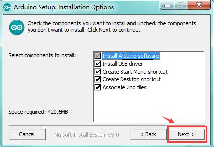
Click “Next”. Pop up the interface below.
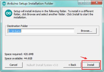
You can press Browse… to choose an installation path or directly type in the directory you want.
Then click “Install” to initiate installation.
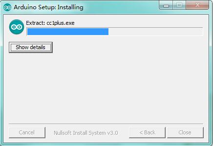
Wait for the installing process, if appear the interface of Window Security, just continue to click Install to finish the installation.
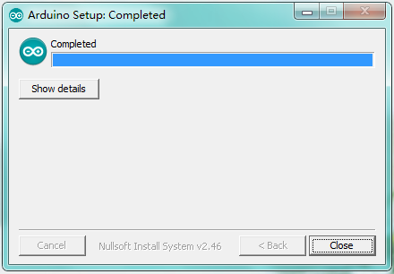
All right, up to now, you have completed the Arduino setup! The following icon will appear on your PC desktop.

Double-click the icon of Arduino to enter the desired development environment shown as below.
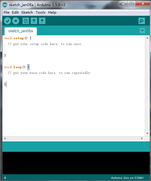
Installing Driver
Next, we will introduce the driver installation of REV4 development board. The driver installation may have slight differences in different computer systems. So in the following let’s move on to the driver installation in the WIN 7 system.
The Arduino folder contains both the Arduino program itself and the drivers that allow the Arduino to be connected to your computer by a USB cable. Before we launch the Arduino software, you are going to install the USB drivers.
Plug one end of your USB cable into the Arduino and the other into a USB socket on your computer.
When you connect REV4 board to your computer at the first time, right click the icon of your “Computer” —>for “Properties”—> click the “Device manager”, under “Other Devices”, you should see an icon for“Unknown device” with a little yellow warning triangle next to it. This is your Arduino.
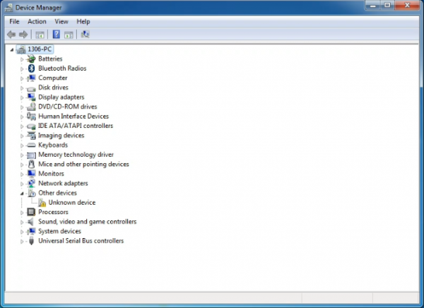
Then right-click on the device and select the top menu option (Update Driver Software…) shown as the figure below..
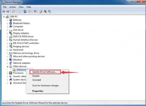
It will then be prompted to either “Search Automatically for updated driversoftware” or “Browse my computer for driver software”. Shown as below. In this page, select “Browse my computer for driver software”.
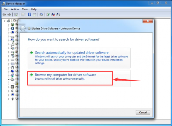
After that, select the option to browseand navigate to the “drivers” folder of Arduino installation.
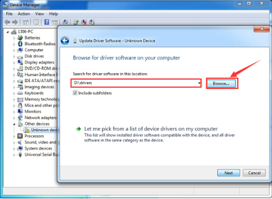
Click “Next” and you may get a security warning, if so, allow the software to be installed. Shown as below.
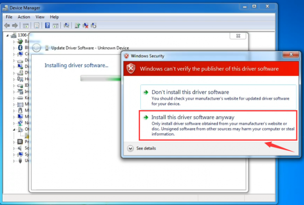
Once the software has been installed, you will get a confirmation message. Installation completed, click “Close”.
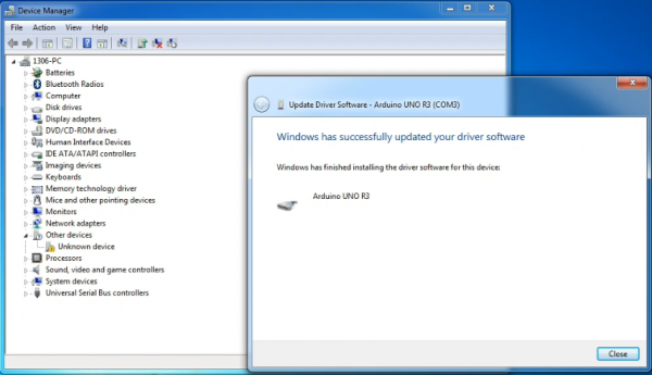
Up to now, the driver is installed well. Then you can right click “Computer” —>“Properties”—>“Device manager”, you should see the device as the figure shown below.
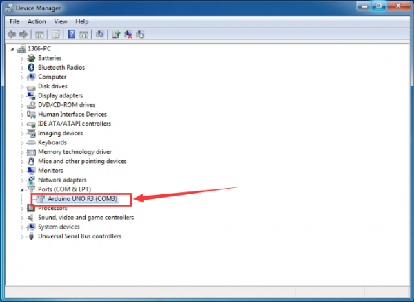
2) Example Use of ARDUINO IDE
STEP 1: Open Arduino
In the previous, we have introduced the driver installation of REV4 development board. So this time let’s first have basic understanding of the development environment of ARDUINO. After that, you will learn how to upload the program to Arduino board.
First of all, open the unzipped folder of ARDUINO development software and click icon of ARDUINO to open the software, as the figure shown below.
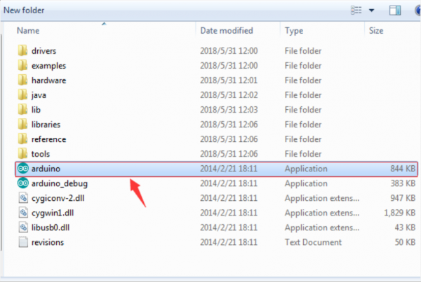
STEP 2: Build Projects
When open the Arduino software, you will have two options as below:
- Build a new project
- Open an exiting project example
If you want to build a new project, please select “File”→then click “New”, you will see the software interface as follows.
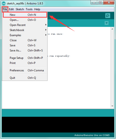
![]()
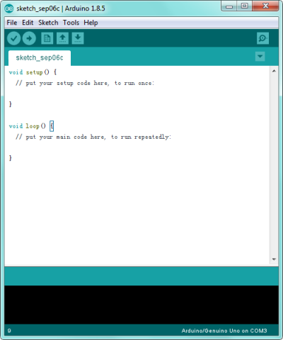
If you want to open an example project, please select File→Example→Basics→Blink. Shown below.
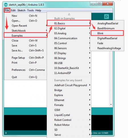
![]()
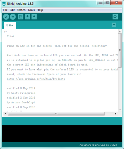
STEP 3: Select Arduino Board
On the Arduino software, you should click Tools→Board , select the correct board. Here in our tutorial we should select Arduino UNO. Shown as below.
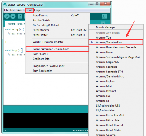
STEP 4: Select Serial Port
If you are not sure which port is correct, at first directly open the Control Panel of your computer, then click to open Device Manager, you can check the COM port here. Shown as below.
Then you should click Tools→Serial Port. It may be COM3 or higher (COM1 and COM2 are usually reserved as hardware serial port).
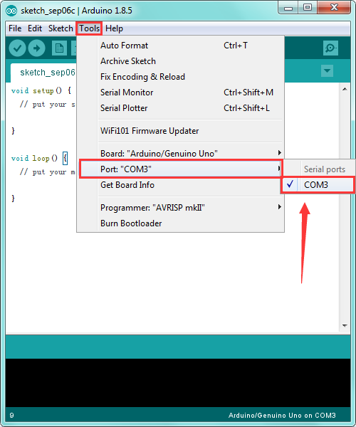
STEP 5: Upload the Code to Your Board
Before showing you how to upload the code to your board, first of all let me introduce the function of each icon on the Tool bar of Arduino IDE. Look at the picture showed below.
![]()
| Check the code for errors | |
| Upload the current Sketch to the Arduino | |
| Create a new blank Sketch | |
| Show a list of Sketches | |
| Save the current Sketch | |
| Display the serial data being sent from the Arduino |
Project 2: Joint Rotation and Pin Control
1)Joint Rotation and Servo Angle Settings
| Name | 0° | 180° |
|---|---|---|
| Servo 1(baseplate) | Rotate toward the rightmost | Rotate toward the leftmost |
| Servo 2(right side) | Rocker arm connected to Servo 2 draws back | stretch out |
| Servo 3(left side) | Rocker arm connected to Servo 3 stretches out | draw back |
| Servo 4(clamp claw) | closed | opened |
2)Pin Control
| Name | IO Pin |
|---|---|
| Servo 1 (baseplate) | A1 |
| Servo 2 (right side) | A0 |
| Servo 3(left side) | 6 |
| Servo 4(clamp claw) | 9 |
| Right Joystick X | A2 |
| Right Joystick Y | A5 |
| Right Joystick Z (key) | 7 |
| Left Joystick X | A3 |
| Left Joystick Y | A4 |
| Left Joystick Z | 8 |
| D1/DAT of PS2 | 12 |
| D0/CMD of PS2 | 10 |
| CE/SEL of PS2 | 11 |
| CLK of PS2 | 13 |
Project 3: JoyStick Controlled Robot Arm
1)Servo Control
How to adjust the Servo Angel
Hookup Guide:
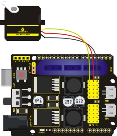
Code to Note:
In the previous assembly, we have set the square wave and servo angle. So we should use the servo libraries to control the angle of each servo. The test result is the same. Before using, place the Servo folder inside the libraries folder of Arduino IDE directory, then open the Arduino IDE, and the libraries are able to use.
You can download all the libraries for test code from the link:
https://drive.google.com/open?id=1HtyzuNT59Av5QP8nO0kv6syQsoK1fUOw
Test Code 1:
#include <Servo.h>
Servo myservo;  // create servo object to control a servo

void setup()
{
  Serial.begin(9600);
  delay(1000);
}

void loop()
{
  myservo.attach(A0);  // modify each pin to adjust
  myservo.write(0);  // angle value
  delay(1000);
}
Test Result:
Stack the drive shield onto REV4 board and connect the servo motor, upload well the code. Powered on, press the reset button, the servo will automatically rotate to 0°.
Automatic Turning
Description:
In the previous section, you have learned to set the Servo angle. In fact, we just need to continually change the angle of 4 Servo motors, thus make the 4DOF robot arm operate different motions.
Hookup Guide:

Test Code 2:
#include <Servo.h>
Servo myservo1;  // create servo object to control a servo
Servo myservo2;
Servo myservo3;
Servo myservo4;
int pos1=80, pos2=60, pos3=130, pos4=0;

void setup()
{
  myservo1.attach(A1);  // attaches the servo on pin 9 to the servo object
  myservo2.attach(A0);
  myservo3.attach(6);
  myservo4.attach(9);

  myservo1.write(pos1);
  delay(1000);
  myservo2.write(pos2);
  myservo3.write(pos3);
  myservo4.write(pos4);
  delay(1500);
}

void loop()
{
  // turn right
  for(pos1;pos1>0;pos1--)
  {
    myservo1.write(pos1);
    delay(5);      // delay 5ms(used to adjust the servo speed)
  }
  delay(1000);

  // open the claw
 for(pos4;pos4<100;pos4++)
 {
   myservo4.write(pos4);
 }
  delay(1000);

  // right servo rotates to 100 degrees
  for(pos2;pos2>50;pos2--)
  {
    myservo2.write(pos2);
    delay(5);
  }
  // left servo rotates to 5 degrees
  for(pos3;pos3>50;pos3--)
  {
    myservo3.write(pos3);
    delay(5);
  }
  delay(1500);

  // close the claw
  for(pos4;pos4>0;pos4--)
  {
    myservo4.write(pos4);
  }
  delay(1000);

  // left servo rotates to100 degrees, rocker arm lifts.
  for(pos3;pos3<120;pos3++)
  {
    myservo3.write(pos3);
    delay(5);
  }
  delay(1000);

  // turn to left
  for(pos1;pos1<180;pos1++)
  {
    myservo1.write(pos1);
    delay(5);
  }
  delay(1000);

  // Lower the arm
  for(pos3;pos3>50;pos3--)
  {
    myservo3.write(pos3);
    delay(5);
  }
  delay(1000);

  // open the claw
  for(pos4;pos4<100;pos4++)
  {
    myservo4.write(pos4);
  }
  delay(1000);

  // lift up the arm
  for(pos3;pos3<120;pos3++)
  {
    myservo3.write(pos3);
    delay(5);
  }
  delay(1000);

  // close the claw
  for(pos4;pos4>0;pos4--)
  {
    myservo4.write(pos4);
  }
  delay(1000);
}
Test Result:
Stack the drive shield onto REV4 board and connect the servo motor, upload well the code. Powered on, press the reset button, the robot arm will realize a cyclic motion. Turn to the right, stretch out the arm, lower, the claw is clamped; then the arm is retracted, raised, turned to the left, stretched out, lowered and the claw is opened.
After that, return to the right and continue to repeat the motion.
2)Read the JoyStick Value
Description:
The sensor’s pin X, Y are for analog sensor, so directly read the measured analog value. Pin Z is a digital button, first should set the pin to Input status and then read the measured value 1 (pressed down) or 0 (not press). Check out the value printed on the serial monitor.
Hookup Guide:
Test Code 3:
const int right_X = A2; // define the right X pin to A2
const int right_Y = A5; // define the right Y pin to A5
const int right_key = 7; //define the right key pin to 7(that is the value Z)

const int left_X = A3; //define the left X pin to A3
const int left_Y = A4;  // define the left Y pin to A4
const int left_key = 8; //define the left key pin to 8(that is the value Z)

void setup()
{
  pinMode(right_key, INPUT);   // set the right/left key to INPUT
  pinMode(left_key, INPUT);
  Serial.begin(9600); //  set the baud rate to 9600
}

void loop()
{
  int x1,y1,z1;  // define the variable, used to save the joystick value it reads
  int x2,y2,z2;

  x1 = analogRead(right_X); // read the value of right X
  y1 = analogRead(right_Y);  // read the value of right Y
  z1 = digitalRead(right_key);  //// read the value of right Z

  x2 = analogRead(left_X);  // read the value of left X
  y2 = analogRead(left_Y);  // read the value of left Y
  z2 = digitalRead(left_key);  // read the value of left Z

  Serial.print("right_X = "); // on the serial monitor, print out right_X =
  Serial.println(x1 ,DEC);  // print out the value of right X and line wrap
  Serial.print("right_Y = ");
  Serial.println(y1 ,DEC);
  //Serial.print("right_key = ");
  //Serial.println(z1 ,DEC);
 // Serial.println("**********right**********");
  /*Serial.print("left_X = ");
  Serial.println(x2 ,DEC);
  Serial.print("left_Y = ");
  Serial.println(y2 ,DEC);
  Serial.print("left_key = ");
  Serial.println(z2 ,DEC);
  Serial.println("*********left***********");*/
  delay(200);
}
Test Result:
Hook it up and upload well the code. Connect the REV4 to computer using a USB cable, then open the serial monitor and set the baud rate to 9600, you should see the analog value of the right Joystick pin X,Y.
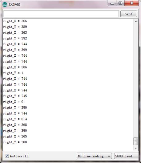
3)Dual-JoyStick Controlling
Description:
In the previous section, we have introduced how to use 4 Servo to control the robot arm. Next, combine those two experiments. Use two Joystick modules to control 4DOF robot arm realize different motions.
At first, set the boot posture. The Joystick control is shown as below table.
| Right Joystick | Servo | Left Joystick | Servo |
|---|---|---|---|
| X1<50 | Servo 1 gradually reduces to 0° (push the right joystick to the right, the servo that controls the arm rotation turns right, and stops at 0° ) | X2<50 | Servo 4 gradually reduces to 0° (push the left joystick to the right, the claw is closed) |
| X1>1000 | Servo 1 gradually increases to 180° (push the right joystick to the left, the servo that controls the arm rotation turns left, and stops at 180° ) | X2>1000 | Servo 4 gradually increases to 180° (push the left joystick to the left, the claw opens) |
| Y1>1000 | Servo 2 gradually reduces to 0° ( that is, lift up the robot upper arm) | Y2>1000 | Servo 3 gradually reduces to 35° ( that is, stretch out the robot lower arm) |
| Y1<50 | Servo 2 gradually reduces to 180° ( that is, lower the robot upper arm) | Y2<50 | Servo 3 gradually increases to 180° ( that is, draw back the robot lower arm) |
Hookup Guide:
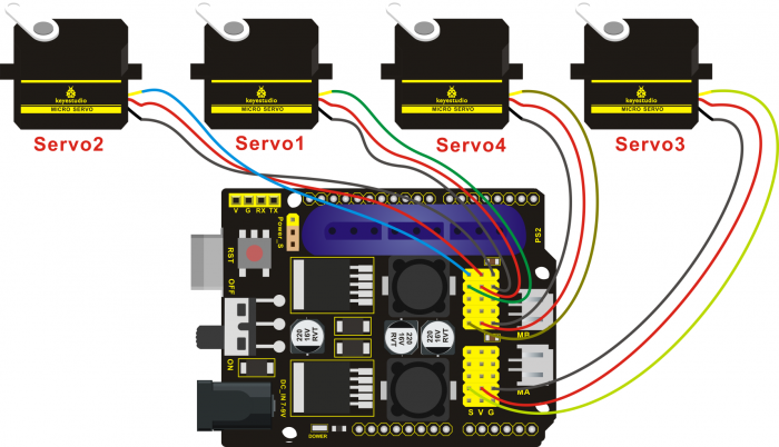
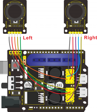
Test Code 4:
#include <Servo.h>  // add the servo libraries
Servo myservo1;  // create servo object to control a servo
Servo myservo2;
Servo myservo3;
Servo myservo4;

int pos1=80, pos2=60, pos3=130, pos4=0;  // define the variable of 4 servo angle,and assign the initial value (that is the boot posture angle value)

const int right_X = A2; // define the right X pin to A2
const int right_Y = A5; // define the right Y pin to A5
const int right_key = 7; // define the right key pin to 7(that is the value of Z)

const int left_X = A3; // define the left X pin to A3
const int left_Y = A4;  // define the left X pin to A4
const int left_key = 8; //define the left key pin to 8(that is the value of Z)

int x1,y1,z1;  // define the variable, used to save the joystick value it read.
int x2,y2,z2;


void setup()
{

  // boot posture
  myservo1.write(pos1);
  delay(1000);
  myservo2.write(pos2);
  myservo3.write(pos3);
  myservo4.write(pos4);
  delay(1500);

  pinMode(right_key, INPUT);   // set the right/left key to INPUT
  pinMode(left_key, INPUT);
  Serial.begin(9600); //  set the baud rate to 9600
}

void loop()
{
  myservo1.attach(A1);  // set the control pin of servo 1 to A1
  myservo2.attach(A0);  // set the control pin of servo 2 to A0
  myservo3.attach(6);   //set the control pin of servo 3 to D6
  myservo4.attach(9);   // set the control pin of servo 4 to D9

  x1 = analogRead(right_X); //read the right X value
  y1 = analogRead(right_Y);  // read the right Y value
  z1 = digitalRead(right_key);  //// read the right Z value

  x2 = analogRead(left_X);  //read the left X value
  y2 = analogRead(left_Y);  //read the left Y value
  z2 = digitalRead(left_key);  // read the left Z value
  //delay(5);  // lower the speed overall

  // claw
  zhuazi();
  // rotate
  zhuandong();
  // upper arm
  xiaobi();
  //lower arm
  dabi();
}

//claw
void zhuazi()
{
    //claw
  if(x2<50) // if push the left joystick to the right
  {
      pos4=pos4-2;  //current angle of servo 4 subtracts 2(change the value you subtract, thus change the closed speed of claw)
      //Serial.println(pos4);
      myservo4.write(pos4);  // servo 4 operates the action, claw is gradually closed.
      delay(5);
      if(pos4<2)  // if pos4 value subtracts to 2, the claw in 37 degrees we have tested is closed.
      {            //(should change the value based on the fact)
        pos4=2;   // stop subtraction when reduce to 2
      }
   }
  if(x2>1000) //// if push the left joystick to the left
  {
      pos4=pos4+8; // current angle of servo 4 plus 8(change the value you plus, thus change the open speed of claw)
      //Serial.println(pos4);
      myservo4.write(pos4); // servo 4 operates the motion, the claw gradually opens.
      delay(5);
      if(pos4>108)  // limit the largest angle when open the claw
      {
        pos4=108;
      }
  }
}
//******************************************************
 // turn
void zhuandong()
{
  if(x1<50)  // if push the right joystick to the right
  {
    pos1=pos1-1;  //pos1 subtracts 1
    myservo1.write(pos1);  // servo 1 operates the motion, the arm turns right.
    delay(5);
    if(pos1<1)   // limit the angle when turn right
    {
      pos1=1;
    }
  }
  if(x1>1000)  // if push the right joystick to the let
  {
    pos1=pos1+1;  //pos1 plus 1
    myservo1.write(pos1);  // arm turns left
    delay(5);
    if(pos1>180)  // limit the angle when turn left
    {
      pos1=180;
    }
  }
}

//**********************************************************/
//upper arm
void xiaobi()
{
    if(y1>1000) // if push the right joystick upward
  {
    pos2=pos2-1;
    myservo2.write(pos2); // the upper arm will lift
    delay(5);
    if(pos2<0)  // limit the lifting angle
    {
      pos2=0;
    }
  }
  if(y1<50)  // if push the right joystick downward
  {
    pos2=pos2+1;
    myservo2.write(pos2);  // upper arm will go down
    delay(5);
    if(pos2>180)  // limit the angle when go down
    {
      pos2=180;
    }
  }
}

//*************************************************************/
// lower arm
void dabi()
{
    if(y2<50)  // if push the left joystick upward
  {
    pos3=pos3+1;
    myservo3.write(pos3);  // lower arm will stretch out
    delay(5);
    if(pos3>180)   // limit the stretched angle
    {
      pos3=180;
    }
  }
  if(y2>1000)  // if push the left joystick downward
  {
    pos3=pos3-1;
    myservo3.write(pos3);  // lower arm will draw back
    delay(5);
    if(pos3<35)  // limit the retracted angle
    {
      pos3=35;
    }
  }
}
Test Result:
Upload the code to main board and stack the shield onto it. Wire it up, 4DOF robot arm will keep the initial position, push the two Joysticks to operate the robot arm.
4)Add Memory Function
Memorize One Posture
Description:
In the previous section, use the analog value of pin X,Y of 2 Joystick modules to control the robot arm.
In the following experiment, we add a memory function for the robot arm, making it remember a posture then operate. Set 4 variables for saving the angle value of 4 servos, use the Joystick to control a posture. Press the key Z1 of right Joystick to save the angle value of 4 servos; press the key Z2 of left Joystick to make the servo operate a posture saved in the variable.
Hookup Guide:
Test Code 5:
#include <Servo.h>  // add servo libraries
Servo myservo1;  // create servo object to control a servo
Servo myservo2;
Servo myservo3;
Servo myservo4;
int pos1=80, pos2=60, pos3=130, pos4=0;  // define the variable of 4 servo angle and assign the initial value( that is the boot posture angle value)

const int right_X = A2; // define the right X pin to A2
const int right_Y = A5; // define the right Y pin to A3
const int right_key = 7; // define the right key pin to 7(that is Z value)

const int left_X = A3; // define the left X pin to A3
const int left_Y = A4;  // define the left Y pin to A4
const int left_key = 8; // define the left key pin to 8(that is Z value)

int x1,y1,z1;  // define the variable, used to save the joystick value.
int x2,y2,z2;
int s1,s2,s3,s4;

void setup()
{
  // boot posture
  myservo1.write(pos1);
  delay(1000);
  myservo2.write(pos2);
  myservo3.write(pos3);
  myservo4.write(pos4);
  delay(1500);


  pinMode(right_key, INPUT);   // set the right/left key to INPUT
  pinMode(left_key, INPUT);
  Serial.begin(9600); //  set the baud rate to 9600
}

void loop()
{
  myservo1.attach(A1);  // set the control pin of servo 1 to A1
  myservo2.attach(A0);  // set the control pin of servo 2 to A0
  myservo3.attach(6);   //set the control pin of servo 3 to D6
  myservo4.attach(9);   //set the control pin of servo 4 to D9

  x1 = analogRead(right_X); // read the right X value
  y1 = analogRead(right_Y);  // read the right Y value
  z1 = digitalRead(right_key);  //// read the right key Z value

  x2 = analogRead(left_X);  // read the left X value
  y2 = analogRead(left_Y);  //read the left Y value
  z2 = digitalRead(left_key);  //read the left key Z value
  //delay(5);  // reduce the speed overall
  if(z1==1)  // if the right joystick key is pressed
  {
    delay(10);  // delay for eliminating shake
    if(z1==1)    // judge again if the right key is pressed
    {
      s1=myservo1.read();  // read the angle value of each servo
      s2=myservo2.read();
      s3=myservo3.read();
      s4=myservo4.read();
    }
  }
  if(z2==1) // if the left key is pressed
  {
    delay(10);
    if(z2==1)
    {
        pos1=myservo1.read();  // record the angle value of 4 servos in current posture
        pos2=myservo2.read();
        pos3=myservo3.read();
        pos4=myservo4.read();

        if(pos1<s1)  // if angle of servo 1 is smaller than variable s1 value
        {
          while(pos1<s1)  //while loop,rotate the servo to the position of the value stored in the array.
          {
            myservo1.write(pos1); // servo 1 operates the motion
            pos1++;  //pos1 plus 1
            delay(5);  // delay for 5ms,controlling the rotation speed of servo.
          }

        }
        else  // if angle of servo 1 is greater than the value stored in array 1.
        {
          while(pos1>s1)     //while loop,rotate the servo to the position of the value stored in the array.
          {
            myservo1.write(pos1);  //  servo 1 operates the motion
            pos1--;     //pos1 subtracts 1
            delay(5);   // delay for 5ms,controlling the rotation speed of servo.
          }
        }
      //*************************************************
      // the explanation is the same as servo 1
        if(pos2<s2)
        {
          while(pos2<s2)
          {
            myservo2.write(pos2);
            pos2++;
            delay(5);
          }
        }
        else
        {
          while(pos2>s2)
          {
            myservo2.write(pos2);
            pos2--;
            delay(5);
          }
        }
     //*************************************************
      // the explanation is the same as servo 1
        if(pos3<s3)
        {
          while(pos3<s3)
          {
            myservo3.write(pos3);
            pos3++;
            delay(5);
          }
        }
        else
        {
          while(pos3>s3)
          {
            myservo3.write(pos3);
            pos3--;
            delay(5);
          }
        }
      //*************************************************
      // the explanation is the same as servo 1
        if(pos4<s4)
        {
          while(pos4<s4)
          {
            myservo4.write(pos4);
            pos4++;
            delay(5);
          }
        }
        else
        {
          while(pos4>s4)
          {
            myservo4.write(pos4);
            pos4--;
            delay(5);
          }
        }

    }
  }

  //claw
  zhuazi();
  //turn
  zhuandong();
  // upper arm
  xiaobi();
  // lower arm
  dabi();
}


//claw
void zhuazi()
{
    //claw
  if(x2<50) // if push the left joystick to the right
  {
      pos4=pos4-2;  // current angle of servo 4 subtracts 2(change the value you subtract, thus change the closed speed of claw)
      //Serial.println(pos4);
      myservo4.write(pos4);  //servo 4 operates the action, claw is gradually closed
      delay(5);
      if(pos4<2)  // if pos4 value subtracts to 2, the claw in 37 degrees we have tested is closed.)
      {            //(should change the value based on the fact)
        pos4=2;   // stop subtraction when reduce to 2
      }
   }
  if(x2>1000) //// if push the left joystick to the left
  {
      pos4=pos4+8; // current angle of servo 4 plus 8(change the value you plus, thus change the open speed of claw)
      //Serial.println(pos4);
      myservo4.write(pos4); //  servo 4 operates the motion, the claw gradually opens.
      delay(5);
      if(pos4>90)  // limit the largest angle when open
      {
        pos4=90;
      }
  }
}
//******************************************************
 // turn
void zhuandong()
{
  if(x1<50)  // if push the right joystick to the right
  {
    pos1=pos1-1;  //pos1 subtracts 1
    myservo1.write(pos1);  // servo 1 operates the motion, the arm turns right.
    delay(5);
    if(pos1<1)   //  limit the angle when turn right
    {
      pos1=1;
    }
  }
  if(x1>1000)  // if push the right joystick to the left
  {
    pos1=pos1+1;  //pos1 plus 1
    myservo1.write(pos1);  // robot arm turns left
    delay(5);
    if(pos1>180)  // limit the angle when turn left
    {
      pos1=180;
    }
  }
}

//**********************************************************/
// upper arm
void xiaobi()
{
    if(y1>1000) // if push the right joystick upward
  {
    pos2=pos2-1;
    myservo2.write(pos2); // the upper arm will lift
    delay(5);
    if(pos2<0)  // limit the lifting angle
    {
      pos2=0;
    }
  }
  if(y1<50)  // if push the right joystick downward
  {
    pos2=pos2+1;
    myservo2.write(pos2);  // the upper arm will go down
    delay(5);
    if(pos2>180)  // limit the angle when go down
    {
      pos2=180;
    }
  }
}

//*************************************************************/
// lower arm
void dabi()
{
  if(y2>1000)  // if push the left joystick upward
  {
    pos3=pos3-1;
    myservo3.write(pos3);  // the lower arm will stretch out
    delay(5);
    if(pos3<35)  //  limit the stretched angle
    {
      pos3=35;
    }
  }

  if(y2<50)  // if push the left joystick downward
  {
    pos3=pos3+1;
    myservo3.write(pos3);  // the lower arm will draw back
    delay(5);
    if(pos3>180)   // limit the retracted angle
    {
      pos3=180;
    }
  }
}
Test Result:
Wire it up, stack the shield onto REV4 board, upload the code. Powered on, press the key Z1 of right Joystick to save the angle value of 4 servos control. Press the key Z2 of left Joystick to operate a servo posture saved in the variable.
Memorize Several Postures
Description:
In the previous section, we have set the angle of 4 servos to make the robot arm remember and operate a posture. To extend the experiment, next make it remember several postures, at most 10 (you can set it in the code), then make 4DOF robot arm continually operate the posture in memory. That is, make robot arm memorize a group of actions, and you can set the memorizing speed in the code.
Hookup Guide:
Test Code 6:
#include <Servo.h>  // add the servo libraries
Servo myservo1;  // create servo object to control a servo
Servo myservo2;
Servo myservo3;
Servo myservo4;
int pos1=80, pos2=60, pos3=130, pos4=0;  //  define the variable of 4 servo angle and assign the initial value( that is the boot posture angle value)
const int right_X = A2; //  define the right X pin to A2
const int right_Y = A5; // define the right Y pin to A5
const int right_key = 7; // define the right key pin to 7(that is Z value)
const int left_X = A3; //  define the left X pin to A3
const int left_Y = A4;  //  define the left Y pin to A4
const int left_key = 8; // define the left key pin to 8(that is Z value)
int x1,y1,z1;  //define the variable, used to save the joystick value.
int x2,y2,z2;
int s1,s2,s3,s4;
int jiyi1[10];  // define 4 array, separately used to save the angle of four servo.
int jiyi2[10];  //(array length is 10,namely can save angle data of 0~10 servo )
int jiyi3[10];  // if need to save more data, just change the number 10 to be more larger number.
int jiyi4[10];
int i=0; // for loop
int j=0; // save the last value of i
void setup()
{
// boot posture
myservo1.write(pos1);
delay(1000);
myservo2.write(pos2);
myservo3.write(pos3);
myservo4.write(pos4);
delay(1500);
pinMode(right_key, INPUT);   // set the right/left key to INPUT
pinMode(left_key, INPUT);
Serial.begin(9600); //  set baud rate to 9600
}
void loop()
{
myservo1.attach(A1);  // set the control pin of servo 1 to A1
myservo2.attach(A0);  // set the control pin of servo 2 to A0
myservo3.attach(6);   // set the control pin of servo 3 to D6
myservo4.attach(9);   // set the control pin of servo 4 to D9
x1 = analogRead(right_X); // read the right X value
y1 = analogRead(right_Y);  // read the right Y value
z1 = digitalRead(right_key);  // read the right Z value
x2 = analogRead(left_X);  // read the left X value
y2 = analogRead(left_Y);  // read the left Y value
z2 = digitalRead(left_key);  // read the left Z value
//delay(5);  // reduce the speed overall
if(z1==1)   // if the right joystick key is pressed
{
delay(10);   // delay for eliminating shake
if(z1==1)   // judge again if the right key is pressed
{
s1=myservo1.read();    // read the angle value of each servo
delay(100);
Serial.println(s1);
s2=myservo2.read();
delay(100);
Serial.println(s2);
s3=myservo3.read();
delay(100);
Serial.println(s3);
s4=myservo4.read();
delay(100);
Serial.println(s4);
jiyi1[i]=s1;   // Save the read servo value to the array sequentially
jiyi2[i]=s2;
jiyi3[i]=s3;
jiyi4[i]=s4;
i++;     //i value plus 1
j=i;     // assign the last value of i to j
delay(100);
Serial.println(i);   // on the serial monitor, print out the value i
}
}
if(z2==1) // if the left joystick key is pressed
{
delay(10);
if(z2==1)   // judge again if the left key is pressed
{
i=0;  // assign i to 0,prepare for the next memory
pos1 = myservo1.read();    // memorize the angle value of 4 servo posture
pos2 = myservo2.read();
pos3 = myservo3.read();
pos4 = myservo4.read();
for(int k=0;k<j;k++)   // loop for j times, perform all actions saved.
{
if(pos1<jiyi1[k])    // if the current servo 1 angle is less than the value stored in array 1.
{
while(pos1<jiyi1[k])  //while loop, make servo turn to the position of value stored in the array.
{
myservo1.write(pos1);  // servo 1 performs the action
delay(5);    // delay 5ms,controlling the servo rotating speed
pos1++;  //pos1 plus 1
//Serial.println(pos1);
}
}
else    // if the current servo 1 angle is greater than the value stored in array 1.
{
while(pos1>jiyi1[k])     //while loop, make servo turn to the position of value stored in the array.
{
myservo1.write(pos1);   // servo 1 performs the action
delay(5);    //delay 5ms,controlling the servo rotating speed
pos1--;     //pos1 subtracts 1
//Serial.println(pos1);
}
}
//***************************************************************
//the explanation is the same as the previous servo
if(pos2<jiyi2[k])
{
while(pos2<jiyi2[k])
{
myservo2.write(pos2);
delay(5);
pos2++;
//Serial.println(pos1);
}
}
else
{
while(pos2>jiyi2[k])
{
myservo2.write(pos2);
delay(5);
pos2--;
//Serial.println(pos1);
}
}
//***************************************************************
// the explanation is the same as the previous servo
if(pos3<jiyi3[k])
{
while(pos3<jiyi3[k])
{
myservo3.write(pos3);
delay(5);
pos3++;
//Serial.println(pos1);
}
}
else
{
while(pos3>jiyi3[k])
{
myservo3.write(pos3);
delay(5);
pos3--;
//Serial.println(pos1);
}
}
//***************************************************************
//the explanation is the same as the previous servo
if(pos4<jiyi4[k])
{
while(pos4<jiyi4[k])
{
myservo4.write(pos4);
delay(5);
pos4++;
//Serial.println(pos1);
}
}
else
{
while(pos4>jiyi4[k])
{
myservo4.write(pos4);
delay(5);
pos4--;
//Serial.println(pos1);
}
}
}
}
}
//claw
zhuazi();
//turn
zhuandong();
//upper arm
xiaobi();
// lower arm
dabi();
}
//claw
void zhuazi()
{
//claw
if(x2<50) // if push the left joystick to the right
{
pos4=pos4-2;  // angle of servo 4, subtract 2 (change the value you subtract, thus change the closed speed of claw)
//Serial.println(pos4);
myservo4.write(pos4);  // servo 4 operates the motion and claw is gradually closed.
delay(5);
if(pos4<2)  // if pos4 value subtracts to 2, the claw in 37 degrees we have tested is closed.)
{            //(should change the value based on the fact)
pos4=2;   // stop subtraction when reduce to 2
}
}
if(x2>1000) //// if push the left joystick to the left
{
pos4=pos4+8; // current angle of servo 4 plus 8(change the value you plus, thus change the open speed of claw)
//Serial.println(pos4);
myservo4.write(pos4); //  servo 4 operates the action, claw gradually opens.
delay(5);
if(pos4>90)  // limit the largest angle opened
{
pos4=90;
}
}
}
//******************************************************
// turn
void zhuandong()
{
if(x1<50)  // if push the right joystick to the right
{
pos1=pos1-1;  //pos1 subtracts 1
myservo1.write(pos1);  // servo 1 operates the motion and robot arm turns right
delay(5);
if(pos1<1)   // limit the angle when turn right
{
pos1=1;
}
}
if(x1>1000)  // if push the right joystick to the left
{
pos1=pos1+1;  //pos1 plus 1
myservo1.write(pos1);  // robot arm turns left
delay(5);
if(pos1>180)  // limit the angle when turn left
{
pos1=180;
}
}
}
//**********************************************************/
// upper arm
void xiaobi()
{
if(y1>1000) // if push the right joystick upward
{
pos2=pos2-1;
myservo2.write(pos2); // the upper arm will lift
delay(5);
if(pos2<0)  // limit the lifting angle
{
pos2=0;
}
}
if(y1<50)  // if push the right joystick downward
{
pos2=pos2+1;
myservo2.write(pos2);  // the upper arm will go down
delay(5);
if(pos2>180)  // limit the declining angle
{
pos2=180;
}
}
}
//*************************************************************/
// lower arm
void dabi()
{
if(y2>1000)  // if push the left joystick upward
{
pos3=pos3-1;
myservo3.write(pos3);  // the lower arm will stretch out
delay(5);
if(pos3<35)  // limit the stretched angle
{
pos3=35;
}
}
if(y2<50)  // if push the left joystick downward
{
pos3=pos3+1;
myservo3.write(pos3);  // the lower arm will draw back
delay(5);
if(pos3>180)   // limit the retracted angle
{
pos3=180;
}
}
}
Test Result:
Wire it up, stack the shield onto REV4 board, upload the code. Powered on, press the key Z1 of right Joystick to save the angle value of 4 servos. Press down the key Z1 to memorize different postures, at most 10 postures in the code. If need to memorize more postures, you can set it in the code. When memorizing successfully, press down the key Z2 of left Joystick to make the robot arm carry out several postures stored successively.
Memorize Several Postures And Loop
Description:
In the previous section, we have introduced how to make 4DOF robot arm to memorize and perform a group of posture. Furthermore, let’s extend one more loop function. That is, when robot arm performs all the memorized actions, it will not stop, and continue to repeat those actions.
In the following experiment, press the key Z1, 4DOF robot arm will exit the looping action. Press the key Z1 again, start to memorize the posture, after that, press the key Z2 to loop the memorized actions.
Hookup Guide:
Test Code 7:
#include <Servo.h>  //  add the servo libraries
Servo myservo1;  // create servo object to control a servo
Servo myservo2;
Servo myservo3;
Servo myservo4;
int pos1=80, pos2=60, pos3=130, pos4=0;  // define the variable of 4 servo angle and assign the initial value( that is the boot posture angle value)
const int right_X = A2; //  define the right X pin to A2
const int right_Y = A5; //  define the right Y pin to A5
const int right_key = 7; // define the right key pin to 7(that is Z value)
const int left_X = A3; //define the left X pin to A3
const int left_Y = A4;  // define the left Y pin to A4
const int left_key = 8; // define the left key pin to 8(that is Z value)
int x1,y1,z1;  // define the variable, used to save the joystick value.
int x2,y2,z2;
int s1,s2,s3,s4;
int jiyi1[20];  //define 4 array, separately used to save the angle of four servo.
int jiyi2[20];  // (array length is 20,namely can save angle data of 0~20 servo)
int jiyi3[20];  //if need to save more data, just change the number 20 to be more larger number.
int jiyi4[20];
int i=0;  // for loop
int j=0;  //  save the last value of i
void setup()
{
// boot posture
myservo1.write(pos1);  //turn servo 1 to 90 degrees
delay(1000);
myservo2.write(pos2);  // turn servo 2 to 90 degrees
myservo3.write(pos3);  // turn servo 3 to 120 degrees
myservo4.write(pos4);  // turn servo 4 to 35 degrees
delay(1500);
pinMode(right_key, INPUT);   // set the right/left key to INOUT
pinMode(left_key, INPUT);
Serial.begin(9600);   // set the baud rate to 9600
}
void loop()
{
myservo1.attach(A1);  // set the control pin of servo 1 to A1
myservo2.attach(A0);  // set the control pin of servo 2 to A0
myservo3.attach(6);   //set the control pin of servo 3 to D6
myservo4.attach(9);   // set the control pin of servo 4 to D9
x1 = analogRead(right_X); // read the right X value
y1 = analogRead(right_Y);  //read the right Y value
z1 = digitalRead(right_key);  //read the right Z value
x2 = analogRead(left_X);  //  read the left X value
y2 = analogRead(left_Y);  // read the left Y value
z2 = digitalRead(left_key);  // read the left Z value
//delay(5);  // delay, used to reduce the joystick value read, that is reduce the whole speed.
if(z1==1)   // if the joystick right key is pressed
{
delay(10);  // delay for eliminating shake
if(z1==1)   // judge again if the right key is pressed
{
s1=myservo1.read();  // read the angle value of servo 1 and assign it to s1
delay(100);
Serial.println(s1); // print out the angle value of servo 1 on the serial monitor
s2=myservo2.read();  //  read the angle value of servo 2 and assign it to s2
delay(100);
Serial.println(s2);
s3=myservo3.read();   //  read the angle value of servo 3 and assign it to s3
delay(100);
Serial.println(s3);
s4=myservo4.read();   // read the angle value of servo 4 and assign it to s4
delay(100);
Serial.println(s4);
jiyi1[i]=s1;  // Save the read servo value to the array sequentially
jiyi2[i]=s2;
jiyi3[i]=s3;
jiyi4[i]=s4;
i++;   //i plus 1
j=i;   // assign the last value of i to j
delay(100);  // delay 100ms
Serial.println(i);  // print out the value i
}
}
if(z2==1) //  if the left joystick key is pressed
{
delay(10);  // delay for eliminating shake
if(z2==1)   //judge again if the left key is pressed
{
pos1 = myservo1.read();  // memorize the angle value of 4 servo posture
pos2 = myservo2.read();
pos3 = myservo3.read();
pos4 = myservo4.read();
while(z2==1)  // loop, make the arm repeat the action.
{
for(int k=1;k<j;k++)  //for loop, perform all the stored actions.
{
if(pos1<jiyi1[k])   // if the current servo 1 angle is less than the value stored in array 1.
{
while(pos1<jiyi1[k])  //while loop, make servo turn to the position of value stored in the array.
{
myservo1.write(pos1);  //servo 1 performs the action
delay(5);   //delay 5ms,controlling the servo rotating speed.
pos1++;   //pos1 plus 1
//Serial.println(pos1);
}
}
else   //if the current servo 1 angle is greater than the value stored in array 1.
{
while(pos1>jiyi1[k])    //while loop, make servo turn to the position of value stored in the array.
{
myservo1.write(pos1);  //servo 1 performs the action
delay(5);   //delay 5ms,controlling the servo rotating speed.
pos1--;   //pos1 subtracts 1
//Serial.println(pos1);
}
}
//***************************************************************
//the explanation is the same as the previous servo.
if(pos2<jiyi2[k])
{
while(pos2<jiyi2[k])
{
myservo2.write(pos2);
delay(5);
pos2++;
//Serial.println(pos1);
}
}
else
{
while(pos2>jiyi2[k])
{
myservo2.write(pos2);
delay(5);
pos2--;
//Serial.println(pos1);
}
}
//*********************************************
//the explanation is the same as the previous servo.
if(pos3<jiyi3[k])
{
while(pos3<jiyi3[k])
{
myservo3.write(pos3);
delay(5);
pos3++;
//Serial.println(pos1);
}
}
else
{
while(pos3>jiyi3[k])
{
myservo3.write(pos3);
delay(5);
pos3--;
//Serial.println(pos1);
}
}
//*********************************************
//the explanation is the same as the previous servo.
if(pos4<jiyi4[k])
{
while(pos4<jiyi4[k])
{
myservo4.write(pos4);
delay(5);
pos4++;
//Serial.println(pos1);
}
}
else
{
while(pos4>jiyi4[k])
{
myservo4.write(pos4);
delay(5);
pos4--;
//Serial.println(pos1);
}
}
}
//************************************************************
// for exiting the loop
z1 = digitalRead(right_key);  // read the right Z value
if(z1==1)  // if the right key is pressed
{
delay(10);  //eliminate the shake
if(z1==1)  // if the key z1 is pressed
{
pos1=jiyi1[(j-1)];  // assign the last angle value saved in array to pos
pos2=jiyi2[(j-1)];  // for exiting the loop, still access to joystick control.
pos3=jiyi3[(j-1)];
pos4=jiyi4[(j-1)];
i=0;  // assign i as 0,prepare for saving the angle value using array
z2=0; // assign z2 as 0,for exiting the while loop
break;  //exit the current loop
}
}
//********************************************************
}
}
}
//claw
zhuazi();
//turn
zhuandong();
//upper arm
xiaobi();
//lower arm
dabi();
}
//claw
void zhuazi()
{
//claw
if(x2<50) // if push the left joystick to the right
{
pos4=pos4-2;  // angle of servo 4, subtract 2 (change the value you subtract, thus change the closed speed of claw)
//Serial.println(pos4);
myservo4.write(pos4);  //  servo 4 operates the motion and claw is gradually closed.
delay(5);
if(pos4<2)  // if pos4 value subtracts to 2, the claw in 37 degrees we have tested is closed.)
{            //(should change the value based on the fact)
pos4=2;   //stop subtraction when reduce to 2
}
}
if(x2>1000) ////if push the left joystick to the left
{
pos4=pos4+8; //current angle of servo 4 plus 8(change the value you plus, thus change the open speed of claw)
//Serial.println(pos4);
myservo4.write(pos4); // servo 4 operates the action, claw gradually opens.
delay(5);
if(pos4>90)  //limit the largest angle opened
{
pos4=90;
}
}
}
//******************************************************
//turn
void zhuandong()
{
if(x1<50)  //if push the right joystick to the right
{
pos1=pos1-1;  //pos1 subtracts 1
myservo1.write(pos1);  // servo 1 performs the action, the robot arm turns right.
delay(5);
if(pos1<1)   // limit the right turning angle
{
pos1=1;
}
}
if(x1>1000)  // if push the right joystick to the left
{
pos1=pos1+1;  //pos1 plus 1
myservo1.write(pos1);  //the robot arm turns left.
delay(5);
if(pos1>180)  //limit the left turning angle
{
pos1=180;
}
}
}
//**********************************************************/
// upper arm
void xiaobi()
{
if(y1>1000) // if push the right joystick upward
{
pos2=pos2-1;
myservo2.write(pos2); // the robot arm will lift
delay(5);
if(pos2<0)  // limit the lifting angle
{
pos2=0;
}
}
if(y1<50)  // if push the right joystick downward
{
pos2=pos2+1;
myservo2.write(pos2);  // the robot arm will go down
delay(5);
if(pos2>180)  // limit the declining angle
{
pos2=180;
}
}
}
//*************************************************************/
// lower arm
void dabi()
{
if(y2>1000)  // if push the left joystick upward
{
pos3=pos3-1;
myservo3.write(pos3);  // the lower arm will stretch out
delay(5);
if(pos3<35)  // limit the stretched angle
{
pos3=35;
}
}
if(y2<50)  // if push the right joystick downward
{
pos3=pos3+1;
myservo3.write(pos3);  // the lower arm will draw back
delay(5);
if(pos3>180)   // limit the retraction angle
{
pos3=180;
}
}
}
Test Result:
Wire it up, stack the shield onto REV4 board, upload the code. Powered on, press the key Z1 of right Joystick to save the angle value of 4 servos. Press down the key Z1 to memorize different postures, at most 10 postures in the code. If need to memorize more postures, can set it in the code.
When memorizing successfully, press down the key Z2 of left Joystick to make the robot arm carry out several postures stored successively, looping.
Long press the key Z1, 4DOF robot arm will exit the looping action. Press the key Z1 again, start to memorize the posture, after that, press the key Z2 to loop the memorized actions.
Project 4: Bluetooth Controlled Robot Arm
1) Principle of Bluetooth Control
Bluetooth, as the name implies, blue teeth, and he is not used to bite people, but a wireless data transmission method. Bluetooth technology is a wireless standard technology that enables short-range data exchange among fixed devices, mobile devices, and personal area networks of buildings (UHF radio waves in the ISM band of 2.4 to 2.485 GHz).
There are two kinds of commonly used Bluetooth module on the market, HC-05 and HC-06 models.
The difference between them is that the HC-05 is a master-slave one. It can not only make small reports to its own “master”, but also can receive the command given to it. The HC-06 can only work in slave mode, which can only accept the superior command. For instance, in many cases you may want to be an overbearing man, letting subordinates obey the order without any nonsense. In such situation, it is enough to use the HC-06 module.
Note: HC-06 Bluetooth module is only compatible with Android system, not support iOS.
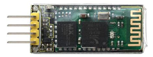
Specification Parameters:
- 1) Bluetooth Protocol: Bluetooth 2.1+ EDR Standard
- 2) USB Protocol: USB v1.1/2.0
- 3) Operating Frequency: 2.4GHz ISM Frequency Band
- 4) Modulation Mode: Gauss Frequency Shift Keying
- 5) Transmit Power: ≤ 4dBm, Second Stage
- 6) Sensitivity: ≤-84dBm at 0.1% Bit Error Rate
- 7) Transmission Speed: 2.1Mbps(Max)/160 kbps(Asynchronous);1Mbps/1Mbps(Synchronous)
-
Safety Feature: Authentication and Encryption
- 9) Supported Configuration: Bluetooth Serial Port (major and minor)
- 10) Supply Voltage: DC 5V
- 11) Operating Temperature: -20 to 55℃
2)Bluetooth Control Key Test
Description:
Next, we are going to introduce the use method for HC-06 Bluetooth module. To easily use the HC-06 Bluetooth module to control the robot arm, we particularly design the APP control. Shown below.
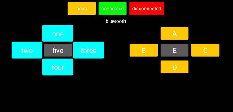
You can download the APP from the link:
https://drive.google.com/open?id=10U7EWyCyb5bGUxWm3DXRXGKEm1UQGU4Q
There are 10 control keys on the App. When connect well the HC-06 Bluetooth module to Android phone using our APP, press the control key, Android phone will receive a corresponding value.
When programming, you can set the function for the corresponding value. So in the experiment, we will test each key to get the corresponding value.
Pay special attention to:
1) First should pair Bluetooth in the phone settings. Connect the Bluetooth to shield, powered up, LED on the Bluetooth module flashes, then open the mobile Bluetooth, search for a Bluetooth device.
If find a new address, pair and enter 1234, paired successfully, you should see the address name change to HC-06.
2) Must first upload the test program successfully, then connect the Bluetooth, pair and connect the App. Otherwise, fail to upload the program.
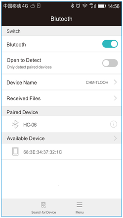
Hookup Guide:
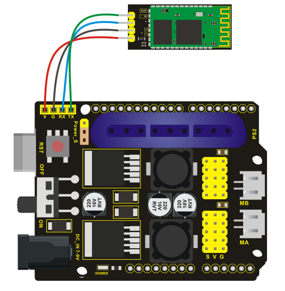
Test Code 8:
void setup()
{
Serial.begin(9600);     // set the serial baud rate to 9600
}
void loop()
{
char val;    // define a variable, used to receive the value read from Bluetooth.
if(Serial.available())     // if receive the value
{
val = Serial.read();       // assign the value read to val
Serial.println(val);
}
}
Test Result:
Upload the code, hookup well and power up. After connecting the Bluetooth APP, open the serial monitor and set the baud rate to 9600, press down the control key on the APP, you should see the corresponding value. Shown below.
| key | value |
|---|---|
| one | 1 |
| two | 2 |
| three | 3 |
| four | 4 |
| five | 5 |
| A | A |
| B | B |
| C | C |
| D | D |
| E | E |
3)Bluetooth Controlling Arm
Description:
In this experiment, we combine a Android APP and HC-06 Bluetooth module to control the robot arm.
The controlling method are shown below.
| key | Corresponding arm action |
|---|---|
| one | The lower arm stretches out |
| two | The clamp claw opens |
| three | The clamp claw is closed |
| four | The lower arm draws back |
| five | — |
| A | The upper arm lifts up |
| B | The arm turns left |
| C | The arm turns right |
| D | The upper arm goes down |
| E | — |
Hookup Guide:
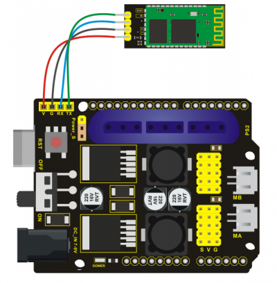
Test Code 9:
#include <Servo.h>  // add the servo libraries
Servo myservo1;  // create servo object to control a servo
Servo myservo2;
Servo myservo3;
Servo myservo4;
int pos1=80, pos2=60, pos3=130, pos4=0;  // define the variable of 4 servo angle and assign the initial value( that is the boot posture angle value)
char val;
void setup()
{
// boot posture
myservo1.write(pos1);
delay(1000);
myservo2.write(pos2);
myservo3.write(pos3);
myservo4.write(pos4);
delay(1500);
Serial.begin(9600); //  set the baud rate to 9600
}
void loop()
{
myservo1.attach(A1);  // set the control pin of servo 1 to A1
myservo2.attach(A0);  // set the control pin of servo 2 to A0
myservo3.attach(6);   // set the control pin of servo 3 to D6
myservo4.attach(9);   // set the control pin of servo 4 to D9
if(Serial.available())   // if receive the data
{
val=Serial.read();    // read the received data
Serial.println(val);
switch(val)
{
case 'B':  T_left();  break;   // execute the corresponding function when receive the value
case 'C':  T_right();  break;
case 'A':  RF();  break;
case 'D':  RB();  break;
case '2':  ZK();  break;
case '3':  ZB();  break;
case '1':  LF();  break;
case '4':  LB();  break;
}
}
}
//**************************************************
// turn left
void T_left()
{
pos1=pos1+1;
myservo1.write(pos1);
delay(5);
if(pos1>180)
{
pos1=180;
}
}
//turn right
void T_right()
{
pos1=pos1-1;
myservo1.write(pos1);
delay(5);
if(pos1<1)
{
pos1=1;
}
}
//********************************************
//open the claw
void ZK()
{
pos4=pos4-2;
Serial.println(pos4);
myservo4.write(pos4);
delay(5);
if(pos4<2)
{
pos4=0;
}
}
// close the claw
void ZB()
{
pos4=pos4+8;
Serial.println(pos4);
myservo4.write(pos4);
delay(5);
if(pos4>108)
{
pos4=108;
}
}
//******************************************
// the upper arm will lift up
void RF()
{
pos2=pos2-1;
myservo2.write(pos2);
delay(5);
if(pos2<0)
{
pos2=0;
}
}
// the upper arm will go down
void RB()
{
pos2=pos2+1;
myservo2.write(pos2);
delay(5);
if(pos2>180)
{
pos2=180;
}
}
//***************************************
// the lower arm will stretch out
void LB()
{
pos3=pos3+1;
myservo3.write(pos3);
delay(5);
if(pos3>180)
{
pos3=180;
}
}
// the lower arm will draw back
void LF()
{
pos3=pos3-1;
myservo3.write(pos3);
delay(5);
if(pos3<35)
{
pos3=35;
}
}
Test Result:
Upload the code, connect it up and power on, after connecting the Bluetooth APP, press the key to control the robot arm do commanded motions.
Project 5: PS2 Controlled Robot Arm (Extension)
1)PS2 Joypad Key Test
Description:
On the drive shield there is a PS2 Joystick connector, which is easy for you to control the 4DOF robot arm using the PS2 Joypad. But you need to purchase it by yourself because the PS2 Joypad is not included in the kit.
When use the PS2 Joypad to control the robot arm, first need to get the corresponding character of each key on the PS2 Joypad.
So this experiment will help you test the character of each key on the PS2 Joypad.
After connecting the Joypad, should upload the test program on Arduino IDE. But before testing, should place the PS2X_lib folder inside the libraries folder of Arduino IDE directory.
Uploading the code, open the serial monitor, connect the PS2 Joypad. When press down the key, you should see the corresponding character on the monitor.
Test Code 10:
#include <PS2X_lib.h>  //for v1.6
/******************************************************************
* set pins connected to PS2 controller:
*   - 1e column: original
*   - 2e colmun: Stef?
* replace pin numbers by the ones you use
******************************************************************/
#define PS2_DAT        13  //14
#define PS2_CMD        11  //15
#define PS2_SEL        10  //16
#define PS2_CLK        12  //17
/******************************************************************
* select modes of PS2 controller:
*   - pressures = analog reading of push-butttons
*   - rumble    = motor rumbling
* uncomment 1 of the lines for each mode selection
******************************************************************/
//#define pressures   true
#define pressures   false
//#define rumble      true
#define rumble      false
PS2X ps2x; // create PS2 Controller Class
//right now, the library does NOT support hot pluggable controllers, meaning
//you must always either restart your Arduino after you connect the controller,
//or call config_gamepad(pins) again after connecting the controller.
int error = 0;
byte type = 0;
byte vibrate = 0;
void setup(){
Serial.begin(57600);
delay(300);  //added delay to give wireless ps2 module some time to startup, before configuring it
//CHANGES for v1.6 HERE!!! **************PAY ATTENTION*************
//setup pins and settings: GamePad(clock, command, attention, data, Pressures?, Rumble?) check for error
error = ps2x.config_gamepad(PS2_CLK, PS2_CMD, PS2_SEL, PS2_DAT, pressures, rumble);
if(error == 0){
Serial.print("Found Controller, configured successful ");
Serial.print("pressures = ");
if (pressures)
Serial.println("true ");
else
Serial.println("false");
Serial.print("rumble = ");
if (rumble)
Serial.println("true)");
else
Serial.println("false");
Serial.println("Try out all the buttons, X will vibrate the controller, faster as you press harder;");
Serial.println("holding L1 or R1 will print out the analog stick values.");
Serial.println("Note: Go to www.billporter.info for updates and to report bugs.");
}
else if(error == 1)
Serial.println("No controller found, check wiring, see readme.txt to enable debug. visit www.billporter.info for troubleshooting tips");
else if(error == 2)
Serial.println("Controller found but not accepting commands. see readme.txt to enable debug. Visit www.billporter.info for troubleshooting tips");
else if(error == 3)
Serial.println("Controller refusing to enter Pressures mode, may not support it. ");
//  Serial.print(ps2x.Analog(1), HEX);
type = ps2x.readType();
switch(type) {
case 0:
Serial.print("Unknown Controller type found ");
break;
case 1:
Serial.print("DualShock Controller found ");
break;
case 2:
Serial.print("GuitarHero Controller found ");
break;
case 3:
Serial.print("Wireless Sony DualShock Controller found ");
break;
}
}
void loop() {
/* You must Read Gamepad to get new values and set vibration values
ps2x.read_gamepad(small motor on/off, larger motor strenght from 0-255)
if you don't enable the rumble, use ps2x.read_gamepad(); with no values
You should call this at least once a second
*/
if(error == 1) //skip loop if no controller found
return;
if(type == 2){ //Guitar Hero Controller
ps2x.read_gamepad();          //read controller
if(ps2x.ButtonPressed(GREEN_FRET))
Serial.println("Green Fret Pressed");
if(ps2x.ButtonPressed(RED_FRET))
Serial.println("Red Fret Pressed");
if(ps2x.ButtonPressed(YELLOW_FRET))
Serial.println("Yellow Fret Pressed");
if(ps2x.ButtonPressed(BLUE_FRET))
Serial.println("Blue Fret Pressed");
if(ps2x.ButtonPressed(ORANGE_FRET))
Serial.println("Orange Fret Pressed");
if(ps2x.ButtonPressed(STAR_POWER))
Serial.println("Star Power Command");
if(ps2x.Button(UP_STRUM))          //will be TRUE as long as button is pressed
Serial.println("Up Strum");
if(ps2x.Button(DOWN_STRUM))
Serial.println("DOWN Strum");
if(ps2x.Button(PSB_START))         //will be TRUE as long as button is pressed
Serial.println("Start is being held");
if(ps2x.Button(PSB_SELECT))
Serial.println("Select is being held");
if(ps2x.Button(ORANGE_FRET)) {     // print stick value IF TRUE
Serial.print("Wammy Bar Position:");
Serial.println(ps2x.Analog(WHAMMY_BAR), DEC);
}
}
else { //DualShock Controller
ps2x.read_gamepad(false, vibrate); //read controller and set large motor to spin at 'vibrate' speed
if(ps2x.Button(PSB_START))         //will be TRUE as long as button is pressed
Serial.println("Start is being held");
if(ps2x.Button(PSB_SELECT))
Serial.println("Select is being held");
if(ps2x.Button(PSB_PAD_UP)) {      //will be TRUE as long as button is pressed
Serial.print("Up held this hard: ");
Serial.println(ps2x.Analog(PSAB_PAD_UP), DEC);
}
if(ps2x.Button(PSB_PAD_RIGHT)){
Serial.print("Right held this hard: ");
Serial.println(ps2x.Analog(PSAB_PAD_RIGHT), DEC);
}
if(ps2x.Button(PSB_PAD_LEFT)){
Serial.print("LEFT held this hard: ");
Serial.println(ps2x.Analog(PSAB_PAD_LEFT), DEC);
}
if(ps2x.Button(PSB_PAD_DOWN)){
Serial.print("DOWN held this hard: ");
Serial.println(ps2x.Analog(PSAB_PAD_DOWN), DEC);
}
vibrate = ps2x.Analog(PSAB_CROSS);  //this will set the large motor vibrate speed based on how hard you press the blue (X) button
if (ps2x.NewButtonState()) {        //will be TRUE if any button changes state (on to off, or off to on)
if(ps2x.Button(PSB_L3))
Serial.println("L3 pressed");
if(ps2x.Button(PSB_R3))
Serial.println("R3 pressed");
if(ps2x.Button(PSB_L2))
Serial.println("L2 pressed");
if(ps2x.Button(PSB_R2))
Serial.println("R2 pressed");
if(ps2x.Button(PSB_TRIANGLE))
Serial.println("Triangle pressed");
}
if(ps2x.ButtonPressed(PSB_CIRCLE))               //will be TRUE if button was JUST pressed
Serial.println("Circle just pressed");
if(ps2x.NewButtonState(PSB_CROSS))               //will be TRUE if button was JUST pressed OR released
Serial.println("X just changed");
if(ps2x.ButtonReleased(PSB_SQUARE))              //will be TRUE if button was JUST released
Serial.println("Square just released");
if(ps2x.Button(PSB_L1) || ps2x.Button(PSB_R1)) { //print stick values if either is TRUE
Serial.print("Stick Values:");
Serial.print(ps2x.Analog(PSS_LY), DEC); //Left stick, Y axis. Other options: LX, RY, RX
Serial.print(",");
Serial.print(ps2x.Analog(PSS_LX), DEC);
Serial.print(",");
Serial.print(ps2x.Analog(PSS_RY), DEC);
Serial.print(",");
Serial.println(ps2x.Analog(PSS_RX), DEC);
}
}
delay(50);
}
Test Result:
Stack the drive shield onto REV4 board and upload the code. Connecting the PS2 Joypad, open the serial monitor and set the baud rate to 57600. When press down the key or push the rocker, you should see the corresponding character showed on the monitor.
2)PS2 Joypad Control
Description:
In the previous section, we have showed how to use Joystick module to control the robot arm. It is almost the same for you to control the 4DOF robot arm using the PS2 Joypad.
Hookup Guide:
Test Code 11:
#include <PS2X_lib.h>
PS2X ps2x; // create PS2 Controller Class
//right now, the library does NOT support hot pluggable controllers, meaning
//you must always either restart your Arduino after you connect the controller,
//or call config_gamepad(pins) again after connecting the controller.
int error = 0;
byte vibrate = 0;
#include <Servo.h>  // add the servo libraries
Servo myservo1;  // create servo object to control a servo
Servo myservo2;
Servo myservo3;
Servo myservo4;
int pos1=80, pos2=60, pos3=130, pos4=0;  // define the variable of 4 servo angle and assign the initial value( that is the boot posture angle value)
void setup(){
Serial.begin(57600);
// boot posture
myservo1.write(pos1);
delay(1000);
myservo2.write(pos2);
myservo3.write(pos3);
myservo4.write(pos4);
delay(1500);
error = ps2x.config_gamepad(13,11,10,12);   //setup GamePad(clock, command, attention, data) pins, check for error
if(error == 0){
Serial.println("Found Controller, configured successful");
Serial.println("Try out all the buttons, X will vibrate the controller, faster as you press harder;");
Serial.println("holding L1 or R1 will print out the analog stick values.");
Serial.println("Go to www.billporter.info for updates and to report bugs.");
}
else if(error == 1)
Serial.println("No controller found, check wiring, see readme.txt to enable debug. visit www.billporter.info for troubleshooting tips");
else if(error == 2)
Serial.println("Controller found but not accepting commands. see readme.txt to enable debug. Visit www.billporter.info for troubleshooting tips");
//Serial.print(ps2x.Analog(1), HEX);
ps2x.enableRumble();              //enable rumble vibration motors
ps2x.enablePressures();           //enable reading the pressure values from the buttons.
}
void loop(){
/* You must Read Gamepad to get new values
Read GamePad and set vibration values
ps2x.read_gamepad(small motor on/off, larger motor strenght from 0-255)
if you don't enable the rumble, use ps2x.read_gamepad(); with no values
you should call this at least once a second
*/
myservo1.attach(A1);  // set the control pin of servo 1 to A1
myservo2.attach(A0);  // set the control pin of servo 2 to A0
myservo3.attach(6);   // set the control pin of servo 3 to D6
myservo4.attach(9);   // set the control pin of servo 4 to D9
if(error != 0)
return;
ps2x.read_gamepad(false, vibrate);          //read controller and set large motor to spin at 'vibrate' speed
if(ps2x.Button(PSB_START))                   //will be TRUE as long as button is pressed
Serial.println("Start is being held");
if(ps2x.Button(PSB_SELECT))
Serial.println("Select is being held");
if(ps2x.Button(PSB_PAD_UP)) {         //will be TRUE as long as button is pressed
Serial.print("Up held this hard: ");
Serial.println(ps2x.Analog(PSAB_PAD_UP), DEC);
}
if(ps2x.Button(PSB_PAD_RIGHT)){
Serial.print("Right held this hard: ");
Serial.println(ps2x.Analog(PSAB_PAD_RIGHT), DEC);
}
if(ps2x.Button(PSB_PAD_LEFT)){
Serial.print("LEFT held this hard: ");
Serial.println(ps2x.Analog(PSAB_PAD_LEFT), DEC);
}
if(ps2x.Button(PSB_PAD_DOWN)){
Serial.print("DOWN held this hard: ");
Serial.println(ps2x.Analog(PSAB_PAD_DOWN), DEC);
}
vibrate = ps2x.Analog(PSAB_BLUE);        //this will set the large motor vibrate speed based on
//how hard you press the blue (X) button
if (ps2x.NewButtonState())               //will be TRUE if any button changes state (on to off, or off to on)
{
if(ps2x.Button(PSB_R3))
Serial.println("R3 pressed");
if(ps2x.Button(PSB_L3))
Serial.println("L3 pressed");
if(ps2x.Button(PSB_L2))
Serial.println("L2 pressed");
if(ps2x.Button(PSB_R2))
Serial.println("R2 pressed");
if(ps2x.Button(PSB_GREEN))
Serial.println("Triangle pressed");
}
if(ps2x.ButtonPressed(PSB_RED))             //will be TRUE if button was JUST pressed
Serial.println("Circle just pressed");
if(ps2x.ButtonReleased(PSB_PINK))             //will be TRUE if button was JUST released
Serial.println("Square just released");
if(ps2x.NewButtonState(PSB_BLUE))            //will be TRUE if button was JUST pressed OR released
Serial.println("X just changed");
//转动
zhuandong();
//爪子
zhuazi();
//大臂
dabi();
//小臂
xiaobi();
if(ps2x.Button(PSB_L1) || ps2x.Button(PSB_R1)) // print stick values if either is TRUE
{
Serial.print("Stick Values:");
Serial.print(ps2x.Analog(PSS_LY), DEC); //Left stick, Y axis. Other options: LX, RY, RX
Serial.print(",");
Serial.print(ps2x.Analog(PSS_LX), DEC);
Serial.print(",");
Serial.print(ps2x.Analog(PSS_RY), DEC);
Serial.print(",");
Serial.println(ps2x.Analog(PSS_RX), DEC);
}
delay(5);
}
//********************************************************************
// turn
void zhuandong()
{
//turn right
if(ps2x.Analog (PSS_RX) > 200)  // if push the right joystick to the right
{
//Serial.println(ps2x.Analog(PSS_RX), DEC);
pos1=pos1-1;    //pos1 subtracts 1
myservo1.write(pos1);   // servo 1 executes the action, the arm will turn right.
// delay(5);
if(pos1<1)   // limit the right turning angle
{
pos1=1;
}
}
// turn left
if(ps2x.Analog (PSS_RX) < 50)    // if push the right joystick to the left
{
//Serial.println(ps2x.Analog(PSS_RX), DEC);
pos1=pos1+1;   //pos1 plus 1
myservo1.write(pos1);     // the arm turns left
// delay(5);
if(pos1>180)     // limit the left turning angle
{
pos1=180;
}
}
}
//**********************************************************************
// upper arm
void xiaobi()
{
//upper arm front
if(ps2x.Analog(PSS_RY)<50)  // if push the right joystick upward
{
pos2=pos2-1;
myservo2.write(pos2);    // the upper arm will lift
delay(5);
if(pos2<0)    // limit the lifting angle
{
pos2=0;
}
}
//upper arm back
if(ps2x.Analog(PSS_RY)>200)    // if push the right joystick downward
{
pos2=pos2+1;
myservo2.write(pos2);   // the upper arm will go down
delay(5);
if(pos2>180)  // limit the declining angle
{
pos2=180;
}
}
}
//***************************************************************
void zhuazi()
{
// close the claw
if(ps2x.Analog(PSS_LX)>220)   // if push the left joystick to the right
{
pos4=pos4-1;
Serial.println(pos4);
myservo4.write(pos4);  // servo 4 carries out the action and the claw is gradually closed.
delay(5);
if(pos4<0)   // if pos4 value subtracts to 37, the claw in 37 degrees we have tested is closed.)
{
pos4=0;
}
}
// open the claw
if(ps2x.Analog(PSS_LX)<10)   // if push the left joystick to the left
{
pos4=pos4+8;
Serial.println(pos4);
myservo4.write(pos4);   // servo 4 carries out the action and the claw is gradually opened
delay(5);
if(pos4>108)    // limit the maximum opening angle
{
pos4=108;
}
}
}
//*********************************************************
void dabi()
{
// lower arm front
if(ps2x.Analog(PSS_LY)>200)  // if push the left joystick upward
{
pos3=pos3+1;
myservo3.write(pos3);  // the lower arm will stretch out
delay(5);
if(pos3>180)   // limit the stretched angle
{
pos3=180;
}
}
if(ps2x.Analog(PSS_LY)<10)    //if push the left joystick downward
{
pos3=pos3-1;
myservo3.write(pos3);   // the lower arm will draw back
delay(5);
if(pos3<35)    // limit the retracted angle
{
pos3=35;
}
}
}
Test Result:
Stack the shield onto REV4 board and upload the code. Powered on and connected the PS2 Joypad, you can use the PS2 Joypad to control the robot arm actions.
3)PS2 Controlling Posture Memory
Description:
In the previous experiment, we have showed how to use Joystick module to control the robot arm memorize several postures. Now we replace the joystick module with PS2 Joypad. The program thought is almost the same.
Hookup Guide:
Test Code 12:
#include <PS2X_lib.h>
#include <Servo.h>  // add the servo libraries
Servo myservo1;  // create servo object to control a servo
Servo myservo2;
Servo myservo3;
Servo myservo4;
int pos1=80, pos2=60, pos3=130, pos4=0;  // define the variable of 4 servo angle and assign the initial value( that is the boot posture angle value)
PS2X ps2x; // create PS2 Controller Class
//right now, the library does NOT support hot pluggable controllers, meaning
//you must always either restart your Arduino after you conect the controller,
//or call config_gamepad(pins) again after connecting the controller.
int error = 0;
byte vibrate = 0;
int s1,s2,s3,s4;
int jiyi1[20];  // define four array, separately used to save the angle of 4 servos.
int jiyi2[20];
int jiyi3[20];
int jiyi4[20];
int i=0;
int j=0;
void setup()
{
Serial.begin(57600);
// boot posture
myservo1.write(pos1);
delay(1000);
myservo2.write(pos2);
myservo3.write(pos3);
myservo4.write(pos4);
delay(1500);
error = ps2x.config_gamepad(13,11,10,12);   //setup GamePad(clock, command, attention, data) pins, check for error
if(error == 0){
Serial.println("Found Controller, configured successful");
Serial.println("Try out all the buttons, X will vibrate the controller, faster as you press harder;");
Serial.println("holding L1 or R1 will print out the analog stick values.");
Serial.println("Go to www.billporter.info for updates and to report bugs.");
}
else if(error == 1)
Serial.println("No controller found, check wiring, see readme.txt to enable debug. visit www.billporter.info for troubleshooting tips");
else if(error == 2)
Serial.println("Controller found but not accepting commands. see readme.txt to enable debug. Visit www.billporter.info for troubleshooting tips");
//Serial.print(ps2x.Analog(1), HEX);
ps2x.enableRumble();              //enable rumble vibration motors
ps2x.enablePressures();           //enable reading the pressure values from the buttons.
}
void loop()
{
myservo1.attach(A1);  // set the control pin of servo 1 to A1
myservo2.attach(A0);  // set the control pin of servo 2 to A0
myservo3.attach(6);   // set the control pin of servo 3 to D6
myservo4.attach(9);   // set the control pin of servo 4 to D9
if(error != 0)
return;
ps2x.read_gamepad(false, vibrate);          //read controller and set large motor to spin at 'vibrate' speed
if(ps2x.Button(PSB_START))                   //will be TRUE as long as button is pressed
Serial.println("Start is being held");
if(ps2x.Button(PSB_SELECT))
Serial.println("Select is being held");
if(ps2x.Button(PSB_PAD_UP)) {         //will be TRUE as long as button is pressed
Serial.print("Up held this hard: ");
Serial.println(ps2x.Analog(PSAB_PAD_UP), DEC);
}
if(ps2x.Button(PSB_PAD_RIGHT)){
Serial.print("Right held this hard: ");
Serial.println(ps2x.Analog(PSAB_PAD_RIGHT), DEC);
}
if(ps2x.Button(PSB_PAD_LEFT)){
Serial.print("LEFT held this hard: ");
Serial.println(ps2x.Analog(PSAB_PAD_LEFT), DEC);
}
if(ps2x.Button(PSB_PAD_DOWN)){
Serial.print("DOWN held this hard: ");
Serial.println(ps2x.Analog(PSAB_PAD_DOWN), DEC);
}
vibrate = ps2x.Analog(PSAB_BLUE);        //this will set the large motor vibrate speed based on
//how hard you press the blue (X) button
if (ps2x.NewButtonState())               //will be TRUE if any button changes state (on to off, or off to on)
{
if(ps2x.Button(PSB_R3))
{
//Serial.println("R3 pressed");
// record
s1=myservo1.read();
delay(100);
Serial.println(s1);
s2=myservo2.read();
delay(100);
Serial.println(s2);
s3=myservo3.read();
delay(100);
Serial.println(s3);
s4=myservo4.read();
delay(100);
Serial.println(s4);
jiyi1[i]=s1;  // save the servo value read in the array sequentially
jiyi2[i]=s2;
jiyi3[i]=s3;
jiyi4[i]=s4;
i++;
j=i;
// delay(100);
Serial.println(i);
}
if(ps2x.Button(PSB_L3))
{
//Serial.println("L3 pressed");
i=0;
//执行
pos1 = myservo1.read();
pos2 = myservo2.read();
pos3 = myservo3.read();
pos4 = myservo4.read();
for(int k=0;k<j;k++)  //for loop, to execute all the stored actions
{
if(pos1<jiyi1[k])  //if the current servo 1 angle is less than the value stored in array 1.
{
while(pos1<jiyi1[k])  //while loop, make servo turn to the position of value stored in the array.
{
myservo1.write(pos1);   // servo 1 executes the action
delay(5);   // delay 5ms,controlling the rotating speed of servo
pos1++;
//Serial.println(pos1);
}
}
else   //if the current servo 1 angle is greater than the value stored in array 1.
{
while(pos1>jiyi1[k])  //while loop, make servo turn to the position of value stored in the array.
{
myservo1.write(pos1);   // servo 1 executes the action
delay(5);    //delay 5ms,controlling the rotating speed of servo
pos1--;
//Serial.println(pos1);
}
//**********************************************
// the same analysis as the previous servo
if(pos2<jiyi2[k])
{
while(pos2<jiyi2[k])
{
myservo2.write(pos2);
delay(5);
pos2++;
//Serial.println(pos1);
}
}
else
{
while(pos2>jiyi2[k])
{
myservo2.write(pos2);
delay(5);
pos2--;
//Serial.println(pos1);
}
}
//*****************************************************
//the same analysis
if(pos3<jiyi3[k])
{
while(pos3<jiyi3[k])
{
myservo3.write(pos3);
delay(5);
pos3++;
//Serial.println(pos1);
}
}
else
{
while(pos3>jiyi3[k])
{
myservo3.write(pos3);
delay(5);
pos3--;
//Serial.println(pos1);
}
}
//*****************************************************
//the same analysis
if(pos4<jiyi4[k])
{
while(pos4<jiyi4[k])
{
myservo4.write(pos4);
delay(5);
pos4++;
//Serial.println(pos1);
}
}
else
{
while(pos4>jiyi4[k])
{
myservo4.write(pos4);
delay(5);
pos4--;
//Serial.println(pos1);
}
}
}
}
}
if(ps2x.Button(PSB_L2))
Serial.println("L2 pressed");
if(ps2x.Button(PSB_R2))
Serial.println("R2 pressed");
if(ps2x.Button(PSB_GREEN))
Serial.println("Triangle pressed");
}
if(ps2x.ButtonPressed(PSB_RED))             //will be TRUE if button was JUST pressed
Serial.println("Circle just pressed");
if(ps2x.ButtonReleased(PSB_PINK))             //will be TRUE if button was JUST released
Serial.println("Square just released");
if(ps2x.NewButtonState(PSB_BLUE))            //will be TRUE if button was JUST pressed OR released
Serial.println("X just changed");
// turn
zhuandong();
// claw
zhuazi();
// lower arm
dabi();
// upper arm
xiaobi();
if(ps2x.Button(PSB_L1) || ps2x.Button(PSB_R1)) // print stick values if either is TRUE
{
Serial.print("Stick Values:");
Serial.print(ps2x.Analog(PSS_LY), DEC); //Left stick, Y axis. Other options: LX, RY, RX
Serial.print(",");
Serial.print(ps2x.Analog(PSS_LX), DEC);
Serial.print(",");
Serial.print(ps2x.Analog(PSS_RY), DEC);
Serial.print(",");
Serial.println(ps2x.Analog(PSS_RX), DEC);
}
delay(5);
}
//********************************************************************
// turn
void zhuandong()
{
//turn right
if(ps2x.Analog (PSS_RX) > 200)  // if push the right joystick to the right
{
//Serial.println(ps2x.Analog(PSS_RX), DEC);
pos1=pos1-1;    //pos1 subtracts 1
myservo1.write(pos1);   // servo 1 carries out the action and the arm will turn right
// delay(5);
if(pos1<1)   // limit the right turning angle
{
pos1=1;
}
}
//左转
if(ps2x.Analog (PSS_RX) < 50)    //if push the right joystick to the left
{
//Serial.println(ps2x.Analog(PSS_RX), DEC);
pos1=pos1+1;   //pos1 plus 1
myservo1.write(pos1);     // the arm will turn left
// delay(5);
if(pos1>180)     // limit the left turning angle
{
pos1=180;
}
}
}
//**********************************************************************
// upper arm
void xiaobi()
{
//upper arm front
if(ps2x.Analog(PSS_RY)<50)  // if push the right joystick upward
{
pos2=pos2-1;
myservo2.write(pos2);    // the upper arm will lift up
delay(5);
if(pos2<0)    // limit the lifting angle
{
pos2=0;
}
}
// upper arm back
if(ps2x.Analog(PSS_RY)>200)    //if push the right joystick downward
{
pos2=pos2+1;
myservo2.write(pos2);   // the upper arm will go down
delay(5);
if(pos2>180)  // limit the declining angle
{
pos2=180;
}
}
}
//***************************************************************
void zhuazi()
{
// close the claw
if(ps2x.Analog(PSS_LX)>220)   // if push the left joystick to the right
{
pos4=pos4-1;
Serial.println(pos4);
myservo4.write(pos4);  // servo 4 carries out the action and the claw is gradually closed.
delay(5);
if(pos4<0)   // if pos4 value reduces to 37(the claw we test in 37degrees is closed)
{
pos4=0;
}
}
// open the claw
if(ps2x.Analog(PSS_LX)<10)   // if push the left joystick to the left
{
pos4=pos4+8;
Serial.println(pos4);
myservo4.write(pos4);   // servo 4 carries out the action and the claw is gradually opened
delay(5);
if(pos4>108)    // limit the maximum angle opened
{
pos4=108;
}
}
}
//*********************************************************
void dabi()
{
// lower arm front
if(ps2x.Analog(PSS_LY)>200)  //  if push the left joystick upward
{
pos3=pos3+1;
myservo3.write(pos3);  // the lower arm will stretch out
delay(5);
if(pos3>180)   // limit the stretched angle
{
pos3=180;
}
}
if(ps2x.Analog(PSS_LY)<10)    // if push the left joystick downward
{
pos3=pos3-1;
myservo3.write(pos3);   //the lower arm will retract
delay(5);
if(pos3<35)    // limit the retracted angle
{
pos3=35;
}
}
}
Test Result:
Stack the shield onto REV4 board and upload the code. Powered on and connected the PS2 Joypad, you can use the PS2 Joypad to control the robot arm memorize several postures.
4)PS2 Controlling Posture Memory And Loop
Description:
In the previous experiment, we have showed how to use Joystick module to control the robot arm memorize several postures and loop. Now we replace the Joystick module with the PS2 Joypad. The program is almost the same.
Hookup Guide:
Test Code 13:
#include <PS2X_lib.h>
#include <Servo.h>  // add the servo libraries
Servo myservo1;  // create servo object to control a servo
Servo myservo2;
Servo myservo3;
Servo myservo4;
int pos1=80, pos2=60, pos3=130, pos4=0;  // define the variable of 4 servo angle and assign the initial value( that is the boot posture angle value)
PS2X ps2x; // create PS2 Controller Class
//right now, the library does NOT support hot pluggable controllers, meaning
//you must always either restart your Arduino after you conect the controller,
//or call config_gamepad(pins) again after connecting the controller.
int error = 0;
byte vibrate = 0;
int s1,s2,s3,s4;
int jiyi1[30];   //define four array, separately used to save the angle of 4 servos.
int jiyi2[30];
int jiyi3[30];
int jiyi4[30];
int i=0;
int j=0,tt=0;
void setup()
{
Serial.begin(57600);
// boot posture
myservo1.write(pos1);
delay(1000);
myservo2.write(pos2);
myservo3.write(pos3);
myservo4.write(pos4);
delay(1500);
error = ps2x.config_gamepad(13,11,10,12);   //setup GamePad(clock, command, attention, data) pins, check for error
if(error == 0){
Serial.println("Found Controller, configured successful");
Serial.println("Try out all the buttons, X will vibrate the controller, faster as you press harder;");
Serial.println("holding L1 or R1 will print out the analog stick values.");
Serial.println("Go to www.billporter.info for updates and to report bugs.");
}
else if(error == 1)
Serial.println("No controller found, check wiring, see readme.txt to enable debug. visit www.billporter.info for troubleshooting tips");
else if(error == 2)
Serial.println("Controller found but not accepting commands. see readme.txt to enable debug. Visit www.billporter.info for troubleshooting tips");
//Serial.print(ps2x.Analog(1), HEX);
ps2x.enableRumble();              //enable rumble vibration motors
ps2x.enablePressures();           //enable reading the pressure values from the buttons.
}
void loop()
{
myservo1.attach(A1);  // set the control pin of servo 1 to A1
myservo2.attach(A0);  //set the control pin of servo 2 to A0
myservo3.attach(6);   //set the control pin of servo 3 to D6
myservo4.attach(9);   //set the control pin of servo 4 to D9
if(error != 0)
return;
ps2x.read_gamepad(false, vibrate);          //read controller and set large motor to spin at 'vibrate' speed
if(ps2x.Button(PSB_START))                   //will be TRUE as long as button is pressed
Serial.println("Start is being held");
if(ps2x.Button(PSB_SELECT))
Serial.println("Select is being held");
if(ps2x.Button(PSB_PAD_UP)) {         //will be TRUE as long as button is pressed
Serial.print("Up held this hard: ");
Serial.println(ps2x.Analog(PSAB_PAD_UP), DEC);
}
if(ps2x.Button(PSB_PAD_RIGHT)){
Serial.print("Right held this hard: ");
Serial.println(ps2x.Analog(PSAB_PAD_RIGHT), DEC);
}
if(ps2x.Button(PSB_PAD_LEFT)){
Serial.print("LEFT held this hard: ");
Serial.println(ps2x.Analog(PSAB_PAD_LEFT), DEC);
}
if(ps2x.Button(PSB_PAD_DOWN)){
Serial.print("DOWN held this hard: ");
Serial.println(ps2x.Analog(PSAB_PAD_DOWN), DEC);
}
vibrate = ps2x.Analog(PSAB_BLUE);        //this will set the large motor vibrate speed based on
//how hard you press the blue (X) button
if (ps2x.NewButtonState())               //will be TRUE if any button changes state (on to off, or off to on)
{
if(ps2x.Button(PSB_R3))
{
//Serial.println("R3 pressed");
//record
s1=myservo1.read();
delay(100);
Serial.println(s1);
s2=myservo2.read();
delay(100);
Serial.println(s2);
s3=myservo3.read();
delay(100);
Serial.println(s3);
s4=myservo4.read();
delay(100);
Serial.println(s4);
jiyi1[i]=s1;  //save the servo value read in the array sequentially
jiyi2[i]=s2;
jiyi3[i]=s3;
jiyi4[i]=s4;
i++;
j=i;
// delay(100);
Serial.println(i);
}
// carry out
if(ps2x.Button(PSB_L3))
{
//Serial.println("L3 pressed");
i=0;
tt=1;
pos1 = myservo1.read();  // record the angle value of 4 servo posture
pos2 = myservo2.read();
pos3 = myservo3.read();
pos4 = myservo4.read();
while(tt==1)  // repeat the actions
{
for(int k=0;k<j;k++)   //for loop, to execute all the stored actions.
{
if(pos1<jiyi1[k])   // if the current servo 1 angle is less than the value stored in array 1.
{
while(pos1<jiyi1[k])    //while loop, make servo turn to the position of value stored in the array.
{
myservo1.write(pos1);   //servo 1 executes the action
delay(5);     //delay 5ms,controlling the rotating speed of servo.
pos1++;
//Serial.println(pos1);
}
}
else     //if the current servo 1 angle is greater than the value stored in array 1.
{
while(pos1>jiyi1[k])     //while loop, make servo turn to the position of value stored in the array.
{
myservo1.write(pos1);    //servo 1 executes the action
delay(5);           //delay 5ms,controlling the rotating speed of servo.
pos1--;
//Serial.println(pos1);
}
//**********************************************
// the same analysis as the previous servo
if(pos2<jiyi2[k])
{
while(pos2<jiyi2[k])
{
myservo2.write(pos2);
delay(5);
pos2++;
//Serial.println(pos1);
}
}
else
{
while(pos2>jiyi2[k])
{
myservo2.write(pos2);
delay(5);
pos2--;
//Serial.println(pos1);
}
}
//*****************************************************
// the same analysis as the previous servo
if(pos3<jiyi3[k])
{
while(pos3<jiyi3[k])
{
myservo3.write(pos3);
delay(5);
pos3++;
//Serial.println(pos1);
}
}
else
{
while(pos3>jiyi3[k])
{
myservo3.write(pos3);
delay(5);
pos3--;
//Serial.println(pos1);
}
}
//*****************************************************
// the same analysis as the previous servo
if(pos4<jiyi4[k])
{
while(pos4<jiyi4[k])
{
myservo4.write(pos4);
delay(5);
pos4++;
//Serial.println(pos1);
}
}
else
{
while(pos4>jiyi4[k])
{
myservo4.write(pos4);
delay(5);
pos4--;
//Serial.println(pos1);
}
}
}
}
//*******************************************************
// exit the looping
ps2x.enableRumble();              //enable rumble vibration motors
ps2x.enablePressures();
ps2x.read_gamepad(false, vibrate);
vibrate = ps2x.Analog(PSAB_BLUE);
if (ps2x.NewButtonState())               //will be TRUE if any button changes state (on to off, or off to on)
{
if(ps2x.Button(PSB_R3))
{
tt=0;
i=0;
break;
}
}
//*********************************************************
}
}
if(ps2x.Button(PSB_L2))
Serial.println("L2 pressed");
if(ps2x.Button(PSB_R2))
Serial.println("R2 pressed");
if(ps2x.Button(PSB_GREEN))
Serial.println("Triangle pressed");
}
if(ps2x.ButtonPressed(PSB_RED))             //will be TRUE if button was JUST pressed
Serial.println("Circle just pressed");
if(ps2x.ButtonReleased(PSB_PINK))             //will be TRUE if button was JUST released
Serial.println("Square just released");
if(ps2x.NewButtonState(PSB_BLUE))            //will be TRUE if button was JUST pressed OR released
Serial.println("X just changed");
//turn
zhuandong();
//claw
zhuazi();
//lower arm
dabi();
//upper arm
xiaobi();
if(ps2x.Button(PSB_L1) || ps2x.Button(PSB_R1)) // print stick values if either is TRUE
{
Serial.print("Stick Values:");
Serial.print(ps2x.Analog(PSS_LY), DEC); //Left stick, Y axis. Other options: LX, RY, RX
Serial.print(",");
Serial.print(ps2x.Analog(PSS_LX), DEC);
Serial.print(",");
Serial.print(ps2x.Analog(PSS_RY), DEC);
Serial.print(",");
Serial.println(ps2x.Analog(PSS_RX), DEC);
}
delay(5);
}
//********************************************************************
// turn
void zhuandong()
{
// turn right
if(ps2x.Analog (PSS_RX) > 200)  // if push the right joystick to the right
{
//Serial.println(ps2x.Analog(PSS_RX), DEC);
pos1=pos1-1;    //pos1 subtracts 1
myservo1.write(pos1);   // servo 1 carries out the action, the robot arm turns right.
// delay(5);
if(pos1<1)   // limit the right turning angle
{
pos1=1;
}
}
// turn left
if(ps2x.Analog (PSS_RX) < 50)    // if push the right joystick to the left
{
//Serial.println(ps2x.Analog(PSS_RX), DEC);
pos1=pos1+1;   //pos1 plus 1
myservo1.write(pos1);     // the robot arm turns left
// delay(5);
if(pos1>180)     // limit the left turning angle
{
pos1=180;
}
}
}
//**********************************************************************
// the upper arm
void xiaobi()
{
// upper arm front
if(ps2x.Analog(PSS_RY)<50)  // if push the right joystick upward
{
pos2=pos2-1;
myservo2.write(pos2);    // the upper arm will lift up
delay(5);
if(pos2<0)    // limit the lifting angle
{
pos2=0;
}
}
// upper arm back
if(ps2x.Analog(PSS_RY)>200)    //if push the right joystick to downward
{
pos2=pos2+1;
myservo2.write(pos2);   // the robot arm will go down
delay(5);
if(pos2>180)  // limit the declining angle
{
pos2=180;
}
}
}
//***************************************************************
void zhuazi()
{
// close the claw
if(ps2x.Analog(PSS_LX)>220)   // if push the left joystick to the right
{
pos4=pos4-1;
Serial.println(pos4);
myservo4.write(pos4);  // servo 4 carries out the action and claw is gradually closed
delay(5);
if(pos4<0)   // if pos4 value subtracts to 37, the claw in 37 degrees we have tested is closed.)
{
pos4=0;
}
}
// open the claw
if(ps2x.Analog(PSS_LX)<10)   //  if push the left joystick to the left
{
pos4=pos4+8;
Serial.println(pos4);
myservo4.write(pos4);   //  servo 4 carries out the action and claw is gradually opened
delay(5);
if(pos4>108)    // limit the maximum angle opened
{
pos4=108;
}
}
}
//*********************************************************
void dabi()
{
// lower arm front
if(ps2x.Analog(PSS_LY)>200)  // if push the left joystick upward
{
pos3=pos3+1;
myservo3.write(pos3);  //  the lower arm will stretch out
delay(5);
if(pos3>180)   // limit the stretched angle
{
pos3=180;
}
}
if(ps2x.Analog(PSS_LY)<10)    // if push the left joystick downward
{
pos3=pos3-1;
myservo3.write(pos3);   // the lower arm will draw back
delay(5);
if(pos3<35)    //  limit the retracted angle
{
pos3=35;
}
}
}
Test Result:
Stack the shield onto REV4 board and upload the code. Powered on and connected the PS2 Joypad, you can use the PS2 Joypad to control the robot arm memorize several postures, looping.
More Resources
Download libraries, software, app and test code:
https://fs.keyestudio.com/KS0198
ARDUINO Software: https://www.arduino.cc/en/Main/OldSoftwareReleases#1.5.x
Our Tutorial
This tutorial is designed for everyone to DIY robot arm. You will learn all the basic information about how to control this robot arm with Joystick and Bluetooth. Just enjoy your time!
Great! It’s just the beginning of ARDUINO programming journey. There are more and more awesome projects for you to explore. Furthermore, our KEYESTUDIO research and development team will continue to explore on this path, walking you through the basics up to complex projects. Hope that you can enjoy our works!
About keyestudio
Located in Shenzhen, the Silicon Valley of China, KEYES DIY ROBOT CO.,LTD is a thriving technology company dedicated to open-source hardware research and development, production and marketing. Keyestudio is a best-selling brand owned by KEYES Corporation, our product lines range from Arduino boards, shields, sensor modules, Raspberry Pi, micro:bit extension boards and smart car to complete starter kits designed for customers of any level to learn Arduino knowledge.
All of our products comply with international quality standards and are greatly appreciated in a variety of different markets throughout the world. For more details of our products, you can check it from the links below.
Official Website: http://www.keyestudio.com/
Customer Service
As a continuous and fast growing technology company, we keep striving our best to offer you excellent products and quality service as to meet your expectation. We look forward to hearing from you and any of your critical
comment or suggestion would be much valuable to us.
You can reach out to us by simply drop a line at keyestudio@126.com
Thank you in advance.
Buy From
- Official website
- Available on Amazon
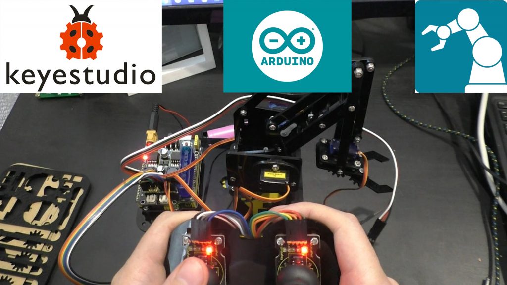
Набор можно найти тут: http://alii.pub/5w88cr
Для данного конструктора есть инструкция и много примеров для работы. Перейти по ссылке чтоб ознакомиться: https://wiki.keyestudio.com/Ks0198_keyestudio_4DOF_Robot_Mechanical_Arm_Kit_for_Arduino_DIY
Мне же в тех примерах не понравилось, то что у данного конструктора управление сделано на джойстиках. Это очень не удобно. Тяжело сделать точные движения.
Я решил переделать управление на потенциометры. Взял 4 потенциометра на 10 кОм. Каждый потенциометр отвечает за свою серву.
Схема подключения получилась следующая:
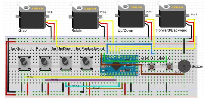
Программа еще умеет запоминать движения. Точнее положение сервоприводов в момент в момент нажатия кнопки.
В общем левая кнопка запоминает положение руки. А правая кнопка потом воспроизводит.
Программу можно скачать вот отсюда: https://disk.yandex.ru/d/eDyrMgohlpxarA
Так же хочу сказать, что данная рука является копией opensourse проекта eezybotarm. Для него существуют файлы для 3д печати. Их можно найти тут: https://www.thingiverse.com/thing:1454048
Ну а выглядит распечатанная рука вот так:
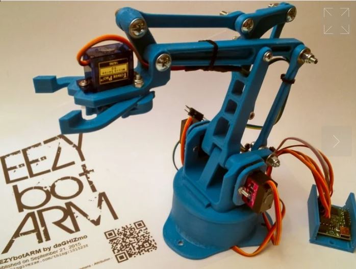
Ну и сборка и небольшое объяснение работы как и демонстрация. Это все можно посмотреть в видео ниже:
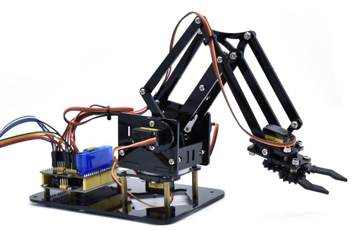
1. Overview
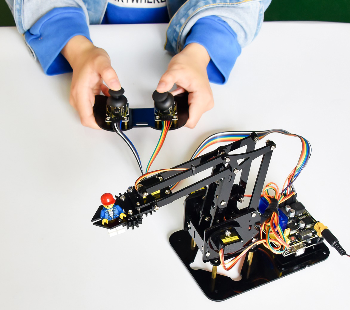
DIY is the activity of making or repairing things yourself, especially in your home. Historically, it has been popular all over the world since 1960s, making our routine life interesting.Combined with STEM education, DIY products can greatly cultivate teenagers’ imagination and creativity.
Therefore, we Keyestudio R&D group rolls out an amazing 4DOF mechanical arm kit, which contributes to improving kids’hand-on ability, logical thinking and observation ability.
Tutorial and code download address:KS0198X Tutorial
It is easy to build to say the least. In fact, the four servos of this robot arm are controlled by V4.0 control board and two joystick modules. What’s more, the detailed tutorials are provided for you even you are a starter.
For this mechanical robot arm, there are three methods to control. The first one is controller handle we provide(joystick modules), the second one is App; and the third one is wireless PS2 joystick module(not included in this kit).
I believe that you can’t help getting down with this kit.
Next, let’s get started.
2. Features
You can check out these features:
-
Detailed installation instructions
-
Detailed debugging methods, starting Arduino from entry.
-
Three controlling methods: Wired JoyStick Control; Phone Bluetooth Control;
Wireless PS2 JoyStick Control.
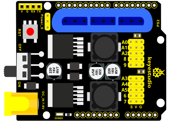
The parameters of keyestudio servo motor/ drive shield are as follows:
-
VIN voltage: VIN = DC 7-15V
-
VIN current: 5A
-
Two-channl 5V output: 5V/3A
-
PS2 interface: compatible with Sony PS2 receiver, can be plugged directly
into the expansion board. -
Dimensions: 73*53.34mm
3. Kit List
You can see a pretty beautiful packaging box for the arm kit, and inside the packaging you will find all the parts and screws listed below.
Note: Peel the plastic film off the board first when you install robotic arm.
|
No. |
Item |
QTY |
Picture |
|---|---|---|---|
|
1 |
Keyestudio V4.0Control Board |
1 |
 |
|
2 |
Keyestudio Servo Motor Driver Shield |
1 |
 |
|
3 |
Acrylic Boards |
1 |
 |
|
4 |
Acrylic Handle |
1 |
 |
|
5 |
MeArm ABS Cylindrical Holder |
1 |
 |
|
6 |
180° Black Servo |
4 |
 |
|
7 |
BT-24 Module |
1 |
 |
|
8 |
Keyestudio Joystick Module |
2 |
 |
|
9 |
3D PS2 Joystick Cap |
2 |
 |
|
10 |
3*40MM Screwdriver |
1 |
 |
|
11 |
Galvanized Wrench |
1 |
 |
|
12 |
M3*6MM Round Head Screws |
12 |
 |
|
13 |
M3*10MM Round Head Screws |
22 |
 |
|
14 |
M3*14MM Flat Head Screws |
2 |
 |
|
15 |
M3*12MM Round Head Screws |
12 |
 |
|
16 |
M3*24+6MM Copper Pillar |
4 |
 |
|
17 |
M3*6mm+6mm Copper Pillar |
10 |
 |
|
18 |
M3 Stainless Steel Hex Nuts |
22 |
 |
|
19 |
M3 Hexagon Nuts |
24 |
 |
|
20 |
M1.2x5MM Phillips Self-tapping Screws |
8 |
 |
|
21 |
M2x5MM Phillips Self-tapping Screws |
10 |
 |
|
22 |
M3 304 Stainless Steel Flat Washer |
10 |
  |
|
23 |
M2x8MM Phillips Self-tapping Screws |
2 |
 |
|
24 |
M3*16MM Flat Head Screws |
2 |
 |
|
25 |
Male-Female 10CM Jumper Wire |
4 |
 |
|
26 |
Female- Female 50CM Jumper Wire |
10 |
 |
|
27 |
Black 3*100MM Cable Ties |
7 |
  |
|
28 |
18650 2-Slot Battery Holder |
1 |
|
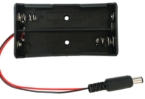
4. Assembly Guide
(1) Install the base of the robotic arm
Components Needed:
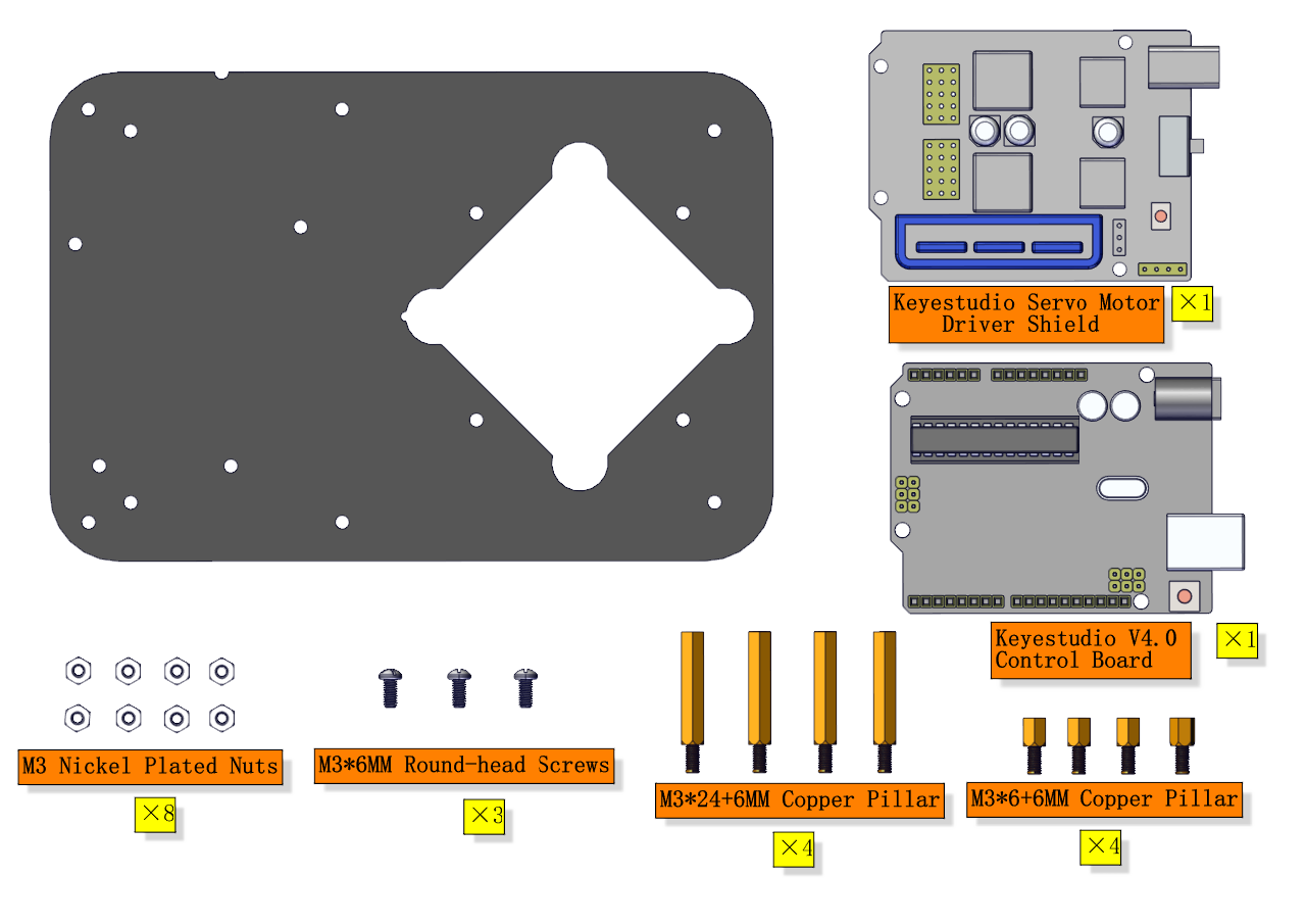
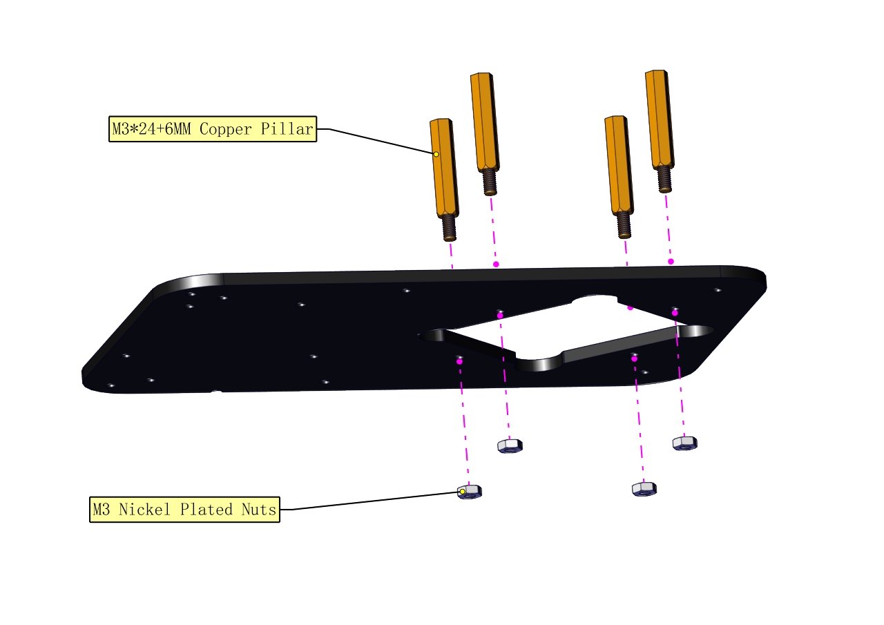
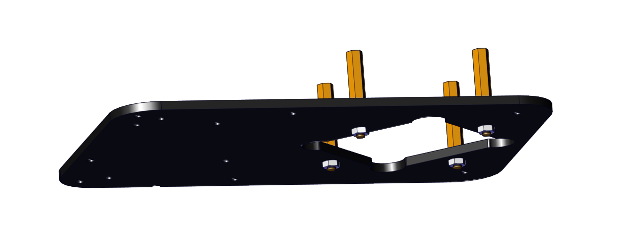
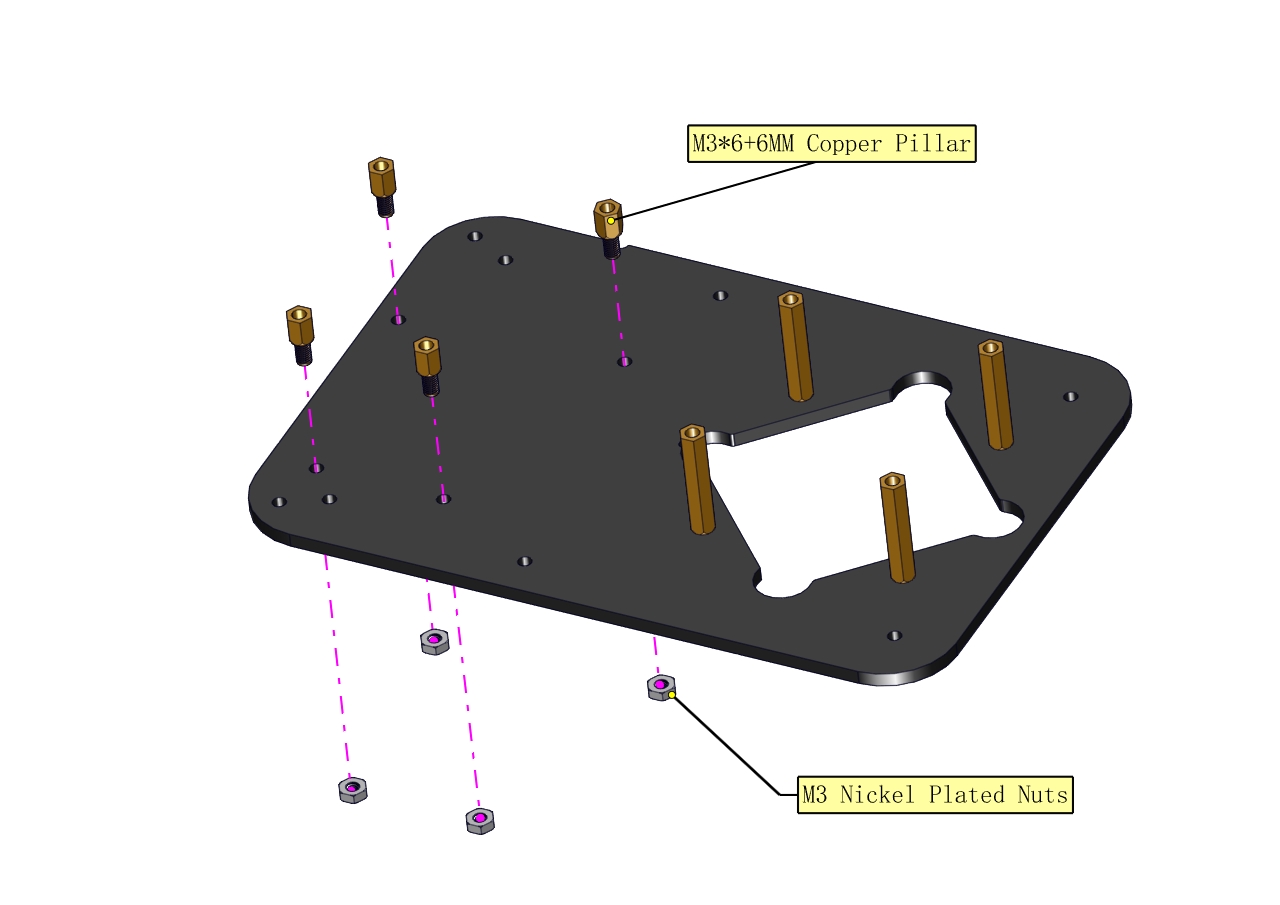
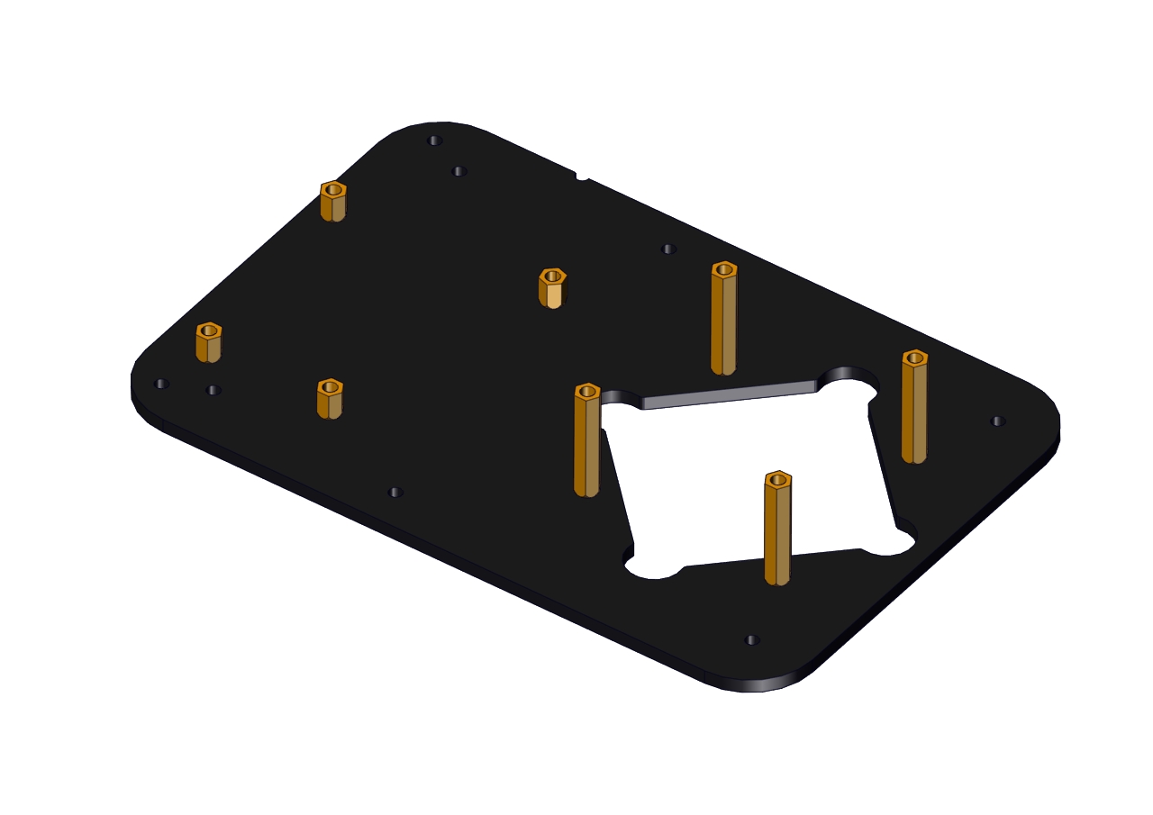
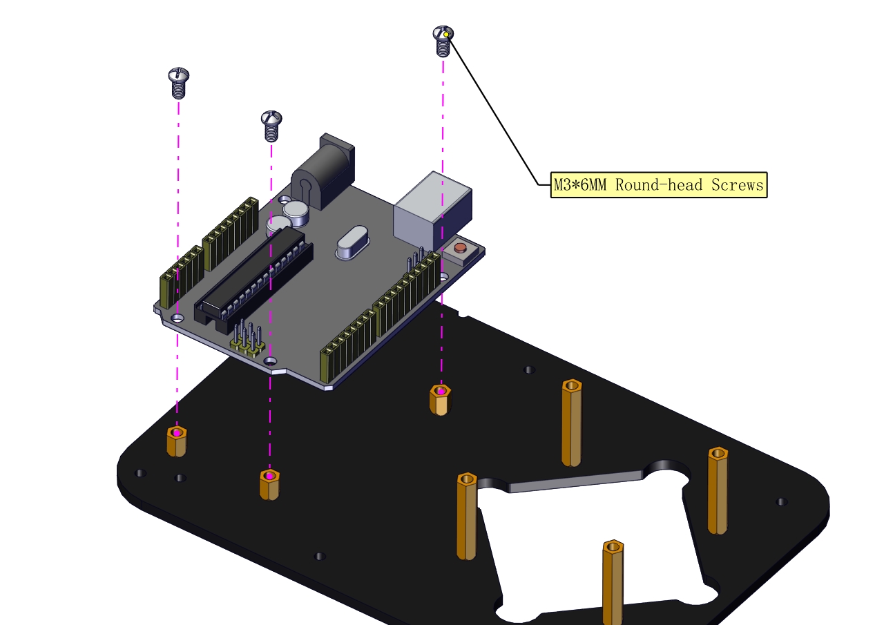
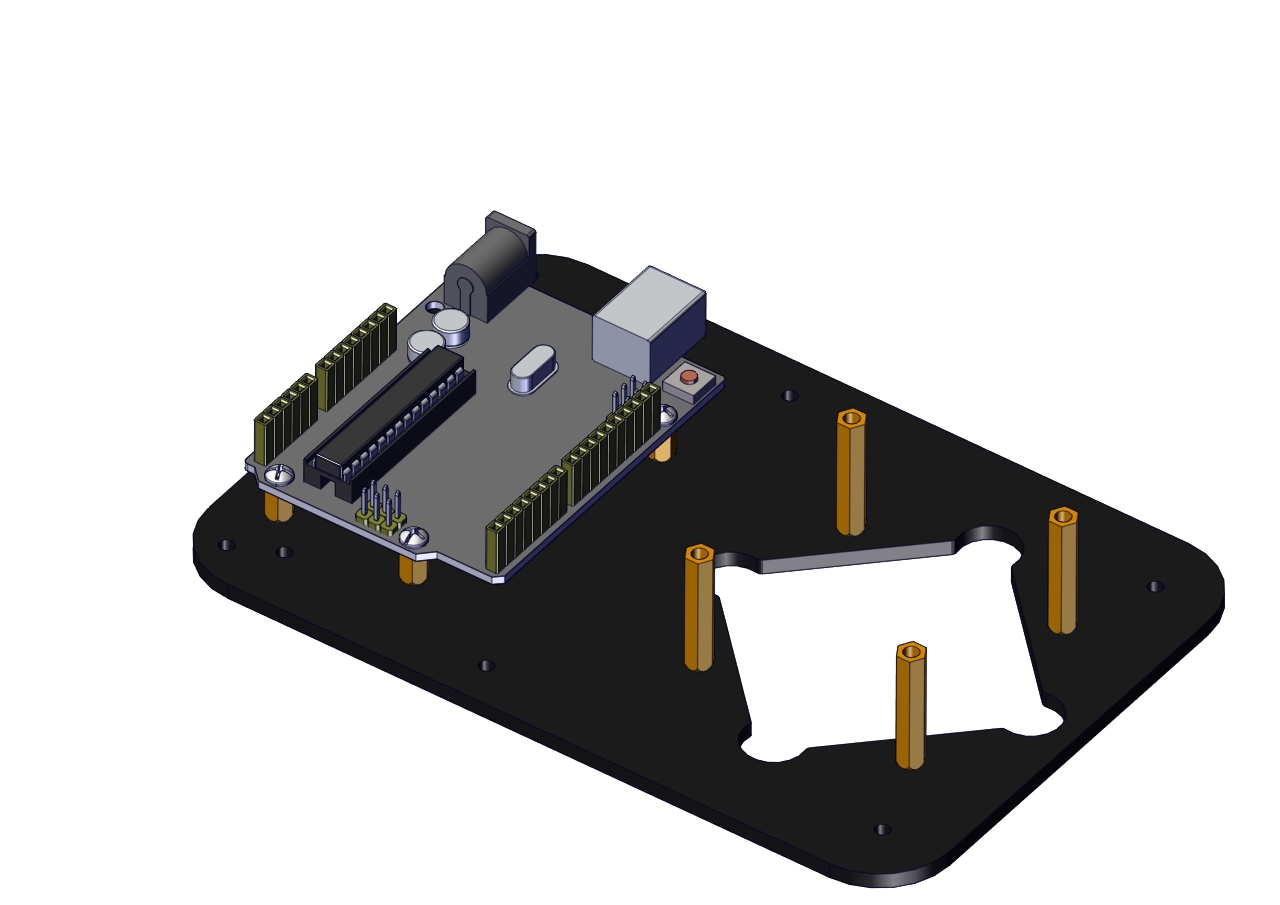
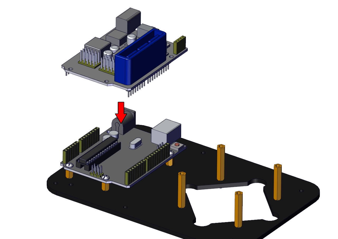
The base is installed successfully.
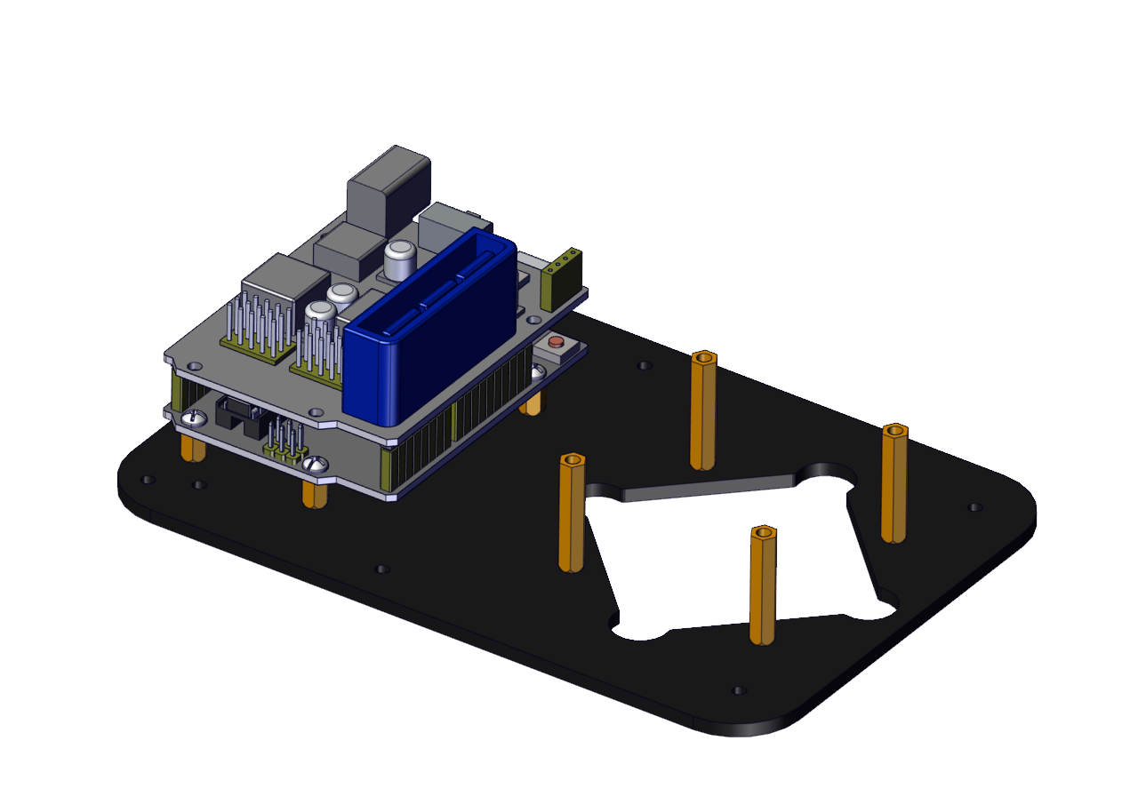
(2) Mount servos onto the base
Components Needed:
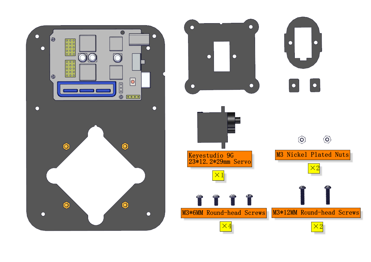
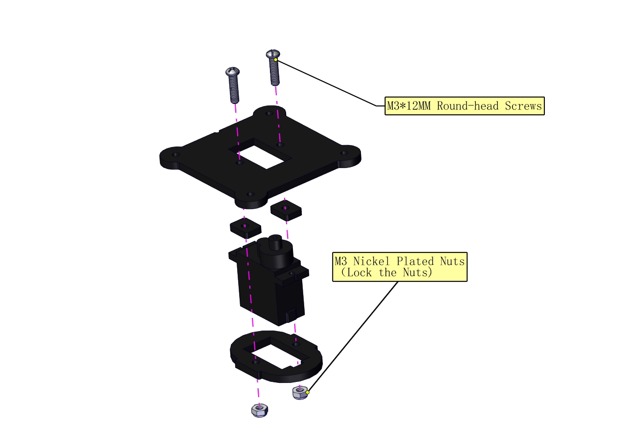
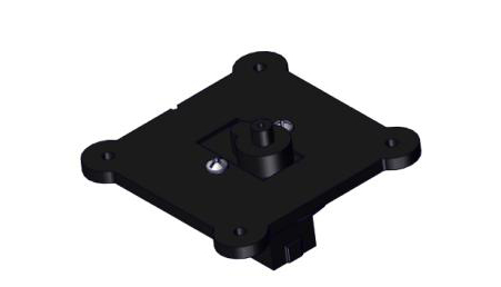
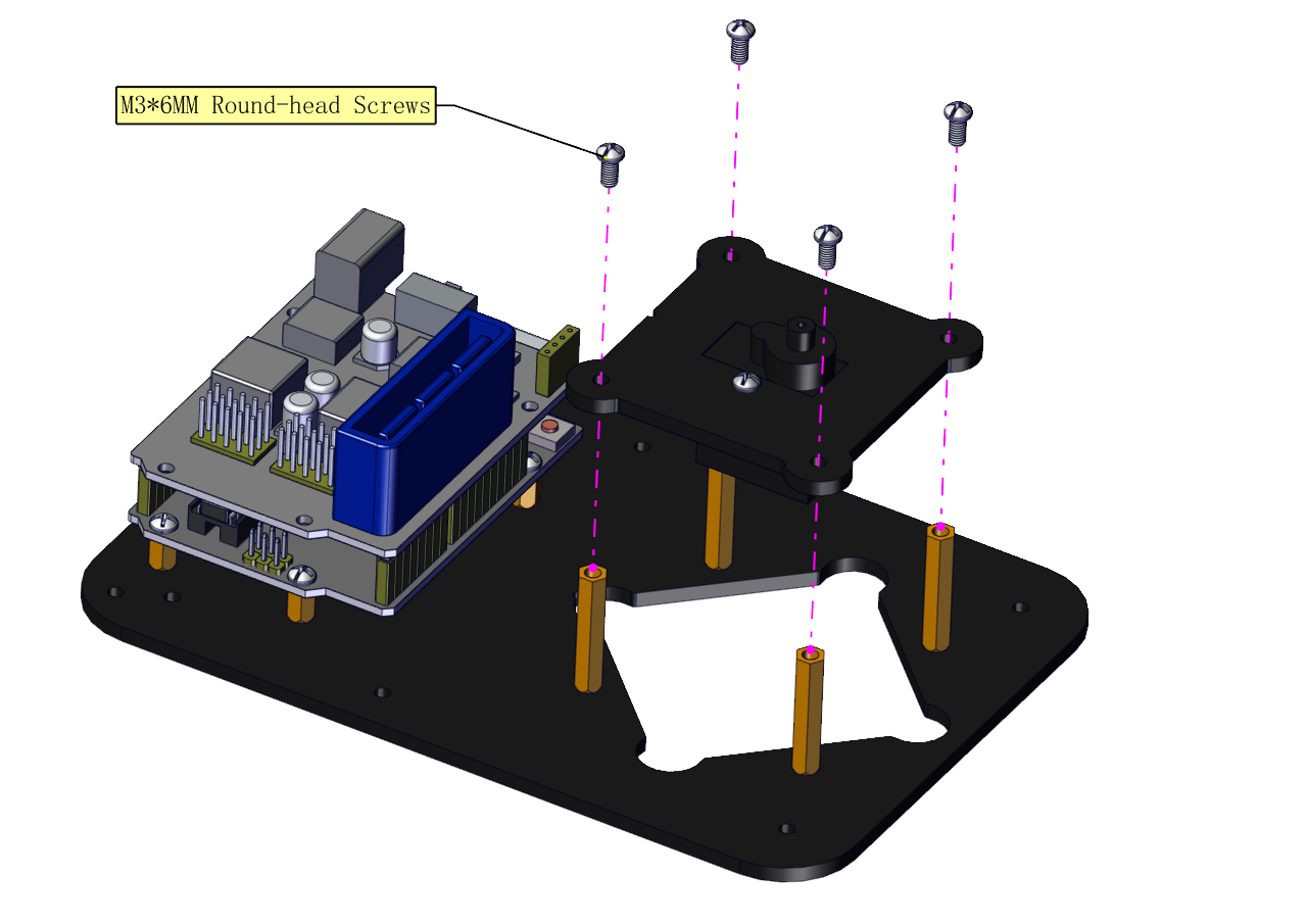
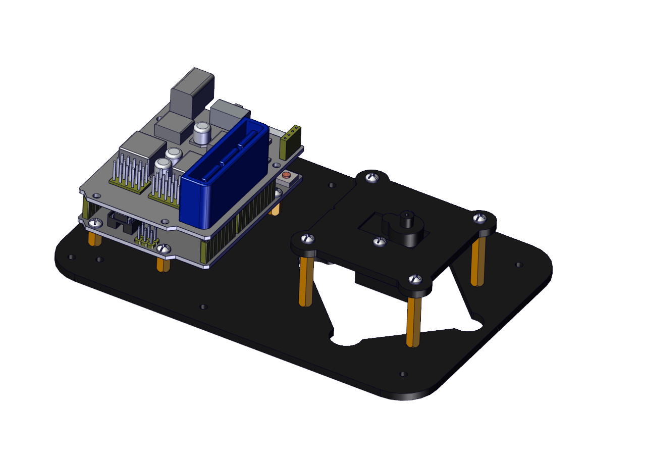
Assemble a servo(left) onto the left board
Components Needed:
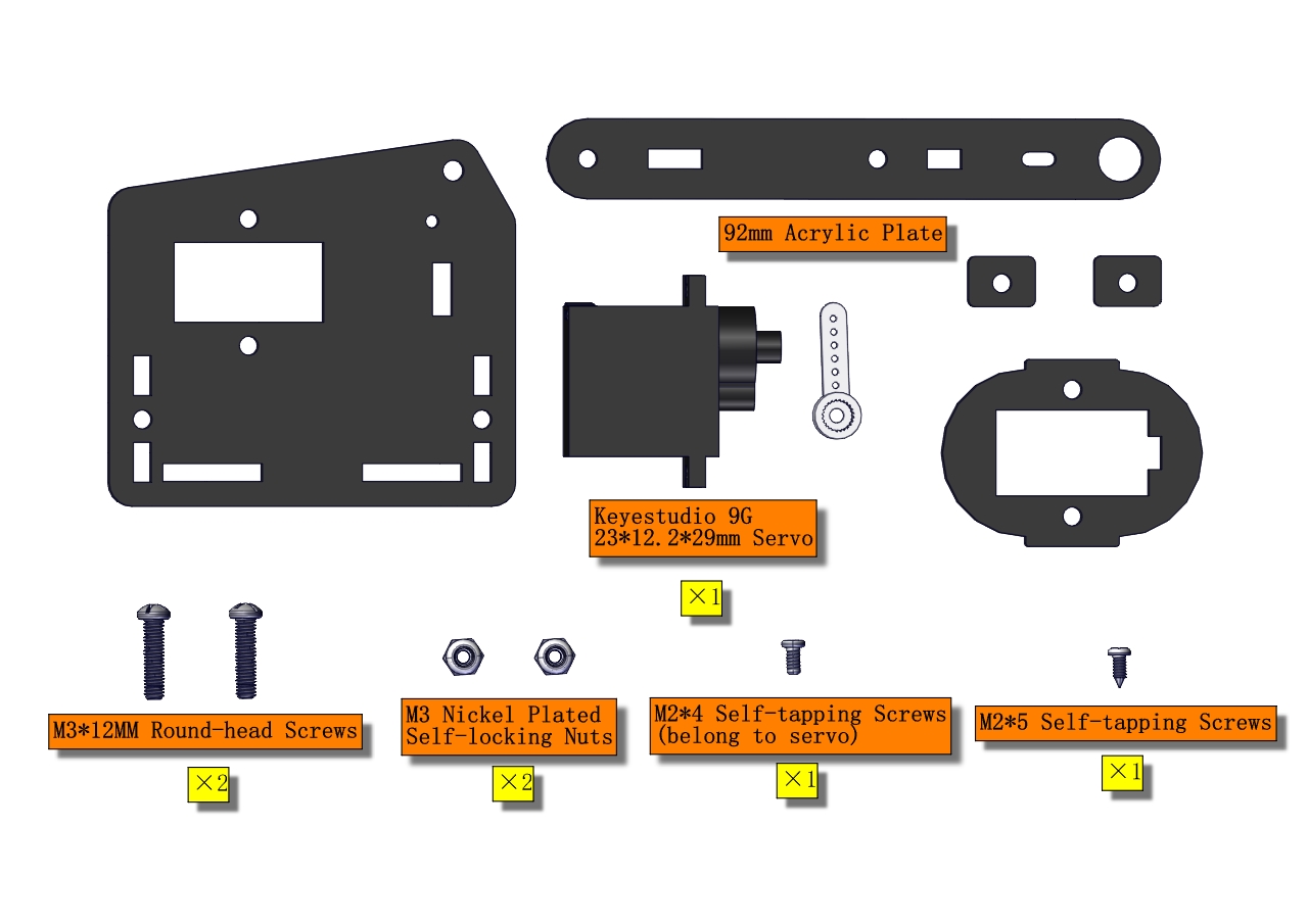
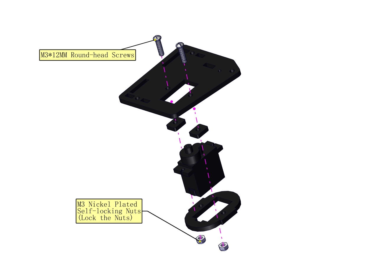
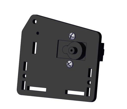
Initialize the left servo
Attach this left servo to G, V and S(6)of servo motor driver shield, upload the following code, plug in power and press the rest button on the V4.0 board. Then the left servo rotates to 180°
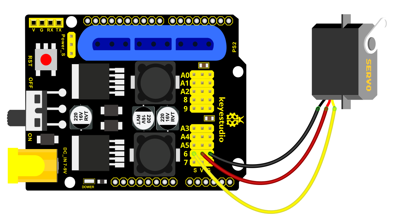
Test Code:
#include <Servo.h>
Servo myservo; // create servo object to control a servo
void setup()
{
Serial.begin(9600);
delay(1000);
}
void loop()
{
myservo.attach(6); // Change pin to adjust one by one
myservo.write(180); //Angle
delay(1000);
}

a. Fix the arm:
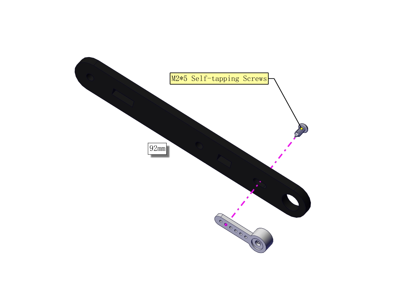

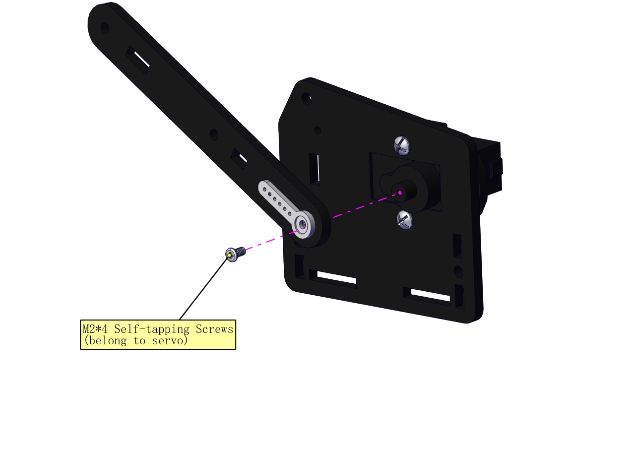
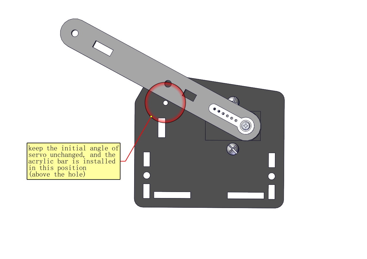
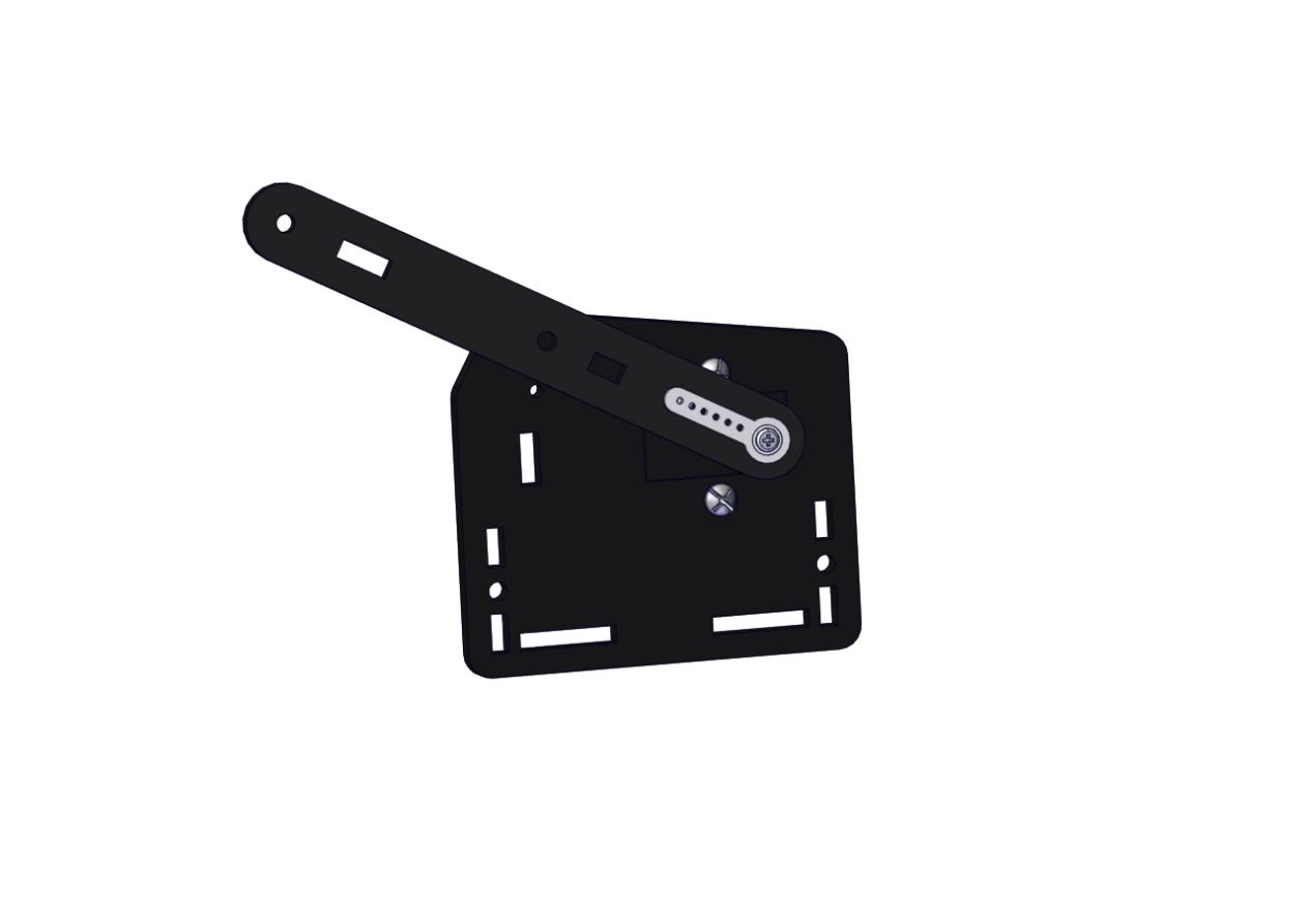
Mount a servo(right) onto the right board
Components Needed
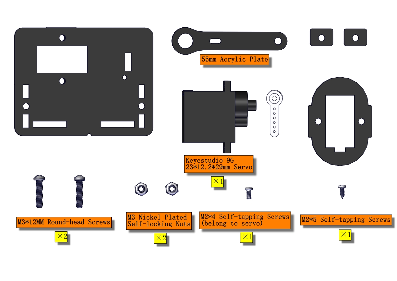
Note the breach direction of acrylic board
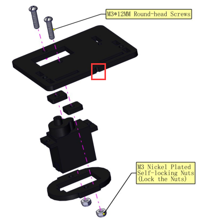
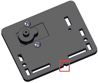
b. Initialize the right servo
Attach this left servo to G, V and S(A0)of servo motor driver shield, upload the following code, plug in power and press the rest button on the V4.0 board. Then the left servo rotates to 0°
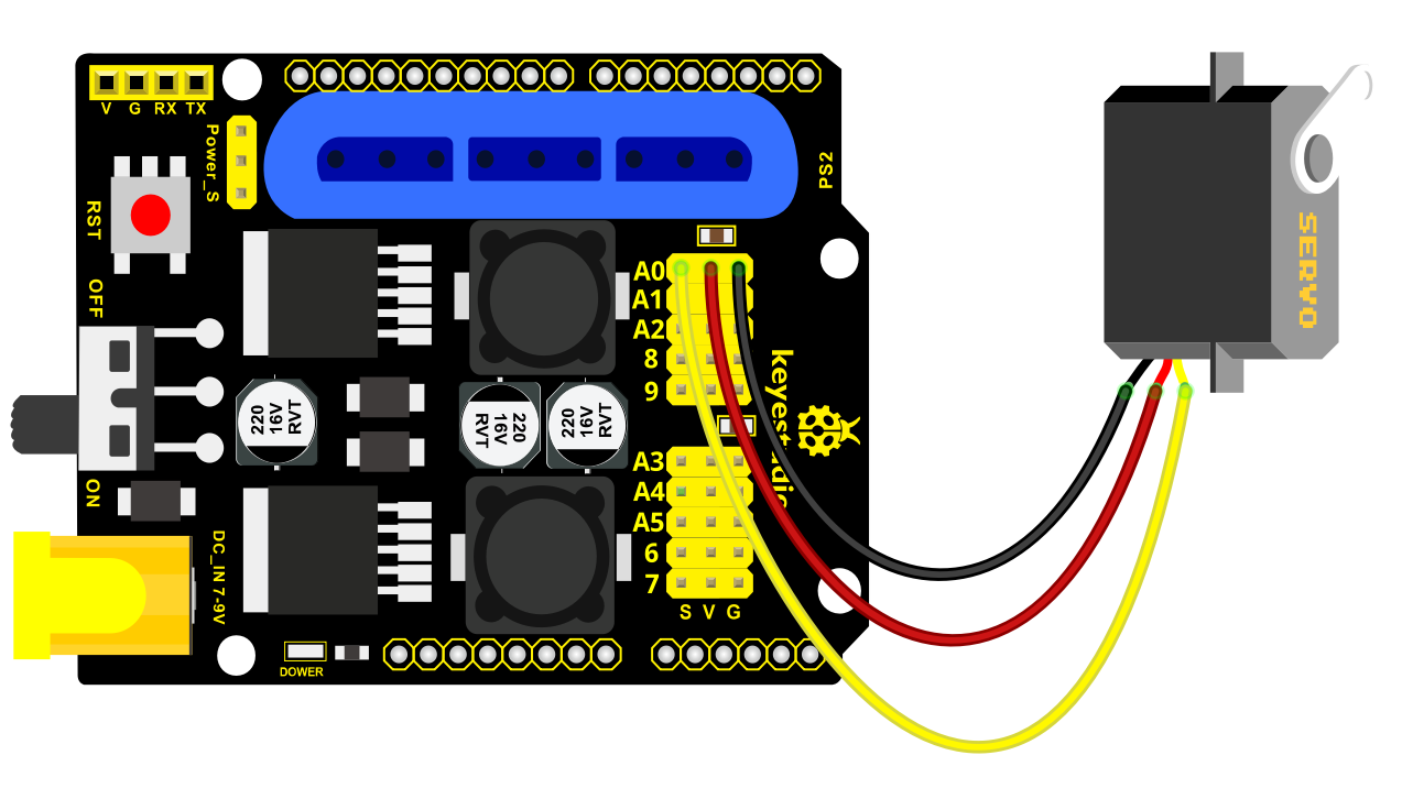
Set the servo to 0°:
#include <Servo.h>
Servo myservo; // create servo object to control a servo
void setup()
{
Serial.begin(9600);
delay(1000);
}
void loop()
{
myservo.attach(A0); // Change pin to adjust one by one
myservo.write(0); //Angle
delay(1000);
}
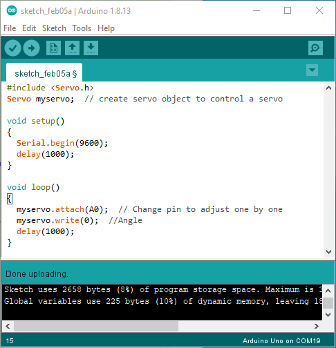
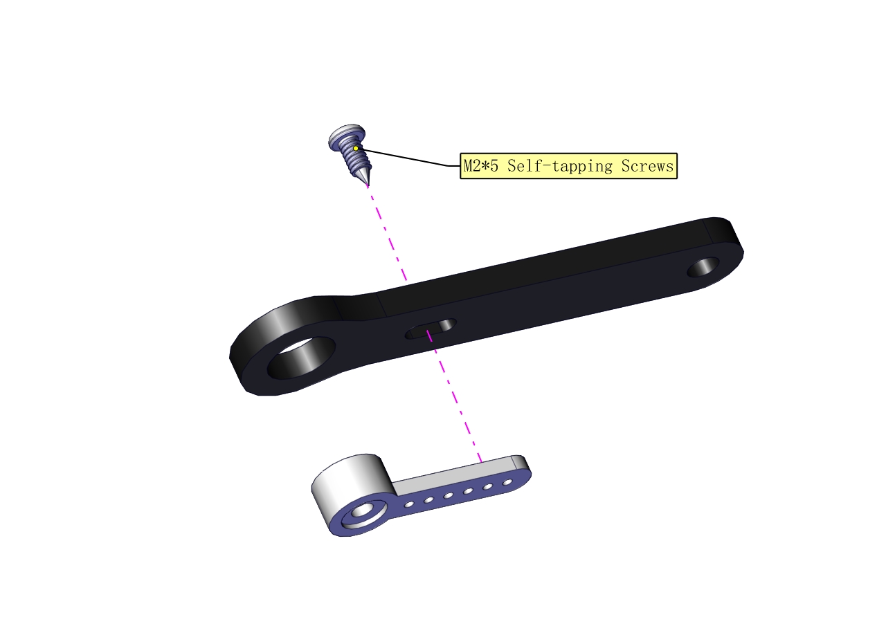
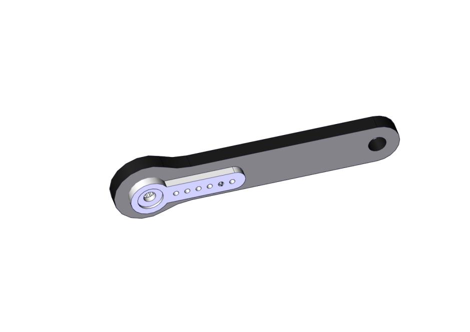
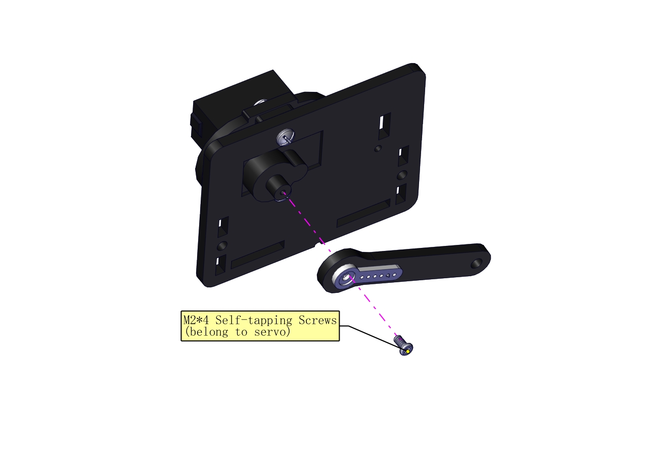
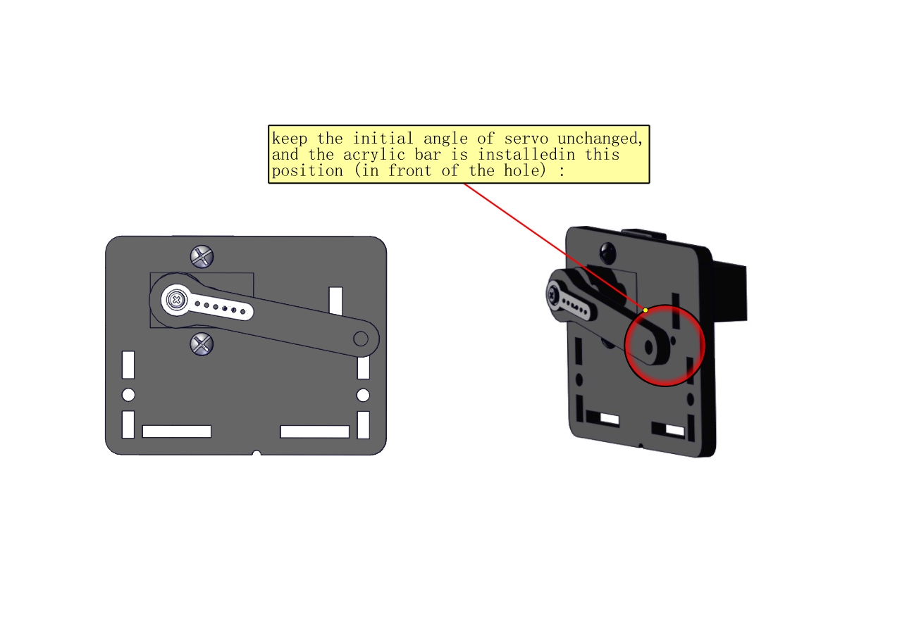
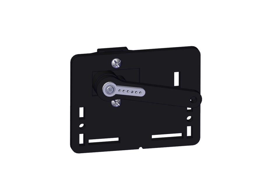
Install the holder part
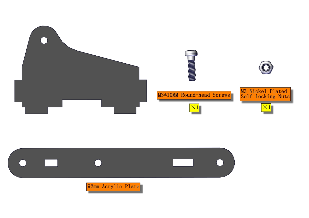
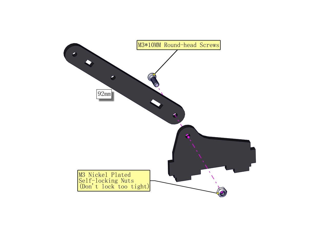
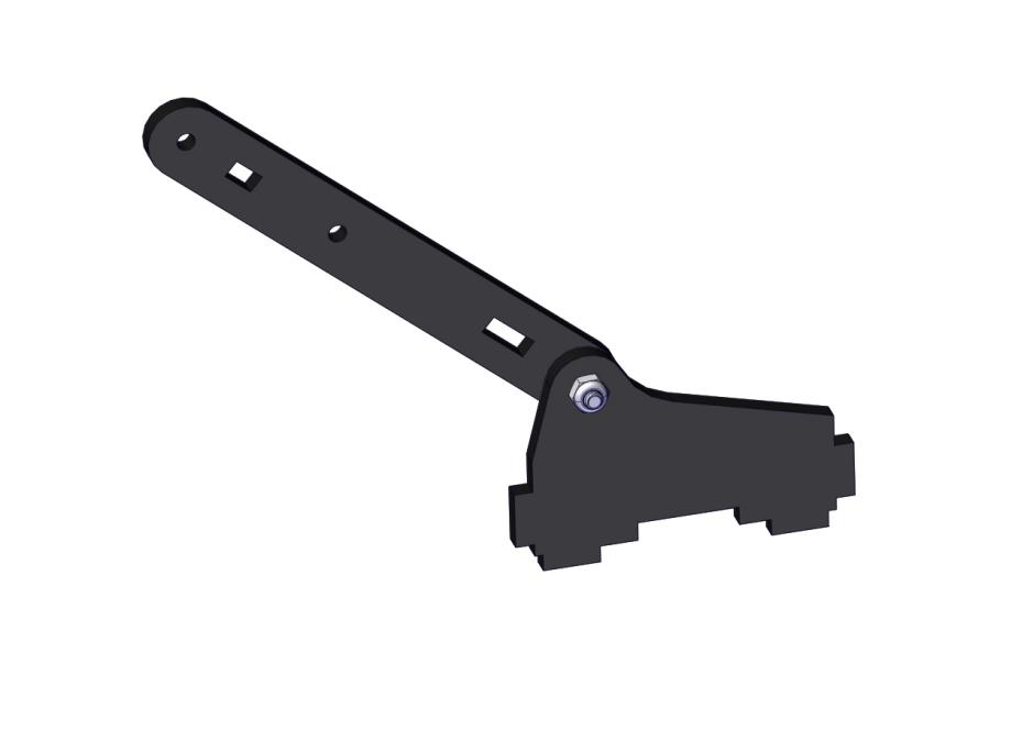
Fix the left part and the mount part together
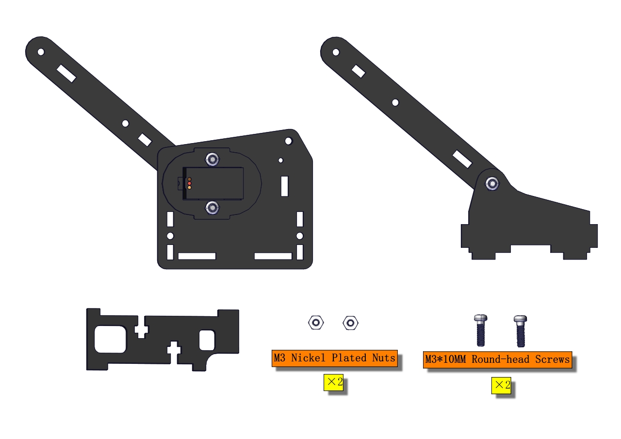
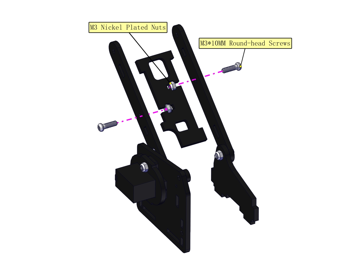
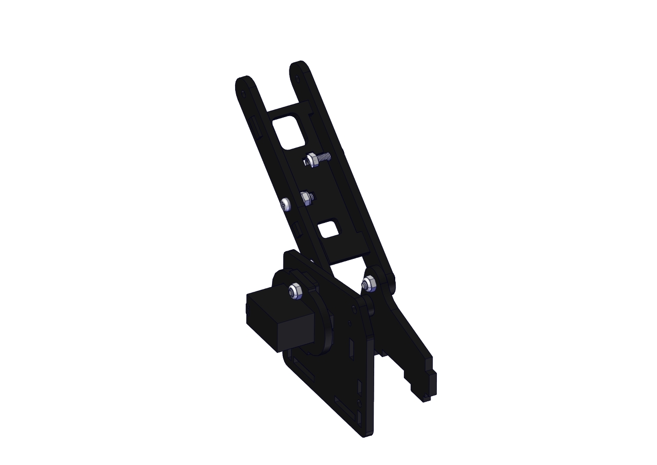
Fix the right part and the ABS holder together.
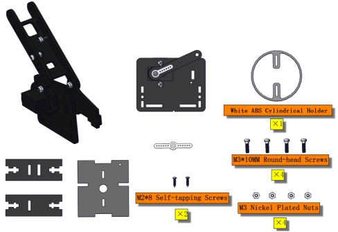
Note the direction of the ABS holder.
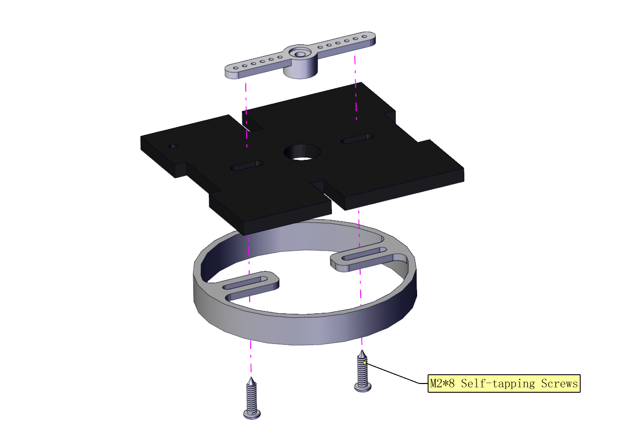
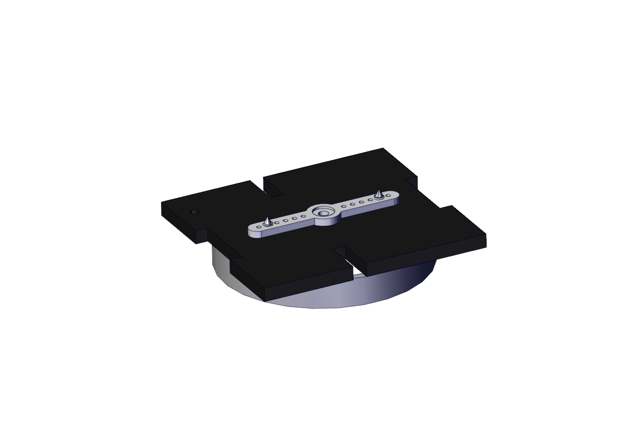
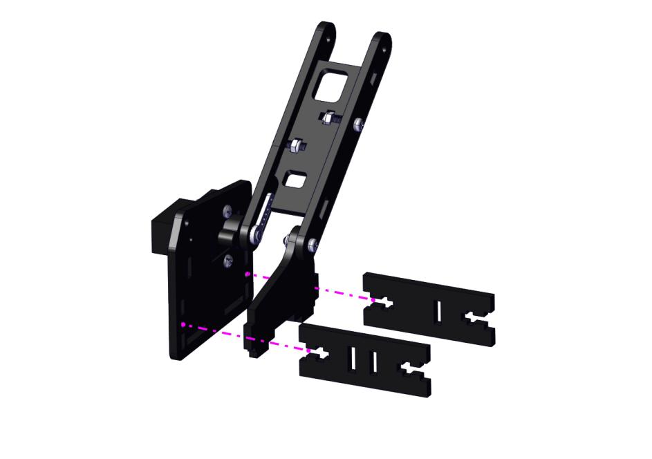
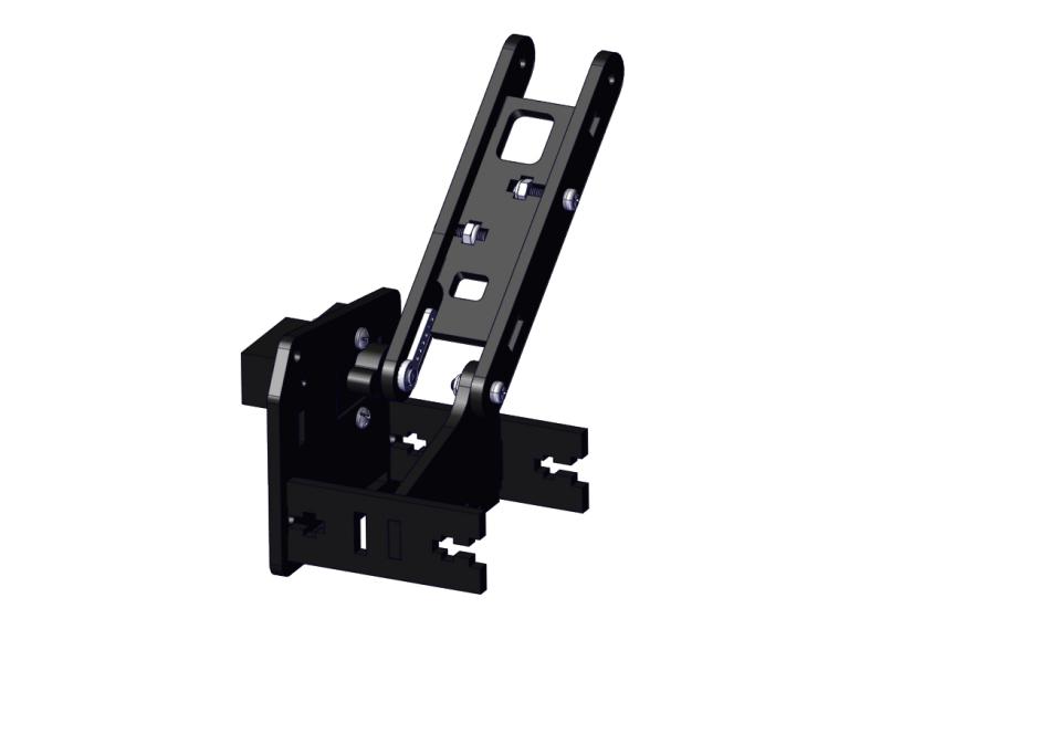
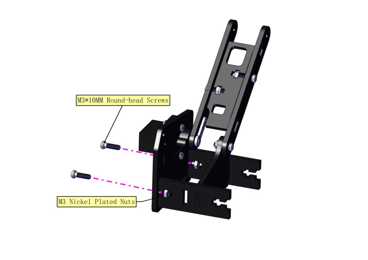
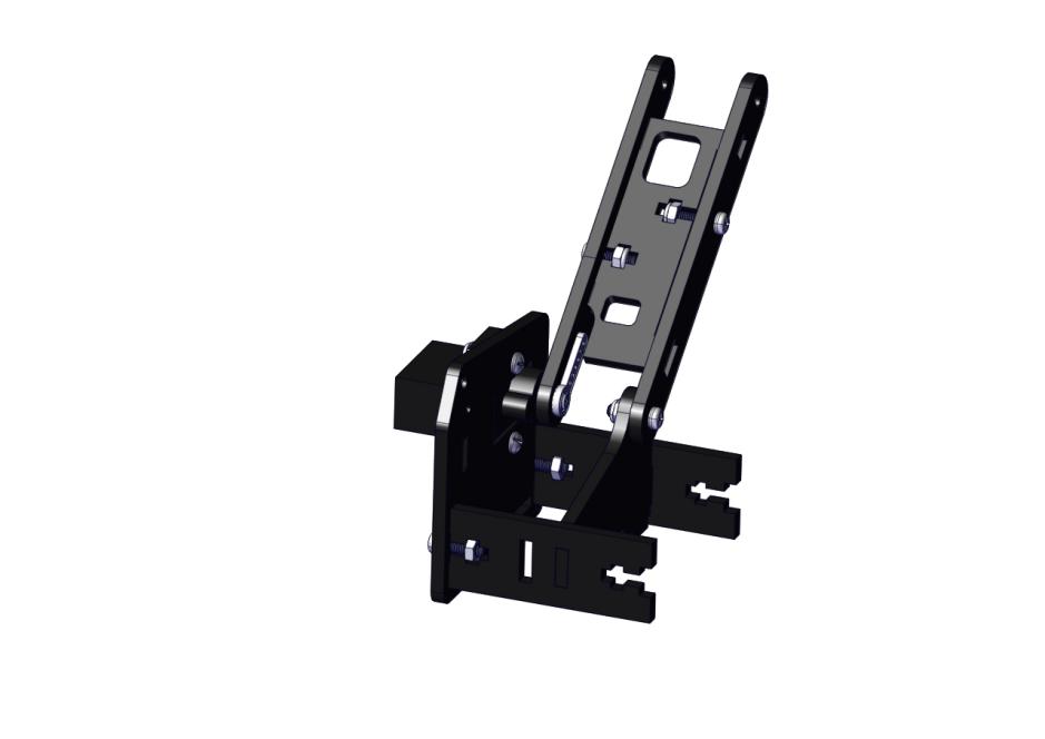
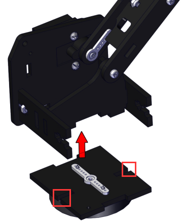
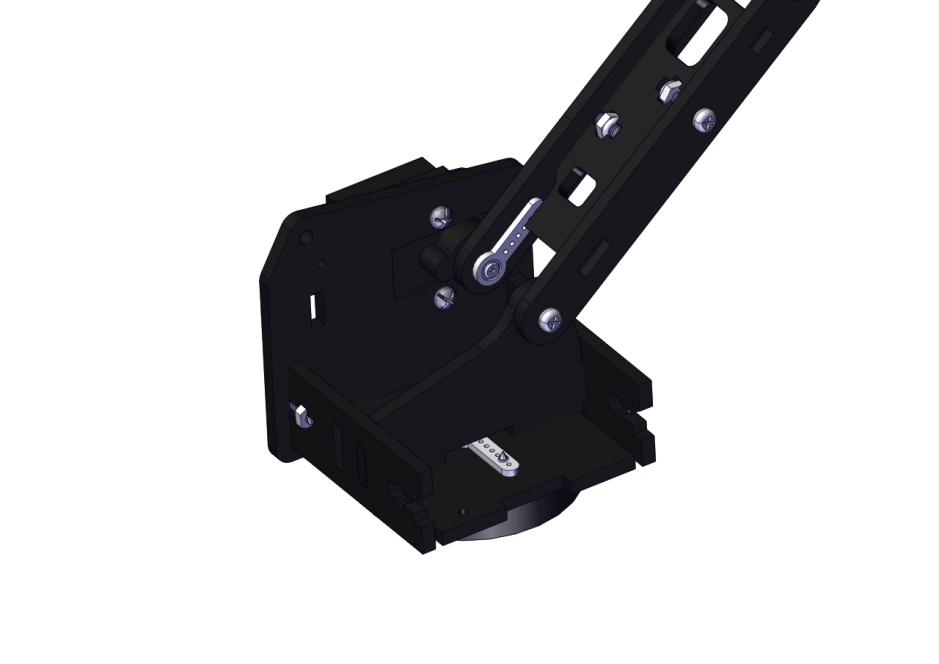
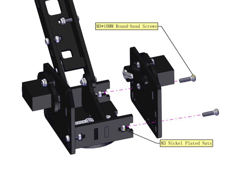
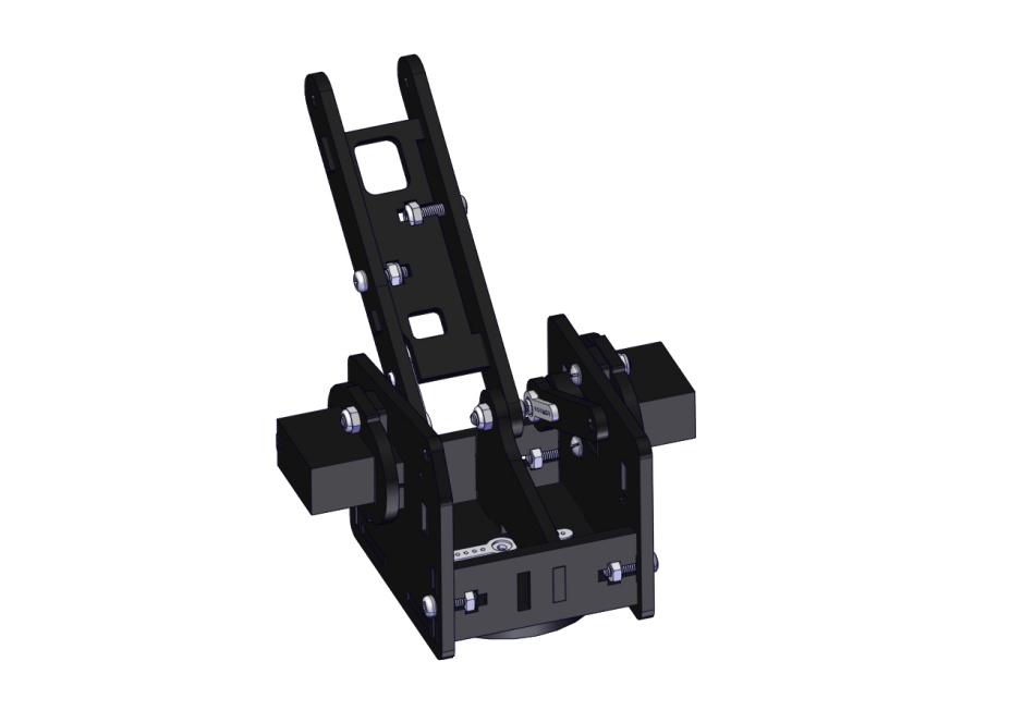
Install the middle part
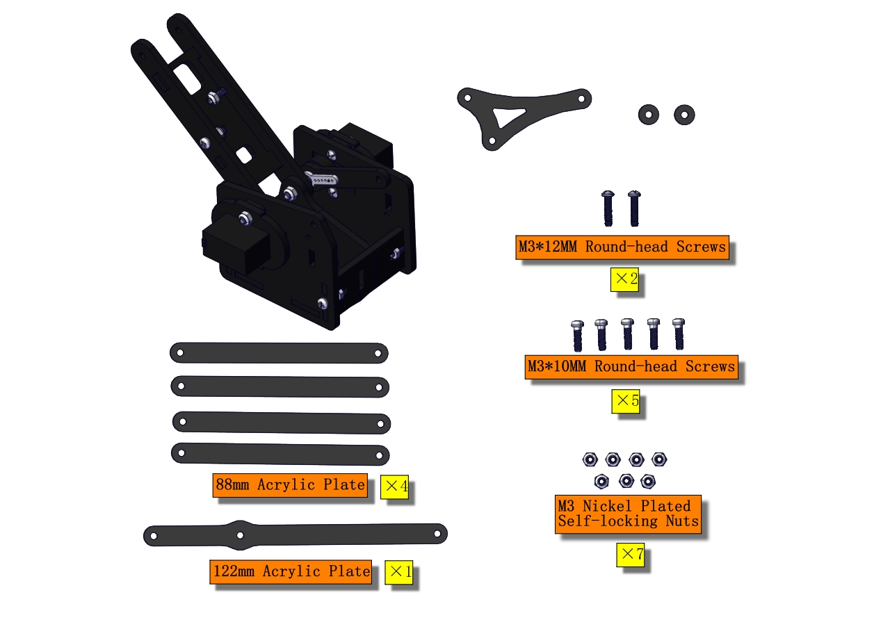
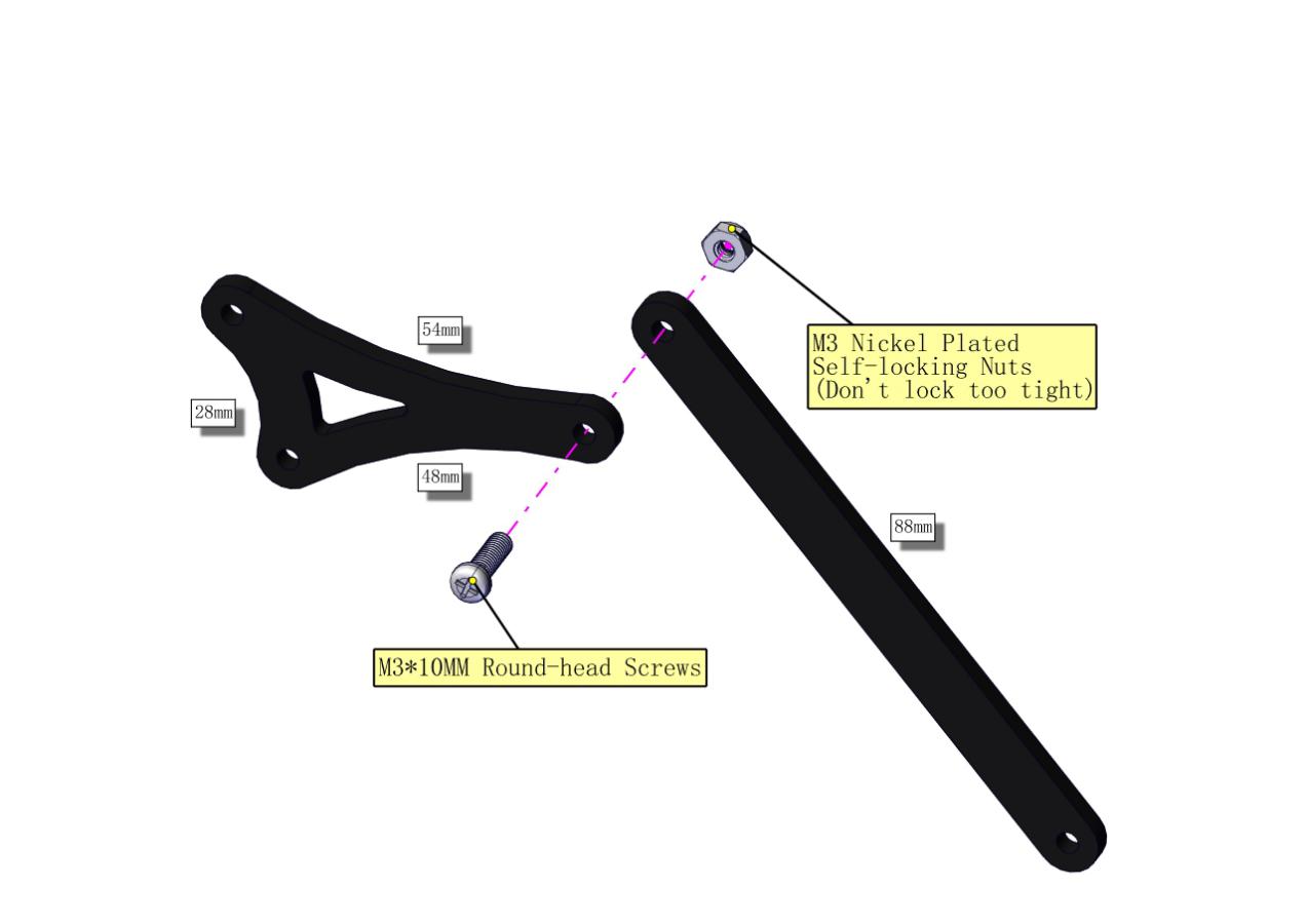

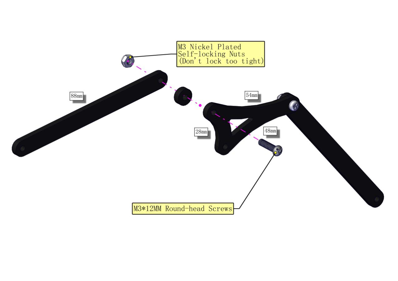

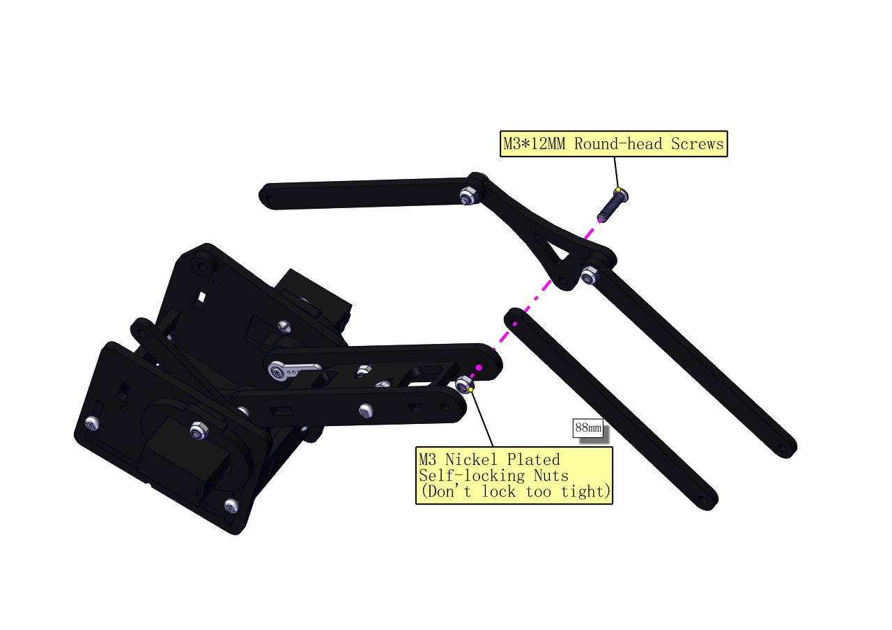
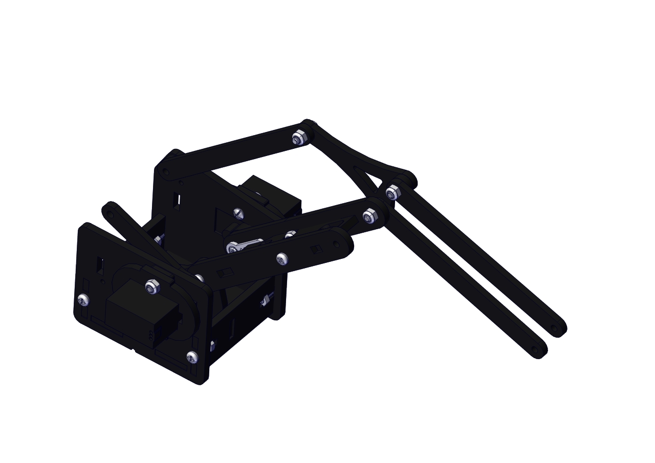
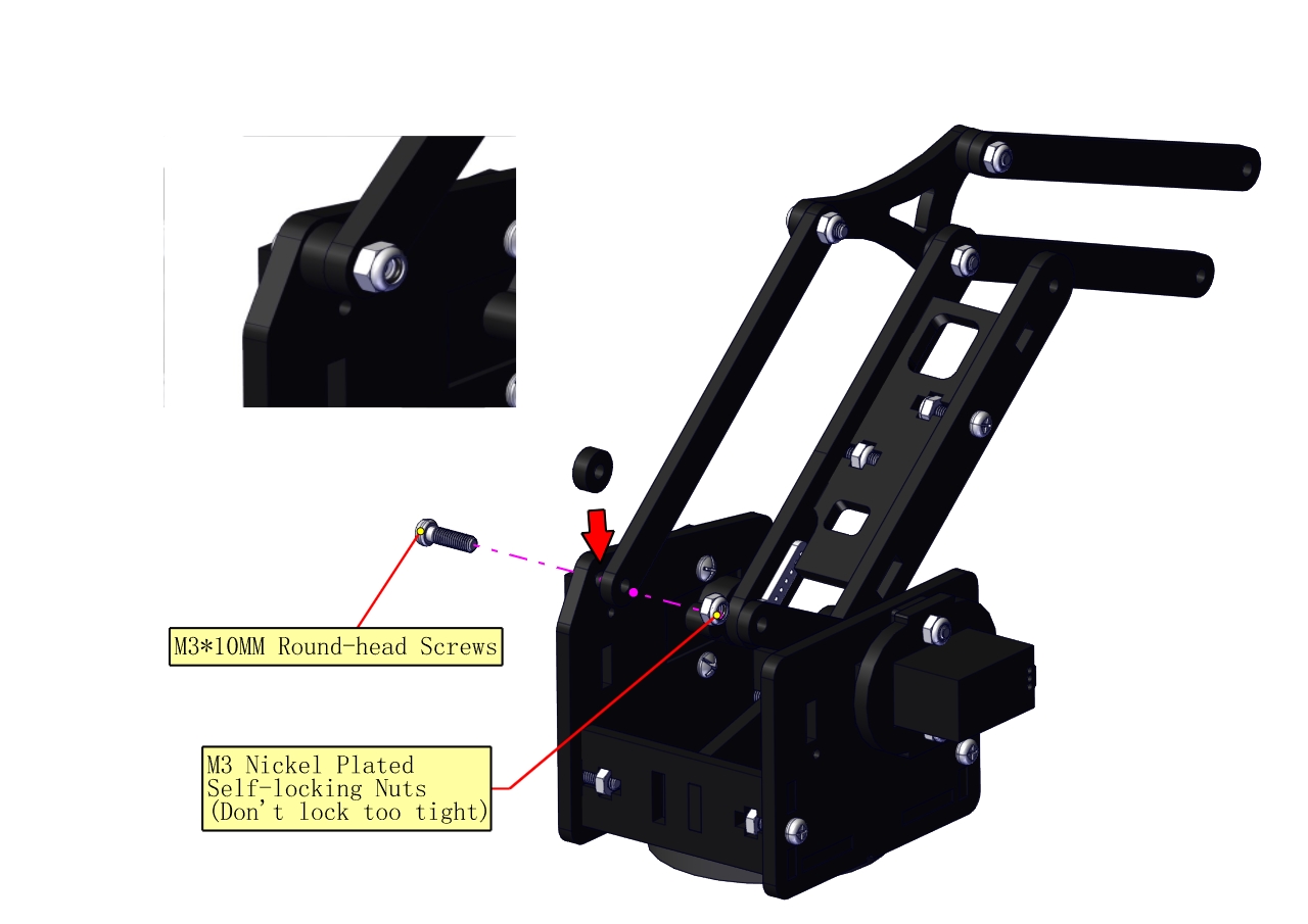
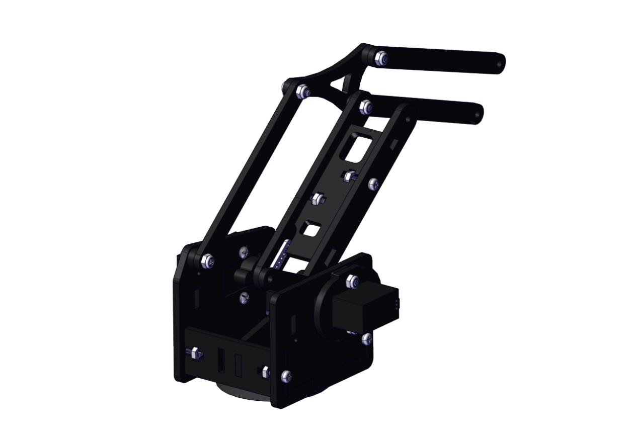
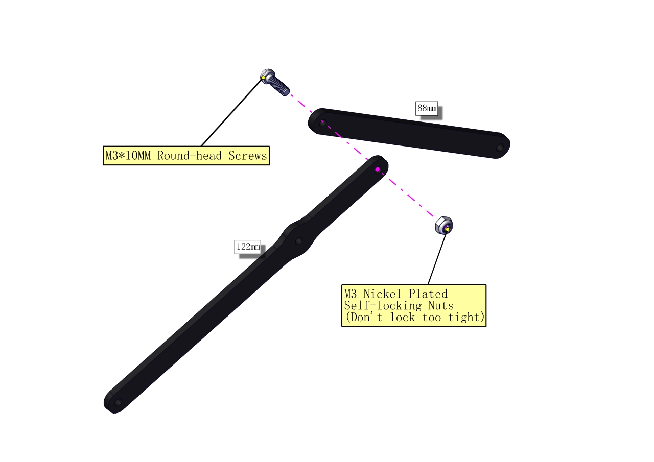

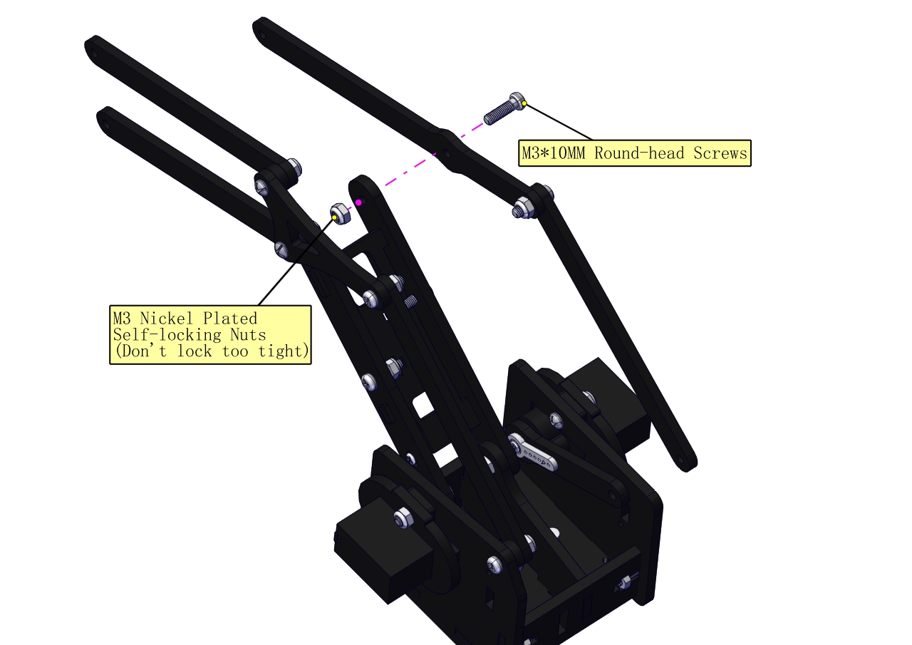
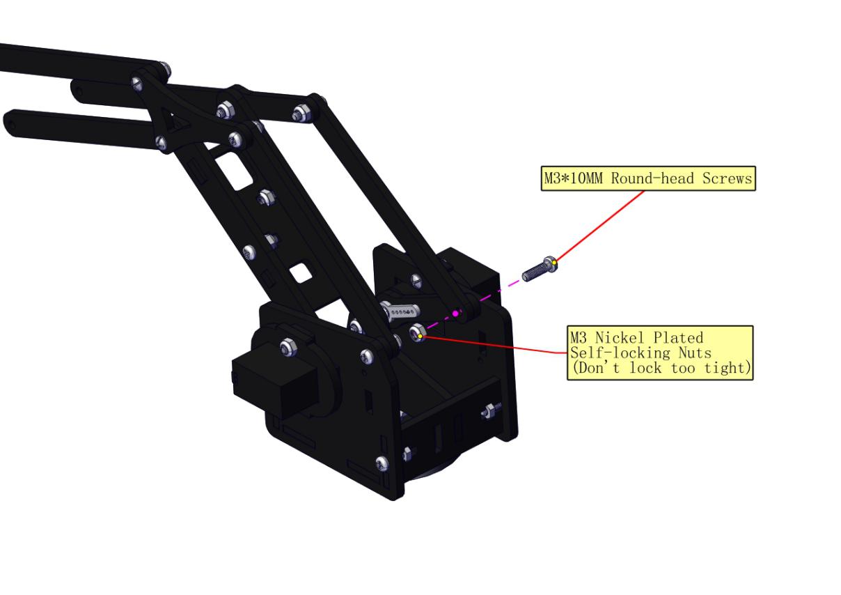
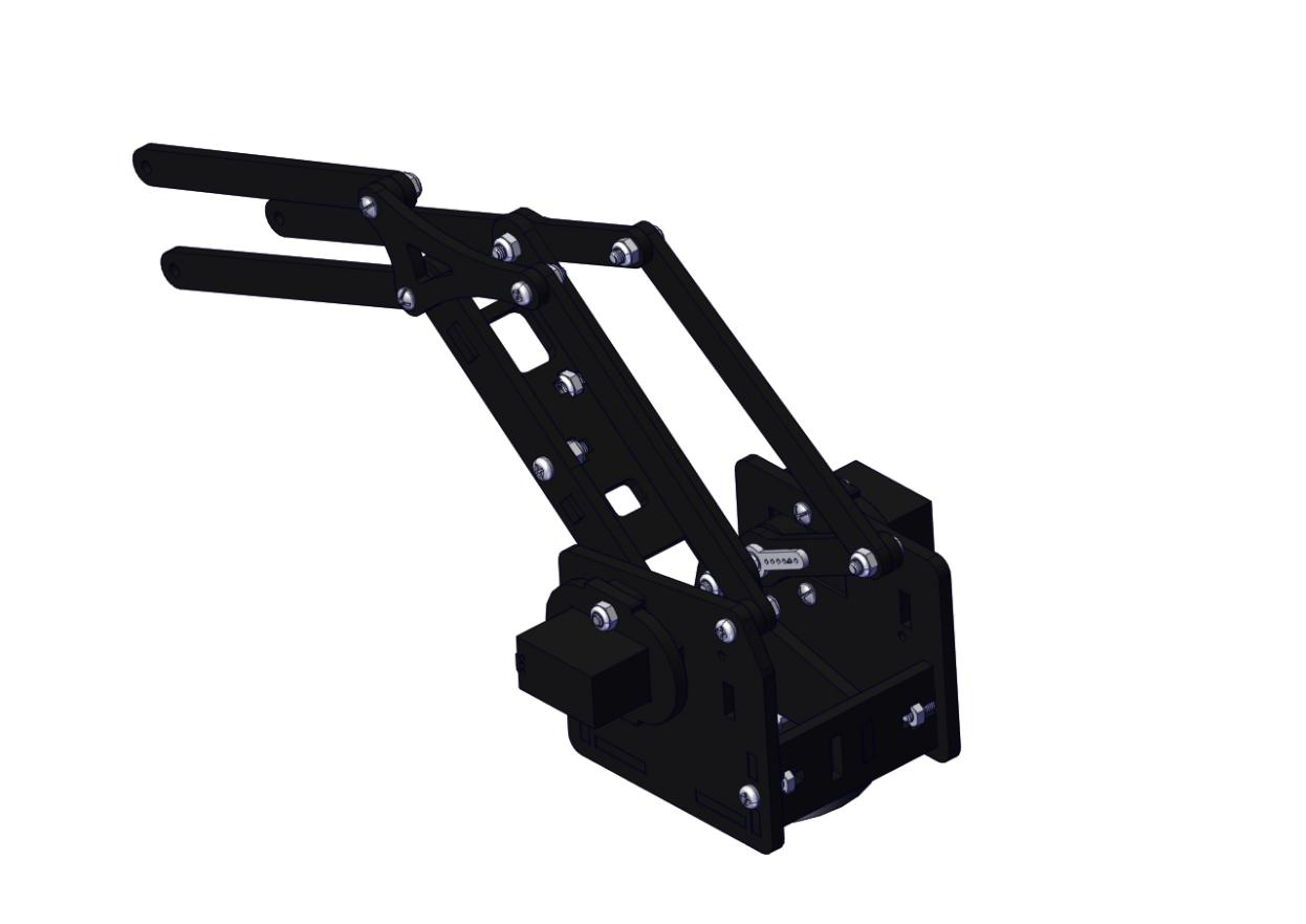
Assemble the claw
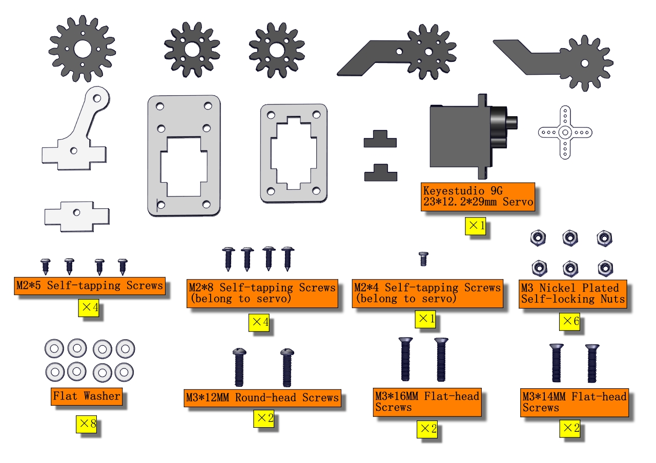
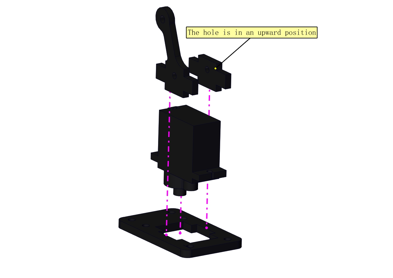
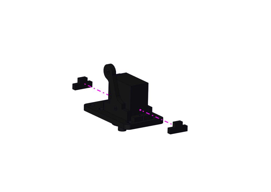
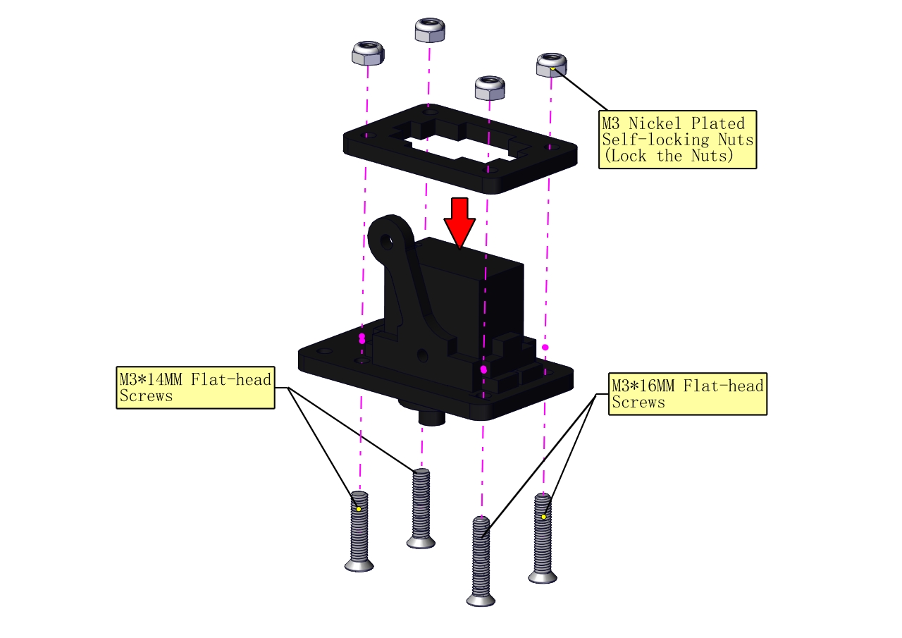
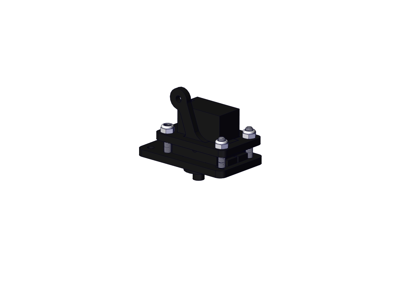
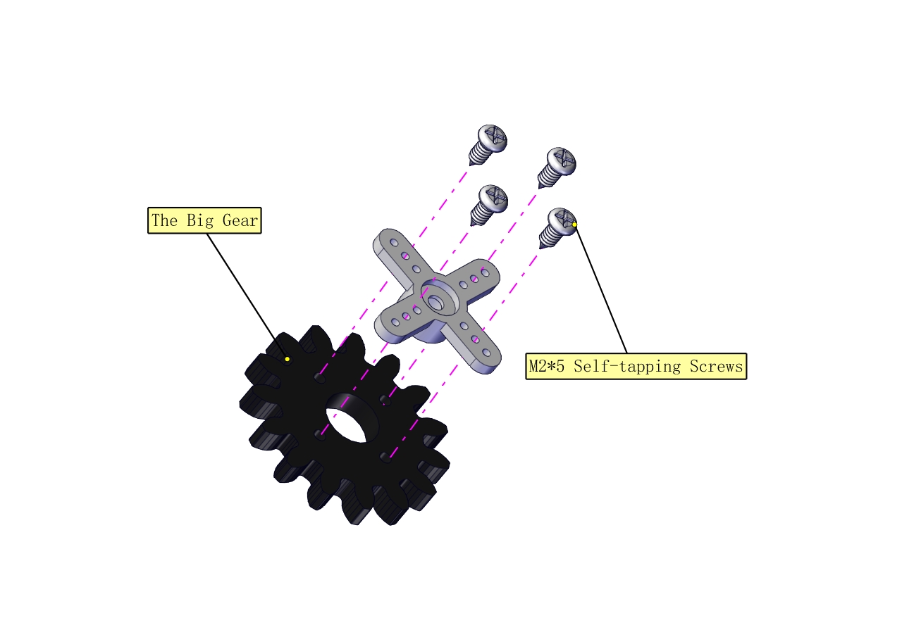
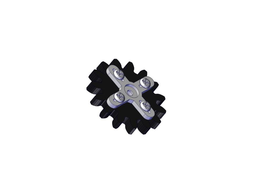
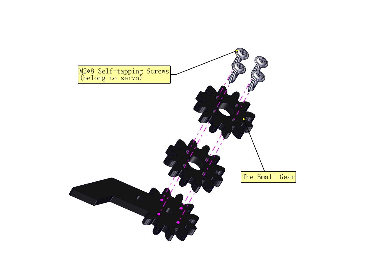
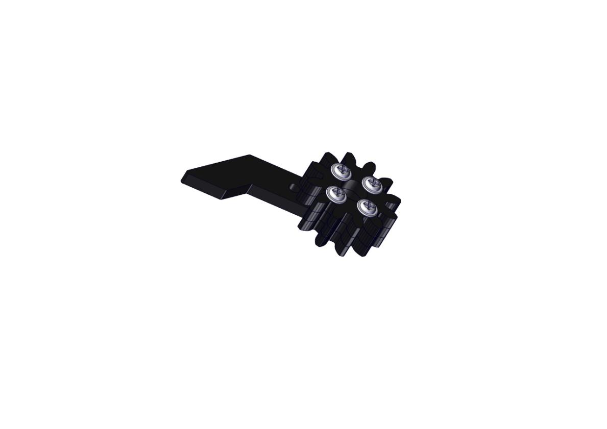
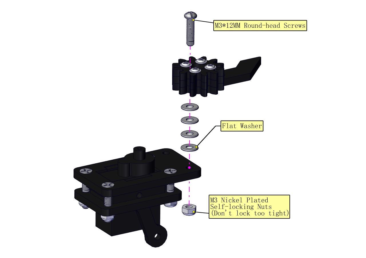
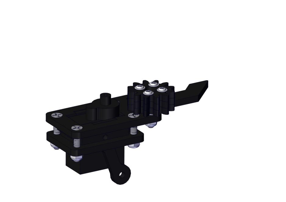
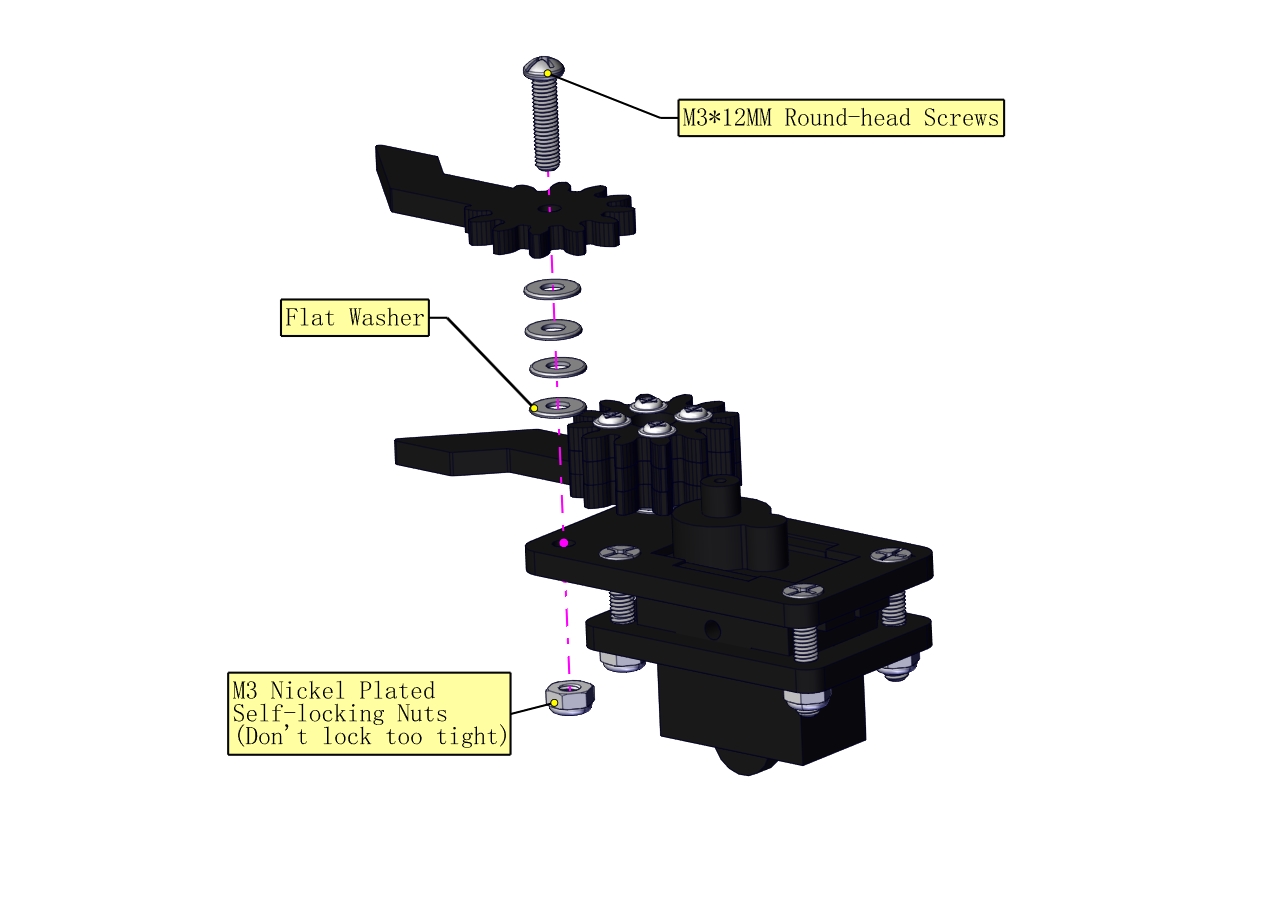
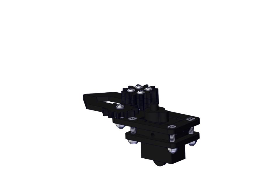
c. Initialize the servo
Attach this left servo to G, V and S(9)of servo motor driver shield, upload the following code, plug in power and press the rest button on the V4.0 board. Then the left servo rotates to 0°
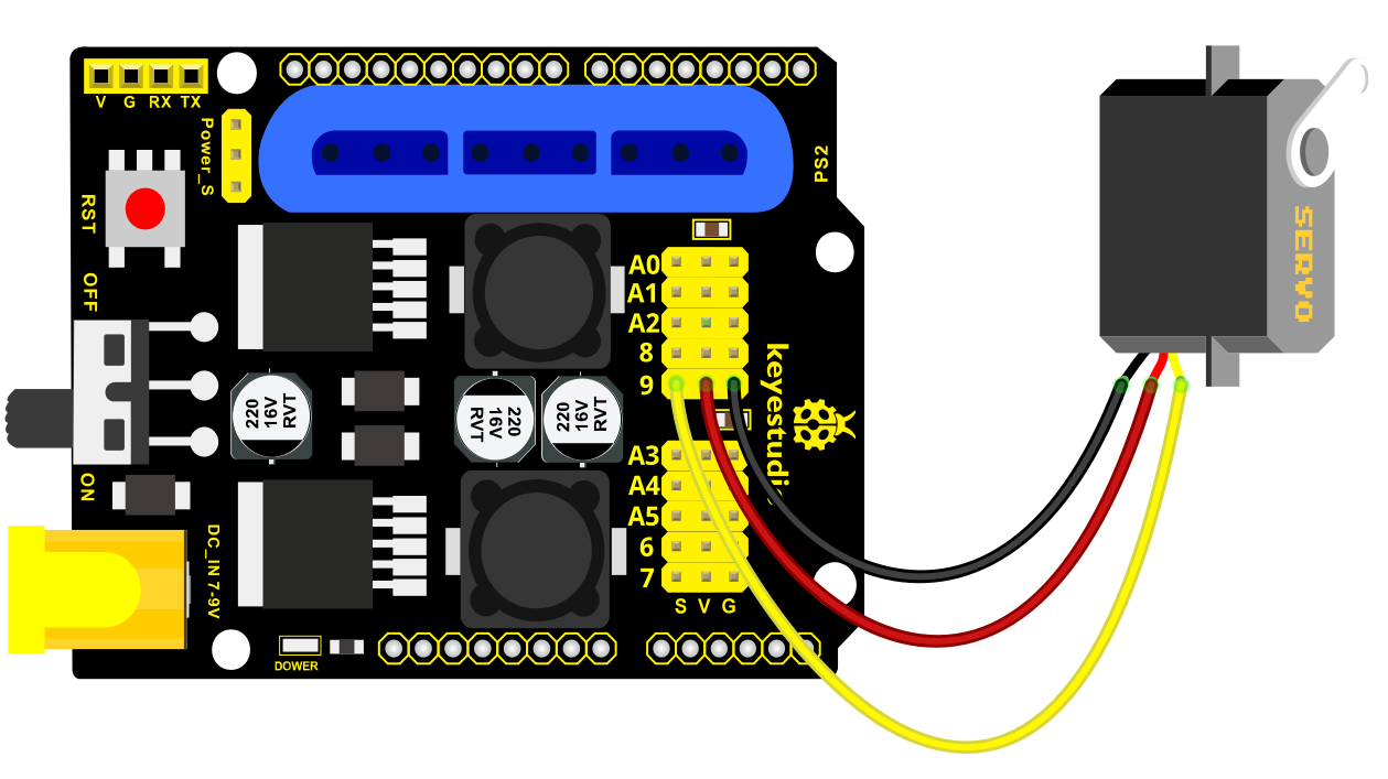
Set the servo to 0°:
#include <Servo.h>
Servo myservo; // create servo object to control a servo
void setup()
{
Serial.begin(9600);
delay(1000);
}
void loop()
{
myservo.attach(9); // Change pin to adjust one by one
myservo.write(0); //Angle
delay(1000);
}
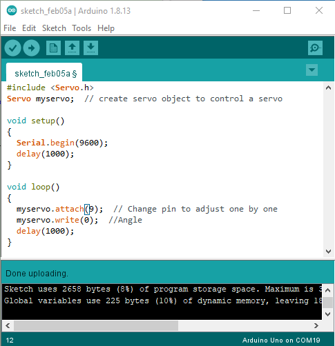
Mount gear wheels:
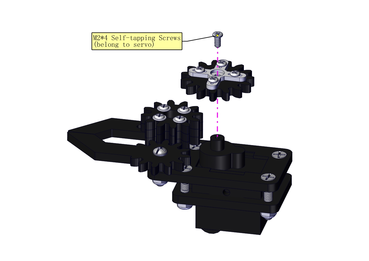
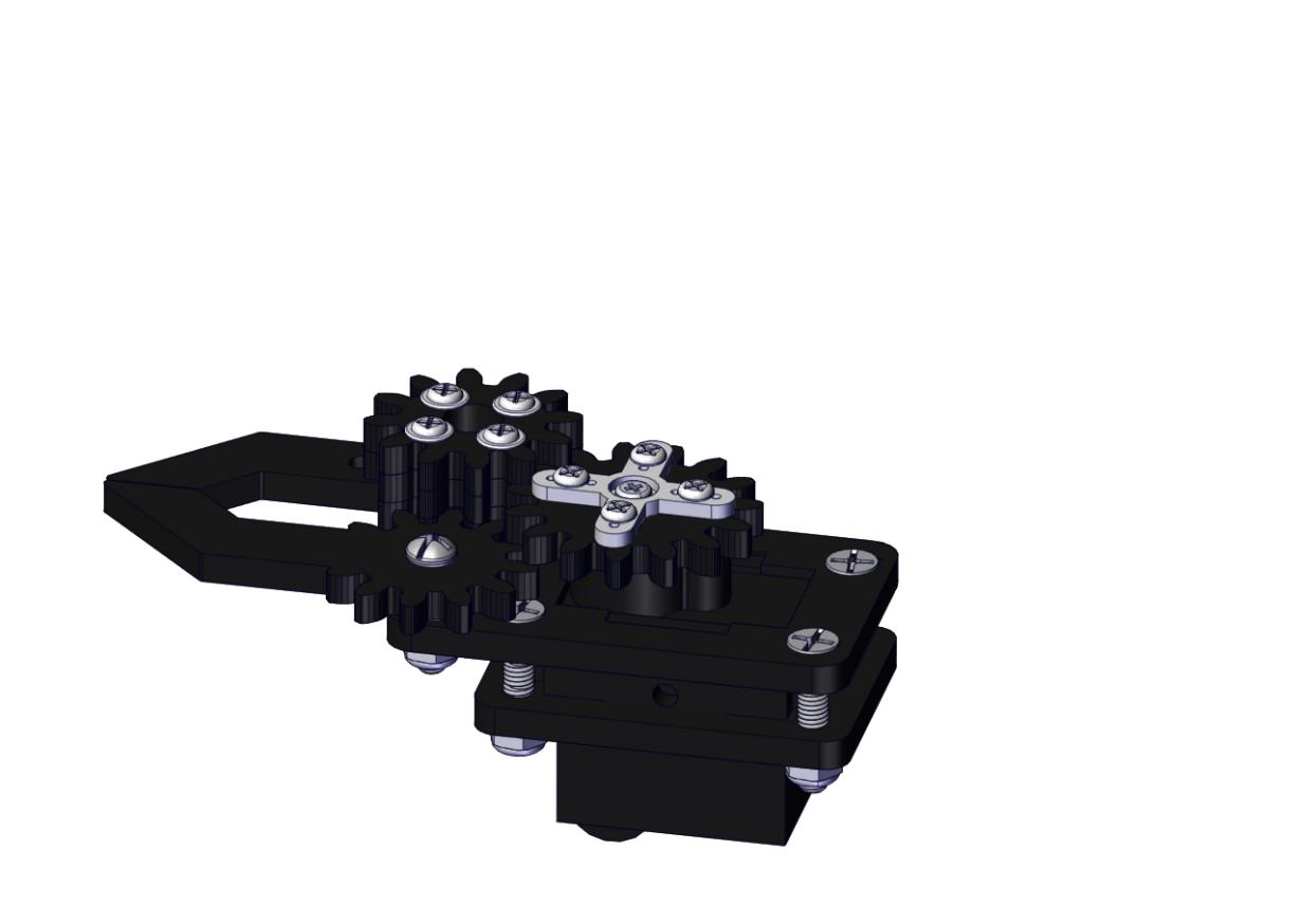
Components Needed:
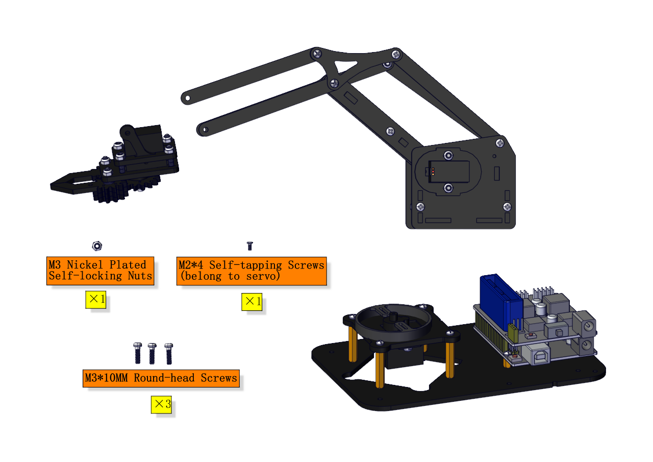
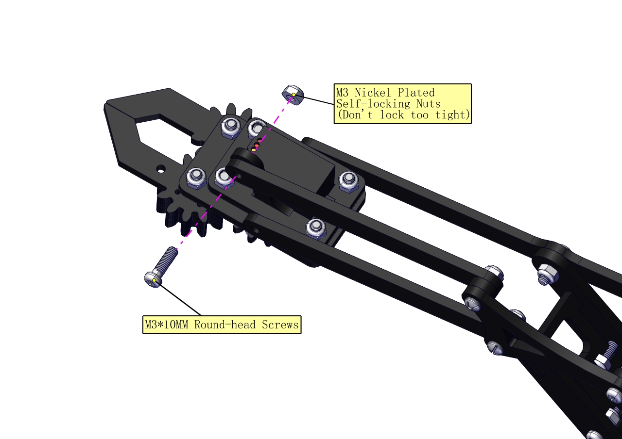
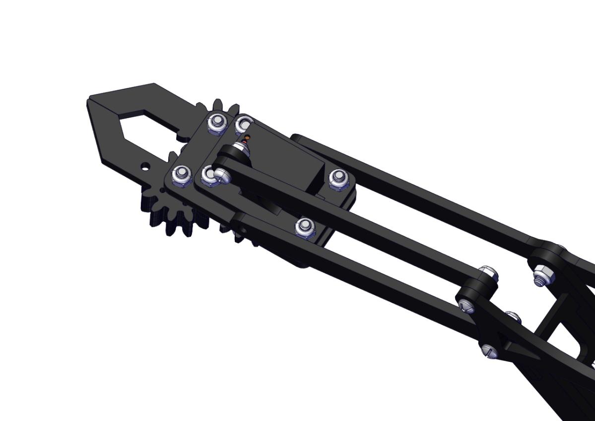
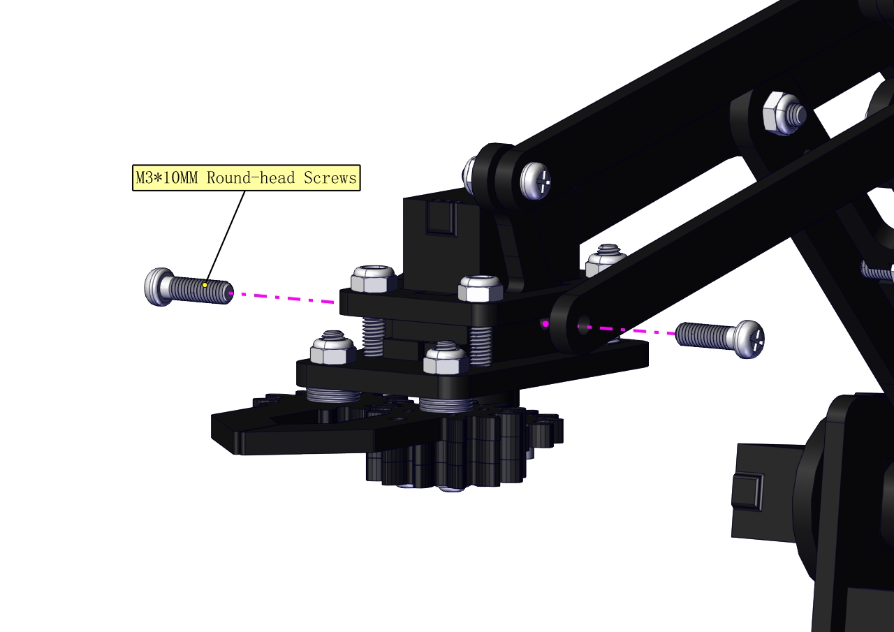
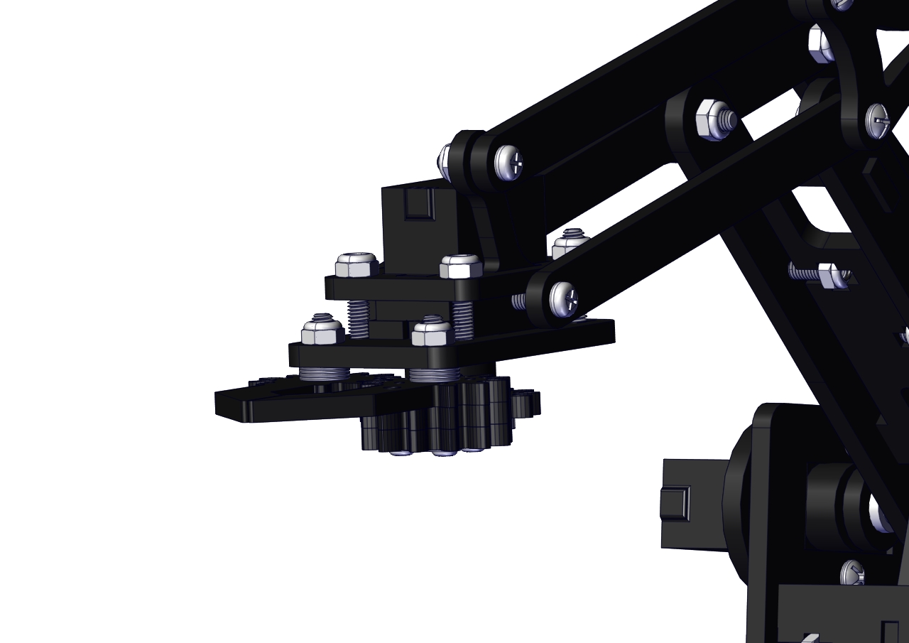
Initialize the servo
Attach this left servo to G, V and S(A1)of sevro motor driver shield, upload the following code, plug in power and press the rest button on the V4.0 board. Then the left servo rotates to 80°
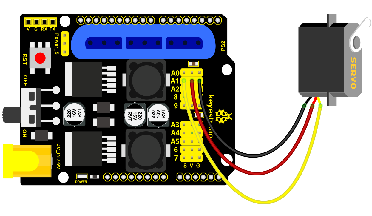
Set the servo to 80°:
#include <Servo.h>
Servo myservo; // create servo object to control a servo
void setup()
{
Serial.begin(9600);
delay(1000);
}
void loop()
{
myservo.attach(A1); // Change pin to adjust one by one
myservo.write(80); //Angle
delay(1000);
}
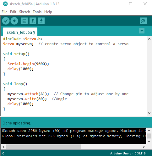
Install the robotic arm:
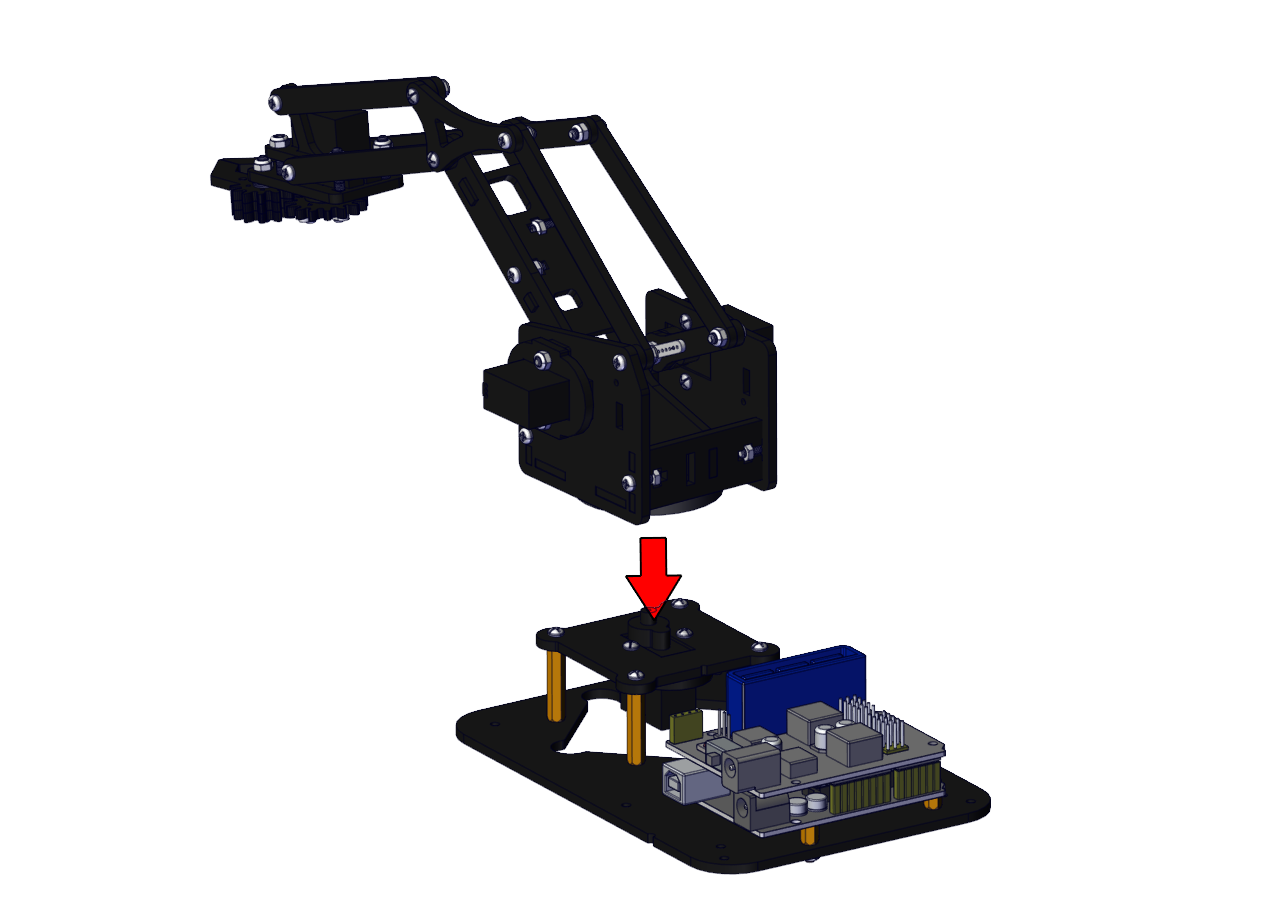
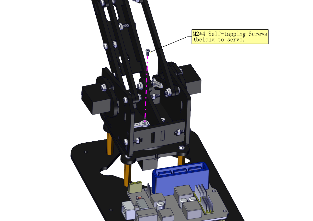
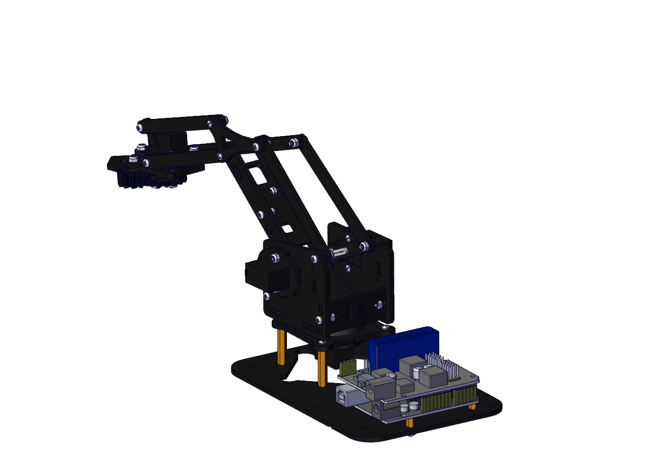
Mount the control part
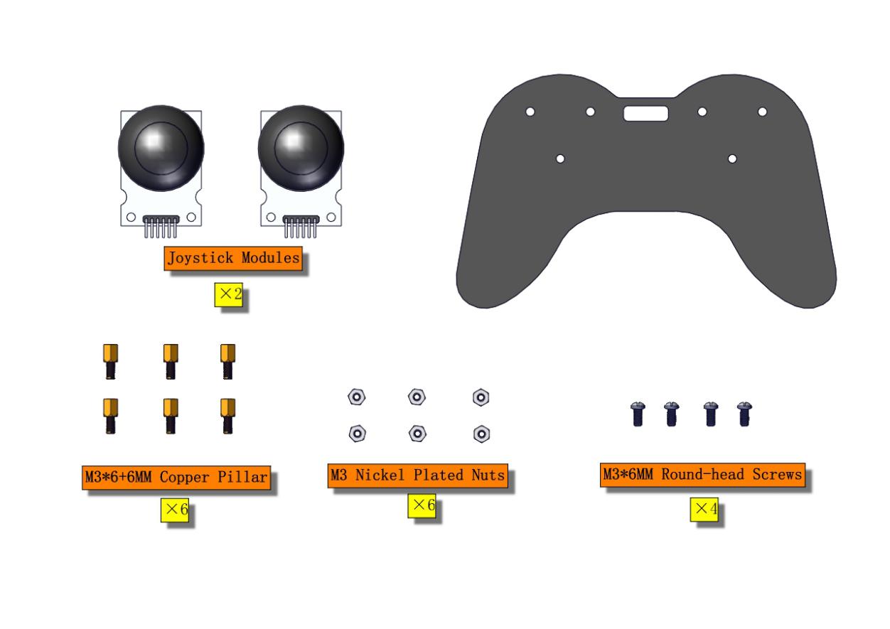
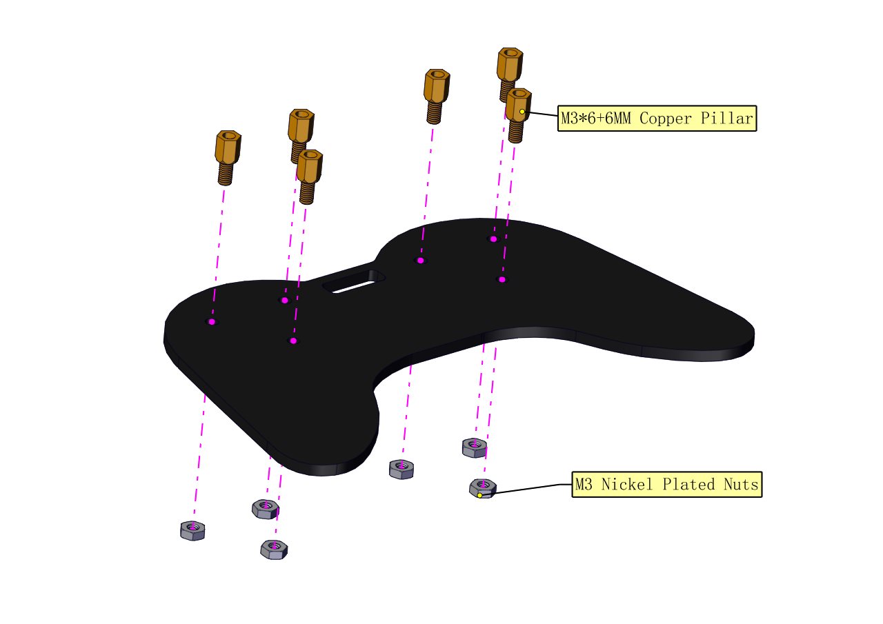
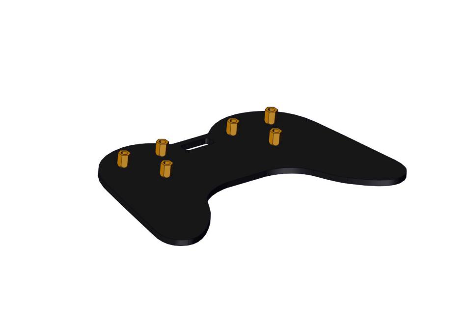
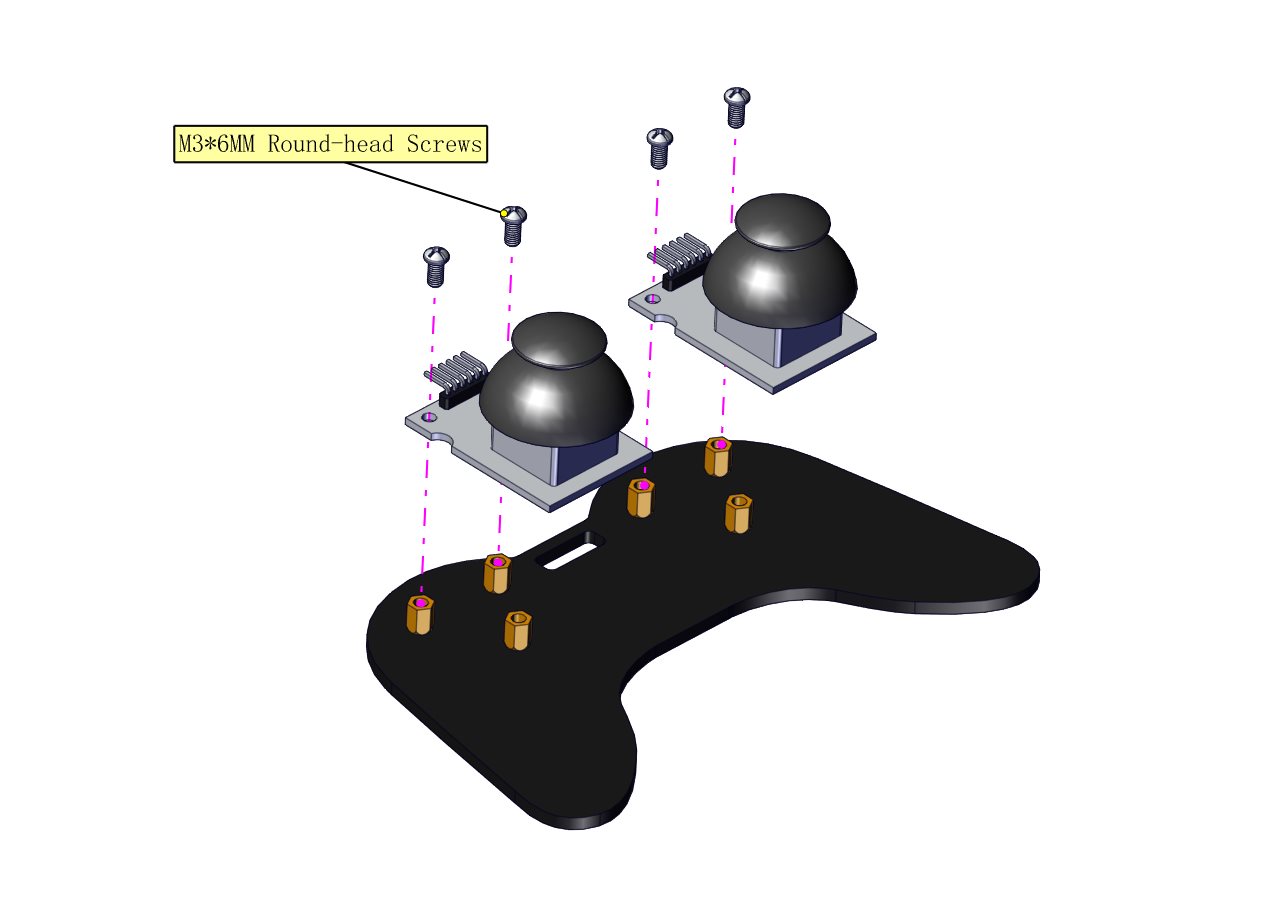
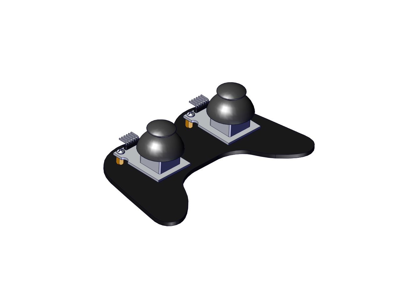
Wiring-up Guide
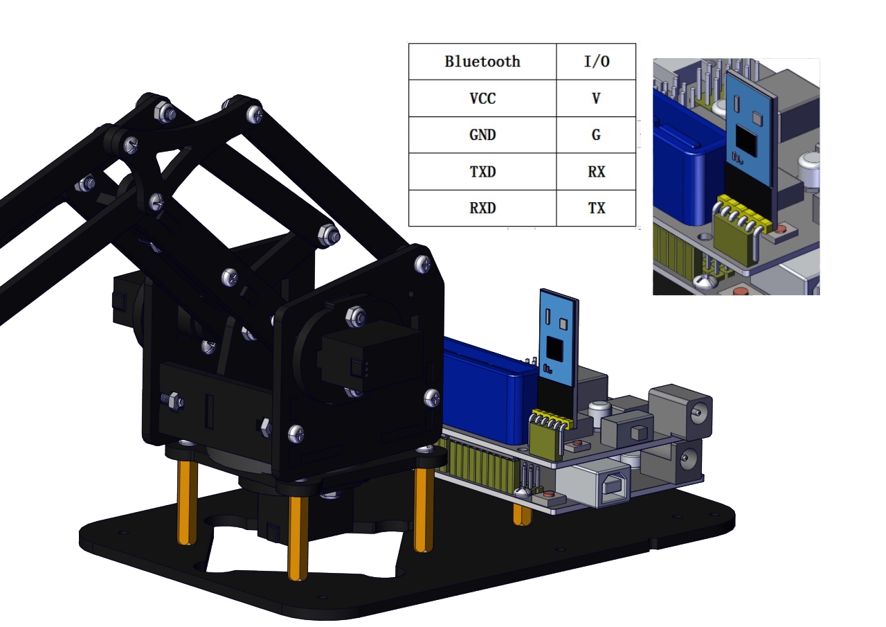
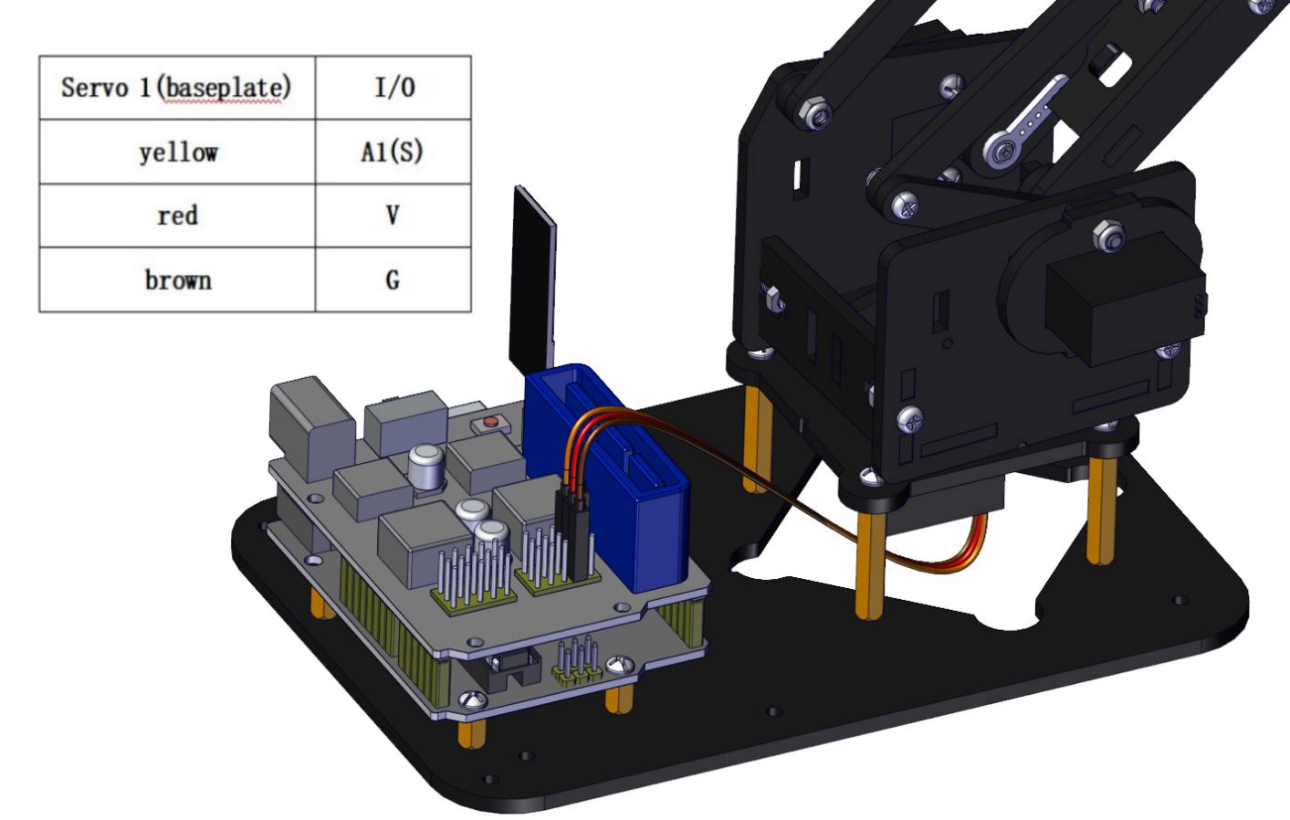
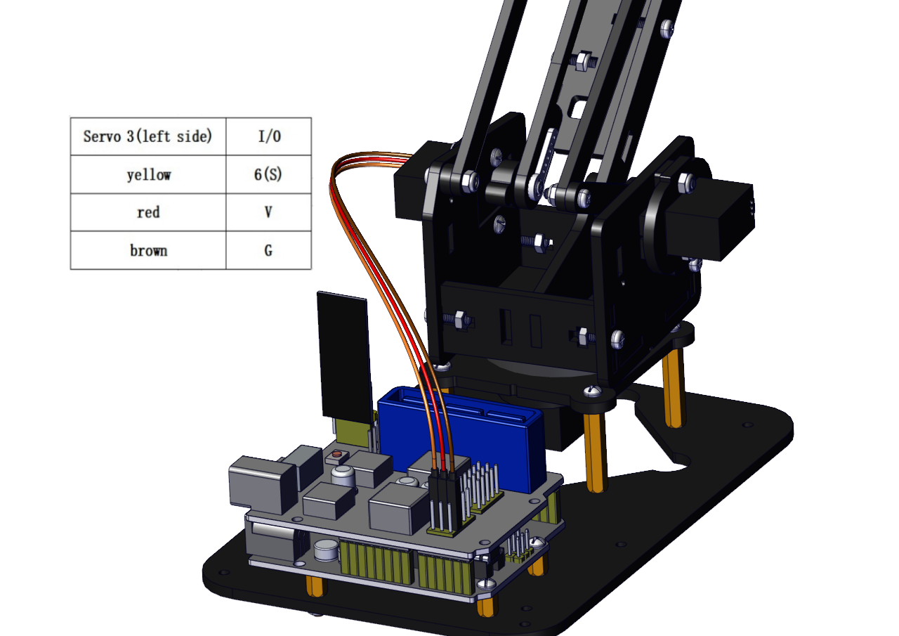
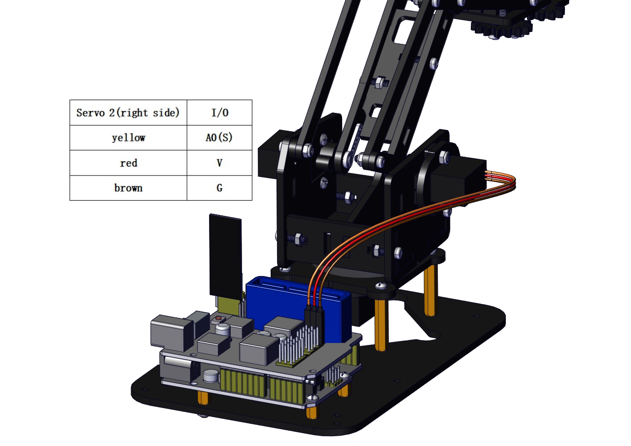
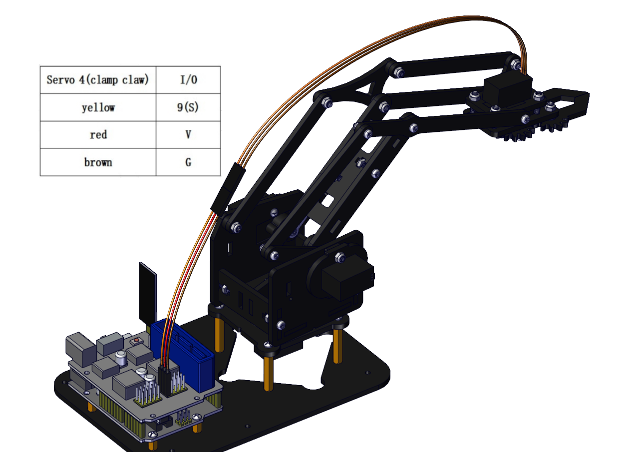
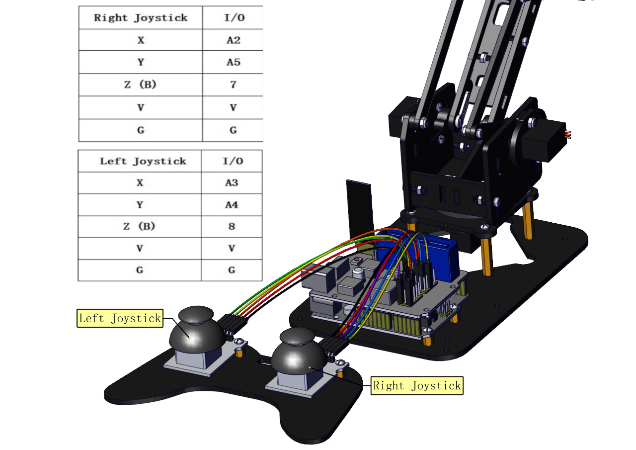
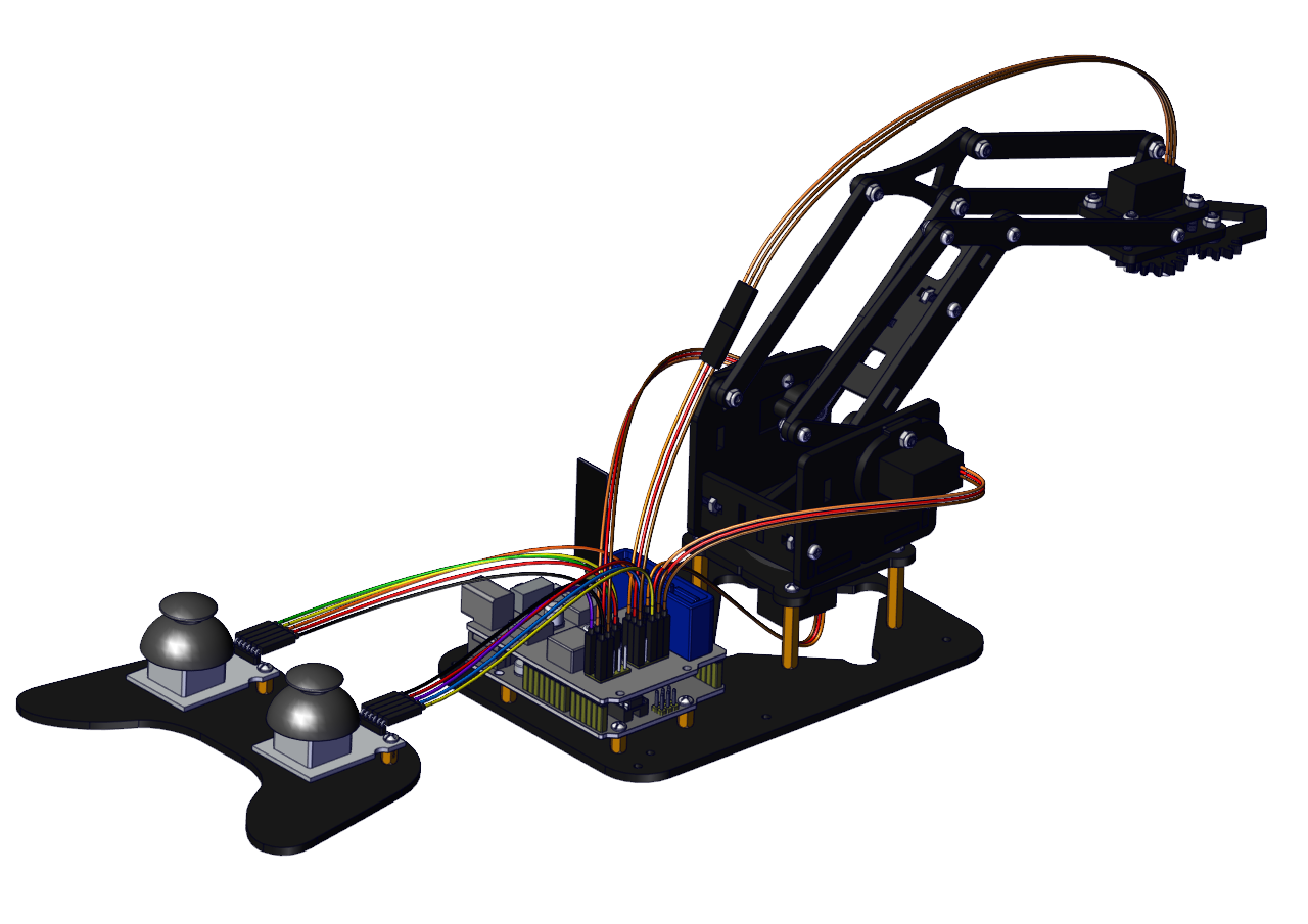
5. Robot Arm Projects
Project 1: Install Arduino IDE and Driver
Keyestudio V4.0 Development Board
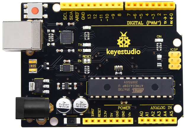
Keyestudio V4.0 development board is an Arduino uno-compatible board, which is based on ATmega328P MCU, and with a cp2102 Chip as a UART-to-USB converter.
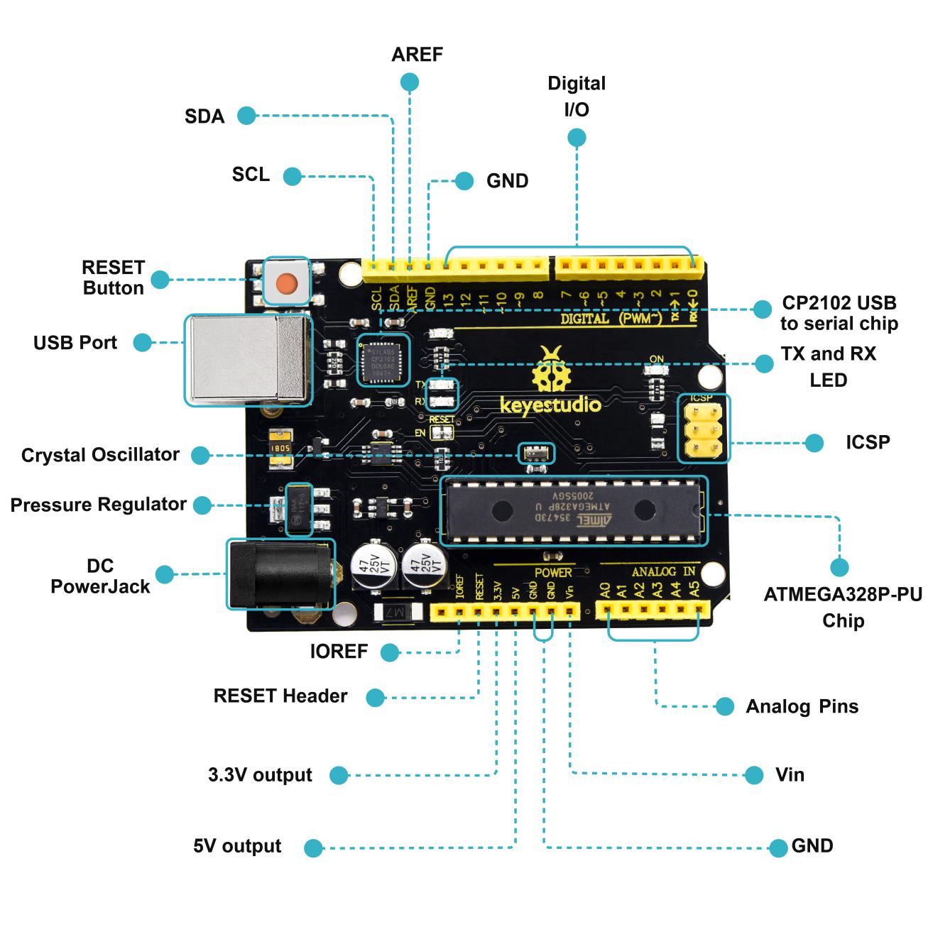
|
1 |
ICSP (In-Circuit Serial Programming) Header |
the AVR, an Arduino micro-program header consisting of MOSI, MISO, SCK, RESET, VCC, and GND. It is often called the SPI (serial peripheral interface) and can be considered an “extension” of the output. In fact, slave the output devices to the SPI bus host. When connecting to PC, program the firmware to ATMEGA328P-PU. |
|---|---|---|
|
2 |
Power LED Indicator |
Powering the Arduino, LED on means that your circuit board is correctly powered on. If LED is off, connection is wrong. |
|
3 |
Digital I/O |
Arduino MEGA has 14 digital input/output pins (of which 6 can be used as PWM outputs).These pins can be configured as digital input pin to read the logic value (0 or 1). Or used as digital output pin to drive different modules like LED, relay, etc. Using pinMode(), digitalWrite(), and digitalRead() functions. |
|
4 |
GND |
GND |
|
5 |
AREF |
Reference voltage (0-5V) for analog inputs. Used with analogReference(). Configures the reference voltage used for analog input (i.e. the value used as the top of the input range). |
|
6 |
SDA |
IIC communication pin |
|
7 |
SCL |
IIC communication pin |
|
8 |
RESET Button |
You can reset your Arduino board, |
|
9 |
D13 LED |
There is a built-in LED driven by digital pin 13. When the pin is HIGH value, the LED is on, when the pin is LOW, it’s off. |
|
10 |
USB Connection |
Arduino board can be powered via USB connector. All you needed to do is connecting the USB port to PC using a USB cable. |
|
11 |
CP2102 |
USB serial chip, translate the USB signal of computer into serial signal |
|
12 |
TX LED |
Onboard you can find the label: TX (transmit) When Arduino board communicates via serial port, send the message, TX led flashes. |
|
13 |
RX LED |
Onboard you can find the label: RX(receive ) When Arduino board communicates via serial port, receive the message, RX led flashes. |
|
14 |
Crystal Oscillator |
How does Arduino calculate time? by using a crystal oscillator. The number printed on the top of the Arduino crystal is 16.000H9H. It tells us that the frequency is 16,000,000 Hertz or 16MHz. |
|
15 |
Voltage Regulator |
To control the voltage provided to the Arduino board, as well as to stabilize the DC voltage used by the processor and other components. Convert an external input DC7-12V voltage into DC 5V, then switch DC 5V to the processor and other components. |
|
16 |
DC Power Jack |
Arduino board can be supplied with an external power DC7-12V from the DC power jack. |
|
17 |
Microcontroller |
Each Arduino board has its own microcontroller. You can regard it as the brain of your board. The main IC (integrated circuit) on the Arduino is slightly different from the panel pair. Microcontrollers are usually from ATMEL. Before you load a new program on the Arduino IDE, you must know what IC is on your board. This information can be checked at the top of IC. |
|
18 |
IOREF |
This pin on the board provides the voltage reference with which the microcontroller operates. A properly configured shield can read the IOREF pin voltage and select the appropriate power source or enable voltage translators on the outputs for working with the 5V or 3.3V. |
|
19 |
RESET Header |
Connect an external button to reset the board. The function is the same as reset button. |
|
20 |
Power Pin 3V3 |
A 3.3 volt supply generated by the on-board regulator. Maximum current draw is 50 mA. |
|
21 |
Power Pin 5V |
Provides 5V output voltage |
|
22 |
Vin |
You can supply an external power input DC7-12V through this pin to Arduino board. |
|
23 |
Analog Pins |
Onboard has 6 analog inputs, labeled A0 to A5. |
(1)Installing Arduino IDE
When we get control board, we need to download Arduino IDE and driver firstly.
You could download Arduino IDE from the official website:
https://www.arduino.cc/, click the SOFTWARE on the browse bar, click “DOWNLOADS” to enter download page, as shown below:


There are two versions of IDE for WINDOWS system, you can choose between the Installer (.exe) and the Zip packages. We suggest you use the first one that installs directly everything you need to use the Arduino Software (IDE), including the drivers. With the Zip package you need to install the drivers manually. The Zip file is also useful if you want to create a portable installation.
(2) Installing Driver of V4.0 Board
Let’s install the driver of keyestudio V4.0 board. The USB-TTL chip on V4.0 board adopts CP2102 serial chip. The driver program of this chip is included in Arduino 1.8 version and above, which is convenient. Plugging on USB port of board, the computer can recognize the hardware and automatically install the driver of CP2102.
If the version of your Arduino is not above 1.8 version, you can download the driver of CP2102:
https://www.silabs.com/products/development-tools/software/usb-to-uart-bridge-vcp-drivers
If you install it unsuccessfully, please open the device manager of computer.
Right click Computer—– Properties—– Device Manager

The yellow exclamation mark on the page implies an unsuccessful installation and you should double click the hardware and update the driver.

Click“OK”to enter the following page. Click“browse my computer for updated driver software”

Click “Browse”, then search the driver of CP2102 and click “Next”,There is a DRIVERS folder in Arduino software installed package( ), open driver folder and check the driver of CP210X series chips.

When opening the device manager, we will find the yellow exclamation mark disappear. The driver of CP2102 is installed successfully.


(3)Arduino IDE Setting
Click icon,and open Arduino IDE.

When downloading the sketch to the board, you must select the correct name of Arduino board that matches the board connected to your computer. As shown below;

Then select the correct COM port (you can see the corresponding COM port after the driver is successfully installed)


-
A- Used to verify whether there is any compiling mistakes or not.
-
B- Used to upload the sketch to your Arduino board.
-
C- Used to create shortcut window of a new sketch.
-
D- Used to directly open an example sketch.
-
E- Used to save the sketch.
-
F- Used to send the serial data received from board to the serial monitor.
|
Name |
0° |
180° |
|---|---|---|
|
Servo 1(baseplate) |
Rotate toward the rightmost |
Rotate toward the leftmost |
|
Servo 2 (right side) |
Rocker arm connected to Servo 2 draws back |
stretch out |
|
Servo 3 (left side) |
Rocker arm connected to Servo 3 stretches out |
draw back |
|
Servo 4 (clamp claw) |
close |
open |
Project 2: 4DOF Rotation and Pin Control
(1)Joint Rotation and Servo Angle Settings
(2)Pin Control
|
Name |
IO Pin |
|---|---|
|
Servo 1 (baseplate) |
A1 |
|
Servo 2 (right side) |
A0 |
|
Servo 3 (left side) |
6 |
|
Servo 4 (clamp claw) |
9 |
|
Right Joystick X |
A2 |
|
Right Joystick Y |
A5 |
|
Right Joystick Z (B) |
7 |
|
Left Joystick X |
A3 |
|
Left Joystick Y |
A4 |
|
Left Joystick Z(B) |
8 |
|
D1/DAT of PS2 |
12 |
|
D0/CMD of PS2 |
11 |
|
CE/SEL of PS2 |
10 |
|
CLK of PS2 |
13 |
Project 3: Control the Robot Arm by Joysticks
3.1 Servo Control
Description
In the previous projects, we set the square wave and angles of servos.
Now, we use libraries of servos to control the angle of a servo. We only need to put the servo folder in the libraries folder where the Arduino IDE location is installed, then open the Arduino IDE, the library file will take effect.
Connection Diagram
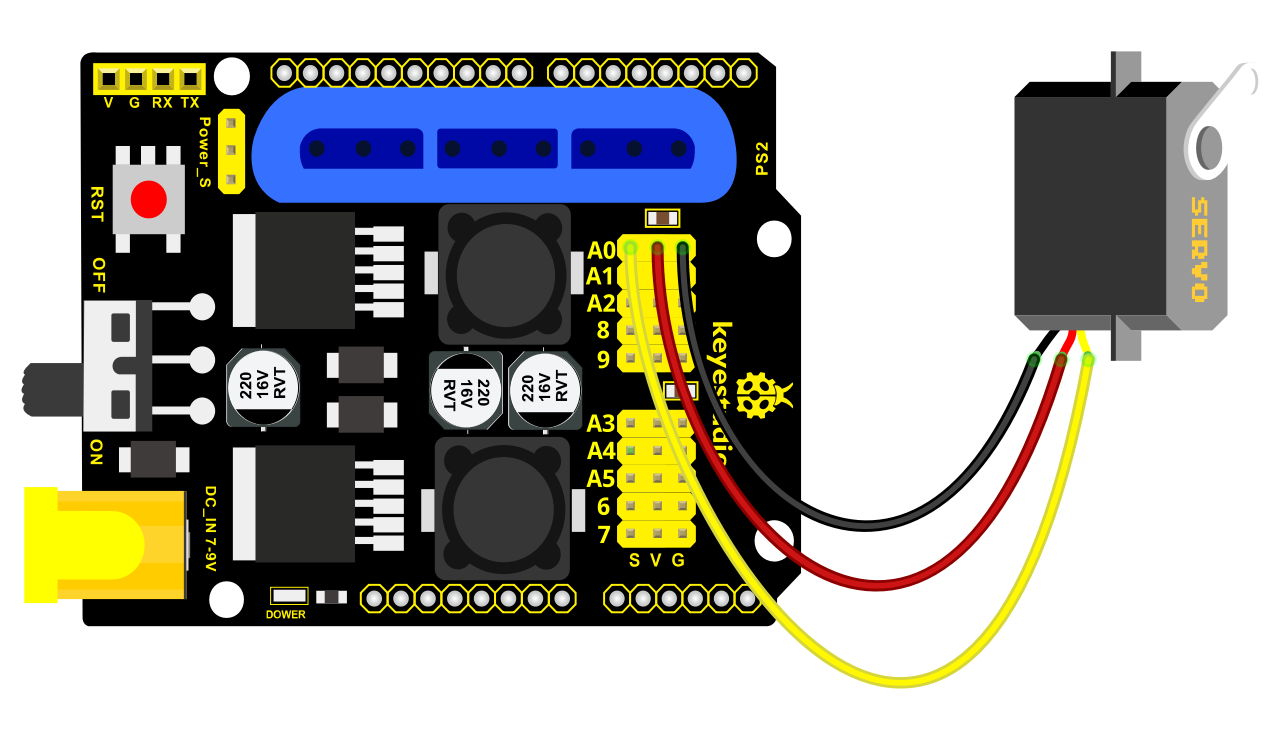
Test Code 1:
 #include  <Servo.h >
Servo myservo; // create servo object to control a servo
void setup()
{
Serial.begin(9600);
delay(1000);
}
void loop()
{
myservo.attach(A0); // modify each pin to adjust
myservo.write(0); // angle value
delay(1000);
}
Test Result:
Stack the drive shield onto V4.0 board and connect the servo motor, upload the code, plug in power and press the reset button. Then the servo will automatically rotate to 0°.
Automatic Movement
Description:
In the previous section, you have learned to set the servo angle. In fact, we just need to continually change angles of 4 servo, thus make the 4DOF robot arm operate different motions.
Hookup Guide:
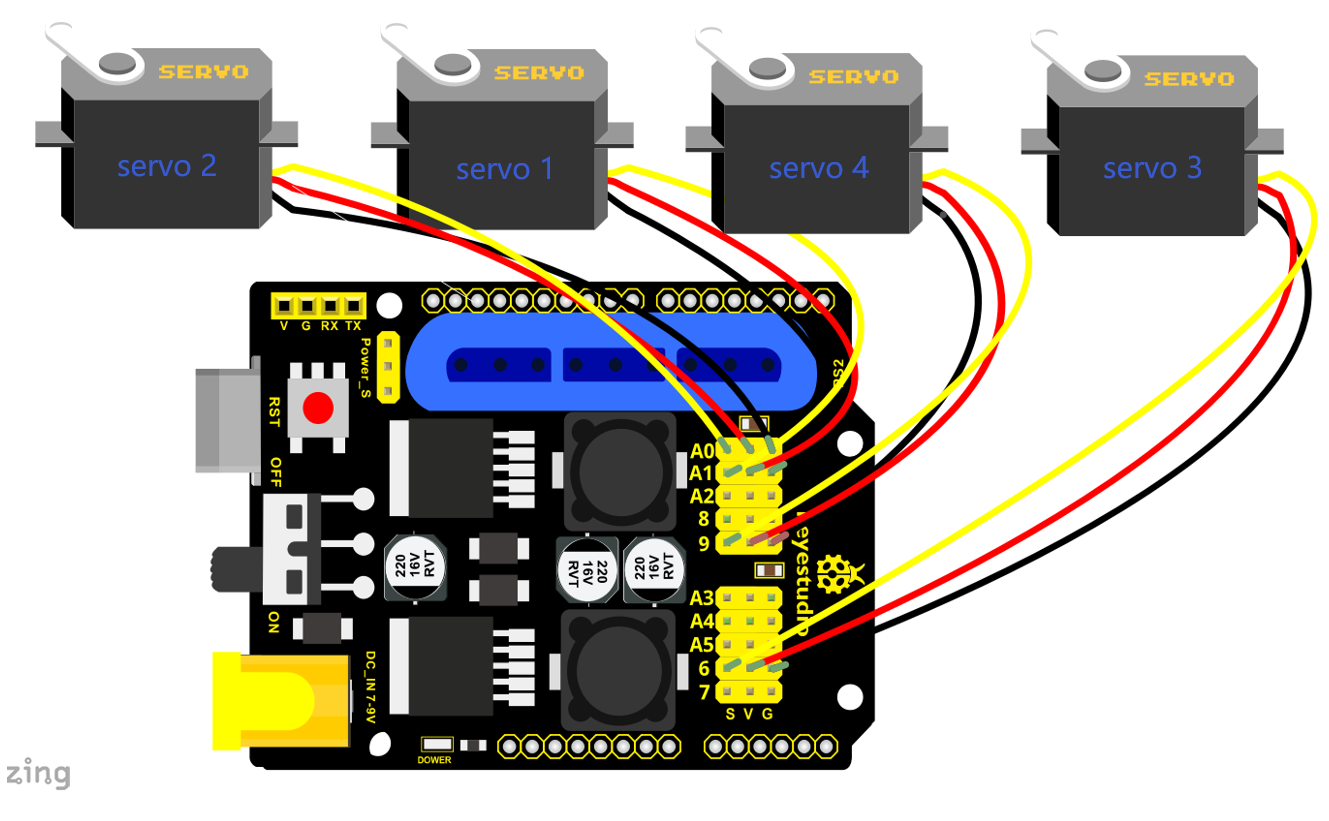
Test Code 2:
 #include  <Servo.h >
Servo myservo1; // create servo object to control a servo
Servo myservo2;
Servo myservo3;
Servo myservo4;
int pos1=80, pos2=60, pos3=130, pos4=0;
void setup()
{
myservo1.attach(A1); // attaches the servo on pin 9 to the servo object
myservo2.attach(A0);
myservo3.attach(6);
myservo4.attach(9);
myservo1.write(pos1);
delay(1000);
myservo2.write(pos2);
myservo3.write(pos3);
myservo4.write(pos4);
delay(1500);
}
void loop()
{
// turn right
for(pos1;pos1 >0;pos1--)
{
myservo1.write(pos1);
delay(5); // delay 5ms(used to adjust the servo speed)
}
delay(1000);
// open the claw
for(pos4;pos4 <100;pos4++)
{
myservo4.write(pos4);
}
delay(1000);
// right servo rotates to 100 degrees
for(pos2;pos2 >50;pos2--)
{
myservo2.write(pos2);
delay(5);
}
// left servo rotates to 5 degrees
for(pos3;pos3 >50;pos3--)
{
myservo3.write(pos3);
delay(5);
}
delay(1500);
// close the claw
for(pos4;pos4 >0;pos4--)
{
myservo4.write(pos4);
}
delay(1000);
// left servo rotates to100 degrees, rocker arm lifts.
for(pos3;pos3 <120;pos3++)
{
myservo3.write(pos3);
delay(5);
}
delay(1000);
// turn to left
for(pos1;pos1 <180;pos1++)
{
myservo1.write(pos1);
delay(5);
}
delay(1000);
// Lower the arm
for(pos3;pos3 >50;pos3--)
{
myservo3.write(pos3);
delay(5);
}
delay(1000);
// open the claw
for(pos4;pos4 <100;pos4++)
{
myservo4.write(pos4);
}
delay(1000);
// lift up the arm
for(pos3;pos3 <120;pos3++)
{
myservo3.write(pos3);
delay(5);
}
delay(1000);
// close the claw
for(pos4;pos4 >0;pos4--)
{
myservo4.write(pos4);
}
delay(1000);
}
Test Result:
Stack the driver shield onto V4.0 board and connect the servo motor, upload well the code., plug in power and press the reset button. Then the robot arm will rotate to right, stretch out the arm, lower and enable claw; then it will withdraw, lift, rotate to left, stretch out, lower and make claw open.
This series of actions will be continuous.
3.2 Read the Joystick Value
Description:
The sensor’s pin X, Y are for analog sensor, so directly read the measured analog value. Pin Z is a digital button, first should set the pin to Input status and then read the measured value 1 (pressed down) or 0 (not press). Check out the value printed on the serial monitor.
Connection Diagram:
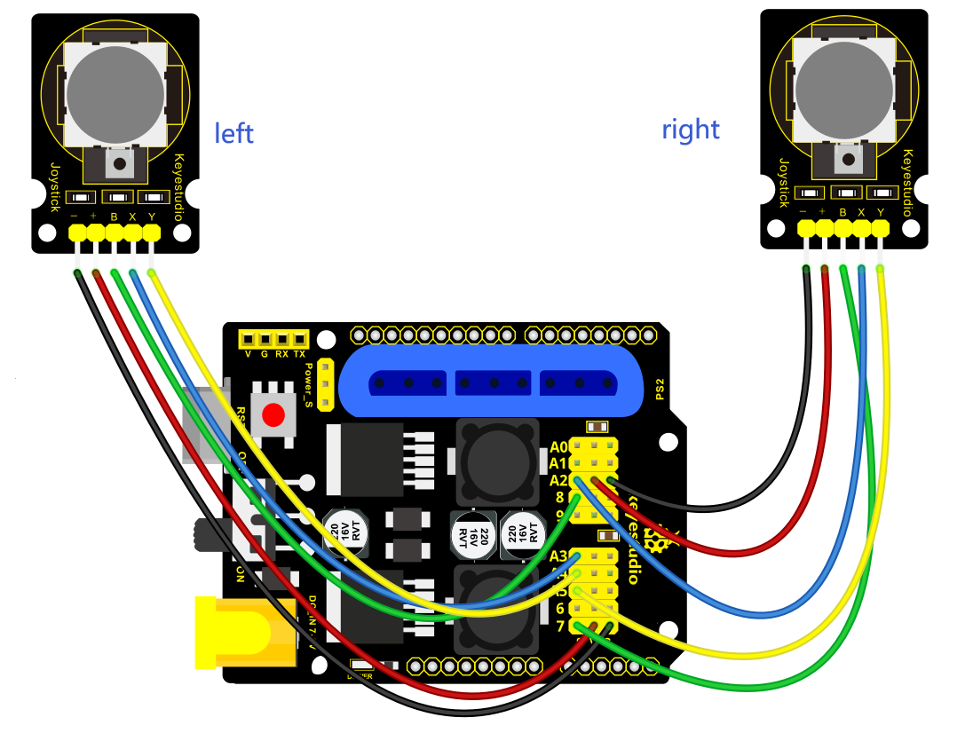
Test Code 3:
const int right_X = A2; // define the right X pin to A2
const int right_Y = A5; // define the right Y pin to A5
const int right_key = 7; //define the right key pin to 7(that is the value Z)
const int left_X = A3; //define the left X pin to A3
const int left_Y = A4; // define the left Y pin to A4
const int left_key = 8; //define the left key pin to 8(that is the value Z)
void setup()
{
pinMode(right_key, INPUT); // set the right/left key to INPUT
pinMode(left_key, INPUT);
Serial.begin(9600); // set the baud rate to 9600
}
void loop()
{
int x1,y1,z1; // define the variable, used to save the joystick value it reads
int x2,y2,z2;
x1 = analogRead(right_X); // read the value of right X
y1 = analogRead(right_Y); // read the value of right Y
z1 = digitalRead(right_key); //// read the value of right Z
x2 = analogRead(left_X); // read the value of left X
y2 = analogRead(left_Y); // read the value of left Y
z2 = digitalRead(left_key); // read the value of left Z
Serial.print("right_X = "); // on the serial monitor, print out right_X =
Serial.println(x1 ,DEC); // print out the value of right X and line wrap
Serial.print("right_Y = ");
Serial.println(y1 ,DEC);
//Serial.print("right_key = ");
//Serial.println(z1 ,DEC);
// Serial.println("**********right**********");
/*Serial.print("left_X = ");
Serial.println(x2 ,DEC);
Serial.print("left_Y = ");
Serial.println(y2 ,DEC);
Serial.print("left_key = ");
Serial.println(z2 ,DEC);
Serial.println("*********left***********");*/
delay(200);
}
Test Result:
Hook it up and upload well the code. Connect the V4.0 to computer using a USB cable, then open the serial monitor and set the baud rate to 9600, you should see the analog value of the right Joystick pin X,Y.
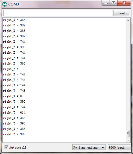
3.3 Dual-Joystick Control
Description:
In the previous section, we have introduced how to use 4 Servo to control the robot arm. Next, combine those two experiments. Use two Joystick modules to control 4DOF robot arm realize different motions.
At first, set the boot posture. The Joystick control is shown as below table.
|
Right Joystick |
Servo |
Left Joystick |
Servo |
|---|---|---|---|
|
X1 <50 |
Servo 1 gradually reduces to 0° (push the right joystick to the right, the servo that controls the arm rotation turns right, and stops at 0° ) |
X2 <50 |
Servo 4 gradually reduces to 0° (push the left joystick to the right, the claw is closed) |
|
X1 >1000 |
Servo 1 gradually increases to 180° (push the right joystick to the left, the servo that controls the arm rotation turns left, and stops at 180° ) |
X2 >1000 |
Servo 4 gradually increases to 180° (push the left joystick to the left, the claw opens) |
|
Y1 >1000 |
Servo 2 gradually reduces to 0° ( that is, lift up the robot upper arm) |
Y2 >1000 |
Servo 3 gradually reduces to 35° ( that is, stretch out the robot lower arm) |
|
Y1 <50 |
Servo 2 gradually reduces to 180° ( that is, lower the robot upper arm) |
Y2 <50 |
Servo 3 gradually increases to 180° ( that is, draw back the robot lower arm) |
Hookup Guide:
Test Code 4:
  #include   <Servo.h  > // add the servo libraries
Servo myservo1; // create servo object to control a servo
Servo myservo2;
Servo myservo3;
Servo myservo4;
int pos1=80, pos2=60, pos3=130, pos4=0; // define the variable of 4 servo
angle,and assign the initial value (that is the boot posture angle value)
const int right_X = A2; // define the right X pin to A2
const int right_Y = A5; // define the right Y pin to A5
const int right_key = 7; // define the right key pin to 7(that is the value of
Z)
const int left_X = A3; // define the left X pin to A3
const int left_Y = A4; // define the left X pin to A4
const int left_key = 8; //define the left key pin to 8(that is the value of Z)
int x1,y1,z1; // define the variable, used to save the joystick value it read.
int x2,y2,z2;
void setup()
{
// boot posture
myservo1.write(pos1);
delay(1000);
myservo2.write(pos2);
myservo3.write(pos3);
myservo4.write(pos4);
delay(1500);
pinMode(right_key, INPUT); // set the right/left key to INPUT
pinMode(left_key, INPUT);
Serial.begin(9600); // set the baud rate to 9600
}
void loop()
{
myservo1.attach(A1); // set the control pin of servo 1 to A1
myservo2.attach(A0); // set the control pin of servo 2 to A0
myservo3.attach(6); //set the control pin of servo 3 to D6
myservo4.attach(9); // set the control pin of servo 4 to D9
x1 = analogRead(right_X); //read the right X value
y1 = analogRead(right_Y); // read the right Y value
z1 = digitalRead(right_key); //// read the right Z value
x2 = analogRead(left_X); //read the left X value
y2 = analogRead(left_Y); //read the left Y value
z2 = digitalRead(left_key); // read the left Z value
//delay(5); // lower the speed overall
// claw
zhuazi();
// rotate
zhuandong();
// upper arm
xiaobi();
//lower arm
dabi();
}
//claw
void zhuazi()
{
//claw
if(x2  <50) // if push the left joystick to the right
{
pos4=pos4-2; //current angle of servo 4 subtracts 2(change the value you
subtract, thus change the closed speed of claw)
//Serial.println(pos4);
myservo4.write(pos4); // servo 4 operates the action, claw is gradually closed.
delay(5);
if(pos4  <2) // if pos4 value subtracts to 2, the claw in 37 degrees we have
tested is closed.
{ //(should change the value based on the fact)
pos4=2; // stop subtraction when reduce to 2
}
}
if(x2  >1000) //// if push the left joystick to the left
{
pos4=pos4+8; // current angle of servo 4 plus 8(change the value you plus, thus
change the open speed of claw)
//Serial.println(pos4);
myservo4.write(pos4); // servo 4 operates the motion, the claw gradually opens.
delay(5);
if(pos4  >108) // limit the largest angle when open the claw
{
pos4=108;
}
}
}
//*********************************  *  *  *******************
// turn
void zhuandong()
{
if(x1  <50) // if push the right joystick to the right
{
pos1=pos1-1; //pos1 subtracts 1
myservo1.write(pos1); // servo 1 operates the motion, the arm turns right.
delay(5);
if(pos1  <1) // limit the angle when turn right
{
pos1=1;
}
}
if(x1  >1000) // if push the right joystick to the let
{
pos1=pos1+1; //pos1 plus 1
myservo1.write(pos1); // arm turns left
delay(5);
if(pos1  >180) // limit the angle when turn left
{
pos1=180;
}
}
}
//  *  *  *  *  *  *  *  *  *  *  *  *  *  *  *  *  *  *  *  *  *  *  *  *  *  *  *  *  *  *  *  *  *  *  *  *  *  *  *  *  *  *  *  *  *  *  *  *  *  *  *  *  *  *  *  *  **/
//upper arm
void xiaobi()
{
if(y1>1000) // if push the right joystick upward
{
pos2=pos2-1;
myservo2.write(pos2); // the upper arm will lift
delay(5);
if(pos2  <0) // limit the lifting angle
{
pos2=0;
}
}
if(y1  <50) // if push the right joystick downward
{
pos2=pos2+1;
myservo2.write(pos2); // upper arm will go down
delay(5);
if(pos2  >180) // limit the angle when go down
{
pos2=180;
}
}
}
// lower arm
void dabi()
{
if(y2<50) // if push the left joystick upward
{
pos3=pos3+1;
myservo3.write(pos3); // lower arm will stretch out
delay(5);
if(pos3  >180) // limit the stretched angle
{
pos3=180;
}
}
if(y2  >1000) // if push the left joystick downward
{
pos3=pos3-1;
myservo3.write(pos3); // lower arm will draw back
delay(5);
if(pos3  <35) // limit the retracted angle
{
pos3=35;
}
}
}
Test Result:
Upload the code to main board and stack the shield onto it and wire them up, then 4DOF robot arm will keep the initial position. You can control the robot arm with Joysticks
3.4 Add Memory Function
Memorize One Posture
Description:
In the previous section, use the analog value of pin X,Y of 2 Joystick modules to control the robot arm.
In the following experiment, we add a memory function for the robot arm, making it remember a posture then operate. Set 4 variables for saving the angle value of 4 servos, use the Joystick to control a posture. Press the key Z1 of right Joystick to save the angle value of 4 servos; press the key Z2 of left Joystick to make the servo operate a posture saved in the variable.
Connection Diagram
Test Code 5:
  #include   <Servo.h  > // add servo libraries
Servo myservo1; // create servo object to control a servo
Servo myservo2;
Servo myservo3;
Servo myservo4;
int pos1=80, pos2=60, pos3=130, pos4=0; // define the variable of 4 servo angle
and assign the initial value( that is the boot posture angle value)
const int right_X = A2; // define the right X pin to A2
const int right_Y = A5; // define the right Y pin to A3
const int right_key = 7; // define the right key pin to 7(that is Z value)
const int left_X = A3; // define the left X pin to A3
const int left_Y = A4; // define the left Y pin to A4
const int left_key = 8; // define the left key pin to 8(that is Z value)
int x1,y1,z1; // define the variable, used to save the joystick value.
int x2,y2,z2;
int s1,s2,s3,s4;
void setup()
{
// boot posture
myservo1.write(pos1);
delay(1000);
myservo2.write(pos2);
myservo3.write(pos3);
myservo4.write(pos4);
delay(1500);
pinMode(right_key, INPUT); // set the right/left key to INPUT
pinMode(left_key, INPUT);
Serial.begin(9600); // set the baud rate to 9600
}
void loop()
{
myservo1.attach(A1); // set the control pin of servo 1 to A1
myservo2.attach(A0); // set the control pin of servo 2 to A0
myservo3.attach(6); //set the control pin of servo 3 to D6
myservo4.attach(9); //set the control pin of servo 4 to D9
x1 = analogRead(right_X); // read the right X value
y1 = analogRead(right_Y); // read the right Y value
z1 = digitalRead(right_key); //// read the right key Z value
x2 = analogRead(left_X); // read the left X value
y2 = analogRead(left_Y); //read the left Y value
z2 = digitalRead(left_key); //read the left key Z value
//delay(5); // reduce the speed overall
if(z1==1) // if the right joystick key is pressed
{
delay(10); // delay for eliminating shake
if(z1==1) // judge again if the right key is pressed
{
s1=myservo1.read(); // read the angle value of each servo
s2=myservo2.read();
s3=myservo3.read();
s4=myservo4.read();
}
}
if(z2==1) // if the left key is pressed
{
delay(10);
if(z2==1)
{
pos1=myservo1.read(); // record the angle value of 4 servos in current posture
pos2=myservo2.read();
pos3=myservo3.read();
pos4=myservo4.read();
if(pos1  <s1) // if angle of servo 1 is smaller than variable s1 value
{
while(pos1  <s1) //while loop,rotate the servo to the position of the value
stored in the array.
{
myservo1.write(pos1); // servo 1 operates the motion
pos1++; //pos1 plus 1
delay(5); // delay for 5ms,controlling the rotation speed of servo.
}
}
else // if angle of servo 1 is greater than the value stored in array 1.
{
while(pos1  >s1) //while loop,rotate the servo to the position of the value
stored in the array.
{
myservo1.write(pos1); // servo 1 operates the motion
pos1--; //pos1 subtracts 1
delay(5); // delay for 5ms,controlling the rotation speed of servo.
}
}
// the explanation is the same as servo 1
if(pos2<s2)
{
while(pos2<s2)
{
myservo2.write(pos2);
pos2++;
delay(5);
}
}
else
{
while(pos2>s2)
{
myservo2.write(pos2);
pos2--;
delay(5);
}
}
//*************************************************
// the explanation is the same as servo 1
if(pos3<s3)
{
while(pos3<s3)
{
myservo3.write(pos3);
pos3++;
delay(5);
}
}
else
{
while(pos3>s3)
{
myservo3.write(pos3);
pos3--;
delay(5);
}
}
//*************************************************
// the explanation is the same as servo 1
if(pos4<s4)
{
while(pos4<s4)
{
myservo4.write(pos4);
pos4++;
delay(5);
}
}
else
{
while(pos4>s4)
{
myservo4.write(pos4);
pos4--;
delay(5);
}
}
}
}
//claw
zhuazi();
//turn
zhuandong();
// upper arm
xiaobi();
// lower arm
dabi();
}
//claw
void zhuazi()
{
//claw
if(x2  <50) // if push the left joystick to the right
{
pos4=pos4-2; // current angle of servo 4 subtracts 2(change the value you
subtract, thus change the closed speed of claw)
//Serial.println(pos4);
myservo4.write(pos4); //servo 4 operates the action, claw is gradually closed
delay(5);
if(pos4  <2) // if pos4 value subtracts to 2, the claw in 37 degrees we have
tested is closed.)
{ //(should change the value based on the fact)
pos4=2; // stop subtraction when reduce to 2
}
}
if(x2  >1000) //// if push the left joystick to the left
{
pos4=pos4+8; // current angle of servo 4 plus 8(change the value you plus, thus
change the open speed of claw)
//Serial.println(pos4);
myservo4.write(pos4); // servo 4 operates the motion, the claw gradually opens.
delay(5);
if(pos4  >90) // limit the largest angle when open
{
pos4=90;
}
}
}
//  *  *  *  *  *  *  *  *  *  *  *  *  *  *  *  *  *  *  *  *  *  *  *  *  *  *  *  *  *  *  *  *  *  *  *  *  *  *  *  *  *  *  *  *  *  *  *  *  *  *  *  *  *  *
// turn
void zhuandong()
{
if(x1  <50) // if push the right joystick to the right
{
pos1=pos1-1; //pos1 subtracts 1
myservo1.write(pos1); // servo 1 operates the motion, the arm turns right.
delay(5);
if(pos1  <1) // limit the angle when turn right
{
pos1=1;
}
}
if(x1  >1000) // if push the right joystick to the left
{
pos1=pos1+1; //pos1 plus 1
myservo1.write(pos1); // robot arm turns left
delay(5);
if(pos1  >180) // limit the angle when turn left
{
pos1=180;
}
}
}
//  *  *  *  *  *  *  *  *  *  *  *  *  *  *  *  *  *  *  *  *  *  *  *  *  *  *  *  *  *  *  *  *  *  *  *  *  *  *  *  *  *  *  *  *  *  *  *  *  *  *  *  *  *  *  *  *  *  */
// upper arm
void xiaobi()
{
if(y1  >1000) // if push the right joystick upward
{
pos2=pos2-1;
myservo2.write(pos2); // the upper arm will lift
delay(5);
if(pos2  <0) // limit the lifting angle
{
pos2=0;
}
}
if(y1  <50) // if push the right joystick downward
{
pos2=pos2+1;
myservo2.write(pos2); // the upper arm will go down
delay(5);
if(pos2  >180) // limit the angle when go down
{
pos2=180;
}
}
}
//  *  *  *  *  *  *  *  *  *  *  *  *  *  *  *  *  *  *  *  *  *****************************************/
// lower arm
void dabi()
{
if(y2>1000) // if push the left joystick upward
{
pos3=pos3-1;
myservo3.write(pos3); // the lower arm will stretch out
delay(5);
if(pos3<35) // limit the stretched angle
{
pos3=35;
}
}
if(y2<50) // if push the left joystick downward
{
pos3=pos3+1;
myservo3.write(pos3); // the lower arm will draw back
delay(5);
if(pos3>180) // limit the retracted angle
{
pos3=180;
}
}
}
Test Result:
Stack the shield onto V4.0, wire them up, upload the code, plug in power and press the key Z1 of right Joystick to save the angle value of 4 servos control and press the key Z2 of left Joystick to operate a servo posture saved in the variable.
Memorize Multiple Postures
Description:
In the previous section, we have set the angle of 4 servos to make the robot arm remember and operate a posture. To extend the experiment, next make it remember several postures, at most 10 (you can set it in the code), then make 4DOF robot arm continually operate the posture in memory. That is, make robot arm memorize a group of actions, and you can set the memorizing speed in the code.
Connection Diagram
Test Code 6:
#include <Servo.h> // add the servo libraries
Servo myservo1; // create servo object to control a servo
Servo myservo2;
Servo myservo3;
Servo myservo4;
int pos1=80, pos2=60, pos3=130, pos4=0; // define the variable of 4 servo angle
and assign the initial value( that is the boot posture angle value)
const int right_X = A2; // define the right X pin to A2
const int right_Y = A5; // define the right Y pin to A5
const int right_key = 7; // define the right key pin to 7(that is Z value)
const int left_X = A3; // define the left X pin to A3
const int left_Y = A4; // define the left Y pin to A4
const int left_key = 8; // define the left key pin to 8(that is Z value)
int x1,y1,z1; //define the variable, used to save the joystick value.
int x2,y2,z2;
int s1,s2,s3,s4;
int jiyi1[10]; // define 4 array, separately used to save the angle of four
servo.
int jiyi2[10]; //(array length is 10,namely can save angle data of 0~10 servo
)
int jiyi3[10]; // if need to save more data, just change the number 10 to be
more larger number.
int jiyi4[10];
int i=0; // for loop
int j=0; // save the last value of i
void setup()
{
// boot posture
myservo1.write(pos1);
delay(1000);
myservo2.write(pos2);
myservo3.write(pos3);
myservo4.write(pos4);
delay(1500);
pinMode(right_key, INPUT); // set the right/left key to INPUT
pinMode(left_key, INPUT);
Serial.begin(9600); // set baud rate to 9600
}
void loop()
{
myservo1.attach(A1); // set the control pin of servo 1 to A1
myservo2.attach(A0); // set the control pin of servo 2 to A0
myservo3.attach(6); // set the control pin of servo 3 to D6
myservo4.attach(9); // set the control pin of servo 4 to D9
x1 = analogRead(right_X); // read the right X value
y1 = analogRead(right_Y); // read the right Y value
z1 = digitalRead(right_key); // read the right Z value
x2 = analogRead(left_X); // read the left X value
y2 = analogRead(left_Y); // read the left Y value
z2 = digitalRead(left_key); // read the left Z value
//delay(5); // reduce the speed overall
if(z1==1) // if the right joystick key is pressed
{
delay(10); // delay for eliminating shake
if(z1==1) // judge again if the right key is pressed
{
s1=myservo1.read(); // read the angle value of each servo
delay(100);
Serial.println(s1);
s2=myservo2.read();
delay(100);
Serial.println(s2);
s3=myservo3.read();
delay(100);
Serial.println(s3);
s4=myservo4.read();
delay(100);
Serial.println(s4);
jiyi1[i]=s1; // Save the read servo value to the array sequentially
jiyi2[i]=s2;
jiyi3[i]=s3;
jiyi4[i]=s4;
i++; //i value plus 1
j=i; // assign the last value of i to j
delay(100);
Serial.println(i); // on the serial monitor, print out the value i
}
}
if(z2==1) // if the left joystick key is pressed
{
delay(10);
if(z2==1) // judge again if the left key is pressed
{
i=0; // assign i to 0,prepare for the next memory
pos1 = myservo1.read(); // memorize the angle value of 4 servo posture
pos2 = myservo2.read();
pos3 = myservo3.read();
pos4 = myservo4.read();
for(int k=0;k<j;k++) // loop for j times, perform all actions saved.
{
if(pos1<jiyi1[k]) // if the current servo 1 angle is less than the value stored
in array 1.
{
while(pos1<jiyi1[k]) //while loop, make servo turn to the position of value
stored in the array.
{
myservo1.write(pos1); // servo 1 performs the action
delay(5); // delay 5ms,controlling the servo rotating speed
pos1++; //pos1 plus 1
//Serial.println(pos1);
}
}
else // if the current servo 1 angle is greater than the value stored in array
1.
{
while(pos1>jiyi1[k]) //while loop, make servo turn to the position of value
stored in the array.
{
myservo1.write(pos1); // servo 1 performs the action
delay(5); //delay 5ms,controlling the servo rotating speed
pos1--; //pos1 subtracts 1
//Serial.println(pos1);
}
}
//***************************************************************
//the explanation is the same as the previous servo
if(pos2<jiyi2[k])
{
while(pos2<jiyi2[k])
{
myservo2.write(pos2);
delay(5);
pos2++;
//Serial.println(pos1);
}
}
else
{
while(pos2>jiyi2[k])
{
myservo2.write(pos2);
delay(5);
pos2--;
//Serial.println(pos1);
}
}
//***************************************************************
// the explanation is the same as the previous servo
if(pos3<jiyi3[k])
{
while(pos3<jiyi3[k])
{
myservo3.write(pos3);
delay(5);
pos3++;
//Serial.println(pos1);
}
}
else
{
while(pos3>jiyi3[k])
{
myservo3.write(pos3);
delay(5);
pos3--;
//Serial.println(pos1);
}
}
//***************************************************************
//the explanation is the same as the previous servo
if(pos4<jiyi4[k])
{
while(pos4<jiyi4[k])
{
myservo4.write(pos4);
delay(5);
pos4++;
//Serial.println(pos1);
}
}
else
{
while(pos4>jiyi4[k])
{
myservo4.write(pos4);
delay(5);
pos4--;
//Serial.println(pos1);
}
}
}
}
}
//claw
zhuazi();
//turn
zhuandong();
//upper arm
xiaobi();
// lower arm
dabi();
}
//claw
void zhuazi()
{
//claw
if(x2<50) // if push the left joystick to the right
{
pos4=pos4-2; // angle of servo 4, subtract 2 (change the value you subtract,
thus change the closed speed of claw)
//Serial.println(pos4);
myservo4.write(pos4); // servo 4 operates the motion and claw is gradually
closed.
delay(5);
if(pos4<2) // if pos4 value subtracts to 2, the claw in 37 degrees we have
tested is closed.)
{ //(should change the value based on the fact)
pos4=2; // stop subtraction when reduce to 2
}
}
if(x2>1000) //// if push the left joystick to the left
{
pos4=pos4+8; // current angle of servo 4 plus 8(change the value you plus, thus
change the open speed of claw)
//Serial.println(pos4);
myservo4.write(pos4); // servo 4 operates the action, claw gradually opens.
delay(5);
if(pos4>90) // limit the largest angle opened
{
pos4=90;
}
}
}
//******************************************************
// turn
void zhuandong()
{
if(x1<50) // if push the right joystick to the right
{
pos1=pos1-1; //pos1 subtracts 1
myservo1.write(pos1); // servo 1 operates the motion and robot arm turns right
delay(5);
if(pos1<1) // limit the angle when turn right
{
pos1=1;
}
}
if(x1>1000) // if push the right joystick to the left
{
pos1=pos1+1; //pos1 plus 1
myservo1.write(pos1); // robot arm turns left
delay(5);
if(pos1>180) // limit the angle when turn left
{
pos1=180;
}
}
}
//**********************************************************/
// upper arm
void xiaobi()
{
if(y1>1000) // if push the right joystick upward
{
pos2=pos2-1;
myservo2.write(pos2); // the upper arm will lift
delay(5);
if(pos2<0) // limit the lifting angle
{
pos2=0;
}
}
if(y1<50) // if push the right joystick downward
{
pos2=pos2+1;
myservo2.write(pos2); // the upper arm will go down
delay(5);
if(pos2>180) // limit the declining angle
{
pos2=180;
}
}
}
//*************************************************************/
// lower arm
void dabi()
{
if(y2>1000) // if push the left joystick upward
{
pos3=pos3-1;
myservo3.write(pos3); // the lower arm will stretch out
delay(5);
if(pos3<35) // limit the stretched angle
{
pos3=35;
}
}
if(y2<50) // if push the left joystick downward
{
pos3=pos3+1;
myservo3.write(pos3); // the lower arm will draw back
delay(5);
if(pos3>180) // limit the retracted angle
{
pos3=180;
}
}
}
Test Result:
Stack the shield onto V4.0, wire them up, upload the code, plug in power and press the key Z1 of right Joystick to save the angle value of 4 servos control and press the key Z2 of left Joystick to operate a servo posture saved in the variable.
Memorize Multiple Postures
Description:
In the previous section, we have set the angle of 4 servos to make the robot arm remember and operate a posture. To extend the experiment, next make it remember several postures, at most 10 (you can set it in the code), then make 4DOF robot arm continually operate the posture in memory. That is, make robot arm memorize a group of actions, and you can set the memorizing speed in the code.
Connection Diagram
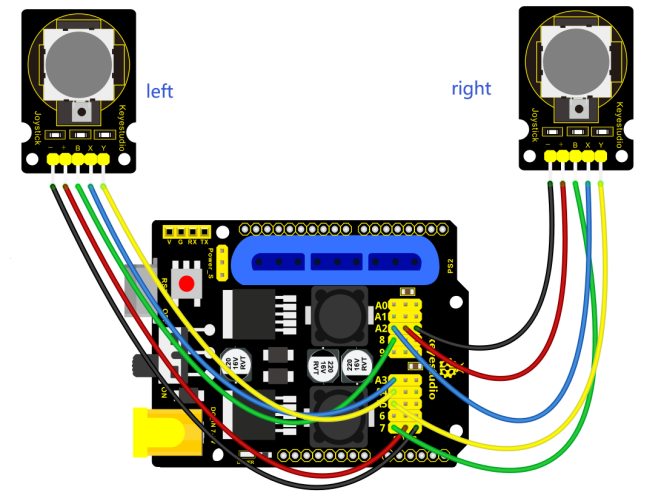
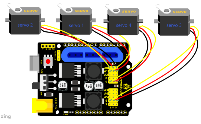
Test Code 6:
#include <Servo.h>  // add the servo libraries
Servo myservo1;  // create servo object to control a servo
Servo myservo2;
Servo myservo3;
Servo myservo4;
int pos1=80, pos2=60, pos3=130, pos4=0;  //  define the variable of 4 servo angle and assign the initial value( that is the boot posture angle value)

const int right_X = A2; //  define the right X pin to A2
const int right_Y = A5; // define the right Y pin to A5
const int right_key = 7; // define the right key pin to 7(that is Z value)

const int left_X = A3; //  define the left X pin to A3
const int left_Y = A4;  //  define the left Y pin to A4
const int left_key = 8; // define the left key pin to 8(that is Z value)

int x1,y1,z1;  //define the variable, used to save the joystick value.
int x2,y2,z2;
int s1,s2,s3,s4;
int jiyi1[10];  // define 4 array, separately used to save the angle of four servo.
int jiyi2[10];  //(array length is 10,namely can save angle data of 0~10 servo )
int jiyi3[10];  // if need to save more data, just change the number 10 to be more larger number.
int jiyi4[10];
int i=0; // for loop
int j=0; // save the last value of i

void setup()
{
 // boot posture
 myservo1.write(pos1);
 delay(1000);
 myservo2.write(pos2);
 myservo3.write(pos3);
 myservo4.write(pos4);
 delay(1500);


 pinMode(right_key, INPUT);  // set the right/left key to INPUT
 pinMode(left_key, INPUT);
 Serial.begin(9600); //  set baud rate to 9600
}

void loop()
{
 myservo1.attach(A1);  // set the control pin of servo 1 to A1
 myservo2.attach(A0);  // set the control pin of servo 2 to A0
 myservo3.attach(6);  // set the control pin of servo 3 to D6
 myservo4.attach(9);  // set the control pin of servo 4 to D9

 x1 = analogRead(right_X); // read the right X value
 y1 = analogRead(right_Y);  // read the right Y value
 z1 = digitalRead(right_key);  // read the right Z value

 x2 = analogRead(left_X);  // read the left X value
 y2 = analogRead(left_Y);  // read the left Y value
 z2 = digitalRead(left_key);  // read the left Z value
 //delay(5);  // reduce the speed overall
 if(z1==1)  // if the right joystick key is pressed
 {
  delay(10);  // delay for eliminating shake
  if(z1==1)  // judge again if the right key is pressed
  {
   s1=myservo1.read();   // read the angle value of each servo
   delay(100);
   Serial.println(s1);
   s2=myservo2.read();
   delay(100);
   Serial.println(s2);
   s3=myservo3.read();
   delay(100);
   Serial.println(s3);
   s4=myservo4.read();
   delay(100);
   Serial.println(s4);

   jiyi1[i]=s1;  // Save the read servo value to the array sequentially
   jiyi2[i]=s2;
   jiyi3[i]=s3;
   jiyi4[i]=s4;
   i++;   //i value plus 1
   j=i;   // assign the last value of i to j
   delay(100);
   Serial.println(i);  // on the serial monitor, print out the value i
  }
 }

 if(z2==1) // if the left joystick key is pressed
 {
  delay(10);
  if(z2==1)  // judge again if the left key is pressed
  {
   i=0;  // assign i to 0,prepare for the next memory
   pos1 = myservo1.read();   // memorize the angle value of 4 servo posture
   pos2 = myservo2.read();
   pos3 = myservo3.read();
   pos4 = myservo4.read();

   for(int k=0;k<j;k++)  // loop for j times, perform all actions saved.
   {
    if(pos1<jiyi1[k])   // if the current servo 1 angle is less than the value stored in array 1.
    {
     while(pos1<jiyi1[k])  //while loop, make servo turn to the position of value stored in the array.
     {
      myservo1.write(pos1);  // servo 1 performs the action
      delay(5);   // delay 5ms,controlling the servo rotating speed
      pos1++;  //pos1 plus 1
      //Serial.println(pos1);
     }
    }
    else   // if the current servo 1 angle is greater than the value stored in array 1.
    {
     while(pos1>jiyi1[k])   //while loop, make servo turn to the position of value stored in the array.
     {
      myservo1.write(pos1);  // servo 1 performs the action
      delay(5);   //delay 5ms,controlling the servo rotating speed
      pos1--;   //pos1 subtracts 1
      //Serial.println(pos1);
     }
    }
//***************************************************************
 //the explanation is the same as the previous servo
    if(pos2<jiyi2[k])
    {
     while(pos2<jiyi2[k])
     {
      myservo2.write(pos2);
      delay(5);
      pos2++;
      //Serial.println(pos1);
     }
    }
    else
    {
     while(pos2>jiyi2[k])
     {
      myservo2.write(pos2);
      delay(5);
      pos2--;
      //Serial.println(pos1);
     }
    }
 //***************************************************************
 // the explanation is the same as the previous servo

    if(pos3<jiyi3[k])
    {
     while(pos3<jiyi3[k])
     {
      myservo3.write(pos3);
      delay(5);
      pos3++;
      //Serial.println(pos1);
     }
    }
    else
    {
     while(pos3>jiyi3[k])
     {
      myservo3.write(pos3);
      delay(5);
      pos3--;
      //Serial.println(pos1);
     }
    }
 //***************************************************************
 //the explanation is the same as the previous servo

    if(pos4<jiyi4[k])
    {
     while(pos4<jiyi4[k])
     {
      myservo4.write(pos4);
      delay(5);
      pos4++;
      //Serial.println(pos1);
     }
    }
    else
    {
     while(pos4>jiyi4[k])
     {
      myservo4.write(pos4);
      delay(5);
      pos4--;
      //Serial.println(pos1);
     }
    }
   }
  }
 }

 //claw
 zhuazi();
 //turn
 zhuandong();
 //upper arm
 xiaobi();
 // lower arm
 dabi();
}


//claw
void zhuazi()
{
  //claw
 if(x2<50) // if push the left joystick to the right
 {
   pos4=pos4-2;  // angle of servo 4, subtract 2 (change the value you subtract, thus change the closed speed of claw)
   //Serial.println(pos4);
   myservo4.write(pos4);  // servo 4 operates the motion and claw is gradually closed.
   delay(5);
   if(pos4<2)  // if pos4 value subtracts to 2, the claw in 37 degrees we have tested is closed.)
   {       //(should change the value based on the fact)
    pos4=2;  // stop subtraction when reduce to 2
   }
  }
 if(x2>1000) //// if push the left joystick to the left
 {
   pos4=pos4+8; // current angle of servo 4 plus 8(change the value you plus, thus change the open speed of claw)
   //Serial.println(pos4);
   myservo4.write(pos4); //  servo 4 operates the action, claw gradually opens.
   delay(5);
   if(pos4>90)  // limit the largest angle opened
   {
    pos4=90;
   }
 }
}
//******************************************************
 // turn
void zhuandong()
{
 if(x1<50)  // if push the right joystick to the right
 {
  pos1=pos1-1;  //pos1 subtracts 1
  myservo1.write(pos1);  // servo 1 operates the motion and robot arm turns right
  delay(5);
  if(pos1<1)  // limit the angle when turn right
  {
   pos1=1;
  }
 }
 if(x1>1000)  // if push the right joystick to the left
 {
  pos1=pos1+1;  //pos1 plus 1
  myservo1.write(pos1);  // robot arm turns left
  delay(5);
  if(pos1>180)  // limit the angle when turn left
  {
   pos1=180;
  }
 }
}

//************************************************
// upper arm
void xiaobi()
{
  if(y1>1000) // if push the right joystick upward
 {
  pos2=pos2-1;
  myservo2.write(pos2); // the upper arm will lift
  delay(5);
  if(pos2<0)  // limit the lifting angle
  {
   pos2=0;
  }
 }
 if(y1<50)  // if push the right joystick downward
 {
  pos2=pos2+1;
  myservo2.write(pos2);  // the upper arm will go down
  delay(5);
  if(pos2>180)  // limit the declining angle
  {
   pos2=180;
  }
 }
}

//*************************************************************/
// lower arm
void dabi()
{
 if(y2>1000)  // if push the left joystick upward
 {
  pos3=pos3-1;
  myservo3.write(pos3);  // the lower arm will stretch out
  delay(5);
  if(pos3<35)  // limit the stretched angle
  {
   pos3=35;
  }
 }

 if(y2<50)  // if push the left joystick downward
 {
  pos3=pos3+1;
  myservo3.write(pos3);  // the lower arm will draw back
  delay(5);
  if(pos3>180)  // limit the retracted angle
  {
   pos3=180;
  }
 }
}
Test Result:
Wire it up, stack the shield onto V4.0, upload the code. Powered on, press the key Z1 of right Joystick to save the angle value of 4 servos. Press down the key Z1 to memorize different postures, at most 10 postures in the code. If need to memorize more postures, you can set it in the code. When memorizing successfully, press down the key Z2 of left Joystick to make the robot arm carry out several postures stored successively.
Move the thumbsticks and press the button of right thumbstick, then move them and press the right button again. That indicates that actions of the arm are memorized. Next, you can press the left button to perform actions saved.
Memorize Several Postures And Loop
Description:
In the previous section, we have introduced how to make 4DOF robot arm to memorize and perform a group of posture. Furthermore, let’s extend one more loop function. When the robot arm performs all the memorized actions, it will not
stop, and continue to repeat those actions.
In the following experiment, press the key Z1, 4DOF robot arm will exit the looping action. Press the key Z1 again, start to memorize the posture, after that, press the key Z2 to loop the memorized actions.
Hookup Guide:
Test Code 7:
#include <Servo.h> // add the servo libraries
Servo myservo1; // create servo object to control a servo
Servo myservo2;
Servo myservo3;
Servo myservo4;
int pos1=80, pos2=60, pos3=130, pos4=0; // define the variable of 4 servo angle
and assign the initial value( that is the boot posture angle value)
const int right_X = A2; // define the right X pin to A2
const int right_Y = A5; // define the right Y pin to A5
const int right_key = 7; // define the right key pin to 7(that is Z value)
const int left_X = A3; //define the left X pin to A3
const int left_Y = A4; // define the left Y pin to A4
const int left_key = 8; // define the left key pin to 8(that is Z value)
int x1,y1,z1; // define the variable, used to save the joystick value.
int x2,y2,z2;
int s1,s2,s3,s4;
int jiyi1[20]; //define 4 array, separately used to save the angle of four
servo.
int jiyi2[20]; // (array length is 20,namely can save angle data of 0~20
servo)
int jiyi3[20]; //if need to save more data, just change the number 20 to be more
larger number.
int jiyi4[20];
int i=0; // for loop
int j=0; // save the last value of i
void setup()
{
// boot posture
myservo1.write(pos1); //turn servo 1 to 90 degrees
delay(1000);
myservo2.write(pos2); // turn servo 2 to 90 degrees
myservo3.write(pos3); // turn servo 3 to 120 degrees
myservo4.write(pos4); // turn servo 4 to 35 degrees
delay(1500);
pinMode(right_key, INPUT); // set the right/left key to INOUT
pinMode(left_key, INPUT);
Serial.begin(9600); // set the baud rate to 9600
}
void loop()
{
myservo1.attach(A1); // set the control pin of servo 1 to A1
myservo2.attach(A0); // set the control pin of servo 2 to A0
myservo3.attach(6); //set the control pin of servo 3 to D6
myservo4.attach(9); // set the control pin of servo 4 to D9
x1 = analogRead(right_X); // read the right X value
y1 = analogRead(right_Y); //read the right Y value
z1 = digitalRead(right_key); //read the right Z value
x2 = analogRead(left_X); // read the left X value
y2 = analogRead(left_Y); // read the left Y value
z2 = digitalRead(left_key); // read the left Z value
//delay(5); // delay, used to reduce the joystick value read, that is reduce the
whole speed.
if(z1==1) // if the joystick right key is pressed
{
delay(10); // delay for eliminating shake
if(z1==1) // judge again if the right key is pressed
{
s1=myservo1.read(); // read the angle value of servo 1 and assign it to s1
delay(100);
Serial.println(s1); // print out the angle value of servo 1 on the serial
monitor
s2=myservo2.read(); // read the angle value of servo 2 and assign it to s2
delay(100);
Serial.println(s2);
s3=myservo3.read(); // read the angle value of servo 3 and assign it to s3
delay(100);
Serial.println(s3);
s4=myservo4.read(); // read the angle value of servo 4 and assign it to s4
delay(100);
Serial.println(s4);
jiyi1[i]=s1; // Save the read servo value to the array sequentially
jiyi2[i]=s2;
jiyi3[i]=s3;
jiyi4[i]=s4;
i++; //i plus 1
j=i; // assign the last value of i to j
delay(100); // delay 100ms
Serial.println(i); // print out the value i
}
}
if(z2==1) // if the left joystick key is pressed
{
delay(10); // delay for eliminating shake
if(z2==1) //judge again if the left key is pressed
{
pos1 = myservo1.read(); // memorize the angle value of 4 servo posture
pos2 = myservo2.read();
pos3 = myservo3.read();
pos4 = myservo4.read();
while(z2==1) // loop, make the arm repeat the action.
{
for(int k=1;k<j;k++) //for loop, perform all the stored actions.
{
if(pos1<jiyi1[k]) // if the current servo 1 angle is less than the value stored
in array 1.
{
while(pos1<jiyi1[k]) //while loop, make servo turn to the position of value
stored in the array.
{
myservo1.write(pos1); //servo 1 performs the action
delay(5); //delay 5ms,controlling the servo rotating speed.
pos1++; //pos1 plus 1
//Serial.println(pos1);
}
}
else //if the current servo 1 angle is greater than the value stored in array 1.
{
while(pos1>jiyi1[k]) //while loop, make servo turn to the position of value
stored in the array.
{
myservo1.write(pos1); //servo 1 performs the action
delay(5); //delay 5ms,controlling the servo rotating speed.
pos1--; //pos1 subtracts 1
//Serial.println(pos1);
}
}
//***************************************************************
//the explanation is the same as the previous servo.
if(pos2<jiyi2[k])
{
while(pos2<jiyi2[k])
{
myservo2.write(pos2);
delay(5);
pos2++;
//Serial.println(pos1);
}
}
else
{
while(pos2>jiyi2[k])
{
myservo2.write(pos2);
delay(5);
pos2--;
//Serial.println(pos1);
}
}
//*********************************************
//the explanation is the same as the previous servo.
if(pos3<jiyi3[k])
{
while(pos3<jiyi3[k])
{
myservo3.write(pos3);
delay(5);
pos3++;
//Serial.println(pos1);
}
}
else
{
while(pos3>jiyi3[k])
{
myservo3.write(pos3);
delay(5);
pos3--;
//Serial.println(pos1);
}
}
//*********************************************
//the explanation is the same as the previous servo.
if(pos4<jiyi4[k])
{
while(pos4<jiyi4[k])
{
myservo4.write(pos4);
delay(5);
pos4++;
//Serial.println(pos1);
}
}
else
{
while(pos4>jiyi4[k])
{
myservo4.write(pos4);
delay(5);
pos4--;
//Serial.println(pos1);
}
}
}
//************************************************************
// for exiting the loop
z1 = digitalRead(right_key); // read the right Z value
if(z1==1) // if the right key is pressed
{
delay(10); //eliminate the shake
if(z1==1) // if the key z1 is pressed
{
pos1=jiyi1[(j-1)]; // assign the last angle value saved in array to pos
pos2=jiyi2[(j-1)]; // for exiting the loop, still access to joystick control.
pos3=jiyi3[(j-1)];
pos4=jiyi4[(j-1)];
i=0; // assign i as 0,prepare for saving the angle value using array
z2=0; // assign z2 as 0,for exiting the while loop
break; //exit the current loop
}
}
//********************************************************
}
}
}
//claw
zhuazi();
//turn
zhuandong();
//upper arm
xiaobi();
//lower arm
dabi();
}
//claw
void zhuazi()
{
//claw
if(x2<50) // if push the left joystick to the right
{
pos4=pos4-2; // angle of servo 4, subtract 2 (change the value you subtract,
thus change the closed speed of claw)
//Serial.println(pos4);
myservo4.write(pos4); // servo 4 operates the motion and claw is gradually
closed.
delay(5);
if(pos4<2) // if pos4 value subtracts to 2, the claw in 37 degrees we have
tested is closed.)
{ //(should change the value based on the fact)
pos4=2; //stop subtraction when reduce to 2
}
}
if(x2>1000) ////if push the left joystick to the left
{
pos4=pos4+8; //current angle of servo 4 plus 8(change the value you plus, thus
change the open speed of claw)
//Serial.println(pos4);
myservo4.write(pos4); // servo 4 operates the action, claw gradually opens.
delay(5);
if(pos4>90) //limit the largest angle opened
{
pos4=90;
}
}
}
//******************************************************
//turn
void zhuandong()
{
if(x1<50) //if push the right joystick to the right
{
pos1=pos1-1; //pos1 subtracts 1
myservo1.write(pos1); // servo 1 performs the action, the robot arm turns right.
delay(5);
if(pos1<1) // limit the right turning angle
{
pos1=1;
}
}
if(x1>1000) // if push the right joystick to the left
{
pos1=pos1+1; //pos1 plus 1
myservo1.write(pos1); //the robot arm turns left.
delay(5);
if(pos1>180) //limit the left turning angle
{
pos1=180;
}
}
}
//**********************************************************/
// upper arm
void xiaobi()
{
if(y1>1000) // if push the right joystick upward
{
pos2=pos2-1;
myservo2.write(pos2); // the robot arm will lift
delay(5);
if(pos2<0) // limit the lifting angle
{
pos2=0;
}
}
if(y1<50) // if push the right joystick downward
{
pos2=pos2+1;
myservo2.write(pos2); // the robot arm will go down
delay(5);
if(pos2>180) // limit the declining angle
{
pos2=180;
}
}
}
//*************************************************************/
// lower arm
void dabi()
{
if(y2>1000) // if push the left joystick upward
{
pos3=pos3-1;
myservo3.write(pos3); // the lower arm will stretch out
delay(5);
if(pos3<35) // limit the stretched angle
{
pos3=35;
}
}
if(y2<50) // if push the right joystick downward
{
pos3=pos3+1;
myservo3.write(pos3); // the lower arm will draw back
delay(5);
if(pos3>180) // limit the retraction angle
{
pos3=180;
}
}
}
Test Result:
Wire it up, stack the shield onto V4.0, upload the code. Powered on, press the key Z1 of right Joystick to save the angle value of 4 servos. Press down the key Z1 to memorize different postures, at most 10 postures in the code. If need to memorize more postures, can set it in the code.
When memorizing successfully, press down the key Z2 of left Joystick to make the robot arm carry out several postures stored successively, looping.
Long press the key Z1, 4DOF robot arm will exit the looping action. Press the key Z1 again, start to memorize the posture, after that, press the key Z2 to loop the memorized actions.
Move the thumbsticks and press the button of right thumbstick, then move them and press the right button again. That indicates that actions of the arm are memorized. Next, you can press the left button to perform actions saved.
Project 4: BT-controlled Robot Arm
Principle of BT Control
Bluetooth technology is a wireless standard technology that can realize short-distance data exchange between fixed equipment, mobile equipment andpersonal area network (UHF radio waves in the ISM band of 2.4-2.485GHz). In the kit, we equip with the BT-24 Bluetooth module. BT-24 Bluetooth module supports Android and IOS system.
In the experiment, we default the BT-24 Bluetooth module as the slave and the mobile phone as the master.We especially design APP to control robotic arm(Android /IOS system).
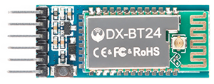
Specification
Bluetooth protocol: Bluetooth Specification V5.1 BLE
Working distance: In an open environment, achieve 40m ultra-long distance communication
Operating frequency: 2.4GHz ISM band
Communication interface: UART
Bluetooth certification: in line with FCC CE ROHS REACH certification standards
Serial port parameters: 9600, 8 data bits, 1 stop bit, invalid bit, no flow control
Power: 5V DC
Operating temperature: –10 to +65 degrees Celsius
Bluetooth Control Key Test
Description
Next, we are going to introduce the use method for BT-24 Bluetooth module. To easily use the BT-24 Bluetooth module to control the robot arm, we particularly design the APP control. Shown below.
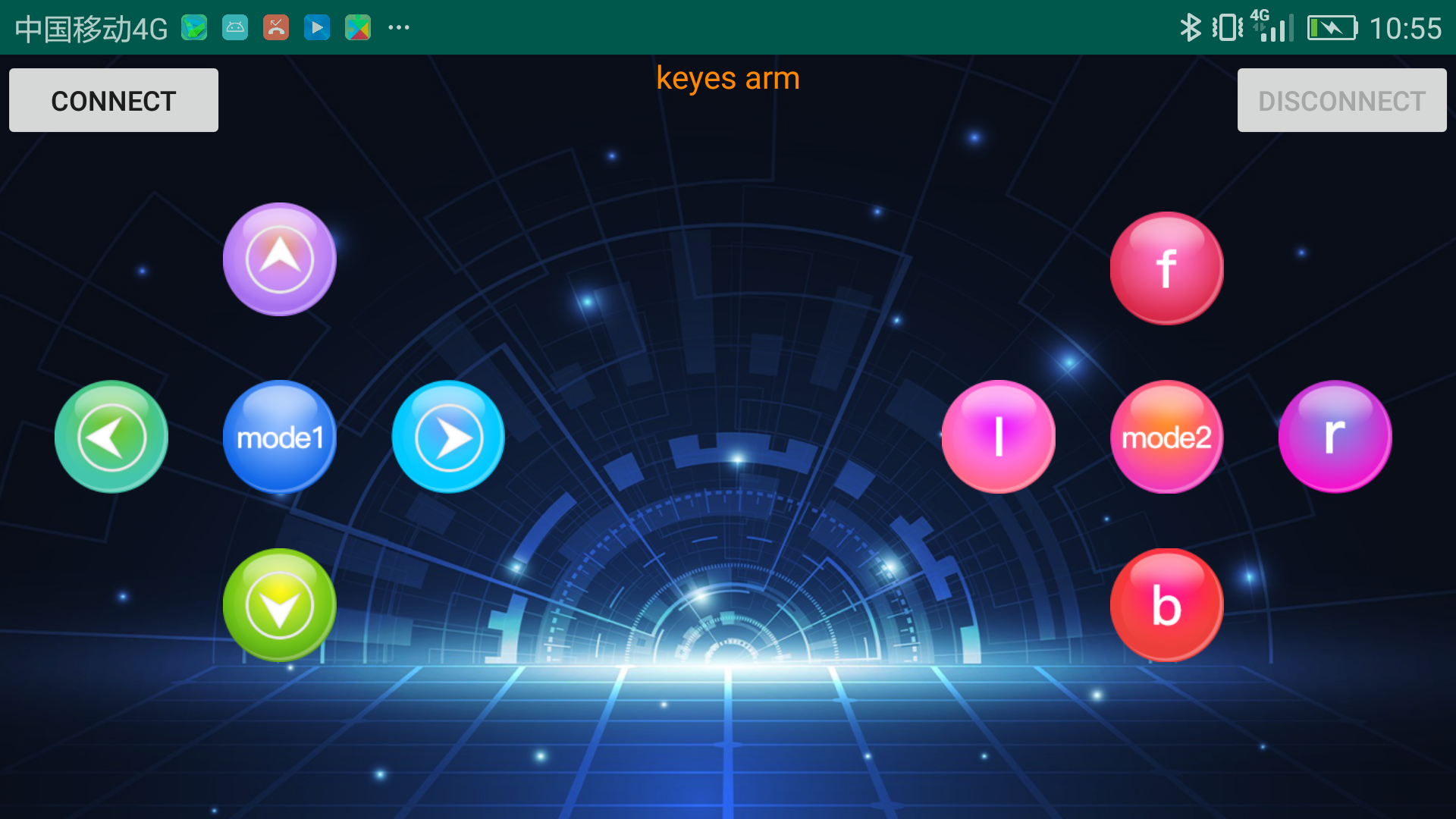
There are 10 control keys on the App. When connect well the HC-06 Bluetooth module to Android phone using our APP, press the control key, Android phone will receive a corresponding value.
When programming, you can set the function for the corresponding value. So in the experiment, we will test each key to get the corresponding value.
Installation Steps for Android system:
APP for Android mobile:
Enter google play,search “keyes arm”.
https://play.google.com/store/apps/details?id=com.keyestudio.keyes_arm_123
Note: Allow APP to access “location” in settings of your cellphone when connecting to Bluetooth module, otherwise, Bluetooth may not be connected.
This are operating steps as below, the interface for Android and ios system is same.
Android System:
-
Download and install
 ,the
,the
interface shown below: -
Upload code and power on, Led of Bluetooth module blinks. Start Bluetooth and open App to click “CONNECT” to connect.
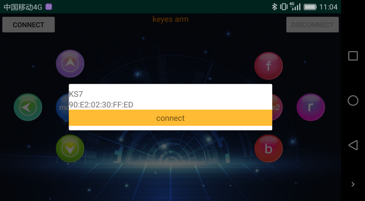
-
Upload code on control board, after power-on, LED blinks on Bluetooth module. Start Bluetooth and open App to click “connect”, Bluetooth is connected.

For IOS system:
-
Open App Store

-
Search “keyes arm”on APP Store,then click “downlaod”.
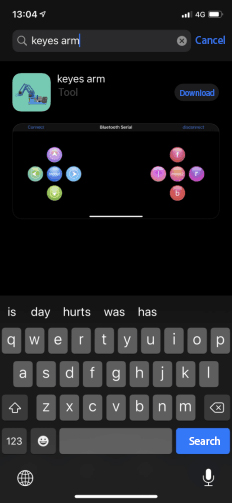
Special Note: Remove the Bluetooth module please, when uploading the Test Code. Otherwise, the program will fail to upload. After uploading the Test Code, then connect the Bluetooth and Bluetooth module to pair.
Connection Diagram
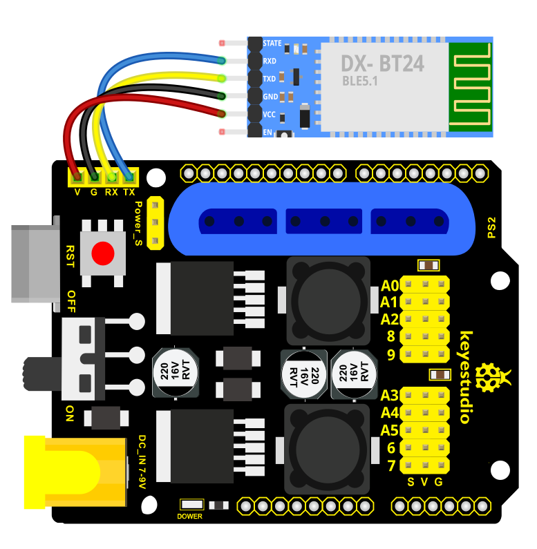
Test Code
void setup()
{
Serial.begin(9600); // set the serial baud rate to 9600
}
void loop()
{
char val; // define a variable, used to receive the value read from Bluetooth.
if(Serial.available()) // if receive the value
{
val = Serial.read(); // assign the value read to val
Serial.println(val);
}
}
After connecting Bluetooth module, open serial port monitor to set baud rate to
9600. Press control keys on App, the serial port prints out the corresponding
control character. As shown below:
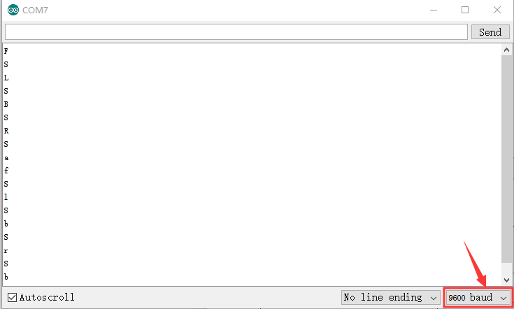
Test Result:
The functions of control keys:
|
|
Connect APP to bt-24 Bluetooth module |
|
|
|
Turn off Bluetooth |
|
|
|
Press to send“F” Release to send“S” |
Left servo goes front Left servo stops motion |
|
|
Press to send “L” Release to send“S” |
Clamp claw opens Clamp claw stops |
|
|
Mode 1 |
|
|
|
Press to send “R” Release to send“S” |
Clamp claw closes Clamp claw stops |
|
|
Press to send “B” Release to send“S” |
Left Servo draws back Left Servo stops motion |
|
|
Press to send “f” Release to send“S” |
Right servo stretches out Right servo stops motion |
|
|
Press to send “l” Release to send“S” |
The base servo turns left Base servo stops |
|
|
Mode 2 |
—————— |
|
|
Press to send “r” Release to send“S” |
Base Servo turns right Base Servo stops |
|
|
Press to send “b” Release to send“S” |
Right Servo draws back Right Servo stops |


Bluetooth Controls the Robotic Arm
Description
We introduced the control method of the 4-DOF robot arm and bt-24 Bluetooth module. In this experiment, we’ll control 4DOF robotic arm movement via APP.
Note: After uploading test code successfully, unplug the USB data cable and power up via external power supply and control 4 DOF robot arm movement via APP.
Connection Diagram
Test Code
#include <Servo.h> // add the servo libraries
Servo myservo1; // create servo object to control a servo
Servo myservo2;
Servo myservo3;
Servo myservo4;
int pos1=80, pos2=60, pos3=130, pos4=0; // define the variable of 4 servo angle
and assign the initial value( that is the boot posture angle value)
char val;
char val2;
void setup()
{
// boot posture
myservo1.write(pos1);
delay(1000);
myservo2.write(pos2);
myservo3.write(pos3);
myservo4.write(pos4);
delay(1500);
Serial.begin(9600); // set the baud rate to 9600
}
void loop()
{
myservo1.attach(A1); // set the control pin of servo 1 to A1
myservo2.attach(A0); // set the control pin of servo 2 to A0
myservo3.attach(6); // set the control pin of servo 3 to D6
myservo4.attach(9); // set the control pin of servo 4 to D9
if(Serial.available()) // if receive the data
{
val=Serial.read(); // read the received data
val2=val; //Give the value of val to val2
Serial.println(val);
switch(val)
{
case 'L': T_left(); break; // execute the corresponding function when receive
the value
case 'R': T_right(); break;
case 'f': RF(); break;
case 'b': rb(); break;
case 'F': ZK(); break;
case 'B': ZB(); break;
case 'l': LF(); break;
case 'r': lb(); break;
case 'S': servo_stop(); break; //stop instruction
}
}
else
{
switch(val2) //When the button is pressed and not released,
{ //"else" is executed because Bluetooth does not send characters,
// and the value of val2 is the value of the previously pressed button,
//so the command of pressing the button will be repeated
case 'L': T_left(); break; // execute the corresponding function when receive
the value
case 'R': T_right(); break;
case 'f': RF(); break;
case 'b': rb(); break;
case 'F': ZK(); break;
case 'B': ZB(); break;
case 'l': LF(); break;
case 'r': lb(); break;
case 'S': servo_stop(); break; //stop instruction
}
}
}
//**************************************************
// turn left
void T_left()
{
pos1=pos1+1;
myservo1.write(pos1);
delay(5);
if(pos1>180)
{
pos1=180;
}
}
//turn right
void T_right()
{
pos1=pos1-1;
myservo1.write(pos1);
delay(5);
if(pos1<1)
{
pos1=1;
}
}
//********************************************
//open the claw
void ZK()
{
pos4=pos4-2;
Serial.println(pos4);
myservo4.write(pos4);
delay(5);
if(pos4<2)
{
pos4=0;
}
}
// close the claw
void ZB()
{
pos4=pos4+8;
Serial.println(pos4);
myservo4.write(pos4);
delay(5);
if(pos4>108)
{
pos4=108;
}
}
//******************************************
// the upper arm will lift up
void RF()
{
pos2=pos2-1;
myservo2.write(pos2);
delay(5);
if(pos2<0)
{
pos2=0;
}
}
// the upper arm will go down
void rb()
{
pos2=pos2+1;
myservo2.write(pos2);
delay(5);
if(pos2>180)
{
pos2=180;
}
}
//***************************************
// the lower arm will stretch out
void lb()
{
pos3=pos3+1;
myservo3.write(pos3);
delay(5);
if(pos3>180)
{
pos3=180;
}
}
// the lower arm will draw back
void LF()
{
pos3=pos3-1;
myservo3.write(pos3);
delay(5);
if(pos3<35)
{
pos3=35;
}
}
void servo_stop()
{
myservo1.write(pos1);
myservo2.write(pos2);
myservo3.write(pos3);
myservo4.write(pos4);
}
Test Result:
Upload the code, connect it up and power on, after connecting the Bluetooth APP, press the key to control the robot arm do commanded motions.
Project 5: PS2-controlled Robot Arm (Extension)
5.1 PS2 Joypad Key Test
Description:
On the drive shield there is a PS2 Joystick connector, which is easy for you to control the 4DOF robot arm using the PS2 Joypad. But you need to purchase it by yourself because the PS2 Joypad is not included in the kit.
When use the PS2 Joypad to control the robot arm, first need to get the corresponding character of each key on the PS2 Joypad.
So this experiment will help you test the character of each key on the PS2 Joypad.
After connecting the Joypad, should upload the test program on Arduino IDE. But before testing, should place the PS2X_lib folder inside the libraries folder of Arduino IDE directory.
Uploading the code, open the serial monitor, connect the PS2 Joypad. When press down the key, you should see the corresponding character on the monitor.
Test Code 10:
#include <PS2X_lib.h>  //for v1.6
PS2X ps2x; // create PS2 Controller Class
//right now, the library does NOT support hot pluggable controllers, meaning
//you must always either restart your Arduino after you conect the controller,
//or call config_gamepad(pins) again after connecting the controller.
int error = 0;
byte type = 0;
byte vibrate = 0;
void setup(){
 Serial.begin(57600);
 //CHANGES for v1.6 HERE!!! **************PAY ATTENTION*************

 error = ps2x.config_gamepad(13,11,10,12, true, true);   //setup pins and settings:  GamePad(clock, command, attention, data, Pressures?, Rumble?) check for error

 if(error == 0){
   Serial.println("Found Controller, configured successful");
   Serial.println("Try out all the buttons, X will vibrate the controller, faster as you press harder;");
  Serial.println("holding L1 or R1 will print out the analog stick values.");
  Serial.println("Go to www.billporter.info for updates and to report bugs.");
 }

  else if(error == 1)
   Serial.println("No controller found, check wiring, see readme.txt to enable debug. visit www.billporter.info for troubleshooting tips");

  else if(error == 2)
   Serial.println("Controller found but not accepting commands. see readme.txt to enable debug. Visit www.billporter.info for troubleshooting tips");

  else if(error == 3)
   Serial.println("Controller refusing to enter Pressures mode, may not support it. ");

   //Serial.print(ps2x.Analog(1), HEX);

   type = ps2x.readType();
     switch(type) {
       case 0:
        Serial.println("Unknown Controller type");
       break;
       case 1:
        Serial.println("DualShock Controller Found");
       break;
       case 2:
         Serial.println("GuitarHero Controller Found");
       break;
     }

}
void loop(){
   /* You must Read Gamepad to get new values
   Read GamePad and set vibration values
   ps2x.read_gamepad(small motor on/off, larger motor strenght from 0-255)
   if you don't enable the rumble, use ps2x.read_gamepad(); with no values

   you should call this at least once a second
   */


 if(error == 1) //skip loop if no controller found
  return;

 if(type == 2){ //Guitar Hero Controller

   ps2x.read_gamepad();          //read controller

   if(ps2x.ButtonPressed(GREEN_FRET))
     Serial.println("Green Fret Pressed");
   if(ps2x.ButtonPressed(RED_FRET))
     Serial.println("Red Fret Pressed");
   if(ps2x.ButtonPressed(YELLOW_FRET))
     Serial.println("Yellow Fret Pressed");
   if(ps2x.ButtonPressed(BLUE_FRET))
     Serial.println("Blue Fret Pressed");
   if(ps2x.ButtonPressed(ORANGE_FRET))
     Serial.println("Orange Fret Pressed");

    if(ps2x.ButtonPressed(STAR_POWER))
     Serial.println("Star Power Command");

    if(ps2x.Button(UP_STRUM))          //will be TRUE as long as button is pressed
     Serial.println("Up Strum");
    if(ps2x.Button(DOWN_STRUM))
     Serial.println("DOWN Strum");


    if(ps2x.Button(PSB_START))                   //will be TRUE as long as button is pressed
         Serial.println("Start is being held");
    if(ps2x.Button(PSB_SELECT))
         Serial.println("Select is being held");

    if(ps2x.Button(ORANGE_FRET)) // print stick value IF TRUE
    {
        Serial.print("Wammy Bar Position:");
        Serial.println(ps2x.Analog(WHAMMY_BAR), DEC);
    }
 }
 else { //DualShock Controller

    ps2x.read_gamepad(false, vibrate);          //read controller and set large motor to spin at 'vibrate' speed

    if(ps2x.Button(PSB_START))                   //will be TRUE as long as button is pressed
         Serial.println("Start is being held");
    if(ps2x.Button(PSB_SELECT))
         Serial.println("Select is being held");


     if(ps2x.Button(PSB_PAD_UP)) {         //will be TRUE as long as button is pressed
       Serial.print("Up held this hard: ");
       Serial.println(ps2x.Analog(PSAB_PAD_UP), DEC);
      }
      if(ps2x.Button(PSB_PAD_RIGHT)){
       Serial.print("Right held this hard: ");
        Serial.println(ps2x.Analog(PSAB_PAD_RIGHT), DEC);
      }
      if(ps2x.Button(PSB_PAD_LEFT)){
       Serial.print("LEFT held this hard: ");
        Serial.println(ps2x.Analog(PSAB_PAD_LEFT), DEC);
      }
      if(ps2x.Button(PSB_PAD_DOWN)){
       Serial.print("DOWN held this hard: ");
     Serial.println(ps2x.Analog(PSAB_PAD_DOWN), DEC);
      }


      vibrate = ps2x.Analog(PSAB_BLUE);        //this will set the large motor vibrate speed based on
                                              //how hard you press the blue (X) button

    if (ps2x.NewButtonState())               //will be TRUE if any button changes state (on to off, or off to on)
    {


        if(ps2x.Button(PSB_L3))
         Serial.println("L3 pressed");
        if(ps2x.Button(PSB_R3))
         Serial.println("R3 pressed");
        if(ps2x.Button(PSB_L2))
         Serial.println("L2 pressed");
        if(ps2x.Button(PSB_R2))
         Serial.println("R2 pressed");
        if(ps2x.Button(PSB_GREEN))
         Serial.println("Triangle pressed");

    }


    if(ps2x.ButtonPressed(PSB_RED))             //will be TRUE if button was JUST pressed
         Serial.println("Circle just pressed");

    if(ps2x.ButtonReleased(PSB_PINK))             //will be TRUE if button was JUST released
         Serial.println("Square just released");

    if(ps2x.NewButtonState(PSB_BLUE))            //will be TRUE if button was JUST pressed OR released
         Serial.println("X just changed");


    if(ps2x.Button(PSB_L1) || ps2x.Button(PSB_R1)) // print stick values if either is TRUE
    {
        Serial.print("Stick Values:");
        Serial.print(ps2x.Analog(PSS_LY), DEC); //Left stick, Y axis. Other options: LX, RY, RX
        Serial.print(",");
        Serial.print(ps2x.Analog(PSS_LX), DEC);
        Serial.print(",");
        Serial.print(ps2x.Analog(PSS_RY), DEC);
        Serial.print(",");
        Serial.println(ps2x.Analog(PSS_RX), DEC);
    }


 }


 delay(50);

}
Test Result:
Stack the drive shield onto V4.0 and upload the code. Connecting the PS2 Joypad, open the serial monitor and set the baud rate to 57600. When press down the key or push the rocker, you should see the corresponding character showed on the monitor.
5.2 PS2 Joypad Control
Description:
In the previous section, we have showed how to use Joystick module to control the robot arm. It is almost the same for you to control the 4DOF robot arm using the PS2 Joypad.
PS2 Joystick Control
|
Right Joystick |
Robot Arm |
Left Joystick |
Robotic Claw |
|---|---|---|---|
|
Push to the right side |
Rotate to right |
Push to the right side |
close |
|
Push to the left side |
Rotate to left |
Push to the left side |
open |
|
Push forward |
The small arm will lift |
Push forward |
The large arm will move forward |
|
Push back |
The small arm will lower |
Push back |
The large arm will move back |
Connection Diagram
Test Code
#include <PS2X_lib.h>
PS2X ps2x; // create PS2 Controller Class
//right now, the library does NOT support hot pluggable controllers, meaning
//you must always either restart your Arduino after you connect the controller,
//or call config_gamepad(pins) again after connecting the controller.
int error = 0;
byte vibrate = 0;
#include <Servo.h> // add the servo libraries
Servo myservo1; // create servo object to control a servo
Servo myservo2;
Servo myservo3;
Servo myservo4;
int pos1=80, pos2=60, pos3=130, pos4=0; // define the variable of 4 servo angle
and assign the initial value( that is the boot posture angle value)
void setup(){
Serial.begin(57600);
// boot posture
myservo1.write(pos1);
delay(1000);
myservo2.write(pos2);
myservo3.write(pos3);
myservo4.write(pos4);
delay(1500);
error = ps2x.config_gamepad(13,11,10,12); //setup GamePad(clock, command,
attention, data) pins, check for error
if(error == 0){
Serial.println("Found Controller, configured successful");
Serial.println("Try out all the buttons, X will vibrate the controller, faster
as you press harder;");
Serial.println("holding L1 or R1 will print out the analog stick values.");
Serial.println("Go to www.billporter.info for updates and to report bugs.");
}
else if(error == 1)
Serial.println("No controller found, check wiring, see readme.txt to enable
debug. visit www.billporter.info for troubleshooting tips");
else if(error == 2)
Serial.println("Controller found but not accepting commands. see readme.txt to
enable debug. Visit www.billporter.info for troubleshooting tips");
//Serial.print(ps2x.Analog(1), HEX);
ps2x.enableRumble(); //enable rumble vibration motors
ps2x.enablePressures(); //enable reading the pressure values from the buttons.
}
void loop(){
/* You must Read Gamepad to get new values
Read GamePad and set vibration values
ps2x.read_gamepad(small motor on/off, larger motor strenght from 0-255)
if you don't enable the rumble, use ps2x.read_gamepad(); with no values
you should call this at least once a second
*/
myservo1.attach(A1); // set the control pin of servo 1 to A1
myservo2.attach(A0); // set the control pin of servo 2 to A0
myservo3.attach(6); // set the control pin of servo 3 to D6
myservo4.attach(9); // set the control pin of servo 4 to D9
if(error != 0)
return;
ps2x.read_gamepad(false, vibrate); //read controller and set large motor to spin
at 'vibrate' speed
if(ps2x.Button(PSB_START)) //will be TRUE as long as button is pressed
Serial.println("Start is being held");
if(ps2x.Button(PSB_SELECT))
Serial.println("Select is being held");
if(ps2x.Button(PSB_PAD_UP)) { //will be TRUE as long as button is pressed
Serial.print("Up held this hard: ");
Serial.println(ps2x.Analog(PSAB_PAD_UP), DEC);
}
if(ps2x.Button(PSB_PAD_RIGHT)){
Serial.print("Right held this hard: ");
Serial.println(ps2x.Analog(PSAB_PAD_RIGHT), DEC);
}
if(ps2x.Button(PSB_PAD_LEFT)){
Serial.print("LEFT held this hard: ");
Serial.println(ps2x.Analog(PSAB_PAD_LEFT), DEC);
}
if(ps2x.Button(PSB_PAD_DOWN)){
Serial.print("DOWN held this hard: ");
Serial.println(ps2x.Analog(PSAB_PAD_DOWN), DEC);
}
vibrate = ps2x.Analog(PSAB_BLUE); //this will set the large motor vibrate speed
based on
//how hard you press the blue (X) button
if (ps2x.NewButtonState()) //will be TRUE if any button changes state (on to
off, or off to on)
{
if(ps2x.Button(PSB_R3))
Serial.println("R3 pressed");
if(ps2x.Button(PSB_L3))
Serial.println("L3 pressed");
if(ps2x.Button(PSB_L2))
Serial.println("L2 pressed");
if(ps2x.Button(PSB_R2))
Serial.println("R2 pressed");
if(ps2x.Button(PSB_GREEN))
Serial.println("Triangle pressed");
}
if(ps2x.ButtonPressed(PSB_RED)) //will be TRUE if button was JUST pressed
Serial.println("Circle just pressed");
if(ps2x.ButtonReleased(PSB_PINK)) //will be TRUE if button was JUST released
Serial.println("Square just released");
if(ps2x.NewButtonState(PSB_BLUE)) //will be TRUE if button was JUST pressed OR
released
Serial.println("X just changed");
//rotate
zhuandong();
//claw
zhuazi();
//upper arm
dabi();
//forearm
xiaobi();
if(ps2x.Button(PSB_L1) || ps2x.Button(PSB_R1)) // print stick values if either
is TRUE
{
Serial.print("Stick Values:");
Serial.print(ps2x.Analog(PSS_LY), DEC); //Left stick, Y axis. Other options: LX,
RY, RX
Serial.print(",");
Serial.print(ps2x.Analog(PSS_LX), DEC);
Serial.print(",");
Serial.print(ps2x.Analog(PSS_RY), DEC);
Serial.print(",");
Serial.println(ps2x.Analog(PSS_RX), DEC);
}
delay(5);
}
//********************************************************************
// turn
void zhuandong()
{
//turn right
if(ps2x.Analog (PSS_RX) > 200) // if push the right joystick to the right
{
//Serial.println(ps2x.Analog(PSS_RX), DEC);
pos1=pos1-1; //pos1 subtracts 1
myservo1.write(pos1); // servo 1 executes the action, the arm will turn right.
// delay(5);
if(pos1<1) // limit the right turning angle
{
pos1=1;
}
}
// turn left
if(ps2x.Analog (PSS_RX) < 50) // if push the right joystick to the left
{
//Serial.println(ps2x.Analog(PSS_RX), DEC);
pos1=pos1+1; //pos1 plus 1
myservo1.write(pos1); // the arm turns left
// delay(5);
if(pos1>180) // limit the left turning angle
{
pos1=180;
}
}
}
//**********************************************************************
// upper arm
void xiaobi()
{
//upper arm front
if(ps2x.Analog(PSS_RY)<50) // if push the right joystick upward
{
pos2=pos2-1;
myservo2.write(pos2); // the upper arm will lift
delay(5);
if(pos2<0) // limit the lifting angle
{
pos2=0;
}
}
//upper arm back
if(ps2x.Analog(PSS_RY)>200) // if push the right joystick downward
{
pos2=pos2+1;
myservo2.write(pos2); // the upper arm will go down
delay(5);
if(pos2>180) // limit the declining angle
{
pos2=180;
}
}
}
//***************************************************************
void zhuazi()
{
// close the claw
if(ps2x.Analog(PSS_LX)>220) // if push the left joystick to the right
{
pos4=pos4-1;
Serial.println(pos4);
myservo4.write(pos4); // servo 4 carries out the action and the claw is
gradually closed.
delay(5);
if(pos4<0) // if pos4 value subtracts to 37, the claw in 37 degrees we have
tested is closed.)
{
pos4=0;
}
}
// open the claw
if(ps2x.Analog(PSS_LX)<10) // if push the left joystick to the left
{
pos4=pos4+8;
Serial.println(pos4);
myservo4.write(pos4); // servo 4 carries out the action and the claw is
gradually opened
delay(5);
if(pos4>108) // limit the maximum opening angle
{
pos4=108;
}
}
}
//*********************************************************
void dabi()
{
// lower arm front
if(ps2x.Analog(PSS_LY)>200) // if push the left joystick upward
{
pos3=pos3+1;
myservo3.write(pos3); // the lower arm will stretch out
delay(5);
if(pos3>180) // limit the stretched angle
{
pos3=180;
}
}
if(ps2x.Analog(PSS_LY)<10) //if push the left joystick downward
{
pos3=pos3-1;
myservo3.write(pos3); // the lower arm will draw back
delay(5);
if(pos3<35) // limit the retracted angle
{
pos3=35;
}
}
}
Test Result
Control the robotic arm with PS2 joypad.
5.3 PS2 Controlling Posture Memory
Description
In the previous experiment, we have showed how to use Joystick module to memorize several postures. Now we replace the joystick module with PS2 Joypad. Press the Z1 button to memorize the postures of the arm. If you want to memorize more, you can set in the code. After that, press the Z2 button to perform the saved actions of the arm
Connection Diagram
Test Code12
#include <PS2X_lib.h>
#include <Servo.h> // add the servo libraries
Servo myservo1; // create servo object to control a servo
Servo myservo2;
Servo myservo3;
Servo myservo4;
int pos1=80, pos2=60, pos3=130, pos4=0; // define the variable of 4 servo angle
and assign the initial value( that is the boot posture angle value)
PS2X ps2x; // create PS2 Controller Class
//right now, the library does NOT support hot pluggable controllers, meaning
//you must always either restart your Arduino after you conect the controller,
//or call config_gamepad(pins) again after connecting the controller.
int error = 0;
byte vibrate = 0;
int s1,s2,s3,s4;
int jiyi1[20]; // define four array, separately used to save the angle of 4
servos.
int jiyi2[20];
int jiyi3[20];
int jiyi4[20];
int i=0;
int j=0;
void setup()
{
Serial.begin(57600);
// boot posture
myservo1.write(pos1);
delay(1000);
myservo2.write(pos2);
myservo3.write(pos3);
myservo4.write(pos4);
delay(1500);
error = ps2x.config_gamepad(13,11,10,12); //setup GamePad(clock, command,
attention, data) pins, check for error
if(error == 0){
Serial.println("Found Controller, configured successful");
Serial.println("Try out all the buttons, X will vibrate the controller, faster
as you press harder;");
Serial.println("holding L1 or R1 will print out the analog stick values.");
Serial.println("Go to www.billporter.info for updates and to report bugs.");
}
else if(error == 1)
Serial.println("No controller found, check wiring, see readme.txt to enable
debug. visit www.billporter.info for troubleshooting tips");
else if(error == 2)
Serial.println("Controller found but not accepting commands. see readme.txt to
enable debug. Visit www.billporter.info for troubleshooting tips");
//Serial.print(ps2x.Analog(1), HEX);
ps2x.enableRumble(); //enable rumble vibration motors
ps2x.enablePressures(); //enable reading the pressure values from the buttons.
}
void loop()
{
myservo1.attach(A1); // set the control pin of servo 1 to A1
myservo2.attach(A0); // set the control pin of servo 2 to A0
myservo3.attach(6); // set the control pin of servo 3 to D6
myservo4.attach(9); // set the control pin of servo 4 to D9
if(error != 0)
return;
ps2x.read_gamepad(false, vibrate); //read controller and set large motor to spin
at 'vibrate' speed
if(ps2x.Button(PSB_START)) //will be TRUE as long as button is pressed
Serial.println("Start is being held");
if(ps2x.Button(PSB_SELECT))
Serial.println("Select is being held");
if(ps2x.Button(PSB_PAD_UP)) { //will be TRUE as long as button is pressed
Serial.print("Up held this hard: ");
Serial.println(ps2x.Analog(PSAB_PAD_UP), DEC);
}
if(ps2x.Button(PSB_PAD_RIGHT)){
Serial.print("Right held this hard: ");
Serial.println(ps2x.Analog(PSAB_PAD_RIGHT), DEC);
}
if(ps2x.Button(PSB_PAD_LEFT)){
Serial.print("LEFT held this hard: ");
Serial.println(ps2x.Analog(PSAB_PAD_LEFT), DEC);
}
if(ps2x.Button(PSB_PAD_DOWN)){
Serial.print("DOWN held this hard: ");
Serial.println(ps2x.Analog(PSAB_PAD_DOWN), DEC);
}
vibrate = ps2x.Analog(PSAB_BLUE); //this will set the large motor vibrate speed
based on
//how hard you press the blue (X) button
if (ps2x.NewButtonState()) //will be TRUE if any button changes state (on to
off, or off to on)
{
if(ps2x.Button(PSB_R3))
{
//Serial.println("R3 pressed");
// record
s1=myservo1.read();
delay(100);
Serial.println(s1);
s2=myservo2.read();
delay(100);
Serial.println(s2);
s3=myservo3.read();
delay(100);
Serial.println(s3);
s4=myservo4.read();
delay(100);
Serial.println(s4);
jiyi1[i]=s1; // save the servo value read in the array sequentially
jiyi2[i]=s2;
jiyi3[i]=s3;
jiyi4[i]=s4;
i++;
j=i;
// delay(100);
Serial.println(i);
}
if(ps2x.Button(PSB_L3))
{
//Serial.println("L3 pressed");
i=0;
//执行
pos1 = myservo1.read();
pos2 = myservo2.read();
pos3 = myservo3.read();
pos4 = myservo4.read();
for(int k=0;k<j;k++) //for loop, to execute all the stored actions
{
if(pos1<jiyi1[k]) //if the current servo 1 angle is less than the value stored
in array 1.
{
while(pos1<jiyi1[k]) //while loop, make servo turn to the position of value
stored in the array.
{
myservo1.write(pos1); // servo 1 executes the action
delay(5); // delay 5ms,controlling the rotating speed of servo
pos1++;
//Serial.println(pos1);
}
}
else //if the current servo 1 angle is greater than the value stored in array 1.
{
while(pos1>jiyi1[k]) //while loop, make servo turn to the position of value
stored in the array.
{
myservo1.write(pos1); // servo 1 executes the action
delay(5); //delay 5ms,controlling the rotating speed of servo
pos1--;
//Serial.println(pos1);
}
//**********************************************
// the same analysis as the previous servo
if(pos2<jiyi2[k])
{
while(pos2<jiyi2[k])
{
myservo2.write(pos2);
delay(5);
pos2++;
//Serial.println(pos1);
}
}
else
{
while(pos2>jiyi2[k])
{
myservo2.write(pos2);
delay(5);
pos2--;
//Serial.println(pos1);
}
}
//*****************************************************
//the same analysis
if(pos3<jiyi3[k])
{
while(pos3<jiyi3[k])
{
myservo3.write(pos3);
delay(5);
pos3++;
//Serial.println(pos1);
}
}
else
{
while(pos3>jiyi3[k])
{
myservo3.write(pos3);
delay(5);
pos3--;
//Serial.println(pos1);
}
}
//*****************************************************
//the same analysis
if(pos4<jiyi4[k])
{
while(pos4<jiyi4[k])
{
myservo4.write(pos4);
delay(5);
pos4++;
//Serial.println(pos1);
}
}
else
{
while(pos4>jiyi4[k])
{
myservo4.write(pos4);
delay(5);
pos4--;
//Serial.println(pos1);
}
}
}
}
}
if(ps2x.Button(PSB_L2))
Serial.println("L2 pressed");
if(ps2x.Button(PSB_R2))
Serial.println("R2 pressed");
if(ps2x.Button(PSB_GREEN))
Serial.println("Triangle pressed");
}
if(ps2x.ButtonPressed(PSB_RED)) //will be TRUE if button was JUST pressed
Serial.println("Circle just pressed");
if(ps2x.ButtonReleased(PSB_PINK)) //will be TRUE if button was JUST released
Serial.println("Square just released");
if(ps2x.NewButtonState(PSB_BLUE)) //will be TRUE if button was JUST pressed OR
released
Serial.println("X just changed");
// turn
zhuandong();
// claw
zhuazi();
// lower arm
dabi();
// upper arm
xiaobi();
if(ps2x.Button(PSB_L1) || ps2x.Button(PSB_R1)) // print stick values if either
is TRUE
{
Serial.print("Stick Values:");
Serial.print(ps2x.Analog(PSS_LY), DEC); //Left stick, Y axis. Other options: LX,
RY, RX
Serial.print(",");
Serial.print(ps2x.Analog(PSS_LX), DEC);
Serial.print(",");
Serial.print(ps2x.Analog(PSS_RY), DEC);
Serial.print(",");
Serial.println(ps2x.Analog(PSS_RX), DEC);
}
delay(5);
}
//********************************************************************
// turn
void zhuandong()
{
//turn right
if(ps2x.Analog (PSS_RX) > 200) // if push the right joystick to the right
{
//Serial.println(ps2x.Analog(PSS_RX), DEC);
pos1=pos1-1; //pos1 subtracts 1
myservo1.write(pos1); // servo 1 carries out the action and the arm will turn
right
// delay(5);
if(pos1<1) // limit the right turning angle
{
pos1=1;
}
}
//left-handed rotation
if(ps2x.Analog (PSS_RX) < 50) //if push the right joystick to the left
{
//Serial.println(ps2x.Analog(PSS_RX), DEC);
pos1=pos1+1; //pos1 plus 1
myservo1.write(pos1); // the arm will turn left
// delay(5);
if(pos1>180) // limit the left turning angle
{
pos1=180;
}
}
}
//**********************************************************************
// upper arm
void xiaobi()
{
//upper arm front
if(ps2x.Analog(PSS_RY)<50) // if push the right joystick upward
{
pos2=pos2-1;
myservo2.write(pos2); // the upper arm will lift up
delay(5);
if(pos2<0) // limit the lifting angle
{
pos2=0;
}
}
// upper arm back
if(ps2x.Analog(PSS_RY)>200) //if push the right joystick downward
{
pos2=pos2+1;
myservo2.write(pos2); // the upper arm will go down
delay(5);
if(pos2>180) // limit the declining angle
{
pos2=180;
}
}
}
//***************************************************************
void zhuazi()
{
// close the claw
if(ps2x.Analog(PSS_LX)>220) // if push the left joystick to the right
{
pos4=pos4-1;
Serial.println(pos4);
myservo4.write(pos4); // servo 4 carries out the action and the claw is
gradually closed.
delay(5);
if(pos4<0) // if pos4 value reduces to 37(the claw we test in 37degrees is
closed)
{
pos4=0;
}
}
// open the claw
if(ps2x.Analog(PSS_LX)<10) // if push the left joystick to the left
{
pos4=pos4+8;
Serial.println(pos4);
myservo4.write(pos4); // servo 4 carries out the action and the claw is
gradually opened
delay(5);
if(pos4>108) // limit the maximum angle opened
{
pos4=108;
}
}
}
//*********************************************************
void dabi()
{
// lower arm front
if(ps2x.Analog(PSS_LY)>200) // if push the left joystick upward
{
pos3=pos3+1;
myservo3.write(pos3); // the lower arm will stretch out
delay(5);
if(pos3>180) // limit the stretched angle
{
pos3=180;
}
}
if(ps2x.Analog(PSS_LY)<10) // if push the left joystick downward
{
pos3=pos3-1;
myservo3.write(pos3); //the lower arm will retract
delay(5);
if(pos3<35) // limit the retracted angle
{
pos3=35;
}
}
}
Test Result
Move the PS2 rocker to control robot arm, press the button of the PS2 rocker to record its posture, and move the joystick again and press the button of the PS2 rocker to memorize the posture. Next, press the left button of the PS2 joypad to perform postures.
5.4 PS2 Controls Posture Memory and Loop
Description:
In the previous experiment, we have showed how to use Joystick module to control the robot arm memorize several postures and loop. Now we replace the Joystick module with the PS2 Joypad. The program is almost the same.
Move the thumbsticks and press the button of the right thumbstick, then move them and press the right button again. That indicates that actions of the arm are memorized. Next, you can press the left button to perform actions saved.
Connection Diagram:
Test Code13
#include <PS2X_lib.h>
#include <Servo.h> // add the servo libraries
Servo myservo1; // create servo object to control a servo
Servo myservo2;
Servo myservo3;
Servo myservo4;
int pos1=80, pos2=60, pos3=130, pos4=0; // define the variable of 4 servo angle
and assign the initial value( that is the boot posture angle value)
PS2X ps2x; // create PS2 Controller Class
//right now, the library does NOT support hot pluggable controllers, meaning
//you must always either restart your Arduino after you conect the controller,
//or call config_gamepad(pins) again after connecting the controller.
int error = 0;
byte vibrate = 0;
int s1,s2,s3,s4;
int jiyi1[30]; //define four array, separately used to save the angle of 4
servos.
int jiyi2[30];
int jiyi3[30];
int jiyi4[30];
int i=0;
int j=0,tt=0;
void setup()
{
Serial.begin(57600);
// boot posture
myservo1.write(pos1);
delay(1000);
myservo2.write(pos2);
myservo3.write(pos3);
myservo4.write(pos4);
delay(1500);
error = ps2x.config_gamepad(13,11,10,12); //setup GamePad(clock, command,
attention, data) pins, check for error
if(error == 0){
Serial.println("Found Controller, configured successful");
Serial.println("Try out all the buttons, X will vibrate the controller, faster
as you press harder;");
Serial.println("holding L1 or R1 will print out the analog stick values.");
Serial.println("Go to www.billporter.info for updates and to report bugs.");
}
else if(error == 1)
Serial.println("No controller found, check wiring, see readme.txt to enable
debug. visit www.billporter.info for troubleshooting tips");
else if(error == 2)
Serial.println("Controller found but not accepting commands. see readme.txt to
enable debug. Visit www.billporter.info for troubleshooting tips");
//Serial.print(ps2x.Analog(1), HEX);
ps2x.enableRumble(); //enable rumble vibration motors
ps2x.enablePressures(); //enable reading the pressure values from the buttons.
}
void loop()
{
myservo1.attach(A1); // set the control pin of servo 1 to A1
myservo2.attach(A0); //set the control pin of servo 2 to A0
myservo3.attach(6); //set the control pin of servo 3 to D6
myservo4.attach(9); //set the control pin of servo 4 to D9
if(error != 0)
return;
ps2x.read_gamepad(false, vibrate); //read controller and set large motor to spin
at 'vibrate' speed
if(ps2x.Button(PSB_START)) //will be TRUE as long as button is pressed
Serial.println("Start is being held");
if(ps2x.Button(PSB_SELECT))
Serial.println("Select is being held");
if(ps2x.Button(PSB_PAD_UP)) { //will be TRUE as long as button is pressed
Serial.print("Up held this hard: ");
Serial.println(ps2x.Analog(PSAB_PAD_UP), DEC);
}
if(ps2x.Button(PSB_PAD_RIGHT)){
Serial.print("Right held this hard: ");
Serial.println(ps2x.Analog(PSAB_PAD_RIGHT), DEC);
}
if(ps2x.Button(PSB_PAD_LEFT)){
Serial.print("LEFT held this hard: ");
Serial.println(ps2x.Analog(PSAB_PAD_LEFT), DEC);
}
if(ps2x.Button(PSB_PAD_DOWN)){
Serial.print("DOWN held this hard: ");
Serial.println(ps2x.Analog(PSAB_PAD_DOWN), DEC);
}
vibrate = ps2x.Analog(PSAB_BLUE); //this will set the large motor vibrate speed
based on
//how hard you press the blue (X) button
if (ps2x.NewButtonState()) //will be TRUE if any button changes state (on to
off, or off to on)
{
if(ps2x.Button(PSB_R3))
{
//Serial.println("R3 pressed");
//record
s1=myservo1.read();
delay(100);
Serial.println(s1);
s2=myservo2.read();
delay(100);
Serial.println(s2);
s3=myservo3.read();
delay(100);
Serial.println(s3);
s4=myservo4.read();
delay(100);
Serial.println(s4);
jiyi1[i]=s1; //save the servo value read in the array sequentially
jiyi2[i]=s2;
jiyi3[i]=s3;
jiyi4[i]=s4;
i++;
j=i;
// delay(100);
Serial.println(i);
}
// carry out
if(ps2x.Button(PSB_L3))
{
//Serial.println("L3 pressed");
i=0;
tt=1;
pos1 = myservo1.read(); // record the angle value of 4 servo posture
pos2 = myservo2.read();
pos3 = myservo3.read();
pos4 = myservo4.read();
while(tt==1) // repeat the actions
{
for(int k=0;k<j;k++) //for loop, to execute all the stored actions.
{
if(pos1<jiyi1[k]) // if the current servo 1 angle is less than the value stored
in array 1.
{
while(pos1<jiyi1[k]) //while loop, make servo turn to the position of value
stored in the array.
{
myservo1.write(pos1); //servo 1 executes the action
delay(5); //delay 5ms,controlling the rotating speed of servo.
pos1++;
//Serial.println(pos1);
}
}
else //if the current servo 1 angle is greater than the value stored in array 1.
{
while(pos1>jiyi1[k]) //while loop, make servo turn to the position of value
stored in the array.
{
myservo1.write(pos1); //servo 1 executes the action
delay(5); //delay 5ms,controlling the rotating speed of servo.
pos1--;
//Serial.println(pos1);
}
//**********************************************
// the same analysis as the previous servo
if(pos2<jiyi2[k])
{
while(pos2<jiyi2[k])
{
myservo2.write(pos2);
delay(5);
pos2++;
//Serial.println(pos1);
}
}
else
{
while(pos2>jiyi2[k])
{
myservo2.write(pos2);
delay(5);
pos2--;
//Serial.println(pos1);
}
}
//*****************************************************
// the same analysis as the previous servo
if(pos3<jiyi3[k])
{
while(pos3<jiyi3[k])
{
myservo3.write(pos3);
delay(5);
pos3++;
//Serial.println(pos1);
}
}
else
{
while(pos3>jiyi3[k])
{
myservo3.write(pos3);
delay(5);
pos3--;
//Serial.println(pos1);
}
}
//*****************************************************
// the same analysis as the previous servo
if(pos4<jiyi4[k])
{
while(pos4<jiyi4[k])
{
myservo4.write(pos4);
delay(5);
pos4++;
//Serial.println(pos1);
}
}
else
{
while(pos4>jiyi4[k])
{
myservo4.write(pos4);
delay(5);
pos4--;
//Serial.println(pos1);
}
}
}
}
//*******************************************************
// exit the looping
ps2x.enableRumble(); //enable rumble vibration motors
ps2x.enablePressures();
ps2x.read_gamepad(false, vibrate);
vibrate = ps2x.Analog(PSAB_BLUE);
if (ps2x.NewButtonState()) //will be TRUE if any button changes state (on to
off, or off to on)
{
if(ps2x.Button(PSB_R3))
{
tt=0;
i=0;
break;
}
}
//*********************************************************
}
}
if(ps2x.Button(PSB_L2))
Serial.println("L2 pressed");
if(ps2x.Button(PSB_R2))
Serial.println("R2 pressed");
if(ps2x.Button(PSB_GREEN))
Serial.println("Triangle pressed");
}
if(ps2x.ButtonPressed(PSB_RED)) //will be TRUE if button was JUST pressed
Serial.println("Circle just pressed");
if(ps2x.ButtonReleased(PSB_PINK)) //will be TRUE if button was JUST released
Serial.println("Square just released");
if(ps2x.NewButtonState(PSB_BLUE)) //will be TRUE if button was JUST pressed OR
released
Serial.println("X just changed");
//turn
zhuandong();
//claw
zhuazi();
//lower arm
dabi();
//upper arm
xiaobi();
if(ps2x.Button(PSB_L1) || ps2x.Button(PSB_R1)) // print stick values if either
is TRUE
{
Serial.print("Stick Values:");
Serial.print(ps2x.Analog(PSS_LY), DEC); //Left stick, Y axis. Other options: LX,
RY, RX
Serial.print(",");
Serial.print(ps2x.Analog(PSS_LX), DEC);
Serial.print(",");
Serial.print(ps2x.Analog(PSS_RY), DEC);
Serial.print(",");
Serial.println(ps2x.Analog(PSS_RX), DEC);
}
delay(5);
}
//********************************************************************
// turn
void zhuandong()
{
// turn right
if(ps2x.Analog (PSS_RX) > 200) // if push the right joystick to the right
{
//Serial.println(ps2x.Analog(PSS_RX), DEC);
pos1=pos1-1; //pos1 subtracts 1
myservo1.write(pos1); // servo 1 carries out the action, the robot arm turns
right.
// delay(5);
if(pos1<1) // limit the right turning angle
{
pos1=1;
}
}
// turn left
if(ps2x.Analog (PSS_RX) < 50) // if push the right joystick to the left
{
//Serial.println(ps2x.Analog(PSS_RX), DEC);
pos1=pos1+1; //pos1 plus 1
myservo1.write(pos1); // the robot arm turns left
// delay(5);
if(pos1>180) // limit the left turning angle
{
pos1=180;
}
}
}
//**********************************************************************
// the upper arm
void xiaobi()
{
// upper arm front
if(ps2x.Analog(PSS_RY)<50) // if push the right joystick upward
{
pos2=pos2-1;
myservo2.write(pos2); // the upper arm will lift up
delay(5);
if(pos2<0) // limit the lifting angle
{
pos2=0;
}
}
// upper arm back
if(ps2x.Analog(PSS_RY)>200) //if push the right joystick to downward
{
pos2=pos2+1;
myservo2.write(pos2); // the robot arm will go down
delay(5);
if(pos2>180) // limit the declining angle
{
pos2=180;
}
}
}
//***************************************************************
void zhuazi()
{
// close the claw
if(ps2x.Analog(PSS_LX)>220) // if push the left joystick to the right
{
pos4=pos4-1;
Serial.println(pos4);
myservo4.write(pos4); // servo 4 carries out the action and claw is gradually
closed
delay(5);
if(pos4<0) // if pos4 value subtracts to 37, the claw in 37 degrees we have
tested is closed.)
{
pos4=0;
}
}
// open the claw
if(ps2x.Analog(PSS_LX)<10) // if push the left joystick to the left
{
pos4=pos4+8;
Serial.println(pos4);
myservo4.write(pos4); // servo 4 carries out the action and claw is gradually
opened
delay(5);
if(pos4>108) // limit the maximum angle opened
{
pos4=108;
}
}
}
//*********************************************************
void dabi()
{
// lower arm front
if(ps2x.Analog(PSS_LY)>200) // if push the left joystick upward
{
pos3=pos3+1;
myservo3.write(pos3); // the lower arm will stretch out
delay(5);
if(pos3>180) // limit the stretched angle
{
pos3=180;
}
}
if(ps2x.Analog(PSS_LY)<10) // if push the left joystick downward
{
pos3=pos3-1;
myservo3.write(pos3); // the lower arm will draw back
delay(5);
if(pos3<35) // limit the retracted angle
{
pos3=35;
}
}
}
Test Result
Operate the PS2 joypad and press the right thumbstick to remember the posture of the robot arm, then press the left thumbstick to perform postures saved. Hold down the right thumbstick to exit the loop of postures.
Test Result:
Stack the shield onto V4.0 and upload the code. Powered on and connected the PS2 Joypad, you can use the PS2 Joypad to control the robot arm memorize several postures, looping.
Based on Arduino
Lafvin 4DOF Robot Mechanical Arm Claw is developed based on the Arduino platform and has 3 controlling methods as wired joystick, bluetooth controlling (hc-06), wireless PS2 joystick. Besides, this robot arm kit also includes a memory function to remember the movements. Even you can always customize it by re-programming.
Easy-to-Follow Tutorial
Comes with CD Tutorial which will guide you how to build up the robot arm step by step and teach you how to program the robot arm, suitable for parents and kids to have a hands-on experience together and learn robotic knowledge at the same time.
Perfect gift for kids even adults who are interested in electronics or robotics will love this kit and use it a STEM kit to learn engineering and programming while playing with it.
Well-designed package stuffed with all the spare parts and parts like screws, servo motors, and sensor modules.
Playful access to STEM (Science, Technology, Engineering, Mathematics) for girls and boys
From 10 years.
Construction time: 2 hours
Level of difficulty: 2 — medium
No soldering necessary.
Delivery includes:
1 x R3 board
4 x MG90S servo
1 x V5.0 extension board
1 x USB cable
2 x Joystick module
1 x 20 Pin F-F Dupont wire
1 x Bluetooth bodule
1 x Screwdriver
1 x Wrench
1 x Acrylic board
1 x Screw kit
1 x CD tutorial
2 x Bunding belt
4 x Rubber mat
Набор можно найти тут: http://alii.pub/5w88cr
Для данного конструктора есть инструкция и много примеров для работы. Перейти по ссылке чтоб ознакомиться: https://wiki.keyestudio.com/Ks0198_keyestudio_4DOF_Robot_Mechanical_Arm_Kit_for_Arduino_DIY
Мне же в тех примерах не понравилось, то что у данного конструктора управление сделано на джойстиках. Это очень не удобно. Тяжело сделать точные движения.
Я решил переделать управление на потенциометры. Взял 4 потенциометра на 10 кОм. Каждый потенциометр отвечает за свою серву.
Схема подключения получилась следующая:
Программа еще умеет запоминать движения. Точнее положение сервоприводов в момент в момент нажатия кнопки.
В общем левая кнопка запоминает положение руки. А правая кнопка потом воспроизводит.
Программу можно скачать вот отсюда: https://disk.yandex.ru/d/eDyrMgohlpxarA
Так же хочу сказать, что данная рука является копией opensourse проекта eezybotarm. Для него существуют файлы для 3д печати. Их можно найти тут: https://www.thingiverse.com/thing:1454048
Ну а выглядит распечатанная рука вот так:
Ну и сборка и небольшое объяснение работы как и демонстрация. Это все можно посмотреть в видео ниже: