Raspberry Pi HDMI Display

5 inch HDMI Display-B
Download Tutorials

7 inch HDMI Display-C
Download Tutorials

7inch HDMI Display-H
Download Tutorials
10.1inch HDMI Display-H
Download Tutorials
Raspberry Pi GPIO Display

2.4 inch RPi Display
Download Tutorials

2.8 inch RPi Display
Download Tutorials

3.2 inch RPi Display
Download Tutorials

3.5 inch RPi Display
Download Tutorials
Starter Learning Kit

LA036 Super Starter Kit for Arduino UNO(CH340)
Download Tutorials

LA037 Basic Starter Kit for Arduino UNO(CH340)
Download Tutorials

LA009 Ultimate Starter Kit for UNO R3
Download Tutorials

LA008 Ultimate Starter Kit for Mega 2560
Download Tutorials

LA010 Super Learning Kit for UNO R3
Download Tutorials

LA026 Super Learning Kit for UNO R3(CH340)
Download Tutorials

LA023 Super Starter Kit for Raspberry Pi
Download Tutorials

LA002 Basic Starter Kit UNO R3 Project
Download Tutorials

LA007 Power Supply Learning Kit UNO R3 Project
Download Tutorials

LA012 Basic Learning Kit
Download Tutorials

LA019 37 Sensor Kit
Download Tutorials

H001 Hosyond Super Starter Kit
Download Tutorials

LA043 ESP32 Basic Starter Kit
Download Tutorials

LA045 Raspberry Pi Pico Starter Kit
Download Tutorials
Arduino Robot Kit

LA015 Multi-Functional Smart Car Kit
Download Tutorials

LA016 4WD Smart Robot Car Kit V1
Download Tutorials

LA018 2WD Smart Robot Car Kit V1
Download Tutorials

LA038 4WD Smart Robot Car Kit V2
Download Tutorials

LA039 2WD Smart Robot Car Kit V2
Download Tutorials

LA040 4WD Robot Arm Smart Car
Download Tutorials

LA033 Smart Robot Tank Kit
Download Tutorials

LA035 Smart Home Kit
Download Tutorials

LA027 4DOF Smart Robot Arm Kit
Download Tutorials

LA028 4DOF Panda Robot Kit
Download Tutorials

LA013 iBot Programming Education Robot Car
Download Tutorials

LA029 Micro:bit Smart Robot Car
Download Tutorials

LA017 Smart Turtle Robot Car Kit
Download Tutorials

H003 2WD Smart Robot Car Kit
Download Tutorials

H004 4WD Smart Robot Car Kit
Download Tutorials

LA041 ESP32 Cam Robot Car
Download Tutorials

LA042 Solar Tracking Kit
Download Tutorials

LA044 WiFi Camera Smart Robot Car
Download Tutorials

Arduino Mini Radar Kit
Download Tutorials
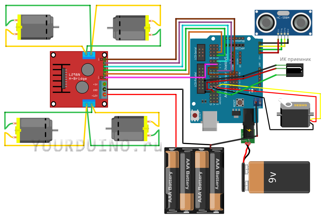
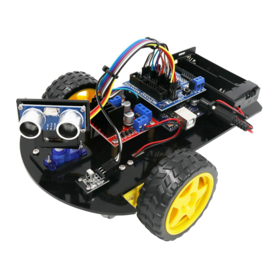
Набор для сборки Smart Car Kit позволит вам собрать полноприводного (4WD) колесного робота на базе Arduino-совместимого контроллера. Управление роботом можно организовать с помощью ИК-сенсора или с использованием Bluetooth модуля. С помощью функциональных модулей, входящих в набор, робот может работать в режиме следования по линии, режиме избегания препятствий, режиме охранной сигнализации и др.
Для сборки вам потребуется только самый простой ручной инструмент, паяльник и немного воображения.
Состав набора:
1) Платформа-основа — 2 шт. (верх, низ);
2) Колесо для робота 66 мм — 4 шт.
3) Мотор-редуктор для робота — 4 шт.
4) Контроллер UNO R3 — 1 шт.
5) Плата расширения Sensor Shield V5.0 — 1 шт.
6) Кабель USB 2.0 (A-B) — 1 шт.
7) Драйвер двигателя L298N — 1 шт.
 Батарейный отсек 6*АА без разъема — 1 шт.
9) Отсек для батарейки «Крона» 9В с разъемом питания — 1 шт.
10) ИК пульт управления (21 кнопка) с батарейкой — 1 шт.
11) Модуль инфракрасного датчика VS1838B — 1 шт.
12) Breadboard mini — 1 шт.
13) Сервопривод SG90 (180 град) или ES08MAII — 1 шт.
14) Кронштейн для сервопривода SG90 и HC-SR04 с крепежом — 1 шт.
15) Датчик линии TCRT5000 4 канала — 2 шт.
16) Bluetooth модуль HC-06 — 1 шт.
17) Ультразвуковой датчик измерения расстояния HC-SR04 — 1 шт.
18) Шлейф из 40 проводов П-П 20см — 1 шт.
19) Шлейф из 40 проводов П-М 20см — 1 шт.
20) Крепления для мотор-редукторов на платформе — 8 шт.
21) Крепеж (стойки М-М M3*30 — 6 шт., винты с потайной головкой M3*30 — 8 шт., винты М3*5 — 12 шт., винты М3*10 — 8 шт., винты М3*8 c потайной головкой -2 шт., винт 2*12 — 4 шт, гайки М3 — 18 шт., гайка М2 — 4 шт.)
Внешний вид деталей может отличаться от представленного на фото.
Пример скетча для колесного робота Smart Car Kit — в данном скетче реализована возможность ручного управления роботом через ИК-канал. А также есть автоматический режим, в котором робот «гуляет» сам, избегая столкновений с препятствиями.
Бумажной инструкции по сборке в комплекте нет.
Инструкция по сборке набора Smart Car.
Смотреть Видео-инструкцию
Инструкция по установке и настройке Arduino_IDE
Для работы робота не забудьте приобрести 4 батарейки АА и 1 батарейку «Крона».
![]() Обратите внимание! Набор представляет собой конструктор и предполагает наличие у пользователя базовых навыков конструирования, программирования и отладки.
Обратите внимание! Набор представляет собой конструктор и предполагает наличие у пользователя базовых навыков конструирования, программирования и отладки.
Набор предполагает самостоятельную сборку управляющего устройства на базе микроконтроллера и набора датчиков с последующим программированием законченного устройства в целях развития и формирования у пользователя инженерного мышления и умений программирования робототехнических систем.
-
Роман 17.04.2019 20:26
хороший магазин качественные товары
Оценка:
СОДЕРЖАНИЕ ►
- Блютуз машинка на Arduino своими руками
- Схема сборки bluethoth машинки на Arduino
- Приложение и код машинки Arduino с Bluethoth
Машинка на Ардуино с Bluetooth управлением от Android телефона — это очень простой, но интересный проект на Arduino UNO с использованием модуля Motor Shield. На этой странице вы узнаете какие потребуются компоненты для изготовления робота машинки на Ардуино своими руками, пошаговую инструкцию по сборке электрической схемы и сможете скачать все необходимые программы для Android и Arduino.
Для этого проекта использовался модуль Motor Shield L293D, два колеса с редукторами, плата Arduino UNO, блютуз модуль HC-05 и два светодиода для фар. Управление происходит дистанционно через Bluetooth сигнал от смартфона или планшета. После сборки модели и установки программ, вы сможете через приложение на смартфоне поворачивать машинкой, ездить вперед и назад, включать и выключать фары.
Машинка на Ардуино своими руками
Для этого проекта потребуется:
- Arduino Uno / Arduino Nano / Arduino Mega;
- Motor Control Shield L293D;
- Bluetooth модуль HC-05/06;
- два мотора с редукторами и колесами;
- аккумулятор 9 Вольт (крона);
- 2 резистора и 2 светодиода;
- корпус и колеса от старой машинки;
- паяльник, термопистолет, провода, припой и т.д.

Схема сборки машинки на Ардуино
Если у вас есть все необходимые детали (в проекте можно обойтись без светодиодов и резисторов), то далее мы рассмотрим, как сделать машинку из ардуино своими руками. Для начала следует припаять к контактам моторчиков провода и зафиксировать их изолентой, чтобы контакты не оторвались. Провода необходимо соединить с клеммниками M1 и M2 на Motor Shield (полярность потом можно будет поменять).

Питание на Bluetooth модуль идет от контактов для сервопривода, в проекте серво нам не понадобятся. А на питание идет стабилизированное напряжение 5 Вольт, что нам подходит. К портам TX и RX удобнее будет припаять коннекторы «мама», а к портам «Pin0» и «Pin1» на Motor Shield припаять штырьки (BLS). Таким образом, вы сможете легко отключать Bluetooth модуль от Arduino при необходимости загрузки скетча.
Управление светодиодами идет от порта «Pin2», здесь провод можно припаять напрямую к порту. Если вы делаете несколько машинок с Блютуз, которыми будете управлять одновременно, то рекомендуем сделать перепрошивку модуля HC-05. Делается прошивка модуля очень просто, а затем вы уже не будете путать машинки, так как у каждой будет отображаться свое уникальное имя на Андроиде.
Приложение и скетч для машинки на Ардуино
После сборки схемы загрузите следующий скетч для машинки (не забудьте отключать Bluetooth модуль от Ардуино при загрузке) и установите приложение на смартфоне. Все файлы для проекта (библиотека AFMotor.h, скетч для машинки и приложение для Android) можно скачать одним архивом по прямой ссылке здесь. Работу скетча можно проверить управлением машинки от компьютера через Serial Monitor по USB.
#include <AFMotor.h>  // подключаем библиотеку для шилда
AF_DCMotor motor1(1); // подключаем мотор к клеммнику M1
AF_DCMotor motor2(2); // подключаем мотор к клеммнику M2

int val; // освобождаем память в контроллере

void setup() {

  Serial.begin(9600);
  pinMode(2, OUTPUT);   // Порт для светодиодов
  motor1.setSpeed(250); // задаем максимальную скорость мотора
  motor1.run(RELEASE);  // останавливаем мотор
  motor2.setSpeed(250); // задаем максимальную скорость мотора
  motor2.run(RELEASE);  // останавливаем мотор
}

void loop() {

if (Serial.available()) // проверяем, поступают ли какие-то команды
  {
    val = Serial.read();

    if (val == 'f') { // едем вперед
motor1.run(FORWARD);
motor1.setSpeed(250);
motor2.run(FORWARD);
motor2.setSpeed(250);
 }

    if (val == 'b') { // едем назад
motor1.run(BACKWARD);
motor1.setSpeed(200);
motor2.run(BACKWARD);
motor2.setSpeed(200);
 }

    if (val == 's') { // останавливаемся
motor1.run(RELEASE);
motor2.run(RELEASE);
 }

    if (val == 'l') { // поворачиваем налево
motor1.run(FORWARD);
motor1.setSpeed(100);
motor2.run(BACKWARD);
motor2.setSpeed(250);
 }

    if (val == 'r') { // поворачиваем направо
motor1.run(BACKWARD);
motor1.setSpeed(250);
motor2.run(FORWARD);
motor2.setSpeed(100);
 }

    if (val == '1') { // включаем светодиоды
digitalWrite(2,HIGH);
 }

    if (val == '0') { // выключаем светодиоды
digitalWrite(2,LOW);
 }

}
}
Пояснения к коду:
- для тестирования, можно отправлять команды с компьютера через USB;
- вращение моторов при подключении к аккумулятору будут отличаться;
- вы можете задавать свою скорость вращения моторами.

После проверки работы машинки, установите приложение на смартфон или планшет. При первом подключении к Bluetooth модулю HC-05/06, потребуется сделать сопряжение с Андроид (затем сопряжение будет выполняться автоматически). Если у вас возникли сложности с подключением — прочитайте эту статью Подключение блютуз модуля к Ардуино или напишите вопрос в комментариях к этой записи.
- Manuals
- Brands
- LAFVIN Manuals
- Robotics
- Obstacle Avoidance Smart Car Kit
- Manual
-
Contents
-
Table of Contents
-
Bookmarks
Quick Links
Obstacle Avoidance Smart Car Kit
Summary of Contents for LAFVIN Obstacle Avoidance Smart Car Kit
-
Page 1
Obstacle Avoidance Smart Car Kit… -
Page 3: Table Of Contents
Content Company Profile…………………………………2 Packing list………………………………….4 Lesson 1 Installing IDE………………………………5 Lesson 2 Add Libraries and Open Serial Monitor……………………….20 Lesson 3 Blink…………………………………. 32 Lesson 4 Installation Method…………………………….43 Lesson 5 Servo………………………………….54 Lesson 6 Ultrasonic Sensor Module…………………………..57 Lesson 7 IR Receiver Module…………………………….62 Lesson 8 L298N Motor Driver…………………………….
-
Page 4: Company Profile
Company Profile Established in 2011, lafvin is a manufacturer and trader specialized in research,development and production of 2560 uno,nano boards,and all kinds of accessories or sensors use for arduino,rasperrry.We also complete starter kits designed for interested lovers of any levels to learn Arduino or Raspberry.We are located in Shenzhen,China.All of our products comply with international quality standards and are…
-
Page 5
Tutorial This tutorial include codes,labraries and lessons. It is designed for beginners. It will teach every users how to assembly the smart robot car kit and use Arduino controller board, sensors and modules. 3/78… -
Page 6: Packing List
Packing list 4/78…
-
Page 7: Lesson 1 Installing Ide
Lesson 1 Installing IDE Introduction The Arduino Integrated Development Environment (IDE) is the software side of the Arduino platform. In this lesson, you will learn how to setup your computer to use Arduino and how to set about the lessons that follow. The Arduino software that you will use to program your Arduino is available for Windows, Mac and Linux.
-
Page 8
STEP2:Download the development software that is compatible with the operating system of your computer. Take Windows as an example here. 6/78… -
Page 9
Click Windows Installer. Click JUST DOWNLOAD. 7/78… -
Page 10
Also version 1.8.0 is available in the material we provided, and the versions of our materials are the latest versions when this course was made. Installing Arduino (Windows) Install Arduino with the exe. Installation package. 8/78… -
Page 11
Click I Agree to see the following interface 9/78… -
Page 12
Click Next You can press Browse… to choose an installation path or directly type in the directory you want. 10/78… -
Page 13
Click Install to initiate installation Finally, the following interface appears, click Install to finish the installation. 11/78… -
Page 14
Next, the following icon appears on the desktop Double-click to enter the desired development environment 12/78… -
Page 15
You may directly choose the installation package for installation and skip the contents below and jump to the next section. But if you want to learn some methods other than the installation package, please continue to read the section. Unzip the zip file downloaded, Double-click to open the program and enter the desired development environment 13/78… -
Page 16
14/78… -
Page 17
However, this installation method needs separate installation of driver. The Arduino folder contains both the Arduino program itself and the drivers that allow the Arduino to be connected to your computer by a USB cable. Before we launch the Arduino software, you are going to install the USB drivers. Plug one end of your USB cable into the Arduino and the other into a USB socket on your computer. -
Page 18
Right-click on the device and select the top menu option (Update Driver Software…). 16/78… -
Page 19
You will then be prompted to either ‘Search Automatically for updated driver software’ or ‘Browse my computer for driver software’. Select the option to browse and navigate to the Xarduino1.8.0drivers. 17/78… -
Page 20
Click ‘Next’ and you may get a security warning, if so, allow the software to be installed. Once the software has been installed, you will get a confirmation message. Windows users may skip the installation directions for Mac and Linux systems and jump to Lesson 1. Mac and Linux users may continue to read this section. -
Page 21
Installing Arduino (Mac OS X) Download and Unzip the zip file, double click the Arduino.app to enter Arduino IDE; the system will ask you to install Java runtime library if you don’t have it in your computer. Once the installation is complete you can run the Arduino IDE. Installing Arduino (Linux) You will have to use the make install command. -
Page 22: Lesson 2 Add Libraries And Open Serial Monitor
Lesson 2 Add Libraries and Open Serial Monitor Installing Additional Arduino Libraries Once you are comfortable with the Arduino software and using the built-in functions, you may want to extend the ability of your Arduino with additional libraries. What are Libraries? Libraries are a collection of code that makes it easy for you to connect to a sensor, display, module, etc.
-
Page 23
Then the library manager will open and you will find a list of libraries that are already installed or ready for installation. In this example we will install the Bridge library. Scroll the list to find it, then select the version of the library you want to install. Sometimes only one version of the library is available. -
Page 24
Finally click on install and wait for the IDE to install the new library. Downloading may take time depending on your connection speed. Once it has finished, an Installed tag should appear next to the Bridge library. You can close the library manager. You can now find the new library available in the Include Library menu. -
Page 25
In the Arduino IDE, navigate to Sketch > Include Library. At the top of the drop down list, select the option to «Add .ZIP Library» You will be prompted to select the library you would like to add. Navigate to the .zip file’s location and open it. -
Page 26
24/78… -
Page 27
Return to the Sketch > Import Library menu. You should now see the library at the bottom of the drop-down menu. It is ready to be used in your sketch. The zip file will have been expanded in the libraries folder in your Arduino sketches directory. NB: the Library will be available to use in sketches, but examples for the library will not be exposed in the File >… -
Page 28
Your Arduino library folder should now look like this (on Windows): DocumentsArduinolibrariesArduinoPartyArduinoParty.cpp My DocumentsArduinolibrariesArduinoPartyArduinoParty.h My DocumentsArduinolibrariesArduinoPartyexamples or like this (on Mac and Linux): Documents/Arduino/libraries/ArduinoParty/ArduinoParty.cpp Documents/Arduino/libraries/ArduinoParty/ArduinoParty.h Documents/Arduino/libraries/ArduinoParty/examples ..There may be more files than just the .cpp and .h files, just make sure they’re all there. (The library won’t work if you put the .cpp and .h files directly into the libraries folder or if they’re nested in an extra folder. -
Page 29
Arduinos and other microcontrollers, they decided to include a serial terminal with the software. Within the Arduino environment, this is called the Serial Monitor. Making a Connection Serial monitor comes with any and all version of the Arduino IDE. To open it, simply click the Serial Monitor icon. 27/78… -
Page 30
Selecting which port to open in the Serial Monitor is the same as selecting a port for uploading Arduino code. Go to Tools -> Serial Port, and select the correct port. Tips: Choose the same COM port that you have in Device Manager. 28/78… -
Page 31
Once open, you should see something like this: 29/78… -
Page 32
Settings The Serial Monitor has limited settings, but enough to handle most of your serial communication needs. The first setting you can alter is the baud rate. Click on the baud rate drop-down menu to select the correct baud rate. (9600 baud) Last, you can set the terminal to Autoscroll or not by checking the box in the bottom left corner. -
Page 33
Pros The Serial Monitor is a great quick and easy way to establish a serial connection with your Arduino. If you’re already working in the Arduino IDE, there’s really no need to open up a separate terminal to display data. Cons The lack of settings leaves much to be desired in the Serial Monitor, and, for advanced serial communications, it may not do the trick. -
Page 34: Lesson 3 Blink
Lesson 3 Blink About this lesson: In this lesson, you will learn how to program your UNO R3 controller board to blink the Arduino’s built-in LED, and how to download programs by basic steps. Principle Fistly,you need to download and intall UNO The UNO R3 board has rows of connectors along both sides that are used to CH340G driver.
-
Page 35
You may find that your UNO R3 board’s ‘L’ LED already blinks when you connect it to a USB plug. This is because the boards are generally shipped with the ‘Blink’ sketch pre-installed. In this lesson, we will reprogram the UNO R3 board with our own Blink sketch and then change the rate at which it blinks. In Lesson 0, you set up your Arduino IDE and made sure that you could find the right serial port for it to connect to your UNO R3 board. -
Page 36
When the sketch window opens, enlarge it so that you can see the entire sketch in the window. 34/78… -
Page 37
The example sketches included with the Arduino IDE are ‘read-only’. That is, you can upload them to an UNO R3 board, but if you change them, you cannot save them as the same file. Since we are going to change this sketch, the first thing you need to do is save your own copy. From the File menu on the Arduino IDE, select ‘Save As..’ and then save the sketch with the name ‘MyBlink’. -
Page 38
You have saved your copy of ‘Blink’ in your sketchbook. This means that if you ever want to find it again, you can just open it using the File > Sketchbook menu option. 36/78… -
Page 39
Attach your Arduino board to your computer with the USB cable and check that the ‘Board Type’ and ‘Serial Port’ are set correctly. 37/78… -
Page 40
Note: The Board Type and Serial Port here are not necessarily the same as shown in picture. If you are using 2560, then you will have to choose Mega 2560 as the Board Type, other choices can be made in the same manner. And the Serial Port displayed for everyone is different, despite COM 26 chosen here, it could be COM3 or COM4 on your computer. -
Page 41
Next, the status will change to ‘Uploading’. At this point, the LEDs on the Arduino should start to flicker as the sketch is transferred. Finally, the staus will change to ‘Done’. The other message tells us that the sketch is using 928 bytes of the 32,256 bytes available.After the ‘Compiling Sketch..’ stage you could get the following error message: 39/78… -
Page 42
It can mean that your board is not connected at all, or the drivers have not been installed (if necessary) or that the wrong serial port is selected. If you encounter this, go back to Lesson 0 and check your installation. Once the upload has completed, the board should restart and start blinking. -
Page 43
gle line comments start with // and everything up until the end of that line is considered a comment. The first line of code is: int led = 13; As the comment above it explains, this is giving a name to the pin that the LED is attached to. This is 13 on most Arduinos, including the UNO and Leonardo. -
Page 44
You are now going to make your LED blink faster. As you might have guessed, the key to this lies in changing the parameter in () for the ‘delay’ command. This delay period is in milliseconds, so if you want the LED to blink twice as fast, change the value from 1000 to 500. This would then pause for half a second each delay rather than a whole second. -
Page 45: Lesson 4 Installation Method
Lesson 4 Installation Method 43/78…
-
Page 46
44/78… -
Page 47
45/78… -
Page 48
46/78… -
Page 49
47/78… -
Page 50
48/78… -
Page 51
49/78… -
Page 52
50/78… -
Page 53
51/78… -
Page 54
52/78… -
Page 55
53/78… -
Page 56: Lesson 5 Servo
About this lesson: In this lesson, you will learn how to control a servo motor using LAFVIN UNO R3. The servo motor has three leads. The color of the leads varies between servo motors, but the red lead is always 5V and GND will either be brown.The red one is the power wire and should be connected to the 5v port and this is usually orange.
-
Page 57
Connection diagram 55/78… -
Page 58
Code After connecting,please open the the program and load up the code — Lesson 5 Servo onto your Arduino board. See Lesson 3 for details about program uploading if there are any errors. Before you can run this, make sure that you have installed the < Servo> library or re-install it, if necessary. Otherwise, your code won’t work. -
Page 59: Lesson 6 Ultrasonic Sensor Module
Lesson 6 Ultrasonic Sensor Module About this lesson: Ultrasonic sensor is great for all kind of projects that need distance measurements, avoiding obstacles as examples. The HC-SR04 is inexpensive and easy to use since we will be using a Library specifically designed for these sensor. Introduction: Ultrasonic sensor module HC-SR04 provides 2cm-400cm non-contact measurement function, the ranging accuracy can reach to 3mm.
-
Page 60
range in proportion .You can calculate the range through the time interval between sending trigger signal and receiving echo signal. Formula: us / 58 = centimeters or us / 148 =inch; or: the range = high level time * velocity (340M/S) / 2; we suggest to use over 60ms measurement cycle, in order to prevent trigger signal to the echo signal. -
Page 61
Wiring diagram 59/78… -
Page 62
Code Using a Library designed for these sensors will make our code short and simple. We include the library at the beginning of our code, and then by using simple commands we can control the behavior of the sensor. After wiring, please open the program in the code folder- Lesson 6 Ultrasonic Sensor Module and click UPLOAD to upload the program. See Lesson 3 for details about program uploading if there are any errors. -
Page 63
Open the monitor then you can see the data as blow: Click the Serial Monitor button to turn on the serial monitor. The basics about the serial monitor are introduced in details in Lesson 1. 61/78… -
Page 64: Lesson 7 Ir Receiver Module
Lesson 7 IR Receiver Module About this lesson: Using an IR Remote is a great way to have wireless control of your project. Infrared remotes are simple and easy to use. In this tutorial we will be connecting the IR receiver to the UNO, and then use a Library that was designed for this particular sensor.
-
Page 65
Wiring diagram 63/78… -
Page 66
Code After wiring, please open the program in the code folder- and click UPLOAD to upload the program. See Lesson3 Lesson 7 IR Receiver Module for details about program uploading if there are any errors. Before you can run this, make sure that you have installed the < IRremote > library or re-install it, if necessary. Otherwise, your code won’t work. -
Page 67
Remote control code: 65/78… -
Page 68: Lesson 8 L298N Motor Driver
Lesson 8 L298N Motor Driver About this lesson: In this lesson, you will learn how to use a L298N Motor Driver module. Component Introduction The L298N actually contains two complete H-Bridge circuits, so it is capable of driving a pair of DC motors. This makes it ideal for robotic projects, as most robots have either two or four powered wheels.
-
Page 69
Using L298N made by ST Company as the control chip, the module has characteristics of strong driving ability, low calorific value and strong anti-interference ability. This module can use built-in 78M05 for electric work via a driving power supply part. But to avoid the damage of the voltage stabilizing chip, please use an external 5V logic supply when using more than 12V driving voltage. -
Page 70
Wiring diagram 68/78… -
Page 71
Code After wiring, please open the program in the code folder- Lesson 8 L298N Motor Driver and click UPLOAD to upload the program. See Lesson 3 for details about program uploading if there are any errors. After connection and power-on, two motors rotate clockwise for 2 second at a speed of 200 (PWM value is 200) and then stop for 2 second; two motors rotate anticlockwise for 2 second at a speed of 100 (PWM value is 100) and then stop for 2second;… -
Page 72: Lesson 9 Ir Remote Control Car
Lesson 9 IR Remote Control Car About this lesson: This lesson ,regarding Arduino microcontroller as main control, uses IR module to receive IR remote signal and send the signal to Arduino. Arduino will analyses the signal and then control the driver motor and the motion of the car with IR remote control. In addition, you can observe the state of the car through 1602 I2C Module.
-
Page 73
Connection Schematic 71/78… -
Page 74
Wiring diagram 72/78… -
Page 75
Code After wiring, please open the program in the code folder- Lesson 9 IR Remote Control Car and click UPLOAD to upload the program. See Lesson 3 for details about program uploading if there are any errors. Before you can run this, make sure that you have installed the < IRremote > library or re-install it, if necessary. Otherwise, your code won’t work. -
Page 76: Lesson 10 Obstacle Avoidance
Lesson 10 Obstacle Avoidance Car About this lesson: This lessom ,regarding Arduino as main control, detect front obstacle by ultrasonic sensor and platform motor, and send the feedback to Arduino. Arduino will analyses the feedback signal and then control the driver motor to adjust the car diversion. Finally the car is able to avoid obstacle automatically and keep going.
-
Page 77
Principle: 1.Ultrasonic detecting distance: one port emits high level more than 10 US. Once it outputting level, open potentiometer to time. When the port becomes low level, read out current value. Use the time of detecting distance to calculate distance. 2.Use ultrasonic to detect the distance between obstacle and car, so that control the motion of the car according to the data. -
Page 78
Connection Schematic 76/78… -
Page 79
Wiring diagram 77/78… -
Page 80
Code After wiring, please open the program in the code folder- and click UPLOAD to upload the program. See Lesson 10 Obstacle Avoidance Car Lesson 2 for details about program uploading if there are any errors. Before you can run this, make sure that you have installed the < Servo> < HC-SR04> library or re-install it, if necessary. Otherwise, your code won’t work.
Время выполнения заказа:
| Quantity (компл.) | 1 — 100 | 101 — 600 | > 600 |
| Примерное время (в днях) | 3 | 8 | Подлежит согласованию |
Сведения о покупке
Защита с помощью
Транспортировка:
Связаться с поставщиком для согласования деталей доставки
Для вас Гарантия своевременной отправки
Платежи:
Шифрование и повышенная безопасность платежей Подробнее
Возврат товаров и возмещение средств
Eligible for refunds within 30 days of receiving products. Подробнее