-
Page 1
EDBCSXA064 .Md4 Operating Instructions ECSEAxxx / ECSDAxxx / ECSCAxxx Axis module ˘ «Application»… -
Page 2
0Fig. 0Tab. 0 © 2013 Lenze Automation GmbH, Hans−Lenze−Str. 1, D−31855 Aerzen No part of this documentation may be reproduced or made accessible to third parties without written consent by Lenze Automa- tion GmbH. All information given in this documentation has been selected carefully and complies with the hardware and software described. -
Page 3
ECSEA_003A EDBCSXA064 EN 3.2… -
Page 4
Scope of supply Position Description Quantity ECSLA… axis module Accessory kit with fixing material corresponding to the design (L): «E» − standard panel−mounted unit «D» − push−through technique «C» − cold−plate technique Mounting Instructions Drilling jig Functional earth conductor (only ECSDA…) Note! The ECSZA000X0B connector set must be ordered separately. -
Page 5: Table Of Contents
…………General safety and application notes for Lenze controllers .
-
Page 6
Contents Mechanical installation ……….. . Important notes . -
Page 7
……. . . Entry of motor data for Lenze motors . -
Page 8
Contents System bus (CAN / CAN−AUX) configuration ……..Setting the CAN node address and baud rate . -
Page 9
Contents Monitoring functions …………10.1 Fault responses . -
Page 10
Contents Troubleshooting and fault elimination ……..12.1 Fault analysis . -
Page 11
Contents 13.10 CAN3_IO (node number 33) ……….13.10.1 Inputs_CAN3 . -
Page 12
Contents 13.20 MCTRL_MotorControl (node number 131) ……. . 13.20.1 Inputs_MCTRL . -
Page 13
Contents Appendix …………..14.1 PLC functionality . -
Page 14: Preface And General Information
The input DIGIN_bIn1_b… Further information … about the conventions used for the Lenze variable identifiers, system blocks, function blocks, and functions can be found in the appendix of the DDS online documentation «Introduction to IEC 61131−3 programming». The compliance with these conventions ensures uniform and universal labelling and makes reading PLC programs easier.
-
Page 15: Terminology Used
(PLC) or further controllers exclusively via the X4 interface. Interface X14 (CAN−AUX) is exclusively used for parameter setting and diagnostics. Drive PLC Developer Studio (Lenze software for PLC programming acc. to IEC 61131) Global Drive Control (Lenze software for parameter setting and diagnostics)
-
Page 16: Code Descriptions
Preface and general information About these Operating Instructions Code descriptions 1.1.3 Code descriptions Lenze codes are described in the form of tables with the following structure: Column Abbreviation Meaning Cxxxx Code no. Cxxxx Subcode 1 of Cxxxx Subcode 2 of Cxxxx…
-
Page 17: Structure Of The System Block Descriptions
Preface and general information About these Operating Instructions Structure of the system block descriptions 1.1.4 Structure of the system block descriptions All system block descriptions contained in this Manual have the same structure: Headline with SB identifier ‚ SB function and node number …
-
Page 18: Features Of The Ecsxa Axis Module
Features of the ECSxA axis module Safety function «safe torque off» (formerly «safe standstill») ƒ PLC programming according to IEC 61131−3 with the Lenze software «Drive PLC ƒ Developer Studio» (DDS) Functions that can be used in your projects are available as system blocks(SB).
-
Page 19: Scope Of Supply
Components for operation and communication ƒ Brake resistors ƒ Mains fuses ƒ Mains chokes ƒ RFI filters ƒ Tip! Information and auxiliary devices related to the Lenze products can be found in the download area at http://www.Lenze.com EDBCSXA064 EN 3.2…
-
Page 20: Legal Regulations
Instructions. The specifications, processes, and circuitry described in these Instructions are for guidance only and must be adapted to your own specific application. Lenze does not take responsibility for the suitability of the process and circuit proposals.
-
Page 21: System Block Introduction
System blocks ˘ principle System block introduction Lenze pursues the principle to describe functions of the controller by means of function blocks (FB). This principle is also described in the standard IEC 61131−3. Functions that you can use in your project as software functionalities, are contained ƒ…
-
Page 22: Node Numbers
Preface and general information System block introduction Node numbers 1.5.2 Node numbers The system blocks feature the following node numbers: Node System block Notes number DIGITAL_IO Digital inputs/outputs ANALOG1_IO Analog input 1 DFIN_IO_DigitalFrequency Digital frequency input DFOUT_IO_DigitalFrequency Digital frequency output System bus (CAN) CAN1_IO CAN2_IO…
-
Page 23: Access Via System Variables
Preface and general information System block introduction Access via system variables 1.5.3 Access via system variables If you have integrated a system block into the system configuration of the DDS, you can use its system variables within your project. You can call up the input assistance in the editors of the DDS via <F2>, among other things listing all the system variables that are provided: In this Manual, the system variables can be retrieved in the system variable table of the corresponding system block.
-
Page 24: Access Via Absolute Addresses
Preface and general information System block introduction Access via absolute addresses 1.5.4 Access via absolute addresses You can also access the inputs and outputs of the system blocks via absolute addresses according to standard IEC 61131−3: For inputs: For outputs: a = node number %IXa.b.c %QXa.b.c…
-
Page 25
Preface and general information System block introduction Definition of the inputs/outputs Example: Use of the system blocks Inputs_Digital and Outputs_Digital Inputs_DIGITAL Outputs_DIGITAL DIGIN_bIn1_b DIGOUT_bOut1_b DIGIN_bIn2_b C0444/1 DIGIN_bIn3_b DIGIN_bIn4_b C0118/1 C0114/1…4 safe torque off C0443 DIGOUT_bRelais_b C0444/2 DIGIN_bCInh_b safe standstill DIGIN_b_safe_standstill_b C0118/2 mP + Imp C0443… -
Page 26: Integrate System Blocks Into Dds
Preface and general information System block introduction Integrate system blocks into DDS 1.5.6 Integrate system blocks into DDS The required system blocks must be explicitly integrated into the project of the DDS via the control configuration. The control configuration is an object in the Resources tab in the Object Organizer. ƒ…
-
Page 27: Signal Types And Scaling
System block introduction Signal types and scaling 1.5.7 Signal types and scaling A signal type can be assigned to most inputs and outputs of the Lenze function blocks/system blocks. The following signal types are distinguished: digital and analog signals ƒ…
-
Page 28: Safety Instructions
Lenze Automation GmbH does not accept any liability for the suitability of the procedures and circuit proposals described. Depending on their degree of protection, some parts of the Lenze controllers ƒ (frequency inverters, servo inverters, DC speed controllers) and their accessory components can be live, moving and rotating during operation.
-
Page 29
Safety instructions General safety and application notes for Lenze controllers Application as directed Controllers are components which are designed for installation in electrical systems or machines. They are not to be used as domestic appliances, but only for industrial purposes according to EN 61000−3−2. -
Page 30
Reduce housing openings and cutouts to a minimum. Lenze controllers may cause a DC current in the PE conductor. If a residual current device (RCD) is used for protection against direct or indirect contact for a controller with three−phase supply, only a residual current device (RCD) of type B is permissible on the… -
Page 31
Safety instructions General safety and application notes for Lenze controllers Safety functions Certain controller versions support safety functions (e.g. «Safe torque off», formerly «Safe standstill») according to the requirements of the EC Directive 2006/42/EC (Machinery Directive). The notes on the integrated safety system provided in this documentation must be observed. -
Page 32: Thermal Motor Monitoring
179 s in the event of a motor with a thermal motor time constant of 5 minutes (Lenze setting C0128), a motor current of 1.5 x I and a trigger threshold of 100 %.
-
Page 33: Forced Ventilated Or Naturally Ventilated Motors
C0120 (OC6) or C0127 (OC8). Read release time in the diagram Diagram for detecting the release times for a motor with a thermal motor time constant of 5 minutes (Lenze setting C0128): L [%] = 1 × I = 3 ×…
-
Page 34: Self−Ventilated Motors
C0129/x. Parameter setting The following codes can be set for I x t monitoring: Code Meaning Value range Lenze setting C0066 Display of the I x t load of the motor 0 … 250 % − C0120 Threshold: Triggering of error «OC6″…
-
Page 35
Safety instructions Thermal motor monitoring Self−ventilated motors Calculate release time and I x t load Calculate the release time and the I x t load of the motor considering the values in C0129/1 and C0129/2(evaluation coefficient «y»). Formulae for release time Information Release time of the I x t monitoring… -
Page 36: Residual Hazards
ECSxE supply module and the input current ƒ limitation is activated depending on the DC−bus voltage (C0175 = 1 or 2). the axis module is not supplied via a supply module delivered by Lenze. ƒ the low−voltage supply (24 V) is switched off.
-
Page 37
Motor protection Only use motors with a minimum insulation resistance of û = 1.5 kV, ƒ min. du/dt = 5 kV/ms. – Lenze motors meet these requirements. When using motors with an unknown insulation resistance, please contact your ƒ motor supplier. -
Page 38: Safety Instructions For The Installation According To Ul
Safety instructions Safety instructions for the installation according to UL Safety instructions for the installation according to UL Warnings! General markings: Use 60/75 °C or 75 °C copper wire only. ƒ Maximum ambient temperature 55 °C, with reduced output current. ƒ…
-
Page 39: Notes Used
Safety instructions Notes used Notes used The following pictographs and signal words are used in this documentation to indicate dangers and important information: Safety instructions Structure of safety instructions: Danger! (characterises the type and severity of danger) Note (describes the danger and gives information about how to prevent dangerous situations) Pictograph and signal word Meaning…
-
Page 40: Technical Data
Technical data General data and operating conditions Technical data General data and operating conditions Standards and operating conditions Conformity Low−Voltage Directive (2006/95/EG) Approvals UL 508C Power Conversion Equipment Underwriter Laboratories (File No. E132659) CSA 22.2 No. 14 for USA and Canada Max.
-
Page 41
Technical data General data and operating conditions General electrical data Compliance with the requirements acc. to EN 61800−3 Noise emission Compliance with the limit class C2 acc. to EN 61800−3 (achieved by using collective filters typical for the application) Noise immunity Requirements acc. -
Page 42: Rated Data
Technical data Rated data Rated data Axis module Rated data Type ECSxL004 ECSxL008 ECSxL016 Output power 400 V mains [kVA] rated Data for operation with upstream power supply module mains on mains voltage DC−bus voltage 15 … 770 DC−bus DC−bus current DC−bus Rated output current at 4 kHz (causes a heatsink temperature of 70°C at an ambient…
-
Page 43
Technical data Rated data Rated data Type Axis module ECSxL032 ECSxL048 ECSxL064 Output power 400 V mains [kVA] 11.2 13.2 rated Data for operation with upstream power supply module mains on mains voltage DC−bus voltage 15 … 770 DC−bus DC−bus current 15.6 12.5 20.9… -
Page 44: Current Characteristics
Technical data Current characteristics Increased continuous current depending on the control factor Current characteristics 3.3.1 Increased continuous current depending on the control factor In the lower speed range ˘ the motor does not need the full motor voltage ˘ particularly the more powerful ECS axis modules can be permanently operated with increased output ^ 42).
-
Page 45
Technical data Current characteristics Increased continuous current depending on the control factor The following table shows the connections between mains voltage, DC−bus voltage and motor voltage: Mains voltage DC−bus voltage Output voltage (motor voltage) nominally achievable for 100 % x 1.35] mains mains modulation… -
Page 46
Technical data Current characteristics Increased continuous current depending on the control factor Example: The ECS axis module suitable for operation in conjunction with a Lenze motor of type MCS 14L32 is to be determined. Rated motor data ƒ – Rated motor torque (M ) = 17.2 Nm… -
Page 47: Device Protection By Current Derating
Technical data Current characteristics Device protection by current derating 3.3.2 Device protection by current derating The maximum output current is limited. With output frequencies < 5 Hz the limitation depends on the heatsink temperature. ‚ 1.00 1.00 Iout ≤ 70 °C Imax …
-
Page 48: Mechanical Installation
– Ensure unimpeded ventilation of cooling air and outlet of exhaust air. – Several modules of the ECS series can be installed in the control cabinet next to each other without any clearance. The mounting plate of the control cabinet ƒ…
-
Page 49: Mounting With Fixing Rails (Standard Installation)
Mechanical installation Mounting with fixing rails (standard installation) Dimensions Mounting with fixing rails (standard installation) 4.2.1 Dimensions Note! Mounting with ECSZS000X0B shield mounting kit: Mounting clearance below the module > 195 mm ƒ ECSxA005 Fig. 4−1 Dimensions for «panel−mounted» design Axis module Dimensions [mm] Type…
-
Page 50: Mounting Steps
Mechanical installation Mounting with fixing rails (standard installation) Mounting steps 4.2.2 Mounting steps How to install the axis module: 1. Prepare the fixing holes on the mounting surface. – Use the drilling jig for this purpose. 2. Take the fixing rails from the accessory kit in the cardboard box. 3.
-
Page 51: Mounting With Thermal Separation (Push−Through Technique)
Mechanical installation Mounting with thermal separation (push−through technique) Mounting with thermal separation (push−through technique) For the push−through technique the rear panel of the control cabinet must be a steel plate with a thickness of at least 2 mm. The edges of the mounting cutout and the fixing holes for the clamps must be slightly curved inwards (towards the axis module).
-
Page 52: Dimensions
Mechanical installation Mounting with thermal separation (push−through technique) Dimensions 4.3.1 Dimensions Note! Mounting with ECSZS000X0B shield mounting kit: Mounting clearance below the module > 195 mm ƒ ECSXA007 Fig. 4−2 Dimensions for «push−through design» Mounting cutout (a1 x b1), ^ 53 Axis module Dimensions [mm] Type…
-
Page 53
Mechanical installation Mounting with thermal separation (push−through technique) Dimensions Dimensions of mounting cutout Note! Installation with shield mounting ECSZS000X0B: Clearance below the mounting cutout > 220 mm ƒ ECSXA063 Fig. 4−3 Dimensions of mounting cutout Mounting surface Mounting cutout for size 0 Mounting cutout for size 1 Axis module Dimensions [mm]… -
Page 54: Mounting Steps
Mechanical installation Mounting with thermal separation (push−through technique) Mounting steps 4.3.2 Mounting steps How to mount the axis module: 1. Prepare the fixing holes for the wire clamps on the mounting area. For this purpose, apply a drilling jig. 2. Prepare the mounting cutout. The edges of the mounting cutout and the fixing holes for the wire clamps have to be slightly arched inwardly (to the axis module).
-
Page 55: Mounting In Cold−Plate Design
Mechanical installation Mounting in cold−plate design Mounting in cold−plate design The axis modules ECSC… are intended for mounting in cold−plate design (e.g. on collective coolers). Requirements for collective coolers The following requirements must be met to ensure a safe operation of the axis modules: Good thermal contact with the cooler ƒ…
-
Page 56: Dimensions
Mechanical installation Mounting in cold−plate design Dimensions 4.4.1 Dimensions Note! Mounting with ECSZS000X0B shield mounting kit: Mounting clearance below the module > 195 mm ƒ ECSXA009 Fig. 4−5 Dimensions for «cold−plate design» Axis module Dimensions [mm] Type Size ECSC ECSC 88,5 ECSC ECSC…
-
Page 57: Mounting Steps
Mechanical installation Mounting in cold−plate design Mounting steps 4.4.2 Mounting steps À Á Â ECSXA030 Fig. 4−6 Mounting for «cold−plate design» Proceed as follows to mount the axis module: 1. Prepare the fixing holes on the mounting plate. – Use a drilling jig for this purpose. 2.
-
Page 58: Electrical Installation
Electrical installation Installation according to EMC (installation of a CE−typical drive system) Electrical installation Installation according to EMC (installation of a CE−typical drive system) General information The electromagnetic compatibility of a machine depends on the type of installation ƒ and care taken.Especially consider the following: –…
-
Page 59
Electrical installation Installation according to EMC (installation of a CE−typical drive system) Assembly Connect the ECS modules, RFI filters, and mains choke to the earthed mounting ƒ plate with a surface as large as possible: – Mounting plates with conductive surfaces (zinc−coated or stainless steel) allow for permanent contact. -
Page 60
Electrical installation Installation according to EMC (installation of a CE−typical drive system) Shielding Connect the motor cable shield to the axis module ƒ – with the ECSZS000X0B shield mounting kit. – extensively to the mounting plate below the axis module. –… -
Page 61: Power Terminals
Electrical installation Power terminals Power terminals ECSXA080 Fig. 5−1 Plug connectors for power terminals Danger! Dangerous voltage The leakage current to earth (PE) is > 3.5 mA AC or > 10 mA DC. Possible consequences: Death or severe injuries when the device is touched in the event of a fault. ƒ…
-
Page 62
Electrical installation Power terminals All power connections are plug connections and coded. The ECSZA000X0B plug ƒ connector set must be ordered separately. Installation of the cables to EN 60204−1. ƒ The cables used must comply with the approvals required at the site of use (e.g. VDE, ƒ… -
Page 63
Electrical installation Power terminals Shielded cables The following factors decisively determine the effect of the shielded cables: Good shield connection ƒ – Ensure a contact surface as large as possible Low shield resistance ƒ – Only use shields with tin−plated or nickel−plated copper braids (shields with steel braids cannot be used). -
Page 64: Connection To The Dc Bus (+Ug, −Ug)
Electrical installation Power terminals Connection to the DC bus (+U , −U 5.2.1 Connection to the DC bus (+U , −U Stop! No device protection for DC bus voltage surges In passive axis modules (without 24 V−supply), the charging circuit can be overloaded through DC bus voltage surges.
-
Page 65
Power terminals Connection to the DC bus (+U , −U Fuses Mains fuses are not included in the Lenze delivery program. Use standard fuses. ƒ When using ECSxE power supply modules which are fused on the supply side the ƒ… -
Page 66: Connection Plan For Mimimum Wiring With Internal Brake Resistor
Electrical installation Power terminals Connection plan for mimimum wiring with internal brake resistor 5.2.2 Connection plan for mimimum wiring with internal brake resistor Documentation of the ECSxE power supply module Observe the enclosed notes. Stop! Always operate the ECS power supply modules with a brake resistor (internal/external).
-
Page 67
Electrical installation Power terminals Connection plan for mimimum wiring with internal brake resistor F1…F3 » » L3 PE +UG +UG +UG +UG ECSEE… ECSxS/P/M/A… ECSxS/P/M/A… ECSDE… BD1 BD2 U V W PE BD1 BD2 U V W PE » » «… -
Page 68: Connection Plan For Mimimum Wiring With External Brake Resistor
Electrical installation Power terminals Connection plan for mimimum wiring with external brake resistor 5.2.3 Connection plan for mimimum wiring with external brake resistor Documentation of the ECSxE power supply module Observe the enclosed notes. Stop! Always operate the ECS power supply modules with a brake resistor. ƒ…
-
Page 69
Electrical installation Power terminals Connection plan for mimimum wiring with external brake resistor F1…F3 » » L3 PE +UG +UG +UG +UG ECSxE… ECSxS/P/M/A… ECSxS/P/M/A… BD1 BD2 U V W PE BD1 BD2 U V W PE » » » «… -
Page 70: Motor Connection
) when using synchronous motors or according to the rated motor current ) for asynchronous motors. Length of the unshielded ends: 40 … 100 mm (depending on the cable cross−section) ƒ Lenze system cables meet these requirements. ƒ Use the ECSZS000X0B shield mounting kit for EMC−compliant wiring. ƒ…
-
Page 71: Motor Holding Brake Connection
Electrical installation Power terminals Motor holding brake connection 5.2.5 Motor holding brake connection The motor holding brake is connected to X25/BD1 and X25/BD2. ƒ is supplied with low voltage via the terminals X6/B+ and X6/B−: ƒ +23 … +30 V DC, max.1.5 A Stop! Protect X6/B+ with an F 1.6 A fuse.
-
Page 72
1.5 V is produced. The voltage drop can be compensated by a higher voltage at the cable entry. The voltage required at X6/B+ and X6/B− for the Lenze system cables is calculated as follows: [V] + U [V] ) 0.08… -
Page 73: Connection Of An Ecsxk
Electrical installation Power terminals Connection of an ECSxK… capacitor module (optional) 5.2.6 Connection of an ECSxK… capacitor module (optional) The ECS capacitor modules support the DC−bus voltage for the drive system. These capacitor module types are available: ECSxK001 (705 mF, ±20 %) ƒ…
-
Page 74: Control Terminals
Electrical installation Control terminals Control terminals ECSXA070 Fig. 5−7 Plug connectors for control terminals (X6) For the supply of the control electronics an external 24 V DC voltage at terminals X6/+24 and X6/GND is required. Stop! The control cables must always be shielded to prevent interference ƒ…
-
Page 75
Electrical installation Control terminals Shield connection of control cables and signal cables The plate on the front of the device serves as the mounting place (two threaded holes M4) for the shield connection of the signal cables. The screws used may extend into the inside of the device by up to 10 mm. -
Page 76
(central controller enable) of the power supply module via the relay 0. – In the default Lenze setting of the ECS axis modules, DO1 is set to «ready». «Ready» is only present if a specified DC−bus voltage has been reached. -
Page 77
Electrical installation Control terminals Assignment of the plug connectors Plug connector X6 Terminal Function Electrical data X6/+24 Low−voltage supply of the control electronics 20 … 30 V DC, 0. A (max. 1 A) for starting current of 24 V: X6/GND Reference potential of low−voltage supply max. -
Page 78: Digital Inputs And Outputs
Electrical installation Control terminals Digital inputs and outputs 5.3.1 Digital inputs and outputs Stop! If an inductive load is connected to X6/DO1, a spark suppressor with a limiting function to max. 50 V ± 0 % must be provided. GNDext DI1 DI2 DI3 DI4 «…
-
Page 79: Analog Input
Electrical installation Control terminals Analog input 5.3.2 Analog input » » ECSXA015 Fig. 5−10 Analog input at X6 » HF−shield termination by large−surface connection to functional earth (see Mounting Instructions for ECSZS000X0B shield mounting kit) Analog input configuration Use C0034 to set whether the input is to be used for a master voltage (±10 V) or a ƒ…
-
Page 80: Safe Torque Off
Electrical installation Control terminals Safe torque off 5.3.3 Safe torque off The axis modules support the «safe torque off» safety function (formerly «safe standstill»), «protection against unexpected start−up», in accordance with the requirements of EN ISO 13849−1, Performance Level Pld. For this purpose, the axis modules are equipped with two independent safety paths.
-
Page 81
Electrical installation Control terminals Safe torque off 5.3.3.2 Functional description The «safe torque off» state can be initiated any time via the input terminals X6/SI1 (controller enable/inhibit) and X6/SI2 (pulse enable/inhibit). For this purpose a LOW level has to be applied at both terminals: X6/SI1 = LOW (controller inhibited): ƒ… -
Page 82
Electrical installation Control terminals Safe torque off 5.3.3.3 Important notes Danger! When using the «safe torque off» function, additional measures are required for «emergency stops»! There is neither an electrical isolation between motor and axis module nor a «service» or «repair switch». Possible consequences: Death or severe injuries ƒ… -
Page 83
Electrical installation Control terminals Safe torque off 5.3.3.4 Technical data Terminal assignment Plug connector X6 Terminal Function Level Electrical data X6/S24 Low−voltage supply 18 … 30 V DC 0.7 A X6/SO «Safe torque off» feedback During operation 24 V DC output 0.7 A (max. -
Page 84
Electrical installation Control terminals Safe torque off 5.3.3.5 Function check After installation the operator must check the «safe torque off» function. ƒ The function check must be repeated at regular intervals, after one year at the ƒ latest. Stop! If the function check leads to impermissible states at the terminals, commissioning cannot take place! Test specifications Check the circuitry with regard to correct function. -
Page 85
Electrical installation Control terminals Safe torque off 5.3.3.6 Example: Wiring with electronic safety switching device «Pilz PNOZ e1vp» for Performance Level Pl 24V DC Start ECSxS/P/M/A Not-Halt/ Emergency stop Pilz PNOZ e1vp 10s 24V DC Pilz 774195 Pilz 774195 ECSXA034 Fig. -
Page 86
PL in accordance with EN ISO 13849−1 or SIL 2 in accordance with EN 62061 are to be used in all upstream applications! Interconnection examples can be found in the download area (Application Knowledge Base) at: www.Lenze.com EDBCSXA064 EN 3.2… -
Page 87
Electrical installation Control terminals Safe torque off 5.3.3.7 Example: Wiring with electromechanical safety switching device «Siemens 3TK2827» for Performance Level Pl Not-Halt/ Emergency stop 24V DC Siemens 3TK2827 ECSxS/P/M/A Start ECSXA035 Fig. 5−13 Example: Wiring with «Siemens 3TK2827» safety switching device T1 Test key 1 T2 Test key 2 The motor is shut down in accordance with stop category 1 of EN 60204 when the… -
Page 88
PL in accordance with EN ISO 13849−1 or SIL 2 in accordance with EN 62061 are to be used in all upstream applications! Interconnection examples can be found in the download area (Application Knowledge Base) at: www.Lenze.com EDBCSXA064 EN 3.2… -
Page 89: Automation Interface (Aif)
Electrical installation Automation interface (AIF) Automation interface (AIF) The keypad XT or a communication module can be attached to or removed from the automation interface (X1). This is also possible during operation. The keypad XT serves to enter and visualise parameters and codes. ƒ…
-
Page 90: Wiring Of System Bus (Can)
MotionBus (CAN) with master control ECS_COB007 Fig. 5−15 MotionBus (CAN) with controller as master MotionBus (CAN), interface X4 System bus (CAN), interface X14 Master Slave PC with the Lenze parameter setting and operating software (GDC, GDL, GDO) HMI / operating unit EDBCSXA064 EN 3.2…
-
Page 91
Electrical installation Wiring of system bus (CAN) ECS_COB003 Fig. 5−16 Bus connections on the controller Assignment of the plug connectors X4 (CAN) X14 (CAN−AUX) Description CAN−HIGH CAN−LOW Reference potential Specification of the transmission cable We recommend the use of CAN cables in accordance with ISO 11898−2: CAN cable in accordance with ISO 11898−2 Cable type Paired with shielding… -
Page 92
Electrical installation Wiring of system bus (CAN) System bus (CAN) wiring ECS_COB004 Fig. 5−17 Example: System bus (CAN) wiring via interface X4 ECS axis module Master control, e.g. ETC Note! Connect one bus terminating resistor (120 W) each to the first and last node of the system bus (CAN). -
Page 93
Electrical installation Wiring of system bus (CAN) Bus cable length Note! The permissible cable lengths must be observed. 1. Check the compliance with the total cable length in Tab. 5−1. The baud rate determines the total cable length. CAN baud rate [kbit/s] Max. -
Page 94
It is not possible to use a cable length of 450 m without using a repeater. After 360 m (point 2) a repeater must be installed. Result The Lenze repeater type 2176 is used (cable reduction: 30 m) Calculation of the maximum cable length: First segment: 360 m Second segment: 360 m (according to Tab. -
Page 95: Wiring Of The Feedback System
(e.g. by using separating webs or separated trailing cables) is not ensured on the entire cable length cable due to an installation on the system side, the encoder cable must be provided with an insulation resistance of 300 V. Lenze encoder cables meet this requirement.
-
Page 96: Resolver Connection
Wiring of the feedback system Resolver connection 5.6.1 Resolver connection Note! Use the prefabricated Lenze system cables for the connection of a resolver. ƒ Cable length: max. 50 m ƒ Depending on the cable length and resolver used parameterise the code ƒ…
-
Page 97: Encoder Connection
Electrical installation Wiring of the feedback system Encoder connection 5.6.2 Encoder connection Danger! Valid when using an operating software up to and including V7.0: When absolute value encoders are used, uncontrolled movements of the drive are possible! If an absolute value encoder is disconnected from the axis module during operation, the fault OH3−TRIP occurs.
-
Page 98
Electrical installation Wiring of the feedback system Encoder connection Incremental encoder (TTL encoder) Features Input/output frequency: 0 … 200 kHz Current consumption: 6 mA per channel Current on output V (X8/pin 4): Max. 200 mA < 50 m R1 (+KTY) R2 (-KTY) ECSXA026 Fig. -
Page 99
Electrical installation Wiring of the feedback system Encoder connection SinCos encoders and SinCos absolute value encoders with Hiperface Features Input/output frequency: 0 … 200 kHz 221 W Internal resistance (R Offset voltage for signals SIN, COS, Z: 2.5 V The differential voltage between signal track and reference track must not exceed ƒ… -
Page 100: Digital Frequency Input/Output (Encoder Simulation)
Electrical installation Wiring of the feedback system Digital frequency input/output (encoder simulation) 5.6.3 Digital frequency input/output (encoder simulation) The digital frequency coupling of ECSxS/P/A axis modules basically is effected as a master−slave connection via the interface X8. This interface can either be used as a digital frequency input or as a digital frequency output (e.
-
Page 101
Electrical installation Wiring of the feedback system Digital frequency input/output (encoder simulation) 2 to 3 slaves connected to the master: ƒ Use the EMF2132IB digital frequency distributor to wire the ECS axis modules with master digital frequency cable EYD0017AxxxxW01W01 and slave digital frequency cable EYD0017AxxxxW01S01. -
Page 102: Commissioning
Before you start Commissioning Before you start Note! The use of a Lenze motor is assumed in this description of the ƒ commissioning steps. For details on the operation with other motors see ^ 132. The description is based on operation with the Lenze programs «Drive PLC ƒ…
-
Page 103: Commissioning Steps (Overview)
Commissioning Commissioning steps (overview) Commissioning steps (overview) Start Create a new project with the Drive PLC Developer Studio (DDS) and load it into the ECSxA… axis module DDS Manuals: – Introduction in the IEC 61131−3 programming – Getting started – Reference Manual Make the basic settings using the parameter setting program Global Drive Control (GDC).
-
Page 104: Carrying Out Basic Settings With Gdc
^ 112 Set feedback system. Set Lenze motors with resolvers (standard) in the GDC parameter menu under Short setup W Feedback system. Set other resolvers and encoders in the GDC parameter menu under Motor/feedback systems W Feedback system.
-
Page 105
Commissioning Carrying out basic settings with GDC Settings Brief description Detailed information Select Terminal I/O W Digital inputs/outputs in the GDC ^ 129 10. Set the polarity of the digital inputs and outputs. parameter menu: C0114/x (polarity of dig. inputs X6/DI1 … DI4) C0118/1 (polarity of dig. -
Page 106: Loading The Lenze Setting
Loading the Lenze setting Loading the Lenze setting Note! When loading the Lenze setting, all parameters are reset to the basic setting defined by Lenze. Settings that have been adjusted before get lost during this process! In GDC, you can find the parameters and codes to be set in the parameter menu under Load / Save / PLC / Multitasking.
-
Page 107: Setting Of Mains Data
Therefore, set C0175 = 3 for the axis modules (charging current limitation inactive, charging resistor short−circuited). If the Lenze setting has been loaded via C0002, C0175 = 3 must be reset. Cyclic switching of the mains voltage at the power supply module can ƒ…
-
Page 108: Setting The Voltage Thresholds
[V AC] [V DC] [V DC] yes/no yes/no 400 … 460 yes/no yes/no C0174 C0174 + 5 V 400 (Lenze setting) yes/no C0174 C0174 + 5 V 400 … 460 yes/no C0174 C0174 + 5 V C0174 C0174 + 5 V…
-
Page 109: Entry Of Motor Data For Lenze Motors
The following only describes the parameter setting for Lenze motors! (If you ƒ use a motor from another manufacturer, see ^ 132.) If the Lenze setting has been loaded via C0002, the motor data must be ƒ re−entered. The freely available «GDC−Easy» does not provide the «Input assistant for ƒ…
-
Page 110
Commissioning Entry of motor data for Lenze motors ECSXA302 Fig. 6−5 GDC view: Motor selection 3. Select the connected motor from the list (see motor nameplate). – The corresponding motor data is displayed in the «Motor data» fields on the right. -
Page 111: Holding Brake Configuration
Commissioning Holding brake configuration Holding brake configuration Tip! If you use a motor without a holding brake, you can skip this chapter. In GDC, you can find the parameters and codes to be set in the parameter menu under Complete code list. Code Name Description…
-
Page 112: Setting Of The Feedback System For Position And Speed Control
The GDC contains the parameters or codes to be set in the parameter menu under Motor/Feedb. W Feedback: Fig. 6−6 GDC view: Commissioning of the feedback system Note! If the Lenze setting has been loaded via C0002, the feedback system must be reset. EDBCSXA064 EN 3.2…
-
Page 113: Resolver As Position And Speed Encoder
Absolute value encoder (multi−turn) at ^ 138 C0058 Rotor diff −90.0 Rotor displacement angle (offset angle) Input in case of Lenze motor with resolver: −90° hiperface absolute value encoder: 0° Code value is adapted by the rotor position adjustment function (C0095).
-
Page 114
Commissioning Setting of the feedback system for position and speed control Resolver as position and speed encoder Code Possible settings IMPORTANT Designation Lenze/ Selection {Appl.} ^ 138 [C0095] Rotor pos adj Activation of rotor position adjustment for automatic determination of the rotor displacement angle. -
Page 115: Ttl/Sincos Encoder As Position And Speed Encoder
Commissioning Setting of the feedback system for position and speed control TTL/SinCos encoder as position and speed encoder 6.8.2 TTL/SinCos encoder as position and speed encoder If a TTL incremental encoder or a sin/cos encoder without serial communication is connected to X8 and used for position and speed control, the following setting sequence must be observed: 1.
-
Page 116
^ 331 [C0419] Enc. setup Encoder selection ^ 115 Selection of encoder type ^ 122 indicated on the nameplate of the Lenze motor. The encoder data (C0420, C0421, C0427) is set automatically in accordance with the selection. Common IT512−5V Incremental encoder with TTL level IT1024−5V… -
Page 117
Commissioning Setting of the feedback system for position and speed control TTL/SinCos encoder as position and speed encoder Code Possible settings IMPORTANT Designation Lenze/ Selection {Appl.} (multi−turn) AM256−8V Selections 407, 408, 409 are only possible with operating system AM512−8V 7.0 or higher. -
Page 118: Ttl/Sincos Encoder As Position Encoder And Resolver As Speed Encoder
Commissioning Setting of the feedback system for position and speed control TTL/SinCos encoder as position encoder and resolver as speed encoder 6.8.3 TTL/SinCos encoder as position encoder and resolver as speed encoder A TTL incremental encoder connected to X8 or a SinCos encoder without serial communication can be configured as a position encoder with a resolver connected to X7 being used as a speed encoder.
-
Page 119
Selection {Appl.} ^ 138 C0058 Rotor diff −90.0 Rotor displacement angle (offset angle) Input in case of Lenze motor with resolver: −90° hiperface absolute value encoder: 0° Code value is adapted by the rotor position adjustment function (C0095). Only relevant for the operation of synchronous motors. -
Page 120
^ 331 [C0419] Enc. setup Encoder selection ^ 115 Selection of encoder type ^ 122 indicated on the nameplate of the Lenze motor. The encoder data (C0420, C0421, C0427) is set automatically in accordance with the selection. Common IT512−5V Incremental encoder with TTL level IT1024−5V… -
Page 121
Setting of the feedback system for position and speed control TTL/SinCos encoder as position encoder and resolver as speed encoder Code Possible settings IMPORTANT Designation Lenze/ Selection {Appl.} ^ 331 [C0420] Encoder const. Number of increments of the ^ 115… -
Page 122: Absolute Value Encoder As Position And Speed Encoder
Commissioning Setting of the feedback system for position and speed control Absolute value encoder as position and speed encoder 6.8.4 Absolute value encoder as position and speed encoder Danger! Valid when using an operating software up to and including V7.0: When absolute value encoders are used, uncontrolled movements of the drive are possible! If an absolute value encoder is disconnected from the axis module during…
-
Page 123
When configuring the absolute value encoder, an «SD7» system error is activated. The error can only be reset by means of mains switching. Codes for feedback system selection Code Possible settings IMPORTANT Designation Lenze/ Selection {Appl.} ^ 112 [C0490] Feedback pos Selection of feedback system for positioning control… -
Page 124
^ 331 [C0419] Enc. setup Encoder selection ^ 115 Selection of encoder type ^ 122 indicated on the nameplate of the Lenze motor. The encoder data (C0420, C0421, C0427) is set automatically in accordance with the selection. Common IT512−5V Incremental encoder with TTL level IT1024−5V… -
Page 125: Absolute Value Encoder As Position Encoder And Resolver As Speed Encoder
Commissioning Setting of the feedback system for position and speed control Absolute value encoder as position encoder and resolver as speed encoder 6.8.5 Absolute value encoder as position encoder and resolver as speed encoder Danger! Valid when using an operating software up to and including V7.0: When absolute value encoders are used, uncontrolled movements of the drive are possible! If an absolute value encoder is disconnected from the axis module during…
-
Page 126
Do not parameterise codes C0420, C0421 and C0427! ƒ 4. Save settings with C0003 = 1. Codes for feedback system selection Code Possible settings IMPORTANT Designation Lenze/ Selection {Appl.} ^ 112 [C0490] Feedback pos Selection of feedback system for positioning control Resolver at X7… -
Page 127
Selection {Appl.} ^ 138 C0058 Rotor diff −90.0 Rotor displacement angle (offset angle) Input in case of Lenze motor with resolver: −90° hiperface absolute value encoder: 0° Code value is adapted by the rotor position adjustment function (C0095). Only relevant for the operation of synchronous motors. -
Page 128
^ 331 [C0419] Enc. setup Encoder selection ^ 115 Selection of encoder type ^ 122 indicated on the nameplate of the Lenze motor. The encoder data (C0420, C0421, C0427) is set automatically in accordance with the selection. Common IT512−5V Incremental encoder with TTL level IT1024−5V… -
Page 129: Setting The Polarity Of Digital Inputs And Outputs
Terminal I/O: Fig. 6−7 GDC view: Setting of the polarity of digital inputs and outputs Code Possible settings IMPORTANT Designation Lenze/ Selection {Appl.} ^ 129 C0114 Polarity of the digital inputs 1 DIGIN pol HIGH level active…
-
Page 130: Entry Of Machine Parameters
Commissioning Entry of machine parameters 6.10 Entry of machine parameters In GDC the codes for machine parameters such as maximum speed and ramp times can be found in the parameter menu under: Short setup ƒ Fig. 6−8 GDC view: Machine parameters EDBCSXA064 EN 3.2…
-
Page 131: Controller Enable (Cinh = 0)
Commissioning Controller enable (CINH = 0) 6.11 Controller enable (CINH = 0) The controller will only be enabled internally if no signal sources relevant for the controller inhibit (CINH) are activated (i.e. CINH−signal sources = 0). The following table shows the signal sources for controller enable: Source for controller Controller Controller…
-
Page 132: Operation With Motors From Other Manufacturers
Motor/feedback systemsW W Motor adjustment. Fig. 6−9 GDC view: Manual setting of the motor data Code Possible settings IMPORTANT Designation Lenze/ Selection {Appl.} [C0006] Op mode Operating mode of the motor control If the master pulse (via MCTRL: C0911 = 0 or DfIn:…
-
Page 133
Selection {Appl.} ^ 138 C0058 Rotor diff −90.0 Rotor displacement angle (offset angle) Input in case of Lenze motor with resolver: −90° hiperface absolute value encoder: 0° Code value is adapted by the rotor position adjustment function (C0095). Only relevant for the operation of synchronous motors. -
Page 134
Commissioning Operation with motors from other manufacturers Entering motor data manually Code Possible settings IMPORTANT Designation Lenze/ Selection {Appl.} C0111 Service Code Fine adjustment − rotor resistance 50.00 {1 %} 199.99 C0112 Service Code Fine adjustment − rotor time constant… -
Page 135: Checking The Direction Of Rotation Of The Motor Feedback System
CW direction (view on the front of the motor shaft), the numerical value must rise. If the values are falling, reverse the Sin+ and Sin− connections. Code Possible settings IMPORTANT Designation Lenze/ Selection {Appl.} ^ 135 C0060 Rotor pos Current rotor position; value is derived from position encoder.
-
Page 136: Adjusting Current Controller
This is why the default current controller settings of the «GDC motor data input assistant» can usually be used. A current controller adjustment is only required for third−party motors and for Lenze motors only in special cases.
-
Page 137
Commissioning Operation with motors from other manufacturers Adjusting current controller Leakage inductance and stator resistance of the motor are not known: The current controller can be optimised metrologically with a current probe and an oscilloscope. For this, a test mode is available in which the current C0022 x Ö2 flows in phase U after controller enable. -
Page 138: Effecting Rotor Position Adjustment
Commissioning Operation with motors from other manufacturers Effecting rotor position adjustment 6.12.4 Effecting rotor position adjustment Note! Resolver / absolute value encoder with Hiperface® interface If the rotor zero phase is not known, the rotor position only has to be ƒ…
-
Page 139
Commissioning Operation with motors from other manufacturers Effecting rotor position adjustment Setting sequence 1. Inhibit controller. (^ 131) – Press the <F9> key in GDC. – Green LED is blinking, red LED is off 2. Unload motor mechanically. – Separate the motor from the gearbox or machine so that it can rotate freely. 3. -
Page 140
Selection {Appl.} ^ 138 C0058 Rotor diff −90.0 Rotor displacement angle (offset angle) Input in case of Lenze motor with resolver: −90° hiperface absolute value encoder: 0° Code value is adapted by the rotor position adjustment function (C0095). Only relevant for the operation of synchronous motors. -
Page 141: Optimising The Drive Behaviour After Start
The speed controller can only be set correctly when the system constellation has ƒ been completed. The current controller is set correctly (given with a Lenze motor and setting via ƒ motor data input assistant in the GDC) . The PE connection of the axis module is sufficient so that the actual values are not ƒ…
-
Page 142
= MCTRL_nNAdapt_a [%] × C0070 – Default: MCTRL_nNAdapt_a = 100 % ð V = 100 % × C0070 = C0070 Code Possible settings IMPORTANT Designation Lenze/ Selection {Appl.} ^ 141 C0070 Vp speedCTRL Proportional gain of speed controller (V 0.00 { 0.01}… -
Page 143
Commissioning Optimising the drive behaviour after start Speed controller adjustment Signal limitation If the drive operates with the maximum torque, the speed controller operates ƒ within the limitation. The drive cannot follow the speed setpoint. ƒ MCTRL_bMMax_b is set to TRUE. ƒ… -
Page 144: Adjustment Of Field Controller And Field Weakening Controller
Commissioning Optimising the drive behaviour after start Adjustment of field controller and field weakening controller 6.13.2 Adjustment of field controller and field weakening controller Stop! Field weakening operation is only possible with asynchronous motors. ƒ The available torque is reduced by the field weakening. ƒ…
-
Page 145
Commissioning Optimising the drive behaviour after start Adjustment of field controller and field weakening controller 6.13.2.1 Adjusting the field controller The field controller settings depend on the motor data. Setting sequence 1. Stop the PLC program: C2108 = 2 – As of operating system version 7.0 (see nameplate), this is no longer necessary, because C0006 (see 2.) can also be written when the PLC program is running! 2. -
Page 146
Commissioning Optimising the drive behaviour after start Adjustment of field controller and field weakening controller 6.13.2.2 Field weakening controller adjustment The field weakening controller determines the speed performance of the ƒ asynchronous motor in the field weakening range. The field weakening controller can only be set correctly when the system ƒ… -
Page 147: Resolver Adjustment
Commissioning Optimising the drive behaviour after start Resolver adjustment 6.13.3 Resolver adjustment When adjusting the resolver, mainly component tolerances of the resolver evaluation are compensated in the device. No resolver error characteristic is accepted. The resolver adjustment is only required if the speed behaviour is irregular despite optimised settings of the speed and position control loop.
-
Page 148: Parameter Setting
Parameter setting General information Parameter setting General information Controllers and power supply modules can be adapted to your application by setting ƒ the parameters. A detailed description of the functions can be found in the chapter «Commissioning» (¶ 102). The parameters for the functions are stored in numbered codes: ƒ…
-
Page 149: Parameter Setting With «Global Drive Control» (Gdc)
Parameter setting with «Global Drive Control» (GDC) Parameter setting with «Global Drive Control» (GDC) With the «Global Drive Control» (GDC) parameterisation and operating program, Lenze provides a plain, concise and compatible tool for the configuration of your application−specific drive task with the PC or laptop: The GDC input assistant offers a comfortable motor selection.
-
Page 150: Parameter Setting With The Xt Emz9371Bc Keypad
Parameter setting Parameter setting with the XT EMZ9371BC keypad Connecting the keypad Parameter setting with the XT EMZ9371BC keypad The keypad is available as accessories. A complete description is given in the documentation on the keypad. 7.3.1 Connecting the keypad …
-
Page 151: Description Of The Display Elements
Power outputs inhibited Adjusted current limitation is exceeded in motor mode or generator mode Speed controller 1 within its limitation Drive is torque−controlled Only active for operation with Lenze devices of the 9300 series! Active fault 1 Parameter acceptance Display…
-
Page 152
4 Number Active level Meaning Explanation Menu level Menu number Display is only active when operating Lenze devices of the 8200 vector or 8200 motec series. No menu for ECSxE power supply module Code level Four−digit code number 5 Number… -
Page 153: Description Of The Function Keys
Inhibit the controller, LED in the key lights up. Reset fault (TRIP reset): 1. Remove cause of malfunction 2. Press S 3. Press U No menu for ECSxE power supply module Only active when operating Lenze devices of the 8200 vector or 8200 motec series. EDBCSXA064 EN 3.2…
-
Page 154: Changing And Saving Parameters
Parameter setting Parameter setting with the XT EMZ9371BC keypad Changing and saving parameters 7.3.4 Changing and saving parameters All parameters for the axis module/power supply module parameterisation or monitoring are stored in codes. The codes are numbered and marked with a «C» in the documentation. Some codes store the parameters in numbered «subcodes»…
-
Page 155: System Bus (Can / Can−Aux) Configuration
System bus (CAN / CAN−AUX) configuration Setting the CAN node address and baud rate System bus (CAN / CAN−AUX) configuration The codes for the system bus (CAN / CAN−AUX) configuration can be found in the GDC parameter menu under System bus. They are divided into separate code ranges: Interface Code range System bus (CAN)
-
Page 156: Settings Via Dip Switch
System bus (CAN / CAN−AUX) configuration Setting the CAN node address and baud rate Settings via DIP switch 8.1.1 Settings via DIP switch ECS_COB005 Fig. 8−1 DIP switch for node address and baud rate (all switches: OFF) Node address setting The node address is set by means of switches 2 …
-
Page 157
System bus (CAN / CAN−AUX) configuration Setting the CAN node address and baud rate Settings via DIP switch Baud rate setting Note! The baud rate must be set identically for all CAN nodes. Switch Baud rate [kbit/s] 1000 EDBCSXA064 EN 3.2… -
Page 158: Settings Via Codes
S1 usually apply. The baud rate (C0351/C2451) must be set identically for all CAN bus nodes. ƒ If the Lenze setting has been loaded via C0002, ƒ – C0351/C2451 is set = 0 (500 kbits; – you have to reset the baud rate (C0351/C2451) and the CAN node address (C0350/C2450).
-
Page 159
System bus (CAN / CAN−AUX) configuration Setting the CAN node address and baud rate Settings via codes Code Possible settings IMPORTANT Designation Lenze/ Selection {Appl.} ^ 156 C2451 CANa baud Baud rate for CAN bus interface rate X14 (CAN−AUX) 500 kBit/s… -
Page 160: Individual Addressing
To make the alternative node address valid, set the corresponding subcode of C0353/C2453 = 1. CAN interface Code Value The addresses are defined by C0353/1 C0350 (Lenze setting) C0354/1 for CAN1_IN C0354/2 for CAN1_OUT C0353/2 C0350 (Lenze setting) X4 (CAN) C0354/3 for CAN2_IN…
-
Page 161
System bus (CAN / CAN−AUX) configuration Individual addressing Code Possible settings IMPORTANT Designation Lenze/ Selection {Appl.} ^ 160 C0354 Alternative node address for CAN_IN/CAN_OUT (CAN bus interface X4) 1 CAN addr. 512 Address 2 CAN1_IN 2 CAN addr. Address 2 CAN1_OUT 3 CAN addr. -
Page 162: Determining The Boot−Up Master For The Drive System
NMT−state «Operational» by the master. A data exchange via the process data objects can only be effected in this state. Use C0352/C2452 for configuration. Code Possible settings IMPORTANT Designation Lenze/ Selection {Appl.} ^ 162 C0352 CAN mst Boot−up master/slave configuration for CAN bus…
-
Page 163: Setting The Boot−Up Time/Cycle Time
After the boot−up time has elapsed, the NMT telegram for initialising the CAN network is sent by the boot−up master and the process data transfer is started. Only valid if C0352/C2452 = 1 (master). ƒ Normally the Lenze setting (3000 ms) is sufficient. ƒ State change from «Pre−operational» to «Operational» ƒ…
-
Page 164
System bus (CAN / CAN−AUX) configuration Setting the boot−up time/cycle time Code Possible settings IMPORTANT Designation Lenze/ Selection {Appl.} ^ 163 C2456 CAN time settings for CAN bus interface X14 (CAN−AUX) 1 CANa times 3000 {1 ms} 65000 CAN−AUX boot−up time:… -
Page 165: Reset Node
(fieldbus scan). Code Possible settings IMPORTANT Designation Lenze/ Selection {Appl.} ^ 279 C0358 Reset node Make a reset node for the CAN bus node.
-
Page 166: Axis Synchronisation (Can Synchronisation)
«Drive PLC Developer Studio» (DDS) must not only comprise the SB CAN_Synchronization (¶ 281) but also the SB DIGITAL_IO. (¶ 343) Code Possible settings IMPORTANT Designation Lenze/ Selection {Appl.} ^ 166 C1120 Sync mode Sync signal source ^ 170…
-
Page 167
Always set the synchronisation phase higher than the maximum possible «jitter» of the received CAN sync telegrams! phase shifting and thus periodic changes of signal frequencies are called «Jitter». Code Possible settings IMPORTANT Designation Lenze/ Selection {Appl.} ^ 167 C1122 Sync phase 0.460 Synchronisation phase 0.000 {0.001 ms}… -
Page 168
CAN sync identifiers The transmit and receive identifiers of the sync telegram can be configured via the following codes: Code Possible settings IMPORTANT Designation Lenze/ Selection {Appl.} ^ 168 C0367 Sync Rx ID CAN sync receipt ID for CAN bus interface X4… -
Page 169: Monitoring Of The Synchronisation (Sync Time Slot)
The amount of the jitter has an impact on the parameterisation of the «time slot». The variable CAN_bSyncInsideWindow_b can be used to monitor the synchronisation. Code Possible settings IMPORTANT Designation Lenze/ Selection {Appl.} ^ 169 C1123 Sync window 0.010 Synchronisation window 0.000…
-
Page 170: Axis Synchronisation Via Can
Connect «CANSync−InsideWindow» with digital output. C1120 = 1 Active synchronisation by sync telegram via CAN bus. C0366 = 1 (Lenze setting) CAN sync reaction: Slaves respond to sync telegram. Master Define the telegram (identifier) sequence: A . Send new setpoint to all slaves.
-
Page 171: Axis Synchronisation Via Terminal X6/Di1
X6/DI1. Slaves C1120 = 2 Synchronisation through sync signal via terminal X6/DI1 (DigIn_bIn1_b) is active. Slaves C0366 = 1 (Lenze setting) CAN sync reaction: Slaves respond to sync telegram. Master Start communication/send sync signals. Slaves Read C0362 from the master.
-
Page 172: Node Guarding
Node Life Time + Node Guard Time (C0382) @ Node Life Time Factor (C0383) 4. Set the response to a «Life Guarding Event» via C0384. Code Possible settings IMPORTANT Designation Lenze/ Selection {Appl.} ^ 162 C0352 CAN mst Boot−up master/slave…
-
Page 173
System bus (CAN / CAN−AUX) configuration Node guarding Code Possible settings IMPORTANT Designation Lenze/ Selection {Appl.} ^ 172 C0384 Err Node Guarding (slave) NodeGuard Response for the occurrence of a NodeGuard−Event Only relevant for setting C0352 = 4. TRIP Message Warning FAIL−QSP… -
Page 174: Can Management
System bus (CAN / CAN−AUX) configuration CAN management CAN management /CANaux_Management The system block CAN_Management serves to activate a reset node to e.g. accept changes in the transfer rate and ƒ addressing. serves to process statuses as Communication Error, Bus Off State, etc. in the PLC ƒ…
-
Page 175: Mapping Indices To Codes
LenzeCanDSxDrv.lib. By means of this driver, indices of the ECSxA… axis modules and other Lenze PLCs can be assigned to another code than the one that is assigned automatically.
-
Page 176
4101 3200 4101 3200 4101 3200 20000 3000 20000 3000 Code access: C3200/5 Lenze code = 24575 — Index = 24575 — 21475 = 3100 Code access = C3100/1 Fig. 8−3 Redirection process of indices to codes EDBCSXA064 EN 3.2… -
Page 177: Diagnostics Codes
System bus (CAN / CAN−AUX) configuration Diagnostics codes CAN bus status (C0359/C2459) 8.10 Diagnostics codes The following diagnostic codes serves to follow the process of the CAN communication via the interfaces X4 (CAN, C03xx) and X14 (CAN−AUX, C24xx): C0359/C2459: Bus state ƒ…
-
Page 178: Can Telegram Counter (C0360/2460)
System bus (CAN / CAN−AUX) configuration Diagnostics codes CAN telegram counter (C0360/2460) 8.10.2 CAN telegram counter (C0360/2460) C0360/2460 counts for all parameter data channel the telegrams which are valid for the controller. The counters have a width of 16 bits. If the value «65535» is exceeded, counting restarts with «0».
-
Page 179: Can Bus Load (C0361/2461)
System bus (CAN / CAN−AUX) configuration Diagnostics codes CAN bus load (C0361/2461) 8.10.3 CAN bus load (C0361/2461) Use C0361/C2461 to determine the bus load through the controller or the individual data channels in percent. Faulty telegrams are not considered. Bus load of the individual subcodes: C0361/C2461 Meaning Subcode 1…
-
Page 180: Remote Parameterisation (Gateway Function)
Note! The SDO gateway cannot be used to read out codes >C2000 or codes of the Inverter Drives 8400 and Servo Drives 9400. Code Possible settings IMPORTANT Designation Lenze/ Selection {Appl.} ^ 180 [C0370] SDO gateway Activate address gateway/remote parameterisation The SDO gateway cannot be used to read out codes >C2000…
-
Page 181
System bus (CAN / CAN−AUX) configuration Remote parameterisation (gateway function) Code Possible settings IMPORTANT Designation Lenze/ Selection {Appl.} ^ 202 C0603 MONIT CE5 Fault response − gateway ^ 180 function monitoring (CE5) «Timeout» when remote parameter setting (C0370) is activated via interface X4 (CAN) -
Page 182: Configuring The Aif Interface (X1)
In order that communication can be established via the system bus, all nodes must use the same baud rate for the data transmission. The baud rate is configured via code C2351: Code Possible settings IMPORTANT Designation Lenze/ap Selection ^ 182 C2351 XCAN baud Baud rate XCAN rate (AIF interface X1)
-
Page 183: Can Boot Up (Aif)
Operationalis not executed by a higher−level host system (PLC), a controller can be intended for a «quasi» master to execute this task. The configuration is done via code C2352: Code Possible settings IMPORTANT Designation Lenze/ap Selection ^ 183 C2352 XCAN mst Establish XCAN master operation. (AIF interface X1)
-
Page 184: Node Address (Node Id)
(AIF interface X1) Assignment of the node address for the data exchange between Lenze devices If Lenze devices are assigned with node addresses in a complete ascending order, the identifiers of the event−controlled data objects (XCAN2_IO/XCAN3_IO) are factory−set so that the devices are able to communicate with each other:…
-
Page 185: Identifiers Of The Process Data Objects
AIF interface (X1) configuration Identifiers of the process data objects Identifiers of the process data objects The identifiers for the process data objects XCAN1_IO … XCAN3_IO consist of the basic identifiers and the node address set in C2350: Identifier = basic identifier + node address Object Basic identifier PDO1…
-
Page 186: Individual Identifier Assignment
C2350: 1. Set C2353/x to «1». – (x = Subcode of the corresponding process data object): Code Possible settings IMPORTANT Designation Lenze/ap Selection ^ 185 C2353 Source for system bus node addresses of XCAN_IN/XCAN_OUT…
-
Page 187: Display Of The Identifier Set
Display of the identifier set 9.4.2 Display of the identifier set The identifier which is set for the process data objects can be displayed via C2355. Code Possible settings IMPORTANT Designation Lenze/ap Selection ^ 187 C2355 Identifier for XCAN_IN/XCAN_OUT (AIF interface X1) Read only…
-
Page 188: Cycle Time (Xcan1_Out
C2356/x = 0 The output data is always transferred when one value in the eight bytes of user data ƒ has changed (Lenze default setting). Time−controlled transmission C2356/x = 1 … 65000 The output data is transferred with the cycle time set in C2356/x (referred to the ƒ…
-
Page 189
AIF interface (X1) configuration Cycle time (XCAN1_OUT … XCAN3_OUT) Code for activating the transmission of event−controlled PDOs Code Possible settings IMPORTANT Designation Lenze/ap Selection C2364 Event−controlled PDO transmission (AIF interface X1) Send PDOs when changing to «Operational» state Do not send PDOs… -
Page 190: Synchronisation
9.6.1 XCAN sync response The response to the receipt of a sync telegram can be configured via C2375: Code Possible settings IMPORTANT Designation Lenze/ap Selection C2375 TX mode for XCANx_OUT (AIF interface X1) 1 XCAN Tx Response to sync XCAN1_OUT…
-
Page 191: Xcan Sync Tx Transmission Cycle
The cycle time required for transmitting a sync telegram with the identifier set in C2368 can be configured via C2356/5: Code Possible settings IMPORTANT Designation Lenze/ap Selection ^ 188 C2356 Time settings for XCAN (AIF interface X1) 1 XCAN times {1 ms} 65000 XCAN boot−up time:…
-
Page 192: Monitoring
For the inputs of the process data objects XCAN1_IN … XCAN3_IN a time monitoring can be configured via C2357: Code Possible settings IMPORTANT Designation Lenze/ap Selection ^ 192 C2357 Monitoring time for XCAN process data input objects (AIF interface X1) Only ECSxA: When the subcodes 1 …
-
Page 193: Bus Off
If the ECSxA… axis module has been decoupled from the system bus due to too many faulty received telegrams, the signal «BusOffState» (CE14) is set. The response to this can be configured via C2382/4 Code Possible settings IMPORTANT Designation Lenze/ap Selection C2382 The XCAN monitoring is configured if no telegrams have been received. (AIF interface X1) 1 XCAN Conf.
-
Page 194
AIF interface (X1) configuration Monitoring Codes for heartbeat Code Possible settings IMPORTANT Designation Lenze/ap Selection C2369 XCAN Consumer Heartbeat COB−ID (AIF interface X1) C2370 XCAN Heartbeat time setting (AIF interface X1) {1 ms} 65535 Consumer heartbeat time {1 ms} 65535 Producer heartbeat time… -
Page 195: Operating Status Of Aif Interface
Operating status of AIF interface Operating status of AIF interface C2121 serves to display the operating status of the AIF interface X1: Code Possible settings IMPORTANT Designation Lenze/ap Selection ^ 195 C2121 AIF:State AIF status More detailed information can be found in the documentation of the plugged−in fieldbus…
-
Page 196: Monitoring Functions
Monitoring functions Monitoring functions Different monitoring functions (¶ 198) protect the drive system from impermissible operating conditions. If a monitoring function responds, the set fault response is triggered to protect the drive and ƒ the fault message is entered position 1 in the fault history buffer (C0168/x, in case ƒ…
-
Page 197: Fault Responses
Monitoring functions Fault responses 10.1 Fault responses ð Consequence Response Display Keypad XT Fail TRIP TRIP active: ð The power outputs U, V, W are switched to high resistance. ð The drive is coasting (no control). TRIP reset: ð The drive decelerates to its setpoint within the set deceleration times.
-
Page 198: Overview Of Monitoring Functions
10.2 Overview of monitoring functions Monitoring Possible fault responses l Lenze setting ü Can be set Fault message Description Source Code TRIP Message Warning Fail−QSP x071 System fault Internal ü ü ü ü x091 External monitoring (activated via DCTRL) C0581…
-
Page 199
Monitoring Possible fault responses l Lenze setting ü Can be set Fault message Description Source Code TRIP Message Warning Fail−QSP ü ü x126 CE15 Communication error of the gateway function via CAN bus at interface X14 CANaux C2485 (CAN−AUX) C0371 = 1: Gateway channel X14 (CAN−AUX) C2470: Selection of the CANaux object for L_ParRead and L_ParWrite ü… -
Page 200
Monitoring Possible fault responses l Lenze setting ü Can be set Fault message Description Source Code TRIP Message Warning Fail−QSP ü ü x085 Master current value encoder error on analog input X6/AI+, AI− (C0034 = 1) MCTRL C0598 x087 Absolute value encoder initialisation error at X8 MCTRL ü… -
Page 201
Monitoring Possible fault responses l Lenze setting ü Can be set Fault message Description Source Code TRIP Message Warning Fail−QSP 0072 Check sum error in parameter set 1 Internal 0074 Program error Internal 0075 Error in the parameter sets Internal… -
Page 202: Configuring Monitoring Functions
Each process data input object can monitor whether a telegram has been received within a specified time. As soon as a telegram arrives, the corresponding monitoring time (C0357/C02457) is restarted («retriggerable monoflop» function). Code Possible settings IMPORTANT Designation Lenze/ Selection {Appl.} ^ 202 C0357 Monitoring time for CAN1…3_IN (CAN bus interface X4)
-
Page 203
Monitoring functions Configuring monitoring functions Monitoring times for process data input objects Code Possible settings IMPORTANT Designation Lenze/ Selection {Appl.} ^ 202 C2457 Monitoring time for CANaux1…3_IN (CAN bus interface X14) 1 CE monit time 3000 {1 ms} 65000 CE11 monitoring time… -
Page 204: Time−Out Monitoring For Activated Remote Parameterisation
If remote parameterisation is activated (gateway function (¶ 180)) and a timeout occurs, the system error message CE5/CE15 is output. The response to this can be configured via C0603/C2485. Code Possible settings IMPORTANT Designation Lenze/ Selection {Appl.} ^ 202 C0603 MONIT CE5 Fault response − gateway ^ 180 function monitoring (CE5) «Timeout»…
-
Page 205: Short Circuit Monitoring (Oc1)
Monitoring functions Configuring monitoring functions Short circuit monitoring (OC1) 10.3.3 Short circuit monitoring (OC1) Fault message Monitoring function System variable Possible response TRIP Messag Warnin · Short circuit MCTRL_bShortCircuit_b · Default setting üSetting possible The monitoring process is activated if a short circuit occurs in the motor phases. This can also be caused by an interturn fault in the machine.
-
Page 206: Motor Temperature Monitoring (Oh3, Oh7)
Note! This monitoring function only applies to temperature sensors specified by Lenze like the ones used on standard Lenze servo motors. With regard to default setting, this monitoring is switched actively and is actuated when no Lenze servo motor is used! The motor temperature is monitored by means of a continuous KTY temperature sensor.
-
Page 207
Monitoring functions Configuring monitoring functions Motor temperature monitoring (OH3, OH7) Code Possible settings IMPORTANT Designation Lenze/ Selection {Appl.} ^ 206 C0583 MONIT OH3 Fault response − monitoring of motor temperature (fixed temperature threshold). Detection through KTY thermal sensor via resolver input X7 or encoder input X8. -
Page 208: Heatsink Temperature Monitoring (Oh, Oh4)
Furthermore, it is possible to activate e.g. additional fans which would generate an unacceptable noise nuisance when operated continuously. Code Possible settings IMPORTANT Designation Lenze/ Selection {Appl.} ^ 208 C0122 OH4 limit Threshold for heatsink temperature monitoring {1 °C}…
-
Page 209: Monitoring Of Internal Device Temperature (Oh1, Oh5)
Furthermore, for instance, additional fans can be activated, generating a noise load when switched to continuous operation. Code Possible settings IMPORTANT Designation Lenze/ Selection {Appl.} ^ 209 C0124 OH5 limit Threshold for temperature monitoring inside the device 90 C0062 >…
-
Page 210: Function Monitoring Of Thermal Sensors (H10, H11)
If the thermal sensors report values outside the measuring range, fault H10 (heatsink) or H11 (interior) is reported. The response to these faults can be defined under C0588. Code Possible settings IMPORTANT Designation Lenze/ Selection {Appl.} ^ 210 C0588 MONIT Fault response − monitoring H10/H11 Thermal sensors in the controller.
-
Page 211: Current Load Of Controller (I X T Monitoring: Oc5, Oc7)
(^ 212). The response to exceeding the adjustable threshold can be defined under C0604. Code Possible settings IMPORTANT Designation Lenze/ Selection {Appl.} ^ 205 C0123 OC7 limit Threshold for I x t warning (axis module) 100 C0064 > C0123 ð fault message…
-
Page 212
Monitoring functions Configuring monitoring functions Current load of controller (I x t monitoring: OC5, OC7) Overcurrent characteristic TRIP ECSxS/P/M/A064 ECSxS/P/M/A048 ECSxS/P/M/A004, -008, -016, -032 I / I ECSXA025 Overcurrent characteristic ECSxA…, see also Rated data ^ 42 Fig. 10−1 The overcurrent characteristic shows the maximum time t till the axis module TRIP generates an I x t error. -
Page 213
10 s @ 200 % ) 50 s @ 44 % + 70 % 60 s The current device utilisation is displayed in C0064: Code Possible settings IMPORTANT Designation Lenze/ Selection {Appl.} C0064 Utilization Device utilisation (I x t) over the last 180 s Only display {1 %} C0064 >… -
Page 214: Current Load Of Motor (I2 X T Monitoring: Oc6, Oc8)
179 s in the event of a motor with a thermal motor time constant of 5 minutes (Lenze setting C0128), a motor current of 1.5 x I and a trigger threshold of 100 %.
-
Page 215
C0120 (OC6) or C0127 (OC8). Read release time in the diagram Diagram for detecting the release times for a motor with a thermal motor time constant of 5 minutes (Lenze setting C0128): L [%] = 1 × I = 3 ×… -
Page 216
C0129/x. Parameter setting The following codes can be set for I x t monitoring: Code Meaning Value range Lenze setting C0066 Display of the I x t load of the motor 0 … 250 % − C0120 Threshold: Triggering of error «OC6″… -
Page 217
Monitoring functions Configuring monitoring functions Current load of motor (I x t monitoring: OC6, OC8) Calculate release time and I x t load Calculate the release time and the I x t load of the motor considering the values in C0129/1 and C0129/2(evaluation coefficient «y»). -
Page 218: Dc−Bus Voltage Monitoring (Ou, Lu)
Monitoring functions Configuring monitoring functions DC−bus voltage monitoring (OU, LU) 10.3.11 DC−bus voltage monitoring (OU, LU) Fault message Monitoring function System variable Possible response TRIP Messag Warnin · Overvoltage MCTRL_bOvervoltage_b · Undervoltage MCTRL_bUndervoltage_b · Default setting üSetting possible These monitoring functions monitor the DC bus and protect the controller. If the DC−bus voltage at terminals +U and −U exceeds the upper switch−off…
-
Page 219
[V AC] [V DC] [V DC] yes/no yes/no 400 … 460 yes/no yes/no C0174 C0174 + 5 V 400 (Lenze setting) yes/no C0174 C0174 + 5 V 400 … 460 yes/no C0174 C0174 + 5 V C0174 C0174 + 5 V… -
Page 220
Monitoring functions Configuring monitoring functions DC−bus voltage monitoring (OU, LU) Code Possible settings IMPORTANT Designation Lenze/ Selection {Appl.} ^ 107 C0173 UG limit Adaptation of the DC−bus voltage thresholds: Check during commissioning and adapt, if necessary. All drive components in DC bus connections must have the same thresholds. -
Page 221: Voltage Supply Monitoring − Control Electronics (U15)
ƒ Reset fault message 1. Check motor cables. 2. Carry out TRIP−RESET. Code Possible settings IMPORTANT Designation Lenze/ Selection {Appl.} ^ 221 C0597 MONIT LP1 Fault response − monitoring of motor phase failure (LP1) When this function is activated, the calculating time provided for…
-
Page 222: Monitoring Of The Resolver Cable (Sd2)
The same applies if «warning» is set as a response. For commissioning C0586, always use the Lenze setting (TRIP). ƒ Only use the possibility of disconnection via C0586 if the monitoring is ƒ…
-
Page 223: Motor Temperature Sensor Monitoring (Sd6)
−50 … +250 °C. If the values are outside this measuring range, monitoring is activated. The response is set via C0594. Code Possible settings IMPORTANT Designation Lenze/ Selection {Appl.} ^ 223 C0594 MONIT SD6 Fault response − monitoring KTY sensor for the motor temperature.
-
Page 224: Monitoring Of The Absolute Value Encoder Initialisation (Sd7)
Monitoring functions Configuring monitoring functions Monitoring of the absolute value encoder initialisation (Sd7) 10.3.16 Monitoring of the absolute value encoder initialisation (Sd7) Fault message Monitoring function System variable Possible response TRIP Messag Warnin · Absolute value encoder MCTRL_bEncoderFault_b initialisation error ·…
-
Page 225: Sin/Cos Signal Monitoring (Sd8)
SD8 trip being released immediately. The «Sd8» fault message can only be reset by mains switching. ƒ Code Possible settings IMPORTANT Designation Lenze/ Selection {Appl.} ^ 225 C0580 Monit SD8 Fault response − monitoring of SinCos signals at X8…
-
Page 226: Monitoring Of The Speed System Deviation (Nerr)
Please observe that the system deviation reaches higher values under ƒ normal operating conditions with short ramp times. Code Possible settings IMPORTANT Designation Lenze/ Selection {Appl.} ^ 226 C0576 nErr tolerance Tolerance window for the speed system deviation referring to…
-
Page 227: Monitoring Of Max. System Speed (Nmax)
If the actual speed value encoder fails, it is not provided that this monitoring ƒ will be activated. The max. system speed can be set via C0596. Code Possible settings IMPORTANT Designation Lenze/ Selection {Appl.} ^ 227 C0596 NMAX limit 5500 Maximum system speed {1 rpm} 16000 EDBCSXA064 EN 3.2…
-
Page 228: Monitoring Of The Rotor Position Adjustment (Pl)
Monitoring functions Configuring monitoring functions Monitoring of the rotor position adjustment (PL) 10.3.20 Monitoring of the rotor position adjustment (PL) Fault message Monitoring function System variable Possible response TRIP Messag Warnin · Fault during rotor position MCTRL_bRotorPositionFault_b adjustment · Default setting üSetting possible This monitoring function observes the correct execution of the rotor position adjustment.
-
Page 229: Diagnostics
Diagnostics Diagnostics with Global Drive Control (GDC) Diagnostics 11.1 Diagnostics with Global Drive Control (GDC) In GDC, the codes for drive system diagnostics can be found in the parameter menu under Diagnostic and the corresponding submenus. Fault history values can be found in the Fault history menu.
-
Page 230: Diagnostics With Global Drive Oscilloscope (Gdo)
11.2 Diagnostics with Global Drive Oscilloscope (GDO) The «Global Drive Oscilloscope» (GDO) is included in the scope of supply of the Lenze parameter setting and operating program «Global Drive Control» (GDC) and the «Drive PLC Developer Studio» (DDS) and can be used as an additional diagnostic program.
-
Page 231: Gdo Buttons
Diagnostics Diagnostics with Global Drive Oscilloscope (GDO) GDO buttons 11.2.1 GDO buttons Clicking on the corresponding button executes the respective function. Press the <F1> key to call the HTML online help. Symbol bar at the top (‚, Fig. 11−2) Symbol Function (button) Connect device…
-
Page 232: Diagnostics With The Xt Emz9371Bc Keypad
Diagnostics Diagnostics with the XT EMZ9371BC keypad 11.3 Diagnostics with the XT EMZ9371BC keypad In the «Diagnostic» menu the two submenus «Actual info» and «History» contain all codes monitoring the drive ƒ fault/error diagnosis ƒ In the operating level, more status messages are displayed. If several status messages are active, the message with the highest priority is displayed.
-
Page 233: Diagnostics With Pcan−View
Diagnostics Diagnostics with PCAN−View Monitoring of telegram traffic on the CAN bus 11.4 Diagnostics with PCAN−View «PCAN−View» is the basic version of the «PCAN−Explorer» program for Windows® of PEAK System Technik GmbH. The program permits a simultaneous transmission and reception of CAN messages which can be transmitted manually and periodically.
-
Page 234
Diagnostics Diagnostics with PCAN−View Monitoring of telegram traffic on the CAN bus On the basis of the IDs displayed, you can assign the telegrams to the devices. If no telegrams are displayed, this may be caused by various factors: Is your Engineering PC connected to the correct CAN bus? ƒ… -
Page 235: Setting All Can Nodes To The «Operational» Status
Diagnostics Diagnostics with PCAN−View Setting all CAN nodes to the «Operational» status 11.4.2 Setting all CAN nodes to the «Operational» status How to set all CAN nodes to the «Operational» status: 1. Create the following CAN message under «New transmit message»: 2.
-
Page 236: Troubleshooting And Fault Elimination
Troubleshooting and fault elimination Fault analysis Fault analysis via the LED display Troubleshooting and fault elimination Failures can be quickly detected by means of display elements or status messages via the system bus (CAN/CAN−AUX). Display elements and status messages provide a rough classification of the trouble. In the chapter «12.3.2 Causes and remedies»…
-
Page 237
Troubleshooting and fault elimination Fault analysis Fault analysis with the history buffer 12.1.3 Fault analysis with the history buffer The history buffer (C0168) enables you to trace faults. The corresponding fault messages are stored in eight memory locations in the sequence of their occurrence. Structure of the history buffer The fields under «fault history»… -
Page 238
Fault analysis with the history buffer Reset fault message The current fault message can be reset via a TRIP−RESET (e.g. via C0043): Code Possible settings IMPORTANT Designation Lenze/ Selection {Appl.} ^ 254 C0043 Trip reset Reset active fault message (TRIP−RESET) Reset fault message (TRIP−RESET) / no… -
Page 239: Fault Analysis Via Lecom Status Words (C0150/C0155)
Fault analysis via LECOM status words (C0150/C0155) 12.1.4 Fault analysis via LECOM status words (C0150/C0155) The LECOM status words (C0150/C0155) are coded as follows: Code Possible settings IMPORTANT Designation Lenze/ Selection {Appl.} ^ 328 C0150 Status word Device status word 1 (DCTRL) ^ 239 Read only 65535 Controller evaluates information as 16 bits (binary−coded)
-
Page 240
Troubleshooting and fault elimination Fault analysis Fault analysis via LECOM status words (C0150/C0155) Code Possible settings IMPORTANT Designation Lenze/ Selection {Appl.} C0155 Status word 2 Status word 2 (advanced status word) Display only 65535 Controller interprets information as 16 bit (binary coded) -
Page 241: Malfunction Of The Drive
Troubleshooting and fault elimination Malfunction of the drive 12.2 Malfunction of the drive Maloperation/fault Cause Remedy Feedback system Motor rotates CCW when viewed Feedback system is not connected in Connect feedback system in correct to the motor shaft. correct phase relation. phase relation.
-
Page 242: Fault Messages
Overview of fault messages, error sources and responses 12.3 Fault messages 12.3.1 Overview of fault messages, error sources and responses System error message Possible settings/response Available in · Lenze setting ü Setting possible Display Source Meaning Code TRIP Messa Warni FAIL−Q…
-
Page 243
Troubleshooting and fault elimination Fault messages Overview of fault messages, error sources and responses System error message Possible settings/response Available in · Lenze setting ü Setting possible Display Source Meaning Code TRIP Messa Warni FAIL−Q Drive Servo ECSxA · ü… -
Page 244
Troubleshooting and fault elimination Fault messages Overview of fault messages, error sources and responses System error message Possible settings/response Available in · Lenze setting ü Setting possible Display Source Meaning Code TRIP Messa Warni FAIL−Q Drive Servo ECSxA ü ü… -
Page 245
Troubleshooting and fault elimination Fault messages Overview of fault messages, error sources and responses System error message Possible settings/response Available in · Lenze setting ü Setting possible Display Source Meaning Code TRIP Messa Warni FAIL−Q Drive Servo ECSxA · ü… -
Page 246: Causes And Remedies
The current limit value is set too Set higher current limit value low. via C0599. x041 Internal fault Contact Lenze. Heatsink temperature > +90 °C 0050 Ambient temperature Allow module to cool and > +40 °C or > +50 °C ensure better ventilation.
-
Page 247
Troubleshooting and fault elimination Fault messages Causes and remedies Fault message Description Description Cause Cause Remedy Remedy Display Interior temperature > +90 °C 0051 Ambient temperature Allow module to cool and > +40 °C or > +50 °C ensure better ventilation. Check ambient temperature in the control cabinet. -
Page 248
Checksum error in parameter Fault when loading a Set the required parameters set 1 parameter set. and store them under C0003 = CAUTION: The Lenze setting is Interruption while loaded automatically! transmitting the parameter set As to PLC devices, check the via keypad. -
Page 249
Lenze (on floppy disk/CD−ROM). 0075 Error in parameter set. The operating system software Storage of the Lenze setting has been updated. C0003 = 1. After troubleshooting: Deenergise the device completely (disconnect 24 V supply, discharge DC bus)! -
Page 250
Troubleshooting and fault elimination Fault messages Causes and remedies Fault message Description Description Cause Cause Remedy Remedy Display x087 Selection of the feedback in The absolute value encoder must Save parameter set, then C0025 as absolute value encoder be initialised. completely deenergise the device, or alteration of the encoder and afterwards switch it on again. -
Page 251
Fan monitoring Heatsink fan is locked, dirty or Clean or exchange heatsink fan. defect. (for built−in units) 0105 Internal fault (memory) Contact Lenze. 0107 Internal fault (power stage) During initialisation of the Contact Lenze. controller, an incorrect power stage was detected. -
Page 252
A program with technology Use technology variant of the available. functions has been tried to be controller. Credit loaded to a controller not Contact Lenze, if necessary. providing the corresponding units. 0230 Missing PLC program No PLC program loaded. Load PLC program. -
Page 253
Troubleshooting and fault elimination Fault messages Causes and remedies Fault message Description Description Cause Cause Remedy Remedy Display «Free CAN objects» error x240 ovrTrans Overflow of the transmit request Reduce the number of memory transmit requests. Queue Prolong the cycle time. x241 ovr Receive Too many receive telegrams… -
Page 254: Reset Fault Messages (Trip−Reset)
Troubleshooting and fault elimination Fault messages Reset fault messages (TRIP−RESET) 12.3.3 Reset fault messages (TRIP−RESET) Reaction Measures to reset the fault message TRIP/ FAIL−QSP Note! If a TRIP/FAIL QSP source is still active, the pending TRIP/FAIL QSP cannot be reset. The TRIP/FAIL QSP can be reset by: pressing ð…
-
Page 255: System Blocks
System modules AIF_IO_Management (node number 161) Inputs_AIF_Management System blocks 13.1 AIF_IO_Management (node number 161) 13.1.1 Inputs_AIF_Management This SB serves to monitor the communication of a fieldbus module connected to the automation interface (AIF). In the event of an error, AIF_bCe0CommErr_b is set to TRUE and the communication ƒ…
-
Page 256
System modules AIF_IO_Management (node number 161) Inputs_AIF_Management System variables Variable Data Signal Address Display Display Comments type type code format Communication error AIF_bCe0CommErr_b %IX161.0.0 ˘ ˘ «CE0» AIF_bFieldBusStateBit0_ %IX161.1.0 ˘ ˘ Error number ˘ bit 0 AIF_bFieldBusStateBit1_ %IX161.1.1 ˘ ˘ Error number ˘… -
Page 257
System modules AIF_IO_Management (node number 161) Inputs_AIF_Management Codes Code Possible settings IMPORTANT Designation Lenze/ Selection {Appl.} ^ 255 C0126 MONIT CE0 Fault response regarding the monitoring of communication via AIF interface X1. Via C2382 you can select whether controller inhibit… -
Page 258: Outputs_Aif_Management
Word ˘ %QX161.0 C2120 ˘ Codes Code Possible settings IMPORTANT Designation Lenze/ Selection {Appl.} ^ 258 C2120 AIF: Control AIF−CAN: control word 255 Binary interpretation reflects bit states No command Note: The MSB (bit 7) of the control word automatically…
-
Page 259: Aif1_Io_Automationinterface (Node Number 41)
System modules AIF1_IO_AutomationInterface (node number 41) Inputs_AIF1 13.2 AIF1_IO_AutomationInterface (node number 41) 13.2.1 Inputs_AIF1 This SB is used as an interface for input signals (e.g. setpoints/actual values) to the attached fieldbus module (e.g. INTERBUS, PROFIBUS−DP). The process image is created in the cyclic task by means of a fixed set time interval of 10 ms. ƒ…
-
Page 260
System modules AIF1_IO_AutomationInterface (node number 41) Inputs_AIF1 Inputs_AIF1 AIF1_wDctrlCtrl 16 Bit AIF1_bCtrlB0_b AIF1_bCtrlB1_b AIF1_bCtrlB2_b AIF1_bCtrlQuickstop_b AIF1_bCtrlB4_b AIF1_bCtrlB5_b AIF1_bCtrlB6_b C0136/3 AIF1_bCtrlB7_b AIF1_bCtrlDisable_b 16 binary AIF1_bCtrlCInhibit_b signals AIF1_bCtrlTripSet_b AIF1_bCtrlTripReset_b AIF1_bCtrlB12_b AIF1_bCtrlB13_b AIF1_bCtrlB14_b AIF1_bCtrlB15_b Byte 16 Bit AIF1_nInW1_a Byte C0856/1 Byte Byte AIF1_nInW2_a 16 Bit Byte C0856/2… -
Page 261
System modules AIF1_IO_AutomationInterface (node number 41) Inputs_AIF1 System variables Variable Data Signal Address Display Display Comments type type code format AIF1_wDctrlCtrl Word ˘ %IW41.0 C0136/3 AIF1_bCtrlB0_b %IX41.0.0 AIF1_bCtrlB1_b %IX41.0.1 AIF1_bCtrlB2_b %IX41.0.2 AIF1_bCtrlQuickstop_b %IX41.0.3 AIF1_bCtrlB4_b %IX41.0.4 AIF1_bCtrlB5_b %IX41.0.5 AIF1_bCtrlB6_b %IX41.0.6 AIF1_bCtrlB7_b %IX41.0.7 BOOL binary… -
Page 262
System modules AIF1_IO_AutomationInterface (node number 41) Inputs_AIF1 User data The 8 bytes of received user data are assigned to several variables of different data types. According to requirements, they can thus be evaluated by the PLC program as: binary information (1 bit) ƒ… -
Page 263
System modules AIF1_IO_AutomationInterface (node number 41) Inputs_AIF1 Codes Code Possible settings IMPORTANT Designation Lenze/ Selection {Appl.} C0136 Control words Hexadecimal value is bit−coded. Read only 1 CTRLWORD {hex} FFFF Control word C0135 2 CTRLWORD CAN control word 3 CTRLWORD AIF control word… -
Page 264: Outputs_Aif1
System modules AIF1_IO_AutomationInterface (node number 41) Outputs_AIF1 13.2.2 Outputs_AIF1 This SB is used as an interface for output signals (e.g. setpoints/actual values) to attached fieldbus modules (e.g. INTERBUS, PROFIBUS−DP). The process image is created in the cyclic task by means of a fixed set time interval of 10 ms. ƒ…
-
Page 265
System modules AIF1_IO_AutomationInterface (node number 41) Outputs_AIF1 System variables Variable Data Signal Address Display Display Notes type type code format AIF1_wDctrlStat Word ˘ %QW41.0 ˘ ˘ AIF1_nOutW1_a %QW41.1 C0858/1 AIF1_nOutW2_a %QW41.2 C0858/2 Integer analog dec [%] AIF1_nOutW3_a %QW41.3 C0858/3 AIF1_bFDO0_b %QX41.2.0 AIF1_bFDO15_b %QX41.2.15… -
Page 266
System modules AIF1_IO_AutomationInterface (node number 41) Outputs_AIF1 Codes Code Possible settings IMPORTANT Designation Lenze/ Selection {Appl.} ^ 264 C0858 Analog process data output words are indicated decimally on the AIF interface (AIF1_OUT) 100.00% = 16384 Read only 1 AIF1 OUT −199.99… -
Page 267: Aif2_Io_Automationinterface (Node Number 42)
System modules AIF2_IO_AutomationInterface (node number 42) Inputs_AIF2 13.3 AIF2_IO_AutomationInterface (node number 42) 13.3.1 Inputs_AIF2 This SB is used as an interface for input signals (e.g. setpoints/actual values) to the attached fieldbus module (e.g. INTERBUS, PROFIBUS−DP). The process image is created in the cyclic task by means of a fixed set time interval of 10 ms. ƒ…
-
Page 268
System modules AIF2_IO_AutomationInterface (node number 42) Inputs_AIF2 System variables Variable Data Signal Address Display Display Notes type type code format AIF2_nInW1_a %IW42.0 AIF2_nInW2_a %IW42.1 Integer analog ˘ ˘ AIF2_nInW3_a %IW42.2 AIF2_nInW4_a %IW42.3 AIF2_bInB0_b %IX42.0.0 AIF2_bInB15_b %IX42.0.15 Bool binary ˘ ˘ AIF2_bInB16_b %IX42.1.0 AIF2_bInB31_b… -
Page 269
System modules AIF2_IO_AutomationInterface (node number 42) Outputs_AIF2 13.3.2 Outputs_AIF2 This SB is used as an interface for output signals (e.g. setpoints/actual values) to attached fieldbus modules (e.g. INTERBUS, PROFIBUS−DP). The process image is created in the cyclic task by means of a fixed set time interval of 10 ms. ƒ… -
Page 270: Outputs_Aif2
System modules AIF2_IO_AutomationInterface (node number 42) Outputs_AIF2 User data The first 4 bytes of the 8 bytes user data to be sent can be written via several variables of different data types. According to requirements, data can therefore be transferred from the PLC program as binary information (1 bit) ƒ…
-
Page 271: Aif3_Io_Automationinterface (Node Number 43)
System modules AIF3_IO_AutomationInterface (node number 43) Inputs_AIF3 13.4 AIF3_IO_AutomationInterface (node number 43) 13.4.1 Inputs_AIF3 This SB is used as an interface for input signals (e.g. setpoints/actual values) to the attached fieldbus module (e.g. INTERBUS, PROFIBUS−DP). The process image is created in the cyclic task by means of a fixed set time interval of 10 ms. ƒ…
-
Page 272
System modules AIF3_IO_AutomationInterface (node number 43) Inputs_AIF3 System variables Variable Data Signal Address Display Display Notes type type code format AIF3_nInW1_a %IW43.0 AIF3_nInW2_a %IW43.1 Integer analog ˘ ˘ AIF3_nInW3_a %IW43.2 AIF3_nInW4_a %IW43.3 AIF3_bInB0_b %IX43.0.0 AIF3_bInB15_b %IX43.0.15 Bool binary ˘ ˘ AIF3_bInB16_b %IX43.1.0 AIF3_bInB31_b… -
Page 273: Outputs_Aif3
System modules AIF3_IO_AutomationInterface (node number 43) Outputs_AIF3 13.4.2 Outputs_AIF3 This SB is used as an interface for output signals (e.g. setpoints/actual values) to attached fieldbus modules (e.g. INTERBUS, PROFIBUS−DP). The process image is created in the cyclic task by means of a fixed set time interval of 10 ms. ƒ…
-
Page 274
System modules AIF3_IO_AutomationInterface (node number 43) Outputs_AIF3 User data The first 4 bytes of the 8 bytes user data to be sent can be written via several variables of different data types. According to requirements, data can therefore be transferred from the PLC program as binary information (1 bit) ƒ… -
Page 275: Analog1_Io (Node Number 11)
System modules ANALOG1_IO (node number 11) Inputs_ANALOG1 (analog input) 13.5 ANALOG1_IO (node number 11) 13.5.1 Inputs_ANALOG1 (analog input) This SB represents the interface for analog differential signals via terminal X6/AI+, AI− as a setpoint input or an actual value input. Inputs_ANALOG1 C0026/1 C0034…
-
Page 276
AIN1_bError_b BOOL binary %IX11.1.0 ˘ ˘ TRUE, if ½I½ < 2 mA Codes Code Possible settings IMPORTANT Designation Lenze/ Selection {Appl.} ^ 275 C0026 Offset for relative analog signals ^ 347 (AIN) 1 FCODE(offset) −199,99 {0.01 %} 199,99 FCODE_nC26_1_a 2 FCODE(offset) -
Page 277: Can_Management (Node Number 101)
System modules CAN_Management (node number 101) 13.6 CAN_Management (node number 101) This SB serves to activate a reset node to e.g. accept changes in the transfer rate and ƒ addressing. serves to process statuses as Communication Error, Bus Off State, etc. in the PLC ƒ…
-
Page 278
System modules CAN_Management (node number 101) Inputs_CAN_Management 13.6.1 Inputs_CAN_Management System variables Variable Data Signal Address Display Display Comments type type code format CAN_bCe1CommErrCanI %IX101.0.0 CAN1_IN n1_b communication error CAN_bCe2CommErrCanI %IX101.0.1 CAN2_IN n1_b communication error CAN_bCe3CommErrCanI %IX101.0.2 CAN3_IN n1_b communication error CAN_bCe4BusOffState_ %IX101.0.3 CAN bus «Off State»… -
Page 279
System modules CAN_Management (node number 101) Executing a reset node 13.6.3 Executing a reset node The following changes will only be valid after a reset node: Changes of the CAN node addresses and baud rates ( 156) ƒ Changes of the addresses of process data objects (COB−IDs) ƒ… -
Page 280
System modules CAN_Management (node number 101) Status messages 13.6.5 Status messages The SB CAN_Management provides different status messages which can be processed in the PLC program: Identifiers Information CAN_bCe1CommErrCanIn1_b TRUE CAN1_IN communication error CAN_bCe2CommErrCanIn1_b TRUE CAN2_IN communication error CAN_bCe3CommErrCanIn1_b TRUE CAN3_IN communication error CAN_bCe4BusOffState_b TRUE CAN bus «Off State»… -
Page 281: Can_Synchronization (Node Number 102)
System modules CAN_Synchronization (node number 102) 13.7 CAN_Synchronization (node number 102) Tip! Detailed information on CAN synchronisation and configuration via codes can be found in the chapter 8.6 «Axis synchronisation (CAN synchronisation)» ((¶ 166). This SB serves to synchronise the internal time base of the controller with the instant of reception of the sync telegram or a terminal signal.
-
Page 282
System modules CAN_Synchronization (node number 102) Codes Code Possible settings IMPORTANT Designation Lenze/ Selection {Appl.} ^ 167 C0363 Sync correct. CAN sync correction increment 0.2 ms/ms 0.4 ms/ms 0.6 ms/ms 0.8 ms/ms 1.0 ms/ms ^ 169 C0366 Sync Response CAN sync response for interface X4 (CAN) The value «1»… -
Page 283: Can1_Io (Node Number 31)
This SB serves to transmit cyclic process data via the CAN bus interface X4. A sync telegram which must be generated from another node is required for transmission. The transmission mode (event or time−controlled) is set via C0356. ƒ The monitoring time is set via C0357 (Lenze setting: 3000 ms). ƒ CAN1_IO CAN1_wDctrlStat…
-
Page 284
System modules CAN1_IO (node number 31) Codes Code Possible settings IMPORTANT Designation Lenze/ Selection {Appl.} C0136 Control words Hexadecimal value is bit−coded. Read only 1 CTRLWORD {hex} FFFF Control word C0135 2 CTRLWORD CAN control word 3 CTRLWORD AIF control word… -
Page 285
System modules CAN1_IO (node number 31) Code Possible settings IMPORTANT Designation Lenze/ Selection {Appl.} ^ 446 C0866 Analog process data input words (decimal) for CAN bus interface 100.00% = 16384 Read only 1 CAN IN words −199.99 {0.01 %} 199.99 CAN1_IN word 1… -
Page 286
System modules CAN1_IO (node number 31) Code Possible settings IMPORTANT Designation Lenze/ Selection {Appl.} C0869 32−bit phase information for CAN bus interface X4 Read only 1 CAN OUT phi −2147483648 2147483647 CAN1_OUT 2 CAN OUT phi CAN2_OUT 3 CAN OUT phi CAN3_OUT EDBCSXA064 EN 3.2… -
Page 287
System modules CAN1_IO (node number 31) Inputs_CAN1 13.8.1 Inputs_CAN1 System variables Variable Data Signal Address Display Display Comments type type code format CAN1_wDctrlCtrl Integer analog %IW31.0 C0136/2 dec [%] CAN1_bInB0_b %IX31.2.0 Display code for binary signals of Bool binary C0863/1 CAN1_nInW1_a CAN1_bInB15_b %IX31.2.15… -
Page 288
System modules CAN1_IO (node number 31) Outputs_CAN1 13.8.2 Outputs_CAN1 System variables Variable Data Signal Address Display Display Comments type type code format CAN1_wDctrlStat Integer analog %QW31.0 ˘ ˘ CAN1_bFDO0_b %QX31.2.0 Bool binary ˘ CAN1_bFDO15_b %QX31.2.15 CAN1_nOutW1_a Integer analog %QW31.1 C0868/1 dec [%] CAN1_bFDO16_b %QX31.3.0… -
Page 289: Can2_Io (Node Number 32)
This SB serves to transmit event or time−controlled process data via the CAN bus interface X14. A sync telegram is not required. The transmission mode (event or time−controlled) is set via C0356. ƒ The monitoring time is set via C0357 (Lenze setting: 3000 ms). ƒ CAN2_IO Byte Byte…
-
Page 290
System modules CAN2_IO (node number 32) Codes Code Possible settings IMPORTANT Designation Lenze/ Selection {Appl.} ^ 163 C0356 CAN time settings for CAN bus interface X4 1 CAN times 3000 {1 ms} 65000 CAN boot−up time: Delay time after mains connection for initialisation through the master. -
Page 291
System modules CAN2_IO (node number 32) Code Possible settings IMPORTANT Designation Lenze/ Selection {Appl.} C0867 32−bit phase information for CAN bus interface X4 Read only 1 CAN IN phi −2147483648 2147483647 CAN1_IN 2 CAN IN phi CAN2_IN 3 CAN IN phi CAN3_IN C0868 DIS:OUTx.Wx… -
Page 292
System modules CAN2_IO (node number 32) Inputs_CAN2 13.9.1 Inputs_CAN2 System variables Variable Data Signal Address Display Display Comments type type code format CAN2_nInW1_a %IW32.0 C0866/4 integer analog dec [%] CAN2_nInW2_a %IW32.1 C0866/5 CAN2_bInB0_b %IX32.0.0 C0863/3 CAN2_bInB15_b %IX32.0.0 BOOL binary CAN2_bInB16_b %IX32.1.0 C0863/4 CAN2_bInB31_b… -
Page 293
System modules CAN2_IO (node number 32) Outputs_CAN2 13.9.2 Outputs_CAN2 System variables Variable Data Signal Address Display Display Comments type type code format CAN2_nOutW1_a %QW32.0 C0868/4 integer analog dec [%] CAN2_nOutW2_a %QW32.1 C0868/5 CAN2_bFDO0_b %QX32.0.0 CAN2_bFDO15_b %QX32.0.15 Display code in hex BOOL binary C0151/2… -
Page 294: Can3_Io (Node Number 33)
This SB serves to transmit event or time−controlled process data via the CAN bus interface X14. A sync telegram is not required. The transmission mode (event or time−controlled) is set via C0356. ƒ The monitoring time is set via C0357 (Lenze setting: 3000 ms). ƒ CAN3_IO Byte Byte…
-
Page 295
System modules CAN3_IO (node number 33) Codes Code Possible settings IMPORTANT Designation Lenze/ Selection {Appl.} ^ 163 C0356 CAN time settings for CAN bus interface X4 1 CAN times 3000 {1 ms} 65000 CAN boot−up time: Delay time after mains connection for initialisation through the master. -
Page 296
System modules CAN3_IO (node number 33) Code Possible settings IMPORTANT Designation Lenze/ Selection {Appl.} C0867 32−bit phase information for CAN bus interface X4 Read only 1 CAN IN phi −2147483648 2147483647 CAN1_IN 2 CAN IN phi CAN2_IN 3 CAN IN phi CAN3_IN C0868 DIS:OUTx.Wx… -
Page 297: Inputs_Can3
System modules CAN3_IO (node number 33) Inputs_CAN3 13.10.1 Inputs_CAN3 System variables Variable Data Signal Address Display Display Comments type type code format CAN3_nInW1_a %IW33.0 C0866/8 integer analog dec [%] CAN3_nInW2_a %IW33.1 C0866/9 CAN3_bInB0_b %IX33.0.0 C0863/5 CAN3_bInB15_b %IX33.0.15 BOOL binary CAN3_bInB16_b %IX33.1.0 C0863/6 CAN3_bInB31_b…
-
Page 298: Outputs_Can3
System modules CAN3_IO (node number 33) Outputs_CAN3 13.10.2 Outputs_CAN3 System variables Variable Data Signal Address Display Display Comments type type code format CAN3_nOutW1_a %QW33.0 C0868/8 integer analog dec [%] CAN3_nOutW2_a %QW33.1 C0868/9 CAN3_bFDO0_b %QX33.0.0 CAN3_bFDO15_b %QX33.0.15 Display code in hex BOOL binary C0151/3…
-
Page 299: Canaux_Management (Node Number 111)
System modules CANaux_Management (node number 111) 13.11 CANaux_Management (node number 111) This SB serves to activate a reset node to e.g. accept changes in the transfer rate and ƒ addressing. serves to process statuses as Communication Error, Bus Off State, etc. in the PLC ƒ…
-
Page 300: Inputs_Canaux_Management
System modules CANaux_Management (node number 111) Inputs_CANaux_Management 13.11.1 Inputs_CANaux_Management System variables Variable Data Signal Address Display Display Comments type type code format CANaux_bCe11Comm−E %IX111.0.0 CANaux1_IN rrCanIn1_b communication error CANaux_bCe12Comm−E %IX111.0.1 CANaux2_IN rrCanIn2_b communication error BOOL binary ˘ ˘ CANaux_bCe13Comm−E %IX111.0.2 CANaux3_IN rrCanIn3_b communication error…
-
Page 301: Executing A Reset Node
System modules CANaux_Management (node number 111) Executing a reset node 13.11.3 Executing a reset node The following changes will only be valid after a reset node: Changes of the CAN node addresses and baud rates ( 156) ƒ Changes of the addresses of process data objects (COB−IDs) ƒ…
-
Page 302: Status Messages
System modules CANaux_Management (node number 111) Status messages 13.11.5 Status messages The SB CANaux_Management provides different status messages which can be processed in the PLC program: Identifiers Information CANaux_bCe11CommErrCanIn1 TRUE CANaux1_IN communication error CANaux_bCe12CommErrCanIn1 TRUE CANaux2_IN communication error CANaux_bCe13CommErrCanIn1 TRUE CANaux3_IN communication error CANaux_bCe14BusOffState_b TRUE CAN bus «Off State»…
-
Page 303: Canaux1_Io (Node Number 34)
This SB serves to transmit cyclic process data via the CAN bus interface X14. A sync telegram which must be generated from another node is required for transmission. The transmission mode (event or time−controlled) is set via C2456. ƒ The monitoring time is set via C2457 (Lenze setting: 3000 ms). ƒ CANaux1_IO Byte…
-
Page 304
System modules CANaux1_IO (node number 34) Codes Code Possible settings IMPORTANT Designation Lenze/ Selection {Appl.} ^ 163 C2456 CAN time settings for CAN bus interface X14 (CAN−AUX) 1 CANa times 3000 {1 ms} 65000 CAN−AUX boot−up time: Delay time after mains connection for initialisation through the master. -
Page 305
System modules CANaux1_IO (node number 34) Code Possible settings IMPORTANT Designation Lenze/ Selection {Appl.} C2492 Process data input words (decimal) for CAN bus interface 100.00% = 16384 Read only 1 CANa IN −199.99 {0.01 %} 199.99 CANaux1_IN word 1 words… -
Page 306: Inputs_Canaux1
System modules CANaux1_IO (node number 34) Inputs_CANaux1 13.12.1 Inputs_CANaux1 System variables Variable Data Signal Address Display Display Comments type type code format CANaux1_nInW0_a integer analog %IW34.0 ˘ ˘ CANaux1_bInB0_b %IX34.0.0 BOOL binary C2491/1 CANaux1_bInB15_b %IX34.0.15 CANaux1_nInW1_a integer analog %IW34.1 C2492/1 dec [%] CANaux1_bInB16_b %IX34.1.0…
-
Page 307: Outputs_Canaux1
System modules CANaux1_IO (node number 34) Outputs_CANaux1 13.12.2 Outputs_CANaux1 System variables Variable Data Signal Address Display Display Comments type type code format CANaux1_nOutW0_a integer analog %QW34.0 ˘ ˘ CANaux1_bFDO0_b %QX34.0.0 BOOL binary ˘ ˘ CANaux1_bFDO15_b %QX34.0.15 CANaux1_nOutW1_a integer analog %QW34.1 C2493/1 dec [%] CANaux1_bFDO16_b…
-
Page 308
System modules CANaux1_IO (node number 34) Outputs_CANaux1 User data The 8 bytes of user data to be sent can be written via several variables of different data types. According to requirements, data can therefore be transferred from the PLC program binary information (1 bit) ƒ… -
Page 309: Canaux2_Io (Node Number 35)
This SB serves to transmit event or time−controlled process data via the CAN bus interface X14. A sync telegram is not required. The transmission mode (event or time−controlled) is set via C2456. ƒ The monitoring time is set via C2457 (Lenze setting: 3000 ms). ƒ CANaux2_IO Byte Byte…
-
Page 310
System modules CANaux2_IO (node number 35) Codes Code Possible settings IMPORTANT Designation Lenze/ Selection {Appl.} ^ 163 C2456 CAN time settings for CAN bus interface X14 (CAN−AUX) 1 CANa times 3000 {1 ms} 65000 CAN−AUX boot−up time: Delay time after mains connection for initialisation through the master. -
Page 311
System modules CANaux2_IO (node number 35) Code Possible settings IMPORTANT Designation Lenze/ Selection {Appl.} C2492 Process data input words (decimal) for CAN bus interface 100.00% = 16384 Read only 1 CANa IN −199.99 {0.01 %} 199.99 CANaux1_IN word 1 words… -
Page 312: Inputs_Canaux2
System modules CANaux2_IO (node number 35) Inputs_CANaux2 13.13.1 Inputs_CANaux2 System variables Variable Data Signal Address Display Display Comments type type code format CANaux2_nInW1_a %IW35.0 C2492/4 integer analog dec [%] CANaux2_nInW2_a %IW35.1 C2492/5 CANaux2_bInB0_b %IX35.0.0 C2491/3 CANaux2_bInB15_b %IX35.0.15 BOOL binary CANaux2_bInB16_b %IX35.1.0 C2491/4 CANaux2_bInB31_b…
-
Page 313: Outputs_Canaux2
System modules CANaux2_IO (node number 35) Outputs_CANaux2 13.13.2 Outputs_CANaux2 System variables Variable Data Signal Address Display Display Comments type type code format CANaux2_nOutW1_a %QW35.0 C2493/4 integer analog dec [%] CANaux2_nOutW2_a %QW35.1 C2493/5 CANaux2_bFDO0_b %QX35.0.0 CANaux2_bFDO15_b %QX35.0.15 BOOL Binary ˘ ˘ CANaux2_bFDO16_b %QX35.1.0 CANaux2_bFDO31_b…
-
Page 314: Canaux3_Io (Node Number 36)
This SB serves to transmit event or time−controlled process data via the CAN bus interface X14. A sync telegram is not required. The transmission mode (event or time−controlled) is set via C2456. ƒ The monitoring time is set via C2457 (Lenze setting: 3000 ms). ƒ CANaux3_IO Byte Byte…
-
Page 315
System modules CANaux3_IO (node number 36) Codes Code Possible settings IMPORTANT Designation Lenze/ Selection {Appl.} ^ 163 C2456 CAN time settings for CAN bus interface X14 (CAN−AUX) 1 CANa times 3000 {1 ms} 65000 CAN−AUX boot−up time: Delay time after mains connection for initialisation through the master. -
Page 316
System modules CANaux3_IO (node number 36) Code Possible settings IMPORTANT Designation Lenze/ Selection {Appl.} C2492 Process data input words (decimal) for CAN bus interface 100.00% = 16384 Read only 1 CANa IN −199.99 {0.01 %} 199.99 CANaux1_IN word 1 words… -
Page 317: Inputs_Canaux3
System modules CANaux3_IO (node number 36) Inputs_CANaux3 13.14.1 Inputs_CANaux3 System variables Variable Data Signal Address Display Display Comments type type code format CANaux3_nInW1_a %IW36.0 C2492/8 integer analog dec [%] CANaux3_nInW2_a %IW36.1 C2492/9 CANaux3_bInB0_b %IX36.0.0 C2491/5 CANaux3_bInB15_b %IX36.0.15 BOOL Binary CANaux3_bInB16_b %IX36.1.0 C2491/6 CANaux3_bInB31_b…
-
Page 318: Outputs_Canaux3
System modules CANaux3_IO (node number 36) Outputs_CANaux3 13.14.2 Outputs_CANaux3 System variables Variable Data Signal Address Display Display Comments type type code format CANaux3_nOutW1_a %QW36.0 C2493/8 integer analog dec [%] CANaux3_nOutW2_a %QW36.1 C2493/9 CANaux3_bFDO0_b %QX36.0.0 CANaux3_bFDO15_b %QX36.0.15 BOOL binary ˘ ˘ CANaux3_bFDO16_b %QX36.1.0 CANaux3_bFDO31_b…
-
Page 319: Dctrl_Drivecontrol (Node Number 121)
System modules DCTRL_DriveControl (node number 121) 13.15 DCTRL_DriveControl (node number 121) This FB controls the axis module into certain states: Quick stop (QSP, ^ 324) ƒ Operation inhibit (DISABLE, ^ 325) ƒ Controller inhibit (CINH, ^ 325) ƒ Setting a TRIP (TRIP−SET, ^ 326) ƒ…
-
Page 320
System modules DCTRL_DriveControl (node number 121) C0135 DCTRL_DriveControl DCTRL_wCAN1Ctrl Bit3 16 Bit Bit3 > DCTRL_wAIF1Ctrl C135.B3 DCTRL_bFail_b 16 Bit > Bit8 DCTRL_bImp_b Bit8 DISABLE > C135.B8 DCTRL_bTrip_b DCTRL_bQspIn_b Bit9 Bit9 DCTRL_bRdy_b C135.B9 DCTRL_bCInh1_b X6/SI1 DCTRL_bCwCCw_b > CINH DCTRL_bNActEq0_b C0878/1 DCTRL_bCInh2_b DCTRL_bCInh_b DCTRL_bStat1_b Bit10… -
Page 321: Inputs_Dctrl
System modules DCTRL_DriveControl (node number 121) Inputs_DCTRL 13.15.1 Inputs_DCTRL System variables Variable Data Signal Address Display Display Notes type type code format DCTRL_bFail_b %IX121.0.0 TRUE = active error TRUE = high−resistance DCTRL_bImp_b %IX121.0.1 power output stages DCTRL_bTrip_b %IX121.0.2 TRUE = active error TRUE = quick stop (QSP) DCTRL_bQspIn_b %IX121.0.3…
-
Page 322
System modules DCTRL_DriveControl (node number 121) Inputs_DCTRL Codes Code Possible settings IMPORTANT Designation Lenze/ Selection {Appl.} C0136 Control words Hexadecimal value is bit−coded. Read only 1 CTRLWORD {hex} FFFF Control word C0135 2 CTRLWORD CAN control word 3 CTRLWORD AIF control word… -
Page 323: Outputs_Dctrl
DCTRL_bStatB5_b %QX121.1.5 DCTRL_bStatB14_b %QX121.1.14 DCTRL_bStatB15_b %QX121.1.15 Codes Code Possible settings IMPORTANT Designation Lenze/ Selection {Appl.} C0135 Control word System control word DCTRL 65535 Controller evaluates information as 16 bits (binary−coded) Bit 0 Not assigned Bit 1 Not assigned Bit 2…
-
Page 324: Quick Stop (Qsp)
C0906/3 MCTRL_bNMSwt_b C0907/2 ECSXA267 Fig. 13−20 Programming: actuation of a quick stop (QSP) via SB «Inputs_DCTRL» Code Possible settings IMPORTANT Designation Lenze/ Selection {Appl.} ^ 324 C0105 QSP Tif Deceleration time for quick stop ^ 361 (QSP) 0.000 {0.001 s} 999.999 Relating to speed variation n…
-
Page 325: Operation Inhibit (Disable)
System modules DCTRL_DriveControl (node number 121) Operation inhibit (DISABLE) 13.15.4 Operation inhibit (DISABLE) This function actuates an «operation inhibit» (DISABLE) in the drive. The power output stages are inhibited, and all speed controllers/current controllers/position controllers are reset. In the «operation inhibit» state, the drive cannot be started by the command «controller enable».
-
Page 326: Setting Trip (Trip−Set)
C0136/1 indicates the control word C0135. ƒ The reaction to TRIP can be set via C0581: ƒ Code Possible settings IMPORTANT Designation Lenze/ Selection {Appl.} ^ 326 C0581 MONIT EEr Fault response − external fault monitoring «ExternalFault» (EEr) TRIP Message Warning FAIL−QSP…
-
Page 327: Display Of Digital Status Signals
System modules DCTRL_DriveControl (node number 121) Display of digital status signals 13.15.8 Display of digital status signals Via DCTRL_wStat, a status word is output, consisting of signals generated by the SB DCTRL_DriveControl as well as of signals of freely configurable SB inputs. The status word can be displayed via C0150.
-
Page 328: Device Status
«TRIP». A monitoring function returns a «FAIL−QSP». 0 = FALSE 1 = TRUE Code Possible settings IMPORTANT Designation Lenze/ Selection {Appl.} ^ 328 C0150 Status word Device status word 1 (DCTRL) ^ 327 Read only 65535 Controller evaluates information as 16 bits (binary−coded)
-
Page 329: Trip Status (Dctrl_Bexternalfault_B)
The assignment of the bits of the control/status word marked as «not assigned» depends on the fieldbus module used and the transmission profile set (z. B. DRIVECOM). Code Possible settings IMPORTANT Designation Lenze/ Selection {Appl.} C0135 Control word System control word DCTRL 65535 Controller evaluates information as 16 bits (binary−coded)
-
Page 330
System modules DCTRL_DriveControl (node number 121) Transfer of the status/control word via AIF Code Possible settings IMPORTANT Designation Lenze/ Selection {Appl.} ^ 328 C0150 Status word Device status word 1 (DCTRL) ^ 327 Read only 65535 Controller evaluates information as 16 bits (binary−coded) -
Page 331: Dfin_Io_Digitalfrequency (Node Number 21)
System modules DFIN_IO_DigitalFrequency (node number 21) Inputs_DFIN 13.16 DFIN_IO_DigitalFrequency (node number 21) 13.16.1 Inputs_DFIN This SB can convert a power pulse current at the master frequency input X8 into a speed value and scale it. A master frequency can be transferred with high precision without any offset and gain errors.
-
Page 332
^ 331 [C0419] Enc. setup Encoder selection ^ 115 Selection of encoder type ^ 122 indicated on the nameplate of the Lenze motor. The encoder data (C0420, C0421, C0427) is set automatically in accordance with the selection. Common IT512−5V Incremental encoder with TTL level IT1024−5V… -
Page 333
System modules DFIN_IO_DigitalFrequency (node number 21) Inputs_DFIN Code Possible settings IMPORTANT Designation Lenze/ Selection {Appl.} ^ 331 [C0421] Encoder volt Encoder voltage ^ 115 5.0 V Sets C0419 = 0 («common») if the ^ 122 value is altered. 5.6 V 6.3 V… -
Page 334
System modules DFIN_IO_DigitalFrequency (node number 21) Inputs_DFIN 13.16.1.1 Configuration master frequency input signal You configure the type of the master frequency input signal via C0427: C0427 = 0 (2 phases) Track CW rotation CCW rotation Track A leads by 90° Track A lags by 90°… -
Page 335
System modules DFIN_IO_DigitalFrequency (node number 21) Inputs_DFIN Signal setting Finer resolutions can be realised by a downstream function block (e.g. L_CONV from the LenzeDrive.lib) function library: DFIN_IO_DigitalFrequency L_CONV C0491 DFIN_nIn_v nIn_v nOut_v nNumerator CTRL nDenominator C0426 C0421 C0427 C0420 C0419 DFIN_bTPReceived_b TP/MP DFIN_dnIncLastScan_p… -
Page 336
Time−equidistant start of an interval task Phase−angle signal Codes Code Possible settings IMPORTANT Designation Lenze/ Selection {Appl.} ^ 336 C0428 DFIN TP sel. DFIN touch probe signal source ^ 331 Zero pulse of position encoder (C0490) X7/X8 Touch probe input TP1… -
Page 337
– At a task of 10 ms, the value of SYSTEM_nTaskInterval is ’40’ (40 × 0.25 ms = 10 ms). – See also chapter «SYSTEM_FLAGS (system flags)» (¶ 373). The Lenze function blocks already implement this procedure. ƒ EDBCSXA064 EN 3.2… -
Page 338: Dfout_Io_Digitalfrequency (Node Number 22)
System modules DFOUT_IO_DigitalFrequency (node number 22) Inputs_DFOUT / Outputs_DFOUT 13.17 DFOUT_IO_DigitalFrequency (node number 22) 13.17.1 Inputs_DFOUT / Outputs_DFOUT This SB converts internal speed signals into frequency signals and outputs them to X8 (configuration via C0491). Transmission is effected with high precision (without offset and amplification ƒ…
-
Page 339
System modules DFOUT_IO_DigitalFrequency (node number 22) Inputs_DFOUT / Outputs_DFOUT Codes Code Possible settings IMPORTANT Designation Lenze/ Selection {Appl.} ^ 340 C0030 DFOUT const Constant for the digital ^ 115 frequency signal DFOUT_nOut_v ^ 122 on X8 in increments per revolution 256 incr./rev… -
Page 340
DFOUT_IO_DigitalFrequency (node number 22) Inputs_DFOUT / Outputs_DFOUT 13.17.1.1 Configure encoder constant Via C0030 you configure the encoder constant: Code Possible settings IMPORTANT Designation Lenze/ Selection {Appl.} ^ 340 C0030 DFOUT const Constant for the digital ^ 115 frequency signal DFOUT_nOut_v ^ 122… -
Page 341
System modules DFOUT_IO_DigitalFrequency (node number 22) Inputs_DFOUT / Outputs_DFOUT 13.17.1.2 Configuration master frequency output signal You configure the type of the master frequency output signal via C0540: C0540 = 0 Output of an analog signal Function The input signal DFOUT_nOut_vis interpreted as an analog signal [%] and is output as a frequency signal on the master frequency output X8. -
Page 342
System modules DFOUT_IO_DigitalFrequency (node number 22) Inputs_DFOUT / Outputs_DFOUT Phase−displaced signal sequence Track CW rotation CCW rotation If the input values are If the input values are positive, track A leads by 90º. negative, track A lags by 90º. ˘ ˘… -
Page 343: Digital_Io (Node Number 1)
System modules DIGITAL_IO (node number 1) Inputs_DIGITAL (digital inputs) 13.18 DIGITAL_IO (node number 1) 13.18.1 Inputs_DIGITAL (digital inputs) This SB reads and conditions the signals on X6/DI1 … DI4. The configuration of the terminal polarity for the inputs X6/DI1 … DI4 is effected via ƒ…
-
Page 344
System modules DIGITAL_IO (node number 1) Inputs_DIGITAL (digital inputs) Codes Code Possible settings IMPORTANT Designation Lenze/ Selection {Appl.} ^ 129 C0114 Polarity of the digital inputs 1 DIGIN pol HIGH level active X6/DI1 (DIGIN_bIn1_b) 2 DIGIN pol HIGH level active… -
Page 345: Outputs_Digital (Digital Outputs)
System modules DIGITAL_IO (node number 1) Outputs_DIGITAL (digital outputs) 13.18.2 Outputs_DIGITAL (digital outputs) This SB conditions the digital signal DIGOUT_bOut1_b and outputs it via X6/DO1. A motor holding brake supplied with low voltage via X6/B+ and X6/B− can be ƒ connected to X25/B1 and X25/B2: –…
-
Page 346
System modules DIGITAL_IO (node number 1) Outputs_DIGITAL (digital outputs) Codes Code Possible settings IMPORTANT Designation Lenze/ Selection {Appl.} ^ 345 C0118 Polarity of the digital outputs ^ 129 1 DIGOUT pol HIGH level active X6/DO1 (DIGOUT_bOut1_b) 2 DIGOUT pol HIGH level active… -
Page 347: Fcode_Freecode (Node Number 141)
13.19 FCODE_FreeCode (node number 141) At Lenze, drive parameters are called codes. By changing the code values, the controller can be adapted to the corresponding application without any additional programming effort. This SB provides different variables. The variables can be directly read out by means of the assigned «free»…
-
Page 348
System modules FCODE_FreeCode (node number 141) System variables Variable Data Signal Address Display Display Notes type type code format FCODE_nC17_a %IW141.0 default = 50 rpm FCODE_nC26_1_a %IW141.2 default = 0.00 % %IW141.3 default = 0.00 % FCODE_nC26_2_a %IW141.4 default = 100.00 % FCODE_nC27_1_a %IW141.5 default = 100.00 %… -
Page 349
System modules FCODE_FreeCode (node number 141) Codes Code Possible settings IMPORTANT Designation Lenze/ Selection {Appl.} ^ 347 C0017 FCODE (Qmin) Free code for using speed signals (Speed signal FCODE_nC17_a) −16000 {1 rpm} 16000 ^ 275 C0026 Offset for relative analog signals… -
Page 350
System modules FCODE_FreeCode (node number 141) Code Possible settings IMPORTANT Designation Lenze/ Selection {Appl.} ^ 347 C0250 FCODE 1 Bit Freely selectable digital signal (1 bit) ^ 347 C0470 Freely configurable code for digital signals Hexadecimal value is bit−coded. 1 FCODE 8bit {hex} FF C0470/1 = C0471, bit 0 … -
Page 351: Mctrl_Motorcontrol (Node Number 131)
System modules MCTRL_MotorControl (node number 131) 13.20 MCTRL_MotorControl (node number 131) This SB contains the control of the driving machine. It consists of the phase controller, speed controller, and the motor control. MCTRL_MotorControl MCTRL_bQspOut_b MCTRL_bQspIn_b C0907/3 C0042 MCTRL_nHiMLim_a C0906/4 MCTRL_nLoMLim_a MCTRL_nNSetIn_a C0906/3 MCTRL_bNMSwt_b…
-
Page 352: Inputs_Mctrl
System modules MCTRL_MotorControl (node number 131) Inputs_MCTRL 13.20.1 Inputs_MCTRL System variables Variable Data Signal Address Display Display Comments type type code format TRUE = drive carries out MCTRL_bQspIn_b BOOL binary %IX131.0.0.0 C0042 quick stop (QSP) Speed setpoint 16384 º 100 % n MCTRL_nNSetIn_a integer analog…
-
Page 353
System modules MCTRL_MotorControl (node number 131) Inputs_MCTRL Variable Data Signal Address Display Display Comments type type code format MCTRL_bResolverFault_b %IX131.0.8 Monit: resolver error MCTRL_bEncoderFault_b %IX131.9.1 Monit: Encoder error MCTRL_bSensorFault_b Monit: Thermal sensor %IX131.9.0 error MCTRL_bMotorTempGre Monit: Motor %IX131.0.11 aterSetValue_b temperature > 150 °C MCTRL_bMotorTempGre Monit: Motor %IX131.0.12… -
Page 354: Outputs_Mctrl
System modules MCTRL_MotorControl (node number 131) Outputs_MCTRL 13.20.2 Outputs_MCTRL System variables Variable Data Signal Address Display Display Comments type type code format TRUE = drive carries out MCTRL_bQspOut_b BOOL binary %QX131.0.0 C0907/3 quick stop (QSP) Upper torque limitation MCTRL_nHiMLim_a %QW131.4 C0906/4 in % of C0057 integer…
-
Page 355: Torque Setpoint / Additional Torque Setpoint
– Positive values cause a torque in CW rotation of the motor. Set the maximum possible torque via C0057: ƒ Code Possible settings IMPORTANT Designation Lenze/ Selection {Appl.} ^ 355 C0057 Max Torque Maximum possible torque of the drive configuration…
-
Page 356: Torque Limitation
System modules MCTRL_MotorControl (node number 131) Torque limitation 13.20.4 Torque limitation MCTRL_nLoMLim_aand MCTRL_nHiMLim_a serve to set an external torque limitation. This serves to define various torque values for the quadrants «drive» and «brake». MCTRL_nHiMLim_a is the upper torque limit in [%] of the maximally possible torque. ƒ…
-
Page 357: Setting Maximum Speed
By means of this system variable, you are able to program your own speed ƒ scalings. Example: C0011 = 3000 rpm ð MCTRL_nNmaxC11 = 3000 ƒ Code Possible settings IMPORTANT Designation Lenze/ Selection {Appl.} ^ 357 C0011 Nmax 3000 Maximum speed {1 rpm} 16000 Reference value for the absolute…
-
Page 358: Speed Setpoint Limitation
You define the speed setpoint via MCTRL_nNSet_a in [%] of n ƒ is selected via C0011. (¶ 357) ƒ Code Possible settings IMPORTANT Designation Lenze/ Selection {Appl.} ^ 358 C0909 speed limit Limitation of direction of rotation for speed setpoint −175 … +175 % 0 …
-
Page 359: Torque Control With Speed Limitation
System modules MCTRL_MotorControl (node number 131) Torque control with speed limitation 13.20.7 Torque control with speed limitation Set MCTRL_bNMSwt_b = TRUE, in order to activate this function. For the speed limitation a second speed controller (auxiliary speed controller) is ƒ connected.
-
Page 360: Parameterising Phase Controllers
5. Set the gain of the phase controller > 0 via C0254. Increase C0254 during operation until the drive has the required control mode. Code Possible settings IMPORTANT Designation Lenze/ Selection {Appl.} ^ 141 C0070 Vp speedCTRL Proportional gain of speed controller (V 0.00…
-
Page 361: Quick Stop (Qsp)
– MCTRL_nPosLim_ais controlled by means of a value > 0 %. The speed is reduced to ’0’ within the deceleration time set via C0105: ƒ Code Possible settings IMPORTANT Designation Lenze/ Selection {Appl.} ^ 361 C0105 QSP Tif Deceleration time for quick stop (QSP) 0.000…
-
Page 362: Manual Field Weakening
System modules MCTRL_MotorControl (node number 131) Manual field weakening 13.20.10 Manual field weakening A manual field weakening can be achieved via MCTRL_nFldWeak_a. For a maximum excitation MCTRL_nFldWeak_a has to be activated by +100 % ƒ (= 16384). If MCTRL_nFldWeak_a is not connected (free), the field weakening automatically is ƒ…
-
Page 363: Switching Frequency Changeover
Automatic switch−over between power−optimised and noise optimised operation ƒ (8 kHz). Code Possible settings IMPORTANT Designation Lenze/ Selection {Appl.} ^ 363 C0018 fchop Switching frequency 4 kHz sinus Power−optimised operation permanent 4 kHz frequency…
-
Page 364: Touch Probe (Tp)
Freely configurable TP (LenzeTpDrvXXX.lib function library) X6/DI4 DigIn_bIn4_b The following codes are available for touch probe configuration: Code Possible settings IMPORTANT Designation Lenze/ Selection {Appl.} ^ 364 C0910 MCTRL TP2 MCTRL dead time compensation delay TP2 (X6/DI2) 32767 1 inc º approx. 60 ms −32767…
-
Page 365
– At a 10 ms task, the value of SYSTEM_nTaskInterval is ’40’ (40 × 0.25 ms = 10 ms). – See also chapter «SYSTEM_FLAGS (system flags)» (¶ 373). The Lenze function blocks already implement this procedure. ƒ EDBCSXA064 EN 3.2… -
Page 366: Adjusting The Motor Data
Manual. In «GDC Easy», the «Input assistant for motor data» is not available. In this case, please contact your Lenze representative for the stator resistance and leakage inductance data. For the manual adjustment of the motor data, the following codes are provided to you:…
-
Page 367
System modules MCTRL_MotorControl (node number 131) Adjusting the motor data Code Possible settings IMPORTANT Designation Lenze/ Selection {Appl.} C0083 DIS:Tr Rotor time constant of the asynchronous motor Read only 0.00 {0.01 ms} 327.67 [C0084] Mot Rs 1.10 Stator resistance of the motor The upper limit is device−dependent. -
Page 368
System modules MCTRL_MotorControl (node number 131) Adjusting the motor data Code Possible settings IMPORTANT Designation Lenze/ Selection {Appl.} C0097 DIS:Lt−Ident Power stage identification C0110 Service Code Fine adjustment − mutual inductance {1 %} C0111 Service Code Fine adjustment − rotor resistance 50.00… -
Page 369: Monitoring
System modules MCTRL_MotorControl (node number 131) Monitoring 13.20.14 Monitoring Interfaces System bus (CAN) Fieldbuses Digital frequency Analog/digital I/O Memory (FLASH, EEPROM, RAM) Rectifier PLC program (acc. to IEC 61131-3, alterable) Technology functions mController Operating system Drive control Inverter Communication Motor control Digital Signal Processor Standard motor Synchronous motor…
-
Page 370
System modules MCTRL_MotorControl (node number 131) Monitoring No. of the fault message Type of response 0xxx TRIP 1xxx Message 2xxx Warning 3xxx FAIL−QSP (only for ECSxS/P/M/A axis modules) Example: C0168/1 = 2061 x061: ƒ The current fault (subcode 1 of C0168) is a communication error (fault message «CE0″/no. -
Page 371: Osc_Oscilloscope (Node Number 60)
System modules OSC_Oscilloscope (node number 60) 13.21 OSC_Oscilloscope (node number 60) Note! When the oscilloscope is integrated into the IEC 61131 program (DDS), it requires a permanent calculating time of 100 ms. Check in the task monitor, if enough calculating capacity is available. The following steps must be carried out to activate the oscilloscope in the DDS: 1.
-
Page 372: System_Flags (System Flags, Node Number 151)
System modules SYSTEM_FLAGS (system flags, node number 151) Inputs SYSTEM_FLAGS 13.22 SYSTEM_FLAGS (system flags, node number 151) System flags are global variables that are integrated in the run−time system as an inherent part. They feature functionalities for making programming easier. 13.22.1 Inputs SYSTEM_FLAGS The following system flags are part of the ECSxA…
-
Page 373: Outputs System_Flags
System modules SYSTEM_FLAGS (system flags, node number 151) Outputs SYSTEM_FLAGS SYSTEM_bTogCycleTask This system flag alters the state with the cyclic task: 1. cycle: FALSE 2. cycle: TRUE 3. cycle: FALSE 4. cycle: TRUE etc. SYSTEM_nTaskInterval This system flag indicates the interval of the running task with a resolution of 0.25 ms. If, for instance, a tasks of 10 ms is processed, the system flag indicates ’40’…
-
Page 374: Appendix
Appendix PLC functionality Appendix 14.1 PLC functionality Field Quan− Description tity Inputs Digital 24 V DC Input for controller enable 8 mA per input Free inputs (2 interrupt−capable response time 0.25 ms Analog Free input −10 … +10 V (11 bits + sign) −20 …
-
Page 375: Extendability / Networking
Appendix Extendability / networking 14.2 Extendability / networking Automation interface (AIF) for XT EMZ9371BC keypad or the following AIF modules: GLOBAL DRIVE d c b B A SH PRG 0051 00 PaR2 PaRa 125 rpm EMF2102IB LECOM−A/B/LI MCTRL-N-ACT EMF2141IB LON LECOM A/B 59 39 71 72 88 89…
-
Page 376: Memories
Appendix Memories Retain memory 14.3 Memories The table below gives you an overview of the memories available: Memory Size Information Program memory 512 kbytes Re−written whenever the program is downloaded PLC data memory 10 kbytes Can be symbolically used for FB instances and PLC variables. Application memory 2 blocks Data get lost after mains disconnection.
-
Page 377: Persistent Memory
Appendix Memories Persistent memory 14.3.2 Persistent memory 32 bytes of data can be stored fail−safe in the persistent memory, so that they are also still available to the program after mains switching. In contrast to the retain memory, the data even remains in the persistent memory after a new program download.
-
Page 378
VAR_Persistent_by %QB171.31 Byte31 Note! Some projects, program examples, as well as Lenze templates use areas of the persistent memory. They also are labelled by «LenzeInternalUse» and must not be altered by the user. Example: Saving current position fail−safe By means of an AT declaration, for instance, the variable can be directly connected to the address of a persistent variable in its current position, and like this can save the position fail−safe:… -
Page 379: Download Of Various Data Items
Header length in bytes wDataType WORD Data specification identifier This information can be found under C2131 after data has been downloaded. 0 … 10000 Lenze−specific data > 10000 User data dwVersion DWORD Data version This information can be found under C2132 after data has been downloaded.
-
Page 380: Temporary Codes
Furthermore, the codes present the possibility to directly (e. g. via HMI) ƒ access the flag area of the ECSxA… axis module without having to apply a variable. Code Possible settings IMPORTANT Designation Lenze/ Selection {Appl.} ^ 380 C2500 PLC flag 1 … 255 65535 ^ 380 C2501 PLC flag 256 …
-
Page 381: Ram Memory Access Via Codes
C0505 ECSXA296 Fig. 14−2 Codes for RAM memory access Codes Code Possible settings IMPORTANT Designation Lenze/ Selection {Appl.} ^ 381 C0504 Activate/deactivate write protection for RAM memory In case of activated write protection, writing on the RAM memory via codes or functions from the function library LenzeMemDrv.lib not…
-
Page 382
Appendix Memories RAM memory access via codes Code Possible settings IMPORTANT Designation Lenze/ Selection {Appl.} ^ 381 C0505 Offset address within the RAM block selected via C0506 65532 ^ 381 C0506 Selection of the RAM block for access via C0509… -
Page 383: System Program Organisation Units
Appendix System program organisation units 14.4 System program organisation units System POUs are program organisation units of the «program» type, which by means of a specific designation adopt the feature of being started subject to an event occurring in the ECSxA…
-
Page 384: Code Table
T V when the controller is inhibited. Name LCD display of the keypad XT EMZ9371BC Lenze/{Appl.} Lenze setting: Value at the time of delivery or after loading the Lenze setting using C0002. {xxx…} Different application initialisation value Value at the time of delivery After loading the Lenze setting using C0002, the application initialisation value is overwritten with the Lenze setting.
-
Page 385
Appendix Code table Code Possible settings IMPORTANT Designation Lenze/ Selection {Appl.} [C0006] Op mode Operating mode of the motor control If the master pulse (via MCTRL: C0911 = 0 or DfIn: C0428 = 0) is used, the voltage supply has to be… -
Page 386
Appendix Code table Code Possible settings IMPORTANT Designation Lenze/ Selection {Appl.} ^ 275 C0027 Gain for relative analog signals ^ 347 (AIN) 1 FCODE(gain) 100,0 −199,99 {0.01 %} 199,99 FCODE_nC27_1_a 2 FCODE(gain) 100,0 FCODE_nC27_2_a ^ 340 C0030 DFOUT const Constant for the digital… -
Page 387
{0.1 Nm} 500,0 ^ 138 C0058 Rotor diff −90.0 Rotor displacement angle (offset angle) Input in case of Lenze motor with resolver: −90° hiperface absolute value encoder: 0° Code value is adapted by the rotor position adjustment function (C0095). Only relevant for the operation of synchronous motors. -
Page 388
Appendix Code table Code Possible settings IMPORTANT Designation Lenze/ Selection {Appl.} ^ 208 C0061 Heatsink Heatsink temperature temp Read only {1 °C} −200 ^ 209 C0062 Interior temp Interior device temperature Read only {1 °C} −200 ^ 206 C0063 Mot temp… -
Page 389
Appendix Code table Code Possible settings IMPORTANT Designation Lenze/ Selection {Appl.} ^ 136 C0076 Tn currCTRL Reset time of current controller 0.01 {0.01 ms} 200.00 ^ 144 C0077 Vp fieldCTRL Field controller gain (V 0.00 {0.01} 63.99 ^ 144 C0078 Tn fieldCTRL 20.0… -
Page 390
Appendix Code table Code Possible settings IMPORTANT Designation Lenze/ Selection {Appl.} C0093 Drive ident Device identification of the ECS axis module Read only Defective power section No power section recognised ECSxS/P/M/A004C4 ECSxS/P/M/A008C4 ECSxS/P/M/A016C4 ECSxS/P/M/A032C4 ECSxS/P/M/A048C4 ECSxS/P/M/A064C4 ECSxS/P/M/A064C2 C0094 Password Keypad password… -
Page 391
Appendix Code table Code Possible settings IMPORTANT Designation Lenze/ Selection {Appl.} ^ 347 C0108 Gain for relative analog signals (AOUT) 1 FCODE(gain) 100.0 −199.99 {0.01 %} 199.99 FCODE_nC108_1_a 2 FCODE(gain) 100.0 FCODE_nC108_2_a ^ 347 C0109 Offset for relative analog signals… -
Page 392
Appendix Code table Code Possible settings IMPORTANT Designation Lenze/ Selection {Appl.} ^ 209 C0124 OH5 limit Threshold for temperature monitoring inside the device 90 C0062 > C0124 ð fault message {1 %} OH5 (C0605) C0125 Baud rate Baud rate for operation via AIF… -
Page 393
Appendix Code table Code Possible settings IMPORTANT Designation Lenze/ Selection {Appl.} C0135 Control word System control word DCTRL 65535 Controller evaluates information as 16 bits (binary−coded) Bit 0 Not assigned Bit 1 Not assigned Bit 2 Not assigned Bit 3… -
Page 394
Appendix Code table Code Possible settings IMPORTANT Designation Lenze/ Selection {Appl.} ^ 328 C0150 Status word Device status word 1 (DCTRL) ^ 239 Read only 65535 Controller evaluates information as 16 bits (binary−coded) Bit 0 Not assigned DCTRL_bStateB0_b Bit 1… -
Page 395
Appendix Code table Code Possible settings IMPORTANT Designation Lenze/ Selection {Appl.} C0157 Status of free bits of DCTRL status word 1 (C0150) Only display 1 Stat. FreeBit {1 bit} 1 Bit 0 (DCTRL_bStat_B0_b) 2 Stat. FreeBit Bit 2 (DCTRL_bStat_B2_b) 3 Stat. FreeBit Bit 3 (DCTRL_bStat_B3_b) 4 Stat. -
Page 396
Appendix Code table Code Possible settings IMPORTANT Designation Lenze/ Selection {Appl.} ^ 237 C0170 Frequency of successive occurrence of the fault messages entered in the history buffer (C0168) Read only 65535 1 Counter Frequency of the fault message currently active… -
Page 397
Appendix Code table Code Possible settings IMPORTANT Designation Lenze/ Selection {Appl.} ^ 107 C0173 UG limit Adaptation of the DC−bus voltage thresholds: Check during commissioning and adapt, if necessary. All drive components in DC bus connections must have the same thresholds. -
Page 398
Appendix Code table Code Possible settings IMPORTANT Designation Lenze/ Selection {Appl.} C0178 Op timer Running time meter Read only {1 sec} 4294967295 Time when the controller was enabled C0179 Mains timer Power−on time meter Only display {1 sec} 4294967295 Time when the mains was… -
Page 399
C0254 Vp angle CTRL 0.4000 Phase controller gain (V 0.0000 { 0.0001} 3.9999 C0300 Service Codes Only the Lenze service is allowed to make changes! C0302 C0304 Service Codes Only the Lenze service is allowed to make changes! C0310 EDBCSXA064 EN 3.2… -
Page 400
Appendix Code table Code Possible settings IMPORTANT Designation Lenze/ Selection {Appl.} C0349 Status of the DIP switch for CAN bus interface X4 Read only 1 CAN DIP−SW 63 Node address set on the DIP switch 2 CAN DIP−SW 4 For setting the DIP switches > 4, the display is set to 0. -
Page 401
Appendix Code table Code Possible settings IMPORTANT Designation Lenze/ Selection {Appl.} ^ 160 C0354 Alternative node address for CAN_IN/CAN_OUT (CAN bus interface X4) 1 CAN addr. 512 Address 2 CAN1_IN 2 CAN addr. Address 2 CAN1_OUT 3 CAN addr. Address 2 CAN2_IN 4 CAN addr. -
Page 402
Appendix Code table Code Possible settings IMPORTANT Designation Lenze/ Selection {Appl.} ^ 178 C0360 Telegram counter CAN_IN/CAN_OUT (CAN bus interface X4), number of telegrams Read only 1 CAN 65535 All sent telegrams Messages With a count value > 65535 the counter restarts… -
Page 403
Appendix Code table Code Possible settings IMPORTANT Designation Lenze/ Selection {Appl.} ^ 166 C0362 Sync cycle Time interval between 2 sync telegrams via the X4 CAN bus interface or EMF2192IB EtherCAT communication module at X1 AIF interface Read only {1 ms} ^ 167 C0363 Sync correct. -
Page 404
Appendix Code table Code Possible settings IMPORTANT Designation Lenze/ Selection {Appl.} ^ 180 [C0370] SDO gateway Activate address gateway/remote parameterisation The SDO gateway cannot be used to read out codes >C2000 or codes of the Inverter Drives 8400 and Servo Drives 9400. -
Page 405
Appendix Code table Code Possible settings IMPORTANT Designation Lenze/ Selection {Appl.} C0400 DIS: AnalogIn Signal at the analog input Read only −199.99 {0.01 %} 199.99 ^ 113 C0414 DIS: ResQual. Resolver modulation Quality of the resolver excitation amplitude set under C0416 (recommendation: 0.5 … -
Page 406
^ 331 [C0419] Enc. setup Encoder selection ^ 115 Selection of encoder type ^ 122 indicated on the nameplate of the Lenze motor. The encoder data (C0420, C0421, C0427) is set automatically in accordance with the selection. Common IT512−5V Incremental encoder with TTL level IT1024−5V… -
Page 407
Appendix Code table Code Possible settings IMPORTANT Designation Lenze/ Selection {Appl.} ^ 336 C0428 DFIN TP sel. DFIN touch probe signal source ^ 331 Zero pulse of position encoder (C0490) X7/X8 Touch probe input TP1 X6/DI1 Zero pulse of digital frequency input… -
Page 408
Appendix Code table Code Possible settings IMPORTANT Designation Lenze/ Selection {Appl.} ^ 347 C0470 Freely configurable code for digital signals Hexadecimal value is bit−coded. 1 FCODE 8bit {hex} FF C0470/1 = C0471, bit 0 … 7 2 FCODE 8bit C0470/2 = C0471, bit 8 … 15 3 FCODE 8bit C0470/3 = C0471, bit 16 … -
Page 409
Appendix Code table Code Possible settings IMPORTANT Designation Lenze/ Selection {Appl.} ^ 112 [C0495] Feedback n Selection of feedback system for speed control Resolver at X7 Standard setting TTL encoder at X8 Sets C0419 = 0 («Common») if a different encoder type as SinCos encoder at X8 under C0419 is set here. -
Page 410
Appendix Code table Code Possible settings IMPORTANT Designation Lenze/ Selection {Appl.} C0517 User menu with up to 32 entries 0.00 {0.01} 7999.00 Enter the numbers of the required codes into the subcodes. Format: xxxx.yy – xxxx = code number – yy = subcode of the code It is not checked whether the entered code exists. -
Page 411
Appendix Code table Code Possible settings IMPORTANT Designation Lenze/ Selection {Appl.} ^ 112 [C0540] X8 Signal out Function of the digital frequency output signals on X8 (DFOUT) DFOUT in [%] DFOUT in [rpm] Encoder simulation + zero pulse ® DFOUT… -
Page 412
Appendix Code table Code Possible settings IMPORTANT Designation Lenze/ Selection {Appl.} ^ 208 C0582 MONIT OH4 Setting of the fault response − monitoring of heatsink temperature in C0122 TRIP Warning ^ 206 C0583 MONIT OH3 Fault response − monitoring of motor temperature (fixed temperature threshold). -
Page 413
Appendix Code table Code Possible settings IMPORTANT Designation Lenze/ Selection {Appl.} ^ 202 C0593 MONIT CE3 Fault response − monitoring CAN3_IN (no telegrams) «CommErrCANIN3» (CE3) TRIP Warning ^ 223 C0594 MONIT SD6 Fault response − monitoring KTY sensor for the motor temperature. -
Page 414
Appendix Code table Code Possible settings IMPORTANT Designation Lenze/ Selection {Appl.} ^ 202 C0603 MONIT CE5 Fault response − gateway ^ 180 function monitoring (CE5) «Timeout» when remote parameter setting (C0370) is activated via interface X4 (CAN) TRIP Warning ^ 205 C0604 MONIT OC7 Fault response −… -
Page 415
Appendix Code table Code Possible settings IMPORTANT Designation Lenze/ Selection {Appl.} ^ 259 C0855 Digital process data input words are indicated on the AIF interface (AIF1_IN) Hexadecimal value is bit−coded. Read only 1 AIF1 IN bits 0000 {hex} FFFF Input word 2 (bit 0 … 15) 2 AIF1 IN bits Input word 3 (bit 0 … -
Page 416
Appendix Code table Code Possible settings IMPORTANT Designation Lenze/ Selection {Appl.} ^ 446 C0866 Analog process data input words (decimal) for CAN bus interface 100.00% = 16384 Read only 1 CAN IN words −199.99 {0.01 %} 199.99 CAN1_IN word 1… -
Page 417
Appendix Code table Code Possible settings IMPORTANT Designation Lenze/ Selection {Appl.} C0869 32−bit phase information for CAN bus interface X4 Read only 1 CAN OUT phi −2147483648 2147483647 CAN1_OUT 2 CAN OUT phi CAN2_OUT 3 CAN OUT phi CAN3_OUT ^ 321… -
Page 418
6.500 C1190 MPTC mode Selection of PTC motor temperature sensor characteristic Characteristic for PTC 83−110 (Lenze standard) Can be specifically set by the user under C1191 and C1192 Characteristic for PTC 83−110 and 2 x This selection is only available as PTC150 (e.g. -
Page 419
Name of PLC program Name Read only C2115 T−Fkt Credit Number of technology units C2116 CreditPinCode Code for technology units if service is required (please consult Lenze) 4294967295 C2117 Full Credit Service code ^ 180 C2118 ParWriteChan CAN object for L_ParRead and L_ParWrite… -
Page 420
Appendix Code table Code Possible settings IMPORTANT Designation Lenze/ Selection {Appl.} ^ 258 C2120 AIF: Control AIF−CAN: control word 255 Binary interpretation reflects bit states No command Note: The MSB (bit 7) of the control word automatically Read XCAN codes + reinitialisation… -
Page 421
Appendix Code table Code Possible settings IMPORTANT Designation Lenze/ Selection {Appl.} ^ 185 C2353 Source for system bus node addresses of XCAN_IN/XCAN_OUT (AIF interface X1) 1 XCAN addr sel CAN node address (C2350) XCAN1_IN/OUTaddress 2 XCAN addr sel CAN node address (C2350) -
Page 422
Appendix Code table Code Possible settings IMPORTANT Designation Lenze/ Selection {Appl.} ^ 192 C2357 Monitoring time for XCAN process data input objects (AIF interface X1) Only ECSxA: When the subcodes 1 … 4 are set, consider the task runtime: C2357/1…4 = Desired monitoring… -
Page 423
Appendix Code table Code Possible settings IMPORTANT Designation Lenze/ Selection {Appl.} C2370 XCAN Heartbeat time setting (AIF interface X1) {1 ms} 65535 Consumer heartbeat time {1 ms} 65535 Producer heartbeat time C2371 XCAN COB−ID Emergency Object (AIF interface X1) 2047 C2372 XCAN COB−ID Emergency Object… -
Page 424
Appendix Code table Code Possible settings IMPORTANT Designation Lenze/ Selection {Appl.} C2377 XCAN2_OUT mask (AIF interface X1) 1 XCAN2 Mask FFFF 0000 {hex} FFFF Mask for process data output word 1 2 XCAN2 Mask FFFF Mask for process data output… -
Page 425
Appendix Code table Code Possible settings IMPORTANT Designation Lenze/ Selection {Appl.} ^ 160 C2453 Source for system bus node addresses of CANaux_IN/CANaux_OUT (CAN bus interface X14) 1 CANa addr sel CAN node address (C2450) Address CANaux1_IN/OUT 2 CANa addr sel… -
Page 426
Appendix Code table Code Possible settings IMPORTANT Designation Lenze/ Selection {Appl.} ^ 279 C2458 Reset node Resetting a node (CAN bus interface X14) No function CAN−AUX reset ^ 177 C2459 CANa state CAN bus status (CAN bus interface X14) Read only Operational Pre−operational… -
Page 427
Appendix Code table Code Possible settings IMPORTANT Designation Lenze/ Selection {Appl.} ^ 179 C2461 Detected load CANaux_IN/CANaux_OUT (CAN bus interface X14) Read only A faultless operation is only guaranteed if the total bus load of all connected nodes amounts to a value £ 80 %. -
Page 428
Appendix Code table Code Possible settings IMPORTANT Designation Lenze/ Selection {Appl.} ^ 202 C2481 MONIT CE11 Fault response − monitoring CANaux1_IN error «CommErrCANauxIN1» (CE11) TRIP Warning ^ 202 C2482 MONIT CE12 Fault response − monitoring CANaux2_IN error «CommErrCANauxIN2» (CE12) TRIP… -
Page 429
Appendix Code table Code Possible settings IMPORTANT Designation Lenze/ Selection {Appl.} C2492 Process data input words (decimal) for CAN bus interface 100.00% = 16384 Read only 1 CANa IN −199.99 {0.01 %} 199.99 CANaux1_IN word 1 words 2 CANa IN… -
Page 430
Appendix Code table Code Possible settings IMPORTANT Designation Lenze/ Selection {Appl.} ^ 380 C2500 PLC flag 1 … 255 65535 ^ 380 C2501 PLC flag 256 … 512 65535 EDBCSXA064 EN 3.2… -
Page 431: Table Of Attributes
24575 − Lenze codes parameter PROFIBUS−DP, or system bus (CAN). A subindex of an array variable is 5FFFh − Lenze code the same as a Lenze subcode number Data Data structure Single variable (one parameter element only) Array variable (several parameter elements)
-
Page 432
Appendix Table of attributes Table of attributes Code Index Data Access Format Decimal LCM−R/W Condition position C0002 24573 5FFDh FIX32 Ra/W CINH C0003 24572 5FFCh FIX32 Ra/Wa C0004 24571 5FFBh FIX32 Ra/Wa C0005 24570 5FFAh FIX32 Ra/Wa C0006 24569 5FF9h FIX32 Ra/W CINH… -
Page 433
Appendix Table of attributes Code Code Index Data Access Format Decimal LCM−R/W Condition position C0078 24497 5FB1h FIX32 Ra/Wa C0079 24496 5FB0h FIX32 C0080 24495 5FAFh FIX32 Ra/W CINH C0081 24494 5FAEh FIX32 Ra/W CINH C0082 24493 5FADh FIX32 C0083 24492 5FACh FIX32… -
Page 434
Appendix Table of attributes Code Code Index Data Access Format Decimal LCM−R/W Condition position C0167 24408 5F58h FIX32 Ra/Wa C0168 24407 5F57h FIX32 C0169 24406 5F56h C0170 24405 5F55h FIX32 C0173 24402 5F52h FIX32 Ra/W CINH C0174 24401 5F51h FIX32 Ra/W CINH C0175… -
Page 435
Appendix Table of attributes Code Code Index Data Access Format Decimal LCM−R/W Condition position C0365 24210 5E92h FIX32 C0366 24209 5E91h FIX32 Ra/Wa C0367 24208 5E90h FIX32 Ra/Wa C0368 24207 5E8Fh FIX32 Ra/Wa C0369 24206 5E8Eh FIX32 Ra/Wa C0370 24205 5E8Dh FIX32 Ra/Wa… -
Page 436
Appendix Table of attributes Code Code Index Data Access Format Decimal LCM−R/W Condition position C0519 24056 5DF8h C0540 24035 5DE3h FIX32 Ra/W CINH C0545 24030 5DDEh FIX32 Ra/Wa C0547 24028 5DDCh FIX32 C0549 24026 5DDAh FIX32 C0559 24016 5DD0h FIX32 Ra/Wa C0576 23999… -
Page 437
Appendix Table of attributes Code Code Index Data Access Format Decimal LCM−R/W Condition position C0879 23696 5C90h FIX32 Ra/Wa C0906 23669 5C75h FIX32 C0907 23668 5C74h FIX32 C0908 23667 5C73h C0909 23666 5C72h FIX32 Ra/Wa C0910 23665 5C71h FIX32 Ra/Wa C0911 23664 5C70h… -
Page 438
Appendix Table of attributes Code Code Index Data Access Format Decimal LCM−R/W Condition position C2140 22435 57A3h C2141 22434 57A2h C2142 22433 57A1h C2143 22432 57A0h Ra/Wa C2144 22431 579Fh C2145 22430 579Eh C2146 22429 579Dh C2147 22428 579Ch C2148 22427 579Bh C2149… -
Page 439
Appendix Table of attributes Code Code Index Data Access Format Decimal LCM−R/W Condition position C2483 22092 564Ch FIX32 Ra/Wa C2484 22091 564Bh FIX32 Ra/Wa C2485 22090 564Ah FIX32 Ra/Wa C2491 22084 5644h C2492 22083 5643h FIX32 C2493 22082 5642h FIX32 C2500 22075 563Bh… -
Page 440: General Information About The System Bus (Can)
14.7 General information about the system bus (CAN) All Lenze drive and automation systems are provided with an integrated system bus interface for networking control components on the field level. The system bus interface serves to exchange, for instance, process data and parameter values between the nodes.
-
Page 441
(SDO, Service Data Objects) the transmission was successful. Parameter data of Lenze devices are called codes. The parameter data channel enables access to all Lenze codes and all CANopen indexes. Parameters are set, for instance, for the initial commissioning of a plant or when material of a production machine is exchanged. -
Page 442
Appendix General information about the system bus (CAN) Communication phases of the CAN network (NMT) 14.7.2 Communication phases of the CAN network (NMT) Regarding communication, the controller knows the following statuses: Status Description «Initialisation» After the controller is switched on, the initialisation phase is run through. During this phase, the controller is not involved in the data exchange on the bus. -
Page 443
Appendix General information about the system bus (CAN) Communication phases of the CAN network (NMT) State transitions Initialisation (14) (11) Pre-Operational (10) (13) Stopped (12) Operational E82ZAFU004 Fig. 14−5 State transitions in the CAN network (NMT) State Command Network status after Effect on process or parameter data after state change transition change… -
Page 444
Appendix General information about the system bus (CAN) Communication phases of the CAN network (NMT) Network management (NMT) The telegram structure used for the network management contains the identifier and the command included in the user data which consists of the command byte and the node address. -
Page 445
Appendix General information about the system bus (CAN) Process data transfer 14.7.3 Process data transfer Agreements Process data telegrams between host (master) and controller (slave) are ƒ distinguished as follows with regard to their direction: – Process data telegrams to the controller –… -
Page 446
Appendix General information about the system bus (CAN) Process data transfer Interface PDOs Availability in ECS modules RPDO: to ECS module ECSxE ECSxS ECSxP ECSxM ECSxA TPDO: from ECS module ü ü AIF1_IN ˘ V3.0 or V3.0 or higher higher RPDO ü… -
Page 447
Appendix General information about the system bus (CAN) Process data transfer Identifier User data (8 bytes) Control word HIGH 11 bits byte byte Fig. 14−7 Structure of process data input telegram (RPDO) Process data output telegram (TPDO) The process data output telegram reports status information from the controller. ƒ… -
Page 448
Appendix General information about the system bus (CAN) Process data transfer 14.7.3.3 Transfer of the process data objects Process data objects Data transmission ECSxE ECSxS/P/M/A AIF1_IN ˘ CAN1_IN cyclic (sync−controlled) cyclic (sync−controlled) CANaux1_IN ˘ AIF2_IN ˘ RPDOs CAN2_IN ˘ event−controlled/cyclic without sync (to ECS module) CANaux2_IN ˘… -
Page 449
Appendix General information about the system bus (CAN) Process data transfer 14.7.3.4 Cyclic process data objects Tx-PDO1 Rx-PDO1 ECSxS/P/M/A… ECSXA218 Fig. 14−9 Example: Cyclic process data transfer from/to master (PLC) For the quick exchange of process data from or to the master respectively one process data object for input signals (Rx−PDO1) and one process data object for output signals (Tx−PDO18 ), each with 8 bytes of user data, is provided. -
Page 450
Appendix General information about the system bus (CAN) Process data transfer Synchronisation of PDOs with sync−controlled transmission In order that the cyclic process data can be read by the controller or the controller accepts the process data, a special telegram, the CAN sync telegram, is used in addition. The CAN sync telegram is the trigger point for sending process data of the controller to the master and transferring process data from the master to the controller. -
Page 451
Appendix General information about the system bus (CAN) Process data transfer 14.7.3.5 Event−controlled process data objects The event−controlled process data objects are particularly suitable for the data exchange between controllers and for distributed terminal extensions. They can, however, also be used by a host system. -
Page 452
ECSXA220 Fig. 14−12 Parameter data channels for parameterising ECS Parameters … are values which are stored under codes in the Lenze controllers. ƒ are set e.g. during initial commissioning or while changing materials in a machine. ƒ are transmitted with low priority. -
Page 453
Appendix General information about the system bus (CAN) Parameter data transfer 14.7.4.1 User data Structure of the parameter data telegram User data (up to 8 bytes) 1. byte 2. byte 3. byte 4. byte 5. byte 6. byte 7. byte 8. -
Page 454
Data 3. The error codes are standardised acc. to DS301, V4.02. Addressing by index and subindex The parameter or Lenze code is addressed with these bytes according to the following formula: Index = 24575 − (Lenze code number) Data 1 … -
Page 455
Appendix General information about the system bus (CAN) Parameter data transfer 14.7.4.2 Error messages User data (up to 8 bytes) 1st byte 2nd byte 3rd byte 4. byte 5. byte 6. byte 7. byte 8. byte Index Index Command Subindex Error code Low byte High byte… -
Page 456
Appendix General information about the system bus (CAN) Parameter data transfer 14.7.4.3 Examples of the parameter data telegram Reading parameters The heatsink temperature C0061 ( 43 °C) is to be read from the controller with node address 5 via the parameter data channel 1. Identifier calculation ƒ… -
Page 457
Appendix General information about the system bus (CAN) Parameter data transfer Writing parameters The acceleration time C0012 (parameter set 1) of the controller with the node address 1 is to be changed to 20 seconds via the SDO1 (parameter data channel 1). Identifier calculation ƒ… -
Page 458
Appendix General information about the system bus (CAN) Addressing of the parameter and process data objects 14.7.5 Addressing of the parameter and process data objects The CAN bus system is based on a message−oriented data exchange between a transmitter and many receivers. Thus, all nodes can transmit and receive messages at the same time. The identifier in the CAN telegram ˘… -
Page 459
Addressing of the parameter and process data objects Assignment of the node address for the data exchange between Lenze devices If Lenze devices are assigned with node addresses in a complete ascending order, the identifiers of the event−controlled data objects (CAN2_IO/CAN3_IO) are factory−set so that the devices are able to communicate with each other. -
Page 460: Overview Of Accessories
14.8 Overview of accessories The accessories are not included in the scope of supply. Lenze’s basic devices and accessories are carefully matched to each other. With the basic device and the accessories, all components for a complete drive system are available. The component selection must be matched to the respective application.
-
Page 461: Components For Operation And Communication
Appendix Overview of accessories 14.8.3 Components for operation and communication Operating and communication modules Operating/communication module Type/order number Can be used together with ECSxE ECSxS/P/M/A ü ü Keypad XT EMZ9371BC ü ü Diagnosis terminal (keypad XT with hand−held) E82ZBBXC ü ü…
-
Page 462: Brake Resistor
Appendix Overview of accessories 14.8.4 Brake resistor Assignment of external brake resistors Power supply module (standard variants) Brake resistor ECSEE… ECSDE… ECSCE… [kW] ERBM039R120W 0.12 ERBM020R150W 0.15 ERBD047R01K2 1.20 ERBD022R03K0 3.00 ERBS039R01K6 1.64 ERBS020R03K2 3.20 Continuous power Brake resistors of type ERBM… Brake resistors with specifically adapted pulse capability in IP50 design Rated data Type…
-
Page 463
Appendix Overview of accessories Brake resistors of type ERBS… Brake resistors with an increased power loss in IP65 design (NEMA 250 type 4x) Rated data Type Brake resistor ERBS039R01K6 ERBS020R03K2 Resistance [Ω] Continuous power 1640 3200 Amount of heat [kWs] Max. -
Page 464
Appendix Overview of accessories 14.8.5 Mains fuses Mains fuses are not included in the Lenze delivery program. Use standard fuses. ƒ When using ECSxE power supply modules which are fused on the supply side the ƒ DC−bus supply need not be fused. -
Page 465: Mains Chokes
For operation of drives for accelerating duty with high peak currents, it is ƒ recommended to use mains chokes with linear L/I characteristic (Lenze types ELN3…). The choke rating is to be checked and adapted to the respective conditions.
-
Page 466: Rfi Filters
25 m each (Lenze system cable). The interference level A is observed as long as the motor cable length per axis module is 25 m at a maximum (Lenze sytem cables) and the number of the ECS axis modules is maximally 10.
-
Page 467: Index
Index Index AIF3_IO_AutomationInterface, 271 − Inputs_AIF3, 271 Absolute value encoder (Hiperface, Analog input, 79 , 275 single−turn/multi−turn), 112 − as position and speed encoder, 122 Analog inputs, Configuration, 79 , 275 Access ANALOG1_IO, Inputs_ANALOG1, 275 − absolute addresses, 24 Analog1_IO, 275 −…
-
Page 468
Index CAN bus − assignment of the plug connectors, 91 Basic identifier, 458 − boot−up time setting, 163 − cyclic process data objects, synchronisation, 450 Baud rate − data telegram, 441 − AIF interface, 182 − determining the master in the drive system, 162 −… -
Page 469
− Entry of motor data, 109 CANaux_Management, 299 − holding brake configuration, 111 − Inputs_CANaux_Management, 300 − loading the Lenze settings, 106 − Outputs_CANaux_Management, 300 − operation with motors of other manufacturers, 132 CANaux1_IO, 303 − Operation with servo motors from other manufacturers, −… -
Page 470
Index Configuration Configuration of CAN bus interfaces, 155 − axis synchronisation, 166 Configuration of CAN interface, node address (node ID), − Axis synchronisation (start), 167 − axis synchronisation via CAN, 170 Configuring AIF interface − axis synchronisation via terminal X6/DI1, 171 −… -
Page 471
Index Control drive controller, 320 DCTRL_DriveControl (device control), 319 − controller inhibit (CINH), 325 Control factor, 44 − Inputs_DCTRL, 321 Control signals, 75 − operation inhibit (DISABLE), 325 Control terminals, 74 − Outputs_DCTRL, 323 − cable cross−sections, connection «Safe torque off», 83 −… -
Page 472
Index Digital frequency input, 100 Electrical installation, 58 − connection «Safe torque off», terminals, 83 − configuring the input signal, signal setting, 335 − connection «safe torque off», 80 − features, 100 functional description, 81 Digital frequency output, 100 Important notes, 82 −… -
Page 473
Index Encoder constant master frequency output, 340 Encoder simulation, 100 FAIL−QSP, 197 Fault analysis, 236 Entering motor data, 132 − Via history buffer, 237 Entry of machine parameters, 130 − via LECOM status word, 239 Entry of motor data, 109 −… -
Page 474
Index Installation, 40 − system bus (CAN), 90 Heatsink temperature, monitoring functions, 208 Installation of a CE−typical drive system, 58 Heatsink temperature monitoring (OH, OH4), 208 − assembly, 59 History buffer, 237 − earthing, 60 − codes, 237 − filters, 59 −… -
Page 475
− torque setpoint, 355 Legal regulations, 20 − touch probe (TP) Liability, 20 configuration, 364 function, 364 Loading the Lenze setting, 106 sequence, 365 Low−voltage supply, 15 MCTRL_nNmaxC11, 357 Mechanical installation, 48 − cold−plate technique (ECSCx…), 55 Mains fuses, 464 −… -
Page 476
Index Monitoring, 369 MotionBus (CAN) − boot−up time setting, 163 − absolute value encoder initialisation, 224 − CAN data telegram, 441 − AIF interface, 192 − CAN1_IO, 283 bus off, 193 time monitoring, 192 − CAN2_IO, 289 − CAN3_IO, 294 −… -
Page 477
Index Outputs_CAN3, 298 Outputs_CANaux_Management, 300 Network management (NMT), 444 Outputs_CANaux1, 307 Network management data, 441 Outputs_CANaux2, 313 Networking, 375 Outputs_CANaux3, 318 Node address (node ID) Outputs_DCTRL, 323 − AIF interface, 184 − CAN interface, 459 Outputs_DFOUT, 338 Node address setting, 156 −… -
Page 478
Index Pollution, 40 Position control, feedback system, 112 Quick stop, 324 , 361 − absolute value encoder (Hiperface, − DCTRL_DriveControl (device control), 324 single−turn/multi−turn), 122 − MCTRL_MotorControl (motor control), 361 − Absolute value encoder (position encoder), resolver Quick stop (QSP), 324 , 361 (speed encoder), 125 −… -
Page 479
Index Sin/cos signal monitoring (Sd8), 225 SinCos absolute value encoder, 99 Safe standstill, 80 SinCos encoder, 99 Safe torque off, 80 − without serial communication, as position and speed − inputs, 344 encoder, 115 − outputs, 346 Site altitude, 40 Safety instructions, 28 Specification of the cables, motor cables, 70 −… -
Page 480
Index Sync telegram, 450 − DCTRL_DriveControl (device control), 319 Inputs_DCTRL, 321 Synchronisation Outputs_DCTRL, 323 − CAN sync response, 169 quick stop, 324 − cyclic process data objects, 450 − DFIN_IO_DigitalFrequency, 331 − sync response, 169 Inputs_DFIN, 331 − XCAN sync identifiers, 190 −… -
Page 481
Transfer function master frequency input, 334 SYSTEM_FLAGS, 372 Transfer of status/control word, DCTRL (device control), − Inputs SYSTEM_FLAGS, 372 − Outputs SYSTEM_FLAGS, 373 Transmission cable, specification, 91 Systembus (CAN). Siehe manual «System bus (CAN) for Lenze PLC devices» TRIP, 197 EDBCSXA064 EN 3.2… -
Page 482
Index TRIP status, 329 TTL encoder, 98 − DCTRL_DriveControl (device control), 329 TTL incremental encoder, as position and speed encoder, TRIP−RESET, 238 , 254 Troubleshooting − fault analysis with history buffer, 237 Undervoltage threshold, DC−bus voltage, 218 − fault messages, 242 −… -
Page 483
© 09/2013 Lenze Automation GmbH Service Lenze Service GmbH Hans−Lenze−Str. 1 Breslauer Straße 3 D−31855 Aerzen D−32699 Extertal Germany Germany +49 (0)51 54 / 82−0 00 80 00 / 24 4 68 77 (24 h helpline) Ê Ê +49 (0)51 54 / 82 − 28 00 +49 (0)51 54 / 82−11 12…
Частотный преобразователь Lenze d 31855 — оборудование, которое устанавливается и применяется в промышленных установках. Перед тем, как начинать работу с устройством, необходимо пройти инструктаж, так как внутри расположены подвижные механизмы, находящиеся под сильным напряжением. Однако также можно минимизировать контакт с устройством. Для этого нужно перевести его на автоматический режим.
Монтаж частотного преобразователя проводится легко. После установки устройство необходимо полностью защитить от любых механических нагрузок.
Как пользоваться частотным преобразователем Lenze 31855?
После установки Lenze 31855, чтобы обеспечить бесперебойную работу агрегата, рекомендуется использовать такое дополнительное оборудование, как:
- электронные предохранители. Они позволяют защитить все электронные части преобразователя. Также рекомендуется использовать автоматические переключатели;
- сетевые дроссели. Эти устройства позволяют защитить батареи от перегрева и любых других неполадок. Благодаря этому продлевается срок эксплуатации устройства;
- чтобы полностью контролировать температурный режим устройства и защитить его от перегрева, необходимо установить датчики температуры. Зачастую они уже установлены в корпус электродвигателя. Однако, если таковых нет, рекомендуется провести их закупку и дальнейший монтаж.
Если во время работы по каким-либо причинам частотник отключается, не рекомендуется повторно подключать его до выявления неполадок. Это может привести к полной поломке оборудования.
Где применяются частотные преобразователи этой модели?
Главная задача частотников — работа в электрических установках и машинах. Агрегаты необходимы на промышленных предприятиях различной направленности. Преобразователи позволяют выполнять следующие функции:
- управление приводами с асинхронными моторами;
- коллекторными двигателями;
- сервомоторами;
- сборка с другими компонентами для создания агрегатов.
В последнем случае запуск частотника нужно проводить тогда, когда собранная установка будет полностью проверена на отсутствие неисправностей.
Преимущества использования частотного преобразователя
.jpg)
Применение этого агрегата на фирме объясняется следующими его преимуществами:
- экономия электроэнергии во время работы;
- снижение затрат на ремонт. При правильном подключении изделие может проработать без каких-либо поломок многие годы;
- значительное увеличение рабочего ресурса всех подключенных устройств, расположенных на предприятии;
- осуществление качественного контроля и управления.
При покупке частотного преобразователя необходимо смотреть, чтобы он полностью поддерживал все технологические параметры. К примеру, если агрегат будет использоваться с насосом, он должен отвечать за регулирование расхода воды, давления и температуры. Если частотник будет подключаться к вентилятору, главными параметрами будут температура, давление воздуха и разрежение газов. То есть, преобразователь необходимо выбирать исключительно под определенный вид оборудования.
Где купить частотник Lenze 31855?
Частотный преобразователь Lenze d 31855 можно купить на сайте магазина fgrus.ru. Оборудование полностью сертифицировано и продается со всей необходимой документацией. Кроме того, магазин также предоставляет покупателю заводскую гарантию, которая действует на выгодных условиях.
Оплатить покупку можно любым удобным способом: наличным и безналичным расчетом, а также по перерасчету. Программа лояльности, созданная для постоянных клиентов, позволит значительно сократить расходы при покупке товара как оптом, так и в розницу. Доставка купленных изделий осуществляется с помощью курьерских служб.
Если у клиента возникают вопросы по подбору частотника, можно обратиться к менеджерам по телефону или через форму обратной связи. Квалифицированный персонал поможет подобрать подходящее оборудование, которое будет отвечать всем требованиям клиента.
Частотный преобразователь Lenze 31855 – устройство от именитого бренда из Германии, история которого насчитывает уже более 50 лет. Разработки предприятия востребованы в различных промышленных сферах, в том числе наиболее технологичных, требующих максимального производственного контроля, высокоуровневой автоматизации.
Преимущества
Сильные стороны данной модели от немецкого бренда Lenze выглядят следующим образом:
-
Простота ввода в строй, даже у персонала не самой высокой квалификации не возникает сложностей с подключением электротехники, ее настройкой.
-
Адаптация к нагрузкам, характерным для производственных предприятий, промышленных, транспортных, энергетических комплексов и других объектов, на которые ориентированы преобразователи. Оборудование выдержит колебания температуры, наиболее чувствительные компоненты изолированы, благодаря чему неуязвимы для влаги, пыли.
-
Поддержка различных коммутационных протоколов, в том числе и тех, что наиболее востребованы в промышленной сфере, CAN-bus, Ethernet.
-
Компактные корпуса оборудования Lenze упрощают монтаж, допустимо как отдельное размещение, так и интеграция в общие шкафы, стойки управления, что дает дополнительную защиту от внешних воздействий и неблагоприятных условий.
-
Эффективность. Испытания наглядно демонстрируют, что частотные преобразователи действительно помогают снизить общие энергетические расходы предприятия, обеспечить автоматическое функционирование производственного оборудования, в том числе наиболее технологичного и ответственного.
-
Надежность. Модель D31855 оснащена защитными компонентами, микросхемами, исключающими повреждениями при перепадах напряжения, перегрузках, отклонениях нормативных значений по току.
Сферы использования
Частотный преобразователь D31855, как и многие другие модели от марки Lenze, универсален, подходит для использования во множестве отраслей хозяйства и производства. Его преимущества однозначно оценят энергетические концерны, машиностроительные, металлургические, деревообрабатывающие, химические предприятия. Востребован он также в жилищно-коммунальном хозяйстве, системах автоматизации зданий, позволяет наладить автоматическое управление приводами насосов, комплексов вентиляции и кондиционирования.
Указанный частотный преобразователь ориентирован на эксплуатацию в однофазных сетях, максимальная мощность на выходе составляет 3.7 кВт. Подобные характеристики не позволяют использовать его в комбинации с электромоторами очень высокой производительности, однако, они вполне достаточны для решения большинства задач, касающихся автоматизации производства, наладки управления бытовыми или коммерческими инженерными системами.
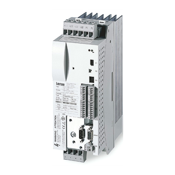
-
Contents
-
Table of Contents
-
Troubleshooting
-
Bookmarks
Quick Links
EDBCSXM064
.LKp
ECS
ECSEMxxx / ECSDMxxx / ECSCMxxx
Axis module ˘ «Motion»
Operating Instructions
l
Related Manuals for Lenze ECS Series
Summary of Contents for Lenze ECS Series
-
Page 1
EDBCSXM064 .LKp Operating Instructions ECSEMxxx / ECSDMxxx / ECSCMxxx Axis module ˘ «Motion»… -
Page 2
0Fig. 0Tab. 0 © 2013 Lenze Drive Systems GmbH, Hans−Lenze−Straße 1, 31855 Aerzen No part of this documentation may be reproduced or made accessible to third parties without written consent by Lenze Drive Sy- stems GmbH. All information given in this documentation has been selected carefully and complies with the hardware and software described. -
Page 3
ECSEA_003A EDBCSXM064 EN 11.0… -
Page 4
Scope of supply Position Description Quantity ECSLM… axis module Accessory kit with fixing material corresponding to the design (L): «E» − standard panel−mounted unit «D» − push−through technique «C» − cold−plate technique Mounting Instructions Drilling jig Functional earth conductor (only ECSDM…) Note! The ECSZA000X0B connector set must be ordered separately. -
Page 5: Table Of Contents
…………General safety and application notes for Lenze controllers .
-
Page 6
……. . . Entry of motor data for Lenze motors . -
Page 7
Contents Setting of the feedback system for position and speed control ….6.7.1 Resolver as position and speed encoder ……6.7.2 Resolver as absolute value encoder . -
Page 8
Contents 6.19 Operation with motors from other manufacturers ……6.19.1 Entering motor data manually ……..6.19.2 Checking the direction of rotation of the motor feedback system . -
Page 9
Contents Monitoring functions …………Fault responses . -
Page 10
Contents Troubleshooting and fault elimination ……..11.1 Fault analysis . -
Page 11: Preface And General Information
Preface and general information About these Operating Instructions Preface and general information About these Operating Instructions These Operating Instructions will assist you in connecting and commissioning the ECSxM… axis modules. They contain safety instructions which must be observed! All persons working on and with the ECSxM… axis modules must have the Operating Instructions available and must observe the information and notes relevant for their work.
-
Page 12: Terminology Used
(PLC) or further controllers exclusively via the X4 interface. Interface X14 (CAN−AUX) is exclusively used for parameter setting and diagnostics. Drive PLC Developer Studio (Lenze software for PLC programming acc. to IEC 61131) Global Drive Control (Lenze software for parameter setting and diagnostics)
-
Page 13: Code Descriptions
Preface and general information About these Operating Instructions Code descriptions 1.1.2 Code descriptions Lenze codes are described in the form of tables with the following structure: Column Abbreviation Meaning Cxxxx Code no. Cxxxx Subcode 1 of Cxxxx Subcode 2 of Cxxxx…
-
Page 14: Features Of The Axis Module Ecsxm (Motion)
Supported feedback systems: ƒ – Resolver with and without position storage – Encoder (incremental encoder (TTL encoder), sin/cos encoder) Commissioning, parameter setting and diagnostics with the Lenze parameter ƒ setting and operating program «Global Drive Control» (GDC) or the XT EMZ9371BC keypad…
-
Page 15: Structure
Structure UG+ UG- UG+ UG- PE PE ECSxM Digital_IO DI1: EtherCAT_SYNC AIF_IO Drive control C0135 C0576 C3160 C3161 C4010 = 2 C0579 C3002 C3152 Init C3162 (AIF) C3008 C3009 C3153 C3010 C3011 Stand by C3012 C3020 Control word Trouble ManJog CAN_IO C3021 C3022…
-
Page 16: Scope Of Supply
Components for operation and communication ƒ Brake resistors ƒ Mains fuses ƒ Mains chokes ƒ RFI filters ƒ Tip! Information and auxiliary devices related to the Lenze products can be found in the download area at http://www.Lenze.com EDBCSXM064 EN 11.0…
-
Page 17: Legal Regulations
Instructions. The specifications, processes, and circuitry described in these Instructions are for guidance only and must be adapted to your own specific application. Lenze does not take responsibility for the suitability of the process and circuit proposals.
-
Page 18: Safety Instructions
Lenze Automation GmbH does not accept any liability for the suitability of the procedures and circuit proposals described. Depending on their degree of protection, some parts of the Lenze controllers ƒ (frequency inverters, servo inverters, DC speed controllers) and their accessory components can be live, moving and rotating during operation.
-
Page 19
Safety instructions General safety and application notes for Lenze controllers Application as directed Controllers are components which are designed for installation in electrical systems or machines. They are not to be used as domestic appliances, but only for industrial purposes according to EN 61000−3−2. -
Page 20
Reduce housing openings and cutouts to a minimum. Lenze controllers may cause a DC current in the PE conductor. If a residual current device (RCD) is used for protection against direct or indirect contact for a controller with three−phase supply, only a residual current device (RCD) of type B is permissible on the… -
Page 21
Safety instructions General safety and application notes for Lenze controllers Safety functions Certain controller versions support safety functions (e.g. «Safe torque off», formerly «Safe standstill») according to the requirements of the EC Directive 2006/42/EC (Machinery Directive). The notes on the integrated safety system provided in this documentation must be observed. -
Page 22: Thermal Motor Monitoring
179 s in the event of a motor with a thermal motor time constant of 5 minutes (Lenze setting C0128), a motor current of 1.5 x I and a trigger threshold of 100 %.
-
Page 23: Forced Ventilated Or Naturally Ventilated Motors
C0120 (OC6) or C0127 (OC8). Read release time in the diagram Diagram for detecting the release times for a motor with a thermal motor time constant of 5 minutes (Lenze setting C0128): = 1 × I L [%] = 3 ×…
-
Page 24: Self−Ventilated Motors
C0129/x. Parameter setting The following codes can be set for I x t monitoring: Code Meaning Value range Lenze setting C0066 Display of the I x t load of the motor 0 … 250 % − C0120 Threshold: Triggering of error «OC6″…
-
Page 25
Safety instructions Thermal motor monitoring Self−ventilated motors Calculate release time and I x t load Calculate the release time and the I x t load of the motor considering the values in C0129/1 and C0129/2(evaluation coefficient «y»). Formulae for release time Information Release time of the I x t monitoring… -
Page 26: Residual Hazards
ECSxE supply module and the input current ƒ limitation is activated depending on the DC−bus voltage (C0175 = 1 or 2). the axis module is not supplied via a supply module delivered by Lenze. ƒ the low−voltage supply (24 V) is switched off.
-
Page 27
Motor protection Only use motors with a minimum insulation resistance of û = 1.5 kV, ƒ min. du/dt = 5 kV/ms. – Lenze motors meet these requirements. When using motors with an unknown insulation resistance, please contact your ƒ motor supplier. -
Page 28: Safety Instructions For The Installation According To Ul
Safety instructions Safety instructions for the installation according to UL Safety instructions for the installation according to UL Warnings! General markings: Use 60/75 °C or 75 °C copper wire only. ƒ Maximum ambient temperature 55 °C, with reduced output current. ƒ…
-
Page 29: Notes Used
Safety instructions Notes used Notes used The following pictographs and signal words are used in this documentation to indicate dangers and important information: Safety instructions Structure of safety instructions: Danger! (characterises the type and severity of danger) Note (describes the danger and gives information about how to prevent dangerous situations) Pictograph and signal word Meaning…
-
Page 30: Technical Data
Technical data General data and operating conditions Technical data General data and operating conditions Standards and operating conditions Conformity Low−Voltage Directive (2006/95/EG) Approvals UL 508C Power Conversion Equipment Underwriter Laboratories (File No. E132659) CSA 22.2 No. 14 for USA and Canada Max.
-
Page 31
Technical data General data and operating conditions General electrical data Compliance with the requirements acc. to EN 61800−3 Noise emission Compliance with the limit class C2 acc. to EN 61800−3 (achieved by using collective filters typical for the application) Noise immunity Requirements acc. -
Page 32: Rated Data
Technical data Rated data Rated data Axis module Rated data Type ECSxL004 ECSxL008 ECSxL016 Output power 400 V mains [kVA] rated Data for operation with upstream power supply module mains on mains voltage DC−bus voltage 15 … 770 DC−bus DC−bus current DC−bus Rated output current at 4 kHz (causes a heatsink temperature of 70°C at an ambient…
-
Page 33
Technical data Rated data Rated data Type Axis module ECSxL032 ECSxL048 ECSxL064 Output power 400 V mains [kVA] 11.2 13.2 rated Data for operation with upstream power supply module mains on mains voltage DC−bus voltage 15 … 770 DC−bus DC−bus current 15.6 12.5 20.9… -
Page 34: Current Characteristics
Technical data Current characteristics Increased continuous current depending on the control factor Current characteristics 3.3.1 Increased continuous current depending on the control factor In the lower speed range ˘ the motor does not need the full motor voltage ˘ particularly the more powerful ECS axis modules can be permanently operated with increased output ^ 32).
-
Page 35
Technical data Current characteristics Increased continuous current depending on the control factor The following table shows the connections between mains voltage, DC−bus voltage and motor voltage: Mains voltage DC−bus voltage Output voltage (motor voltage) nominally achievable for 100 % x 1.35] mains mains modulation… -
Page 36
Technical data Current characteristics Increased continuous current depending on the control factor Example: The ECS axis module suitable for operation in conjunction with a Lenze motor of type MCS 14L32 is to be determined. Rated motor data ƒ – Rated motor torque (M ) = 17.2 Nm… -
Page 37: Device Protection By Current Derating
Technical data Current characteristics Device protection by current derating 3.3.2 Device protection by current derating The maximum output current is limited. With output frequencies < 5 Hz the limitation depends on the heatsink temperature. ‚ 1.00 1.00 Iout ≤ 70 °C Imax …
-
Page 38: Mechanical Installation
– Ensure unimpeded ventilation of cooling air and outlet of exhaust air. – Several modules of the ECS series can be installed in the control cabinet next to each other without any clearance. The mounting plate of the control cabinet ƒ…
-
Page 39: Mounting With Fixing Rails (Standard Installation)
Mechanical installation Mounting with fixing rails (standard installation) Dimensions Mounting with fixing rails (standard installation) 4.2.1 Dimensions Note! Mounting with ECSZS000X0B shield mounting kit: Mounting clearance below the module > 195 mm ƒ ECSxA005 Fig. 4−1 Dimensions for «panel−mounted» design Axis module Dimensions [mm] Type…
-
Page 40: Mounting Steps
Mechanical installation Mounting with fixing rails (standard installation) Mounting steps 4.2.2 Mounting steps How to install the axis module: 1. Prepare the fixing holes on the mounting surface. – Use the drilling jig for this purpose. 2. Take the fixing rails from the accessory kit in the cardboard box. 3.
-
Page 41: Mounting With Thermal Separation (Push−Through Technique)
Mechanical installation Mounting with thermal separation (push−through technique) Mounting with thermal separation (push−through technique) For the push−through technique the rear panel of the control cabinet must be a steel plate with a thickness of at least 2 mm. The edges of the mounting cutout and the fixing holes for the clamps must be slightly curved inwards (towards the axis module).
-
Page 42: Dimensions
Mechanical installation Mounting with thermal separation (push−through technique) Dimensions 4.3.1 Dimensions Note! Mounting with ECSZS000X0B shield mounting kit: Mounting clearance below the module > 195 mm ƒ ECSXA007 Fig. 4−2 Dimensions for «push−through design» Mounting cutout (a1 x b1), ^ 43 Axis module Dimensions [mm] Type…
-
Page 43
Mechanical installation Mounting with thermal separation (push−through technique) Dimensions Dimensions of mounting cutout Note! Installation with shield mounting ECSZS000X0B: Clearance below the mounting cutout > 220 mm ƒ ECSXA063 Fig. 4−3 Dimensions of mounting cutout Mounting surface Mounting cutout for size 0 Mounting cutout for size 1 Axis module Dimensions [mm]… -
Page 44: Mounting Steps
Mechanical installation Mounting with thermal separation (push−through technique) Mounting steps 4.3.2 Mounting steps How to mount the axis module: 1. Prepare the fixing holes for the wire clamps on the mounting area. For this purpose, apply a drilling jig. 2. Prepare the mounting cutout. The edges of the mounting cutout and the fixing holes for the wire clamps have to be slightly arched inwardly (to the axis module).
-
Page 45: Mounting In Cold−Plate Design
Mechanical installation Mounting in cold−plate design Mounting in cold−plate design The axis modules ECSC… are intended for mounting in cold−plate design (e.g. on collective coolers). Requirements for collective coolers The following requirements must be met to ensure a safe operation of the axis modules: Good thermal contact with the cooler ƒ…
-
Page 46: Dimensions
Mechanical installation Mounting in cold−plate design Dimensions 4.4.1 Dimensions Note! Mounting with ECSZS000X0B shield mounting kit: Mounting clearance below the module > 195 mm ƒ ECSXA009 Fig. 4−5 Dimensions for «cold−plate design» Axis module Dimensions [mm] Type Size ECSC ECSC 88,5 ECSC ECSC…
-
Page 47: Mounting Steps
Mechanical installation Mounting in cold−plate design Mounting steps 4.4.2 Mounting steps À Á Â ECSXA030 Fig. 4−6 Mounting for «cold−plate design» Proceed as follows to mount the axis module: 1. Prepare the fixing holes on the mounting plate. – Use a drilling jig for this purpose. 2.
-
Page 48: Electrical Installation
Electrical installation Installation according to EMC (installation of a CE−typical drive system) Electrical installation Installation according to EMC (installation of a CE−typical drive system) General information The electromagnetic compatibility of a machine depends on the type of installation ƒ and care taken.Especially consider the following: –…
-
Page 49
Electrical installation Installation according to EMC (installation of a CE−typical drive system) Assembly Connect the ECS modules, RFI filters, and mains choke to the earthed mounting ƒ plate with a surface as large as possible: – Mounting plates with conductive surfaces (zinc−coated or stainless steel) allow for permanent contact. -
Page 50
Electrical installation Installation according to EMC (installation of a CE−typical drive system) Shielding Connect the motor cable shield to the axis module ƒ – with the ECSZS000X0B shield mounting kit. – extensively to the mounting plate below the axis module. –… -
Page 51: Power Terminals
Electrical installation Power terminals Power terminals ECSXA080 Fig. 5−1 Plug connectors for power terminals Danger! Dangerous voltage The leakage current to earth (PE) is > 3.5 mA AC or > 10 mA DC. Possible consequences: Death or severe injuries when the device is touched in the event of a fault. ƒ…
-
Page 52
Electrical installation Power terminals All power connections are plug connections and coded. The ECSZA000X0B plug ƒ connector set must be ordered separately. Installation of the cables to EN 60204−1. ƒ The cables used must comply with the approvals required at the site of use (e.g. VDE, ƒ… -
Page 53
Electrical installation Power terminals Shielded cables The following factors decisively determine the effect of the shielded cables: Good shield connection ƒ – Ensure a contact surface as large as possible Low shield resistance ƒ – Only use shields with tin−plated or nickel−plated copper braids (shields with steel braids cannot be used). -
Page 54: Connection To The Dc Bus (+Ug, −Ug)
Electrical installation Power terminals Connection to the DC bus (+U , −U 5.2.1 Connection to the DC bus (+U , −U Stop! No device protection for DC bus voltage surges In passive axis modules (without 24 V−supply), the charging circuit can be overloaded through DC bus voltage surges.
-
Page 55
Power terminals Connection to the DC bus (+U , −U Fuses Mains fuses are not included in the Lenze delivery program. Use standard fuses. ƒ When using ECSxE power supply modules which are fused on the supply side the ƒ… -
Page 56: Connection Plan For Mimimum Wiring With Internal Brake Resistor
Electrical installation Power terminals Connection plan for mimimum wiring with internal brake resistor 5.2.2 Connection plan for mimimum wiring with internal brake resistor Documentation of the ECSxE power supply module Observe the enclosed notes. Stop! Always operate the ECS power supply modules with a brake resistor (internal/external).
-
Page 57
Electrical installation Power terminals Connection plan for mimimum wiring with internal brake resistor F1…F3 » » L3 PE +UG +UG +UG +UG ECSEE… ECSxS/P/M/A… ECSxS/P/M/A… ECSDE… BD1 BD2 U V W PE BD1 BD2 U V W PE » » «… -
Page 58: Connection Plan For Mimimum Wiring With External Brake Resistor
Electrical installation Power terminals Connection plan for mimimum wiring with external brake resistor 5.2.3 Connection plan for mimimum wiring with external brake resistor Documentation of the ECSxE power supply module Observe the enclosed notes. Stop! Always operate the ECS power supply modules with a brake resistor. ƒ…
-
Page 59
Electrical installation Power terminals Connection plan for mimimum wiring with external brake resistor F1…F3 » » L3 PE +UG +UG +UG +UG ECSxE… ECSxS/P/M/A… ECSxS/P/M/A… BD1 BD2 U V W PE BD1 BD2 U V W PE » » » «… -
Page 60: Motor Connection
) when using synchronous motors or according to the rated motor current ) for asynchronous motors. Length of the unshielded ends: 40 … 100 mm (depending on the cable cross−section) ƒ Lenze system cables meet these requirements. ƒ Use the ECSZS000X0B shield mounting kit for EMC−compliant wiring. ƒ…
-
Page 61: Motor Holding Brake Connection
Electrical installation Power terminals Motor holding brake connection 5.2.5 Motor holding brake connection The motor holding brake is connected to X25/BD1 and X25/BD2. ƒ is supplied with low voltage via the terminals X6/B+ and X6/B−: ƒ +23 … +30 V DC, max.1.5 A Stop! Protect X6/B+ with an F 1.6 A fuse.
-
Page 62
1.5 V is produced. The voltage drop can be compensated by a higher voltage at the cable entry. The voltage required at X6/B+ and X6/B− for the Lenze system cables is calculated as follows: [V] + U [V] ) 0.08… -
Page 63: Connection Of An Ecsxk
Electrical installation Power terminals Connection of an ECSxK… capacitor module (optional) 5.2.6 Connection of an ECSxK… capacitor module (optional) The ECS capacitor modules support the DC−bus voltage for the drive system. These capacitor module types are available: ECSxK001 (705 mF, ±20 %) ƒ…
-
Page 64: Control Terminals
Electrical installation Control terminals Control terminals ECSXA070 Fig. 5−7 Plug connectors for control terminals (X6) For the supply of the control electronics an external 24 V DC voltage at terminals X6/+24 and X6/GND is required. Stop! The control cables must always be shielded to prevent interference ƒ…
-
Page 65
Electrical installation Control terminals Shield connection of control cables and signal cables The plate on the front of the device serves as the mounting place (two threaded holes M4) for the shield connection of the signal cables. The screws used may extend into the inside of the device by up to 10 mm. -
Page 66
(central controller enable) of the power supply module via the relay 0. – In the default Lenze setting of the ECS axis modules, DO1 is set to «ready». «Ready» is only present if a specified DC−bus voltage has been reached. -
Page 67
Electrical installation Control terminals Assignment of the plug connectors Plug connector X6 Terminal Function Electrical data X6/+24 Low−voltage supply of the control electronics 20 … 30 V DC, 0. A (max. 1 A) for starting current of 24 V: X6/GND Reference potential of low−voltage supply max. -
Page 68: Digital Inputs And Outputs
Electrical installation Control terminals Digital inputs and outputs 5.3.1 Digital inputs and outputs Stop! If an inductive load is connected to X6/DO1, a spark suppressor with a limiting function to max. 50 V ± 0 % must be provided. GNDext DI1 DI2 DI3 DI4 «…
-
Page 69: Analog Input
Electrical installation Control terminals Analog input 5.3.2 Analog input » » ECSXA015 Fig. 5−10 Analog input at X6 » HF−shield termination by large−surface connection to functional earth (see Mounting Instructions for ECSZS000X0B shield mounting kit) Analog input configuration Use C0034 to set whether the input is to be used for a master voltage (±10 V) or a ƒ…
-
Page 70: Safe Torque Off
Electrical installation Control terminals Safe torque off 5.3.3 Safe torque off The axis modules support the «safe torque off» safety function (formerly «safe standstill»), «protection against unexpected start−up», in accordance with the requirements of EN ISO 13849−1, Performance Level Pld. For this purpose, the axis modules are equipped with two independent safety paths.
-
Page 71
Electrical installation Control terminals Safe torque off 5.3.3.2 Functional description The «safe torque off» state can be initiated any time via the input terminals X6/SI1 (controller enable/inhibit) and X6/SI2 (pulse enable/inhibit). For this purpose a LOW level has to be applied at both terminals: X6/SI1 = LOW (controller inhibited): ƒ… -
Page 72
Electrical installation Control terminals Safe torque off 5.3.3.3 Important notes Danger! When using the «safe torque off» function, additional measures are required for «emergency stops»! There is neither an electrical isolation between motor and axis module nor a «service» or «repair switch». Possible consequences: Death or severe injuries ƒ… -
Page 73
Electrical installation Control terminals Safe torque off 5.3.3.4 Technical data Terminal assignment Plug connector X6 Terminal Function Level Electrical data X6/S24 Low−voltage supply 18 … 30 V DC 0.7 A X6/SO «Safe torque off» feedback During operation 24 V DC output 0.7 A (max. -
Page 74
Electrical installation Control terminals Safe torque off 5.3.3.5 Function check After installation the operator must check the «safe torque off» function. ƒ The function check must be repeated at regular intervals, after one year at the ƒ latest. Stop! If the function check leads to impermissible states at the terminals, commissioning cannot take place! Test specifications Check the circuitry with regard to correct function. -
Page 75
Electrical installation Control terminals Safe torque off 5.3.3.6 Example: Wiring with electronic safety switching device «Pilz PNOZ e1vp» for Performance Level Pl 24V DC Start ECSxS/P/M/A Not-Halt/ Emergency stop Pilz PNOZ e1vp 10s 24V DC Pilz 774195 Pilz 774195 ECSXA034 Fig. -
Page 76
PL in accordance with EN ISO 13849−1 or SIL 2 in accordance with EN 62061 are to be used in all upstream applications! Interconnection examples can be found in the download area (Application Knowledge Base) at: www.Lenze.com EDBCSXM064 EN 11.0… -
Page 77
Electrical installation Control terminals Safe torque off 5.3.3.7 Example: Wiring with electromechanical safety switching device «Siemens 3TK2827» for Performance Level Pl Not-Halt/ Emergency stop 24V DC Siemens 3TK2827 ECSxS/P/M/A Start ECSXA035 Fig. 5−13 Example: Wiring with «Siemens 3TK2827» safety switching device T1 Test key 1 T2 Test key 2 The motor is shut down in accordance with stop category 1 of EN 60204 when the… -
Page 78
PL in accordance with EN ISO 13849−1 or SIL 2 in accordance with EN 62061 are to be used in all upstream applications! Interconnection examples can be found in the download area (Application Knowledge Base) at: www.Lenze.com EDBCSXM064 EN 11.0… -
Page 79: Automation Interface (Aif)
Electrical installation Automation interface (AIF) Automation interface (AIF) The keypad XT or a communication module can be attached to or removed from the automation interface (X1). This is also possible during operation. The keypad XT serves to enter and visualise parameters and codes. ƒ…
-
Page 80: Wiring Of System Bus (Can)
MotionBus (CAN) with master control ECS_COB007 Fig. 5−15 MotionBus (CAN) with controller as master MotionBus (CAN), interface X4 System bus (CAN), interface X14 Master Slave PC with the Lenze parameter setting and operating software (GDC, GDL, GDO) HMI / operating unit EDBCSXM064 EN 11.0…
-
Page 81
Electrical installation Wiring of system bus (CAN) ECS_COB003 Fig. 5−16 Bus connections on the controller Assignment of the plug connectors X4 (CAN) X14 (CAN−AUX) Description CAN−HIGH CAN−LOW Reference potential Specification of the transmission cable We recommend the use of CAN cables in accordance with ISO 11898−2: CAN cable in accordance with ISO 11898−2 Cable type Paired with shielding… -
Page 82
Electrical installation Wiring of system bus (CAN) System bus (CAN) wiring ECS_COB004 Fig. 5−17 Example: System bus (CAN) wiring via interface X4 ECS axis module Master control, e.g. ETC Note! Connect one bus terminating resistor (120 W) each to the first and last node of the system bus (CAN). -
Page 83
Electrical installation Wiring of system bus (CAN) Bus cable length Note! The permissible cable lengths must be observed. 1. Check the compliance with the total cable length in Tab. 5−1. The baud rate determines the total cable length. CAN baud rate [kbit/s] Max. -
Page 84
It is not possible to use a cable length of 450 m without using a repeater. After 360 m (point 2) a repeater must be installed. Result The Lenze repeater type 2176 is used (cable reduction: 30 m) Calculation of the maximum cable length: First segment: 360 m Second segment: 360 m (according to Tab. -
Page 85: Wiring Of The Feedback System
(e.g. by using separating webs or separated trailing cables) is not ensured on the entire cable length cable due to an installation on the system side, the encoder cable must be provided with an insulation resistance of 300 V. Lenze encoder cables meet this requirement.
-
Page 86: Resolver Connection
Wiring of the feedback system Resolver connection 5.6.1 Resolver connection Note! Use the prefabricated Lenze system cables for the connection of a resolver. ƒ Cable length: max. 50 m ƒ Depending on the cable length and resolver used parameterise the code ƒ…
-
Page 87: Encoder Connection
Electrical installation Wiring of the feedback system Encoder connection 5.6.2 Encoder connection Danger! Valid when using an operating software up to and including V7.0: When absolute value encoders are used, uncontrolled movements of the drive are possible! If an absolute value encoder is disconnected from the axis module during operation, the fault OH3−TRIP occurs.
-
Page 88
Electrical installation Wiring of the feedback system Encoder connection Incremental encoder (TTL encoder) Features Input/output frequency: 0 … 200 kHz Current consumption: 6 mA per channel Current on output V (X8/pin 4): Max. 200 mA < 50 m R1 (+KTY) R2 (-KTY) ECSXA026 Fig. -
Page 89
Electrical installation Wiring of the feedback system Encoder connection SinCos encoders and SinCos absolute value encoders with Hiperface Features Input/output frequency: 0 … 200 kHz 221 W Internal resistance (R Offset voltage for signals SIN, COS, Z: 2.5 V The differential voltage between signal track and reference track must not exceed ƒ… -
Page 90: Digital Frequency Input/Output (Encoder Simulation)
Electrical installation Wiring of the feedback system Digital frequency input/output (encoder simulation) 5.6.3 Digital frequency input/output (encoder simulation) The digital frequency coupling of ECSxS/P/A axis modules basically is effected as a master−slave connection via the interface X8. This interface can either be used as a digital frequency input or as a digital frequency output (e.
-
Page 91
Electrical installation Wiring of the feedback system Digital frequency input/output (encoder simulation) 2 to 3 slaves connected to the master: ƒ Use the EMF2132IB digital frequency distributor to wire the ECS axis modules with master digital frequency cable EYD0017AxxxxW01W01 and slave digital frequency cable EYD0017AxxxxW01S01. -
Page 92: Commissioning
Before you start Commissioning Before you start Note! The use of a Lenze motor is assumed in this description of the ƒ commissioning steps. For details on the operation with other motors see ^ 174. The operation with the Lenze parameter setting and operating program ƒ…
-
Page 93: Commissioning Steps (Overview)
Commissioning Commissioning steps (overview) Commissioning steps (overview) Start Carry out the basic setting (^ 94) Set homing (^ 96) Optimise drive behaviour (^ 183) Save parameters in the drive with C0003 = 1. Save parameter set with GDC in the parameter set file. EDBCSXM064 EN 11.0…
-
Page 94: Basic Settings With Gdc
ð The drive is identified and the parameter menu is opened. ^ 100 Load Lenze setting. Not required for initial commissioning of the axis module. Only recommended if the Lenze setting is unclear. Set communication Comm. parameters − AIF interface: parameters according the Please also read the documentation for the Lenze interface used.
-
Page 95
Detailed information ^ 109 Set feedback system. Set Lenze motors with resolvers (standard) in the GDC parameter menu under Short setup W Feedback system. Set other resolvers and encoders in the GDC parameter menu under Motor/feedback systems W Feedback system. -
Page 96: Setting Of Homing
Commissioning Commissioning steps (overview) Setting of homing 6.2.2 Setting of homing Homing By means of homing, the zero position is defined within the physically possible traversing range of the machine. Thus, the reference of the measuring systems to the machine is established.
-
Page 97
Commissioning Commissioning steps (overview) Setting of homing The homing setting described in this chapter requires the following system structure: CAN-AUX ECSxM… DI1 DI2 DI3 DI4 ECSXA500 Fig. 6−2 Basic system structure ECSxM… axis module with «Motion» application software Speed / position feedback Motor power connection Change−over between reference switch and touch probe sensor (only required in the homing modes 6 and 7! ^ 145) -
Page 98
Commissioning Commissioning steps (overview) Setting of homing Setting sequence: Comply with … the safety and application instructions for multi−axis applications in the corresponding manuals and on the systems. Note! Follow the commissioning steps in the given order! Settings Brief description Detailed information Activate controller inhibit. -
Page 99
Commissioning Commissioning steps (overview) Setting of homing Settings Brief description Detailed information ^ 161 A Select «Interpolated The «Interpolated Position Mode» is automatically selected Position Mode». by the higher−level control (PLC): C5000 = 7 The operating mode can also be set manually in the GDC parameter menu under Motion W Operating mode. -
Page 100: Loading The Lenze Setting
Loading the Lenze setting Loading the Lenze setting Note! When loading the Lenze setting, all parameters are reset to the basic setting defined by Lenze. Settings that have been adjusted before get lost during this process! In GDC, you can find the parameters and codes to be set in the parameter menu under Load / Save / PLC.
-
Page 101: Setting Of Mains Data
Therefore, set C0175 = 3 for the axis modules (charging current limitation inactive, charging resistor short−circuited). If the Lenze setting has been loaded via C0002, C0175 = 3 must be reset. Cyclic switching of the mains voltage at the power supply module can ƒ…
-
Page 102: Setting The Voltage Thresholds
[V AC] [V DC] [V DC] yes/no yes/no 400 … 460 yes/no yes/no C0174 C0174 + 5 V 400 (Lenze setting) yes/no C0174 C0174 + 5 V 400 … 460 yes/no C0174 C0174 + 5 V C0174 C0174 + 5 V…
-
Page 103: Entry Of Motor Data For Lenze Motors
The following only describes the parameter setting for Lenze motors! (If you ƒ use a motor from another manufacturer, see ^ 174.) If the Lenze setting has been loaded via C0002, the motor data must be ƒ re−entered. The freely available «GDC−Easy» does not provide the «Input assistant for ƒ…
-
Page 104
Commissioning Entry of motor data for Lenze motors ECSXA302 Fig. 6−6 GDC view: Motor selection 3. Select the connected motor from the list (see motor nameplate). – The corresponding motor data is displayed in the «Motor data» fields on the right. -
Page 105: Holding Brake Configuration
Note! The codes C0195, C0196, C0244, C0472/10 and C0472/11 are only effective if the brake logic is active (C4020 = 1). Code Possible settings IMPORTANT Designation Lenze/ Selection {Appl.} ^ 105 C4020 Brake logic Activate brake logic Brake Off Brake On…
-
Page 106
C0472/11 FCODE analog [%] Value/direction of the torque against the holding brake. C0118 Polarity of the digital In the Lenze setting, the outputs are «HIGH level active» (^ 142). outputs C0118/1: Output X6/DO1 (DIGOUT_bOut1_b) C0118/2: Output X25 (DIGOUT_bRelais_b, brake connection) C0602 Fault response −… -
Page 107: Closing The Brake
Commissioning Holding brake configuration Closing the brake 6.6.1 Closing the brake Use control bit 7 = 0 (FALSE) to close the brake. CtrlWord.Bit7 At the same time the internal quick stop (QSP) is activated and the drive is braked to standstill within the deceleration time set in C0105 (NSet = 0).
-
Page 108: Opening The Brake
Commissioning Holding brake configuration Opening the brake 6.6.2 Opening the brake Use control bit 7 = 1 (TRUE) to enable the CtrlWord.Bit7 controller. The control bit 9 is set to 0 (FALSE) at the same time (controller inhibit (CINH) is deactivated) and the torque defined in C0244 is created.
-
Page 109: Setting Of The Feedback System For Position And Speed Control
The GDC includes the parameters or codes to be set in the parameter menu under Short setup W Feedback system: ECSXA532 Fig. 6−8 GDC view: Commissioning of the feedback system Note! If the Lenze setting has been loaded via C0002, the feedback system must be reset. EDBCSXM064 EN 11.0…
-
Page 110: Resolver As Position And Speed Encoder
Resolver as position and speed encoder If a resolver is connected to X7 and used as a position and speed encoder, no settings are necessary. Lenze setting: Resolver as position encoder: C0490 = 0 ƒ Resolver as speed encoder: C0495 = 0 ƒ…
-
Page 111
Selection {Appl.} ^ 180 C0058 Rotor diff −90.0 Rotor displacement angle (offset angle) Input in case of Lenze motor with resolver: −90° hiperface absolute value encoder: 0° Code value is adapted by the rotor position adjustment function (C0095). Only relevant for the operation of synchronous motors. -
Page 112: Resolver As Absolute Value Encoder
(number of pole pairs > 1): 180° Max. rotation + » number_of_pole_pairs Code Possible settings IMPORTANT Designation Lenze/ Selection {Appl.} ^ 112 C3002 NoChangeOf Resolver as absolute value encoder ChangeOfPos After «mains off/on», homing has to be carried out.
-
Page 113: Ttl/Sincos Encoder As Position And Speed Encoder
Commissioning Setting of the feedback system for position and speed control TTL/SinCos encoder as position and speed encoder 6.7.3 TTL/SinCos encoder as position and speed encoder If an incremental encoder or a SinCos encoder without serial communication is connected to X8 and used for position and speed control, comply with the following setting sequence: 1.
-
Page 114
Selection {Appl.} ^ 180 C0058 Rotor diff −90.0 Rotor displacement angle (offset angle) Input in case of Lenze motor with resolver: −90° hiperface absolute value encoder: 0° Code value is adapted by the rotor position adjustment function (C0095). Only relevant for the operation of synchronous motors. -
Page 115
Active ^ 113 [C0419] Enc. setup Encoder selection ^ 121 Selection of encoder type indicated on the nameplate of the Lenze motor. The encoder data (C0420, C0421, C0427) is set automatically in accordance with the selection. Common IT512−5V Incremental encoder with TTL level IT1024−5V… -
Page 116
Commissioning Setting of the feedback system for position and speed control TTL/SinCos encoder as position and speed encoder Code Possible settings IMPORTANT Designation Lenze/ Selection {Appl.} ^ 113 [C0427] Enc. signal Function of the master frequency ^ 121 input signals on X8 (DFIN) 2−phase… -
Page 117: Ttl/Sincos Encoder As Position Encoder And Resolver As Speed Encoder
Commissioning Setting of the feedback system for position and speed control TTL/SinCos encoder as position encoder and resolver as speed encoder 6.7.4 TTL/SinCos encoder as position encoder and resolver as speed encoder A TTL incremental encoder connected to X8 or a SinCos encoder without serial communication can be configured as a position encoder with a resolver connected to X7 being used as a speed encoder.
-
Page 118
Selection {Appl.} ^ 180 C0058 Rotor diff −90.0 Rotor displacement angle (offset angle) Input in case of Lenze motor with resolver: −90° hiperface absolute value encoder: 0° Code value is adapted by the rotor position adjustment function (C0095). Only relevant for the operation of synchronous motors. -
Page 119
Setting of the feedback system for position and speed control TTL/SinCos encoder as position encoder and resolver as speed encoder Code Possible settings IMPORTANT Designation Lenze/ Selection {Appl.} ^ 180 [C0095] Rotor pos adj Activation of rotor position adjustment for automatic determination of the rotor displacement angle. -
Page 120
{Appl.} ^ 113 [C0419] Enc. setup Encoder selection ^ 121 Selection of encoder type indicated on the nameplate of the Lenze motor. The encoder data (C0420, C0421, C0427) is set automatically in accordance with the selection. Common IT512−5V Incremental encoder with TTL level IT1024−5V… -
Page 121: Absolute Value Encoder As Position And Speed Encoder
Commissioning Setting of the feedback system for position and speed control Absolute value encoder as position and speed encoder 6.7.5 Absolute value encoder as position and speed encoder Danger! Valid when using an operating software up to and including V7.0: When absolute value encoders are used, uncontrolled movements of the drive are possible! If an absolute value encoder is disconnected from the axis module during…
-
Page 122
Commissioning Setting of the feedback system for position and speed control Absolute value encoder as position and speed encoder Danger! When absolute value encoders are used, uncontrolled movements of the drive are possible! With operating systems up to and including version 6.7, the drive may start up in an uncontrolled manner with high speed and high torque after mains connection and controller enable. -
Page 123
Selection {Appl.} ^ 180 C0058 Rotor diff −90.0 Rotor displacement angle (offset angle) Input in case of Lenze motor with resolver: −90° hiperface absolute value encoder: 0° Code value is adapted by the rotor position adjustment function (C0095). Only relevant for the operation of synchronous motors. -
Page 124
Active ^ 113 [C0419] Enc. setup Encoder selection ^ 121 Selection of encoder type indicated on the nameplate of the Lenze motor. The encoder data (C0420, C0421, C0427) is set automatically in accordance with the selection. Common IT512−5V Incremental encoder with TTL level IT1024−5V… -
Page 125
Commissioning Setting of the feedback system for position and speed control Absolute value encoder as position and speed encoder Code Possible settings IMPORTANT Designation Lenze/ Selection {Appl.} ^ 113 [C0427] Enc. signal Function of the master frequency ^ 121 input signals on X8 (DFIN) 2−phase… -
Page 126: Absolute Value Encoder As Position Encoder And Resolver As Speed Encoder
Commissioning Setting of the feedback system for position and speed control Absolute value encoder as position encoder and resolver as speed encoder 6.7.6 Absolute value encoder as position encoder and resolver as speed encoder Danger! Valid when using an operating software up to and including V7.0: When absolute value encoders are used, uncontrolled movements of the drive are possible! If an absolute value encoder is disconnected from the axis module during…
-
Page 127
Do not parameterise codes C0420, C0421 and C0427! ƒ 4. Save settings with C0003 = 1. Codes for feedback system selection Code Possible settings IMPORTANT Designation Lenze/ Selection {Appl.} ^ 109 [C0490] Feedback pos Selection of feedback system for positioning control Resolver at X7… -
Page 128
Selection {Appl.} ^ 180 C0058 Rotor diff −90.0 Rotor displacement angle (offset angle) Input in case of Lenze motor with resolver: −90° hiperface absolute value encoder: 0° Code value is adapted by the rotor position adjustment function (C0095). Only relevant for the operation of synchronous motors. -
Page 129
{Appl.} ^ 113 [C0419] Enc. setup Encoder selection ^ 121 Selection of encoder type indicated on the nameplate of the Lenze motor. The encoder data (C0420, C0421, C0427) is set automatically in accordance with the selection. Common IT512−5V Incremental encoder with TTL level IT1024−5V… -
Page 130: Selecting The Control Interface (C4010)
The control interface is used to transmit process data cyclically between the higher−level control and the axis module. The following fieldbus interfaces can be selected under C4010: Code Possible settings IMPORTANT Designation Lenze/ Selection {Appl.} ^ 130 C4010 Ctrl_Interf Control interface selection ^ 167…
-
Page 131: Process Data To The Axis Module (Control Word Ctrl1 And Setpoints)
– if required, to transmit the monitor data for diagnostic purposes. The system bus interface X14 can only be used for parameter setting and ƒ diagnostics with the Lenze parameter setting and operating program «Global Drive Control» (GDC). Further information on communication can be found in chapter ƒ…
-
Page 132
Commissioning Process data to the axis module (control word Ctrl1 and setpoints) Control word Ctrl1 The control word Ctrl1 consists of 16 bits which are displayed bit by bit under C3151/x: Bit Designation Level Meaning Toggle HIGH active Toggle bit: The master control changes the status of this bit with each telegram. -
Page 133
Commissioning Process data to the axis module (control word Ctrl1 and setpoints) Monitor data selection (C3181) Depending on the values of the control bits 4 … 6, the following monitor data can be transmitted from the drive: Ctrl1. Value of the Monitor data Meaning control… -
Page 134: Process Data From The Axis Module (Status Words And Actual Values)
Commissioning Process data from the axis module (status words and actual values) 6.10 Process data from the axis module (status words and actual values) The control interface set under C4010 (^ 130) is used to cyclically transmit process data from the axis module to the higher−level control. Structure of the transmitted process data User data Byte 1…
-
Page 135
Commissioning Process data from the axis module (status words and actual values) Status word Stat1 The status word Stat1 (C3150, C3151) consists of 16 bits, each of them giving the following information: Name Level Meaning Operating mode «Homing mode» Operating mode «IP mode» (C5000=6) (C5000=7) (^ 164) -
Page 136: Toggle−Bit Monitoring
Commissioning Process data from the axis module (status words and actual values) Toggle−bit monitoring 6.10.1 Toggle−bit monitoring Higher-level motion control Toggle bit Controller generator enable Drive Toggle-Bit Interrupted if Interrupted if Interrupted if controller is controller is controller is not enabled not enabled not enabled Toggle bit…
-
Page 137
In the GDC, the error limit (C3161) and error response (C3160) can be set in the parameter menu under Motion W Toggle bit monitoring. ECSXA545 Fig. 6−13 GDC view: Monitoring Code Possible settings IMPORTANT Designation Lenze/ Selection {Appl.} ^ 136 C3160 ToggleErrReac Toggle bit error handling TRIP Message Warning FAIL−QSP… -
Page 138: Entry Of Machine Parameters
Motion W Machine parameter. ECSXA535 Fig. 6−14 GDC view: Short setup, entry of machine parameters Code Possible settings IMPORTANT Designation Lenze/ Selection {Appl.} C0011 Nmax 3000 Maximum speed {1 rpm} 16000 Reference value for the absolute…
-
Page 139
Commissioning Entry of machine parameters Code Possible settings IMPORTANT Designation Lenze/ Selection {Appl.} ^ 170 C3032 FollErr1reac First reaction when following error limit has been reached TRIP Message Warning FAIL−QSP ^ 170 C3033 FollErr2reac Second reaction when following error limit has been reached… -
Page 140: Configuring The Digital Inputs And Outputs
The signal assignment for the digital inputs can be set via code C4011. This code is included in the GDC parameter menu under Short setup W Digital inputs/outputs. Code Possible settings IMPORTANT Designation Lenze/ Selection {Appl.} ^ 140 C4011 Assignment (mapping) of the digital inputs (from Motion V3.0)
-
Page 141: Digital Inputs For Communication Via The Motionbus (Can) X4
Commissioning Configuring the digital inputs and outputs Digital inputs for communication via the MotionBus (CAN) X4 6.12.1 Digital inputs for communication via the MotionBus (CAN) X4 Setting C4011 = 0: Terminal Function Level Response X6/DI1 Quick stop (QSP) The drive is decelerated to standstill within the deceleration time set in C0105.
-
Page 142: Setting The Polarity Of Digital Inputs And Outputs
The GDC contains codes for setting the polarity of digital inputs and outputs in the parameter menu under Terminal I/O: Code Possible settings IMPORTANT Designation Lenze/ Selection {Appl.} ^ 142 C0114 Polarity of the digital inputs (DIGIN)
-
Page 143: Setting Of Homing Parameters
ECSXA537 Fig. 6−15 GDC view: Short setup, entry of homing parameters 6.13.1 Homing parameters Code Possible settings IMPORTANT Designation Lenze/ Selection {Appl.} ^ 143 C0935 L_REF1 speed Traversing speed of homing {1 rpm} 16000 ) of homing ^ 143 C0936 L_REF1 Ti Deceleration time (T 0.01…
-
Page 144
Commissioning Setting of homing parameters Homing parameters Code Possible settings IMPORTANT Designation Lenze/ Selection {Appl.} ^ 143 C3010 HomingMode Homing mode ^ 145 >_Rn_MP Selection symbolism: >: Movement in pos. direction <_Rn_MP <: Movement in neg. direction Lp: Limit switch in pos. -
Page 145: Homing Modes
Commissioning Setting of homing parameters Homing modes 6.13.2 Homing modes Modes 0 and 1 Travelling to zero pulse (zero position of the position encoder) via the reference switch. ECSXA510 Fig. 6−16 Homing in mode 0 Negative hardware limit switch Reference switch Zero pulse (zero position of the position encoder) Positive hardware limit switch Load (e.
-
Page 146
Commissioning Setting of homing parameters Homing modes Modes 2 and 3 Approaching the hardware limit switch, reversing the direction of travel and travelling to the zero position (zero position of the position encoder) via the reference switch. Note! While reversing, the approached hardware limit switch must be assigned ƒ… -
Page 147
Commissioning Setting of homing parameters Homing modes Modes 4 and 5 Approaching the reference switch, reversing, and travelling to the zero pulse (zero position of the position encoder). ECSXA512 Fig. 6−18 Homing in mode 4 Negative hardware limit switch Zero pulse (zero position of the position encoder) Reference switch Positive hardware limit switch Load (e. -
Page 148
Commissioning Setting of homing parameters Homing modes Mode 6 and 7 Travelling to touch probe signal via reference switch. X6/DI2 X6/DO1 ECSXA513 Fig. 6−19 Homing in mode 6 Negative hardware limit switch Reference switch Touch probe signal (touch probe sensor) Positive hardware limit switch Load (e.g. -
Page 149
Commissioning Setting of homing parameters Homing modes Modes 8 and 9 Travelling to touch probe signal. ECSXA514 Fig. 6−20 Homing in mode 8 Negative hardware limit switch Touch probe signal (touch probe sensor) Positive hardware limit switch Load (e.g. slide) Direction of travel Home position The touch probe is used if the zero pulse (zero position of the position encoder) does not… -
Page 150
Commissioning Setting of homing parameters Homing modes Modes 10 and 11 Approaching the hardware limit switch, reversing and travelling towards touch probe signal. Note! While reversing, the hardware limit switch approached must be assigned ƒ (mechanics must be designed accordingly). In a 6 ms cycle, the negative/positive hardware limit switches are queried. -
Page 151
Commissioning Setting of homing parameters Homing modes Modes 12 and 13 Approaching the hardware limit switch, reversing and travelling to the zero pulse (zero position of the position encoder). Note! While reversing, the approached hardware limit switch must be assigned ƒ… -
Page 152
Commissioning Setting of homing parameters Homing modes Modes 14 and 15 Travelling to zero pulse (zero position of the position encoder). ECSXA517 Fig. 6−23 Homing in mode 14 Negative hardware limit switch Zero pulse (zero position of the position encoder) Positive hardware limit switch Load (e.g. -
Page 153
Commissioning Setting of homing parameters Homing modes Modes 16 and 17 Approach mechanical limit stop and set home position. ECSXA521 Fig. 6−24 Homing in mode 16 Mechanical limit stop (negative) Load (e. g. slide) Mechanical limit stop (positive) Direction of travel Home position The load (e.g. -
Page 154
Commissioning Setting of homing parameters Homing modes Mode 99 Set reference ECSXA522 Fig. 6−26 Set reference in the mode 99 Negative hardware limit switch Positive hardware limit switch Load (e.g. slide) Home position Use «Set reference» if you want to determine the zero position yourself. ƒ… -
Page 155: Shifting The Zero Position With Regard To The Home Position (Offsets C3011, C3012)
Commissioning Setting of homing parameters Shifting the zero position with regard to the home position (offsets C3011, C3012) 6.13.3 Shifting the zero position with regard to the home position (offsets C3011, C3012) v [m/s] t [s] C3011 C3012 ECSXA526 Fig. 6−27 Offset of the zero position (note: Different behaviour of ECS Motion and ECS Posi&Shaft) 0, 1 Negative and positive hardware limit switch Home position (zero pulse/zero position of the position encoder)
-
Page 156: Example: Reference Search With Linear Positioning Axis
Commissioning Setting of homing parameters Example: Reference search with linear positioning axis 6.13.4 Example: Reference search with linear positioning axis Settings for homing mode 13 Set homing mode 13 with C3010 = 13. ƒ The negative hardware limit switch is to be used as reference switch at the same ƒ…
-
Page 157
Commissioning Setting of homing parameters Example: Reference search with linear positioning axis Sequence 1. The «Homing Mode» is selected via parameter channel (SDO) (^ 345) with C5000 and confirmed with C5001. 2. Homing is started by activating the Ctrl1.Bit12. – Ctrl1.Bit12 = 1 (TRUE) 3. -
Page 158: Example: Reference Search With Continuous Positioning Axis
Commissioning Setting of homing parameters Example: Reference search with continuous positioning axis 6.13.5 Example: Reference search with continuous positioning axis For applications with an unlimited traversing range (e. g. conveying belts and rotary tables) the reference is always searched via a mark. In that case, the reference switch serves as a mark sensor.
-
Page 159
Commissioning Setting of homing parameters Example: Reference search with continuous positioning axis Functional sequence 1. The «Homing Mode» is selected via parameter channel (SDO) (^ 345) with C5000 and confirmed with C5001. 2. Homing is started by activating the Ctrl1.Bit12. –… -
Page 160: Selection Of The Operating Mode
The GDC includes the codes for selecting the operating mode in the parameter menu under Motion. ECSXA538 Fig. 6−30 GDC view: Selection of the operating mode Code Possible settings IMPORTANT Designation Lenze/ Selection {Appl.} ^ 160 C5000 OpMode Selection of the operating mode (Operation Mode) ^ 167 Velocity Mode…
-
Page 161: Operating Mode «Interpolated Position Mode» (Ip−Mode)
Commissioning Selection of the operating mode Operating mode «Interpolated Position Mode» (IP−Mode) 6.14.1 Operating mode «Interpolated Position Mode» (IP−Mode) The «IP mode»enables a travel according to setpoint selection. Settings Select «IP mode»: C5000 = 7 ƒ – The code C5000 (4C77h) is written via parameter data channel (SDO, ^ 345). Selection confirmation: C5001 = 7 ƒ…
-
Page 162
Commissioning Selection of the operating mode Operating mode «Interpolated Position Mode» (IP−Mode) Touch probe storage of the actual position (Pos_Latch) For position detection the drive traverses the sensor mark to a defined target. If «Touch Probe» is detected by the controller, the current position is saved. Note! The digital input X6/DI2 is double−assigned with touch probe and homing switch. -
Page 163
Commissioning Selection of the operating mode Operating mode «Interpolated Position Mode» (IP−Mode) Code Possible settings IMPORTANT Designation Lenze/ Selection {Appl.} C0911 MCTRL TP2 MCTRL touch probe signal source sel. Zero pulse of position encoder (C0490) X7/X8 Touch probe input TP2… -
Page 164: Homing» Operating Mode
Commissioning Selection of the operating mode «Homing» operating mode 6.14.2 «Homing» operating mode Note! No homing with absolute value encoders. ƒ Use C0098 to set another position than the one transmitted by the absolute ƒ value encoder. Settings Select «Homing Mode»: C5000 = 6 ƒ…
-
Page 165: Manual Jog» Operating Mode
C4010 and C4040. Settings Select control interface «C4040»: C4010 = 3 ƒ Code Possible settings IMPORTANT Designation Lenze/ Selection {Appl.} ^ 130 C4010 Ctrl_Interf Control interface selection ^ 167 CAN1 (PDO1 with sync) The control word is expected via ^ 165 the PDO CAN1_IN.
-
Page 166
– Both control bits = 1 signal: Stop. The manual jog parameters set for speed, acceleration, and deceleration apply to manual jog. Code Possible settings IMPORTANT Designation Lenze/ Selection {Appl.} Control word Ctrl1 for C4010 = 3 ^ 167 C4040 Control word ^ 165 Ctrl1… -
Page 167: Velocity» Operating Mode
Settings 1. Select the control interface: – CAN interface: C4010 = 0 – Automation interface (AIF): C4010 = 2 Code Possible settings IMPORTANT Designation Lenze/ Selection {Appl.} ^ 130 C4010 Ctrl_Interf Control interface selection ^ 167 CAN1 (PDO1 with sync)
-
Page 168
Commissioning Selection of the operating mode «Velocity» operating mode Operating mode−dependent bits in the control word Ctrl1 Name Value Response Only with user software £1.x (A−SW see nameplate): Release limit switch Limit switch monitoring is active Limit switch monitoring is not active: After a TRIP−RESET, the activated hardware limit switch can be retracted. -
Page 169: Controller Enable (Cinh = 0)
Commissioning Controller enable (CINH = 0) 6.15 Controller enable (CINH = 0) The controller will only be enabled internally if no signal sources relevant for the controller inhibit (CINH) are activated (i.e. CINH−signal sources = 0). The following table shows the conditions for controller enable: Source of the Controller Controller…
-
Page 170: Following Error Monitoring (C3030, C3031)
Limit value in C3031 > limit value in C3030 and ƒ error reaction in C3033 stronger than error reaction in C3032 ƒ Code Possible settings IMPORTANT Designation Lenze/ Selection {Appl.} ^ 170 C3030 FolloErrWarn 400000 Following error limit for enabling a warning…
-
Page 171
Commissioning Following error monitoring (C3030, C3031) Code Possible settings IMPORTANT Designation Lenze/ Selection {Appl.} ^ 170 C3032 FollErr1reac First reaction when following error limit has been reached TRIP Message Warning FAIL−QSP ^ 170 C3033 FollErr2reac Second reaction when following error limit has been reached… -
Page 172: Evaluating And Retracting From Hardware Limit Switch
Negative hardware limit switch is activated: – Fault no. x401 («Neg HW End») – Status bit 6 = 1 Code Possible settings IMPORTANT Designation Lenze/ Selection {Appl.} ^ 172 C3175 HW EndReac Reaction, when a hardware limit switch is activated.
-
Page 173: Quick Stop (Qsp)
The deceleration time for the braking process can be set with C0105 in the GDC parameter menu under Motion W Machine parameter. Code Possible settings IMPORTANT Designation Lenze/ Selection {Appl.} ^ 173 C0042 DIS: QSP Quick stop status (QSP) Only display…
-
Page 174: Operation With Motors From Other Manufacturers
Motor/feedback systemsW W Motor adjustment. ECSXA544 Fig. 6−32 GDC view: Manual setting of the motor data Code Possible settings IMPORTANT Designation Lenze/ Selection {Appl.} [C0006] Op mode Operating mode of the motor control If the master pulse (via MCTRL: C0911 = 0 or DfIn:…
-
Page 175
Selection {Appl.} ^ 180 C0058 Rotor diff −90.0 Rotor displacement angle (offset angle) Input in case of Lenze motor with resolver: −90° hiperface absolute value encoder: 0° Code value is adapted by the rotor position adjustment function (C0095). Only relevant for the operation of synchronous motors. -
Page 176
Commissioning Operation with motors from other manufacturers Entering motor data manually Code Possible settings IMPORTANT Designation Lenze/ Selection {Appl.} C0110 Service Code Fine adjustment − mutual inductance {1 %} C0111 Service Code Fine adjustment − rotor resistance 50.00 {1 %} 199.99… -
Page 177: Checking The Direction Of Rotation Of The Motor Feedback System
CW direction (view on the front of the motor shaft), the numerical value must rise. If the values are falling, reverse the Sin+ and Sin− connections. Code Possible settings IMPORTANT Designation Lenze/ Selection {Appl.} ^ 177 C0060 Rotor pos Current rotor position; value is derived from position encoder.
-
Page 178: Adjusting Current Controller
This is why the default current controller settings of the «GDC motor data input assistant» can usually be used. A current controller adjustment is only required for third−party motors and for Lenze motors only in special cases.
-
Page 179
Commissioning Operation with motors from other manufacturers Adjusting current controller Leakage inductance and stator resistance of the motor are not known: The current controller can be optimised metrologically with a current probe and an oscilloscope. For this, a test mode is available in which the current C0022 x Ö2 flows in phase U after controller enable. -
Page 180: Effecting Rotor Position Adjustment
Commissioning Operation with motors from other manufacturers Effecting rotor position adjustment 6.19.4 Effecting rotor position adjustment Note! Resolver / absolute value encoder with Hiperface® interface If the rotor zero phase is not known, the rotor position only has to be ƒ…
-
Page 181
Commissioning Operation with motors from other manufacturers Effecting rotor position adjustment Setting sequence 1. Inhibit controller. (^ 169) – Press the <F9> key in GDC. – Green LED is blinking, red LED is off 2. Unload motor mechanically. – Separate the motor from the gearbox or machine so that it can rotate freely. 3. -
Page 182
Selection {Appl.} ^ 180 C0058 Rotor diff −90.0 Rotor displacement angle (offset angle) Input in case of Lenze motor with resolver: −90° hiperface absolute value encoder: 0° Code value is adapted by the rotor position adjustment function (C0095). Only relevant for the operation of synchronous motors. -
Page 183: Optimising The Drive Behaviour After Start
The speed controller can only be set correctly when the system constellation has ƒ been completed. The current controller is set correctly (given with a Lenze motor and setting via ƒ motor data input assistant in the GDC) . The PE connection of the axis module is sufficient so that the actual values are not ƒ…
-
Page 184
– Increase C0070 until the drive becomes instable (pay attention to engine noises). – Reduce C0070 until the drive runs stable again. – Reduce C0070 to approx. half the value. Code Possible settings IMPORTANT Designation Lenze/ Selection {Appl.} ^ 183 C0070 Vp speedCTRL Proportional gain of speed controller (V 0.00… -
Page 185: Adjustment Of Field Controller And Field Weakening Controller
Commissioning Optimising the drive behaviour after start Adjustment of field controller and field weakening controller 6.20.2 Adjustment of field controller and field weakening controller Stop! Field weakening operation is only possible with asynchronous motors. ƒ The available torque is reduced by the field weakening. ƒ…
-
Page 186
Commissioning Optimising the drive behaviour after start Adjustment of field controller and field weakening controller 6.20.2.1 Adjusting the field controller The field controller settings depend on the motor data. Setting sequence 1. Stop the PLC program: C2108 = 2 – As of operating system version 7.0 (see nameplate), this is no longer necessary, because C0006 (see 2.) can also be written when the PLC program is running! 2. -
Page 187
Commissioning Optimising the drive behaviour after start Adjustment of field controller and field weakening controller 6.20.2.2 Field weakening controller adjustment The field weakening controller determines the speed performance of the ƒ asynchronous motor in the field weakening range. The field weakening controller can only be set correctly when the system ƒ… -
Page 188: Resolver Adjustment
Commissioning Optimising the drive behaviour after start Resolver adjustment 6.20.3 Resolver adjustment When adjusting the resolver, mainly component tolerances of the resolver evaluation are compensated in the device. No resolver error characteristic is accepted. The resolver adjustment is only required if the speed behaviour is irregular despite optimised settings of the speed and position control loop.
-
Page 189: Parameter Setting
Parameter setting General information Parameter setting General information Controllers and power supply modules can be adapted to your application by setting ƒ the parameters. A detailed description of the functions can be found in the chapter «Commissioning» (¶ 92). The parameters for the functions are stored in numbered codes: ƒ…
-
Page 190: Parameter Setting With «Global Drive Control» (Gdc)
Parameter setting with «Global Drive Control» (GDC) Parameter setting with «Global Drive Control» (GDC) With the «Global Drive Control» (GDC) parameterisation and operating program, Lenze provides a plain, concise and compatible tool for the configuration of your application−specific drive task with the PC or laptop: The GDC input assistant offers a comfortable motor selection.
-
Page 191: Parameter Setting With The Xt Emz9371Bc Keypad
Parameter setting Parameter setting with the XT EMZ9371BC keypad Connecting the keypad Parameter setting with the XT EMZ9371BC keypad The keypad is available as accessories. A complete description is given in the documentation on the keypad. 7.3.1 Connecting the keypad …
-
Page 192: Description Of The Display Elements
Power outputs inhibited Adjusted current limitation is exceeded in motor mode or generator mode Speed controller 1 within its limitation Drive is torque−controlled Only active for operation with Lenze devices of the 9300 series! Active fault 1 Parameter acceptance Display…
-
Page 193
4 Number Active level Meaning Explanation Menu level Menu number Display is only active when operating Lenze devices of the 8200 vector or 8200 motec series. No menu for ECSxE power supply module Code level Four−digit code number 5 Number… -
Page 194: Description Of The Function Keys
Inhibit the controller, LED in the key lights up. Reset fault (TRIP reset): 1. Remove cause of malfunction 2. Press S 3. Press U No menu for ECSxE power supply module Only active when operating Lenze devices of the 8200 vector or 8200 motec series. EDBCSXM064 EN 11.0…
-
Page 195: Changing And Saving Parameters
Parameter setting Parameter setting with the XT EMZ9371BC keypad Changing and saving parameters 7.3.4 Changing and saving parameters All parameters for the axis module/power supply module parameterisation or monitoring are stored in codes. The codes are numbered and marked with a «C» in the documentation. Some codes store the parameters in numbered «subcodes»…
-
Page 196: Configuration
X14 ˘ system bus interface (CAN−AUX) ƒ – PC interface/HMI for parameter setting and diagnostics (e.g. with the Lenze parameter setting and operating program «Global Drive Control») – Interface to a decentralised I/O system Systembus (CAN)
-
Page 197: Configuring Motionbus/System Bus (Can)
Configuration Configuring MotionBus/system bus (CAN) Setting CAN node address and baud rate Configuring MotionBus/system bus (CAN) Note! System bus (CAN) The ECSxA… axis module can communicate with a higher−level host system (PLC) or further controllers via both CAN interfaces (X4 or X14). MotionBus (CAN) The «MotionBus (CAN)»…
-
Page 198
Configuration Configuring MotionBus/system bus (CAN) Setting CAN node address and baud rate 8.1.1.1 Settings via DIP switch ECS_COB005 Fig. 8−2 DIP switch for node address and baud rate (all switches: OFF) Node address setting The node address is set by means of switches 2 … 7 of the DIP switch. Specific values are assigned to the switches. -
Page 199
Configuration Configuring MotionBus/system bus (CAN) Setting CAN node address and baud rate Baud rate setting Note! The baud rate must be set identically for all CAN nodes. Switch Baud rate [kbit/s] 1000 EDBCSXM064 EN 11.0… -
Page 200
S1 usually apply. The baud rate (C0351) must be set identically for all CAN bus nodes. ƒ If the Lenze setting has been loaded via C0002, ƒ – C0351 is set to 0 (500 kbit/s); – you have to reset the baud rate (C0351) and the CAN node address (C0350). -
Page 201: Individual Addressing
To make the alternative node address valid, set the corresponding subcode of C0353 = 1. code Value The addresses are defined by C0353/1 C0350 (Lenze setting) C0354/1 for CAN1_IN C0354/2 for CAN1_OUT C0353/2 C0350 (Lenze setting) MotionBus (CAN)
-
Page 202
Configuration Configuring MotionBus/system bus (CAN) Individual addressing Code Possible settings IMPORTANT Designation Lenze/ Selection {Appl.} ^ 201 C0354 Alternative node address for CAN_IN/CAN_OUT (CAN bus interface X4) 1 CAN addr. 512 Address 2 CAN1_IN 2 CAN addr. Address 2 CAN1_OUT 3 CAN addr. -
Page 203: Defining Boot−Up Master In The Drive System
NMT−state «Operational» by the master. A data exchange via the process data objects can only be effected in this state. The configuration is carried out via C0352. Code Possible settings IMPORTANT Designation Lenze/ Selection {Appl.} ^ 203 C0352 CAN mst Boot−up master/slave configuration for CAN bus…
-
Page 204: Setting Of Boot−Up Time/Cycle Time
After the boot−up time has elapsed, the NMT telegram for initialising the CAN network is sent by the boot−up master and the process data transfer is started. Only valid if C0352 = 1 (master). ƒ Normally the Lenze setting (3000 ms) is sufficient. ƒ State change from «Pre−operational» to «Operational» ƒ…
-
Page 205
Configuration Configuring MotionBus/system bus (CAN) Setting of boot−up time/cycle time Code Possible settings IMPORTANT Designation Lenze/ Selection {Appl.} ^ 204 C0356 CAN time settings for CAN bus interface X4 1 CAN times 3000 {1 ms} 65000 CAN boot−up time: Delay time after mains connection for initialisation through the master. -
Page 206: Executing A Reset Node
(fieldbus scan). Code Possible settings IMPORTANT Designation Lenze/ Selection {Appl.} ^ 206 C0358 Reset node Make a reset node for the CAN bus node.
-
Page 207: Axis Synchronisation (Can Synchronisation)
By this, the start of cyclic internal processes of all drives involved in the synchronisation is synchronous. Sync signal source The sync signal source is set via C1120: Code Possible settings IMPORTANT Designation Lenze/ Selection {Appl.} ^ 207 C1120 Sync mode Sync signal source ^ 210 CAN sync…
-
Page 208
CAN sync correction increment so that the value in C4264 is reduced to a minimum. Apart from that, a prolongation has a more negative effect on the drive characteristics. Code Possible settings IMPORTANT Designation Lenze/ Selection {Appl.} ^ 208 C0363 Sync correct. Sync correction increment (for CAN and EtherCAT) Change correction value until C4264 reaches the minimum. -
Page 209: Monitoring Of The Synchronisation (Sync Time Slot)
The amount of the jitter has an impact on the parameterisation of the «time slot». C3165 can be used for monitoring the synchronisation. Code Possible settings IMPORTANT Designation Lenze/ Selection {Appl.} ^ 209 C1123 Sync window 0.010 Synchronisation window…
-
Page 210: Axis Synchronisation Via Can
Connect «CANSync−InsideWindow» with digital output. C1120 = 1 Active synchronisation by sync telegram via CAN bus. C0366 = 1 (Lenze setting) CAN sync reaction: Slaves respond to sync telegram. Master Define the telegram (identifier) sequence: A . Send new setpoint to all slaves.
-
Page 211: Axis Synchronisation Via Terminal X6/Di1
X6/DI1. Slaves C1120 = 2 Synchronisation through sync signal via terminal X6/DI1 (DigIn_bIn1_b) is active. Slaves C0366 = 1 (Lenze setting) CAN sync reaction: Slaves respond to sync telegram. Master Start communication/send sync signals. Slaves Read C0362 from the master.
-
Page 212: Node Guarding
Node Life Time + Node Guard Time (C0382) @ Node Life Time Factor (C0383) 4. Set the response to a «Life Guarding Event» via C0384. Code Possible settings IMPORTANT Designation Lenze/ Selection {Appl.} ^ 203 C0352 CAN mst Boot−up master/slave…
-
Page 213
Configuration Node guarding Code Possible settings IMPORTANT Designation Lenze/ Selection {Appl.} ^ 212 C0384 Err Node Guarding (slave) NodeGuard Response for the occurrence of a NodeGuard−Event Only relevant for setting C0352 = 4. TRIP Message Warning FAIL−QSP EDBCSXM064 EN 11.0… -
Page 214: Diagnostics Codes
Configuration Diagnostics codes CAN bus status (C0359) Diagnostics codes The following diagnostic codes are available for the MotionBus (CAN) (in the GDC parameter menu under MotionBus CAN W Bus load CAN C0359: Bus state ƒ C0360/x: Telegram counter ƒ C0361/x: Bus load ƒ…
-
Page 215: Can Telegram Counter (C0360)
Configuration Diagnostics codes CAN telegram counter (C0360) 8.3.2 CAN telegram counter (C0360) C0360 counts for all parameter channels those telegrams that are valid for the controller. The counters have a width of 16 bits. If a counter exceeds the value ’65535’, the counting process restarts with ’0’.
-
Page 216: Can Bus Load (C0361)
Configuration Diagnostics codes CAN bus load (C0361) 8.3.3 CAN bus load (C0361) It can be detected via C0361 which bus load in percent is needed by the controller or by the single data channels. Faulty telegrams are not considered. Bus load of the individual subcodes: C0361 Meaning Subcode 1…
-
Page 217: Remote Parameterisation (Gateway Function)
A time−out during remote parameterisation activates the system error message ƒ «CE15». The corresponding response can be configured under C2485 (¶ 227). Code Possible settings IMPORTANT Designation Lenze/ Selection {Appl.} ^ 217 [C0370] SDO gateway Activate address gateway/remote parameterisation C0370 ¹…
-
Page 218
Configuration Remote parameterisation (gateway function) Code Possible settings IMPORTANT Designation Lenze/ Selection {Appl.} ^ 225 C2485 MONIT CE15 Fault response − gate function ^ 217 monitoring (CE15) «Timeout» when remote parameterisation (C0370) is activated via interface X14 (CAN−AUX) TRIP Warning… -
Page 219: Monitoring Functions
Monitoring functions Monitoring functions Different monitoring functions (¶ 221) protect the drive system from impermissible operating conditions. If a monitoring function responds, the set fault response is triggered to protect the drive and ƒ the fault message is entered position 1 in the fault history buffer (C0168/x, in case ƒ…
-
Page 220: Fault Responses
Monitoring functions Fault responses Fault responses ð Consequence Response Display Keypad XT Fail TRIP TRIP active: ð The power outputs U, V, W are switched to high resistance. ð The drive is coasting (no control). TRIP reset: ð The drive decelerates to its setpoint within the set deceleration times.
-
Page 221: Overview Of Monitoring Functions
Overview of monitoring functions Monitoring Possible fault responses l Lenze setting ü Can be set Fault message Description Source Code TRIP Message Warning Fail−QSP x071 System fault Internal ü ü ü ü x091 External monitoring (activated via DCTRL) C0581 x191…
-
Page 222
Monitoring Possible fault responses l Lenze setting ü Can be set Fault message Description Source Code TRIP Message Warning Fail−QSP ü ü x126 CE15 Communication error of the gateway function via CAN bus at interface X14 CANaux C2485 (CAN−AUX) C0371 = 1: Gateway channel X14 (CAN−AUX) C2470: Selection of the CANaux object for L_ParRead and L_ParWrite ü… -
Page 223
Monitoring Possible fault responses l Lenze setting ü Can be set Fault message Description Source Code TRIP Message Warning Fail−QSP ü ü x085 Master current value encoder error on analog input X6/AI+, AI− (C0034 = 1) MCTRL C0598 x087 Absolute value encoder initialisation error at X8 MCTRL ü… -
Page 224
Monitoring Possible fault responses l Lenze setting ü Can be set Fault message Description Source Code TRIP Message Warning Fail−QSP 0072 Check sum error in parameter set 1 Internal 0074 Program error Internal 0075 Error in the parameter sets Internal… -
Page 225: Configuring Monitoring Functions
Each process data input object can monitor whether a telegram has been received within a specified time. As soon as a telegram arrives, the corresponding monitoring time (C0357/C02457) is restarted («retriggerable monoflop» function). Code Possible settings IMPORTANT Designation Lenze/ Selection {Appl.} ^ 225 C0357 Monitoring time for CAN1…3_IN (CAN bus interface X4)
-
Page 226
Monitoring functions Configuring monitoring functions Monitoring times for process data input objects Code Possible settings IMPORTANT Designation Lenze/ Selection {Appl.} ^ 225 C2457 Monitoring time for CANaux1…3_IN (CAN bus interface X14) 1 CE monit time 3000 {1 ms} 65000 CE11 monitoring time… -
Page 227: Time−Out Monitoring For Activated Remote Parameterisation
If remote parameterisation is activated (gateway function (¶ 217)) and a timeout occurs, the system error message CE5/CE15 is output. The response to this can be configured via C0603/C2485. Code Possible settings IMPORTANT Designation Lenze/ Selection {Appl.} ^ 225 C0603 MONIT CE5 Fault response − gateway ^ 217 function monitoring (CE5) «Timeout»…
-
Page 228: Short Circuit Monitoring (Oc1)
Monitoring functions Configuring monitoring functions Short circuit monitoring (OC1) 9.3.3 Short circuit monitoring (OC1) Fault message Monitoring function System variable Possible response TRIP Messag Warnin · Short circuit MCTRL_bShortCircuit_b · Default setting üSetting possible The monitoring process is activated if a short circuit occurs in the motor phases. This can also be caused by an interturn fault in the machine.
-
Page 229: Motor Temperature Monitoring (Oh3, Oh7)
Note! This monitoring function only applies to temperature sensors specified by Lenze like the ones used on standard Lenze servo motors. With regard to default setting, this monitoring is switched actively and is actuated when no Lenze servo motor is used! The motor temperature is monitored by means of a continuous KTY temperature sensor.
-
Page 230
Monitoring functions Configuring monitoring functions Motor temperature monitoring (OH3, OH7) Code Possible settings IMPORTANT Designation Lenze/ Selection {Appl.} ^ 229 C0583 MONIT OH3 Fault response − monitoring of motor temperature (fixed temperature threshold). Detection through KTY thermal sensor via resolver input X7 or encoder input X8. -
Page 231: Heatsink Temperature Monitoring (Oh, Oh4)
Furthermore, it is possible to activate e.g. additional fans which would generate an unacceptable noise nuisance when operated continuously. Code Possible settings IMPORTANT Designation Lenze/ Selection {Appl.} ^ 231 C0122 OH4 limit Threshold for heatsink temperature monitoring {1 °C}…
-
Page 232: Monitoring Of Internal Device Temperature (Oh1, Oh5)
Furthermore, for instance, additional fans can be activated, generating a noise load when switched to continuous operation. Code Possible settings IMPORTANT Designation Lenze/ Selection {Appl.} ^ 232 C0124 OH5 limit Threshold for temperature monitoring inside the device 90 C0062 >…
-
Page 233: Function Monitoring Of Thermal Sensors (H10, H11)
If the thermal sensors report values outside the measuring range, fault H10 (heatsink) or H11 (interior) is reported. The response to these faults can be defined under C0588. Code Possible settings IMPORTANT Designation Lenze/ Selection {Appl.} ^ 233 C0588 MONIT Fault response − monitoring H10/H11 Thermal sensors in the controller.
-
Page 234: Current Load Of Controller (I X T Monitoring: Oc5, Oc7)
(^ 235). The response to exceeding the adjustable threshold can be defined under C0604. Code Possible settings IMPORTANT Designation Lenze/ Selection {Appl.} ^ 228 C0123 OC7 limit Threshold for I x t warning (axis module) 100 C0064 > C0123 ð fault message…
-
Page 235
Monitoring functions Configuring monitoring functions Current load of controller (I x t monitoring: OC5, OC7) Overcurrent characteristic TRIP ECSxS/P/M/A064 ECSxS/P/M/A048 ECSxS/P/M/A004, -008, -016, -032 I / I ECSXA025 Overcurrent characteristic ECSxM…, see also Rated data ^ 32 Fig. 9−1 The overcurrent characteristic shows the maximum time t till the axis module TRIP generates an I x t error. -
Page 236
10 s @ 200 % ) 50 s @ 44 % + 70 % 60 s The current device utilisation is displayed in C0064: Code Possible settings IMPORTANT Designation Lenze/ Selection {Appl.} C0064 Utilization Device utilisation (I x t) over the last 180 s Only display {1 %} C0064 >… -
Page 237: Current Load Of Motor (I2 X T Monitoring: Oc6, Oc8)
179 s in the event of a motor with a thermal motor time constant of 5 minutes (Lenze setting C0128), a motor current of 1.5 x I and a trigger threshold of 100 %.
-
Page 238
C0120 (OC6) or C0127 (OC8). Read release time in the diagram Diagram for detecting the release times for a motor with a thermal motor time constant of 5 minutes (Lenze setting C0128): = 1 × I L [%] = 3 ×… -
Page 239
C0129/x. Parameter setting The following codes can be set for I x t monitoring: Code Meaning Value range Lenze setting C0066 Display of the I x t load of the motor 0 … 250 % − C0120 Threshold: Triggering of error «OC6″… -
Page 240
Monitoring functions Configuring monitoring functions Current load of motor (I x t monitoring: OC6, OC8) Calculate release time and I x t load Calculate the release time and the I x t load of the motor considering the values in C0129/1 and C0129/2(evaluation coefficient «y»). -
Page 241: Dc−Bus Voltage Monitoring (Ou, Lu)
Monitoring functions Configuring monitoring functions DC−bus voltage monitoring (OU, LU) 9.3.11 DC−bus voltage monitoring (OU, LU) Fault message Monitoring function System variable Possible response TRIP Messag Warnin · Overvoltage MCTRL_bOvervoltage_b · Undervoltage MCTRL_bUndervoltage_b · Default setting üSetting possible These monitoring functions monitor the DC bus and protect the controller. If the DC−bus voltage at terminals +U and −U exceeds the upper switch−off…
-
Page 242
[V AC] [V DC] [V DC] yes/no yes/no 400 … 460 yes/no yes/no C0174 C0174 + 5 V 400 (Lenze setting) yes/no C0174 C0174 + 5 V 400 … 460 yes/no C0174 C0174 + 5 V C0174 C0174 + 5 V… -
Page 243
Monitoring functions Configuring monitoring functions DC−bus voltage monitoring (OU, LU) Code Possible settings IMPORTANT Designation Lenze/ Selection {Appl.} ^ 101 C0173 UG limit Adaptation of the DC−bus voltage thresholds: Check during commissioning and adapt, if necessary. All drive components in DC bus connections must have the same thresholds. -
Page 244: Voltage Supply Monitoring − Control Electronics (U15)
ƒ Reset fault message 1. Check motor cables. 2. Carry out TRIP−RESET. Code Possible settings IMPORTANT Designation Lenze/ Selection {Appl.} ^ 244 C0597 MONIT LP1 Fault response − monitoring of motor phase failure (LP1) When this function is activated, the calculating time provided for…
-
Page 245: Monitoring Of The Resolver Cable (Sd2)
The same applies if «warning» is set as a response. For commissioning C0586, always use the Lenze setting (TRIP). ƒ Only use the possibility of disconnection via C0586 if the monitoring is ƒ…
-
Page 246: Motor Temperature Sensor Monitoring (Sd6)
−50 … +250 °C. If the values are outside this measuring range, monitoring is activated. The response is set via C0594. Code Possible settings IMPORTANT Designation Lenze/ Selection {Appl.} ^ 246 C0594 MONIT SD6 Fault response − monitoring KTY sensor for the motor temperature.
-
Page 247: Monitoring Of The Absolute Value Encoder Initialisation (Sd7)
Monitoring functions Configuring monitoring functions Monitoring of the absolute value encoder initialisation (Sd7) 9.3.16 Monitoring of the absolute value encoder initialisation (Sd7) Fault message Monitoring function System variable Possible response TRIP Messag Warnin · Absolute value encoder MCTRL_bEncoderFault_b initialisation error ·…
-
Page 248: Sin/Cos Signal Monitoring (Sd8)
SD8 trip being released immediately. The «Sd8» fault message can only be reset by mains switching. ƒ Code Possible settings IMPORTANT Designation Lenze/ Selection {Appl.} ^ 248 C0580 Monit SD8 Fault response − monitoring of SinCos signals at X8…
-
Page 249: Monitoring Of The Speed System Deviation (Nerr)
Please observe that the system deviation reaches higher values under ƒ normal operating conditions with short ramp times. Code Possible settings IMPORTANT Designation Lenze/ Selection {Appl.} ^ 249 C0576 nErr tolerance Tolerance window for the speed system deviation referring to…
-
Page 250: Monitoring Of Max. System Speed (Nmax)
If the actual speed value encoder fails, it is not provided that this monitoring ƒ will be activated. The max. system speed can be set via C0596. Code Possible settings IMPORTANT Designation Lenze/ Selection {Appl.} ^ 250 C0596 NMAX limit 5500 Maximum system speed {1 rpm} 16000 EDBCSXM064 EN 11.0…
-
Page 251: Monitoring Of The Rotor Position Adjustment (Pl)
Monitoring functions Configuring monitoring functions Monitoring of the rotor position adjustment (PL) 9.3.20 Monitoring of the rotor position adjustment (PL) Fault message Monitoring function System variable Possible response TRIP Messag Warnin · Fault during rotor position MCTRL_bRotorPositionFault_b adjustment · Default setting üSetting possible This monitoring function observes the correct execution of the rotor position adjustment.
-
Page 252: Diagnostics
Diagnostics Diagnostics with Global Drive Control (GDC) Diagnostics 10.1 Diagnostics with Global Drive Control (GDC) The GDC diagnostics parameter menu contains the codes for diagnosing the drive system. ECSXA546 Fig. 10−1 GDC view: Diagnostics − Device − current status The most important operating values are displayed underDiagnostics W Motion: ECSXA547 Fig.
-
Page 253: Diagnostics With Global Drive Oscilloscope (Gdo)
10.2 Diagnostics with Global Drive Oscilloscope (GDO) The «Global Drive Oscilloscope» (GDO) is included in the scope of supply of the Lenze parameter setting and operating program «Global Drive Control» (GDC) and the «Drive PLC Developer Studio» (DDS) and can be used as an additional diagnostic program.
-
Page 254: Gdo Buttons
Diagnostics Diagnostics with Global Drive Oscilloscope (GDO) GDO buttons 10.2.1 GDO buttons Clicking on the corresponding button executes the respective function. Press the <F1> key to call the HTML online help. Symbol bar at the top (‚, Fig. 10−4) Symbol Function (button) Connect device…
-
Page 255: Diagnostics With Gdo
Diagnostics Diagnostics with Global Drive Oscilloscope (GDO) Diagnostics with GDO 10.2.2 Diagnostics with GDO 1. Connect axis module to the PC/laptop. – Connection to terminal X14 (system bus (CAN)) with a PC system bus adapter. 2. Supply the axis module with a control voltage of 24 V (^ 64). 3.
-
Page 256
Diagnostics Diagnostics with Global Drive Oscilloscope (GDO) Diagnostics with GDO 7. Select the variables the values of which are to be recorded during positioning . – Double−click on the yellow text box «Variable» in the group box «Vertical». – Select the variables in the dialog box appearing now. –… -
Page 257
Diagnostics Diagnostics with Global Drive Oscilloscope (GDO) Diagnostics with GDO Variable Data type Signal Code Display Description type format double Actual position [inc] CAN1_dnOutD1_p Position ˘ ˘ Integer 65536 inc = 1 revolution CAN1_bSyncInsideWindow_ Synchronisation telegram within BOOL binary C3165 the set window (^ 209) Deviation of the control program synchronisation… -
Page 258
Diagnostics Diagnostics with Global Drive Oscilloscope (GDO) Diagnostics with GDO Variable Data type Signal Code Display Description type format TRUE = speed controller operates at MCTRL_bMMax_b BOOL binary ˘ ˘ the limit. Torque setpoint MCTRL_nMSetIn_a Integer analog C0056 dec [%] In % of M (C0057) TRUE = drive operates at the current… -
Page 259: Diagnostics With The Xt Emz9371Bc Keypad
Diagnostics Diagnostics with the XT EMZ9371BC keypad 10.3 Diagnostics with the XT EMZ9371BC keypad In the «Diagnostic» menu the two submenus «Actual info» and «History» contain all codes monitoring the drive ƒ fault/error diagnosis ƒ In the operating level, more status messages are displayed. If several status messages are active, the message with the highest priority is displayed.
-
Page 260: Diagnostics With Pcan−View
Diagnostics Diagnostics with PCAN−View Monitoring of telegram traffic on the CAN bus 10.4 Diagnostics with PCAN−View «PCAN−View» is the basic version of the «PCAN−Explorer» program for Windows® of PEAK System Technik GmbH. The program permits a simultaneous transmission and reception of CAN messages which can be transmitted manually and periodically.
-
Page 261
Diagnostics Diagnostics with PCAN−View Monitoring of telegram traffic on the CAN bus On the basis of the IDs displayed, you can assign the telegrams to the devices. If no telegrams are displayed, this may be caused by various factors: Is your Engineering PC connected to the correct CAN bus? ƒ… -
Page 262: Setting All Can Nodes To The «Operational» Status
Diagnostics Diagnostics with PCAN−View Setting all CAN nodes to the «Operational» status 10.4.2 Setting all CAN nodes to the «Operational» status How to set all CAN nodes to the «Operational» status: 1. Create the following CAN message under «New transmit message»: 2.
-
Page 263
Troubleshooting and fault elimination Fault analysis Fault analysis via the LED display Troubleshooting and fault elimination Failures can be quickly detected and classified by means of display elements or status messages via the MotionBus (CAN). Display elements and status messages provide a rough classification of the trouble. The chapter «11.3 Fault messages»… -
Page 264
Troubleshooting and fault elimination Fault analysis Fault analysis with the history buffer 11.1.3 Fault analysis with the history buffer The history buffer (C0168) enables you to trace faults. The corresponding fault messages are stored in eight memory locations in the sequence of their occurrence. Structure of the history buffer The fields under «fault history»… -
Page 265: Troubleshooting And Fault Elimination
Fault analysis with the history buffer Reset fault message The current fault message can be reset via a TRIP−RESET (e.g. via C0043): Code Possible settings IMPORTANT Designation Lenze/ Selection {Appl.} ^ 278 C0043 Trip reset Reset active fault message (TRIP−RESET) Reset fault message (TRIP−RESET) / no…
-
Page 266: Fault Analysis Via Application Status Word (C3150/C3151)
Troubleshooting and fault elimination Fault analysis Fault analysis via application status word (C3150/C3151) 11.1.4 Fault analysis via application status word (C3150/C3151) Status word Stat1 The status word Stat1 (C3150, C3151) consists of 16 bits, each of them giving the following information: Name Level…
-
Page 267: Fault Analysis Via Lecom Status Words (C0150/C0155)
Fault analysis via LECOM status words (C0150/C0155) 11.1.5 Fault analysis via LECOM status words (C0150/C0155) The LECOM status words (C0150/C0155) are coded as follows: Code Possible settings IMPORTANT Designation Lenze/ Selection {Appl.} ^ 267 C0150 Status word Device status word for networking via automation interface (AIF)
-
Page 268
Troubleshooting and fault elimination Fault analysis Fault analysis via LECOM status words (C0150/C0155) Code Possible settings IMPORTANT Designation Lenze/ Selection {Appl.} C0155 Status word 2 Status word 2 (advanced status word) Display only 65535 Controller interprets information as 16 bit (binary coded) -
Page 269: Malfunction Of The Drive
Troubleshooting and fault elimination Malfunction of the drive 11.2 Malfunction of the drive Maloperation/fault Cause Remedy Feedback system Motor rotates CCW when viewed Feedback system is not connected in Connect feedback system in correct to the motor shaft. correct phase relation. phase relation.
-
Page 270: Fault Messages
Switch off monitoring (C0597 = 3). The current limit value is set too Set higher current limit value low. via C0599. x041 Internal fault Contact Lenze. x: 0 = TRIP, 1 = Message, 2 = Warning, 3 = FAIL−QSP EDBCSXM064 EN 11.0…
-
Page 271
Troubleshooting and fault elimination Fault messages Causes and remedies Fault message Description Description Cause Cause Remedy Remedy Display Heatsink temperature > +90 °C 0050 Ambient temperature Allow module to cool and > +40 °C or > +50 °C ensure better ventilation. Check ambient temperature in the control cabinet. -
Page 272
Checksum error in parameter Fault when loading a Set the required parameters set 1 parameter set. and store them under C0003 = CAUTION: The Lenze setting is Interruption while loaded automatically! transmitting the parameter set As to PLC devices, check the via keypad. -
Page 273
Lenze (on floppy disk/CD−ROM). 0075 Error in parameter set. The operating system software Storage of the Lenze setting has been updated. C0003 = 1. After troubleshooting: Deenergise the device completely (disconnect 24 V supply, discharge DC bus)! -
Page 274
Troubleshooting and fault elimination Fault messages Causes and remedies Fault message Description Description Cause Cause Remedy Remedy Display x087 Selection of the feedback in The absolute value encoder must Save parameter set, then C0025 as absolute value encoder be initialised. completely deenergise the device, or alteration of the encoder and afterwards switch it on again. -
Page 275
Fan monitoring Heatsink fan is locked, dirty or Clean or exchange heatsink fan. defect. (for built−in units) 0105 Internal fault (memory) Contact Lenze. 0107 Internal fault (power stage) During initialisation of the Contact Lenze. controller, an incorrect power stage was detected. -
Page 276
A program with technology Use technology variant of the available. functions has been tried to be controller. Credit loaded to a controller not Contact Lenze, if necessary. providing the corresponding units. 0230 Missing PLC program No PLC program loaded. Load PLC program. -
Page 277
The actual speed value cannot Set error threshold (C3037) and (C5000 = 2) follow the speed setpoint: error response (C3038). Difference > 25.00 % (Lenze setting C3037). x: 0 = TRIP, 1 = Message, 2 = Warning, 3 = FAIL−QSP EDBCSXM064 EN 11.0… -
Page 278: Reset Fault Messages (Trip−Reset)
Troubleshooting and fault elimination Fault messages Reset fault messages (TRIP−RESET) 11.3.2 Reset fault messages (TRIP−RESET) Reaction Measures to reset the fault message TRIP/ FAIL−QSP Note! As long as a TRIP/FAIL−QSP source is active, the TRIP/FAIL−QSP cannot be reset. The TRIP/FAIL−QSP can be reset by: Press keypad XT EMZ9371 BC ð…
-
Page 279: Appendix
T V when the controller is inhibited. Name LCD display of the keypad XT EMZ9371BC Lenze/{Appl.} Lenze setting: Value at the time of delivery or after loading the Lenze setting using C0002. {xxx…} Different application initialisation value Value at the time of delivery After loading the Lenze setting using C0002, the application initialisation value is overwritten with the Lenze setting.
-
Page 280
Appendix Code table Code Possible settings IMPORTANT Designation Lenze/ Selection {Appl.} [C0006] Op mode Operating mode of the motor control If the master pulse (via MCTRL: C0911 = 0 or DfIn: C0428 = 0) is used, the voltage supply has to be… -
Page 281
Appendix Code table Code Possible settings IMPORTANT Designation Lenze/ Selection {Appl.} C0027 Gain for relative analog signals (AIN) 1 FCODE(gain) 100,0 −199,99 {0.01 %} 199,99 FCODE_nC27_1_a 2 FCODE(gain) 100,0 FCODE_nC27_2_a ^ 113 C0030 DFOUT const Constant for the digital ^ 121… -
Page 282
{0.1 Nm} 500,0 ^ 180 C0058 Rotor diff −90.0 Rotor displacement angle (offset angle) Input in case of Lenze motor with resolver: −90° hiperface absolute value encoder: 0° Code value is adapted by the rotor position adjustment function (C0095). Only relevant for the operation of synchronous motors. -
Page 283
Appendix Code table Code Possible settings IMPORTANT Designation Lenze/ Selection {Appl.} ^ 231 C0061 Heatsink Heatsink temperature temp Read only {1 °C} −200 ^ 232 C0062 Interior temp Interior device temperature Read only {1 °C} −200 ^ 229 C0063 Mot temp… -
Page 284
Appendix Code table Code Possible settings IMPORTANT Designation Lenze/ Selection {Appl.} ^ 178 C0076 Tn currCTRL Reset time of current controller 0.01 {0.01 ms} 200.00 ^ 185 C0077 Vp fieldCTRL Field controller gain (V 0.00 {0.01} 63.99 ^ 185 C0078 Tn fieldCTRL 20.0… -
Page 285
Appendix Code table Code Possible settings IMPORTANT Designation Lenze/ Selection {Appl.} C0093 Drive ident Device identification of the ECS axis module Read only Defective power section No power section recognised ECSxS/P/M/A004C4 ECSxS/P/M/A008C4 ECSxS/P/M/A016C4 ECSxS/P/M/A032C4 ECSxS/P/M/A048C4 ECSxS/P/M/A064C4 ECSxS/P/M/A064C2 C0094 Password Keypad password… -
Page 286
Appendix Code table Code Possible settings IMPORTANT Designation Lenze/ Selection {Appl.} C0108 Gain for relative analog signals (AOUT) 1 FCODE(gain) 100.0 −199.99 {0.01 %} 199.99 FCODE_nC108_1_a 2 FCODE(gain) 100.0 FCODE_nC108_2_a C0109 Offset for relative analog signals (AOUT) 1 FCODE(offset) −199.99 {0.01 %}… -
Page 287
Appendix Code table Code Possible settings IMPORTANT Designation Lenze/ Selection {Appl.} ^ 228 C0123 OC7 limit Threshold for I x t warning (axis module) 100 C0064 > C0123 ð fault message {1 %} OC7 (C0604) ^ 232 C0124 OH5 limit… -
Page 288
Appendix Code table Code Possible settings IMPORTANT Designation Lenze/ Selection {Appl.} C0135 Control word System control word DCTRL 65535 Controller evaluates information as 16 bits (binary−coded) Bit 0 Not assigned Bit 1 Not assigned Bit 2 Not assigned Bit 3… -
Page 289
Appendix Code table Code Possible settings IMPORTANT Designation Lenze/ Selection {Appl.} ^ 267 C0150 Status word Device status word for networking via automation interface (AIF) Read only 65535 Controller evaluates information as 16 bits (binary−coded) Bit 0 Not assigned Bit 1… -
Page 290
Appendix Code table Code Possible settings IMPORTANT Designation Lenze/ Selection {Appl.} C0157 Status of free bits of DCTRL status word 1 (C0150) Only display 1 Stat. FreeBit {1 bit} 1 Bit 0 (DCTRL_bStat_B0_b) 2 Stat. FreeBit Bit 2 (DCTRL_bStat_B2_b) 3 Stat. FreeBit Bit 3 (DCTRL_bStat_B3_b) 4 Stat. -
Page 291
Appendix Code table Code Possible settings IMPORTANT Designation Lenze/ Selection {Appl.} ^ 264 C0170 Frequency of successive occurrence of the fault messages entered in the history buffer (C0168) Read only 65535 1 Counter Frequency of the fault message currently active… -
Page 292
Appendix Code table Code Possible settings IMPORTANT Designation Lenze/ Selection {Appl.} ^ 101 C0173 UG limit Adaptation of the DC−bus voltage thresholds: Check during commissioning and adapt, if necessary. All drive components in DC bus connections must have the same thresholds. -
Page 293
Appendix Code table Code Possible settings IMPORTANT Designation Lenze/ Selection {Appl.} C0178 Op timer Running time meter Read only {1 sec} 4294967295 Time when the controller was enabled C0179 Mains timer Power−on time meter Only display {1 sec} 4294967295 Time when the mains was… -
Page 294
C0254 Vp angle CTRL 0.4000 Phase controller gain (V 0.0000 { 0.0001} 3.9999 C0300 Service Codes Only the Lenze service is allowed to make changes! C0302 C0304 Service Codes Only the Lenze service is allowed to make changes! C0310 EDBCSXM064 EN 11.0… -
Page 295
DIP switch is set to «ON». 125 kbit/s After the setting process, a reset node is required. 50 kbps When the Lenze setting is loaded via C0002, C0351 is 1000 kbit/s set to 0 (500 kbit/s). ^ 203 C0352 CAN mst Boot−up master/slave… -
Page 296
Appendix Code table Code Possible settings IMPORTANT Designation Lenze/ Selection {Appl.} ^ 201 C0354 Alternative node address for CAN_IN/CAN_OUT (CAN bus interface X4) 1 CAN addr. 512 Address 2 CAN1_IN 2 CAN addr. Address 2 CAN1_OUT 3 CAN addr. Address 2 CAN2_IN 4 CAN addr. -
Page 297
Appendix Code table Code Possible settings IMPORTANT Designation Lenze/ Selection {Appl.} ^ 215 C0360 Telegram counter CAN_IN/CAN_OUT (CAN bus interface X4), number of telegrams Read only 1 CAN 65535 All sent telegrams Messages With a count value > 65535 the counter restarts… -
Page 298
Appendix Code table Code Possible settings IMPORTANT Designation Lenze/ Selection {Appl.} ^ 207 C0362 Sync cycle Time interval between 2 sync telegrams via the X4 CAN bus interface or EMF2192IB EtherCAT communication module at X1 AIF interface Read only {1 ms} ^ 208 C0363 Sync correct. -
Page 299
Appendix Code table Code Possible settings IMPORTANT Designation Lenze/ Selection {Appl.} Selection of the gateway channel ^ 217 C0371 Gateway Ch. Use CAN bus interface X4 CAN−AUX Use CAN bus interface X14 C0381 HeartProdTim Heartbeat (slave): HeartbeatProducerTime Time interval for sending the… -
Page 300
Activate test mode ^ 113 [C0419] Enc. setup Encoder selection ^ 121 Selection of encoder type indicated on the nameplate of the Lenze motor. The encoder data (C0420, C0421, C0427) is set automatically in accordance with the selection. Common IT512−5V… -
Page 301
Appendix Code table Code Possible settings IMPORTANT Designation Lenze/ Selection {Appl.} ^ 113 [C0421] Encoder volt Encoder voltage ^ 121 5.0 V Sets C0419 = 0 («common») if the value is altered. 5.6 V 6.3 V 6.9 V 7.5 V 8.1 V… -
Page 302
Appendix Code table Code Possible settings IMPORTANT Designation Lenze/ Selection {Appl.} C0444 Status of the digital outputs Only display 1 DIS: DIGOUT 1 Status of the digital output X6/DO1 2 DIS: DIGOUT Relay control status [C0469] Fct STP key Function of the STOP key of the… -
Page 303
Absolute value encoder (multi−turn) at C0497 Nact filter Time constant of actual speed value {0.1 ms} 50.0 0.0 ms = switched off C0504 Service codes Only the Lenze service is allowed to make changes! C0509 C0510 ProtAppFlash Write−protection application FLASH No write protection… -
Page 304
Appendix Code table Code Possible settings IMPORTANT Designation Lenze/ Selection {Appl.} 7 User menu 168.01 C0183 Fail number Display of current fault message 8 User menu 0.00 Not assigned 9 User menu 22.00 C0022 Imax current Input of maximum output… -
Page 305
Appendix Code table Code Possible settings IMPORTANT Designation Lenze/ Selection {Appl.} C0559 SD8 filter t Filter time constant (SD8) {1 ms} 200 Example: If the setting is «10 ms», a SD8−TRIP is actuated after 10 ms. ^ 249 C0576 nErr tolerance… -
Page 306
Appendix Code table Code Possible settings IMPORTANT Designation Lenze/ Selection {Appl.} ^ 229 C0584 MONIT OH7 Fault response − motor temperature monitoring Temperature threshold can be set under C0121. Detection through KTY thermal sensor via resolver input X7 or encoder input X8. -
Page 307
Appendix Code table Code Possible settings IMPORTANT Designation Lenze/ Selection {Appl.} ^ 225 C0595 MONIT CE4 Fault response − system bus (CAN) monitoring «Bus−off» at X4 «BusOffState» (CE4) TRIP Warning ^ 250 C0596 NMAX limit 5500 Maximum system speed {1 rpm}… -
Page 308
Appendix Code table Code Possible settings IMPORTANT Designation Lenze/ Selection {Appl.} ^ 232 C0605 MONIT OH5 Fault response − monitoring of temperature inside the controller. Temperature threshold can be set under C0124. TRIP Warning ^ 237 C0606 MONIT OC8 Fault response − monitoring of x t motor utilisation. -
Page 309
Appendix Code table Code Possible settings IMPORTANT Designation Lenze/ Selection {Appl.} C0856 Analog process data input words are indicated decimally on the AIF interface (AIF1_IN) 100.00% = 16384 Read only 1 AIF1 IN words −199.99 {0.01 %} 199.99 Input word 1… -
Page 310
Appendix Code table Code Possible settings IMPORTANT Designation Lenze/ Selection {Appl.} ^ 340 C0866 Analog process data input words (decimal) for CAN bus interface 100.00% = 16384 Read only 1 CAN IN words −199.99 {0.01 %} 199.99 CAN1_IN word 1… -
Page 311
Appendix Code table Code Possible settings IMPORTANT Designation Lenze/ Selection {Appl.} C0869 32−bit phase information for CAN bus interface X4 Read only 1 CAN OUT phi −2147483648 2147483647 CAN1_OUT 2 CAN OUT phi CAN2_OUT 3 CAN OUT phi CAN3_OUT C0878… -
Page 312
Appendix Code table Code Possible settings IMPORTANT Designation Lenze/ Selection {Appl.} C0909 speed limit Limitation of direction of rotation for speed setpoint −175 … +175 % 0 … +175 % −175 … 0 % C0910 MCTRL TP2 MCTRL dead time compensation… -
Page 313
{Appl.} C1190 MPTC mode Selection of PTC motor temperature sensor characteristic Characteristic for PTC 83−110 (Lenze standard) Can be specifically set by the user under C1191 and C1192 Characteristic for PTC 83−110 and 2 x This selection is only available as PTC150 (e.g. -
Page 314
Name of PLC program Name Read only C2115 T−Fkt Credit Number of technology units C2116 CreditPinCode Code for technology units if service is required (please consult Lenze) 4294967295 C2117 Full Credit Service code ^ 217 C2118 ParWriteChan CAN object for L_ParRead and L_ParWrite… -
Page 315
Appendix Code table Code Possible settings IMPORTANT Designation Lenze/ Selection {Appl.} C2130 FileNameAdd Symbolic data name Information on the additional data that have been transmitted together with the application C2131 Type AddData Specification identification of the data program. C2132 VersionAddDa… -
Page 316
Appendix Code table Code Possible settings IMPORTANT Designation Lenze/ Selection {Appl.} C2356 Time settings for XCAN (AIF interface X1) 1 XCAN times {1 ms} 65000 XCAN boot−up time: Delay time after mains connection for initialisation through the master. 2 XCAN times XCAN1…3_OUT cycle times:… -
Page 317
Appendix Code table Code Possible settings IMPORTANT Designation Lenze/ Selection {Appl.} C2375 TX mode for XCANx_OUT (AIF interface X1) 1 XCAN Tx Response to sync XCAN1_OUT mode 2 XCAN Tx Response to sync XCAN2_OUT mode 3 XCAN Tx Response to sync… -
Page 318
Appendix Code table Code Possible settings IMPORTANT Designation Lenze/ Selection {Appl.} C2382 The XCAN monitoring is configured if no telegrams have been received. (AIF interface X1) 1 XCAN Conf. CE XCAN1_IN 2 XCAN Conf. CE XCAN2_IN 3 XCAN Conf. CE XCAN3_IN 4 XCAN Conf. -
Page 319
Appendix Code table Code Possible settings IMPORTANT Designation Lenze/ Selection {Appl.} ^ 351 C2455 Identifier for CANaux_IN/CANaux_OUT (CAN bus interface X14) Read only 1 CANa Id 2047 Identifier CANaux1_IN 2 CANa Id Identifier CANaux1_OUT 3 CANa Id Identifier CANaux2_IN 4 CANa Id… -
Page 320
Appendix Code table Code Possible settings IMPORTANT Designation Lenze/ Selection {Appl.} ^ 215 C2460 Telegram counter CANaux_IN/CANaux_OUT (CAN bus interface X14), number of telegrams Read only 1 CANa 65535 All sent telegrams Messages With a count value > 65535 the counter restarts… -
Page 321
Appendix Code table Code Possible settings IMPORTANT Designation Lenze/ Selection {Appl.} C2466 Sync Response CAN sync response for interface X14 (CAN−AUX) The value «1» should always be set! No response Response ^ 208 C2467 Sync Rx ID CAN−AUX sync receipt ID for CAN… -
Page 322
Appendix Code table Code Possible settings IMPORTANT Designation Lenze/ Selection {Appl.} ^ 225 C2485 MONIT CE15 Fault response − gate function ^ 217 monitoring (CE15) «Timeout» when remote parameterisation (C0370) is activated via interface X14 (CAN−AUX) TRIP Warning C2491 Process data input words… -
Page 323
Appendix Code table Code Possible settings IMPORTANT Designation Lenze/ Selection {Appl.} C2493 Process data output words (decimal) for CAN bus interface 100.00% = 16384 Read only 1 CANa OUT −199.99 {0.01 %} 199.99 CANaux1_OUT word 1 words 2 CANa OUT… -
Page 324
Appendix Code table Code Possible settings IMPORTANT Designation Lenze/ Selection {Appl.} ^ 153 C3008 HomeMlim 10.0 Torque limit value for homing ^ 153 mode C3010 = 16 or 17 (100.00 % = maximum torque from C0057) 0.00 {0.01 %} 100.00… -
Page 325
Appendix Code table Code Possible settings IMPORTANT Designation Lenze/ Selection {Appl.} ^ 165 C3022 DCC−CTRL Deceleration time: enable Within this time, the manual jog speed (C3020) is reduced to zero. 0.000 {1 s} 999.000 ^ 170 C3030 FolloErrWarn 400000 Following error limit for enabling… -
Page 326
Appendix Code table Code Possible settings IMPORTANT Designation Lenze/ Selection {Appl.} ^ 134 C3151 Status word (in bits) Read only {1 bit} 1 StateBit Bit 0 Toggle bit 2 StateBit Bit1 Operating mode−oriented function 3 StateBit Bit2 Operating mode−oriented function… -
Page 327
Appendix Code table Code Possible settings IMPORTANT Designation Lenze/ Selection {Appl.} ^ 136 C3160 ToggleErrReac Toggle bit error handling TRIP Message Warning FAIL−QSP ^ 136 C3161 ToggleErLimit Toggle bit error counter limit {1 units} 65535 C3162 ToggleBitFail Toggle bit error counter… -
Page 328
Appendix Code table Code Possible settings IMPORTANT Designation Lenze/ Selection {Appl.} C3201 FailReaction Fault handling Read only TRIP Message Warning FAIL−QSP Not assigned ^ 270 C3210 Failnumber All fault indications Current fault number (TRIP, FAIL−QSP, warning, message) Read only ^ 270… -
Page 329
Appendix Code table Code Possible settings IMPORTANT Designation Lenze/ Selection {Appl.} ^ 140 C4011 Assignment (mapping) of the digital inputs (from Motion V3.0) QSP: Quick stop SYNC: Synchronisation signal Ref: Reference switch Lp: Limit switch in pos. direction Ln: Limit switch in neg. -
Page 330
Appendix Code table Code Possible settings IMPORTANT Designation Lenze/ Selection {Appl.} C4017 MmaxNegVal 100.0 Limit value for torque limitation only for movements in the negative direction of rotation (neg. speed setpoint). 100 % = maximum torque from C0057 The torque limitations… -
Page 331
Appendix Code table Code Possible settings IMPORTANT Designation Lenze/ Selection {Appl.} Control word Ctrl1 for C4010 = 3 ^ 167 C4040 Control word ^ 165 Ctrl1 {1 bit} 1 Here, a drive can also be traversed without having a Bit 0 Toggle master control (e.g. -
Page 332
Appendix Code table Code Possible settings IMPORTANT Designation Lenze/ Selection {Appl.} ^ 133 C6001 PosLatchAct Activation: At touch probe (X6/DI2 = HIGH), the actual position is saved in C6000. Not active Wait for rising edge Wait for falling edge Wait for rising or falling edge… -
Page 333: General Information About The System Bus (Can)
12.2 General information about the system bus (CAN) All Lenze drive and automation systems are provided with an integrated system bus interface for networking control components on the field level. The system bus interface serves to exchange, for instance, process data and parameter values between the nodes.
-
Page 334: Communication With Motionbus/System Bus (Can)
Appendix Communication with MotionBus/system bus (CAN) Structure of the CAN data telegram 12.3 Communication with MotionBus/system bus (CAN) Note! ECSxM… axis modules only use the channels CAN1_INand CAN1_OUT for communication via the ƒ MotionBus (CAN) interface X4. only the parameter data channels (SDO) are supported for the system bus ƒ…
-
Page 335
(SDO, Service Data Objects) the transmission was successful. Parameter data of Lenze devices are called codes. The parameter data channel enables access to all Lenze codes and all CANopen indexes. Parameters are set, for instance, for the initial commissioning of a plant or when material of a production machine is exchanged. -
Page 336: Communication Phases Of The Can Network (Nmt)
Appendix Communication with MotionBus/system bus (CAN) Communication phases of the CAN network (NMT) 12.3.2 Communication phases of the CAN network (NMT) Regarding communication, the controller knows the following statuses: Status Description «Initialisation» After the controller is switched on, the initialisation phase is run through. During this phase, the controller is not involved in the data exchange on the bus.
-
Page 337
Appendix Communication with MotionBus/system bus (CAN) Communication phases of the CAN network (NMT) State transitions Initialisation (14) (11) Pre-Operational (10) (13) Stopped (12) Operational E82ZAFU004 Fig. 12−2 State transitions in the CAN network (NMT) State Command Network status after Effect on process or parameter data after state change transition change (hex) -
Page 338
Appendix Communication with MotionBus/system bus (CAN) Communication phases of the CAN network (NMT) Network management (NMT) The telegram structure used for the network management contains the identifier and the command included in the user data which consists of the command byte and the node address. -
Page 339: Process Data Transfer
Appendix Communication with MotionBus/system bus (CAN) Process data transfer 12.3.3 Process data transfer Agreements Process data telegrams between host (master) and controller (slave) are ƒ distinguished as follows with regard to their direction: – Process data telegrams to the controller –…
-
Page 340
Appendix Communication with MotionBus/system bus (CAN) Process data transfer 12.3.3.2 Structure of the process data The process data telegrams have a maximum user data length of eight bytes each. Process data input telegram (RPDO) The process data input telegram transmits control information to the controller. ƒ… -
Page 341
Appendix Communication with MotionBus/system bus (CAN) Process data transfer 12.3.3.3 Transfer of the process data objects Process data objects Data transmission ECSxE ECSxS/P/M/A AIF1_IN ˘ CAN1_IN cyclic (sync−controlled) cyclic (sync−controlled) CANaux1_IN ˘ AIF2_IN ˘ RPDOs CAN2_IN ˘ event−controlled/cyclic without sync (to ECS module) CANaux2_IN ˘… -
Page 342
Appendix Communication with MotionBus/system bus (CAN) Process data transfer 12.3.3.4 Cyclic process data objects Tx-PDO1 Rx-PDO1 ECSxS/P/M/A… ECSXA218 Fig. 12−6 Example: Cyclic process data transfer from/to master (PLC) For the quick exchange of process data from or to the master respectively one process data object for input signals (Rx−PDO1) and one process data object for output signals (Tx−PDO18 ), each with 8 bytes of user data, is provided. -
Page 343
Appendix Communication with MotionBus/system bus (CAN) Process data transfer Synchronisation of PDOs with sync−controlled transmission In order that the cyclic process data can be read by the controller or the controller accepts the process data, a special telegram, the CAN sync telegram, is used in addition. The CAN sync telegram is the trigger point for sending process data of the controller to the master and transferring process data from the master to the controller. -
Page 344
Appendix Communication with MotionBus/system bus (CAN) Process data transfer 12.3.3.5 Event−controlled process data objects The event−controlled process data objects are particularly suitable for the data exchange between controllers and for distributed terminal extensions. They can, however, also be used by a host system. TPDO2 TPDO2 TPDO2… -
Page 345: Parameter Data Transfer
ECSXA220 Fig. 12−9 Parameter data channels for parameterising ECS Parameters … are values which are stored under codes in the Lenze controllers. ƒ are set e.g. during initial commissioning or while changing materials in a machine. ƒ are transmitted with low priority.
-
Page 346
Appendix Communication with MotionBus/system bus (CAN) Parameter data transfer 12.3.4.1 User data Structure of the parameter data telegram User data (up to 8 bytes) 1. byte 2. byte 3. byte 4. byte 5. byte 6. byte 7. byte 8. byte Data 1 Data 2 Data 3… -
Page 347
Data 3. The error codes are standardised acc. to DS301, V4.02. Addressing by index and subindex The parameter or Lenze code is addressed with these bytes according to the following formula: Index = 24575 − (Lenze code number) Data 1 … -
Page 348
Appendix Communication with MotionBus/system bus (CAN) Parameter data transfer 12.3.4.2 Error messages User data (up to 8 bytes) 1st byte 2nd byte 3rd byte 4. byte 5. byte 6. byte 7. byte 8. byte Index Index Command Subindex Error code Low byte High byte Byte 1:… -
Page 349
Appendix Communication with MotionBus/system bus (CAN) Parameter data transfer 12.3.4.3 Examples of the parameter data telegram Reading parameters The heatsink temperature C0061 ( 43 °C) is to be read from the controller with node address 5 via the parameter data channel 1. Identifier calculation ƒ… -
Page 350
Appendix Communication with MotionBus/system bus (CAN) Parameter data transfer Writing parameters The acceleration time C0012 (parameter set 1) of the controller with the node address 1 is to be changed to 20 seconds via the SDO1 (parameter data channel 1). Identifier calculation ƒ… -
Page 351: Addressing Of The Parameter And Process Data Objects
Appendix Communication with MotionBus/system bus (CAN) Addressing of the parameter and process data objects 12.3.5 Addressing of the parameter and process data objects The CAN bus system is based on a message−oriented data exchange between a transmitter and many receivers. Thus, all nodes can transmit and receive messages at the same time. The identifier in the CAN telegram ˘…
-
Page 352
Addressing of the parameter and process data objects Assignment of the node address for the data exchange between Lenze devices If Lenze devices are assigned with node addresses in a complete ascending order, the identifiers of the event−controlled data objects (CAN2_IO/CAN3_IO) are factory−set so that the devices are able to communicate with each other. -
Page 353: Overview Of Accessories
12.4 Overview of accessories The accessories are not included in the scope of supply. Lenze’s basic devices and accessories are carefully matched to each other. With the basic device and the accessories, all components for a complete drive system are available. The component selection must be matched to the respective application.
-
Page 354: Components For Operation And Communication
Appendix Overview of accessories 12.4.3 Components for operation and communication Operating and communication modules Operating/communication module Type/order number Can be used together with ECSxE ECSxS/P/M/A ü ü Keypad XT EMZ9371BC ü ü Diagnosis terminal (keypad XT with hand−held) E82ZBBXC ü ü…
-
Page 355: Brake Resistor
Appendix Overview of accessories 12.4.4 Brake resistor Assignment of external brake resistors Power supply module (standard variants) Brake resistor ECSEE… ECSDE… ECSCE… [kW] ERBM039R120W 0.12 ERBM020R150W 0.15 ERBD047R01K2 1.20 ERBD022R03K0 3.00 ERBS039R01K6 1.64 ERBS020R03K2 3.20 Continuous power Brake resistors of type ERBM… Brake resistors with specifically adapted pulse capability in IP50 design Rated data Type…
-
Page 356
Appendix Overview of accessories Brake resistors of type ERBS… Brake resistors with an increased power loss in IP65 design (NEMA 250 type 4x) Rated data Type Brake resistor ERBS039R01K6 ERBS020R03K2 Resistance [Ω] Continuous power 1640 3200 Amount of heat [kWs] Max. -
Page 357: Mains Fuses
Appendix Overview of accessories 12.4.5 Mains fuses Mains fuses are not included in the Lenze delivery program. Use standard fuses. ƒ When using ECSxE power supply modules which are fused on the supply side the ƒ DC−bus supply need not be fused.
-
Page 358: Mains Chokes
For operation of drives for accelerating duty with high peak currents, it is ƒ recommended to use mains chokes with linear L/I characteristic (Lenze types ELN3…). The choke rating is to be checked and adapted to the respective conditions.
-
Page 359: Rfi Filters
25 m each (Lenze system cable). The interference level A is observed as long as the motor cable length per axis module is 25 m at a maximum (Lenze sytem cables) and the number of the ECS axis modules is maximally 10.
-
Page 360: Index
Index Index Axis module, 12 − ECSCx… Absolute value encoder (Hiperface, dimensions, 46 single−turn/multi−turn), 109 mounting, 45 − as position and speed encoder, 121 − ECSDx… dimensions, 42 Accessories, 353 mounting, 41 − brake resistors, 355 − ECSEx… − communication modules, 354 dimensions, 39 −…
-
Page 361
Index CAN bus − assignment of the plug connectors, 81 Cable cross−section, 83 − boot−up time setting, 204 − communication, 334 Cable cross−sections − configuring, 197 − Control connections, 54 , 67 − cycle time setting, 204 − control connections, 52 −… -
Page 362
− limit positions and limit switches evaluating hardware limit switches, 172 retracting from hardware limit switches, 172 − loading the Lenze settings, 100 − operation with motors of other manufacturers, 174 − Operation with servo motors from other manufacturers, Motor feedback system − checking the direction of rotation, 177 −… -
Page 363
Index − Optimising the drive behaviour, 183 Configuration, 196 − axis synchronisation, 207 − quick stop (QSP), 173 − Axis synchronisation (start), 208 − Resolver adjustment, 188 − axis synchronisation via CAN, 210 − select operating mode, homing mode, 164 −… -
Page 364
Index Configuration of CAN interface, node address (node ID), Current characteristics − application example, 36 − device protection by current derating, 37 Configuration of control interface − rated output current, 34 − process data from drive, status word Stat1, 135 , 266 −… -
Page 365
Index Digital inputs, 68 − configuring, 140 Earth fault monitoring (OC2), 228 − setting the polarity, 142 Earth−fault monitoring, 228 Digital outputs, 68 Earthing, EMC, 50 − configuring, 140 Effecting rotor position adjustment, 180 − setting the polarity, 142 Electrical installation, 48 −… -
Page 366
Index Encoder, 87 − Absolute value encoder (Hiperface, FAIL−QSP, 220 single−turn/multi−turn), as position and speed encoder, Fault analysis, 263 − absolute value encoder (Hiperface, − via application status word, 266 single−turn/multi−turn), 109 − Via history buffer, 264 − incremental encoder (TTL encoder), 88 −… -
Page 367
Index Identification, controller, 17 Gateway function, 217 Identifier, 334 , 351 Global Drive Control (GDC) identifier, display code, 351 − Diagnostics, 252 Incremental encoder, as position and speed encoder, 113 − Parameter setting, 190 Incremental encoder (TTL encoder), 88 Global Drive Oscilloscope (GDO), 253 Individual addressing, 201 −… -
Page 368
− message, 220 − retracting, 172 − Monitoring times for process data input objects, 225 − of following errors, 170 Loading the Lenze setting, 100 − Toggle−bit monitoring, 136 Low−voltage supply, 12 − voltage supply of control electronics, 244 − warning, 220… -
Page 369
Index Monitoring functions, 219 MotionBus (CAN), 334 − boot−up time setting, 204 − bus off, 226 − CAN data telegram, 334 − configuring, 225 − communication, 334 − current load of controller, I x t monitoring, 234 − configuring, 197 −… -
Page 370
Index Mounting position, 30 Packaging, 30 Parameter, for manual jog, 165 Parameter data, 335 , 345 Network management (NMT), 338 Parameter data objects, addressing, 351 Network management data, 335 Parameter data telegram, 346 Node address (node ID), CAN interface, 352 −… -
Page 371
Index Power connections, 52 − connection of external brake resistor, 59 Rated data, 32 , 33 − DC bus connection, 52 − external brake resistor type ERBD…, 355 − Internal brake resistor connection, 57 type ERBM…, 355 − motor connection, 52 , 60 type ERBS…, 356 −… -
Page 372
Index Setting homing Sin/cos signal monitoring (Sd8), 248 − homing modes, modes 4 and 5, 147 SinCos absolute value encoder, 89 − parameters, 143 SinCos encoder, 89 − reference search with continuous positioning axis, 158 − without serial communication, as position and speed −… -
Page 373
Index Synchronisation − CAN sync response, 209 Technical data, 30 − cyclic process data objects, 343 − current characteristics application example, 36 Synchronisation cycle, 207 device protection by current derating, 37 Synchronisation via CAN, 210 rated output current, 34 − external brake resistor Synchronisation via terminal X6/DI1, 211 type ERBD…, 355 type ERBM…, 355… -
Page 374
Index Troubleshooting and fault elimination, 263 − monitoring Undervoltage threshold, DC−bus voltage, 241 current load of the motor (I2 x t monitoring), 22 , 237 User data, 335 , 346 , 348 voltage supply of control electronics, 244 − monitoring functions bus off, 226 Variables, 256 current load of controller (I x t monitoring), 234… -
Page 375
© 06/2013 Lenze Automation GmbH Service Lenze Service GmbH Hans−Lenze−Str. 1 Breslauer Straße 3 D−31855 Aerzen D−32699 Extertal Germany Germany +49 (0)51 54 / 82−0 00 80 00 / 24 4 68 77 (24 h helpline) Ê Ê +49 (0)51 54 / 82 − 28 00 +49 (0)51 54 / 82−11 12…
Lenze руководства, инструкции, брошюры
Инструкции

LENZE 4800 4900 Инструкция
Размер файла: 1.72 мб
Руководство по эксплуатации LENZE 4800 4900
Скачать
Lenze 4800 4900 руководство
Размер файла: 426.50 кб
Руководство по монтажу LENZE 4800 4900
Скачать
lENZE 8200 smd ИНСТРУКЦИЯ
Размер файла: 571.64 кб
Руководство по эксплуатации LENZE 8200 smd
Скачать
LENZE smvector ИНСТРУКЦИЯ
Размер файла: 2.84 мб
Руководство пользователя Lenze smvector
Скачать
lenze 8200 vector инструкция
Размер файла: 2.41 мб
Руководство по эксплуатации Lenze 8200 vector
Скачать
Lenze 8400 инструкция
Размер файла: 4.01 мб
Руководство пользователя lenze 8400
Скачать
lenze 9300 vector инструкция
Размер файла: 657.32 кб
Руководство пользователя Lenze 9300 vector
Скачать
Lenze 9400 инструкция
Размер файла: 7.36 мб
Руководство пользователя lenze 9400 англ.
Скачать
lenze 8200 tmd инструкция
Размер файла: 539.01 кб
Руководство пользователя Lenze 8200 tmd
Скачать
