-
Contents
-
Table of Contents
-
Troubleshooting
-
Bookmarks
Related Manuals for Lenze 8200 vector
Summary of Contents for Lenze 8200 vector
-
Page 1
Frequency inverter Global Drive Lenze 8200 vector 0.25 … 90.0 kW Manual Show/Hide Bookmarks… -
Page 2
!OQz System Manual 8200 vector frequency inverter 0.25 kW … 90 kW iÉåòÉ aêáîÉ póëíÉãë dãÄe mçëíÑ~ÅÜ NMNPRO PNTSP e~ãÉäå 2002 Lenze Drive Systems GmbH Preface Guide Safety information Technical data Basic device installation Wiring of the basic device… -
Page 3: Table Of Contents
1.1-1 The 8200 vector frequency inverter ……….
-
Page 4
Show/Hide Bookmarks… -
Page 5: The 8200 Vector Frequency Inverter
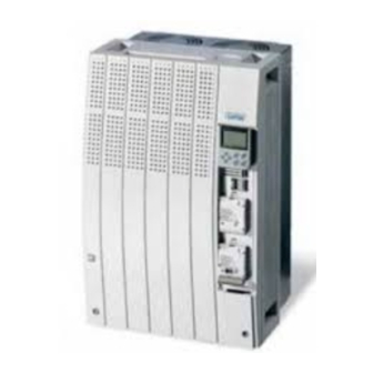
Preface The 8200 vector frequency inverter The 8200 vector frequency inverter The mains task of 8200 vector frequency inverters is the electronic speed The system adjustment of three-phase AC motors. Together with a Lenze geared motor or a Lenze three-phase AC motor the 8200 vector forms an electronic variable-speed drive and provides excellent drive features.
-
Page 6
Show/Hide Bookmarks… -
Page 7: How To Use This System Manual
Lenze motors, …) can be found in the corresponding catalogs, Operating Instructions and Manuals. The required documentation can be ordered at your Lenze sales partner or downloaded as PDF file from the internet. The System Manual is designed as a loose-leaf collection so that we are able to Paper or PDF inform you quickly and specifically about news and changes.
-
Page 8: Products To Which The System Manual Applies
D-31855 Aerzen D-31855 Aerzen D-31855 Aerzen D-31855 Aerzen E = Built-in unit ‚ ƒ ‚ ƒ ‚ ƒ ‚ ƒ Inverter Inverter Inverter Inverter 8200 vector 8200 vector 8200 vector 8200 vector Version: Version: Version: Version: Id.-No: Id.-No: Id.-No: Id.-No: Version:…
-
Page 9: Legal Regulations
Show/Hide Bookmarks Preface Legal regulations Legal regulations Labelling Lenze controllers are unambiguously designated by the contents of the nameplate. Manufacturer Lenze Drive Systems GmbH, Postfach 101352, D-31763 Hameln CE conformity Conforms to the EC Low-Voltage Directive 8200 vector frequency inverters and accessories…
-
Page 10
Manual. The specifications, processes, and circuitry described in this System Manual are for guidance only and must be adapted to your own application. Lenze does not take responsibility for the suitability of the process and circuit proposals. -
Page 11
Show/Hide Bookmarks Guide Contents Guide Contents Contents …………..2.1-1 Glossary . -
Page 12
Show/Hide Bookmarks… -
Page 13: Glossary
Function interface FIF interface, interface for function modules Any frequency inverter, servo inverter or DC controller Controller Lenze controller in combination with a geared motor, a Drive three-phase AC motor or other Lenze drive components. Subcode y of code Cxxxx Cxxxx/y (e.
-
Page 14: Meaning Of The Signal Names
Show/Hide Bookmarks Guide Glossary 2.2.2 Meaning of the signal names International Electrotechnical Commission International Protection Code National Electrical Manufacturers Association NEMA Verband deutscher Elektrotechniker Communauté Européene Underwriters Laboratories 2.2.2 Meaning of the signal names Automation interface input AIF-IN Function block AIF input Automation interface output AIF-OUT Function block AIF output…
-
Page 15
Show/Hide Bookmarks Guide Glossary Meaning of the signal names 2.2.2 Analog output 2 in AOUT2-IN Input of analog output 2 Analog output 2 offset AOUT2-OFFSET Offset of analog output 2 Analog output 2 out AOUT2-OUT Output of analog output 2 Digital control 1 DCTRL1 Function block device control… -
Page 16
Show/Hide Bookmarks Guide Glossary 2.2.2 Meaning of the signal names DCTRL1-speed output = 0 DCTRL1-NOUT=0 Status signal: Output frequency = 0 Hz DCTRL1-overheat warning DCTRL1-OH-WARN Warning signal: Overtemperature DCTRL1-warning: overheat or motor temperature or lost DCTRL1-OH-PTC-LP1-FAN1-WARN phase or fan failure Warning signal: Overtemperature or motor temperature too high or motor phase or fan have failed… -
Page 17
Show/Hide Bookmarks Guide Glossary Meaning of the signal names 2.2.2 DCTRL1-TRIP-reset DCTRL1-TRIP-RESET Fault message reset DCTRL1-external TRIP active DCTRL1-TRIP-SET Evaluation of external fault messages Digital frequency input 1 DFIN1 Function block frequency input 1 Digital frequency input 1 gain DFIN1-GAIN Gain of frequency input 1 Digital frequency input 1 normalisation DFIN1-NORM… -
Page 18
Show/Hide Bookmarks Guide Glossary 2.2.2 Meaning of the signal names MCTRL1-torque setpoint MCTRL1-MSET Torque setpoint or torque limiting value MCTRL1-torque setting 1 MCTRL1-MSET1 Torque threshold 1 MCTRL1-torque setting 1= actual torque MCTRL1-MSET1=MACT Torque threshold 1 is reached MCTRL1-torque setting 2 MCTRL1-MSET2 Torque threshold 2 MCTRL1-torque setting 2= actual torque… -
Page 19
Show/Hide Bookmarks Guide Glossary Meaning of the signal names 2.2.2 NSET1-activation of fixed frequency 2, 3, 6 or 7 NSET1-JOG2/3/6/7 Activates fixed setpoint (JOG) 2, 3, 6 or 7 NSET1-activation of fixed frequency 4, 5, 6 or 7 NSET1-JOG4/5/6/7 Activates fixed setpoint (JOG) 2, 3, 6 or 7 NSET1-speed setpoint 1 NSET1-N1 Main setpoint 1… -
Page 20
Show/Hide Bookmarks Guide Glossary 2.2.2 Meaning of the signal names PCTRL1-limit PCTRL1-LIM Status signal: Limitation of process controller output is reached PCTRL1-additional speed setpoint PCTRL1-NADD Additional setpoint PCTRL1- additional speed setpoint off PCTRL1-NADD-OFF Additional setpoint is switched off PCTRL1-speed minimum PCTRL1-NMIN Status signal: Minimum output frequency is reached… -
Page 21
Show/Hide Bookmarks Guide Glossary Meaning of the signal names 2.2.2 Relay 1 RELAY1 Relay 1 Relay 2 RELAY2 Relay 2 Ramp function generator Ramp function generator 2.2-9 EDS82EV903-1.0-11/2002… -
Page 22
Show/Hide Bookmarks… -
Page 23: Total Index
Show/Hide Bookmarks Guide Total index Total index 230 V controller, Mains connection, 6.4-4 Analog output signals, 10.12-4 400 V controller, Mains connection, 6.4-5, 6.6-4, Analog outputs, Configuration, 10.12-4 6.7-4, 6.8-4 Analog process data output words, Configuration, 87 Hz technology, 10.3-6 10.12-10 Application, as directed, 1.4-1 Application as directed, 1.4-1…
-
Page 24
Show/Hide Bookmarks Guide Total index Cable cross-section, Network of several drives, Bargraph display, Keypad E82ZBC, 9.3-3 12.4-6 Cable cross-sections Basic device, Installation, 5.1-1 — DC bus, 12.4-4 — Operation at rated power Basic device installation, 5.1-1 230 V, 4.3-4 400 V, 4.3-9 Basic settings, Own, 8.6-2, 10.17-2, 10.20-4 500 V, 4.3-14 — Operation with increased rated power… -
Page 25
Show/Hide Bookmarks Guide Total index Configuration Controller — Application as directed, 1.4-1 — Acceleration times and deceleration times, 10.7-1 — Labelling, 1.4-1 — Actual value selection, 10.8-1 — Analog input signals, 10.12-1 Controller inhibit, Drive performance, 10.5-1, 10.5-3 — Analog output signals, 10.12-4 Controller protection, 3.4-1 — Analog outputs, 10.12-4 Controlling the brake… -
Page 26
Show/Hide Bookmarks Guide Total index Deceleration time — Additional setpoint, 10.7-1, 10.20-20 e.l.c.bs, 6.2-4 — Process controller setpoint, 10.20-20 — Operation with, 6.2-4 Deceleration times, 10.7-1 E82ZBC keypad, 8.4-1, 9.3-1 Decentralised supply. Siehe DC-bus connection — Bargraph display, 9.3-3 — Calling up a password-protected function, 9.3-9 Default setting — Cancel password protection, 9.3-9 — load, 8.6-1, 10.17-1, 10.20-3… -
Page 27
Show/Hide Bookmarks Guide Total index Function keys, E82ZBC keypad, 9.3-4 Installation — electrical, 6.1-1 Function library, 10.1-1 — Keypad E82ZBC, 9.3-2 — Important notes, 10.2-1 — mechanical, 5.1-1, 7.2-1, 7.3-1, 7.4-1 , 5.3-6, 5.5-5 Fuses ”Cold plate” technique, 5.3-6, 5.4-4, 5.5-5 — Network of several drives, 12.4-6 ”Cold plate”technique 3 … -
Page 28
Show/Hide Bookmarks Guide Total index Mechanical installation, 5.1-1, 7.2-1, 7.3-1, 7.4-1 — ”Cold plate” technique, 5.3-6, 5.4-4, 5.5-5 Requirements on the cooler, 5.3-6, 5.4-4, 5.5-5 Labelling, Controller, 1.4-1 — ”Cold plate”technique 3 … 11 kW, 5.4-4 — DIN rail mounting 0.25 … 2.2 kW, 5.3-8 Layout of safety notes, 3.5-1 — Lateral mounting 0.25 … -
Page 29
Show/Hide Bookmarks Guide Total index Outputs — Analog, 10.12-4 — digital, 10.13-6 Network of several drives, 12.1-1 — Conditions, 12.4-1 Overpeeds, 3.4-1 — Function, 12.3-1 Overview, Accessories, 17.1-1 — Selection, 12.5-1 — Several drives, 12.1-1 — Supplies — 400 V devices, 12.5-4 Packaging, 4.2-1 Networking, 10.19-1 — Parallel operation of AIF and FIF interfaces, 10.19-3… -
Page 30
Show/Hide Bookmarks Guide Total index Process controller, 10.10-1 Relay output — Configuration, 10.13-6 — ”Debouncing” of digital output signal PCTRL1-LIM, 10.20-20 — Connection, 6.4-7, 6.5-7 — ”Debouncing” of digital output signal Reluctance motors, 1.4-1 PCTRL1-SET=ACT , 10.20-20 — Activation of inverse control, 10.20-21 Remote parameter setting — Actual root function value, 10.20-21 — Keypad EMZ9371BC, 9.4-9… -
Page 31
Show/Hide Bookmarks Guide Total index Signal flow diagram Switching window, Frequency setpoint reached, 10.20-19 — Controller state (STAT1, STAT2), 16.4-8 — Controller with application I/O, 16.3-3 System bus, Remote parameter setting using the E82ZBC keypad, 9.3-10 — Controller with Application I/O and communication module, 16.3-4 System description, 1.2-1 — Controller with communication module, 16.3-5… -
Page 32
Show/Hide Bookmarks Guide Total index Troubleshooting, 11.1-1, 11.2-1 V/f rated frequency, 10.3-5 — Drive performance in case of errors, 11.3-1 vector, Description, 1.2-1 — Error analysis with history buffer, 11.2-1 Vector control, 8.4-3, 8.5-2, 10.3-8 — Error messages, 11.4-1 — Maloperation of the drive, 11.4-1 Vibration resistance, 4.2-1 — Resetting error message, 11.5-1 Vmin boost, 10.3-7… -
Page 33: List Of Illustrations
….5.5-4 Fig. 5.5-5 Dimensions for 8200 vector in ”cold plate” technique 15 … 22 kW ….5.5-6 Fig.
-
Page 34
Show/Hide Bookmarks Guide List of illustrations Fig. 6.2-1 Wiring of the terminal strips ……… . . 6.2-6 Fig. -
Page 35
Show/Hide Bookmarks Guide List of illustrations Fig. 7.2-1 Worksteps …………7.2-1 Fig. -
Page 36
….. 13.4-11 Fig. 13.4-2 Connection of the brake resistor to 8200 vector 15 … 90 kW ….13.4-11 2.4-4… -
Page 37
Show/Hide Bookmarks Guide List of illustrations Fig. 15.2-1 Principle wiring of a pressure regulation ……..15.2-4 Fig. -
Page 38
Show/Hide Bookmarks… -
Page 39
……. . . 3.2-1 General safety and application notes for Lenze motors …… -
Page 40
Show/Hide Bookmarks… -
Page 41
Safety and application notes for Lenze controllers Safety and application notes for Lenze controllers (in conformity with the Low-Voltage Directive 73/23/EEC) Lenze controllers (frequency inverters, servo inverters, DC controllers) can General include live and rotating parts — depending on their type of protection — during operation. -
Page 42
Variant V004 of the controller series 9300 and 9300 vector, variant x4x of the Safe standstill controller series 8200 vector and axis module ECSxAxxx support the function ”Safe standstill”, protection against unintentional restart, according to the requirements of Appendix I, No. 1.2.7 of the EC Directive ”Machinery” 98/37/EG, DIN EN 954-1 category 3 and DIN EN 1037. -
Page 43
Show/Hide Bookmarks Safety information Safety and application notes for Lenze controllers Recycle metals and plastics. Dispose of printed board assemblies according to Disposal the state of the art. The product-specific safety and application notes in these instructions must also be observed! 3.2-3… -
Page 44
Show/Hide Bookmarks… -
Page 45
Show/Hide Bookmarks Safety information General safety and application notes for Lenze motors General safety and application notes for Lenze motors (in comformity with the Low-Voltage Directive 73/23/EEC) Low-voltage machines have dangerous, live and rotating parts as well as possibly General hot surfaces. -
Page 46
Show/Hide Bookmarks Safety information General safety and application notes for Lenze motors Ensure an even surface, solid foot or flange mounting and exact alignment if a Installation direct clutch is connected. Avoid resonances with the rotational frequency and double mains frequency which may be caused during assembly. Turn rotor by hand, listen for unusual slipping noises. -
Page 47
Show/Hide Bookmarks Safety information General safety and application notes for Lenze motors ≤ 3.5 mm/s (P ≤ 15 kW) and 4.5 mm/s (P Vibration severities v > 15 kW) are Operation acceptable when the clutch is activated. If deviations from normal operation occur, e.g. -
Page 48
Show/Hide Bookmarks… -
Page 49
Show/Hide Bookmarks Safety information Residual hazards Residual hazards Before working on the controller check that no voltage is applied to the Protection of persons power terminals, the relay output and the pins of the FIF interface, – because the power terminals U, V, W, +UG, -UG, BR1 and BR2 remain live for at least 3 minutes after mains switch-off. -
Page 50
Show/Hide Bookmarks… -
Page 51
Show/Hide Bookmarks Safety information Layout of safety notes Layout of safety notes All safety information given in these Instructions have got the same layout: Pictograph (indicates the type of danger) Signal word! (indicates the severity of danger) Note (describes the danger and explains how to avoid it) Pictograph Possible consequences if Signal word… -
Page 52
Show/Hide Bookmarks… -
Page 53
Show/Hide Bookmarks Technical data Contents Technical data Contents Contents …………..4.1-1 General data/application conditions . -
Page 54
Show/Hide Bookmarks… -
Page 55: General Data/Application Conditions
Show/Hide Bookmarks Technical data General data/application conditions General data/ application conditions Conformity Low-Voltage Directive (73/23/EEC) Standards and application Approvals UL 508C Underwriter Laboratories (File-No. E132659) conditions Power Conversion Equipment Max. permissible motor For rated mains voltage and chopper frequency of 8 kHz without additional output cable length filters shielded…
-
Page 56
Permissible mains types Operation at TT systems, TN systems or systems with grounded star point without additional measures Operation at IT systems is only possible with variant ”1xx” of the 8200 vector basic devices 15 … 90 kW Operation in public supply… -
Page 57
Show/Hide Bookmarks Technical data General data/application conditions Control types V/f characteristic control (linear/square-law), vector control, torque selection Control Chopper frequency 0.25 … 11 kW 2 kHz, 4 kHz, 8 kHz, 16 kHz with optimised noise level 15 … 90 kW 1 kHz, 2 kHz, 4 kHz, 8 kHz, 16 kHz, optionally with optimised noise level or optimised power loss Torque characteristic… -
Page 58
Show/Hide Bookmarks Technical data General data/application conditions Analog inputs Inputs and outputs Analog outputs With standard I/O With standard I/O 1 input, optionally bipolar 1 output With application I/O With application I/O 2 inputs, optionally bipolar 2 inputs, optionally bipolar Digital inputs Digital outputs With standard I/O… -
Page 59: Operation With Rated Power (Normal Operation)
120 x 60 x 140 Weight m [kg] Printed in bold = Data for operation at 8 kHz chopper frequency (Lenze setting) Currents for periodic load change: 1 min overcurrent with I and 2 min basic load with 75 % I Chopper frequency is reduced to 4 kHz if ϑ…
-
Page 60: Rated Data For Mains Voltage 500 V
240 x 60 x 140 Weight m [kg] Printed in bold = Data for operation at 8 kHz chopper frequency (Lenze setting) Operation only with mains choke For operation with power-adapted motors additional power to be taken from the DC bus…
-
Page 61: Rated Data For Mains Voltage 230 V
240 x 125 x 140 Weight m [kg] Printed in bold = Data for operation at 8 kHz chopper frequency (Lenze setting) Operation only with mains choke For operation with power-adapted motors additional power to be taken from the DC bus…
-
Page 62
4.3.1 Rated data for mains voltage 230 V Operation without mains choke Fuses and cable cross-sections Installation to EN 60204-1 Installation to UL (operation with rated power, 8200 vector Mains ‚ L1, L2, L3, L1, L2, L3, mains voltage 230 V) -
Page 63
Weight m [kg] Printed in bold = Data for operation at 8 kHz chopper frequency (Lenze setting) For operation with power-adapted motors additional power to be taken from the DC bus Currents for periodic load change: 1 min overcurrent with I and 2 min basic load with 75 % I Chopper frequency is reduced to 4 kHz if ϑ… -
Page 64
240 x 125 x 140 Weight m [kg] Printed in bold = Data for operation at 8 kHz chopper frequency (Lenze setting) Operation only with mains choke For operation with power-adapted motors additional power to be taken from the DC bus… -
Page 65
[kg] Printed in bold = Data for operation at 8 kHz chopper frequency (Lenze setting) Operation only with mains choke or mains filter For operation with power-adapted motors additional power to be taken from the DC bus… -
Page 66
[kg] Printed in bold = Data for operation at 8 kHz chopper frequency (Lenze setting) Operation only with mains choke or mains filter For operation with power-adapted motors additional power to be taken from the DC bus… -
Page 67
Rated data for mains voltage 400 V 4.3.2 Operation without mains choke Fuses and cable cross-sections Installation to EN 60204-1 Installation to UL (operation with rated power, 8200 vector mains ‚ L1, L2, L3, L1, L2, L3, mains voltage 400 V) -
Page 68
Weight m [kg] Printed in bold = Data for operation at 8 kHz chopper frequency (Lenze setting) For operation with power-adapted motors additional power to be taken from the DC bus Currents for periodic load change: 1 min overcurrent with I and 2 min basic load with 75 % I Chopper frequency is reduced to 4 kHz if ϑ… -
Page 69
240 x 125 x 140 Weight m [kg] Printed in bold = Data for operation at 8 kHz chopper frequency (Lenze setting) Operation only with mains choke For operation with power-adapted motors additional power to be taken from the DC bus… -
Page 70
[kg] Printed in bold = Data for operation at 8 kHz chopper frequency (Lenze setting) Operation only with mains choke or mains filter For operation with power-adapted motors additional power to be taken from the DC bus… -
Page 71
[kg] Printed in bold = Data for operation at 8 kHz chopper frequency (Lenze setting) Operation only with mains choke or mains filter For operation with power-adapted motors additional power to be taken from the DC bus… -
Page 72: Mains Voltage 500 V
4.3.3 Rated data for mains voltage 500 V Operation without mains choke Fuses and cable cross-sections Installation to EN 60204-1 Installation to UL (operation with rated power, 8200 vector mains ‚ L1, L2, L3, L1, L2, L3, mains voltage 500 V)
-
Page 73
0.75 Three phase AC asynchronous motor Three-phase AC asynchronous motor [hp] (4 pole) E82EV251K2C0xx E82EV551K2C0xx E82EV751K2C0xx E82EV152K2C0xx 8200 vector type EMC filter integrated Without EMC filter E82EV251K2C2xx E82EV551K2C2xx E82EV751K2C2xx E82EV152K2C2xx Mains voltage 1/N/PE AC 180 V — 0 % … 264 V + 0 % ; 45 Hz — 0 % … 65 Hz + 0 % mains 3/PE AC 100 V — 0 % … -
Page 74
4.4.1 Rated data for mains voltage 230 V Maximum motor power [kW] Three phase AC asynchronous motor Three-phase AC asynchronous motor [hp] 10.2 (4 pole) 8200 vector type EMC filter E82EV302K2C0xx E82EV552K2C0xx integrated Without EMC filter E82EV302K2C2xx E82EV552K2C2xx Mains voltage 3/PE AC 100 V — 0 % … -
Page 75
Rated data for mains voltage 230 V 4.4.1 Operation without mains choke Fuses and cable cross-sections Installation to EN 60204-1 Installation to UL (operation with increases rated 8200 vector Mains ‚ L1, L2, L3, L1, L2, L3, power, mains voltage 230 V) -
Page 76
4.4.2 Rated data for mains voltage 400 V [kW] 0.75 Maximum motor power Three phase AC asynchronous motor Three-phase AC asynchronous motor [hp] (4 pole) 8200 vector type EMC filter E82EV551K4C0xx E82EV751K4C0xx E82EV222K4C0xx integrated E82EV551K4C2xx E82EV751K4C2xx E82EV222K4C2xx Without EMC filter Mains voltage 3/PE AC 320 V — 0 % … -
Page 77
Operation with increased rated power Rated data for mains voltage 400 V 4.4.2 Maximum motor power [kW] Three phase AC asynchronous motor Three-phase AC asynchronous motor [hp] (4 pole) 8200 vector type EMC filter E82EV302K4C0xx E82EV402K4C0xx E82EV752K4C0xx integrated Without EMC filter E82EV302K4C2xx E82EV402K4C2xx… -
Page 78
4.4.2 Rated data for mains voltage 400 V Maximum motor power [kW] Three phase AC asynchronous motor Three-phase AC asynchronous motor [hp] (4 pole) 8200 vector type 8200 vector type With mains filter E82EV153K4B3xx E82EV223K4B3xx 1) 4) E82EV153K4B2xx E82EV223K4B2xx E82EV303K4B2xx… -
Page 79
Rated data for mains voltage 400 V 4.4.2 Typical motor power [kW] Three phase AC asynchronous motor Three-phase AC asynchronous motor [hp] (4 pole) 8200 vector type 8200 vector type With mains filter E82EV553K4B3xx 1) 4) 1) 4) E82EV453K4B2xx E82EV553K4B2xx… -
Page 80
4.4.2 Rated data for mains voltage 400 V Operation without mains choke Fuses and cable cross-sections Installation to EN 60204-1 Installation to UL (operation with increased rated 8200 vector Mains ‚ L1, L2, L3, L1, L2, L3, power, mains voltage 400 V) -
Page 81
Show/Hide Bookmarks Technical data Operation with increased rated power Mains voltage 500 V 4.4.3 4.4.3 Mains voltage 500 V The operation with increased rated power is not possible for 500 V rated mains voltage. 4.4-9 EDS82EV903-1.0-11/2002… -
Page 82
Show/Hide Bookmarks… -
Page 83
Show/Hide Bookmarks Basic device installation Contents Basic device installation Contents Contents …………..5.1-1 Important notes . -
Page 84
Show/Hide Bookmarks… -
Page 85: Important Notes
Basic device installation Important notes Important notes 8200 vector frequency inverters should only be used as built-in units If the cooling air contains pollutants (dust, fluff, grease, aggressive gases) ensure suitable measures to protect the inverter (e.g. filters, regular cleaning, etc.) Free space: –…
-
Page 86
Show/Hide Bookmarks… -
Page 87: Basic Units In The Power Range 0.25
Mounting with fixing rails (standard) 5.3.1 Basic units in the power range 0.25 … 2.2 kW 5.3.1 Mounting with fixing rails (standard) 8200 vector 0.25 … 2.2 kW 4 Nm 35 lbin 28200vec004 Fig. 5.3-1 Standard mounting with fixing rails 0.25 … 2.2 kW…
-
Page 88: Fig. 5.3-2 Dimensions For Thermally Separated Mounting 0.25
Thermally separated mounting (push-through technique) For mounting in push-through technique use the controller type E82 D V..The delivery package includes all parts and components required for mounting. 8200 vector 0.25 … 0.75 kW 8200vec027 Fig. 5.3-2 Dimensions for thermally separated mounting 0.25 … 0.75 kW…
-
Page 89: Fig. 5.3-3 Thermally Separated Mounting 0.25
Push the grounding terminals with the correct end onto the fixing frame: – The contact springs must point to the rear panel of the control cabinet – The cutouts of the seal determine the positions Insert the 8200 vector into the cutout Fasten it with 8 M4x10 screws 5.3-3…
-
Page 90: Fig. 5.3-4 Dimensions For Thermally Separated Mounting 1.5
Show/Hide Bookmarks Basic device installation Basic units in the power range 0.25 … 2.2 kW 5.3.2 Thermally separated mounting (push-through technique) 8200 vector 1.5 … 2.2 kW 8200vecxxx Fig. 5.3-4 Dimensions for thermally separated mounting 1.5 … 2.2 kW Fixing frames…
-
Page 91: Fig. 5.3-5 Thermally Separated Mounting 1.5
Push the grounding terminals with the correct end onto the fixing frame: – The contact springs must point to the rear panel of the control cabinet – The cutouts of the seal determine the positions Insert the 8200 vector into the cutout Fasten it with 8 M4x10 screws 5.3-5…
-
Page 92
– The cooler and heatsink must be attached using all the screwed joints that are specified. Thermal resistance R according to table. The values are valid for operation with the drive controllers under rated conditions. 8200 vector Cooling path Ground Power to be dissipated Heatsink — environment Type [°C/W]… -
Page 93: Fig. 5.3-6 Dimensions For Mounting In «Cold Plate» Technique 0.25
Show/Hide Bookmarks Basic device installation Basic units in the power range 0.25 … 2.2 kW Mounting in ”cold plate” technique 5.3.3 8200 vector 0.25 … 2.2 kW 4 Nm 35 lbin 8200vec029 Fig. 5.3-6 Dimensions for mounting in ”Cold plate” technique 0.25 … 2.2 kW…
-
Page 94: Fig. 5.3-7 Din Rail Mounting 0.25
This mounting variant does not enable a CE-typical drive system to be installed. The accessories for DIN rail mounting are not included in the delivery package. Order number: E82ZJ002 for 8200 vector 0.25 … 2.2 kW 820vec025 Fig. 5.3-7 DIN rail mounting 0.25 … 2.2 kW …
-
Page 95: Fig. 5.3-8 Fixed Lateral Mounting
The controllers 0.25 … 0.75 kW can be mounted with the rails included in Fixed lateral mounting the delivery package. The controllers 1.5 … 2.2 kW require a mounting kit. – Order number E82ZJ001 for 8200 vector 1.5 … 2.2 kW 8200vec074 Fig. 5.3-8 Fixed lateral mounting …
-
Page 96: Fig. 5.3-9 Swivelling Lateral Mounting
Basic units in the power range 0.25 … 2.2 kW 5.3.5 Lateral mounting All controllers require a mounting kit: Swivelling lateral mounting – Order number E82ZJ001 for 8200 vector 0.25 … 2.2 kW 8200vec024 Fig. 5.3-9 Swivelling lateral mounting …
-
Page 97: Fig. 5.4-1 Standard Mounting With Fixing Rails 3
5.4.1 Basic units in the power range 3 … 11 kW 5.4.1 Mounting with fixing rails (standard) 8200 vector 3 … 11 kW 8200vec060 Fig. 5.4-1 Standard mounting with fixing rails 3 … 11 kW Different sizes can only be mounted side by side when the smaller units are…
-
Page 98: Fig. 5.4-2 Dimensions For Thermally Separated Mounting 3
Thermally separated mounting (push-through technique) For mounting in push-through technique use the controller type E82 D V..The delivery package includes all parts and components required for mounting. 8200 vector 3 … 11 kW 8200vec327 Fig. 5.4-2 Dimensions for thermally separated mounting 3 … 11 kW…
-
Page 99: Fig. 5.4-3 Dimensions For Thermally Separated Mounting Cutout 3
Push the grounding terminals with the correct end onto the fixing frame: – The contact springs must point to the rear panel of the control cabinet – The cutouts of the seal determine the positions Insert the 8200 vector into the cutout Fasten it with 4 M4x10 screws Dimensions [mm]…
-
Page 100
– The cooler and heatsink must be attached using all the screwed joints that are specified. Thermal resistance R according to table. The values are valid for operation with the drive controllers under rated conditions. 8200 vector Cooling path Ground Power to be dissipated Heatsink — environment Type [°C/W]… -
Page 101: Fig. 5.4-4 Dimensions For Mounting In «Cold Plate» Technique 3
Show/Hide Bookmarks Basic device installation Basic units in the power range 3 … 11 kW Mounting in ”cold plate” technique 5.4.3 8200 vector 3 … 11 kW 4 Nm 35 lbin 8200vecxxx Fig. 5.4-4 Dimensions for mounting in ”cold plate” technique 3 … 11 kW…
-
Page 102: Fig. 5.4-5 Fixed Lateral Mounting
Fixed lateral mounting All controllers require a mounting kit: – Order number E82ZJ005 for 8200 vector 3 … 4 kW (230 V) – Order number E82ZJ006 for 8200 vector 5.5 … 7.5 kW (230 V) – Order number E82ZJ005 for 8200 vector 3 … 5.5 kW (400/500 V) –…
-
Page 103: Fig. 5.4-6 Swivelling Lateral Mounting
All controllers require a mounting kit: Swivelling lateral mounting – Order number E82ZJ005 for 8200 vector 3 … 4 kW (230 V) – Order number E82ZJ006 for 8200 vector 5.5 … 7.5 kW (230 V) – Order number E82ZJ005 for 8200 vector 3 … 5.5 kW (400/500 V) –…
-
Page 104
Show/Hide Bookmarks… -
Page 105: Fig. 5.5-1 Standard Mounting With Mains Choke 15
the housing cover. ‚ Mounting of the fixing brackets ƒ Dimensions Drive controllers can be mounted side by side without a certain space to each other. Dimensions [mm] 8200 vector Mains choke E82EV153K4B2x1 ELN3-0088H035 E82EV223K4B2x1 ELN3-0075H045 E82EV303K4B2x1 ELN3-0055H055 5.5-1…
-
Page 106: Fig. 5.5-2 Standard Mounting With Footprint Mains Filter 15
‚ Mounting of the fixing brackets ƒ Dimensions Mount the drive controllers side by side with a certain space to each other in order to dismount lifting-eye bolts, if necessary. Dimensions [mm] 8200 vector E82EV153K4B3xx E82EV223K4B3xx E82EV303K4B3xx 5.5-2 EDS82EV903-1.0-11/2002…
-
Page 107: Fig. 5.5-3 Standard Mounting With Built-On Mains Filter 15
Mount the drive controllers side by side with a certain space to each other in order to dismount lifting-eye bolts, if necessary. Mains filter Mains filter Dimensions [mm] type A or type B 8200 vector E82EV153K4B2x1 EZN3x0110H030 250 680 365 205 250 680 365 205 705 250…
-
Page 108: Fig. 5.5-4 Dimensions For Thermally Separated Mounting 15
For mounting in push-through technique use the controller type E82 D V..The delivery package includes all parts and components required for mounting. 8200vec304 Fig. 5.5-4 Dimensions for thermally separated mounting 15 … 30 kW Dimensions [mm] 8200 vector E82DV153K4B E82DV223K4B 279.5 250 379.5 350 279.5 250 379.5 350 131 261.5 361.5 131 261.5 361.5…
-
Page 109: Mounting In «Cold Plate» Technique
– The cooler and heatsink must be attached using all the screwed joints that are specified. Thermal resistance R according to table. The values are valid for operation with the drive controllers under rated conditions. 8200 vector Cooling path Ground Power to be dissipated Heatsink — environment Type [°C/W]…
-
Page 110: Fig. 5.5-5 Dimensions For 8200 Vector In «Cold Plate» Technique 15
Basic units in the power range 15 … 30 kW 5.5.5 Mounting in ”cold plate” technique Without mains filter 8200vec301 Fig. 5.5-5 Dimensions for 8200 vector in ”cold plate” technique 15 … 22 kW Dimensions [mm] 8200 vector E82CV153K4B E82CV223K4B 5.5-6…
-
Page 111: Fig. 5.5-6 Dimensions For 8200 Vector In «Cold Plate» Technique 15
Basic units in the power range 15 … 30 kW Mounting in ”cold plate” technique 5.5.5 With mains filter 8200vec299 Fig. 5.5-6 Dimensions for 8200 vector in ”cold plate” technique 15 … 22 kW Dimensions [mm] 8200 vector E82CV153K4B E82CV223K4B Dimensions [mm]…
-
Page 112
Show/Hide Bookmarks… -
Page 113: Basic Units In The Power Range 45
Loose both screws in order to remove the housing cover. ‚ Mounting of the fixing brackets ƒ Dimensions Mount the drive controllers side by side leaving a certain space for dismounting the lifting-eye bolt. Dimensions [mm] 8200 vector Mains choke E82EV453K4B2x1 ELN3-0038H085 E82EV553K4B2x1 ELN3-0027H105 5.6-1 EDS82EV903-1.0-11/2002…
-
Page 114: Fig. 5.6-2 Standard Mounting With Footprint Mains Filter 45
Loose both screws in order to remove the housing cover. ‚ Mounting of the fixing brackets ƒ Dimensions Mount the drive controllers side by side leaving a certain space for dismounting the lifting-eye bolt. Dimensions [mm] 8200 vector E82EV453K4B3xx E82EV553K4B3xx 5.6-2 EDS82EV903-1.0-11/2002…
-
Page 115: Fig. 5.6-3 Standard Mounting With Built-On Mains Filter
Dimensions Mount the drive controllers side by side leaving a certain space for dismounting the lifting-eye bolt. Mains filter Mains filter Dimensions [mm] type A or type B 8200 vector E82EV453K4B EZN3x0037H090 973 508 284 973 508 284 1050 1050…
-
Page 116: Fig. 5.6-4 Dimensions For Thermally Separated Mounting 45
8200vec302 Fig. 5.6-4 Dimensions for thermally separated mounting 45 … 55 kW Dimensions [mm] 8200 vector E82DV453K4B 92 5 172 5 265 92.5 172.5 265 285 163 5 285 163.5…
-
Page 117: Mounting With Fixing Brackets And Mains Choke (Standard)
Loose both screws in order to remove the housing cover. ‚ Mounting of the fixing brackets ƒ Dimensions Mount the drive controllers side by side leaving a certain space for dismounting the lifting-eye bolt. Dimensions [mm] 8200 vector Mains choke E82EV753K4B2x1 E82EV903K4B2x1 ELN3-0017H170 30.5 5.7-1 EDS82EV903-1.0-11/2002…
-
Page 118: Fig. 5.7-2 Standard Mounting With Footprint Mains Filter 75
Loose both screws in order to remove the housing cover. ‚ Mounting of the fixing brackets ƒ Dimensions Mount the drive controllers side by side leaving a certain space for dismounting the lifting-eye bolt. Dimensions [mm] 8200 vector E82EV753K4B3xx E82EV903K4B3xx 30.5 5.7-2 EDS82EV903-1.0-11/2002…
-
Page 119: Mounting With Fixing Brackets And Built-On Mains Filter (Mounting Variant 1)
ƒ Dimensions Mount the drive controllers side by side leaving a certain space for dismounting the lifting-eye bolt. Mains filter Mains filter Dimensions [mm] type A or type B 8200 vector E82EV753K4B2x1 EZN3x0022H150 1000 1000 30 5 30.5 207 5 207.5…
-
Page 120: Fig. 5.7-4 Standard Mounting With Built-On Mains Filter 75
Dimensions Mount the drive controllers side by side leaving a certain space for dismounting the lifting-eye bolt. Mains filter Mains filter Dimensions [mm] type A or type B 8200 vector E82EV753K4B2x1 EZN3x0022H150 30 5 30.5 1000 1000 E82EV903K4B2x1 EZN3x0017H200 5.7-4…
-
Page 121: Fig. 5.7-5 Dimensions For Thermally Separated Mounting 75
For mounting in push-through technique use the controller type E82 D V..The delivery package includes all parts and components required for mounting. 8200vec303 Fig. 5.7-5 Dimensions for thermally separated mounting 75 … 90 kW Dimensions [mm] 8200 vector E82DV753K4B E82DV903K4B 172.5 295.5 419 285 163.5 Mounting cutout in the control cabinet…
-
Page 122
Show/Hide Bookmarks… -
Page 123
Show/Hide Bookmarks Basic unit wiring Contents Basic unit wiring Contents Contents …………..6.1-1 Important notes . -
Page 124
Show/Hide Bookmarks Basic unit wiring Contents Basic units in the power range 15 … 30 kW ……..6.6-1 6.6.1 Wiring according to EMC (installation of a CE-typical drive system) -
Page 125: Important Notes
Show/Hide Bookmarks Basic unit wiring Important notes Protection of persons 6.2.1 Important notes ( ( ( ( Stop! The drive controller contains electrostatically sensitive components! The personnel must be free of electrostatic charge prior to assembly and service operations. 6.2.1 Protection of persons Danger! Before working on the controller check that no voltage is applied…
-
Page 126: Motor Protection
– By overcurrent relays or temperature monitoring – We recommend PTC thermistors or thermal contacts to monitor the motor temperature. (Lenze three-phase AC motors are all equipped with thermal contacts (NC contacts) – PTCs or thermal contacts can be connected to the controller.
-
Page 127: Operation On Public Mains (Compliance With En 61000-3-2)
If you observe all measures stated, the controllers do not exceed the limit values according to EN 61000-3-2. The machine/system manufacturer is responsible for the compliance with the regulations of the machine: Connection voltage Power Measure 8200 vector [kW] E82EV251K2C 0.25 Use assigned mains choke Use assigned mains choke E82EV371K2C 0.37…
-
Page 128: Operation With E.l.c.bs (Earth-Leakage Circuit-Breakers)
Show/Hide Bookmarks Basic unit wiring Important notes 6.2.5 Operation with e.l.c.bs (earth-leakage circuit-breakers) 6.2.5 Operation with e.l.c.bs (earth-leakage circuit-breakers) Danger! The controllers have an internal mains rectifier. In the event of a short-circuit to frame, a DC fault current can prevent the activation of the AC-sensitive or pulse-current sensitive e.l.c.b.
-
Page 129: Specification Of Cables Used
Specification of cables used The cables used must comply with the approvals required for the Power connections application (e.g. UL). Use low-capacitance motor cables: 8200 vector power range 8200 vector power range Capacitance per unit length Core/core Core/shield ≤ 75 pF/m 0.25 …
-
Page 130: Fig. 6.2-1 Wiring Of The Terminal Strips
Show/Hide Bookmarks Basic unit wiring Important notes 6.2.8 Wiring of terminal strips 6.2.8 Wiring of terminal strips The enclosed terminal strips are tested according to the specifications of the DIN VDE 0627:1986-06 (partially) DIN EN 60999:1994-04 (partially) Checked and tested are, for instance, mechanical, electrical and thermal load, vibration, damage of conductors, loose conductors, corrosion, ageing.
-
Page 131: Basics For Wiring According To Emc
Show/Hide Bookmarks Basic unit wiring Basics for wiring according to EMC Requirements on the cables 6.3.1 Basics for wiring according to EMC 6.3.1 Requirements on the cables Motor cable design Only use shielded, four-core motor cable (core U, V, W, PE and overall shield).
-
Page 132: Fig. 6.3-1 Shielding Of The Motor Cable
Show/Hide Bookmarks Basic unit wiring Basics for wiring according to EMC 6.3.2 Shielding 6.3.2 Shielding Requirements The quality of shielding is determined by: a good shield connection – a contact surface as large as possible a low resistance: – Only use shields with tin-plated or nickel-plated copper braids! Wiring technique Always connect the shield to the conductive and grounded mounting plate with a surface as large as possible via a conductive clamp.
-
Page 133: Fig. 6.3-2 Shielding Of Long, Analog Control Cables
Show/Hide Bookmarks Basic unit wiring Basics for wiring according to EMC Installation in the control cabinet 6.3.3 The cables of the analog and digital inputs and outputs must be shielded. If Control cables short (up to 200 mm), unshielded cables are used, they must be twisted. In case of the analog cables the shield must be connected to one side of the controller.
-
Page 134
Show/Hide Bookmarks Basic unit wiring Basics for wiring according to EMC 6.3.3 Installation in the control cabinet Control cables and mains cables must be separated from the motor cable. Optimum cable routing Install separate terminals for the motor cables at the control cabinet entry with a minimum distance from the other terminals of at least 100 mm. -
Page 135: Fig. 6.3-3 Cable Routing In The Control Cabinet
Show/Hide Bookmarks Basic unit wiring Basics for wiring according to EMC Installation in the control cabinet 6.3.3 Separation of the “hot” motor cable from control cables, signal cables and mains Continuation of cable routing cables: Never lay motor cables and signal cables in parallel. Crossings must be layed at right angles.
-
Page 136: Fig. 6.3-4 Cable Routing In The Cable Duct With Barrier
Show/Hide Bookmarks Basic unit wiring Basics for wiring according to EMC 6.3.4 Wiring outside the control cabinet 6.3.4 Wiring outside the control cabinet Notes for cable laying outside the control cabinet: The longer the cables the greater must be the space between the cables. In case of parallel cable routing of cables with different types of signals it is possible to minimise the interferences by means of a metal barrier or separated cable ducts.
-
Page 137
Show/Hide Bookmarks Basic unit wiring Basics for wiring according to EMC Wiring outside the control cabinet 6.3.4 It is possible to connect the controller, mains choke or RFI filter to the mains Wiring on the mains side via single cores or unshielded cables. The cable cross-section must be rated for the assigned fuse protection (VDE 0160). -
Page 138
Show/Hide Bookmarks… -
Page 139: Basic Units In The Power Range 0.25
Show/Hide Bookmarks Basic unit wiring Basic units in the power range 0.25 … 2.2 kW Basic units in the power range 0.25 … 2.2 kW This page remains blank to give you a clearly arranged overview of the following subject on the next double page. 6.4-1 EDS82EV903-1.0-11/2002…
-
Page 140: Wiring According To Emc (Installation Of A Ce-Typical Drive System)
Show/Hide Bookmarks Basic unit wiring Basic units in the power range 0.25 … 2.2 kW 6.4.1 Wiring according to EMC (installation of a CE-typical drive system) 6.4.1 Wiring according to EMC (installation of a CE-typical drive system) Drives comply with the EMC Directive if they are installed according to the guidelines for CE-typical drive systems.
-
Page 141: Basic Units In The Power Range 45
Show/Hide Bookmarks Basic unit wiring Basic units in the power range 0.25 … 2.2 kW Wiring according to EMC (installation of a CE-typical drive system) 6.4.1 Realisation L < 40 mm L < 500 mm 58200vec008 Fig. 6.4-1 Wiring in compliance with EMC standards Mounting plate with electrically conductive surface Control cable to function module, connect the shielding to the EMC shield sheet (PES) with a surface as large as possible…
-
Page 142: Fig. 6.4-2 Mains Connection 230/240 V 0.25
1/N/PE AC 180 … 264 V or 3/PE AC 100 … 264 V. Higher mains voltages will destroy the controller! The discharge current to PE is > 3.5 mA. EN 50178 requires a fixed installation. Double PE connection required. 8200 vector 0.25 … 2.2 kW E82EV251K2B E82EV371K2B X1.1…
-
Page 143: Fig. 6.4-3 Mains Connection 400/500 V 0.55
3/PE AC 320 … 500 V. Higher mains voltages will destroy the controller! The discharge current to PE is > 3.5 mA. EN 50178 requires a fixed installation. Double PE connection required. 8200 vector 0.55 … 2.2 kW E82EV551K4B E82EV751K4B E82EV152K4B X1.1…
-
Page 144: Fig. 6.4-4 Motor Connection 0.25
The shorter the motor cables, the better the drive response! HF-shield end by PE connection through shield bracket or EMC cable connection. X2.1/PE Earthing of the 8200 vector at the output side X2.1/BR1, Connection terminals for the brake resistor X2.1/BR2 (For information about the operation with brake resistor see the Operating Instructions) X2.2/T1,…
-
Page 145: Relay Output Connection
If you control a holding brake at the motor with the relay output, a spark suppressor must be used in case of DC switching: Universal spark suppressor for 24 V DC brake, 6-pole Lenze brake rectifier for 180 V/205 V DC brake. 6.4-7 EDS82EV903-1.0-11/2002…
-
Page 146
Show/Hide Bookmarks… -
Page 147: Basic Units In The Power Range 3
Show/Hide Bookmarks Basic unit wiring Basic units in the power range 3 … 11 kW Basic units in the power range 3 … 11 kW This page remains blank to give you a clearly arranged overview of the following subject on the next double page. 6.5-1 EDS82EV903-1.0-11/2002…
-
Page 148: Wiring According To Emc (Installation Of A Ce-Typical Drive System)
Show/Hide Bookmarks Basic unit wiring Basic units in the power range 3 … 11 kW 6.5.1 Wiring according to EMC (installation of a CE-typical drive system) 6.5.1 Wiring according to EMC (installation of a CE-typical drive system) Drives comply with the EMC Directive if they are installed according to the guidelines for CE-typical drive systems.
-
Page 149
Show/Hide Bookmarks Basic unit wiring Basic units in the power range 3 … 11 kW Wiring according to EMC (installation of a CE-typical drive system) 6.5.1 Realisation L < 40 mm L < 500 mm 88200vec066 Fig. 6.5-1 Wiring in compliance with EMC standards Mounting plate with electrically conductive surface Control cable to function module, connect the shielding to the EMC shield sheet (PES) with a surface as large as possible… -
Page 150: Fig. 6.5-2 Mains Connection 230/240 V 3
264 V. Higher mains voltages will destroy the controller! The discharge current to PE is > 3.5 mA. EN 50178 requires a fixed installation. Double PE connection required. 8200 vector 3 … 7.5 kW X1.1 3 PE AC 230/240 V 45Hz -0%…65Hz +0% 100 V -0%…264 V +0%…
-
Page 151: Power Connections For 400 V Mains Voltage
The discharge current to PE is > 3.5 mA. EN 50178 requires a fixed installation. Double PE connection required. 8200 vector 3 … 11 kW X1.1 3 PE AC 400 V 45 Hz -0 %…65 Hz +0 % 320 V -0 %…550 V +0 % 0,7…0,8 Nm…
-
Page 152: Fig. 6.5-4 Motor Connection 3
The shorter the motor cables, the better the drive response! HF-shield end by PE connection through shield bracket or EMC cable connection. X2.1/PE Earthing of the 8200 vector at the output side X2.1/BR1, Connection terminals for the brake resistor X2.1/BR2 (For information about the operation with brake resistor see the Operating Instructions) X2.2/T1,…
-
Page 153: Relay Output Connection
If you control a holding brake at the motor with the relay output, a spark suppressor must be used in case of DC switching: Universal spark suppressor for 24 V DC brake, 6-pole Lenze brake rectifier for 180 V/205 V DC brake. 6.5-7 EDS82EV903-1.0-11/2002…
-
Page 154
Show/Hide Bookmarks… -
Page 155
Show/Hide Bookmarks Basic unit wiring Basic units in the power range 15 … 30 kW Basic units in the power range 15 … 30 kW Drives comply with the EMC Directive if they are installed according to the guidelines for CE-typical drive systems. The user is responsible for the compliance of his application with the EC directives. -
Page 156: Fig. 6.6-1 Wiring According To Emc Requirements 15
J RB -UG +UG PE RB1 RB2 9352 PE L1 L2 L3 K21 K22 K24 34 33 K32 K11 K12 K14 FIF I FIF II 8200 vector E82ZAFx E82ZAFS GND2 (15kW … 90kW) (PT E82ZAFS100) +20V +20V GND2 GND1 GND1…
-
Page 157
Show/Hide Bookmarks Basic unit wiring Basic units in the power range 15 … 30 kW Wiring according to EMC (installation of a CE-typical drive system) 6.6.1 Fuses K1 Mains contactor PES HF shield termination through large-surface connection to PE Z1 Mains filters/mains chokes Z2 Brake resistor Z3 Brake chopper Relay connection K1… -
Page 158: Fig. 6.6-2 Mains Connection 15
Connection with built-on mains filter Connection brake chopper ( ^ Operating Instructions for the brake chopper ) Connection of temperature monitoring for mains filter (thermal contact) Z1 Mains choke/mains filter Fuses and cable cross-sections 8200 vector 8200 vector Mains Mains Installation to EN 60204-1…
-
Page 159
Show/Hide Bookmarks Basic unit wiring Basic units in the power range 15 … 30 kW Power connections 6.6.2 Please observe the following E.l.c.bs must only be installed between mains supply and controller. when using e.l.c.bs: E.l.c.bs can trip incorrectly because of –… -
Page 160: Fig. 6.6-4 Relay Connections K1 And K2
If you control a holding brake at the motor with the relay output, a spark suppressor must be used in case of DC switching: Universal spark suppressor for 24 V DC brake, 6-pole Lenze brake rectifier for 180 V/205 V DC brake. 6.6-6 EDS82EV903-1.0-11/2002…
-
Page 161
If you control a holding brake at the motor with the relay output, a spark suppressor must be used in case of DC switching: Universal spark suppressor for 24 V DC brake, 6-pole Lenze brake rectifier for 180 V/205 V DC brake. 6.6-7 EDS82EV903-1.0-11/2002… -
Page 162
Show/Hide Bookmarks… -
Page 163
Show/Hide Bookmarks Basic unit wiring Basic units in the power range 45 … 55 kW Basic units in the power range 45 … 55 kW Drives comply with the EMC Directive if they are installed according to the guidelines for CE-typical drive systems. The user is responsible for the compliance of his application with the EC directives. -
Page 164: Fig. 6.7-1 Wiring According To Emc Requirements 15
J RB -UG +UG PE RB1 RB2 9352 PE L1 L2 L3 K21 K22 K24 34 33 K32 K11 K12 K14 FIF I FIF II 8200 vector E82ZAFx E82ZAFS GND2 (15kW … 90kW) (PT E82ZAFS100) +20V +20V GND2 GND1 GND1…
-
Page 165
Show/Hide Bookmarks Basic unit wiring Basic units in the power range 45 … 55 kW Wiring according to EMC (installation of a CE-typical drive system) 6.7.1 Fuses K1 Mains contactor PES HF shield termination through large-surface connection to PE Z1 Mains filters/mains chokes Z2 Brake resistor Z3 Brake chopper Relay connection K1… -
Page 166: Fig. 6.7-2 Mains Connection 45
Connection with built-on mains filter Connection brake chopper ( ^ Operating Instructions for the brake chopper ) Connection of temperature monitoring for mains filter (thermal contact) Z1 Mains choke/mains filter Fuses and cable cross-sections 8200 vector 8200 vector Mains Mains Installation to EN 60204-1…
-
Page 167: Fig. 6.7-3 Motor Connection 45
Show/Hide Bookmarks Basic unit wiring Basic units in the power range 45 … 55 kW Power connections 6.7.2 Please observe the following E.l.c.bs must only be installed between mains supply and controller. when using e.l.c.bs: E.l.c.bs can trip incorrectly because of –…
-
Page 168: Fig. 6.7-4 Relay Connections K1 And K2
If you control a holding brake at the motor with the relay output, a spark suppressor must be used in case of DC switching: Universal spark suppressor for 24 V DC brake, 6-pole Lenze brake rectifier for 180 V/205 V DC brake. 6.7-6 EDS82EV903-1.0-11/2002…
-
Page 169
If you control a holding brake at the motor with the relay output, a spark suppressor must be used in case of DC switching: Universal spark suppressor for 24 V DC brake, 6-pole Lenze brake rectifier for 180 V/205 V DC brake. 6.7-7 EDS82EV903-1.0-11/2002… -
Page 170
Show/Hide Bookmarks… -
Page 171: Basic Units In The Power Range 75
Show/Hide Bookmarks Basic unit wiring Basic units in the power range 75 … 90 kW Basic units in the power range 75 … 90 kW Drives comply with the EMC Directive if they are installed according to the guidelines for CE-typical drive systems. The user is responsible for the compliance of his application with the EC directives.
-
Page 172: Fig. 6.8-1 Wiring According To Emc Requirements 15
J RB -UG +UG PE RB1 RB2 9352 PE L1 L2 L3 K21 K22 K24 34 33 K32 K11 K12 K14 FIF I FIF II 8200 vector E82ZAFx E82ZAFS GND2 (15kW … 90kW) (PT E82ZAFS100) +20V +20V GND2 GND1 GND1…
-
Page 173
Show/Hide Bookmarks Basic unit wiring Basic units in the power range 75 … 90 kW Wiring according to EMC (installation of a CE-typical drive system) 6.8.1 Fuses K1 Mains contactor PES HF shield termination through large-surface connection to PE Z1 Mains filters/mains chokes Z2 Brake resistor Z3 Brake chopper Relay connection K1… -
Page 174: Fig. 6.8-2 Mains Connection 75
Connection with built-on mains filter Connection brake chopper ( ^ Operating Instructions for the brake chopper ) Connection of temperature monitoring for mains filter (thermal contact) Z1 Mains choke/mains filter Fuses and cable cross-sections 8200 vector 8200 vector mains mains Installation to EN 60204-1…
-
Page 175: Fig. 6.8-3 Motor Connection 75
Show/Hide Bookmarks Basic unit wiring Basic units in the power range 75 … 90 kW Power connections 6.8.2 Please observe the following E.l.c.bs must only be installed between mains supply and controller. when using e.l.c.bs: E.l.c.bs can trip incorrectly because of –…
-
Page 176: Fig. 6.8-4 Relay Connections K1 And K2
If you control a holding brake at the motor with the relay output, a spark suppressor must be used in case of DC switching: Universal spark suppressor for 24 V DC brake, 6-pole Lenze brake rectifier for 180 V/205 V DC brake. 6.8-6 EDS82EV903-1.0-11/2002…
-
Page 177
If you control a holding brake at the motor with the relay output, a spark suppressor must be used in case of DC switching: Universal spark suppressor for 24 V DC brake, 6-pole Lenze brake rectifier for 180 V/205 V DC brake. 6.8-7 EDS82EV903-1.0-11/2002… -
Page 178
Show/Hide Bookmarks… -
Page 179
Show/Hide Bookmarks Extensions for automation Contents Extensions for automation Contents Contents …………..7.1-1 Basic units in the power range 0.25 … -
Page 180
Show/Hide Bookmarks… -
Page 181: Fig. 7.2-1 Worksteps
Show/Hide Bookmarks Extensions for automation Basic units in the power range 0.25 … 2.2 kW Function modules 7.2.1 Basic units in the power range 0.25 … 2.2 kW 7.2.1 Function modules The basic controller version is not equipped with control terminals. The controllers Important notes can be equipped with control terminals by using different I/O function modules for the FIF interface.
-
Page 182: Fig. 7.2-2 Additional Worksteps
Show/Hide Bookmarks Extensions for automation Basic units in the power range 0.25 … 2.2 kW 7.2.1 Function modules ‚ Mounting of function modules in ”PT” version 8200vec307 Fig. 7.2-2 Additional worksteps In addition fix the safety clip, so that the module is prevented from being pulled out together with the terminal strips: 1.
-
Page 183: Fig. 7.2-4 Additional Worksteps
Show/Hide Bookmarks Extensions for automation Basic units in the power range 0.25 … 2.2 kW Function modules 7.2.1 ‚ ƒ Dismounting of the function module version ”PT” 8200vec307 Fig. 7.2-4 Additional worksteps After the function module version ”PT” has been switched off, first of all the safety clip must be removed.
-
Page 184: Fig. 7.2-5 Front And Rear View
Show/Hide Bookmarks Extensions for automation Basic units in the power range 0.25 … 2.2 kW 7.2.2 Terminal assignment — Standard I/O E82ZAFSC 7.2.2 Terminal assignment — Standard I/ O E82ZAFSC ) ) ) ) Note! Shield control cables to avoid interferences! 62 7 20 28 E1 E2 E3 E4 39 A1 59 E82ZAFS006/AFX009…
-
Page 185
Signal to X3/8 Signal to X3/8 Switch position C0034 C0034 0 … +5 V 0 … +10 V (Lenze setting) 0 … 20 mA 4 … 20 mA 4 … 20 mA Open-circuit monitoring -10 V … +10 V 7.2-5… -
Page 186
Adjust offset (C0026) and gain (C0027) separately for each function module: After replacing the function module or the basic device After loading the Lenze setting Optional frequency input 0 … 10 kHz single-tracked or 0 …1 kHz double-tracked, configuration via C0425 7.2-6… -
Page 187
Show/Hide Bookmarks Extensions for automation Basic units in the power range 0.25 … 2.2 kW Terminal assignment — Standard I/O E82ZAFSC 7.2.2 Technical data Resolution: 10 bit Linearity fault: ± 0,5 % Temperature drift (0…+60 °C): 0.3 % Load capability I = 2 mA Resolution: 10 bit Linearity fault: ±… -
Page 188: Terminal Assignment — Standard I/O Pt E82Zafs010
Show/Hide Bookmarks Extensions for automation Basic units in the power range 0.25 … 2.2 kW 7.2.3 Terminal assignment — Standard I/O PT E82ZAFS010 7.2.3 Terminal assignment — Standard I/ O PT E82ZAFS010 The device is wired using an attachable terminal block for larger cable cross-sections.
-
Page 189: Fig. 7.2-7 Front And Rear View
Show/Hide Bookmarks Extensions for automation Basic units in the power range 0.25 … 2.2 kW Terminal assignment — Application I/O E82ZAFA 7.2.4 7.2.4 Terminal assignment — Application I/ O E82ZAFA ) ) ) ) Note! Shield control cables to avoid interferences! E82ZAFA020 / E82ZAFX009 Fig.
-
Page 190
Basic units in the power range 0.25 … 2.2 kW 7.2.4 Terminal assignment — Application I/O E82ZAFA Configuration of analog inputs Lenze setting (see bold print in tables) and outputs Ÿ 1 — 3 Ÿ 2 — 4 Ÿ 7 — 9 Ÿ… -
Page 191
7.2.4 Terminal assignment X3.1/ Signal type Function Level (Lenze setting, in bold print) 1U/2U Analog inputs Actual or setpoint inputs (master voltage) 0 … +5 V Use jumper and C0034 to change range Use jumper and C0034 to change range 0 … -
Page 192: Fig. 7.2-8 Wiring At Internal /External Supply
Show/Hide Bookmarks Extensions for automation Basic units in the power range 0.25 … 2.2 kW 7.2.4 Terminal assignment — Application I/O E82ZAFA X3.1/ Technical data 1U/2U 1U/2U Temperature error (0…+60°C) for level (ref. to current value): • 1I/2I 0 … +5 V: •…
-
Page 193
Show/Hide Bookmarks Extensions for automation Basic units in the power range 0.25 … 2.2 kW Terminal assignment — Application I/O PT E82ZAFA… 7.2.5 7.2.5 Terminal assignment — Application I/ O PT E82ZAFA… The device is wired using an attachable terminal block for larger cable cross-sections. -
Page 194: Bus Function Modules
Show/Hide Bookmarks Extensions for automation Basic units in the power range 0.25 … 2.2 kW 7.2.6 Bus function modules 7.2.6 Bus function modules ) ) ) ) Note! For information on wiring and using bus function modules please see the corresponding Mounting Instructions and Manuals. Possible modules: INTERBUS PROFIBUS-DP…
-
Page 195: Communication Modules
Show/Hide Bookmarks Extensions for automation Basic units in the power range 0.25 … 2.2 kW Communication modules 7.2.7 7.2.7 Communication modules ) ) ) ) Note! For information on wiring and using bus communication modules please see the corresponding Mounting Instructions and Manuals.
-
Page 196
Show/Hide Bookmarks… -
Page 197: Fig. 7.3-1 Worksteps
Show/Hide Bookmarks Extensions for automation Basic units in the power range 3 … 11 kW Function modules 7.3.1 Basic units in the power range 3 … 11 kW 7.3.1 Function modules The basic controller version is not equipped with control terminals. The controllers Important notes can be equipped with control terminals by using different I/O function modules for the FIF interface.
-
Page 198: Fig. 7.3-2 Additional Worksteps
Show/Hide Bookmarks Extensions for automation Basic units in the power range 3 … 11 kW 7.3.1 Function modules ‚ Mounting of function modules in ”PT” version 8200vec372 Fig. 7.3-2 Additional worksteps In addition fix the safety clip, so that the module is prevented from being pulled out together with the terminal strips: 1.
-
Page 199: Fig. 7.3-4 Additional Worksteps
Show/Hide Bookmarks Extensions for automation Basic units in the power range 3 … 11 kW Function modules 7.3.1 ‚ ƒ Dismounting of the function module version ”PT” 8200vec372 Fig. 7.3-4 Additional worksteps After the function module version ”PT” has been switched off, first of all the safety clip must be removed.
-
Page 200: Fig. 7.3-5 Front And Rear View
Show/Hide Bookmarks Extensions for automation Basic units in the power range 3 … 11 kW 7.3.2 Terminal assignment — Standard I/O E82ZAFSC 7.3.2 Terminal assignment — Standard I/ O E82ZAFSC ) ) ) ) Note! Shield control cables to avoid interferences! 62 7 20 28 E1 E2 E3 E4 39 A1 59 E82ZAFS006/AFX009…
-
Page 201
Signal to X3/8 Signal to X3/8 Switch position C0034 C0034 0 … +5 V 0 … +10 V (Lenze setting) 0 … 20 mA 4 … 20 mA 4 … 20 mA Open-circuit monitoring -10 V … +10 V 7.3-5… -
Page 202
Adjust offset (C0026) and gain (C0027) separately for each function module: After replacing the function module or the basic device After loading the Lenze setting Optional frequency input 0 … 10 kHz single-tracked or 0 …1 kHz double-tracked, configuration via C0425 7.3-6… -
Page 203
Show/Hide Bookmarks Extensions for automation Basic units in the power range 3 … 11 kW Terminal assignment — Standard I/O E82ZAFSC 7.3.2 Technical data Resolution: 10 bit Linearity fault: ± 0,5 % Temperature drift (0…+60 °C): 0.3 % Load capability I = 2 mA Resolution: 10 bit Linearity fault: ±… -
Page 204: Terminal Assignment — Standard I/O Pt E82Zafs010
Show/Hide Bookmarks Extensions for automation Basic units in the power range 3 … 11 kW 7.3.3 Terminal assignment — Standard I/O PT E82ZAFS010 7.3.3 Terminal assignment — Standard I/ O PT E82ZAFS010 The device is wired using an attachable terminal block for larger cable cross-sections.
-
Page 205: Fig. 7.3-7 Front And Rear View
Show/Hide Bookmarks Extensions for automation Basic units in the power range 3 … 11 kW Terminal assignment — Application I/O E82ZAFA 7.3.4 7.3.4 Terminal assignment — Application I/ O E82ZAFA ) ) ) ) Note! Shield control cables to avoid interferences! E82ZAFA020 / E82ZAFX009 Fig.
-
Page 206
Basic units in the power range 3 … 11 kW 7.3.4 Terminal assignment — Application I/O E82ZAFA Configuration of analog inputs Lenze setting (see bold print in tables) and outputs Ÿ 1 — 3 Ÿ 2 — 4 Ÿ 7 — 9 Ÿ… -
Page 207
7.3.4 Terminal assignment X3.1/ Signal type Function Level (Lenze setting, in bold print) 1U/2U Analog inputs Actual or setpoint inputs (master voltage) 0 … +5 V Use jumper and C0034 to change range Use jumper and C0034 to change range 0 … -
Page 208: Fig. 7.3-8 Wiring At Internal /External Supply
Show/Hide Bookmarks Extensions for automation Basic units in the power range 3 … 11 kW 7.3.4 Terminal assignment — Application I/O E82ZAFA X3.1/ Technical data 1U/2U 1U/2U Temperature error (0…+60°C) for level (ref. to current value): • 1I/2I 0 … +5 V: •…
-
Page 209: Terminal Assignment — Application I/O Pt E82Zafa
Show/Hide Bookmarks Extensions for automation Basic units in the power range 3 … 11 kW Terminal assignment — Application I/O PT E82ZAFA… 7.3.5 7.3.5 Terminal assignment — Application I/ O PT E82ZAFA… The device is wired using an attachable terminal block for larger cable cross-sections.
-
Page 210: Bus Function Modules
Show/Hide Bookmarks Extensions for automation Basic units in the power range 3 … 11 kW 7.3.6 Bus function modules 7.3.6 Bus function modules ) ) ) ) Note! For information on wiring and using bus function modules please see the corresponding Mounting Instructions and Manuals. Possible modules: INTERBUS PROFIBUS-DP…
-
Page 211: Communication Modules
Show/Hide Bookmarks Extensions for automation Basic units in the power range 3 … 11 kW Communication modules 7.3.7 7.3.7 Communication modules ) ) ) ) Note! For information on wiring and using bus communication modules please see the corresponding Mounting Instructions and Manuals.
-
Page 212
Show/Hide Bookmarks Extensions for automation Basic units in the power range 3 … 11 kW 7.3.8 Connection of relay output KSR for ”Safe standstill” 7.3.8 Connection of relay output K for ”Safe standstill” (only active with variant E82EVxxxK4Cx 4 x) Controller variant x4x supports the safety function ”Safe standstill”, protection against unintended start, according to the requirements of EN 954-1 and EN 1037. -
Page 213: Fig. 7.3-10 Relay Ksr
Basic units in the power range 3 … 11 kW Connection of relay output KSR for ”Safe standstill” 7.3.8 Wiring +24V X3.1 X3.1 34 33 K32 K31 + 5 V 8200 vector IGBT 8200vec266 Fig. 7.3-10 Relay K Fig. 7.3-11 Relay connection K Terminal assignment…
-
Page 214
Show/Hide Bookmarks… -
Page 215: Basic Units In The Power Range Of 15
Protection against contact — in the event of a defective insulating distance — can only be ensured by external measures, e.g. double insulation. 8200 vector with a function 8200 vector with a function Possible function modules on FIF I Standard I/O…
-
Page 216: Fig. 7.4-1 Worksteps For The Basic Devices 15
Show/Hide Bookmarks Extensions for automation Basic units in the power range of 15 … 90 kW 7.4.1 Function modules Mounting of function modules 8200vec278 Fig. 7.4-1 Worksteps for the basic devices 15 … 90 kW 1. Disconnect the controller from the mains and wait for at least 3 minutes! Function module on interface FIF I 2.
-
Page 217
Show/Hide Bookmarks Extensions for automation Basic units in the power range of 15 … 90 kW Function modules 7.4.1 Dismount the function module only if it is absolutely necessary (e.g. when the Dismounting of the function modules controller is replaced). The pin strip which is used to connect the function module is part of the contact system of the controller. -
Page 218: Fig. 7.4-3 Front And Rear View
Show/Hide Bookmarks Extensions for automation Basic units in the power range of 15 … 90 kW 7.4.2 Terminal assignment — Standard I/O E82ZAFSC 7.4.2 Terminal assignment — Standard I/ O E82ZAFSC ) ) ) ) Note! Shield control cables to avoid interferences! 62 7 20 28 E1 E2 E3 E4 39 A1 59 E82ZAFS006/AFX009…
-
Page 219
Signal to X3/8 Signal to X3/8 Switch position C0034 C0034 0 … +5 V 0 … +10 V (Lenze setting) 0 … 20 mA 4 … 20 mA 4 … 20 mA Open-circuit monitoring -10 V … +10 V 7.4-5… -
Page 220
Adjust offset (C0026) and gain (C0027) separately for each function module: After replacing the function module or the basic device After loading the Lenze setting Optional frequency input 0 … 10 kHz single-tracked or 0 …1 kHz double-tracked, configuration via C0425 7.4-6… -
Page 221
Show/Hide Bookmarks Extensions for automation Basic units in the power range of 15 … 90 kW Terminal assignment — Standard I/O E82ZAFSC 7.4.2 Technical data Resolution: 10 bit Linearity fault: ± 0,5 % Temperature drift (0…+60 °C): 0.3 % Load capability I = 2 mA Resolution: 10 bit Linearity fault: ±… -
Page 222
Show/Hide Bookmarks Extensions for automation Basic units in the power range of 15 … 90 kW 7.4.3 Terminal assignment — Standard I/O PT E82ZAFS010 7.4.3 Terminal assignment — Standard I/ O PT E82ZAFS010 The device is wired using an attachable terminal block for larger cable cross-sections. -
Page 223: Fig. 7.4-5 Front And Rear View
Show/Hide Bookmarks Extensions for automation Basic units in the power range of 15 … 90 kW Terminal assignment — Application I/O E82ZAFA 7.4.4 7.4.4 Terminal assignment — Application I/ O E82ZAFA ) ) ) ) Note! Shield control cables to avoid interferences! E82ZAFA020 / E82ZAFX009 Fig.
-
Page 224
Basic units in the power range of 15 … 90 kW 7.4.4 Terminal assignment — Application I/O E82ZAFA Configuration of analog inputs Lenze setting (see bold print in tables) and outputs Ÿ 1 — 3 Ÿ 2 — 4 Ÿ 7 — 9 Ÿ… -
Page 225
7.4.4 X3.1/ Signal type Function Level Terminal assignment (Lenze setting, in bold print) 1U/2U Analog inputs Actual or setpoint inputs (master voltage) 0 … +5 V Use jumper and C0034 to change range Use jumper and C0034 to change range 0 … -
Page 226: Fig. 7.4-6 Wiring At Internal /External Supply
Show/Hide Bookmarks Extensions for automation Basic units in the power range of 15 … 90 kW 7.4.4 Terminal assignment — Application I/O E82ZAFA X3.1/ Technical data 1U/2U 1U/2U Temperature error (0…+60°C) for level (ref. to current value): • 1I/2I 0 … +5 V: •…
-
Page 227
Show/Hide Bookmarks Extensions for automation Basic units in the power range of 15 … 90 kW Terminal assignment — Application I/O PT E82ZAFA… 7.4.5 7.4.5 Terminal assignment — Application I/ O PT E82ZAFA… The device is wired using an attachable terminal block for larger cable cross-sections. -
Page 228: Fig. 7.4-7 Wiring Of The Controller Inhibit With Internal Voltage Supply
Show/Hide Bookmarks Extensions for automation Basic units in the power range of 15 … 90 kW 7.4.6 Wiring of the terminals “controller inhibit (CINH)” when operating two function modules 7.4.6 Wiring of the terminals “controller inhibit (CINH)” when operating two function modules ) ) ) ) Note!
-
Page 229: Bus Function Modules
Show/Hide Bookmarks Extensions for automation Basic units in the power range of 15 … 90 kW Bus function modules 7.4.7 7.4.7 Bus function modules ) ) ) ) Note! For information on wiring and using bus function modules please see the corresponding Mounting Instructions and Manuals. Possible modules: INTERBUS PROFIBUS-DP…
-
Page 230: Fig. 7.4-9 Mounting/Dismounting Of The Communication Module
Show/Hide Bookmarks Extensions for automation Basic units in the power range of 15 … 90 kW 7.4.8 Communication modules 7.4.8 Communication modules ) ) ) ) Note! For information on wiring and using bus communication modules please see the corresponding Mounting Instructions and Manuals.
-
Page 231: Connection Of Relay Output Ksr For «Safe Standstill
Show/Hide Bookmarks Extensions for automation Basic units in the power range of 15 … 90 kW Connection of relay output KSR for ”Safe standstill” 7.4.9 7.4.9 Connection of relay output K for ”Safe standstill” (only active with variant E82EVxxxK4Cx 4 x) Controller variant x4x supports the safety function ”Safe standstill”, protection against unintended start, according to the requirements of EN 954-1 and EN 1037.
-
Page 232: Fig. 7.4-10 Relay Connection «Safe Standstill» 15
Show/Hide Bookmarks Extensions for automation Basic units in the power range of 15 … 90 kW 7.4.9 Connection of relay output KSR for ”Safe standstill” Wiring +5 V X1.1 DC +24 V IGBT 8200vec266 Fig. 7.4-10 Relay connection ”Safe standstill” 15 … 90 kW Function Relay position set X1.1/34…
-
Page 233
Show/Hide Bookmarks Commissioning Contents Commissioning Contents Contents …………..8.1-1 Before switching on . -
Page 234
Show/Hide Bookmarks… -
Page 235: Before Switching On
Show/Hide Bookmarks Commissioning Before switching on Before switching on ) ) ) ) Note! Do not change the switch-on sequence. In the event of an error during commissioning please see the chapter ”Fault detection and elimination”. Check the following to avoid damage to persons or material..before the mains voltage is connected: Wiring for completeness, short circuit and earth fault ”Emergency-off”…
-
Page 236
Show/Hide Bookmarks… -
Page 237: Fig. 8.3-1 Comparison Of V/F Characteristic Control And Vector Control
Show/Hide Bookmarks Commissioning Selection of the control mode Selection of the control mode The method of control of the controller can be selected via the operating mode. You can select between V/f characteristic control Vector control Sensorless torque control V/f characteristic control is the classic operating mode for standard applications. Selection of the correct operating mode The vector control provides better control features than the V/f characteristic…
-
Page 238
Show/Hide Bookmarks Commissioning Selection of the control mode The following table helps you to find the correct operating mode for standard Operating modes recommended for standard applications applications: Application Operating mode Setting in C0014 Single drives recommended alternatively with extremely alternating loads with heavy start conditions with speed control (speed feedback) with high dynamic response (e. -
Page 239: Parameter Setting With The E82Zbc Keypad
Show/Hide Bookmarks Commissioning Parameter setting with the E82ZBC keypad V/f characteristic control 8.4.1 Parameter setting with the E82ZBC keypad 8.4.1 V/ f characteristic control The following instructions apply to controllers equipped with a standard-I/O function module and a three-phase AC motor which has been selected accordingly.
-
Page 240
‚ m n o range (see Mounting Instructions for the standard I/O) Lenze setting: -0-, (0 … 5 V/0 … 10 V/0 … 20 mA) Adapt the terminal configuration to the wiring (C0007) Œ j g f k i h ‚… -
Page 241
Set the DIP switch on the standard-I/O to the same Œ j g f k i h ‚ m n o Lenze setting: 0, (0 … 5 V/0 … 10 V/0 … 20 mA) range (see Mounting Instructions for the standard-I/O) Enter the motor data… -
Page 242
Show/Hide Bookmarks Commissioning Parameter setting with the E82ZBC keypad 8.4.2 Vector control Switch-on sequence Comment Start the motor parameter identification (C0148) Only when the motor is cold! Œ j g f k i h ‚ m n o Ensure that the controller is inhibited Terminal X3/28 = LOW misc001 Set C0148 = 1… -
Page 243: V/F Characteristic Control
Set the DIP switch on the standard I/O to the same (C0034) range (see Mounting Instructions for the standard I/O) Lenze setting: 0, (0 … 5 V/0 … 10 V/0 … 20 mA) If necessary, adapt the JOG setpoints. JOG 1 (C0037) Activation:…
-
Page 244: Vector Control
Adapt the voltage range/current range to the analog setpoint Set the DIP switch on the standard I/O to the same (C0034) range (see Mounting Instructions for the standard I/O) Lenze setting: 0, (0 … 5 V/0 … 10 V/0 … 20 mA) 8.5-2 EDS82EV903-1.0-11/2002…
-
Page 245
2 − f 1 Lenze setting: 5.00 s Lenze setting: 5.00 s = deceleration time wanted Set the control mode ”Vector control” (C0014 = 4) Lenze setting: Linear V/f characteristic control (C0014 = 2) SHPRG Menu 0014 Code Para… -
Page 246
Note Activate the motor temperature monitoring (C0119), if a PTC or Setting possibilities: (¶ 8.6-5) thermal contact is connected to the terminal X2.2 Lenze setting: switched-off Setpoint selection e. g. via potentiometer at the terminals 7, 8, 9 Enable the controller. -
Page 247
Keypad XT EMZ9371BC Changed parameters will be accepted after pressing the controller is inhibited Code, subcode or selection are only available when using an Application-I/O With Lenze setting the code is available in the USER-menu uSEr Name Name of the code… -
Page 248: Important Codes For Quick Commissioning
Show/Hide Bookmarks Commissioning Important codes for quick commissioning Code Possible settings IMPORTANT Name Lenze Selection C0002* Parameter set Use the keypad to transfer parameter sets transfer using the to other controllers. keypad During transfer the parameters cannot uSEr be accessed via other channels! (cont.)
-
Page 249
Show/Hide Bookmarks Commissioning Important codes for quick commissioning Code Possible settings IMPORTANT Name Lenze Selection C0007 Fixed configuration Change under C0007 will be copied to ^ 10.13-1 of digital inputs the corresponding subcode of C0410. Free configuration under C0410 sets… -
Page 250
(-10 V … + 10 V) frequency 14.5 Hz uSEr à • C0010 only defines the analog input 1 Speed setting range 1 : 6 for Lenze Speed setting range 1 : 6 for Lenze à à C0011 Maximum output 50.00 7.50… -
Page 251
Show/Hide Bookmarks Commissioning Important codes for quick commissioning Code Possible settings IMPORTANT Name Lenze Selection C0034* Setpoint selection ^ 10.8-3 Observe the switch position of the function range module! Standard–I/O (X3/8) Unipolar voltage 0 … 5 V / 0 … 10 V uSEr Current 0 … -
Page 252
1 Memory 1 C0050 Output frequency (MCTRL1-NOUT) • • In Lenze setting the user menu contains In Lenze setting, the user menu contains 2 Memory 2 C0034 Analog setpoint selection range the most important codes for setting up… -
Page 253
Show/Hide Bookmarks Parameter setting Contents Parameter setting Contents Contents …………..9.1-1 Important notes . -
Page 254
Show/Hide Bookmarks… -
Page 255: Important Notes
Both serve simultaneously as status display, fault diagnostics and parameter transfer to other controllers: Keypad Keypad XT E82ZBC EMZ9371BC Can be used with 8200 vector, 8200 motec, 8200 vector, 8200 motec, starttec starttec, Drive PLC, 9300 vector, 9300 servo Operator buttons Text display…
-
Page 256
PC program Global Drive Control (GDC)or the program GDC easy are required as serial interface. The PC programs of the Global Drive Control family are easy-to-understand and clearly arranged tools for operation, parameter setting and diagnostics of Lenze controllers. GDC easy… -
Page 257: Parameter Setting With The E82Zbc Keypad
Show/Hide Bookmarks Parameter setting Parameter setting with the E82ZBC keypad General data and application conditions 9.3.1 Parameter setting with the E82ZBC keypad 9.3.1 General data and application conditions 8888 ‚ 88888 °C Ω 82ZBC011 Dimensions 60 mm 74 mm 17 mm Enclosure IP20 (E82ZBC)
-
Page 258: Fig. 9.3-1 Installation And Commissioning Of The E82Zbc Keypad Or
Show/Hide Bookmarks Parameter setting Parameter setting with the E82ZBC keypad 9.3.2 Installation and commissioning 9.3.2 Installation and commissioning ) ) ) ) Note! The keypad is rear-mounted to the terminal with a screw (remove rubber protection). The keypad can be mounted into a control cabinet door using the ”Mounting kit for control cabinets”…
-
Page 259: Fig. 9.3-2 Display Elements And Function Keys Of The E82Zbc Keypad
Only specific codes for bus function modules, funci e.g. INTERBUS, PROFIBUS-DP, LECOM-B, … Bargraph display Value set under C0004 in % Display range: — 180 % … + 180 % (every bar = 20 %) (Lenze setting: Controller load C0056) 9.3-3 EDS82EV903-1.0-11/2002…
-
Page 260
Show/Hide Bookmarks Parameter setting Parameter setting with the E82ZBC keypad 9.3.3 Display elements and function keys Display of parameter set In the mode Display of the parameter set activated via digital signal Otherwise: Select the single parameter sets in the mode the function bar 2 Display of the parameter set active for changing… -
Page 261
Step Keys Result Action Connect keypad Function is activated. The first code in the user menu will be displayed (C0517/1, Lenze setting: C0050 = xx.xx output frequency). If necessary change Change to function bar 2 to the menu ”ALL”… -
Page 262
Copying parameter sets from the controller to the keypad Connect the keypad to controller 1 Function is activated. The first code in the user menu will be displayed (C0517/1, Lenze xx.xx setting: C0050 = output frequency). Inhibit controller The drive is idling… -
Page 263
Copying parameter sets from the keypad to the controller Connect keypad to controller 2 Function is activated. The first code in the user menu will be displayed (C0517/1, Lenze xx.xx setting: C0050 = output frequency). Inhibit controller The drive is idling… -
Page 264
Show/Hide Bookmarks Parameter setting Parameter setting with the E82ZBC keypad 9.3.6 Activation of password protection 9.3.6 Activation of password protection (Available as of version E82 … Vx11 together with the keypad, version E82B … Vx10) ) ) ) ) Note! If the password protection is activated (C0094 = 1 … -
Page 265
Show/Hide Bookmarks Parameter setting Parameter setting with the E82ZBC keypad Activation of password protection 9.3.6 Step Keys Result Action Calling up a password-protected function Call up a password Various You tried to call up a password protected function. pass protected function blinking Temporarily Set password… -
Page 266
Show/Hide Bookmarks Parameter setting Parameter setting with the E82ZBC keypad 9.3.7 Remote parameter setting for system bus participants 9.3.7 Remote parameter setting for system bus participants If controllers are networked via system bus (CAN) it is possible to remotely parameterise all other system bus participants from one central place of the network. -
Page 267
– is active after every mains switching or keypad attachment during operation. – contains all codes for a standard application with linear V/f characteristic control (Lenze setting). – can be modified as required under C0517. The menu all – contains all codes. -
Page 268
Show/Hide Bookmarks… -
Page 269
Show/Hide Bookmarks Parameter setting Parameter setting with the XT EMZ9371BC keypad General data and application conditions 9.4.1 Parameter setting with the XT EMZ9371BC keypad 9.4.1 General data and application conditions SHPRG Menu 0050 Code Para 50.00_Hz M C T R L — N O U T 9371BC011 Dimensions 60 mm… -
Page 270: Fig. 9.4-1 Installation And Commissioning Of Xt Emz9371Bc Keypad Or
Show/Hide Bookmarks Parameter setting Parameter setting with the XT EMZ9371BC keypad 9.4.2 Installation and commissioning 9.4.2 Installation and commissioning SHPRG Menu Code 0050 Para 50.00_Hz M C T R L — N O U T EMZ9371BC ‚ SHPRG Menu E82ZBBXC 0050 Code…
-
Page 271
In operation level display of C0004 in % and active fault Number active level Meaning Explanation Menu level Menu number Display only active when operating with the basic device series 8200 vector or 8200 motec Code level four-digit code number Number active level Meaning Explanation Menu level… -
Page 272
LED in the key disappears Inhibit the controller, LED in the key lights up Reset fault (TRIP-Reset): 1. Remove cause of malfunction 2. Press 3. Press only active when operating with the basic device series 8200 vector or 8200 motec 9.4-4 EDS82EV903-1.0-11/2002… -
Page 273: Changing And Saving Parameters
Show/Hide Bookmarks Parameter setting Parameter setting with the XT EMZ9371BC keypad Changing and saving parameters 9.4.4 9.4.4 Changing and saving parameters ) ) ) ) Note! Your settings in the menus are always stored in the parameter set If you want to store settings in the parameter sets 2, 3 or 4, two menus can be used: In menu 2 ”Code list”…
-
Page 274: Transfer Parameters To Other Controllers
Show/Hide Bookmarks Parameter setting Parameter setting with the XT EMZ9371BC keypad 9.4.5 Transfer parameters to other controllers 9.4.5 Transfer parameters to other controllers The keypad enables you to easily copy parameter settings from one controller to another. For this purpose use the menu 7 ”Param managm”: Copying parameter sets from the Step Keys…
-
Page 275
Show/Hide Bookmarks Parameter setting Parameter setting with the XT EMZ9371BC keypad Transfer parameters to other controllers 9.4.5 Step Keys Action Copying parameter sets from the keypad to the controller Connect keypad to controller 2 Inhibit controller The drive is idling z y Z Y Select the submenu 7.1 ”Load/Store”… -
Page 276: Activation Of Password Protection
Show/Hide Bookmarks Parameter setting Parameter setting with the XT EMZ9371BC keypad 9.4.6 Activation of password protection 9.4.6 Activation of password protection ) ) ) ) Note! If the password protection is activated (C0094 = 1 … 9999) only the user menu can be freely accessed. To get into the other menus you must enter the password first.
-
Page 277: Remote Parameter Setting For System Bus Participants
Show/Hide Bookmarks Parameter setting Parameter setting with the XT EMZ9371BC keypad Remote parameter setting for system bus participants 9.4.7 9.4.7 Remote parameter setting for system bus participants If controllers are networked via system bus (CAN) it is possible to remotely parameterise all other system bus participants from one central place of the network.
-
Page 278: Menu Structure
Observe the different key functions for the change from submenu to configuration menu! • Press until ”Loading…” is displayed: – Change to configuration menu, Lenze settings are loaded – Required signals are linked automatically – Complete the configuration subsequently •…
-
Page 279
Show/Hide Bookmarks Parameter setting Parameter setting with the XT EMZ9371BC keypad Menu structure 9.4.8 Main menu Submenus Description Description Display Display Speed-Ctrl 7 Operation with fieldbus function module on FIF (DRIVECOM control) Frequency setpoint via process data channel Actual frequency via process data channel 5.5.1 FIF managem Set up fieldbus communication 5.5.2 Freq setpt… -
Page 280
Show/Hide Bookmarks Parameter setting Parameter setting with the XT EMZ9371BC keypad 9.4.8 Menu structure Main menu Submenus Description Description Display Display 5.13 Vector-Ctrl 3 Frequency setpoint via AIF process data channel (AIF-IN.W1) 5.13.1 Freq setpt Frequency setpoint configuration 5.13.2 f limit/ramp Output frequency, acceleration time, deceleration time configuration 5.13.3 Motor param… -
Page 281
Show/Hide Bookmarks Parameter setting Parameter setting with the XT EMZ9371BC keypad Menu structure 9.4.8 Main menu Submenus Description Description Display Display 5.21 Torque-Ctrl 7 Operation with fieldbus function module on FIF (DRIVECOM control) Torque setpoint via process data channel Speed limitation via process data channel 5.21.1 FIF managem Set up fieldbus communication 5.21.2 Torque setpt… -
Page 282
Show/Hide Bookmarks Parameter setting Parameter setting with the XT EMZ9371BC keypad 9.4.8 Menu structure Main menu Submenus Description Description Display Display 5.27 PID-Ctrl 7 Operation with fieldbus function module on FIF (DRIVECOM control) Frequency setpoint via process data channel Actual frequency via process data channel 5.27.1 FIF managem Set up fieldbus communication 5.27.2 Setpoint… -
Page 283
Show/Hide Bookmarks Parameter setting Parameter setting with the XT EMZ9371BC keypad Menu structure 9.4.8 Main menu Submenus Description Description Display Display Active only in basic controllers as from software version 2.2: Change to the code level to display the levels at the terminals. The levels of analog inputs and outputs are evaluated with offset and gain. -
Page 284
Show/Hide Bookmarks Parameter setting Parameter setting with the XT EMZ9371BC keypad 9.4.8 Menu structure Main menu Submenus Description Description Display Display 13 FIF fieldbus Configuration operation with fieldbus function modules and display of the process data word contents Only active with fieldbus function module 13.1 Identify Software state display and type fieldbus function module… -
Page 285
Show/Hide Bookmarks Function library Contents 10.1 Function library 10.1 Contents 10.1 Contents …………..10.1-1 10.2 Important notes… -
Page 286: Contents
Show/Hide Bookmarks Function library 10.1 Contents 10.9 Automatic detection of motor data ……….10.9-1 10.10 Process controller .
-
Page 287: Important Notes
– Ensure that only the targets wanted are assigned to a source. – For instance, the assignment of E1 remains the same even if the frequency input E1 is activated (Lenze setting: ”JOG1 activation!). The previous assignment must be deleted with C0410/1 = 255 to ensure trouble-free operation.
-
Page 288
Show/Hide Bookmarks… -
Page 289: Fig. 10.3-1 Comparison Of V/F Characteristic Control And Vector Control
Show/Hide Bookmarks Function library Operating mode 10.3 10.3 Operating mode The method of control of the controller can be selected via the operating mode. Description You can select between V/f characteristic control Vector control Sensorless torque control V/f characteristic control is the classic operating mode for standard applications. Selection of the correct operating mode The vector control provides better control features than the V/f characteristic…
-
Page 290
Show/Hide Bookmarks Function library 10.3 Operating mode The following table helps you to find the correct operating mode for standard Operating modes recommended for standard applications applications: Application Operating mode Setting in C0014 Single drives recommended alternatively with extremely alternating loads with heavy start conditions with speed control (speed feedback) with high dynamic response (e. -
Page 291: Fig. 10.3-2 Linear And Square-Low V/F Characteristic
Show/Hide Bookmarks Function library Operating mode 10.3 V/f characteristic control 10.3.1 10.3.1 V/ f characteristic control The output voltage of the controller follows a defined characteristic. For lower Description output frequencies the characteristic can be boosted. The characteristic can be adapted to different load profiles: Linear characteristic for drives with constant load torque over the speed.
-
Page 292: Sensorless Torque Control With Speed Limitation
10.3 Operating mode 10.3.1 V/f characteristic control Codes for parameter setting Code Possible settings IMPORTANT Name Lenze Selection • ^ 10.3-1 C0014 Operating mode V/f characteristic control V ~ f Commissioning without motor parameter identification possible (Linear characteristic with constant V boost) •…
-
Page 293
Show/Hide Bookmarks Function library Operating mode 10.3 V/f characteristic control 10.3.1 Under C0014 select the V/f characteristic suitable for your application. Setting the V/f characteristic ) ) ) ) Note! The following must be observed when operating drives with square-law V/f characteristic: High moments of inertia reduce the acceleration of the drive. -
Page 294
Show/Hide Bookmarks Function library 10.3 Operating mode 10.3.1 V/f characteristic control Typical values for C0015 400 V E82xVxxxK4 controller 230 V E82xVxxxK2 controller motor C0015 C0015 motor C0015 C0015 Voltage Frequency Connection Voltage Frequency Connection 230/400 V 50 Hz 50 Hz 230/400 V 50 Hz 50 Hz… -
Page 295: Fig. 10.3-3 Umin Boost At Linear And Square-Law V/F Characteristic
Show/Hide Bookmarks Function library Operating mode 10.3 V/f characteristic control 10.3.1 Setting of V boost Load-independent boost of the motor voltage for output frequencies below the V/f rated frequency. This serves to optimise the torque behaviour. C0016 must always be adapted to the asynchronous motor used. Otherwise, the motor might be destroyed by overtemperature or the controller might be driven with overcurrent: 1.
-
Page 296
Compared with the V/f characteristic control the vector control offers considerably higher torque and lower current consumption during idle running. The vector control is an improved motor current control following the Lenze FTC technology. Select vector control for operation of the following drives:… -
Page 297
Motor stator 0.000 {0.1 mH} 200.0 inductance 0.00 0.00 {0.01 mH} 200.00 Only 8200 vector 15 … 90 kW Only when the motor is cold! ^ 10.9-1 C0148* Motor parameter Ready identification 1. Inhibit controller, wait until drive is in standstill 2. -
Page 298
Show/Hide Bookmarks Function library 10.3 Operating mode 10.3.2 Vector control In general, the vector control is ready for operation after the motor parameters Optimising the vector control have been identified. Vector control must only be optimised for the following drive performance: Drive performance Remedy… -
Page 299
{0.01} 16.00 ^ 10.11-1 = P component not active ^ 10.11-1 C0078* Integral action time {1 ms} 9990 Only 8200 vector 15 … 90 kW à controller = I component not à active à ^ 10.9-1 C0087 Rated motor speed… -
Page 300
^ 10.9-1 0.000 {0.1 mH} 200.0 inductance 0.00 0.00 {0.01 mH} 200.00 Only 8200 vector 15 … 90 kW C0148* Motor parameter Only when the motor is cold! ^ 10.9-1 Ready identification 1. Inhibit controller, wait until drive is in standstill 2. -
Page 301
Show/Hide Bookmarks Function library Operating mode 10.3 Sensorless torque control with speed limitation 10.3.3 In general, the sensorless torque control is ready for operation after the motor Optimising the sensorless torque control parameters have been identified. The drive performance can be optimised by manually setting several parameters: Drive performance Remedy… -
Page 302
Show/Hide Bookmarks… -
Page 303: Optimising The Operating Behaviour
The slip can be partly compensated by setting C0021 accordingly. The slip compensation is effective for all control modes (C0014). Codes for parameter setting Code Possible settings IMPORTANT Name Lenze Selection ^ 10.4-1 C0021 Slip compensation -50.0 {0.1 %} 50.0 C0021 is calculated and stored under…
-
Page 304
Show/Hide Bookmarks Function library 10.4 Optimising the operating behaviour 10.4.1 Slip compensation The slip compensation must only be set if the motor parameter identification is not Manual adjustment carried out. For this purpose the slip compensation initially must be coarsely adjusted on the basis of the motor data. -
Page 305: Inverter Chopper Frequency
The chopper frequency of the inverter influences the concentricity behaviour, the power loss in the controller and the noise generated in the connected motor. The Lenze setting of 8 kHz is the optimum value for standard applications. The following rule of thumb applies: The lower the chopper frequency the lower the power loss.
-
Page 306: Oscillation Damping
Function library 10.4 Optimising the operating behaviour 10.4.3 Oscillation damping Code Possible settings IMPORTANT Name Lenze Selection C0144 No temperature ^ 10.4-3 No temperature-depending chopper frequency When operating with a chopper frequency depending chopper derating of 16 kHz it is also possible to derate it to 4 frequency derating kHz.
-
Page 307
10.4 Oscillation damping 10.4.3 Codes for parameter setting Code Possible settings IMPORTANT Name Lenze Selection C0079 Oscillation damping ^ 10.4-4 1. Approach with speed oscillations. Adjustment 2. Reduce the speed oscillations by changing C0079 step by step. Additional indicators for smooth running can be: –… -
Page 308
(nf) determines the skip frequency range. The function is in the block NSET1 before the ramp function generator. Codes for parameter setting Code Possible settings IMPORTANT Name Lenze Selection ^ 10.4-6 C0625* Skip frequency 1 0.00 0.00 {0.02 Hz} 650.00… -
Page 309
Show/Hide Bookmarks Function library Optimising the operating behaviour 10.4 Skip frequencies 10.4.4 ) ) ) ) Adjustment Note! Skip frequencies only effect main setpoints. C0625, C0626, C0627, C0628 are the same for all parameter sets. Set the required skip frequencies under C0625, C0626, C0627. C0628 defines the bandwidth for skip frequencies. -
Page 310
Show/Hide Bookmarks… -
Page 311: Behaviour In The Event Of Mains Switching, Mains Failure Or Controller Inhibit
With activated flying-restart circuit the controller automatically synchronises to a coasting motor after mains disconnection or adds a setpoint signal. Codes for parameter setting Code Possible settings IMPORTANT Name Lenze Selection C0142 Start condition ^ 10.5-1 Automatic restart after mains connection Start after HIGH-LOW-HIGH changes at…
-
Page 312
Show/Hide Bookmarks Function library 10.5 Behaviour in the event of mains switching, mains failure or controller inhibit 10.5.1 Start conditions/flying-restart circuit With the selection of the flying restart(C0143) you define whether the controller Flying restart searches for the motor speed after the restart or adds a signal. Searching for the motor speed (C0143 = 0, C0143 = 1) The drive starts if the momentary motor speed has been found. -
Page 313
The drive could restart any time. Codes for parameter setting Code Possible settings IMPORTANT Name Lenze Selection C0040* Controller inhibit Controller can only be enabled if X3/28 = ^ 10.5-3 controller inhibited (CINH) -
Page 314: Controlled Deceleration After Mains Failure/Mains Disconnection
Show/Hide Bookmarks Function library 10.5 Behaviour in the event of mains switching, mains failure or controller inhibit 10.5.3 Controlled deceleration after mains failure/mains disconnection 10.5.3 Controlled deceleration after mains failure/ mains disconnection ) ) ) ) Description Note! The function can be used for a rated controller power of maximally 1.5 kW.
-
Page 315
Invert this input under C0411. Link the digital input linked with DCTRL1-QSP in operation parameter set 1 with DCTRL1-QSP (not inverted), (Lenze setting = LOW active) too, and connect the digital input. No quick stop (QSP) in normal operation Do not use this input. -
Page 316
Show/Hide Bookmarks… -
Page 317: Fig. 10.6-1 Relation Between Setpoint And Minimum And Maximum Output Frequency
(-10 V … + 10 V) frequency uSEr 14.5 Hz à • C0010 only defines the analog input 1 Speed setting range 1 : 6 for Lenze Speed setting range 1 : 6 for Lenze à à C0011 Maximum output 50.00 7.50…
-
Page 318
Show/Hide Bookmarks Function library 10.6 Limit value setting 10.6.1 Speed range Relation between output frequency and synchronous speed of the motor: Adjustment Synchronous motor speed [min = C0011 ⋅ 60 = C0011 60 rsyn rsyn C0011 Max. output frequency [Hz] No. -
Page 319: Current Limits
Name Lenze Selection ^ 10.6-3 C0022 limit (motor {1 %} 150 Only 8200 vector 15 … 90 kW: mode) If C0022 = 150 %, 180 % I are available for max. 3 s. after controller enable C0023 -limit in the…
-
Page 320
Show/Hide Bookmarks Function library 10.6 Limit value setting 10.6.2 Current limits At V/f characteristic control the current-limit controller is not active for the C0023 = 30 % operation in generator mode with C0023 = 30% : Possibly reasonable in applications with medium frequency asynchronous motors if motor and generator mode cannot be detected as fault-free. -
Page 321
When operating with application I/O three additional deceleration times and acceleration times can be activated via digital signals. Codes for parameter setting Code Possible settings IMPORTANT Name Lenze Selection C0012 Acceleration time 5.00 0.00 {0.02 s} 1300.00 Reference: frequency change 0 Hz … -
Page 322: Fig. 10.7-1 Acceleration Times And Deceleration Times For Linear Ramp Function Generator
Show/Hide Bookmarks Function library 10.7 Acceleration, deceleration, braking, stopping 10.7.1 The acceleration and deceleration times refer to an output frequency Adjustment change from 0 Hz to the max. output frequency set under C0011. Calculate the times T and T , which must be set under C0012 and C0013. and t are the times required for the change between ⋅…
-
Page 323: Fig. 10.7-2 Acceleration Times And Deceleration Times For Linear Ramp Function Generator
Show/Hide Bookmarks Function library Acceleration, deceleration, braking, stopping 10.7 10.7.1 C0182 > 0.00: S–shaped (smooth)ramp function generator operation for the main S-shaped ramp setting setpoint. The value of C0182 determines the shape of the S-curve. C0182 has no effect on the additional setpoint (PCTRL1-NADD). 8200vec528 Fig.
-
Page 324: Quick Stop
Therefore the real deceleration time is longer than set under C0105. Reduce the time setting under C0105 to reach the desired deceleration time for quick stop. Codes for parameter setting Code Possible settings IMPORTANT Name Lenze Selection • ^ 10.7-4 C0105 Deceleration time 5.00 0.00 {0.02 s} 1300.00…
-
Page 325: Change Of Direction Of Rotation
Show/Hide Bookmarks Function library Acceleration, deceleration, braking, stopping 10.7 Change of direction of rotation 10.7.3 Via digital signal: Activation C0410/4 must be combined with digital signal source. LOW level at the signal source activates quick stop Level inversion with C0411 is possible ) ) ) ) Note! Quick stop can also be activated when using the function…
-
Page 326: Dc Braking (Dcb)
A brake voltage or a brake current can be selected. Automatic DC braking improves the starting performance of the motor e.g. when operating hoists. Codes for parameter setting Code Possible settings IMPORTANT Name Lenze Selection C0019 Threshold for 0.10 0.00 {0.02 Hz} 650.00 Holding time ð C0106 ^ 10.7-6…
-
Page 327
Show/Hide Bookmarks Function library Acceleration, deceleration, braking, stopping 10.7 DC braking (DCB) 10.7.4 Code Possible settings IMPORTANT Name Lenze Selection ^ 10.7-6 C0106 Holding time for 0.50 0.00 {0.01 s} 999.00 Holding time, if DC-injection brake is automatic = ∞… -
Page 328: Ac Motor Braking
Show/Hide Bookmarks Function library 10.7 Acceleration, deceleration, braking, stopping 10.7.5 AC motor braking Automatic DC braking (auto DCB) Automatic activation 1. Select the holding time >0.00 s under C0106: – The automatic DC braking (auto DCB) is active for the time set. –…
-
Page 329
Function library Acceleration, deceleration, braking, stopping 10.7 AC motor braking 10.7.5 Codes for parameter setting Code Possible settings IMPORTANT Name Lenze Selection • C0988* DC-bus voltage {1 %} Changeover always between PAR1 nd ^ 10.5-4 threshold for PAR2 Parameter set ^ 10.7-8… -
Page 330
Show/Hide Bookmarks… -
Page 331: Configuration Of Analog And Digital Setpoints And Actual Values
Show/Hide Bookmarks Function library Configuration of analog and digital setpoints and actual values 10.8 Setpoint source selection 10.8.1 10.8 Configuration of analog and digital setpoints and actual values 10.8.1 Setpoint source selection Fixed setpoint source selection. Description C0001 = 0, 2: Setpoint source as described in the following. Link the setpoint source with the internal analog signal under C0412.
-
Page 332
Configuration of analog and digital setpoints and actual values 10.8.1 Setpoint source selection Codes for parameter setting Code Possible settings IMPORTANT Name Lenze Selection • ^ 10.8-1 C0001 Selection of Changing C0001 will cause the changes setpoint entry mentioned below under C0412 and… -
Page 333
Description Selection and adjustment of analog signals via terminal as setpoint or actual value. Codes for parameter setting Code Possible settings IMPORTANT Name Lenze Selection C0034* Setpoint selection ^ 10.8-3 Observe the switch position of the function range module! Standard–I/O (X3/8) Unipolar voltage 0 … -
Page 334
10.8 Configuration of analog and digital setpoints and actual values 10.8.2 Analog setpoints via terminal Code Possible settings IMPORTANT Name Lenze Selection C0430* Automatic analog Gain and offset are calculated by two points ^ 10.8-3 not active input adjustment from the setpoint characteristic. Choose… -
Page 335
Show/Hide Bookmarks Function library Configuration of analog and digital setpoints and actual values 10.8 Analog setpoints via terminal 10.8.2 Adjustment 1. Assign the desired setpoint or actual value to an analog input under C0412 (C0412/x = 1 or 4). ) ) ) ) Note! In addition to the free configuration under C0412 it is also possible to select a fixed configuration under C0005. -
Page 336: Fig. 10.8-1 Gain And Offset At Unipolar Setpoint Selection
Show/Hide Bookmarks Function library 10.8 Configuration of analog and digital setpoints and actual values 10.8.2 Analog setpoints via terminal Unipolar setpoint selection Deadband C0011 Setpoint signal 0 mA Offset > 0 % 10 V 0 kHz 20 mA 10 kHz Offset <…
-
Page 337: Fig. 10.8-3 Gain And Offset At Inverse Setpoint Selection
Show/Hide Bookmarks Function library Configuration of analog and digital setpoints and actual values 10.8 Analog setpoints via terminal 10.8.2 Inverse setpoint selection Deadband C0011 Setpoint 0 mA signal 0 kHz 10 V 20 mA 10 kHz 8200vec531 Fig. 10.8-3 Gain and offset at inverse setpoint selection Example for inverse setpoint Example for inverse setpoint selection selection…
-
Page 338
Show/Hide Bookmarks Function library 10.8 Configuration of analog and digital setpoints and actual values 10.8.2 Analog setpoints via terminal Example for pressure control Example: Calibration when using a process controller If, for instance, the control range of a pressure control is to be limited to a value lower than the rated sensor value P , the effective pressure setpoint can be proportionally reduced through the gain of the analog input (C0027, C0414):… -
Page 339: Digital Setpoints Via Frequency Input
For operation with application I/O – single-tracked: 0 … 100 kHz at X3/E1 – two-tracked: 0 …100 kHz at X3/E1 and X3/E2 Codes for parameter setting Code Possible settings IMPORTANT Name Lenze Selection • C0425* Configuration ∆ f = Normalisation frequency ^ 10.8-9 frequency input –…
-
Page 340
Show/Hide Bookmarks Function library 10.8 Configuration of analog and digital setpoints and actual values 10.8.3 Digital setpoints via frequency input Code Possible settings IMPORTANT Name Lenze Selection C0428* Gain frequency {0.1 %} 1500.0 output (DFOUT1-OUT) • C0435* Automatic 4096 Only require for speed control with… -
Page 341: Setpoints Via Function «Motor Potentiometer
The output frequency in changed via the acceleration and deceleration times set for the main setpoint (C0012/C0013)or for the additional setpoint (C0220/C0221). Codes for parameter setting Code Possible settings IMPORTANT Name Lenze Selection • C0265 Configuration motor Start value: output frequency which is ^ 10.8-11…
-
Page 342: Fig. 10.8-5 Motor Potentiometer With Nc Contacts
Show/Hide Bookmarks Function library 10.8 Configuration of analog and digital setpoints and actual values 10.8.4 Digital setpoints via frequency input 1. Link UP and DOWN with external signal sources: C04110/7 UP and Activation C0410/8 DOWN ) ) ) ) Note! In addition to the free configuration under C0410 you can also use the fixed assignment under C0007 to combine the function with digital inputs.
-
Page 343
Description using digital input signals. At operation with application I/O 7 fixed setpoints are available per parameter set. Codes for parameter setting Code Possible settings IMPORTANT Name Lenze Selection 650.00 JOG = Setpoint ^ 10.8-13 C0037 JOG1 20.00 -650.00 {0.02 Hz} Additional JOG frequencies ð… -
Page 344
Show/Hide Bookmarks Function library 10.8 Configuration of analog and digital setpoints and actual values 10.8.5 Setpoints via fixed setpoints (JOG) Operation without application I/ O Activation The signal NSET1-JOG1/3 must be combined with a digital input signal under C0410/1. The signal NSET1-JOG2/3 must be combined with a digital input signal under C0410/2. -
Page 345: Setpoints Via Keypad
The drive can start again after controller enable! Codes for parameter setting Code Possible settings IMPORTANT Name Lenze Selection C0044* Setpoint 2 -650.00 {0.02 Hz} 650.00 The value set will be lost when ^ 10.8-15…
-
Page 346: Setpoints Via A Bus System
Show/Hide Bookmarks Function library 10.8 Configuration of analog and digital setpoints and actual values 10.8.7 Setpoints via a bus system With keypad XT EMZ9371BC Setpoint selection with keypad XT EMZ9371BC The setpoint can be directly selected under C0140: 1. Select C0140 in the menus. 2.
-
Page 347
Activation of ”bus operation ó keypad or PC” 1. Internally invert a digital input (X3/E5 or X3/E6) not used in the Lenze setting under C0411. 2. Assign this input C0410/17 (DCTRL1-H/Re) to activate manual operation. 3. If the inversion of the digital input reset (C0411 = 0), remote operation will be active again. -
Page 348: Setpoint Changeover (Hand/Remote Changeover)
Show/Hide Bookmarks Function library 10.8 Configuration of analog and digital setpoints and actual values 10.8.8 Setpoint changeover (hand/remote changeover) Invert X3/E6 with C0411 = 32. Example Assign X3/E6 to the subcode C0410/17 with C0410/17 = 6. The setpoint can be selected under C0044 using the keypad or PC. If C0411 = 0 is set, the remote operation is active again.
-
Page 349
C0084 Motor stator {0.001 Ω } ^ 10.9-1 0.000 0.000 64.000 resistance {0.1 m Ω } 6500.0 Only 8200 vector 15 … 90 kW à ^ 10.9-1 C0087 Rated motor speed {1 rpm} 16000 Depending on the controller à C0088 Rated motor à… -
Page 350
Show/Hide Bookmarks Function library 10.9 Automatic detection of motor data Activation ) ) ) ) Note! Ensure that the motor is cold when the identification is started! During identification current flow via the controller outputs U, V. The load machine can remain connected. Holding brakes can remain in their braking position. -
Page 351
If setpoint and actual value are selected as analog values (potentiometer, PLC), the controller must be equipped with an application I/O to build up a control circuit. Codes for parameter setting Code Possible settings IMPORTANT Name Lenze Selection C0070 Process controller 1.00 0.00 {0.01} 300.00 gain 10.10-1… -
Page 352
Show/Hide Bookmarks Function library 10.10 Process controller 10.10.1 Setting of control characteristics Pressure control and flow rate control Pressure control and flow rate control The differential component K (C0072) is usually not required for pressure and flow rate control. Set the influence (C0074) to 100 % . Deactivate the frequency precontrol (C0238 = 0). -
Page 353: Fig. 10.10-1 Example: Dancer Control With Adding Influence Of The Process Controller
Show/Hide Bookmarks Function library Process controller 10.10 Setting of control characteristics 10.10.1 Example: Additive influence of the process controller Example for additive influence The direction of control action of the process controller output is added to the main setpoint. Settings: Settings C0051 = Positive actual value C0181 = Select positive setpoint…
-
Page 354: Fig. 10.10-2 Example: Dancer Control With Subtractive Influence Of The Process Controller
Show/Hide Bookmarks Function library 10.10 Process controller 10.10.1 Setting of control characteristics Example: Subtractive influence of the process controller Example for subtractive influence The direction of control action of the process controller output is subtracted from the main setpoint. Settings: Settings C0051 = Positive actual value C0181 = Select positive setpoint…
-
Page 355
Codes for parameter setting Code Possible settings IMPORTANT Name Lenze Selection C0138* Process controller 0.00 -650.00 {0.02 Hz} 650.00 The value set will be lost when… -
Page 356
The actual value is the process feedback signal (e.g. from a pressure encoder or Description a speed encoder). Codes for parameter setting Code Possible settings IMPORTANT Name Lenze Selection 650.00 The value set will be lost when C0051* Output frequency -650.00 {0.02 Hz} with slip switching the mains! 10.10-6… -
Page 357
Show/Hide Bookmarks Function library Process controller 10.10 Switching off process controller functions 10.10.4 The actual process controller value (PCTRL1-ACT) must be linked with an analog Activation input signal under C0412/5. Use C0051 to display the current actual process controller value. ) ) ) ) Note! If you do not link an analog input signal with the actual process… -
Page 358
10.10 Process controller 10.10.4 Switching off process controller functions Codes for parameter setting Code Possible settings IMPORTANT Name Lenze Selection • C0184* Frequency {0.1 Hz} 25.0 If the output frequency < C0184, the threshold I component of the process controller 10.10-5… -
Page 359
10.11-1 = P component not active C0078* Integral action time {1 ms} 9990 Only 8200 vector 15 … 90 kW à controller 10.11-1 = I component not à active The current limiting controller is factory-set so that the drive is stable. -
Page 360
Show/Hide Bookmarks… -
Page 361
Show/Hide Bookmarks Function library Free connection of analog signals 10.12 Free configuration of analog input signals 10.12.1 10.12 Free connection of analog signals 10.12.1 Free configuration of analog input signals Internal analog signals can be freely assigned to external analog signal Description sources: –… -
Page 362
AIF bus module 8 MCTRL1-VOLT-ADD Not assigned (FIXED-FREE) or selected via keypad Only for special applications. Modifications only when agreed on by Lenze! or parameter channel of an AIF bus module 9 MCTRL1-PHI-ADD Not assigned (FIXED-FREE) or selected via keypad or parameter channel of an AIF bus module 10.12-2… -
Page 363
Free connection of analog signals 10.12 Free configuration of analog input signals 10.12.1 Code Possible settings IMPORTANT Name Lenze Selection C0412 10.12-1 (cont.) Analog signal source possible for C0412 Not assigned (FIXED-FREE) or selected via keypad or parameter channel of an AIF bus module… -
Page 364
Use C0111 to permanently assign the analog output X3/62 to some internal signal sources. C0419/1 is automatically adapted. Codes for parameter setting Code Possible settings IMPORTANT Name Lenze Selection C0419 Free configuration Analog signal output to terminal of analog outputs 10.12-4… -
Page 365
Free connection of analog signals 10.12 Free configuration of analog outputs 10.12.2 Code Possible settings IMPORTANT Name Lenze Selection Possible analog signals for C0419 C0419 10.12-4 6 V/12 mA/5.85 kHz ≡ C0011 Output frequency (MCTRL1-NOUT+SLIP) (cont.) 3 V/6 mA/2.925 kHz ≡ Rated active… -
Page 366
Free connection of analog signals 10.12.2 Free configuration of analog outputs Code Possible settings IMPORTANT Name Lenze Selection C0419 Selection 9 … 25 correspond to the digital 10.12-4 functions of the relay output K1 (C0008) or the digital output A1 (C0117): (cont.) -
Page 367
Function library Free connection of analog signals 10.12 Free configuration of analog outputs 10.12.2 Code Possible settings IMPORTANT Name Lenze Selection Possible analog signals for C0419 C0419 10.12-4 Output frequency normalised without slip (cont.) (MCTRL1-NOUT-NORM) 6 V/12 mA/5.85 kHz ≡ C0011 Output frequency without slip (MCTRL1-NOUT) Act. -
Page 368
Function library 10.12 Free connection of analog signals 10.12.2 Free configuration of analog outputs Code Possible settings IMPORTANT Name Lenze Selection 128 ≡ Gain 1 C0420* Gain analog outputs 10.12-4 Application I/O 1 X3/62 255 C0420/1 and C0108 are the same… -
Page 369: Fig. 10.12-1 Output Signal Of The Function «1/Output Frequency
Show/Hide Bookmarks Function library Free connection of analog signals 10.12 Free configuration of analog outputs 10.12.2 The output signal at selection 7 is proportional to the output frequency with slip Output signal at selection 7 compensation. Output signal f − C0011 [V] = 6, 00 V ⋅…
-
Page 370
Output frequency without slip (MCTRL1-NOUT) 2 AIF-OUT.W2 Output frequency (MCTRL1-NOUT+SLIP) • 3 CAN-OUT1.W1 / Not assigned (FIXED-FREE) With Lenze setting, CAN-OUT1.W1 and FIF-OUT.W1 are defined as digital FIF-OUT.W1 outputs and the 16-bit controller status word 1 (C0417) is assigned to them. -
Page 371
Free connection of analog signals 10.12 Free configuration analog process data output words 10.12.3 Code Possible settings IMPORTANT Name Lenze Selection Possible analog signals for C0421 C0421* 10.12-10 24000 ≡ 480 Hz Output frequency (MCTRL1-NOUT+SLIP) (cont.) 16383 ≡ Rated active inverter current… -
Page 372
Function library 10.12 Free connection of analog signals 10.12.3 Free configuration analog process data output words Code Possible settings IMPORTANT Name Lenze Selection Possible analog signals for C0421 C0421* 10.12-10 ≡ C0011 Output frequency normalised without slip (cont.) (MCTRL1-NOUT-NORM) 24000 ≡ 480 Hz Output frequency without slip (MCTRL1-NOUT) Act. -
Page 373
Show/Hide Bookmarks Function library Free connection of analog signals 10.12 Free configuration analog process data output words 10.12.3 C0421/3 ð 5: The monitoring signal “Motor voltage” is the signal source for Examples CAN-OUT1/word1. C0421/8 ð 61: The process data input wordCAN-IN2/word2 is the signal source for CAN-OUT2/word 2. -
Page 374
Show/Hide Bookmarks… -
Page 375
Show/Hide Bookmarks Function library Free connection of digital signals 10.13 Free configuration of digital input signals 10.13.1 10.13 Free connection of digital signals 10.13.1 Free configuration of digital input signals Internal digital signals can be freely assigned to external digital signal Description sources. -
Page 376
10.13.1 Free configuration of digital input signals Codes for parameter setting Code Possible settings IMPORTANT Name Lenze Selection C0410 Free configuration Link between digital signal sources and internal digital A selection made under C0007 is copied 10.13-1 of digital input signals to the corresponding subcode of C0410. -
Page 377
Function library Free connection of digital signals 10.13 Free configuration of digital input signals 10.13.1 Code Possible settings IMPORTANT Name Lenze Selection C0410 10.13-1 (cont.) PCTRL1-FOLL1-0 Not assigned (FIXED-FREE) Compensator at reset ramp C0193 to ”0” Reserved Not assigned (FIXED-FREE) -
Page 378
Function library 10.13 Free connection of digital signals 10.13.1 Free configuration of digital input signals Code Possible settings IMPORTANT Name Lenze Selection Digital signal sources for C0410 C0410 10.13-1 Not assigned (FIXED-FREE) (cont.) Digital input X3/E1 (DIGIN1) Digital input X3/E2 (DIGIN2) -
Page 379
Free connection of digital signals 10.13 Free configuration of digital input signals 10.13.1 Code Possible settings IMPORTANT Name Lenze Selection • C0411 Level inversion of Level inversion is switched off By entering the sum of the selected digital inputs values you can invert several inputs •… -
Page 380
Use C0117 to assign some internal signal sources to the digital output X3/A1. C0415/2 is automatically adapted. Codes for parameter setting Code Possible settings IMPORTANT Name Lenze Selection C0415 Free configuration Output of digital signals to terminals 10.13-6 of digital outputs… -
Page 381
(IMP) is active (DCTRL1-TRIP-QMIN-IMP) PTC warning (DCTRL1-PTC-WARN) set C0119 = 2 or C0119 = 5 Status relay K Only with 8200 vector 15 …90 kW, variant ”Safe standstill”: HIGH = pulse inhibit active through ”Safe standstill” LOW = no pulse inhibit through ”Safe standstill”… -
Page 382
Function library 10.13 Free connection of digital signals 10.13.2 Free configuration of digital outputs Code Possible settings IMPORTANT Name Lenze Selection C0415 Possible digital signals for C0415 10.13-6 Belt monitoring Apparent motor current < current threshold (cont.) (DCTRL1-IMOT<ILIM) Apparent motor current = C0054 Current threshold = C0156 Apparent motor current <… -
Page 383
10.13-6 you can invert several outputs Relay K1 X3/A1 X3/A2 only application I/O Relay K2 Relay output K2 only with 8200 vector 15 … 90 kW 0.000 {0.001 s} 65.000 ”Debouncing” of digital outputs C0423* Digital output delay 10.13-6 (as of version application-I/O E82ZAFA … -
Page 384
Show/Hide Bookmarks Function library 10.13 Free connection of digital signals 10.13.2 Free configuration of digital outputs C0415/2 ð 15: The status message ”CCW rotation” is the signal source for Examples X3/A1 C0415/1 ð 60: The status of bit 1 of the process data word CAN-IN1/word is the signal source for K1 ) ) ) ) Note! -
Page 385
Show/Hide Bookmarks Function library Free connection of digital signals 10.13 Free configuration of digital outputs 10.13.2 Selection under C0415/x Relays/digital output (not inverted) Switching conditions Parameter set 2 or parameter set 4 is active Picks up/HIGH, if parameter set 2 or (DCTRL1-PAR-B0) parameter set 4 is active Pulse inhibit active (DCTRL1-IMP) -
Page 386
Show/Hide Bookmarks Function library 10.13 Free connection of digital signals 10.13.3 Free configuration of digital process data output words Selection under C0415/x Relays/digital output (not inverted) Digital input X3/E1 Picks up/HIGH, if HIGH level is applied to the Picks up/HIGH, if HIGH level is applied to the corresponding digital input Digital input X3/E2 Digital input X3/E3… -
Page 387
10.13 Free configuration of digital process data output words 10.13.3 Codes for parameter setting Code Possible settings IMPORTANT Name Lenze Selection C0417* Free configuration Output of digital signals to bus The assignment is mapped to the • 10.13-12 of controller status… -
Page 388
Show/Hide Bookmarks Function library 10.13 Free connection of digital signals 10.13.3 Free configuration of digital process data output words C0417/4 ð 16: The status message “Ready for operation” is the signal Examples source for bit 3. C0418/5 ð 101: Bit 2 of CAN-IN2.W1 is the signal source for bit 4. ) ) ) ) Note! The process data output words CAN-OUT1.W1/FIF-OUT.W1,… -
Page 389
Full motor protection can be achieved by using a PTC thermistor or thermostat in the motor. (¶ 10.14-3) Codes for parameter setting Code Possible settings IMPORTANT Name Lenze Selection C0120 t switch-off {1 %} 200 Reference: Apparent motor current (C0054) 10.14-1 = not active Ref. -
Page 390
Show/Hide Bookmarks Function library 10.14 Thermal motor monitoring 10.14.1 1. Calculate C0120. This value corresponds to a motor load of 100 % : Adjustment Rated motor current C0120 [%] = C0120 [%] = ⋅ 100 % ⋅ 100 % Rated controller current at a chopper frequency of 8 kHz 2. -
Page 391
44081 and DIN 44082. The motor temperature is detected and integrated into the drive monitoring. It is also possible to connect a thermostat (NC contact)to X2/T1 and X2/T2. Lenze AC three-phase motors are equipped with these components as standard. We recommend to always activate the PTC input for operation with motors equipped with PTC resistors or thermostats. -
Page 392
Warning set ) ) ) ) Activation Note! In the Lenze setting, the temperature monitoring of the motor is switched off! If you are dealing with several parameter sets, you must activate the monitoring in each parameter set! 1. Connect the monitoring circuit of the motor to X2/T1 and X2/T2. -
Page 393
Show/Hide Bookmarks Function library External fault evaluation 10.15 External fault detection 10.15.1 10.15 External fault evaluation 10.15.1 External fault detection Use the internal digital signal DCTRL1-TRIP-SET to evaluate external Description disturbances and integrate them into the monitoring of the system. If an external disturbance is recognised, the controller indicates the fault EEr and sets controller inhibit. -
Page 394
Show/Hide Bookmarks… -
Page 395
) ) ) ) Note! The calibration always effects all selected codes. Codes for parameter setting Code Possible settings IMPORTANT Name Lenze Selection • C0004* Bar-graph display Bargraph display indicates the selected {Code No.} value in % after power on… -
Page 396
Function library 10.16 Display of operating data, diagnostics 10.16.1 Display of operating data Code Possible settings IMPORTANT Name Lenze Selection 650.00 The value set will be lost when ^ 10.10-6 C0051* Output frequency -650.00 {0.02 Hz} with slip switching the mains! -
Page 397
Show/Hide Bookmarks Function library Display of operating data, diagnostics 10.16 Display of operating data 10.16.1 Code Possible settings IMPORTANT Name Lenze Selection • The codes C0010, C0011, C0017, C0500* Calibration of 2000 25000 C0019, C0037, C0038, C0039, C0044, 10.16-1 numerator variable… -
Page 398
Only keypad display 1 number 82S8 212V _xy0 x = Main version, y = Subversion 00 = 8200 vector 0.25 … 11 kW 10 = 8200 vector 15 … 90 kW Service codes Modifications only by Lenze Service! C0304 C0309… -
Page 399
Display of operating data, diagnostics 10.16 Diagnostics 10.16.2 Code Possible settings IMPORTANT Name Lenze Selection Modifications only by Lenze Service! C0518 Service codes C0519 C0520 C1500* Software number 82SAFA0B_xy000 Only PC display application I/O x = main version y = subversion… -
Page 400
Show/Hide Bookmarks… -
Page 401
Management of the controller parameter sets. It is possible to Description restore the Lenze setting and put the controller into the delivery state again. save your own basic setting, e.g. the delivery state of the machine. transfer parameter sets from the keypad to the controller or vice versa. The settings can thus be easily copied between controllers. -
Page 402
10.17 Parameter set management 10.17.1 Saving and copying parameter sets Code Possible settings IMPORTANT Name Lenze Selection C0002* Parameter set Keypad ð PAR1 (+ FPAR1) Overwrite selected parameter set and, if transfer using the necessary, FPAR1 with the corresponding With function module Application-I/O, INTERBUS,… -
Page 403
”Prx” or ”PT5”. A detailed description of the keypads is included in the chapter ”Parameter setting”. Loading of Lenze settings Restoration of default setting 1. Plug in the keypad. 2. Inhibit the controller with s or via terminal (X3/28 = LOW). -
Page 404
Show/Hide Bookmarks Function library 10.17 Parameter set management 10.17.1 Saving and copying parameter sets Saving your own basic settings Saving your own basic settings 1. Plug in the keypad. 2. Parameter set 1 must be active! 3. Inhibit the controller with s or via terminal (X3/28 = LOW). 4. -
Page 405
Show/Hide Bookmarks Function library Parameter set management 10.17 Parameter set changeover 10.17.2 10.17.2 Parameter set changeover During operation you can change between the four parameter sets of the Description controller via digital signals. Thus 9 additional JOG values or additional acceleration and deceleration times are available. -
Page 406
Show/Hide Bookmarks… -
Page 407
1 Memory 1 C0050 Output frequency (MCTRL1-NOUT) • • In Lenze setting the user menu contains In Lenze setting, the user menu contains 2 Memory 2 C0034 Analog setpoint selection range the most important codes for setting up… -
Page 408
Show/Hide Bookmarks… -
Page 409
A detailed description can be found the the CAN communication manual. 50 51 52 53 54 55 56 57 58 59 Codes for parameter setting Code Possible settings IMPORTANT Name Lenze Selection • C0350* System bus node Only for the E82ZAFCC system bus address function module on the FIF interface. -
Page 410
Function library 10.19 Networking 10.19.1 Networking with E82ZAFCC system bus function module (CAN) Code Possible settings IMPORTANT Name Lenze Selection • C0354* Selective system Only for the E82ZAFCC system bus 10.19-1 bus address function module on the FIF interface. •… -
Page 411
Show/Hide Bookmarks Function library Networking 10.19 Parallel operation of AIF and FIF interfaces 10.19.2 10.19.2 Parallel operation of AIF and FIF interfaces ) ) ) ) Note! Please observe the permissible combinations at parallel operation of AIF and FIF interfaces. A trouble-free operation can only be guaranteed when using permissible combinations. -
Page 412
Show/Hide Bookmarks… -
Page 413
Keypad XT EMZ9371BC Changed parameters will be accepted after pressing the controller is inhibited Code, subcode or selection are only available when using an Application-I/O With Lenze setting the code is available in the USER-menu uSEr Name Name of the code… -
Page 414
Show/Hide Bookmarks Function library 10.20 Code table Code Possible settings IMPORTANT Name Lenze Selection • C0001 Selection of ^ 10.8-1 Changing C0001 will cause the changes setpoint entry mentioned below under C0412 and (operating mode) C0410, if no free configuration under C0412 was made before. -
Page 415
Lenze setting ð FPAR1 Restorage of default setting in the fieldbus function module Restorage of default setting in the selected Lenze setting ð PAR1 + FPAR1 parameter set of the controller and the Lenze setting ð PAR2 + FPAR1 fieldbus function module fieldbus function module Lenze setting ð… -
Page 416
Show/Hide Bookmarks Function library 10.20 Code table Code Possible settings IMPORTANT Name Lenze Selection PAR1 ð Own settings C0002* Saving of own You can save your own basic settings for a settings controller (e.g. machine delivery status): 1. Ensure that parameter set 1 is active uSEr 2. -
Page 417
Show/Hide Bookmarks Function library Code table 10.20 Code Possible settings IMPORTANT Name Lenze Selection C0005 Fixed configuration Change under C0005 will be copied to ^ 10.12-1 analog input signals the corresponding subcode of C0412. Free configuration under C0412 sets C0005 = 255! -
Page 418
Show/Hide Bookmarks Function library 10.20 Code table Code Possible settings IMPORTANT Name Lenze Selection • C0007 Selection of fixed setpoints active CW/CCW DOWN JOG1/3 JOG2/3 JOG1/3 JOG2/3 C0046 C0046 uSEr CW/CCW DOWN JOG1 JOG1 (cont ) (cont.) CW/CCW DOWN HIGH… -
Page 419
(-10 V … + 10 V) frequency 14.5 Hz uSEr à • C0010 only defines the analog input 1 Speed setting range 1 : 6 for Lenze Speed setting range 1 : 6 for Lenze à à C0011 Maximum output 50.00 7.50… -
Page 420
16 kHz sin 16 kHz sin (C0018 = 2 or 3)! C0018 Chopper frequency General rule: ^ 10.4-3 2 kHz sin (only 8200 vector The lower the chopper frequency 4 kHz sin • 15 … 90 kW) 90 kW) th l… -
Page 421
Name Lenze Selection ^ 10.6-3 C0022 limit (motor {1 %} 150 Only 8200 vector 15 … 90 kW: mode) If C0022 = 150 %, 180 % I are available for max. 3 s. after controller enable C0023 -limit in the… -
Page 422
Show/Hide Bookmarks Function library 10.20 Code table Code Possible settings IMPORTANT Name Lenze Selection 650.00 The value set will be lost when ^ 10.8-15 C0044* Setpoint 2 -650.00 {0.02 Hz} (NSET1-N2) switching the mains! • Selection, if C0412/2 = FIXED-FREE (not assigned) •… -
Page 423
C0084 Motor stator {0.001 Ω } ^ 10.9-1 0.000 0.000 64.000 resistance {0.1 m Ω } 6500.0 Only 8200 vector 15 … 90 kW à ^ 10.9-1 C0087 Rated motor speed {1 rpm} 16000 Depending on the controller à C0088 Rated motor à… -
Page 424
Show/Hide Bookmarks Function library 10.20 Code table Code Possible settings IMPORTANT Name Lenze Selection ^ 10.7-1 C0101 Main setpoint acceleration times 1300.00 Binary coding of the digital signal sources 1 C0012 5.00 0.00 {0.02 s} assigned under C0410/27 and C0410/28 2.50… -
Page 425
Show/Hide Bookmarks Function library Code table 10.20 Code Possible settings IMPORTANT Name Lenze Selection C0111 Configuration Change of C0111 is copied to ^ 10.12-4 Analog signal output to terminal analog output C0419/1.Free configuration in C0419/1 X3/62 (AOUT1-IN) sets C0111 = -255-! 6 V/12 mA ≡… -
Page 426
Show/Hide Bookmarks Function library 10.20 Code table Code Possible settings IMPORTANT Name Lenze Selection • C114 Level inversion of Level inversion is switched off By entering the sum of the selected digital inputs values you can invert several inputs •… -
Page 427
Setpoint selection normalised via C0141 (0… 100 %) or process data channel ( ± 16384 = C0011) C0128 Service code Modifications only by Lenze Service! • C0135 Controller control Control via parameter channel. The most word (parameter… -
Page 428
Show/Hide Bookmarks Function library 10.20 Code table Code Possible settings IMPORTANT Name Lenze Selection 650.00 The value set will be lost when ^ 10.10-5 C0138* Process controller 0.00 -650.00 {0.02 Hz} setpoint 1 switching the mains! • (PCTRL1-SET1) Selection if C0412/4 = FIXED-FREE •… -
Page 429
2 (parameter word 2 (parameter internal digital signals internal digital signals • channel) Configuration in C0418 0 … 15 Mapping of C0418/1 … C0418/16 • In keypad: display only (hexadecimal) C0152 Service code Modifications only by Lenze Service! 10.20-17 EDS82EV903-1.0-11/2002… -
Page 430
TRIP reset by mains switching C0171 Delay for auto-TRIP 0.00 0.00 {0.01 sec} 60.00 reset 110 Only active with 8200 vector 0.55 … 11 ^ 13.4-1 C0174* Brake transistor {1 %} threshold kW, variant for 400/500 V mains voltage Recommended setting •… -
Page 431
Show/Hide Bookmarks Function library Code table 10.20 Code Possible settings IMPORTANT Name Lenze Selection ^ 10.10-5 C0181* Process controller 0.00 -650.00 {0.02 Hz} 650.00 setpoint 2 (PCTRL1-SET2) • C0182* Integration time 0.00 0.00 {0.01 s} 50.00 C0182 = 0.00: Linear ramp function ^ 10.7-1… -
Page 432
Output to keypad as string in 4 parts à 4 characters Only keypad display 1 number 82S8 212V _xy0 x = Main version, y = Subversion 00 = 8200 vector 0.25 … 11 kW 10 = 8200 vector 15 … 90 kW ^ 10.7-1 C0220* Acceleration time — 5.00 0.00 {0.02 s}… -
Page 433
Show/Hide Bookmarks Function library Code table 10.20 Code Possible settings IMPORTANT Name Lenze Selection C0235* Difference 0.00 0.00 {0.01 Hz} 650.00 Threshold for the digital output signal threshold PCTRL1-SET=ACT (process controller PCTRL1-SET=ACT setpoint = process controller actual value) • Difference between PCTRL1-SET and… -
Page 434
C0265 C0265 = 3, 4, 5: 3 4 5 Start value = 0 – QSP reduces the motor potentiometer QSP, if UP/DOWN = LOW along the QSP ramp (C0105) Service codes Modifications only by Lenze Service! C0304 C0309 10.20-22 EDS82EV903-1.0-11/2002… -
Page 435
Show/Hide Bookmarks Function library Code table 10.20 Code Possible settings IMPORTANT Name Lenze Selection C310* Functions for Function is switched off By entering the sum of the selected values special applications you can activate a combination of the functions. TRIP ”OUE” (Lecom No. 22) in case of… -
Page 436
Show/Hide Bookmarks Function library 10.20 Code table Code Possible settings IMPORTANT Name Lenze Selection C0325 PID controller -650.00 {0.02 Hz} 650.00 Only display output (PCTRL1-PID-OUT) C0326 Process controller -650.00 {0.02 Hz} 650.00 Only display output (PCTRL1-NOUT) • ^ 10.19-1 C0350*… -
Page 437
Bit 16…31 • In keypad: display only (hexadecimal) (mapping of C0050) • C0409 Configuration relay Relay output K2 only with 8200 vector ^ 10.13-6 Output of digital signals to relay K2 output K2 output K2 15 … 90 kW 90 kW Not assigned (FIXED-FREE) •… -
Page 438
Show/Hide Bookmarks Function library 10.20 Code table Code Possible settings IMPORTANT Name Lenze Selection A selection made under C0007 is copied ^ 10.13-1 C0410 Free configuration Link between digital signal sources and internal digital of digital input signals to the corresponding subcode of C0410. -
Page 439
Show/Hide Bookmarks Function library Code table 10.20 Code Possible settings IMPORTANT Name Lenze Selection ^ 10.13-1 C0410 (cont.) PCTRL1-FOLL1-0 Not assigned (FIXED-FREE) Compensator at reset ramp C0193 to ”0” Reserved Not assigned (FIXED-FREE) NSET1-TI1/3 Not assigned (FIXED-FREE) Activate acceleration times… -
Page 440
Show/Hide Bookmarks Function library 10.20 Code table Code Possible settings IMPORTANT Name Lenze Selection Digital signal sources for C0410 C0410 ^ 10.13-1 Not assigned (FIXED-FREE) (cont.) Digital input X3/E1 (DIGIN1) Digital input X3/E2 (DIGIN2) Digital input X3/E3 (DIGIN3) Digital input X3/E4 (DIGIN4) -
Page 441
AIF bus module Only for special applications. Modifications 8 MCTRL1-VOLT-ADD Not assigned (FIXED-FREE) or selected via keypad only when agreed on by Lenze! or parameter channel of an AIF bus module 9 MCTRL1-PHI-ADD Not assigned (FIXED-FREE) or selected via keypad or parameter channel of an AIF bus module 10.20-29… -
Page 442
Show/Hide Bookmarks Function library 10.20 Code table Code Possible settings IMPORTANT Name Lenze Selection ^ 10.12-1 C0412 (cont.) Analog signal source possible for C0412 Not assigned (FIXED-FREE) or selected via keypad or parameter channel of an AIF bus module Analog input 1 (AIN1-OUT) -
Page 443
Show/Hide Bookmarks Function library Code table 10.20 Code Possible settings IMPORTANT Name Lenze Selection ^ 10.13-6 C0415 Free configuration Output of digital signals to terminals of digital outputs A selection under C0008 will be copied 1 Relay output K1 TRIP fault message (DCTRL1-TRIP) (RELAY) to C0415/1. -
Page 444
(IMP) is active (DCTRL1-TRIP-QMIN-IMP) PTC warning (DCTRL1-PTC-WARN) set C0119 = 2 or C0119 = 5 Status relay K Only with 8200 vector 15 …90 kW, variant ”Safe standstill”: HIGH = pulse inhibit active through ”Safe standstill” LOW = no pulse inhibit through ”Safe standstill”… -
Page 445
Show/Hide Bookmarks Function library Code table 10.20 Code Possible settings IMPORTANT Name Lenze Selection C0415 Possible digital signals for C0415 ^ 10.13-6 Belt monitoring Apparent motor current < current threshold (cont.) (DCTRL1-IMOT<ILIM) Apparent motor current = C0054 Current threshold = C0156 Apparent motor current <… -
Page 446
Level inversion is switched off By entering the sum of the selected values digital outputs you can invert several outputs Relay K1 X3/A1 X3/A2 only application I/O Relay K2 Relay output K2 only with 8200 vector 15 … 90 kW 10.20-34 EDS82EV903-1.0-11/2002… -
Page 447
Show/Hide Bookmarks Function library Code table 10.20 Code Possible settings IMPORTANT Name Lenze Selection C0417* Free configuration Output of digital signals to bus The assignment is mapped to the • 10.13-12 of controller status Controller status word 1 (C0150) messages (1) •… -
Page 448
Show/Hide Bookmarks Function library 10.20 Code table Code Possible settings IMPORTANT Name Lenze Selection Possible analog signals for C0419 C0419 ^ 10.12-4 6 V/12 mA/5.85 kHz ≡ C0011 Output frequency (MCTRL1-NOUT+SLIP) (cont.) 3 V/6 mA/2.925 kHz ≡ Rated active Device utilisation (MCTRL1-MOUT) at V/f… -
Page 449
Show/Hide Bookmarks Function library Code table 10.20 Code Possible settings IMPORTANT Name Lenze Selection C0419 ^ 10.12-4 Selection 9 … 25 correspond to the digital functions of the relay output K1 (C0008) or the digital output A1 (C0117): (cont.) LOW = 0 V/0 mA/4 mA/ 0 kHz… -
Page 450
Show/Hide Bookmarks Function library 10.20 Code table Code Possible settings IMPORTANT Name Lenze Selection Possible analog signals for C0419 C0419 ^ 10.12-4 Output frequency normalised without slip (cont.) (MCTRL1-NOUT-NORM) 6 V/12 mA/5.85 kHz ≡ C0011 Output frequency without slip (MCTRL1-NOUT) Act. -
Page 451
Operation without process controller (C0238 = 2): Output frequency without slip (MCTRL1-NOUT) 2 AIF-OUT.W2 Output frequency (MCTRL1-NOUT+SLIP) • With Lenze setting, CAN-OUT1.W1 3 CAN-OUT1.W1 / Not assigned (FIXED-FREE) FIF-OUT.W1 and FIF-OUT.W1 are defined as digital outputs and the 16-bit controller status word 1 (C0417) is assigned to them. -
Page 452
Show/Hide Bookmarks Function library 10.20 Code table Code Possible settings IMPORTANT Name Lenze Selection C0421* Selection 9 … 25 correspond to the digital 10.12-10 functions of the relay output K1 (C0008) or the digital output A1 (C0117): (cont.) LOW = 0… -
Page 453
Show/Hide Bookmarks Function library Code table 10.20 Code Possible settings IMPORTANT Name Lenze Selection Possible analog signals for C0421 C0421* 10.12-10 ≡ C0011 Output frequency normalised without slip (cont.) (MCTRL1-NOUT-NORM) 24000 ≡ 480 Hz Output frequency without slip (MCTRL1-NOUT) Act. process controller value (PCTRL1-ACT) -
Page 454
Show/Hide Bookmarks Function library 10.20 Code table Code Possible settings IMPORTANT Name Lenze Selection Observe the jumper setting of the function ^ 10.12-4 C0424* Output signal range module! — analog outputs Application–I/O (as of version application-I/O E82ZAFA … Vx11) Vx11) 1 X3/62 (AOUT1) 0 … -
Page 455
Show/Hide Bookmarks Function library Code table 10.20 Code Possible settings IMPORTANT Name Lenze Selection C0430* Automatic analog Gain and offset are calculated by two points ^ 10.8-3 not active input adjustment from the setpoint characteristic. Choose Input point for X3/1U, X3/1I… -
Page 456
1 Memory 1 C0050 Output frequency (MCTRL1-NOUT) • • In Lenze setting the user menu contains In Lenze setting, the user menu contains 2 Memory 2 C0034 Analog setpoint selection range the most important codes for setting up… -
Page 457
Output to keypad as string in 4 parts à 4 characters application I/O x = main version y = subversion 82SA FA0B _xy0 Service codes Modifications only by Lenze Service! C1504 application I/O C1507 C1550 Service code Modifications only by Lenze Service! application I/O 10.20-45… -
Page 458
Show/Hide Bookmarks… -
Page 459
Show/Hide Bookmarks Troubleshooting and fault elimination Contents 11.1 Troubleshooting and fault elimination 11.1 Contents 11.1 Contents …………..11.1-1 11.2 Troubleshooting… -
Page 460
Show/Hide Bookmarks… -
Page 461: Troubleshooting
Show/Hide Bookmarks 11.2 Troubleshooting and fault elimination Troubleshooting 11.2 Status display (LED’s on the controller) 11.2.1 11.2 Troubleshooting The controller LED’s and the status information at the keypad immediately Detecting failures indicate errors or operation problems. You can analyse an error using the history buffer. The list “Error messages” helps Analysing errors you to eliminate the error.
-
Page 462
Show/Hide Bookmarks… -
Page 463: Drive Performance In Case Of Errors
Show/Hide Bookmarks Troubleshooting and fault elimination Drive performance in case of errors 11.3 11.3 Drive performance in case of errors The controller reacts differently to the three possible error types: TRIP , message and warning: TRIP (keypad display: a) TRIP Switches the power outputs U, V, W to a high resistance until TRIP is reset Entry into the history buffer as ”current error”…
-
Page 464
Show/Hide Bookmarks… -
Page 465: Error Elimination
DC brake active via terminal error LP1 Unacceptable drive response various Vector control optimisation ( ¶ 8.4-4) with vector control Torque dip in the field various Contact Lenze weakening range Stalling of the motor when operating in the field weakening range 11.4-1 EDS82EV903-1.0-11/2002…
-
Page 466: Error Messages At The Keypad Or In The Parameter Setting Program Global Drive Control
(C0410/13, C0410/14) must be combined Faulty parameter setting of parameter set with the same source changeover For operation with module in FIF: Contact Lenze Internal fault • Function module system bus CAN controller sets ”Warning” or ”BUS OFF” Check whether bus terminator available (CAN) on FIF has set ”Warning”…
-
Page 467
Faulty parameter transfer when All parameter sets are defective It is absolutely necessary to repeat the data transfer or using the keypad load the Lenze setting before enabling the controller. Wrong PAR1 transfer when PAR1 is defective. using the keypad. -
Page 468
It is absolutely necessary to repeat the data transfer or set transfer keypad was disconnected during transfer load the Lenze setting before enabling the controller. Faulty auto-TRIP reset More than 8 fault messages in 10 minutes Depends on the error message Wire breakage analog input 1 Current at analog input <… -
Page 469: Resetting Error Messages
TRIP rST (Counter exceeded). TRIP reset also resets the auto TRIP counter. Codes for parameter setting Code Possible settings IMPORTANT Name Lenze Selection C0043* TRIP reset No current error Reset active error with C0043 = 0 Active error •…
-
Page 470
Show/Hide Bookmarks… -
Page 471
……12.4-1 12.4.1 Possible combinations of Lenze controllers in a network of several drives ..12.4-1 12.4.2… -
Page 472
Show/Hide Bookmarks… -
Page 473: General Information
General information 12.2 12.2 General information This chapter describes DC-bus connections of frequency inverters of the series 8200 vector and 8220 and servo inverters of the series 9300 (including all technology variants: “Position controller”, “Register controller”, “Cam profiler”, “vector”). 12.2-1 EDS82EV903-1.0-11/2002…
-
Page 474
Show/Hide Bookmarks… -
Page 475: Function
Show/Hide Bookmarks Network of several drives Function 12.3 12.3 Function DC-bus connections of drive systems enable the exchange of energy between connected controllers on the DC voltage level. If one or more controllers operate in generator mode (braking), the recovered Energy exchange in the DC bus energy will be fed into the shared DC bus or the DC source.
-
Page 476
Show/Hide Bookmarks… -
Page 477: Conditions For A Trouble-Free Network Of Several Drives
Show/Hide Bookmarks Network of several drives Conditions for a trouble-free network of several drives 12.4 Possible combinations of Lenze controllers in a network of several drives 12.4.1 12.4 Conditions for a trouble-free network of several drives ( ( ( (…
-
Page 478: Mains Connection
Show/Hide Bookmarks Network of several drives 12.4 Conditions for a trouble-free network of several drives 12.4.2 Mains connection 12.4.2 Mains connection Mains fuses and and cable cross-section must be selected according to the Cable protection and cable cross-section mains current which results from the input power P .
-
Page 479: Fig. 12.4-1 Decentralised Switching Of The Mains Supply In Network Operation
Show/Hide Bookmarks Network of several drives Conditions for a trouble-free network of several drives 12.4 Mains connection 12.4.2 Switch-on conditions Use central mains contactor (¶ 12.7-2) Decentralised switching of the mains supply is possible if the single mains contactors are monitored when switching on (feedback to PLC) and the connection of the contactors follows the same cycle.
-
Page 480: Fig. 12.4-2 Example: Dc Connection Of Three Controllers
Show/Hide Bookmarks Network of several drives 12.4 Conditions for a trouble-free network of several drives 12.4.3 DC-bus connection 12.4.3 DC-bus connection Ensure short cable connections to the common DC-bus star point. Select the cable cross-section for the DC bus according to the sum of mains Selection of cable cross-section supplies: Example…
-
Page 481
Show/Hide Bookmarks Network of several drives Conditions for a trouble-free network of several drives 12.4 DC-bus connection 12.4.3 Protect the controller (with reference to the DC bus)via assigned DC bus fuses F4, Fuses F5. The fuse protects the controller in case of: Internal short-circuit Internal earth fault à… -
Page 482: Fuses And Cable Cross-Sections For A Network Of Several Drives
Show/Hide Bookmarks Network of several drives 12.4 Conditions for a trouble-free network of several drives 12.4.4 Fuses and cable cross-sections for a network of several drives 12.4.4 Fuses and cable cross-sections for a network of several drives The values in the table apply to operation of controllers connected to the DC-bus network with P = 100% , i.e.
-
Page 483
Show/Hide Bookmarks Network of several drives Conditions for a trouble-free network of several drives 12.4 Fuses and cable cross-sections for a network of several drives 12.4.4 DC input +UG, -UG Type Fuses F4, F5 Cable cross-section E82EV551K2B CC6A E82EV751K2B CC8A E82EV152K2B CC12A E82EV222K2B… -
Page 484: Protection In Dc-Bus Operation
Show/Hide Bookmarks Network of several drives 12.4 Conditions for a trouble-free network of several drives 12.4.5 Protection in DC-bus operation 12.4.5 Protection in DC-bus operation You have the possibility of selecting a graded protection concept for network Protection concept and damage risk operation.
-
Page 485
Show/Hide Bookmarks Network of several drives Conditions for a trouble-free network of several drives 12.4 Protection in DC-bus operation 12.4.5 With mains fuses with Cable protection Unit protection in the event No device protection in the of overload event of short circuit monitoring function (F1 … -
Page 486
Show/Hide Bookmarks… -
Page 487: Selection
= 230 V / 50 Hz ( ^ 12.5-3) = 400 V / 50 Hz ( ^ 12.5-4) mains mains Chopper frequencies Chopper frequencies 93XX 8 kHz 8200 vector 8200 822X 4 kHz or 8 kHz. 4 kHz or 8 kHz. 8200 vector 824X 821X Ambient temperature max.
-
Page 488: Required Mains Filters Or Mains Chokes
Show/Hide Bookmarks Network of several drives 12.5 Selection 12.5.2 Required mains filters or mains chokes 12.5.2 Required mains filters or mains chokes Prescribed mains chokes for supply terminals in the network operation: Controller/supply unit/feedback unit Mains choke Type Rated mains Rated current Inductance Order no.
-
Page 489: Supplies — 230 V Controller
Show/Hide Bookmarks Network of several drives Selection 12.5 Supplies — 230 V controller 12.5.3 12.5.3 Supplies — 230 V controller Supply power in the network of 230 V controller, three-phase Supply terminal 1 402K2C 752K2C 9365 9364 152K2C, 551K2C, 552K2C 302K2C 222K2C 751K2C…
-
Page 490: Supplies — 400 V Controllers
Show/Hide Bookmarks Network of several drives 12.5 Selection 12.5.4 Supplies — 400 V controllers 12.5-4 EDS82EV903-1.0-11/2002…
-
Page 491: Selection Examples
Show/Hide Bookmarks Network of several drives Selection 12.5 Selection examples 12.5.5 12.5.5 Selection examples Four drives supplied via Drive data controllers (static power) Controller Motor η η η η Drive Type Power Efficiency Drive 1 9330 22 kW 0.91 Drive 2 9325 5.5 kW 0.83…
-
Page 492
Show/Hide Bookmarks Network of several drives 12.5 Selection 12.5.5 Selection examples The preceding example now uses the 934X supply unit: Four drives supplied via 934X regenerative power supply unit Drive data (static power) Controller Motor Drive Type Power Efficiency η η η η Drive 1 9330 22 kW… -
Page 493
Show/Hide Bookmarks Network of several drives Selection 12.5 Selection examples 12.5.5 ) ) ) ) Note! The supply via regenerative power supply units has advantages compared to the supply via controllers if additional braking power is required braking power must be dissipated without heat generation the number of supply terminals and thus wiring can be minimised. -
Page 494
Show/Hide Bookmarks Network of several drives 12.5 Selection 12.5.5 Selection examples ( ( ( ( Specifying dynamic processes Stop! All data given in this example only apply to coordinated and rigid motions. For all other applications, the drive network must be selected for static power. -
Page 495: Fig. 12.5-1 Example With Two Simultaneously Accelerated And Decelerated Drives
Network of several drives Selection 12.5 Selection examples 12.5.5 Bmax Fig. 12.5-1 Example with two simultaneously accelerated and decelerated drives Power characteristic for the 1st drive Power characteristic for the 2nd drive ΣP Sum power of the network. Peak brake power in the network Bmax Peak drive power in the network Permanent power…
-
Page 497: Central Supply (One Supply Terminal)
Central supply via external DC source Block diagram Fig. 12.6-1 Network of 230 V controllers with central supply via external DC source A1, A2 230 V controller of 8200 vector series F4, F5 DC fuses (¶ 12.4-6) ( ( ( ( Stop!
-
Page 498: Fig. 12.6-2 Network Of 400 V Controllers With Central Supply
Network of 400 V controllers with central supply via 934X regenerative power supply unit A1, A2 400 V controller of the 8200 vector, 8220 or 9300 series Mains filters/mains chokes (¶ 12.5-2) 934X regenerative power supply unit F1 … F3 Mains fuses (¶…
-
Page 499: Decentralised Supply (Several Supply Terminals)
Block diagram Fig. 12.7-1 Network of 230 V controllers with decentralised supply with single or two-phase mains connection A1, A2 230 V controller of 8200 vector series Z1, Z1* Mains filters/mains chokes (¶ 12.5-2) F1, F1* Mains fuses (¶ 12.4-6) F4, F5 DC fuses (¶…
-
Page 500: Decentralised Supply With Three-Phase Mains Connection
8 2 5 X / 9 3 5 X Fig. 12.7-2 Network of three-phase connected controllers with decentralised supply and additional braking unit A1, A2 230 V controller 8200 vector or 400 V controller 8200 vector, 8220 or 9300 Mains filters/mains chokes (¶ 12.5-2) Brake unit Brake resistor F1, F2, F3 Mains fuses (¶…
-
Page 501: Braking Operation In A Drive System
• Example: ( ¶ 12.7-2) • Braking resistor at Regular braking at low power Only possible with 8200 vector, since the controller braking transistor is integrated Rare braking at medium power • See also: ( ¶ 13.4-1) ( ( ( (…
-
Page 502: Selection
Show/Hide Bookmarks Network of several drives 12.8 Braking operation in a drive system 12.8.2 Selection 12.8.2 Selection The selection of components for braking operation depends on the continuous braking power, peak braking power and the application. The permanent braking power and peak braking power can be determined graphically: Example: (¶…
-
Page 503
13.4.1 8200 vector 0.25 … 11 kW ……… . -
Page 504
Show/Hide Bookmarks… -
Page 505: Braking Operation
Show/Hide Bookmarks Braking operation Braking operation without additional measures 13.2 13.2 Braking operation without additional measures For braking smaller loads the functions ”DC-injection brake DCB” or ”AC- motor Braking smaller loads brake” can be parameterised. DC-injection brake: (¶ 10.7-6) AC motor brake: (¶…
-
Page 506
Show/Hide Bookmarks… -
Page 507: Braking Operation With Three-Phase Ac Brake Motor
Braking operation with three-phase AC brake motor 13.3 13.3 Braking operation with three-phase AC brake motor Lenze three-phase AC motors and G-motion geared motors can be equipped Operation with spring-operated brake and brake rectifier with spring-operated brakes. Brake rectifiers are required to supply spring-operated brakes with DC voltage (180 V DC, 205 V DC).
-
Page 508
¨ 24 V Not necessary þ Permissible ¨ Only permissible with additional relay 8200 vector 0.25 … 11 kW: Switching is only permissible with additional auxiliary relay Spark suppressor must be used Wiring DC switching (quick brake reaction) AC switching (delayed brake reaction) AC 230 V ≥… -
Page 509
Show/Hide Bookmarks Braking operation Braking operation with three-phase AC brake motor 13.3 The brake is applied when the setpoint falls below Q Result The brake is released when the setpoint exceeds Q f[Hz] (C0011) (C0017) STOP STOP 82ZMBR1_003 13.3-3 EDS82EV903-1.0-11/2002… -
Page 510
Show/Hide Bookmarks… -
Page 511: Braking Operation With External Brake Resistor
(8200 vector). Code Possible settings IMPORTANT Name Lenze Selection C0174* Brake transistor 110 Only active with 8200 vector 0.55 … 11 ^ 13.4-1 {1 %} threshold kW, variant for 400/500 V mains voltage Recommended setting • • 100 %…
-
Page 512: 8200 Vector 0.25
Show/Hide Bookmarks Braking operation 13.4 Braking operation with external brake resistor 13.4.1 8200 vector 0.25 … 11 kW Integrated brake transistor 8200 vector 0.25 … 7.5 kW/ 230 V Brake transistor 8200 vector, 230 V E82EV251K2C E82EV371K2C E82EV551K2C E82EV751K2C E82EV152K2C E82EV222K2C…
-
Page 513
Show/Hide Bookmarks Braking operation Braking operation with external brake resistor 13.4 8200 vector 0.25 … 11 kW 13.4.1 Integrated brake transistor 8200 vector 0.55 … 11 kW/ 400 V Brake transistor 8200 vector, 400 V E82EV551K4C E82EV751K4C E82EV152K4C E82EV222K4C Threshold V… -
Page 514
8200 vector 15 … 90 kW Additional brake chopper for The brake resistor is connected to the frequency inverter 8200 vector 15 … 90 kW 8200 vector 15 … 90 kW via the EMB9352-E brake chopper (accessories), which is connected to the DC bus of the frequency inverter (terminals +UG, –UG). -
Page 515: 8200 Vector 15
Show/Hide Bookmarks Braking operation Braking operation with external brake resistor 13.4 8200 vector 15 … 90 kW 13.4.2 Fuses and cable cross-sections (EMB9351-E and EMB9352-E) Type Type DC fuse (F4, F5) Cable cross-section EMB9351-E 50 A 40 A K5 EMB9352-E Recommended for combinations in which more than two devices (controller or brake chopper/brake module) are connected to +UG, –UG (connection in parallel of brake choppers/brake modules or DC-bus connection)
-
Page 516
13.4 Braking operation with external brake resistor 13.4.2 8200 vector 15 … 90 kW Dimensions for mounting in “push-through technique” For fixing the brake chopper or brake module in “push-through technique” the EJ0040 mounting set is required. It consists of mounting frame and seal. -
Page 517
Show/Hide Bookmarks Braking operation Braking operation with external brake resistor 13.4 8200 vector 15 … 90 kW 13.4.2 Mounting/dimensions for “cold plate” technique Variant V003 is required for mounting the brake chopper or brake module “cold plate” technology. 9350E003 Dimensions [mm]… -
Page 518: Selection Of The Brake Resistors
Selection of the brake resistors 13.4.3 Selection of the brake resistors The Lenze brake resistors recommended in the tables are selected for the corresponding controllers (ref. to 150 % power in generator mode). They are suitable for most applications. For special applications such as centrifuges, hoists, etc., the brake resistor must…
-
Page 519: Rating For Lenze Brake Resistors
Show/Hide Bookmarks Braking operation Braking operation with external brake resistor 13.4 Rating for Lenze brake resistors 13.4.4 13.4.4 Rating for Lenze brake resistors Order no. Permanent power Thermal capacity Switch-on cycle Cable cross-section Weight [ Ω Ω Ω Ω ]…
-
Page 520: Wiring Of Brake Resistor
Show/Hide Bookmarks Braking operation 13.4 Braking operation with external brake resistor 13.4.5 Wiring of brake resistor 13.4.5 Wiring of brake resistor Brake resistors can become very hot. Therefore brake resistors must be Installation mounted in a way that the high temperatures do not damage anything. In order to prevent the brake resistors from being damaged due to overload, –…
-
Page 521
≥ Ω F1 … F3 F1 … F3 8200 vector 8200 vector E82EVxxxK4B EMB9351-B E82EVxxxK4B EMB9352-B U V W U V W 8200vec541 8200vec542 Fig. 13.4-2 Connection of the brake resistor to 8200 vector 15 … 90 kW 13.4-11 EDS82EV903-1.0-11/2002… -
Page 522
Show/Hide Bookmarks… -
Page 523
Show/Hide Bookmarks Safe standstill Reserved for chapter ”Safe standstill” 14.1 EDS82EV903-1.0-11/2002… -
Page 524
Show/Hide Bookmarks… -
Page 525
Application examples Contents 15.1 Application examples 15.1 Contents 15.1 Contents …………..15.1-1 15.2 Pressure control… -
Page 527: Pressure Control
Application examples Pressure control 15.2 15.2 Pressure control A centrifugal pump (square load characteristic) is to hold the pressure in a pipe system at a constant level (e.g. water supply of households or industrial premises). ) ) ) ) Note! With this example, the controller must be equipped with an application-I/O, because it required two analog inputs.
-
Page 528
Application examples 15.2 Pressure control Functions used Internal process controller for pressure control – Pressure setpoint from PLC (4 … 20 mA) – Actual pressure value from sensor (0 … 10 V) Manual/remote changeover for setting-up operation at site – Manual: Pressure setpoint via pushbutton with motor potentiometer function (UP/DOWN) –… -
Page 529
Application examples Pressure control 15.2 Application-specific configuration Motor parameter identification. (¶ 10.9-1) Code Settings IMPORTANT Name Value Meaning C0014 Operating mode V/f characteristic control V ~ f Square-law characteristic with constant V boost C0410 Digital signals source 8 DOWN Inputs of pushbuttons “UP” and “DOWN” 7 UP 1 JOG1/3 JOG speed for night reduction… -
Page 530: Fig. 15.2-1 Principle Wiring Of A Pressure Regulation
Application examples 15.2 Pressure control Jumper positions at application I/O Jumper A in position 7-9 (actual pressure value 0 … 10 V at X3/1U) Remove jumper B (setpoint selection via master current at X3/2I), (see C0034) Jumper C in position 3-5 (actual pressure value output as current signal at X3/62) Jumper D in position 2-4 or 4-6, since X3/63 is not assigned.
-
Page 531: Operation With Medium-Frequency Motors
(motor mode) Set to rated motor current. 150 % with short acceleration times and high moments of inertia. C0023 -limit in the 150 % Lenze setting generator mode C0106 Holding time for DCB DC-injection brake must be off! C0144 Chopper frequency…
-
Page 533: Dancer Position Control (Linear Drive)
Application examples Dancer position control (linear drive) 15.4 15.4 Dancer position control (linear drive) The dancer position controls the material tension while the machine is running. The example describes the synchronisation of material web speed v to line speed v .
-
Page 534: Fig. 15.4-1 Principle Wiring Of A Dancer Position Control
Application examples 15.4 Dancer position control (linear drive) Set C0070, C0071, C0072 in a way that if the dancer changes its actual position, Adjustment its original position can be reached quickly and without excessive overshooting. 1. X3/E4 = HIGH (process controller stop), C0072 = 0 (no influence). 2.
-
Page 535: Fig. 15.5-1 Speed Control With 3-Conductor Sensor
Speed control ) ) ) ) Note! Lenze three-phase AC motors and Lenze geared motors are available with Lenze pulse encoder ITD21 (512/2048 increments, HTL output signals). This enables a two-tracked speed feedback (tracks A and B)to be built up: With Application I/O function module: 0 …
-
Page 536
Application examples 15.5 Speed control ) ) ) ) Speed sensor requirements Note! Every digital speed sensor which meets the requirements can be used. The maximum frequency of inductive sensors is usually between 1 and 6 kHz, depending on its design. At the detection point, the number of attenuation cams per revolution must ensure an output frequency of the sensor as high as possible. -
Page 537
Application examples Speed control 15.5 Application-specific configuration Basic settings. Code Settings IMPORTANT Value Meaning Configuration frequency input X3/E1 C0410 Free configuration of digital input signals 24 DFIN1-ON C0412 Free configuration Analog signal source analog input signals 5 Actual process controller value (PCTRL1-ACT) C0011 Maximum output p = No. -
Page 538
Application examples 15.5 Speed control Conditions Adjustment (see example in Fig. 15.5-1) A 4-pole motor is to be operated up to n = 1500 min . The motor has the following data: – Rated speed n = 1390 min – Rated frequency f = 50 Hz –… -
Page 539
Application examples Speed control 15.5 Adjustment of frequency input X3/ E1 C0425 = 0 – Normalisation frequency =100 Hz – Maximum frequency = 300 Hz Activation of frequency input with C0410/24 = 1. – Ensure that no other digital signal is assigned to E1 (no double assignment)! Assign the actual process controller value to the frequency input under C0412 (C0412/5 = 2) -
Page 541: Fig. 15.6-1 Basic Structure Of A Group Drive
Application examples Group drive (operation with several motors) 15.6 15.6 Group drive (operation with several motors) Several motors can be connected to the controller in parallel. The sum of the individual motor currents must not exceed the rated controller current. The motor cable is wired in e.g.
-
Page 543: Sequential Circuit
2 from being switched on when the actual value fluctuates just a little bit. Compressor 1 is controlled by means of a 8200 motec or 8200 vector. Conditions Compressor 2 is connected to the mains and is switched on and off depending on the consumption.
-
Page 544
8 2 0 0 Fig. 15.7-1 Principle of sequential circuits 8200 8200 motec or 8200 vector Function description for Fig. 15.7-1 1. Activate the threshold 45 Hz K1 in PAR1. 2. If K1 remains picked up, K2 is connected. 3. Compressor 2 is connected via K3. At the same time the parameter set is changed via X3/E2 (process controller is not affected)- 4. -
Page 545: Fig. 15.8-1 Principle Of Setpoint Summation
Application examples Setpoint summation (basic and additional load operation) 15.8 15.8 Setpoint summation (basic and additional load operation) Conveyors, pumps, etc. are often operated at a speed which is increased if necessary. The speed is set by selection of a main and additional setpoint. The setpoints can have different sources (e.g.
-
Page 547: Power Control (Torque Limitation)
Application examples Power control (torque limitation) 15.9 15.9 Power control (torque limitation) The power control (torque limitation) generates a constant mass flow when moving masses which change their specific weight, usually air exposed to different temperatures. Torque limit and speed setpoint are selected for the controller. The torque limit will not be exceeded because the speed is automatically adapted if the specific weight changes.
-
Page 548: Fig. 15.9-1 Power Control Principle Example: Fan
Power control should not be used with group drives. 8200 Fig. 15.9-1 Power control principle example: Fan Cold, heavy air Warm, light air Fans Mass flow m = constant M = Moment f = Frequency 8200 motec or 8200 vector 8200 15.9-2 EDS82EV903-1.0-11/2002…
-
Page 549
Signal-flow charts Contents 16.1 Signal-flow charts 16.1 Contents 16.1 Contents …………..16.1-1 16.2 Important notes… -
Page 551: Signal-Flow Charts
Symbol Meaning diagrams Combination of signals in the Lenze setting Fixed signal connection Analog input can be freely connected with an analog output which has the same labelling Analog input can be freely connected with an analog output which has the same labelling.
-
Page 553: Fig. 16.3-1 Overview Of Signal Flow With Standard I/O
Signal-flow charts Overview of signal processing 16.3 Controller with standard I/O 16.3.1 16.3 Overview of signal processing 16.3.1 Controller with standard I/ O 8200vec507 Fig. 16.3-1 Overview of signal flow with Standard I/O 16.3-1 EDS82EV903-1.0-11/2002…
-
Page 554: Fig. 16.3-2 Overview Of Signal Flow With Standard I/O And Communication Module
Signal-flow charts 16.3 16.3.2 16.3.2 Controller with Standard I/ O and communication module 8200vec508 Fig. 16.3-2 Overview of signal flow with Standard I/O and communication module 16.3-2 EDS82EV903-1.0-11/2002…
-
Page 555: Fig. 16.3-3 Overview Of Signal Flow With Application I/O
Signal-flow charts Overview of signal processing 16.3 Controller with application I/O 16.3.3 16.3.3 Controller with application I/ O 8200vec501 Fig. 16.3-3 Overview of signal flow with Application I/O 16.3-3 EDS82EV903-1.0-11/2002…
-
Page 556: Fig. 16.3-4 Overview Of Signal Flow With Application I/O And Communication Module
Signal-flow charts 16.3 16.3.4 16.3.4 Controller with Application I/ O and communication module 8200vec502 Fig. 16.3-4 Overview of signal flow with Application I/O and communication module 16.3-4 EDS82EV903-1.0-11/2002…
-
Page 557: Fig. 16.3-5 Overview Of Signal Flow With Communication Module
Signal-flow charts Overview of signal processing 16.3 Controller with communication module 16.3.5 16.3.5 Controller with communication module 8200vec500 Fig. 16.3-5 Overview of signal flow with communication module 16.3-5 EDS82EV903-1.0-11/2002…
-
Page 558: Fig. 16.3-6 Overview Of Signal Flow With Fieldbus Function Module On The Fif Interface
Signal-flow charts 16.3 16.3.6 16.3.6 Controller with fieldbus function module 8200vec505 Fig. 16.3-6 Overview of signal flow with fieldbus function module on the FIF interface 16.3-6 EDS82EV903-1.0-11/2002…
-
Page 559: Fig. 16.3-7 Overview Of Signal Flow With Fieldbus Function Module (Fif)
Signal-flow charts Overview of signal processing 16.3 Controller with fieldbus function module and communication module 16.3.7 16.3.7 Controller with fieldbus function module and communication module 8200vec506 Fig. 16.3-7 Overview of signal flow with fieldbus function module (FIF) and communication module (AIF) 16.3-7 EDS82EV903-1.0-11/2002…
-
Page 560: Fig. 16.3-8 Overview Of Signal Flow With System Bus Function Module On The Fif Interface
Signal-flow charts 16.3 16.3.8 16.3.8 Controller with system bus function module 8200vec503 Fig. 16.3-8 Overview of signal flow with system bus function module on the FIF interface 16.3-8 EDS82EV903-1.0-11/2002…
-
Page 561: Fig. 16.3-9 Overview Of Signal Flow With System Bus Function Module (Fif)
Signal-flow charts Overview of signal processing 16.3 Controller with system bus function module and communication module 16.3.9 16.3.9 Controller with system bus function module and communication module 8200vec504 Fig. 16.3-9 Overview of signal flow with system bus function module (FIF) and communication module (AIF) 16.3-9 EDS82EV903-1.0-11/2002…
-
Page 563: Fig. 16.4-1 Signal Flow Of Speed Setpoint Conditioning
Signal-flow charts Signal processing in the function blocks 16.4 Speed setpoint conditioning (NSET1) 16.4.1 16.4 Signal processing in the function blocks 16.4.1 Speed setpoint conditioning (NSET1) 8200vec517 Fig. 16.4-1 Signal flow of speed setpoint conditioning 16.4-1 EDS82EV903-1.0-11/2002…
-
Page 564: Fig. 16.4-2 Signal Flow Of Speed Setpoint Conditioning With Application I/O
Signal-flow charts 16.4 16.4.2 16.4.2 Speed setpoint conditioning (NSET1) with Application I/ O 8200vec516 Fig. 16.4-2 Signal flow of speed setpoint conditioning with Application I/O 16.4-2 EDS82EV903-1.0-11/2002…
-
Page 565: Fig. 16.4-3 Signal Flow In The Process Controller And Setpoint Processing
Signal-flow charts Signal processing in the function blocks 16.4 Process controller and setpoint processing (PCTRL1) 16.4.3 16.4.3 Process controller and setpoint processing (PCTRL1) 8200vec519 Fig. 16.4-3 Signal flow in the process controller and setpoint processing 16.4-3 EDS82EV903-1.0-11/2002…
-
Page 566: Fig. 16.4-4 Signal Flow In The Process Controller And Setpoint Processing With Application I/O
Signal-flow charts 16.4 16.4.4 16.4.4 Process controller and setpoint processing (PCTRL1) with Application I/ O 8200vec518 Fig. 16.4-4 Signal flow in the process controller and setpoint processing with Application I/O 16.4-4 EDS82EV903-1.0-11/2002…
-
Page 567: Fig. 16.4-5 Signal Flow In The Motor Control
Signal-flow charts Signal processing in the function blocks 16.4 Motor control (MCTRL1) 16.4.5 16.4.5 Motor control (MCTRL1) 8200vec515 Fig. 16.4-5 Signal flow in the motor control 16.4-5 EDS82EV903-1.0-11/2002…
-
Page 568: Fig. 16.4-6 Signal Flow In The Motor Control With Application I/O
Signal-flow charts 16.4 16.4.6 16.4.6 Motor control (MCTRL1) with Application I/ O 8200vec514 Fig. 16.4-6 Signal flow in the motor control with Application I/O 16.4-6 EDS82EV903-1.0-11/2002…
-
Page 569: Fig. 16.4-7 Signal Flow In Device Control
Signal-flow charts Signal processing in the function blocks 16.4 Device control (DCTRL1) 16.4.7 16.4.7 Device control (DCTRL1) DCTRL1 MCTRL1-NOUT DCTRL1-RFG1=NOUT NSET1-RFG1-IN DCTRL1-NOUT=0 DCTRL1-CINH C0410/10 C0185 X3/28 DCTRL1-C0010…C0011 AIF-CTRL.B9 CINH > DCTRL1-RUN FIF-CTRL.B9 DCTRL1-RUN-CW C0135.B9 DCTRL1-RUN-CCW DCTRL1-TRIP-SET C0410/11 AIF-CTRL.B10 DCTRL1-CCW TRIP-SET >…
-
Page 570: Fig. 16.4-8 Signal Flow In The Stat1 Controller State
Signal-flow charts 16.4 16.4.8 16.4.8 Controller state (STAT1, STAT2) Controller state (STAT1) STAT1 STAT1.B0 C0417/1 DCTRL1-IMP STAT1.B2 C0417/3 STAT1.B3 C0417/4 STAT1.B4 C0417/5 STAT1.B5 C0417/6 DCTRL1-NOUT=0 C0150 DCTRL1-CINH DCTRL1-STAT*1 DCTRL1-STAT*2 AIF- Statusword DCTRL1-STAT*4 DCTRL1-STAT*8 DCTRL1-OH-WARN DCTRL1-0V STAT1.B14 C0417/15 STAT1.B15 C0417/16 8200vec520 Fig.
-
Page 571
Signal-flow charts Signal processing in the function blocks 16.4 Controller state (STAT1, STAT2) 16.4.8 Controller state (STAT2) STAT2 STAT2.B0 C0418/1 STAT2.B1 C0418/2 STAT2.B2 C0418/3 STAT2.B3 C0418/4 STAT2.B4 C0418/5 C0151 STAT2.B5 C0418/6 STAT2.B6 C0418/7 STAT2.B7 C0418/8 STAT2.B8 FIF-OUT.W2 C0418/9 STAT2.B9 C0418/10 STAT2.B10 C0418/11 STAT2.B11… -
Page 572: Fig. 16.4-11 Signal Flow In Can Objects Can-In1 And Can-In2
Signal-flow charts 16.4 16.4.9 16.4.9 Process data of system bus function module (CAN1, CAN2) Process data input words CAN-IN1 C0410/x = 30 … 45 CAN-IN1.W1.B0 … CAN-IN1.W1.B15 C0415/x = 60 … 75 C0417/x = 60 … 75 C0418/x = 60 … 75 16 Bit C0412/x = 20 CAN-IN1.W1…
-
Page 573: Fig. 16.4-12 Signal Flow In Can Objects Can-Out1 And Can-Out2
Signal-flow charts Signal processing in the function blocks 16.4 Process data of system bus function module (CAN1, CAN2) 16.4.9 Process data output words CAN-OUT1 STAT1 CAN-OUT1.W1.B0 STAT1.B0 C0417/1 …… 16 Bit CAN-OUT1.W1.B15 STAT1.B15 C0417/16 C0421/3 16 Bit C0421/4 16 Bit C0421/5 16 Bit C0421/6…
-
Page 574: Process Data Of Fieldbus Function Module (Fif-In, Fif-Out)
Signal-flow charts 16.4 16.4.10 16.4.10 Process data of fieldbus function module (FIF-IN, FIF-OUT) Process data input words FIF-IN CTRL.B0 CTRL.B1 CTRL.B2 FIF-OUT … CTRL.B13 CTRL.B14 CTRL.B15 NSET1-JOG1/3 C0410/1 = 200 FIF-CTRL.B0 NSET1-JOG2/3 C0410/2 = 200 FIF-CTRL.B1 DCTRL1-CW/CCW C0410/3 = 200 FIF-CTRL.B2 DCTRL FIF-CTRL.B3…
-
Page 575: Fig. 16.4-14 Signal Flow Of Output Data In The Fieldbus Fif Module
Signal-flow charts Signal processing in the function blocks 16.4 Process data of fieldbus function module (FIF-IN, FIF-OUT) 16.4.10 Process data output words FIF-OUT CTRL.B0 CTRL.B1 CTRL.B2 FIF-IN … CTRL.B13 CTRL.B14 CTRL.B15 STAT.B0 NSET1 STAT.B1 PCTRL1 STAT.B2 … MCTRL1 DCTRL1 STAT.B13 STAT.B14 STAT.B15 FIF-STAT.B0…
-
Page 577
Accessories (overview) Contents 17.1 Accessories (Survey) ) ) ) ) Note! Detailed information on accessories can be found in the ”8200 vector frequency inverter” catalogue. 17.1 Contents 17.1 Contents …………..17.1-1 17.2 General accessories… -
Page 579
Accessories (overview) General accessories 17.2 17.2 General accessories Accessories Name Order no. Function modules Function modules Standard I/O E82ZAFSC Standard I/O PT E82ZAFSC010 Application I/O E82ZAFAC Application I/O PT E82ZAFAC010 CAN (system bus) E82ZAFCC CAN PT (system bus) E82ZAFCC010 CAN I/O PT (system bus) E82ZAFCC210 LECOM-B (RS485) E82ZAFLC… -
Page 580
Knob for setpoint potentiometer ERZ0001 Scale for setpoint potentiometer ERZ0002 Digital display EPD203 Documentation Documentation System Manual for 8200 vector German/English/French EDS82EV903 (When ordering please select a language) g g ) Communication Manual CAN German/English/French EDSCAN Communication Manual INTERBUS German/English/French EDSIBUS… -
Page 581
EFSGR0100AYHN EFSGR0120AYHN EFSGR0250AYHN EFSGR0320AYHN DC fuse with signalling device – EFSGR0100AYHK EFSGR0120AYHK EFSGR0250AYHK EFSGR0320AYHK Plug connector (function module contact) E82ZJ011 Only in combination with 8200 vector, types E82EVxxxKxC200 For operation with mains choke Always use a mains choke 17.3-1 EDS82EV903-1.0-11/2002… -
Page 582
DC fuse without signalling device – EFSGR0100AYHN EFSGR0120AYHN EFSGR0250AYHN DC fuse with signalling device – EFSGR0100AYHK EFSGR0120AYHK EFSGR0250AYHK Plug connector (function module contact) E82ZJ011 Only in combination with 8200 vector, types E82EVxxxKxC200 For operation with mains choke Always use a mains choke 17.3-2 EDS82EV903-1.0-11/2002… -
Page 583
DC fuse without signalling device EFSGR0320AYHN EFSGR0400AYHN – DC fuse with signalling device EFSGR0320AYHK EFSGR0400AYHK – Plug connector (function module contact) E82ZJ011 Only in combination with 8200 vector, types E82EVxxxKxC200 For operation with mains choke Always use a mains choke 17.3-3 EDS82EV903-1.0-11/2002… -
Page 584
EFSGR0160AYHN EFSGR0320AYHN EFSGR0400AYHN DC fuse with signalling device EFSGR0080AYHK EFSGR0100AYHK EFSGR0160AYHK EFSGR0320AYHK EFSGR0400AYHK Plug connector (function module contact) E82ZJ011 E82ZJ011 Only in combination with 8200 vector, types E82EVxxxKxC200 For operation with mains choke Always use a mains choke 17.3-4 EDS82EV903-1.0-11/2002… -
Page 585
For operation with mains choke Always use a mains choke The following applies to the 8200 vector with EMC filter: In the mains voltage range of 484 V (-0%) ¼ 550 V (+0%) operation is only permissible when using a brake… -
Page 586
Sinusoidal filter on request on request on request Brake module EMB9351-E EMB9351-E EMB9351-E Brake chopper EMB9352-E EMB9352-E EMB9352-E Brake resistor ERBD018R03K0 ERBD022R03K0 ERBD018R03K0 Only in combination with 8200 vector, types E82EVxxxKxB201 Always use a mains choke or mains filter 17.3-6 EDS82EV903-1.0-11/2002… -
Page 587
DC fuse with signalling device EFSGR060AYHK EFSGR0120AYHK EFSGR0200AYHK EFSGR0250AYHK Plug connector (function module contact) E82ZJ011 Only in combination with 8200 vector, types E82EVxxxKxC200 For operation with mains choke Always use a mains choke Mains voltage 3//PE AC 400 V 8200 vector E82EV153K4B201 E82EV223K4B201…
-
Page 1
Frequency inverter Global Drive Lenze 8200 vector 0.25 … 90.0 kW Manual Show/Hide Bookmarks… -
Page 2
!OQz System Manual 8200 vector frequency inverter 0.25 kW … 90 kW iÉåòÉ aêáîÉ póëíÉãë dãÄe mçëíÑ~ÅÜ NMNPRO PNTSP e~ãÉäå 2002 Lenze Drive Systems GmbH Preface Guide Safety information Technical data Basic device installation Wiring of the basic device… -
Page 3: Table Of Contents
1.1-1 The 8200 vector frequency inverter ……….
-
Page 4
Show/Hide Bookmarks… -
Page 5: The 8200 Vector Frequency Inverter
Preface The 8200 vector frequency inverter The 8200 vector frequency inverter The mains task of 8200 vector frequency inverters is the electronic speed The system adjustment of three-phase AC motors. Together with a Lenze geared motor or a Lenze three-phase AC motor the 8200 vector forms an electronic variable-speed drive and provides excellent drive features.
-
Page 6
Show/Hide Bookmarks… -
Page 7: How To Use This System Manual
Lenze motors, …) can be found in the corresponding catalogs, Operating Instructions and Manuals. The required documentation can be ordered at your Lenze sales partner or downloaded as PDF file from the internet. The System Manual is designed as a loose-leaf collection so that we are able to Paper or PDF inform you quickly and specifically about news and changes.
-
Page 8: Products To Which The System Manual Applies
D-31855 Aerzen D-31855 Aerzen D-31855 Aerzen D-31855 Aerzen E = Built-in unit ‚ ƒ ‚ ƒ ‚ ƒ ‚ ƒ Inverter Inverter Inverter Inverter 8200 vector 8200 vector 8200 vector 8200 vector Version: Version: Version: Version: Id.-No: Id.-No: Id.-No: Id.-No: Version:…
-
Page 9: Legal Regulations
Show/Hide Bookmarks Preface Legal regulations Legal regulations Labelling Lenze controllers are unambiguously designated by the contents of the nameplate. Manufacturer Lenze Drive Systems GmbH, Postfach 101352, D-31763 Hameln CE conformity Conforms to the EC Low-Voltage Directive 8200 vector frequency inverters and accessories…
-
Page 10
Manual. The specifications, processes, and circuitry described in this System Manual are for guidance only and must be adapted to your own application. Lenze does not take responsibility for the suitability of the process and circuit proposals. -
Page 11
Show/Hide Bookmarks Guide Contents Guide Contents Contents …………..2.1-1 Glossary . -
Page 12
Show/Hide Bookmarks… -
Page 13: Glossary
Function interface FIF interface, interface for function modules Any frequency inverter, servo inverter or DC controller Controller Lenze controller in combination with a geared motor, a Drive three-phase AC motor or other Lenze drive components. Subcode y of code Cxxxx Cxxxx/y (e.
-
Page 14: Meaning Of The Signal Names
Show/Hide Bookmarks Guide Glossary 2.2.2 Meaning of the signal names International Electrotechnical Commission International Protection Code National Electrical Manufacturers Association NEMA Verband deutscher Elektrotechniker Communauté Européene Underwriters Laboratories 2.2.2 Meaning of the signal names Automation interface input AIF-IN Function block AIF input Automation interface output AIF-OUT Function block AIF output…
-
Page 15
Show/Hide Bookmarks Guide Glossary Meaning of the signal names 2.2.2 Analog output 2 in AOUT2-IN Input of analog output 2 Analog output 2 offset AOUT2-OFFSET Offset of analog output 2 Analog output 2 out AOUT2-OUT Output of analog output 2 Digital control 1 DCTRL1 Function block device control… -
Page 16
Show/Hide Bookmarks Guide Glossary 2.2.2 Meaning of the signal names DCTRL1-speed output = 0 DCTRL1-NOUT=0 Status signal: Output frequency = 0 Hz DCTRL1-overheat warning DCTRL1-OH-WARN Warning signal: Overtemperature DCTRL1-warning: overheat or motor temperature or lost DCTRL1-OH-PTC-LP1-FAN1-WARN phase or fan failure Warning signal: Overtemperature or motor temperature too high or motor phase or fan have failed… -
Page 17
Show/Hide Bookmarks Guide Glossary Meaning of the signal names 2.2.2 DCTRL1-TRIP-reset DCTRL1-TRIP-RESET Fault message reset DCTRL1-external TRIP active DCTRL1-TRIP-SET Evaluation of external fault messages Digital frequency input 1 DFIN1 Function block frequency input 1 Digital frequency input 1 gain DFIN1-GAIN Gain of frequency input 1 Digital frequency input 1 normalisation DFIN1-NORM… -
Page 18
Show/Hide Bookmarks Guide Glossary 2.2.2 Meaning of the signal names MCTRL1-torque setpoint MCTRL1-MSET Torque setpoint or torque limiting value MCTRL1-torque setting 1 MCTRL1-MSET1 Torque threshold 1 MCTRL1-torque setting 1= actual torque MCTRL1-MSET1=MACT Torque threshold 1 is reached MCTRL1-torque setting 2 MCTRL1-MSET2 Torque threshold 2 MCTRL1-torque setting 2= actual torque… -
Page 19
Show/Hide Bookmarks Guide Glossary Meaning of the signal names 2.2.2 NSET1-activation of fixed frequency 2, 3, 6 or 7 NSET1-JOG2/3/6/7 Activates fixed setpoint (JOG) 2, 3, 6 or 7 NSET1-activation of fixed frequency 4, 5, 6 or 7 NSET1-JOG4/5/6/7 Activates fixed setpoint (JOG) 2, 3, 6 or 7 NSET1-speed setpoint 1 NSET1-N1 Main setpoint 1… -
Page 20
Show/Hide Bookmarks Guide Glossary 2.2.2 Meaning of the signal names PCTRL1-limit PCTRL1-LIM Status signal: Limitation of process controller output is reached PCTRL1-additional speed setpoint PCTRL1-NADD Additional setpoint PCTRL1- additional speed setpoint off PCTRL1-NADD-OFF Additional setpoint is switched off PCTRL1-speed minimum PCTRL1-NMIN Status signal: Minimum output frequency is reached… -
Page 21
Show/Hide Bookmarks Guide Glossary Meaning of the signal names 2.2.2 Relay 1 RELAY1 Relay 1 Relay 2 RELAY2 Relay 2 Ramp function generator Ramp function generator 2.2-9 EDS82EV903-1.0-11/2002… -
Page 22
Show/Hide Bookmarks… -
Page 23: Total Index
Show/Hide Bookmarks Guide Total index Total index 230 V controller, Mains connection, 6.4-4 Analog output signals, 10.12-4 400 V controller, Mains connection, 6.4-5, 6.6-4, Analog outputs, Configuration, 10.12-4 6.7-4, 6.8-4 Analog process data output words, Configuration, 87 Hz technology, 10.3-6 10.12-10 Application, as directed, 1.4-1 Application as directed, 1.4-1…
-
Page 24
Show/Hide Bookmarks Guide Total index Cable cross-section, Network of several drives, Bargraph display, Keypad E82ZBC, 9.3-3 12.4-6 Cable cross-sections Basic device, Installation, 5.1-1 — DC bus, 12.4-4 — Operation at rated power Basic device installation, 5.1-1 230 V, 4.3-4 400 V, 4.3-9 Basic settings, Own, 8.6-2, 10.17-2, 10.20-4 500 V, 4.3-14 — Operation with increased rated power… -
Page 25
Show/Hide Bookmarks Guide Total index Configuration Controller — Application as directed, 1.4-1 — Acceleration times and deceleration times, 10.7-1 — Labelling, 1.4-1 — Actual value selection, 10.8-1 — Analog input signals, 10.12-1 Controller inhibit, Drive performance, 10.5-1, 10.5-3 — Analog output signals, 10.12-4 Controller protection, 3.4-1 — Analog outputs, 10.12-4 Controlling the brake… -
Page 26
Show/Hide Bookmarks Guide Total index Deceleration time — Additional setpoint, 10.7-1, 10.20-20 e.l.c.bs, 6.2-4 — Process controller setpoint, 10.20-20 — Operation with, 6.2-4 Deceleration times, 10.7-1 E82ZBC keypad, 8.4-1, 9.3-1 Decentralised supply. Siehe DC-bus connection — Bargraph display, 9.3-3 — Calling up a password-protected function, 9.3-9 Default setting — Cancel password protection, 9.3-9 — load, 8.6-1, 10.17-1, 10.20-3… -
Page 27
Show/Hide Bookmarks Guide Total index Function keys, E82ZBC keypad, 9.3-4 Installation — electrical, 6.1-1 Function library, 10.1-1 — Keypad E82ZBC, 9.3-2 — Important notes, 10.2-1 — mechanical, 5.1-1, 7.2-1, 7.3-1, 7.4-1 , 5.3-6, 5.5-5 Fuses ”Cold plate” technique, 5.3-6, 5.4-4, 5.5-5 — Network of several drives, 12.4-6 ”Cold plate”technique 3 … -
Page 28
Show/Hide Bookmarks Guide Total index Mechanical installation, 5.1-1, 7.2-1, 7.3-1, 7.4-1 — ”Cold plate” technique, 5.3-6, 5.4-4, 5.5-5 Requirements on the cooler, 5.3-6, 5.4-4, 5.5-5 Labelling, Controller, 1.4-1 — ”Cold plate”technique 3 … 11 kW, 5.4-4 — DIN rail mounting 0.25 … 2.2 kW, 5.3-8 Layout of safety notes, 3.5-1 — Lateral mounting 0.25 … -
Page 29
Show/Hide Bookmarks Guide Total index Outputs — Analog, 10.12-4 — digital, 10.13-6 Network of several drives, 12.1-1 — Conditions, 12.4-1 Overpeeds, 3.4-1 — Function, 12.3-1 Overview, Accessories, 17.1-1 — Selection, 12.5-1 — Several drives, 12.1-1 — Supplies — 400 V devices, 12.5-4 Packaging, 4.2-1 Networking, 10.19-1 — Parallel operation of AIF and FIF interfaces, 10.19-3… -
Page 30
Show/Hide Bookmarks Guide Total index Process controller, 10.10-1 Relay output — Configuration, 10.13-6 — ”Debouncing” of digital output signal PCTRL1-LIM, 10.20-20 — Connection, 6.4-7, 6.5-7 — ”Debouncing” of digital output signal Reluctance motors, 1.4-1 PCTRL1-SET=ACT , 10.20-20 — Activation of inverse control, 10.20-21 Remote parameter setting — Actual root function value, 10.20-21 — Keypad EMZ9371BC, 9.4-9… -
Page 31
Show/Hide Bookmarks Guide Total index Signal flow diagram Switching window, Frequency setpoint reached, 10.20-19 — Controller state (STAT1, STAT2), 16.4-8 — Controller with application I/O, 16.3-3 System bus, Remote parameter setting using the E82ZBC keypad, 9.3-10 — Controller with Application I/O and communication module, 16.3-4 System description, 1.2-1 — Controller with communication module, 16.3-5… -
Page 32
Show/Hide Bookmarks Guide Total index Troubleshooting, 11.1-1, 11.2-1 V/f rated frequency, 10.3-5 — Drive performance in case of errors, 11.3-1 vector, Description, 1.2-1 — Error analysis with history buffer, 11.2-1 Vector control, 8.4-3, 8.5-2, 10.3-8 — Error messages, 11.4-1 — Maloperation of the drive, 11.4-1 Vibration resistance, 4.2-1 — Resetting error message, 11.5-1 Vmin boost, 10.3-7… -
Page 33: List Of Illustrations
….5.5-4 Fig. 5.5-5 Dimensions for 8200 vector in ”cold plate” technique 15 … 22 kW ….5.5-6 Fig.
-
Page 34
Show/Hide Bookmarks Guide List of illustrations Fig. 6.2-1 Wiring of the terminal strips ……… . . 6.2-6 Fig. -
Page 35
Show/Hide Bookmarks Guide List of illustrations Fig. 7.2-1 Worksteps …………7.2-1 Fig. -
Page 36
….. 13.4-11 Fig. 13.4-2 Connection of the brake resistor to 8200 vector 15 … 90 kW ….13.4-11 2.4-4… -
Page 37
Show/Hide Bookmarks Guide List of illustrations Fig. 15.2-1 Principle wiring of a pressure regulation ……..15.2-4 Fig. -
Page 38
Show/Hide Bookmarks… -
Page 39
……. . . 3.2-1 General safety and application notes for Lenze motors …… -
Page 40
Show/Hide Bookmarks… -
Page 41
Safety and application notes for Lenze controllers Safety and application notes for Lenze controllers (in conformity with the Low-Voltage Directive 73/23/EEC) Lenze controllers (frequency inverters, servo inverters, DC controllers) can General include live and rotating parts — depending on their type of protection — during operation. -
Page 42
Variant V004 of the controller series 9300 and 9300 vector, variant x4x of the Safe standstill controller series 8200 vector and axis module ECSxAxxx support the function ”Safe standstill”, protection against unintentional restart, according to the requirements of Appendix I, No. 1.2.7 of the EC Directive ”Machinery” 98/37/EG, DIN EN 954-1 category 3 and DIN EN 1037. -
Page 43
Show/Hide Bookmarks Safety information Safety and application notes for Lenze controllers Recycle metals and plastics. Dispose of printed board assemblies according to Disposal the state of the art. The product-specific safety and application notes in these instructions must also be observed! 3.2-3… -
Page 44
Show/Hide Bookmarks… -
Page 45
Show/Hide Bookmarks Safety information General safety and application notes for Lenze motors General safety and application notes for Lenze motors (in comformity with the Low-Voltage Directive 73/23/EEC) Low-voltage machines have dangerous, live and rotating parts as well as possibly General hot surfaces. -
Page 46
Show/Hide Bookmarks Safety information General safety and application notes for Lenze motors Ensure an even surface, solid foot or flange mounting and exact alignment if a Installation direct clutch is connected. Avoid resonances with the rotational frequency and double mains frequency which may be caused during assembly. Turn rotor by hand, listen for unusual slipping noises. -
Page 47
Show/Hide Bookmarks Safety information General safety and application notes for Lenze motors ≤ 3.5 mm/s (P ≤ 15 kW) and 4.5 mm/s (P Vibration severities v > 15 kW) are Operation acceptable when the clutch is activated. If deviations from normal operation occur, e.g. -
Page 48
Show/Hide Bookmarks… -
Page 49
Show/Hide Bookmarks Safety information Residual hazards Residual hazards Before working on the controller check that no voltage is applied to the Protection of persons power terminals, the relay output and the pins of the FIF interface, – because the power terminals U, V, W, +UG, -UG, BR1 and BR2 remain live for at least 3 minutes after mains switch-off. -
Page 50
Show/Hide Bookmarks… -
Page 51
Show/Hide Bookmarks Safety information Layout of safety notes Layout of safety notes All safety information given in these Instructions have got the same layout: Pictograph (indicates the type of danger) Signal word! (indicates the severity of danger) Note (describes the danger and explains how to avoid it) Pictograph Possible consequences if Signal word… -
Page 52
Show/Hide Bookmarks… -
Page 53
Show/Hide Bookmarks Technical data Contents Technical data Contents Contents …………..4.1-1 General data/application conditions . -
Page 54
Show/Hide Bookmarks… -
Page 55: General Data/Application Conditions
Show/Hide Bookmarks Technical data General data/application conditions General data/ application conditions Conformity Low-Voltage Directive (73/23/EEC) Standards and application Approvals UL 508C Underwriter Laboratories (File-No. E132659) conditions Power Conversion Equipment Max. permissible motor For rated mains voltage and chopper frequency of 8 kHz without additional output cable length filters shielded…
-
Page 56
Permissible mains types Operation at TT systems, TN systems or systems with grounded star point without additional measures Operation at IT systems is only possible with variant ”1xx” of the 8200 vector basic devices 15 … 90 kW Operation in public supply… -
Page 57
Show/Hide Bookmarks Technical data General data/application conditions Control types V/f characteristic control (linear/square-law), vector control, torque selection Control Chopper frequency 0.25 … 11 kW 2 kHz, 4 kHz, 8 kHz, 16 kHz with optimised noise level 15 … 90 kW 1 kHz, 2 kHz, 4 kHz, 8 kHz, 16 kHz, optionally with optimised noise level or optimised power loss Torque characteristic… -
Page 58
Show/Hide Bookmarks Technical data General data/application conditions Analog inputs Inputs and outputs Analog outputs With standard I/O With standard I/O 1 input, optionally bipolar 1 output With application I/O With application I/O 2 inputs, optionally bipolar 2 inputs, optionally bipolar Digital inputs Digital outputs With standard I/O… -
Page 59: Operation With Rated Power (Normal Operation)
120 x 60 x 140 Weight m [kg] Printed in bold = Data for operation at 8 kHz chopper frequency (Lenze setting) Currents for periodic load change: 1 min overcurrent with I and 2 min basic load with 75 % I Chopper frequency is reduced to 4 kHz if ϑ…
-
Page 60: Rated Data For Mains Voltage 500 V
240 x 60 x 140 Weight m [kg] Printed in bold = Data for operation at 8 kHz chopper frequency (Lenze setting) Operation only with mains choke For operation with power-adapted motors additional power to be taken from the DC bus…
-
Page 61: Rated Data For Mains Voltage 230 V
240 x 125 x 140 Weight m [kg] Printed in bold = Data for operation at 8 kHz chopper frequency (Lenze setting) Operation only with mains choke For operation with power-adapted motors additional power to be taken from the DC bus…
-
Page 62
4.3.1 Rated data for mains voltage 230 V Operation without mains choke Fuses and cable cross-sections Installation to EN 60204-1 Installation to UL (operation with rated power, 8200 vector Mains ‚ L1, L2, L3, L1, L2, L3, mains voltage 230 V) -
Page 63
Weight m [kg] Printed in bold = Data for operation at 8 kHz chopper frequency (Lenze setting) For operation with power-adapted motors additional power to be taken from the DC bus Currents for periodic load change: 1 min overcurrent with I and 2 min basic load with 75 % I Chopper frequency is reduced to 4 kHz if ϑ… -
Page 64
240 x 125 x 140 Weight m [kg] Printed in bold = Data for operation at 8 kHz chopper frequency (Lenze setting) Operation only with mains choke For operation with power-adapted motors additional power to be taken from the DC bus… -
Page 65
[kg] Printed in bold = Data for operation at 8 kHz chopper frequency (Lenze setting) Operation only with mains choke or mains filter For operation with power-adapted motors additional power to be taken from the DC bus… -
Page 66
[kg] Printed in bold = Data for operation at 8 kHz chopper frequency (Lenze setting) Operation only with mains choke or mains filter For operation with power-adapted motors additional power to be taken from the DC bus… -
Page 67
Rated data for mains voltage 400 V 4.3.2 Operation without mains choke Fuses and cable cross-sections Installation to EN 60204-1 Installation to UL (operation with rated power, 8200 vector mains ‚ L1, L2, L3, L1, L2, L3, mains voltage 400 V) -
Page 68
Weight m [kg] Printed in bold = Data for operation at 8 kHz chopper frequency (Lenze setting) For operation with power-adapted motors additional power to be taken from the DC bus Currents for periodic load change: 1 min overcurrent with I and 2 min basic load with 75 % I Chopper frequency is reduced to 4 kHz if ϑ… -
Page 69
240 x 125 x 140 Weight m [kg] Printed in bold = Data for operation at 8 kHz chopper frequency (Lenze setting) Operation only with mains choke For operation with power-adapted motors additional power to be taken from the DC bus… -
Page 70
[kg] Printed in bold = Data for operation at 8 kHz chopper frequency (Lenze setting) Operation only with mains choke or mains filter For operation with power-adapted motors additional power to be taken from the DC bus… -
Page 71
[kg] Printed in bold = Data for operation at 8 kHz chopper frequency (Lenze setting) Operation only with mains choke or mains filter For operation with power-adapted motors additional power to be taken from the DC bus… -
Page 72: Mains Voltage 500 V
4.3.3 Rated data for mains voltage 500 V Operation without mains choke Fuses and cable cross-sections Installation to EN 60204-1 Installation to UL (operation with rated power, 8200 vector mains ‚ L1, L2, L3, L1, L2, L3, mains voltage 500 V)
-
Page 73
0.75 Three phase AC asynchronous motor Three-phase AC asynchronous motor [hp] (4 pole) E82EV251K2C0xx E82EV551K2C0xx E82EV751K2C0xx E82EV152K2C0xx 8200 vector type EMC filter integrated Without EMC filter E82EV251K2C2xx E82EV551K2C2xx E82EV751K2C2xx E82EV152K2C2xx Mains voltage 1/N/PE AC 180 V — 0 % … 264 V + 0 % ; 45 Hz — 0 % … 65 Hz + 0 % mains 3/PE AC 100 V — 0 % … -
Page 74
4.4.1 Rated data for mains voltage 230 V Maximum motor power [kW] Three phase AC asynchronous motor Three-phase AC asynchronous motor [hp] 10.2 (4 pole) 8200 vector type EMC filter E82EV302K2C0xx E82EV552K2C0xx integrated Without EMC filter E82EV302K2C2xx E82EV552K2C2xx Mains voltage 3/PE AC 100 V — 0 % … -
Page 75
Rated data for mains voltage 230 V 4.4.1 Operation without mains choke Fuses and cable cross-sections Installation to EN 60204-1 Installation to UL (operation with increases rated 8200 vector Mains ‚ L1, L2, L3, L1, L2, L3, power, mains voltage 230 V) -
Page 76
4.4.2 Rated data for mains voltage 400 V [kW] 0.75 Maximum motor power Three phase AC asynchronous motor Three-phase AC asynchronous motor [hp] (4 pole) 8200 vector type EMC filter E82EV551K4C0xx E82EV751K4C0xx E82EV222K4C0xx integrated E82EV551K4C2xx E82EV751K4C2xx E82EV222K4C2xx Without EMC filter Mains voltage 3/PE AC 320 V — 0 % … -
Page 77
Operation with increased rated power Rated data for mains voltage 400 V 4.4.2 Maximum motor power [kW] Three phase AC asynchronous motor Three-phase AC asynchronous motor [hp] (4 pole) 8200 vector type EMC filter E82EV302K4C0xx E82EV402K4C0xx E82EV752K4C0xx integrated Without EMC filter E82EV302K4C2xx E82EV402K4C2xx… -
Page 78
4.4.2 Rated data for mains voltage 400 V Maximum motor power [kW] Three phase AC asynchronous motor Three-phase AC asynchronous motor [hp] (4 pole) 8200 vector type 8200 vector type With mains filter E82EV153K4B3xx E82EV223K4B3xx 1) 4) E82EV153K4B2xx E82EV223K4B2xx E82EV303K4B2xx… -
Page 79
Rated data for mains voltage 400 V 4.4.2 Typical motor power [kW] Three phase AC asynchronous motor Three-phase AC asynchronous motor [hp] (4 pole) 8200 vector type 8200 vector type With mains filter E82EV553K4B3xx 1) 4) 1) 4) E82EV453K4B2xx E82EV553K4B2xx… -
Page 80
4.4.2 Rated data for mains voltage 400 V Operation without mains choke Fuses and cable cross-sections Installation to EN 60204-1 Installation to UL (operation with increased rated 8200 vector Mains ‚ L1, L2, L3, L1, L2, L3, power, mains voltage 400 V) -
Page 81
Show/Hide Bookmarks Technical data Operation with increased rated power Mains voltage 500 V 4.4.3 4.4.3 Mains voltage 500 V The operation with increased rated power is not possible for 500 V rated mains voltage. 4.4-9 EDS82EV903-1.0-11/2002… -
Page 82
Show/Hide Bookmarks… -
Page 83
Show/Hide Bookmarks Basic device installation Contents Basic device installation Contents Contents …………..5.1-1 Important notes . -
Page 84
Show/Hide Bookmarks… -
Page 85: Important Notes
Basic device installation Important notes Important notes 8200 vector frequency inverters should only be used as built-in units If the cooling air contains pollutants (dust, fluff, grease, aggressive gases) ensure suitable measures to protect the inverter (e.g. filters, regular cleaning, etc.) Free space: –…
-
Page 86
Show/Hide Bookmarks… -
Page 87: Basic Units In The Power Range 0.25
Mounting with fixing rails (standard) 5.3.1 Basic units in the power range 0.25 … 2.2 kW 5.3.1 Mounting with fixing rails (standard) 8200 vector 0.25 … 2.2 kW 4 Nm 35 lbin 28200vec004 Fig. 5.3-1 Standard mounting with fixing rails 0.25 … 2.2 kW…
-
Page 88: Fig. 5.3-2 Dimensions For Thermally Separated Mounting 0.25
Thermally separated mounting (push-through technique) For mounting in push-through technique use the controller type E82 D V..The delivery package includes all parts and components required for mounting. 8200 vector 0.25 … 0.75 kW 8200vec027 Fig. 5.3-2 Dimensions for thermally separated mounting 0.25 … 0.75 kW…
-
Page 89: Fig. 5.3-3 Thermally Separated Mounting 0.25
Push the grounding terminals with the correct end onto the fixing frame: – The contact springs must point to the rear panel of the control cabinet – The cutouts of the seal determine the positions Insert the 8200 vector into the cutout Fasten it with 8 M4x10 screws 5.3-3…
-
Page 90: Fig. 5.3-4 Dimensions For Thermally Separated Mounting 1.5
Show/Hide Bookmarks Basic device installation Basic units in the power range 0.25 … 2.2 kW 5.3.2 Thermally separated mounting (push-through technique) 8200 vector 1.5 … 2.2 kW 8200vecxxx Fig. 5.3-4 Dimensions for thermally separated mounting 1.5 … 2.2 kW Fixing frames…
-
Page 91: Fig. 5.3-5 Thermally Separated Mounting 1.5
Push the grounding terminals with the correct end onto the fixing frame: – The contact springs must point to the rear panel of the control cabinet – The cutouts of the seal determine the positions Insert the 8200 vector into the cutout Fasten it with 8 M4x10 screws 5.3-5…
-
Page 92
– The cooler and heatsink must be attached using all the screwed joints that are specified. Thermal resistance R according to table. The values are valid for operation with the drive controllers under rated conditions. 8200 vector Cooling path Ground Power to be dissipated Heatsink — environment Type [°C/W]… -
Page 93: Fig. 5.3-6 Dimensions For Mounting In «Cold Plate» Technique 0.25
Show/Hide Bookmarks Basic device installation Basic units in the power range 0.25 … 2.2 kW Mounting in ”cold plate” technique 5.3.3 8200 vector 0.25 … 2.2 kW 4 Nm 35 lbin 8200vec029 Fig. 5.3-6 Dimensions for mounting in ”Cold plate” technique 0.25 … 2.2 kW…
-
Page 94: Fig. 5.3-7 Din Rail Mounting 0.25
This mounting variant does not enable a CE-typical drive system to be installed. The accessories for DIN rail mounting are not included in the delivery package. Order number: E82ZJ002 for 8200 vector 0.25 … 2.2 kW 820vec025 Fig. 5.3-7 DIN rail mounting 0.25 … 2.2 kW …
-
Page 95: Fig. 5.3-8 Fixed Lateral Mounting
The controllers 0.25 … 0.75 kW can be mounted with the rails included in Fixed lateral mounting the delivery package. The controllers 1.5 … 2.2 kW require a mounting kit. – Order number E82ZJ001 for 8200 vector 1.5 … 2.2 kW 8200vec074 Fig. 5.3-8 Fixed lateral mounting …
-
Page 96: Fig. 5.3-9 Swivelling Lateral Mounting
Basic units in the power range 0.25 … 2.2 kW 5.3.5 Lateral mounting All controllers require a mounting kit: Swivelling lateral mounting – Order number E82ZJ001 for 8200 vector 0.25 … 2.2 kW 8200vec024 Fig. 5.3-9 Swivelling lateral mounting …
-
Page 97: Fig. 5.4-1 Standard Mounting With Fixing Rails 3
5.4.1 Basic units in the power range 3 … 11 kW 5.4.1 Mounting with fixing rails (standard) 8200 vector 3 … 11 kW 8200vec060 Fig. 5.4-1 Standard mounting with fixing rails 3 … 11 kW Different sizes can only be mounted side by side when the smaller units are…
-
Page 98: Fig. 5.4-2 Dimensions For Thermally Separated Mounting 3
Thermally separated mounting (push-through technique) For mounting in push-through technique use the controller type E82 D V..The delivery package includes all parts and components required for mounting. 8200 vector 3 … 11 kW 8200vec327 Fig. 5.4-2 Dimensions for thermally separated mounting 3 … 11 kW…
-
Page 99: Fig. 5.4-3 Dimensions For Thermally Separated Mounting Cutout 3
Push the grounding terminals with the correct end onto the fixing frame: – The contact springs must point to the rear panel of the control cabinet – The cutouts of the seal determine the positions Insert the 8200 vector into the cutout Fasten it with 4 M4x10 screws Dimensions [mm]…
-
Page 100
– The cooler and heatsink must be attached using all the screwed joints that are specified. Thermal resistance R according to table. The values are valid for operation with the drive controllers under rated conditions. 8200 vector Cooling path Ground Power to be dissipated Heatsink — environment Type [°C/W]… -
Page 101: Fig. 5.4-4 Dimensions For Mounting In «Cold Plate» Technique 3
Show/Hide Bookmarks Basic device installation Basic units in the power range 3 … 11 kW Mounting in ”cold plate” technique 5.4.3 8200 vector 3 … 11 kW 4 Nm 35 lbin 8200vecxxx Fig. 5.4-4 Dimensions for mounting in ”cold plate” technique 3 … 11 kW…
-
Page 102: Fig. 5.4-5 Fixed Lateral Mounting
Fixed lateral mounting All controllers require a mounting kit: – Order number E82ZJ005 for 8200 vector 3 … 4 kW (230 V) – Order number E82ZJ006 for 8200 vector 5.5 … 7.5 kW (230 V) – Order number E82ZJ005 for 8200 vector 3 … 5.5 kW (400/500 V) –…
-
Page 103: Fig. 5.4-6 Swivelling Lateral Mounting
All controllers require a mounting kit: Swivelling lateral mounting – Order number E82ZJ005 for 8200 vector 3 … 4 kW (230 V) – Order number E82ZJ006 for 8200 vector 5.5 … 7.5 kW (230 V) – Order number E82ZJ005 for 8200 vector 3 … 5.5 kW (400/500 V) –…
-
Page 104
Show/Hide Bookmarks… -
Page 105: Fig. 5.5-1 Standard Mounting With Mains Choke 15
the housing cover. ‚ Mounting of the fixing brackets ƒ Dimensions Drive controllers can be mounted side by side without a certain space to each other. Dimensions [mm] 8200 vector Mains choke E82EV153K4B2x1 ELN3-0088H035 E82EV223K4B2x1 ELN3-0075H045 E82EV303K4B2x1 ELN3-0055H055 5.5-1…
-
Page 106: Fig. 5.5-2 Standard Mounting With Footprint Mains Filter 15
‚ Mounting of the fixing brackets ƒ Dimensions Mount the drive controllers side by side with a certain space to each other in order to dismount lifting-eye bolts, if necessary. Dimensions [mm] 8200 vector E82EV153K4B3xx E82EV223K4B3xx E82EV303K4B3xx 5.5-2 EDS82EV903-1.0-11/2002…
-
Page 107: Fig. 5.5-3 Standard Mounting With Built-On Mains Filter 15
Mount the drive controllers side by side with a certain space to each other in order to dismount lifting-eye bolts, if necessary. Mains filter Mains filter Dimensions [mm] type A or type B 8200 vector E82EV153K4B2x1 EZN3x0110H030 250 680 365 205 250 680 365 205 705 250…
-
Page 108: Fig. 5.5-4 Dimensions For Thermally Separated Mounting 15
For mounting in push-through technique use the controller type E82 D V..The delivery package includes all parts and components required for mounting. 8200vec304 Fig. 5.5-4 Dimensions for thermally separated mounting 15 … 30 kW Dimensions [mm] 8200 vector E82DV153K4B E82DV223K4B 279.5 250 379.5 350 279.5 250 379.5 350 131 261.5 361.5 131 261.5 361.5…
-
Page 109: Mounting In «Cold Plate» Technique
– The cooler and heatsink must be attached using all the screwed joints that are specified. Thermal resistance R according to table. The values are valid for operation with the drive controllers under rated conditions. 8200 vector Cooling path Ground Power to be dissipated Heatsink — environment Type [°C/W]…
-
Page 110: Fig. 5.5-5 Dimensions For 8200 Vector In «Cold Plate» Technique 15
Basic units in the power range 15 … 30 kW 5.5.5 Mounting in ”cold plate” technique Without mains filter 8200vec301 Fig. 5.5-5 Dimensions for 8200 vector in ”cold plate” technique 15 … 22 kW Dimensions [mm] 8200 vector E82CV153K4B E82CV223K4B 5.5-6…
-
Page 111: Fig. 5.5-6 Dimensions For 8200 Vector In «Cold Plate» Technique 15
Basic units in the power range 15 … 30 kW Mounting in ”cold plate” technique 5.5.5 With mains filter 8200vec299 Fig. 5.5-6 Dimensions for 8200 vector in ”cold plate” technique 15 … 22 kW Dimensions [mm] 8200 vector E82CV153K4B E82CV223K4B Dimensions [mm]…
-
Page 112
Show/Hide Bookmarks… -
Page 113: Basic Units In The Power Range 45
Loose both screws in order to remove the housing cover. ‚ Mounting of the fixing brackets ƒ Dimensions Mount the drive controllers side by side leaving a certain space for dismounting the lifting-eye bolt. Dimensions [mm] 8200 vector Mains choke E82EV453K4B2x1 ELN3-0038H085 E82EV553K4B2x1 ELN3-0027H105 5.6-1 EDS82EV903-1.0-11/2002…
-
Page 114: Fig. 5.6-2 Standard Mounting With Footprint Mains Filter 45
Loose both screws in order to remove the housing cover. ‚ Mounting of the fixing brackets ƒ Dimensions Mount the drive controllers side by side leaving a certain space for dismounting the lifting-eye bolt. Dimensions [mm] 8200 vector E82EV453K4B3xx E82EV553K4B3xx 5.6-2 EDS82EV903-1.0-11/2002…
-
Page 115: Fig. 5.6-3 Standard Mounting With Built-On Mains Filter
Dimensions Mount the drive controllers side by side leaving a certain space for dismounting the lifting-eye bolt. Mains filter Mains filter Dimensions [mm] type A or type B 8200 vector E82EV453K4B EZN3x0037H090 973 508 284 973 508 284 1050 1050…
-
Page 116: Fig. 5.6-4 Dimensions For Thermally Separated Mounting 45
8200vec302 Fig. 5.6-4 Dimensions for thermally separated mounting 45 … 55 kW Dimensions [mm] 8200 vector E82DV453K4B 92 5 172 5 265 92.5 172.5 265 285 163 5 285 163.5…
-
Page 117: Mounting With Fixing Brackets And Mains Choke (Standard)
Loose both screws in order to remove the housing cover. ‚ Mounting of the fixing brackets ƒ Dimensions Mount the drive controllers side by side leaving a certain space for dismounting the lifting-eye bolt. Dimensions [mm] 8200 vector Mains choke E82EV753K4B2x1 E82EV903K4B2x1 ELN3-0017H170 30.5 5.7-1 EDS82EV903-1.0-11/2002…
-
Page 118: Fig. 5.7-2 Standard Mounting With Footprint Mains Filter 75
Loose both screws in order to remove the housing cover. ‚ Mounting of the fixing brackets ƒ Dimensions Mount the drive controllers side by side leaving a certain space for dismounting the lifting-eye bolt. Dimensions [mm] 8200 vector E82EV753K4B3xx E82EV903K4B3xx 30.5 5.7-2 EDS82EV903-1.0-11/2002…
-
Page 119: Mounting With Fixing Brackets And Built-On Mains Filter (Mounting Variant 1)
ƒ Dimensions Mount the drive controllers side by side leaving a certain space for dismounting the lifting-eye bolt. Mains filter Mains filter Dimensions [mm] type A or type B 8200 vector E82EV753K4B2x1 EZN3x0022H150 1000 1000 30 5 30.5 207 5 207.5…
-
Page 120: Fig. 5.7-4 Standard Mounting With Built-On Mains Filter 75
Dimensions Mount the drive controllers side by side leaving a certain space for dismounting the lifting-eye bolt. Mains filter Mains filter Dimensions [mm] type A or type B 8200 vector E82EV753K4B2x1 EZN3x0022H150 30 5 30.5 1000 1000 E82EV903K4B2x1 EZN3x0017H200 5.7-4…
-
Page 121: Fig. 5.7-5 Dimensions For Thermally Separated Mounting 75
For mounting in push-through technique use the controller type E82 D V..The delivery package includes all parts and components required for mounting. 8200vec303 Fig. 5.7-5 Dimensions for thermally separated mounting 75 … 90 kW Dimensions [mm] 8200 vector E82DV753K4B E82DV903K4B 172.5 295.5 419 285 163.5 Mounting cutout in the control cabinet…
-
Page 122
Show/Hide Bookmarks… -
Page 123
Show/Hide Bookmarks Basic unit wiring Contents Basic unit wiring Contents Contents …………..6.1-1 Important notes . -
Page 124
Show/Hide Bookmarks Basic unit wiring Contents Basic units in the power range 15 … 30 kW ……..6.6-1 6.6.1 Wiring according to EMC (installation of a CE-typical drive system) -
Page 125: Important Notes
Show/Hide Bookmarks Basic unit wiring Important notes Protection of persons 6.2.1 Important notes ( ( ( ( Stop! The drive controller contains electrostatically sensitive components! The personnel must be free of electrostatic charge prior to assembly and service operations. 6.2.1 Protection of persons Danger! Before working on the controller check that no voltage is applied…
-
Page 126: Motor Protection
– By overcurrent relays or temperature monitoring – We recommend PTC thermistors or thermal contacts to monitor the motor temperature. (Lenze three-phase AC motors are all equipped with thermal contacts (NC contacts) – PTCs or thermal contacts can be connected to the controller.
-
Page 127: Operation On Public Mains (Compliance With En 61000-3-2)
If you observe all measures stated, the controllers do not exceed the limit values according to EN 61000-3-2. The machine/system manufacturer is responsible for the compliance with the regulations of the machine: Connection voltage Power Measure 8200 vector [kW] E82EV251K2C 0.25 Use assigned mains choke Use assigned mains choke E82EV371K2C 0.37…
-
Page 128: Operation With E.l.c.bs (Earth-Leakage Circuit-Breakers)
Show/Hide Bookmarks Basic unit wiring Important notes 6.2.5 Operation with e.l.c.bs (earth-leakage circuit-breakers) 6.2.5 Operation with e.l.c.bs (earth-leakage circuit-breakers) Danger! The controllers have an internal mains rectifier. In the event of a short-circuit to frame, a DC fault current can prevent the activation of the AC-sensitive or pulse-current sensitive e.l.c.b.
-
Page 129: Specification Of Cables Used
Specification of cables used The cables used must comply with the approvals required for the Power connections application (e.g. UL). Use low-capacitance motor cables: 8200 vector power range 8200 vector power range Capacitance per unit length Core/core Core/shield ≤ 75 pF/m 0.25 …
-
Page 130: Fig. 6.2-1 Wiring Of The Terminal Strips
Show/Hide Bookmarks Basic unit wiring Important notes 6.2.8 Wiring of terminal strips 6.2.8 Wiring of terminal strips The enclosed terminal strips are tested according to the specifications of the DIN VDE 0627:1986-06 (partially) DIN EN 60999:1994-04 (partially) Checked and tested are, for instance, mechanical, electrical and thermal load, vibration, damage of conductors, loose conductors, corrosion, ageing.
-
Page 131: Basics For Wiring According To Emc
Show/Hide Bookmarks Basic unit wiring Basics for wiring according to EMC Requirements on the cables 6.3.1 Basics for wiring according to EMC 6.3.1 Requirements on the cables Motor cable design Only use shielded, four-core motor cable (core U, V, W, PE and overall shield).
-
Page 132: Fig. 6.3-1 Shielding Of The Motor Cable
Show/Hide Bookmarks Basic unit wiring Basics for wiring according to EMC 6.3.2 Shielding 6.3.2 Shielding Requirements The quality of shielding is determined by: a good shield connection – a contact surface as large as possible a low resistance: – Only use shields with tin-plated or nickel-plated copper braids! Wiring technique Always connect the shield to the conductive and grounded mounting plate with a surface as large as possible via a conductive clamp.
-
Page 133: Fig. 6.3-2 Shielding Of Long, Analog Control Cables
Show/Hide Bookmarks Basic unit wiring Basics for wiring according to EMC Installation in the control cabinet 6.3.3 The cables of the analog and digital inputs and outputs must be shielded. If Control cables short (up to 200 mm), unshielded cables are used, they must be twisted. In case of the analog cables the shield must be connected to one side of the controller.
-
Page 134
Show/Hide Bookmarks Basic unit wiring Basics for wiring according to EMC 6.3.3 Installation in the control cabinet Control cables and mains cables must be separated from the motor cable. Optimum cable routing Install separate terminals for the motor cables at the control cabinet entry with a minimum distance from the other terminals of at least 100 mm. -
Page 135: Fig. 6.3-3 Cable Routing In The Control Cabinet
Show/Hide Bookmarks Basic unit wiring Basics for wiring according to EMC Installation in the control cabinet 6.3.3 Separation of the “hot” motor cable from control cables, signal cables and mains Continuation of cable routing cables: Never lay motor cables and signal cables in parallel. Crossings must be layed at right angles.
-
Page 136: Fig. 6.3-4 Cable Routing In The Cable Duct With Barrier
Show/Hide Bookmarks Basic unit wiring Basics for wiring according to EMC 6.3.4 Wiring outside the control cabinet 6.3.4 Wiring outside the control cabinet Notes for cable laying outside the control cabinet: The longer the cables the greater must be the space between the cables. In case of parallel cable routing of cables with different types of signals it is possible to minimise the interferences by means of a metal barrier or separated cable ducts.
-
Page 137
Show/Hide Bookmarks Basic unit wiring Basics for wiring according to EMC Wiring outside the control cabinet 6.3.4 It is possible to connect the controller, mains choke or RFI filter to the mains Wiring on the mains side via single cores or unshielded cables. The cable cross-section must be rated for the assigned fuse protection (VDE 0160). -
Page 138
Show/Hide Bookmarks… -
Page 139: Basic Units In The Power Range 0.25
Show/Hide Bookmarks Basic unit wiring Basic units in the power range 0.25 … 2.2 kW Basic units in the power range 0.25 … 2.2 kW This page remains blank to give you a clearly arranged overview of the following subject on the next double page. 6.4-1 EDS82EV903-1.0-11/2002…
-
Page 140: Wiring According To Emc (Installation Of A Ce-Typical Drive System)
Show/Hide Bookmarks Basic unit wiring Basic units in the power range 0.25 … 2.2 kW 6.4.1 Wiring according to EMC (installation of a CE-typical drive system) 6.4.1 Wiring according to EMC (installation of a CE-typical drive system) Drives comply with the EMC Directive if they are installed according to the guidelines for CE-typical drive systems.
-
Page 141: Basic Units In The Power Range 45
Show/Hide Bookmarks Basic unit wiring Basic units in the power range 0.25 … 2.2 kW Wiring according to EMC (installation of a CE-typical drive system) 6.4.1 Realisation L < 40 mm L < 500 mm 58200vec008 Fig. 6.4-1 Wiring in compliance with EMC standards Mounting plate with electrically conductive surface Control cable to function module, connect the shielding to the EMC shield sheet (PES) with a surface as large as possible…
-
Page 142: Fig. 6.4-2 Mains Connection 230/240 V 0.25
1/N/PE AC 180 … 264 V or 3/PE AC 100 … 264 V. Higher mains voltages will destroy the controller! The discharge current to PE is > 3.5 mA. EN 50178 requires a fixed installation. Double PE connection required. 8200 vector 0.25 … 2.2 kW E82EV251K2B E82EV371K2B X1.1…
-
Page 143: Fig. 6.4-3 Mains Connection 400/500 V 0.55
3/PE AC 320 … 500 V. Higher mains voltages will destroy the controller! The discharge current to PE is > 3.5 mA. EN 50178 requires a fixed installation. Double PE connection required. 8200 vector 0.55 … 2.2 kW E82EV551K4B E82EV751K4B E82EV152K4B X1.1…
-
Page 144: Fig. 6.4-4 Motor Connection 0.25
The shorter the motor cables, the better the drive response! HF-shield end by PE connection through shield bracket or EMC cable connection. X2.1/PE Earthing of the 8200 vector at the output side X2.1/BR1, Connection terminals for the brake resistor X2.1/BR2 (For information about the operation with brake resistor see the Operating Instructions) X2.2/T1,…
-
Page 145: Relay Output Connection
If you control a holding brake at the motor with the relay output, a spark suppressor must be used in case of DC switching: Universal spark suppressor for 24 V DC brake, 6-pole Lenze brake rectifier for 180 V/205 V DC brake. 6.4-7 EDS82EV903-1.0-11/2002…
-
Page 146
Show/Hide Bookmarks… -
Page 147: Basic Units In The Power Range 3
Show/Hide Bookmarks Basic unit wiring Basic units in the power range 3 … 11 kW Basic units in the power range 3 … 11 kW This page remains blank to give you a clearly arranged overview of the following subject on the next double page. 6.5-1 EDS82EV903-1.0-11/2002…
-
Page 148: Wiring According To Emc (Installation Of A Ce-Typical Drive System)
Show/Hide Bookmarks Basic unit wiring Basic units in the power range 3 … 11 kW 6.5.1 Wiring according to EMC (installation of a CE-typical drive system) 6.5.1 Wiring according to EMC (installation of a CE-typical drive system) Drives comply with the EMC Directive if they are installed according to the guidelines for CE-typical drive systems.
-
Page 149
Show/Hide Bookmarks Basic unit wiring Basic units in the power range 3 … 11 kW Wiring according to EMC (installation of a CE-typical drive system) 6.5.1 Realisation L < 40 mm L < 500 mm 88200vec066 Fig. 6.5-1 Wiring in compliance with EMC standards Mounting plate with electrically conductive surface Control cable to function module, connect the shielding to the EMC shield sheet (PES) with a surface as large as possible… -
Page 150: Fig. 6.5-2 Mains Connection 230/240 V 3
264 V. Higher mains voltages will destroy the controller! The discharge current to PE is > 3.5 mA. EN 50178 requires a fixed installation. Double PE connection required. 8200 vector 3 … 7.5 kW X1.1 3 PE AC 230/240 V 45Hz -0%…65Hz +0% 100 V -0%…264 V +0%…
-
Page 151: Power Connections For 400 V Mains Voltage
The discharge current to PE is > 3.5 mA. EN 50178 requires a fixed installation. Double PE connection required. 8200 vector 3 … 11 kW X1.1 3 PE AC 400 V 45 Hz -0 %…65 Hz +0 % 320 V -0 %…550 V +0 % 0,7…0,8 Nm…
-
Page 152: Fig. 6.5-4 Motor Connection 3
The shorter the motor cables, the better the drive response! HF-shield end by PE connection through shield bracket or EMC cable connection. X2.1/PE Earthing of the 8200 vector at the output side X2.1/BR1, Connection terminals for the brake resistor X2.1/BR2 (For information about the operation with brake resistor see the Operating Instructions) X2.2/T1,…
-
Page 153: Relay Output Connection
If you control a holding brake at the motor with the relay output, a spark suppressor must be used in case of DC switching: Universal spark suppressor for 24 V DC brake, 6-pole Lenze brake rectifier for 180 V/205 V DC brake. 6.5-7 EDS82EV903-1.0-11/2002…
-
Page 154
Show/Hide Bookmarks… -
Page 155
Show/Hide Bookmarks Basic unit wiring Basic units in the power range 15 … 30 kW Basic units in the power range 15 … 30 kW Drives comply with the EMC Directive if they are installed according to the guidelines for CE-typical drive systems. The user is responsible for the compliance of his application with the EC directives. -
Page 156: Fig. 6.6-1 Wiring According To Emc Requirements 15
J RB -UG +UG PE RB1 RB2 9352 PE L1 L2 L3 K21 K22 K24 34 33 K32 K11 K12 K14 FIF I FIF II 8200 vector E82ZAFx E82ZAFS GND2 (15kW … 90kW) (PT E82ZAFS100) +20V +20V GND2 GND1 GND1…
-
Page 157
Show/Hide Bookmarks Basic unit wiring Basic units in the power range 15 … 30 kW Wiring according to EMC (installation of a CE-typical drive system) 6.6.1 Fuses K1 Mains contactor PES HF shield termination through large-surface connection to PE Z1 Mains filters/mains chokes Z2 Brake resistor Z3 Brake chopper Relay connection K1… -
Page 158: Fig. 6.6-2 Mains Connection 15
Connection with built-on mains filter Connection brake chopper ( ^ Operating Instructions for the brake chopper ) Connection of temperature monitoring for mains filter (thermal contact) Z1 Mains choke/mains filter Fuses and cable cross-sections 8200 vector 8200 vector Mains Mains Installation to EN 60204-1…
-
Page 159
Show/Hide Bookmarks Basic unit wiring Basic units in the power range 15 … 30 kW Power connections 6.6.2 Please observe the following E.l.c.bs must only be installed between mains supply and controller. when using e.l.c.bs: E.l.c.bs can trip incorrectly because of –… -
Page 160: Fig. 6.6-4 Relay Connections K1 And K2
If you control a holding brake at the motor with the relay output, a spark suppressor must be used in case of DC switching: Universal spark suppressor for 24 V DC brake, 6-pole Lenze brake rectifier for 180 V/205 V DC brake. 6.6-6 EDS82EV903-1.0-11/2002…
-
Page 161
If you control a holding brake at the motor with the relay output, a spark suppressor must be used in case of DC switching: Universal spark suppressor for 24 V DC brake, 6-pole Lenze brake rectifier for 180 V/205 V DC brake. 6.6-7 EDS82EV903-1.0-11/2002… -
Page 162
Show/Hide Bookmarks… -
Page 163
Show/Hide Bookmarks Basic unit wiring Basic units in the power range 45 … 55 kW Basic units in the power range 45 … 55 kW Drives comply with the EMC Directive if they are installed according to the guidelines for CE-typical drive systems. The user is responsible for the compliance of his application with the EC directives. -
Page 164: Fig. 6.7-1 Wiring According To Emc Requirements 15
J RB -UG +UG PE RB1 RB2 9352 PE L1 L2 L3 K21 K22 K24 34 33 K32 K11 K12 K14 FIF I FIF II 8200 vector E82ZAFx E82ZAFS GND2 (15kW … 90kW) (PT E82ZAFS100) +20V +20V GND2 GND1 GND1…
-
Page 165
Show/Hide Bookmarks Basic unit wiring Basic units in the power range 45 … 55 kW Wiring according to EMC (installation of a CE-typical drive system) 6.7.1 Fuses K1 Mains contactor PES HF shield termination through large-surface connection to PE Z1 Mains filters/mains chokes Z2 Brake resistor Z3 Brake chopper Relay connection K1… -
Page 166: Fig. 6.7-2 Mains Connection 45
Connection with built-on mains filter Connection brake chopper ( ^ Operating Instructions for the brake chopper ) Connection of temperature monitoring for mains filter (thermal contact) Z1 Mains choke/mains filter Fuses and cable cross-sections 8200 vector 8200 vector Mains Mains Installation to EN 60204-1…
-
Page 167: Fig. 6.7-3 Motor Connection 45
Show/Hide Bookmarks Basic unit wiring Basic units in the power range 45 … 55 kW Power connections 6.7.2 Please observe the following E.l.c.bs must only be installed between mains supply and controller. when using e.l.c.bs: E.l.c.bs can trip incorrectly because of –…
-
Page 168: Fig. 6.7-4 Relay Connections K1 And K2
If you control a holding brake at the motor with the relay output, a spark suppressor must be used in case of DC switching: Universal spark suppressor for 24 V DC brake, 6-pole Lenze brake rectifier for 180 V/205 V DC brake. 6.7-6 EDS82EV903-1.0-11/2002…
-
Page 169
If you control a holding brake at the motor with the relay output, a spark suppressor must be used in case of DC switching: Universal spark suppressor for 24 V DC brake, 6-pole Lenze brake rectifier for 180 V/205 V DC brake. 6.7-7 EDS82EV903-1.0-11/2002… -
Page 170
Show/Hide Bookmarks… -
Page 171: Basic Units In The Power Range 75
Show/Hide Bookmarks Basic unit wiring Basic units in the power range 75 … 90 kW Basic units in the power range 75 … 90 kW Drives comply with the EMC Directive if they are installed according to the guidelines for CE-typical drive systems. The user is responsible for the compliance of his application with the EC directives.
-
Page 172: Fig. 6.8-1 Wiring According To Emc Requirements 15
J RB -UG +UG PE RB1 RB2 9352 PE L1 L2 L3 K21 K22 K24 34 33 K32 K11 K12 K14 FIF I FIF II 8200 vector E82ZAFx E82ZAFS GND2 (15kW … 90kW) (PT E82ZAFS100) +20V +20V GND2 GND1 GND1…
-
Page 173
Show/Hide Bookmarks Basic unit wiring Basic units in the power range 75 … 90 kW Wiring according to EMC (installation of a CE-typical drive system) 6.8.1 Fuses K1 Mains contactor PES HF shield termination through large-surface connection to PE Z1 Mains filters/mains chokes Z2 Brake resistor Z3 Brake chopper Relay connection K1… -
Page 174: Fig. 6.8-2 Mains Connection 75
Connection with built-on mains filter Connection brake chopper ( ^ Operating Instructions for the brake chopper ) Connection of temperature monitoring for mains filter (thermal contact) Z1 Mains choke/mains filter Fuses and cable cross-sections 8200 vector 8200 vector mains mains Installation to EN 60204-1…
-
Page 175: Fig. 6.8-3 Motor Connection 75
Show/Hide Bookmarks Basic unit wiring Basic units in the power range 75 … 90 kW Power connections 6.8.2 Please observe the following E.l.c.bs must only be installed between mains supply and controller. when using e.l.c.bs: E.l.c.bs can trip incorrectly because of –…
-
Page 176: Fig. 6.8-4 Relay Connections K1 And K2
If you control a holding brake at the motor with the relay output, a spark suppressor must be used in case of DC switching: Universal spark suppressor for 24 V DC brake, 6-pole Lenze brake rectifier for 180 V/205 V DC brake. 6.8-6 EDS82EV903-1.0-11/2002…
-
Page 177
If you control a holding brake at the motor with the relay output, a spark suppressor must be used in case of DC switching: Universal spark suppressor for 24 V DC brake, 6-pole Lenze brake rectifier for 180 V/205 V DC brake. 6.8-7 EDS82EV903-1.0-11/2002… -
Page 178
Show/Hide Bookmarks… -
Page 179
Show/Hide Bookmarks Extensions for automation Contents Extensions for automation Contents Contents …………..7.1-1 Basic units in the power range 0.25 … -
Page 180
Show/Hide Bookmarks… -
Page 181: Fig. 7.2-1 Worksteps
Show/Hide Bookmarks Extensions for automation Basic units in the power range 0.25 … 2.2 kW Function modules 7.2.1 Basic units in the power range 0.25 … 2.2 kW 7.2.1 Function modules The basic controller version is not equipped with control terminals. The controllers Important notes can be equipped with control terminals by using different I/O function modules for the FIF interface.
-
Page 182: Fig. 7.2-2 Additional Worksteps
Show/Hide Bookmarks Extensions for automation Basic units in the power range 0.25 … 2.2 kW 7.2.1 Function modules ‚ Mounting of function modules in ”PT” version 8200vec307 Fig. 7.2-2 Additional worksteps In addition fix the safety clip, so that the module is prevented from being pulled out together with the terminal strips: 1.
-
Page 183: Fig. 7.2-4 Additional Worksteps
Show/Hide Bookmarks Extensions for automation Basic units in the power range 0.25 … 2.2 kW Function modules 7.2.1 ‚ ƒ Dismounting of the function module version ”PT” 8200vec307 Fig. 7.2-4 Additional worksteps After the function module version ”PT” has been switched off, first of all the safety clip must be removed.
-
Page 184: Fig. 7.2-5 Front And Rear View
Show/Hide Bookmarks Extensions for automation Basic units in the power range 0.25 … 2.2 kW 7.2.2 Terminal assignment — Standard I/O E82ZAFSC 7.2.2 Terminal assignment — Standard I/ O E82ZAFSC ) ) ) ) Note! Shield control cables to avoid interferences! 62 7 20 28 E1 E2 E3 E4 39 A1 59 E82ZAFS006/AFX009…
-
Page 185
Signal to X3/8 Signal to X3/8 Switch position C0034 C0034 0 … +5 V 0 … +10 V (Lenze setting) 0 … 20 mA 4 … 20 mA 4 … 20 mA Open-circuit monitoring -10 V … +10 V 7.2-5… -
Page 186
Adjust offset (C0026) and gain (C0027) separately for each function module: After replacing the function module or the basic device After loading the Lenze setting Optional frequency input 0 … 10 kHz single-tracked or 0 …1 kHz double-tracked, configuration via C0425 7.2-6… -
Page 187
Show/Hide Bookmarks Extensions for automation Basic units in the power range 0.25 … 2.2 kW Terminal assignment — Standard I/O E82ZAFSC 7.2.2 Technical data Resolution: 10 bit Linearity fault: ± 0,5 % Temperature drift (0…+60 °C): 0.3 % Load capability I = 2 mA Resolution: 10 bit Linearity fault: ±… -
Page 188: Terminal Assignment — Standard I/O Pt E82Zafs010
Show/Hide Bookmarks Extensions for automation Basic units in the power range 0.25 … 2.2 kW 7.2.3 Terminal assignment — Standard I/O PT E82ZAFS010 7.2.3 Terminal assignment — Standard I/ O PT E82ZAFS010 The device is wired using an attachable terminal block for larger cable cross-sections.
-
Page 189: Fig. 7.2-7 Front And Rear View
Show/Hide Bookmarks Extensions for automation Basic units in the power range 0.25 … 2.2 kW Terminal assignment — Application I/O E82ZAFA 7.2.4 7.2.4 Terminal assignment — Application I/ O E82ZAFA ) ) ) ) Note! Shield control cables to avoid interferences! E82ZAFA020 / E82ZAFX009 Fig.
-
Page 190
Basic units in the power range 0.25 … 2.2 kW 7.2.4 Terminal assignment — Application I/O E82ZAFA Configuration of analog inputs Lenze setting (see bold print in tables) and outputs Ÿ 1 — 3 Ÿ 2 — 4 Ÿ 7 — 9 Ÿ… -
Page 191
7.2.4 Terminal assignment X3.1/ Signal type Function Level (Lenze setting, in bold print) 1U/2U Analog inputs Actual or setpoint inputs (master voltage) 0 … +5 V Use jumper and C0034 to change range Use jumper and C0034 to change range 0 … -
Page 192: Fig. 7.2-8 Wiring At Internal /External Supply
Show/Hide Bookmarks Extensions for automation Basic units in the power range 0.25 … 2.2 kW 7.2.4 Terminal assignment — Application I/O E82ZAFA X3.1/ Technical data 1U/2U 1U/2U Temperature error (0…+60°C) for level (ref. to current value): • 1I/2I 0 … +5 V: •…
-
Page 193
Show/Hide Bookmarks Extensions for automation Basic units in the power range 0.25 … 2.2 kW Terminal assignment — Application I/O PT E82ZAFA… 7.2.5 7.2.5 Terminal assignment — Application I/ O PT E82ZAFA… The device is wired using an attachable terminal block for larger cable cross-sections. -
Page 194: Bus Function Modules
Show/Hide Bookmarks Extensions for automation Basic units in the power range 0.25 … 2.2 kW 7.2.6 Bus function modules 7.2.6 Bus function modules ) ) ) ) Note! For information on wiring and using bus function modules please see the corresponding Mounting Instructions and Manuals. Possible modules: INTERBUS PROFIBUS-DP…
-
Page 195: Communication Modules
Show/Hide Bookmarks Extensions for automation Basic units in the power range 0.25 … 2.2 kW Communication modules 7.2.7 7.2.7 Communication modules ) ) ) ) Note! For information on wiring and using bus communication modules please see the corresponding Mounting Instructions and Manuals.
-
Page 196
Show/Hide Bookmarks… -
Page 197: Fig. 7.3-1 Worksteps
Show/Hide Bookmarks Extensions for automation Basic units in the power range 3 … 11 kW Function modules 7.3.1 Basic units in the power range 3 … 11 kW 7.3.1 Function modules The basic controller version is not equipped with control terminals. The controllers Important notes can be equipped with control terminals by using different I/O function modules for the FIF interface.
-
Page 198: Fig. 7.3-2 Additional Worksteps
Show/Hide Bookmarks Extensions for automation Basic units in the power range 3 … 11 kW 7.3.1 Function modules ‚ Mounting of function modules in ”PT” version 8200vec372 Fig. 7.3-2 Additional worksteps In addition fix the safety clip, so that the module is prevented from being pulled out together with the terminal strips: 1.
-
Page 199: Fig. 7.3-4 Additional Worksteps
Show/Hide Bookmarks Extensions for automation Basic units in the power range 3 … 11 kW Function modules 7.3.1 ‚ ƒ Dismounting of the function module version ”PT” 8200vec372 Fig. 7.3-4 Additional worksteps After the function module version ”PT” has been switched off, first of all the safety clip must be removed.
-
Page 200: Fig. 7.3-5 Front And Rear View
Show/Hide Bookmarks Extensions for automation Basic units in the power range 3 … 11 kW 7.3.2 Terminal assignment — Standard I/O E82ZAFSC 7.3.2 Terminal assignment — Standard I/ O E82ZAFSC ) ) ) ) Note! Shield control cables to avoid interferences! 62 7 20 28 E1 E2 E3 E4 39 A1 59 E82ZAFS006/AFX009…
-
Page 201
Signal to X3/8 Signal to X3/8 Switch position C0034 C0034 0 … +5 V 0 … +10 V (Lenze setting) 0 … 20 mA 4 … 20 mA 4 … 20 mA Open-circuit monitoring -10 V … +10 V 7.3-5… -
Page 202
Adjust offset (C0026) and gain (C0027) separately for each function module: After replacing the function module or the basic device After loading the Lenze setting Optional frequency input 0 … 10 kHz single-tracked or 0 …1 kHz double-tracked, configuration via C0425 7.3-6… -
Page 203
Show/Hide Bookmarks Extensions for automation Basic units in the power range 3 … 11 kW Terminal assignment — Standard I/O E82ZAFSC 7.3.2 Technical data Resolution: 10 bit Linearity fault: ± 0,5 % Temperature drift (0…+60 °C): 0.3 % Load capability I = 2 mA Resolution: 10 bit Linearity fault: ±… -
Page 204: Terminal Assignment — Standard I/O Pt E82Zafs010
Show/Hide Bookmarks Extensions for automation Basic units in the power range 3 … 11 kW 7.3.3 Terminal assignment — Standard I/O PT E82ZAFS010 7.3.3 Terminal assignment — Standard I/ O PT E82ZAFS010 The device is wired using an attachable terminal block for larger cable cross-sections.
-
Page 205: Fig. 7.3-7 Front And Rear View
Show/Hide Bookmarks Extensions for automation Basic units in the power range 3 … 11 kW Terminal assignment — Application I/O E82ZAFA 7.3.4 7.3.4 Terminal assignment — Application I/ O E82ZAFA ) ) ) ) Note! Shield control cables to avoid interferences! E82ZAFA020 / E82ZAFX009 Fig.
-
Page 206
Basic units in the power range 3 … 11 kW 7.3.4 Terminal assignment — Application I/O E82ZAFA Configuration of analog inputs Lenze setting (see bold print in tables) and outputs Ÿ 1 — 3 Ÿ 2 — 4 Ÿ 7 — 9 Ÿ… -
Page 207
7.3.4 Terminal assignment X3.1/ Signal type Function Level (Lenze setting, in bold print) 1U/2U Analog inputs Actual or setpoint inputs (master voltage) 0 … +5 V Use jumper and C0034 to change range Use jumper and C0034 to change range 0 … -
Page 208: Fig. 7.3-8 Wiring At Internal /External Supply
Show/Hide Bookmarks Extensions for automation Basic units in the power range 3 … 11 kW 7.3.4 Terminal assignment — Application I/O E82ZAFA X3.1/ Technical data 1U/2U 1U/2U Temperature error (0…+60°C) for level (ref. to current value): • 1I/2I 0 … +5 V: •…
-
Page 209: Terminal Assignment — Application I/O Pt E82Zafa
Show/Hide Bookmarks Extensions for automation Basic units in the power range 3 … 11 kW Terminal assignment — Application I/O PT E82ZAFA… 7.3.5 7.3.5 Terminal assignment — Application I/ O PT E82ZAFA… The device is wired using an attachable terminal block for larger cable cross-sections.
-
Page 210: Bus Function Modules
Show/Hide Bookmarks Extensions for automation Basic units in the power range 3 … 11 kW 7.3.6 Bus function modules 7.3.6 Bus function modules ) ) ) ) Note! For information on wiring and using bus function modules please see the corresponding Mounting Instructions and Manuals. Possible modules: INTERBUS PROFIBUS-DP…
-
Page 211: Communication Modules
Show/Hide Bookmarks Extensions for automation Basic units in the power range 3 … 11 kW Communication modules 7.3.7 7.3.7 Communication modules ) ) ) ) Note! For information on wiring and using bus communication modules please see the corresponding Mounting Instructions and Manuals.
-
Page 212
Show/Hide Bookmarks Extensions for automation Basic units in the power range 3 … 11 kW 7.3.8 Connection of relay output KSR for ”Safe standstill” 7.3.8 Connection of relay output K for ”Safe standstill” (only active with variant E82EVxxxK4Cx 4 x) Controller variant x4x supports the safety function ”Safe standstill”, protection against unintended start, according to the requirements of EN 954-1 and EN 1037. -
Page 213: Fig. 7.3-10 Relay Ksr
Basic units in the power range 3 … 11 kW Connection of relay output KSR for ”Safe standstill” 7.3.8 Wiring +24V X3.1 X3.1 34 33 K32 K31 + 5 V 8200 vector IGBT 8200vec266 Fig. 7.3-10 Relay K Fig. 7.3-11 Relay connection K Terminal assignment…
-
Page 214
Show/Hide Bookmarks… -
Page 215: Basic Units In The Power Range Of 15
Protection against contact — in the event of a defective insulating distance — can only be ensured by external measures, e.g. double insulation. 8200 vector with a function 8200 vector with a function Possible function modules on FIF I Standard I/O…
-
Page 216: Fig. 7.4-1 Worksteps For The Basic Devices 15
Show/Hide Bookmarks Extensions for automation Basic units in the power range of 15 … 90 kW 7.4.1 Function modules Mounting of function modules 8200vec278 Fig. 7.4-1 Worksteps for the basic devices 15 … 90 kW 1. Disconnect the controller from the mains and wait for at least 3 minutes! Function module on interface FIF I 2.
-
Page 217
Show/Hide Bookmarks Extensions for automation Basic units in the power range of 15 … 90 kW Function modules 7.4.1 Dismount the function module only if it is absolutely necessary (e.g. when the Dismounting of the function modules controller is replaced). The pin strip which is used to connect the function module is part of the contact system of the controller. -
Page 218: Fig. 7.4-3 Front And Rear View
Show/Hide Bookmarks Extensions for automation Basic units in the power range of 15 … 90 kW 7.4.2 Terminal assignment — Standard I/O E82ZAFSC 7.4.2 Terminal assignment — Standard I/ O E82ZAFSC ) ) ) ) Note! Shield control cables to avoid interferences! 62 7 20 28 E1 E2 E3 E4 39 A1 59 E82ZAFS006/AFX009…
-
Page 219
Signal to X3/8 Signal to X3/8 Switch position C0034 C0034 0 … +5 V 0 … +10 V (Lenze setting) 0 … 20 mA 4 … 20 mA 4 … 20 mA Open-circuit monitoring -10 V … +10 V 7.4-5… -
Page 220
Adjust offset (C0026) and gain (C0027) separately for each function module: After replacing the function module or the basic device After loading the Lenze setting Optional frequency input 0 … 10 kHz single-tracked or 0 …1 kHz double-tracked, configuration via C0425 7.4-6… -
Page 221
Show/Hide Bookmarks Extensions for automation Basic units in the power range of 15 … 90 kW Terminal assignment — Standard I/O E82ZAFSC 7.4.2 Technical data Resolution: 10 bit Linearity fault: ± 0,5 % Temperature drift (0…+60 °C): 0.3 % Load capability I = 2 mA Resolution: 10 bit Linearity fault: ±… -
Page 222
Show/Hide Bookmarks Extensions for automation Basic units in the power range of 15 … 90 kW 7.4.3 Terminal assignment — Standard I/O PT E82ZAFS010 7.4.3 Terminal assignment — Standard I/ O PT E82ZAFS010 The device is wired using an attachable terminal block for larger cable cross-sections. -
Page 223: Fig. 7.4-5 Front And Rear View
Show/Hide Bookmarks Extensions for automation Basic units in the power range of 15 … 90 kW Terminal assignment — Application I/O E82ZAFA 7.4.4 7.4.4 Terminal assignment — Application I/ O E82ZAFA ) ) ) ) Note! Shield control cables to avoid interferences! E82ZAFA020 / E82ZAFX009 Fig.
-
Page 224
Basic units in the power range of 15 … 90 kW 7.4.4 Terminal assignment — Application I/O E82ZAFA Configuration of analog inputs Lenze setting (see bold print in tables) and outputs Ÿ 1 — 3 Ÿ 2 — 4 Ÿ 7 — 9 Ÿ… -
Page 225
7.4.4 X3.1/ Signal type Function Level Terminal assignment (Lenze setting, in bold print) 1U/2U Analog inputs Actual or setpoint inputs (master voltage) 0 … +5 V Use jumper and C0034 to change range Use jumper and C0034 to change range 0 … -
Page 226: Fig. 7.4-6 Wiring At Internal /External Supply
Show/Hide Bookmarks Extensions for automation Basic units in the power range of 15 … 90 kW 7.4.4 Terminal assignment — Application I/O E82ZAFA X3.1/ Technical data 1U/2U 1U/2U Temperature error (0…+60°C) for level (ref. to current value): • 1I/2I 0 … +5 V: •…
-
Page 227
Show/Hide Bookmarks Extensions for automation Basic units in the power range of 15 … 90 kW Terminal assignment — Application I/O PT E82ZAFA… 7.4.5 7.4.5 Terminal assignment — Application I/ O PT E82ZAFA… The device is wired using an attachable terminal block for larger cable cross-sections. -
Page 228: Fig. 7.4-7 Wiring Of The Controller Inhibit With Internal Voltage Supply
Show/Hide Bookmarks Extensions for automation Basic units in the power range of 15 … 90 kW 7.4.6 Wiring of the terminals “controller inhibit (CINH)” when operating two function modules 7.4.6 Wiring of the terminals “controller inhibit (CINH)” when operating two function modules ) ) ) ) Note!
-
Page 229: Bus Function Modules
Show/Hide Bookmarks Extensions for automation Basic units in the power range of 15 … 90 kW Bus function modules 7.4.7 7.4.7 Bus function modules ) ) ) ) Note! For information on wiring and using bus function modules please see the corresponding Mounting Instructions and Manuals. Possible modules: INTERBUS PROFIBUS-DP…
-
Page 230: Fig. 7.4-9 Mounting/Dismounting Of The Communication Module
Show/Hide Bookmarks Extensions for automation Basic units in the power range of 15 … 90 kW 7.4.8 Communication modules 7.4.8 Communication modules ) ) ) ) Note! For information on wiring and using bus communication modules please see the corresponding Mounting Instructions and Manuals.
-
Page 231: Connection Of Relay Output Ksr For «Safe Standstill
Show/Hide Bookmarks Extensions for automation Basic units in the power range of 15 … 90 kW Connection of relay output KSR for ”Safe standstill” 7.4.9 7.4.9 Connection of relay output K for ”Safe standstill” (only active with variant E82EVxxxK4Cx 4 x) Controller variant x4x supports the safety function ”Safe standstill”, protection against unintended start, according to the requirements of EN 954-1 and EN 1037.
-
Page 232: Fig. 7.4-10 Relay Connection «Safe Standstill» 15
Show/Hide Bookmarks Extensions for automation Basic units in the power range of 15 … 90 kW 7.4.9 Connection of relay output KSR for ”Safe standstill” Wiring +5 V X1.1 DC +24 V IGBT 8200vec266 Fig. 7.4-10 Relay connection ”Safe standstill” 15 … 90 kW Function Relay position set X1.1/34…
-
Page 233
Show/Hide Bookmarks Commissioning Contents Commissioning Contents Contents …………..8.1-1 Before switching on . -
Page 234
Show/Hide Bookmarks… -
Page 235: Before Switching On
Show/Hide Bookmarks Commissioning Before switching on Before switching on ) ) ) ) Note! Do not change the switch-on sequence. In the event of an error during commissioning please see the chapter ”Fault detection and elimination”. Check the following to avoid damage to persons or material..before the mains voltage is connected: Wiring for completeness, short circuit and earth fault ”Emergency-off”…
-
Page 236
Show/Hide Bookmarks… -
Page 237: Fig. 8.3-1 Comparison Of V/F Characteristic Control And Vector Control
Show/Hide Bookmarks Commissioning Selection of the control mode Selection of the control mode The method of control of the controller can be selected via the operating mode. You can select between V/f characteristic control Vector control Sensorless torque control V/f characteristic control is the classic operating mode for standard applications. Selection of the correct operating mode The vector control provides better control features than the V/f characteristic…
-
Page 238
Show/Hide Bookmarks Commissioning Selection of the control mode The following table helps you to find the correct operating mode for standard Operating modes recommended for standard applications applications: Application Operating mode Setting in C0014 Single drives recommended alternatively with extremely alternating loads with heavy start conditions with speed control (speed feedback) with high dynamic response (e. -
Page 239: Parameter Setting With The E82Zbc Keypad
Show/Hide Bookmarks Commissioning Parameter setting with the E82ZBC keypad V/f characteristic control 8.4.1 Parameter setting with the E82ZBC keypad 8.4.1 V/ f characteristic control The following instructions apply to controllers equipped with a standard-I/O function module and a three-phase AC motor which has been selected accordingly.
-
Page 240
‚ m n o range (see Mounting Instructions for the standard I/O) Lenze setting: -0-, (0 … 5 V/0 … 10 V/0 … 20 mA) Adapt the terminal configuration to the wiring (C0007) Œ j g f k i h ‚… -
Page 241
Set the DIP switch on the standard-I/O to the same Œ j g f k i h ‚ m n o Lenze setting: 0, (0 … 5 V/0 … 10 V/0 … 20 mA) range (see Mounting Instructions for the standard-I/O) Enter the motor data… -
Page 242
Show/Hide Bookmarks Commissioning Parameter setting with the E82ZBC keypad 8.4.2 Vector control Switch-on sequence Comment Start the motor parameter identification (C0148) Only when the motor is cold! Œ j g f k i h ‚ m n o Ensure that the controller is inhibited Terminal X3/28 = LOW misc001 Set C0148 = 1… -
Page 243: V/F Characteristic Control
Set the DIP switch on the standard I/O to the same (C0034) range (see Mounting Instructions for the standard I/O) Lenze setting: 0, (0 … 5 V/0 … 10 V/0 … 20 mA) If necessary, adapt the JOG setpoints. JOG 1 (C0037) Activation:…
-
Page 244: Vector Control
Adapt the voltage range/current range to the analog setpoint Set the DIP switch on the standard I/O to the same (C0034) range (see Mounting Instructions for the standard I/O) Lenze setting: 0, (0 … 5 V/0 … 10 V/0 … 20 mA) 8.5-2 EDS82EV903-1.0-11/2002…
-
Page 245
2 − f 1 Lenze setting: 5.00 s Lenze setting: 5.00 s = deceleration time wanted Set the control mode ”Vector control” (C0014 = 4) Lenze setting: Linear V/f characteristic control (C0014 = 2) SHPRG Menu 0014 Code Para… -
Page 246
Note Activate the motor temperature monitoring (C0119), if a PTC or Setting possibilities: (¶ 8.6-5) thermal contact is connected to the terminal X2.2 Lenze setting: switched-off Setpoint selection e. g. via potentiometer at the terminals 7, 8, 9 Enable the controller. -
Page 247
Keypad XT EMZ9371BC Changed parameters will be accepted after pressing the controller is inhibited Code, subcode or selection are only available when using an Application-I/O With Lenze setting the code is available in the USER-menu uSEr Name Name of the code… -
Page 248: Important Codes For Quick Commissioning
Show/Hide Bookmarks Commissioning Important codes for quick commissioning Code Possible settings IMPORTANT Name Lenze Selection C0002* Parameter set Use the keypad to transfer parameter sets transfer using the to other controllers. keypad During transfer the parameters cannot uSEr be accessed via other channels! (cont.)
-
Page 249
Show/Hide Bookmarks Commissioning Important codes for quick commissioning Code Possible settings IMPORTANT Name Lenze Selection C0007 Fixed configuration Change under C0007 will be copied to ^ 10.13-1 of digital inputs the corresponding subcode of C0410. Free configuration under C0410 sets… -
Page 250
(-10 V … + 10 V) frequency 14.5 Hz uSEr à • C0010 only defines the analog input 1 Speed setting range 1 : 6 for Lenze Speed setting range 1 : 6 for Lenze à à C0011 Maximum output 50.00 7.50… -
Page 251
Show/Hide Bookmarks Commissioning Important codes for quick commissioning Code Possible settings IMPORTANT Name Lenze Selection C0034* Setpoint selection ^ 10.8-3 Observe the switch position of the function range module! Standard–I/O (X3/8) Unipolar voltage 0 … 5 V / 0 … 10 V uSEr Current 0 … -
Page 252
1 Memory 1 C0050 Output frequency (MCTRL1-NOUT) • • In Lenze setting the user menu contains In Lenze setting, the user menu contains 2 Memory 2 C0034 Analog setpoint selection range the most important codes for setting up… -
Page 253
Show/Hide Bookmarks Parameter setting Contents Parameter setting Contents Contents …………..9.1-1 Important notes . -
Page 254
Show/Hide Bookmarks… -
Page 255: Important Notes
Both serve simultaneously as status display, fault diagnostics and parameter transfer to other controllers: Keypad Keypad XT E82ZBC EMZ9371BC Can be used with 8200 vector, 8200 motec, 8200 vector, 8200 motec, starttec starttec, Drive PLC, 9300 vector, 9300 servo Operator buttons Text display…
-
Page 256
PC program Global Drive Control (GDC)or the program GDC easy are required as serial interface. The PC programs of the Global Drive Control family are easy-to-understand and clearly arranged tools for operation, parameter setting and diagnostics of Lenze controllers. GDC easy… -
Page 257: Parameter Setting With The E82Zbc Keypad
Show/Hide Bookmarks Parameter setting Parameter setting with the E82ZBC keypad General data and application conditions 9.3.1 Parameter setting with the E82ZBC keypad 9.3.1 General data and application conditions 8888 ‚ 88888 °C Ω 82ZBC011 Dimensions 60 mm 74 mm 17 mm Enclosure IP20 (E82ZBC)
-
Page 258: Fig. 9.3-1 Installation And Commissioning Of The E82Zbc Keypad Or
Show/Hide Bookmarks Parameter setting Parameter setting with the E82ZBC keypad 9.3.2 Installation and commissioning 9.3.2 Installation and commissioning ) ) ) ) Note! The keypad is rear-mounted to the terminal with a screw (remove rubber protection). The keypad can be mounted into a control cabinet door using the ”Mounting kit for control cabinets”…
-
Page 259: Fig. 9.3-2 Display Elements And Function Keys Of The E82Zbc Keypad
Only specific codes for bus function modules, funci e.g. INTERBUS, PROFIBUS-DP, LECOM-B, … Bargraph display Value set under C0004 in % Display range: — 180 % … + 180 % (every bar = 20 %) (Lenze setting: Controller load C0056) 9.3-3 EDS82EV903-1.0-11/2002…
-
Page 260
Show/Hide Bookmarks Parameter setting Parameter setting with the E82ZBC keypad 9.3.3 Display elements and function keys Display of parameter set In the mode Display of the parameter set activated via digital signal Otherwise: Select the single parameter sets in the mode the function bar 2 Display of the parameter set active for changing… -
Page 261
Step Keys Result Action Connect keypad Function is activated. The first code in the user menu will be displayed (C0517/1, Lenze setting: C0050 = xx.xx output frequency). If necessary change Change to function bar 2 to the menu ”ALL”… -
Page 262
Copying parameter sets from the controller to the keypad Connect the keypad to controller 1 Function is activated. The first code in the user menu will be displayed (C0517/1, Lenze xx.xx setting: C0050 = output frequency). Inhibit controller The drive is idling… -
Page 263
Copying parameter sets from the keypad to the controller Connect keypad to controller 2 Function is activated. The first code in the user menu will be displayed (C0517/1, Lenze xx.xx setting: C0050 = output frequency). Inhibit controller The drive is idling… -
Page 264
Show/Hide Bookmarks Parameter setting Parameter setting with the E82ZBC keypad 9.3.6 Activation of password protection 9.3.6 Activation of password protection (Available as of version E82 … Vx11 together with the keypad, version E82B … Vx10) ) ) ) ) Note! If the password protection is activated (C0094 = 1 … -
Page 265
Show/Hide Bookmarks Parameter setting Parameter setting with the E82ZBC keypad Activation of password protection 9.3.6 Step Keys Result Action Calling up a password-protected function Call up a password Various You tried to call up a password protected function. pass protected function blinking Temporarily Set password… -
Page 266
Show/Hide Bookmarks Parameter setting Parameter setting with the E82ZBC keypad 9.3.7 Remote parameter setting for system bus participants 9.3.7 Remote parameter setting for system bus participants If controllers are networked via system bus (CAN) it is possible to remotely parameterise all other system bus participants from one central place of the network. -
Page 267
– is active after every mains switching or keypad attachment during operation. – contains all codes for a standard application with linear V/f characteristic control (Lenze setting). – can be modified as required under C0517. The menu all – contains all codes. -
Page 268
Show/Hide Bookmarks… -
Page 269
Show/Hide Bookmarks Parameter setting Parameter setting with the XT EMZ9371BC keypad General data and application conditions 9.4.1 Parameter setting with the XT EMZ9371BC keypad 9.4.1 General data and application conditions SHPRG Menu 0050 Code Para 50.00_Hz M C T R L — N O U T 9371BC011 Dimensions 60 mm… -
Page 270: Fig. 9.4-1 Installation And Commissioning Of Xt Emz9371Bc Keypad Or
Show/Hide Bookmarks Parameter setting Parameter setting with the XT EMZ9371BC keypad 9.4.2 Installation and commissioning 9.4.2 Installation and commissioning SHPRG Menu Code 0050 Para 50.00_Hz M C T R L — N O U T EMZ9371BC ‚ SHPRG Menu E82ZBBXC 0050 Code…
-
Page 271
In operation level display of C0004 in % and active fault Number active level Meaning Explanation Menu level Menu number Display only active when operating with the basic device series 8200 vector or 8200 motec Code level four-digit code number Number active level Meaning Explanation Menu level… -
Page 272
LED in the key disappears Inhibit the controller, LED in the key lights up Reset fault (TRIP-Reset): 1. Remove cause of malfunction 2. Press 3. Press only active when operating with the basic device series 8200 vector or 8200 motec 9.4-4 EDS82EV903-1.0-11/2002… -
Page 273: Changing And Saving Parameters
Show/Hide Bookmarks Parameter setting Parameter setting with the XT EMZ9371BC keypad Changing and saving parameters 9.4.4 9.4.4 Changing and saving parameters ) ) ) ) Note! Your settings in the menus are always stored in the parameter set If you want to store settings in the parameter sets 2, 3 or 4, two menus can be used: In menu 2 ”Code list”…
-
Page 274: Transfer Parameters To Other Controllers
Show/Hide Bookmarks Parameter setting Parameter setting with the XT EMZ9371BC keypad 9.4.5 Transfer parameters to other controllers 9.4.5 Transfer parameters to other controllers The keypad enables you to easily copy parameter settings from one controller to another. For this purpose use the menu 7 ”Param managm”: Copying parameter sets from the Step Keys…
-
Page 275
Show/Hide Bookmarks Parameter setting Parameter setting with the XT EMZ9371BC keypad Transfer parameters to other controllers 9.4.5 Step Keys Action Copying parameter sets from the keypad to the controller Connect keypad to controller 2 Inhibit controller The drive is idling z y Z Y Select the submenu 7.1 ”Load/Store”… -
Page 276: Activation Of Password Protection
Show/Hide Bookmarks Parameter setting Parameter setting with the XT EMZ9371BC keypad 9.4.6 Activation of password protection 9.4.6 Activation of password protection ) ) ) ) Note! If the password protection is activated (C0094 = 1 … 9999) only the user menu can be freely accessed. To get into the other menus you must enter the password first.
-
Page 277: Remote Parameter Setting For System Bus Participants
Show/Hide Bookmarks Parameter setting Parameter setting with the XT EMZ9371BC keypad Remote parameter setting for system bus participants 9.4.7 9.4.7 Remote parameter setting for system bus participants If controllers are networked via system bus (CAN) it is possible to remotely parameterise all other system bus participants from one central place of the network.
-
Page 278: Menu Structure
Observe the different key functions for the change from submenu to configuration menu! • Press until ”Loading…” is displayed: – Change to configuration menu, Lenze settings are loaded – Required signals are linked automatically – Complete the configuration subsequently •…
-
Page 279
Show/Hide Bookmarks Parameter setting Parameter setting with the XT EMZ9371BC keypad Menu structure 9.4.8 Main menu Submenus Description Description Display Display Speed-Ctrl 7 Operation with fieldbus function module on FIF (DRIVECOM control) Frequency setpoint via process data channel Actual frequency via process data channel 5.5.1 FIF managem Set up fieldbus communication 5.5.2 Freq setpt… -
Page 280
Show/Hide Bookmarks Parameter setting Parameter setting with the XT EMZ9371BC keypad 9.4.8 Menu structure Main menu Submenus Description Description Display Display 5.13 Vector-Ctrl 3 Frequency setpoint via AIF process data channel (AIF-IN.W1) 5.13.1 Freq setpt Frequency setpoint configuration 5.13.2 f limit/ramp Output frequency, acceleration time, deceleration time configuration 5.13.3 Motor param… -
Page 281
Show/Hide Bookmarks Parameter setting Parameter setting with the XT EMZ9371BC keypad Menu structure 9.4.8 Main menu Submenus Description Description Display Display 5.21 Torque-Ctrl 7 Operation with fieldbus function module on FIF (DRIVECOM control) Torque setpoint via process data channel Speed limitation via process data channel 5.21.1 FIF managem Set up fieldbus communication 5.21.2 Torque setpt… -
Page 282
Show/Hide Bookmarks Parameter setting Parameter setting with the XT EMZ9371BC keypad 9.4.8 Menu structure Main menu Submenus Description Description Display Display 5.27 PID-Ctrl 7 Operation with fieldbus function module on FIF (DRIVECOM control) Frequency setpoint via process data channel Actual frequency via process data channel 5.27.1 FIF managem Set up fieldbus communication 5.27.2 Setpoint… -
Page 283
Show/Hide Bookmarks Parameter setting Parameter setting with the XT EMZ9371BC keypad Menu structure 9.4.8 Main menu Submenus Description Description Display Display Active only in basic controllers as from software version 2.2: Change to the code level to display the levels at the terminals. The levels of analog inputs and outputs are evaluated with offset and gain. -
Page 284
Show/Hide Bookmarks Parameter setting Parameter setting with the XT EMZ9371BC keypad 9.4.8 Menu structure Main menu Submenus Description Description Display Display 13 FIF fieldbus Configuration operation with fieldbus function modules and display of the process data word contents Only active with fieldbus function module 13.1 Identify Software state display and type fieldbus function module… -
Page 285
Show/Hide Bookmarks Function library Contents 10.1 Function library 10.1 Contents 10.1 Contents …………..10.1-1 10.2 Important notes… -
Page 286: Contents
Show/Hide Bookmarks Function library 10.1 Contents 10.9 Automatic detection of motor data ……….10.9-1 10.10 Process controller .
-
Page 287: Important Notes
– Ensure that only the targets wanted are assigned to a source. – For instance, the assignment of E1 remains the same even if the frequency input E1 is activated (Lenze setting: ”JOG1 activation!). The previous assignment must be deleted with C0410/1 = 255 to ensure trouble-free operation.
-
Page 288
Show/Hide Bookmarks… -
Page 289: Fig. 10.3-1 Comparison Of V/F Characteristic Control And Vector Control
Show/Hide Bookmarks Function library Operating mode 10.3 10.3 Operating mode The method of control of the controller can be selected via the operating mode. Description You can select between V/f characteristic control Vector control Sensorless torque control V/f characteristic control is the classic operating mode for standard applications. Selection of the correct operating mode The vector control provides better control features than the V/f characteristic…
-
Page 290
Show/Hide Bookmarks Function library 10.3 Operating mode The following table helps you to find the correct operating mode for standard Operating modes recommended for standard applications applications: Application Operating mode Setting in C0014 Single drives recommended alternatively with extremely alternating loads with heavy start conditions with speed control (speed feedback) with high dynamic response (e. -
Page 291: Fig. 10.3-2 Linear And Square-Low V/F Characteristic
Show/Hide Bookmarks Function library Operating mode 10.3 V/f characteristic control 10.3.1 10.3.1 V/ f characteristic control The output voltage of the controller follows a defined characteristic. For lower Description output frequencies the characteristic can be boosted. The characteristic can be adapted to different load profiles: Linear characteristic for drives with constant load torque over the speed.
-
Page 292: Sensorless Torque Control With Speed Limitation
10.3 Operating mode 10.3.1 V/f characteristic control Codes for parameter setting Code Possible settings IMPORTANT Name Lenze Selection • ^ 10.3-1 C0014 Operating mode V/f characteristic control V ~ f Commissioning without motor parameter identification possible (Linear characteristic with constant V boost) •…
-
Page 293
Show/Hide Bookmarks Function library Operating mode 10.3 V/f characteristic control 10.3.1 Under C0014 select the V/f characteristic suitable for your application. Setting the V/f characteristic ) ) ) ) Note! The following must be observed when operating drives with square-law V/f characteristic: High moments of inertia reduce the acceleration of the drive. -
Page 294
Show/Hide Bookmarks Function library 10.3 Operating mode 10.3.1 V/f characteristic control Typical values for C0015 400 V E82xVxxxK4 controller 230 V E82xVxxxK2 controller motor C0015 C0015 motor C0015 C0015 Voltage Frequency Connection Voltage Frequency Connection 230/400 V 50 Hz 50 Hz 230/400 V 50 Hz 50 Hz… -
Page 295: Fig. 10.3-3 Umin Boost At Linear And Square-Law V/F Characteristic
Show/Hide Bookmarks Function library Operating mode 10.3 V/f characteristic control 10.3.1 Setting of V boost Load-independent boost of the motor voltage for output frequencies below the V/f rated frequency. This serves to optimise the torque behaviour. C0016 must always be adapted to the asynchronous motor used. Otherwise, the motor might be destroyed by overtemperature or the controller might be driven with overcurrent: 1.
-
Page 296
Compared with the V/f characteristic control the vector control offers considerably higher torque and lower current consumption during idle running. The vector control is an improved motor current control following the Lenze FTC technology. Select vector control for operation of the following drives:… -
Page 297
Motor stator 0.000 {0.1 mH} 200.0 inductance 0.00 0.00 {0.01 mH} 200.00 Only 8200 vector 15 … 90 kW Only when the motor is cold! ^ 10.9-1 C0148* Motor parameter Ready identification 1. Inhibit controller, wait until drive is in standstill 2. -
Page 298
Show/Hide Bookmarks Function library 10.3 Operating mode 10.3.2 Vector control In general, the vector control is ready for operation after the motor parameters Optimising the vector control have been identified. Vector control must only be optimised for the following drive performance: Drive performance Remedy… -
Page 299
{0.01} 16.00 ^ 10.11-1 = P component not active ^ 10.11-1 C0078* Integral action time {1 ms} 9990 Only 8200 vector 15 … 90 kW à controller = I component not à active à ^ 10.9-1 C0087 Rated motor speed… -
Page 300
^ 10.9-1 0.000 {0.1 mH} 200.0 inductance 0.00 0.00 {0.01 mH} 200.00 Only 8200 vector 15 … 90 kW C0148* Motor parameter Only when the motor is cold! ^ 10.9-1 Ready identification 1. Inhibit controller, wait until drive is in standstill 2. -
Page 301
Show/Hide Bookmarks Function library Operating mode 10.3 Sensorless torque control with speed limitation 10.3.3 In general, the sensorless torque control is ready for operation after the motor Optimising the sensorless torque control parameters have been identified. The drive performance can be optimised by manually setting several parameters: Drive performance Remedy… -
Page 302
Show/Hide Bookmarks… -
Page 303: Optimising The Operating Behaviour
The slip can be partly compensated by setting C0021 accordingly. The slip compensation is effective for all control modes (C0014). Codes for parameter setting Code Possible settings IMPORTANT Name Lenze Selection ^ 10.4-1 C0021 Slip compensation -50.0 {0.1 %} 50.0 C0021 is calculated and stored under…
-
Page 304
Show/Hide Bookmarks Function library 10.4 Optimising the operating behaviour 10.4.1 Slip compensation The slip compensation must only be set if the motor parameter identification is not Manual adjustment carried out. For this purpose the slip compensation initially must be coarsely adjusted on the basis of the motor data. -
Page 305: Inverter Chopper Frequency
The chopper frequency of the inverter influences the concentricity behaviour, the power loss in the controller and the noise generated in the connected motor. The Lenze setting of 8 kHz is the optimum value for standard applications. The following rule of thumb applies: The lower the chopper frequency the lower the power loss.
-
Page 306: Oscillation Damping
Function library 10.4 Optimising the operating behaviour 10.4.3 Oscillation damping Code Possible settings IMPORTANT Name Lenze Selection C0144 No temperature ^ 10.4-3 No temperature-depending chopper frequency When operating with a chopper frequency depending chopper derating of 16 kHz it is also possible to derate it to 4 frequency derating kHz.
-
Page 307
10.4 Oscillation damping 10.4.3 Codes for parameter setting Code Possible settings IMPORTANT Name Lenze Selection C0079 Oscillation damping ^ 10.4-4 1. Approach with speed oscillations. Adjustment 2. Reduce the speed oscillations by changing C0079 step by step. Additional indicators for smooth running can be: –… -
Page 308
(nf) determines the skip frequency range. The function is in the block NSET1 before the ramp function generator. Codes for parameter setting Code Possible settings IMPORTANT Name Lenze Selection ^ 10.4-6 C0625* Skip frequency 1 0.00 0.00 {0.02 Hz} 650.00… -
Page 309
Show/Hide Bookmarks Function library Optimising the operating behaviour 10.4 Skip frequencies 10.4.4 ) ) ) ) Adjustment Note! Skip frequencies only effect main setpoints. C0625, C0626, C0627, C0628 are the same for all parameter sets. Set the required skip frequencies under C0625, C0626, C0627. C0628 defines the bandwidth for skip frequencies. -
Page 310
Show/Hide Bookmarks… -
Page 311: Behaviour In The Event Of Mains Switching, Mains Failure Or Controller Inhibit
With activated flying-restart circuit the controller automatically synchronises to a coasting motor after mains disconnection or adds a setpoint signal. Codes for parameter setting Code Possible settings IMPORTANT Name Lenze Selection C0142 Start condition ^ 10.5-1 Automatic restart after mains connection Start after HIGH-LOW-HIGH changes at…
-
Page 312
Show/Hide Bookmarks Function library 10.5 Behaviour in the event of mains switching, mains failure or controller inhibit 10.5.1 Start conditions/flying-restart circuit With the selection of the flying restart(C0143) you define whether the controller Flying restart searches for the motor speed after the restart or adds a signal. Searching for the motor speed (C0143 = 0, C0143 = 1) The drive starts if the momentary motor speed has been found. -
Page 313
The drive could restart any time. Codes for parameter setting Code Possible settings IMPORTANT Name Lenze Selection C0040* Controller inhibit Controller can only be enabled if X3/28 = ^ 10.5-3 controller inhibited (CINH) -
Page 314: Controlled Deceleration After Mains Failure/Mains Disconnection
Show/Hide Bookmarks Function library 10.5 Behaviour in the event of mains switching, mains failure or controller inhibit 10.5.3 Controlled deceleration after mains failure/mains disconnection 10.5.3 Controlled deceleration after mains failure/ mains disconnection ) ) ) ) Description Note! The function can be used for a rated controller power of maximally 1.5 kW.
-
Page 315
Invert this input under C0411. Link the digital input linked with DCTRL1-QSP in operation parameter set 1 with DCTRL1-QSP (not inverted), (Lenze setting = LOW active) too, and connect the digital input. No quick stop (QSP) in normal operation Do not use this input. -
Page 316
Show/Hide Bookmarks… -
Page 317: Fig. 10.6-1 Relation Between Setpoint And Minimum And Maximum Output Frequency
(-10 V … + 10 V) frequency uSEr 14.5 Hz à • C0010 only defines the analog input 1 Speed setting range 1 : 6 for Lenze Speed setting range 1 : 6 for Lenze à à C0011 Maximum output 50.00 7.50…
-
Page 318
Show/Hide Bookmarks Function library 10.6 Limit value setting 10.6.1 Speed range Relation between output frequency and synchronous speed of the motor: Adjustment Synchronous motor speed [min = C0011 ⋅ 60 = C0011 60 rsyn rsyn C0011 Max. output frequency [Hz] No. -
Page 319: Current Limits
Name Lenze Selection ^ 10.6-3 C0022 limit (motor {1 %} 150 Only 8200 vector 15 … 90 kW: mode) If C0022 = 150 %, 180 % I are available for max. 3 s. after controller enable C0023 -limit in the…
-
Page 320
Show/Hide Bookmarks Function library 10.6 Limit value setting 10.6.2 Current limits At V/f characteristic control the current-limit controller is not active for the C0023 = 30 % operation in generator mode with C0023 = 30% : Possibly reasonable in applications with medium frequency asynchronous motors if motor and generator mode cannot be detected as fault-free. -
Page 321
When operating with application I/O three additional deceleration times and acceleration times can be activated via digital signals. Codes for parameter setting Code Possible settings IMPORTANT Name Lenze Selection C0012 Acceleration time 5.00 0.00 {0.02 s} 1300.00 Reference: frequency change 0 Hz … -
Page 322: Fig. 10.7-1 Acceleration Times And Deceleration Times For Linear Ramp Function Generator
Show/Hide Bookmarks Function library 10.7 Acceleration, deceleration, braking, stopping 10.7.1 The acceleration and deceleration times refer to an output frequency Adjustment change from 0 Hz to the max. output frequency set under C0011. Calculate the times T and T , which must be set under C0012 and C0013. and t are the times required for the change between ⋅…
-
Page 323: Fig. 10.7-2 Acceleration Times And Deceleration Times For Linear Ramp Function Generator
Show/Hide Bookmarks Function library Acceleration, deceleration, braking, stopping 10.7 10.7.1 C0182 > 0.00: S–shaped (smooth)ramp function generator operation for the main S-shaped ramp setting setpoint. The value of C0182 determines the shape of the S-curve. C0182 has no effect on the additional setpoint (PCTRL1-NADD). 8200vec528 Fig.
-
Page 324: Quick Stop
Therefore the real deceleration time is longer than set under C0105. Reduce the time setting under C0105 to reach the desired deceleration time for quick stop. Codes for parameter setting Code Possible settings IMPORTANT Name Lenze Selection • ^ 10.7-4 C0105 Deceleration time 5.00 0.00 {0.02 s} 1300.00…
-
Page 325: Change Of Direction Of Rotation
Show/Hide Bookmarks Function library Acceleration, deceleration, braking, stopping 10.7 Change of direction of rotation 10.7.3 Via digital signal: Activation C0410/4 must be combined with digital signal source. LOW level at the signal source activates quick stop Level inversion with C0411 is possible ) ) ) ) Note! Quick stop can also be activated when using the function…
-
Page 326: Dc Braking (Dcb)
A brake voltage or a brake current can be selected. Automatic DC braking improves the starting performance of the motor e.g. when operating hoists. Codes for parameter setting Code Possible settings IMPORTANT Name Lenze Selection C0019 Threshold for 0.10 0.00 {0.02 Hz} 650.00 Holding time ð C0106 ^ 10.7-6…
-
Page 327
Show/Hide Bookmarks Function library Acceleration, deceleration, braking, stopping 10.7 DC braking (DCB) 10.7.4 Code Possible settings IMPORTANT Name Lenze Selection ^ 10.7-6 C0106 Holding time for 0.50 0.00 {0.01 s} 999.00 Holding time, if DC-injection brake is automatic = ∞… -
Page 328: Ac Motor Braking
Show/Hide Bookmarks Function library 10.7 Acceleration, deceleration, braking, stopping 10.7.5 AC motor braking Automatic DC braking (auto DCB) Automatic activation 1. Select the holding time >0.00 s under C0106: – The automatic DC braking (auto DCB) is active for the time set. –…
-
Page 329
Function library Acceleration, deceleration, braking, stopping 10.7 AC motor braking 10.7.5 Codes for parameter setting Code Possible settings IMPORTANT Name Lenze Selection • C0988* DC-bus voltage {1 %} Changeover always between PAR1 nd ^ 10.5-4 threshold for PAR2 Parameter set ^ 10.7-8… -
Page 330
Show/Hide Bookmarks… -
Page 331: Configuration Of Analog And Digital Setpoints And Actual Values
Show/Hide Bookmarks Function library Configuration of analog and digital setpoints and actual values 10.8 Setpoint source selection 10.8.1 10.8 Configuration of analog and digital setpoints and actual values 10.8.1 Setpoint source selection Fixed setpoint source selection. Description C0001 = 0, 2: Setpoint source as described in the following. Link the setpoint source with the internal analog signal under C0412.
-
Page 332
Configuration of analog and digital setpoints and actual values 10.8.1 Setpoint source selection Codes for parameter setting Code Possible settings IMPORTANT Name Lenze Selection • ^ 10.8-1 C0001 Selection of Changing C0001 will cause the changes setpoint entry mentioned below under C0412 and… -
Page 333
Description Selection and adjustment of analog signals via terminal as setpoint or actual value. Codes for parameter setting Code Possible settings IMPORTANT Name Lenze Selection C0034* Setpoint selection ^ 10.8-3 Observe the switch position of the function range module! Standard–I/O (X3/8) Unipolar voltage 0 … -
Page 334
10.8 Configuration of analog and digital setpoints and actual values 10.8.2 Analog setpoints via terminal Code Possible settings IMPORTANT Name Lenze Selection C0430* Automatic analog Gain and offset are calculated by two points ^ 10.8-3 not active input adjustment from the setpoint characteristic. Choose… -
Page 335
Show/Hide Bookmarks Function library Configuration of analog and digital setpoints and actual values 10.8 Analog setpoints via terminal 10.8.2 Adjustment 1. Assign the desired setpoint or actual value to an analog input under C0412 (C0412/x = 1 or 4). ) ) ) ) Note! In addition to the free configuration under C0412 it is also possible to select a fixed configuration under C0005. -
Page 336: Fig. 10.8-1 Gain And Offset At Unipolar Setpoint Selection
Show/Hide Bookmarks Function library 10.8 Configuration of analog and digital setpoints and actual values 10.8.2 Analog setpoints via terminal Unipolar setpoint selection Deadband C0011 Setpoint signal 0 mA Offset > 0 % 10 V 0 kHz 20 mA 10 kHz Offset <…
-
Page 337: Fig. 10.8-3 Gain And Offset At Inverse Setpoint Selection
Show/Hide Bookmarks Function library Configuration of analog and digital setpoints and actual values 10.8 Analog setpoints via terminal 10.8.2 Inverse setpoint selection Deadband C0011 Setpoint 0 mA signal 0 kHz 10 V 20 mA 10 kHz 8200vec531 Fig. 10.8-3 Gain and offset at inverse setpoint selection Example for inverse setpoint Example for inverse setpoint selection selection…
-
Page 338
Show/Hide Bookmarks Function library 10.8 Configuration of analog and digital setpoints and actual values 10.8.2 Analog setpoints via terminal Example for pressure control Example: Calibration when using a process controller If, for instance, the control range of a pressure control is to be limited to a value lower than the rated sensor value P , the effective pressure setpoint can be proportionally reduced through the gain of the analog input (C0027, C0414):… -
Page 339: Digital Setpoints Via Frequency Input
For operation with application I/O – single-tracked: 0 … 100 kHz at X3/E1 – two-tracked: 0 …100 kHz at X3/E1 and X3/E2 Codes for parameter setting Code Possible settings IMPORTANT Name Lenze Selection • C0425* Configuration ∆ f = Normalisation frequency ^ 10.8-9 frequency input –…
-
Page 340
Show/Hide Bookmarks Function library 10.8 Configuration of analog and digital setpoints and actual values 10.8.3 Digital setpoints via frequency input Code Possible settings IMPORTANT Name Lenze Selection C0428* Gain frequency {0.1 %} 1500.0 output (DFOUT1-OUT) • C0435* Automatic 4096 Only require for speed control with… -
Page 341: Setpoints Via Function «Motor Potentiometer
The output frequency in changed via the acceleration and deceleration times set for the main setpoint (C0012/C0013)or for the additional setpoint (C0220/C0221). Codes for parameter setting Code Possible settings IMPORTANT Name Lenze Selection • C0265 Configuration motor Start value: output frequency which is ^ 10.8-11…
-
Page 342: Fig. 10.8-5 Motor Potentiometer With Nc Contacts
Show/Hide Bookmarks Function library 10.8 Configuration of analog and digital setpoints and actual values 10.8.4 Digital setpoints via frequency input 1. Link UP and DOWN with external signal sources: C04110/7 UP and Activation C0410/8 DOWN ) ) ) ) Note! In addition to the free configuration under C0410 you can also use the fixed assignment under C0007 to combine the function with digital inputs.
-
Page 343
Description using digital input signals. At operation with application I/O 7 fixed setpoints are available per parameter set. Codes for parameter setting Code Possible settings IMPORTANT Name Lenze Selection 650.00 JOG = Setpoint ^ 10.8-13 C0037 JOG1 20.00 -650.00 {0.02 Hz} Additional JOG frequencies ð… -
Page 344
Show/Hide Bookmarks Function library 10.8 Configuration of analog and digital setpoints and actual values 10.8.5 Setpoints via fixed setpoints (JOG) Operation without application I/ O Activation The signal NSET1-JOG1/3 must be combined with a digital input signal under C0410/1. The signal NSET1-JOG2/3 must be combined with a digital input signal under C0410/2. -
Page 345: Setpoints Via Keypad
The drive can start again after controller enable! Codes for parameter setting Code Possible settings IMPORTANT Name Lenze Selection C0044* Setpoint 2 -650.00 {0.02 Hz} 650.00 The value set will be lost when ^ 10.8-15…
-
Page 346: Setpoints Via A Bus System
Show/Hide Bookmarks Function library 10.8 Configuration of analog and digital setpoints and actual values 10.8.7 Setpoints via a bus system With keypad XT EMZ9371BC Setpoint selection with keypad XT EMZ9371BC The setpoint can be directly selected under C0140: 1. Select C0140 in the menus. 2.
-
Page 347
Activation of ”bus operation ó keypad or PC” 1. Internally invert a digital input (X3/E5 or X3/E6) not used in the Lenze setting under C0411. 2. Assign this input C0410/17 (DCTRL1-H/Re) to activate manual operation. 3. If the inversion of the digital input reset (C0411 = 0), remote operation will be active again. -
Page 348: Setpoint Changeover (Hand/Remote Changeover)
Show/Hide Bookmarks Function library 10.8 Configuration of analog and digital setpoints and actual values 10.8.8 Setpoint changeover (hand/remote changeover) Invert X3/E6 with C0411 = 32. Example Assign X3/E6 to the subcode C0410/17 with C0410/17 = 6. The setpoint can be selected under C0044 using the keypad or PC. If C0411 = 0 is set, the remote operation is active again.
-
Page 349
C0084 Motor stator {0.001 Ω } ^ 10.9-1 0.000 0.000 64.000 resistance {0.1 m Ω } 6500.0 Only 8200 vector 15 … 90 kW à ^ 10.9-1 C0087 Rated motor speed {1 rpm} 16000 Depending on the controller à C0088 Rated motor à… -
Page 350
Show/Hide Bookmarks Function library 10.9 Automatic detection of motor data Activation ) ) ) ) Note! Ensure that the motor is cold when the identification is started! During identification current flow via the controller outputs U, V. The load machine can remain connected. Holding brakes can remain in their braking position. -
Page 351
If setpoint and actual value are selected as analog values (potentiometer, PLC), the controller must be equipped with an application I/O to build up a control circuit. Codes for parameter setting Code Possible settings IMPORTANT Name Lenze Selection C0070 Process controller 1.00 0.00 {0.01} 300.00 gain 10.10-1… -
Page 352
Show/Hide Bookmarks Function library 10.10 Process controller 10.10.1 Setting of control characteristics Pressure control and flow rate control Pressure control and flow rate control The differential component K (C0072) is usually not required for pressure and flow rate control. Set the influence (C0074) to 100 % . Deactivate the frequency precontrol (C0238 = 0). -
Page 353: Fig. 10.10-1 Example: Dancer Control With Adding Influence Of The Process Controller
Show/Hide Bookmarks Function library Process controller 10.10 Setting of control characteristics 10.10.1 Example: Additive influence of the process controller Example for additive influence The direction of control action of the process controller output is added to the main setpoint. Settings: Settings C0051 = Positive actual value C0181 = Select positive setpoint…
-
Page 354: Fig. 10.10-2 Example: Dancer Control With Subtractive Influence Of The Process Controller
Show/Hide Bookmarks Function library 10.10 Process controller 10.10.1 Setting of control characteristics Example: Subtractive influence of the process controller Example for subtractive influence The direction of control action of the process controller output is subtracted from the main setpoint. Settings: Settings C0051 = Positive actual value C0181 = Select positive setpoint…
-
Page 355
Codes for parameter setting Code Possible settings IMPORTANT Name Lenze Selection C0138* Process controller 0.00 -650.00 {0.02 Hz} 650.00 The value set will be lost when… -
Page 356
The actual value is the process feedback signal (e.g. from a pressure encoder or Description a speed encoder). Codes for parameter setting Code Possible settings IMPORTANT Name Lenze Selection 650.00 The value set will be lost when C0051* Output frequency -650.00 {0.02 Hz} with slip switching the mains! 10.10-6… -
Page 357
Show/Hide Bookmarks Function library Process controller 10.10 Switching off process controller functions 10.10.4 The actual process controller value (PCTRL1-ACT) must be linked with an analog Activation input signal under C0412/5. Use C0051 to display the current actual process controller value. ) ) ) ) Note! If you do not link an analog input signal with the actual process… -
Page 358
10.10 Process controller 10.10.4 Switching off process controller functions Codes for parameter setting Code Possible settings IMPORTANT Name Lenze Selection • C0184* Frequency {0.1 Hz} 25.0 If the output frequency < C0184, the threshold I component of the process controller 10.10-5… -
Page 359
10.11-1 = P component not active C0078* Integral action time {1 ms} 9990 Only 8200 vector 15 … 90 kW à controller 10.11-1 = I component not à active The current limiting controller is factory-set so that the drive is stable. -
Page 360
Show/Hide Bookmarks… -
Page 361
Show/Hide Bookmarks Function library Free connection of analog signals 10.12 Free configuration of analog input signals 10.12.1 10.12 Free connection of analog signals 10.12.1 Free configuration of analog input signals Internal analog signals can be freely assigned to external analog signal Description sources: –… -
Page 362
AIF bus module 8 MCTRL1-VOLT-ADD Not assigned (FIXED-FREE) or selected via keypad Only for special applications. Modifications only when agreed on by Lenze! or parameter channel of an AIF bus module 9 MCTRL1-PHI-ADD Not assigned (FIXED-FREE) or selected via keypad or parameter channel of an AIF bus module 10.12-2… -
Page 363
Free connection of analog signals 10.12 Free configuration of analog input signals 10.12.1 Code Possible settings IMPORTANT Name Lenze Selection C0412 10.12-1 (cont.) Analog signal source possible for C0412 Not assigned (FIXED-FREE) or selected via keypad or parameter channel of an AIF bus module… -
Page 364
Use C0111 to permanently assign the analog output X3/62 to some internal signal sources. C0419/1 is automatically adapted. Codes for parameter setting Code Possible settings IMPORTANT Name Lenze Selection C0419 Free configuration Analog signal output to terminal of analog outputs 10.12-4… -
Page 365
Free connection of analog signals 10.12 Free configuration of analog outputs 10.12.2 Code Possible settings IMPORTANT Name Lenze Selection Possible analog signals for C0419 C0419 10.12-4 6 V/12 mA/5.85 kHz ≡ C0011 Output frequency (MCTRL1-NOUT+SLIP) (cont.) 3 V/6 mA/2.925 kHz ≡ Rated active… -
Page 366
Free connection of analog signals 10.12.2 Free configuration of analog outputs Code Possible settings IMPORTANT Name Lenze Selection C0419 Selection 9 … 25 correspond to the digital 10.12-4 functions of the relay output K1 (C0008) or the digital output A1 (C0117): (cont.) -
Page 367
Function library Free connection of analog signals 10.12 Free configuration of analog outputs 10.12.2 Code Possible settings IMPORTANT Name Lenze Selection Possible analog signals for C0419 C0419 10.12-4 Output frequency normalised without slip (cont.) (MCTRL1-NOUT-NORM) 6 V/12 mA/5.85 kHz ≡ C0011 Output frequency without slip (MCTRL1-NOUT) Act. -
Page 368
Function library 10.12 Free connection of analog signals 10.12.2 Free configuration of analog outputs Code Possible settings IMPORTANT Name Lenze Selection 128 ≡ Gain 1 C0420* Gain analog outputs 10.12-4 Application I/O 1 X3/62 255 C0420/1 and C0108 are the same… -
Page 369: Fig. 10.12-1 Output Signal Of The Function «1/Output Frequency
Show/Hide Bookmarks Function library Free connection of analog signals 10.12 Free configuration of analog outputs 10.12.2 The output signal at selection 7 is proportional to the output frequency with slip Output signal at selection 7 compensation. Output signal f − C0011 [V] = 6, 00 V ⋅…
-
Page 370
Output frequency without slip (MCTRL1-NOUT) 2 AIF-OUT.W2 Output frequency (MCTRL1-NOUT+SLIP) • 3 CAN-OUT1.W1 / Not assigned (FIXED-FREE) With Lenze setting, CAN-OUT1.W1 and FIF-OUT.W1 are defined as digital FIF-OUT.W1 outputs and the 16-bit controller status word 1 (C0417) is assigned to them. -
Page 371
Free connection of analog signals 10.12 Free configuration analog process data output words 10.12.3 Code Possible settings IMPORTANT Name Lenze Selection Possible analog signals for C0421 C0421* 10.12-10 24000 ≡ 480 Hz Output frequency (MCTRL1-NOUT+SLIP) (cont.) 16383 ≡ Rated active inverter current… -
Page 372
Function library 10.12 Free connection of analog signals 10.12.3 Free configuration analog process data output words Code Possible settings IMPORTANT Name Lenze Selection Possible analog signals for C0421 C0421* 10.12-10 ≡ C0011 Output frequency normalised without slip (cont.) (MCTRL1-NOUT-NORM) 24000 ≡ 480 Hz Output frequency without slip (MCTRL1-NOUT) Act. -
Page 373
Show/Hide Bookmarks Function library Free connection of analog signals 10.12 Free configuration analog process data output words 10.12.3 C0421/3 ð 5: The monitoring signal “Motor voltage” is the signal source for Examples CAN-OUT1/word1. C0421/8 ð 61: The process data input wordCAN-IN2/word2 is the signal source for CAN-OUT2/word 2. -
Page 374
Show/Hide Bookmarks… -
Page 375
Show/Hide Bookmarks Function library Free connection of digital signals 10.13 Free configuration of digital input signals 10.13.1 10.13 Free connection of digital signals 10.13.1 Free configuration of digital input signals Internal digital signals can be freely assigned to external digital signal Description sources. -
Page 376
10.13.1 Free configuration of digital input signals Codes for parameter setting Code Possible settings IMPORTANT Name Lenze Selection C0410 Free configuration Link between digital signal sources and internal digital A selection made under C0007 is copied 10.13-1 of digital input signals to the corresponding subcode of C0410. -
Page 377
Function library Free connection of digital signals 10.13 Free configuration of digital input signals 10.13.1 Code Possible settings IMPORTANT Name Lenze Selection C0410 10.13-1 (cont.) PCTRL1-FOLL1-0 Not assigned (FIXED-FREE) Compensator at reset ramp C0193 to ”0” Reserved Not assigned (FIXED-FREE) -
Page 378
Function library 10.13 Free connection of digital signals 10.13.1 Free configuration of digital input signals Code Possible settings IMPORTANT Name Lenze Selection Digital signal sources for C0410 C0410 10.13-1 Not assigned (FIXED-FREE) (cont.) Digital input X3/E1 (DIGIN1) Digital input X3/E2 (DIGIN2) -
Page 379
Free connection of digital signals 10.13 Free configuration of digital input signals 10.13.1 Code Possible settings IMPORTANT Name Lenze Selection • C0411 Level inversion of Level inversion is switched off By entering the sum of the selected digital inputs values you can invert several inputs •… -
Page 380
Use C0117 to assign some internal signal sources to the digital output X3/A1. C0415/2 is automatically adapted. Codes for parameter setting Code Possible settings IMPORTANT Name Lenze Selection C0415 Free configuration Output of digital signals to terminals 10.13-6 of digital outputs… -
Page 381
(IMP) is active (DCTRL1-TRIP-QMIN-IMP) PTC warning (DCTRL1-PTC-WARN) set C0119 = 2 or C0119 = 5 Status relay K Only with 8200 vector 15 …90 kW, variant ”Safe standstill”: HIGH = pulse inhibit active through ”Safe standstill” LOW = no pulse inhibit through ”Safe standstill”… -
Page 382
Function library 10.13 Free connection of digital signals 10.13.2 Free configuration of digital outputs Code Possible settings IMPORTANT Name Lenze Selection C0415 Possible digital signals for C0415 10.13-6 Belt monitoring Apparent motor current < current threshold (cont.) (DCTRL1-IMOT<ILIM) Apparent motor current = C0054 Current threshold = C0156 Apparent motor current <… -
Page 383
10.13-6 you can invert several outputs Relay K1 X3/A1 X3/A2 only application I/O Relay K2 Relay output K2 only with 8200 vector 15 … 90 kW 0.000 {0.001 s} 65.000 ”Debouncing” of digital outputs C0423* Digital output delay 10.13-6 (as of version application-I/O E82ZAFA … -
Page 384
Show/Hide Bookmarks Function library 10.13 Free connection of digital signals 10.13.2 Free configuration of digital outputs C0415/2 ð 15: The status message ”CCW rotation” is the signal source for Examples X3/A1 C0415/1 ð 60: The status of bit 1 of the process data word CAN-IN1/word is the signal source for K1 ) ) ) ) Note! -
Page 385
Show/Hide Bookmarks Function library Free connection of digital signals 10.13 Free configuration of digital outputs 10.13.2 Selection under C0415/x Relays/digital output (not inverted) Switching conditions Parameter set 2 or parameter set 4 is active Picks up/HIGH, if parameter set 2 or (DCTRL1-PAR-B0) parameter set 4 is active Pulse inhibit active (DCTRL1-IMP) -
Page 386
Show/Hide Bookmarks Function library 10.13 Free connection of digital signals 10.13.3 Free configuration of digital process data output words Selection under C0415/x Relays/digital output (not inverted) Digital input X3/E1 Picks up/HIGH, if HIGH level is applied to the Picks up/HIGH, if HIGH level is applied to the corresponding digital input Digital input X3/E2 Digital input X3/E3… -
Page 387
10.13 Free configuration of digital process data output words 10.13.3 Codes for parameter setting Code Possible settings IMPORTANT Name Lenze Selection C0417* Free configuration Output of digital signals to bus The assignment is mapped to the • 10.13-12 of controller status… -
Page 388
Show/Hide Bookmarks Function library 10.13 Free connection of digital signals 10.13.3 Free configuration of digital process data output words C0417/4 ð 16: The status message “Ready for operation” is the signal Examples source for bit 3. C0418/5 ð 101: Bit 2 of CAN-IN2.W1 is the signal source for bit 4. ) ) ) ) Note! The process data output words CAN-OUT1.W1/FIF-OUT.W1,… -
Page 389
Full motor protection can be achieved by using a PTC thermistor or thermostat in the motor. (¶ 10.14-3) Codes for parameter setting Code Possible settings IMPORTANT Name Lenze Selection C0120 t switch-off {1 %} 200 Reference: Apparent motor current (C0054) 10.14-1 = not active Ref. -
Page 390
Show/Hide Bookmarks Function library 10.14 Thermal motor monitoring 10.14.1 1. Calculate C0120. This value corresponds to a motor load of 100 % : Adjustment Rated motor current C0120 [%] = C0120 [%] = ⋅ 100 % ⋅ 100 % Rated controller current at a chopper frequency of 8 kHz 2. -
Page 391
44081 and DIN 44082. The motor temperature is detected and integrated into the drive monitoring. It is also possible to connect a thermostat (NC contact)to X2/T1 and X2/T2. Lenze AC three-phase motors are equipped with these components as standard. We recommend to always activate the PTC input for operation with motors equipped with PTC resistors or thermostats. -
Page 392
Warning set ) ) ) ) Activation Note! In the Lenze setting, the temperature monitoring of the motor is switched off! If you are dealing with several parameter sets, you must activate the monitoring in each parameter set! 1. Connect the monitoring circuit of the motor to X2/T1 and X2/T2. -
Page 393
Show/Hide Bookmarks Function library External fault evaluation 10.15 External fault detection 10.15.1 10.15 External fault evaluation 10.15.1 External fault detection Use the internal digital signal DCTRL1-TRIP-SET to evaluate external Description disturbances and integrate them into the monitoring of the system. If an external disturbance is recognised, the controller indicates the fault EEr and sets controller inhibit. -
Page 394
Show/Hide Bookmarks… -
Page 395
) ) ) ) Note! The calibration always effects all selected codes. Codes for parameter setting Code Possible settings IMPORTANT Name Lenze Selection • C0004* Bar-graph display Bargraph display indicates the selected {Code No.} value in % after power on… -
Page 396
Function library 10.16 Display of operating data, diagnostics 10.16.1 Display of operating data Code Possible settings IMPORTANT Name Lenze Selection 650.00 The value set will be lost when ^ 10.10-6 C0051* Output frequency -650.00 {0.02 Hz} with slip switching the mains! -
Page 397
Show/Hide Bookmarks Function library Display of operating data, diagnostics 10.16 Display of operating data 10.16.1 Code Possible settings IMPORTANT Name Lenze Selection • The codes C0010, C0011, C0017, C0500* Calibration of 2000 25000 C0019, C0037, C0038, C0039, C0044, 10.16-1 numerator variable… -
Page 398
Only keypad display 1 number 82S8 212V _xy0 x = Main version, y = Subversion 00 = 8200 vector 0.25 … 11 kW 10 = 8200 vector 15 … 90 kW Service codes Modifications only by Lenze Service! C0304 C0309… -
Page 399
Display of operating data, diagnostics 10.16 Diagnostics 10.16.2 Code Possible settings IMPORTANT Name Lenze Selection Modifications only by Lenze Service! C0518 Service codes C0519 C0520 C1500* Software number 82SAFA0B_xy000 Only PC display application I/O x = main version y = subversion… -
Page 400
Show/Hide Bookmarks… -
Page 401
Management of the controller parameter sets. It is possible to Description restore the Lenze setting and put the controller into the delivery state again. save your own basic setting, e.g. the delivery state of the machine. transfer parameter sets from the keypad to the controller or vice versa. The settings can thus be easily copied between controllers. -
Page 402
10.17 Parameter set management 10.17.1 Saving and copying parameter sets Code Possible settings IMPORTANT Name Lenze Selection C0002* Parameter set Keypad ð PAR1 (+ FPAR1) Overwrite selected parameter set and, if transfer using the necessary, FPAR1 with the corresponding With function module Application-I/O, INTERBUS,… -
Page 403
”Prx” or ”PT5”. A detailed description of the keypads is included in the chapter ”Parameter setting”. Loading of Lenze settings Restoration of default setting 1. Plug in the keypad. 2. Inhibit the controller with s or via terminal (X3/28 = LOW). -
Page 404
Show/Hide Bookmarks Function library 10.17 Parameter set management 10.17.1 Saving and copying parameter sets Saving your own basic settings Saving your own basic settings 1. Plug in the keypad. 2. Parameter set 1 must be active! 3. Inhibit the controller with s or via terminal (X3/28 = LOW). 4. -
Page 405
Show/Hide Bookmarks Function library Parameter set management 10.17 Parameter set changeover 10.17.2 10.17.2 Parameter set changeover During operation you can change between the four parameter sets of the Description controller via digital signals. Thus 9 additional JOG values or additional acceleration and deceleration times are available. -
Page 406
Show/Hide Bookmarks… -
Page 407
1 Memory 1 C0050 Output frequency (MCTRL1-NOUT) • • In Lenze setting the user menu contains In Lenze setting, the user menu contains 2 Memory 2 C0034 Analog setpoint selection range the most important codes for setting up… -
Page 408
Show/Hide Bookmarks… -
Page 409
A detailed description can be found the the CAN communication manual. 50 51 52 53 54 55 56 57 58 59 Codes for parameter setting Code Possible settings IMPORTANT Name Lenze Selection • C0350* System bus node Only for the E82ZAFCC system bus address function module on the FIF interface. -
Page 410
Function library 10.19 Networking 10.19.1 Networking with E82ZAFCC system bus function module (CAN) Code Possible settings IMPORTANT Name Lenze Selection • C0354* Selective system Only for the E82ZAFCC system bus 10.19-1 bus address function module on the FIF interface. •… -
Page 411
Show/Hide Bookmarks Function library Networking 10.19 Parallel operation of AIF and FIF interfaces 10.19.2 10.19.2 Parallel operation of AIF and FIF interfaces ) ) ) ) Note! Please observe the permissible combinations at parallel operation of AIF and FIF interfaces. A trouble-free operation can only be guaranteed when using permissible combinations. -
Page 412
Show/Hide Bookmarks… -
Page 413
Keypad XT EMZ9371BC Changed parameters will be accepted after pressing the controller is inhibited Code, subcode or selection are only available when using an Application-I/O With Lenze setting the code is available in the USER-menu uSEr Name Name of the code… -
Page 414
Show/Hide Bookmarks Function library 10.20 Code table Code Possible settings IMPORTANT Name Lenze Selection • C0001 Selection of ^ 10.8-1 Changing C0001 will cause the changes setpoint entry mentioned below under C0412 and (operating mode) C0410, if no free configuration under C0412 was made before. -
Page 415
Lenze setting ð FPAR1 Restorage of default setting in the fieldbus function module Restorage of default setting in the selected Lenze setting ð PAR1 + FPAR1 parameter set of the controller and the Lenze setting ð PAR2 + FPAR1 fieldbus function module fieldbus function module Lenze setting ð… -
Page 416
Show/Hide Bookmarks Function library 10.20 Code table Code Possible settings IMPORTANT Name Lenze Selection PAR1 ð Own settings C0002* Saving of own You can save your own basic settings for a settings controller (e.g. machine delivery status): 1. Ensure that parameter set 1 is active uSEr 2. -
Page 417
Show/Hide Bookmarks Function library Code table 10.20 Code Possible settings IMPORTANT Name Lenze Selection C0005 Fixed configuration Change under C0005 will be copied to ^ 10.12-1 analog input signals the corresponding subcode of C0412. Free configuration under C0412 sets C0005 = 255! -
Page 418
Show/Hide Bookmarks Function library 10.20 Code table Code Possible settings IMPORTANT Name Lenze Selection • C0007 Selection of fixed setpoints active CW/CCW DOWN JOG1/3 JOG2/3 JOG1/3 JOG2/3 C0046 C0046 uSEr CW/CCW DOWN JOG1 JOG1 (cont ) (cont.) CW/CCW DOWN HIGH… -
Page 419
(-10 V … + 10 V) frequency 14.5 Hz uSEr à • C0010 only defines the analog input 1 Speed setting range 1 : 6 for Lenze Speed setting range 1 : 6 for Lenze à à C0011 Maximum output 50.00 7.50… -
Page 420
16 kHz sin 16 kHz sin (C0018 = 2 or 3)! C0018 Chopper frequency General rule: ^ 10.4-3 2 kHz sin (only 8200 vector The lower the chopper frequency 4 kHz sin • 15 … 90 kW) 90 kW) th l… -
Page 421
Name Lenze Selection ^ 10.6-3 C0022 limit (motor {1 %} 150 Only 8200 vector 15 … 90 kW: mode) If C0022 = 150 %, 180 % I are available for max. 3 s. after controller enable C0023 -limit in the… -
Page 422
Show/Hide Bookmarks Function library 10.20 Code table Code Possible settings IMPORTANT Name Lenze Selection 650.00 The value set will be lost when ^ 10.8-15 C0044* Setpoint 2 -650.00 {0.02 Hz} (NSET1-N2) switching the mains! • Selection, if C0412/2 = FIXED-FREE (not assigned) •… -
Page 423
C0084 Motor stator {0.001 Ω } ^ 10.9-1 0.000 0.000 64.000 resistance {0.1 m Ω } 6500.0 Only 8200 vector 15 … 90 kW à ^ 10.9-1 C0087 Rated motor speed {1 rpm} 16000 Depending on the controller à C0088 Rated motor à… -
Page 424
Show/Hide Bookmarks Function library 10.20 Code table Code Possible settings IMPORTANT Name Lenze Selection ^ 10.7-1 C0101 Main setpoint acceleration times 1300.00 Binary coding of the digital signal sources 1 C0012 5.00 0.00 {0.02 s} assigned under C0410/27 and C0410/28 2.50… -
Page 425
Show/Hide Bookmarks Function library Code table 10.20 Code Possible settings IMPORTANT Name Lenze Selection C0111 Configuration Change of C0111 is copied to ^ 10.12-4 Analog signal output to terminal analog output C0419/1.Free configuration in C0419/1 X3/62 (AOUT1-IN) sets C0111 = -255-! 6 V/12 mA ≡… -
Page 426
Show/Hide Bookmarks Function library 10.20 Code table Code Possible settings IMPORTANT Name Lenze Selection • C114 Level inversion of Level inversion is switched off By entering the sum of the selected digital inputs values you can invert several inputs •… -
Page 427
Setpoint selection normalised via C0141 (0… 100 %) or process data channel ( ± 16384 = C0011) C0128 Service code Modifications only by Lenze Service! • C0135 Controller control Control via parameter channel. The most word (parameter… -
Page 428
Show/Hide Bookmarks Function library 10.20 Code table Code Possible settings IMPORTANT Name Lenze Selection 650.00 The value set will be lost when ^ 10.10-5 C0138* Process controller 0.00 -650.00 {0.02 Hz} setpoint 1 switching the mains! • (PCTRL1-SET1) Selection if C0412/4 = FIXED-FREE •… -
Page 429
2 (parameter word 2 (parameter internal digital signals internal digital signals • channel) Configuration in C0418 0 … 15 Mapping of C0418/1 … C0418/16 • In keypad: display only (hexadecimal) C0152 Service code Modifications only by Lenze Service! 10.20-17 EDS82EV903-1.0-11/2002… -
Page 430
TRIP reset by mains switching C0171 Delay for auto-TRIP 0.00 0.00 {0.01 sec} 60.00 reset 110 Only active with 8200 vector 0.55 … 11 ^ 13.4-1 C0174* Brake transistor {1 %} threshold kW, variant for 400/500 V mains voltage Recommended setting •… -
Page 431
Show/Hide Bookmarks Function library Code table 10.20 Code Possible settings IMPORTANT Name Lenze Selection ^ 10.10-5 C0181* Process controller 0.00 -650.00 {0.02 Hz} 650.00 setpoint 2 (PCTRL1-SET2) • C0182* Integration time 0.00 0.00 {0.01 s} 50.00 C0182 = 0.00: Linear ramp function ^ 10.7-1… -
Page 432
Output to keypad as string in 4 parts à 4 characters Only keypad display 1 number 82S8 212V _xy0 x = Main version, y = Subversion 00 = 8200 vector 0.25 … 11 kW 10 = 8200 vector 15 … 90 kW ^ 10.7-1 C0220* Acceleration time — 5.00 0.00 {0.02 s}… -
Page 433
Show/Hide Bookmarks Function library Code table 10.20 Code Possible settings IMPORTANT Name Lenze Selection C0235* Difference 0.00 0.00 {0.01 Hz} 650.00 Threshold for the digital output signal threshold PCTRL1-SET=ACT (process controller PCTRL1-SET=ACT setpoint = process controller actual value) • Difference between PCTRL1-SET and… -
Page 434
C0265 C0265 = 3, 4, 5: 3 4 5 Start value = 0 – QSP reduces the motor potentiometer QSP, if UP/DOWN = LOW along the QSP ramp (C0105) Service codes Modifications only by Lenze Service! C0304 C0309 10.20-22 EDS82EV903-1.0-11/2002… -
Page 435
Show/Hide Bookmarks Function library Code table 10.20 Code Possible settings IMPORTANT Name Lenze Selection C310* Functions for Function is switched off By entering the sum of the selected values special applications you can activate a combination of the functions. TRIP ”OUE” (Lecom No. 22) in case of… -
Page 436
Show/Hide Bookmarks Function library 10.20 Code table Code Possible settings IMPORTANT Name Lenze Selection C0325 PID controller -650.00 {0.02 Hz} 650.00 Only display output (PCTRL1-PID-OUT) C0326 Process controller -650.00 {0.02 Hz} 650.00 Only display output (PCTRL1-NOUT) • ^ 10.19-1 C0350*… -
Page 437
Bit 16…31 • In keypad: display only (hexadecimal) (mapping of C0050) • C0409 Configuration relay Relay output K2 only with 8200 vector ^ 10.13-6 Output of digital signals to relay K2 output K2 output K2 15 … 90 kW 90 kW Not assigned (FIXED-FREE) •… -
Page 438
Show/Hide Bookmarks Function library 10.20 Code table Code Possible settings IMPORTANT Name Lenze Selection A selection made under C0007 is copied ^ 10.13-1 C0410 Free configuration Link between digital signal sources and internal digital of digital input signals to the corresponding subcode of C0410. -
Page 439
Show/Hide Bookmarks Function library Code table 10.20 Code Possible settings IMPORTANT Name Lenze Selection ^ 10.13-1 C0410 (cont.) PCTRL1-FOLL1-0 Not assigned (FIXED-FREE) Compensator at reset ramp C0193 to ”0” Reserved Not assigned (FIXED-FREE) NSET1-TI1/3 Not assigned (FIXED-FREE) Activate acceleration times… -
Page 440
Show/Hide Bookmarks Function library 10.20 Code table Code Possible settings IMPORTANT Name Lenze Selection Digital signal sources for C0410 C0410 ^ 10.13-1 Not assigned (FIXED-FREE) (cont.) Digital input X3/E1 (DIGIN1) Digital input X3/E2 (DIGIN2) Digital input X3/E3 (DIGIN3) Digital input X3/E4 (DIGIN4) -
Page 441
AIF bus module Only for special applications. Modifications 8 MCTRL1-VOLT-ADD Not assigned (FIXED-FREE) or selected via keypad only when agreed on by Lenze! or parameter channel of an AIF bus module 9 MCTRL1-PHI-ADD Not assigned (FIXED-FREE) or selected via keypad or parameter channel of an AIF bus module 10.20-29… -
Page 442
Show/Hide Bookmarks Function library 10.20 Code table Code Possible settings IMPORTANT Name Lenze Selection ^ 10.12-1 C0412 (cont.) Analog signal source possible for C0412 Not assigned (FIXED-FREE) or selected via keypad or parameter channel of an AIF bus module Analog input 1 (AIN1-OUT) -
Page 443
Show/Hide Bookmarks Function library Code table 10.20 Code Possible settings IMPORTANT Name Lenze Selection ^ 10.13-6 C0415 Free configuration Output of digital signals to terminals of digital outputs A selection under C0008 will be copied 1 Relay output K1 TRIP fault message (DCTRL1-TRIP) (RELAY) to C0415/1. -
Page 444
(IMP) is active (DCTRL1-TRIP-QMIN-IMP) PTC warning (DCTRL1-PTC-WARN) set C0119 = 2 or C0119 = 5 Status relay K Only with 8200 vector 15 …90 kW, variant ”Safe standstill”: HIGH = pulse inhibit active through ”Safe standstill” LOW = no pulse inhibit through ”Safe standstill”… -
Page 445
Show/Hide Bookmarks Function library Code table 10.20 Code Possible settings IMPORTANT Name Lenze Selection C0415 Possible digital signals for C0415 ^ 10.13-6 Belt monitoring Apparent motor current < current threshold (cont.) (DCTRL1-IMOT<ILIM) Apparent motor current = C0054 Current threshold = C0156 Apparent motor current <… -
Page 446
Level inversion is switched off By entering the sum of the selected values digital outputs you can invert several outputs Relay K1 X3/A1 X3/A2 only application I/O Relay K2 Relay output K2 only with 8200 vector 15 … 90 kW 10.20-34 EDS82EV903-1.0-11/2002… -
Page 447
Show/Hide Bookmarks Function library Code table 10.20 Code Possible settings IMPORTANT Name Lenze Selection C0417* Free configuration Output of digital signals to bus The assignment is mapped to the • 10.13-12 of controller status Controller status word 1 (C0150) messages (1) •… -
Page 448
Show/Hide Bookmarks Function library 10.20 Code table Code Possible settings IMPORTANT Name Lenze Selection Possible analog signals for C0419 C0419 ^ 10.12-4 6 V/12 mA/5.85 kHz ≡ C0011 Output frequency (MCTRL1-NOUT+SLIP) (cont.) 3 V/6 mA/2.925 kHz ≡ Rated active Device utilisation (MCTRL1-MOUT) at V/f… -
Page 449
Show/Hide Bookmarks Function library Code table 10.20 Code Possible settings IMPORTANT Name Lenze Selection C0419 ^ 10.12-4 Selection 9 … 25 correspond to the digital functions of the relay output K1 (C0008) or the digital output A1 (C0117): (cont.) LOW = 0 V/0 mA/4 mA/ 0 kHz… -
Page 450
Show/Hide Bookmarks Function library 10.20 Code table Code Possible settings IMPORTANT Name Lenze Selection Possible analog signals for C0419 C0419 ^ 10.12-4 Output frequency normalised without slip (cont.) (MCTRL1-NOUT-NORM) 6 V/12 mA/5.85 kHz ≡ C0011 Output frequency without slip (MCTRL1-NOUT) Act. -
Page 451
Operation without process controller (C0238 = 2): Output frequency without slip (MCTRL1-NOUT) 2 AIF-OUT.W2 Output frequency (MCTRL1-NOUT+SLIP) • With Lenze setting, CAN-OUT1.W1 3 CAN-OUT1.W1 / Not assigned (FIXED-FREE) FIF-OUT.W1 and FIF-OUT.W1 are defined as digital outputs and the 16-bit controller status word 1 (C0417) is assigned to them. -
Page 452
Show/Hide Bookmarks Function library 10.20 Code table Code Possible settings IMPORTANT Name Lenze Selection C0421* Selection 9 … 25 correspond to the digital 10.12-10 functions of the relay output K1 (C0008) or the digital output A1 (C0117): (cont.) LOW = 0… -
Page 453
Show/Hide Bookmarks Function library Code table 10.20 Code Possible settings IMPORTANT Name Lenze Selection Possible analog signals for C0421 C0421* 10.12-10 ≡ C0011 Output frequency normalised without slip (cont.) (MCTRL1-NOUT-NORM) 24000 ≡ 480 Hz Output frequency without slip (MCTRL1-NOUT) Act. process controller value (PCTRL1-ACT) -
Page 454
Show/Hide Bookmarks Function library 10.20 Code table Code Possible settings IMPORTANT Name Lenze Selection Observe the jumper setting of the function ^ 10.12-4 C0424* Output signal range module! — analog outputs Application–I/O (as of version application-I/O E82ZAFA … Vx11) Vx11) 1 X3/62 (AOUT1) 0 … -
Page 455
Show/Hide Bookmarks Function library Code table 10.20 Code Possible settings IMPORTANT Name Lenze Selection C0430* Automatic analog Gain and offset are calculated by two points ^ 10.8-3 not active input adjustment from the setpoint characteristic. Choose Input point for X3/1U, X3/1I… -
Page 456
1 Memory 1 C0050 Output frequency (MCTRL1-NOUT) • • In Lenze setting the user menu contains In Lenze setting, the user menu contains 2 Memory 2 C0034 Analog setpoint selection range the most important codes for setting up… -
Page 457
Output to keypad as string in 4 parts à 4 characters application I/O x = main version y = subversion 82SA FA0B _xy0 Service codes Modifications only by Lenze Service! C1504 application I/O C1507 C1550 Service code Modifications only by Lenze Service! application I/O 10.20-45… -
Page 458
Show/Hide Bookmarks… -
Page 459
Show/Hide Bookmarks Troubleshooting and fault elimination Contents 11.1 Troubleshooting and fault elimination 11.1 Contents 11.1 Contents …………..11.1-1 11.2 Troubleshooting… -
Page 460
Show/Hide Bookmarks… -
Page 461: Troubleshooting
Show/Hide Bookmarks 11.2 Troubleshooting and fault elimination Troubleshooting 11.2 Status display (LED’s on the controller) 11.2.1 11.2 Troubleshooting The controller LED’s and the status information at the keypad immediately Detecting failures indicate errors or operation problems. You can analyse an error using the history buffer. The list “Error messages” helps Analysing errors you to eliminate the error.
-
Page 462
Show/Hide Bookmarks… -
Page 463: Drive Performance In Case Of Errors
Show/Hide Bookmarks Troubleshooting and fault elimination Drive performance in case of errors 11.3 11.3 Drive performance in case of errors The controller reacts differently to the three possible error types: TRIP , message and warning: TRIP (keypad display: a) TRIP Switches the power outputs U, V, W to a high resistance until TRIP is reset Entry into the history buffer as ”current error”…
-
Page 464
Show/Hide Bookmarks… -
Page 465: Error Elimination
DC brake active via terminal error LP1 Unacceptable drive response various Vector control optimisation ( ¶ 8.4-4) with vector control Torque dip in the field various Contact Lenze weakening range Stalling of the motor when operating in the field weakening range 11.4-1 EDS82EV903-1.0-11/2002…
-
Page 466: Error Messages At The Keypad Or In The Parameter Setting Program Global Drive Control
(C0410/13, C0410/14) must be combined Faulty parameter setting of parameter set with the same source changeover For operation with module in FIF: Contact Lenze Internal fault • Function module system bus CAN controller sets ”Warning” or ”BUS OFF” Check whether bus terminator available (CAN) on FIF has set ”Warning”…
-
Page 467
Faulty parameter transfer when All parameter sets are defective It is absolutely necessary to repeat the data transfer or using the keypad load the Lenze setting before enabling the controller. Wrong PAR1 transfer when PAR1 is defective. using the keypad. -
Page 468
It is absolutely necessary to repeat the data transfer or set transfer keypad was disconnected during transfer load the Lenze setting before enabling the controller. Faulty auto-TRIP reset More than 8 fault messages in 10 minutes Depends on the error message Wire breakage analog input 1 Current at analog input <… -
Page 469: Resetting Error Messages
TRIP rST (Counter exceeded). TRIP reset also resets the auto TRIP counter. Codes for parameter setting Code Possible settings IMPORTANT Name Lenze Selection C0043* TRIP reset No current error Reset active error with C0043 = 0 Active error •…
-
Page 470
Show/Hide Bookmarks… -
Page 471
……12.4-1 12.4.1 Possible combinations of Lenze controllers in a network of several drives ..12.4-1 12.4.2… -
Page 472
Show/Hide Bookmarks… -
Page 473: General Information
General information 12.2 12.2 General information This chapter describes DC-bus connections of frequency inverters of the series 8200 vector and 8220 and servo inverters of the series 9300 (including all technology variants: “Position controller”, “Register controller”, “Cam profiler”, “vector”). 12.2-1 EDS82EV903-1.0-11/2002…
-
Page 474
Show/Hide Bookmarks… -
Page 475: Function
Show/Hide Bookmarks Network of several drives Function 12.3 12.3 Function DC-bus connections of drive systems enable the exchange of energy between connected controllers on the DC voltage level. If one or more controllers operate in generator mode (braking), the recovered Energy exchange in the DC bus energy will be fed into the shared DC bus or the DC source.
-
Page 476
Show/Hide Bookmarks… -
Page 477: Conditions For A Trouble-Free Network Of Several Drives
Show/Hide Bookmarks Network of several drives Conditions for a trouble-free network of several drives 12.4 Possible combinations of Lenze controllers in a network of several drives 12.4.1 12.4 Conditions for a trouble-free network of several drives ( ( ( (…
-
Page 478: Mains Connection
Show/Hide Bookmarks Network of several drives 12.4 Conditions for a trouble-free network of several drives 12.4.2 Mains connection 12.4.2 Mains connection Mains fuses and and cable cross-section must be selected according to the Cable protection and cable cross-section mains current which results from the input power P .
-
Page 479: Fig. 12.4-1 Decentralised Switching Of The Mains Supply In Network Operation
Show/Hide Bookmarks Network of several drives Conditions for a trouble-free network of several drives 12.4 Mains connection 12.4.2 Switch-on conditions Use central mains contactor (¶ 12.7-2) Decentralised switching of the mains supply is possible if the single mains contactors are monitored when switching on (feedback to PLC) and the connection of the contactors follows the same cycle.
-
Page 480: Fig. 12.4-2 Example: Dc Connection Of Three Controllers
Show/Hide Bookmarks Network of several drives 12.4 Conditions for a trouble-free network of several drives 12.4.3 DC-bus connection 12.4.3 DC-bus connection Ensure short cable connections to the common DC-bus star point. Select the cable cross-section for the DC bus according to the sum of mains Selection of cable cross-section supplies: Example…
-
Page 481
Show/Hide Bookmarks Network of several drives Conditions for a trouble-free network of several drives 12.4 DC-bus connection 12.4.3 Protect the controller (with reference to the DC bus)via assigned DC bus fuses F4, Fuses F5. The fuse protects the controller in case of: Internal short-circuit Internal earth fault à… -
Page 482: Fuses And Cable Cross-Sections For A Network Of Several Drives
Show/Hide Bookmarks Network of several drives 12.4 Conditions for a trouble-free network of several drives 12.4.4 Fuses and cable cross-sections for a network of several drives 12.4.4 Fuses and cable cross-sections for a network of several drives The values in the table apply to operation of controllers connected to the DC-bus network with P = 100% , i.e.
-
Page 483
Show/Hide Bookmarks Network of several drives Conditions for a trouble-free network of several drives 12.4 Fuses and cable cross-sections for a network of several drives 12.4.4 DC input +UG, -UG Type Fuses F4, F5 Cable cross-section E82EV551K2B CC6A E82EV751K2B CC8A E82EV152K2B CC12A E82EV222K2B… -
Page 484: Protection In Dc-Bus Operation
Show/Hide Bookmarks Network of several drives 12.4 Conditions for a trouble-free network of several drives 12.4.5 Protection in DC-bus operation 12.4.5 Protection in DC-bus operation You have the possibility of selecting a graded protection concept for network Protection concept and damage risk operation.
-
Page 485
Show/Hide Bookmarks Network of several drives Conditions for a trouble-free network of several drives 12.4 Protection in DC-bus operation 12.4.5 With mains fuses with Cable protection Unit protection in the event No device protection in the of overload event of short circuit monitoring function (F1 … -
Page 486
Show/Hide Bookmarks… -
Page 487: Selection
= 230 V / 50 Hz ( ^ 12.5-3) = 400 V / 50 Hz ( ^ 12.5-4) mains mains Chopper frequencies Chopper frequencies 93XX 8 kHz 8200 vector 8200 822X 4 kHz or 8 kHz. 4 kHz or 8 kHz. 8200 vector 824X 821X Ambient temperature max.
-
Page 488: Required Mains Filters Or Mains Chokes
Show/Hide Bookmarks Network of several drives 12.5 Selection 12.5.2 Required mains filters or mains chokes 12.5.2 Required mains filters or mains chokes Prescribed mains chokes for supply terminals in the network operation: Controller/supply unit/feedback unit Mains choke Type Rated mains Rated current Inductance Order no.
-
Page 489: Supplies — 230 V Controller
Show/Hide Bookmarks Network of several drives Selection 12.5 Supplies — 230 V controller 12.5.3 12.5.3 Supplies — 230 V controller Supply power in the network of 230 V controller, three-phase Supply terminal 1 402K2C 752K2C 9365 9364 152K2C, 551K2C, 552K2C 302K2C 222K2C 751K2C…
-
Page 490: Supplies — 400 V Controllers
Show/Hide Bookmarks Network of several drives 12.5 Selection 12.5.4 Supplies — 400 V controllers 12.5-4 EDS82EV903-1.0-11/2002…
-
Page 491: Selection Examples
Show/Hide Bookmarks Network of several drives Selection 12.5 Selection examples 12.5.5 12.5.5 Selection examples Four drives supplied via Drive data controllers (static power) Controller Motor η η η η Drive Type Power Efficiency Drive 1 9330 22 kW 0.91 Drive 2 9325 5.5 kW 0.83…
-
Page 492
Show/Hide Bookmarks Network of several drives 12.5 Selection 12.5.5 Selection examples The preceding example now uses the 934X supply unit: Four drives supplied via 934X regenerative power supply unit Drive data (static power) Controller Motor Drive Type Power Efficiency η η η η Drive 1 9330 22 kW… -
Page 493
Show/Hide Bookmarks Network of several drives Selection 12.5 Selection examples 12.5.5 ) ) ) ) Note! The supply via regenerative power supply units has advantages compared to the supply via controllers if additional braking power is required braking power must be dissipated without heat generation the number of supply terminals and thus wiring can be minimised. -
Page 494
Show/Hide Bookmarks Network of several drives 12.5 Selection 12.5.5 Selection examples ( ( ( ( Specifying dynamic processes Stop! All data given in this example only apply to coordinated and rigid motions. For all other applications, the drive network must be selected for static power. -
Page 495: Fig. 12.5-1 Example With Two Simultaneously Accelerated And Decelerated Drives
Network of several drives Selection 12.5 Selection examples 12.5.5 Bmax Fig. 12.5-1 Example with two simultaneously accelerated and decelerated drives Power characteristic for the 1st drive Power characteristic for the 2nd drive ΣP Sum power of the network. Peak brake power in the network Bmax Peak drive power in the network Permanent power…
-
Page 497: Central Supply (One Supply Terminal)
Central supply via external DC source Block diagram Fig. 12.6-1 Network of 230 V controllers with central supply via external DC source A1, A2 230 V controller of 8200 vector series F4, F5 DC fuses (¶ 12.4-6) ( ( ( ( Stop!
-
Page 498: Fig. 12.6-2 Network Of 400 V Controllers With Central Supply
Network of 400 V controllers with central supply via 934X regenerative power supply unit A1, A2 400 V controller of the 8200 vector, 8220 or 9300 series Mains filters/mains chokes (¶ 12.5-2) 934X regenerative power supply unit F1 … F3 Mains fuses (¶…
-
Page 499: Decentralised Supply (Several Supply Terminals)
Block diagram Fig. 12.7-1 Network of 230 V controllers with decentralised supply with single or two-phase mains connection A1, A2 230 V controller of 8200 vector series Z1, Z1* Mains filters/mains chokes (¶ 12.5-2) F1, F1* Mains fuses (¶ 12.4-6) F4, F5 DC fuses (¶…
-
Page 500: Decentralised Supply With Three-Phase Mains Connection
8 2 5 X / 9 3 5 X Fig. 12.7-2 Network of three-phase connected controllers with decentralised supply and additional braking unit A1, A2 230 V controller 8200 vector or 400 V controller 8200 vector, 8220 or 9300 Mains filters/mains chokes (¶ 12.5-2) Brake unit Brake resistor F1, F2, F3 Mains fuses (¶…
-
Page 501: Braking Operation In A Drive System
• Example: ( ¶ 12.7-2) • Braking resistor at Regular braking at low power Only possible with 8200 vector, since the controller braking transistor is integrated Rare braking at medium power • See also: ( ¶ 13.4-1) ( ( ( (…
-
Page 502: Selection
Show/Hide Bookmarks Network of several drives 12.8 Braking operation in a drive system 12.8.2 Selection 12.8.2 Selection The selection of components for braking operation depends on the continuous braking power, peak braking power and the application. The permanent braking power and peak braking power can be determined graphically: Example: (¶…
-
Page 503
13.4.1 8200 vector 0.25 … 11 kW ……… . -
Page 504
Show/Hide Bookmarks… -
Page 505: Braking Operation
Show/Hide Bookmarks Braking operation Braking operation without additional measures 13.2 13.2 Braking operation without additional measures For braking smaller loads the functions ”DC-injection brake DCB” or ”AC- motor Braking smaller loads brake” can be parameterised. DC-injection brake: (¶ 10.7-6) AC motor brake: (¶…
-
Page 506
Show/Hide Bookmarks… -
Page 507: Braking Operation With Three-Phase Ac Brake Motor
Braking operation with three-phase AC brake motor 13.3 13.3 Braking operation with three-phase AC brake motor Lenze three-phase AC motors and G-motion geared motors can be equipped Operation with spring-operated brake and brake rectifier with spring-operated brakes. Brake rectifiers are required to supply spring-operated brakes with DC voltage (180 V DC, 205 V DC).
-
Page 508
¨ 24 V Not necessary þ Permissible ¨ Only permissible with additional relay 8200 vector 0.25 … 11 kW: Switching is only permissible with additional auxiliary relay Spark suppressor must be used Wiring DC switching (quick brake reaction) AC switching (delayed brake reaction) AC 230 V ≥… -
Page 509
Show/Hide Bookmarks Braking operation Braking operation with three-phase AC brake motor 13.3 The brake is applied when the setpoint falls below Q Result The brake is released when the setpoint exceeds Q f[Hz] (C0011) (C0017) STOP STOP 82ZMBR1_003 13.3-3 EDS82EV903-1.0-11/2002… -
Page 510
Show/Hide Bookmarks… -
Page 511: Braking Operation With External Brake Resistor
(8200 vector). Code Possible settings IMPORTANT Name Lenze Selection C0174* Brake transistor 110 Only active with 8200 vector 0.55 … 11 ^ 13.4-1 {1 %} threshold kW, variant for 400/500 V mains voltage Recommended setting • • 100 %…
-
Page 512: 8200 Vector 0.25
Show/Hide Bookmarks Braking operation 13.4 Braking operation with external brake resistor 13.4.1 8200 vector 0.25 … 11 kW Integrated brake transistor 8200 vector 0.25 … 7.5 kW/ 230 V Brake transistor 8200 vector, 230 V E82EV251K2C E82EV371K2C E82EV551K2C E82EV751K2C E82EV152K2C E82EV222K2C…
-
Page 513
Show/Hide Bookmarks Braking operation Braking operation with external brake resistor 13.4 8200 vector 0.25 … 11 kW 13.4.1 Integrated brake transistor 8200 vector 0.55 … 11 kW/ 400 V Brake transistor 8200 vector, 400 V E82EV551K4C E82EV751K4C E82EV152K4C E82EV222K4C Threshold V… -
Page 514
8200 vector 15 … 90 kW Additional brake chopper for The brake resistor is connected to the frequency inverter 8200 vector 15 … 90 kW 8200 vector 15 … 90 kW via the EMB9352-E brake chopper (accessories), which is connected to the DC bus of the frequency inverter (terminals +UG, –UG). -
Page 515: 8200 Vector 15
Show/Hide Bookmarks Braking operation Braking operation with external brake resistor 13.4 8200 vector 15 … 90 kW 13.4.2 Fuses and cable cross-sections (EMB9351-E and EMB9352-E) Type Type DC fuse (F4, F5) Cable cross-section EMB9351-E 50 A 40 A K5 EMB9352-E Recommended for combinations in which more than two devices (controller or brake chopper/brake module) are connected to +UG, –UG (connection in parallel of brake choppers/brake modules or DC-bus connection)
-
Page 516
13.4 Braking operation with external brake resistor 13.4.2 8200 vector 15 … 90 kW Dimensions for mounting in “push-through technique” For fixing the brake chopper or brake module in “push-through technique” the EJ0040 mounting set is required. It consists of mounting frame and seal. -
Page 517
Show/Hide Bookmarks Braking operation Braking operation with external brake resistor 13.4 8200 vector 15 … 90 kW 13.4.2 Mounting/dimensions for “cold plate” technique Variant V003 is required for mounting the brake chopper or brake module “cold plate” technology. 9350E003 Dimensions [mm]… -
Page 518: Selection Of The Brake Resistors
Selection of the brake resistors 13.4.3 Selection of the brake resistors The Lenze brake resistors recommended in the tables are selected for the corresponding controllers (ref. to 150 % power in generator mode). They are suitable for most applications. For special applications such as centrifuges, hoists, etc., the brake resistor must…
-
Page 519: Rating For Lenze Brake Resistors
Show/Hide Bookmarks Braking operation Braking operation with external brake resistor 13.4 Rating for Lenze brake resistors 13.4.4 13.4.4 Rating for Lenze brake resistors Order no. Permanent power Thermal capacity Switch-on cycle Cable cross-section Weight [ Ω Ω Ω Ω ]…
-
Page 520: Wiring Of Brake Resistor
Show/Hide Bookmarks Braking operation 13.4 Braking operation with external brake resistor 13.4.5 Wiring of brake resistor 13.4.5 Wiring of brake resistor Brake resistors can become very hot. Therefore brake resistors must be Installation mounted in a way that the high temperatures do not damage anything. In order to prevent the brake resistors from being damaged due to overload, –…
-
Page 521
≥ Ω F1 … F3 F1 … F3 8200 vector 8200 vector E82EVxxxK4B EMB9351-B E82EVxxxK4B EMB9352-B U V W U V W 8200vec541 8200vec542 Fig. 13.4-2 Connection of the brake resistor to 8200 vector 15 … 90 kW 13.4-11 EDS82EV903-1.0-11/2002… -
Page 522
Show/Hide Bookmarks… -
Page 523
Show/Hide Bookmarks Safe standstill Reserved for chapter ”Safe standstill” 14.1 EDS82EV903-1.0-11/2002… -
Page 524
Show/Hide Bookmarks… -
Page 525
Application examples Contents 15.1 Application examples 15.1 Contents 15.1 Contents …………..15.1-1 15.2 Pressure control… -
Page 527: Pressure Control
Application examples Pressure control 15.2 15.2 Pressure control A centrifugal pump (square load characteristic) is to hold the pressure in a pipe system at a constant level (e.g. water supply of households or industrial premises). ) ) ) ) Note! With this example, the controller must be equipped with an application-I/O, because it required two analog inputs.
-
Page 528
Application examples 15.2 Pressure control Functions used Internal process controller for pressure control – Pressure setpoint from PLC (4 … 20 mA) – Actual pressure value from sensor (0 … 10 V) Manual/remote changeover for setting-up operation at site – Manual: Pressure setpoint via pushbutton with motor potentiometer function (UP/DOWN) –… -
Page 529
Application examples Pressure control 15.2 Application-specific configuration Motor parameter identification. (¶ 10.9-1) Code Settings IMPORTANT Name Value Meaning C0014 Operating mode V/f characteristic control V ~ f Square-law characteristic with constant V boost C0410 Digital signals source 8 DOWN Inputs of pushbuttons “UP” and “DOWN” 7 UP 1 JOG1/3 JOG speed for night reduction… -
Page 530: Fig. 15.2-1 Principle Wiring Of A Pressure Regulation
Application examples 15.2 Pressure control Jumper positions at application I/O Jumper A in position 7-9 (actual pressure value 0 … 10 V at X3/1U) Remove jumper B (setpoint selection via master current at X3/2I), (see C0034) Jumper C in position 3-5 (actual pressure value output as current signal at X3/62) Jumper D in position 2-4 or 4-6, since X3/63 is not assigned.
-
Page 531: Operation With Medium-Frequency Motors
(motor mode) Set to rated motor current. 150 % with short acceleration times and high moments of inertia. C0023 -limit in the 150 % Lenze setting generator mode C0106 Holding time for DCB DC-injection brake must be off! C0144 Chopper frequency…
-
Page 533: Dancer Position Control (Linear Drive)
Application examples Dancer position control (linear drive) 15.4 15.4 Dancer position control (linear drive) The dancer position controls the material tension while the machine is running. The example describes the synchronisation of material web speed v to line speed v .
-
Page 534: Fig. 15.4-1 Principle Wiring Of A Dancer Position Control
Application examples 15.4 Dancer position control (linear drive) Set C0070, C0071, C0072 in a way that if the dancer changes its actual position, Adjustment its original position can be reached quickly and without excessive overshooting. 1. X3/E4 = HIGH (process controller stop), C0072 = 0 (no influence). 2.
-
Page 535: Fig. 15.5-1 Speed Control With 3-Conductor Sensor
Speed control ) ) ) ) Note! Lenze three-phase AC motors and Lenze geared motors are available with Lenze pulse encoder ITD21 (512/2048 increments, HTL output signals). This enables a two-tracked speed feedback (tracks A and B)to be built up: With Application I/O function module: 0 …
-
Page 536
Application examples 15.5 Speed control ) ) ) ) Speed sensor requirements Note! Every digital speed sensor which meets the requirements can be used. The maximum frequency of inductive sensors is usually between 1 and 6 kHz, depending on its design. At the detection point, the number of attenuation cams per revolution must ensure an output frequency of the sensor as high as possible. -
Page 537
Application examples Speed control 15.5 Application-specific configuration Basic settings. Code Settings IMPORTANT Value Meaning Configuration frequency input X3/E1 C0410 Free configuration of digital input signals 24 DFIN1-ON C0412 Free configuration Analog signal source analog input signals 5 Actual process controller value (PCTRL1-ACT) C0011 Maximum output p = No. -
Page 538
Application examples 15.5 Speed control Conditions Adjustment (see example in Fig. 15.5-1) A 4-pole motor is to be operated up to n = 1500 min . The motor has the following data: – Rated speed n = 1390 min – Rated frequency f = 50 Hz –… -
Page 539
Application examples Speed control 15.5 Adjustment of frequency input X3/ E1 C0425 = 0 – Normalisation frequency =100 Hz – Maximum frequency = 300 Hz Activation of frequency input with C0410/24 = 1. – Ensure that no other digital signal is assigned to E1 (no double assignment)! Assign the actual process controller value to the frequency input under C0412 (C0412/5 = 2) -
Page 541: Fig. 15.6-1 Basic Structure Of A Group Drive
Application examples Group drive (operation with several motors) 15.6 15.6 Group drive (operation with several motors) Several motors can be connected to the controller in parallel. The sum of the individual motor currents must not exceed the rated controller current. The motor cable is wired in e.g.
-
Page 543: Sequential Circuit
2 from being switched on when the actual value fluctuates just a little bit. Compressor 1 is controlled by means of a 8200 motec or 8200 vector. Conditions Compressor 2 is connected to the mains and is switched on and off depending on the consumption.
-
Page 544
8 2 0 0 Fig. 15.7-1 Principle of sequential circuits 8200 8200 motec or 8200 vector Function description for Fig. 15.7-1 1. Activate the threshold 45 Hz K1 in PAR1. 2. If K1 remains picked up, K2 is connected. 3. Compressor 2 is connected via K3. At the same time the parameter set is changed via X3/E2 (process controller is not affected)- 4. -
Page 545: Fig. 15.8-1 Principle Of Setpoint Summation
Application examples Setpoint summation (basic and additional load operation) 15.8 15.8 Setpoint summation (basic and additional load operation) Conveyors, pumps, etc. are often operated at a speed which is increased if necessary. The speed is set by selection of a main and additional setpoint. The setpoints can have different sources (e.g.
-
Page 547: Power Control (Torque Limitation)
Application examples Power control (torque limitation) 15.9 15.9 Power control (torque limitation) The power control (torque limitation) generates a constant mass flow when moving masses which change their specific weight, usually air exposed to different temperatures. Torque limit and speed setpoint are selected for the controller. The torque limit will not be exceeded because the speed is automatically adapted if the specific weight changes.
-
Page 548: Fig. 15.9-1 Power Control Principle Example: Fan
Power control should not be used with group drives. 8200 Fig. 15.9-1 Power control principle example: Fan Cold, heavy air Warm, light air Fans Mass flow m = constant M = Moment f = Frequency 8200 motec or 8200 vector 8200 15.9-2 EDS82EV903-1.0-11/2002…
-
Page 549
Signal-flow charts Contents 16.1 Signal-flow charts 16.1 Contents 16.1 Contents …………..16.1-1 16.2 Important notes… -
Page 551: Signal-Flow Charts
Symbol Meaning diagrams Combination of signals in the Lenze setting Fixed signal connection Analog input can be freely connected with an analog output which has the same labelling Analog input can be freely connected with an analog output which has the same labelling.
-
Page 553: Fig. 16.3-1 Overview Of Signal Flow With Standard I/O
Signal-flow charts Overview of signal processing 16.3 Controller with standard I/O 16.3.1 16.3 Overview of signal processing 16.3.1 Controller with standard I/ O 8200vec507 Fig. 16.3-1 Overview of signal flow with Standard I/O 16.3-1 EDS82EV903-1.0-11/2002…
-
Page 554: Fig. 16.3-2 Overview Of Signal Flow With Standard I/O And Communication Module
Signal-flow charts 16.3 16.3.2 16.3.2 Controller with Standard I/ O and communication module 8200vec508 Fig. 16.3-2 Overview of signal flow with Standard I/O and communication module 16.3-2 EDS82EV903-1.0-11/2002…
-
Page 555: Fig. 16.3-3 Overview Of Signal Flow With Application I/O
Signal-flow charts Overview of signal processing 16.3 Controller with application I/O 16.3.3 16.3.3 Controller with application I/ O 8200vec501 Fig. 16.3-3 Overview of signal flow with Application I/O 16.3-3 EDS82EV903-1.0-11/2002…
-
Page 556: Fig. 16.3-4 Overview Of Signal Flow With Application I/O And Communication Module
Signal-flow charts 16.3 16.3.4 16.3.4 Controller with Application I/ O and communication module 8200vec502 Fig. 16.3-4 Overview of signal flow with Application I/O and communication module 16.3-4 EDS82EV903-1.0-11/2002…
-
Page 557: Fig. 16.3-5 Overview Of Signal Flow With Communication Module
Signal-flow charts Overview of signal processing 16.3 Controller with communication module 16.3.5 16.3.5 Controller with communication module 8200vec500 Fig. 16.3-5 Overview of signal flow with communication module 16.3-5 EDS82EV903-1.0-11/2002…
-
Page 558: Fig. 16.3-6 Overview Of Signal Flow With Fieldbus Function Module On The Fif Interface
Signal-flow charts 16.3 16.3.6 16.3.6 Controller with fieldbus function module 8200vec505 Fig. 16.3-6 Overview of signal flow with fieldbus function module on the FIF interface 16.3-6 EDS82EV903-1.0-11/2002…
-
Page 559: Fig. 16.3-7 Overview Of Signal Flow With Fieldbus Function Module (Fif)
Signal-flow charts Overview of signal processing 16.3 Controller with fieldbus function module and communication module 16.3.7 16.3.7 Controller with fieldbus function module and communication module 8200vec506 Fig. 16.3-7 Overview of signal flow with fieldbus function module (FIF) and communication module (AIF) 16.3-7 EDS82EV903-1.0-11/2002…
-
Page 560: Fig. 16.3-8 Overview Of Signal Flow With System Bus Function Module On The Fif Interface
Signal-flow charts 16.3 16.3.8 16.3.8 Controller with system bus function module 8200vec503 Fig. 16.3-8 Overview of signal flow with system bus function module on the FIF interface 16.3-8 EDS82EV903-1.0-11/2002…
-
Page 561: Fig. 16.3-9 Overview Of Signal Flow With System Bus Function Module (Fif)
Signal-flow charts Overview of signal processing 16.3 Controller with system bus function module and communication module 16.3.9 16.3.9 Controller with system bus function module and communication module 8200vec504 Fig. 16.3-9 Overview of signal flow with system bus function module (FIF) and communication module (AIF) 16.3-9 EDS82EV903-1.0-11/2002…
-
Page 563: Fig. 16.4-1 Signal Flow Of Speed Setpoint Conditioning
Signal-flow charts Signal processing in the function blocks 16.4 Speed setpoint conditioning (NSET1) 16.4.1 16.4 Signal processing in the function blocks 16.4.1 Speed setpoint conditioning (NSET1) 8200vec517 Fig. 16.4-1 Signal flow of speed setpoint conditioning 16.4-1 EDS82EV903-1.0-11/2002…
-
Page 564: Fig. 16.4-2 Signal Flow Of Speed Setpoint Conditioning With Application I/O
Signal-flow charts 16.4 16.4.2 16.4.2 Speed setpoint conditioning (NSET1) with Application I/ O 8200vec516 Fig. 16.4-2 Signal flow of speed setpoint conditioning with Application I/O 16.4-2 EDS82EV903-1.0-11/2002…
-
Page 565: Fig. 16.4-3 Signal Flow In The Process Controller And Setpoint Processing
Signal-flow charts Signal processing in the function blocks 16.4 Process controller and setpoint processing (PCTRL1) 16.4.3 16.4.3 Process controller and setpoint processing (PCTRL1) 8200vec519 Fig. 16.4-3 Signal flow in the process controller and setpoint processing 16.4-3 EDS82EV903-1.0-11/2002…
-
Page 566: Fig. 16.4-4 Signal Flow In The Process Controller And Setpoint Processing With Application I/O
Signal-flow charts 16.4 16.4.4 16.4.4 Process controller and setpoint processing (PCTRL1) with Application I/ O 8200vec518 Fig. 16.4-4 Signal flow in the process controller and setpoint processing with Application I/O 16.4-4 EDS82EV903-1.0-11/2002…
-
Page 567: Fig. 16.4-5 Signal Flow In The Motor Control
Signal-flow charts Signal processing in the function blocks 16.4 Motor control (MCTRL1) 16.4.5 16.4.5 Motor control (MCTRL1) 8200vec515 Fig. 16.4-5 Signal flow in the motor control 16.4-5 EDS82EV903-1.0-11/2002…
-
Page 568: Fig. 16.4-6 Signal Flow In The Motor Control With Application I/O
Signal-flow charts 16.4 16.4.6 16.4.6 Motor control (MCTRL1) with Application I/ O 8200vec514 Fig. 16.4-6 Signal flow in the motor control with Application I/O 16.4-6 EDS82EV903-1.0-11/2002…
-
Page 569: Fig. 16.4-7 Signal Flow In Device Control
Signal-flow charts Signal processing in the function blocks 16.4 Device control (DCTRL1) 16.4.7 16.4.7 Device control (DCTRL1) DCTRL1 MCTRL1-NOUT DCTRL1-RFG1=NOUT NSET1-RFG1-IN DCTRL1-NOUT=0 DCTRL1-CINH C0410/10 C0185 X3/28 DCTRL1-C0010…C0011 AIF-CTRL.B9 CINH > DCTRL1-RUN FIF-CTRL.B9 DCTRL1-RUN-CW C0135.B9 DCTRL1-RUN-CCW DCTRL1-TRIP-SET C0410/11 AIF-CTRL.B10 DCTRL1-CCW TRIP-SET >…
-
Page 570: Fig. 16.4-8 Signal Flow In The Stat1 Controller State
Signal-flow charts 16.4 16.4.8 16.4.8 Controller state (STAT1, STAT2) Controller state (STAT1) STAT1 STAT1.B0 C0417/1 DCTRL1-IMP STAT1.B2 C0417/3 STAT1.B3 C0417/4 STAT1.B4 C0417/5 STAT1.B5 C0417/6 DCTRL1-NOUT=0 C0150 DCTRL1-CINH DCTRL1-STAT*1 DCTRL1-STAT*2 AIF- Statusword DCTRL1-STAT*4 DCTRL1-STAT*8 DCTRL1-OH-WARN DCTRL1-0V STAT1.B14 C0417/15 STAT1.B15 C0417/16 8200vec520 Fig.
-
Page 571
Signal-flow charts Signal processing in the function blocks 16.4 Controller state (STAT1, STAT2) 16.4.8 Controller state (STAT2) STAT2 STAT2.B0 C0418/1 STAT2.B1 C0418/2 STAT2.B2 C0418/3 STAT2.B3 C0418/4 STAT2.B4 C0418/5 C0151 STAT2.B5 C0418/6 STAT2.B6 C0418/7 STAT2.B7 C0418/8 STAT2.B8 FIF-OUT.W2 C0418/9 STAT2.B9 C0418/10 STAT2.B10 C0418/11 STAT2.B11… -
Page 572: Fig. 16.4-11 Signal Flow In Can Objects Can-In1 And Can-In2
Signal-flow charts 16.4 16.4.9 16.4.9 Process data of system bus function module (CAN1, CAN2) Process data input words CAN-IN1 C0410/x = 30 … 45 CAN-IN1.W1.B0 … CAN-IN1.W1.B15 C0415/x = 60 … 75 C0417/x = 60 … 75 C0418/x = 60 … 75 16 Bit C0412/x = 20 CAN-IN1.W1…
-
Page 573: Fig. 16.4-12 Signal Flow In Can Objects Can-Out1 And Can-Out2
Signal-flow charts Signal processing in the function blocks 16.4 Process data of system bus function module (CAN1, CAN2) 16.4.9 Process data output words CAN-OUT1 STAT1 CAN-OUT1.W1.B0 STAT1.B0 C0417/1 …… 16 Bit CAN-OUT1.W1.B15 STAT1.B15 C0417/16 C0421/3 16 Bit C0421/4 16 Bit C0421/5 16 Bit C0421/6…
-
Page 574: Process Data Of Fieldbus Function Module (Fif-In, Fif-Out)
Signal-flow charts 16.4 16.4.10 16.4.10 Process data of fieldbus function module (FIF-IN, FIF-OUT) Process data input words FIF-IN CTRL.B0 CTRL.B1 CTRL.B2 FIF-OUT … CTRL.B13 CTRL.B14 CTRL.B15 NSET1-JOG1/3 C0410/1 = 200 FIF-CTRL.B0 NSET1-JOG2/3 C0410/2 = 200 FIF-CTRL.B1 DCTRL1-CW/CCW C0410/3 = 200 FIF-CTRL.B2 DCTRL FIF-CTRL.B3…
-
Page 575: Fig. 16.4-14 Signal Flow Of Output Data In The Fieldbus Fif Module
Signal-flow charts Signal processing in the function blocks 16.4 Process data of fieldbus function module (FIF-IN, FIF-OUT) 16.4.10 Process data output words FIF-OUT CTRL.B0 CTRL.B1 CTRL.B2 FIF-IN … CTRL.B13 CTRL.B14 CTRL.B15 STAT.B0 NSET1 STAT.B1 PCTRL1 STAT.B2 … MCTRL1 DCTRL1 STAT.B13 STAT.B14 STAT.B15 FIF-STAT.B0…
-
Page 577
Accessories (overview) Contents 17.1 Accessories (Survey) ) ) ) ) Note! Detailed information on accessories can be found in the ”8200 vector frequency inverter” catalogue. 17.1 Contents 17.1 Contents …………..17.1-1 17.2 General accessories… -
Page 579
Accessories (overview) General accessories 17.2 17.2 General accessories Accessories Name Order no. Function modules Function modules Standard I/O E82ZAFSC Standard I/O PT E82ZAFSC010 Application I/O E82ZAFAC Application I/O PT E82ZAFAC010 CAN (system bus) E82ZAFCC CAN PT (system bus) E82ZAFCC010 CAN I/O PT (system bus) E82ZAFCC210 LECOM-B (RS485) E82ZAFLC… -
Page 580
Knob for setpoint potentiometer ERZ0001 Scale for setpoint potentiometer ERZ0002 Digital display EPD203 Documentation Documentation System Manual for 8200 vector German/English/French EDS82EV903 (When ordering please select a language) g g ) Communication Manual CAN German/English/French EDSCAN Communication Manual INTERBUS German/English/French EDSIBUS… -
Page 581
EFSGR0100AYHN EFSGR0120AYHN EFSGR0250AYHN EFSGR0320AYHN DC fuse with signalling device – EFSGR0100AYHK EFSGR0120AYHK EFSGR0250AYHK EFSGR0320AYHK Plug connector (function module contact) E82ZJ011 Only in combination with 8200 vector, types E82EVxxxKxC200 For operation with mains choke Always use a mains choke 17.3-1 EDS82EV903-1.0-11/2002… -
Page 582
DC fuse without signalling device – EFSGR0100AYHN EFSGR0120AYHN EFSGR0250AYHN DC fuse with signalling device – EFSGR0100AYHK EFSGR0120AYHK EFSGR0250AYHK Plug connector (function module contact) E82ZJ011 Only in combination with 8200 vector, types E82EVxxxKxC200 For operation with mains choke Always use a mains choke 17.3-2 EDS82EV903-1.0-11/2002… -
Page 583
DC fuse without signalling device EFSGR0320AYHN EFSGR0400AYHN – DC fuse with signalling device EFSGR0320AYHK EFSGR0400AYHK – Plug connector (function module contact) E82ZJ011 Only in combination with 8200 vector, types E82EVxxxKxC200 For operation with mains choke Always use a mains choke 17.3-3 EDS82EV903-1.0-11/2002… -
Page 584
EFSGR0160AYHN EFSGR0320AYHN EFSGR0400AYHN DC fuse with signalling device EFSGR0080AYHK EFSGR0100AYHK EFSGR0160AYHK EFSGR0320AYHK EFSGR0400AYHK Plug connector (function module contact) E82ZJ011 E82ZJ011 Only in combination with 8200 vector, types E82EVxxxKxC200 For operation with mains choke Always use a mains choke 17.3-4 EDS82EV903-1.0-11/2002… -
Page 585
For operation with mains choke Always use a mains choke The following applies to the 8200 vector with EMC filter: In the mains voltage range of 484 V (-0%) ¼ 550 V (+0%) operation is only permissible when using a brake… -
Page 586
Sinusoidal filter on request on request on request Brake module EMB9351-E EMB9351-E EMB9351-E Brake chopper EMB9352-E EMB9352-E EMB9352-E Brake resistor ERBD018R03K0 ERBD022R03K0 ERBD018R03K0 Only in combination with 8200 vector, types E82EVxxxKxB201 Always use a mains choke or mains filter 17.3-6 EDS82EV903-1.0-11/2002… -
Page 587
DC fuse with signalling device EFSGR060AYHK EFSGR0120AYHK EFSGR0200AYHK EFSGR0250AYHK Plug connector (function module contact) E82ZJ011 Only in combination with 8200 vector, types E82EVxxxKxC200 For operation with mains choke Always use a mains choke Mains voltage 3//PE AC 400 V 8200 vector E82EV153K4B201 E82EV223K4B201…
Преобразователи частоты Lenze 8200 Vector (0,25-90 кВт)

Преобразователь частоты Lenze 8200 Vector предназначен для установки в распределительном шкафу и объединяет оптимальную мощность с высокими приводными характеристиками в одну универсальную многофункциональную систему. Преобразователи частоты 8200 Vector (класс защиты IP20) независимо от мощности одинаково программируются и содержат одинаковые внешние функциональные модули. Унифицированная серия этих частотных регуляторов с векторным управлением включает в себя все, что может потребоваться для связи, управления, мониторинга и безопасной работы. Данная серия характеризуется большой перегрузочной способностью, высоким крутящим моментом во всем диапазоне скоростей, высокой функциональностью, простотой параметрирования, быстрым вводом в эксплуатацию и ремонтопригодностью, а модульная конструкция позволяет легко сконфигурировать преобразователь частоты Lenze под Ваши задачи в области автоматизации производства. Для удобства использования серия 8200 Vector имеет модификации с питанием как от однофазной, так и от трехфазной сети 45 – 65 Гц.
Преобразователи частоты Lenze 8200 Vector имеют превосходные характеристики:
1. диапазон мощностей:
0.25-7.5 кВт при питании 230/240 В; 0.55-90 кВт при питании 400/500 В;
2. перегрузочная способность:
180 % от номинального момента в течение 60 секунд от 15 кВт и дополнительно 210 % – в течение 3 секунд
3. рабочие режимы:
закон управления — U/f линейное, U/f квадратичное, векторное управление, управление моментом без датчика обратной связи
4. глубина регулирования скорости: 1 : 50 (без датчика ОС)
5. частота инвертора: 1, 2, 4, 8, 16 кГц
6. выходная частота: до 650 Гц
Простота эксплуатации
Благодаря широкой номенклатуре
сменных модулей и эргономичной
клавиатуре ХТ с информативным меню, Вы настраиваете преобразователь частоты Lenze очень просто и быстро.
Быстрая установка
Программа Global Drive Control с интегрированной электронной базой наборов параметров используется для удобного конфигурирования и мониторинга, что позволяет быстро ввести преобразователь частоты в эксплуатацию.
Входы и выходы:
— 2 биполярных аналоговых входа (0-10 В, -10 В…+10 В, 0-20 мA, 4-20 мA; разрешение10 бит);
— 2 аналоговых выхода (0-10 В, 0-20 мA, 4-20 мA; разрешение 10 бит);
— 6 независимых цифровых входов с програмно-переключаемой логикой;
— 2 цифровых выхода и один частотный выход;
— 2 релейных выхода (для прямого подключения 240 В перем. тока).
Функции:
— Выбор настроек инкрементального энкодера;
— Связь с периферийным оборудованием через внешние подключаемые модули — интерфейсы RS232/485 (LECOM A/B), волоконнооптическая связь (LECOM LI), а также через другие модули для распространённых систем связи (CAN, PROFIBUS, INTERBUS, DeviceNet, CANopen);
— Защита от короткого замыкания и замыкания на землю в нагрузке во время работы;
— Регулируемое
ограничение тока двигателя, информация о перегрузке по току и индикация
аварийной ситуации;
— Защита от перенапряжения и пониженного напряжения питающей сети;
— Перегрев преобразователя частоты с выводом сообщения и индикацией аварийной ситуации;
— Позистор (PTC) для отслеживания перегрева двигателя;
— Определение обрыва фазы двигателя;
— Встроенный тормозной транзистор в приводах до 11 кВт;
— Встроенная защита от радиопомех;
— ПИД регулятор;
— Автоподхват скорости вращения электродвигателя;
— Компенсация скольжения и напряжения питания двигателя;
— Мониторинг потери нагрузки/обрыва ремня;
— Плавная S-образная характеристика разгона и торможения для
предотвращения рывков;
— Торможение постоянным током;
— Мотор-потенциометр;
— 4 переключаемых набора параметров, которые могут быть выбраны в том числе и дистанционно;
— Управление и работа от модуля клавиатуры XT с плоским текстовым дисплеем и структурированным меню;
— Функция копирования параметров инвертора с клавиатуры.
Как дополнительная опция для преобразователей частоты Lenze серии 8200 Vector с выходной мощностью от 3kW (только
для вариантов X4X) предусмотрена функция безопасного
останова «safe standstill». Эта функция реализуется через разъем X3.1 (X1.1 для 8200 Vector с выходной мощностью от 15kW) к контактам
34(+) и 33 которого подключено реле безопасности KSR (24V). Реле в обесточенном состоянии блокирует выход силовых IGBT ключей преобразователя частоты.
Преобразователи частоты Lenze 8200 Motec (0,25 до 7,5 кВт)

Преобразователь частоты Lenze 8200 motec предназначен для установки непосредственно на двигатель или для настенного монтажа. Привода Lenze 8200 motec имеют диапазон мощностей
от 0,25 до 7,5 кВт. Этот преобразователь частоты функционально аналогичен инвертору Lenze 8200 Vector. В комбинации с трехфазными моторами/мотор-редукторами
это многофункциональный частотно-регулируемый
электропривод, который имеет возможность обработки
процесса например, при помощи ПИД – регулятора, входящего в его стандартную
комплектацию, обладает
высокой энергетической эффективностью и позволяет осуществить гибкую настройку с учетом оптимизации процесса регулировки и
простоты управления.
Преобразователь частоты Lenze 8200 motec обладает следующими
особенностями и преимуществами:
— U/f — линейное, квадратичное или векторное управление;
— Глубина регулирования 1 : 50 при бездатчиковом управлении;
— Удобен в обслуживании благодаря съемной электронной коробке. При
необходимости обслуживания, требуется отвинтить только четыре винта для
демонтажа радиатора и доступа к электронике;
— Выдерживает продолжительную нагрузку на малой частоте вращения (напр.
Start-/Stop-режим);
— Имеет высокую надежность благодаря термонезависимой системе;
— Имеет светодиодную индикацию состояния;
— Имеет степень защиты IP65. Силовое питание инвертора Lenze 8200 motec изолировано от цепей
управления использованием специальных разъемов;
— Имеет возможность диагностики и параметрирования как с помощью выносного пульта, который подключается с помощью кабеля (до 10 м), так и через выносной
модуль связи LECOM с использованием программного обеспечения Global Drive Control;
— Экономит
затраты на прокладку экранированных кабельных соединений между преобразователем частоты и двигателем.
Наша компания «Шеллинг+Сервис» обеспечивает техническую поддержку, сервисное обслуживание, профессиональный ремонт и продажу инверторов серии 8200 vector/motec всех модификаций, а также продажу двигателей, дополнительного оборудования и аксессуаров к этой серии преобразователей частоты Lenze.
Преобразователи частоты Lenze 8200 Vector для системных решений
Универсальный диапазон продукции предоставляет Вам все, что необходимо для удобной работы, диагностики и связи.
Превосходные характеристики привода
— способность выдерживать перегрузку 180 % от номинального момента в течение 60 секунд
— рабочие режимы:
— закон управления — U/f линейное, квадратичное
— векторное управление
— глубина регулирования 1:50
Простота эксплуатации
Структура меню подобна структуре в мобильных телефонах! Пользуясь новой эргономичной клавиатурой ХТ, Вы настраиваете преобразователь частоты очень просто и быстро.
Быстрая установка
Новая программа Global Drive Control сделает Вашу жизнь легче. Предопределенные базовые конфигурации позволяют очень легко, а самое главное — быстро ввести в эксплуатацию преобразователь. Это экономит время — и поэтому деньги!
Простота обслуживания
Функциональные модули с прижимаемыми пружинами контактами позволяют легко и просто подключать прибор. Естественно, штепсели защищены против изменения полярности.
Безопасность даже в жестких условиях
Экранирование силовых кабелей и кабелей управления позволяю делать проще электромонтаж в соответствии с электромагнитной совместимостью (ЭМС). Простое закрепление экранов кабелей обеспечивает обширный контакт экранов кабелей для оптимальной ЭМС (класс фильтра подавления помех — ФПП — A и B в соответствии со стандартом EN 55011).
- диапазон мощностей:
0.25-7.5 кВт, 230/240 В; 0.55-90 кВт, 400/500 В - перегрузочная способность:
180 % от номинального момента в течение 60 секунд от 15 кВт и
дополнительно 210 % — в течение 3 секунд - рабочие режимы:
закон управления — U/f линейное или квадратичное, векторное управление,
управление моментом без датчика ОС момента - глубина регулирования скорости: 1 : 50 (без датчика ОС)
- частота инвертора: 1, 2, 4, 8, 16 кГц
- выходная частота: до 650 Гц
![]() Инструкция по эксплуатации Lenze 8200 Vector (рус.) [2470кб]
Инструкция по эксплуатации Lenze 8200 Vector (рус.) [2470кб]
Технические характеристики и размеры
| Тип |
Мощность [кВт] |
Электропитание | Вых.ток | Автомат | Предохранитель |
Размер (Ш х В x Г) (мм) |
|||
|---|---|---|---|---|---|---|---|---|---|
|
Напряжение частота |
Ток | Ir | Imax |
Ток (А) |
Тип Ferraz |
||||
| (А)(2) | (А)(1) | (А)(1) | |||||||
| E82EV251K2C | 0.25 |
1/N/PE 230В (180B…264В) 50/60Гц (48Гц…62Гц) |
3.0/3.4 | 1.7 | 2.5 | C10A | 10 | S218194 | 60 x 120 x 140 |
| E82EV371K2C | 0.37 | 4.2/5.0 | 2.4 | 3.6 | C10A | 10 | S218194 | ||
| E82EV551K2C | 0.55 | 5.6/6.0 | 3.0 | 4.5 | B10A | 10 | S218194 | 60 x 180 x 140 | |
| E82EV751K2C | 0.75 | 7.5/9.0 | 4.0 | 6.0 | B16A | 16 | G200750 | ||
| E82EV152K2C | 1.5 | 12.5/15.0 | 7.0 | 10.5 | B20A | 20 | D211028 | 60 x 240 x 140 | |
| E82EV222K2C | 2.2 | 18.0/ — | 9.5 | 14.2 | B20A | 20 | D211028 | ||
| E82EV551K4C | 0.55 |
3/PE 400/480В (320B…528В) 50/60Гц (48Гц…62Гц) |
2.0/2.5 | 1.8 | 2.7 | B6A | 6 | K215128 | 60 x 180 x 140 |
| E82EV751K4C | 0.75 | 2.3/3.3 | 2.4 | 3.6 | B6A | 6 | K215128 | ||
| E82EV152K4C | 1.5 | 3.9/5.5 | 3.9 | 5.9 | B10A | 10 | S218194 | 60 x 240 x 140 | |
| E82EV222K4C | 2.2 | 5.1/7.3 | 5.6 | 8.4 | B10A | 10 | S218194 | ||
| E82EV302K4C | 3.0 | 7.0/9.0 | 7.3 | 11 | B16A | 16 | G200750 | 100 x 240 x 140 | |
| E82EV402K4C | 4.0 | 8.8/12.3 | 9.5 | 14.2 | B16A | 16 | G200750 | ||
| E82EV552K4C | 5.5 | 12.0/16.8 | 13.0 | 19.5 | B25A | 25 | E213099 | ||
| E82EV752K4C | 7.5 | 15.0/21.5 | 16.5 | 24.8 | B32A | 32 | A214107 | 125 x 240 x 140 | |
| E82EV113K4C | 11.0 | 21.0/ — | 23.5 | 35.3 | B32A | 32 | A214107 | ||
| E82EV153K4B2xx | 15.0 | 29.0/43.5 | 32.0 | 48 | — | 35 | C211947 | 250 x 350 x 250 | |
| E82EV223K4B2xx | 22.0 | 42.0/ — | 47.0 | 70.5 | — | 50 | Z219235 | ||
| E82EV303K4B2xx | 30.0 | 55.0/ — | 59.0 | 89 | — | 80 | Q217180 | ||
| E82EV453K4B2xx | 45.0 | 80.0/ — | 89.0 | 134 | — | 100 | E218205 | 340 x 510 x 285 | |
| E82EV553K4B2xx | 55 | 100.0/ — | 110.0 | 165 | — | 125 | J219773 | 340 x 591 x 285 | |
| E82EV753K4B2xx | 75.0 | 135.0/ — | 150.0 | 225.0 | — | 175 | P211084 | 450 x 680 x 285 | |
| E82EV903K4B2xx | 90.0 | 165.0/ — | 171.0 | 221.0 | — | 200 | C229611 |
Функциональные возможности/характеристики
| Несущая частота |
2, 4, 8, 16 kHz — для мощностей 0,25 … 11,0кВт 1, 2, 4, 8, 16 kHz для мощностей 15 … 90кВт |
|---|---|
| Степень защиты | IP20 |
| Максимальная длина кабеля мотора |
Экранированный — 50 м. Неэкранированный — 100м. |
| Режимы управления |
Векторное управление, Управление по линейному и квадратичному закону U/f, Регулирование момента |
| Температура окружающей среды |
-25°C … +70°C — транспортировка -25°C … +60°C — хранение -10°C … +55°C — работа (40°C…55°C со снижением потребляемой мощности на 2.5%/°C) |
Входы и выходы
|
Аналоговые входы Аналоговые выходы |
С модулем Standard |
1 вход, опционально биполярный 1 выход |
| С модулем Application |
2 входа, опционально биполярные 2выхода |
|
|
Дискретные входы Дискретные выходы |
С модулем Standard |
4 входа, 1 частотный вход одноканальный 0 .. 10кГц; двухканальный 0 .. 1кГц (Опция) 1 вход «Старт/Стоп» 1 выход |
| С модулем Application |
6 входов, 1 частотный вход одно/двухканальный 0 .. 100кГц (Опция) 1 вход «Старт/Стоп», 2 выхода 1 частотный выход 50Гц .. 10кГц |
|
|
Время опроса |
Дискретные входы | 1 мс |
| Дискретные выходы | 4 мс | |
| Аналоговые входы | 2 мс | |
| Аналоговые выходы | 4 мс | |
|
Релейный выход |
0,25 .. 11 кВт |
1 релейный выход 250VAC / 3A, 24VDC / 2A .. 240V/0.16A перекидной контакт |
| 15 .. 90кВт |
2 релейных выхода 250VAC / 3A, 24VDC / 2A .. 240V/0.22A перекидной контакт |
|
|
Генераторный режим |
0,25 .. 11 кВт | Встроенный тормозной транзистор |
| 15 .. 90кВт | C тормозным модулем EMB9352-E |