-
Contents
-
Table of Contents
-
Troubleshooting
-
Bookmarks
Quick Links
Operating Instructions | EN
Inverter
Inverter i550-Cabinet
0.25 … 132 kW
As easy as that.
Related Manuals for Lenze i550
Summary of Contents for Lenze i550
-
Page 1
Operating Instructions | EN Inverter Inverter i550-Cabinet 0.25 … 132 kW As easy as that. -
Page 2
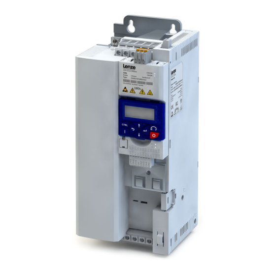
Hardware overview of the inverter PE connec on X100 Mains connec on/DC bus Relay output Network status LEDs X2xx Network Interface Diagnos c module Memory module Control terminals IT-screws Safety module X105 PTC input Motor connec on X109 Operating Instructions i550-Cabinet… -
Page 3: Table Of Contents
5.6 1-phase mains connection 120 V …………….11 5.7 1-phase mains connection 230/240 V ……………12 5.8 3-phase mains connection 230/240 V ……………13 5.9 3-phase mains connection 400 V …………….14 5.10 3-phase mains connection 480 V …………….16 6 Initial switch-on ………………….18 Operating Instructions i550-Cabinet…
-
Page 4: General Information
The product is designed for the installation into electrical systems or machinery. The i500 product family is designed for the power range of 0.25 … 132 kW. The inverter i550 is suitable for conveyor and travelling drives, pumps, fans, winders, lifting systems and many other machine tasks.
-
Page 5: Identification Of The Products
Design types Standard I/O without network 000S The product may cause EMC interferences. The operator is responsible for executing the (examples) Application I/O without network 001S interference suppression measures. Operating Instructions i550-Cabinet…
-
Page 6: Layout Of Warning Notices
In the event of a short circuit of two power transistors, a residual movement of up to 180°/ number of pole pairs on the motor may occur (e.g. 4-pole motor): residual movement max. 180 °/2 = 90°). Operating Instructions i550-Cabinet…
-
Page 7: Standards And Operating Conditions
200 % for 3 s; 150 % for 60 s (120-V network and 230-V network) TX10 Overload capacity 200 % for 3 s; Heavy Duty: 150 % for 60 s; (400-V network) Light Duty: 125 % for 60 s TX10 Operating Instructions i550-Cabinet…
-
Page 8: Mechanical Installation
75 … 90 Device width (Y not visible in the illustration) I55AExxxF 110 … 132 35.6 Device depth X — X: Hole spacing over center of device Hole dimension for top/bottom fixing Top mounting clearance Bottom mounting clearance Operating Instructions i550-Cabinet…
-
Page 9: Electrical Installation
< 150/300 pF/m ≥ 4 mm²) Control terminals +24 V +10 V 100 mA Alternatively, the motor cable can be shielded on an optional motor shield plate. » » » DC 24 V SELV/PELV (+19.2 … +28.8 V) Operating Instructions i550-Cabinet…
-
Page 10: Control Terminals
Inverter [kW] 0.25 … 132 Connection PTC or thermal contact Front X109 Terminal X109: T1 Back Terminal X109: T2 Sensor types PTC single sensor PTC triplet sensor Thermal contact DC 24 V SELV/PELV (+19.2 … +28.8 V) Operating Instructions i550-Cabinet…
-
Page 11: 1-Phase Mains Connection 120 V
Max. output current (15 s) Operation without mains choke Rated mains current 16.8 22.9 Fuse Characteristic gG/gL or gRL Motor connection Max. rated current Circuit breaker Characteristic Max. rated current Earth-leakage circuit breaker 1-phase mains connection ≥ 30 mA, type B Operating Instructions i550-Cabinet…
-
Page 12: 1-Phase Mains Connection 230/240 V
AC 208 V … 240 V Circuit breaker Characteristic … 2/PE Max. rated current AC 170 V … 264 V Earth-leakage circuit breaker 45 Hz … 65 Hz 1-phase mains connection ≥ 30 mA, type B Motor connection Operating Instructions i550-Cabinet…
-
Page 13: 3-Phase Mains Connection 230/240 V
Operation without mains choke Rated mains current 13.6 20.6 28.8 Fuse Characteristic gG/gL or gRL Max. rated current Circuit breaker Characteristic Max. rated current Earth-leakage circuit breaker 3-phase mains connection ≥ 30 mA, type B ≥ 300 mA, type B Operating Instructions i550-Cabinet…
-
Page 14: 3-Phase Mains Connection 400 V
Max. rated current Earth-leakage circuit breaker 3-phase mains connection ≥ 30 mA, type B ≥ 300 mA, type B In case of Light Duty above 15 kW and Heavy Duty above 22 kW, a mains choke must be used. Operating Instructions i550-Cabinet…
-
Page 15
Circuit breaker Characteristic Max. rated current Earth-leakage circuit breaker 3-phase mains connection ≥ 300 mA, type B In case of Light Duty above 15 kW and Heavy Duty above 22 kW, a mains choke must be used. Operating Instructions i550-Cabinet… -
Page 16: 3-Phase Mains Connection 480 V
Max. rated current Earth-leakage circuit breaker 3-phase mains connection ≥ 30 mA, type B ≥ 300 mA, type B In case of Light Duty above 15 kW and Heavy Duty above 30 kW, a mains choke must be used. Operating Instructions i550-Cabinet…
-
Page 17
Circuit breaker Characteristic Max. rated current Earth-leakage circuit breaker 3-phase mains connection ≥ 300 mA, type B In case of Light Duty above 15 kW and Heavy Duty above 30 kW, a mains choke must be used. Operating Instructions i550-Cabinet… -
Page 18: Commissioning
• The analog input X3/AI1 must not be wired or connected to GND. Switch on mains voltage ► Switch on mains voltage and check readiness for operation. Observe LED status displays “RDY” and “ERR” on the inverter front panel. See „LED status“. Operating Instructions i550-Cabinet…
-
Page 19: Functions Of The Keys
3 s. P211.00 7.1.2 Example of the keypad handling Example for DO1 function assignment with parameter P420.02. P430.03 I/O setting GROUP 4 P430.02 P430.02 P210.00 Fct. dig. outputs P420.XX Time DO1 func on P420.02 Operating Instructions i550-Cabinet…
-
Page 20: Extended Terminal Control
A USB module and a standard USB cable (A plug to micro-B plug) is required for this. *P420.02 Release brake GND for analog and digital signals http://www.Lenze.com Relay activated at Relay NO contact *P420.01 Ready for operation Relay common contact Relay NC contact Operating Instructions i550-Cabinet…
-
Page 21: The Most Important Parameters At A Glance
Commissioning The most important parameters at a glance This chapter contains the most important parameters and selections. You can find a detailed description in the commissioning document. http://www.Lenze.com The parameters are divided into the following function groups: • Pxxx.xx group 0: Favorites •…
-
Page 22
V/f characteristic control The control mode is used for speed control of an asynchronous motor via a V/f characteristic with speed feedback. (VFC closed loop) This motor control mode is described in the commissioning manual. http://www.Lenze.com P302.00 V/f characteristic Linear Linear characteristic for drives with constant load torque over the speed. -
Page 23
Reverse rot. dir. Digital input 3 [13] Assignment of a trigger to the “Reverse rotating direction” function. Trigger = TRUE: The setpoint specified is inverted (i.e. the sign is inverted). Trigger = FALSE: No action / deactivate function again. Operating Instructions i550-Cabinet… -
Page 24
• The standard setpoint source for operating mode is selected in P201.01. P440.01 AO1 output area Inhibited Definition of the output range. 0 … 10 V DC 0 … 5 V DC 2 … 10 V DC 4 … 20 mA 0 … 20 mA Operating Instructions i550-Cabinet… -
Page 25
Parameterizable frequency setpoints (preset 2). P450.03 Freq. preset 3 0.0 … 50.0 – 40.0 … 599.0 Hz Parameterizable frequency setpoints (preset 3). P450.04 Freq. preset 4 0.0 … 0.0 … 599.0 Hz Parameterizable frequency setpoints (preset 4). * Default setting dependent on the model Operating Instructions i550-Cabinet… -
Page 26: Group 2: Basic Setting
In progress • When the inverter is switched on, all parameters are automatically loaded from the user memory of the memory module to the RAM Action cancelled memory of the inverter. No access No access (Inverter disabled) Operating Instructions i550-Cabinet…
-
Page 27: Troubleshooting
2. Via P400.04 (default setting of digital input 2). • Cause of error has been eliminated and no blocking time is active. • The error is reset if a signal is applied to digital input 2 (P400.04). Operating Instructions i550-Cabinet…
-
Page 28: Error Codes
• Clean fan and ventilation slots. If required, replace fan. The fans can be unlocked via locking hooks and can then be removed. Error: Motor overtemperature Fault • Check drive sizing. 4310 • Check motor temperature sensor and wiring (X109/T1 and X109/T2). Operating Instructions i550-Cabinet…
-
Page 29
Note: The warning will be reset if the thermal load falls below the warning threshold (P707.08) of — 20 %. Automatic start disabled Fault • Deactivate start command and reset error. FF37 FF85 Keypad full control active Warning • To exit the control mode, press the keypad key. Operating Instructions i550-Cabinet… -
Page 30: Led Status
Fundamental information on project planning and ordering the product Commissioning document Fundamental information for the installation and commissioning of the product Mounting instructions Fundamental information on mounting the product The documents can be found in the Lenze Doc Finder. Operating Instructions i550-Cabinet…
-
Page 31
Further documents Operating Instructions i550-Cabinet… -
Page 32
© 01/2020 | 3.0 Lenze Drives GmbH Postfach 10 13 52, 31763 Hameln Breslauer Straße 3, 32699 Extertal GERMANY HR Lemgo B 6478 Phone: +49 5154 82-0 Fax: +49 5154 82-2800 E-mail: Sales.de@Lenze.com Web: www.Lenze.com Lenze Service GmbH Breslauer Straße 3, 32699 Extertal…
Table of Contents for Lenze i550:
-
7.7 Setpoint diagnoscs The following parameters show the current setpoints of dierent setpoint sources. Parameter Address Name / seng range / [default seng] Info 0x282B:007 Inverter diagnoscs: Default frequency setpoint • Read only: x.x Hz • From version 03.00 Display of the frequency setpoint of the standard setpoint source set in 0x2860:001 (P201.01). 0x282B:008 Inverter diagnoscs: Preset frequency setpoint • Read only:
-
Address Name / seng range / [default seng] Info 0x261C:050 (P740.50) Favorites sengs: Parameter 50 (Favorites se.: Parameter 50) 0x00000000 … [0x29110400] … 0xFFFFFF00 4.5 Saving the parameter sengs 4.5.1 Save parameter sengs with keypad If one parameter seng has been changed with the keypad but has not been saved in the memory module with mains failure protecon, the SET display is blinking. In order to save parameter sengs in the user memory of the memory module, press the key- pad enter key for more than 3 s. MAN MAN MANAUTO
-
12.12.2 Basic seng and opons 12.12.2.1 Node address seng Each network node must be provided with a unique node address. • The node address of the inverter can be oponally set in 0x2321:001 (P510.01) or using the DIP switches on the device labelled with «1» … «128». • The seng that is acve when the inverter is switched on is the eecve seng. • The labelling of the DIP switches corresponds to the values of the individual DIP switches for determining the node address (see the following example
-
8.2 Congure setpoint sources The standard setpoint source for torque control can be selected in 0x2860:003 (P201.03). This chapter describes the seng opons for the various setpoint sources. • Preset torque setpoint source: Analog input 1. Set the seng range in 0x2636:011 (P430.11) and 0x2636:012 (P430.12) in this selecon. • In case of selecon «Analog input 2 [3]»: Set seng range in 0x2637:011 (P431.11) and 0x2637:012 (P431.12). • Except for
-
Changing inverter sengs by means of the keypad (general operaon) AUTO SET REM 0 0 0 O 1 5 AUTO SETREM AUTO SETREM O P 4 O O x x AUTO SETREM AUTO SETREM O P 4 2 O x x AUTO SETREM O P 4 2 O O 1 AUTO SETREM O P 4 2 O O 2 1 AUTO SETREM VEL:FLEX:AIN1 0 0 0 S T O P G R O U P O O G R O U P O 4 2. Apply change Change to parameterisation mode Back to the operating mode Back Back Operating mode Release brake SUB parameter level DO1 functionRelay function Disca
-
Details The voltage threshold for braking operaon results on the basis of the rated mains voltage set: Rated mains voltage Voltage thresholds for braking operaon Braking operaon on Braking operaon o 230 V DC 390 V DC 380 V 400 V DC 725 V DC 710 V 480 V DC 780 V DC 765 V The voltage threshold for braking operaon can be reduced by 0 … 100 V. The reducon required must be set in 0x2541:003 (P706.03). However, the reducon must be made to such an extent that the reduced voltage threshold
-
Address Designaon Default seng Category Data type Factor A M 0x2637:012 (P431.12) Analog input 2: Max torque value 100.0 % general I16 10 P — 0x2639:001 (P440.01) Analog output 1: Output range 0 … 10 VDC [1] general U8 1 P — 0x2639:002 (P440.02) Analog output 1: Funcon Output frequency [1] general U8 1 P — 0x2639:003 (P440.03) Analog output 1: Min. signal 0 general I32 1 P — 0x2639:004 (P440.04) Analog output 1: Max. sign
-
Address Designaon Default seng Category Data type Factor A M 0x400B:001 (P592.01) Process input data: AC Drive control word 0x0000 general U16 1 OH K r 0x400B:002 (P592.02) Process input data: LECOM control word 0x0000 general U16 1 OH K r 0x400B:003 (P592.03) Process input data: Network setpoint frequency (0.1) 0.0 Hz general U16 10 OK r 0x400B:004 (P592.04) Process input data: Network setpoint speed 0 rpm general U16 1 OK r 0x400B:005 (P592.05) Process input data: Network setpoint fr
-
12.12.5 Diagnoscs 12.12.5.1 LED status display Informaon on the Modbus status can be obtained quickly via the «COMM» and «ERR» LED displays on the front of the inverter. The meaning can be seen from the tables below. Inverter not acve on the Modbus bus (yet) LED «COMM» LED «ERR» Meaning o on Internal error Both LEDs are ickering alternately Automac detecon of baud rate and data format acve. Inverter acve on the Modbus The green «COMM&qu
-
10.4.3 Dene V/f characterisc shape Various characterisc shapes are available which are described in detail in the following sub- chapters. Parameter Address Name / seng range / [default seng] Info 0x2B00 (P302.00) V/f characterisc shape (V/f charac.shape) • Seng can only be changed if the inverter is inhibi- ted. Selecon of the V/f characterisc shape for the adaptaon to dierent load proles. 0 Linear Linear characterisc for drives with constant load torque over the speed. 4Linear V/f characterisc ^ 178 1 Quadrac Squ
-
10.7.1 Automac motor idencaon (energized) The automac idencaon of the motor results in the best possible parameter sengs. If the applicaon enables you to energise the system during the opmisaon, carry out this opmisaon. Precondions The motor must be cold. • All rated motor data is known and set in the inverter, either by selecng the motor from the motor catalogue or manually. 4Select motor
-
12.15.4.3 Error codes The following table lists all possible error codes for the acyclic data exchange: Error code Descripon Explanaon Addional infor- maon 0x0000 Parameter number impermissible Access to non-available parameter. — 0x0001 Parameter value cannot be changed Change access to a parameter value that cannot be changed. Subindex 0x0002 Lower or upper value limit exceeded Change access with value beyond the value limits. Subindex 0
Questions, Opinions and Exploitation Impressions:
You can ask a question, express your opinion or share our experience of Lenze i550 device using right now.
-
Contents
-
Table of Contents
-
Troubleshooting
-
Bookmarks
Quick Links
Operating instructions i550 motec frequency inverter | 1
Operating instructions
i550 motec frequency inverter
0.37 … 5.5 kW
Contents
© 03/2022 · EN · www.Lenze.com
Related Manuals for Lenze i550 Series
Summary of Contents for Lenze i550 Series
-
Page 1
Operating instructions i550 motec frequency inverter | 1 Operating instructions i550 motec frequency inverter 0.37 … 5.5 kW Contents © 03/2022 · EN · www.Lenze.com… -
Page 2: General Information
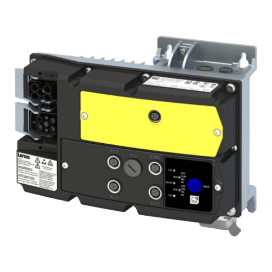
Han Q4/2 female (Daisy Chain) Fan, option Warnings Status LEDs X3.1 Control connections X105 Motor connection X3.2 Control connections Diagnostic interface Han Q8 M23 power Network (OUT) X397 X396 Network (IN) © 03/2022 · EN · www.Lenze.com…
-
Page 3
The complete documentation, further • The cables must be installed in accordance with EN IEC 60204-1 or US National Electrical information and tools regarding Lenze products can be found on the Internet: Code NFPA 70/Canadian Electrical Code C22.1. -
Page 4: Identification Of The Products
With repair switch with protective func- Motor adapter for BG160 — BG180 tion, monitored, control element, and potentiometer Application area Default parameter setting: Region EU (50- Hz networks) Default parameter setting: Region US (60- Hz networks) © 03/2022 · EN · www.Lenze.com…
-
Page 5
Indicates an extremely hazardous situation. If this instruction is ignored, serious, irreversible injury or deadly injuries may result. NOTE Indicates a material hazard. If this instruction is ignored, damage to property may result. © 03/2022 · EN · www.Lenze.com… -
Page 6: Safety Instructions
— They are familiar with installing, mounting, commissioning, and operating the product. — They have the corresponding qualifications for their work. — They know and can apply all regulations for the prevention of accidents, directives, and laws applicable at the place of use. © 03/2022 · EN · www.Lenze.com…
-
Page 7
In the event of a short circuit of two power transistors, a residual movement of up to 180°/ number of pole pairs on the motor may occur (e.g. 4-pole motor): Residual movement max. 180 °/2 = 90°). © 03/2022 · EN · www.Lenze.com… -
Page 8: Technical Data
Device-specific; see technical data in project planning document Max. output frequency 0 Hz … 599 Hz Overload capacity 200 % for 3s, 150 % for 60s Further standards and operating conditions can be found in the project planning documents. © 03/2022 · EN · www.Lenze.com…
-
Page 9: Mechanical Installation
I55AMxxxC 1.5 … 3 kW 4x M5 >50 3-phase mains connection 400/480 V devices I55AMxxxF 0.37 … 2.2 kW 4x M5 >50 I55AMxxxF 3 … 5.5 kW 4x M5 >50 © 03/2022 · EN · www.Lenze.com…
-
Page 10: Electrical Installation
• Device screws must be tightened to the specified tightening torque. NOTE For voltage supply with DC 24 … 48 V (-20 % … +4 %), use only a safely separated power supply unit in accordance with prevailing SELV/PELV requirements. © 03/2022 · EN · www.Lenze.com…
-
Page 11: Connection Diagram
Several inverters in close proximity can be connected to the mains using the integrated n.c. Han-Q4/2 connectors. The mains cables are looped through from one inverter to the next via X3.2 the Han-Q4/2 connector. 24V| L+(2) GND| L-(2) DI3| DO2|C/Q(2) n.c. » » © 03/2022 · EN · www.Lenze.com…
-
Page 12
Max. rated current Max. short-circuit current (SCCR) Circuit breaker Characteristic Max. rated current Max. short-circuit current (SCCR) Residual current device (RCD) ≥ 30 mA, type B * Overload time = 3 s, recovery time = 12 s © 03/2022 · EN · www.Lenze.com… -
Page 13
Max. rated current Max. short-circuit current (SCCR) Circuit breaker Characteristic Max. rated current Max. short-circuit current (SCCR) Residual current device (RCD) ≥ 30 mA, type B * Overload time = 3 s, recovery time = 12 s © 03/2022 · EN · www.Lenze.com… -
Page 14
Max. rated current Max. short-circuit current (SCCR) Circuit breaker Characteristic Max. rated current Max. short-circuit current (SCCR) Residual current device (RCD) ≥ 30 mA, type B * Overload time = 3 s, recovery time = 12 s © 03/2022 · EN · www.Lenze.com… -
Page 15: Control Connections
M12 (A coded) X3.1 X3.2 24 V 24 V Not assigned Housing is connected to functional earth Further configuration options for the connectors can be found in the commissioning document. © 03/2022 · EN · www.Lenze.com…
-
Page 16: Ptc Input
M12 connectors as well as to the auxiliary supply to not restrict the safe isolation of the M12 connectors. © 03/2022 · EN · www.Lenze.com…
-
Page 17
• Modbus TCP • PROFINET The Ethernet interface is designed as an M12 connector: X396 (IN) / X397 (OUT) M12 (D coded) Assignment Housing is connected to functional earth © 03/2022 · EN · www.Lenze.com… -
Page 18: Functional Safety
• For safety-related braking functions, use safety-rated brakes only. • The user must ensure that the inverter is only operated within the specified environmental conditions in its intended application. Only by doing so can the specified safety-related characteristics be adhered to. © 03/2022 · EN · www.Lenze.com…
-
Page 19
S2: Safety switching device Switch-off time Safety-related characteristic values and further example circuits can be found in the project Input current SIA planning document. Input current SIB Input peak current Test pulse duration Test pulse interval © 03/2022 · EN · www.Lenze.com… -
Page 20: Initial Switch-On
• The control connections of the safety technology must be wired. 1. Switch on mains voltage. 2. Check readiness for operation. 3. Observe the «DRIVE» LED status display on the front of the inverter. © 03/2022 · EN · www.Lenze.com…
-
Page 21: Important Notes
• Parameterizing without motor operation does not require a mains voltage. If you connect the inverter directly to the PC without a hub, the USB interface of the PC is sufficient for the voltage supply. © 03/2022 · EN · www.Lenze.com…
-
Page 22
»EASY Starter« searches for connected devices via the communication path selected. When the connection has been established successfully, the inverter is displayed in the device list of »EASY Starter«. The inverter parameters can now be accessed via the tabs of »EASY Starter«. © 03/2022 · EN · www.Lenze.com… -
Page 23: Quick Commissioning
Start drive: • Drive enabled: X1/SIA = HIGH and X1/SIB = HIGH • Start drive: X3.1/DI1 = HIGH — The drive rotates with setpoint frequency preset 1 (0x2911:001) Stop drive again: X3.1/DI1 = LOW © 03/2022 · EN · www.Lenze.com…
-
Page 24: Parameter List
Group 0 — favorites Group 0 contains the configurable favorites that are also contained in the groups 1 to 4. In the default setting these are the most common parameters for the solution of typical applications. © 03/2022 · EN · www.Lenze.com…
-
Page 25
• The V/f base voltage is usually set to the rated motor voltage. • The V/f base frequency is usually set to the rated motor frequency. 0x2B01:002 Base frequency 0 … 50 … 1500 Hz * Default setting dependent on the model © 03/2022 · EN · www.Lenze.com… -
Page 26
Start reverse Not connected Trigger = TRUE > FALSE (edge): No action. To stop the motor, set function «Start» to FALSE (0x2631:002, default digital input 1). * Default setting dependent on the model © 03/2022 · EN · www.Lenze.com… -
Page 27
Parameterizable frequency setpoints Setpoint frequency 0x2911:003 0.0 … 50.0 … 599.0 Hz presets: Preset value 3 Setpoint frequency 0x2911:004 0.0 … 0.0 … 599.0 Hz presets: Preset value 4 * Default setting dependent on the model © 03/2022 · EN · www.Lenze.com… -
Page 28
(0x2916) to standstill. In the case of a lower actual frequency, the actual deceleration time is reduced accordingly. • Setting is not effective in the operating mode 0x6060 = “CiA: Velocity mode [2]”. © 03/2022 · EN · www.Lenze.com… -
Page 29: Group 3 — Motor Control
Motor parameter: Rated voltage 0 … 230 … 65535 V Only enter the data applying to the connection type selected. 0x2C01:008 Motor parameter: Cosine phi 0.00 … 0.80 … 1.00 © 03/2022 · EN · www.Lenze.com…
-
Page 30
On / start successfully, the value 0 is shown. 0x2022:002 Device commands: Save user data • Do not switch off the supply voltage during the saving process! Off/ready Only status feedback © 03/2022 · EN · www.Lenze.com… -
Page 31: Troubleshooting
2. Via error reset signal (0x2631:004, default digital input 2). • Prerequisite: Cause of error has been eliminated and no blocking time is active. • The error is reset if a signal is applied to digital input 2. © 03/2022 · EN · www.Lenze.com…
-
Page 32: Error Codes
• Check optional external auxiliary supply on X100.1/24E.1, if connected. 5112 24 V supply critical Warning • Check mains voltage. 5180 24 V supply overload Warning • Check 24 V output and digital outputs for earth fault or overload. © 03/2022 · EN · www.Lenze.com…
-
Page 33
Motor overspeed Error • Adapt the maximum motor speed (0x6080) and the error threshold (0x2D44:001). FF37 Automatic start disabled Error • Deactivate start command and reset error. © 03/2022 · EN · www.Lenze.com… -
Page 34
Inverter enabled, warning active. The motor rotates according to the specified setpoint or blinking fast quick stop active. Inverter enabled, quick stop active as response to a fault. blinking © 03/2022 · EN · www.Lenze.com… -
Page 35
LED status Support Support Further information can be found on the online page www.lenze.com/product-information The material number of the product can be found on the nameplate. © 03/2022 · EN · www.Lenze.com… -
Page 36
More detailed information on disposal can be obtained from the corresponding specialist firms and the competent authorities. The packaging of the component must be disposed of separately. Paper, cardboard and plastics must be recycled. © 03/2022 · EN · www.Lenze.com…