- Manuals
- Brands
- GE Manuals
- Medical Equipment
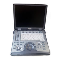
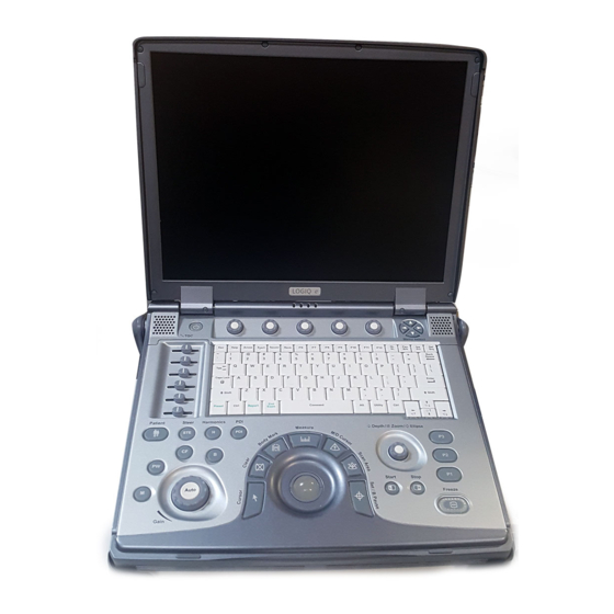
- LOGIQ e
Manuals and User Guides for GE LOGIQ e. We have 3 GE LOGIQ e manuals available for free PDF download: Basic Service Manual, Technical Publication, Quick Manual
GE LOGIQ e Basic Service Manual (427 pages)
Brand: GE
|
Category: Medical Equipment
|
Size: 43.4 MB
Table of Contents
-
Certified Electrical Contractor Statement — for USA Only
13
-
Damage in Transportation
13
-
Omission and Errors
14
-
Service Safety Considerations
15
-
Copyrights
16
-
Legal Notes
16
-
Proprietary to GE
16
-
Trademarks
16
-
Table of Contents
17
-
Chapter 1 — Introduction
25
-
Overview
26
-
Contents in this Chapter
26
-
-
Manual Overview
27
-
Contents in this Section
27
-
Contents in this Service Manual
27
-
Typical Users of the Basic Service Manual
28
-
LOGIQ E Models Covered by this Manual
29
-
General Caution
30
-
-
Important Conventions
31
-
Conventions Used in Book
31
-
Standard Hazard Icons
33
-
-
Product Icons
35
-
Label Icon Description
35
-
Introduction
36
-
Contents in this Section
43
-
Human Safety
43
-
Mechanical Safety
46
-
Electrical Safety
48
-
Battery Safety
50
-
-
Dangerous Procedure Warnings
52
-
Lockout/Tagout (LOTO) Requirements
53
-
Returning Probes and Repair Parts
54
-
EMC, EMI and ESD
55
-
Contents in this Section
55
-
What Is EMC
55
-
CE Compliance
55
-
Electrostatic Discharge (ESD) Prevention
56
-
-
Customer Assistance
57
-
Contact Information
57
-
Phone Numbers for Customer Assistance
58
-
System Manufacturer
58
-
Factory Site
59
-
-
-
Chapter 2 — Site Preparations
61
-
Overview
62
-
Contents in this Chapter
62
-
-
General Requirements
63
-
Contents in this Section
63
-
Ultrasound System Environmental Requirements
63
-
Electrical Requirements
66
-
EMI Limitations
69
-
Probes Environmental Requirements
71
-
-
Facility Needs
72
-
Purchaser Responsibilities
72
-
Required Facility Needs
73
-
Desirable Features
74
-
Suggested and Alternate Ultrasound Room Layout
75
-
Networking Setup Requirements
76
-
-
Environmental Dangers
79
-
Patient Environment IEC60601-1And ANSI AAMI ES60601-1
79
-
-
-
Chapter 3 — System Setup
81
-
Overview
82
-
Contents in this Chapter
82
-
-
Setup Reminders
83
-
Contents in this Section
83
-
Average Setup Time
83
-
Setup Warnings
83
-
-
Receiving and Unpacking the Equipment
86
-
Contents in this Section
86
-
Receiving the LOGIQ E
86
-
Unpacking the LOGIQ E
87
-
Packing the Equipment
90
-
-
Preparing for Setup
91
-
Verify Customer Order
91
-
Physical Inspection
91
-
EMI Protection
91
-
-
Completing the Setup
92
-
Contents in this Section
92
-
System Specifications
92
-
Electrical Specifications
93
-
Power on / Boot up
94
-
Power Off/Shutdown
96
-
Connecting Probes
97
-
-
System Configuration
99
-
Contents in this Section
99
-
LOGIQ E Configuration
100
-
Connecting Cables
102
-
Peripheral/Accessories Connector Panel
103
-
Available Probes
110
-
Software Options Configuration
111
-
Connectivity Setup
111
-
-
Paperwork after Setup
113
-
User’s Manual(S)
113
-
Product Locator Installation Card
113
-
-
Peripherals Installation
114
-
Contents in this Section
114
-
Overview
115
-
Furnished Materials
116
-
Peripherals Installation Instructions
118
-
-
-
Chapter 4 — General Procedures and Functional Checks
135
-
Overview
136
-
Contents in this Chapter
136
-
Special Equipment Required
136
-
-
General Procedures
137
-
Contents in this Section
137
-
Caution and Warning
138
-
Power On/Boot up
139
-
Power Shut down
145
-
Removable Media
147
-
Archiving and Loading Presets
147
-
Where Are the User Manuals and the Service Manual
148
-
How to Display or Print the PDF Files from the Manual CD-ROM
149
-
Lockout/Tagout (LOTO) Requirements
150
-
-
Functional Checks
151
-
Contents in this Section
151
-
Overview
152
-
Operator Panel
152
-
Soft Menu Key Tour
153
-
Monitor Display
154
-
Performance Tests
155
-
Software Configuration Checks
186
-
Peripheral Checks
186
-
-
-
Chapter 5 — Components and Functions (Theory)
195
-
Overview
196
-
Contents in this Chapter
196
-
-
Block Diagram and Theory
197
-
Contents in this Section
197
-
Block Diagram
197
-
General Information
198
-
Top Console
198
-
Overview
199
-
AC Power
199
-
Battery Charging
200
-
Air Flow Distribution
200
-
-
Common Service Platform
201
-
Contents in this Chapter
201
-
Introduction
201
-
The Usage for Security Cable
202
-
Global Service User Interface (GSUI)
203
-
Service Login
203
-
Access/Security
204
-
Customer Service Home Page
207
-
-
-
Chapter 6 — Service Adjustments
209
-
LCD Monitor Adjustments
210
-
Purpose of this Section
210
-
Monitor Adjustments
210
-
-
-
Chapter 7 — Diagnostics/Troubleshooting
211
-
Overview
212
-
Contents in this Chapter
212
-
-
Gathering Trouble Data
213
-
Overview
213
-
Contents in this Section
213
-
Collect Vital System Information
213
-
Collect a Trouble Image with Logs
215
-
-
USB Quick Save
217
-
Overview
217
-
Check and Record the P3 Key Function
217
-
Setting the P3 Key to USB Quick Save
218
-
-
Screen Capture
219
-
Contents in this Section
219
-
Check and Record the P1 Key Function
220
-
Setting the P1 Key to Screen Capture
220
-
Capturing a Screen
221
-
Reset the P1 Key to Customer’s Functionality
222
-
-
Global Service User Interface (GSUI)
223
-
Contents in this Section
223
-
Common Diagnostics
223
-
-
Network Configuration
227
-
Contents in this Section
227
-
Software Download
230
-
-
-
Chapter 8 — Replacement Procedures
237
-
Overview
238
-
Contents in this Chapter
238
-
-
Warnings and Important Information
239
-
Warnings
239
-
Returning/Shipping Probes and Repair Parts
240
-
-
Disassembly/Re-Assembly
241
-
Warning and Caution
241
-
Handle Assy (Part No. 5483188)
242
-
-
Loading the Software
249
-
Contents in this Section
249
-
Purpose of this Section
249
-
Customer Provided Prerequisite
249
-
Data Management — Moving All Images
250
-
Backing up the Patient Archive and System Configurations
250
-
Recording Important Settings and Parameters
251
-
Loading the System Software
252
-
-
-
Chapter 9 — Renewal Parts
263
-
Overview
264
-
Contents in this Chapter
264
-
List of Abbreviations
264
-
-
Renewal Parts Lists
265
-
Contents in this Section
265
-
Power Cable
266
-
Operator Console Assy
267
-
LCD Assy
268
-
Keyboard Assy
269
-
Bottom Assy
271
-
E-Isolation Cart and Advanced Isolation Cart
275
-
Accessories and Kits
279
-
Probe
281
-
Manuals
283
-
-
-
Chapter 10 — Care and Maintenance
285
-
Overview
286
-
Contents in this Chapter
286
-
-
Protecting Health Information
287
-
Hide Patient Data
287
-
Users
289
-
Logon
291
-
-
Warnings
292
-
Why Do Maintenance
293
-
Periodic Maintenance Inspections
293
-
Keeping Records
293
-
Quality Assurance
294
-
-
Maintenance Task Schedule
295
-
How Often Should Maintenance Tasks be Performed
295
-
-
Tools Required
297
-
Standard GE Tool Kit
297
-
GE-2 Tool Kit
299
-
Special Tools, Supplies and Equipment Used for Maintenance
300
-
-
System Maintenance
301
-
Contents in this Section
301
-
Preliminary Checks
301
-
Functional Checks
303
-
Physical Inspection
305
-
Optional Diagnostic Checks
306
-
Probe Maintenance
307
-
Battery Performance Maintenance
309
-
-
Electrical Safety Tests
310
-
Safety Test Overview
310
-
Leakage Current Limits
313
-
Outlet Test — Wiring Arrangement
315
-
Grounding Continuity
316
-
Chassis Leakage Current Test
317
-
Probe Leakage Current Test
319
-
-
When There’s too Much Leakage Current
322
-
AC/DC Fails
322
-
Chassis Fails
322
-
Probe Fails
323
-
Peripheral Fails
323
-
Still Fails
323
-
New Unit
323
-
ECG Fails
323
-
-
Inspection Paperwork
324
-
Ultrasound Inspection Forms
324
-
-
Electrical Safety Tests Log
326
-
-
Chapter 11 — Docking Cart Setup
329
-
Overview
330
-
Contents in this Chapter
330
-
-
Set up Docking Cart
332
-
Contents in this Section
332
-
Setup Reminders
333
-
Receiving and Unpacking the Equipment
336
-
Preparing for Installation
340
-
Peripheral Installation
342
-
Options Installation
353
-
Paperwork
367
-
-
Cart Using
368
-
Contents in this Section
368
-
Introduction
368
-
Height Adjustment
368
-
Locking the Wheels
369
-
Mounting the System to Cart
369
-
Release the System from Docking Cart
370
-
Switch the Three Probes
371
-
System Operation
371
-
-
Docking Cart Functions (Theory)
372
-
Information
373
-
Supported External Interface/Port
373
-
Configuration on External Display through DVI Connection
374
-
-
Diagnostics/Troubleshooting
380
-
Overview
380
-
Troubleshooting
380
-
Gathering Trouble Data
380
-
Troubleshooting Trees
381
-
-
-
Chapter 12 — Docking Cart Servicing
385
-
Replacement Procedure
386
-
Introduction
386
-
Disassembly/Re-Assembly
386
-
-
Renewal Parts
386
-
Contents in this Section
387
-
Introduction
387
-
Power Cable
397
-
Operator Console Assy
398
-
Docking Station
399
-
Probe Holder
401
-
Shelf Service
403
-
Bottom and Wheels
404
-
Panel and Cabinet
405
-
Gas Spring and Gas Spring Lever
405
-
Power Box and Extended Life Battery
405
-
-
Overview
386
-
Contents in this Chapter
386
-
List of Abbreviations
386
-
-
Care & Maintenance
407
-
Contents in this Section
407
-
Overview
407
-
Why Do Maintenance
409
-
Maintenance Task Schedule
410
-
Tools Required
412
-
Cleaning Dusk Screen
413
-
Safety Test (Continued)
414
-
When There’s too Much Leakage Current
418
-
-
Advertisement
GE LOGIQ e Technical Publication (127 pages)
Ultrasound System
Brand: GE
|
Category: Medical Equipment
|
Size: 3.71 MB
Table of Contents
-
Table of Contents
21
-
Chapter 1 — Overview
25
-
Content in this Manual
26
-
Product Description
27
-
Overview of the Ultrasound System
27
-
-
Products Covered in this Manual
28
-
-
Chapter 2 — Safety Information
29
-
Overview
30
-
Contents in this Chapter
30
-
-
Important Conventions
31
-
Conventions Used in Book
31
-
Standard Hazard Icons
33
-
-
Product Icons
35
-
Label Icon Description
35
-
How to Lock the Operator Panel Prior to Transport
35
-
-
Safety Considerations
36
-
Introduction
36
-
Human Safety
36
-
Mechanical Safety
39
-
Electrical Safety
44
-
-
Label Locations
46
-
Product Labels
46
-
-
Dangerous Procedure Warnings
47
-
Warnings
47
-
-
Lockout/Tagout (LOTO)
48
-
LOTO Requirements
48
-
-
Returning Probes and Repair Parts
49
-
Requirements for Returning Parts
49
-
User Responsibility
49
-
-
Electromagnetic Compatibility (EMC)
50
-
What Is EMC
50
-
Compliance
50
-
Electrostatic Discharge (ESD) Prevention
51
-
-
-
Chapter 3 — Site Preparations
53
-
Overview
54
-
Contents in this Chapter
54
-
-
General Ultrasound System Requirements
55
-
Contents in this Section
55
-
Ultrasound System Environmental Requirements
55
-
Electrical Requirements
57
-
EMI Limitations
70
-
Probes Environmental Requirements
72
-
Time and Manpower Requirements
72
-
-
Facility Needs
73
-
Contents in this Section
73
-
Purchaser Responsibilities
73
-
Required Facility Needs
75
-
Desirable Features
77
-
Care and Maintenance
79
-
Contents in this Chapter
80
-
-
-
Chapter 4 — Care and Maintenance
81
-
Warnings
81
-
Why Do Maintenance
82
-
Keeping Records
82
-
Quality Assurance
82
-
-
Maintenance Task Schedule
83
-
How Often Should Maintenance Tasks be Performed
83
-
-
System Maintenance
84
-
Preliminary Checks
84
-
Functional Checks
85
-
Physical Inspection
87
-
Cleaning
89
-
Probe Maintenance
90
-
-
Using a Phantom
91
-
Phantoms
91
-
-
Electrical Safety Tests
92
-
Content in this Section
92
-
Uninterrupted Power Supply (UPS)
93
-
Safety Test Overview
94
-
Leakage Current Limits
97
-
Outlet Test — Wiring Arrangement — USA and Canada
101
-
Grounding Continuity
102
-
Chassis Leakage Current Test
103
-
Isolated Patient Lead (Source) Leakage-Lead to Ground
107
-
Isolated Patient Lead (Source) Leakage-Lead to Lead
109
-
Isolated Patient Lead (Sink) Leakage-Isolation Test
111
-
Probe (Source) Leakage Current Test
113
-
Isolated Probe (Sink) Leakage-Isolation Test
118
-
-
When There’s too Much Leakage Current
122
-
AC/DC Fails
122
-
Chassis Fails
122
-
Probe Fails
123
-
Peripheral Fails
123
-
Still Fails
123
-
New Ultrasound System
123
-
ECG Fails
123
-
-
Ultrasound Equipment Quality Check (EQC and IQC)
124
-
Quality Checks
124
-
-

GE LOGIQ e Quick Manual (26 pages)
Brand: GE
|
Category: Medical Equipment
|
Size: 2.07 MB
Table of Contents
-
System Power
5
-
Starting an Exam
7
-
B/M Mode Image Optimize
8
-
B Mode Control Panel Controls
8
-
B/M Mode Scanning Hints
9
-
Scanning Hints
10
-
Basic Measurements
12
-
Using Probes
14
-
Probe Features
16
-
Specifications
16
-
Probe Cleaning and Disinfection Instructions
17
-
Probe Safety
17
-
Image Management
19
-
Configuring Connectivity
20
-
Using CINE
23
Advertisement
Advertisement
Related Products
-
GE LOGIQ e Vet
-
GE LOGIQ E8
-
GE LOGIQ 200 PRO Series
-
GE LOGIQ 9
-
GE LOGIQ 7
-
GE LOGIQ Book XP
-
GE LOGIQ P5 Premium OB
-
GE LOGIQ V5 Expert
-
GE LOGIQ C Series
-
GE LOGIQ 7 Pro
GE Categories
![]()
Refrigerator
Ranges
![]()
Microwave Oven
![]()
Air Conditioner
![]()
Dishwasher
More GE Manuals
- Manuals
- Brands
- GE Manuals
- Medical Equipment
- LOGIQ e
- Quick manual
-
Contents
-
Table of Contents
-
Bookmarks
Quick Links
RikshospitaletHF
Hurtigveiledning
Ultralydskanner
Figure 1. Steg 1
Steg 1 SKRU PÅ MASKINEN.
Kom igang
Related Manuals for GE LOGIQ e
Summary of Contents for GE LOGIQ e
-
Page 1
RikshospitaletHF Hurtigveiledning Ultralydskanner Figure 1. Steg 1 Steg 1 SKRU PÅ MASKINEN. Kom igang… -
Page 2
LOGIQ e Quick Guide LOGIQ e Knotologi 1. TGC. Juster venstre/høyre for justernig TGC. 2. Ny pasient. Trykk for aktivering. 3. Additional Feature Keys: Steer, Harmonics, PDI. 4. Mode/Gain/Auto Keys: M Mode, Pulsed Wave Doppler (PW) Modes, Color Flow (CF) Mode and B Mode. -
Page 3
LOGIQ e Quick Guide Direction 5130174-100 Rev. 2 LOGIQ e Keys SoftMenu Key Tour Function Keys — Programmable Keys Choices for program Keys In general, there are two types of softMenu keys: • F1 = Help (Enter Online Help / User Manual) •… -
Page 4
LOGIQ e Quick Guide Direction 5130174-100 Rev. 2 LOGIQ e Monitor Display Tour 1. Institution/Hospital Name, Date, Time, Operator 7. Cine Gauge. 16. Body Pattern. Identification, system status (real-time of 8. Measurement Summary Window. 17. Depth Scale. frozen). 9. Image. -
Page 5: System Power
LED is orange. Colors: Green and 220-240 VAC 220-240 VAC 2.5A 2.5A orange. (Europe) (Israel) 4. The fourth LED does not work on the LOGIQ e. 100-120 VAC 220-240 VAC 2.5A 2.5A (Japan) (Australia) Table 1: Example Plug and Outlet Configurations Figure 8.
-
Page 6
LOGIQ e Quick Guide Direction 5130174-100 Rev. 2 Power Off Full Maintenance Reboot Click OK to continue the process. The auto full maintenance reboot process takes about 2 minutes, To power down the system: You can select Full Maintenance Reboot to fully and is completed when the system is shut down restart the system. -
Page 7: Starting An Exam
LOGIQ e Quick Guide Direction 5130174-100 Rev. 2 Starting an Exam New Patient Probe Selection Function Selection Window [2] New Patient is used to clear the patient entry To start a new patient’s exam, Select a probe from the Touch Panel (the system screen to input a new patient’s data into the…
-
Page 8: B/M Mode Image Optimize
LOGIQ e Quick Guide Direction 5130174-100 Rev. 2 B/M Mode Image Optimize Frame Average B Mode Control Panel Controls Temporal filter that averages frames together. This Power Output Auto Optimize has the effect of presenting a smoother, softer image. Optimizes image quality and allows user to reduce Automatic Tissue Optimization optimizes the image beam intensity.
-
Page 9: B/M Mode Scanning Hints
LOGIQ e Quick Guide Direction 5130174-100 Rev. 2 B/M Mode Image Optimize (continued) B/M Mode Scanning Hints Maps. There is an inter-dependency between gray Edge Enhance. Better delineates the amount of maps, gain, and dynamic range. If you change a border crispness.
-
Page 10: Scanning Hints
LOGIQ e Quick Guide Direction 5130174-100 Rev. 2 Color Flow/Doppler Image Optimize Sample Volume Gate Length 6. Increase Frame Average. 7. Increase the Packet Size. Sizes the sample volume gate. 8. Reduce the ROI to the smallest reasonable Baseline size.
-
Page 11
LOGIQ e Quick Guide Direction 5130174-100 Rev. 2 Color Flow/Doppler Image Optimize (continued) CFM Menu with Primary and Secondary Controls PWM Menu with Primary and Secondary Controls Color Flow/Doppler Image Optimize… -
Page 12: Basic Measurements
LOGIQ e Quick Guide Direction 5130174-100 Rev. 2 Basic Measurements NOTE: The following instructions assume that you Circumference/Area (Ellipse) Measurement Circumference/Area (Trace) Measurement first scan the patient and then press Freeze. 1. Press Measure once; an active caliper 1. Press Measure twice; a trace caliper displays.
-
Page 13
LOGIQ e Quick Guide Direction 5130174-100 Rev. 2 Volume Velocity Measurement Worksheets 1. To make a volume calculation, do one of the 1. Press Measure; an active caliper with a vertical Measurement/Calculation worksheets are available following: dotted line displays. to display and edit measurements and calculations. -
Page 14: Using Probes
2. Carefully remove the probe and unwrap the 1. Ensure the LOGIQ e is in freeze mode. If probe cable. necessary, press the Freeze key. Fault conditions can result in electric shock hazard.
-
Page 15
LOGIQ e Quick Guide Direction 5130174-100 Rev. 2 Probe Application Table 2: Probe Indications for Use Probe Application 4C-RS E8C-RS 8L-RS 8C-RS i12L-RS 3S-RS 12L-RS Abdomen Small Parts Obstetrics Gynecology Pediatrics Neonatal Urology Cardiac Endocavity Transcranial Intraoperative Vascular Biopsy Main Application… -
Page 16: Probe Features
LOGIQ e Quick Guide Direction 5130174-100 Rev. 2 Probe Features Table 3: Probe Features Probe Feature 4C-RS E8C-RS 8L-RS 8C-RS i12L-RS 3S-RS 12L-RS LOGIQ View Virtual Convex Easy 3D M Color Flow Tru Access Non-Imaging CW Compounding Specifications Table 4: System Probe Definitions…
-
Page 17: Probe Cleaning And Disinfection Instructions
• DO NOT kink, tightly coil, or apply excessive force on the probe cable. Insulation failure may result. • Electrical leakage checks should be performed on a routine basis by GE Service or qualified hospital personnel. Refer to the service manual for leakage check procedures.
-
Page 18
You MUST disconnect the probe from the LOGIQ e 3. After removing from the germicide, rinse the prior to cleaning/ disinfecting the probe. Failure to probe following the germicide manufacturer’s do so could damage the system. -
Page 19: Image Management
From the New Patient menu, open Active Images. Connectivity View active exam images. 1. Trackball to the patient’s name to highlight the Connectivity on the LOGIQ e is based on the name, (or perform a search to locate the Deleting an Image Dataflow concept.
-
Page 20: Configuring Connectivity
LOGIQ e Quick Guide Direction 5130174-100 Rev. 2 Configuring Connectivity Login as Administrator. Press the right Utility tab. Device Services (better known as Destinations) Select the Connectivity tab. Configure the menus from left to right, starting with TCP/IP first. 1. Press Add to create a new device.
-
Page 21
LOGIQ e Quick Guide Direction 5130174-100 Rev. 2 Services (cont’d) Buttons You can assign print buttons (P1-P3) to a device or e. In the Services drop-down menu, select to a dataflow. «Dicom Performed Procedure» and press 1. Select “Dicom Image Storage”, add to Printflow [Add]. -
Page 22
LOGIQ e Quick Guide Direction 5130174-100 Rev. 2 Dataflow DICOM Status Creates a Dataflow, (‘WL-LA-DServ — Worklist, To check the status of all DICOM jobs or redirect Local Archive, DICOM* Server, for example). DICOM jobs, press F4 to open the spooler. -
Page 23: Using Cine
LOGIQ e Quick Guide Direction 5130174-100 Rev. 2 Using CINE Start Frame/End Frame Adjusting the CINE Loop Playback Speed Press the Start Frame Softkey to move to the Adjust the Loop Speed Softkey to increase/ Activating CINE beginning of the CINE Loop. Adjust the Start decrease the CINE Loop playback speed.
-
Page 24
LOGIQ e Quick Guide Direction 5130174-100 Rev. 2 Easy 3D Acquiring a 3D Scan Manipulating the 3D Scan Performing a Surface Render 1. Optimize the B-Mode image. Ensure even gel Imagine you are able to manipulate the 3D volume From the 3D Touch Panel, press 3D, then press coverage. -
Page 25
Global Service User Interface 2. Now user can enter Global Service User interface. Choose Diagnostics, and then we enter LOGIQ e Diagnostics menu. How to enter the global service interface 1. Press the Utility tab, select Service tab in Utility window, netscape will show GEMS Service Home Page.
![]()
GE Healthcare
Technical
Publications
Direction 5118586-100
Rev. 2
LOGIQ e Basic User Manual
Operating Documentation
Copyright 2006 By General Electric Co.

Regulatory Requirements
This product complies with regulatory requirements of the following European Directive 93/42/EEC concerning medical devices.
This manual is a reference for the LOGIQ e. It applies to all versions of the R4.x.x software for the LOGIQ e ultrasound system.
GE Healthcare
GE Healthcare: Telex 3797371
P. O. Box 414, Milwaukee, Wisconsin 53201 USA
(Asia, Pacific, Latin America, North America)
GE Ultraschall TEL: 49 212.28.02.208
Deutschland GmbH & Co. KG FAX: 49 212.28.02.431
Beethovenstrasse 239
Postfach 11 05 60
D-42655 Solingen GERMANY

Revision History
List of Effective Pages
|
REV |
DATE |
REASON FOR CHANGE |
||||
|
Rev. 1 |
April 7, 2006 |
Initial Release |
||||
|
Rev. 2 |
August 1, 2006 |
Update |
||||
|
List of Effective Pages |
||||||
|
PAGE NUMBER |
REVISION |
PAGE NUMBER |
REVISION |
|||
|
NUMBER |
NUMBER |
|||||
|
Title Page |
Rev. 2 |
Chapter 9 |
Rev. 2 |
|||
|
Revision History |
Rev. 2 |
Chapter 10 |
Rev. 2 |
|||
|
Regulatory Requirements |
Rev. 2 |
Chapter 11 |
Rev. 2 |
|||
|
Table of Contents |
Rev. 2 |
Chapter 12 |
Rev. 2 |
|||
|
Chapter 1 |
Rev. 2 |
Chapter 13 |
Rev. 2 |
|||
|
Chapter 2 |
Rev. 2 |
Chapter 14 |
Rev. 2 |
|||
|
Chapter 3 |
Rev. 2 |
Chapter 15 |
Rev. 2 |
|||
|
Chapter 4 |
Rev. 2 |
Chapter 16 |
Rev. 2 |
|||
|
Chapter 5 |
Rev. 2 |
Chapter 17 |
Rev. 2 |
|||
|
Chapter 6 |
Rev. 2 |
Chapter 18 |
Rev. 2 |
|||
|
Chapter 7 |
Rev. 2 |
Index |
Rev. 2 |
|||
|
Chapter 8 |
Rev. 2 |
|||||
Please verify that you are using the latest revision of this document. Information pertaining to this document is maintained on ePDM (GE Medical Systems electronic Product Data Management). If you need to know the latest revision, contact your distributor, local GE Sales Representative or in the USA call the GE Ultrasound Clinical Answer Center at 1 800 682 5327 or 1 262 524 5698.
|
LOGIQ e Basic User Manual |
i-1 |
|
Direction 5118586-100 Rev. 2 |

This page intentionally left blank.
|
i-2 |
LOGIQ e Basic User Manual |
|
Direction 5118586-100 Rev. 2 |

Regulatory Requirements
Conformance Standards
The following classifications are in accordance with the IEC/
EN 60601-1:6.8.1:
•According to 93/42/EEC Medical Device Directive, this is Class IIa Medical Device.
•According to IEC/EN 60601-1, Equipment is Class I, Type B with BF or CF Applied Parts.
•According to CISPR 11, this is Group 1, Class A ISM Equipment.
•According to IEC 60529, the footswitch rate is IPx1 (FSU2001) or IPx8 (MKF 2-MED GP26).
This product complies with the regulatory requirement of the following:
•Council Directive 93/42/EEC concerning medical devices: the CE label affixed to the product testifies compliance to the Directive.
The location of the CE marking is shown in Chapter 2 of this manual.
European registered place of business: GE Medical Systems Europe
Quality Assurance and safety Regulatory Manager BP 34
F 78533 Buc Cedex, France Tel: +33 (0) 1 30 70 4040
|
LOGIQ e Basic User Manual |
i-3 |
|
Direction 5118586-100 Rev. 2 |

Conformance Standards (continued)
•International Electrotechnical Commission (IEC).
•IEC/EN 60601-1 Medical Electrical Eqiupment, Part 1 General Requirements for Safety.
•IEC/EN 60601-1-1 Safety requirements for medical electrical systems.
•IEC/EN 60601-1-2 Electromagnetic compatibility — Requirements and tests.
•IEC/EN 60601-1-4 Programmable electrical medical systems.
•IEC 60601-2-37 Medical electrical equipment. Particular requirements for the safety of ultrasonic medical diagnostic and monitoring equipment.
•IEC 61157 Declaration of acoustic output parameters.
•International Organization of Standards (ISO)
•ISO 10993-1 Biological evaluation of medical devices.
•Underwriters’ Laboratories, Inc. (UL), an independent testing laboratory.
•UL 2601-1 Medical Electrical Equipment, Part 1 General Requirements for Safety.
•Canadian Standards Association (CSA).
•CSA 22.2, 601.1 Medical Electrical Equipment, Part 1 General Requirements for Safety.
•NEMA/AIUM Acoustic Output Display Standard (NEMA US-3, 1998).
•Medical Device Good Manufacturing Practice Manual issued by the FDA (Food and Drug Administration, Department of Health, USA).
Certifications
•General Electric Medical Systems is ISO 9001 and ISO 13485 certified.
Original Documentation
•The original document was written in English.
|
i-4 |
LOGIQ e Basic User Manual |
|
Direction 5118586-100 Rev. 2 |

Country-specific Approval
•Japan
MHLW Certified Number: 218ABBZX00060000
|
LOGIQ e Basic User Manual |
i-5 |
|
Direction 5118586-100 Rev. 2 |

|
i-6 |
LOGIQ e Basic User Manual |
|
Direction 5118586-100 Rev. 2 |

Table of Contents
Conformance Standards — — — — — — — — — — — — — — — — — — — — — — — — — — — — — — — — — — — i-3 Certifications — — — — — — — — — — — — — — — — — — — — — — — — — — — — — — — — — — — — — — — — — — — i-4 Original Documentation — — — — — — — — — — — — — — — — — — — — — — — — — — — — — — — — — — — — i-4 Country-specific Approval — — — — — — — — — — — — — — — — — — — — — — — — — — — — — — — — — — i-5
Table of Contents Chapter 1 — Introduction
System Overview
Attention — — — — — — — — — — — — — — — — — — — — — — — — — — — — — — — — — — — — — — — — — — — — — 1-2 Documentation — — — — — — — — — — — — — — — — — — — — — — — — — — — — — — — — — — — — — — — — — 1-3 Principles of Operation — — — — — — — — — — — — — — — — — — — — — — — — — — — — — — — — — — — 1-4 Indications for Use — — — — — — — — — — — — — — — — — — — — — — — — — — — — — — — — — — — — — — 1-5 Contraindication — — — — — — — — — — — — — — — — — — — — — — — — — — — — — — — — — — — — — — — — 1-6 Prescription Device — — — — — — — — — — — — — — — — — — — — — — — — — — — — — — — — — — — — — — 1-6
Contact Information
Contacting GE Medical Systems Ultrasound — — — — — — — — — — — — — — — — — — — — 1-7 Manufacturer — — — — — — — — — — — — — — — — — — — — — — — — — — — — — — — — — — — — — — — — — 1-11
Chapter 2 — Safety
Safety Precautions
Precaution Levels — — — — — — — — — — — — — — — — — — — — — — — — — — — — — — — — — — — — — — — 2-2 Hazard Symbols — — — — — — — — — — — — — — — — — — — — — — — — — — — — — — — — — — — — — — — — 2-3 Patient Safety- — — — — — — — — — — — — — — — — — — — — — — — — — — — — — — — — — — — — — — — — — 2-5 Device Labels- — — — — — — — — — — — — — — — — — — — — — — — — — — — — — — — — — — — — — — — — 2-11 EMC (Electromagnetic Compatibility) — — — — — — — — — — — — — — — — — — — — — — — — 2-14 Patient Environmental Devices- — — — — — — — — — — — — — — — — — — — — — — — — — — — — 2-23 Acoustic Output — — — — — — — — — — — — — — — — — — — — — — — — — — — — — — — — — — — — — — — 2-25 Warning Label Locations — — — — — — — — — — — — — — — — — — — — — — — — — — — — — — — — — 2-28
Chapter 3 — Preparing the System for Use
Site Requirements
Introduction — — — — — — — — — — — — — — — — — — — — — — — — — — — — — — — — — — — — — — — — — — — 3-2 Before the system arrives — — — — — — — — — — — — — — — — — — — — — — — — — — — — — — — — — 3-3 Environmental Requirements — — — — — — — — — — — — — — — — — — — — — — — — — — — — — — — 3-4 Acclimation Time — — — — — — — — — — — — — — — — — — — — — — — — — — — — — — — — — — — — — — — 3-4
Console Overview
Console graphics — — — — — — — — — — — — — — — — — — — — — — — — — — — — — — — — — — — — — — — 3-5 Peripheral/Accessory Connection- — — — — — — — — — — — — — — — — — — — — — — — — — — 3-12
System Positioning/Transporting
Moving the System — — — — — — — — — — — — — — — — — — — — — — — — — — — — — — — — — — — — — 3-20 When moving the system — — — — — — — — — — — — — — — — — — — — — — — — — — — — — — — — 3-21
|
LOGIQ e Basic User Manual |
i-7 |
|
Direction 5118586-100 Rev. 2 |

Transporting the System — — — — — — — — — — — — — — — — — — — — — — — — — — — — — — — — — 3-22 Attaching the Security Cable — — — — — — — — — — — — — — — — — — — — — — — — — — — — — — 3-23
Powering the System
Connecting and Using the System — — — — — — — — — — — — — — — — — — — — — — — — — — 3-24
Adjusting the Display Monitor
Rotate the LCD monitor- — — — — — — — — — — — — — — — — — — — — — — — — — — — — — — — — — 3-30 Brightness — — — — — — — — — — — — — — — — — — — — — — — — — — — — — — — — — — — — — — — — — — — 3-31 Speakers — — — — — — — — — — — — — — — — — — — — — — — — — — — — — — — — — — — — — — — — — — — — 3-31
Probes
Introduction — — — — — — — — — — — — — — — — — — — — — — — — — — — — — — — — — — — — — — — — — — 3-32 Selecting probes- — — — — — — — — — — — — — — — — — — — — — — — — — — — — — — — — — — — — — — 3-32 Connecting the Probe — — — — — — — — — — — — — — — — — — — — — — — — — — — — — — — — — — — 3-33 Cable Handling — — — — — — — — — — — — — — — — — — — — — — — — — — — — — — — — — — — — — — — 3-34 Deactivating the Probe — — — — — — — — — — — — — — — — — — — — — — — — — — — — — — — — — — 3-35 Disconnecting the Probe — — — — — — — — — — — — — — — — — — — — — — — — — — — — — — — — — 3-36 Transporting Probes — — — — — — — — — — — — — — — — — — — — — — — — — — — — — — — — — — — — 3-37 Storing the Probe — — — — — — — — — — — — — — — — — — — — — — — — — — — — — — — — — — — — — — 3-37
Operator Controls
Control Panel Map — — — — — — — — — — — — — — — — — — — — — — — — — — — — — — — — — — — — — 3-38 Keyboard — — — — — — — — — — — — — — — — — — — — — — — — — — — — — — — — — — — — — — — — — — — — 3-39 Top/Sub Menu — — — — — — — — — — — — — — — — — — — — — — — — — — — — — — — — — — — — — — — — 3-40 Mode, Display and Record- — — — — — — — — — — — — — — — — — — — — — — — — — — — — — — — 3-41 Measurement and Annotation — — — — — — — — — — — — — — — — — — — — — — — — — — — — — 3-42
Monitor Display
Monitor Display- — — — — — — — — — — — — — — — — — — — — — — — — — — — — — — — — — — — — — — — 3-44
Chapter 4 — Preparing for an Exam
Beginning an Exam
Introduction — — — — — — — — — — — — — — — — — — — — — — — — — — — — — — — — — — — — — — — — — — — 4-2 Beginning a New Patient — — — — — — — — — — — — — — — — — — — — — — — — — — — — — — — — — 4-3 Retrieving and editing archived information — — — — — — — — — — — — — — — — — — — — 4-17 Selecting an Application Preset and a probe — — — — — — — — — — — — — — — — — — — 4-26 Ending a Patient Exam — — — — — — — — — — — — — — — — — — — — — — — — — — — — — — — — — — 4-30
Chapter 5 — Optimizing the Image
Optimizing B-Mode
Intended Uses — — — — — — — — — — — — — — — — — — — — — — — — — — — — — — — — — — — — — — — — — 5-2 B-Mode Top/Sub Menu — — — — — — — — — — — — — — — — — — — — — — — — — — — — — — — — — — — 5-4 Dual Purpose Controls — — — — — — — — — — — — — — — — — — — — — — — — — — — — — — — — — — — 5-4 B-Mode Scanning Hints- — — — — — — — — — — — — — — — — — — — — — — — — — — — — — — — — — — 5-5 Depth — — — — — — — — — — — — — — — — — — — — — — — — — — — — — — — — — — — — — — — — — — — — — — — 5-6 Gain — — — — — — — — — — — — — — — — — — — — — — — — — — — — — — — — — — — — — — — — — — — — — — — — 5-7 Focus — — — — — — — — — — — — — — — — — — — — — — — — — — — — — — — — — — — — — — — — — — — — — — — 5-8 Auto Optimize (Auto)- — — — — — — — — — — — — — — — — — — — — — — — — — — — — — — — — — — — — 5-9 CrossBeam (Compounding)- — — — — — — — — — — — — — — — — — — — — — — — — — — — — — — 5-10 M/D Cursor — — — — — — — — — — — — — — — — — — — — — — — — — — — — — — — — — — — — — — — — — — 5-12 Harmonics — — — — — — — — — — — — — — — — — — — — — — — — — — — — — — — — — — — — — — — — — — — 5-13 Frequency — — — — — — — — — — — — — — — — — — — — — — — — — — — — — — — — — — — — — — — — — — — 5-14 Virtual Convex — — — — — — — — — — — — — — — — — — — — — — — — — — — — — — — — — — — — — — — — 5-15
|
i-8 |
LOGIQ e Basic User Manual |
|
Direction 5118586-100 Rev. 2 |
![]()
TGC — — — — — — — — — — — — — — — — — — — — — — — — — — — — — — — — — — — — — — — — — — — — — — — 5-15 Scan Area — — — — — — — — — — — — — — — — — — — — — — — — — — — — — — — — — — — — — — — — — — — 5-16 Tilt- — — — — — — — — — — — — — — — — — — — — — — — — — — — — — — — — — — — — — — — — — — — — — — — — 5-16 Angle Steer — — — — — — — — — — — — — — — — — — — — — — — — — — — — — — — — — — — — — — — — — — 5-17 Reverse — — — — — — — — — — — — — — — — — — — — — — — — — — — — — — — — — — — — — — — — — — — — — 5-17 Dynamic Range (Compression) — — — — — — — — — — — — — — — — — — — — — — — — — — — — 5-18 Line Density — — — — — — — — — — — — — — — — — — — — — — — — — — — — — — — — — — — — — — — — — — 5-19 Map- — — — — — — — — — — — — — — — — — — — — — — — — — — — — — — — — — — — — — — — — — — — — — — — 5-20 Frame Average- — — — — — — — — — — — — — — — — — — — — — — — — — — — — — — — — — — — — — — — 5-22 Colorize — — — — — — — — — — — — — — — — — — — — — — — — — — — — — — — — — — — — — — — — — — — — — 5-23 Edge Enhance — — — — — — — — — — — — — — — — — — — — — — — — — — — — — — — — — — — — — — — — 5-24 Rotation — — — — — — — — — — — — — — — — — — — — — — — — — — — — — — — — — — — — — — — — — — — — — 5-24 Rejection — — — — — — — — — — — — — — — — — — — — — — — — — — — — — — — — — — — — — — — — — — — — 5-25 B Softener — — — — — — — — — — — — — — — — — — — — — — — — — — — — — — — — — — — — — — — — — — — 5-25
Optimizing M-Mode
Intended Use — — — — — — — — — — — — — — — — — — — — — — — — — — — — — — — — — — — — — — — — — 5-26 Introduction — — — — — — — — — — — — — — — — — — — — — — — — — — — — — — — — — — — — — — — — — — 5-26 Typical exam protocol — — — — — — — — — — — — — — — — — — — — — — — — — — — — — — — — — — — 5-26 M-Mode Display — — — — — — — — — — — — — — — — — — — — — — — — — — — — — — — — — — — — — — — 5-27 M-Mode Top/Sub Menu- — — — — — — — — — — — — — — — — — — — — — — — — — — — — — — — — — 5-28 Dual Purpose Controls — — — — — — — — — — — — — — — — — — — — — — — — — — — — — — — — — — 5-28 Scanning Hints — — — — — — — — — — — — — — — — — — — — — — — — — — — — — — — — — — — — — — — — 5-29 Sweep Speed- — — — — — — — — — — — — — — — — — — — — — — — — — — — — — — — — — — — — — — — — 5-29 Anatomical M-Mode — — — — — — — — — — — — — — — — — — — — — — — — — — — — — — — — — — — — 5-30
Optimizing Color Flow
Intended Use — — — — — — — — — — — — — — — — — — — — — — — — — — — — — — — — — — — — — — — — — 5-32 Introduction — — — — — — — — — — — — — — — — — — — — — — — — — — — — — — — — — — — — — — — — — — 5-32 Activating Color Flow — — — — — — — — — — — — — — — — — — — — — — — — — — — — — — — — — — — 5-33 Exiting Color Flow- — — — — — — — — — — — — — — — — — — — — — — — — — — — — — — — — — — — — — 5-34 Color Flow and Power Doppler Scanning Hints — — — — — — — — — — — — — — — — — 5-34 Color Flow Mode Top/Sub Menu — — — — — — — — — — — — — — — — — — — — — — — — — — — 5-35 Dual Purpose Controls — — — — — — — — — — — — — — — — — — — — — — — — — — — — — — — — — — 5-35 Gain — — — — — — — — — — — — — — — — — — — — — — — — — — — — — — — — — — — — — — — — — — — — — — — 5-36 PRF (Pulse Repetition Frequency) — — — — — — — — — — — — — — — — — — — — — — — — — — 5-36 Wall Filter- — — — — — — — — — — — — — — — — — — — — — — — — — — — — — — — — — — — — — — — — — — — 5-37 Color Scan Area — — — — — — — — — — — — — — — — — — — — — — — — — — — — — — — — — — — — — — — 5-37 Invert (Color Invert) — — — — — — — — — — — — — — — — — — — — — — — — — — — — — — — — — — — — — 5-38 Baseline- — — — — — — — — — — — — — — — — — — — — — — — — — — — — — — — — — — — — — — — — — — — — 5-38 Color Flow Line Density- — — — — — — — — — — — — — — — — — — — — — — — — — — — — — — — — — 5-39 Angle Steer — — — — — — — — — — — — — — — — — — — — — — — — — — — — — — — — — — — — — — — — — — 5-40 Map- — — — — — — — — — — — — — — — — — — — — — — — — — — — — — — — — — — — — — — — — — — — — — — — 5-41 Threshold- — — — — — — — — — — — — — — — — — — — — — — — — — — — — — — — — — — — — — — — — — — — 5-42 Frame Average- — — — — — — — — — — — — — — — — — — — — — — — — — — — — — — — — — — — — — — — 5-42 Transparency Map — — — — — — — — — — — — — — — — — — — — — — — — — — — — — — — — — — — — — 5-43 Spatial Filter — — — — — — — — — — — — — — — — — — — — — — — — — — — — — — — — — — — — — — — — — — 5-43 Duplex/Triplex — — — — — — — — — — — — — — — — — — — — — — — — — — — — — — — — — — — — — — — — 5-43 Packet Size — — — — — — — — — — — — — — — — — — — — — — — — — — — — — — — — — — — — — — — — — — 5-44 Power Doppler Imaging (PDI) — — — — — — — — — — — — — — — — — — — — — — — — — — — — — 5-45
|
LOGIQ e Basic User Manual |
i-9 |
|
Direction 5118586-100 Rev. 2 |

Optimizing M Color Flow
M Color Flow Mode- — — — — — — — — — — — — — — — — — — — — — — — — — — — — — — — — — — — — 5-48
Optimizing Spectral Doppler
Intended Use — — — — — — — — — — — — — — — — — — — — — — — — — — — — — — — — — — — — — — — — — 5-50 Spectral Doppler Display — — — — — — — — — — — — — — — — — — — — — — — — — — — — — — — — — 5-53 Doppler Mode Display — — — — — — — — — — — — — — — — — — — — — — — — — — — — — — — — — — — 5-54 Dual Purpose Controls — — — — — — — — — — — — — — — — — — — — — — — — — — — — — — — — — — 5-55 Doppler Mode Scanning Hints — — — — — — — — — — — — — — — — — — — — — — — — — — — — — 5-56 Doppler Mode Top/Sub Menu — — — — — — — — — — — — — — — — — — — — — — — — — — — — — 5-57 B Pause- — — — — — — — — — — — — — — — — — — — — — — — — — — — — — — — — — — — — — — — — — — — — 5-58 Doppler Sample Volume Gate Position (Trackball)- — — — — — — — — — — — — — — 5-58 Doppler Sample Volume Length- — — — — — — — — — — — — — — — — — — — — — — — — — — — 5-59 PRF- — — — — — — — — — — — — — — — — — — — — — — — — — — — — — — — — — — — — — — — — — — — — — — — 5-60 Angle Correct — — — — — — — — — — — — — — — — — — — — — — — — — — — — — — — — — — — — — — — — — 5-62 Quick Angle — — — — — — — — — — — — — — — — — — — — — — — — — — — — — — — — — — — — — — — — — — 5-62 Wall Filter- — — — — — — — — — — — — — — — — — — — — — — — — — — — — — — — — — — — — — — — — — — — 5-63 Baseline- — — — — — — — — — — — — — — — — — — — — — — — — — — — — — — — — — — — — — — — — — — — — 5-63 M/D Cursor — — — — — — — — — — — — — — — — — — — — — — — — — — — — — — — — — — — — — — — — — — 5-64 Invert — — — — — — — — — — — — — — — — — — — — — — — — — — — — — — — — — — — — — — — — — — — — — — — 5-64 Cycles to Average- — — — — — — — — — — — — — — — — — — — — — — — — — — — — — — — — — — — — — 5-65 Dynamic Range (Compression)- — — — — — — — — — — — — — — — — — — — — — — — — — — — 5-66 Spectral Trace (Trace Method)- — — — — — — — — — — — — — — — — — — — — — — — — — — — — 5-66 Trace Sensitivity — — — — — — — — — — — — — — — — — — — — — — — — — — — — — — — — — — — — — — — 5-67 PW/CF Ratio — — — — — — — — — — — — — — — — — — — — — — — — — — — — — — — — — — — — — — — — — 5-67 Trace Direction — — — — — — — — — — — — — — — — — — — — — — — — — — — — — — — — — — — — — — — — 5-67 Full Timeline- — — — — — — — — — — — — — — — — — — — — — — — — — — — — — — — — — — — — — — — — — 5-68 Display Format — — — — — — — — — — — — — — — — — — — — — — — — — — — — — — — — — — — — — — — — 5-69 Time Resolution — — — — — — — — — — — — — — — — — — — — — — — — — — — — — — — — — — — — — — — 5-69 Spectral Average — — — — — — — — — — — — — — — — — — — — — — — — — — — — — — — — — — — — — — 5-69 Modify Auto Calcs- — — — — — — — — — — — — — — — — — — — — — — — — — — — — — — — — — — — — — 5-70 Auto Calcs — — — — — — — — — — — — — — — — — — — — — — — — — — — — — — — — — — — — — — — — — — — 5-70 Continuous Wave Doppler (CWD) — — — — — — — — — — — — — — — — — — — — — — — — — — 5-71
Using 3D
Overview — — — — — — — — — — — — — — — — — — — — — — — — — — — — — — — — — — — — — — — — — — — — 5-73 3D Acquisition — — — — — — — — — — — — — — — — — — — — — — — — — — — — — — — — — — — — — — — — 5-74
Chapter 6 — Scanning/Display Functions
Zooming an Image
Introduction — — — — — — — — — — — — — — — — — — — — — — — — — — — — — — — — — — — — — — — — — — — 6-2 Zoom- — — — — — — — — — — — — — — — — — — — — — — — — — — — — — — — — — — — — — — — — — — — — — — — 6-2
Split Screen
Overview — — — — — — — — — — — — — — — — — — — — — — — — — — — — — — — — — — — — — — — — — — — — — 6-3
Freezing an Image
Introduction — — — — — — — — — — — — — — — — — — — — — — — — — — — — — — — — — — — — — — — — — — — 6-4 Freezing an image — — — — — — — — — — — — — — — — — — — — — — — — — — — — — — — — — — — — — — 6-4 Post processing — — — — — — — — — — — — — — — — — — — — — — — — — — — — — — — — — — — — — — — — 6-6
Using CINE
Introduction — — — — — — — — — — — — — — — — — — — — — — — — — — — — — — — — — — — — — — — — — — — 6-7
|
i-10 |
LOGIQ e Basic User Manual |
|
Direction 5118586-100 Rev. 2 |

Activating CINE — — — — — — — — — — — — — — — — — — — — — — — — — — — — — — — — — — — — — — — — 6-7 CINE and Monitor Display — — — — — — — — — — — — — — — — — — — — — — — — — — — — — — — — — 6-8 Using CINE — — — — — — — — — — — — — — — — — — — — — — — — — — — — — — — — — — — — — — — — — — — 6-8
Annotating an Image
Introduction — — — — — — — — — — — — — — — — — — — — — — — — — — — — — — — — — — — — — — — — — — 6-10 Adding Comments to an Image — — — — — — — — — — — — — — — — — — — — — — — — — — — — 6-12 Body Patterns- — — — — — — — — — — — — — — — — — — — — — — — — — — — — — — — — — — — — — — — — 6-16
Electronic Documentation
Documentation Distribution — — — — — — — — — — — — — — — — — — — — — — — — — — — — — — — 6-20 Using Online Help Via F1 — — — — — — — — — — — — — — — — — — — — — — — — — — — — — — — — 6-21 Electronic media — — — — — — — — — — — — — — — — — — — — — — — — — — — — — — — — — — — — — — — 6-27
Chapter 7 — General Measurements and Calculations
Introduction
Overview — — — — — — — — — — — — — — — — — — — — — — — — — — — — — — — — — — — — — — — — — — — — — 7-2 Location of Measurement Controls — — — — — — — — — — — — — — — — — — — — — — — — — — — 7-5 General Instructions — — — — — — — — — — — — — — — — — — — — — — — — — — — — — — — — — — — — — 7-8
Measurement and Calculation Setup
|
Starting Study and Measurement SetUp — — — — — — — — — — — — — — — — — — — — — |
7-15 |
|
Specifying Which Measurements Go in a Study or Folder- — — — — — — — — — |
7-25 |
|
Changing Measurements- — — — — — — — — — — — — — — — — — — — — — — — — — — — — — — — — |
7-27 |
|
Adding Folders and Measurements — — — — — — — — — — — — — — — — — — — — — — — — — |
7-29 |
|
M&A Advanced Preset — — — — — — — — — — — — — — — — — — — — — — — — — — — — — — — — — — |
7-45 |
|
Manual Calcs Presets — — — — — — — — — — — — — — — — — — — — — — — — — — — — — — — — — — — |
7-47 |
Mode Measurements
B-Mode Measurements — — — — — — — — — — — — — — — — — — — — — — — — — — — — — — — — — — 7-49 Doppler Mode Measurements — — — — — — — — — — — — — — — — — — — — — — — — — — — — — 7-55 M-Mode Measurements- — — — — — — — — — — — — — — — — — — — — — — — — — — — — — — — — — 7-59 Viewing and Editing Worksheets — — — — — — — — — — — — — — — — — — — — — — — — — — — 7-61 Transferring Patient Data to a PC- — — — — — — — — — — — — — — — — — — — — — — — — — — 7-66
Generic Measurements
Overview — — — — — — — — — — — — — — — — — — — — — — — — — — — — — — — — — — — — — — — — — — — — 7-67 B-Mode Measurements — — — — — — — — — — — — — — — — — — — — — — — — — — — — — — — — — — 7-68 M-Mode Measurements- — — — — — — — — — — — — — — — — — — — — — — — — — — — — — — — — — 7-77 Doppler Mode Measurements — — — — — — — — — — — — — — — — — — — — — — — — — — — — — 7-80 Helpful hints — — — — — — — — — — — — — — — — — — — — — — — — — — — — — — — — — — — — — — — — — — 7-89
Chapter 8 — Abdomen and Small Parts
Abdomen/Small Parts Exam Preparation
Introduction — — — — — — — — — — — — — — — — — — — — — — — — — — — — — — — — — — — — — — — — — — — 8-2 General Guidelines — — — — — — — — — — — — — — — — — — — — — — — — — — — — — — — — — — — — — — 8-2
Abdomen
Introduction — — — — — — — — — — — — — — — — — — — — — — — — — — — — — — — — — — — — — — — — — — — 8-3 B-Mode Measurements — — — — — — — — — — — — — — — — — — — — — — — — — — — — — — — — — — — 8-4 M-Mode Measurements- — — — — — — — — — — — — — — — — — — — — — — — — — — — — — — — — — — 8-6 Doppler Mode Measurements — — — — — — — — — — — — — — — — — — — — — — — — — — — — — — 8-7
Small Parts
B-Mode Measurements — — — — — — — — — — — — — — — — — — — — — — — — — — — — — — — — — — 8-11 M-Mode Measurements- — — — — — — — — — — — — — — — — — — — — — — — — — — — — — — — — — 8-15
|
LOGIQ e Basic User Manual |
i-11 |
|
Direction 5118586-100 Rev. 2 |

Doppler Mode Measurements — — — — — — — — — — — — — — — — — — — — — — — — — — — — — 8-16
Chapter 9 — OB/GYN
OB Exam
Exam Preparation — — — — — — — — — — — — — — — — — — — — — — — — — — — — — — — — — — — — — — — 9-2 Acoustic Output Considerations — — — — — — — — — — — — — — — — — — — — — — — — — — — — — 9-3 To Start an Obstetrics Exam — — — — — — — — — — — — — — — — — — — — — — — — — — — — — — — 9-4
OB Measurements and Calculations
Introduction — — — — — — — — — — — — — — — — — — — — — — — — — — — — — — — — — — — — — — — — — — — 9-8 B-Mode Measurements — — — — — — — — — — — — — — — — — — — — — — — — — — — — — — — — — — 9-10 M-Mode Measurements- — — — — — — — — — — — — — — — — — — — — — — — — — — — — — — — — — 9-38 Doppler Mode Measurements — — — — — — — — — — — — — — — — — — — — — — — — — — — — — 9-39 OB Worksheet — — — — — — — — — — — — — — — — — — — — — — — — — — — — — — — — — — — — — — — — 9-44
Anatomical Survey
Overview — — — — — — — — — — — — — — — — — — — — — — — — — — — — — — — — — — — — — — — — — — — — 9-48
OB Graphs
Overview — — — — — — — — — — — — — — — — — — — — — — — — — — — — — — — — — — — — — — — — — — — — 9-51 To View OB Graphs — — — — — — — — — — — — — — — — — — — — — — — — — — — — — — — — — — — — 9-52
OB-Multigestational
Using other OB studies — — — — — — — — — — — — — — — — — — — — — — — — — — — — — — — — — — 9-63 Multiple Fetus- — — — — — — — — — — — — — — — — — — — — — — — — — — — — — — — — — — — — — — — — 9-65
OB Table Editor
OB Table Settings Menu — — — — — — — — — — — — — — — — — — — — — — — — — — — — — — — — — 9-71 OB Table Templates — — — — — — — — — — — — — — — — — — — — — — — — — — — — — — — — — — — — 9-74 OB Table Edit Menu — — — — — — — — — — — — — — — — — — — — — — — — — — — — — — — — — — — — 9-80 EFW for OB User Table/Formula Editor — — — — — — — — — — — — — — — — — — — — — — 9-83
GYN Measurements
Introduction — — — — — — — — — — — — — — — — — — — — — — — — — — — — — — — — — — — — — — — — — — 9-88 To Start a Gynecology Exam — — — — — — — — — — — — — — — — — — — — — — — — — — — — — — 9-89 B-Mode Measurements — — — — — — — — — — — — — — — — — — — — — — — — — — — — — — — — — — 9-90 M-Mode Measurements- — — — — — — — — — — — — — — — — — — — — — — — — — — — — — — — — — 9-97 Doppler Mode Measurements — — — — — — — — — — — — — — — — — — — — — — — — — — — — — 9-98
Chapter 10 — Cardiology
Cardiology Exam Preparation
Introduction — — — — — — — — — — — — — — — — — — — — — — — — — — — — — — — — — — — — — — — — — — 10-2 General Guidelines — — — — — — — — — — — — — — — — — — — — — — — — — — — — — — — — — — — — — 10-2
Cardiology Measurements
Overview — — — — — — — — — — — — — — — — — — — — — — — — — — — — — — — — — — — — — — — — — — — — 10-3 Naming Format for Cardiac Measurements — — — — — — — — — — — — — — — — — — — — 10-4 Cardiac Measurements — — — — — — — — — — — — — — — — — — — — — — — — — — — — — — — — — — 10-8 B-Mode Measurements — — — — — — — — — — — — — — — — — — — — — — — — — — — — — — — — — — 10-9 M-Mode Measurements- — — — — — — — — — — — — — — — — — — — — — — — — — — — — — — — — 10-28 Doppler Mode Measurements — — — — — — — — — — — — — — — — — — — — — — — — — — — — 10-41 Color Flow Mode — — — — — — — — — — — — — — — — — — — — — — — — — — — — — — — — — — — — — 10-68 Combination Mode Measurements — — — — — — — — — — — — — — — — — — — — — — — — — 10-72 Cardiac Worksheet — — — — — — — — — — — — — — — — — — — — — — — — — — — — — — — — — — — — 10-76 Setting up and Organizing Measurements and Calculations — — — — — — — 10-80 Generic Study — — — — — — — — — — — — — — — — — — — — — — — — — — — — — — — — — — — — — — — 10-81
|
i-12 |
LOGIQ e Basic User Manual |
|
Direction 5118586-100 Rev. 2 |

ECG Option
Overview — — — — — — — — — — — — — — — — — — — — — — — — — — — — — — — — — — — — — — — — — — — 10-84 ECG Top/Sub Menu — — — — — — — — — — — — — — — — — — — — — — — — — — — — — — — — — — — 10-85
Chapter 11 — Vascular
Vascular Exam Preparation
Introduction — — — — — — — — — — — — — — — — — — — — — — — — — — — — — — — — — — — — — — — — — — 11-2 General Guidelines — — — — — — — — — — — — — — — — — — — — — — — — — — — — — — — — — — — — — 11-2
Vascular Measurements
Introduction — — — — — — — — — — — — — — — — — — — — — — — — — — — — — — — — — — — — — — — — — — 11-3 B-Mode Measurements — — — — — — — — — — — — — — — — — — — — — — — — — — — — — — — — — — 11-5 M-Mode Measurements- — — — — — — — — — — — — — — — — — — — — — — — — — — — — — — — — — 11-6 Doppler Mode Measurements — — — — — — — — — — — — — — — — — — — — — — — — — — — — — 11-7
Vascular Worksheet
To view the Vascular Worksheet — — — — — — — — — — — — — — — — — — — — — — — — — — 11-23 Worksheet Display Top/Sub Menu — — — — — — — — — — — — — — — — — — — — — — — — — 11-25 To edit a worksheet- — — — — — — — — — — — — — — — — — — — — — — — — — — — — — — — — — — — 11-26 Examiner’s Comments — — — — — — — — — — — — — — — — — — — — — — — — — — — — — — — — — 11-30 Intravessel ratio — — — — — — — — — — — — — — — — — — — — — — — — — — — — — — — — — — — — — — 11-31 Vessel Summary — — — — — — — — — — — — — — — — — — — — — — — — — — — — — — — — — — — — — 11-33 Recording Worksheet — — — — — — — — — — — — — — — — — — — — — — — — — — — — — — — — — — 11-36
Chapter 12 — Urology
Urology Exam Preparation
Introduction — — — — — — — — — — — — — — — — — — — — — — — — — — — — — — — — — — — — — — — — — — 12-2 General Guidelines — — — — — — — — — — — — — — — — — — — — — — — — — — — — — — — — — — — — — 12-2
Urology Calculations
Introduction — — — — — — — — — — — — — — — — — — — — — — — — — — — — — — — — — — — — — — — — — — 12-3 Urology B-Mode Measurements — — — — — — — — — — — — — — — — — — — — — — — — — — — — 12-4
Chapter 13 — Pediatrics
Pediatrics Exam Preparation
Introduction — — — — — — — — — — — — — — — — — — — — — — — — — — — — — — — — — — — — — — — — — — 13-2 General Guidelines — — — — — — — — — — — — — — — — — — — — — — — — — — — — — — — — — — — — — 13-2
Pediatrics Calculations
Overview — — — — — — — — — — — — — — — — — — — — — — — — — — — — — — — — — — — — — — — — — — — — 13-3 Pediatrics- — — — — — — — — — — — — — — — — — — — — — — — — — — — — — — — — — — — — — — — — — — — 13-4
Chapter 14 — ReportWriter
Chapter 15 — Recording Images
Getting Set Up to Record Images
Overview — — — — — — — — — — — — — — — — — — — — — — — — — — — — — — — — — — — — — — — — — — — — 15-2 Adding Devices — — — — — — — — — — — — — — — — — — — — — — — — — — — — — — — — — — — — — — — 15-4 Adding a Dataflow- — — — — — — — — — — — — — — — — — — — — — — — — — — — — — — — — — — — — — 15-4 Adding Devices to a Print Button — — — — — — — — — — — — — — — — — — — — — — — — — — — 15-4 Formatting Removable Media — — — — — — — — — — — — — — — — — — — — — — — — — — — — — 15-4 Using the DICOM Spooler — — — — — — — — — — — — — — — — — — — — — — — — — — — — — — — — 15-5 Troubleshooting — — — — — — — — — — — — — — — — — — — — — — — — — — — — — — — — — — — — — — — 15-5
|
LOGIQ e Basic User Manual |
i-13 |
|
Direction 5118586-100 Rev. 2 |

Image/Data Management
Reviewing Patient Images — — — — — — — — — — — — — — — — — — — — — — — — — — — — — — — — 15-6 Clipboard — — — — — — — — — — — — — — — — — — — — — — — — — — — — — — — — — — — — — — — — — — — — 15-6 Storing an Image — — — — — — — — — — — — — — — — — — — — — — — — — — — — — — — — — — — — — — 15-9 Using the Monitor Display Controls to Manage Images- — — — — — — — — — — 15-10 Image Management Guide — — — — — — — — — — — — — — — — — — — — — — — — — — — — — — 15-12 Save As (Saving Images to the media to View on a Windows PC)- — — 15-13 USB Flash Drive — — — — — — — — — — — — — — — — — — — — — — — — — — — — — — — — — — — — — 15-16 EZBackup/EZMove — — — — — — — — — — — — — — — — — — — — — — — — — — — — — — — — — — — — 15-18 Data Transfer — — — — — — — — — — — — — — — — — — — — — — — — — — — — — — — — — — — — — — — — 15-19 Send To (Send the image to the DICOM Device) — — — — — — — — — — — — — — — 15-26 Daily Maintenance — — — — — — — — — — — — — — — — — — — — — — — — — — — — — — — — — — — — 15-28 Notes- — — — — — — — — — — — — — — — — — — — — — — — — — — — — — — — — — — — — — — — — — — — — — 15-30
Other Printing Options
Connecting to a Standard Computer Printer — — — — — — — — — — — — — — — — — — 15-31 Setting up the Off-Line Paper Printer — — — — — — — — — — — — — — — — — — — — — — — 15-32 Setting up Digital Peripherals — — — — — — — — — — — — — — — — — — — — — — — — — — — — — 15-36
Transferring Patient Data to a PC
Transferring OB/GYN Patient Data to a PC — — — — — — — — — — — — — — — — — — — 15-41
Portable Exam
Chapter 16 — Customizing Your System
Presets
Overview — — — — — — — — — — — — — — — — — — — — — — — — — — — — — — — — — — — — — — — — — — — — 16-2
System Presets
Overview — — — — — — — — — — — — — — — — — — — — — — — — — — — — — — — — — — — — — — — — — — — — 16-3 Changing system parameters — — — — — — — — — — — — — — — — — — — — — — — — — — — — — 16-3 System/General Preset Menu — — — — — — — — — — — — — — — — — — — — — — — — — — — — — 16-4 System/System Imaging Preset Menu — — — — — — — — — — — — — — — — — — — — — — 16-12 System/System Measure Preset Menu — — — — — — — — — — — — — — — — — — — — — — 16-14 System/Backup and Restore Preset Menu — — — — — — — — — — — — — — — — — — — 16-16 System/Peripherals Preset Menu — — — — — — — — — — — — — — — — — — — — — — — — — — 16-35 System/About Preset Menu — — — — — — — — — — — — — — — — — — — — — — — — — — — — — — 16-36
Imaging Presets
Overview — — — — — — — — — — — — — — — — — — — — — — — — — — — — — — — — — — — — — — — — — — — 16-37 Changing imaging presets — — — — — — — — — — — — — — — — — — — — — — — — — — — — — — — 16-38 Imaging Presets — — — — — — — — — — — — — — — — — — — — — — — — — — — — — — — — — — — — — — 16-39
Comments Libraries Presets
Overview — — — — — — — — — — — — — — — — — — — — — — — — — — — — — — — — — — — — — — — — — — — 16-43 Comments Libraries/Libraries Preset Menu — — — — — — — — — — — — — — — — — — — 16-43 Comments Libraries/Comments Preset Menu — — — — — — — — — — — — — — — — — 16-46 Comments Libraries/Applications Preset Menu — — — — — — — — — — — — — — — — 16-48
Body Patterns Presets
Overview — — — — — — — — — — — — — — — — — — — — — — — — — — — — — — — — — — — — — — — — — — — 16-51 Body Pattern Libraries/Libraries Preset Menu — — — — — — — — — — — — — — — — — 16-51 Body Pattern Libraries/Body Patterns Preset Menu — — — — — — — — — — — — — 16-54 Body Pattern Libraries/Applications Preset Menu- — — — — — — — — — — — — — — 16-55
|
i-14 |
LOGIQ e Basic User Manual |
|
Direction 5118586-100 Rev. 2 |

Application Presets
Overview — — — — — — — — — — — — — — — — — — — — — — — — — — — — — — — — — — — — — — — — — — — 16-58
Test Patterns
Overview — — — — — — — — — — — — — — — — — — — — — — — — — — — — — — — — — — — — — — — — — — — 16-61
Configuring Connectivity
Overview — — — — — — — — — — — — — — — — — — — — — — — — — — — — — — — — — — — — — — — — — — — 16-63 Structured Reporting — — — — — — — — — — — — — — — — — — — — — — — — — — — — — — — — — — — 16-63 Connectivity Functions — — — — — — — — — — — — — — — — — — — — — — — — — — — — — — — — — 16-64 TCPIP — — — — — — — — — — — — — — — — — — — — — — — — — — — — — — — — — — — — — — — — — — — — — 16-65 Device — — — — — — — — — — — — — — — — — — — — — — — — — — — — — — — — — — — — — — — — — — — — — 16-67 Service — — — — — — — — — — — — — — — — — — — — — — — — — — — — — — — — — — — — — — — — — — — — 16-68 Dataflow — — — — — — — — — — — — — — — — — — — — — — — — — — — — — — — — — — — — — — — — — — — 16-87 Button — — — — — — — — — — — — — — — — — — — — — — — — — — — — — — — — — — — — — — — — — — — — — 16-88 Removable Media- — — — — — — — — — — — — — — — — — — — — — — — — — — — — — — — — — — — — 16-90 Miscellaneous — — — — — — — — — — — — — — — — — — — — — — — — — — — — — — — — — — — — — — — 16-92
Measure
System Administration
Overview — — — — — — — — — — — — — — — — — — — — — — — — — — — — — — — — — — — — — — — — — — — 16-96 System Admin — — — — — — — — — — — — — — — — — — — — — — — — — — — — — — — — — — — — — — — 16-97 Users- — — — — — — — — — — — — — — — — — — — — — — — — — — — — — — — — — — — — — — — — — — — — — 16-98 Logon — — — — — — — — — — — — — — — — — — — — — — — — — — — — — — — — — — — — — — — — — — — — 16-100 Function Keys — — — — — — — — — — — — — — — — — — — — — — — — — — — — — — — — — — — — — — 16-101
Service
Search
Chapter 17 — Probes and Biopsy
Probe Overview
Ergonomics — — — — — — — — — — — — — — — — — — — — — — — — — — — — — — — — — — — — — — — — — — 17-2 Cable handling — — — — — — — — — — — — — — — — — — — — — — — — — — — — — — — — — — — — — — — — 17-2 Probe orientation — — — — — — — — — — — — — — — — — — — — — — — — — — — — — — — — — — — — — — 17-3 Labeling- — — — — — — — — — — — — — — — — — — — — — — — — — — — — — — — — — — — — — — — — — — — — 17-3 LOGIQ e Applications — — — — — — — — — — — — — — — — — — — — — — — — — — — — — — — — — — — 17-6 LOGIQ e Features — — — — — — — — — — — — — — — — — — — — — — — — — — — — — — — — — — — — — 17-6 Specifications — — — — — — — — — — — — — — — — — — — — — — — — — — — — — — — — — — — — — — — — — 17-7 Probe Usage — — — — — — — — — — — — — — — — — — — — — — — — — — — — — — — — — — — — — — — — — 17-8 Care and Maintenance — — — — — — — — — — — — — — — — — — — — — — — — — — — — — — — — — — 17-8 Probe Safety — — — — — — — — — — — — — — — — — — — — — — — — — — — — — — — — — — — — — — — — — 17-9 Special handling instructions — — — — — — — — — — — — — — — — — — — — — — — — — — — — — 17-11 Probe handling and infection control — — — — — — — — — — — — — — — — — — — — — — — — 17-13 Probe Cleaning Process — — — — — — — — — — — — — — — — — — — — — — — — — — — — — — — — 17-14
Probe Discussion
Introduction — — — — — — — — — — — — — — — — — — — — — — — — — — — — — — — — — — — — — — — — — 17-22 LOGIQ e Convex Probes- — — — — — — — — — — — — — — — — — — — — — — — — — — — — — — — 17-23 LOGIQ e Linear Probes- — — — — — — — — — — — — — — — — — — — — — — — — — — — — — — — — 17-24 Sector Probes — — — — — — — — — — — — — — — — — — — — — — — — — — — — — — — — — — — — — — — 17-24
Biopsy Special Concerns
Precautions Concerning the Use of Biopsy Procedures — — — — — — — — — — 17-25
|
LOGIQ e Basic User Manual |
i-15 |
|
Direction 5118586-100 Rev. 2 |

Preparing for a Biopsy
Displaying the Guidezone — — — — — — — — — — — — — — — — — — — — — — — — — — — — — — — 17-27 Preparing the Biopsy Guide Attachment — — — — — — — — — — — — — — — — — — — — — 17-30 Biopsy Needle Path Verification — — — — — — — — — — — — — — — — — — — — — — — — — — — 17-42 The Biopsy Procedure- — — — — — — — — — — — — — — — — — — — — — — — — — — — — — — — — — 17-43 Post Biopsy — — — — — — — — — — — — — — — — — — — — — — — — — — — — — — — — — — — — — — — — — 17-44
Surgery/Intra-operative Use
Preparing for Surgery/Intra-operative Procedures — — — — — — — — — — — — — — 17-45
Chapter 18 — User Maintenance
System Data
Features/Specifications — — — — — — — — — — — — — — — — — — — — — — — — — — — — — — — — — — 18-2 Clinical Measurement Accuracy — — — — — — — — — — — — — — — — — — — — — — — — — — — — 18-6
System Care and Maintenance
Overview — — — — — — — — — — — — — — — — — — — — — — — — — — — — — — — — — — — — — — — — — — — — 18-9 Inspecting the System — — — — — — — — — — — — — — — — — — — — — — — — — — — — — — — — — — — 18-9 Weekly Maintenance- — — — — — — — — — — — — — — — — — — — — — — — — — — — — — — — — — — 18-10 Cleaning the system — — — — — — — — — — — — — — — — — — — — — — — — — — — — — — — — — — — 18-11 Other Maintenance — — — — — — — — — — — — — — — — — — — — — — — — — — — — — — — — — — — — 18-14
Quality Assurance
Introduction — — — — — — — — — — — — — — — — — — — — — — — — — — — — — — — — — — — — — — — — — 18-15 Typical Tests to Perform — — — — — — — — — — — — — — — — — — — — — — — — — — — — — — — — 18-16 Baselines — — — — — — — — — — — — — — — — — — — — — — — — — — — — — — — — — — — — — — — — — — — 18-19 Periodic Checks — — — — — — — — — — — — — — — — — — — — — — — — — — — — — — — — — — — — — — 18-19 Results — — — — — — — — — — — — — — — — — — — — — — — — — — — — — — — — — — — — — — — — — — — — 18-20 System Setup- — — — — — — — — — — — — — — — — — — — — — — — — — — — — — — — — — — — — — — — 18-21 Test Procedures — — — — — — — — — — — — — — — — — — — — — — — — — — — — — — — — — — — — — — 18-21 Setting up a Record Keeping System — — — — — — — — — — — — — — — — — — — — — — — 18-30 Ultrasound Quality Assurance Checklist — — — — — — — — — — — — — — — — — — — — — 18-31
Supplies/Accessories
Peripherals- — — — — — — — — — — — — — — — — — — — — — — — — — — — — — — — — — — — — — — — — — 18-32 Console — — — — — — — — — — — — — — — — — — — — — — — — — — — — — — — — — — — — — — — — — — — — 18-33 Probes- — — — — — — — — — — — — — — — — — — — — — — — — — — — — — — — — — — — — — — — — — — — — 18-33 Gel — — — — — — — — — — — — — — — — — — — — — — — — — — — — — — — — — — — — — — — — — — — — — — — 18-34 Disinfectant — — — — — — — — — — — — — — — — — — — — — — — — — — — — — — — — — — — — — — — — — 18-34 Ultrasound Probe and Cord Sheath Sets- — — — — — — — — — — — — — — — — — — — — 18-35
Index
|
i-16 |
LOGIQ e Basic User Manual |
|
Direction 5118586-100 Rev. 2 |

Chapter 1
Introduction
This chapter consists of information concerning indications for use/contraindications, contact information and how this documentation is organized.
|
LOGIQ e Basic User Manual |
1-1 |
|
Direction 5118586-100 Rev. 2 |

Introduction
System Overview
Attention
This manual contains necessary and sufficient information to operate the system safely. Advanced equipment training may be provided by a factory trained Applications Specialist for the agreed-upon time period.
Read and understand all instructions in this manual before attempting to use the LOGIQ e system.
Keep this manual with the equipment at all times. Periodically review the procedures for operation and safety precautions.
|
1-2 |
LOGIQ e Basic User Manual |
|
Direction 5118586-100 Rev. 2 |
![]()
System Overview
Documentation
|
LOGIQ e documentation consists of three manuals: |
|
|
• The Basic User Manual (TRANSLATED) and Online Help |
|
|
(TRANSLATED) provides information needed by the user to |
|
|
operate the system safely. It describes the basic functions of |
|
|
the system, safety features, operating modes, |
|
|
measurements/calculations, probes, and user care and |
|
|
maintenance. |
|
|
NOTE: |
Probe information displayed on screen examples does not |
|
necessarily reflect the probes available on your ultrasound |
|
|
system. Please refer to the Probes chapter for a listing of |
|
|
available probes and features. |
|
|
• The Advanced Reference Manual (ENGLISH ONLY) |
|
|
contains data tables, such as OB and Acoustic Output |
|
|
tables. |
|
|
• The Quick Guide (TRANSLATED) provides descriptions of |
|
|
basic system features and operation. It is intended to be |
|
|
used in conjunction with the Basic User Manual in order to |
|
|
provide the information necessary to operate the system |
|
|
safely. Quick Cards may also be provided with additional |
|
|
feature information. |
|
|
• The User Guide is a condensed user instruction guide |
|
|
(translated into Swedish, Danish, Russian, Greek, Dutch, |
|
|
Finnish, Norwegian, and Polish). |
|
|
• AIUM Booklet |
|
|
NOTE: |
The documentation kit provides the Quick Guide and Release |
|
Notes on paper and electronically and the Basic User Manual |
|
|
and Advanced Reference Manual are only provided in electronic |
|
|
format. The media includes English and all translations. Paper |
|
|
documentation may be ordered by using a form in the Quick |
|
|
Guide. |
|
|
The LOGIQ e manuals are written for users who are familiar with |
|
|
basic ultrasound principles and techniques. They do not include |
|
|
sonographic training or detailed clinical procedures. |
|
LOGIQ e Basic User Manual |
1-3 |
|
Direction 5118586-100 Rev. 2 |

Introduction
Principles of Operation
Medical ultrasound images are created by computer and digital memory from the transmission and reception of mechanical high-frequency waves applied through a transducer. The mechanical ultrasound waves spread through the body, producing an echo where density changes occur. For example, in the case of human tissue, an echo is created where a signal passes from an adipose tissue (fat) region to a muscular tissue region. The echoes return to the transducer where they are converted back into electrical signals.
These echo signals are highly amplified and processed by several analog and digital circuits having filters with many frequency and time response options, transforming the highfrequency electrical signals into a series of digital image signals which are stored in memory. Once in memory, the image can be displayed in real-time on the image monitor. All signal transmission, reception and processing characteristics are controlled by the main computer. By selection from the system control panel, the user can alter the characteristics and features of the system, allowing a wide range of uses, from obstetrics to peripheral vascular examinations.
Transducers are accurate, solid-state devices, providing multiple image formats. The digital design and use of solid-state components provides highly stable and consistent imaging performance with minimal required maintenance. Sophisticated design with computer control offers a system with extensive features and functions which is user-friendly and easy to use.
|
1-4 |
LOGIQ e Basic User Manual |
|
Direction 5118586-100 Rev. 2 |

System Overview
Indications for Use
The LOGIQ e is intended for use by a qualified physician for ultrasound evaluation. Specific clinical applications and exam types include:
|
• |
Fetal/Obstetrics |
|
|
• |
Abdominal (including GYN) |
|
|
• |
Pediatric |
|
|
• Small Organ (including breast, testes, thyroid) |
||
|
• |
Neonatal Cephalic |
|
|
• |
Adult Cephalic |
|
|
• Cardiac (adult and pediatric) |
||
|
• |
Peripheral Vascular |
|
|
• Intraoperative (abdominal, thoracic and peripheral) |
||
|
• Musculo-skeletal Conventional |
||
|
• |
Urology (including prostate) |
|
|
• |
Transrectal |
|
|
• |
Transvaginal |
|
|
CAUTION |
This machine should be used in compliance with law. Some |
|
|
jurisdictions restrict certain uses, such as gender |
determination.
|
LOGIQ e Basic User Manual |
1-5 |
|
Direction 5118586-100 Rev. 2 |

Introduction
Contraindication
The LOGIQ e ultrasound system is not intended for ophthalmic use or any use causing the acoustic beam to pass through the eye.
Prescription Device
CAUTION: United States law restricts this device to sale or use by, or on the order of a physician.
|
1-6 |
LOGIQ e Basic User Manual |
|
Direction 5118586-100 Rev. 2 |

Contact Information
Contact Information
Contacting GE Medical Systems Ultrasound
|
For additional information or assistance, please contact your |
|
|
local distributor or the appropriate support resource listed on the |
|
|
following pages: |
|
|
INTERNET |
http://www.gehealthcare.com |
|
http://www.gehealthcare.com/usen/ultrasound/products/ |
|
|
probe_care.html |
|
|
USA |
GE Healthcare TEL: (1) 800-437-1171 |
|
Ultrasound Service Engineering FAX: (1) 414-721-3865 |
|
|
P.O. Box 414 |
|
|
Milwaukee, WI 53201 |
|
|
Clinical Questions |
For information in the United States, Canada, Mexico and parts |
|
of the Caribbean, call the Customer Answer Center |
|
|
TEL: (1) 800-682-5327 or (1) 262-524-5698 |
|
|
In other locations, contact your local Applications, Sales or |
|
|
Service Representative. |
|
|
Service Questions |
For service in the United States, call GE CARES |
|
TEL: (1) 800-437-1171 |
|
|
In other locations, contact your local Service Representative. |
|
|
Accessories |
To request the latest GE Accessories catalog or equipment |
|
Catalog Requests |
brochures in the United States, call the Response Center |
|
TEL: (1) 800-643-6439 |
|
|
In other locations, contact your local Applications, Sales or |
|
|
Service Representative. |
|
LOGIQ e Basic User Manual |
1-7 |
|
Direction 5118586-100 Rev. 2 |

Introduction
Contacting GE Medical Systems Ultrasound (continued)
Placing an Order To place an order, order supplies or ask an accesory-related question in the United States, call the GE Access Center
TEL: (1) 800-472-3666
In other locations, contact your local Applications, Sales or Service Representative.
|
CANADA |
GE Medical Systems |
TEL: (1) 800-664-0732 |
|||
|
Ultrasound Service Engineering |
|||||
|
9900 Innovation Drive |
|||||
|
Wauwatosa, WI 53226 |
|||||
|
Customer Answer Center |
TEL: (1) 262-524-5698 |
||||
|
LATIN & SOUTH |
GE Medical Systems |
TEL: (1) 262-524-5300 |
|||
|
AMERICA |
Ultrasound Service Engineering |
||||
|
9900 Innovation Drive |
|||||
|
Wauwatosa, WI 53226 |
|||||
|
Customer Answer Center |
TEL: (1) 262-524-5698 |
||||
|
EUROPE |
GE Ultraschall |
TEL: 0130 81 6370 toll free |
|||
|
Deutschland GmbH & Co. KG TEL: (33) 130.831.300 |
|||||
|
Beethovenstrasse 239 |
FAX: (49) 212.28.02.431 |
||||
|
Postfach 11 05 60 |
|||||
|
D-42655 Solingen |
|||||
|
ASIA |
GE Ultrasound Asia (Singapore) |
TEL: 65-291 8528 |
|||
|
Service Department — Ultrasound |
FAX: 65-272-3997 |
||||
|
298 Tiong Bahru Road #15-01/06 |
|||||
|
Central Plaza |
|||||
|
Singapore 169730 |
JAPAN
GE Yokogawa Medical Systems TEL: (81) 426-48-2950
Customer Service Center FAX: (81) 426-48-2902
|
1-8 |
LOGIQ e Basic User Manual |
|
Direction 5118586-100 Rev. 2 |

Contact Information
Contacting GE Medical Systems Ultrasound (continued)
|
ARGENTINA |
GEME S.A. TEL: (1) 639-1619 |
||
|
Miranda 5237 FAX: (1) 567-2678 |
|||
|
Buenos Aires — 1407 |
|||
|
AUSTRIA |
GE GesmbH Medical Systems Austria TEL: 0660 8459 toll free |
||
|
Prinz Eugen Strasse 8/8 FAX: +43 1 505 38 74 |
|||
|
A-1040 WIEN TLX: 136314 |
|||
|
BELGIUM |
GE Medical Systems Benelux TEL: 0 800 11733 toll free |
||
|
Gulkenrodestraat 3 FAX: +32 0 3 320 12 59 |
|||
|
B-2160 WOMMELGEM TLX: 72722 |
|||
|
BRAZIL |
GE Sistemas Medicos |
TEL: 0800-122345 |
|
|
Av Nove de Julho 5229 FAX: (011) 3067-8298 |
|||
|
01407-907 Sao Paulo SP |
|||
|
DENMARK |
GE Medical Systems |
TEL: +45 4348 5400 |
|
|
Fabriksparken 20 FAX: +45 4348 5399 |
|||
|
DK-2600 GLOSTRUP |
|||
|
FRANCE |
GE Medical Systems |
TEL: 05 49 33 71 toll free |
|
|
738 rue Yves Carmen |
FAX: +33 1 46 10 01 20 |
||
|
F-92658 BOULOGNE CEDEX |
|||
|
GERMANY |
GE Ultraschall TEL: 0130 81 6370 toll free |
||
|
Deutschland GmbH & Co. KG TEL: (49) 212.28.02.207 |
|||
|
Beethovenstrasse 239 |
FAX: (49) 212.28.02.431 |
||
|
Postfach 11 05 60 |
|||
|
D-42655 Solingen |
|||
|
GREECE |
GE Medical Systems Hellas |
TEL: +30 1 93 24 582 |
|
|
41, Nikolaou Plastira Street |
FAX: +30 1 93 58 414 |
||
|
G-171 21 NEA SMYRNI |
|||
|
ITALY |
GE Medical Systems Italia |
TEL: 1678 744 73 toll free |
|
|
Via Monte Albenza 9 |
FAX: +39 39 73 37 86 |
||
|
I-20052 MONZA TLX: 3333 28 |
|||
|
LUXEMBOURG |
TEL: 0800 2603 toll free |
|
LOGIQ e Basic User Manual |
1-9 |
|
Direction 5118586-100 Rev. 2 |

Introduction
Contacting GE Medical Systems Ultrasound (continued)
|
MEXICO |
GE Sistemas Medicos de Mexico S.A. de C.V. |
|
Rio Lerma #302, 1° y 2° Pisos TEL: (5) 228-9600 |
|
|
Colonia Cuauhtemoc FAX: (5) 211-4631 |
|
|
06500-Mexico, D.F. |
|
|
NETHERLANDS |
GE Medical Systems Nederland B.V. TEL: 06 022 3797 toll free |
|
Atoomweg 512 FAX: +31 304 11702 |
|
|
NL-3542 AB UTRECHT |
|
|
POLAND |
GE Medical Systems Polska TEL: +48 2 625 59 62 |
|
Krzywickiego 34 FAX: +48 2 615 59 66 |
|
|
P-02-078 WARSZAWA |
|
|
PORTUGAL |
GE Medical Systems Portuguesa S.A. |
|
TEL: 05 05 33 7313 toll free |
|
|
Rua Sa da Bandeira, 585 FAX: +351 2 2084494 |
|
|
Apartado 4094 TLX: 22804 |
|
|
P-4002 PORTO CODEX |
|
|
RUSSIA |
GE VNIIEM TEL: +7 095 956 7037 |
|
Mantulinskaya UI. 5A FAX: +7 502 220 32 59 |
|
|
123100 MOSCOW TLX: 613020 GEMED SU |
|
|
SPAIN |
GE Medical Systems Espana TEL: 900 95 3349 toll free |
|
Hierro 1 Arturo Gimeno FAX: +34 1 675 3364 |
|
|
Poligono Industrial I TLX: 22384 A/B GEMDE |
|
|
E-28850 TORREJON DE ARDOZ |
|
|
SWEDEN |
GE Medical Systems TEL: 020 795 433 toll free |
|
PO-BOX 1243 FAX: +46 87 51 30 90 |
|
|
S-16428 KISTA TLX: 12228 CGRSWES |
|
|
SWITZERLAND |
GE Medical Systems (Schweiz) AG TEL: 155 5306 toll free |
|
Sternmattweg 1 FAX: +41 41 421859 |
|
|
CH-6010 KRIENS |
|
|
TURKEY |
GE Medical Systems Turkiye A.S. TEL: +90 212 75 5552 |
|
Mevluk Pehliran Sodak FAX: +90 212 211 2571 |
|
|
Yilmaz Han, No 24 Kat 1 |
|
|
Gayretteppe |
|
|
ISTANBUL |
|
1-10 |
LOGIQ e Basic User Manual |
|
Direction 5118586-100 Rev. 2 |

Contact Information
Contacting GE Medical Systems Ultrasound (continued)
|
UNITED KINGDOM |
GE Medical Systems TEL: 0800 89 7905 toll free |
|
Coolidge House FAX: +44 753 696067 |
|
|
352 Buckingham Avenue |
|
|
SLOUGH |
|
|
Berkshire SL1 4ER |
|
|
OTHER |
NO TOLL FREE TEL: international code + 33 1 39 20 0007 |
|
COUNTRIES |
Manufacturer
GE Medical System (China) Co., Ltd.
No. 19, Changjiang Road
WuXi National Hi-Tech Development Zone
Jiangsu, P.R. China 214028
TEL: +86 510 85225888; FAX: +86 510 85226688
|
LOGIQ e Basic User Manual |
1-11 |
|
Direction 5118586-100 Rev. 2 |

Introduction
|
1-12 |
LOGIQ e Basic User Manual |
|
Direction 5118586-100 Rev. 2 |
![]()
Chapter 2
Safety
Describes the safety and regulatory information pertinent for operating this ultrasound system.
|
LOGIQ e Basic User Manual |
2-1 |
|
Direction 5118586-100 Rev. 2 |

Safety
Safety Precautions
Precaution Levels
Icon description
Various levels of safety precautions may be found on the equipment and different levels of concern are identified by one of the following flag words and icons which precede the precautionary statement.
|
DANGER |
Indicates that a specific hazard is known to exist which through |
||
|
inappropriate conditions or actions will cause: |
|||
|
• Severe or fatal personal injury |
|||
|
• |
Substantial property damage. |
||
|
WARNING |
Indicates that a specific hazard is known to exist which through |
||
|
inappropriate conditions or actions may cause: |
|||
|
• |
Severe personal injury |
||
|
• |
Substantial property damage. |
Indicates that a potential hazard may exist which through inappropriate conditions or actions will or can cause:
•Minor injury
•Property damage.
Indicates precautions or recommendations that should be used in the operation of the ultrasound system, specifically:
•Maintaining an optimum system environment
•Using this Manual
•Notes to emphasize or clarify a point.
|
2-2 |
LOGIQ e Basic User Manual |
|
Direction 5118586-100 Rev. 2 |

Safety Precautions
Hazard Symbols
Icon Description
Potential hazards are indicated by the following icons:
Table 2-1: Potential Hazards
|
Icon |
Potential Hazard |
Usage |
Source |
|
• Patient/user infection due to |
• Cleaning and care |
ISO 7000 |
|
|
contaminated equipment. |
instructions |
No. 0659 |
|
|
• Sheath and glove |
|||
|
guidelines |
|||
|
• Electrical micro-shock to patient, e.g., |
• Probes |
||
|
ventricular |
• ECG, if applicable |
||
|
• Connections to back |
|||
|
panel |
|||
|
• Patient injury or tissue damage from |
• ALARA, the use of |
||
|
ultrasound radiation. |
Power Output following |
||
|
the ‘as low as |
|||
|
reasonably achievable’ |
|||
|
principle |
|||
|
• Risk of explosion if used in the |
• Flammable anesthetic |
||
|
presence of flammable anesthetics. |
|||
|
• Patient/user injury or adverse reaction |
• Replacing fuses |
||
|
from fire or smoke. |
• Outlet guidelines |
||
|
• Patient/user injury from explosion and |
|||
|
fire. |
|||
|
LOGIQ e Basic User Manual |
2-3 |
|
Direction 5118586-100 Rev. 2 |

Safety
Important Safety Considerations
|
The following topic headings (Patient Safety, and Equipment |
|
|
and Personnel Safety) are intended to make the equipment user |
|
|
aware of particular hazards associated with the use of this |
|
|
equipment and the extent to which injury can occur if |
|
|
precautions are not observed. Additional precautions may be |
|
|
provided throughout the manual. |
|
|
CAUTION |
Improper use can result in serious injury. The user must be |
|
thoroughly familiar with the instructions and potential hazards |
|
|
involving ultrasound examination before attempting to use the |
|
|
device. Training assistance is available from GE Medical |
|
|
Systems if needed. |
|
|
The equipment user is obligated to be familiar with these |
|
|
concerns and avoid conditions that could result in injury. |
|
2-4 |
LOGIQ e Basic User Manual |
|
Direction 5118586-100 Rev. 2 |

Safety Precautions
Patient Safety
Related Hazards
WARNING
Patient identification
The concerns listed can seriously affect the safety of patients undergoing a diagnostic ultrasound examination.
Always include proper identification with all patient data and verify the accuracy of the patient’s name and ID numbers when entering such data. Make sure correct patient ID is provided on all recorded data and hard copy prints. Identification errors could result in an incorrect diagnosis.
Diagnostic Equipment malfunction or incorrect settings can result in information measurement errors or failure to detect details within the image.
The equipment user must become thoroughly familiar with the equipment operation in order to optimize its performance and recognize possible malfunctions. Applications training is available through the local GE representative. Added confidence in the equipment operation can be gained by establishing a quality assurance program.
|
LOGIQ e Basic User Manual |
2-5 |
|
Direction 5118586-100 Rev. 2 |

Safety
Related Hazards (continued)
Mechanical
hazards
Electrical
Hazard
The use of damaged probes can result in injury or increased risk of infection. Inspect probes often for sharp, pointed, or rough surface damage that could cause injury or tear protective barriers. Become familiar with all instructions and precautions provided with special purpose probes.
A damaged probe can also increase the risk of electric shock if conductive solutions come in contact with internal live parts. Inspect probes often for cracks or openings in the housing and holes in and around the acoustic lens or other damage that could allow liquid entry. Become familiar with the probe’s use and care precautions outlined in Probes and Biopsy.
|
CAUTION |
Ultrasound transducers are sensitive instruments which can |
|
easily be damaged by rough handling. Take extra care not to |
|
|
drop transducers and avoid contact with sharp or abrasive |
|
|
surfaces. A damaged housing, lens or cable can result in |
|
|
patient injury or serious impairment or operation. |
|
|
CAUTION |
Ultrasound can produce harmful effects in tissue and |
|
potentially result in patient injury. Always minimize exposure |
|
|
time and keep ultrasound levels low when there is no medical |
|
|
benefit. Use the principle of ALARA (As Low As Reasonably |
|
|
Achievable), increasing output only when needed to obtain |
|
|
diagnostic image quality. Observe the acoustic output display |
|
|
and be familiar with all controls affecting the output level. See |
|
|
the Bioeffects section of the Acoustic Output chapter in the |
|
|
Advanced Reference Manual for more information. |
|
2-6 |
LOGIQ e Basic User Manual |
|
Direction 5118586-100 Rev. 2 |

Safety Precautions
Related Hazards (continued)
Training It is recommended that all users receive proper training in applications before performing them in a clinical setting. Please contact the local GE representative for training assistance.
ALARA training is provided by GE Application Specialists. The ALARA education program for the clinical end-user covers basic ultrasound principles, possible biological effects, the derivation and meaning of the indices, ALARA principles, and examples of specific applications of the ALARA principle.
|
LOGIQ e Basic User Manual |
2-7 |
|
Direction 5118586-100 Rev. 2 |

Safety
Equipment and Personnel Safety
Related Hazards
WARNING
WARNING
DANGER
This equipment contains dangerous voltages that are capable of serious injury or death.
If any defects are observed or malfunctions occur, stop operating the equipment and perform the proper action for the patient. Inform a qualified service person and contact a Service Representative for information.
There are no user serviceable components inside the console. Refer all servicing to qualified service personnel only.
Only approved and recommended peripherals and accessories should be used.
All peripherals and accessories must be securely mounted to the LOGIQ e.
The concerns listed below can seriously affect the safety of equipment and personnel during a diagnostic ultrasound examination.
|
Explosion |
Risk of explosion if used in the presence of flammable |
|
Hazard |
anesthetics. |
|
2-8 |
LOGIQ e Basic User Manual |
|
Direction 5118586-100 Rev. 2 |

Safety Precautions
Related Hazards
(continued)
Electrical
Hazard
To avoid injury:
•Do not remove protective covers. No user serviceable parts are inside. Refer servicing to qualified service personnel.
•To assure adequate grounding, connect the attachment plug to a reliable (hospital grade) grounding outlet (having equalization conductor  ).
).
•Never use any adaptor or converter of a three-prong-to- two-prong type to connect with a mains power plug. The protective earth connection will loosen.
•Do not place liquids on or above the console. Spilled liquid may contact live parts and increase the risk of shock.
CAUTION
Smoke &
Fire Hazard
Biological
Hazard
Do not use this equipment if a safety problem is known to exist. Have the unit repaired and performance verified by qualified service personnel before returning to use.
The system must be supplied from an adequately rated electrical circuit. The capacity of the supply circuit must be as specified.
For patient and personnel safety, be aware of biological hazards while performing invasive procedures. To avoid the risk of disease transmission:
•Use protective barriers (gloves and probe sheaths) whenever possible. Follow sterile procedures when appropriate.
•Thoroughly clean probes and reusable accessories after each patient examination and disinfect or sterilize as needed. Refer to Probes and Biopsy for probe use and care instructions.
•Follow all infection control policies established by your office, department or institution as they apply to personnel and equipment.
|
LOGIQ e Basic User Manual |
2-9 |
|
Direction 5118586-100 Rev. 2 |

Safety
Related Hazards
(continued)
CAUTION
Contact with natural rubber latex may cause a severe anaphylactic reaction in persons sensitive to the natural latex protein. Sensitive users and patients must avoid contact with these items. Refer to package labeling to determine latex content and FDA’s March 29, 1991 Medical Alert on latex products.
|
CAUTION |
Archived data is managed at the individual sites. Performing |
|
data backup (to any device) is recommended. |
|
CAUTION |
DO NOT use high-frequency surgical equipment with the |
|
LOGIQ e. |
|
2-10 |
LOGIQ e Basic User Manual |
|
Direction 5118586-100 Rev. 2 |
![]()
Safety Precautions
Device Labels
Label Icon Description
The following table describes the purpose and location of safety labels and other important information provided on the equipment.
Table 2-2: Label Icons
|
Label/Icon |
Purpose/Meaning |
Location |
|
Identification and Rating Plate |
• Manufacture’s name and address |
See Figure 2-3/Figure 2-4 for |
|
• Date of manufacture |
location information. AC |
|
|
• Model and serial numbers |
Adapter Label. |
|
|
• Electrical ratings (Volts, Amps, |
||
|
phase, and frequency) |
||
|
Type/Class Label |
Used to indicate the degree of safety |
|
|
or protection. |
||
|
IP Code (IPX1 or IPX8) |
Indicates the degree of protection |
Bottom of Footswitch |
|
IPX1: FSU-2001 |
provided by the enclosure per IEC60 |
|
|
IPX8: MKF 2-MED GP26 |
529. |
|
|
IPX1 cannot be used in an operating |
||
|
room environment. |
||
|
IPX8 can be used in an operating |
||
|
room environment. |
||
|
Type BF Applied Part (man in the box) |
Beside the probe connector |
|
|
symbol is in accordance with IEC 878- |
||
|
02-03. |
||
|
Type CF Applied Part (heart in the |
ECG marked Type CF or |
|
|
box) symbol is in accordance with IEC |
probes |
|
|
60878-02-03. |
||
|
“ATTENTION” — Consult |
Various |
|
|
accompanying documents” is intended |
||
|
to alert the user to refer to the operator |
||
|
manual or other instructions when |
||
|
complete information cannot be |
||
|
provided on the label. |
||
|
“CAUTION” — Dangerous voltage” (the |
Various |
|
|
lightning flash with arrowhead) is used |
||
|
to indicate electric shock hazards. |
||
|
“ON” indicates the power on position |
See the Console Overview |
|
|
of the power switch. |
section for location |
|
|
CAUTION: This Power Switch DOES |
information. |
|
|
NOT ISOLATE Mains Supply. |
||
|
LOGIQ e Basic User Manual |
2-11 |
|
Direction 5118586-100 Rev. 2 |

Safety
Table 2-2: Label Icons
|
Label/Icon |
Purpose/Meaning |
Location |
|
“Protective Earth” indicates the |
Inside of AC adapter |
|
|
protective earth (grounding) terminal. |
||
|
NRTL Listing and Certification Mark is |
Bottom |
|
|
used to designate conformance to |
||
|
nationally recognized product safety |
||
|
standards. The Mark bears the name |
||
|
and/or logo of the testing laboratory, |
||
|
product category, safety standard to |
||
|
which conformity is assessed and a |
||
|
control number. |
||
|
Type CF Defib-Proof Applied Part |
ECG Module |
|
|
(heart in the box with paddle) symbol |
||
|
is in accordance with IEC 60878-02- |
||
|
06. |
||
|
This symbol indicates that waste |
Bottom |
|
|
electrical and electronic equipment |
||
|
must not be disposed of as unsorted |
||
|
municipal waste and must be collected |
||
|
separately. Please contact an |
||
|
authorized representative of the |
||
|
manufacturer for information |
||
|
concerning the decommissioning of |
||
|
your equipment. |
||
|
When closing the LCD cover, use |
Bottom |
|
|
caution to avoid injuring hands or |
||
|
fingers as there is a closing |
||
|
mechanism which allows the LCD |
||
|
cover to automatically close. |
||
|
2-12 |
LOGIQ e Basic User Manual |
|
Direction 5118586-100 Rev. 2 |

Safety Precautions
Label Icon Description (continued)
|
Classifications |
Type of protection against electric shock |
|
• Class I Equipment—LOGIQ e Console with AC Adapter (*1) |
|
|
Degree of protection against electric shock |
•Type BF Applied part (*2)
•Type CF Applied part (*3)
(for Probes marked with BF symbol)
(for ECG marked with CF symbol)
Continuous Operation
System is Ordinary Equipment (IPX0)
Footswitch is IPX1 (FSU-2001) or IPX8 (MKF 2-MED GP26)
*1. Class I Equipment
EQUIPMENT in which protection against electric shock does not rely on BASIC INSULATION only, but includes a protective earth ground. This additional safety precaution prevents exposed metal parts from becoming LIVE in the event of an insulation failure.
*2. Type BF Applied Part
TYPE BF APPLIED PART providing a specified degree of protection against electric shock, with particular regard to allowable LEAKAGE CURRENT.
Table 2-3: Type BF Equipment
|
Normal Mode |
Single fault condition |
||
|
Patient leakage current |
Less than 100 microA |
Less than 500 microA |
|
|
*3. Type CF Applied Part |
|||
|
TYPE CF APPLIED PART providing a degree of protection |
|||
|
higher than that for Type BF Applied Part against electric shock |
|||
|
particularly regarding allowable LEAKAGE CURRENTS. |
|||
|
Table 2-4: Type CF Equipment |
|||
|
Normal Mode |
Single fault condition |
||
|
Patient leakage current |
Less than 10 microA |
Less than 50 microA |
|
|
LOGIQ e Basic User Manual |
2-13 |
|
Direction 5118586-100 Rev. 2 |

Safety
EMC (Electromagnetic Compatibility)
|
NOTE: |
This equipment generates, uses and can radiate radio |
|
frequency energy. The equipment may cause radio frequency |
|
|
interference to other medical and non-medical devices and radio |
|
|
communications. To provide reasonable protection against such |
|
|
interference, this product complies with emissions limits for a |
|
|
Group 1, Class A Medical Devices Directive as stated in EN |
|
|
60601-1-2. However, there is no guarantee that interference will |
|
|
not occur in a particular installation. |
|
|
NOTE: |
If this equipment is found to cause interference (which may be |
|
determined by turning the equipment on and off), the user (or |
|
|
qualified service personnel) should attempt to correct the |
|
|
problem by one or more of the following measure(s): |
|
|
• reorient or relocate the affected device(s) |
|
|
• increase the separation between the equipment and the |
|
|
affected device |
|
|
• power the equipment from a source different from that of the |
|
|
affected device |
|
|
• consult the point of purchase or service representative for |
|
|
further suggestions. |
|
|
NOTE: |
The manufacturer is not responsible for any interference caused |
|
by using other than recommended interconnect cables or by |
|
|
unauthorized changes or modifications to this equipment. |
|
|
Unauthorized changes or modifications could void the users’ |
|
|
authority to operate the equipment. |
|
|
NOTE: |
To comply with the regulations on electromagnetic interference |
|
for a Class A FCC Device, all interconnect cables to peripheral |
|
|
devices must be shielded and properly grounded. Use of cables |
|
|
not properly shielded and grounded may result in the equipment |
|
|
causing radio frequency interference in violation of the FCC |
|
|
regulations. |
EMC Performance
All types of electronic equipment may characteristically cause electromagnetic interference with other equipment, either transmitted through air or connecting cables. The term EMC (Electromagnetic Compatibility) indicates the capability of equipment to curb electromagnetic influence from other equipment and at the same time not affect other equipment with similar electromagnetic radiation from itself.
|
2-14 |
LOGIQ e Basic User Manual |
|
Direction 5118586-100 Rev. 2 |

Safety Precautions
EMC Performance (continued)
|
Proper installation following the service manual is required in |
|
|
order to achieve the full EMC performance of the product. |
|
|
The product must be installed as stipulated in 4.2, Notice upon |
|
|
Installation of Product. |
|
|
In case of issues related to EMC, please call your service |
|
|
personnel. |
|
|
The manufacturer is not responsible for any interference caused |
|
|
by using other than recommended interconnect cables or by |
|
|
unauthorized changes or modifications to this equipment. |
|
|
Unauthorized changes or modifications could void the users’ |
|
|
authority to operate the equipment. |
|
|
CAUTION |
Do not use devices which intentionally transmit RF signals |
|
(cellular phones, transceivers, or radio controlled products), |
|
|
other than those supplied by GE (wireless microphone, |
|
|
broadband over power lines, for example) unless intended for |
|
|
use with this system, in the vicinity of this equipment as it may |
|
|
cause performance outside the published specifications. |
|
|
Keep power to these devices turned off when near this |
|
|
equipment. |
|
|
Medical staff in charge of this equipment is required to instruct |
|
|
technicians, patients and other people who may be around this |
|
|
equipment to fully comply with the above regulation. |
|
LOGIQ e Basic User Manual |
2-15 |
|
Direction 5118586-100 Rev. 2 |

Safety
EMC Performance (continued)
Portable and mobile radio communications equipment (e.g. twoway radio, cellular/cordless telephones and similar equipment) should be used no closer to any part of this system, including cables, than determined according to the following method:
|
Table 2-5: |
Portable and mobile radio communications equipment distance |
|||
|
requirements |
||||
|
Frequency Range: |
150 kHz — 80 MHz |
80 MHz — 800 MHz |
800 MHz — 2.5 GHz |
|
|
Calculation Method: |
d=[3.5/V1] square root |
d = [3.5/E1] square root |
d = [7/E1] square root of |
|
|
of P |
of P |
P |
||
|
Where: d= separation distance in meters, P = rated power of the transmitter, V1=compliance value for |
||||
|
conducted RF, E1 = compliance value for radiated RF |
||||
|
If the maximum |
The separation distance in meters should be |
|||
|
transmitter power in |
||||
|
watts is rated |
||||
|
5 |
2.6 |
2.6 |
5.2 |
|
|
20 |
5.2 |
5.2 |
10.5 |
|
|
100 |
12.0 |
12.0 |
24.0 |
|
|
2-16 |
LOGIQ e Basic User Manual |
|
Direction 5118586-100 Rev. 2 |

Safety Precautions
Notice upon Installation of Product
Separation distance and effect from fixed radio communications equipment: field strengths from fixed transmitters, such as base stations for radio (cellular/cordless) telephones and land mobile radios, amateur radio, AM and FM radio broadcast, and TV broadcast transmitter cannot be predicted theoretically with accuracy. To assess the electromagnetic environment due to fixed RF transmitters, an electromagnetic site survey should be considered. If the measured field strength in the location in which the ultrasound system is used exceeds the applicable RF compliance level as stated in the immunity declaration, the ultrasound system should be observed to verify normal operation. If abnormal operation is observed, additional measures may be necessary, such as re-orienting or relocating the ultrasound system or using an RF shielded examination room may be necessary.
1.Use either power supply cords provided by GE Medical Systems or ones designated by GE Medical Systems. Products equipped with a power source plug should be plugged into the fixed power socket which has the protective grounding conductor. Never use any adaptor or converter to connect with a power source plug (e.g. three-prong-to-two- prong converter).
2.Locate the equipment as far away as possible from other electronic equipment.
3.Be sure to use only the cables provided by or designated by GE Medical Systems. Connect these cables following the installation procedures (e.g. wire power cables separately from signal cables).
4.Lay out the main equipment and other peripherals following the installation procedures described in the Option Installation manuals.
|
LOGIQ e Basic User Manual |
2-17 |
|
Direction 5118586-100 Rev. 2 |

Safety
General Notice
1.Designation of Peripheral Equipment Connectable to This Product.
The equipment indicated in Chapter 18 can be hooked up to the product without compromising its EMC performance.
Avoid using equipment not designated in the list. Failure to comply with this instruction may result in poor EMC performance of the product.
2.Notice against User Modification
The user should never modify this product. User modifications may cause degradation in EMC performance. Modification of the product includes changes in:
a.Cables (length, material, wiring, etc.)
b.System installation/layout
c.System configuration/components
d.Securing system parts (cover open/close, cover screwing)
|
2-18 |
LOGIQ e Basic User Manual |
|
Direction 5118586-100 Rev. 2 |

Safety Precautions
Peripheral Update for EC countries
|
The following is intended to provide the users in EC countries |
|
|
with updated information concerning the connection of the |
|
|
LOGIQ e to image recording and other devices or |
|
|
communication networks. |
|
|
Peripheral used in |
The LOGIQ e has been verified for overall safety, compatibility |
|
the patient |
and compliance with the following on-board image recording |
|
environment |
devices: |
|
• Sony UP-D897MD B/W Printer |
|
|
• Sony UP-D23MD Color Printer |
|
|
The LOGIQ e may also be used safely while connected to |
|
|
devices other than those recommended above if the devices |
|
|
and their specifications, installation, and interconnection with the |
|
|
system conform to the requirements of IEC/EN 60601-1-1. |
|
|
CAUTION |
The connection of equipment or transmission networks other |
|
than as specified in the user instructions can result in an |
|
|
electric shock hazard or equipment malfunction. Substitute or |
|
|
alternate equipment and connections requires verification of |
|
|
compatibility and conformity to IEC/EN 60601-1-1 by the |
|
|
installer. Equipment modifications and possible resulting |
|
|
malfunctions and electromagnetic interference are the |
|
|
responsibility of the owner. |
|
|
General precautions for installing an alternate off-board, remote |
|
|
device or a network would include: |
|
|
1. The added device(s) must have appropriate safety standard |
|
|
conformance and CE Marking. |
|
|
2. There must be adequate mechanical mounting of the device |
|
|
and stability of the combination. |
|
|
3. Risk and leakage current of the combination must comply |
|
|
with IEC/EN 60601-1. |
|
|
4. Electromagnetic emissions and immunity of the combination |
|
|
must conform to IEC/EN 60601-1-2. |
|
LOGIQ e Basic User Manual |
2-19 |
|
Direction 5118586-100 Rev. 2 |

Safety
Peripheral Update for EC countries (continued)
|
Peripheral used in |
The LOGIQ e has also been verified for compatibility, and |
|
the non-patient |
compliance for connection to a local area network (LAN) via a |
|
environment |
wireless LAN, provided the LAN components are IEC/EN 60950 |
|
compliant. |
|
|
The LOGIQ e has also been verified for compatibility, and |
|
|
compliance for connection to a DVD-RW via the system USB |
|
|
port, provided the DVD-RW is IEC/EN 60950 compliant. |
|
|
General precautions for installing an alternate off-board, remote |
|
|
device or a network would include: |
|
|
1. The added device(s) must have appropriate safety standard |
|
|
conformance and CE Marking. |
|
|
2. The added device(s) must be used for their intended |
|
|
purpose having a compatible interface. |
|
2-20 |
LOGIQ e Basic User Manual |
|
Direction 5118586-100 Rev. 2 |
 Loading…
- About
- Blog
- Projects
- Help
-
Donate
Donate icon
An illustration of a heart shape - Contact
- Jobs
- Volunteer
- People
Bookreader Item Preview
texts
GE Logiq E User Manual
GE Logiq E User Manual
- Addeddate
- 2020-05-20 06:39:21
- Classification
- Medical Imaging;Ultrasound;GE Healthcare Ultrasound;GE Logiq;GE Logiq E
- Identifier
- manual_GE_Logiq_E_User_Manual
- Identifier-ark
- ark:/13960/t3037mv8t
- Ocr
- ABBYY FineReader 11.0 (Extended OCR)
- Ppi
- 300
- Scanner
- Internet Archive Python library 1.9.0
comment
Reviews
There are no reviews yet. Be the first one to
write a review.
276
Views
1
Favorite
DOWNLOAD OPTIONS
Uploaded by
Sketch the Cow
on May 20, 2020
SIMILAR ITEMS (based on metadata)