-
Contents
-
Table of Contents
-
Bookmarks
Quick Links
THIS INSTRUCTION LEAFLET MUST BE KEPT PERMANENTLY ON THE ACCESS PLATFORM AND BE READ AND
BP 249 Z. I.
44158 ANCENIS CEDEX — FRANCE
TEL : 33 (0)2 40 09 10 11
YOUR DEALER
547378 EN (01 / 06 / 2006)
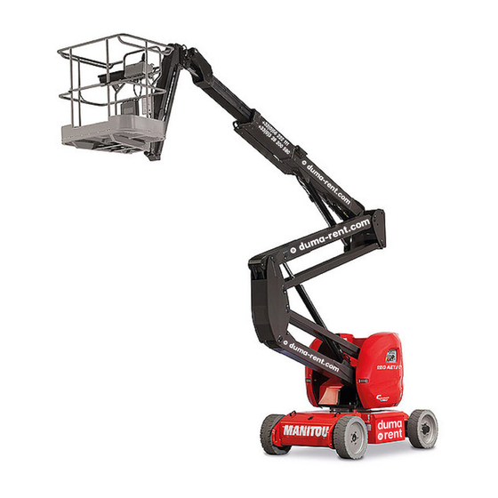
ACCESS PLATFORM
120 AETJ L
150 AETJ C
150 AETJ L
170 AETJ L
OPERATOR’S MANUAL
UNDERSTOOD BY THE OPERATORS.
Related Manuals for Manitou 150 AETJ C
Summary of Contents for Manitou 150 AETJ C
-
Page 1
YOUR DEALER 547378 EN (01 / 06 / 2006) ACCESS PLATFORM 120 AETJ L 150 AETJ C 150 AETJ L 170 AETJ L OPERATOR’S MANUAL THIS INSTRUCTION LEAFLET MUST BE KEPT PERMANENTLY ON THE ACCESS PLATFORM AND BE READ AND… -
Page 2
The platform has been designed and pro- duced to enable you to work at high level in complete safety. Before its delivery, MANITOU and the concessionaire have carefully inspected the platform so that you receive it in perfect operating condition. -
Page 3
1 — OPERATING AND SAFETY INSTRUCTIONS 2 — DESCRIPTION 3 — MAINTENANCE 4 — MAINTENANCE HANDBOOK 06/02/2006 1ST DATE OF ISSUE 01/06/2006 UP DATING (2-6 ; 2-7 ; 2-9 ; 3-9) THE TEXTS AND ILLUSTRATIONS IN THIS DOCUMENT MUST NOT BE REPRODUCED EITHER WHOLLY OR IN PART. -
Page 4
FRONT REAR… -
Page 5
1 — OPERATING 1 — OPERATING AND SAFETY AND SAFETY INSTRUCTIONS INSTRUCTIONS 1 — 1… -
Page 6
1 — 2… -
Page 7: Table Of Contents
TABLE OF CONTENTS 1 — 4 NSTRUCTIONS TO THE COMPANY MANAGER PREAMBLE 1 — 4 THE OPERATOR 1 — 4 THE PLATFORM 1 — 4 A — THE PLATFORM’S SUITABILITY FOR USE 1 — 4 B — ADAPTING THE PLATFORM TO THE USUAL ENVIRONMENTAL CONDITIONS 1 — 4 C — MODIFYING THE PLATFORM 1 — 5…
-
Page 8: Instructions To The Company Manager
A — THE PLATFORM’S SUITABILITY FOR USE — MANITOU has ensured that this platform is suitable for use under the standard operating conditions defined in this ope- rator’s manual, with an overload test coefficient of 1,25 and an operational test coefficient of 1,1, as stipulated in stan- dardised norm EN 280 for MPLP (Mobile Personnel Lifting Platforms).
-
Page 9: C — Modifying The Platform
For operation under average climatic conditions, i.e. : between -15 °C and + 35 °C, correct levels of lubricants in all the circuits are checked in production. For operation under more severe climatic conditions, before starting up, it is necessary to drain all the circuits, then ensure correct levels of lubricants using lubricants properly suited to the relevant ambient temperatures.
-
Page 10: Instructions For The Operator
INSTRUCTIONS FOR THE OPERATOR REAMBLE WHENEVER YOU SEE THIS SYMBOL IT MEANS : WARNING ! BE CAREFUL ! YOUR SAFETY OR THE SAFETY OF THE PLATFORM IS AT RISK. The risk of accident while using, servicing or repairing your platform can be restricted if you follow the safety instructions and safety measures detailed in these instruction.
-
Page 11: C — Maintenance
C — MAINTENANCE — The operator must immediately advise his superior if his platform is not in good working order or does not comply with the safety notice. — The operator is prohibited from carrying out any repairs or adjustments himself, unless he has been trained for this purpose.
-
Page 12: Driving Instructions
— Safety helmets must be worn. — MANITOU recommends a safety harness in the operator’s size be provided when the platform is in use (for the harness attachement in the basket , see 2 — DESCRIPTION : INSTRUMENTS AND CONTROLS).
-
Page 13: D — Visibility
— Do not allow anybody to come near the working area of the platform or pass beneath an elevated load. To do this, mark your operating area with warning signs. — Travelling on a longitudinal slope : • Ensure that you adapt the platform’s travelling speed by controlling the speed with the travelling manipulator. — Take into account the platform’s dimensions and its load before trying to negotiate a narrow or low passageway.
-
Page 14: E — Starting The Platform
E — STARTING THE PLATFORM PLATFORMS WITH IC ENGINES SAFETY NOTICE — Never try to start the platform by pushing or towing it. Such operation may cause severe damage to the transmission. In case of necessity, towing requires the platform to be set for free-wheeling (see : 3 — MAINTENANCE). — If using an emergency battery for start-up, use a battery with the same characteristics and respect battery polarity when connecting it.
-
Page 15: F — Driving The Platform
— If any error messages are constantly displayed or the machine maintenance light is flashing, return the key to the neutral position. — Set the battery cut-off to the OFFposition. — Immediately take the necessary measures. F — DRIVING THE PLATFORM SAFETY NOTICE Operators should be aware of the risks connected with using the platform, notably: — Risk of losing control.
-
Page 16: G — Stopping The Platform
G — STOPPING THE PLATFORM SAFETY NOTICE — Never leave the ignition key in the platform during the operator’s absence. Make sure that the platform is not stopped in any position that will interfere with the traffic flow and at less than one meter from the track of a railway.
-
Page 17: Instructions For Welding And Blow Torch Work On The External Structure
NSTRUCTIONS FOR WELDING AND BLOW TORCH WORK ON THE EXTERNAL STRUCTURE Ensure that there are no hydraulic or electrolyte leaks on the platform. When welding, work in the opposite direction from the control console to avoid sparks damaging it . Any welding and cutting (blow torch) work from the basket on a building’s metallic structures requires the following precautions to be taken: A — WITH ELECTRIC WELDING EQUIPMENT…
-
Page 18: Platform Maintenance Instructions
PLATFORM MAINTENANCE INSTRUCTIONS ENERAL INSTRUCTIONS — Ensure the area is sufficiently ventilated before starting the platform. — Wear clothes suitable for the maintenance of the platform, avoid wearing jewellery and loose clothes. Tie and protect your hair, if necessary. — Stop the engine before conducting any work on the platform, remove the ignition key and disconnect the “Minus” battery terminal.
-
Page 19: Electricity
Ensure that all consumables and replacement parts are disposed of safety, in an environmentally friendly manner. LECTRICITY — Do not drop metallic items on the battery (between the “Plus” and “Minus terminals”). — Disconnect the battery or batteries before working on the electrical circuit. — The electrical box must only be opened by authorized personnel.
-
Page 20: If The Platform Is Not To Be Used For A Long Time
The following recommendations are intended to prevent the platform from being damaged when it is withdrawn from service for an extended period. For these operations, we recommend the use of a MANITOU protective product, reference 603726. Instructions for using the product are given on the packaging.
-
Page 21: Charging The Batteries
HARGING THE BATTERIES — In the case of electric platforms, in order to preserve the batteries’life and their capacity, check them periodically and keep the charge level constant (see : 3 — MAINTENANCE). ROTECTING THE PLATFORM — Protect cylinder rods which will not be retracted, from corrosion. — Wrap the tyres.
-
Page 22: Safety Decals
SAFETY DECALS 14 2 10 14 1 — 18…
-
Page 23
ESCRIPTION 1 — WHITE ARROW 2 — BLACK ARROW 3 — LOAD PER WHEEL 4 — MANUAL CONTROL PROCEDURE 5 — MANUAL CONTROL PROCEDURE FOR ROTATING JIB 6 — BLADE SAFETY INSTRUCTIONS 7 — WASHING RECOMMENDATIONS 8 — ANCHORING HOOK 9 — BASKET INSTRUCTIONS / LOAD CAPACITY 10 — REPLACING THE BATTERIES 11 — BATTERY CUT-OFF / DANGER BATTERY CHARGE / 230 VOLT 16 A SOCKET… -
Page 24
EANING 1. W HITE ARROW This indicates the direction of travelling when moving forwards. When the turret assembly, the arms assembly and the basket make a 180° rotation with respect to the chassis, the travelling controls are reversed. Identify the forward direction by looking at the arrows on the chassis and on the basket control console. -
Page 25
Association of the two operations + 1 : Depending on the movements desired: — Push in and lock the wheel (left-hand bubble) OR pull out and lock the wheel (right-hand bubble) + 1 — Pump. This enables you to perform: Top left column downwards, Top right column downwards, The five movements below:… -
Page 26
6. B LADE SAFETY INSTRUCTIONS Take note of the safety and operating instructions before you start the platform. 679311 7. W ASHING RECOMMENDATIONS It is strictly forbidden to direct a pressure washer’s nozzle over the control buttons and electrical components. 598892 A 8. -
Page 27
10. R EPLACING THE BATTERIES This indicates that the weight of the new batteries must be greater than or equal to those you are replacing. If this instruction is not observed, the platform’s stability will be compromised. 677856 ATTERY CUT This indicates the position of the battery cut-out and its effect: Position OFF: le courant ne passe pas. -
Page 28
12. D ANGER KEEP AWAY It is strictly forbidden to cross under or park under the structure (arms, scissors, pendular arm, basket, etc.) and in the area over which the platform operates. 679450 13. R ISK OF SHEARING It is strictly forbidden to place your fingers, or any other part of the body, in the parts of the lifting system (arms, scissors, pendular arm, etc.): risk of being cut or crushed. -
Page 29
2 — DESCRIPTION 2 — DESCRIPTION 2 — 1… -
Page 30
2 — 2… -
Page 31
CONTENTS 2 — 4 LATFORM IDENTIFICATION 2 — 5 HARACTERISTICS 120 AETJ L 2 — 10 IMENSIONS 150 AETJ C 2 — 12 IMENSIONS 150 AETJ L 2 — 14 IMENSIONS 170 AETJ L 2 — 16 IMENSIONS 2 — 19… -
Page 32: Platform Identification
PLATFORM IDENTIFICATION It is our policy to improve our products constantly. Certain modifications may be made to our range of platforms without our being required to advise our customers. On any order for replacement parts or for any technical information, please always specify: NB: To be able to provide all these numbers more easily, we recommend that you write them down in the locations provided for this on receipt of the…
-
Page 33: Characteristics
CHARACTERISTICS LECTRIC PUMP — Power supply 48 V — Power 3,6 KW — Cubic capacity 4,8 cm3 — Pressure 200 bar LECTRICAL WHEELS MOTORS — Type T 17 — 2 KW LECTRICAL CIRCUIT — Battery 48 V — 300 Ah(150AETJC — 150AETJL — 170AETJL) 48 V — 240 Ah (120AETJL) — Charger…
-
Page 34: 120 Aetj L
120 AETJ L PECIFICATIONS — Use Indoors and Outdoors — Capacity 200 Kg including 2 people — Maximum authorized wind speed 45 Km/h — Control system Hydro-electric — Turret rotation 355° — Working speed 0,6 km/h — Speed in transport 5 km/h — Working height 11950 mm…
-
Page 35: 150 Aetj C
150 AETJ C PECIFICATIONS — Use Indoors and Outdoors — Capacity 200 Kg including 2 people — Maximum authorized wind speed 45 Km/h — Control system Hydro-electric — Turret rotation 355° — Working speed 0,6 km/h — Speed in transport…
-
Page 36: 150 Aetj L
150 AETJ L PECIFICATIONS — Use Indoors and Outdoors — Capacity 230 Kg including 2 people — Maximum authorized wind speed 45 Km/h — Control system Hydro-electric — Turret rotation 355° — Working speed 0,6 km/h — Speed in transport 5 km/h — Working height 15280 mm…
-
Page 37: 170 Aetj L
170 AETJ L PECIFICATIONS — Use Indoors and Outdoors — Capacity 200 Kg including 2 people — Maximum authorized wind speed 45 Km/h — Control system Hydro-electric — Turret rotation 355° — Working speed 0,6 km/h — Speed in transport 5 km/h — Working height 16910 mm…
-
Page 38
DIMENSIONS 120AETJ L 5520 3930 2000 1995 2210 1500 2640 1870 3960 4520 2 — 10… -
Page 39
2350 9950 3105 8795 4775 6370 5640 2 — 11… -
Page 40
DIMENSIONS 150AETJ C 6050 4400 2000 1965 2080 1500 2640 1870 3960 4820 2 — 12… -
Page 41
2665 12985 3425 11835 7105 7165 6300 2 — 13… -
Page 42
DIMENSIONS 150AETJ L 5960 4400 2000 1970 2080 1750 2880 1970 4270 4890 2 — 14… -
Page 43
2660 13275 3420 12120 7310 7165 6500 2 — 15… -
Page 44
DIMENSIONS 170AETJ L 6840 5120 2000 1970 2040 1750 2890 2005 4300 5600 2 — 16… -
Page 45
2840 14910 3600 13750 8930 7160 8130 2 — 17… -
Page 46
2 — 18… -
Page 47: Platform Operation
— MANITOU lifting platforms are solely for use for bringing people, and their tools and supplies (within the authorised weight limit, please refer to the paragraph “SPECIFICATIONS”), to a desired working height, to reach hard-to-access locations over installations and buildings.
-
Page 48
AFETY SLOPE When the access platform has reached the maximum authorised inclination (see chapter : CHARACTERISTICS), the LED 23* on the basket console flashes regularly. Furthermore, the beeper 33* in the basket also sounds intermittently. All «AGGRAVATING» movements — raising the arms, extending the telescope movements are prohibited for safety reasons . -
Page 49
INCOHERENCE of OVERLOAD SENSORS, NB : LOW ARM position and TELESCOPE extension / retraction. This memo is to inform you that the slope and overload LEDs may, in certain situations, be activated intermittently and the beeper may sound constantly, for reasons other than excessi- ve slope position or overloaded basket. -
Page 50: Control Instrumentation
CONTROL INSTRUMENTATION A — G ROUND BACKUP AND MAINTENANCE STATION 2 — 22…
-
Page 51
A — G ROUND BACKUP AND MAINTENANCE STATION 1 — EMERGENCY STOP 2 — KEY-OPERATED CONTROL SELECTOR SWITCH AT GROUND LEVEL OR IN THE BASKET 3 — OVERLOAD LAMP 4 — «MAINTENANCE MACHINE» LAMP 5 — «STATE OF CHARGE OF THE BATTERY» LAMP 6 — «DEAD MAN»… -
Page 52
CONTROL INSTRUMENTATION B — B ASKET COMMAND AND CONTROL STATION 2 — 24… -
Page 53
B — B ASKET COMMAND AND CONTROL STATION 21 — EMERGENCY STOP 22 — OVERLOAD LAMP AND VARIATOR DEFECTS 23 — SLOPE LAMP 24 — SOUND ALARM HORN 25 — CONTROL SWITCH 26 — CONTACTOR OF SELECTION OF ROTATION 27 — PLATFORM INCLINATION CONTACTOR 28 — EXTENSION ARM LIFTING / LOWERING CONTACTOR 29 — TELESCOPE OUTPUTS / INPUTS CONTACTOR 30 — SUPERIOR ARM LIFTING / RAISING CONTACTOR… -
Page 54: Ground Backup And Maintenance Station
GROUND BACKUP AND MAINTENANCE STATION 1 — E MERGENY STOP This red mushroom-head switch cuts off all the machine’s movements in the event of any anomalies or danger. — Press the knob to stop the machine’s movements. — Turn the knob a quarter of a turn to the right to restore the power (the switch automatically returns to its initial position).
-
Page 55
4 — “M ” AINTENANCE MACHINE LAMP — THIS LAMP HAS TWO FUNCTIONS: This lamp is controlled by a timer, which brings it on every 50 hours worked (Counting of the number of hours the hydraulic pump has operated). When the lamp is on (fixed LED), this mean that the machine must be serviced (see chapter «MAINTENANCE TABLE»). -
Page 56
7 — B ATTERY CHARGE INDICATOR AND THE HORAMETER A — BATTERY CHARGE INDICATOR · BATTERY CHARGED — All the bars are displayed (dark). · BBATTERY DISCHARGED — Only two bars are still displayed, meaning that you must proceed to recharge the batteries (See the Chapter «MAINTENANCE INTERVALS»). -
Page 57
RESETTING THE DAILY HORAMETRE TIMER TO ZERO Proceed as follows: — The platform must be in transport position (arms and telescope completely folded), — The platform must not be sloping, — The platform must be in «Ground backup and maintenance station» position, using selector 2 «key-operated control selector at ground level or in the basket «… -
Page 58
8 — P LATFORM ROTATION CONTACTOR — This contactor is used to rotate the platform. RIGHT ROTATION — Place the base/basket switch in the base position, keep the «dead man» button pushed and push the switch 8 to the right. LEFT ROTATION — Place the base/basket switch in the base position, keep the «dead man»… -
Page 59
13 — R A I S E A N D L O W E R C O N TA C T O R O F T H E INFERIOR ARM — This contactor is used to raise and lower the inferior arm. LIFTING OF THE SUPERIOR ARM — Place the base/basket switch in the base position, keep the «dead man»… -
Page 60
17 — F LASHING LIGHT (OPTION) — The flashing alarm lamp turns on automatically when the platform is travelling, or if a movement is carried out (Lifting, rotation,…). 18 — S LOPE SENSOR — This sensor checks the platform’s inclination. When the platform reaches the maximum authorised inclination (See the Chapter: CHARACTERISTICS), the buzzer (33) sounds intermittently and all the “AGGRAVATING”… -
Page 61: Basket Command And Control Station
BASKET COMMAND AND CONTROL STATION 21 — E MERGENCY STOP This red mushroom-head switch cuts off all the machine’s movements in the event of any anomalies or danger. — Press the knob to stop the machine’s movements. — Turn the knob a quarter of a turn to the right to restore the power (the switch automatically returns to its initial position).
-
Page 62
25 — C ONTROL SWITCH NB: This control switch is progressive control, and gives a very high approa- ch accurancy. Its use should be smooth and free of jerkes. SAFETY TRIGGER — This trigger (item A) of control control switch 25 must be continually pushed in to perform movements from the operating of the access platform. -
Page 63
27 — 28 — 29 — 30 — 31 — 32 — M OVEMENT SELECTION CONTACTOR 27 PLATFORM INCLINATION CONTACTOR — Select the movement by pressing button 27; the movement remains selected while the LED is lit (8 seconds). — Push (forward) or pull (backward) the switch control 25 to raise or lower. NB : The basket can only be tilted when the machine is in transport position. -
Page 64
33 — A LARM BUZZER — This buzzer sounds when the machine is in either of the critical situations below: : ( S e e : A C C E S S P L A T F O R M — C a s e 1 ;… -
Page 65: Use Of The Platform
USE OF THE PLATFORM TRANSPORT POSITION FRONT TRAVELLING REAR TRAVELLING ISPLACEMENT TRANSPORT MODE WORKING MODE B e f o r e m o v i n g a n d u s i n g t h e m a c h i n e , r e m o v e t h e t u r r e t b l o c k i n g TRANSPORT MODE system 1 (see Fig.
-
Page 66
RANSPORT WORK SPEED MODE LIMITATION The pendular arm can raise and lower in transport speed mode with the telescope retracted. Raise to the maximum, up to 5cm Details on changing from transport speed to working speed: Extend the telescope less than 2cm and the lower arms to the stop (raised <… -
Page 67
OADING AND UNLOADING OF THE ACCESS PLATFORM Check that the safety instructions associated with the flatbed are being obser- ved before loading the access platform, and make sure that the truck driver is informed about the dimensional characteristics and the weight of the access platform. -
Page 68
UNLOADING Never drive down from a truck in forward gear (counterweight to the front above the steerable wheels), the low adhesion of the rear wheels would reduce braking power. Ensure that you adapt the platform’s travelling speed by controlling the speed with the travelling manipulator. 2 — 40… -
Page 69: Rescue Procedure
RESCUE PROCEDURE This paragraph describes the procedures to be followed and the controls to be used if a problem arises (the platform breaks down or someone is trapped in the basket) while the platform is operating. When taking charge of the machine and at regular intervals afterwards, the operator (and anyone else whose duties are centred on activities in contact with the machine) should read and fully understand this procedure.
-
Page 70
Diagram of the functions of the distributor: 679307 2 — 42… -
Page 71
ROCEDURE OF FREE WHEELING The platform may only be towed a short distance and only by a machine with significant braking performance, in order to hold it: the two machines must be connected by a tow bar. — To set the platform to free wheel, it must not be subject to any travelling stresses from slopes. -
Page 72
2 — 44… -
Page 73
3 — MAINTENANCE 3 — MAINTENANCE 3 — 1… -
Page 74
3 — 2… -
Page 75
TABLE OF CONTENTS MANITOU 3 — 5 ORIGINAL SPARE PARTS AND EQUIPMENT 3 — 7 ILTER ELEMENT 3 — 7 UBRICANTS 3 — 9 AINTENANCE SCHEDULE A — E 3 — 10 VERY DAY OR EVERY HOURS OF OPERATION B — E… -
Page 76
3 — 4… -
Page 77: Manitou Original Spare Parts And Equipment
— improvements due to experience feedback. — operator training. — Only the MANITOU network is familiar with the details of the platform design and is therefore technically the best qualified to provide maintenance services. ORIGINAL REPLACEMENT PARTS ARE DISTRIBUTED EXCLUSIVELY BY MANITOU AND ITS DEALER NETWORK.
-
Page 78
3 — 6… -
Page 79: Lubricants
599004 100 H LUBRICANTS DEVICES TO BE LUBRICATED CAPACITY RECOMMENDATION PACK REFERENCE HYDRAULIC OIL TANK 12 Litres HYDRAULIC MANITOU 20 L. 582 297 ISO 46 oil 55 L. 546 108 209 L. 546 109 WHEEL REDUCING (EACH) 0.8 Litres SHELL SPIRAX 2 L.
-
Page 80
3 — 8… -
Page 81: Maintenance Schedule
MAINTENANCE SCHEDULE A = ADJUST After N = CLEAN C = CHECK the first Day or hours or hours hours P = PURGE Ch = LOAD 5 hours or 1 or 2 R = REPLACE D = DESCALE hours months* year* years* V = EMPTY…
-
Page 82: A — Every Day Or Every 5 Hours Of Operation
A — EVERY DAY OR EVERY 5 HOURS OF OPERATION A1 — B A1/1 ATTERY CHARGE CHECK The platform has 5 hours of effective autonomy, with batteries fully charged. When all the sections of the dial 1 (Fig. A1/1) are black, this indicates that the batteries are fully charged.
-
Page 83
A3 — H YDRAULIC OIL LEVEL CHECK — Open the left hand cowling. — Set the platform in transport position — The oil level should reach the middle of signal light 1 (Fig. A3). — If necessary, add oil (see chapter “LUBRICANTS”) via the fill orifice A (Fig. A3). -
Page 84
A6 — B ATTERY BOXES A6/1 EMPTY — Stop the access platform. — Remove the battery caps. — Make sure there is water in the battery boxes by connecting the aspirator bulb 1 (Fig. A6/1) to pipe 2 (Fig. A6/2) — Drain the water from the boxes. -
Page 85: B — Every 50 Hours Of Operation
B — EVERY 50 HOURS OF OPERATION B1 — S HAFTS GREASE — Clean, then grease the following points with grease, (See chapter: “LUBRICANTS”) and remove the excess. Legend: Axle stop Penstock 2 points of greasing 1 point of 2 points of greasing greasing 4 points of…
-
Page 86
B2 — T IGHTENING WHEELNUTS CHECK TIGHTENING TORQUE OF THE WHEEL NUTS — Check the wheel nuts are tight (Fig. B2). Not applying this recommendation can lead to the deterioration and breaking 34 daN/m of the wheel bolts, as well as the deformation of the wheels. FRONT WHEELS ±… -
Page 87: C — Every 100 Hours Of Operation
C — EVERY 100 HOURS OF OPERATION C1 — A CCESS PLATFORM SLEW RING C1/1 GREASE — The greasing of the bearing tracks and lubrication of the teeth shoul be carried out every 100 hours of operation, and also before and after a long period of non use.
-
Page 88
C3 — R EAR WHEEL REDUCER OIL C3/1 EMPTY — REPLACE — Place the access platform on an horizontal ground in transportation position and the warm oil of the reducings. — Raise the back of the platform (using the two sling eyeholes (Fig. C3/1) or any other means of lifting). -
Page 89
C4 — H YDRAULIC OIL C4/1 EMPTY — REPLACE C5 — H YDRAULIC CIRCUIT STRAINER CLEAN — Place the access platform on an horizontal ground in transportation position. — Open the left hand cowling. DRAIN OF THE OIL — Place a tray underneath the drain orifice 1 (Fig. C4/1) and unscrew this. — Remove the fill cap 3 (Fig. -
Page 90
C7 — T IGHTENING TURRET ROTATION MOTOR BOLTS C7/1 CHECK Set the platform on a horizontal surface. — Open the left hand cowling. — Check the tightness of the nine bolts 1 (Fig. C7/1). — The tightening torque for the bolts is 8 daN.m ± 10%. — 1 daN = 1 Kg C8 — T URRET MOTOR BRAKE REDUCER… -
Page 91: D — Occasional Maintenance
D — OCCASIONAL MAINTENANCE D1 — B ATTERIES REPLACE When it is necessary to replace the battery, it is important to use the batteries with same capacity and weight to guarantee the stability of the machine. A traction battery is heavy (265 Kg), so a mechanical lifting system must be used. PRECAUTION : — Maintain the battery in vertical position during the lifting.
-
Page 92
3 — 20… -
Page 93
4 — MAINTENANCE 4 — MAINTENANCE HANDBOOK HANDBOOK 4 — 1… -
Page 95
MAINTENANCE HANDBOOK — The maintenance handbook is provided by MANITOU’s dealer when the machine is put into service. — It accompanies the machine throughout the guarantee period and subsequently enables regular monitoring of the maintenance conducted on the machine in accordance with MANITOU’s recommendations. -
Page 96
DATE ACTUAL HOURS ENGINEER’S SIGNATURE 250 HOURS DEALER’S STAMP REMARKS: DATE ACTUAL HOURS ENGINEER’S SIGNATURE HOURS DEALER’S STAMP REMARKS: DATE ACTUAL HOURS ENGINEER’S SIGNATURE 350 HOURS DEALER’S STAMP REMARKS: DATE ACTUAL HOURS ENGINEER’S SIGNATURE HOURS DEALER’S STAMP REMARKS: DATE ACTUAL HOURS ENGINEER’S SIGNATURE HOURS DEALER’S STAMP… -
Page 97
DATE ACTUAL HOURS ENGINEER’S SIGNATURE 550 HOURS DEALER’S STAMP REMARKS: DATE ACTUAL HOURS ENGINEER’S SIGNATURE HOURS DEALER’S STAMP REMARKS: DATE ACTUAL HOURS ENGINEER’S SIGNATURE 650 HOURS DEALER’S STAMP REMARKS: DATE ACTUAL HOURS ENGINEER’S SIGNATURE HOURS DEALER’S STAMP REMARKS: DATE ACTUAL HOURS ENGINEER’S SIGNATURE 750 HOURS DEALER’S STAMP… -
Page 98
DATE ACTUAL HOURS ENGINEER’S SIGNATURE HOURS DEALER’S STAMP REMARKS: DATE ACTUAL HOURS ENGINEER’S SIGNATURE HOURS DEALER’S STAMP REMARKS: DATE ACTUAL HOURS ENGINEER’S SIGNATURE 950 HOURS DEALER’S STAMP REMARKS: DATE ACTUAL HOURS ENGINEER’S SIGNATURE 1000 HOURS DEALER’S STAMP REMARKS: DATE ACTUAL HOURS ENGINEER’S SIGNATURE 1050 HOURS DEALER’S STAMP… -
Page 99
DATE ACTUAL HOURS ENGINEER’S SIGNATURE HOURS DEALER’S STAMP REMARKS: DATE ACTUAL HOURS ENGINEER’S SIGNATURE HOURS DEALER’S STAMP REMARKS: DATE ACTUAL HOURS ENGINEER’S SIGNATURE HOURS DEALER’S STAMP REMARKS: DATE ACTUAL HOURS ENGINEER’S SIGNATURE HOURS DEALER’S STAMP REMARKS: DATE ACTUAL HOURS ENGINEER’S SIGNATURE HOURS DEALER’S STAMP REMARKS:… -
Page 100
DATE ACTUAL HOURS ENGINEER’S SIGNATURE HOURS DEALER’S STAMP REMARKS: DATE ACTUAL HOURS ENGINEER’S SIGNATURE HOURS DEALER’S STAMP REMARKS: DATE ACTUAL HOURS ENGINEER’S SIGNATURE HOURS DEALER’S STAMP REMARKS: DATE ACTUAL HOURS ENGINEER’S SIGNATURE HOURS DEALER’S STAMP REMARKS: DATE ACTUAL HOURS ENGINEER’S SIGNATURE HOURS DEALER’S STAMP REMARKS:… -
Page 101
DATE ACTUAL HOURS ENGINEER’S SIGNATURE HOURS DEALER’S STAMP REMARKS: DATE ACTUAL HOURS ENGINEER’S SIGNATURE HOURS DEALER’S STAMP REMARKS: DATE ACTUAL HOURS ENGINEER’S SIGNATURE HOURS DEALER’S STAMP REMARKS: DATE ACTUAL HOURS ENGINEER’S SIGNATURE HOURS DEALER’S STAMP REMARKS: DATE ACTUAL HOURS ENGINEER’S SIGNATURE HOURS DEALER’S STAMP REMARKS:…
-
Dannmar Equipment Max Jax
1Installation and Operation6,000 P6,000 Pound Capacityound CapacityPPortable Two-Post Liftortable Two-Post LiftSafetyYour new lift was designed and built with safety in mind; however, your overall safety can be increased by proper training and thoughtful operation. DO NOT operate or repair this machine without reading …
Max Jax Lifting Systems, 28
-
Permaquip Ironman
MAN-M-O-105_19 26/02/2016 Page 1 of 44 Operating & Maintenance Manual Ironman (Standard and LUL) Permaquip Ltd Brierley Industrial Park, Stanton Hill, Sutton-in-Ashfield Nottinghamshire, NG17 3JZ Tel: +44 (0) 1623 513349 Fax: +44 (0) 1623 517742 E-mail: [email protected] www.permaquip.co.uk …
Ironman Lifting Systems, 44
-
Jet SLT-1100
Operating Instructions and Parts Manual SLT-1100 Jumbo Scissor Lift Table For serial no. 17020001 and higher JET 427 New Sanford Road LaVergne, Tennessee 37086 Part No. M-140780 Ph.: 800-274-6848 Revision C 03/2017 www.jettools.com Copyright © 2017 JET …
SLT-1100 Lifting Systems, 12
-
Blue Giant INTERLOCK CHOCK
ACTUAL PRODUCT MAY NOT APPEAR EXACTLY AS SHOWNSTARTING FROM AUGUST 14, 2020 / SERIAL # 467201ISSUE DATE: OCTOBER 20, 2021 REV. 1.2.1 (PART # 038-1125E)BLUE GIANT INTERLOCK CHOCK™OWNER’S MANUALWARNINGDo not operate or service this product unless you have read and fully understand the entire contents of this manual. …
INTERLOCK CHOCK Lifting Systems, 40
-
Hydra-slide LP350
SKIDDING RIGGING HYDRAULICSLOW PROFILE SKIDDING SYSTEMMODEL:LP350March 2018Hydra-Slide Ltd.84 Royal Rd.,Guelph, ON. N1H 1G3Canadahydra-slide.comPLEASE READ OPERATING MANUAL BEFOREUSING THIS EQUIPMENT AND ADHERE TO ALLSAFETY INSTRUCTIONS. FOR QUESTIONSCONTACT HYDRA-SLIDE LTD. AT 519-830-7517. …
LP350 Lifting Systems, 50
-
Superwinch X1
…
X1 Lifting Systems, 14
-
Paragon Pro Doorminator 3070
WARNING© 2018 Paragon Pro Manufacturing Solutions All Rights ReservedRead and become familiar with this manual BEFORE operating unit.Before operating this equipment, thoroughly read this set of instructions, make sure you understand them, and only then follow the step-by-step directions. Failure to do so could result …
Doorminator 3070 Lifting Systems, 12
-
Liko Viking S
Instruction guide7EN138101-012005-06-28Viking S is appropriate for all common lifting situations; e.g., transfers between bed and wheelchair, to and from the toilet and bathtub or for lifting to and from the oor. For optimal function and safety, it is essential that the lift and any accessories you intend to use be …
Viking S Fitness Equipment, 12
Download or browse on-line these Operator’s Manual for Manitou 150 AETJ C Boom Lifts, Lifting Systems.
Summary of Contents:
 |
[Page 1] Manitou 150 AETJ C ACCESS PLATFORM 120 AETJ L 150 AETJ C 150 AETJ L 170 AETJ L 547378 EN (01 / 06 / 2006) BP 249 Z. I. 44158 ANCENIS CEDEX — FRANCE TEL : 33 (0)2 40 09 10 11 YOUR DEALER OPERATOR’S MANUAL THIS INSTRUCTION LEAFLET MUST BE KEPT PERMANENTLY ON THE A… |
 |
[Page 2] Manitou 150 AETJ C PREAMBLE This instructions manual is designed to explain how to operate the machine and the maintenan- ce required periodically for the machine to continue to operate in complete safety. The platform has been designed and pro- duced to enable you to … |
 |
[Page 3] Manitou 150 AETJ C THE TEXTS AND ILLUSTRATIONS IN THIS DOCUMENT MUST NOT BE REPRODUCED EITHER WHOLLY OR IN PART. 1 — OPERATING AND SAFETY INSTRUCTIONS 2 — DESCRIPTION 3 — MAINTENANCE 4 — MAINTENANCE HANDBOOK 06/02/2006 01/06/2006 1ST DATE OF ISSUE UP DATING (2-6 ; 2-7 … |
 |
[Page 4] Manitou 150 AETJ C REAR FRONT |
 |
[Page 5] Manitou 150 AETJ C 1 — OPERATING AND SAFETY INSTRUCTIONS 1 — OPERATING AND SAFETY INSTRUCTIONS 1 — 1 |
 |
[Page 6] Manitou 150 AETJ C 1 — 2 |
 |
[Page 7] Manitou 150 AETJ C 1 — 3 TABLE OF CONTENTS INSTRUCTIONS TO THE COMPANY MANAGER PREAMBLE THE OPERATOR THE PLATFORM A — THE PLATFORM’S SUITABILITY FOR USE B — ADAPTING THE PLATFORM TO THE USUAL ENVIRONMENTAL CONDITIONS C — MODIFYING THE PLATFORM THE INSTRUCTIONS THE MA… |
 |
[Page 8] Manitou 150 AETJ C 1 — 4 INSTRUCTIONS TO THE COMPANY MANAGER PREAMBLE THE OPERATOR — Only qualified, authorized personnel can use the platform. This authorization is given in writing by the appropriate per- son in the establishment with respect to the use of platform a… |
 |
[Page 9] Manitou 150 AETJ C 1 — 5 For operation under average climatic conditions, i.e. : between -15 °C and + 35 °C, correct levels of lubricants in all the circuits are checked in production. For operation under more severe climatic conditions, before starting up, it is nec… |
 |
[Page 10] Manitou 150 AETJ C 1 — 6 INSTRUCTIONS FOR THE OPERATOR PREAMBLE The risk of accident while using, servicing or repairing your platform can be restricted if you follow the safety instructions and safety measures detailed in these instruction. — Only the operations and m… |
 |
[Page 11] Manitou 150 AETJ C 1 — 7 C — MAINTENANCE — The operator must immediately advise his superior if his platform is not in good working order or does not comply with the safety notice. — The operator is prohibited from carrying out any repairs or adjustments himself, unles… |
 |
[Page 12] Manitou 150 AETJ C 1 — 8 DRIVING INSTRUCTIONS A — BEFORE STARTING THE PLATFORM — Ensure that the intermediate rail is fully in the locked position before operating the platform from the basket. — If the platform is new, see the Chapter : BEFORE STARTING THE PLATFORM FO… |
 |
[Page 13] Manitou 150 AETJ C 1 — 9 — Do not allow anybody to come near the working area of the platform or pass beneath an elevated load. To do this, mark your operating area with warning signs. — Travelling on a longitudinal slope : • Ensure that you adapt the platform’s tr… |
 |
[Page 14] Manitou 150 AETJ C 1 — 10 E — STARTING THE PLATFORM PLATFORMS WITH IC ENGINES SAFETY NOTICE — Never try to start the platform by pushing or towing it. Such operation may cause severe damage to the transmission. In case of necessity, towing requires the platform to be s… |
 |
[Page 15] Manitou 150 AETJ C 1 — 11 — If any error messages are constantly displayed or the machine maintenance light is flashing, return the key to the neutral position. — Set the battery cut-off to the OFFposition. — Immediately take the necessary measures. F — DRIVING THE PLA… |
 |
[Page 16] Manitou 150 AETJ C 1 — 12 G — STOPPING THE PLATFORM SAFETY NOTICE — Never leave the ignition key in the platform during the operator’s absence. — Make sure that the platform is not stopped in any position that will interfere with the traffic flow and at less than … |
 |
[Page 17] Manitou 150 AETJ C 1 — 13 INSTRUCTIONS FOR WELDING AND BLOW TORCH WORK ON THE EXTERNAL STRUCTURE Ensure that there are no hydraulic or electrolyte leaks on the platform. When welding, work in the opposite direction from the control console to avoid sparks damaging it …. |
 |
[Page 18] Manitou 150 AETJ C 1 — 141 — 14 GENERAL INSTRUCTIONS — Ensure the area is sufficiently ventilated before starting the platform. — Wear clothes suitable for the maintenance of the platform, avoid wearing jewellery and loose clothes. Tie and protect your hair, if necessa… |
 |
[Page 19] Manitou 150 AETJ C 1 — 15 Ensure that all consumables and replacement parts are disposed of safety, in an environmentally friendly manner. ELECTRICITY — Do not drop metallic items on the battery (between the “Plus” and “Minus terminals”). — Disconnect the batt… |
 |
[Page 20] Manitou 150 AETJ C 1 — 16 INTRODUCTION The following recommendations are intended to prevent the platform from being damaged when it is withdrawn from service for an extended period. For these operations, we recommend the use of a MANITOU protective product, reference … |
 |
[Page 21] Manitou 150 AETJ C 1 — 17 CHARGING THE BATTERIES — In the case of electric platforms, in order to preserve the batteries’life and their capacity, check them periodically and keep the charge level constant (see : 3 — MAINTENANCE). PROTECTING THE PLATFORM — Protect cyl… |
 |
[Page 22] Manitou 150 AETJ C 1 — 18 SAFETY DECALS 15 10 14 8 31214 1 13 7 814 12 14 4 5 9 12 714 1011 3 6 14 2 33 13 |
 |
[Page 23] Manitou 150 AETJ C 1 — 19 DESCRIPTION 1 — WHITE ARROW 2 — BLACK ARROW 3 — LOAD PER WHEEL 4 — MANUAL CONTROL PROCEDURE 5 — MANUAL CONTROL PROCEDURE FOR ROTATING JIB 6 — BLADE SAFETY INSTRUCTIONS 7 — WASHING RECOMMENDATIONS 8 — ANCHORING HOOK 9 — BASKET INSTRUCTIONS / LO… |
 |
[Page 24] Manitou 150 AETJ C 1 — 20 679307 2 3 2 1 3 1 1 4 MEANING 1. WHITE ARROW This indicates the direction of travelling when moving forwards. When the turret assembly, the arms assembly and the basket make a 180° rotation with respect to the chassis, the travelling contr… |
 |
[Page 25] Manitou 150 AETJ C 1 — 21 Association of the two operations 2 + 1 : Depending on the movements desired: 2 — Push in and lock the wheel (left-hand bubble) OR pull out and lock the wheel (right-hand bubble) + 1 — Pump. This enables you to perform: Top left column … |
 |
[Page 26] Manitou 150 AETJ C 1 — 22 230 Kg = 70 Kg + 508 Lbs = 155 Lbs + 2 ! 12,5 m/s (45 km/h) 3° 400 N (40 Kg — 90 Lbs) 679309 679311 ! 6. BLADE SAFETY INSTRUCTIONS Take note of the safety and operating instructions before you start the platform. 7. WASHING RECOMMENDATIONS … |
 |
[Page 27] Manitou 150 AETJ C 1 — 23 10. REPLACING THE BATTERIES This indicates that the weight of the new batteries must be greater than or equal to those you are replacing. If this instruction is not observed, the platform’s stability will be compromised. 11 A. BATTERY CUT-OF… |
 |
[Page 28] Manitou 150 AETJ C 1 — 24 12. DANGER : KEEP AWAY It is strictly forbidden to cross under or park under the structure (arms, scissors, pendular arm, basket, etc.) and in the area over which the platform operates. 13. RISK OF SHEARING It is strictly forbidden to place yo… |
 |
[Page 29] Manitou 150 AETJ C 2 — 1 2 — DESCRIPTION 2 — DESCRIPTION |
 |
[Page 30] Manitou 150 AETJ C 2 — 2 |
 |
[Page 31] Manitou 150 AETJ C 2 — 3 CONTENTS PLATFORM IDENTIFICATION CHARACTERISTICS DIMENSIONS 120 AETJ L DIMENSIONS 150 AETJ C DIMENSIONS 150 AETJ L DIMENSIONS 170 AETJ L PLATFORM OPERATION CONTROL INSTRUMENTATION GROUND BACKUP AND MAINTENANCE STATION BASKET COMMAND AND CONTROL… |
 |
[Page 32] Manitou 150 AETJ C 2 — 4 It is our policy to improve our products constantly. Certain modifications may be made to our range of platforms without our being required to advise our customers. On any order for replacement parts or for any technical information, please alw… |
 |
[Page 33] Manitou 150 AETJ C 2 — 5 ELECTRIC PUMP — Power supply 48 V — Power 3,6 KW — Cubic capacity 4,8 cm3 — Pressure 200 bar ELECTRICAL WHEELS MOTORS — Type T 17 — 2 KW ELECTRICAL CIRCUIT — Battery 48 V — 300 Ah(150AETJC — 150AETJL — 170AETJL) 48 V — 240 Ah (120AETJL) — Ch… |
 |
[Page 34] Manitou 150 AETJ C 2 — 6 TYRES Wheel nut tightening torque ; front wheels 34 daNm Wheel nut tightening torque ; rear wheels 22 daNm 120 AETJ L SPECIFICATIONS — Use Indoors and Outdoors — Capacity 200 Kg including 2 people — Maximum authorized wind speed 45 Km/h — Cont… |
 |
[Page 35] Manitou 150 AETJ C 2 — 7 TYRES Wheel nut tightening torque ; front wheels 34 daNm Wheel nut tightening torque ; rear wheels 22 daNm 150 AETJ C SPECIFICATIONS — Use Indoors and Outdoors — Capacity 200 Kg including 2 people — Maximum authorized wind speed 45 Km/h — Cont… |
 |
[Page 36] Manitou 150 AETJ C TYRES Wheel nut tightening torque ; front wheels 34 daNm Wheel nut tightening torque ; rear wheels 22 daNm 2 — 8 150 AETJ L SPECIFICATIONS — Use Indoors and Outdoors — Capacity 230 Kg including 2 people — Maximum authorized wind speed 45 Km/h — Cont… |
 |
[Page 37] Manitou 150 AETJ C 2 — 9 TYRES Wheel nut tightening torque ; front wheels 34 daNm Wheel nut tightening torque ; rear wheels 22 daNm 170 AETJ L SPECIFICATIONS — Use Indoors and Outdoors — Capacity 200 Kg including 2 people — Maximum authorized wind speed 45 Km/h — Cont… |
 |
[Page 38] Manitou 150 AETJ C 2 — 10 DIMENSIONS 120AETJ L D E B C F H G I A1A1 C1 A A 5520 A1 3930 B 2000 C 1995 C1 2210 D 1500 E 153 F 2640 G 1870 H 3960 I 4520 |
 |
[Page 39] Manitou 150 AETJ C 2 — 11 G1 G2 H2 H1 G3 H3 G4 H4 12 11 10 9 8 7 6 5 4 3 2 1 4567 13 3210123 52332 674 G1 2350 G2 3105 G3 6370 G4 5640 H1 9950 H2 8795 H3 4775 H4 545 |
 |
[Page 40] Manitou 150 AETJ C 2 — 12 DIMENSIONS 150AETJ C D E F H G I B C1 A1 C A A 6050 A1 4400 B 2000 C 1965 C1 2080 D 1500 E 143 F 2640 G 1870 H 3960 I 4820 |
 |
[Page 41] Manitou 150 AETJ C 2 — 13 G1 G2 H2 H1 G3 H3 G4 H4 897 12 11 10 9 8 7 6 5 4 3 2 1 456789 16 15 14 13 3210123 2332 G1 2665 G2 3425 G3 7105 G4 6300 H1 12985 H2 11835 H3 7165 H4 235 |
 |
[Page 42] Manitou 150 AETJ C D E FH G I B A1 A C C1 2 — 14 DIMENSIONS 150AETJ L A 5960 A1 4400 B 2000 C 1970 C1 2080 D 1750 E 143 F 2880 G 1970 H 4270 I 4890 |
 |
[Page 43] Manitou 150 AETJ C G1 G2 H2 H1 G3 H3 G4 H4 89 12 11 10 9 8 7 6 5 4 3 2 1 456789 16 15 14 13 3210123 52332 2 — 15 G1 2660 G2 3420 G3 7310 G4 6500 H1 13275 H2 12120 H3 7165 H4 205 |
 |
[Page 44] Manitou 150 AETJ C D E FH G I B A1 A C C1 2 — 16 DIMENSIONS 170AETJ L A 6840 A1 5120 B 2000 C 1970 C1 2040 D 1750 E 143 F 2890 G 2005 H 4300 I 5600 |
 |
[Page 45] Manitou 150 AETJ C G1 G2 H2 H1 G4 910 10 12 11 10 9 8 7 6 5 4 3 2 1 456789 16 17 15 14 13 3210123 2332 64 H4 G3 H3 2 — 17 G1 2840 G2 3600 G3 8930 G4 8130 H1 14910 H2 13750 H3 7160 H4 270 |
 |
[Page 46] Manitou 150 AETJ C 2 — 18 |
 |
[Page 47] Manitou 150 AETJ C 2 — 19 PLATFORM OPERATION DESCRIPTION — This machine is a mobile platform for lifting people. It consists of a work platform fastened to the end of a pendular arm, itself fastened to the end of a telescopic arm and the whole assembly is fastened to a… |
 |
[Page 48] Manitou 150 AETJ C 2 — 20 SAFETY SLOPE When the access platform has reached the maximum authorised inclination (see chapter : CHARACTERISTICS), the LED 23* on the basket console flashes regularly. Furthermore, the beeper 33* in the basket also sounds intermittently. Al… |
 |
[Page 49] Manitou 150 AETJ C 2 — 21 NB : INCOHERENCE of OVERLOAD SENSORS, LOW ARM position and TELESCOPE extension / retraction. This memo is to inform you that the slope and overload LEDs may, in certain situations, be activated intermittently and the beeper may sound con… |
 |
[Page 50] Manitou 150 AETJ C 2 — 22 CONTROL INSTRUMENTATION A- GROUND BACKUP AND MAINTENANCE STATION 17 16 18 19 20 15 8 10 14 3 4 5 6 9 11 12 13 1 2 7 |
 |
[Page 51] Manitou 150 AETJ C 2 — 23 A- GROUND BACKUP AND MAINTENANCE STATION 1 — EMERGENCY STOP 2 — KEY-OPERATED CONTROL SELECTOR SWITCH AT GROUND LEVEL OR IN THE BASKET 3 — OVERLOAD LAMP 4 — «MAINTENANCE MACHINE» LAMP 5 — «STATE OF CHARGE OF THE BATTERY» LA… |
 |
[Page 52] Manitou 150 AETJ C 2 — 24 CONTROL INSTRUMENTATION B — BASKET COMMAND AND CONTROL STATION 25 27 28 26 24 34 34 29 30 22 23 33 31 21 32 35 |
 |
[Page 53] Manitou 150 AETJ C 2 — 25 B — BASKET COMMAND AND CONTROL STATION 21 — EMERGENCY STOP 22 — OVERLOAD LAMP AND VARIATOR DEFECTS 23 — SLOPE LAMP 24 — SOUND ALARM HORN 25 — CONTROL SWITCH 26 — CONTACTOR OF SELECTION OF ROTATION 27 — PLATFORM INCLINATION CONTACTOR 28 — EXTE… |
 |
[Page 54] Manitou 150 AETJ C 2 — 26 1 — EMERGENY STOP This red mushroom-head switch cuts off all the machine’s movements in the event of any anomalies or danger. — Press the knob to stop the machine’s movements. — Turn the knob a quarter of a turn to the right to restore th… |
 |
[Page 55] Manitou 150 AETJ C 2 — 27 4 — “MAINTENANCE MACHINE” LAMP — THIS LAMP HAS TWO FUNCTIONS: 1 This lamp is controlled by a timer, which brings it on every 50 hours worked (Counting of the number of hours the hydraulic pump has operated). When the lamp is on (fixed LED)… |
 |
[Page 56] Manitou 150 AETJ C 2 — 28 7 — BATTERY CHARGE INDICATOR AND THE HORAMETER A — BATTERY CHARGE INDICATOR · BATTERY CHARGED — All the bars are displayed (dark). · BBATTERY DISCHARGED — Only two bars are still displayed, meaning that you must proceed to recharge the batte… |
 |
[Page 57] Manitou 150 AETJ C 2 — 29 RESETTING THE DAILY HORAMETRE TIMER TO ZERO Proceed as follows: — The platform must be in transport position (arms and telescope completely folded), — The platform must not be sloping, — The platform must be in «Ground backup and mainten… |
 |
[Page 58] Manitou 150 AETJ C 2 — 30 8 — PLATFORM ROTATION CONTACTOR — This contactor is used to rotate the platform. RIGHT ROTATION — Place the base/basket switch in the base position, keep the «dead man» button pushed and push the switch 8 to the right. LEFT ROTATION … |
 |
[Page 59] Manitou 150 AETJ C 2 — 31 13 — RAISE AND LOWER CONTACTOR OF THE INFERIOR ARM — This contactor is used to raise and lower the inferior arm. LIFTING OF THE SUPERIOR ARM — Place the base/basket switch in the base position, keep the «dead man» button pushed and p… |
 |
[Page 60] Manitou 150 AETJ C 2 — 32 17 — FLASHING LIGHT (OPTION) — The flashing alarm lamp turns on automatically when the platform is travelling, or if a movement is carried out (Lifting, rotation,…). 18 — SLOPE SENSOR — This sensor checks the platform’s inclination. When t… |
 |
[Page 61] Manitou 150 AETJ C 2 — 33 21 — EMERGENCY STOP This red mushroom-head switch cuts off all the machine’s movements in the event of any anomalies or danger. — Press the knob to stop the machine’s movements. — Turn the knob a quarter of a turn to the right to restore … |
 |
[Page 62] Manitou 150 AETJ C 2 — 34 25 — CONTROL SWITCH NB: This control switch is progressive control, and gives a very high approa- ch accurancy. Its use should be smooth and free of jerkes. SAFETY TRIGGER — This trigger (item A) of control control switch 25 must be continuall… |
 |
[Page 63] Manitou 150 AETJ C 2 — 35 27 — 28 — 29 — 30 — 31 — 32 — MOVEMENT SELECTION CONTACTOR 27 PLATFORM INCLINATION CONTACTOR — Select the movement by pressing button 27; the movement remains selected while the LED is lit (8 seconds). — Push (forward) or pull (backward) the s… |
 |
[Page 64] Manitou 150 AETJ C 2 — 36 33 — ALARM BUZZER — This buzzer sounds when the machine is in either of the critical situations below: — Case 1 ; INTERMITTENCE : (See : ACCESS PLATFORM OPERATION — SAFETY INSTRUCTIONS). — Case 2 ; CONTINUOUS : (See : ACCESS PLATFORM OPERATION… |
 |
[Page 65] Manitou 150 AETJ C 2 — 37 DISPLACEMENT TRANSPORT MODE / WORKING MODE Before moving and using the machine, remove the turret blocking system 1 (see Fig. A). The contactor 2 (Fig. B) should be in the position A (transfer of commands on the desk of the platform). The acce… |
 |
[Page 66] Manitou 150 AETJ C 2 — 38 TRANSPORT / WORK SPEED MODE LIMITATION The pendular arm can raise and lower in transport speed mode with the telescope retracted. Details on changing from transport speed to working speed: Extend the telescope less than 2cm and the lower arms … |
 |
[Page 67] Manitou 150 AETJ C 2 — 39 LOADING AND UNLOADING OF THE ACCESS PLATFORM Check that the safety instructions associated with the flatbed are being obser- ved before loading the access platform, and make sure that the truck driver is informed about the dimensional characte… |
 |
[Page 68] Manitou 150 AETJ C 2 — 40 UNLOADING Never drive down from a truck in forward gear (counterweight to the front above the steerable wheels), the low adhesion of the rear wheels would reduce braking power. Ensure that you adapt the platform’s travelling speed by contro… |
 |
[Page 69] Manitou 150 AETJ C 2 — 41 This paragraph describes the procedures to be followed and the controls to be used if a problem arises (the platform breaks down or someone is trapped in the basket) while the platform is operating. When taking charge of the machine and at reg… |
 |
[Page 70] Manitou 150 AETJ C 2 — 42 Diagram of the functions of the distributor: 679307 2 1 3 1 4 E |
 |
[Page 71] Manitou 150 AETJ C 2 — 43 PROCEDURE OF FREE WHEELING The platform may only be towed a short distance and only by a machine with significant braking performance, in order to hold it: the two machines must be connected by a tow bar. — To set the platform to free wheel, i… |
 |
[Page 72] Manitou 150 AETJ C 2 — 44 |
 |
[Page 73] Manitou 150 AETJ C 3 — MAINTENANCE 3 — 1 3 — MAINTENANCE |
 |
[Page 74] Manitou 150 AETJ C 3 — 2 |
 |
[Page 75] Manitou 150 AETJ C 3 — 3 TABLE OF CONTENTS MANITOU ORIGINAL SPARE PARTS AND EQUIPMENT FILTER ELEMENT LUBRICANTS MAINTENANCE SCHEDULE A- EVERY DAY OR EVERY 5 HOURS OF OPERATION B — EVERY 50 HOURS OF OPERATION C — EVERY 100 HOURS OF OPERATION D — OCCASIONAL MAINTENANCE 3… |
 |
[Page 76] Manitou 150 AETJ C 3 — 4 |
 |
[Page 77] Manitou 150 AETJ C 3 — 5 OUR ACCESS PLATFORMS MUST BE MAINTAINED WITH ORIGINAL MANITOU PARTS. IF YOU USE PARTS WHICH ARE NOT ORIGINAL MANITOU PARTS, YOU RISK — legally — to be held responsible in the event of an accident. — Causing technical functional failure or redu… |
 |
[Page 78] Manitou 150 AETJ C 3 — 6 |
 |
[Page 79] Manitou 150 AETJ C 3 — 7 FILTER ELEMENT LUBRICANTS DEVICES TO BE LUBRICATED CAPACITY RECOMMENDATION PACK REFERENCE HYDRAULIC OIL TANK 12 Litres HYDRAULIC MANITOU 20 L. 582 297 ISO 46 oil 55 L. 546 108 209 L. 546 109 WHEEL REDUCING (EACH) 0.8 Litres SHELL SPIRAX 2 L. 4… |
 |
[Page 80] Manitou 150 AETJ C 3 — 8 |
 |
[Page 81] Manitou 150 AETJ C 3 — 9 MAINTENANCE SCHEDULE V/R C C** RR C V/R N C V/R C Ch C C C V C G CC G G C C** C** C** C** PAGE 3-16 3-14 3-17 3-11 3-17 3-17 3-14 3-18 3-10 3-10 3-11 3-11 3-14 3-19 3-12 3-12 3-15 3-15 3-13 3-13 3-18 3-12 3-12 3-18 3-12 After the first 50 hours… |
 |
[Page 82] Manitou 150 AETJ C 3 — 10 A1 — BATTERY CHARGE CHECK The platform has 5 hours of effective autonomy, with batteries fully charged. When all the sections of the dial 1 (Fig. A1/1) are black, this indicates that the batteries are fully charged. — When using the access pla… |
 |
[Page 83] Manitou 150 AETJ C 3 — 11 A3 A4/2 A3 — HYDRAULIC OIL LEVEL CHECK — Open the left hand cowling. — Set the platform in transport position — The oil level should reach the middle of signal light 1 (Fig. A3). — If necessary, add oil (see chapter “LUBRICANTS”) via the f… |
 |
[Page 84] Manitou 150 AETJ C 3 — 12 A9 — SLOPE SENSOR CHECK Sensor test (See : 2 — DESCRIPTION : CONTROL SYSTEM INSTRUMENTS, item 19) In the event of malfunction, prohibit use of the platform. Consult your dealer. A10 — M ACHINE STICKERS CHECK (C ONSULT YOUR DEALER) A6 — BATTERY… |
 |
[Page 85] Manitou 150 AETJ C 3 — 13 B — EVERY 50 HOURS OF OPERATION B1 — SHAFTS GREASE — Clean, then grease the following points with grease, (See chapter: “LUBRICANTS”) and remove the excess. Legend: Axle stop Hub Penstock 2 points of greasing 4 points of greasing 1 point o… |
 |
[Page 86] Manitou 150 AETJ C 3 — 14 B2 — T IGHTENING WHEELNUTS CHECK — Check the wheel nuts are tight (Fig. B2). Not applying this recommendation can lead to the deterioration and breaking of the wheel bolts, as well as the deformation of the wheels. B3 — BACKUP PUMP CHECK — St… |
 |
[Page 87] Manitou 150 AETJ C 3 — 15 C1/1 C1/2 C1/3 C1 — ACCESS PLATFORM SLEW RING GREASE — The greasing of the bearing tracks and lubrication of the teeth shoul be carried out every 100 hours of operation, and also before and after a long period of non use. — Grease to be requir… |
 |
[Page 88] Manitou 150 AETJ C 3 — 16 C3 — REAR WHEEL REDUCER OIL EMPTY — REPLACE — Place the access platform on an horizontal ground in transportation position and the warm oil of the reducings. — Raise the back of the platform (using the two sling eyeholes (Fig. C3/1) or any oth… |
 |
[Page 89] Manitou 150 AETJ C 3 — 17 C4 — HYDRAULIC OIL EMPTY — REPLACE C5 — HYDRAULIC CIRCUIT STRAINER CLEAN — Place the access platform on an horizontal ground in transportation position. — Open the left hand cowling. DRAIN OF THE OIL — Place a tray underneath the drain orifice… |
 |
[Page 90] Manitou 150 AETJ C 3 — 18 C7 — T IGHTENING TURRET ROTATION MOTOR BOLTS CHECK Set the platform on a horizontal surface. — Open the left hand cowling. — Check the tightness of the nine bolts 1 (Fig. C7/1). — The tightening torque for the bolts is 8 daN.m ± 10%. — 1 daN … |
 |
[Page 91] Manitou 150 AETJ C 3 — 19 D1 — BATTERIES REPLACE When it is necessary to replace the battery, it is important to use the batteries with same capacity and weight to guarantee the stability of the machine. A traction battery is heavy (265 Kg), so a mechanical lifting sys… |
 |
[Page 92] Manitou 150 AETJ C 3 — 20 |
 |
[Page 93] Manitou 150 AETJ C 4 — 1 4 — MAINTENANCE HANDBOOK 4 — MAINTENANCE HANDBOOK |
 |
[Page 94] Manitou 150 AETJ C … |
 |
[Page 95] Manitou 150 AETJ C 4 — 3 MAINTENANCE HANDBOOK — The maintenance handbook is provided by MANITOU’s dealer when the machine is put into service. — It accompanies the machine throughout the guarantee period and subsequently enables regular monitoring of the maintenance … |
 |
[Page 96] Manitou 150 AETJ C 4 — 4 DATE ACTUAL HOURS ENGINEER’S SIGNATURE 250 HOURS DEALER’S STAMP REMARKS: DATE ACTUAL HOURS ENGINEER’S SIGNATURE 300 HOURS DEALER’S STAMP REMARKS: DATE ACTUAL HOURS ENGINEER’S SIGNATURE 350 HOURS DEALER’S STAMP REMARKS: DATE ACTUAL … |
 |
[Page 97] Manitou 150 AETJ C 4 — 5 DATE ACTUAL HOURS ENGINEER’S SIGNATURE 550 HOURS DEALER’S STAMP REMARKS: DATE ACTUAL HOURS ENGINEER’S SIGNATURE 600 HOURS DEALER’S STAMP REMARKS: DATE ACTUAL HOURS ENGINEER’S SIGNATURE 650 HOURS DEALER’S STAMP REMARKS: DATE ACTUAL H… |
 |
[Page 98] Manitou 150 AETJ C 4 — 6 DATE ACTUAL HOURS ENGINEER’S SIGNATURE 850 HOURS DEALER’S STAMP REMARKS: DATE ACTUAL HOURS ENGINEER’S SIGNATURE 900 HOURS DEALER’S STAMP REMARKS: DATE ACTUAL HOURS ENGINEER’S SIGNATURE 950 HOURS DEALER’S STAMP REMARKS: DATE ACTUAL … |
 |
[Page 99] Manitou 150 AETJ C 4 — 7 DATE ACTUAL HOURS ENGINEER’S SIGNATURE HOURS DEALER’S STAMP REMARKS: DATE ACTUAL HOURS ENGINEER’S SIGNATURE HOURS DEALER’S STAMP REMARKS: DATE ACTUAL HOURS ENGINEER’S SIGNATURE HOURS DEALER’S STAMP REMARKS: DATE ACTUAL HOURS ENGINEE… |
 |
[Page 100] Manitou 150 AETJ C 4 — 8 DATE ACTUAL HOURS ENGINEER’S SIGNATURE HOURS DEALER’S STAMP REMARKS: DATE ACTUAL HOURS ENGINEER’S SIGNATURE HOURS DEALER’S STAMP REMARKS: DATE ACTUAL HOURS ENGINEER’S SIGNATURE HOURS DEALER’S STAMP REMARKS: DATE ACTUAL HOURS ENGINEE… |
Manitou Telehandlers: owner’s, service and maintenance manuals, error codes list, DTC, spare parts manuals & catalogues, wiring diagrams, schematics free download PDF
| Title | File Size | Download Links |
| Manitou 120 AETJ COMPACT Operator’s Manual [PDF] | 2.5Mb | Download |
| Manitou 120 AETJ L / 150 AETJ C / 150 AETJ L / 170 AETJ L Operator’s Manual [PDF] | 4.5Mb | Download |
| Manitou 160 ATJ & 180 ATJ Operator’s Manual [PDF] | 4.7Mb | Download |
| Manitou 160 Atj / 180atj Service Manual [PDF] | 4.2Mb | Download |
| Manitou 200 ATJ Spare Parts Manual [PDF] | 7.9Mb | Download |
| Manitou 260 TJ / 280 TJ Instruction Manual [PDF] | 15.8Mb | Download |
| Manitou 78 SEC 2, 100 SEC 2, 120 SE 2 Operator’s Manual [PDF] | 4.9Mb | Download |
| Manitou AETJL 120, AETJC 150, AETJC 3D 150, AETJL 150, AETJL 170, AETJ 43, AETJ 3D 43, AETJ 49 Workshop Repair Manual [PDF] | 23.8Mb | Download |
| Manitou B-E2 Series Operator’s Manual [PDF] | 7.2Mb | Download |
| Manitou F-E3 Series Operator’s Manual [PDF] | 6.5Mb | Download |
| Manitou Forklift Service Manual [PDF] | 4.9Mb | Download |
| Manitou MAN’GO 12 Operator’s Manual [PDF] | 15Mb | Download |
| Manitou Mattoc Pro Service Manual [PDF] | 10.1Mb | Download |
| Manitou MC 30 Turbo Serie 3-E3 Operator’s Manual [PDF] | 4.3Mb | Download |
| Manitou MHT 10225 Workshop Manual [PDF] | 14.6Mb | Download |
| Manitou MHT 790 104JD H ST4 S1 Telehandler Operator’s Manual [PDF] | 16.8Mb | Download |
| Manitou MI 15 D, MI 18 D, MI 20 D, MI 25 D, MI 30 D, MI 35 D, MI 30 G, MI 35 G, MI 15 G, MI 18 G, MI 20 G, MI 25 G Forklifts Manual [PDF] | 8.9Mb | Download |
| Manitou MLT6 2 5 – 7 5 H S1 – E3 Operator’s Manual [PDF] | 5.6Mb | Download |
| Manitou MRT 1432, MRT1635 M Series User Handbook Manual [PDF] | 15.1Mb | Download |
| Manitou MRT 1440 ST3B, MRT 1640 ST3B, MRT 1840 ST3B Operator’s Manual [PDF] | 37.1Mb | Download |
| Manitou MRT 1742 Specs [PDF] | 1.6Mb | Download |
| Manitou MRT 1840 Easy User Handbook Manual [PDF] | 6.6Mb | Download |
| Manitou MRT 1850 Turbo M, MRT 2150 TURBO M SERIES Series Manual [PDF] | 25.7Mb | Download |
| Manitou MRT 2150 Workshop Repair Manual [PDF] | 80Mb | Download |
| Manitou MRT EASY 55P 400 ST4 S2 / 55P 360 ST4 S2 / 75P 400 ST3B S2 / 75P 360 ST3B S2 / MRT-X EASY 75P 400 ST3A S2 / MRT-X EASY 75P 360 ST3A S2 Operator’s Manual [PDF] | 67.9Mb | Download |
| Manitou MSI 50 Operator’s Manual [PDF] | 1.3Mb | Download |
| Manitou MT 1030 ST Operator’s Manual [PDF] | 6.4Mb | Download |
| Manitou MT 1440 E3, MT 1840 E3 Operator’s Manual [PDF] | 21.1Mb | Download |
| Manitou MT 1740 Specs [PDF] | 803.7kb | Download |
| Manitou MT 625 H 75K ST5 S1 / MT 625 H 75K COMFORT ST5 S1 Operator’s Manual [PDF] | 8Mb | Download |
| Manitou MT 728, MT 732 TURBO, MT 732, MT 928, MT 932 TURBO, MT 932, MT 1030 S, MT 1030 S TURBO Operator’s Manual [PDF] | 6.4Mb | Download |
| Manitou MT 732 ST3B / MT 932 ST3B Operator’s Manual [PDF] | 5.4Mb | Download |
| Manitou MT 835 ST3B, MT 1135 ST3B, MT 1335 ST3B Instruction Manual [PDF] | 6.8Mb | Download |
| Manitou MT1840 Operator’s Manual [PDF] | 4.9Mb | Download |
| Manitou MT6642XT, MT8044XT, MT10044XT, MT10055XT, MT12042XT Service Manual [PDF] | 8.3Mb | Download |
| Manitou MUSTANG 1050RT / 1050RT / 1050RT EU X Series Operator’s Manual [PDF] | 18.2Mb | Download |
| Manitou Privilege MRT-X 3255 PLUS Operator’s Manual [PDF] | 59.7Mb | Download |
| Manitou PRIVILEGE MRT1850, PRIVILEGE MRT2150, PRIVILEGE MRT2540 Workshop & Service Manual [PDF] | 23.7Mb | Download |
Manitou telehandler loaders Manuals PDF
The technical qualities and ergonomic design of the Manitou telehandler loaders distinguish it from loaders from other manufacturers. The firm has an outstanding reputation as the leading maker of agricultural and construction machines.
In the past several years, the business has introduced a whole new line of Manitou telehandlers, including nine new models with upgraded engines and gearboxes, but most notably with a modernized cab and excellent comfort levels.
The new cab has sound insulation. In addition, the sloping front windscreen improves all-around sight and rivals vehicle soundproofing.
All key controls are located on the reliable and durable JSM Joystick and Manitou Joystick Switch, fastened securely to the driver’s right armrest.
Dual shift buttons (DSB) have been effectively adopted in the manufacturer’s most recent models, allowing the driver to select whether specific tasks will be accessible from the armrest switch or the dashboard for convenience.
On the mechanical side, it is important to note that a 3.6-liter Deutz engine powers the equipment. It has three power settings ranging from 101 to 136 horsepower. Four transmission choices are available for harnessing this power, depending on the model.
The MLT 630-105 and MLT 733-105 with 101 horsepower using a four-speed gearbox. The former has a lifting height of 6 meters and a lifting capacity of 3 tons, while the latter has a lifting height of 6.9 meters and a lifting capacity of 3.3 tons. Both types include a 104 l/min hydraulic pump with peak speeds of 40 and 32 km/h, respectively.
The MLT 635-130 PS+ and MLT 737-130 PS+ models with 130 HP and 150 L/min oil pumps are the following to consider. They can lift 3.5 and 3.7 tons to 6.08 and 6.9 meters, respectively. PS+ denotes a PowershiftPlus gearbox with six forward ratios and three reverse gears. The system is either manually operated by the operator using a joystick or automatically using double-switch buttons.
The manufacturer’s greatest achievement is the MLT 630-105 models with the designation V CP. This indicates that they have an M-Variosift transmission. This two-speed hydrostatic gearbox has a first gear for peaceful travel between 0 and 18 kilometers per hour and a second for travel between 0 and 40 kilometers.
Innovative for Manitou is using a fully-featured continuously variable transmission (CVT), which is intended for consumers with extensive transportation requirements.
The new M-VarioPlus transmission has only one gear (0 to 40 km/h) yet provides optimal torque at low and high speeds. MLT 635-140, MLT 741-140, and MLT 940-140 are available. They all have a maximum power of 136 horsepower and a lifting capability of 3.5, 4.1, and 3.9 tons, rising from 6 to 9 meters. All of these loaders have 170 l/min of hydraulic flow.
These are functions designed to reduce operational expenses and are worth mentioning. There are a variety of “Eco” settings available on nearly all new versions of loading equipment. In addition, service intervals have been greatly increased, including a doubling of hydraulic oil life from 1,000 to 2,000 hours.
Standard on all models (except for the 733) is an inbuilt reversible fan for maximum cooling. In addition, a vast selection of lighting choices are available, most of which utilize LEDs.

Manitou MT-X 1840
The pricing of the Manitou loader is comparable to that of other manufacturers’ versions. Many of the series’ machines are inexpensive and of great quality and dependability.
Manitou MLT 635
The manufacturer may be pleased with the new MLT 635 – 130 PS+, which features a revised cab and enhanced performance. This permits the effective handling of weights up to 3,5 tons and 6.08 meters in height.
The machine’s outstanding capabilities enable users to accomplish various tasks, including carrying animal feed, harvesting, and bulk loading and unloading. As a result, this equipment will appeal to dairy and livestock employees, cereal farmers, cooperatives, and agricultural contractors.
Every aspect has been meticulously crafted inside and out to meet the operator’s needs. For example, the PS models include a power-assisted transmission with additional gears and a high peak speed.
Manitou MLT 730-115V
This loader has been developed to efficiently manage loads weighing up to 3000 kg and measuring up to 6.95 meters in height. The cab is built for comfort, with simple entry, excellent visibility, and soundproofing, making it suitable for lengthy usage. It had a Deutz engine with 116 horsepower and a ground clearance of 39 centimeters.
The M-Variosift gearbox allows for adapting driving speeds up to 40 km/h and tractive effort to the driving conditions. The speed may be selected directly from the (+/-) buttons on the JSM. M-Variosift ensures precise control.
Manitou MLT 737-130 PS+
The loader is designed for productivity, efficiency, and comfort. It has a lifting height of 6.88 meters and a lifting capacity of 3.7 tons and is designed to treat agricultural commodities.
The cab’s design prioritizes comfort, accessibility, and visibility. The cab is appropriate for longer usage due to a JSM system (joystick and switch) set on a floating armrest, double switch buttons (DSB), and soundproofing.
The loader features a Deutz engine with 129 horsepower and a PowershiftPlus gearbox. Principal attributes:
- Limited slip differential;
- 41 cm ground clearance;
- The automated dust collection system for radiators is ideally suited for agricultural usage.
This model has an extensive selection of tires to improve performance in every working situation. In addition, new hydraulic features and a variable displacement piston pump with a flow rate of 150 l/min provide unmatched performance.
Manitou MLT 845-120H
With a maximum load capacity of 4,500 kilograms and a maximum speed of 33 kilometers per hour, the telehandler MLT 845-120 H is the ideal machine for tasks requiring a maximum load capacity of 4,500 kilograms and a maximum speed of 33 kilometers per hour.
Its remarkable features make it possible to complete all farm management tasks:
- Feeding animals;
- bulk loading and unloading;
- processing hay and straw, etc.
The MLT 845 is equipped with a Mercedes 4.2L, 121-horsepower, four-cylinder engine, which provides the necessary power and an optimal power-to-weight ratio. Therefore, this engine is suitable for any purpose. The hydrostatic transmission (MLT 845-120 H) has a two-speed manual transmission.
Manitou MLT 735
The performance of the Manitou 735 loader surpasses that of the MLT 634 and MLT 741 modules. The 735 model combines its predecessors’ characteristics with various innovative features. This includes a Tier 3 compliant engine and the new Evolution design.
Other benefits: better illumination, air conditioning, and joystick JSM.
As EPA rules require, the new Tier 3 engines use sophisticated technology such as CommonRail fuel injection systems and computer control to decrease particle emissions. Improved torque, quick throttle response, a quiet engine, enhanced fuel efficiency, and compatibility with B20 biodiesel are further advantages of sophisticated technology.
Manitou
150 AETJ-C
Подъемные платформы
Максимальный вылет
7.60 m
Грузоподъемность платформы
200 kg
Количество людей (внутри)
2
Используйте высокопроизводительную подъемную платформу коленчатого типа 150 AETJ-C для эффективного выполнения работ на высоте. Данная электрическая модель, вмещающая 2 работников, поднимает груз на высоту до 15 м и оснащена корзиной с перфорированным полом, полностью отвечающей требованиям отрасли. Благодаря коленчатому механизму с выдвижной стрелой и усиленной конструкции, данная платформа способна перемещаться в ограниченных пространствах. При использовании платформы 150 AETJ-C Вам не страшны никакие преграды, кроме того, данная машина позволяет экономить время на обслуживание. Благодаря высокой степени автономности Вы можете работать целый день, не перезаряжая батарею.
Узнать больше
Скрыть часть информации
Manitouв фотографиях
Грузоподъемность
Высота от пола (доступ)
0.40 m
Максимальный вылет
7.60 m
Маятниковое отклонение (вверху / внизу)
+65 ° / -65 °
Грузоподъемность платформы
200 kg
Вращение платформы (вправо) / корзины (влево)
66 ° / 59 °
Количество людей (внутри / снаружи)
2 / 2
Вес и размеры
Размер платформы (длина x ширина)
0.92 m x 1.20 m
Общая длина в сложенном состоянии
4.40 m
Общая высота в сложенном состоянии
2.08 m
Смещение противовеса башни (на 90°)
0.12 m
Внешний радиус поворота
3.96 m
Дорожный просвет в центре колесной базы
0.14 m
Производительность
Скорость движения – в транспортном положении
5 km/h
Скорость движения – в поднятом положении
0.60 km/h
Преодолеваемый уклон
22 %
Допустимое выравнивание
3 °
Шины
Ведущие колеса (передние / задние)
0 / 2
Управляемые колеса (передние / задние)
2 / 0
Тормозные колеса (передние / задние)
0 / 2
Двигатель/аккумулятор
Номинальная мощность электрического двигателя
2 x 4.50 kW
Электрический насос
3.70 kW
Батарея / Емкость аккумуляторной батареи
48 V x 240 Ah
Энергоемкость аккумуляторной батареи
11 kWh
Встроенное зарядное устройство (В / А)
48 V / 30 A
Разное
Количество циклов с использованием STD батареи (HIRD)
46
Давление на грунт
13.50 dan/cm2
Гидравлическое давление
210 bar
Емкость гидравлического бака
15 l
Вибрация на руки оператора
< 2.50 m/s²
Соответствие стандартам
Эта машина соответствует требованиям:
Европейские директивы: 2006/42/CE — Машины (переработка EN280:2013) — 2004/108/EC (ЭМС) — 2006/95/CE (Низкое напряжение)