- Manuals
- Brands
- FLYGT Manuals
- Measuring Instruments
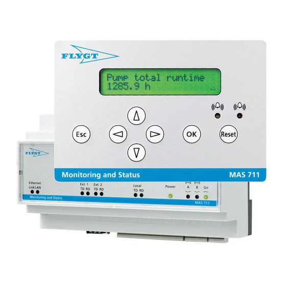
- MAS 711
- Installation and operation manual
-
Contents
-
Table of Contents
-
Troubleshooting
-
Bookmarks
Summary of Contents for FLYGT MAS 711
-
Page 1
Installation and Operation MAS 711 895115/10… -
Page 3: Table Of Contents
Warranty ………………….. 12 Warning Symbols ………………13 Product Description ………………. 15 System Components ………………16 Configurations………………..19 Monitoring Alternatives with ITT Flygt Pumps ……….20 Base Unit Indication………………21 Installation ………………….23 Installation Guideline ………………24 Connect the Unit ………………. 25 Connect to the Web Tool …………….
-
Page 4
Overview Settings with the Operator Panel …………….. 99 Change the Display Language …………..100 Log in and Change Password…………….101 Set Unit Information………………102 Retrieve Sensor Information from Pump Memory……….103 Make a Manual Setting of a Monitoring Channel ……….104 Record Running Time and Number of Starts ……….105 Check and Change the IP Address …………..107 Operation ………………….109 Handle Alarms ………………… -
Page 5
, Overview… -
Page 7: Preface
VIS10 Vibration sensor Reference More information about the MAS 711 and how to handle it is available in the following documents: • Technical specification, MAS 711 Monitoring system. • MAS Base unit, Modbus protocol (rev 1,2,3). • PAN 311/312 User manual.
-
Page 9: General Safety Information
• personal accidents and health problems • damage to the unit • product malfunction. ITT Flygt assumes no liability for either bodily injuries, material damages or economic losses beyond what is stated in this chapter. Table of This chapter contains the following topics:…
-
Page 10: Environment
General Safety Information, Environment Environment The unit must be installed in an environment that is • sheltered • well-ventilated, and • non-hazardous. Temperature The unit must be used at a temperature within the minimum and maximum rate defined in accompanying technical data. Disturbance Ensure that equipment causing serious disturbance is suppressed in the best possible way.
-
Page 11: User Safety And Health
General Safety Information, User Safety and Health User Safety and Health Introduction All government regulations, local health and safety directives must be observed. General All danger due to electricity must be avoided. Electrical connections must always be electricity carried out in compliance with the •…
-
Page 12: Warranty
Warranty Introduction ITT Flygt undertakes to remedy faults in products sold by ITT Flygt if the fault is • caused by defects in design, materials or workmanship, and • reported to ITT Flygt or ITT Flygt’s representative during the warranty period.
-
Page 13: Warning Symbols
General Safety Information, Warning Symbols Warning Symbols Symbols In the ITT Flygt documentation, admonitions are used together with the denomination. The following items describes the safety levels of the admonition symbols in combination with the denomination. DANGER! Risk of causing •…
-
Page 15: Product Description
Product Description Overview Table of This chapter contains the following topics: Contents Topic System Components ………………16 Configurations ………………..19 Monitoring Alternatives with ITT Flygt Pumps …………20 Base Unit Indication ………………. 21…
-
Page 16: System Components
Product Description , System Components System Components Illustration Component This table describes the system components: Description Number Component Description Operator panel Front panel mounted module used for interaction with the system. Base unit Contains a powerful processor, memory and terminals for sensor connections. Pump memory Mounted inside the pump and contains information about the pump.
-
Page 17
(update) of the pump memory with the latest information from the base unit takes place every second hour. Power MAS 711 is pre-programmed for use with the optional Power analyzer PAN311/PAN312. Analyzer See PAN 311/312 User manual for more information about setup and connection. -
Page 18
This communication port is dedicated for communication with a higher level system, System meaning for instance a Flygt APP/FMC pump controller or a PLC (Programmable Logical Controller). The base unit acts as a slave in such a network. A separate document (MAS Base unit, Modbus protocol) defines in detail how to set up the communication with the base unit and contains registers used for reading parameters. -
Page 19: Configurations
Product Description , Con fi gurations Configurations Configuration The system provides two alternative configurations useful for different situations: Alternatives • the base unit factory default configuration (for retrofit of CAS) or • a pump specific configuration brought by the pump memory. Default Since MAS might be used as sparepart for its predecessor CAS or for retrofit (upgrade), it is factory preset to fit as a CAS substitute.
-
Page 20: Monitoring Alternatives With Itt Flygt Pumps
Product Description , Monitoring Alternatives with ITT Flygt Pumps Monitoring Alternatives with ITT Flygt Pumps Large Pumps ITT Flygt standard monitoring (12-lead SubCab sensor cable) Large pumps are equipped with a standard set of monitoring sensors to allow safe and reliable operation.
-
Page 21: Base Unit Indication
Product Description , Base Unit Indication Base Unit Indication Illustration Light emitting diodes (LEDs) in the front are used for communication and relay indication. This is an illustration of the base unit LEDs: LED Indication This table describes what the base unit LEDs indicate: Description Num- Description…
-
Page 23: Installation
Installation Overview Table of This chapter contains the following topics: Contents Topic Installation Guideline ………………24 Connect the Unit ………………..25 General Instruction ………………26 Wiring, Supply and Additional Inputs/Outputs ……….28 Wiring, Modbus Communication …………..29 Wiring, Relay Outputs………………32 Wiring, Large Pumps, SubCab 12–lead Sensor Cable ……..
-
Page 24: Installation Guideline
Installation, Installation Guideline Installation Guideline Guideline This guideline gives an overview of the installation procedure. All steps are described in detail in the separate sections in the Installation chapter. This guideline only serves as an outline. Follow these steps to make a complete installation and setup: Step Action Read the entire chapter General Safety Information .
-
Page 25: Connect The Unit
Installation, Connect the Unit Connect the Unit Topics in this This section contains the following topics: Section • General Instruction • Wiring, Supply and Additional Inputs/Outputs • Wiring, Modbus Communication • Wiring, Relay Outputs • Wiring, Large Pumps, SubCab 12–lead Sensor Cable •…
-
Page 26: General Instruction
Installation, General Instruction Base Unit Terminal Block Terminal block section description This table describes the main sections of the base unit terminal block: Section Description number Supply and additional inputs/outputs Sensor terminals Ethernet port (RJ–45) Serial port (RS–232) Modbus communication (RS–485) Relay outputs General Instruction…
-
Page 27
Installation, General Instruction Main Parts when Connecting the Unit Description This table describes the main parts when connecting the unit: Section Description number Base unit terminal block Cabinet cables Cabinet connection block Sensor cable… -
Page 28: Wiring, Supply And Additional Inputs/Outputs
Installation, Wiring, Supply and Additional Inputs/Outputs Wiring Use the following wiring diagrams when connecting the unit: diagrams • The wiring diagram of the cabinet. • The applicable Wiring sections below. Instruction Follow the steps below to connect the unit: Step Action Check which number on the cabinet connection block that is connected to which number on the base unit terminal block.
-
Page 29: Wiring, Modbus Communication
Installation, Wiring, Modbus Communication Terminal This table describes the terminals for supply and additional inputs/outputs: Description Terminal Type Description number Configurable output, 4-20 mA Ground Configurable output, ground Reset input Ground RUN/reset, common ground RUN input Supply, 24 V AC/DC –/ground Supply, ground Wiring, Modbus Communication…
-
Page 30
Installation, Wiring, Modbus Communication P o w er L o ca l R ela y m o d u le M R M 0 1 Base Unit This table describes the Modbus communication terminals (RS-485) of the base unit: Terminal Terminal Type Description… -
Page 31
Installation, Wiring, Modbus Communication Pump Memory This table describes the pump memory terminals: Terminal Terminal Type Description Description number Local, B RS-485 (Modbus slave) Local, A RS-485 (Modbus slave) Ground Supply, ground Supply, 12 V DC Operator This table describes the operator panel terminals: Panel Terminal Terminal Type… -
Page 32: Wiring, Relay Outputs
Installation, Wiring, Relay Outputs Wiring, Relay Outputs Illustration This is an illustration of section 6 of the base unit terminal block: Terminal This table describes the terminals for the relay outputs: Description Terminal Description number Go relay (pump interlock), 5A/250V AC. Normally open. Go relay (pump interlock), 5A/250V AC.
-
Page 33
Installation, Wiring, Large Pumps, SubCab 12–lead Sensor Cable Wire This table shows the connection of the wires for a SubCab 12-lead sensor cable: Connection Sensor/Component Sensor cable, no. Base unit terminal block, no. FLS — Leakage in stator housing Pt100 — Temperature measurement, main bearing Thermal switches —… -
Page 34
Installation, Wiring, Large Pumps, SubCab 12–lead Sensor Cable Terminal This is a wiring diagram of the sensor terminals (section 2) used for a SubCab 12-lead Diagram sensor cable: Terminal This table describes the sensor terminals (section 2) used for a SubCab 12-lead sensor Description cable: Terminal… -
Page 35: Wiring, Large Pumps, Subcab 24-Lead Sensor Cable
Installation, Wiring, Large Pumps, SubCab 24–lead Sensor Cable Wiring, Large Pumps, SubCab 24–lead Sensor Cable NOTE! The wires of the sensor cable shall be connected to the cabinet connection block. The numbers of the cabinet connection block will differ from the numbers of the base unit terminal block.
-
Page 36
Installation, Wiring, Large Pumps, SubCab 24–lead Sensor Cable NOTE! FLS means either of leakage sensors FLS/FLS10/FLS20/FLS30 depending on type of pump. Communication port 37-38 for RS-485 is common to both pump memory and operator panel. Terminal This is a wiring diagram of the sensor terminals (section 2) used for a SubCab 24-lead Diagram sensor cable: VIS 10… -
Page 37: Wiring, Midrange Pumps, Subcab 12-Lead Sensor Cable, Alternative 1
Installation, Wiring, Midrange Pumps, SubCab 12–lead Sen- sor Cable, Alternative 1 Terminal Type Description Number Ground Temp measurement stator winding ph 2/ph 3, common ground Temp measurement, stator winding ph 3, Pt100 Temp measurement, stator winding ph 2, Pt100 Ground Temp measurement main bearing/stator winding ph 1, common ground Temp measurement, stator winding ph 1, Pt100…
-
Page 38
Installation, Wiring, Midrange Pumps, SubCab 12–lead Sensor Cable, Alternative 1 Sensor/Component Sensor cable, no. Base unit terminal block, no. • Supply, 12V + If applicable, attach screen to ground (Screen) terminals in the • pump top and • electrical cabinet. NOTE! If the sensor cable contains a green-yellow lead, that lead should not be connected. -
Page 39: Wiring, Midrange Pumps, Subcab 12-Lead Sensor Cable, Alternative 2
Installation, Wiring, Midrange Pumps, SubCab 12–lead Sen- sor Cable, Alternative 2 Terminal Type Description Number Ground Pump current transformer input, ground Pump current transformer input 1A AC Not used Not used Temp measurement, main bearing, Pt100 Not used Not used Not used Ground Temp measurement main bearing/stator winding ph 1,…
-
Page 40
Installation, Wiring, Midrange Pumps, SubCab 12–lead Sensor Cable, Alternative 2 Sensor/Component Sensor cable, no. Base unit terminal block, no. • Supply, ground • Supply, 12V + If applicable, attach screen to ground (Screen) terminals in the • pump top and •… -
Page 41: Wiring, Midrange Pumps, 25-Lead Sensor Cable
Installation, Wiring, Midrange Pumps, 25–lead Sensor Cable Terminal Type Description Number Not used Not used Not used Ground Pump current transformer input, ground Pump current transformer input 1A AC Not used Not used Temp measurement, main bearing, Pt100 Not used Not used Not used Ground…
-
Page 42
Installation, Wiring, Midrange Pumps, 25–lead Sensor Cable Sensor/Component Sensor cable, no. Base unit terminal block, no. Pump memory: • RS–485 B • RS-485 A • Supply, ground • Supply, 12V + Pt100 — Temperature measurement, stator winding ph 2 Pt100 — Temperature measurement, stator winding ph 3 Pt100 —… -
Page 43
Installation, Wiring, Midrange Pumps, 25–lead Sensor Cable Terminal This table describes the sensor terminals (section 2) used for a 25–lead sensor cable: Description Terminal Type Description Number Ground Vibration or optional sensor input, ground Vibration or optional sensor input, 4-20 mA Leakage in inspection chamber, FLS Ground Leakage in inspection chamber/junction box, common ground… -
Page 44: Connect To The Web Tool
Installation, Connect to the Web Tool Connect to the Web Tool Topics in this This section contains the following topics: Section • General Instruction • Make a Direct Connection • Make a LAN Connection • Make a Modem Connection General Instruction Instruction Follow the steps below to connect to the web tool: Step…
-
Page 45
Installation, Make a Direct Connection Step Action Comment/Result Click Start — Control panel and double click Network connections — Local area connection (name). Click Properties. Select Internet Protocol (TCP/IP) in the list and click Properties. If the option Use the following IP address is used, write down the existing IP address (to be able to restore the IP settings of your… -
Page 46: Make A Lan Connection
Installation, Make a LAN Connection Step Action Comment/Result • Start a web browser (for example Internet Explorer). • Enter the IP address of the unit (default is http://10.0.48.94) in the address field and click Enter. Click Login. The Login dialog box is opened. Enter user name (config) and The web tool Quick overview is opened.
-
Page 47
Installation, Make a LAN Connection 1. Contact a local network administrator to check if the IP address and additional ethernet settings of the base unit have to be changed before connecting to an existing LAN. If the base unit IP address •… -
Page 48
Installation, Make a LAN Connection • Click Properties. • Select Internet Protocol (TCP/IP) and click Properties in the Local Area Connection Properties dialog box. Result: The Internet Protocol (TCP/IP) Properties dialog box is opened. • Tick Use the following IP address and enter the computer address in the IP address field. -
Page 49
Installation, Make a LAN Connection • Change all positions to form the desired IP address. • Press OK and confirm with OK. Result:”Value saved” is displayed briefly. Comment: Period (.) is found after number 9 and space ( ) before number 0. •… -
Page 50: Make A Modem Connection
Installation, Make a Modem Connection Make a Modem Connection Instruction Instruction Follow these steps to make a modem connection between a computer and the base unit: Step Action Comment/Result • Connect a modem (PSTN, GSM or GPRS) to the base unit using a cable with RS-232, 9-pole Dsub connectors.
-
Page 51
Installation, Make a Modem Connection Step Action Comment/Result • Start a web browser. • Enter the IP address of the unit (default is http://192.168.48.95) in the address field and click Enter. Click Login. The Login dialog box is opened. Enter user name (config) and The web tool Quick overview is password (default is ef56) in the login opened. -
Page 52: First Setup Using The Web Tool
Pump memory, Operator (RS-485, Modbus) panel, Relay Module, Power analyzer, Higher level controller (Flygt APP/FMC or PLC). If there is • a pump memory in the system, continue with step 6. • no pump memory in the system (for example for retrofit of a CAS), continue with step 7.
-
Page 53
Installation, First Setup Using the Web Tool Step Action Detailed instruction in chapter Settings with the Web Tool Use one of the following methods to enable recording of Record Running pump running time and number of starts: Time and Number •… -
Page 54
Installation, First Setup Using the Web Tool Step Action Detailed instruction in chapter Settings with the Web Tool Click (Setup — Pump Info — ) Service interval if you Handle Pump want to make changes to the service intervals. Information and Service Functions Using the Web Tool (in chapter… -
Page 55: First Setup Using The Operator Panel
Installation, First Setup Using the Operator Panel First Setup Using the Operator Panel Instruction When setting up using the operator panel, use the operator panel • menu system (see chapter Use the Operator Panel ) and • menu navigation help. Follow these steps to set up using the operator panel.
-
Page 56
Installation, First Setup Using the Operator Panel Step Action Detailed instruction in chapter Settings with the Operator Panel If the pump is installed in an explosive or flammable Make a Manual environment, make sure that the motor overheating Setting of a protection function (Temp stator ph 1-3) is setup to stop the Monitoring pump, that is, an A-alarm. -
Page 57: Use The Web Tool
Use the Web Tool Web Tool Illustration Window This illustration shows the web tool window. Window Description This table describes the main sections of the web tool window: Number Description Mode selection, View or Setup General information: Pump station name and address, pump type and serial number Alarm indication (A or B level) Function selection (Quick overview in View mode in this example)
-
Page 58
Use the Web Tool, Overview Access Levels There are two access levels determining the scope of possible actions for the user. Access and Default level is determined at login and is entered as User name. • User name Config gives access to all setting and viewing possibilities. Password •… -
Page 59: Use The Operator Panel
Use the Operator Panel Overview Table of This chapter contains the following topics: Contents Topic Browse the Menus ………………… 60 Menu System………………… 63…
-
Page 60: Browse The Menus
Use the Operator Panel, Browse the Menus Browse the Menus Operator Panel Illustration This is an illustration of the operator panel: Panel description This table gives an overview of the main parts of the operator panel: Part Name Description Menu navigation Used to navigate through the menu system.
-
Page 61
Use the Operator Panel, Browse the Menus If you want to … then press … • advance one menu or • decrease a value or • advance among a set of alternative parameters • move backwards one menu or • increase a value or •… -
Page 62
Use the Operator Panel, Browse the Menus When an Alarm is Detected When an alarm condition is detected the display shows the event log, which is a list of present and previous alarms and events. -
Page 63: Menu System
Use the Operator Panel, Menu System Menu System Setup and The main menu structure is divided into two major branches, Setup and View, in analogy View with the operating modes of the web tool. Navigation A menu navigation help can be activated from the Setup menu. Whenever a button is Help pressed, the menu number is displayed briefly in the display, showing the present position in the menu system (see below).
-
Page 64
Use the Operator Panel, Menu System Menu Menu name/Description number Pump start recording no. 1 (date and time) → Pump stop recording 1.5.1 no. 1 (date and time) ↓ Pump start last recording → Pump stop last recording (max 50) 1.5.50 Temp stator ph 1-3 (Status) (Thermal switch/Thermistor ohm reading) 1.6.1… -
Page 65
Use the Operator Panel, Menu System Menu Menu name/Description number 1.17 Pump current Same menu structure as Temp stator ph 1 1.18 Power analyzer channel 1 — Reading Same menu structure as Temp stator ph 1 1.19 Power analyzer channel 2 — Reading Same menu structure as Temp stator ph 1 1.20 Power analyzer channel 3 — Reading… -
Page 66
Use the Operator Panel, Menu System Menu Menu name/Description number Menu navigation 2.2.1 Active/Inactive Login 2.3.1 Enter code (default is 1234). The following menus (2.4 — 2.23) require correct password code. Change password 2.4.1 Enter new code using arrow keys. General config 2.5.1 Clock… -
Page 67
Use the Operator Panel, Menu System Menu Menu name/Description number 2.5.9 Power analyzer baudrate 2.5.9.1 19200/9600 baud 2.5.10 Power analyzer Id 2.5.10.1 Setting: 1-255 2.5.11 Power analyzer type 2.5.11.1 PAN 311/PAN312/WM14 (Ext 2) 2.5.11.2 WM22 (Ext 2) 2.5.12 Higher level ctrl (controller) (Ext 1) 2.5.12.1 Active/Inactive 2.5.13… -
Page 68
Use the Operator Panel, Menu System Menu Menu name/Description number 2.6.2 Alarm limits 2.6.2.2 Very high (R > 750 ohm)/Very high (R > 3000 ohm) 2.6.2.6 Short circuit (R < 20 ohm) 2.6.3 Alarm action priority 2.6.3.2 Very high (Warning/Pump stop/Off) 2.6.3.6 Short circuit (Warning/Pump stop/Off) 2.6.4… -
Page 69
Use the Operator Panel, Menu System Menu Menu name/Description number Temp stator ph 2 Same structure as for Temp stator ph1 (2.7) above Temp stator ph 3 Same structure as for Temp stator ph1 (2.7) above 2.10 Temp main bearing Same structure as for Temp stator ph1 (2.7) above 2.11 Temp support bearing… -
Page 70
Use the Operator Panel, Menu System Menu Menu name/Description number 2.13.4.1 Short circuit (Manual/Automatic) 2.13.4.2 Leakage (Manual/Automatic) 2.13.4.6 Broken circuit (Manual/Automatic) 2.13.5 Alarm delay 2.13.5.1 Short circuit (0 — 30s) 2.13.5.2 Leakage (0 — 30s) 2.13.5.6 Broken circuit (0 – 30s) 2.14 Leakage junction box Same structure as for Leakage stator housing (2.13) above… -
Page 71
Use the Operator Panel, Menu System Menu Menu name/Description number 2.16.4.1 Short circuit (Manual/Automatic) 2.16.4.2 Very high (Manual/Automatic) 2.16.4.3 High (Manual/Automatic) 2.16.4.4 Low (Manual/Automatic) 2.16.4.5 Very low(Manual/Automatic) 2.16.4.6 Broken circuit (Manual/Automatic) 2.16.5 Alarm delay 2.16.5.1 Short circuit (0 — 30s) 2.16.5.2 Very high (0 — 30s) 2.16.5.3… -
Page 72
Use the Operator Panel, Menu System Menu Menu name/Description number 2.17.4.4 Low (Manual/Automatic) 2.17.4.5 Very low (Manual/Automatic) 2.17.5 Alarm delay 2.17.5.2 Very high (0-30 s) 2.17.5.3 High (0-30 s) 2.17.5.4 Low (0-30 s) 2.17.5.5 Very low (0-30 s) 2.17.7 Transformer rating (primary current) 2.18 System power 2.18.1… -
Page 73
Use the Operator Panel, Menu System Menu Menu name/Description number 2.19.2 Alarm limits 2.19.2.2 Very high (P > x kW) 2.19.2.2.1 Setting of alarm limit 2.19.2.3 High (P > y kW) 2.19.2.3.1 Setting of alarm limit 2.19.3 Alarm action priority 2.19.3.2 Very high (Warning/Pump stop/Off) 2.19.3.3… -
Page 74
Use the Operator Panel, Menu System Part of Only a very limited part of the Setup menu is available without login. In the following Setup Menu description, the menu numbers refer to the position in the menu system. Available This table shows the part of the Setup menu system that is available without login: Without Login Menu Menu name… -
Page 75
Settings with the Web Tool Overview Table of This chapter contains the following topics: Contents Topic Change Password ………………… 76 Change the Display Language …………….77 Set Unit Information……………….. 79 Configure Communication (RS-485, Modbus) …………. 80 Make a Manual Setting of a Monitoring Channel ……….82 Record Running Time and Number of Starts ………… -
Page 76: Settings With The Web Tool
Settings with the Web Tool, Change Password Change Password Instruction Follow these steps to change the password: 1. Log in at access level config (user name: config, default password: ef56). Comment: It is also possible to set the password for the operator panel (can also be done from the operator panel menu system).
-
Page 77: Change The Display Language
Settings with the Web Tool, Change the Display Language Change the Display Language Web tool Illustration menus This is an illustration of the web tool menus used in the instruction below: Menu Description This table describes the web tool menus used in the instruction below: Menu number Name Setup…
-
Page 78
Settings with the Web Tool, Change the Display Language Instruction Follow these steps to change the display language: Step Action Click Setup (right tab of the side menu) – General configuration (menu option at the bottom of the side menu). Click General settings (top menu option in the middle column of the centre menu). -
Page 79: Set Unit Information
Settings with the Web Tool, Set Unit Information Set Unit Information Instruction Follow these steps to set the time and temperature unit and enter pump station information (visible at the top of the web pages): 1. Click Setup – General configuration – Unit information. Result: The Unit information window is opened.
-
Page 80: Configure Communication (Rs-485, Modbus)
Settings with the Web Tool, Con fi gure Communication (RS-485, Modbus) Configure Communication (RS-485, Modbus) Instruction Follow these steps to switch the RS-485/Modbus communication on and off and to configure the communication: 1. Click Setup — General configuration — RS-485/Modbus. Result: The RS–485/Modbus communication window is opened.
-
Page 81
Settings with the Web Tool, Con fi gure Communication (RS-485, Modbus) 5. Higher level controller Contact your local service organization if you want to set up communication with a higher level controller (APP/FMC/PLC). Comment: The protocol (Modbus) used for communication over port Ext 1 to a Higher level controller (central system) has been upgraded to revision 3. -
Page 82: Make A Manual Setting Of A Monitoring Channel
Settings with the Web Tool, Make a Manual Setting of a Monitoring Channel Make a Manual Setting of a Monitoring Channel Instruction Follow these steps to activate and make a manual setting of a channel (Temp stator ph 1 is an example): •…
-
Page 83
Settings with the Web Tool, Make a Manual Setting of a Monitoring Channel Reference: See section Compensate for Measurement Error due to Long Leads . 7. Click Update. -
Page 84: Record Running Time And Number Of Starts
Settings with the Web Tool, Record Running Time and Number of Starts Record Running Time and Number of Starts Conditions for Running time and number of starts are registered provided that either of the following Recording conditions is fulfilled: • Pump current is measured by means of a current transformer connected to terminals 11-12 or •…
-
Page 85
Settings with the Web Tool, Record Running Time and Number of Starts • Set the alarm limits manually or automatically. To set up the limits automatically, tick Automatic setup of alarm limits and graph settings at Update. This will set the alarm limits according to the data plate information. -
Page 86: Compensate For Measurement Error Due To Long Leads
Settings with the Web Tool, Compensate for Measurement Error due to Long Leads Compensate for Measurement Error due to Long Leads Wire A Pt100 sensor changes resistance with temperature and thus the base unit can measure Resistance the resistance to calculate the temperature. The wiring from the system to the sensor and back adds resistance to the measurement and causes an error —…
-
Page 87
Settings with the Web Tool, Compensate for Measurement Er- ror due to Long Leads Lead Illustration Resistance This is an illustration of the lead resistance measurement method: Measurement Method Pt100 lead Measurement tools This table describes the main tools in the lead resistance measurement: Number Description Multimeter. -
Page 88
Settings with the Web Tool, Compensate for Measurement Error due to Long Leads Measure and compensate Follow these steps to measure the resistance and compensate for measurement error due to long leads: 1. Measure the resistance by putting a jumper close to the Pt100 sensor to short circuit, and measure the lead resistance, r , from the MAS end. -
Page 89
Settings with the Web Tool, Compensate for Measurement Er- ror due to Long Leads Calculate automatically and compensate Follow these steps to calculate the resistance automatically and compensate for measurement error due to long leads: 1. Calculate the resistance automatically by entering the resistivity, cable length and cross section area into the Calculation help field (in Setup –… -
Page 90: Update The Internal Program
When using this file all parts of the software will be correctly updated to the latest version. Note! Contact your local Flygt representative to obtain the latest upgrade file. The file is typically named: MAS_A_upgrade_F224_W224_B220_071004.exe File name description…
-
Page 91
Settings with the Web Tool, Update the Internal Program Step Action Result Run the update program by double-clicking it. Follow the instruction in the program: During the upgrade progress messages are displayed in the message field on • Make sure the unit is connected and online. -
Page 92: Set Reload Time For Alarm And Quick Overview
Settings with the Web Tool, Set Reload Time for Alarm and Quick Overview Set Reload Time for Alarm and Quick Overview Instruction Follow these steps to set alarm and quick overview reload time: Action Step Click Setup — General configuration — General settings. Select desired reload time (interval to update measurement results and alarms presented on the Quick overview and Alarm and event log pages).
-
Page 93: Make Settings For Alarm Distribution Through E-Mail
Settings with the Web Tool, Make Settings for Alarm Distribution through E-mail Make Settings for Alarm Distribution through E-mail Instruction Parameters for alarm distribution through email can be set. Follow these steps to set up the email communication: 1. Click Setup – General configuration – Email settings. Result: The Email settings window is opened.
-
Page 94: Make Modem/Ppp Settings
Settings with the Web Tool, Make Modem/PPP Settings Make Modem/PPP Settings Purpose The modem/PPP settings are used for direct connection between the computer and the base unit using modem and PPP (point-to-point protocol). The settings must be done for the unit to initiate a dial up connection, which is needed for the alarm distribution through email to work when connected via a dial up modem connection.
-
Page 95
Settings with the Web Tool, Make Modem/PPP Settings • Click Update and then Restart to use the updated settings. 4. Click (Setup – General configuration –) Ethernet. • Set the gateway to 0.0.0.0. • Click Update and then Restart to use the updated settings. •… -
Page 96: Set Up Mas Network Overview
Settings with the Web Tool, Set Up MAS Network Overview Set Up MAS Network Overview Instruction MAS network overview displays key data and alarm status from other units connected to the same network. Follow these steps to set up the MAS network overview: 1.
-
Page 97: Set Up Mas Relay Module
Settings with the Web Tool, Set Up MAS Relay Module Set Up MAS Relay Module Instruction MRM 01 is an optional output unit containing four relays. It enables communication for individual monitoring channel alarms (A and/or B alarms) to specific relays and LEDs on the relay module(s).
-
Page 99: Settings With The Operator Panel
Settings with the Operator Panel Overview Table of This chapter contains the following topics: Contents Topic Change the Display Language …………….100 Log in and Change Password …………….101 Set Unit Information……………….102 Retrieve Sensor Information from Pump Memory ……….103 Make a Manual Setting of a Monitoring Channel ……….104 Record Running Time and Number of Starts …………105 Check and Change the IP Address…………..107…
-
Page 100: Change The Display Language
Settings with the Operator Panel, Change the Display Language Change the Display Language Instruction Follow these steps to change the display language: Action Result Step • Press Esc a number of times to Menu Language (2.1) is opened and go to the main menu. the present language is displayed.
-
Page 101: Log In And Change Password
Settings with the Operator Panel, Log in and Change Password Log in and Change Password Log in Without logging in the entire View menu but only a part of the Setup menu is accessible. To access the rest of the Setup menu you have to log in using a password. Follow these steps to log in: Step Action…
-
Page 102: Set Unit Information
Settings with the Operator Panel, Set Unit Information Set Unit Information Instruction Follow these steps to set unit information: Action Result Step The text is flashing. • Go to General config (2.5) in the Setup menu using up/down arrow. • Press OK to enter menu Clock (2.5.1). •…
-
Page 103: Retrieve Sensor Information From Pump Memory
Settings with the Operator Panel, Retrieve Sensor Information from Pump Memory Retrieve Sensor Information from Pump Memory Instruction Follow these steps to retrieve sensor information from the pump memory: Action Result Step The text is flashing. • Go to General config (2.5) in the Setup menu using up/down arrow.
-
Page 104: Make A Manual Setting Of A Monitoring Channel
Settings with the Operator Panel, Make a Manual Setting of a Monitoring Channel Make a Manual Setting of a Monitoring Channel Reasons There are two reasons for making manual/additional settings to monitoring channels: for Making • There is no pump memory. You want to complete the following 4 default channels with additional channels or/and adjust a setting for these channels: Settings –…
-
Page 105: Record Running Time And Number Of Starts
Settings with the Operator Panel, Record Running Time and Number of Starts Record Running Time and Number of Starts Conditions for Running time and number of starts are registered provided that either of the following Recording conditions is fulfilled: • Pump current is measured by means of a current transformer connected to terminals 11-12 or •…
-
Page 106
Settings with the Operator Panel, Record Running Time and Number of Starts Step Action Current (power analyzer) • Make additional settings to the channel. See section Make a Manual Setting of a Monitoring Channel . • Activate and set the following channels: —… -
Page 107: Check And Change The Ip Address
Settings with the Operator Panel, Check and Change the IP Address Check and Change the IP Address Instruction Follow these steps to check and change the IP address: Action Result Step • Go to menu Ethernet IP address (2.5.16) in the Setup menu using up/down arrow.
-
Page 109: Operation
Operation Overview Table of This chapter contains the following topics: Contents Topic Handle Alarms ………………..110 General Information………………110 Alarm Indication and Listing …………….. 110 Analyze and Acknowledge Alarms Using the Web Tool ……..112 View and Acknowledge Alarms Using the Operator Panel ……113 View Operation Data ………………
-
Page 110: Handle Alarms
Operation, Handle Alarms Handle Alarms Topics in this This section contains the following topics: Section • General Information • Alarm Indication and Listing • Analyze and Acknowledge Alarms Using the Web Tool • View and Acknowledge Alarms Using the Operator Panel General Information Two Alarm Alarms are generated when an abnormal condition occurs, either associated with the…
-
Page 111
Operation, Alarm Indication and Listing Alarm This table shows where and how the alarms are indicated: Indication The alarms are indicated … on the … • with LEDs and operator panel. • as text on the display with LEDs base unit front. as colored fields (yellow and red) at the top web tool. -
Page 112: Analyze And Acknowledge Alarms Using The Web Tool
Operation, Analyze and Acknowledge Alarms Using the Web Tool Analyze and Acknowledge Alarms Using the Web Tool The alarm status is displayed with the A and B icons in the blue field at the top of the Alarm Status Indication and web pages.
-
Page 113: View And Acknowledge Alarms Using The Operator Panel
Operation, View and Acknowledge Alarms Using the Operator Panel View and Follow these steps to view and analyze an alarm: Analyze Step Action Alarms If an alarm is active (displayed by the alarm status icons, A and B), click • the icons or •…
-
Page 114
Operation, View and Acknowledge Alarms Using the Operator Panel Appearance of Reason for the condition Action the alarm LEDs Flashing red 1. An alarm is presently 1. Press Reset to active and not acknowledge the alarm. acknowledged or Result: The LED turns solid red. -
Page 115: View Operation Data
Operation, View Operation Data View Operation Data Topics in this This section contains the following topics: Section • General Information • View Operation Data Using the Web Tool • View Operation Data Using the Operator Panel General Information MAS is able to present data both with figures and diagrams. Momentary data, max and Introduction min values and recordings over a long time period can be viewed.
-
Page 116: View Operation Data Using The Web Tool
Operation, View Operation Data Using the Web Tool View Operation Data Using the Web Tool Available The table shows the available information menus on the main (left) menu: Information Function Description/Sub menu Menus MAS network overview Displays key data and alarm status from other MAS units connected to the same network.
-
Page 117
Operation, View Operation Data Using the Web Tool 2. If desired, click Reset min/max to make a quick reset of all min and max values. Individual reset is possible on the separate windows for each channel. Reference: See section View Monitoring Channels on how to view additional status and measurement information. -
Page 118
Operation, View Operation Data Using the Web Tool Produce and Follow these steps to produce a chart: View a Chart 1. Click View – Trend diagrams. Result: The Trend diagrams window is opened. 2. Select up to three channels to plot in the same chart versus three separate axes in the drop-down menus of the Monitored channel field. -
Page 119
Operation, View Operation Data Using the Web Tool View the Alarm The Alarm and event plot is used to study the course of events leading up to and and Event Plot surrounding an alarm. Follow these steps to view the Alarm and event plot: 1. -
Page 120
Operation, View Operation Data Using the Web Tool View Running Introduction Statistics Running statistics consist of • histogram data • start and stop registrations. This data is saved both in the base unit and in the pump memory. The base unit copies data to the pump memory every two hours. -
Page 121
Operation, View Operation Data Using the Web Tool View Follow these steps to view monitoring channels: Monitoring 1. Click View – Temp stator ph 1 (example). Channels Result: • The present measurement value and status for the channel is displayed. •… -
Page 122
Operation, View Operation Data Using the Web Tool • Click Data plate to view data plate information containing pump identity, electrical data etc • Click Service log to view the operator’s own service notes • Click Service interval to view information on when the next service will be prompted according to the operator’s own settings. -
Page 123: View Operation Data Using The Operator Panel
Operation, View Operation Data Using the Operator Panel Result: A new browser is opened. View Operation Data Using the Operator Panel View Status Follow these steps to view status, measurement reading and min and max reading for a and Readings monitoring channel: for a Channel Step Action…
-
Page 124
Operation, View Operation Data Using the Operator Panel Step Action Result • Press OK to reset the present trip • “Wait” is displayed briefly, then back counter. to menu Pump counter runtime • Confirm with OK. (1.3.1). • The trip counter is now reset and the previous value is saved in a list of the 10 last trip counters. -
Page 125
Operation, View Operation Data Using the Operator Panel View Status Follow these steps to view status on digital I/O ports: on Digital I/O Step Action Ports Go to menu Digital I/O ports (1.23) using down arrow. Press OK to go to the first digital I/O channel, Run input (1.23.1), and to view its present status (On/Off). -
Page 126: Handle Database Information And Parameters
Operation, Handle Database Information and Parameters Handle Database Information and Parameters Topics in this This section contains the following topics: Section • Backup and Restore Parameters • Preserve, Upload and Delete Measurement Data Backup and Restore Parameters Parameter Parameter means all sorts of settings used internally by the program. Parameters may Definition control the program logic, contain running data or simply text.
-
Page 127
Operation, Backup and Restore Parameters 2. In the Download user settings field, click Download file to the right of the text “Backup all user settings, Running statistics, Service log, Data plate, etc”. 3. Create a directory and save the file Backup.par. Note! It is recommended to give the file a specific name. -
Page 128
Operation, Backup and Restore Parameters 2. Enter IP address, User name and Password in the MAS Update dialog box. • Click the browse button (…) to the right of the Filename field and select the backup(.par) file. • Select Backup and click Upload. Restore parameters using the Backup-Update function Follow these steps to restore parameters from a backup file using the Backup-Update function:… -
Page 129
Operation, Backup and Restore Parameters Result: “Update in progress” is displayed above the Update window. The message “Update OK!” confirms that the update is completed. Change and Follow these steps to change and load selected parameters into the base unit: Load Selected Action Step… -
Page 130: Preserve, Upload And Delete Measurement Data
Operation, Preserve, Upload and Delete Measurement Data 7. Click Setup — Pump info — Pump memory. 8. In the Manual pump memory synchronization field, select Copy all from MAS to pump memory and click Copy. Result: ”Do you want to perform the synchronization?” is displayed. 9.
-
Page 131
Operation, Preserve, Upload and Delete Measurement Data Preserve All There are two methods for saving all measurement data in a system: Measurement • Save all measurement data to be viewed in (for example) Excel. • Save all measurement data to be restored into the system. Data in a System Note! If you want to make a complete backup of the system, the parameters also have to… -
Page 132
Operation, Preserve, Upload and Delete Measurement Data • Select Backup all logged data in the Download data log field. • Click Download file. Result: The database(.bin) file can now be restored into a base unit. -
Page 133
Operation, Preserve, Upload and Delete Measurement Data Upload All Follow these steps to upload all measurement data: Measurement 1. Click Setup – General configuration – Program update. Data to a Result: The MAS update dialog box is opened. System 2. Enter IP address, User name and Password in the MAS update dialog box. •… -
Page 134
Operation, Preserve, Upload and Delete Measurement Data Delete All Follow these steps to delete all measurement data in a system: Measurement 1. Click Setup – Data log. Data in a System • Select All in the Select data log drop-down menu and click Clear. •… -
Page 135: Handle Pump Information And Service Functions
Operation, Handle Pump Information and Service Functions Handle Pump Information and Service Functions Topics in this This section contains the following topics: Section • Handle Pump Information and Service Functions Using the Web Tool • Set Service Interval Using the Operator Panel Handle Pump Information and Service Functions Using the Web Tool The data plate has one fixed part (original factory information) and one editable part.
-
Page 136
Operation, Handle Pump Information and Service Functions Using the Web Tool 4. If you want to copy the changes immediately, see section Copy Data To/From Pump Memory . Make an Entry It is possible to make own service notes and store them in the base unit and pump memory. in the Service Follow these steps to make an entry in the service log: 1. -
Page 137: Set Service Interval Using The Operator Panel
Operation, Set Service Interval Using the Operator Panel Set Service Service will be prompted according to the operator’s own settings based on running time, number of starts or a fixed date. Interval Follow these steps to set the service interval: 1.
-
Page 138
Operation, Set Service Interval Using the Operator Panel Step Action Result/Comment Press OK to enter the settings menu. Menu Service every (example: 2.5.2.1.1) is displayed together with the present setting. Press OK to enter edit mode and set the interval of the service message. •… -
Page 139: Copy Data To/From Pump Memory
Operation, Copy Data To/From Pump Memory Copy Data To/From Pump Memory Topics in this This section contains the following topics: Section • Copy Data To/From Pump Memory Using the Web Tool • Copy Data To/From Pump Memory Using the Operator Panel Data Copied The following data is automatically copied from MAS to the pump memory every 2 hours: During Pump…
-
Page 140: Copy Data To/From Pump Memory Using The Operator Panel
Operation, Copy Data To/From Pump Memory Using the Operator Panel Step Action Result In the Manual pump memory synchronization “Do you want to perform the field, select Copy all from MAS to pump synchronization?” is displayed. memory and click Copy. Click OK.
-
Page 141
Operation, Copy Data To/From Pump Memory Using the Operator Panel Copy All Data It is possible to copy any recent changes or latest measurements immediately to the from MAS to pump memory, for example before service, to make sure the latest data is stored in the pump memory before removing the pump. -
Page 143: Trouble Shooting
Trouble Shooting Overview Table of This chapter contains the following topics: Contents Topic Common Problems and Solutions …………..144 Event Messages and Actions …………….146…
-
Page 144: Common Problems And Solutions
• It the default passwords are changed, make sure you have the new password. • Passwords are case sensitive. • If you lose your password, contact your local ITT Flygt organization. Can Not This table shows the indication of and solution for problems with connecting to the web tool:…
-
Page 145
• Check that the sensor is working by disconnecting the wires and measuring or by contacting your local ITT Flygt organization. • If the sensor will get its power supply from the MAS, measure the power supply. • Change the sensor… -
Page 146: Event Messages And Actions
No action (not active) Watchdog Software failure. Restart If the message recurs, reset initiated by software because contact your local ITT Flygt of internal error. organization. FLASH Error in database memory If the message recurs, csum/mr error contact your local ITT Flygt organization.
-
Page 147
Common Problems and Solutions . Pump mem. Pump memory error If the message recurs, csum error contact your local ITT Flygt organization. No pump Pump serial number in Base Synchronize Pump memory memory sync unit and Pump memory differ and MAS manually. -
Page 149: Contact Information
Distributor The distributor for our products in your area is found at www.flygt.com. Customer To get in contact with the ITT Flygt customer support please Support • call +46 (0)44 20 59 59 • fax +46 (0)44 20 59 01…
-
Page 150
Installation and Operation MAS 711 895115/10 — 20071212 www.flygt.com © ITT Flygt AB, Printed in Sweden…
Table of Contents for Xylem FLYGT MAS 711:
-
4 Mechanical Installation 4.1 Install the unit on a DIN rail WS009306A 1. Hook the lip at the back of the unit onto the top of the DIN rail. 2. Press the unit down until the rail clip snaps into place. 4 Mechanical Installation 10 MAS 711 Installation, Operation, and Maintenance Manual
-
WS009587A 2. Select the All in the Select data log drop-down menu. 3. Click Download file. The database.dta file can now be viewed in Microsoft Excel ® . 7.2.15 Save all the measurement data to restore the system 1. Click Setup > General configuration > Backup. WS009588A 2. Click Download file to the right of Backup all logged data. The database.bin file can now be restored into a base unit. 7.2.16 Upload all the measurement data to a system 1. Click Setup > General configuration > Program update. 7 Operati
-
4. If a portable operator panel is used for a temporary connection, then turn off the operator panel communication alarm for the base unit. 5. Select the type of Power analyzer from the drop-down menu. 6. Set the Baudrate and Modbus Address to allow communication between the power analyzer and the base unit. The default Baudrate is 9600 and default Address is 255. If no changes are made to the default settings in the power analyzer, then these d
-
1 Introduction and Safety 1.1 Introduction Purpose of the manual The purpose of this manual is to provide necessary information for installation, operation, and maintenance of the unit. Read and keep the manual Save this manual for future reference, and keep it readily available at the location of the unit. CAUTION: Read this manual carefully before installing and using the product. Improper use of the product can cause personal inj
-
7 Operation 7.1 Alarm levels and handling For most monitoring channels, the base unit uses two levels of alarms, A, and B. These alarm levels are available in the Setup mode: Alarm level Description A It shows a serious condition. The Go interlock relay opens to stop the pump, the A alarm relay switches and the indications light up red. B It shows a less serious condition or is used as a warning level. The pump continues to run, the B al
-
10 Technical Reference 10.1 Dimensions WS009780A 1 2 3 4 Base unit 1. 60 mm (2.4 in) 2. 115 mm (4.5 in) 3. 86 mm (3.4 in) 4. 156 mm (6.14 in) 1 2 3 4 5 6 7 8 WS009781A 9 10 11 12 13 14 Operator panel 1. 96 mm (3.8 in) 2. 5.5 mm (0.22 in) 3. 85 mm (3.3 in) 4. 144 mm (5.67 in) 5. 133 mm (5.24 in) 6. 5.5 mm (0.22 in) 7. 126 mm (4.96 in) 8. 9 mm (0.35 in) 9. 18 mm (0.71 in) 10.2.4 mm (0.09 in) 11.M3 12.78 mm (3.1 in) 10 Technical Referenc
-
Save value? appears. e) Press OK. Value saved! appears. 5. Select one of the steps: Condition Action The network consists of several subnets. Edit the IP address of the router in the Ethernet Gateway 2.15.18 menu. The network has no subnets. — 6. Restart the base unit. 6.7 Connect a computer to the web tool through a LAN Contact the local network administrator for the compliant settings. 1. Set the IP address of the base u
-
5.3 Connect the Modbus communication 39 40 41 42 Ext.2 8 9 10 11 74 75 76 77 — + B A 38 37 36 35 34 33 S R2 R3 R4 Loc al TD RD R1 Po wer Rela y mo dule MRM 01 12 11 12 13 7 14 15 PAN 311 PAN 312 WS009536A 12 11 7 8 9 10 11 7 PAN 311 PAN 312 1 2 3 4 5 1. Pump controller 2. Power analyzer 3. Pump memory 4. Operator panel 5. Relay module Connect the applicable units to the Modbus terminals. 5 Electrical Installation 16 MAS 711 Installation, Operation,
-
4. To reset the value press OK . Reset value? appears. 5. Press OK. Value reset! appears. 7.3.2 View the alarms 1. Go to the Event log 1.1 menu. 2. Press OK. The first row shows the latest channel that is affected. The second row shows the type of event. If there is more information about the event, then there is an arrow in the lower-right corner of the screen. 3. Select one of the steps: Condition Action View more information about the event. Press the right arrow button. T
-
5. Enter a maximum Email recipients. 6. Click Update. If the unit is connected through a dial-up modem connection, then changes to the modem settings must be made. For more information, see Set up a modem (page 30). 7. Click Send to test the email function. 6.8.11 Set up a modem These settings are used to connect directly to the computer and the base unit with the modem and point-to-point protocol (PPP). The setup must be done for the unit to start a dial-up connection. This function
Questions, Opinions and Exploitation Impressions:
You can ask a question, express your opinion or share our experience of Xylem FLYGT MAS 711 device using right now.
Download or browse on-line these Installation And Operation Manual for FLYGT MAS 711 Measuring Instruments.
Summary of Contents:
 |
[Page 1] FLYGT MAS 711 Installation and Operation MAS 711 895115/10 |
 |
[Page 2] FLYGT MAS 711 … |
 |
[Page 3] FLYGT MAS 711 Installation and Operation MAS 711 Overview 3 Table of Contents This publication contains the following topics: Topic Preface ………………………………………………………………………………………………… 7 General Sa… |
 |
[Page 4] FLYGT MAS 711 Overview Settings with the Operator Panel ………………………………………………………………. 99 Change the Display Language ……………………………………………………………. 100 Log in and Change Password….. |
 |
[Page 5] FLYGT MAS 711 , Overview 5 |
 |
[Page 6] FLYGT MAS 711 … |
 |
[Page 7] FLYGT MAS 711 Preface Purpose The purpose of this manual is to give the reader an overview of how to install and set up the MAS 711. Recipient The manual is principally intended for ITT Flygt • service departments and •customers. Product Documentation The poli… |
 |
[Page 8] FLYGT MAS 711 … |
 |
[Page 9] FLYGT MAS 711 General Safety Information Overview NOTE! It is extremely important that you read, understand and follow the warnings and safety regulations carefully before handling an ITT Flygt product. They are published to help prevent • personal accidents and… |
 |
[Page 10] FLYGT MAS 711 General Safety Information, Environment Environment The unit must be installed in an environment that is • sheltered • well-ventilated, and • non-hazardous. Temperature The unit must be used at a temperature within the minimum and maximum rate … |
 |
[Page 11] FLYGT MAS 711 General Safety Information, User Safety and Health User Safety and Health Introduction All government regulations, local health and safety directives must be observed. General electricity precautions All danger due to electricity must be avoided. Ele… |
 |
[Page 12] FLYGT MAS 711 General Safety Information, Warranty Warranty Introduction ITT Flygt undertakes to remedy faults in products sold by ITT Flygt if the fault is • caused by defects in design, materials or workmanship, and • reported to ITT Flygt or ITT Flygt’s r… |
 |
[Page 13] FLYGT MAS 711 General Safety Information, Warning Symbols Warning Symbols Symbols In the ITT Flygt documentation, admonitions are used together with the denomination. The following items describes the safety levels of the admonition symbols in combination with the… |
 |
[Page 14] FLYGT MAS 711 … |
 |
[Page 15] FLYGT MAS 711 Product Description Overview Table of Contents This chapter contains the following topics: Topic System Components ……………………………………………………………………………… 16 Configurations ………………………. |
 |
[Page 16] FLYGT MAS 711 Product Description , System Components System Components Illustration 4 5 2 3 1 6 Component Description This table describes the system components: Number Component Description 1 Operator panel Front panel mounted module used for interaction with th… |
 |
[Page 17] FLYGT MAS 711 Product Description , System Components Number Component Description 5 Higher level system Possibility to connect to a higher level system (APP/FMC or PLC) using Modbus. 6 Relay Module Optional output unit containing four relays. Enables communicatio… |
 |
[Page 18] FLYGT MAS 711 Product Description , System Components Higher Level System This communication port is dedicated for communication with a higher level system, meaning for instance a Flygt APP/FMC pump controller or a PLC (Programmable Logical Controller). The base u… |
 |
[Page 19] FLYGT MAS 711 Product Description , Con fi gurations Configurations Configuration Alternatives The system provides two alternative configurations useful for different situations: • the base unit factory default configuration (for retrofitofCAS) or • a pu… |
 |
[Page 20] FLYGT MAS 711 Product Description , Monitoring Alternatives with ITT Flygt Pumps Monitoring Alternatives with ITT Flygt Pumps Large Pumps ITT Flygt standard monitoring (12-lead SubCab sensor cable) Large pumps are equipped with a standard set of monitoring sensors… |
 |
[Page 21] FLYGT MAS 711 Product Description , Base Unit Indication Base Unit Indication Illustration Light emitting diodes (LEDs) in the front are used for communication and relay indication. This is an illustration of the base unit LEDs: 123 4 5 697 8 LED Indication Descri… |
 |
[Page 22] FLYGT MAS 711 … |
 |
[Page 23] FLYGT MAS 711 Installation Overview Table of Contents This chapter contains the following topics: Topic Installation Guideline ……………………………………………………………………………… 24 Connect the Unit ……………………….. |
 |
[Page 24] FLYGT MAS 711 Installation, Installation Guideline Installation Guideline Guideline This guideline gives an overview of the installation procedure. All steps are described in detail in the separate sections in the Installation chapter. This guideline only serves a… |
 |
[Page 25] FLYGT MAS 711 Installation, Connect the Unit Connect the Unit Topics in this Section This section contains the following topics: • General Instruction • Wiring, Supply and Additional Inputs/Outputs • Wiring, Modbus Communication • Wiring, Relay Outputs •… |
 |
[Page 26] FLYGT MAS 711 Installation, General Instruction Base Unit Terminal Block 42 41 40 39 38 37 36 35 34 33 32 31 30 29 28 27 26 25 24 23 22 21 20 19 18 17 16 15 14 13 12 11 10 9 8 7 6 5 4 3 2 1 1 2 3 4-5 6 7-8 1 2 3 4 5 6 7 8 9 8 1 12 34 56 Terminal block section desc… |
 |
[Page 27] FLYGT MAS 711 Installation, General Instruction Main Parts when Connecting the Unit 1 2 3 4 Description This table describes the main parts when connecting the unit: Section number Description 1 Base unit terminal block 2 Cabinet cables 3 Cabinet connection block … |
 |
[Page 28] FLYGT MAS 711 Installation, Wiring, Supply and Additional Inputs/Outputs Wiring diagrams Use the following wiring diagrams when connecting the unit: • The wiring diagram of the cabinet. • The applicable Wiring sections below. Instruction Follow the steps below… |
 |
[Page 29] FLYGT MAS 711 Installation, Wiring, Modbus Communication Terminal Description This table describes the terminals for supply and additional inputs/outputs: Terminal number Type Description 20 + Configurable output, 4-20 mA 21 Ground Configurable output, ground 22… |
 |
[Page 30] FLYGT MAS 711 Installation, Wiring, Modbus Communication 39 40 41 42 Ext.2 8 9 10 11 74 75 76 77 — + B A 38 37 36 35 34 33 11 FMC PLC . . . S R2 R3 R4 Local TD RD R1 Power Relay module MRM 01 12 11 12 13 7 14 15 PAN… |
 |
[Page 31] FLYGT MAS 711 Installation, Wiring, Modbus Communication Pump Memory Terminal Description This table describes the pump memory terminals: Terminal number Type Description 74 Local, B RS-485 (Modbus slave) 75 Local, A RS-485 (Modbus slave) 76 Ground Supply, ground … |
 |
[Page 32] FLYGT MAS 711 Installation, Wiring, Relay Outputs Wiring, Relay Outputs Illustration This is an illustration of section 6 of the base unit terminal block: 33 32 31 30 29 28 27 GOAB Terminal Description This table describes the terminals for the relay outputs: Term… |
 |
[Page 33] FLYGT MAS 711 Installation, Wiring, Large Pumps, SubCab 12–lead Sensor Cable Wire Connection This table shows the connection of the wires for a SubCab 12-lead sensor cable: Sensor/Component Sensor cable, no. Base unit terminal block, no. 113 FLS — Leakage in s… |
 |
[Page 34] FLYGT MAS 711 Installation, Wiring, Large Pumps, SubCab 12–lead Sensor Cable Terminal Diagram This is a wiring diagram of the sensor terminals (section 2) used for a SubCab 12-lead sensor cable: 19 18 17 16 15 14 13 12 11 10 9 8 7 6 5 4 3 2 1 Gnd + + Gnd + Termi… |
 |
[Page 35] FLYGT MAS 711 Installation, Wiring, Large Pumps, SubCab 24–lead Sensor Cable Wiring, Large Pumps, SubCab 24–lead Sensor Cable NOTE! The wires of the sensor cable shall be connected to the cabinet connection block. The numbers of the cabinet connection block wi… |
 |
[Page 36] FLYGT MAS 711 Installation, Wiring, Large Pumps, SubCab 24–lead Sensor Cable NOTE! 1) FLS means either of leakage sensors FLS/FLS10/FLS20/FLS30 depending on type of pump. 2) Communication port 37-38 for RS-485 is common to both pump memory and operator panel. Te… |
 |
[Page 37] FLYGT MAS 711 Installation, Wiring, Midrange Pumps, SubCab 12–lead Sen- sor Cable, Alternative 1 Terminal Number Type Description 7 Ground Temp measurement stator winding ph 2/ph 3, common ground 6 + Temp measurement, stator winding ph 3, Pt100 5 + Temp measurem… |
 |
[Page 38] FLYGT MAS 711 Installation, Wiring, Midrange Pumps, SubCab 12–lead Sensor Cable, Alternative 1 Sensor/Component Sensor cable, no. 1) Base unit terminal block, no. • Supply, 12V + 12 35 (Screen) If applicable, attach screen to ground terminals in the • pump t… |
 |
[Page 39] FLYGT MAS 711 Installation, Wiring, Midrange Pumps, SubCab 12–lead Sen- sor Cable, Alternative 2 Terminal Number Type Description 12 Ground Pump current transformer input, ground 11 + Pump current transformer input 1A AC 10 Not used 9 Not used 8 + Temp measureme… |
 |
[Page 40] FLYGT MAS 711 Installation, Wiring, Midrange Pumps, SubCab 12–lead Sensor Cable, Alternative 2 Sensor/Component Sensor cable, no. 1) Base unit terminal block, no. • Supply, ground 11 36 • Supply, 12V + 12 35 (Screen) If applicable, attach screen to ground te… |
 |
[Page 41] FLYGT MAS 711 Installation, Wiring, Midrange Pumps, 25–lead Sensor Cable Terminal Number Type Description 15 Not used 14 Not used 13 Not used 12 Ground Pump current transformer input, ground 11 + Pump current transformer input 1A AC 10 Not used 9 Not used 8 + Te… |
 |
[Page 42] FLYGT MAS 711 Installation, Wiring, Midrange Pumps, 25–lead Sensor Cable Sensor/Component Sensor cable, no. 1) Base unit terminal block, no. Pump memory: •RS–485B 2) 938 •RS-485A 2) 10 37 • Supply, ground 11 36 • Supply, 12V + 12 35 13 5 Pt100 — Temp… |
 |
[Page 43] FLYGT MAS 711 Installation, Wiring, Midrange Pumps, 25–lead Sensor Cable Terminal Description This table describes the sensor terminals (section 2) used for a 25–lead sensor cable: Terminal Number Type Description 19 Ground Vibration or optional sensor input, … |
 |
[Page 44] FLYGT MAS 711 Installation, Connect to the Web Tool Connect to the Web Tool Topics in this Section This section contains the following topics: • General Instruction • Make a Direct Connection • Make a LAN Connection • Make a Modem Connection General Instru… |
 |
[Page 45] FLYGT MAS 711 Installation, Make a Direct Connection Step Action Comment/Result 3 Click Start — Control panel and double click Network connections — Local area connection (name). 4 Click Properties. 5 Select Internet Protocol (TCP/IP) in the list and click Pro… |
 |
[Page 46] FLYGT MAS 711 Installation, Make a LAN Connection Step Action Comment/Result 9 • Start a web browser (for example Internet Explorer). • Enter the IP address of the unit (default is http://10.0.48.94) in the address field and click Enter. 10 Click Login. The L… |
 |
[Page 47] FLYGT MAS 711 Installation, Make a LAN Connection 1. Contact a local network administrator to check if the IP address and additional ethernet settings of the base unit have to be changed before connecting to an existing LAN. If the base unit IP address • has to … |
 |
[Page 48] FLYGT MAS 711 Installation, Make a LAN Connection • Click Properties. • Select Internet Protocol (TCP/IP) and click Properties in the Local Area Connection Properties dialog box. Result: The Internet Protocol (TCP/IP) Properties dialog box is opened. 10. •Ti… |
 |
[Page 49] FLYGT MAS 711 Installation, Make a LAN Connection • Change all positions to form the desired IP address. • Press OK and confirm with OK. Result:”Value saved” is displayed briefly. Comment: Period (.) is found after number 9 and space ( ) before number 0…. |
 |
[Page 50] FLYGT MAS 711 Installation, Make a Modem Connection Make a Modem Connection Instruction Instruction Follow these steps to make a modem connection between a computer and the base unit: Step Action Comment/Result 1 • Connect a modem (PSTN, GSM or GPRS) to the base… |
 |
[Page 51] FLYGT MAS 711 Installation, Make a Modem Connection Step Action Comment/Result 8 • Start a web browser. • Enter the IP address of the unit (default is http://192.168.48.95) in the address field and click Enter. 9 Click Login. The Login dialog box is opened. 1… |
 |
[Page 52] FLYGT MAS 711 Installation, First Setup Using the Web Tool First Setup Using the Web Tool Instruction This instruction is applicable to an installation of • a “new” MAS •aMASforretrofit of a CAS. Follow these steps to set up using the web tool: Step Actio… |
 |
[Page 53] FLYGT MAS 711 Installation, First Setup Using the Web Tool Step Action Detailed instruction in chapter Settings withtheWebTool 9 Use one of the following methods to enable recording of pump running time and number of starts: • Power analyzer Click Setup — Pump… |
 |
[Page 54] FLYGT MAS 711 Installation, First Setup Using the Web Tool Step Action Detailed instruction in chapter Settings with the Web Tool 14 Click (Setup — Pump Info — ) Service interval if you want to make changes to the service intervals. Handle Pump Information and… |
 |
[Page 55] FLYGT MAS 711 Installation, First Setup Using the Operator Panel First Setup Using the Operator Panel Instruction When setting up using the operator panel, use the operator panel • menusystem(seechapter Use the Operator Panel ) and • menu navigation help. Foll… |
 |
[Page 56] FLYGT MAS 711 Installation, First Setup Using the Operator Panel Step Action Detailed instruction in chapter Settings with the Operator Panel 11 Ifthepumpisinstalledinanexplosiveorflammable environment, make sure that the motor overheating protection function (Te… |
 |
[Page 57] FLYGT MAS 711 Use the Web Tool Web Tool Window Illustration This illustration shows the web tool window. Window Description This table describes the main sections of the web tool window: Number Description 1 Mode selection, View or Setup 2 General information: Pum… |
 |
[Page 58] FLYGT MAS 711 Use the Web Tool, Overview Access Levels and Default Password There are two access levels determining the scope of possible actions for the user. Access level is determined at login and is entered as User name. • User name Config gives access to a… |
 |
[Page 59] FLYGT MAS 711 Use the Operator Panel Overview Table of Contents This chapter contains the following topics: Topic Browse the Menus ………………………………………………………………………………… 60 Menu System………………………. |
 |
[Page 60] FLYGT MAS 711 Use the Operator Panel, Browse the Menus Browse the Menus Operator Panel Illustration This is an illustration of the operator panel: 1 2 3 4 Panel description This table gives an overview of the main parts of the operator panel: Part Name Description… |
 |
[Page 61] FLYGT MAS 711 Use the Operator Panel, Browse the Menus Ifyouwantto… then press … • advance one menu or • decrease a value or • advance among a set of alternative parameters • move backwards one menu or • increase a value or • move back among a set … |
 |
[Page 62] FLYGT MAS 711 Use the Operator Panel, Browse the Menus When an Alarm is Detected When an alarm condition is detected the display shows the event log, which is a list of present and previous alarms and events. 62 |
 |
[Page 63] FLYGT MAS 711 Use the Operator Panel, Menu System Menu System Setup and View The main menu structure is divided into two major branches, Setup and View, in analogy with the operating modes of the web tool. Navigation Help A menu navigation help can be activated fr… |
 |
[Page 64] FLYGT MAS 711 Use the Operator Panel, Menu System Menu number Menu name/Description 1.5.1 Pump start recording no. 1 (date and time) → Pump stop recording no. 1 (date and time) ↓ 1.5.50 Pump start last recording → Pump stop last recording (max 50) 1.6 Temp s… |
 |
[Page 65] FLYGT MAS 711 Use the Operator Panel, Menu System Menu number Menu name/Description 1.17 Pump current Same menu structure as Temp stator ph 1 1.18 Power analyzer channel 1 — Reading Same menu structure as Temp stator ph 1 1.19 Power analyzer channel 2 — Reading Sa… |
 |
[Page 66] FLYGT MAS 711 Use the Operator Panel, Menu System Menu number Menu name/Description 2.2 Menu navigation 2.2.1 Active/Inactive 2.3 Login 2.3.1 Enter code (default is 1234). The following menus (2.4 — 2.23) require correct password code. 2.4 Change password 2.4.1 … |
 |
[Page 67] FLYGT MAS 711 Use the Operator Panel, Menu System Menu number Menu name/Description 2.5.9 Power analyzer baudrate 2.5.9.1 19200/9600 baud 2.5.10 Power analyzer Id 2.5.10.1 Setting: 1-255 2.5.11 Power analyzer type 2.5.11.1 PAN 311/PAN312/WM14 (Ext 2) 2.5.11.2 WM22… |
 |
[Page 68] FLYGT MAS 711 Use the Operator Panel, Menu System Menu number Menu name/Description 2.6.2 Alarm limits 2.6.2.2 Very high (R > 750 ohm)/Very high (R > 3000 ohm) 2.6.2.6 Short circuit (R < 20 ohm) 2.6.3 Alarm action priority 2.6.3.2 Very high (Warning/Pump … |
 |
[Page 69] FLYGT MAS 711 Use the Operator Panel, Menu System Menu number Menu name/Description 2.8 Temp stator ph 2 Same structure as for Temp stator ph1 (2.7) above 2.9 Temp stator ph 3 Same structure as for Temp stator ph1 (2.7) above 2.10 Temp main bearing Same structure … |
 |
[Page 70] FLYGT MAS 711 Use the Operator Panel, Menu System Menu number Menu name/Description 2.13.4.1 Short circuit (Manual/Automatic) 2.13.4.2 Leakage (Manual/Automatic) 2.13.4.6 Broken circuit (Manual/Automatic) 2.13.5 Alarm delay 2.13.5.1 Short circuit (0 — 30s) 2.13.5…. |
 |
[Page 71] FLYGT MAS 711 Use the Operator Panel, Menu System Menu number Menu name/Description 2.16.4.1 Short circuit (Manual/Automatic) 2.16.4.2 Very high (Manual/Automatic) 2.16.4.3 High (Manual/Automatic) 2.16.4.4 Low (Manual/Automatic) 2.16.4.5 Very low(Manual/Automatic)… |
 |
[Page 72] FLYGT MAS 711 Use the Operator Panel, Menu System Menu number Menu name/Description 2.17.4.4 Low (Manual/Automatic) 2.17.4.5 Very low (Manual/Automatic) 2.17.5 Alarm delay 2.17.5.2 Very high (0-30 s) 2.17.5.3 High (0-30 s) 2.17.5.4 Low (0-30 s) 2.17.5.5 Very low (… |
 |
[Page 73] FLYGT MAS 711 Use the Operator Panel, Menu System Menu number Menu name/Description 2.19.2 Alarm limits 2.19.2.2 Very high (P > x kW) 2.19.2.2.1 Setting of alarm limit 2.19.2.3 High (P > y kW) 2.19.2.3.1 Setting of alarm limit 2.19.3 Alarm action priority 2…. |
 |
[Page 74] FLYGT MAS 711 Use the Operator Panel, Menu System Part of Setup Menu Available Without Login Only a very limited part of the Setup menu is available without login. In the following description, the menu numbers refer to the position in the menu system. This table … |
 |
[Page 75] FLYGT MAS 711 Settings with the Web Tool Overview Table of Contents This chapter contains the following topics: Topic Change Password ………………………………………………………………………………… 76 Change the Display Language …….. |
 |
[Page 76] FLYGT MAS 711 Settings with the Web Tool, Change Password Change Password Instruction Follow these steps to change the password: 1. Log in at access level config (user name: config, default password: ef56). Comment: It is also possible to set the password for th… |
 |
[Page 77] FLYGT MAS 711 Settings with the Web Tool, Change the Display Language Change the Display Language Web tool menus Illustration This is an illustration of the web tool menus used in the instruction below: Menu Description This table describes the web tool menus used… |
 |
[Page 78] FLYGT MAS 711 Settings with the Web Tool, Change the Display Language Instruction Follow these steps to change the display language: Step Action 1 Click Setup (right tab of the side menu) – General configuration (menu option at the bottom of the side menu). 2 C… |
 |
[Page 79] FLYGT MAS 711 Settings with the Web Tool, Set Unit Information Set Unit Information Instruction Follow these steps to set the time and temperature unit and enter pump station information (visible at the top of the web pages): 1. Click Setup – General configurat… |
 |
[Page 80] FLYGT MAS 711 Settings with the Web Tool, Con fi gure Communication (RS-485, Modbus) Configure Communication (RS-485, Modbus) Instruction Follow these steps to switch the RS-485/Modbus communication on and off and to configure the communication: 1. Click Setup … |
 |
[Page 81] FLYGT MAS 711 Settings with the Web Tool, Con fi gure Communication (RS-485, Modbus) 5. Higher level controller Contact your local service organization if you want to set up communication with a higher level controller (APP/FMC/PLC). Comment: The protocol (Modbus… |
 |
[Page 82] FLYGT MAS 711 Settings with the Web Tool, Make a Manual Setting of a Monitoring Channel Make a Manual Setting of a Monitoring Channel Instruction Follow these steps to activate and make a manual setting of a channel (Temp stator ph 1 is an example): 1. • Click S… |
 |
[Page 83] FLYGT MAS 711 Settings with the Web Tool, Make a Manual Setting of a Monitoring Channel Reference: See section Compensate for Measurement Error due to Long Leads . 7. Click Update. 83 |
 |
[Page 84] FLYGT MAS 711 Settings with the Web Tool, Record Running Time and Number of Starts Record Running Time and Number of Starts Conditions for Recording Running time and number of starts are registered provided that either of the following conditions is fulfilled: �… |
 |
[Page 85] FLYGT MAS 711 Settings with the Web Tool, Record Running Time and Number of Starts • Set the alarm limits manually or automatically. To set up the limits automatically, tick Automatic setup of alarm limits and graph settings at Update. This will set the alarm li… |
 |
[Page 86] FLYGT MAS 711 Settings with the Web Tool, Compensate for Measurement Error due to Long Leads Compensate for Measurement Error due to Long Leads Wire Resistance A Pt100 sensor changes resistance with temperature and thus the base unit can measure the resistance to … |
 |
[Page 87] FLYGT MAS 711 Settings with the Web Tool, Compensate for Measurement Er- ror due to Long Leads Lead Resistance Measurement Method Illustration This is an illustration of the lead resistance measurement method: R r lead R Pt100 2 1 Measurement tools This table desc… |
 |
[Page 88] FLYGT MAS 711 Settings with the Web Tool, Compensate for Measurement Error due to Long Leads Measure and compensate Follow these steps to measure the resistance and compensate for measurement error duetolongleads: 1. Measure the resistance by putting a jumper clos… |
 |
[Page 89] FLYGT MAS 711 Settings with the Web Tool, Compensate for Measurement Er- ror due to Long Leads Calculate automatically and compensate Follow these steps to calculate the resistance automatically and compensate for measurement error due to long leads: 1. Calculate … |
 |
[Page 90] FLYGT MAS 711 Settings with the Web Tool, Update the Internal Program Update the Internal Program Three Program Parts The internal program of the system is divided into three parts which can be updated separately: • Bootloader is used for program loading and fl… |
 |
[Page 91] FLYGT MAS 711 Settings with the Web Tool, Update the Internal Program Step Action Result 3 Run the update program by double-clicking it. 4 Follow the instruction in the program: • Make sure the unit is connected and online. • Close all web browsers accessing M… |
 |
[Page 92] FLYGT MAS 711 Settings with the Web Tool, Set Reload Time for Alarm and Quick Overview Set Reload Time for Alarm and Quick Overview Instruction Follow these steps to set alarm and quick overview reload time: Step Action 1 Click Setup — General configuration —… |
 |
[Page 93] FLYGT MAS 711 Settings with the Web Tool, Make Settings for Alarm Distribution through E-mail Make Settings for Alarm Distribution through E-mail Instruction Parameters for alarm distribution through email can be set. Follow these steps to set up the email communi… |
 |
[Page 94] FLYGT MAS 711 Settings with the Web Tool, Make Modem/PPP Settings Make Modem/PPP Settings Purpose The modem/PPP settings are used for direct connection between the computer and the base unit using modem and PPP (point-to-point protocol). The settings must be done … |
 |
[Page 95] FLYGT MAS 711 Settings with the Web Tool, Make Modem/PPP Settings • Click Update and then Restart to use the updated settings. 4. Click (Setup – General configuration –) Ethernet. 5. • Set the gateway to 0.0.0.0. • Click Update and then Restart to use t… |
 |
[Page 96] FLYGT MAS 711 Settings with the Web Tool, Set Up MAS Network Overview Set Up MAS Network Overview Instruction MAS network overview displays key data and alarm status from other units connected to thesamenetwork. Follow these steps to set up the MAS network overvie… |
 |
[Page 97] FLYGT MAS 711 Settings with the Web Tool, Set Up MAS Relay Module Set Up MAS Relay Module Instruction MRM 01 is an optional output unit containing four relays. It enables communication for individual monitoring channel alarms (A and/or B alarms) to specific relay… |
 |
[Page 98] FLYGT MAS 711 … |
 |
[Page 99] FLYGT MAS 711 Settings with the Operator Panel Overview Table of Contents This chapter contains the following topics: Topic Change the Display Language …………………………………………………………………100 Log in and Change Password ……… |
 |
[Page 100] FLYGT MAS 711 Settings with the Operator Panel, Change the Display Language Change the Display Language Instruction Follow these steps to change the display language: Step Action Result 1 • Press Esc a number of times to go to the main menu. • GototheSetupmenu… |