14 лет назад 27 октября 2009 в 22:55 14978

Конечно, без специального прибора можно обойтись – но только в том случае, если каждый провод после протаскивания из одного конца помещения в другой остался целым, коннекторы были закреплены надежно, а порядок жил витой пары ни на одном из концов не был перепутан. Такая идеальная ситуация, когда все с первой попытки сделано как надо, – редкое исключение из правила. Чаще же сталкиваешься с несколько иной: только что проложенный и обжатый кабель локальной сети выглядит совсем как работающий, только не работает. И именно в таком случае и может пригодиться LAN-тестер.
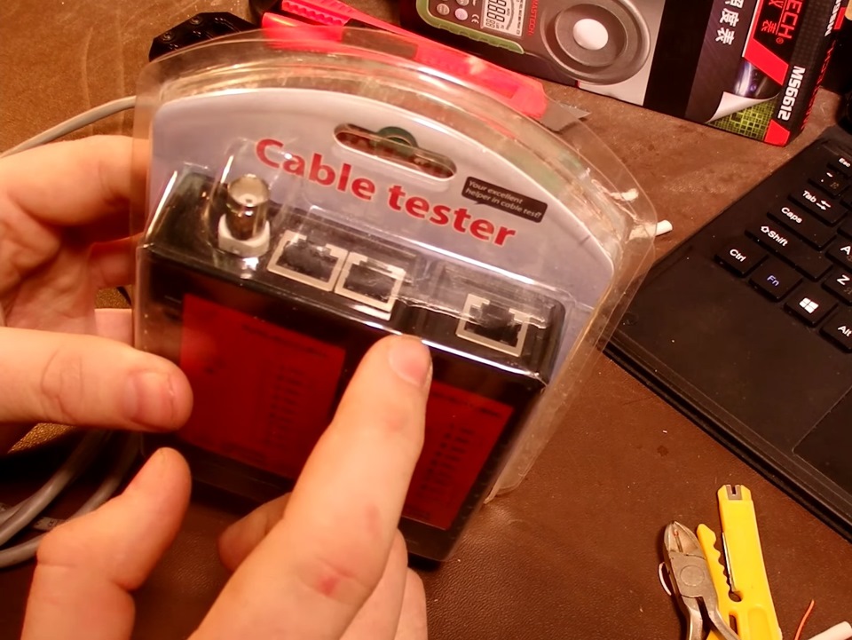
Устройство под малоинформативным названием NS-468 относится к самым простым и дешевым кабельным тестерам. С его помощью можно проверять кабели локальной сети и телефонные провода, для чего девайс снабжен гнездами RJ-45 (8 контактов) и RJ-11 (6 контактов). Устройство поставляется в прозрачной пластиковой упаковке. Кроме самого тестера в комплекте имеется инструкция – только на английском.
Девайс состоит из двух модулей – передатчика (обозначен как «master») и приемника («remote»). В передатчик нужно установить девятивольтовую батарейку типа «крона» (в комплекте отсутствует). Далее в подходящее гнездо на «хозяине» вставляется один конец кабеля, а в такое же гнездо на «удаленном» – другой. На передатчике есть трехпозиционный выключатель. Если сдвинуть его в положение On, светодиоды на тестере начнут мигать. Если переключить в S, темп мерцания замедлится.
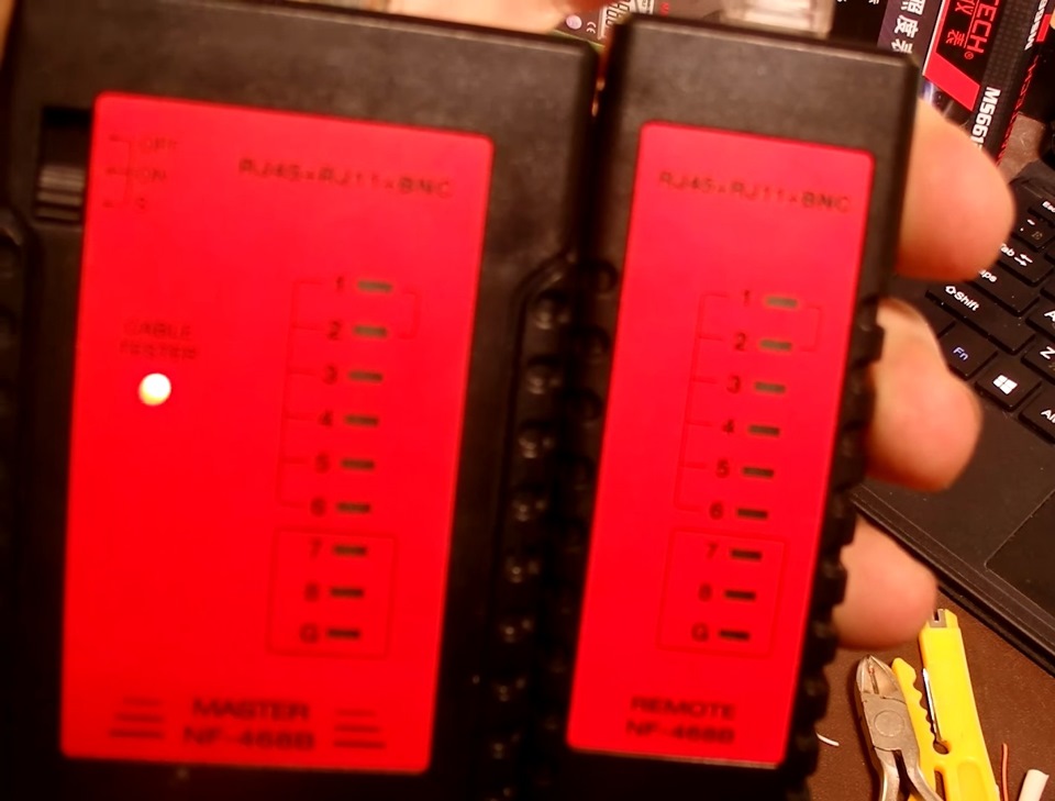
Если же сигнал вообще никуда не идет (например, штепсель не вставлен в разъем на тестере), мигает только один диод, над выключателем. А когда кабель вставлен в оба модуля, диоды под номерами с 1 до 8 поочередно загораются и на приемнике, и на передатчике – по крайней мере, если жилы кабеля целы, а концы обжаты правильно. Диод же, обозначенный буквой G, будет светиться только при наличии заземления.
Если один из диодов не загорается, значит, сигнал не проходит по жиле с этим номером. Допустим, если не горит диод 2 на передатчике, сигнал обрывается на втором слева проводнике в коннекторе, вставленном в передатчик. При замыкании жил на «мастере» диоды загораются как положено, а на приемнике не горят два (три, четыре) диода либо при загорании одного индикатора на передатчике на приемнике вспыхивают два. Эти проблемы чаще всего решаются переобжатием концов витой пары. Если оно не помогает, возможно, поврежден сам провод – в таком случае его придется заменить, так как данный тестер примитивен и не может указать, насколько далеко от конца кабеля разрыв (а бывают девайсы, которые могут и это, – они дороже и сложнее в обращении).
В современных сетях чаще всего используется схема обжатия без перекрещивания – порядок жил витой пары на концах кабеля совпадает. Если диоды на передатчике загораются строго по очереди, а на приемнике – в неправильном порядке, значит, проводники перепутаны местами. Например, если после шестого загорается сначала восьмой, а потом седьмой диод, значит, жилы 7 и 8 заняли места друг друга. Необходимо отрезать штепсель и обжать конец кабеля, внимательно проследив за корректным порядком жил – для этого на них сделана разноцветная изоляция (бело-оранжевая, оранжевая, бело-зеленая, синяя, бело-синяя, зеленая, бело-коричневая, коричневая). При проверке телефонных кабелей тестер используется точно так же, как с витой парой, только в таком проводе шесть жил, и гореть будут первые шесть диодов. Ну и штепсель надо вставлять в другой разъем, RJ-11.
И напоследок о внешнем виде прибора. Два его модуля – это две пластиковые коробочки светло-серого цвета, которые можно скреплять друг с другом. В таком виде его удобно возить с собой: один модуль отдельно от другого не потеряется – только оба вместе (смайл).
Нужен ли LAN-тестер NS-468 лично вам? Не факт. Но, в отличие от более дорогих кабельных тестеров, карман он не утянет ни в каком смысле слова – вес и размеры устройства невелики, как и его цена. А при необходимости проверить кабель локальной сети его возможностей чаще всего хватает. UP
- Устройство: NS-468
- Тип: кабельный тестер
- Типы разъемов: RJ-11, RJ-45
- Питание: батарея 9 В
- Габариты: 105 х 100 х 28 мм
Автор: DjFedos
№ 432
Описание товара:
SY-468 (NS-468, BS-468) Кабельный тестер для витой пары UTP/FTP RJ-45, телефонного кабеля RJ-11
Страна производства
КИТАЙ
AdType
Товар приобретен на продажу
Описание товара
Тестирование разомкнутых цепей, коротких замыканий, перекрестных соединений, раздельных соединений предназначен для витой пары UTP/FTP RJ-45, телефонного кабеля RJ-11.
Особенности и применение:
— Для тестирования кабелей витая пара, телефонных
— Поиск обрывов, коротких замыканий, перепутанных пар и проводников
— Входные порты RJ-45, RJ-11
— Питание: 9В (Крона, 1 шт., в комплект не входит)
Тестер для локальной сети NS-468N ( RJ45 / RG12 )
Тестирование кабеля витая пара с разъемом RJ45.
- Включить питание, переместив ползунок включения питания на значение ON (включено). Должен светиться индикатор питания.
- При проверке неэкранированного кабеля на основном и съемном блоке будут один за другим подсвечиваться символы от 1 до 8, и этот процесс будет повторяться.
- При проверке экранированного кабеля на основном и съемном блоке будут один за другим подсвечиваться символы от 1 до G, и этот процесс будет повторяться.
- Для изменения скорости тестирования необходимо переместить ползунок на значение S — медленно.
- Если в кабеле имеются обрывы, изменение порядка соединения проводов или их замыкание, результат проверки представлен в «Возможные неисправности кабеля. Пункт 3».
Тестирование кабеля витая пара с разъемом RJ11/RJ12.
- Включить питание, переместив ползунок включения питания на значение ON (включено). Должен светиться индикатор питания.
- При проверке кабеля с разъемом RJ11 на основном и съемном блоке будут один за другим подсвечиваться символы от 2 до 5, и этот процесс будет повторяться.
- При проверке кабеля с разъемом RJ12 на основном блоке и съемном устройстве будут один за другим подсвечиваться символы от 1 до 6, и этот процесс будет повторяться.
- Если в кабеле имеются обрывы, изменение порядка соединения проводов или их замыкание, результат проверки представлен в «Возможные неисправности кабеля. Пункт 3».
Возможные неисправности кабеля.
- При обрыве одного из проводов, например № 3, символы 3 на основном и съемном блоке не будут подсвечены.
- Если несколько проводов имеют обрыв, несколько индикаторов не будут загораться последовательно.
- Если провод в разъеме обжат на разных позициях, например провод 2 обжат на позиции 2 с одной стороны, а с другой на позиции 4, тогда тестер покажет такой результат:
Основной блок: 1-2-3-4-5-6-7-8-G.
Съемный блок: 1-4-3-2-5-6-7-8-G.
- Если два провода замкнуты накоротко, индикация произойдет только на основном блоке прибора. Если закорочены 3 провода, индикации не будет.
После окончания проверки отключить питание тестера, нажав на кнопку включения/выключения.
Подробности о наличии товара вы можете узнать по телефону: +7 (343) 379-08-09 или написав нам на электронную почту: info@radiomir96.ru
-
Page 1
BURGLAR ALARM PANEL BS-468… -
Page 2: Table Of Contents
Contents 1. Description ……………………….3 2. Instructions for the user ……………………4 2.1Basic operations ……………………..4 Complete system………………………… 4 Split system…………………………4 2.2 Armed system indication ………………….. 5 2.3 Advanced operations ……………………5 2.4 Main User menu ……………………..7 3.
-
Page 3: Description
1. Description The BS-468 is an 8 zone burglar alarm panel. Using the special expansion card BS-469 it can be expanded to 16 zones. For its operation, at least one BS-466 keyboard is required. Up-to 8 keyboards can be connected to the panel. Each keyboard has an additional zone for connecting magnetic contacts (zones 17–24).
-
Page 4: Instructions For The User
2. Instructions for the user 2.1Basic operations The panel has 1 main code (master) which by default is set to [1 2 3 4] and up-to 50 user codes which by default are not programmed. The system can operate with two different modes. Depending on the mode of operation, the arm and disarm operations differ.
-
Page 5: Armed System Indication
2.2 Armed system indication When the system is armed then next to the clock, instead of the Olympia electronics logo there is a lock symbol. Next to the lock symbol we can see which sections are armed. In this example we can see that the system is partially armed because only the C section is armed.
-
Page 6
(If a GSM is connected) PANEL SOFT VERSION TECHNICIAN INFO The selection «TECHNICIAN INFO» by default has information of SIGNAL LEVEL Olympia electronics. 11-4-2017 921468001_09_015… -
Page 7: Main User Menu
If “SIGNAL LEVEL” is selected and a GSM module is not connected NO GSM CONNECTED then the following message is shown. PRESS ‘#’ TO RETURN 2.4 Main User menu Via the user menu we can change critical parameters of the system. To enter the user menu we must know the master code.
-
Page 8
We enter the number of the password (i.e. 03) which we want to change and we see: 03:CHANGE PASSWORD — — — — After entering the 4 new digits the system request us to repeat them. We enter again the 4 digits. If the codes match then the change is made and the display shows the relative message. -
Page 9
With the selection «CHANGE DAY OF WEEK» we see: _ CHANGE DAY OF WEEK _ MONDAY With the up and down cursor key we select the required day and TUESDAY by using the (*) key we make the selection. WEDNESDAY THURSDAY FRIDAY SATURDAY… -
Page 10
Finally the MASTER MENU has the option «TIMERS». With this selection we can program up to 10 automatic arming or disarming procedures of all or part of the system. Selecting «TIMERS» we see the display below. If the «CHANGE TIMER» is selected then this means that the timer is active. If the «DELETE TIMER»… -
Page 11
By pressing the (*) key we see: We make the required selection of the function that we want the _ CHANGE ACTION _ timer to do and press the key (*). The system confirms the ARM ALL selection. DISARM ALL The event memory logs the arming or disarming of the system but ARM Α… -
Page 12: Installation Instructions
3. Installation instructions 3.1. Quick installation guide By default the panel has the following settings section Α Zone 1 : Zone with delay section Β Zone 2 : Zone with delay Ζone 3 : Zone without delay section Β Ζone 4 : Zone without delay section Β…
-
Page 13
All zones are on the same section and the system arms and disarms all together. On zone 1 the magnetic trap activated the bell on the keyboard to warn us that the door has opened. section Α 2. Zone 1 : Zone with delay section Β… -
Page 14
This program is identical to the previous program but with more zones for the store. section Α Zone 1 : Zone with delay section Α Zone 2 : Zone with delay section Α Zone 3 : Zone without delay section Α Zone 4 : Zone without delay section Α… -
Page 15: Connections
3.2. Connections Connecting the battery and the mains power supply For the battery there are two cables, red and black for connecting to the positive and negative pole respectively. Keyboard connections To facilitate the installation, the keyboard has two parts, the base and the main body. The base is the part that must be mounted to the wall.
-
Page 16: Siren Connections
Connecting 8 keyboards to the panel. The cables must be connected in such a way that will permit the connection of the device one after the other. No terminal should contain 3 cables or more. The jumpers of the terminal resistors must be placed only on the two outer most devices. On all the other devices is should be removed or left in a open position.
-
Page 17
For connecting the autonomous siren type BS-413 up-to 7 cables are required. On the terminals (+) και (-) connect the voltage (AS), (-) which charges the siren. When we supply the (ST) with 12V the siren and the beacon are activated. It is connected to the P1 contact of the panel which is programmed to provide 12V during an alarm and 0V during the idle state. -
Page 18: Zone Connections
Zone connections Connecting the panel with radars (infrared movement detectors, PIR) or other devices which require power. For the connection, 4 cables are required (6 if the TAMPER is connected). The 2 cables are connected to the (12V) and (-) of the panel and provide power to the respective terminals of all the detectors.
-
Page 19: Smoke And Heat Detector Connections
Smoke and heat detector connections The connection of the fire detectors must be done to a zone which has been programmed as a «FIRE» zone. The normally closed contacts of the relay on the base (NC,C) are connected in series with the resistor of the zone of the panel.
-
Page 20: Programming Via The Keyboard
3.3. Programming via the keyboard Let it be noted that when trying to change a setting in the user menu or the technician menu you can view the current value of the setting. The only menus that do not offer the preview of default values are the 2 menus «CALL ON»…
-
Page 21: Programming How The Passwords Function
By entering the technician’s password we enter the technician menu and we see: __ TECHNICIAN MENU __ EVENTS By selecting the «EVENTS» option we can erase the events log. If CODES we make this selection the system asks for a confirmation and then erases the entire events log.
-
Page 22: General Settings
SILENT ALARM. The code activates the silent alarm. When the user enters the code, the panel will disarm (if the panel is armed) and will remain in idle state (the siren will not sound, and the alarm leds will be off). The panel will call or send a message via BS-465 or BS-464 to the selected telephone numbers.
-
Page 23: Automatic Arming-Disarming
«AUTOMATIC BYPASS» By selecting YES, all zones that have be programmed with bypass capabilities (see zone programming), if during the arming are active (i.e. an open window) are bypassed automatically by the system. When the zones are deactivated (i.e. the window has closed) they are automatically activated.
-
Page 24: Zone Programming
We enter the hours and minutes that we want the timer to activate and we see: _ CHANGE DAY OF WEEK _ EVERY DAY We select the day of the week when we want the timer to activate. If we select «EVERY DAY» the timer will activate all of the days. MONDAY TUESDAY WEDNESDAY…
-
Page 25
«ZONE WITH DELAY». The zone will issue an alarm after an entrance delay. This selection is used for the magnetic contacts that are used for the main entrance and also for the radar the will detect the user before he reaches the panel to disarm it. «»ZONE WITHOUT DELAY». -
Page 26: Output Programming
zone. The zone is regarded again by the system when it stops being active ( i.e. when the window closes). If we select NO and the zone during the arming process is active (i.e. open window) and the automatic bypass has been selected, the system will warn us that the arming is not possible. For the last three setting if we select ZONE MODE the panel will automatically select the correct setting.
-
Page 27: Programming The Pstn Bs-465 Telephone Dialer
ALARM AND FAULT display. More option can be viewed only with the computer software ALARM ONLY PC-468 that accompanies the panel BS-468. FAULT ONLY PANIC AND FIRE ONLY Due to the fact that in this menu not all option are shown, the cursor TAMPER ONLY does not highlight the current option but always the top most.
-
Page 28: Programming The Gsm Bs-464 Telephone Dialer
After making the required selection it is time to enter the actual telephone number. Due to the fact that the ‘*’ and or ‘#’ can be part of the number, the LINE NUMBER ENTRY storage is done using the ‘Α’ key, the cancellation is done using ‘Β’ 6977123456———— key and finally with the ‘C’…
-
Page 29
ALL EVENTS can be viewed only with the computer software PC-468 that accompanies ALARM ONLY the panel BS-468. FAULT ONLY PANIC AND FIRE ONLY Due to the fact that in this menu not all option are shown, the cursor does ON ARM not highlight the current option but always the top most. -
Page 30
PIN number. Remove the card from the phone and replace it in the socket of the GSM card. Reinstall the GSM card on the panel BS-468. Please note that the PIN code is requested twice. For the code to be —- considered correct we must enter it correctly both times. -
Page 31: Resetting To Factory Default Passwords
3.4. Resetting to factory default passwords The main board of the panel contain 2 pins with the marking CODE RESET. With this we can reset the passwords to the factory defaults by following the procedure below: 1. Connect the cable SERVICE of the siren to a (-) on the panel. 2.
-
Page 32: Programming From The Computer
The programming of the panel can be done easily by using the special computer software PC-468 that is provided free by Olympia Electronics. To connect the panel to the computer a simple mini-USB cable is required. This is provided with the BS-468/KEYPAD as well as the newest version of the software.
-
Page 33: Connection Function
Connection function To establish a connection with the panel, connect the usb cable to the keyboard BS-466 and click on as shown in the screen above. The indicators on the bottom left corner must be green. After the connection is established the panel settings are shown. (below screen) Next the connected devices and the keyboards are shown.
-
Page 34
We can receive all the settings of the panel by clicking on , as shown below. The panel requests a password for this operation. We must enter either the technician code ( 9 9 9 9 ) or the main user password ( 1 2 3 4 ) to receive all the settings of the panel. Next we can set or view all the settings of the panel such as zones, passwords, events, timers and outputs. -
Page 35: Programming The Panel
Programming the panel We can view or alter the settings of the panel. The above settings can be altered only be using the keyboard but by using the software we have a better visual perspective and the programming is easier. Also by using the software we can easily synchronize the date and the time of the computer to that of the panel by clicking on the corresponding button.
-
Page 36
If for example we want to change the entrance time to 10 seconds press the up arrow next to the 7 second entrance time as shown below. We see that the entrance time 10 is highlighted. This means that we have changed this setting but the have not been stored yet. By clicking on the button «Send» a window is shown for sending the new settings to the panel. -
Page 37: Zone Settings
Zone settings To set the zones of the panel we select the option «Zones». And a screen like the one below is shown. The technician can alter the operation of each zone whereas the main user can give a name to each zone so it can be easily recognized.
-
Page 38: Password Settings
Password settings If the technician enters the password option he can change only the reaction, section and output as shown in the screen below. The technician can also make changes to the codes which can also be done from the BS-466 keyboard.
-
Page 39
When we enter a code it request for us to enter it 2 times in order to avoid errors. In the previous screen we a can see an option «Visible codes». With this option the main user can later if the codes will be shown or if they will be in the form an asterix. The screen above shows a typical system. -
Page 40: Events
Events We this option we can see all the events of the panel. Clicking the button «Receive» to view all the events that have occurred The columns shown are: Α/Α the number of the event Date and time of the event. Category.
-
Page 41: Timer Settings
Warning!! The events of the panel are not stored with the settings of the panel. If we want to have the events of the panel we can store them in a separate file by clicking the button «Save» on the lower right side as shown on the screen below. With the button «Open»…
-
Page 42: Output Settings
The screen above shows timer 2 used to disarm section A every Wednesday at 7:00 AM whereas timer4 arms the system every Wednesday at 7:00 PM. Output settings The option OUTPUTS is used to show all the outputs. The function is as described in altering the outputs by the BS-466 keyboard.
-
Page 43: New File
New file With this option we can start a new installation without the panel being connected. First we select what the panel will contain e.g. GSM, keyboards 1,2,5 and 6. Next we alter all the required settings and save the file using the selection File Save. Open file When we select to open a file, a window in shown like in the screen below.
-
Page 44: I — Olympia Application
Then we can do a transfer of the settings to the panel as shown in the screen above. I — OLYMPIA APPLICATION “Olympia Electronics Alarm” application is available for smart phones and tablets for Android or IOS. You can download it at Google play or Apple store.
-
Page 45: Technical Characteristics
4. Technical Characteristics Description BS-468 Burglar alarm system Power Supply 220-240V AC/50-60Hz Consumption 25VA Battery type Sealed lead acid (Pb) battery 12V / 7Ah Max (not included) Charger Stabilized power supply 13,8V / 400mA AS siren circuit The AS output powers the external sirens and is used to charge the battery of the siren with a rating of 13,8V 500mA.
-
Page 46: Peripheral Device Consumption Chart
Olympia Electronics reserves the right to repair or to replace the returned goods and to or not charge the buyer depending on the reason of defection. Olympia Electronics reserves the right to charge or not the buyer the transportation cost.
-
Page 47: Information Regarding The Installation
4.2. Information regarding the installation Passwords Master password: (1 2 3 4 ) ____________ Α/Α Α/Α Password Owner Function Password Owner Function Zones Section Section Section Α/Α (Α Β C) Α/Α (Α Β C) Α/Α (Α Β C) Area Area Area Various information Entry time : ________ seconds Exit time : _________ seconds…
Сегодня речь пойдет о тестере кабелей локальной сети и коаксиальных проводов. Это устройство будет полезно тем, кому время от времени приходится заниматься прокладкой компьютерной сети или установкой новых рабочих мест для пользователей, незаменимым будет инструмент и для телевизионщиков, монтажников видео наблюдения.
Конечно, можно обойтись и без подобного тестера, но иногда он сильно экономит время.
Естественно, тестировать короткие патч-корды таким тестером практически бессмысленно, вы и так видите поврежден ли кабель, и правильно ли он обжат. Но вот когда вы тянете связку витухи под потолком пару десятков метров, то потом прыгать и искать есть ли обрыв кабеля весьма проблематично. Особенно это касается ситуаций, когда сеть прокладывается в новом офисе, где еще нет компьютерной техники, и, соответственно, не чем проверить. Именно здесь простейший тестер поможет вам не «ударить в грязь лицом» и быть уверенным в своей работе.
Покупал ТУТ за 10$
Инструмент для обжима RJ45 RJ11 RJ12: Покупал тут за 5$
Инструкция на русском языке www.testers.ru/upload/iblock/156/nf_468_rus.pdf
С одной стороны к кабелю подключается главный блок (MASTER), с другой стороны — отсоединяемый (REMOTE), с которым и следует ходить и проверять кабель, так как, если брать с собой главный блок, то вы не сможете определить неправильный порядок жил. На master блоке индикаторы всегда будут мигать по порядку.
Тестер включается единственным переключателем. Хотя отмечу, что на переключателе есть 3 положения, в одном из которых он выключен, а другие положения влияют на скорость мигания индикаторов. На мой взгляд, почти бесполезная функция.
Устройство имеет разъемы 8P8C и 6P6C 4P4C BNC(RJ-45, RJ-11, RJ-12), которые подойдут для тестирования компьютерных и телефонных коннекторов, а также коаксиальных кабелей (антенны, тарелки, видео наблюдение и т.д.)
Светодиодные индикаторы поочередным миганием информируют нас о том, что соответствующая жила целая. Если нарушена очередность мигания индикаторов, это сигнализирует нарушении последовательности обжатия жил в кабеле.
Описание из сети:
Устройство NS-468B предназначено для проверки витой пары, телефонного и коаксиального кабеля на предмет короткого замыкания или обрыва провода. Кроме того, с помощью кабельного тестера NS-468B, можно проверить правильность подключения витой пары.
Технические возможности:
Применяемые коннекторы: RJ45 – витая пара, RJ11 – телефонный, BNC – коаксиальный.
Показывает наличие постоянного напряжения в паре проводов и определяет их полярность (плюс и минус).
Подает звуковой сигнал при коротком замыкании или обнаружении обрыва.
Помогает определить правильность схемы разводки витой пары.
Работа переключателя: «ON» – тестирование с обычной скоростью, «S» – тестирование с меньшей скоростью, «OFF» — выключение питания.
Питание: батарея 9 В типа «крона», потребление — 25 мА.
Размер: 10,5х10,5х2,6 см
В видео специально для теста я повредил несколько жил кабеля, чтобы проверить, как это отображается на устройстве. Индикатор этой жилы просто не загорается, когда до него доходит очередь, что вполне логично.
По большому счету, это устройство можно приспособить для проверки целостности практически любого кабеля. Думаю, админы, монтажники ЛВС, монтажники видеонаблюдени должны иметь такой девайс в своем арсенале, и он не раз им поможет. Вот такой небольшой обзор на сегодня.