-
Contents
-
Table of Contents
-
Troubleshooting
-
Bookmarks
Quick Links
Related Manuals for Inovance MD310 Series
Summary of Contents for Inovance MD310 Series
-
Page 2: Table Of Contents
Contents Safety Information and Precautions �������������������������������������������������������������������������������������������������������2 1� Product Information ���������������������������������������������������������������������������������������������������������������������������3 1.1 Designation …………………………3 1.2 Nameplate…………………………… 3 1.3 General Specifications ………………………. 4 2 Wiring ��������������������������������������������������������������������������������������������������������������������������������������������������5 2�1 Typical Wiring ���������������������������������������������������������������������������������������������������������������������������������������������������� 5 2�2 Terminals ����������������������������������������������������������������������������������������������������������������������������������������������������������� 6 2.3 Control Circuit Wire Size and Torque Specification ������������������������������������������������������������������������������������������� 7 2�4 EMC Jumper/Screw �������������������������������������������������������������������������������������������������������������������������������������������…
-
Page 3
This responsibility lies with the user or their machine/process system integrator� The system integrator/designer must ensure the complete system is safe and designed according to the relevant safety standards� Inovance Technology and Authorized Distributors can provide recommendations related to the AC drive to ensure long term safe operation�… -
Page 4: Designation
1 Product Information 1� Product Information 1�1 Designation MD310 Mark Built-in Braking Unit MD310 series AC drive Null Voltage Class Mark 18.5 Mark Three-phase 380 V 0.75 18.5 Applicable motor, (kW) 1�2 Nameplate Nameplate MODEL: MD310T0�7B AC drive model INPUT: 3PH 380-440 VAC, 3�4 A, 50/60 Hz…
-
Page 5: General Specifications
1 Product Information 1.3 General Specifications Voltage Class Three-phase 380 VAC Drive Model MD310 MD310 MD310 MD310 MD310 MD310 MD310 MD310 MD310 MD310 T0�4B T0�7B T1�5B T2�2B T3�7B T5�5B T7�5B T11B T15B T18�5B Frame Size Dimension H [mm] W [mm] D [mm] 175�5 A [mm]…
-
Page 6: Typical Wiring
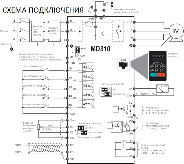
2 Wiring 2 Wiring 2�1 Typical Wiring Wiring of Three-phase 380 VAC Power Supply ■ Braking resistor (optional) MCCB ( — ) P(+) MD310 Power supply Three-phase 380 V 50/60 Hz +24V OP is connected to +24V in default, please pay attention to jumper J7 +24V Analog output…
-
Page 7: Terminals
2 Wiring 2�2 Terminals Terminals of Main Circuit ■ Table 2-1: Main circuit terminals of three-phase Terminal Terminal Name Description R, S, T Three-phase power supply input terminals Connect to the three-phase AC power supply� P(+), (-) Positive and negative terminals of DC bus Common DC bus input point�…
-
Page 8: Control Circuit Wire Size And Torque Specification
2 Wiring 2.3 Control Circuit Wire Size and Torque Specification Please use a ferrule-type terminal with insulated sleeves� Prepare wire ends with insulated sleeves before connecting to the drive� See the following figure for ferrule dimensions. 5 mm Terminal Block Single Wire (AWG/mm Twisted Wire (AWG/mm Tightening Torque (N·m)
-
Page 9: Grid System Requirement
2 Wiring For the MD310T7.5B to MD310T18.5B, remove the No.2 EMC screw, as shown in the following figure. Figure 2-2 EMC screw position EMC screw VDR screw Note The screw is connected by default� The screw cannot be re-connected once it is cut� This will result in an increase in leakage current to ground during drive running� Take full consideration before cutting the jumper�…
-
Page 10: Logic Of Control
3 Easy Setup 3 Easy Setup 3�1 Logic of Control Complete Timing Diagram ■ Fr equency F0-08 [x.x Hz] F0-18 F0-17 F6-09 F6-08 [x.x Sec] [x.x Sec] [x.x% ] [x.x% ] Fr equency F6-11 [ x.x Hz]: default 0.0 Hz output DC injection braking 2 frequency threshold command…
-
Page 11
3 Easy Setup Timing Diagram Description ■ Event Description Para� No� Status -The AC drive waits for the RUN signal� Inhabit -The AC drive receives the Forward RUN command� -The IGBT becomes active� -DC injection braking 1/Pre-excitation is enabled if F6-06 > 0� F6-05 (if F6-00 = 0, it is «DC injection braking 1»;… -
Page 12: Step By Step Setup
3 Easy Setup 3�2 Step By Step Setup Setup Flowchart ■ Check nameplate and wiring Refer to Chapters 1 and 2 Apply main power to AC drive Get familiar with keypad Set motor parameters Set motor control mode Perform motor tuning if it’s SVC control mode Set frequency reference Set operation mode Set start mode and stop mode…
-
Page 13
3 Easy Setup Step 1: Get Familiar With Keypad Indicators LED display Increment key Programming key Confirm key Multi-function key Decrement key Shift key RUN key Stop/Reset key Indicators ■ FWD/REV : It indicates forward or reverse rotation� OFF indicates forward rotation and ON indicates reverse rotation� TUNE/TC : ON indicates torque control mode, blinking slowly indicates auto-tuning state, blinking quickly indicates fault state�… -
Page 14
3 Easy Setup Keys On Keypad ■ Key Name Function Programming Enter or exit Level I menu� Confirm Enter the menu interfaces level by level, and confirm the parameter setting. ENTER Increment Increase data or Para� No�� Decrement Decrease data or Para� No�� Select the displayed parameters in turn in the stop or running state, and select the digit to be Shift modified when modifying parameters. -
Page 15
3 Easy Setup Keypad Operation ■ F0 27 ENTER ENTER ENTER ENTER F0 02 50.00 F0 01 F0 02 F0 27 save the value F0 02 Para� No� Arrangement ■ Para� Group Description Remark F0 to FP Standard parameter group Standard function parameters A0 to AC Advanced parameter group… -
Page 16
3 Easy Setup Step 2: Set Motor Parameters Para� No� Para� Name Setting Range Unit Default Commission F1-00 Motor type selection 0: Common asynchronous motor N�A� 1: Variable-frequency asynchronous motor F1-01 Rated motor power 0�1 to 30�0 Model dependent F1-02 Rated motor voltage 1 to 1000 Model… -
Page 17
3 Easy Setup Para� No� Para� Name Setting Range Unit Default Commission F0-07 Frequency source N�A� superposition selection Main and auxiliary calculation relationship 0: Main + Auxiliary 1: Main – Auxiliary 2: Maximum of main and auxiliary 3: Minimum of main and auxiliary Frequency reference setting channel selection 0: Main frequency reference setting channel 1: Main + auxiliary operation… -
Page 18
3 Easy Setup Step 6: Select Operation Mode Para� No� Para� Name Setting Range Unit Default Commission F0-02 Command source 0: Keypad control N�A� selection 1: Terminal control 2: Communication control F4-11 Terminal command 0: Two-wire control mode 1 N�A� mode 1: Two-wire control mode 2 2: Three-wire control mode 1… -
Page 19
3 Easy Setup Step 7: Set Start Mode And Stop Mode Para� No� Para� Name Setting Range Unit Default Commission F6-00 Start mode 0: Direct startup N�A� 1: Reserved 2: Pre-excited startup F6-10 Stop mode 0: Decelerate to stop N�A� 1: Coast to stop Step 8: Set Acceleration And Deceleration Parameters Para�… -
Page 20
3 Easy Setup Para� No� Para� Name Setting Range Unit Default Commission F4-03 DI4 function selection 22: PID pause N�A� 23: PLC status reset Multi-reference terminal 1 24: Wobble pause 25: Counter input 26: Counter reset 27: Length count input 28: Length reset 29: Torque control prohibited F4-04… -
Page 21
3 Easy Setup DO Setting ■ Para� No� Para� Name Setting Range Unit Default Commission F5-00 FM terminal output 0: Pulse output (FMP) N�A� mode 1: Switch signal output (FMR) F5-01 FMR function 0: No output N�A� (open-collector output 1: AC drive running No output terminal) selection 2: Fault output… -
Page 22
3 Easy Setup Para� No� Para� Name Setting Range Unit Default Commission F5-17 FMR output delay time 0�0 to 3600�0 0�0 F5-18 Relay 1 output delay 0�0 to 3600�0 0�0 time F5-19 Relay 2 output delay 0�0 to 3600�0 0�0 time F5-20 DO1 output delay time… -
Page 23
3 Easy Setup Step 12: Set DC Injection Braking/Pre-excitation If Needed Para� No� Para� Name Setting Range Unit Default Commission F6-00 Start mode 0: Direct startup N�A� 1: Reserved 2: Pre-excited startup F6-05 DC injection braking 1 0 to 100 level F6-06 DC injection braking 1… -
Page 24: Faults And Solutions
4 Troubleshooting 4 Troubleshooting 4�1 Faults and Solutions Display Fault Name Possible Causes Solutions Err02 Overcurrent during 1� The output circuit is short circuited� 1: Eliminate short circuit� acceleration 2� The acceleration time is too short� 2: Increase the acceleration time� 3�…
-
Page 25
4 Troubleshooting Display Fault Name Possible Causes Solutions Err08 Control power fault The input voltage exceeds the allowed range� Adjust the input voltage to within the allowed range� Err09 Undervoltage 1� Instantaneous power failure occurs� 1: Reset the fault� 2� The input voltage exceeds the allowed range 2: Adjust the input voltage to within the allowed range�… -
Page 26
4 Troubleshooting Display Fault Name Possible Causes Solutions Err28 User-defined fault 2 1. The user-defined fault 2 signal is input via DI Reset the fault� 2. The user-defined fault 2 signal is input via VDI� Err29 Accumulative power- The accumulative power-on time reaches the Clear the record by performing parameter on time reached setting of F8-16�… -
Page 27
4 Troubleshooting 4�2 Common Symptoms And Diagnostics Fault Name Possible Causes Solutions There is no display at power- 1� There is no power supply or the power supply is 1: Check the power supply� on� too low� 2 to 5: Seek for maintenance� 2�… -
Page 28: General Parameters
5 Parameter Table 5 Parameter Table 5�1 General Parameters Group F0: Standard Parameters ■ Para� No� Para� Name Setting Range Unit Default Commission F0-01 Motor 1 control mode 0: Sensorless vector control (SVC) N�A� 2: Voltage/Frequency control (V/F) F0-02 Command source 0 to 2 N�A�…
-
Page 29
5 Parameter Table Para� No� Para� Name Setting Range Unit Default Commission 0: Not retentive N�A� F0-23 Retentive of digital setting frequency upon 1: Retentive stop F0-24 Motor parameter group 0: Motor parameter group 1 N�A� selection 1: Motor parameter group 2 F0-25 Acceleration/ 0: Max�… -
Page 30
5 Parameter Table Group F2: Vector Control ■ Para� No� Para� Name Setting Range Unit Default Commission F2-00 Speed loop proportional 1 to 100 N�A� gain 1 F2-01 Speed loop integral time 1 0�01 to 10�00 0�50 F2-02 Switchover frequency 1 0�00 to F2-05 5�00 F2-03… -
Page 31
5 Parameter Table Group F3: V/F Control ■ Para� No� Para� Name Setting Range Unit Default Commission F3-00 V/F curve setting 0 to 9 N�A� F3-01 Torque boost 0�0 to 30�0 0�0 F3-02 Cut-off frequency of torque 0�00 to max output frequency 50�00 boost F3-03… -
Page 32
5 Parameter Table Group F4: Input Terminals ■ Para� No� Para� Name Setting Range Unit Default Commission F4-00 DI1 function selection 0 to 59 N�A� F4-01 DI2 function selection 0 to 59 N�A� F4-02 DI3 function selection 0 to 59 N�A�… -
Page 33
5 Parameter Table Para� No� Para� Name Setting Range Unit Default Commission F4-34 Setting for AI less than 000 to 111 N�A� minimum input F4-35 DI1 delay time 0�0 to 3600�0 0�0 F4-36 DI2 delay time 0�0 to 3600�0 0�0 F4-37 DI3 delay time 0�0 to 3600�0… -
Page 34
5 Parameter Table Group F6: Start/Stop Control ■ Para� No� Para� Name Setting Range Unit Default Commission F6-00 Start mode 0: Direct startup N�A� 1: Reserved 2: Pre-excited startup (asynchronous motor) F6-01 Mode of catching a 0: From stop frequency N�A�… -
Page 35
5 Parameter Table Group F7: Keypad Control And LED Display ■ Para� No� Para� Name Setting Range Unit Default Commission F7-01 MF�K Key function selection 0 to 5 N�A� F7-02 STOP/RESET key function 0 to 1 N�A� F7-03 LED display running 0000 to FFFF N�A�… -
Page 36
5 Parameter Table Group F8: Auxiliary Functions ■ Para� No� Para� Name Setting Range Unit Default Commission F8-00 JOG running frequency 0�00 to max frequency 2�00 F8-01 JOG acceleration time 0�0 to 6500�0 20�0 F8-02 JOG deceleration time 0�0 to 6500�0 20�0 F8-03 Acceleration time 2… -
Page 37
5 Parameter Table Para� No� Para� Name Setting Range Unit Default Commission F8-28 Frequency detection value 0�00 to max frequency N�A� 50�00 (FDT2) F8-29 Frequency detection 0�0 to 100�0 (FDT2 level) 5�0 hysteresis (FDT2 hysteresis) F8-30 Detection value 1 of any 0�00 to max frequency 50�00 frequency reaching… -
Page 38
5 Parameter Table Group F9: Fault And Protection ■ Para� No� Para� Name Setting Range Unit Default Commission F9-00 Motor overload protection 0: Disabled N�A� 1: Enabled F9-01 Motor overload protection 0�20 to 10�00 N�A� 1�00 gain F9-02 Motor overload pre-warning 50 to 100 coefficient F9-07… -
Page 39
5 Parameter Table Para� No� Para� Name Setting Range Unit Default Commission F9-38 Output terminal status upon N�A� N�A� N�A� 1st fault F9-39 Frequency upon 1st fault N�A� N�A� N�A� F9-40 Current upon 1st fault N�A� N�A� N�A� F9-41 Bus voltage upon 3rd fault N�A�… -
Page 40
5 Parameter Table Group FA: Process Control And PID Function ■ Para� No� Para� Name Setting Range Unit Default Commission FA-00 PID reference source 0 to 6 N�A� FA-01 PID digital reference 0�0 to 100�0 50�0 FA-02 PID feedback source 0 to 8 N�A�… -
Page 41
5 Parameter Table Group FB: Wobble Frequency, Fixed Length And Count ■ Para� No� Para� Name Setting Range Unit Default Commission FB-00 Wobble setting mode 0: Relative to the central frequency N�A� 1: Relative to the max frequency FB-01 Wobble frequency amplitude 0�0 to 100�0 0�0 FB-02… -
Page 42
5 Parameter Table Para� No� Para� Name Setting Range Unit Default Commission FC-25 Acceleration/deceleration time 0 to 3 N�A� of simple PLC reference 3 FC-26 Running time of simple PLC 0�0 to 6500�0 s or h 0�0 reference 4 FC-27 Acceleration/deceleration time 0 to 3 N�A�… -
Page 43
5 Parameter Table Group FD: Communication ■ Para� No� Para� Name Setting Range Unit Default Commission FD-00 Baud rate 0000 to 9999 N�A� 5005 FD-01 Data format symbol 0 to 3 N�A� FD-02 Local address 0: Broadcast address; N�A� 1 to 247 FD-03 Response delay 0 to 20… -
Page 44
5 Parameter Table Group FE: User-Defined Parameters ■ Para� No� Para� Name Setting Range Unit Default Commission FE-00 User-defined function code 0 F0-00 to FP-xx, N�A� F0-01 A1-00 to Ax-xx, FE-01 User-defined function code 1 N�A� F0-02 U0-xx to U0-xx FE-02 User-defined function code 2 N�A�… -
Page 45
5 Parameter Table Group FP: Para� No� Management ■ Para� No� Para� Name Setting Range Unit Default Commission FP-00 User password 0 to 65535 N�A� FP-01 Parameter initialization 0: No operation N�A� 01: Restore factory settings except motor parameters 02: Clear records 04: Restore user backup parameters 501: Back up current user parameters 10: Initialization of power cable payoff… -
Page 46
5 Parameter Table Group A1: Virtual DI/DO ■ Para� No� Para� Name Setting Range Unit Default Commission A1-00 VDI1 function selection 0 to 59 N�A� A1-01 VDI2 function selection 0 to 59 N�A� A1-02 VDI3 function selection 0 to 59 N�A�… -
Page 47
5 Parameter Table Group A2: Motor 2 Parameters ■ Para� No� Para� Name Setting Range Unit Default Commission A2-00 Motor type selection 0: Common asynchronous motor N�A� 1: Variable frequency asynchronous motor A2-01 Rated motor power 0�1 to 30�0 Model dependent A2-02 Rated motor voltage… -
Page 48
5 Parameter Table Para� No� Para� Name Setting Range Unit Default Commission A2-53 Torque adjustment proportional 0 to 60000 N�A� gain A2-54 Torque adjustment integral gain 0 to 60000 N�A� A2-55 Speed loop property 00 to 11 N�A� A2-56 Torque feedforward gain 20 to 100 N�A�… -
Page 49
5 Parameter Table Group A6: AI Curve Setting ■ Para� No� Para� Name Setting Range Unit Default Commission A6-00 AI curve 4 minimum input -10�00 to A6-02 0�00 A6-01 Corresponding setting of AI -100�0 to 100�0 0�0 curve 4 minimum input A6-02 AI curve 4 inflexion 1 input A6-00 to A6-04… -
Page 50
5 Parameter Table Group AC: AI/AO Correction ■ Para� No� Para� Name Setting Range Unit Default Commission AC-00 AI1 measured voltage 1 -10�000 to 10�000 Factory corrected AC-01 AI1 displayed voltage 1 -10�000 to 10�000 Factory corrected AC-02 AI1 measured voltage 2 -10�000 to 10�000 Factory corrected… -
Page 51: Monitoring Parameters
5 Parameter Table 5�2 Monitoring Parameters Group U0: Monitoring ■ Para� No� Para� Name Setting Range Unit Default Commission U0-00 Running frequency N�A� N�A� U0-01 Set frequency N�A� N�A� U0-02 Bus voltage N�A� N�A� U0-03 Output voltage N�A� N�A� U0-04 Output current N�A�…
-
Page 52
5 Parameter Table Group U3: Extension Card Communication Control ■ Para� No� Para� Name Setting Range Unit Default Commission U3-00 to Reserved N�A� N�A� N�A� U3-15 U3-16 Frequency setting N�A� N�A� U3-17 Control command N�A� N�A� N�A� U3-18 DO control N�A�… -
Page 53
5 Parameter Table — 52 -…
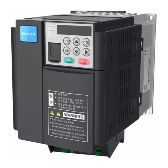
MD310T15B Преобразователь частоты INOVANCE MD310, 15кВт — 150%, 380В. MD310T15B частотный преобразователь компании INOVANCE имеет основные характеристики: Напряжение: 380В; Номинальная мощность двигателя, кВт: 15; Выходной ток, А: 32; Диапазон выходной частоты (скалярный режим), Гц: 0-600Гц; Диапазон выходной частоты (векторный режим), Гц: 0-300Гц. Модель MD310T15B INOVANCE вы можете приобрести по доступной цене в нашем магазине. Если остались вопросы по данной модели частотного преобразователя MD310T15B свяжитесь с нашими менеджерами удобным для Вас способом!
Небольшой размер, высокая производительность, параллельная установка нескольких приводов сохраняет место.
СТАБИЛЬНАЯ РАБОТА ПРИ ПРОВАЛАХ НАПРЯЖЕНИЯ
Данная функция позволяет преобразователю работать в случае снижения напряжения. В некоторых случаях, привод снижает выходную частоту и использует энергию, вырабатываемую двигателем, для уменьшения разницы напряжения, тем самым продолжая работать короткое время.
ОПТИМИЗАЦИЯ РЕЖИМА ТОРМОЖЕНИЯ
Функция перевозбуждения эффективно сдерживает рост напряжения в звене постоянного тока во время торможения, что позволяет избежать частых ошибок, связанных с перенапряжением.
Встроенный ПИД-регулятор совместно с источником задания частоты позволяет легко реализовать систему автоматического управления процессом, например, поддержания постоянной температуры, давления или натяжения.
МЕХАНИЧЕСКОЕ КАЧАНИЕ ЧАСТОТЫ
Для производства текстильной продукции и химических волокон данная функция позволяет создавать однородный материал.
ПЕРЕКЛЮЧЕНИЕ МЕЖДУ НЕСКОЛЬКИМИ ДВИГАТЕЛЯМИ
Доступны две группы параметров для двигателей, что позволяет управлять двумя двигателями в разные временные промежутки.
Порт RS485 поддерживает протокол Modbus- RTU. Также возможна передача данных по про- токолам CANopen и CANlink, что помогает реа- лизовать быстрый обмен информацией. В режиме мониторинга MD310 позволяет следить за изменениями параметров и пользоваться функцией виртуального осциллографа.
Защиты: от потери входной фазы, замыкания обмотки двигателя на землю, межфазного короткого замыкания двигателя. Все защиты гарантируют надёжную работу.
ЭКСПЛУАТАЦИЯ
■ температура модуля и радиатора может отслеживаться по сети.
■ суммарное потребление электроэнергии, время работы и время включения может передаваться на компьютер оператора по сети.
■ разрешается выбрать режим работы вентилятора: при подаче напряжения или при работе преобразователя. Это позволяет продлить срок службы вентилятора.
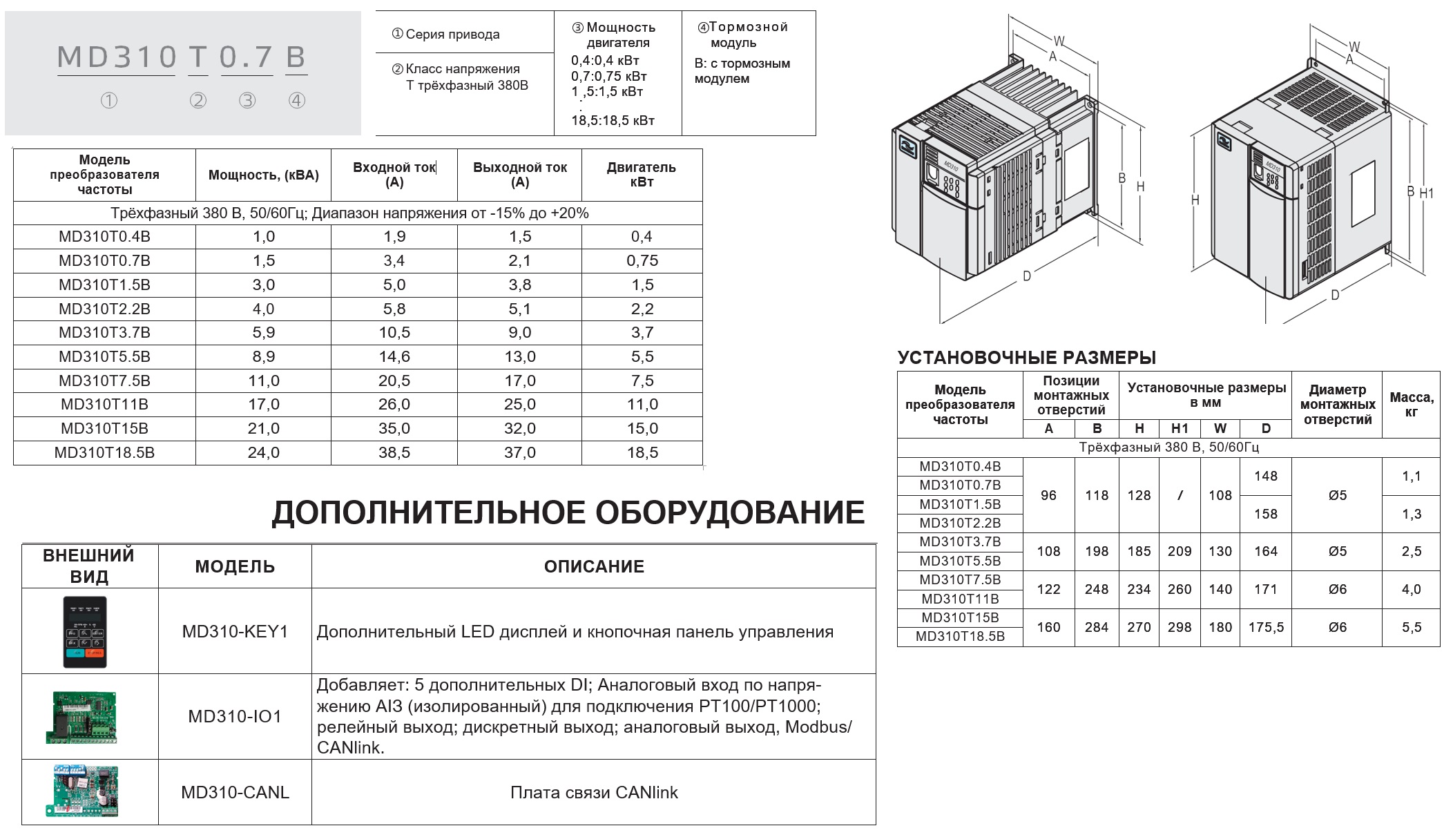
| Характеристики частотного преобразователя и доп.оборудования: | |
| Входное напряжение: | 380В |
| Номинальная мощность: | 15кВт |
| Номинальный ток: | 32A |
| Диапазон выходной частоты: | 0-600Гц |
| Габариты: | 270*180*1755мм |
| Перегрузочная способность по току: | 150%(60c);180%(2c) |
| Количество дискретных входов: | 5шт |
| Количество аналоговых входов: | 2шт |
| Тип аналогового входа №1: | 0-10В/0-20мА |
| Тип аналогового входа №2: | 0-10В/0-20мА |
| Количество дискретных выходов: | 2шт |
| Количество аналоговых выходов: | 1шт |
| Тип аналогового выхода №1: | 0-10В/0-20мА |
| Количество релейных выходов: | 1шт |
| Тип релейного выхода №1: | НО/НЗ |
| Степень защиты: | IP20 |
| Диапазон рабочих температур: | -10…+40°С |
| Поддержка протокола Modbus: | да |
| Встроенный блок питания 24В: | да |
| Защита от повышенного напряжения: | да |
| Защита от пониженного напряжения: | да |
| Защита от перегрузки двигателя: | да |
| Защита от потери входной фазы: | да |
| Защита от потери выходной фазы: | да |
| Тормозной блок: | встроенный |
| ЭМС фильтр: | отсутствует |
| Вес: | 5,5кг |
| Встроенный ПИД: | да |
| Съемная панель: | нет |
| Метод управления: | векторный/скалярный |
| Пусковой момент: | 1Гц/100% (скалярное управление);0,5Гц/150% (векторное управление) |
| Диапазон регулирования скорости: | 1:50 (скалярное управление);1:100 (векторное управление) |
| Точность поддержания скорости: | ±1 (скалярное управление);±0,5 (векторное управление) |
| Коммуникационные возможности на заказ: | CANopen, CANlink |
Руководство пользователя MD310 (RUS)
 |
[Page 1] Inovance MD310 Series … |
 |
[Page 2] Inovance MD310 Series Contents Safety Information and Precautions ���������������������������������������������������������������������… |
 |
[Page 3] Inovance MD310 Series Safety Information and Precautions — 2 — Safety Information and Precautions This guide is packaged together with the product … |
 |
[Page 4] Inovance MD310 Series 1 Product Information — 3 — 1� Product Information 1�1 De… |
 |
[Page 5] Inovance MD310 Series 1 Product Information — 4 — 1.3 General Specications Voltage Class Three-phase 380 VAC Drive Model MD310 T0�4B MD310 … |
 |
[Page 6] Inovance MD310 Series 2 Wiring — 5 — 2 Wiring 2�1 Typical… |
 |
[Page 7] Inovance MD310 Series 2 Wiring — 6 — 2�2 Terminals ■ Terminals of Main Circuit Table 2-1: Main circuit terminals of three-phase Terminal Terminal Name Description R, S, T Three-phase power supply input… |
 |
[Page 8] Inovance MD310 Series 2 Wiring — 7 — 2.3 Control Circuit Wir… |
 |
[Page 9] Inovance MD310 Series 2 Wiring — 8 — For the MD310T7.5B to MD310T18.5B, remove the No.2 EMC screw, as shown in the following gure. Figure 2-2 EMC screw position VDR screw EMC screw 1 2 Note The screw is… |
 |
[Page 10] Inovance MD310 Series 3 Easy Setup — 9 — 3 Easy Setup 3�1 Logic of Control �… |
 |
[Page 11] Inovance MD310 Series 3 Easy Setup — 10 — ■ Timing Diagram Description Event Description Para� No� Status t1 -The AC drive waits for the R… |
 |
[Page 12] Inovance MD310 Series 3 Easy Setup — 11 — 3�2 Step By Step Setup ■ Setup Flo… |
 |
[Page 13] Inovance MD310 Series 3 Easy Setup — 12 — Step 1: Get Familiar With Keypad Indicators LED display Confirm key Shift key Stop/Reset key … |
 |
[Page 14] Inovance MD310 Series 3 Easy Setup — 13 — ■ Keys On Keypad Key Key Name Functi… |
 |
[Page 15] Inovance MD310 Series 3 Easy Setup — 14 — ■ Keypad Operation F0 U0 AC … A2 A1 FP F0 27 … … F1 F0 02 2 50.00 F0 F0 F0 01 0 F0 … |
 |
[Page 16] Inovance MD310 Series 3 Easy Setup — 15 — Step 2: Set Motor Parameters Para� No�… |
 |
[Page 17] Inovance MD310 Series 3 Easy Setup — 16 — Para� No� Para� Name Setting Range Unit Default Commission F0-07 Frequency source superposition s… |
 |
[Page 18] Inovance MD310 Series 3 Easy Setup — 17 — Step 6: Select Operation Mode Para� No… |
 |
[Page 19] Inovance MD310 Series 3 Easy Setup — 18 — Step 7: Set Start Mode And Stop Mode Para� No� Para� Name Setting Range Unit Default Commission F6… |
 |
[Page 20] Inovance MD310 Series 3 Easy Setup — 19 — Para� No� Para� Name Setting Range … |
 |
[Page 21] Inovance MD310 Series 3 Easy Setup — 20 — ■ DO Setting Para� No� Para� Name Setting Range Unit Default Commission F5-00 FM terminal outp… |
 |
[Page 22] Inovance MD310 Series 3 Easy Setup — 21 — Para� No� Para� Name Setting Range … |
 |
[Page 23] Inovance MD310 Series 3 Easy Setup — 22 — Step 12: Set DC Injection Braking/Pre-excitation If Needed Para� No� Para� Name Setting Range Unit… |
 |
[Page 24] Inovance MD310 Series 4 Troubleshooting — 23 — 4 Troubleshooting 4�1 Faults and So… |
 |
[Page 25] Inovance MD310 Series 4 Troubleshooting — 24 — Display Fault Name Possible Causes Solutions Err08 Control power fault The input voltage exceeds the allowed ran… |
 |
[Page 26] Inovance MD310 Series 4 Troubleshooting — 25 — Display Fault Name Possible Causes Solu… |
 |
[Page 27] Inovance MD310 Series 4 Troubleshooting — 26 — 4�2 Common Symptoms And Diagnostics Fault Name Possible Causes Solutions There is no display at power- on� … |
 |
[Page 28] Inovance MD310 Series 5 Parameter Table — 27 — 5 Parameter Table 5�1 General Parame… |
 |
[Page 29] Inovance MD310 Series 5 Parameter Table — 28 — Para� No� Para� Name Setting Range Unit Default Commission F0-23 Retentive of digital s… |
 |
[Page 30] Inovance MD310 Series 5 Parameter Table — 29 — ■ Group F2: Vector Control Para� N… |
 |
[Page 31] Inovance MD310 Series 5 Parameter Table — 30 — ■ Group F3: V/F Control Para� No� Para� Name Setting Range Unit Default Commission F… |
 |
[Page 32] Inovance MD310 Series 5 Parameter Table — 31 — ■ Group F4: Input Terminals Para� … |
 |
[Page 33] Inovance MD310 Series 5 Parameter Table — 32 — Para� No� Para� Name Setting Range Unit Default Commission F4-34 Setting for AI less th… |
 |
[Page 34] Inovance MD310 Series 5 Parameter Table — 33 — ■ Group F6: Start/Stop Control Para�… |
 |
[Page 35] Inovance MD310 Series 5 Parameter Table — 34 — ■ Group F7: Keypad Control And LED Display Para� No� Para� Name Setting Range Unit D… |
 |
[Page 36] Inovance MD310 Series 5 Parameter Table — 35 — ■ Group F8: Auxiliary Functions Para… |
 |
[Page 37] Inovance MD310 Series 5 Parameter Table — 36 — Para� No� Para� Name Setting Range Unit Default Commission F8-28 Frequency detection val… |
 |
[Page 38] Inovance MD310 Series 5 Parameter Table — 37 — ■ Group F9: Fault And Protection Par… |
 |
[Page 39] Inovance MD310 Series 5 Parameter Table — 38 — Para� No� Para� Name Setting Range Unit Default Commission F9-38 Output terminal status … |
 |
[Page 40] Inovance MD310 Series 5 Parameter Table — 39 — ■ Group FA: Process Control And PID … |
 |
[Page 41] Inovance MD310 Series 5 Parameter Table — 40 — ■ Group FB: Wobble Frequency, Fixed Length And Count Para� No� Para� Name Setting Ra… |
 |
[Page 42] Inovance MD310 Series 5 Parameter Table — 41 — Para� No� Para� Name Setting Range… |
 |
[Page 43] Inovance MD310 Series 5 Parameter Table — 42 — ■ Group FD: Communication Para� No� Para� Name Setting Range Unit Default Commission… |
 |
[Page 44] Inovance MD310 Series 5 Parameter Table — 43 — ■ Group FE: User-Dened Parameters… |
 |
[Page 45] Inovance MD310 Series 5 Parameter Table — 44 — ■ Group FP: Para� No� Management Para� No� Para� Name Setting Range Unit Default… |
 |
[Page 46] Inovance MD310 Series 5 Parameter Table — 45 — ■ Group A1: Virtual DI/DO Para� No… |
 |
[Page 47] Inovance MD310 Series 5 Parameter Table — 46 — ■ Group A2: Motor 2 Parameters Para� No� Para� Name Setting Range Unit Default Commi… |
 |
[Page 48] Inovance MD310 Series 5 Parameter Table — 47 — Para� No� Para� Name Setting Range… |
 |
[Page 49] Inovance MD310 Series 5 Parameter Table — 48 — ■ Group A6: AI Curve Setting Para� No� Para� Name Setting Range Unit Default Commiss… |
 |
[Page 50] Inovance MD310 Series 5 Parameter Table — 49 — ■ Group AC: AI/AO Correction Para�… |
 |
[Page 51] Inovance MD310 Series 5 Parameter Table — 50 — 5�2 Monitoring Parameters ■ Group U0: Monitoring Para� No� Para� Name Setting Ran… |
 |
[Page 52] Inovance MD310 Series 5 Parameter Table — 51 — ■ Group U3: Extension Card Communica… |
 |
[Page 53] Inovance MD310 Series 5 Parameter Table — 52 — |
 |
[Page 54] Inovance MD310 Series … |