-
Contents
-
Table of Contents
-
Troubleshooting
-
Bookmarks
Quick Links
MDM300 I.S.
Advanced Dew-Point Hygrometer
User Manual
97213 Issue 6.2
August 2021
Related Manuals for Michell Instruments MDM300 I.S.
Summary of Contents for Michell Instruments MDM300 I.S.
-
Page 1
MDM300 I.S. Advanced Dew-Point Hygrometer User Manual 97213 Issue 6.2 August 2021… -
Page 2
Please fill out the form(s) below for each instrument that has been purchased. Use this information when contacting Michell Instruments for service purposes. Product Name Order Code Serial Number Invoice Date Installation Location Tag Number Product Name Order Code Serial Number… -
Page 3
© 2021 Michell Instruments This document is the property of Michell Instruments Ltd and may not be copied or otherwise reproduced, communicated in any way to third parties, nor stored in any Data Processing System without the express written authorization of Michell Instruments Ltd. -
Page 4: Table Of Contents
MDM300 I.S. User Manual Contents Safety ……………………..vii Electrical Safety ………………….vii Pressure Safety ………………….vii Toxic Materials ………………….vii Repair and Maintenance ………………..vii Calibration ……………………vii Safety Conformity …………………..vii Abbreviations ……………………viii Warnings …………………….. viii INTRODUCTION ………………..1 Controls and Indicators ………………3 Function Keys ………………… 5 1.2.1 Enter Key …………………
-
Page 5
Input Terminal Parameters …………51 Special Conditions of Use …………. 52 Maintenance and Installation …………52 Appendix D FCC Declaration ………………54 Appendix E Quality, Recycling & Warranty Information ……….. 56 Appendix F Return Document & Decontamination Declaration ……..58 Michell Instruments… -
Page 6
MDM300 I.S. User Manual Figures Figure 1 MDM300 I.S. Advanced Dew-Point Hygrometer ……….2 Figure 2 User Connections, Controls and Indicators …………3 Figure 3 Instrument Display ………………6 Figure 4 Packing Method ………………9 Figure 5 Gas Port Adaptors ………………10 Figure 6 Accessories ………………..11 Figure 7 Bonded Seal Fitting ………………13 Figure 8… -
Page 7: Safety
Michell Instruments’ worldwide offices contact information. Calibration The recommended calibration interval for the MDM300 I.S. is 12 months. The instrument should be returned to the manufacturer, Michell Instruments Ltd, or one of their accredited service agents for re-calibration. Safety Conformity This product meets the essential protection requirements of the relevant UK and EU directives.
-
Page 8: Abbreviations
MDM300 I.S. User Manual Abbreviations The following abbreviations are used in this manual: alternating current pressure unit (atmosphere) barg pressure unit (=100 kP or 0.987 atm) gauge bara bar absolute °C degrees Celsius °F degrees Fahrenheit Kelvin (absolute temperature) common direct current foot (feet) Hertz…
-
Page 9: Introduction
PC based, MDM300 I.S. Software Application Package which provides the facility for handling the logged data files and uploading and downloading instrument parameters. A user-friendly operator interface provides easy access to all levels of the instrument’s functionality. An easy-to-follow calibration routine is built into the instrument’s software. Michell Instruments…
-
Page 10: Figure 1 Mdm300 I.s. Advanced Dew-Point Hygrometer
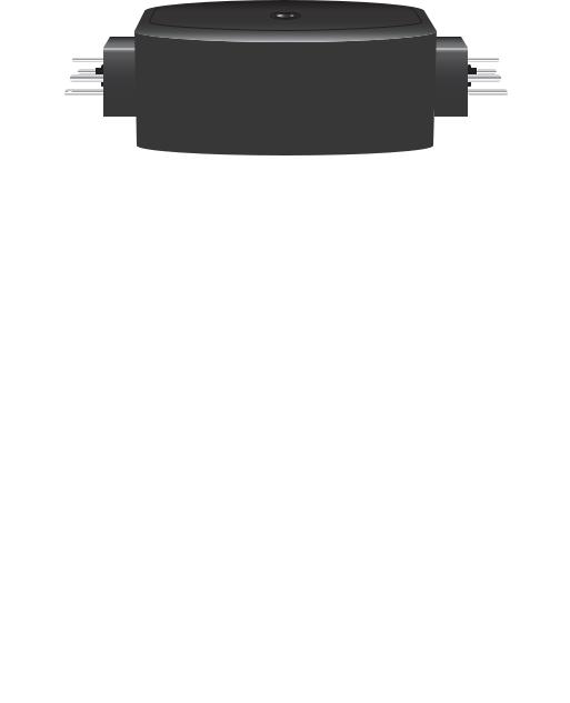
Two versions of the instrument are available, an MDM300 (standard) version and an MDM300 I.S. (intrinsically safe) version. This manual covers the MDM300 I.S. version only. For information about the MDM300 contact your local Michell Instruments’ representative (contact information at www.michell.com). Figure 1 MDM300 I.S.
-
Page 11: Controls And Indicators
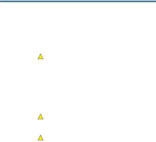
Figure 2 shows the layout of these controls and Table 1 describes their respective operational functions. — I.S. Fig 2.1_V6 Figure 2 User Connections, Controls and Indicators Michell Instruments…
-
Page 12: Table 1 Controls And Indicators
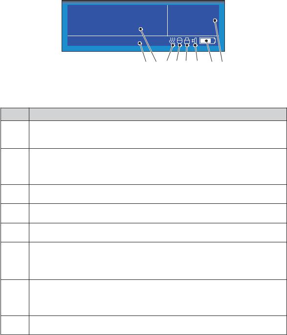
MDM300 I.S. User Manual INTRODUCTION Item Panel Description Function keys. Refer to Section 1.2 for the details of these Front keys. Instrument display, partitioned to show 3 main panels: The primary display shows internal sensor parameters. The secondary display indicates the external sensor Front parameter.
-
Page 13: Function Keys
As the insertion point is shifted to the left, the entry at the former position is deleted. Within any menu or sub-menu level, pressing this ƒ key escapes to the previous menu above the current level. Michell Instruments…
-
Page 14: Instrument Display
MDM300 I.S. User Manual INTRODUCTION Instrument Display The graphics display and the associated function keypad ( Figure 2), form the operator interface of the equipment. Figure 3 shows all the elements of a typical display page after the instrument’s initialization period has completed. Table 2 details the elements of the display: Dewpoint Internal…
-
Page 15: Display Units
, CO or N Dew Point • °C • °F • Relative Humidity (%) Mixing Ratio • g/kg (AIR, USER, H , SF , CO or N To toggle between displayed units, press either the or key. Michell Instruments…
-
Page 16: Status Display Indications
MDM300 I.S. User Manual INTRODUCTION 1.3.2 Status Display Indications ‘ Initializing Internal Sensor’ Initializing Internal Sensor’ This is displayed immediately after the instrument has been powered up, and indicates that the sensor is being heated up to accelerate equilibrium with the moisture in the sample gas.
-
Page 17: Installation
Save all the packing materials for the purpose of returning the instrument for re-calibration or any warranty claims. If the optional carry bag has been ordered it will be located underneath the foam insert, in a cardboard box. Michell Instruments…
-
Page 18: Mdm300 I.s. Accessories
MDM300 I.S. User Manual INSTALLATION MDM300 I.S. Accessories The accessories for the MDM300 I.S. are shown in Figure 6 . Items 1 to 5 are supplied as standard and item 6 is optional. Please check that all the standard components are present after unpacking.
-
Page 19: Figure 6 Accessories
HIGH PRESSURE! High pressure gases are potentially hazardous. Energy stored in these gases can be released suddenly and with extreme force. High pressure systems should be assembled and operated only by people who have been trained in proper safety practices. 97244 Issue 2.2, September 2013 Figure 6 Accessories Michell Instruments…
-
Page 20: Operational Requirements
MDM300 I.S. User Manual INSTALLATION Operational Requirements Operational requirements are as follows: Sample gas flow rate: 0.2 to 0.5 Nl/min (0.5 to 1 scfh) Operating pressure: 0 to 350 barg (0 to 5076 psig) 2.4.1 Environmental Requirements – MDM300 I.S. Instrument Operating temperature range: -20 to +50°C (-4 to +122°F) Humidity:…
-
Page 21: Gas Inlet /Outlet Fittings
Michell Instruments, on request. NOTE: The bonded seals used for the MDM300 I.S. are Dowty part number 400-228-4490-74 (from Michell Instruments, part number MDM300-DS). Michell Instruments…
-
Page 22: Battery Charging
MDM300 I.S. User Manual INSTALLATION Battery Charging WARNING: The battery charger must NOT be connected within the hazardous area. The battery charger socket cover MUST be closed when the product is in use within a hazardous area. The MDM300 I.S. is powered from an internally mounted, rechargeable Nickel Metal Hydride (NiMH) battery.
-
Page 23
If the battery has been damaged then the charger will not begin the fast-charge stage. Please contact Michell Instruments’ service department for advice. Once the charger has finished the fast-charge stage it can be safely disconnected. Switch off the AC power supply, remove the charger unit and close the instrument’s charge connector protection cover. -
Page 24: Operation
MDM300 I.S. User Manual OPERATION OPERATION High pressure gases are potentially dangerous. POSSIBLE INJURY! The tubing, valves and other apparatus attached to this instrument must be adequate for the maximum pressure which will be applied, otherwise physical injury to the operator or bystander is possible. Preparation for Operation The MDM300 I.S.
-
Page 25: Instrument Start-Up
Measurement in progress Measurement in progress message is displayed. After this, depending on the sample conditions, the instrument may continue to respond to the final dew-point for a number of minutes. This is further explained in Section 3.6. Michell Instruments…
-
Page 26: Overall Menu Structure And Operation
MDM300 I.S. User Manual OPERATION Overall Menu Structure and Operation 3.3.1 SET-UP Menu All instrument settings are made from the SET-UP Menu which is accessible from the Main Display by pressing the Enter Enter key. On the first occasion after switch-on the Passcode Entry page will be displayed. Enter the passcode 7316 7316…
-
Page 27: Figure 11 Menu Structure
EXTERNAL ZERO EXTERNAL SPAN PASSCODE USER PRESSURE YEAR MONTH HOUR CONTRAST BRIGHTNESS KEY TONE BL TIMEOUT LANGUAGE PRIMARY DISP POINT MDM300 INFO PAGE LEGEND Enter Key Up/Down Keys Left Right Keys Figure 11 Menu Structure * No longer available Michell Instruments…
-
Page 28: Set-Up Menu Parameters
MDM300 I.S. User Manual OPERATION SET-UP Menu Parameters Follow the instructions in Section 3.3.1 to select the required parameters. 3.4.1 SETTINGS PRIMARY DP AT ATMOS SETTINGS DP/TEMP UNIT °C PRESSURE UNIT Psig GAS TYPE MOL WEIGHT CHART INTERVAL Figure 12 SETTINGS Page Parameter Description Indicates if the primary display sensor is at atmospheric or system…
-
Page 29: Logging
The size of any one log file is limited to 60kb. If the unit is left logging, and the file size exceeds 60kb, then the log file will finish automatically. To ensure that the log file you initiate collects all the data from your test, an Michell Instruments…
-
Page 30: Bluetooth
MDM300 I.S. User Manual OPERATION appropriate sample time should be chosen. The table below can be used as a rough guide: Sample time (sec) Logging duration 3 hours 6 hours 18 hours 36 hours 60 hours 120 hours 240 hours 360 hours 3.4.3 BLUETOOTH…
-
Page 31: 3.4.3.1 Bluetooth Pairing Procedure
. NOTE: The name of With the serial link established, click Configure Configure the COM port allocated, i.e. COM7, will need to be entered when starting the Michell application software. (7) (3) (1) (6) Figure 15 Typical Bluetooth Pairing Sequence Michell Instruments…
-
Page 32: Clock
MDM300 I.S. User Manual OPERATION 3.4.4 CLOCK YEAR CLOCK MONTH HOUR Figure 16 CLOCK Page YEAR CLOCK MONTH HOUR Parameter Description Current year YEAR YEAR Available Input: Range: 00 to 99 YEAR CLOCK MONTH Current month MONTH MONTH HOUR Available Input: Range: 01 to 12 Current day Available Input: Range: 01 to 31 Current hour…
-
Page 33: Info
Figure 18 INFO Page This page contains system information and no changes can be made. Information available: • Firmware number and version • Sensor serial number • Date of sensor calibration next due • Hours that the sensor has been used Michell Instruments…
-
Page 34: Chart Page
MDM300 I.S. User Manual OPERATION 3.4.7 CHART Page At any time while the Main Display is indicating internal sensor parameters, a graphical display of the output can be obtained by pressing the key from the Main Display. The chart can be reset at any time by pressing the Enter Enter key.
-
Page 35: Logs Page
Logging interval • Current date in YYMMDD format • T# T# Current time in HHMMSS format NOTE: The chart and datalogging are independent functions; therefore the parameter displayed on the chart may not necessarily reflect what is being logged. Michell Instruments…
-
Page 36: 3.4.10 Calibration
MDM300 I.S. User Manual OPERATION 3.4.10 CALIBRATION Input passcode for setup menu WARNING: These procedures require the use of specialized test equipment and calibration adjustments should only be 0 0 0 carried out by qualified personnel. POINT MDM300 CALIBRATION -100 -100.0 -100.0 -90.0…
-
Page 37: Default Parameters
Current UK time & date CONTRAST BRIGHTNESS Section 3.4.5, Figure 17 KEYTONE BL TIME-OUT LANGUAGE PRIMARY DISP INTERN CALIBRATION & INFO CALIBRATION & INFO Section 3.4.10 & Section 6 Default values not applicable Table 9 MDM300 I.S. Default Parameters Michell Instruments…
-
Page 38: Guide To Measurement And Sampling
For the most basic measurement it is recommended to have a flow meter (0 to 1 l/min), and at least one metering valve. A number of sampling kits are available from Michell Instruments: • The Easi-fit sample kit is a low cost sampling system consisting of 2 metering valves and a flow meter which is suitable for many applications.
-
Page 39: Measuring At Atmospheric Or System Pressure
The metering valve on the inlet should be used to control the sample flow. To measure at system pressure the metering valve on the instrument inlet should be fully open. The metering valve on the outlet should be used to control the sample flow. Michell Instruments…
-
Page 40: Measurement Guide
MDM300 I.S. User Manual OPERATION 3.6.2 Measurement Guide Follow procedure A and note the result. Turn the instrument off. If you wish to measure at sample pressure then use the Michell Humidity Calculator (http://www.michell.com/uk/downloads/humidity_calculator. msi) to convert this result back to the equivalent at your sample pressure. Using this converted result, and the table below, find the appropriate procedure to measure your sample.
-
Page 41
Once ‘ Measurement in progress’ Measurement in progress’ has disappeared, the instrument is close to the final dew point. Depending on the conditions, it may continue to respond for a number of minutes before tracking the measured dew point. Michell Instruments… -
Page 42: Conditional Sensor Purge
15 seconds or the battery may be damaged. NOTE: Michell Instruments will replace the older FW 7219 charger with the new Cell Con model free of charge. The Cell Con will re-charge batteries which have completely discharged.
-
Page 43: Good Measurement Practice
The table below offers an approximate guide to the times taken for the instrument to stabilize at a given dew point (from a starting point of 10°Cdp ambient): Target Dew Point (°C) T100 response time from ambient (hours) -100 Michell Instruments…
-
Page 44: Sampling Hints
MDM300 I.S. User Manual GOOD MEASUREMENT PRACTICE Sampling Hints Ensuring reliable and accurate moisture measurements requires the correct sampling techniques, and a basic understanding of how water vapor behaves. This section aims to explain the common mistakes and how to avoid them. Sampling Materials –…
-
Page 45
Theoretically flow rate has no direct effect on the measured moisture content, but in practice it can have unanticipated effects on response speed and accuracy. An inadequate flow rate may: Michell Instruments… -
Page 46
MDM300 I.S. User Manual GOOD MEASUREMENT PRACTICE • Accentuate adsorption and desorption effects on the gas passing through the sampling system. • Allow pockets of wet gas to remain undisturbed in a complex sampling system, which will then gradually be released into the sample flow. •… -
Page 47: Application Software
These can be downloaded to a specific location by right clicking, and selecting ‘ download download ’. A context sensitive help file provides further details on the use of the application software. Figure 26 Typical Application Software Screen Michell Instruments…
-
Page 48: Calibration
If these facilities do not exist it is recommended that the instrument be returned to the manufacturer, Michell Instruments Ltd., or one of the approved agents. A calibration certificate bearing a seven point calibration is issued with each instrument.
-
Page 49: Calibration Method
A set of results similar to that shown below could be generated over the calibration range of the instrument. Stabilize Stabilize DP REF MDM300 I.S. DP REF MDM300 I.S. Time Time °C Rdg °C °C Rdg °C (Hours) (Hours) -100 -99.8 -30.1 -79.7 -19.9 -59.8 -49.8 -39.9 Table 11 Example Of Calibration Run Readings Michell Instruments…
-
Page 50: Calibration Correction Method
MDM300 I.S. User Manual CALIBRATION Calibration Correction Method NOTE: Any logging procedure currently in operation must be cancelled before the calibration procedures can be entered. CALIBRATION CALIBRATION To enter the CALIBRATION Menu page, highlight from the SET-UP Menu by using the or keys and press the Enter Enter key.
-
Page 51: Shipping
Create a packing list detailing all equipment contained in the box, place it inside the box and seal the box. Before disconnecting the MDM300 I.S. from the gas line it is essential to vent the system to atmospheric pressure, otherwise severe injury could result. Figure 29 Instrument Packing Details Michell Instruments…
-
Page 52
MDM300 I.S. User Manual APPENDIX A Appendix A Technical Specifications 97213 Issue 6.2, August 2021… -
Page 53: Appendix A Technical Specifications
1/8” NPT female (other options available) Gas Wetted Materials AISI 316L stainless steel, PTFE Seal, Borosilicate glass, ceramic Outline Dimensions 218 x 170 x 90mm (8.6 x 6.7 x 3.5ft) (d x w x h) Weight 1.5kg (3.3lbs) Michell Instruments…
-
Page 54: Dimensions
MDM300 I.S. User Manual APPENDIX A Capacity: 8Mb Data Logging Log interval: 5…60 sec Maximum log file size: 60kb Communications (Wireless) Bluetooth range up to 5m (16ft) (Version 2.0) Languages English, German, Spanish, French, Italian, Portuguese Hazardous Area Certification Certification Codes See Appendix C * The end user has a responsibility to ensure that when installed in the Hazardous Area, the system is compliant with relevant local and international installation Standards for the use of equipment in explosive atmospheres.
-
Page 55
MDM300 I.S. User Manual APPENDIX B Appendix B Datalog Status Display Michell Instruments… -
Page 56: Appendix B Datalog Status Display
Figure 36 . Bit 1 is the least significant bit. The four most significant bits 13…16 are for Michell Instruments’ service use and so the first character in any MDM300 I.S. ST display will always read 0.
-
Page 57: Table 14 Status Register Flags
External sensor error’ and bit 6 set ‘ Measurement in progress’ Measurement in progress’ Therefore, at the time that these log points were taken, the external sensor was out of range and the internal dew point was not stable. Michell Instruments…
-
Page 58
MDM300 I.S. User Manual APPENDIX C Appendix C Hazardous Area Certification 97213 Issue 6.2, August 2021… -
Page 59: Appendix C Hazardous Area Certification
Class I, Zone 0, AEx ia IIC T4 Ga Ex ia IIC T4 Ga Ta=-20°C…+50°C Global Certificates/Approvals ATEX SGS Baseefa 06ATEX0330X IECEx IECEX BAS 06.0090XX UKCA BAS 21UKEX0015X LR1507-5 These certificates can be viewed or downloaded from our websites at: www.processsensing.com & www.michell.com Michell Instruments…
-
Page 60: Input Terminal Parameters
Maintenance and servicing of the product must only be carried out by suitably trained personnel or returned to an approved Michell Instruments Service Center. 97213 Issue 6.2, August 2021…
-
Page 61
MDM300 I.S. User Manual APPENDIX D Appendix D FCC Declaration Michell Instruments… -
Page 62: Appendix Dfcc Declaration
Règlement canadien sur les interférences radio. Ce produit numérique de classe B est conforme à la norme NMB-003, CISPR 22: 1997. Signed for, and on behalf of, Michell Instruments Ltd. Andrew M.V. Stokes, Technical Director Issue date: 05/2011 97213 Issue 6.2, August 2021…
-
Page 63
MDM300 I.S. User Manual APPENDIX E Appendix E Quality, Recycling & Warranty Information Michell Instruments… -
Page 64: Appendix E Quality, Recycling & Warranty Information
MDM300 I.S. User Manual APPENDIX E Appendix E Quality, Recycling & Warranty Information Michell Instruments is dedicated to complying to all relevant legislation and directives. Full information can be found on our website at: www.michell.com/compliance This page contains information on the following directives: •…
-
Page 65
MDM300 I.S. User Manual APPENDIX F Appendix F Return Document & Decontamination Declaration Michell Instruments… -
Page 66: Appendix F Return Document & Decontamination Declaration
Has the equipment been cleaned and decontaminated? NOT NECESSARY Michell Instruments will not accept instruments that have been exposed to toxins, radio-activity or bio-hazardous materials. For most applications involving solvents, acidic, basic, flammable or toxic gases a simple purge with dry gas (dew point <-30°C) over 24 hours should be sufficient to decontaminate the unit prior to return.
-
Page 67
MDM300 I.S. User Manual NOTES: Michell Instruments… -
Page 68
www.ProcessSensing.com http://www.michell.com…
![]()
MDM300 I.S.
Advanced Dew-Point Hygrometer
User’s Manual


 -I.S.
-I.S.


97213 Issue 5
October 2017

Please fill out the form(s) below for each instrument that has been purchased.
Use this information when contacting Michell Instruments for service purposes.
Hygrometer
Code
Serial Number
Invoice Date
Location of Instrument
Tag No
Hygrometer
Code
Serial Number
Invoice Date
Location of Instrument
Tag No
Hygrometer
Code
Serial Number
Invoice Date
Location of Instrument
Tag No


 -I.S.
-I.S.


MDM300 I.S.
Advanced Dew-Point Hygrometer (for use in hazardous areas)
For Michell Instruments’ contact information please go to www.michell.com
© 2017 Michell Instruments
This document is the property of Michell Instruments Ltd. and may not be copied or otherwise reproduced, communicated in any way to third parties, nor stored in any Data Processing System without the express written authorization of Michell Instruments Ltd.
|
MDM300 I.S. User’s Manual |
|||
|
Contents |
|||
|
Safety ………………………………………………………………………………………………………………. |
vii |
||
|
Electrical Safety …………………………………………………………………………………………… |
vii |
||
|
Pressure Safety…………………………………………………………………………………………….. |
vii |
||
|
Toxic Materials ……………………………………………………………………………………………… |
vii |
||
|
Repair and Maintenance …………………………………………………………………………………. |
vii |
||
|
Calibration…………………………………………………………………………………………………… |
vii |
||
|
Safety Conformity …………………………………………………………………………………………. |
vii |
||
|
Abbreviations |
viii |
||
|
Warnings ………………………………………………………………………………………………………….. |
viii |
||
|
1 |
INTRODUCTION …………………………………………………………………………………… |
1 |
|
|
1.1 |
Controls ……………………………………………………………………………and Indicators |
3 |
|
|
1.2 |
Function ………………………………………………………………………………………..Keys |
5 |
|
|
1.2.1 |
……………………………………………………………………………………….. |
5 |
|
|
1.2.2 |
………………………………………………………………… |
5 |
|
|
1.2.3 |
………………………………………………………………………………….. |
5 |
|
|
1.2.4 |
………………………………………………………………………… |
5 |
|
|
1.3 |
Instrument …………………………………………………………………………………Display |
6 |
|
|
1.3.1 |
……………………………………………………………………………………. |
7 |
|
|
1.3.2 |
…………………………………………………………………… |
8 |
|
|
2 |
INSTALLATION …………………………………………………………………………………….. |
9 |
|
|
2.1 |
Safety…………………………………………………………………………………………………. |
9 |
|
|
2.2 |
Unpacking ………………………………………………………………………..the Instrument |
9 |
|
|
2.3 |
MDM300 ……………………………………………………………………….I.S. Accessories |
10 |
|
|
2.4 |
Operational ………………………………………………………………………Requirements |
12 |
|
|
2.4.1 |
………………………….. |
12 |
|
|
2.4.2 |
…………………………………………………………. |
12 |
|
|
2.5 |
Instrument …………………………………………………………………..Gas Connections |
12 |
|
|
2.5.1 |
………………………………………………………………….. |
13 |
|
|
2.6 |
Connect ……………………………………………………………………….External Sensors |
14 |
|
|
2.6.1 |
………………………………………………………… |
15 |
|
|
2.6.2 |
…………………………………………………………………….. |
15 |
|
|
2.7 |
Battery ………………………………………………………………………………….Charging |
16 |
|
|
3 |
OPERATION ………………………………………………………………………………………. |
18 |
|
|
3.1 |
Preparation ……………………………………………………………………….for Operation |
18 |
|
|
3.2 |
Instrument …………………………………………………………………………….Start-Up |
19 |
|
|
3.3 |
Overall ……………………………………………………….Menu Structure and Operation |
20 |
|
|
3.3.1 |
…………………………………………………………………………………. |
20 |
|
|
3.3.2 |
……………………………………………………………………………………. |
20 |
|
|
3.4 |
SET ……………………………………………………………………….-UP Menu Parameters |
22 |
|
|
3.4.1 |
…………………………………………………………………………………….. |
22 |
|
|
3.4.2 |
……………………………………………………………………………………… |
23 |
|
|
3.4.3 |
………………………………………………………………………………….. |
24 |
|
|
3.4.3.1 …………………………………………………………. |
25 |
||
|
3.4.4 |
…………………………………………………………… |
26 |
|
|
3.4.5 |
…………………………………………………………………………………………. |
27 |
|
|
3.4.6 |
…………………………………………………………………………………………….. |
28 |
|
|
3.4.7 |
……………………………………………………………………………………………. |
29 |
|
|
3.4.8 |
………………………………………………………………………………….. |
29 |
|
|
3.4.9 |
……………………………………………………………………………… |
30 |
|
|
3.4.10 |
……………………………………………………………………………………. |
30 |
|
|
3.4.11 |
………………………………………………………………………………… |
31 |
|
|
3.5 |
Default ……………………………………………………………………………….Parameters |
32 |
|
iv |
97213 Issue 5, October 2017 |

MDM300 I.S. User’s Manual
|
3.6 |
Guide to Measurement and Sampling……………………………………………………….. |
33 |
|
|
3.6.1 |
Measuring at Atmospheric or System Pressure ………………………………………. |
34 |
|
|
3.6.2 |
Measurement Guide ………………………………………………………………………… |
35 |
|
|
3.6.3 |
Conditional Sensor Purge………………………………………………………………….. |
37 |
|
|
3.7 |
Battery Management ……………………………………………………………………………. |
37 |
|
|
3.7.1 |
Battery Troubleshooting……………………………………………………………………. |
37 |
|
|
4 |
GOOD MEASUREMENT PRACTICE …………………………………………………………… |
38 |
|
|
4.1 |
Sampling Hints ……………………………………………………………………………………. |
39 |
|
|
5 |
APPLICATION SOFTWARE …………………………………………………………………….. |
42 |
|
|
6 |
CALIBRATION…………………………………………………………………………………….. |
43 |
|
|
6.1 |
Traceability ………………………………………………………………………………………… |
43 |
|
|
6.2 |
Calibration Method ………………………………………………………………………………. |
44 |
|
|
6.3 |
Calibration Correction Method ………………………………………………………………… |
45 |
|
|
7 |
SHIPPING …………………………………………………………………………………………. |
46 |
Appendices
|
Appendix A |
Technical Specifications…………………………………………………………………… |
48 |
|
|
A.1 |
Dimensions ……………………………………………………………………… |
49 |
|
|
Appendix B |
Datalog Status Display ……………………………………………………………………. |
51 |
|
|
Appendix C |
Hazardous Area Certification ……………………………………………………………. |
54 |
|
|
C.1 |
Product Standards …………………………………………………………….. |
54 |
|
|
C.2 |
Product Certification ………………………………………………………….. |
54 |
|
|
C.3 |
Global Certificates/Approvals ……………………………………………….. |
54 |
|
|
C.4 |
Input Terminal Parameters …………………………………………………. |
54 |
|
|
C.5 |
Special Conditions of Use ……………………………………………………. |
55 |
|
|
C.6 |
Maintenance and Installation……………………………………………….. |
55 |
|
|
Appendix D |
FCC Declaration…………………………………………………………………………….. |
57 |
|
|
Appendix E |
Quality, Recycling & Warranty Information…………………………………………… |
59 |
|
|
Appendix F |
Return Document & Decontamination Declaration…………………………………. |
61 |

|
MDM300 I.S. User’s Manual |
|||
|
Figures |
|||
|
Figure 1 |
MDM300 I.S. Advanced Dew-Point Hygrometer……………………………………… |
2 |
|
|
Figure 2 |
User Connections, Controls and Indicators……………………………………………. |
3 |
|
|
Figure 3 |
Instrument Display …………………………………………………………………………. |
6 |
|
|
Figure 4 |
Packing Method……………………………………………………………………………… |
9 |
|
|
Figure 5 |
Gas Port Adaptors ………………………………………………………………………… |
10 |
|
|
Figure 6 |
Accessories …………………………………………………………………………………. |
11 |
|
|
Figure 7 |
Bonded Seal Fitting ………………………………………………………………………. |
13 |
|
|
Figure 8 |
Gas Coupling Examples for Atmospheric Pressure Measurement………………. |
13 |
|
|
Figure 9 |
MDM300 I.S. Remote Sensor Interface………………………………………………. |
14 |
|
|
Figure 10 |
External Sensor Connection…………………………………………………………….. |
14 |
|
|
Figure 11 |
Typical External Dew-Point Display……………………………………………………. |
15 |
|
|
Figure 12 |
Battery Charger Connection ……………………………………………………………. |
16 |
|
|
Figure 13 |
Start-Up Sequence ……………………………………………………………………….. |
19 |
|
|
Figure 14 |
Menu Structure ……………………………………………………………………………. |
21 |
|
|
Figure 15 |
SETTINGS Page……………………………………………………………………………. |
22 |
|
|
Figure 16 |
LOGGING Page…………………………………………………………………………….. |
23 |
|
|
Figure 17 |
BLUETOOTH Page ………………………………………………………………………… |
24 |
|
|
Figure 18 |
Typical Bluetooth Pairing Sequence…………………………………………………… |
25 |
|
|
Figure 19 |
EXTERNAL SET-UP Page…………………………………………………………………. |
26 |
|
|
Figure 20 |
CLOCK Page………………………………………………………………………………… |
27 |
|
|
Figure 21 |
HMI Page……………………………………………………………………………………. |
28 |
|
|
Figure 22 |
INFO Page ………………………………………………………………………………….. |
29 |
|
|
Figure 23 |
CHART Page………………………………………………………………………………… |
29 |
|
|
Figure 24 |
LOG FILES Page …………………………………………………………………………… |
30 |
|
|
Figure 25 |
LOGS Page………………………………………………………………………………….. |
30 |
|
|
Figure 26 |
CALIBRATION Page ………………………………………………………………………. |
31 |
|
|
Figure 27 |
Easi-Fit Sample Kit |
MDM300 Panel-Mount Sampling System ……… |
33 |
|
Figure 28 |
Large and Small Orifice Fitting…………………………………………………………. |
34 |
|
|
Figure 29 |
Typical Application Software Screen ………………………………………………….. |
42 |
|
|
Figure 30 |
Typical 7-point Calibration Certificate ………………………………………………… |
43 |
|
|
Figure 31 |
Calibration Menu Page …………………………………………………………………… |
45 |
|
|
Figure 34 |
Instrument Packing Details……………………………………………………………… |
46 |
|
|
Figure 35 |
Dimensions — MDM300 I.S. ……………………………………………………………… |
49 |
|
|
Figure 36 |
Current Datalog File Display ……………………………………………………………. |
51 |
|
|
Figure 37 |
MDM300 I.S. Status Register…………………………………………………………… |
51 |
|
|
Figure 38 |
MDM300 I.S. Status Register (Hex 28) ………………………………………………. |
51 |
|
Tables |
||
|
Table 1 |
Controls and Indicators…………………………………………………………………….. |
4 |
|
Table 2 |
Instrument Display Descriptions …………………………………………………………. |
6 |
|
Table 3 |
Adaptor Fittings…………………………………………………………………………….. |
12 |
|
Table 4 |
SETTINGS Parameters ……………………………………………………………………. |
22 |
|
Table 5 |
LOGGING Parameters …………………………………………………………………….. |
23 |
|
Table 6 |
BLUETOOTH Parameters …………………………………………………………………. |
24 |
|
Table 7 |
EXTERNAL Sensor Parameters ………………………………………………………….. |
26 |
|
Table 8 |
CLOCK Parameters ………………………………………………………………………… |
27 |
|
Table 9 |
HMI Parameters ……………………………………………………………………………. |
28 |
|
Table 10 |
MDM300 I.S. Default Parameters ………………………………………………………. |
32 |
|
Table 11 |
MDM300 I.S. Measurement Procedures ………………………………………………. |
35 |
|
Table 12 |
Example Of Calibration Run Readings…………………………………………………. |
44 |
|
Table 13 |
Status Register Flags ……………………………………………………………………… |
52 |
|
vi |
97213 Issue 5, October 2017 |
MDM300 I.S. User’s Manual
Safety
The manufacturer has designed this equipment to be safe when operated using the procedures detailed in this manual. The user must not use this equipment for any other purpose than that stated. Do not apply values greater than the maximum value stated.
This manual contains operating and safety instructions, which must be followed to ensure the safe operation and to maintain the equipment in a safe condition. The safety instructions are either warnings or cautions issued to protect the user and the equipment from injury or damage. Use competent personnel using good engineering practice for all procedures in this manual.
The instrument is designed to be completely safe when used with options and accessories supplied by the manufacturer for use with the instrument. The instrument is powered by an internally mounted rechargeable battery — this battery should never be allowed to fully discharge. The input power supply voltage limits for the battery charger supplied with the instrument are 100 to 240 V AC, 50/60 Hz.
NOTE: No other battery charger unit, other than that supplied with the instrument should be used.
NOTE: Do not allow the battery to fully discharge.
DO NOT permit pressures greater than the safe working pressure to be applied to the instrument. The specified safe working pressure (SWP), for this instrument is 350 barg (5076 psig).
The use of hazardous materials in the construction of this instrument has been minimized. During normal operation it is not possible for the user to come into contact with any hazardous substance which might be employed in the construction of the instrument. Care should, however, be exercised during maintenance and the disposal of certain parts.
Repair and Maintenance
The instrument must be maintained either by the manufacturer or an accredited service agent. Refer to www.michell.com for details of Michell Instruments’ worldwide offices contact information.
Calibration
The recommended calibration interval for the MDM300 I.S. is 12 months. The instrument should be returned to the manufacturer, Michell Instruments Ltd., or one of their accredited service agents for re-calibration.
Safety Conformity
This product meets the essential protection requirements of the relevant EU directives. Further details of applied standards may be found in Appendix F.

MDM300 I.S. User’s Manual
Abbreviations
The following abbreviations are used in this manual:
|
AC |
alternating current |
|
atm |
pressure unit (atmosphere) |
|
barg |
pressure unit (=100 kP or 0.987 atm) gauge |
|
bara |
bar absolute |
|
°C |
degrees Celsius |
|
°F |
degrees Fahrenheit |
|
K |
Kelvin (absolute temperature) |
|
COM |
common |
|
DC |
direct current |
|
ft |
foot (feet) |
|
Hz |
Hertz |
|
kg |
kilogram(s) |
|
lb |
pound |
|
Nl/min |
liters per minute |
|
m |
meter(s) |
|
mA |
milliampere |
|
Mb |
megabytes |
|
max |
maximum |
|
min |
minute(s) |
|
mm |
millimeter(s) |
|
MPa |
megapascal |
|
No. |
number |
|
PIN |
personal identification number |
|
ppmV |
parts per million (by volume) |
|
ppmW |
parts per million (by weight) |
|
psig |
pounds per square inch |
|
scfh |
standard cubic feet per hour |
|
SWP |
safe working pressure |
|
sec |
second(s) |
|
V |
volts |
Warnings
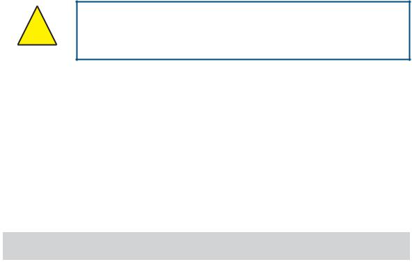
The following general warning listed below is applicable to this instrument. It is repeated in the text in the appropriate locations.
Where this hazard warning symbol appears in the following sections it is used to indicate areas where potentially hazardous operations need to be carried out.
|
viii |
97213 Issue 5, October 2017 |
|
MDM300 I.S. User’s Manual |
INTRODUCTION |
1 INTRODUCTION
The MDM300 I.S. Advanced Dew-Point Hygrometer is a portable instrument designed for online measurement of moisture content in non-corrosive gases in hazardous areas, over an operational range of -100 to +20°C (-148 to +68°F).
The instrument is independently assessed and certificated as being intrinsically safe and fully compatible with safe operation within defined Zone 0 hazardous areas.
The instrument is contained within a steel fiber-loaded high-impact polyamide 6 case, sealed to IP66 / NEMA4 standard and is powered by an internally mounted Nickel Metal Hydride (NiMH) battery, designed to typically provide 24 hours continuous use between charges. Continuous battery charge status indication is provided. Additional battery status information is provided by a battery indicator icon, in addition to a warning beep and Shutdown Mode.
The MDM300 I.S. is fitted with an internally mounted ceramic sensor, which is enhanced for a quicker response to dew points as dry as -75°Cdp (-103°Fdp).
The MDM300 I.S. can also be used to read the dew-point signal from a Michell Instruments’ Easidew I.S. transmitter. To do this, the MDM300 I.S. Remote Sensor Interface is used to connect to the Easidew I.S. transmitter.
No other sensor can be connected to the MDM300 I.S.
A graphical display presents the dew-point data in large format characters and simultaneously provides a primary display of real time dew-point readings and a secondary display, in smaller characters, for the external sensor input. If no external input is programmed, gas temperature (measured by the internal sensor) is displayed by default.
A fully programmable, real-time, datalogging facility is provided which has an internal memory capacity of 8Mb, capable of storing up to 10,000 logs per file (typically giving a maximum of 64 log files).
A Bluetooth, wireless, communication system is provided, giving access to a dedicated, PC based, MDM300 I.S. Software Application Package which provides the facility for handling the logged data files and uploading and downloading instrument parameters.
A user-friendly operator interface provides easy access to all levels of the instrument’s functionality.
An easy-to-follow calibration routine is built into the instrument’s software.
|
INTRODUCTION |
MDM300 I.S. User’s Manual |
Two versions of the instrument are available, an MDM300 (standard) version and an MDM300 I.S. (intrinsically safe) version.
This manual covers the MDM300 I.S. version only.
For information about the MDM300 contact your local Michell Instruments’ representative (contact information at www.michell.com).


 -I.S.
-I.S.


Figure 1 MDM300 I.S. Advanced Dew-Point Hygrometer
(for use in hazardous areas)
|
2 |
97213 Issue 5, October 2017 |
![]()
|
MDM300 I.S. User’s Manual |
INTRODUCTION |
1.1Controls and Indicators
The controls and indicators associated with the MDM300 I.S. instrument are located on the front panel of the instrument.
Connections to the MDM300 I.S. dew-point hygrometer, comprising the gas ports, battery charger input connector and input connector for the external sensor are all made to the top panel.
Figure 2 shows the layout of these controls and Table 1 describes their respective operational functions.
2


 — I.S.
1
.S.I- 

|
7 |
6 |
5 |
4 |
3 |
Figure 2 User Connections, Controls and Indicators

|
INTRODUCTION |
MDM300 I.S. User’s Manual |
|||
|
Item |
Panel |
Description |
||
|
1 |
Front |
Function keys. Refer to Section 1.2 for the details of these |
||
|
keys. |
||||
|
Instrument display, partitioned to show 3 main panels: |
||||
|
The primary display shows internal sensor parameters. |
||||
|
2 |
Front |
The |
secondary display indicates the external sensor |
|
|
parameter. |
||||
|
The status display area shows icons representing battery |
||||
|
charge state, initialization in progress, data logging in |
||||
|
progress, keyboard lock status and keyboard beep status. |
||||
|
Instrument ON/OFF switch. |
||||
|
3 |
Top |
NOTE: The instrument does not need be switched ON |
||
|
in order to charge the internal NiMH battery. |
||||
|
4 |
Top |
Gas Output port. Refer to Section 2.5. |
||
|
5 |
Top |
Gas Input port. Refer to Section 2.5. |
||
|
Analog input connector for external sensor. |
||||
|
By default, this signal is displayed in the secondary display |
||||
|
area but may be configured to be displayed as the primary |
||||
|
display. |
||||
|
6 |
Top |
If no external input is selected, the internal sensor |
||
|
temperature is shown, on the secondary display, by default |
||||
|
(refer to Section 3.4.6). |
||||
|
NOTE: The hinged rubber protection cover should be |
||||
|
kept closed when the connector is not in use. |
||||
|
Socket for connection of battery charger (located behind |
||||
|
secured cover). |
||||
|
Connection to the battery charger should |
||||
|
! |
always be made in a safe area — never in a |
|||
|
7 |
Top |
hazardous area environment |
||
|
The secured cover should be kept screwed on when the |
||||
|
connector is not in use. |
||||
|
! |
ONLY USE THE CHARGER PROVIDED |
|||
|
! |
Never allow the battery to fully discharge |
|||
Table 1 Controls and Indicators
|
4 |
97213 Issue 5, October 2017 |
|
MDM300 I.S. User’s Manual |
INTRODUCTION |
1.2Function Keys
The function keys, located on the front panel, are used to select operations from the menus and to select and enter parameter variables within those menu levels.
The function key described is shaded darker and the operation of the keys is as follows:
1.2.1Enter Key
The Enter key is used within the menus to highlight and select options and to accept entered values.
Operation of this key from the Main Display causes the Passcode entry page (for entry to the SET-UP Menu) to be displayed.
1.2.2Up () and Down () Keys
Within the SET-UP Menu and sub-menus these and keys are used to scroll down and highlight options.
Within sub-menu levels requiring the entry of alpha numeric values, these keys are used to change the values. Pressing the key once increases or decreases the selected field by one step. Pressing and holding the key will cause the selected field to be continuously increased or decreased until the key is released.
1.2.3Right () Key
Within sub-menu levels requiring the entry of alpha numeric values, this key is used to shift the insertion point right in the file name entry field.
From the Main Display, pressing this key moves to the Chart
Page.
From the Chart Page, pressing this key moves to the Logging
Pages.
1.2.4Left () / Escape Key
Within sub-menu levels requiring the entry of alpha numeric values, this key is used to shift the insertion point left in the file name entry field. As the insertion point is shifted to the left, the entry at the former position is deleted.
Within any menu or sub-menu level, pressing this key escapes to the previous menu above the current level.
|
INTRODUCTION |
MDM300 I.S. User’s Manual |
1.3Instrument Display
The graphics display and the associated function keypad (Figure 2), form the operator interface of the equipment. Figure 3 shows all the elements of a typical display page after the instrument’s initialization period has completed.
Table 2 details the elements of the display:
|
8 |
7 |
6 |
5 |
4 |
3 |
2 |
1 |
Figure 3 Instrument Display
Item Description
Secondary display
1Shows reading from external sensor, if configured; or internal temperature if external sensor is not configured (refer to Section 3.4.6).
Battery charge indicator icon
2Flashes when the battery needs charging. A warning beep sounds when the battery charge level is critical — followed immediately by Shutdown Mode.
NOTE: The icon becomes animated when the charger is connected.
3Keyboard beep indicator
Indicates that the keyboard beep is switched on.
4Keyboard lock indicator
Indicates that the keyboard is locked.
5Datalog status indicator
Indicates that logging is enabled and running.
Sensor initializing indicator
6Indicates that the initialization process is in progress and that the sensor heating is on. The presence of this symbol is accompanied by Initializing internal sensor status message.
Primary display
7During normal operation, the internal sensor readings are shown in the primary display. If the external sensor has been configured then this reading can be shown in this display (refer to Section 3.4.6).
8Status message display area
Displays status and error messages.
Table 2 Instrument Display Descriptions
|
6 |
97213 Issue 5, October 2017 |
|
MDM300 I.S. User’s Manual |
INTRODUCTION |
1.3.1Display Units
The instrument can display the measured reading in the following units:
Absolute Humidity
•lb/MMscf
•g/m3
•g/m3 NG
Moisture Content
•ppmV NG
•ppmV
•ppmW (AIR, USER, H2, SF6, CO2 or N2)
Dew Point
•°C
•°F
•K
Relative Humidity (%)
Mixing Ratio
•g/kg (AIR, USER, H2, SF6, CO2 or N2)
To toggle between displayed units, press either the or key.
|
INTRODUCTION |
MDM300 I.S. User’s Manual |
1.3.2Status Display Indications
‘Initializing Internal Sensor’
This is displayed immediately after the instrument has been powered up, and indicates that the sensor is being heated up to accelerate equilibrium with the moisture in the sample gas. This has the effect of drying the sensor out, and results in the ‘undershoot’ seen in the first stage of the measurement process.
‘Measurement in Progress’
This is displayed after the sensor initialization has finished, and indicates that the sensor is running through the following initial measurement procedure:
1.Undershooting the dew-point
2.Making a first estimate
3.Running a QRA (Quick Response Algorithm), if necessary
Once the message has disappeared, this indicates that the instrument has finished its accelerated approach to the actual dew point. Depending on the conditions, it may continue to respond for a number of minutes more, before settling on (or tracking) the actual measured dew point.
Other Status Display Indications
|
Internal sensor |
Dew-point reading out of range (> +30 / < -120°C) |
||
|
error |
|||
|
Internal thermistor |
Sensor internal temperature reading out of range (> +100 / |
||
|
< -40°C) or |
|||
|
error |
Thermistor fault |
||
|
External sensor |
External Sensor Input out of range (< 4 mA / > 20 mA) |
||
|
error |
|||
|
Battery low |
Battery level low — recharge as soon as possible |
||
|
Battery |
low |
— |
Battery level critical — recharge immediately |
|
recharge now |
|||
|
Log finished |
Log file has reached the maximum of 10,000 logs and logging has |
||
|
been stopped |
|||
|
Internal sensor not |
Could not detect internal sensor on power up |
||
|
found |
|||
|
Default CONFIG file |
Config. file missing, new file created and default settings used |
||
|
used |
|
8 |
97213 Issue 5, October 2017 |
|
MDM300 I.S. User’s Manual |
INSTALLATION |
2 INSTALLATION
2.1Safety
It is essential that the installation of the electrical and ! gas supplies to this instrument be undertaken by qualified
personnel.
2.2Unpacking the Instrument
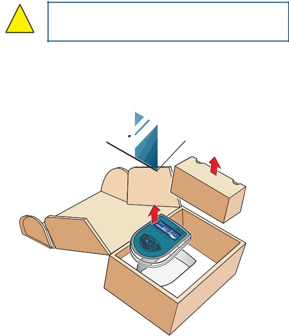
The MDM300 I.S. instrument is packed into a standard box and the method of unpacking is shown below:
|
I |
. |
Hygrometer |
|||
|
.S |
|||||
|
-PointManual |
|||||
|
MDM300 |
|||||
|
Dew |
|||||
|
Advanced |
User’s |
4 |
|||
|
3 |
Figure 4 Packing Method
1.Open the box (1) and unpack carefully.
2.Remove the MDM300 I.S. (2), the user’s manual (3) and the accessories box (4).
3.Save all the packing materials for the purpose of returning the instrument for re-calibration or any warranty claims.
4.If the optional carry bag has been ordered it will be located underneath the foam insert, in a cardboard box.
|
INSTALLATION |
MDM300 I.S. User’s Manual |
2.3MDM300 I.S. Accessories
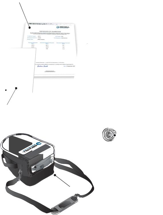
The accessories for the MDM300 I.S. are shown in Figure 6. Items 1 to 7 are supplied as standard and item 8 is optional. Please check that all the standard components are present after unpacking. Report any shortages immediately.
1.Calibration certificate
2.User’s manual
3.Charger unit
4.Country specific mains lead
5.Gas Input/Output port adaptors
(three provided — two fitted to the instrument — see Figure 5)
6.Application Software CD
7.Quick-start card
8.Carrying case — made from anti-static materials suitable for use in hazardous areas (optional)
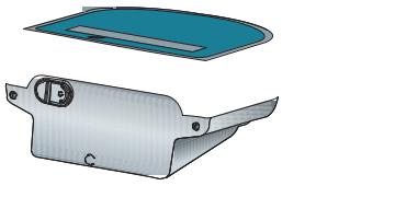
Three gas port adaptors are provided, two with a large bore orifice and one with a small bore orifice. Depending upon configuration, this permits the instrument to be run at either system pressure or atmospheric pressure and facilitates the connection of external flow monitoring and control.
NOTE: On delivery the two large orifice adaptors are fitted into the instrument’s gas ports (1 and 2) as shown in Figure 5. One small orifice adaptor is provided as a loose spare in the accessory pack (see Section 2.5).
.S.I —
Small orifice
Large orifice
21
Figure 5 Gas Port Adaptors
|
10 |
97213 Issue 5, October 2017 |
|
MDM300 I.S. User’s Manual |
INSTALLATION |
1
MDM300 & MDM300 I.S. Quick Start Guide
Typical MDM300 Sampling Arrangement
SAMPLE FLOW
 1
1
 2
2
3
4
VENT
1 Coalescing Filter
2Particulate Filter
3Inlet Flow Control Valve
4Outlet Flow Control Valve
HIGH PRESSURE! High pressure gases are potentially hazardous. Energy stored in these
! JDVHV FDQ EH UHOHDVHG VXGGHQO DQG ZLWK H[WUHPH IRUFH +LJK SUHVVXUH VVWHPV VKRXOG EH
DVVHPEOHG DQG RSHUDWHG RQO E SHRSOH ZKR KDYH EHHQ WUDLQHG LQ SURSHU VDIHW SUDFWLFHV
97244 Issue 02, July 2011
7
2
Hygrometer
. -I.S
|
4 |
. 1 |
||
|
Issue |
|||
|
97213 |
2013 |
||
|
June |
3
4
 5
5
Figure 6 Accessories
|
INSTALLATION |
MDM300 I.S. User’s Manual |
2.4Operational Requirements
Operational requirements are as follows:
|
Sample gas flow rate: |
0.2 to 0.5 Nl/min (0.5 to 1 scfh) |
|
Operating pressure: |
0 to 350 barg (0 to 5076 psig) |
2.4.1Environmental Requirements – MDM300 I.S. Instrument
Operating temperature range: -20 to +50°C (-4 to +122°F)
|
Humidity: |
0 to 100% RH (non-condensing) |
|
Altitude: |
Up to 2000m (6562 ft) |
2.4.2Charger Electrical Requirements
|
Charger supply voltage: |
100 to 240 V AC (+10%, -15%) |
|
50/60 Hz (±5%), 8 VA |
2.5Instrument Gas Connections
POSSIBLE INJURY! The tubing, valves and other apparatus ! attached to this instrument must be adequate for the
maximum pressure which will be applied, otherwise physical injury to the operator or bystander is possible.
Sample gas connections are made via the Gas In (2) and Gas Out (1) ports located on the rear of the instrument as shown in Figure 5.
The MDM300 I.S. is supplied with a large bore orifice fitting installed into the Gas In and Gas Out ports. These fittings have an 1/8” NPT female thread to allow the user to connect other components of their choice.
Atmospheric pressure or system pressure dew point can be measured depending on the configuration of the adaptor fittings as shown in Table 3.
For gas pressures outside the range 2.5 to 10 barg, the instrument requires external flow control components, as shown in Figure 8.
|
Dew point at |
Gas Inlet port |
Gas Outlet port |
Sample gas |
|
|
fitting |
fitting |
pressure |
||
|
Atmospheric |
Small bore orifice |
Large bore orifice |
2.5 to 10 barg |
|
|
(36 to 145 psig) |
||||
|
System |
Large bore orifice |
Small bore orifice |
2.5 to 10 barg |
|
|
(36 to 145 psig) |
||||
|
Either (using |
0 to 350 barg |
|||
|
other flow control |
Large bore orifice |
Large bore orifice |
||
|
(0 to 5076 psig) |
||||
|
components) |
||||
|
Table 3 |
Adaptor Fittings |
|
12 |
97213 Issue 5, October 2017 |
![]()
|
MDM300 I.S. User’s Manual |
INSTALLATION |
2.5.1Gas Inlet /Outlet Fittings
HIGH PRESSURE! High pressure gases are potentially hazardous. Energy stored in these gases can be released
! suddenly and with extreme force. High pressure systems should be assembled and operated only by people who have
been trained in proper safety practices.
Before making a measurement, the gas fittings should be attached to the instrument as shown in Table 3.
1.Fit the required orifice fittings with supplied bonded seals. Ensure bonded seals are correctly seated in recessed grooves.
PTFE tape here
h
Figure 7 Bonded Seal Fitting
2.Fit any other adaptors that might be required.
3.If the small bore orifice fitting is not being utilized then one of the optional application kits could be fitted (as shown below).
.S.I
Figure 8 Gas Coupling Examples for Atmospheric Pressure Measurement
NOTE: The application kit shown above (excluding the orifice fittings) is not supplied as standard, but is part of a range of kits which can be ordered from Michell Instruments, on request.
NOTE: The bonded seals used for the MDM300 I.S. are Dowty part number 400-228-4490-74 (from Michell Instruments, part number MDM300-DS).
|
INSTALLATION |
MDM300 I.S. User’s Manual |
2.6Connect External Sensors
The MDM300 I.S. can be configured for connection to a Michell Instruments’ Easidew I.S. transmitter (ATEX Baseefa 06ATEX0330X, IECEx BAS06.0090X), via the MDM300 I.S. Remote Sensor Interface, when the Easidew I.S. transmitter is installed within a hazardous area.
The MDM300 I.S. Remote Sensor Interface is a passive device. The combined terminal parameters of the MDM300 I.S. and of the barrier used with the Easidew I.S. system must not exceed the input terminal parameters of the Easidew I.S. as specified in the System Drawing (System Certificate No. Baseefa 07Y0027).
To view any of these certificates go to: http://www.michell.com
 to Connect
MDM300 I.S.
REMOTE SENSOR INTERFACE
|
Connect to Easidew I.S. Sensor |
|
|
|
|
EASIDEW I.S. SYSTEM
Connect to
Figure 9 MDM300 I.S. Remote Sensor Interface
Refer to Appendix C (Hazardous Area Certification) for the MDM300 I.S. terminal parameters.
Figure 10 shows the connection of the MDM300 I.S. Remote Sensor Interface to the MDM300 I.S. and the Easidew I.S. transmitter.
|
HAZARDOUS AREA |
X |
||||||
|
REMOTE SENSOR |
h |
||||||
|
INTERFACE |
|||||||
|
W |
MDM300 I.S. |
Connectto |
W |
||||
|
toConnect .S.IMDM300 |
Connect to Easidew I.S. Sensor |
||||||
|
W |
REMOTE SENSOR INTERFACE |
W |
|||||
|
W |
W |
||||||
|
20mA0Hz28Vdc |
|||||||
|
EASIDEW.S.IDewPointTran |
|||||||
|
,5NmEly,CambsUK |
|||||||
X SAFE AREA
EASIDEW I.S. SENSOR BARRIER ASSEMBLY
SYSTEM CERT
Baseefa 07Y0027
h
MDM300 I.S.
Figure 10 External Sensor Connection
|
14 |
97213 Issue 5, October 2017 |
Предложите, как улучшить StudyLib
(Для жалоб на нарушения авторских прав, используйте
другую форму
)
Ваш е-мэйл
Заполните, если хотите получить ответ
Оцените наш проект
1
2
3
4
5
![]()
МДМ300 ИС
Усовершенствованный гигрометр точки росы
Руководство по замене датчика и батареи

97469 выпуск 1
Октябрь 2014
Пожалуйста, заполните форму (формы) ниже для каждого приобретенного инструмента.
Используйте эту информацию при обращении в компанию Michell Instruments в целях обслуживания.
| Инструмент | |
| Code | |
| Серийный номер | |
| Дата счета | |
| Расположение инструмента | |
| Tag Нет |
МДМ300 ИС
Для получения контактной информации Michell Instruments перейдите по ссылке
www.michell.com
© 2014 Мичелл Инструментс
Этот документ является собственностью Michell Instruments Ltd. и не может быть скопирован или воспроизведен каким-либо иным образом, передан каким-либо образом третьим лицам или сохранен в каких-либо Данных.
Система обработки данных без письменного разрешения Michell Instruments Ltd.
Сохранность
Изготовитель спроектировал данное оборудование таким образом, чтобы оно было безопасным при эксплуатации в соответствии с процедурами, подробно описанными в данном руководстве. Пользователь не должен использовать это оборудование для каких-либо иных целей, кроме указанных. Не применяйте значения, превышающие указанное максимальное значение.
Это руководство содержит инструкции по эксплуатации и технике безопасности, которые необходимо соблюдать для обеспечения безопасной эксплуатации и поддержания оборудования в безопасном состоянии. Инструкции по технике безопасности представляют собой либо предупреждения, либо предостережения, предназначенные для защиты пользователя и оборудования от травм или повреждений. Для выполнения всех процедур, описанных в данном руководстве, используйте квалифицированный персонал и передовую инженерную практику.
Электрическая безопасность
Прибор спроектирован так, чтобы быть полностью безопасным при использовании опций и принадлежностей, поставляемых производителем для использования с прибором. Прибор питается от встроенной перезаряжаемой батареи. Объем входного питанияtagОграничения для зарядного устройства, поставляемого с прибором, составляют от 100 до 240 В переменного тока, 47/63 Гц.
Внимание: Запрещается использовать какое-либо другое зарядное устройство, кроме поставляемого с прибором.
Безопасность под давлением
Газы под высоким давлением могут быть чрезвычайно опасны, и только обученный персонал должен пытаться подключать и использовать MDM300 IS с такими газами. ЗАПРЕЩАЕТСЯ подавать на прибор давление, превышающее безопасное рабочее давление. Указанное безопасное рабочее давление (SWP) для этого прибора составляет 350 бар (5000 фунтов на кв. дюйм).
Токсичные материалы
Использование опасных материалов в конструкции этого инструмента было сведено к минимуму. Во время нормальной работы пользователь не может вступить в контакт с какими-либо опасными веществами, которые могут быть использованы в конструкции прибора. Однако следует соблюдать осторожность при техническом обслуживании и утилизации некоторых деталей.
Ремонт и обслуживание
Прибор должен обслуживаться либо производителем, либо аккредитованным сервисным агентом. Ссылаться на www.michell.com для получения подробной информации о контактной информации международного офиса Michell Instruments.
Калибровка
Рекомендуемый интервал калибровки для этого прибора составляет 12 месяцев. Прибор следует вернуть производителю, Michell Instruments Ltd., или одному из их аккредитованных сервисных агентов для повторной калибровки. В качестве альтернативы можно приобрести и легко установить только что откалиброванный обменный датчик, см. раздел 1.2.3.
Соответствие безопасности
Этот продукт имеет маркировку CE и соответствует требованиям всех соответствующих европейских и американских директив по безопасности.
Сокращения
В данном руководстве используются следующие сокращения:
| AC | переменный ток |
| бар | единица давления (=100 кПа или 0.987 атм) (манометр) |
| Hz | герц |
| фунтов на квадратный дюйм | фунт(ы) на квадратный дюйм (манометр) |
| V | Вольт |
Предупреждения
Следующие общие предупреждения, перечисленные ниже, применимы к этому прибору. Они повторяются в тексте в соответствующих местах.![]() Если этот предупреждающий символ появляется в следующих разделах, он используется для обозначения зон, в которых необходимо выполнять потенциально опасные операции.
Если этот предупреждающий символ появляется в следующих разделах, он используется для обозначения зон, в которых необходимо выполнять потенциально опасные операции.
ОБСЛУЖИВАНИЕ
MDM300 IS требует минимального обслуживания. Единственными деталями, заменяемыми пользователем, являются батарея, внутренний датчик и цилиндрический фильтр, расположенный за фитингом входного отверстия. В следующих разделах подробно описаны процедуры планового и корректирующего обслуживания.
1.1 Текущее обслуживание
Единственное текущее техническое обслуживание, которое требуется, — это периодически очищать корпус, дисплей и клавиатуру прибора специальными средствами.amp ткань и мягкое моющее средство. Требуемая частота очистки будет зависеть от использования инструмента и от того, используется ли он в переносном футляре.
![]() Не используйте ацетон или любой другой растворитель, так как это может повредить корпус, дисплей и клавиатуру.
Не используйте ацетон или любой другой растворитель, так как это может повредить корпус, дисплей и клавиатуру.
1.2 Замена датчика и аккумуляторной батареи
Чтобы получить доступ к внутреннему датчику и корпусу батареи, выполните следующие действия (см. рис. 1).
1.2.1 Открытый корпус![]() Когда корпус открыт, печатная плата, содержащая чувствительные к статическому электричеству устройства, становится доступной. Примите соответствующие меры предосторожности, например, наденьте заземляющий браслет, чтобы предотвратить возможные повреждения.
Когда корпус открыт, печатная плата, содержащая чувствительные к статическому электричеству устройства, становится доступной. Примите соответствующие меры предосторожности, например, наденьте заземляющий браслет, чтобы предотвратить возможные повреждения.
Чтобы открыть корпус, выполните следующие действия:
- Выключите прибор.
- Отсоедините все подключения к газовым портам.
- Положите лист картона на твердую поверхность, чтобы защитить дисплей и корпус прибора от возможных царапин, и положите прибор лицевой стороной вниз.
- С помощью шестигранного ключа последовательно снимите пять болтов (1) и шайбы (2) (см. рис. 1).

- Откройте две половины корпуса.
ПРИМЕЧАНИЕ: Между двумя половинками имеется уплотнение, поэтому верхнюю и нижнюю половинки, возможно, придется разъединить. На каждой из пяти стоек также должно быть уплотнительное кольцо (см. рис. 2, (5)) — сохраните его для дальнейшего использования. - Поместите две половины корпуса (3) и (4) рядом (см. рис. 2).

1.2.2 Закрыть корпус
Чтобы закрыть корпус, выполните следующие действия:
- Соедините две половины кожуха вместе, убедившись, что кабели не зажаты между двумя половинками и что на каждой из пяти стоек есть уплотнительное кольцо.
- Сначала замените все болты и шайбы, не затягивая их полностью.
- Затяните каждый винт с головкой. ПРИМЕЧАНИЕ. Не затягивайте слишком сильно, так как это может привести к растрескиванию корпуса.
1.2.3 Удаление и замена внутреннего датчика
Удаление датчика
Чтобы снять датчик, выполните следующие действия:
- Откройте корпус прибора, как описано в разделе 1.2.1.
- Снимите разъемы (3), (4) и (5) с задней части датчика (см. рис. 3). ПРИМЕЧАНИЕ. Каждый разъем фиксируется защелкой.amp расположен в задней части разъема. Прежде чем пытаться вытащить разъем, нажмите на эту защелку.amp от разъема, чтобы освободить его.
- С помощью гаечного ключа отвинтите контргайки (1), крепящие датчик к впускному и выпускному отверстиям для газа.
- Поднимите датчик (2).

Замена датчика
Чтобы заменить датчик, выполните следующие действия:
- Поместите сменный датчик обратно в газовые соединения, убедившись, что он снова установлен в той же ориентации, что и раньше, и найдите оливки в газовых отверстиях.
- Затяните каждую контргайку (1) вручную.
- Затяните каждый штуцер еще на ¾ оборота.
- Установите на место разъемы (3), (4) и (5). Разъемы имеют полярность и не могут быть вставлены неправильно. Убедитесь, что разъемы зафиксировались на месте.
- Закройте корпус, как описано в разделе 1.2.2.
- Включите прибор и убедитесь, что он работает удовлетворительно.
1.2.4 Замена батареи
Замена батареи
Чтобы заменить батарею, выполните следующие действия:
- Откройте корпус прибора, как описано в разделе 1.2.1.
- Ослабьте 3 батареи clamp стопорные винты (2).
- Отсоедините аккумулятор (1) от разъема (3) и снимите.
- Подсоедините новую батарею к разъему (3).
- Замените и затяните батарею clamp стопорные винты (2).
- Закройте корпус, как описано в разделе 1.2.2.
- Включите прибор и убедитесь, что он работает удовлетворительно.
- При необходимости зарядите аккумулятор, как описано в Руководстве пользователя.
ПРИМЕЧАНИЕ: Никакие другие части MDM300 IS не подлежат обслуживанию пользователем — обратитесь к представителю Michell, если потребуется дополнительная помощь.
Обратитесь к www.michell.com для получения подробной информации о контактной информации международного офиса Michell Instruments.

Приложение
Информация о качестве, переработке и гарантии
A.1 Директива по оборудованию, работающему под давлением (PED) 97/23/EC
Вышеупомянутая Директива была реализована в законодательстве Соединенного Королевства в соответствии с Положением об оборудовании, работающем под давлением, 1999 года.
Правила требуют, чтобы все оборудование и узлы, работающие под давлением,
Директива по оборудованию должна быть безопасной при размещении на рынке или вводе в эксплуатацию.
Продукция Michell Instruments была оценена и, согласно классификационным таблицам, приведенным в Приложении II к Директиве, не подпадает под требования маркировки СЕ и соответствует Директиве по оборудованию, работающему под давлением.
Пункт 3 статьи 3 гласит, что любой продукт, содержащий жидкость под давлением, которая не соответствует требованиям, должен, тем не менее, быть изготовлен в соответствии с Надлежащей инженерно-технической практикой (SEP).
Michell Instruments подтверждает, что ее продукция была спроектирована, изготовлена и испытана для обеспечения безопасной эксплуатации и в соответствии с передовой инженерной практикой.
A.2 Политика утилизации![]()
Michell Instruments заботится об охране окружающей среды. Мы стремимся сокращать и исключать из нашей деятельности, где это возможно, использование веществ, которые могут нанести вред окружающей среде. Точно так же мы все чаще используем перерабатываемые и/или переработанные материалы в нашем бизнесе и продуктах, где это целесообразно.
Чтобы защитить природные ресурсы и способствовать повторному использованию материалов, отделяйте батареи от других видов отходов и ответственно относитесь к переработке. Если аккумуляторы не утилизировать должным образом, эти вещества могут нанести вред здоровью человека и окружающей среде.
Приобретенный вами продукт может содержать детали, подлежащие вторичной переработке и/или переработке, и мы будем рады предоставить вам информацию об этих компонентах, если это необходимо. Для получения дополнительной информации см. следующие разделы.
A.3 Соответствие WEEE
Директива 2012/19/ЕС от 4 июля 2012 г. об отходах электронного и электрического оборудования (WEEE)
Директива об отходах электронного и электрического оборудования (WEEE) устанавливает правила для европейских производителей электрического и электронного оборудования. Целью директив является снижение воздействия электронных устройств на окружающую среду.
Компания Michell Instruments полностью соответствует Директиве WEEE и зарегистрирована у утвержденного переработчика (регистрационный номер WEE/JB0235YW) и уделяет первостепенное внимание требованиям директивы и защите окружающей среды. Вся продукция Michell Instruments имеет соответствующую маркировку, указывающую на необходимость утилизации. Может потребоваться вернуть определенные инструменты для лечения в конце их срока службы.
A.4 Соответствие RoHS2
Директива 2011/65/ЕС Европейского парламента и Совета от 8 июня 2011 г.
Директива об ограничении использования опасных веществ (RoHS) устанавливает правила для европейских производителей электрического и электронного оборудования. Целью директив является снижение воздействия электронных устройств на окружающую среду.
В соответствии с директивой ЕС 2002/95/EC продукция Michell Instruments относится к категории 9 «Оборудование для контроля и управления». В соответствии с Директивой 2002/95/EC продукты Категории 9 не подпадают под действие Директивы.
Тем не менее, при тщательном проектировании всех продуктов Michell Instruments учитываются требования Директивы, и там, где это возможно, достигается их соответствие. Все будущие продукты будут полностью разработаны с использованием совместимых материалов. Кроме того, Michell Instruments предпринимает активные шаги по удалению несоответствующих материалов и компонентов из существующих продуктов, где бы они ни встречались. В настоящее время известно, что ни один из несовместимых материалов не встречается в продуктах Michell Instruments.
Новая Директива 2011/65/ЕС (RoHS2) вступила в силу 21 июля 2011 г. и требует, чтобы все государства-члены перенесли положения в свои соответствующие национальные законы до 2 января 2013 г. Положения Директивы ЕС 2/2011/ЕС RoHS65 ( Статья 3, [24]) определяет «Оборудование для контроля и контроля» конкретно как «приборы контроля и контроля, предназначенные исключительно для промышленного или профессионального использования».
Директива ЕС RoHS2 2011/65/EU устанавливает крайнюю дату соответствия любого продукта оборудования для контроля и мониторинга, проданного на рынке ЕС, 22 июля 2017 года.
Тем не менее, тщательная политика проектирования всех продуктов Michell Instruments продолжает обеспечивать соответствие требованиям в кратчайшие практические сроки и направлена на то, чтобы в них содержалось менее 0.1% от общей массы всех несоответствующих материалов. Michell Instruments продолжает контролировать поставщиков и источники материалов, чтобы гарантировать соответствие поставляемых товаров.
А.5 Гарантия
Если не согласовано иное, Поставщик гарантирует, что с даты поставки в течение 12 месяцев товары и все их составные части, где это применимо, не имеют каких-либо дефектов конструкции, изготовления, конструкции или материалов.
Поставщик гарантирует, что услуги будут оказаны с использованием разумных навыков и осторожности, а их качество будет соответствовать общепринятым отраслевым стандартам и практикам. За исключением случаев, прямо оговоренных, все гарантии, явные или подразумеваемые, в силу действия закона или иным образом, настоящим исключаются в отношении товаров и услуг, предоставляемых Поставщиком. Все гарантийные услуги предоставляются на возвратной основе. Любые транспортные расходы по возврату претензии по гарантии возлагаются на Заказчика.
A.6 Соответствие требованиям REACH
Регламент (ЕС) № 1907/2006
Регистрация, оценка, авторизация и ограничение химических веществ (REACH)
Michell Instruments является производителем приборов для измерения влажности и газового анализа, а также потребителем химикатов, как описано в Директиве Совета ЕС 76/769/EEC. Поставляемая нами продукция не является химическим сырьем (товарами). При нормальных и разумно предсказуемых обстоятельствах применения поставляемые вам товары не должны содержать или выделять какие-либо запрещенные химические вещества. Никакие перечисленные SVHC (вещества, вызывающие очень большую озабоченность) не появляются в продуктах, производимых Michell Instruments. Поэтому 0.1% массы на продукт или общее использование 1 тонны в год никогда не будет превышено. По этим причинам мы не обязаны ни регистрировать, ни создавать паспорта безопасности материалов (MSDS) для нашей продукции. Наше продолжениеview списка кандидатов SVHC и последних дополнений, чтобы гарантировать, что мы остаемся в соответствии.
Michell Instruments ведет реестр опасных материалов, в котором сопоставляются листы данных MSDS, и мы будем проверять, соблюдают ли наши поставщики требования REACH для всех материалов и веществ, которые мы используем в процессах нашего производства. В том маловероятном случае, если какие-либо опасные химические вещества появятся в наших продуктах в количествах, превышающих 0.1% от общей массы продукта, мы немедленно сообщим вам об этом по переписке в соответствии с требованиями статьи 33 REACH. Однако наша текущая оценка такова, что мы не ожидаем и не предвидим такого случая.
А.7 Средства калибровки
Средства калибровки Michell Instruments являются одними из самых совершенных в мире и получили признание за свое превосходство.
Прослеживаемость до Национальной физической лаборатории (NPL) Великобритании достигается благодаря нашей аккредитации UKAS (номер 0179). Это относится к точкам росы в диапазоне от -90 до +90°C (от -130 до +194°F), а также к относительной влажности.
Калибровка точки росы также проводится Национальным институтом стандартов и технологий (NIST) США в диапазоне от -75 до +20°C (от -103 до +68°F).
ПРИМЕЧАНИЕ: Стандартные прослеживаемые сертификаты калибровки для приборов и датчиков не выдаются в соответствии с нашей аккредитацией UKAS. Сертификаты UKAS обычно выдаются по специальному заказу и
четко идентифицируются.
A.8 Политика возврата
Если продукт Michell Instruments выходит из строя в течение гарантийного срока, необходимо выполнить следующую процедуру:
- Сообщите дистрибьютору Michell Instruments, предоставив полную информацию о проблеме, варианте модели и серийном номере продукта.
- Если характер проблемы указывает на необходимость обслуживания на заводе, прибор следует вернуть в Michell Instruments с предоплатой перевозки, предпочтительно в оригинальной упаковке, с полным описанием неисправности и контактной информацией покупателя.
- После получения Michell Instruments оценит продукт, чтобы определить причину неисправности. Затем будет предпринят один из следующих вариантов действий:
• Если неисправность покрывается условиями гарантии, прибор будет отремонтирован бесплатно для владельца и возвращен.
• Если Michell Instruments определит, что неисправность не покрывается условиями гарантии, или если срок гарантии истек, будет предоставлена оценка стоимости ремонта по стандартным ставкам. После получения согласия владельца на дальнейшие действия изделие будет отремонтировано и возвращено.
А.9 Качество изготовления
Компания Michell Instruments зарегистрирована в Британском институте стандартов по обеспечению качества, чтобы:
БС ЕН ИСО 9001: 2008
Строгие процедуры выполняются каждую секундуtagе производства, чтобы гарантировать, что материалы конструкции, изготовления, калибровки и окончательных процедур испытаний соответствуют требованиям, установленным нашей Системой качества, одобренной BSI.
Пожалуйста, свяжитесь с Michell Instruments (www.michell.com) если продукт не прибыл в идеальном рабочем состоянии.
Приложение B
Возвратный документ и Декларация об обеззараживании

![]()
![]()
http://www.michell.com
Документы / Ресурсы
Рекомендации

Michell Instruments, специалисты по точке росы, влажности и кислороду