- Manuals
- Brands
- Metor Manuals
- Metal Detector
- 6M
- Installation and operating manual
-
Contents
-
Table of Contents
-
Bookmarks
Quick Links
Metor 6M
Installation and Operating Manual
92102916 REV 5
Summary of Contents for Metor 6M
-
Page 1
Metor 6M Installation and Operating Manual 92102916 REV 5… -
Page 3: Table Of Contents
Metor 6M PAGE 1 Installation and Operating Manual 92102916 REV 5 Author Rev. T. Virtanen 92102916 Approved Date Document 27.1.2012 Product Archives Metor 6M CONTENTS PREFACE …………3 Definition of terms .
-
Page 4
Metor 6M PAGE 2 Installation and Operating Manual 92102916 REV 5 11. ACCESSIBILITY PARAMETERS ……..51 Access codes . -
Page 5: Preface
1. PREFACE 1. PREFACE Thank you for choosing a Metor product. These installation and operation instructions are intended for the installation and normal daily use of the equipment. In addition to these instructions, local laws and regulations, and requirements by authorities shall be observed.
-
Page 6: Definition Of Terms
Metor 6M PAGE 4 Installation and Operating Manual 1. PREFACE 92102916 REV 5 Definition of terms Some special terms used in this manual are explained below. WTMD — Walk Through Metal Detector Sensitivity — Parameter for defining the size of the metal items that will generate an alarm.
-
Page 7
Metor 6M PAGE 5 Installation and Operating Manual 92102916 REV 5 1. PREFACE Operating frequency — The frequency of the electromagnetic field generated by a WTMD. Usually WTMDs have several different operating frequencies. When calibrating a WTMD at the installation site the operating frequency with lowest interference level is chosen. -
Page 8: Important Instructions
The equipment shall always be connected to an earthed socket outlet. The equipment shall be disconnected from mains supply before servicing, cleaning, or moving it. Original Metor spare parts shall be exclusively used.
-
Page 9
Metor 6M PAGE 7 Installation and Operating Manual 92102916 REV 5 2. IMPORTANT INSTRUCTIONS Use a damp cloth for cleaning the equipment. Do not use any chemicals or liquid detergents. The end user is responsible for the final calibration of the equipment for the intended application. -
Page 10: Warranty
Metor 6M PAGE 8 Installation and Operating Manual 3. WARRANTY 92102916 REV 5 3. WARRANTY RAPISCAN SYSTEMS (RS) warrant their Products against defects in materials and workmanship in normal use for a period of two (2) years from the delivery to the customers, however, not more than twenty-six (26) months from the dispatch from the RS factory.
-
Page 11: Introduction
4. INTRODUCTION 4. INTRODUCTION Intended use The Metor 6M is a walk-through metal detector (WTMD) designed to detect metal objects people are carrying with them. The system is used primarily for weapons detection. Typical applications are: • Airports, seaports: passenger screening •…
-
Page 12: Main Components
Metor 6M PAGE 10 Installation and Operating Manual 4. INTRODUCTION 92102916 REV 5 Main components 1. Display and keypad 5. Receiver panel 2. Cross Piece 6. Transmitter panel 3. Traffic lights (option) 7. Remote control unit (option) 4. Electronics unit…
-
Page 13: Technical Data
Metor 6M PAGE 11 Installation and Operating Manual 92102916 REV 5 4. INTRODUCTION Technical data Power • Input, nominal ……..12.5 VDC, 2A • Input, absolute limits……12 — 15 VDC, 4A • Power consumption, typical….25 W (12 VDC) •…
-
Page 14
Metor 6M PAGE 12 Installation and Operating Manual 4. INTRODUCTION 92102916 REV 5 Dimensions and weight 90 / 95 76 / 81 Dimension….[cm] …..[in] Max. height ….224 ….88 Max. width (std)….. 90 ….35 Optional….95 ….37 Internal height …. -
Page 15: Installation Site
5. INSTALLATION SITE 5. INSTALLATION SITE When planning the installation site of the Metor 6M there are a few important things that should be considered. The optimum operation of the WTMD as well as maximum traffic flow at the security checkpoint can be ensured only when these factors have been taken into account.
-
Page 16
Metor 6M PAGE 14 Installation and Operating Manual 5. INSTALLATION SITE 92102916 REV 5 Radiated electrical interferences The distance between electrical interference sources and the receiver coil should be maximized. Recommended minimum distance is from 0.5 m to 4 m (20 in — 157 in). -
Page 17
Metor 6M PAGE 15 Installation and Operating Manual 92102916 REV 5 5. INSTALLATION SITE Recommended minimum distances from interference sources > 0.5 — 4 m / 20 — 157 in. > 0.5 — 2 m / 20 — 79 in. -
Page 18: Checkpoint Layout
Metor 6M PAGE 16 Installation and Operating Manual 5. INSTALLATION SITE 92102916 REV 5 Checkpoint layout The layout of a security checkpoint should be planned carefully before installing the equipment in order to maximize the traffic flow. In addition to the considerations regarding mechanical and electrical interferences (See “Installation…
-
Page 19: Side-By-Side Operation
The level of interference depends on the distance between the WTMDs, their operating frequency and sensitivity. Metor 6M has ten different operating frequencies. All the operating frequencies are suitable for side-by-side use.
-
Page 20
Metor 6M PAGE 18 Installation and Operating Manual 5. INSTALLATION SITE 92102916 REV 5 Frequency selection In side-by-side situation frequency auto search or manual frequency selection can be used (see example below). If frequency auto search function is used there might be temporary interferences among earlier WTMDs during the search. -
Page 21: Assembly
Metor 6M PAGE 19 Installation and Operating Manual 92102916 REV 5 6. ASSEMBLY 6. ASSEMBLY Mechanical assembly The items needed in installation are packed in the box containing the cross piece. For checking the distance of the coil panels there is a pasteboard gauge in the cross piece box.
-
Page 22
If necessary the zone display can be moved to the opposite side of the coil panel. 1. Lay the Metor 6M down. Place a support under the cross piece so that only the coil panel bottoms touch the ground (e.g. the cardboard package the cross piece came in) 2. -
Page 23
Metor 6M PAGE 21 Installation and Operating Manual 92102916 REV 5 6. ASSEMBLY 9. Lift the metal detector up to a vertical position in its final mounting location. Make sure that the coils are parallel, i.e. the distance at the top and at the bottom is NOTICE equal. -
Page 24: Electrical Connections
Metor 6M PAGE 22 Installation and Operating Manual 6. ASSEMBLY 92102916 REV 5 Electrical connections Connections 1. Tx panel connector 2. Rx panel connector 3. Zone display / Counter Tx connector (2 pcs) 4. Counter Rx connectors (2 pcs) 5. Serial port connections (4 pcs), all similar •…
-
Page 25: Installation Of The Power Supply Inside The Cross Piece
Metor 6M PAGE 23 Installation and Operating Manual 92102916 REV 5 6. ASSEMBLY Installation of the power supply inside the cross piece Should it be necessary to put the power supply inside the cross piece do as follows: • Using a draw thread pull an AC cable through the TX panel cable channel.
-
Page 26: Switching On
(see the next page). The standby function is used to set Metor 6M either on or standby mode. Operating standby mode requires that function is enabled from user interface and power is switched on from power switch.
-
Page 27: Display
Metor 6M PAGE 25 Installation and Operating Manual 92102916 REV 5 7. SWITCHING ON Display All functions of the WTMD are controlled with the display unit. The display unit consists of an alphanumeric display (1), status lights (2) and keypad (3).
-
Page 28: Keypad
See chapter 13. When enabled pressing for 2 seconds in normal operation will turn Metor 6M into standby mode. This button is used to set the volume (no access code required). This button can be pressed to receive instructions.
-
Page 29: Remote Control Unit (Option)
Installation and Operating Manual 92102916 REV 5 7. SWITCHING ON Remote control unit (option) All functions of the Metor 6M can be controlled with the optional remote control unit. The remote control unit operates within a distance of 3 m (120 in.) from the detector when the IR-beam is aimed at the display.
-
Page 30
Electronics Unit. After completing the above process the Metor 6M can be operated with the remote control unit. Up to ten remotes can be validated for Metor 6M following the same procedure with each one. -
Page 31: Super User Group Menu Structure
Metor 6M PAGE 29 Installation and Operating Manual 92102916 REV 5 7. SWITCHING ON Super User Group Menu Structure 1.1 SENSITIVITIES 1 METAL DETECTION 1.1.1 SENSITIVITY PARAMETERS 1.1.2 ZONE SENSITIVITITIES 1.1.2.1 ZONE 1 1.1.2.2 ZONE 2 1.1.3 AUTO SENSITIVITY 1.1.2.3 ZONE 3 1.1.4 AUTO FLOOR SENSITIVITY…
-
Page 32: Calibration
Metor 6M PAGE 30 Installation and Operating Manual 8. CALIBRATION 92102916 REV 5 8. CALIBRATION Calibration procedure 1. CHOOSE OPERATING FREQUENCY Choose a frequency which gives the least background interference level. It is recommended to use frequency auto search function. Also manual frequency search can be used.
-
Page 33: Before Commencing Calibration
Metor 6M PAGE 31 Installation and Operating Manual 92102916 REV 5 8. CALIBRATION The purpose of calibration is to set the WTMD’s operating characteristics to meet the required security level. The calibration is done before the introduction of the WTMD at the security check point. Before calibration the detection requirements have to be determined i.e.
-
Page 34: Choosing Operating Frequency
Metor 6M PAGE 32 Installation and Operating Manual 8. CALIBRATION 92102916 REV 5 Choosing operating frequency 1.1 SENSITIVITIES 1 METAL DETECTION 1.1.1 SENSITIVITY PARAMETERS 1.2 PROGRAM 1.1.2 ZONE SENSITIVITITIES 1.1.3 AUTO SENSITIVITY 1.1.4 AUTO FLOOR SENSITIVITY 1.3.1 SET FREQUENCY 1.3 FREQUENCY 1.3.2 SEARCH IN START-UP…
-
Page 35: Setting Speed Response
The object speed response of the Metor 6M can be affected by two parameters: High Speed and Low Speed. In practice, the effect of these parameters can be noticed only at the extreme limits of object speeds, i.e.
-
Page 36: Choosing Detection Program
1 METAL DETECTION PARAMETERS 1.2 PROGRAM Detection programs of the Metor 6M are divided into three groups: 1. Metor Security Programs. The group contains detection programs that are intended for general security use. The programs are designed to detect threat items made of various alloys (magnetic or non-magnetic) or a combination of alloys (magnetic and non-magnetic).
-
Page 37
Installation and Operating Manual 92102916 REV 5 8. CALIBRATION The relative sensitivity of the Metor 6M detection programs are given in the table next page. These programs have been compared to each other using factory set sensitivity and zone sensitivity values. -
Page 38
Metor 6M PAGE 36 Installation and Operating Manual 8. CALIBRATION 92102916 REV 5 PG01 PG02 PG03 PG04 PG10 PG11 PG12 PG13 PG14 PG20 PG21 PG22 PG23 PG24 AISI 316 Brass… -
Page 39
92102916 REV 5 8. CALIBRATION Metor 6M contains various detection programs. It is recommended that you compare different programs unless you select a program based on the requirements of a security organization that you are familiar with. When comparing different programs use various threatening and harmless objects relevant to your application. -
Page 40: Setting Detection Sensitivity
Metor 6M PAGE 38 Installation and Operating Manual 8. CALIBRATION 92102916 REV 5 Setting detection sensitivity The purpose of the detection sensitivity setting is to find the lowest sensitivity setting that still reliably detects the test objects using the detection program in question.
-
Page 41
Metor 6M PAGE 39 Installation and Operating Manual 92102916 REV 5 8. CALIBRATION Setting overall sensitivity 1.1 SENSITIVITIES 1 METAL DETECTION 1.1.1 SENSITIVITY PARAMETERS 1.2 PROGRAM 1.1.2 ZONE SENSITIVITITIES 1.1.3 AUTO SENSITIVITY 1.1.4 AUTO FLOOR SENSITIVITY Setting Overall Sensitivity Using Auto Sensitivity Function (recommended) 1. -
Page 42
Metor 6M PAGE 40 Installation and Operating Manual 8. CALIBRATION 92102916 REV 5 Setting floor level sensitivity The sensitivity of the equipment at floor level is checked and adjusted separately when the overall sensitivity of the gate has been adjusted. -
Page 43
Metor 6M PAGE 41 Installation and Operating Manual 92102916 REV 5 8. CALIBRATION Setting Floor Level Sensitivity using Auto Floor Sensitivity Function (recommended) 1.1 SENSITIVITIES 1 METAL DETECTION 1.1.1 SENSITIVITY PARAMETERS 1.2 PROGRAM 1.1.2 ZONE SENSITIVITITIES 1.1.3 AUTO SENSITIVITY 1.1.4 AUTO FLOOR SENSITIVITY 1. -
Page 44
Metor 6M PAGE 42 Installation and Operating Manual 8. CALIBRATION 92102916 REV 5 Manual setting of Floor Level Sensitivity Phase 1 Walk through the gate placing down the foot with the test piece at the middle of the gate. Seek the lower limit settings that detect the test object reliably. -
Page 45
3. The visual inspection • Mechanical condition, cables etc. The Metor 6M is ready for operation after the mechanical installation, connections and adjustments have been completed. The adjustments that effect the performance of the detector should be correctly made to optimize the operation for each… -
Page 46: Metal Detection Parameters
Metor 6M PAGE 44 Installation and Operating Manual 9. METAL DETECTION PARAMETERS 92102916 REV 5 9. METAL DETECTION PARAMETERS 1.1 SENSITIVITIES 1 METAL DETECTION 1.1.1 SENSITIVITY PARAMETERS 1.1.2.1 ZONE 1 1.1.2 ZONE SENSITIVITITIES 1.1.3 AUTO SENSITIVITY 1.1.2.2 ZONE 2 1.1.2.3 ZONE 3 1.2 PROGRAM…
-
Page 47
Metor 6M PAGE 45 Installation and Operating Manual 92102916 REV 5 9. METAL DETECTION PARAMETERS F1 — F10 Operating frequency setting to inhibit interference FREQUENCY between detectors operating near one another and to minimize the effect of interference from the environment. -
Page 48
Metor 6M PAGE 46 Installation and Operating Manual 9. METAL DETECTION PARAMETERS 92102916 REV 5 RESTORE Resets all the settings back to factory settings. FACTORY SETTINGS RND RATE 0 — 100 % Random alarm rate. The percentage of alarms caused (RANDOM by the non-alarming people. -
Page 49: Random Alarm
Metor 6M PAGE 47 Installation and Operating Manual 92102916 REV 5 9. METAL DETECTION PARAMETERS Random Alarm The random alarm operation is based on groups of 100 non-alarming people passing through the detector. The number of random alarms is a set percentage of every group of 100 non-alarming passes.
-
Page 50: Random Alarm For Alarming People
Metor 6M PAGE 48 Installation and Operating Manual 9. METAL DETECTION PARAMETERS 92102916 REV 5 Random Alarm for Alarming People The random alarm for alarming people (RDN/ALM) is based on groups of 100 alarming people passing through the detector. The number of random alarms is a set percentage of every group of 100 alarming passes.
-
Page 51: Audio/Visual Parameters
Metor 6M PAGE 49 Installation and Operating Manual 92102916 REV 5 10. AUDIO/VISUAL PARAMETERS 10. AUDIO/VISUAL PARAMETERS 2.1 VOLUME PARAMETERS 2.1.1 VOLUME 2 AUDIO/VISUAL PARAMETERS 2.1.2 VOLUME MIN 2.2 ALARM TONE 2.3 ALARM ON TIME 2.1.3 KEY VOLUME 2.4 ZONE DISPLAY PARAMETERS 2.4.1 ZONES…
-
Page 52: Zone Display
Metor 6M PAGE 50 Installation and Operating Manual 10. AUDIO/VISUAL PARAMETERS 92102916 REV 5 Zone display The zone display (1) uses a red light to indicate the approximate height of the object that has caused the alarm. The zone display consists of twenty…
-
Page 53: Accessibility Parameters
Metor 6M PAGE 51 Installation and Operating Manual 92102916 REV 5 11. ACCESSIBILITY PARAMETERS 11. ACCESSIBILITY PARAMETERS 3.1 USERS 3.1.1 ACCESS CODES 3.1.1.1 CHANGE OWN ACCESS CODE 3 ACCESSIBILITY PARAMETERS 3.1.1.2 CHANGE USER N ACCESS CODE 3.1.2 MANAGE USERS 3.1.2.1 ADD NEW USER 3.1.2.2 VIEW USERS…
-
Page 54: Access Codes
Metor 6M PAGE 52 Installation and Operating Manual 11. ACCESSIBILITY PARAMETERS 92102916 REV 5 COPY FROM Copies the current user IDs and group definitions into METOR => the remote control unit. The settings copied into the REMOTE remote control unit will remain there until new settings are copied in their place.
-
Page 55
Metor 6M PAGE 53 Installation and Operating Manual 92102916 REV 5 11. ACCESSIBILITY PARAMETERS Changing the access code of User 0 1. Press . When the program requests “ENTER USER ID:”, enter “0”. Press 2. Enter the User 0 access code, and press 3. -
Page 56: User Id Locking
Metor 6M PAGE 54 Installation and Operating Manual 11. ACCESSIBILITY PARAMETERS 92102916 REV 5 Resetting of access codes There may be situations when you need to reset User 0 access code. To do this press and hold the LEARN button (1) for more than 5 seconds.
-
Page 57: Creating New User Id
Metor 6M PAGE 55 Installation and Operating Manual 92102916 REV 5 11. ACCESSIBILITY PARAMETERS Creating new User ID 1. Press . When the program requests “ENTER USER ID:”, enter “0”. Press 2. Enter the access code, and press 3. Press to display “Accessibility parameters”.
-
Page 58: Disabling Keypad
Metor 6M PAGE 56 Installation and Operating Manual 11. ACCESSIBILITY PARAMETERS 92102916 REV 5 11. Select the desired accessibility setting for the menu item using key. Options are: <HIDDEN>, <READ-ONLY> or <FULL ACCESS>. 12. When the definitions are set, press .
-
Page 59: Statistics
RA: 14 RA = number of random alarms generated These counters are cleared with the 4.3 CLEAR STATISTICS command (numbers above are examples and might be different on an actual Metor 6M) ALM: ALM = number of natural alarms occurred…
-
Page 60: Traffic Counters
Metor 6M PAGE 58 Installation and Operating Manual 12. STATISTICS 92102916 REV 5 Traffic counters The equipment has a counter that registers the number of persons passed through and the number of alarms. The counters use IR transmitters and receivers (1) shown in the illustration in the Tx and Rx panel edge profiles.
-
Page 61: General Parameters
Metor 6M PAGE 59 Installation and Operating Manual 92102916 REV 5 13. GENERAL PARAMETERS 13. GENERAL PARAMETERS 5.1.1 METORNET 5.1 NETWORKING AND DATA 5.1.1.1 METORNET MODE 5 GENERAL PARAMETERS 5.1.1.2 METORNET PORT 5.2 POWER RELATED PARAMETERS 5.2.1 STANDBY MODE 5.2.2 POWER GUARD 5.3 I/O CONFIG…
-
Page 62: Standby Mode
• No alarms of people walking through the unit. Pressing again (2 seconds not needed) will resume normal operation. I/O Config The Metor 6M has two configurable digital I/O inputs and two configurable digital I/O outputs. Input configuration The inputs can be configured as: •…
-
Page 63
(double/reinforced insulation) must be used if circuit DANGER connected to line voltage must be controlled. Power Guard The Metor 6M is equipped with Power Guard function that alarms when the unit loses power (i.e. power cord is disconnected). -
Page 64: Diagnostics
Metor 6M PAGE 62 Installation and Operating Manual 14. DIAGNOSTICS 92102916 REV 5 14. DIAGNOSTICS 6.1.1 EM NOISE 6 DIAGNOSTICS 6.1 NOISE MEASUREMENTS 6.1.2 TOTAL NOISE 6.2 DIRECTIONAL DATA 6.2.1 P1 / P2 6.3 OPERATING TIME 6.2.2 A1 / A2 6.4 CELL1 / CELL2…
-
Page 65
Metor 6M PAGE 63 Installation and Operating Manual 92102916 REV 5 14. DIAGNOSTICS EM Noise EM Noise will measure only electromagnetic interferences from the environment. Start EM Noise measurement by pressing . The display unit will show used operation frequency in the left corner and text MEASURING in the middle of the display. -
Page 66: Accessories
15. ACCESSORIES 92102916 REV 5 15. ACCESSORIES The Metor 6M has the following optional accessories that are not included in the standard setup and can be ordered separately. Remote Control Set MRCS 5116 All functions of the Metor 6M can be controlled with the remote control unit.
-
Page 67: Networking
16. NETWORKING MetorNet 3 Pro Web The MetorNet 3 Pro Web is a browser- based Remote Security Management System for Metor walk-through metal detectors. MetorNet 3 Pro Web operates through Ethernet and can connect up to 255 Metors into one network.
-
Page 68: Maintenance
Metor 6M PAGE 66 Installation and Operating Manual 17. MAINTENANCE 92102916 REV 5 17. MAINTENANCE Error Messages ERROR MESSAGE INTERNAL ERROR CORRECTIVE ACTION Depends on error number; see next Cycle power on the unit, if reappears SYSTEM MESSAGE: table contact service…
-
Page 69
Metor 6M PAGE 67 Installation and Operating Manual 92102916 REV 5 17. MAINTENANCE RX Coil failure SYSTEM MESSAGE: Check RX coil resistances RX Cable failure RECEIVER FAILURE X! Replace MRXS Electrical failure (X is channel #) Check RX cable connector… -
Page 70: Other Error Situations
Metor 6M PAGE 68 Installation and Operating Manual 17. MAINTENANCE 92102916 REV 5 WARNING! POWER LOSS! Power cord disconnected or unit Press ‘C’ to clear warning or reconnect switched OFF (Power Guard was ON) power Zone display/counter cable not SYSTEM MESSAGE:…
-
Page 71
Metor 6M PAGE 69 Installation and Operating Manual 92102916 REV 5 17. MAINTENANCE The interference level too Used frequency not suitable for the Change operating frequency high operating environment (Additional reduction of interference level can be achieved by lowering the… -
Page 72: Service
The customer copy, with repair information, is returned with the repaired unit. • If the fault is repaired by the user or a Metor representative, the second and third copies should be sent to the factory.
-
Page 73: Information In Service Request
1. Identification of faulty product/part. The requested information is: • Metor model (for example Metor 6M) • Type of part (for example MELS 5144) or the name of the part • Serial number of the faulty part.
-
Page 74: Factory Repairs
Metor 6M PAGE 72 Installation and Operating Manual 18. SERVICE 92102916 REV 5 Factory repairs Principles of factory repair services: • Warranty requests cannot be handled without the above information. • Rapiscan Systems will charge the cost of testing and evaluation, if the part is not faulty.
-
Page 75: Ordering Spare Parts
Metor 6M PAGE 73 Installation and Operating Manual 92102916 REV 5 19. ORDERING SPARE PARTS 19. ORDERING SPARE PARTS How to order: 1. Identify the system where the spare part is needed • Type of the unit. • Serial number of the electronic unit (1), and software version.
-
Page 76: Disposal Of Equipment
Metor 6M PAGE 74 Installation and Operating Manual 20. DISPOSAL OF EQUIPMENT 92102916 REV 5 20. DISPOSAL OF EQUIPMENT When the equipment is taken out of use, it should be disposed of by observing the following environmental aspects: • The steel and aluminium of the metal detector gate structures, the copper of the cables, and the precious metals in the electronic circuits should be recycled as raw materials and used for production of new metal products.
-
Page 77: Contact Information
Metor 6M PAGE 75 Installation and Operating Manual 92102916 REV 5 21. CONTACT INFORMATION 21. CONTACT INFORMATION Use these addresses when ordering spare parts and in warranty or repair issues. United Kingdom’s Customer Service Center for Europe, Africa, Mid East Rapiscan Systems Ltd.
-
Page 78
Metor 6M Installation and Operating Manual 92102916 REV 5 ALPHABETICAL INDEX Frequency selection……….18 Access codes …………52 Accessibility parameters ……..51 General parameters……….59 Accessories…………64 Affect of Hi Speed and Lo Speed parameters on interference attenuation ……..34 Assembly………….. -
Page 79
Metor 6M Installation and Operating Manual 92102916 REV 5 Side-by-side operation……….. 17 Standby Mode…………60 Random Alarm for Alarming People……. 48 Statistics …………..57 Random Alarm …………47 Super User Group Menu Structure ……29 Ratings of recommended external power supply … 11 Switching on …………
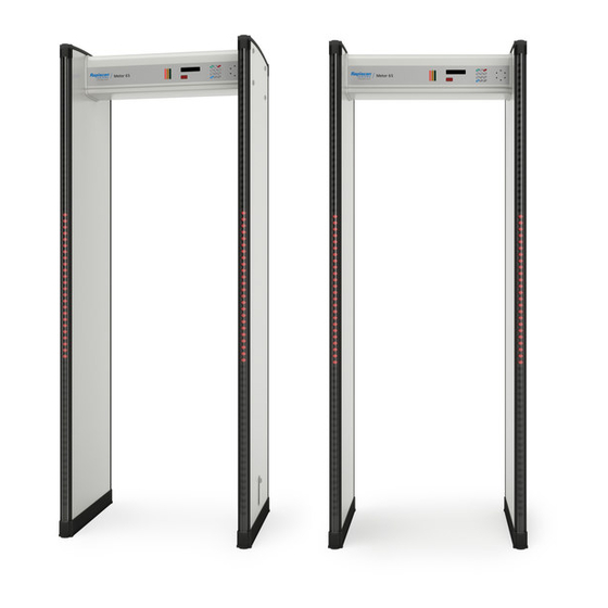
Metor 6M – металлодетектор универсальный проходной многозонный, предназначением которого есть поиск оружия. Данный прибор используют для досмотра посетителей в зданиях судов, тюрьмах, федеральных учреждениях, промышленных предприятиях, электростанциях, для досмотра пассажиров в морских портах и аэропортах, а также для досмотра посетителей в ресторанах, гостиницах, ночных клубах, казино, для контроля доступа на конференциях, на спортивных и других специальных мероприятиях, концертах, стадионах, в зданиях государственных органов и на мероприятиях по предотвращению ущерба на разных предприятиях.
Оcобенности:
- Независимые зоны
- Интеллектуальные счетчики проходов – надежные статистические данные
- Усовершенствованные функции – повышенная эксплуатационная пригодность
- Повышенный уровень безопасности
- Простота установки и эксплуатации
- Функция случайного сигнала тревоги
- Бренд:METOR
- Питание:90-264 В пер. тока/50-60 Гц. Аккумулятор: 12 В
- Чувствительность:100 уровней чувствительности для каждой программы
- Ширина прохода:760 х 2050 мм
- Уровень безопасности:IP 55 (EN 60529)
- Влажность:0-95%, без образования конденсата
- Температура эксплуатации:-20~+70
- Габариты:900 х 2240 х 700 мм
- Вес:58,8 кг
-
1. Металлодетектор Metor
2. Инструкция по эксплуатации
3. Упаковка
-
Page 1
Metor 6M Installation and Operating Manual 92102916 REV 5… -
Page 3: Table Of Contents
Metor 6M PAGE 1 Installation and Operating Manual 92102916 REV 5 Author Rev. T. Virtanen 92102916 Approved Date Document 27.1.2012 Product Archives Metor 6M CONTENTS PREFACE …………3 Definition of terms .
-
Page 4
Metor 6M PAGE 2 Installation and Operating Manual 92102916 REV 5 11. ACCESSIBILITY PARAMETERS ……..51 Access codes . -
Page 5: Preface
1. PREFACE 1. PREFACE Thank you for choosing a Metor product. These installation and operation instructions are intended for the installation and normal daily use of the equipment. In addition to these instructions, local laws and regulations, and requirements by authorities shall be observed.
-
Page 6: Definition Of Terms
Metor 6M PAGE 4 Installation and Operating Manual 1. PREFACE 92102916 REV 5 Definition of terms Some special terms used in this manual are explained below. WTMD — Walk Through Metal Detector Sensitivity — Parameter for defining the size of the metal items that will generate an alarm.
-
Page 7
Metor 6M PAGE 5 Installation and Operating Manual 92102916 REV 5 1. PREFACE Operating frequency — The frequency of the electromagnetic field generated by a WTMD. Usually WTMDs have several different operating frequencies. When calibrating a WTMD at the installation site the operating frequency with lowest interference level is chosen. -
Page 8: Important Instructions
The equipment shall always be connected to an earthed socket outlet. The equipment shall be disconnected from mains supply before servicing, cleaning, or moving it. Original Metor spare parts shall be exclusively used.
-
Page 9
Metor 6M PAGE 7 Installation and Operating Manual 92102916 REV 5 2. IMPORTANT INSTRUCTIONS Use a damp cloth for cleaning the equipment. Do not use any chemicals or liquid detergents. The end user is responsible for the final calibration of the equipment for the intended application. -
Page 10: Warranty
Metor 6M PAGE 8 Installation and Operating Manual 3. WARRANTY 92102916 REV 5 3. WARRANTY RAPISCAN SYSTEMS (RS) warrant their Products against defects in materials and workmanship in normal use for a period of two (2) years from the delivery to the customers, however, not more than twenty-six (26) months from the dispatch from the RS factory.
-
Page 11: Introduction
4. INTRODUCTION 4. INTRODUCTION Intended use The Metor 6M is a walk-through metal detector (WTMD) designed to detect metal objects people are carrying with them. The system is used primarily for weapons detection. Typical applications are: • Airports, seaports: passenger screening •…
-
Page 12: Main Components
Metor 6M PAGE 10 Installation and Operating Manual 4. INTRODUCTION 92102916 REV 5 Main components 1. Display and keypad 5. Receiver panel 2. Cross Piece 6. Transmitter panel 3. Traffic lights (option) 7. Remote control unit (option) 4. Electronics unit…
-
Page 13: Technical Data
Metor 6M PAGE 11 Installation and Operating Manual 92102916 REV 5 4. INTRODUCTION Technical data Power • Input, nominal ……..12.5 VDC, 2A • Input, absolute limits……12 — 15 VDC, 4A • Power consumption, typical….25 W (12 VDC) •…
-
Page 14
Metor 6M PAGE 12 Installation and Operating Manual 4. INTRODUCTION 92102916 REV 5 Dimensions and weight 90 / 95 76 / 81 Dimension….[cm] …..[in] Max. height ….224 ….88 Max. width (std)….. 90 ….35 Optional….95 ….37 Internal height …. -
Page 15: Installation Site
5. INSTALLATION SITE 5. INSTALLATION SITE When planning the installation site of the Metor 6M there are a few important things that should be considered. The optimum operation of the WTMD as well as maximum traffic flow at the security checkpoint can be ensured only when these factors have been taken into account.
-
Page 16
Metor 6M PAGE 14 Installation and Operating Manual 5. INSTALLATION SITE 92102916 REV 5 Radiated electrical interferences The distance between electrical interference sources and the receiver coil should be maximized. Recommended minimum distance is from 0.5 m to 4 m (20 in — 157 in). -
Page 17
Metor 6M PAGE 15 Installation and Operating Manual 92102916 REV 5 5. INSTALLATION SITE Recommended minimum distances from interference sources > 0.5 — 4 m / 20 — 157 in. > 0.5 — 2 m / 20 — 79 in. -
Page 18: Checkpoint Layout
Metor 6M PAGE 16 Installation and Operating Manual 5. INSTALLATION SITE 92102916 REV 5 Checkpoint layout The layout of a security checkpoint should be planned carefully before installing the equipment in order to maximize the traffic flow. In addition to the considerations regarding mechanical and electrical interferences (See “Installation…
-
Page 19: Side-By-Side Operation
The level of interference depends on the distance between the WTMDs, their operating frequency and sensitivity. Metor 6M has ten different operating frequencies. All the operating frequencies are suitable for side-by-side use.
-
Page 20
Metor 6M PAGE 18 Installation and Operating Manual 5. INSTALLATION SITE 92102916 REV 5 Frequency selection In side-by-side situation frequency auto search or manual frequency selection can be used (see example below). If frequency auto search function is used there might be temporary interferences among earlier WTMDs during the search. -
Page 21: Assembly
Metor 6M PAGE 19 Installation and Operating Manual 92102916 REV 5 6. ASSEMBLY 6. ASSEMBLY Mechanical assembly The items needed in installation are packed in the box containing the cross piece. For checking the distance of the coil panels there is a pasteboard gauge in the cross piece box.
-
Page 22
If necessary the zone display can be moved to the opposite side of the coil panel. 1. Lay the Metor 6M down. Place a support under the cross piece so that only the coil panel bottoms touch the ground (e.g. the cardboard package the cross piece came in) 2. -
Page 23
Metor 6M PAGE 21 Installation and Operating Manual 92102916 REV 5 6. ASSEMBLY 9. Lift the metal detector up to a vertical position in its final mounting location. Make sure that the coils are parallel, i.e. the distance at the top and at the bottom is NOTICE equal. -
Page 24: Electrical Connections
Metor 6M PAGE 22 Installation and Operating Manual 6. ASSEMBLY 92102916 REV 5 Electrical connections Connections 1. Tx panel connector 2. Rx panel connector 3. Zone display / Counter Tx connector (2 pcs) 4. Counter Rx connectors (2 pcs) 5. Serial port connections (4 pcs), all similar •…
-
Page 25: Installation Of The Power Supply Inside The Cross Piece
Metor 6M PAGE 23 Installation and Operating Manual 92102916 REV 5 6. ASSEMBLY Installation of the power supply inside the cross piece Should it be necessary to put the power supply inside the cross piece do as follows: • Using a draw thread pull an AC cable through the TX panel cable channel.
-
Page 26: Switching On
(see the next page). The standby function is used to set Metor 6M either on or standby mode. Operating standby mode requires that function is enabled from user interface and power is switched on from power switch.
-
Page 27: Display
Metor 6M PAGE 25 Installation and Operating Manual 92102916 REV 5 7. SWITCHING ON Display All functions of the WTMD are controlled with the display unit. The display unit consists of an alphanumeric display (1), status lights (2) and keypad (3).
-
Page 28: Keypad
See chapter 13. When enabled pressing for 2 seconds in normal operation will turn Metor 6M into standby mode. This button is used to set the volume (no access code required). This button can be pressed to receive instructions.
-
Page 29: Remote Control Unit (Option)
Installation and Operating Manual 92102916 REV 5 7. SWITCHING ON Remote control unit (option) All functions of the Metor 6M can be controlled with the optional remote control unit. The remote control unit operates within a distance of 3 m (120 in.) from the detector when the IR-beam is aimed at the display.
-
Page 30
Electronics Unit. After completing the above process the Metor 6M can be operated with the remote control unit. Up to ten remotes can be validated for Metor 6M following the same procedure with each one. -
Page 31: Super User Group Menu Structure
Metor 6M PAGE 29 Installation and Operating Manual 92102916 REV 5 7. SWITCHING ON Super User Group Menu Structure 1.1 SENSITIVITIES 1 METAL DETECTION 1.1.1 SENSITIVITY PARAMETERS 1.1.2 ZONE SENSITIVITITIES 1.1.2.1 ZONE 1 1.1.2.2 ZONE 2 1.1.3 AUTO SENSITIVITY 1.1.2.3 ZONE 3 1.1.4 AUTO FLOOR SENSITIVITY…
-
Page 32: Calibration
Metor 6M PAGE 30 Installation and Operating Manual 8. CALIBRATION 92102916 REV 5 8. CALIBRATION Calibration procedure 1. CHOOSE OPERATING FREQUENCY Choose a frequency which gives the least background interference level. It is recommended to use frequency auto search function. Also manual frequency search can be used.
-
Page 33: Before Commencing Calibration
Metor 6M PAGE 31 Installation and Operating Manual 92102916 REV 5 8. CALIBRATION The purpose of calibration is to set the WTMD’s operating characteristics to meet the required security level. The calibration is done before the introduction of the WTMD at the security check point. Before calibration the detection requirements have to be determined i.e.
-
Page 34: Choosing Operating Frequency
Metor 6M PAGE 32 Installation and Operating Manual 8. CALIBRATION 92102916 REV 5 Choosing operating frequency 1.1 SENSITIVITIES 1 METAL DETECTION 1.1.1 SENSITIVITY PARAMETERS 1.2 PROGRAM 1.1.2 ZONE SENSITIVITITIES 1.1.3 AUTO SENSITIVITY 1.1.4 AUTO FLOOR SENSITIVITY 1.3.1 SET FREQUENCY 1.3 FREQUENCY 1.3.2 SEARCH IN START-UP…
-
Page 35: Setting Speed Response
The object speed response of the Metor 6M can be affected by two parameters: High Speed and Low Speed. In practice, the effect of these parameters can be noticed only at the extreme limits of object speeds, i.e.
-
Page 36: Choosing Detection Program
1 METAL DETECTION PARAMETERS 1.2 PROGRAM Detection programs of the Metor 6M are divided into three groups: 1. Metor Security Programs. The group contains detection programs that are intended for general security use. The programs are designed to detect threat items made of various alloys (magnetic or non-magnetic) or a combination of alloys (magnetic and non-magnetic).
-
Page 37
Installation and Operating Manual 92102916 REV 5 8. CALIBRATION The relative sensitivity of the Metor 6M detection programs are given in the table next page. These programs have been compared to each other using factory set sensitivity and zone sensitivity values. -
Page 38
Metor 6M PAGE 36 Installation and Operating Manual 8. CALIBRATION 92102916 REV 5 PG01 PG02 PG03 PG04 PG10 PG11 PG12 PG13 PG14 PG20 PG21 PG22 PG23 PG24 AISI 316 Brass… -
Page 39
92102916 REV 5 8. CALIBRATION Metor 6M contains various detection programs. It is recommended that you compare different programs unless you select a program based on the requirements of a security organization that you are familiar with. When comparing different programs use various threatening and harmless objects relevant to your application. -
Page 40: Setting Detection Sensitivity
Metor 6M PAGE 38 Installation and Operating Manual 8. CALIBRATION 92102916 REV 5 Setting detection sensitivity The purpose of the detection sensitivity setting is to find the lowest sensitivity setting that still reliably detects the test objects using the detection program in question.
-
Page 41
Metor 6M PAGE 39 Installation and Operating Manual 92102916 REV 5 8. CALIBRATION Setting overall sensitivity 1.1 SENSITIVITIES 1 METAL DETECTION 1.1.1 SENSITIVITY PARAMETERS 1.2 PROGRAM 1.1.2 ZONE SENSITIVITITIES 1.1.3 AUTO SENSITIVITY 1.1.4 AUTO FLOOR SENSITIVITY Setting Overall Sensitivity Using Auto Sensitivity Function (recommended) 1. -
Page 42
Metor 6M PAGE 40 Installation and Operating Manual 8. CALIBRATION 92102916 REV 5 Setting floor level sensitivity The sensitivity of the equipment at floor level is checked and adjusted separately when the overall sensitivity of the gate has been adjusted. -
Page 43
Metor 6M PAGE 41 Installation and Operating Manual 92102916 REV 5 8. CALIBRATION Setting Floor Level Sensitivity using Auto Floor Sensitivity Function (recommended) 1.1 SENSITIVITIES 1 METAL DETECTION 1.1.1 SENSITIVITY PARAMETERS 1.2 PROGRAM 1.1.2 ZONE SENSITIVITITIES 1.1.3 AUTO SENSITIVITY 1.1.4 AUTO FLOOR SENSITIVITY 1. -
Page 44
Metor 6M PAGE 42 Installation and Operating Manual 8. CALIBRATION 92102916 REV 5 Manual setting of Floor Level Sensitivity Phase 1 Walk through the gate placing down the foot with the test piece at the middle of the gate. Seek the lower limit settings that detect the test object reliably. -
Page 45
3. The visual inspection • Mechanical condition, cables etc. The Metor 6M is ready for operation after the mechanical installation, connections and adjustments have been completed. The adjustments that effect the performance of the detector should be correctly made to optimize the operation for each… -
Page 46: Metal Detection Parameters
Metor 6M PAGE 44 Installation and Operating Manual 9. METAL DETECTION PARAMETERS 92102916 REV 5 9. METAL DETECTION PARAMETERS 1.1 SENSITIVITIES 1 METAL DETECTION 1.1.1 SENSITIVITY PARAMETERS 1.1.2.1 ZONE 1 1.1.2 ZONE SENSITIVITITIES 1.1.3 AUTO SENSITIVITY 1.1.2.2 ZONE 2 1.1.2.3 ZONE 3 1.2 PROGRAM…
-
Page 47
Metor 6M PAGE 45 Installation and Operating Manual 92102916 REV 5 9. METAL DETECTION PARAMETERS F1 — F10 Operating frequency setting to inhibit interference FREQUENCY between detectors operating near one another and to minimize the effect of interference from the environment. -
Page 48
Metor 6M PAGE 46 Installation and Operating Manual 9. METAL DETECTION PARAMETERS 92102916 REV 5 RESTORE Resets all the settings back to factory settings. FACTORY SETTINGS RND RATE 0 — 100 % Random alarm rate. The percentage of alarms caused (RANDOM by the non-alarming people. -
Page 49: Random Alarm
Metor 6M PAGE 47 Installation and Operating Manual 92102916 REV 5 9. METAL DETECTION PARAMETERS Random Alarm The random alarm operation is based on groups of 100 non-alarming people passing through the detector. The number of random alarms is a set percentage of every group of 100 non-alarming passes.
-
Page 50: Random Alarm For Alarming People
Metor 6M PAGE 48 Installation and Operating Manual 9. METAL DETECTION PARAMETERS 92102916 REV 5 Random Alarm for Alarming People The random alarm for alarming people (RDN/ALM) is based on groups of 100 alarming people passing through the detector. The number of random alarms is a set percentage of every group of 100 alarming passes.
-
Page 51: Audio/Visual Parameters
Metor 6M PAGE 49 Installation and Operating Manual 92102916 REV 5 10. AUDIO/VISUAL PARAMETERS 10. AUDIO/VISUAL PARAMETERS 2.1 VOLUME PARAMETERS 2.1.1 VOLUME 2 AUDIO/VISUAL PARAMETERS 2.1.2 VOLUME MIN 2.2 ALARM TONE 2.3 ALARM ON TIME 2.1.3 KEY VOLUME 2.4 ZONE DISPLAY PARAMETERS 2.4.1 ZONES…
-
Page 52: Zone Display
Metor 6M PAGE 50 Installation and Operating Manual 10. AUDIO/VISUAL PARAMETERS 92102916 REV 5 Zone display The zone display (1) uses a red light to indicate the approximate height of the object that has caused the alarm. The zone display consists of twenty…
-
Page 53: Accessibility Parameters
Metor 6M PAGE 51 Installation and Operating Manual 92102916 REV 5 11. ACCESSIBILITY PARAMETERS 11. ACCESSIBILITY PARAMETERS 3.1 USERS 3.1.1 ACCESS CODES 3.1.1.1 CHANGE OWN ACCESS CODE 3 ACCESSIBILITY PARAMETERS 3.1.1.2 CHANGE USER N ACCESS CODE 3.1.2 MANAGE USERS 3.1.2.1 ADD NEW USER 3.1.2.2 VIEW USERS…
-
Page 54: Access Codes
Metor 6M PAGE 52 Installation and Operating Manual 11. ACCESSIBILITY PARAMETERS 92102916 REV 5 COPY FROM Copies the current user IDs and group definitions into METOR => the remote control unit. The settings copied into the REMOTE remote control unit will remain there until new settings are copied in their place.
-
Page 55
Metor 6M PAGE 53 Installation and Operating Manual 92102916 REV 5 11. ACCESSIBILITY PARAMETERS Changing the access code of User 0 1. Press . When the program requests “ENTER USER ID:”, enter “0”. Press 2. Enter the User 0 access code, and press 3. -
Page 56: User Id Locking
Metor 6M PAGE 54 Installation and Operating Manual 11. ACCESSIBILITY PARAMETERS 92102916 REV 5 Resetting of access codes There may be situations when you need to reset User 0 access code. To do this press and hold the LEARN button (1) for more than 5 seconds.
-
Page 57: Creating New User Id
Metor 6M PAGE 55 Installation and Operating Manual 92102916 REV 5 11. ACCESSIBILITY PARAMETERS Creating new User ID 1. Press . When the program requests “ENTER USER ID:”, enter “0”. Press 2. Enter the access code, and press 3. Press to display “Accessibility parameters”.
-
Page 58: Disabling Keypad
Metor 6M PAGE 56 Installation and Operating Manual 11. ACCESSIBILITY PARAMETERS 92102916 REV 5 11. Select the desired accessibility setting for the menu item using key. Options are: <HIDDEN>, <READ-ONLY> or <FULL ACCESS>. 12. When the definitions are set, press .
-
Page 59: Statistics
RA: 14 RA = number of random alarms generated These counters are cleared with the 4.3 CLEAR STATISTICS command (numbers above are examples and might be different on an actual Metor 6M) ALM: ALM = number of natural alarms occurred…
-
Page 60: Traffic Counters
Metor 6M PAGE 58 Installation and Operating Manual 12. STATISTICS 92102916 REV 5 Traffic counters The equipment has a counter that registers the number of persons passed through and the number of alarms. The counters use IR transmitters and receivers (1) shown in the illustration in the Tx and Rx panel edge profiles.
-
Page 61: General Parameters
Metor 6M PAGE 59 Installation and Operating Manual 92102916 REV 5 13. GENERAL PARAMETERS 13. GENERAL PARAMETERS 5.1.1 METORNET 5.1 NETWORKING AND DATA 5.1.1.1 METORNET MODE 5 GENERAL PARAMETERS 5.1.1.2 METORNET PORT 5.2 POWER RELATED PARAMETERS 5.2.1 STANDBY MODE 5.2.2 POWER GUARD 5.3 I/O CONFIG…
-
Page 62: Standby Mode
• No alarms of people walking through the unit. Pressing again (2 seconds not needed) will resume normal operation. I/O Config The Metor 6M has two configurable digital I/O inputs and two configurable digital I/O outputs. Input configuration The inputs can be configured as: •…
-
Page 63
(double/reinforced insulation) must be used if circuit DANGER connected to line voltage must be controlled. Power Guard The Metor 6M is equipped with Power Guard function that alarms when the unit loses power (i.e. power cord is disconnected). -
Page 64: Diagnostics
Metor 6M PAGE 62 Installation and Operating Manual 14. DIAGNOSTICS 92102916 REV 5 14. DIAGNOSTICS 6.1.1 EM NOISE 6 DIAGNOSTICS 6.1 NOISE MEASUREMENTS 6.1.2 TOTAL NOISE 6.2 DIRECTIONAL DATA 6.2.1 P1 / P2 6.3 OPERATING TIME 6.2.2 A1 / A2 6.4 CELL1 / CELL2…
-
Page 65
Metor 6M PAGE 63 Installation and Operating Manual 92102916 REV 5 14. DIAGNOSTICS EM Noise EM Noise will measure only electromagnetic interferences from the environment. Start EM Noise measurement by pressing . The display unit will show used operation frequency in the left corner and text MEASURING in the middle of the display. -
Page 66: Accessories
15. ACCESSORIES 92102916 REV 5 15. ACCESSORIES The Metor 6M has the following optional accessories that are not included in the standard setup and can be ordered separately. Remote Control Set MRCS 5116 All functions of the Metor 6M can be controlled with the remote control unit.
-
Page 67: Networking
16. NETWORKING MetorNet 3 Pro Web The MetorNet 3 Pro Web is a browser- based Remote Security Management System for Metor walk-through metal detectors. MetorNet 3 Pro Web operates through Ethernet and can connect up to 255 Metors into one network.
-
Page 68: Maintenance
Metor 6M PAGE 66 Installation and Operating Manual 17. MAINTENANCE 92102916 REV 5 17. MAINTENANCE Error Messages ERROR MESSAGE INTERNAL ERROR CORRECTIVE ACTION Depends on error number; see next Cycle power on the unit, if reappears SYSTEM MESSAGE: table contact service…
-
Page 69
Metor 6M PAGE 67 Installation and Operating Manual 92102916 REV 5 17. MAINTENANCE RX Coil failure SYSTEM MESSAGE: Check RX coil resistances RX Cable failure RECEIVER FAILURE X! Replace MRXS Electrical failure (X is channel #) Check RX cable connector… -
Page 70: Other Error Situations
Metor 6M PAGE 68 Installation and Operating Manual 17. MAINTENANCE 92102916 REV 5 WARNING! POWER LOSS! Power cord disconnected or unit Press ‘C’ to clear warning or reconnect switched OFF (Power Guard was ON) power Zone display/counter cable not SYSTEM MESSAGE:…
-
Page 71
Metor 6M PAGE 69 Installation and Operating Manual 92102916 REV 5 17. MAINTENANCE The interference level too Used frequency not suitable for the Change operating frequency high operating environment (Additional reduction of interference level can be achieved by lowering the… -
Page 72: Service
The customer copy, with repair information, is returned with the repaired unit. • If the fault is repaired by the user or a Metor representative, the second and third copies should be sent to the factory.
-
Page 73: Information In Service Request
1. Identification of faulty product/part. The requested information is: • Metor model (for example Metor 6M) • Type of part (for example MELS 5144) or the name of the part • Serial number of the faulty part.
-
Page 74: Factory Repairs
Metor 6M PAGE 72 Installation and Operating Manual 18. SERVICE 92102916 REV 5 Factory repairs Principles of factory repair services: • Warranty requests cannot be handled without the above information. • Rapiscan Systems will charge the cost of testing and evaluation, if the part is not faulty.
-
Page 75: Ordering Spare Parts
Metor 6M PAGE 73 Installation and Operating Manual 92102916 REV 5 19. ORDERING SPARE PARTS 19. ORDERING SPARE PARTS How to order: 1. Identify the system where the spare part is needed • Type of the unit. • Serial number of the electronic unit (1), and software version.
-
Page 76: Disposal Of Equipment
Metor 6M PAGE 74 Installation and Operating Manual 20. DISPOSAL OF EQUIPMENT 92102916 REV 5 20. DISPOSAL OF EQUIPMENT When the equipment is taken out of use, it should be disposed of by observing the following environmental aspects: • The steel and aluminium of the metal detector gate structures, the copper of the cables, and the precious metals in the electronic circuits should be recycled as raw materials and used for production of new metal products.
-
Page 77: Contact Information
Metor 6M PAGE 75 Installation and Operating Manual 92102916 REV 5 21. CONTACT INFORMATION 21. CONTACT INFORMATION Use these addresses when ordering spare parts and in warranty or repair issues. United Kingdom’s Customer Service Center for Europe, Africa, Mid East Rapiscan Systems Ltd.
-
Page 78
Metor 6M Installation and Operating Manual 92102916 REV 5 ALPHABETICAL INDEX Frequency selection……….18 Access codes …………52 Accessibility parameters ……..51 General parameters……….59 Accessories…………64 Affect of Hi Speed and Lo Speed parameters on interference attenuation ……..34 Assembly………….. -
Page 79
Metor 6M Installation and Operating Manual 92102916 REV 5 Side-by-side operation……….. 17 Standby Mode…………60 Random Alarm for Alarming People……. 48 Statistics …………..57 Random Alarm …………47 Super User Group Menu Structure ……29 Ratings of recommended external power supply … 11 Switching on …………
Технические характеристики
Описание
Металлодетектор Metor 6M
Высокая надежность обнаружения устройства обеспечивается восьмью магнитными полями, которые взаимно пересекаются. Купить металлодетектор Metor 6M можно для применения в самых различных сферах (аэропортах, морских портах и вокзалах, государственных и федеральных учреждениях, атомных электростанциях, а также гостиницах, развлекательных учреждениях и мн.др.).
Особенности:
простая установка и эксплуатация;
эффективное шумоподавление посредством цифровой фильтрации;
оснащение различными программами позволяет купить детектор Metor 6M для эксплуатации в разных условиях;
каждая программа имеет 100 уровней чувствительности;
обнаружение по 8 зонам, настройки чувствительности каждой зоныосуществляется индивидуально;
постоянная активность детектирующего контура;
наличие счетчика числа проходов;
поддержка 5 частот для возможности одновременной работы нескольких устройств.
Комплектующие:
металлодетектор;
инструкция.
Просьба уточнять комплектацию и характеристики товара у менеджера перед покупкой.инструкция.
Таблица значений степеней защиты IP (пылевлагозащищенность)
Характеристики
| Характеристики металлодетекторов | |
| Влажность воздуха | 0-95%, без образования конденсата |
| Габариты | Внутренние: 760 (ширина) х 2050 (высота) мм. Внешние: 900 (ширина) х 2240 (высота) х 700 (глубина) мм |
| Гарантия | Два (2) года на запасные части и качество сборки |
| Источник питания | Сетевое напряжение: 90-264 В пер. тока/50-60 Гц. Аккумулятор: 12 В пост. тока. Потребление: 50 Вт (пер. ток), 40 Вт (пост. ток). Предохранитель: TIA 5×20 мм. Длина шнура питания: 2,5 м |
| Калибровка | Автоматическая или ручная |
| Масса брутто и объем с упаковкой | Общие: масса брутто: 75,5 кг, объем с упаковкой: 0,47 м3. Масса нетто: 58,8 кг. Катушки: масса брутто: 55,5 кг, объем с упаковкой: 0,35 м3. Поперечина + электроника: масса брутто: 20 кг, объем с упаковкой: 0,12 м3. |
| Подавление помех | Цифровое фильтрование процессором обработки сигнала. Несколько рабочих частот для подавления локальных электрических шумов |
| Подключение к сети | Совместим с дистанционной системой управления безопасностью MetorNet (Ethernet) |
| Рабочая температура | От -20 до 70 °C |
| Сигнал тревоги | Визуальный/звуковой сигнал. Буквенно-цифровой дисплей и зонный дисплей. Контактная группа реле удаленного сигнала тревоги (SPDT) |
| Уровень защиты | IP 55 |
| Чувствительность | 100 уровней чувствительности для каждой программы. Отдельные горизонтальные зоны; уровень чувствительности каждой зоны регулируется независимо в диапазоне 0-200% |
| Ширина прохода | 760 мм |
Сертификат и паспорт
Запросы на сертификат и/или паспорт, описание и/или дополнительную техническую и справочную информацию на Metor 6M просим направлять на электронную почту указанную на сайте.
Комплект поставки
- Арочный металлодетектор Metor 6M
- Паспорт изделия
- Сертификат на Metor 6M или отказное письмо
- Накладная на отгрузку
- Счет-фактура
Поставщик: ООО «ЦПИ»
Металлодетектор Rapiscan METOR-6M – это универсальный, проходной многозонный прибор, который используется в местах скопления людей. В основном он рассчитан на выявление оружия и достаточно быструю работу. Устройство идеально подойдет для установки в аэропортах, государственных учреждениях, а также в ночных клубах, гостиницах и подобных им заведениях.
Данная модель имеет небольшие размеры, легко монтируется в требуемом месте и может переустанавливаться при необходимости. Она оборудована звуковым сигналом тревоги, а также имеет световые и индикаторы. Детектор способен работать в температурном диапазоне от -20 до +70 °C.
| Артикул | 122293 |
| Гарантия | 24 месяца. |
| Страна производства | Китай |
| Инструкция | В комплекте. |
| Сертификат | Посмотреть |
Технические характеристики:
- Размеры (Ш,В,Г): 900/950 х 2240 х 700
- Проход (Ш,В): 760/810 х 2050
- Рабочая температура: От -20 до 60 °С
- Влажность воздуха: 0-95%, без образования конденсата.
- Класс защиты: IР 55 (EN 60529)
- Источник питания: Сетевое напряжение: 90-264 В пер. тока/50-60 Гц
- Аккумулятор: 12 В пост. тока (опция)
- Потребление: 50 Вт (пер. ток), 40 Вт (пост. ток)
- Длина шнура питания: 2,5 м
- Сигнал тревоги: Визуальный/звуковой сигнал. Буквенно-цифровой дисплей и зонный дисплей. Контактная группа реле удаленного сигнала тревоги (SPDT).
- Чувствительность: 100 уровней чувствительности для каждой программы. Отдельные горизонтальные зоны; уровень чувствительности каждой зоны регулируется независимо в диапазоне 0-200%.
- Калибровка: Автоматическая или ручная.
- Подавление помех: Цифровое фильтрование процессором обработки сигнала. Несколько рабочих частот для подавления локальных электрических шумов.
- Гарантия: Два года.
- Подключение к сети: Совместим с дистанционной системой управления безопасностью MetorNet.
Масса брутто и объем с упаковкой:
- Общие: масса брутто: 75,5 кг, объем с упаковкой: 0,47 м3.
- Масса нетто: 58,8 кг.
- Катушки: масса брутто: 55,5 кг,объем с упаковкой: 0,35 м3.
- Поперечина: масса брутто: 20 кг, объем с упаковкой: 0,12 м3.
* Информация о технических характеристиках, комплекте поставки, стране изготовления, внешнем виде и цвете товара в
интернет-магазине Борн носит справочный характер и основывается на последних доступных к моменту публикации сведениях.