- Возможность работы с прозрачными этикетками, этикетами любого цвета, с голографией т.д.;
- 3 режима обучения на работу с этикетками различной плотности;
- Время отклика менее 300 мкс;
- 2 дискретных выхода для контроля наличия этикетки / обрыв ленты;
- Габаритные размеры полностью соответствуют размерам оптических датчиков этикеток;
- Возможность настройки посредством LinkControl (требуется LCA-2 Koffer).
Контроль этикетки на производстве
Контроль этикетки на производстве фармакологических средств Применение датчика esf-1 позволяет успешно контролировать момент наклейки этикетки на каждое изделие благодаря очень малому времени отклика 300 мкс. При этом в случае обрыва ленты, датчик одновременно информирует об этом это путем срабатывания 2-го дискретного выхода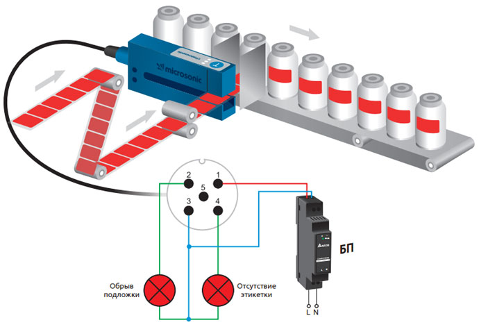
| Артикул | esf-1/CF | esf-1/CDF |
|---|---|---|
| Выходы | 1×Push-Pull (PNP/NPN) | 1×Push-Pull + 1 PNP |
| Характеристики выходов | Push-Pull, +UB -4 В, -UB +2 В, Imax = 100 мА, с защитой от КЗ, переключаемый НО/НЗ |
PNP, +UВ -3 В, Imax= 100 мА, защита от КЗ |
| Подключение | коннектор M8×1, 4-контакта | коннектор M12×1, 5-контактов |
| Управление | кнопка «Teach-in» | кнопка «Teach-in» + pin-5 |
| Время отклика | От 300 мкс до 2,25 мс, в зависимости от материала |
| Параметр | Значение |
|---|---|
| Частота ультразвука | 500 кГц |
| Рабочие поверхности | полотно от 20 до 400 г/м², ламинированная бумага и плёнки до 0,2 мм толщиной, самоклеющиеся плёнки, этикетки, наклейки с подложкой и т.д. |
| Напряжение питания, UB | = 20…30 В |
| Материал корпуса | анодированный алюминий пластик: PBT,PA |
| Материал сенсора | полиуретан эпоксидная смола с содержанием стекла |
| Степень защиты | IP65 |
| Индикаторы | 3 LED-индикатора (красный, жёлтый, зелёный) |
| Рабочая температура | +5…+60 °С |
| Температура хранения | -40…+85 °С |
При коммутации индуктивной нагрузки (катушек соленоидных
клапанов, э/м реле, контакторов) транзисторным выходом датчика,
рекомендуется обеспечить дополнительную защиту схемотехники
от возникающих импульсных перенапряжений.
Например, использовать устройство защиты от перенапряжений microsonic SF1 (поставляется отдельно).
| esf-1/C | / | ||
|---|---|---|---|
| Количество и тип выходов | |||
| 1 × Push-Pull (PNP/NPN) | F | ||
| 1 × Push-Pull + 1 PNP | DF | ||
| Интерфейс | |||
| IO-Link v 1.1 | A | ||
| Нет | — |
Пример: esf-1/CDF
Номер заказаesf-1/CDF/A
-

1 х Push-Pull + 1 х PNP
рабочий диапазонпленка с весом 20 г / м 2 до > 400 г / м 2, металлические ламинированные листы и пленки до 0,2 мм, самоклеящаяся пленка , наклейки на материал подложки
Модельgabelförmig
режим работыIO-Link
обнаружение метки/стыка
особенностиIO-Link
Smart Sensor Profile
средств измеренийимпульсном режиме с оценкой амплитуды
Преобразователь частоты500 kHz
рабочее напряжение UB20 — 30 VDC, защита от обратной полярности
пульсации напряжения± 10 %
ток холостого потребления≤ 50 mA
тип соединения5-контактным разъемом M12 инициатора
Выход 1релейный выход, метка/стык обнаружены
Push-Pull, UB-3 V, -UB+3 V,Imax = 100 mA
НЗК/НОК выбираемые, защита от короткого замыкания
Выход 2релейный выход
метка/стык обнаружены
web ошибка
PNP: I max = 200 mA (+U B -2 В)
НЗК/НОК выбираемые
защита от короткого замыкания
время реакцииот 300 мкс до 2,25 мс, в зависимости от материала
задержка до наличия< 300 ms
вход 1Вход COM порт синхронизационный вход teach-in вход
название продуктаesf-1/CDF/A
Код продукта16950
SIO поддержка режимада
COM режимеCOM2 (38,4 kBaud)
минута Время цикла4 ms
Формат данных процесса32 Bit PDI
Содержание данных процессаBit 0: initial state Pin 4; Bit 1: initial state Pin 2; Bit 2: web break; Bit 8-15: scale (Int. 8); Bit 16-31: measured value (Int. 16)
ISDU paramterIdentification, switched output, add-ons, temperature compensation, operation
Система командSP1 Teach-in, SP2 Teach-in, factory settings
SmartSensorProfilда
IODD версияIODD версии 1.1
Ширина вил6 mm
Вилка глубины70 mm
материаланодированный алюминий
ультразвукового преобразователяполиуретановой пены, эпоксидной смолы с содержанием стекла
Класс защиты по EN 60529IP 65
Рабочая температура+5°C до +60°C
температура хранения-40 ° C до +85 ° C
вес80 g
последующие версиибольшая ширина вилки / глубина
управления1 push-button
com input
возможности для настройкиРежим «обучения» через кнопки режим «обучения» через COM вход на контакт 5
LCA-2 c LinkControl
IO-Link
Synchronisationда
Индикаторы1x зелёный светодиод: рабочее состояние, 1x жёлтый светодиод: состояние выхода, второй контакт, 1x красный светодиод: состояние выхода, четвёртый контакт
особенностиIO-Link
Smart Sensor Profile

IO-Link Data Sheet
esf-1/CDF/A
esf-1/7/CDF/A
esf-1/15/CDF/A
microsonic GmbH / Phoenixseestraße 7 / 44263 Dortmund / Germany
T +49 231 975151-0 / F +49 231 975151-51 / E [email protected] / W microsonic.de
The content of this document is subject to technical changes. Specifications in this document are
presented in a descriptive way only. They do not warrant any product features.
MV-DO-198513-629461
1
IO-Link Data Sheet
Physical layer
esf-1/CDF/A
Ultrasonic label and splice sensor with pnp and PushPull switching output with IO-Link interface.
The fork depth is 55 mm.
esf-1/7/CDF/A
Ultrasonic label and splice sensor with pnp and PushPull switching output with IO-Link interface.
The fork depth is 70 mm.
esf-1/15/CDF/A
Ultrasonic label and splice sensor with pnp and PushPull switching output with IO-Link interface.
The fork depth is 150 mm.
Vendor Name
microsonic GmbH
Vendor ID
419 (0x01a3)
Device ID
72 (0x000048)
IO-Link Specification
1.1
Transmission Rate
COM 2 (38,400 Bd)
Process Data Length
32 Bit PDI
Minimum Cycle Time
4 ms
IO-Link Port Type
A (<200mA)
SIO Mode Supported
Yes
Smart Sensor Profile
Yes
Block Parameter
Yes
Data Storage
Yes
Product Name
Product ID
esf-1/CDF/A
16950
esf-1/7/CDF/A
16953
esf-1/15/CDF/A
16952
Pin assignment
IO-Link mode
The sensors esf-1/CDF/A, esf-1/7/CDF/A and esf-1/15/CDF/A are
IO-Link capable in accordance with IO-Link specification 1.1. Each
sensor has an IO-Link communication interface on pin 4.
Direct access to process and diagnosis data is possible via the IOLink interface. The parameterization of the sensors is possible during operation.
IODD description file
The sensors have a common device description file. The IODD contains:
› Communication features
› Device parameter with allowed values
and default value
› Identification-, processing and
diagnostic data
› Device data
› Text description
› Picture of the device
› Logo of the manufacturer
2
Label and splice sensor
A label sensor has the task to detect labels glued to a backing material. For this purpose, the label sensor evaluates the signal level
difference between the backing material and the backing material
with labels.
then stored in the parameter material adjustment. The thresholds
to detect labels and splices are then calculated and stored in SP1
and SP2. The parameters are newly determined with each Teach-in
process.
A splice sensor has the task to detect a splice in a web material.
The end and beginning of the web material can be joined together
as a splice and glued with an adhesive tape, or can be glued overlappingly. For this purpose, the splice sensor evaluates the signal
level difference between the web material and the splice.
The Teach-in procedure can be carried out manually with the button on the label and splice sensor or with pin 5 via the controls.
The signal differences between backing material and backing material with labels or web material and splice can be very slight. To
ensure a reliable distinction, the label as well as the splice sensor
has to learn each respective material: During the Teach-in process,
the ultrasonic transmitter output and ampflification factor of the
internal analog amplifier will be adjusted to the backing material
of the labels or the web material. The determined parameters are
Many parameters of the sensor are accessible via IO-Link. The parameter can be read or even partly written. The parameters can
be read out to set up a recipe management. Optionally, Teach-in
procedures via button or pin 5 can be started with IO-Link.
The label and splice sensor has to be calibrated to every material via the Teach-in procedures. For data storage or recipe management, the material-specific parameters can be read out and
written back. It is not recommendable to change the determined
parameters via IO-Link afterwards.
3
Process data
The process data are cyclically transmitted data. The length of the
process data of esf-1 sensors are 4 byte.
Byte 1
31
30
29
28
27
Byte 2
26
25
24
23
22
21
Byte 3
15
14
13
12
11
20
19
18
17
16
2
1
0
Byte 4
10
9
8
7
6
Description
Value range
5
4
3
0
=
1 Initial state (SSC1)
0 = False
1 = True
1
=
2 Initial state (SSC2)
0 = False
1 = True
2
=
Web break
0 = False
1 = True
8
15
=
Process data scale
-1
Process data
0...1,023 = Measured value
32,764 = No measurement data
-32,760 = Outside the detection range (-)
32,760 = Outside the detection range (+)
16
31
=
Scale
is the scaling of the process data. The measured value of the
sensor is calculated as stated
Process data x 10(Scale) = measured value
For example: 642 x 10 -1 = 64,2
Measurement data channel description
Index
Subindex
Term
Data type
16512
0
Measurement data channel description
Record
Access
Default value
1
Lower limit
UInt32
RO
0
2
3
Upper limit
UInt32
RO
1,023
Unit code
UInt16
RO
0
4
Scale
Int8
RO
-1
Lower limit
The lower limit is the smallest measured value that the sensor can
output.
Upper limit
The upper limit is the biggest measured value that the sensor can
output.
Unit code
The measuring value is dimensionsless.
Scale
is the scaling of the process data. The measured value of the
sensor is calculated as stated:
Process data x 10(Scale) = measured value
For example: 642 x 10 -1 = 64,2
4
Teach-in
Index Subindex
Term
Data type Access
2
System Commando
UInt8
WO
58
Teach-in channel
UInt8
RW
0
0 = SSC1: Default: pin 4 (push-pull)
1 = SSC1: Pin 4 (push-pull)
59
Teach-in status
UInt8
RO
0
Bit 0...3:
0 = Idle
1 = SP1 success
2 = SP2 success
3 = SP12 success
4 = Wait for command
5 = Busy
7 = Error
0
Teach-in configuration
Record
1
Splice threshold
UINT8
RW
20
5...50 %; resolution in %
2
Teach-in type
UINT8
RW
0
0 = Label dynamic
1 = Label static
2 = Splice
Material adjustment
UINT32
RW
400
500
Event number
dec
hex
36003
0x8ca3
Default value Value range
75 = Teach-in start
76 = Teach-in next step / end
79 = Teach-in abort
Event type
Event description
Warning
Material adjustment data record does not match the sensor.
System Commando
The system command is used to execute application commands,
Teach-in commands and IO-Link specific commands.
and stored in SSC1 and in material adjustment.
In addition, the threshold values are determined and stored in
SSC2 for optional splice evaluation.
Teach-in channel
The target channel of the Teach-in can be selected via this index.
SSC1 can be parametericed.
1 = Label static
With this static Teach-in for labels, the sensor first learns the backing material, then the backing material with label. The calculated
parameters are stored in SSC1.
In addition, the threshold values are determind and stored in SSC2
for optional splice evaluation.
Teach-in status
The Teach-in status indicates the state of the current adjustment.
Splice threshold
The threshold value for the splice is the percentage reduction on
SP1, see description Switched Signal Channel (SSC), and the percentage surcharge on SP2, see description SSC. To detect a splice,
the measuring value has to be below or above the value of the
splice threshold. After changing the splice threshold, the Teach-in
procedure for the splice sensor has to be started again.
Teach-in type
0 = Label dynamic
The backing material with labels must be guided through the fork
at a constant speed. With this Teach-in type, the parameters for
backing material and backing material with labels are determined
esf-1 as label sensor
5
Teach-in
2 = Splice
The web material is guided through the fork at a constant speed.
The parameters for the backing material are determined and stored in the parameter material adjustment as well as in SSC1 and
SSC2.
Material adjustment
The parameter material adjustment is the hardware-specific adjustment from a previous Teach-in procedure. The material adjustment is sensor-specific and should not be transmitted from one
sensor to another.
The parameter material adjustment can be used together with the
settings of SSC1, SP1 and SP2 as well as SSC2, SP1 and SP2 to
create a material management for this sensor. If the material adjustment does not match the sensor or was not generated by the
sensor, a warning event (36003) is set by the sensor. This event will
not be cancelled until the parameter material adjustment matches
the sensor again.
esf-1 as splice sensor
Teach-in - procedure for Teach-in initiated by the master
Teach-in type label dynamic
Initialization
1. In parameter <Teach-in type> (index 400.2) write the value 0 for "Label dynamic".
2. Insert backing material with labels into the fork.
Teach-in process
1. Move the backing material with labels through the fork at approx. 100 ... 200 mm/sec.
2. Write the value 75 for "Teach-in start" in parameter <system command> (index 2).
Read out the parameter <Teach-in status> (index 59).
3.1 If the parameter <Teach-in status> (index 59) contains the value 5, repeat step 3 after a waiting time of e.g. 500 ms.
3.2 If the parameter <Teach-in status> (index 59) contains the value 1, 2 or 3, the process is successfully completed.
End
3.3 If the parameter <Teach-in status> (index 59) contains the value 7, the Teach-in procedure was not successful.
Abort
3.4 If the parameter <Teach-in status> (index 59) still contains the value 5 after a time to be defined (e.g. 10 seconds),
continue with step 4.
4. Write the value 79 for "Teach-in abort" in parameter <system command> (index 2).
The sensor aborts the adjustment.
Abort
6
Teach-in - procedure for Teach-in initiated by the master
Teach-in type label static
Initialization
1. In parameter <Teach-in type> (index 400.2) write the value 1 for "static label".
2. Place 5 to 30 cm of backing material without labels in the fork.
Teach-in procedure
1. Write the value 75 for "Teach-in start" in parameter <system command> (index 2).
2. Move the backing material in the fork slowly back and forth over the length at least 3 times, this process must take at least 3 seconds.
3. Write the value 76 for "Teach-in next step / end" in parameter <system command> (index 2).
4. Place the backing material with labels in the fork. Make sure that the fork now measures a label in the middle.
5. Write the value 76 for "Teach-in next step / end" in parameter <system command> (index 2).
6. Move the label in the fork slowly back and forth over the label length at least 3 times. Make sure that only the label and not the
edge of the label is measured.
7. Write the value 76 for "Teach-in next step / end" in parameter <system command> (index 2).
8. Read the parameter <Teach-in status> (index 59).
8.1 If the parameter <Teach-in status> (index 59) contains the value 1, 2 or 3, the Teach-in process is successfully completed.
End
8.2 If the parameter <Teach-in status> (index 59) contains the value 7, the Teach-in process was not successful.
Abort
Teach-in type splice
Initialization
1. In parameter <Teach-in type> (index 400.2) write the value 2 for "splice".
2. Select the value for the splice threshold in parameter <splice threshold> (index 400.1). The recommended default value is 20%.
3. Insert web material without splice into the sensor.
Teach-in procedure
1. Write the value 75 for "Teach-in start" in parameter <system command> (index 2).
2. Move the web material slowly through the fork, depending on the material, 20 cm (plastic foils) to 2 m (recycled paper).
The process must take at least 3 seconds.
3. Write the value 76 for "Teach-in next step / end" in parameter <system command> (index 2).
4. Read out the parameter <Teach-in status> (Index 59).
4.1 If the parameter <Teach-in status> (Index 59) contains the value 1, 2 or 3, the Teach-in process is successfully completed.
End
4.2 If the parameter <Teach-in status> (Index 59) contains the value 7, the Teach-in process was not successful.
Abort
7
SSC - Switched Signal Channel
SSC1 - Switched Signal Channel 1 - Pin 4
Index Subindex
Term
Data type Access
60
0
SSC1 parameter
Record
1
SP1, setpoint 1
Int16
2
SP1, setpoint 2
Int16
0
SSC1 configuration
Record
1
Logic
2
61
100
Default value
Value range
RW
300
0..1,023; resolution in 0,1
RW
508
0..1,023; resolution in 0,1
UInt8
RW
0
0 = High active
1 = Low active
Mode
UInt8
RW
1
0 = Output deactivated
1 = Only lower threshold (SP1) (label/splice)
2 = Both thresholds (SP1 and SP2) (splice)
130 = Only upper threshold (SP2) (splice)
0
SSC1 advanced
configuration
Record
2
Switch-off delay
UInt8
RW
0
0…255; resolution in measuring repetition rates
Default value
Value range
SSC2 - Switched Signal Channel 2 - Pin 2
Index Subindex
Term
Data type Access
62
0
SSC2 parameter
32-bit
Record
1
SP1, setpoint 1
Int16
RW
300
0..1,023; resolution in 0,1
2
SP2, setpoint 2
Int16
RW
508
0..1,023; resolution in 0,1
0
SSC2 Configuration
32-bit
Record
1
Logic
UInt8
RW
0
0 = High active
1 = Low active
2
Mode
UInt8
RW
132
0 = Output deactivated
1 = Only lower threshold (SP1) (label/splice)
2 = Both thresholds (SP1 and SP2) (splice)
130 = Only upper threshold (SP2) (splice)
132 = Web break
134 = Missing label
135 = Mismatched label length
0
SSC2 advanced
configuration
Record
2
Switch-off delay
UInt8
63
100
RW
0…255; resolution in measuring repetition rates
8
SSC - Switched Signal Channel
SP1, Setpoint 1 and SP2, Setpoint 2
SP1 and SP2 are the threshold levels to detect label and splice.
These threshold values are determined by a Teach-in procedure.
Mode
is selected by the Teach-in type and can optionally be changed
later. The special functions "Web break", "Missing label" and
"Mismatched label length" are available for SSC2, which can
only selected via IO-Link.
0 = Output deactivated
The switching output is deactivated and is not set.
1 = Only lower threshold (SP1) (label/splice)
If the measured value of the sensor is below the value of SP1, the
output is set. SP2 is not used in this evaluation.
This is the default setting for scanning labels.
2 = Both thresholds (SP1 and SP2) (splice),
If the measured value of the sensor is below the value of SP1 and
above the value of SP2, the output is set.
This is the default setting for detecting a splice.
130 = Only upper threshold (SP2) (splice)
If the measured value of the sensor is above the value of SP2, the
output is set.
132 = Web break
The output is set as soon as the sensor detects a web break.
134 = Missing label
The output is set if the sensor detects a missing label. The prerequisite for this is a constant material flow at a constant speed.
135 = Mismatched label length
The output is set if the sensor detects a faulty label (± 50% of the
usual length). The prerequisite for this is a constant material flow
at a constant speed.
Logic
0 = High active
The output is set = +UB
1 = Low active
The output is set = -UB
Switch-off delay
The switch-off delay specified as the number of measurement
repetition rate extends the status output set. The measurement
repetition rate is dependent on scanned material. With the same
switch-off delay, but with different materials, the real switch-off
delay varies in ms.
9
User interface
Index Subindex
Term
Data
type
370
0
Button and pin 5
Record
1
Teach-in input
2
371
372
Access
Default value
Value range
UInt8
RW
1
0 = Inactive
1 = Button and pin 5 active
2 = Only pin 5 active
3 = Only button active
Manual Teach-in mode
UInt8
RW
0
0 = Standard Teach-in methods
1 = QuickTeach label sensor
2 = QuickTeach splice sensor
0
LED
Record
1
Mode
UInt8
RW
1
0 = off
1 = on
4 = Find me!
0
Teach-in feedback
Record
1
Mode
UInt8
RW
0
0 = Inactive
1 = Feedback on pin 2 and pin 4
2 = Feedback on pin 2
3 = Feedback on pin 4
Event code
Type
Description
dezimal
hex
36000
0x8CA0 Notification
Teach-in is not successful.
36001
0x8CA1 Notification
Teach-in is successful.
36004
0x8CA4 Warning
Manual Teach-in is executed.
The sensor has three LEDs, a button and a control input via pin 5.
Teach-in input
0 = Inactive
1 = Button and pin 5 active
2 = Only pin 5 active
3 = Only button active
The LEDs can be switched off in normal operation and only
temporarily activated for a teach-in. In Find me! operation, all
LEDs of the sensor flash simultaneously. This helps to locate the
sensor in a machine.
The Teach-in input parameter can be used to switch off specific
input options.
Teach-in feedback mode
0 = Inactive
1 = Feedback on pin 2 and pin 4
2 = Feedback on pin 2
3 = Feedback on pin 4
Manual Teach-in mode
0 = Standard Teach-in methods
1 = QuickTeach label sensor
2 = QuickTeach splice sensor
The Teach-in feedback is intended for the QuickTeach in SIO mode:
If the controller initiates a QuickTeach in SIO mode via pin 5 (or if
the button is pressed), the controller can query at pin 2 and/or pin
4 whether this teach-in was successful.
The selection of the Teach-in mode facilitates the manual Teach-in
of the sensor. If the sensor is only used for one operating mode
- label or splice - you can use QuickTeach to set a simplified Teachin, which you must activate and define once. The QuickTeach label
sensor corresponds to the Teach-in type Label dynamic (Index
400.2 = 0). The QuickTeach splice sensor corresponds to the
Teach-in type splice (Index 400.2 = 2).
This function is activated with the parameter Teach-in feedback
mode (Index 372.1).
If QuickTeach is successfully performed via pin 5 (or the key),
output pin 2, pin 4 or both will be set for 300 ms 200 ms after the
end of this process.
LED mode
0 = off
1 = on
4 = Find me!
10
User interface
QuickTeach
1
Pin 5 or button
A)
0
1
Pin 2 / Pin 4
0
QuickTeach
successful
B)
Normal operation
200 ms
{
300 ms
Query window
for the control
A) With QuickTeach labels, the controls can reset pin 5 at an early
stage as soon as there is a change of flankes "QuickTeach successful" has been detected. Or the controls ask 200 ms after pin 5 has
been reset in the 300 ms wide query window whether QuickTeach
was successful.
B) With QuickTeach splice, the change of flankes "QuickTeach successful" only occurs 200 ms later after the controls have reset pin 5.
In the 300 ms wide query window, the controls can query whether
QuickTeach was successful.
11
Synchronization
Index Subindex
Term
Data type Access
350
0
Synchronization
Record
1
Mode
UInt8
RW
Default value
Value range
0
0 = off
1 = on
control inputs must be connected to each other and mode 1 (=
on) must be selected.
If several esf-1 sensors are operated in a confined space, they
can influence each other. To avoid this, the esf-1 sensors can be
synchronized with each other. For this purpose, all Teach-in/Com
Temperature compensation
Index Subindex
Term
Data type Access
300
0
Temperatur compensation
Record
1
Mode
UInt8
RW
Default value
Value range
0
0 = off
1 = on
compensation. Only when the ambient temperature fluctuates by
more than 20 °C in a short time should temperature compensation
be switched on as an option.
The sensor is equipped with an internal temperature sensor, which
can compensate the temperature dependence of the amplitude
loss in the air. Normally it is not necessary to activate temperature
Sensor diagnosis
Index Subindex
Term
Data type Access
2000
0
Temperature
Record
1
Sensor temperature
Int16
RO
Default value
Value range
200
-560...1,560; resolution in 0,1 °C
Default value
Value range
The sensor displays the current sensor temperature.
Measurement diagnosis
Index Subindex
Term
Date type Access
2001
0
Measurement
Record
1
Measurement repetition
rate in SIO mode
UInt16
RO
30
30...195
resolution in 0,1 ms
2
Measurement repetition
rate in IO-Link mode
UInt16
RO
400
400...13,000
resolution in 0,1 ms
3
Quality of the last
Teach-in
UInt8
RO
Measurement repetition rate in SIO mode
The value indicates the repetition rate of the sensor when it is
operated with the current material adjustment in SIO mode.
Measurement repetition rate in IO-Link mode
The value specifies the repetition rate under IO-Link. This
depends on the master, which determines the time.
0...255:
0 = low quality
255 = high quality
Quality of the last Teach-in
The quality of the Teach-in is a value to provide a direct
comparison between several identical adjustment processes with
the same material. The larger it is, the better the adjustment.
12
Identification
Index
Term
Data type
Access
Default value
13
ProfileCharacteristic
Array UINT16
RO
14
PDInputDescriptor
Array OctetString3
RO
16
VendorName
String
RO
microsonic GmbH
17
VendorText
String
RO
Unser Herz schallt ultra.
18
ProductName
String
RO
19
ProductID
String
RO
20
ProductText
String
RO
21
SerialNumber
String
RO
23
FirmwareRevision
String
RO
24
ApplicationSpecificTag
String
RW
ProfileCharacteristic
The ProfileCharacteristic is an array of all profiles and function
classes supported by the sensor.
PDInputDescriptor
The PDInputDescriptor displays the breakdown of all data present
in the PDI in an array.
VendorName
The VendorName contains the name of the manufacturer.
VendorText
The VendorText contains the claim of the manufacturer.
ProductName
The ProductName contains the designation of the sensor used.
Ultrasonic sensor
***
ProductID
The ProductID contains the part number of the sensor used.
ProductText
The ProductText describes the sensor used.
SerialNumber
The SerialNumber is defined by the manufacturer.
FirmwareRevision
The FirmwareRevision shows the firmware version of the application used by the manufacturer.
ApplicationSpecificTag
The ApplicationSpecificTag can be used to store information
about the location or use of this sensor in the sensor setting.
System Command
Index Subindex
Term
Data type Access
2
System Command
UInt8
RW
Default value
Value range
130 = Restore factory settings
Back to factory setting
If the value 130 is written into index 2, all parameters of the
sensor are reset to factory setting.
13
Parameter access
The sensor is cyclically requested by the master to communicate.
With each communication the measured value is sent from the
sensor to the master. Part of this communication is the Indexed
Service Data Unit channel (ISDU channel). This channel is used to
write or read data acyclically to the sensor. This means that writing
or reading a parameter can take several communication cycles.
Error Code
Each communication of the master via the ISDU channel is
answered by the sensor. The sensor only processes aparameter
after it has been fully transmitted. Parameters, diagnostic data,
events and system commands are sent via this ISDU channel.
If the sensor discovers errors during parameter accessing, it reports
these with corresponding error codes.
Description
dezimal
hex
0
0x0000
No error
32768
0x8000
Device application error – no details
32785
0x8011
Index not available
32786
0x8012
Subindex not available
32800
0x8020
Service temporarily not available
32801
0x8021
Service temporarily not available – local control
32802
0x8022
Service temporarily not available
32803
0x8023
Access denied
32816
0x8030
Parameter value out of range
32817
0x8031
Parameter value above limit
32818
0x8032
Parameter value below limit
32819
0x8033
Parameter length overrun
32820
0x8034
Parameter length underrun
32821
0x8035
Function not available
32822
0x8036
Function temporarily unavailable
32832
0x8040
Invalid parameter set
32833
0x8041
Inconsistent parameter set
32898
0x8082
Application not ready
Device Access Locks
Index Subindex
Term
Data type Access
Default value
12
Device Access Locks
UInt16
RW
0
Bit 0: Parameter (write) Access Lock
RW
0
0 = off
1 = on
Bit 2: Local Parameterization Lock
RW
0
0 = off
1 = on
Bit 3: Local User Interface Lock
RW
0
0 = off
1 = on
The Device Access Locks are a specified IO-Link function. The
parameter DeviceAccessLocks enables the control of the device
behavior. Device functions can be deactivated via defined bits in
this parameter.
Parameter (write) Access Lock
If this bit is set, write access to application parameters and some
IO-Link specific parameters is disabled.
Value range
Local Parameterization Lock
If this bit is set, the parameterization is disabled via local
operating elements such as button / pin 5 on the device.
Local User Interface Lock
If this bit is set, use of the user interface on the device is disabled
and the display is switched off.
14
Events
Code
Type
Description
dezimal
hex
16384
0x4000
Error
Temperature fault
16912
0x4210
Warning
Device temperature over-run
16928
0x4220
Warning
Device temperature under-run
36000
0x8ca0
Notification
Manual Teach-in is not successful.
36001
0x8ca1
Notification
Manual Teach-in is successful.
36003
0x8ca3
Warning
Material adjustment data record does not match the sensor.
36004
0x8ca4
Warning
Manual Teach-in is executed.
Events are sent from the sensor to the master. This is done asynchronously via the ISDU channel of IO-Link. The master acknowledges these events in the sensor and stores them in the master
memory. There a PLC can read out the events. Several events can
be present simultaneously in the sensor.
Events are divided into three types.
•
"Notifications" are for general information or non-critical
states of the sensor and are sent each time the sensor state
occurs again.
•
"Warnings" indicate a possible functional limitation of the
sensor. These events are present until the reason for the function restriction is eliminated or switched off.
•
"Error" events indicate a sensor that is not functional. These
events are present until the reason for the function restriction
is removed or switched off.
Manual Teach-in is successful
A Teach-in via button or pin 5 was executed and successfully completed. The parameters have changed.
Material adjustment data record does not match the sensor
The transfered parameter material adjustment does not match
with this sensor. The function of the sensor cannot be guaranteed.
Manual Teach-in is executed
At the sensor, a Teach-in is carried out via button or pin 5. (During
a Teach-in process, the status of the outputs are frozen.)
Temperature fault
The operating temperature of the sensor has been significantly
exceeded, the function cannot be guaranteed. The sensor may be
damaged.
Device temperature over-run
The operating temperature of the sensor has be exceeded. A correct functioning of the sensor cannot be ensured.
Device temperature under-run
The operating temperature of the sensor has fallen below the minimum. A correct functioning of the sensor cannot to ensured.
Manual Teach-in is not successful
A Teach-in via button or pin 5 was executed and terminated incorrectly. The parameters have not changed.
15
Device status
Index Subindex
Term
Data type
Access
Default value
Value range
32
Int16
Error count
RO
0
0...65,535
36
UInt8
Device status
RO
0
0 = Device is OK.
1 = Maintance required
2 = Out of specification
3 = Functional check
4 = Failure
37
Array
Detailed device
status
RO
0
Error count
As soon as an event of the type error is detected in the sensor,
the error counter is incremented. The counter is set to 0 each
time operating voltage is switched on.
Device status
If no events can be read out or the sensor is switched from SIO
mode to IO-Link mode and the sensor is still to be monitored, it
is recommended to read this variable cyclically. The device status
shows the entire status of the sensor depending on the problem
that has occurred.
Detailed device status
In the detailed device status, all active error and warning events
are listed until they are reset by the sensor as soon as the root
cause has been eliminated.
Data storage
The sensors support data storage according to IO-Link version 1.1.
Data storage enables the master to store the entire parameter
set of the sensor. If the sensor has to be replaced, the data set is
loaded from the master into the replacement device.
The parameter material adjustment and SP1 as well as SP2 are
hardware dependent. After exchanging a sensor it is recommended
to carry out the material adjustment again.
The data storage is completely controlled by the master and is a
function of IO-Link to be configured in the master. Nothing has to
be configured in the sensor.
Block parameterization
Index
2
Subindex
Term
Data type
Access
System Commando
UInt8
WO
The block parameterization is a specified IO-Link function. The use
of this function is recommended if several parameters have to be
changed simultneously.
Each individual parameter write access is immediately implemented
in the sensor. This also includes a consistency check against other
parameters and immediate transfer to the application if the inspection is successful. If parameters are transferred in an unfavourable
sequence, the consistency check may fail.
Default value
Value range
1 = ParamUploadStart
2 = ParamUploadEnd
3 = ParamDownloadStart
4 = ParamDownloadEnd
5 = ParamDownloadStore
6 = ParamBreak
In block parameterization, on the other hand, all parameters are
first written and then the consistency check is performed for all
transferred parameters. The parameters are only stored in the sensor if this consistency check was successful.
This block parameterization also applies analogously to reading out
parameters.
16
Appendix: IO-Link data overview
Index Subindex
Term
Data Type
Access
2
System Commando
UInt8
WO
Device Access Locks
UINT16
12
13
Default Value
1 = ParamUploadStart
2 = ParamUploadEnd
3 = ParamDownloadStart
4 = ParamDownloadEnd
5 = ParamDownloadStore
6 = ParamBreak
75 = Teach-in start
76 = Teach-in next step /
end
79 = Teach-in abort
130 = Restore factory
settings
RW
0
Bit 0: Parameter (write)
Access Lock
RW
0
0 = off
1 = on
Bit 2: Local Parameterization Lock
RW
0
0 = off
1 = on
Bit 3: Local User Interface Lock
RW
0
0 = off
1 = on
ProfileCharacteristic
Array
UINT16
PDInputDescriptor
Array OctetString3
16
VendorName
String
microsonic GmbH
17
VendorText
String
Unser Herz schallt ultra.
18
ProductName
String
19
ProductID
String
20
ProductText
String
21
SerialNumber
String
23
FirmwareRevision
String
24
ApplicationSpecificTag
String
32
Error count
Int16
RO
0
36
Device status
UInt8
RO
0
37
Detailed device status
Array
RO
0
Process data input
OctetString4
RO
Teach-in channel
UInt8
RW
0
Teach-in status
UInt8
R/O
0
14
40
58
59
Value Range
Ultrasonic sensor
***
0 = Device is OK.
1 = Maintance required
2 = Out of specification
3 = Functional check
4 = Failure
0 = SSC1: Default: Pin 4 (push-pull)
1 = SSC1: Pin 4 (push-pull)
Bit 0..3:
0 = Idle
1 = SP1 success
2 = SP2 success
3 = SP12 success
4 = Wait for command
5 = Busy
7 = Error
17
Appendix: IO-Link data overview
Index Subindex
Term
Data Type
60
0
SSC1 parameter
Record
1
SP1, Setpoint 1
61
62
63
100
101
300
350
Access
Default Value Value Range
Int16
RW
300
0..1,023; resolution in 0,1
Int16
RW
392
0..1,023; resolution in 0,1
0
0 = High active
1 = Low active
2
SP1, Setpoint 1
0
SCC1 configuration
1
Logic
UInt8
RW
2
Mode
UInt8
RW
0
SSC2 parameter
Record
1
SP1, Setpoint 1
Int16
RW
300
0..1,023; resolution in 0,1
2
SP2, Setpoint 2
Int16
RW
392
0..1,023; resolution in 0,1
0
SSC2 configuration
Record
1
Mode
UInt8
RW
132
0 = Output deactivated
1 = Only low threshold (SP1) (label/splice)
2 = Both thresholds (SP1 and SP2) (splice)
130 = Only high threshold (SP2) (splice)
132 = Web break
134 = Missing label
135 = Mismatched label length
2
Logic
UInt8
RW
0
0 = High active
1 = Low active
0
SSC1 advanced
configuration
Record
1
Switch-On delay
UInt8
RW
0
0…255;
resolution in measurement cycle
2
Switch-Off delay
UInt8
RW
0
0…255;
resolution in measurement cycle
0
SSC2 advanced
configuration
Record
1
Switch-On delay
UInt8
RW
0
0…255;
resolution in measurement cycle
2
Switch-Off delay
UInt8
RW
0
0…255;
resolution in measurement cycle
0
Temperature
compensation
Record
1
Mode
UInt8
RW
0
0 = off
1 = on
0
Synchronization
Record
1
Mode
UInt8
RW
0
0 = off
1 = on
0 = Output deactivated
1 = Only low threshold (SP1) (label/splice)
2 = Both thresholds (SP1 and SP2) (splice)
130 = Only high threshold (SP2) (splice)
18
Appendix: IO-Link data overview
Index
Subindex
Term
Data Type
370
0
Button and pin 5
Record
1
Teach-in input
2
371
372
400
Access
Default Value
Value Range
UInt8
RW
1
0 = Inactive
1 = Button and pin 5 active
2 = Only Pin 5 active
3 = Only Taste active
Manual Teach-in mode
UInt8
RW
0
0 = Standard Teach-in methods
1 = QuickTeach label sensor
2 = QuickTeach splice sensor
0
LED
Record
1
Mode
UInt8
RW
1
0 = off
1 = on
4 = Find me!
RW
0
0 = Inactive
1 = Feedback on pin 2 and pin 4
2 = Feedback on pin 2
3 = Feedback on pin 4
0
Teach-in feedback
Record
1
Mode
UInt8
0
Teach-in configuration
Record
1
Splice threshold value
UInt8
RW
20
5..50 %, resolution in 1 %
2
Teach-in type
UInt8
RW
0
0 = Dynamic label
1 = Static label
2 = Splice dynamic
Material adjustment
UInt8
RW
Temperature
Record
RO
200
-560.. 1,056; resolution in 0,1 °C
500
2000
0
1
Sensor temperature
Int16
2001
0
Measurement
Record
1
Measurement
repetition rate in
SIO mode
UInt16
RO
30
30...195
resolution in 0,1 ms
2
Measurement
repetition rate in
IO-Link mode
UInt16
RO
400
400...13,000
resolution in 0,1 ms
3
Quality of the last
Teach-in
UInt8
RO
16512
0...255:
0 = low quality
255 = high quality
0
Measurement data
channel description
Record
1
Lower limit
UInt32
RO
0
0...1,023
2
Upper limit
UInt32
RO
1,023
0...1,023
3
Unit code
UInt16
RO
0
4
Scale
Int8
RO
-1
19
Appendix: IO-Link data overview
Events
Type
Description
16384
Code
0x4000
Error
Temperature fault
16912
0x4210
Warning
Device temperature over-run
16928
0x4220
Warning
Device temperature under-run
36000
0x8ca0
Notification
Manual Teach-in is not successful.
36001
0x8ca1
Notification
Manual Teach-in is successful.
36003
0x8ca3
Warning
Material adjustment data record does not match the sensor.
36004
0x8ca4
Warning
Manual Teach-in is executed.
Error Codes
Error Code
Term
dezimal
hex
0
0x0000
No error
32768
0x8000
Device application error – no details
32785
0x8011
Index not available
32786
0x8012
Subindex not available
32800
0x8020
Service temporarily not available
32801
0x8021
Service temporarily not available – local control
32802
0x8022
Service temporarily not available
32803
0x8023
Access denied
32816
0x8030
Parameter value out of range
32817
0x8031
Parameter value above limit
32818
0x8032
Parameter value below limit
32819
0x8033
Parameter length overrun
32820
0x8034
Parameter length underrun
32821
0x8035
Function not available
32822
0x8036
Function temporarily unavailable
32832
0x8040
Invalid parameter set
32833
0x8041
Inconsistent parameter set
32898
0x8082
Application not ready
20
esp-4/3CDD/M18 E+S

Microsonic esp-4/3CDD/M18 E+S User Manual,
3 pages
dbk+5/3CDD/M18 E+S
Microsonic dbk+5/3CDD/M18 E+S User Manual,
3 pages
LCA-2
Microsonic LCA-2 User Manual,
51 pages
hps+25/DD/TC/E/G1
Microsonic hps+25/DD/TC/E/G1 User Manual,
3 pages
crm+25/IU/TC/E
Microsonic crm+25/IU/TC/E User Manual,
3 pages
sks-15/D
Microsonic sks-15/D User Manual,
2 pages
sks-15/CI
Microsonic sks-15/CI User Manual,
2 pages
zws-15/CI/QS
Microsonic zws-15/CI/QS User Manual,
2 pages
zws-7/CD/QS
Microsonic zws-7/CD/QS User Manual,
2 pages
zws-15/CD/QS
Microsonic zws-15/CD/QS User Manual,
2 pages
mic+25/D/TC
Microsonic mic+25/D/TC User Manual,
3 pages
mic+25/IU/TC
Microsonic mic+25/IU/TC User Manual,
3 pages
mic+25/DIU/TC
Microsonic mic+25/DIU/TC User Manual,
3 pages
mic+25/DDIU/TC
Microsonic mic+25/DDIU/TC User Manual,
3 pages
mic-25/IU/M
Microsonic mic-25/IU/M User Manual,
2 pages
pico+15/I
Microsonic pico+15/I User Manual,
2 pages
pico+15/F
Microsonic pico+15/F User Manual,
3 pages
nano-15/CI
Microsonic nano-15/CI User Manual,
2 pages
nano-15/CD
Microsonic nano-15/CD User Manual,
2 pages
lcs+340/F
Microsonic lcs+340/F User Manual,
3 pages
Ultrasonic-Sensors
Operating Instructions
Ultrasonic label and splice sensor with 1 or 2 switched outputs
esf-1/CF esf-1/CDF esf-1/15/CDF
Functional principle
An ultrasonic transmitter in the lower tine of the fork beams a fast sequence of pulses through the backing material. The sound pulses cause the backing material to vibration, so that a greatly attenuated sound save is beamed from the opposite side. The receiver in the upper tine of the fork receives and evaluates this sound wave.
The backing material transmits a different signal level from the level with label or from a splice. The difference between the backing material and backing with label or the web material and splice can be very subtle. To ensure reliable detection, the esf-1 sensor must therefore initially learn the signal level for the backing or web material.
The esf-1 sensor can be used as a label sensor or a splice sensor.
With its three Teach-in methods, the esf-1 sensor can optimally be adjusted to any task configuration.
With QuickTeach, there is also a simplified Teach-in procedure available.
Product description
■Assured detection of labels made of paper, metal or (transparent) plastic.
■Detection of splices of paperwebs, plastic webs or metal webs.
■Detection of materials with weights from <20 g/m2 to >>400 g/m2; sheet metals and plastic films up to 0,2 mm thickness.
■3 Teach-in methods + QuickTeach.
■Parameterisable with LinkControl.
■Response time of 300 µs until label/splice is detected.
■Two fork depths of 67 mm and 150 mm.
Safety tips
■Read instruction manual before commissioning.
■Connection, installation and adjustment may only be carried out by trained technicians.
■Not a safety component as defined by the EU Machinery Directive.
Installation
Install the esf-1 in such a way that the tine with the button is on top. This installation orientation permits you to keep the measuring track optimally clean.
Connect the connection line with the 4-pin M8 connector as shown in Fig 1, and that with the 5-pin M12 connector as shown in Fig. 2.
|
2 |
4 |
|||
|
1 |
3 |
colour |
||
|
1 |
operating voltage +UB |
brown |
||
|
3 |
operating voltage -UB |
blue |
||
|
4 |
label/splice output F |
black |
||
|
2 |
Teach-In/Com |
white |
||
Fig. 1: Pin assignment of esf-1/CF and colour coding for microsonic connection lines
|
2 |
1 |
||||
|
3 |
5 |
4 |
colour |
||
|
1 |
operating voltage +UB |
brown |
|||
|
3 |
operating voltage -UB |
blue |
|||
|
4 |
label/splice output F |
black |
|||
|
2 |
web break output D |
white |
|||
|
5 |
Teach-in/Com |
grey |
|||
Fig. 2: Pin assignment of esf-1/CDF an esf-1/15/CDF and colour coding of the microsonic connection lines
Commissioning
Turn the power supply to the esf-1 on.
|
operation |
LED green LED yellow LED red |
|||
|
mode |
||||
|
ready to |
on |
— |
— |
|
|
operate |
||||
|
backing |
on |
off |
off |
|
|
material |
||||
|
label/splice |
on |
on |
off |
|
|
web break |
on |
off |
on |
|
|
error in |
on |
off |
on |
|
|
Teach-In |
||||
Fig. 3: LED display
Teach-in with push-button and control input
The Teach-in process can optionally be carried out with the button on the top tine of the fork or with the Teach-in input on pin 5 on the M12 connector or pin 2 on the M8 connector.
Pointer
■The Teach-in/Com control input is parallel with the push-button.
■+UB connected to the control input correponds to a key press.
Standard Teach-in
There are 3 Teach-in methods available:
■Dynamic Teach-in of label
■Separate Teach-in for backing material and labels
■Splice sensor
QuickTeach
With QuickTeach, you have a simplified Teach-in process that you have to activate once before initial commissioning.
Pointer
■To use QuickTeach, you have to decide whether the sensor will act as a label or a splice detector.
■Once QuickTeach is activated, you can’t switch between NCC/NOC any more.
■The QuickTeach functionality is available for sensors with lot numbers > 12xxxxx.
Insert the web material into the fork and carry out one of the three standard Teach-in methods or QuickTeach.
Working
The esf-1 continually performs measurements and sets the switched outputs based on its results.
Factory setting
The esf-1 sensors have the following settings configured at the factory:
esf-1/CF
■Label/splice output F on NOC.
■QuickTeach is deactivated.
esf-1/CDF and esf-1/15/CDF
■Label/splice output F on NOC.
■Output D2 on web break display.
■Output web break on NOC.
■QuickTeach is deactivated.
Synchronisation
If multiple esf-1 sensors are operated in tight quarters, they can influence one another. To avoid this, the esf-1 sensors can be synchronised. To do this, all Teach-in/com control inputs are connected together (see Figs. 1 and 2 for the connector pinouts).
Pointer
■A Teach-in using the control input can also be carried out with synchronisation active.
Parameterisation with LinkControl
The esf-1 can be extensively parameterised with LinkControl. To do this, you need the optionally available LCA-2 LinkControl adapter and the LinkControl software for Windows©.
Use in LinkControl
Install the LinkControl software onto your PC.
Connect the LinkControl adapter to your PC using the USB cable. Connect esf-1 to the LCA-2 as shown in the table in Fig. 4. Connect the cable for the power supply to the LCA-2 on the other side of the T plug.
Start the LinkControl software and follow the instructions on the screen.
|
Pin |
adapter |
Pin |
||
|
(esf-1) |
cable colour |
(LCA-2) |
||
|
+UB |
1 |
brown |
1 |
|
|
-UB |
3 |
blue |
3 |
|
|
Com |
2/5 |
grey |
5 |
Fig. 4: Connection of esf-1 to the LCA-2
You can change the following settings:
■NOC/NCC function of the switched outputs.
■Switched output function D.
There is also a graphical representation of the measured values available.
Maintenance
The esf-1 is maintenance-free. For significant deposits of dirt, we recommend carefully blowing out the measuring track with clean, oil-free compressed air.
2004/108/EG