-
Contents
-
Table of Contents
-
Troubleshooting
-
Bookmarks
Related Manuals for Mindray M9
Summary of Contents for Mindray M9
-
Page 1
M9/M9T/M9CV/M9GI/M9Vet Diagnostic Ultrasound System Service Manual(Advanced) Revision 15.0… -
Page 3: Table Of Contents
Table of Contents ……………………i Version Information ……………………I Intellectual Property Statement ……………….III Applicability ……………………..III Responsibility of Mindray ………………..III Warranty Statements ………………….IV Customer Service Department ……………….. V Descriptions Committed …………………. V 1 …
-
Page 4
3.4.2 Connecting/Removing a USB Memory Device …………. 3-8 3.4.3 Graph/Text Printer………………….3-8 3.4.4 Video Printer ………………….. 3-10 3.4.5 Barcode Reader ………………….3-11 3.5 Wired Network Connection ………………..3-14 3.6 System Configuration …………………. -
Page 5
6 Software Installation & Maintenance ……………. 6-1 6.1 Enter Maintenance ………………….. 6-1 6.2 Software Installation/Restoration ………………6-2 6.3 Enter Windows ……………………6-2 6.4 Software Maintenance ………………….6-2 6.4.1 Log Export ……………………6-2 6.5 … -
Page 6
10 System Diagnosis and Support …………….10-1 10.1 General Status Indicator ………………… 10-1 10.1.1 Indicators of Control Panel ………………10-1 10.1.2 Status of Whole Machine ……………….. 10-2 10.2 Get Whole Machine Started ………………..10-3 10.2.1 … -
Page 7
12.4.3 Troubleshooting Control Panel ………………. 12-5 12.5 Troubleshooting LCD Display ………………… 12-6 12.5.1 Related Modules or Boards ………………12-6 12.5.2 Key Points Supporting Troubleshooting …………..12-6 12.5.3 Troubleshooting Monitor ………………… 12-6 12.6 … -
Page 9: Version Information
Version Information Mindray may revise this publication from time to time without written notice. The detailed information is shown below: Release Version Reason for Revision Date 2013.12.30 Initial release Add the picture of field replaceable unit in Chapter 7.1; Change the order number of the speaker and cable in Chapter 7.1;…
-
Page 10
Audio/Video Extend Module, SSD card FRU, Monitor front cover assembly FRU, control panel assembly FRU in chapter 7.1. Update Audio/Video extend module FRU in chapter 9.2. © 2013-2017 Shenzhen Mindray Bio-medical Electronics Co., Ltd. All Rights Reserved. -
Page 11: Intellectual Property Statement
SHENZHEN MINDRAY BIO-MEDICAL ELECTRONICS CO., LTD. (hereinafter called “Mindray”) owns the intellectual property rights to this Mindray product and this manual. This manual may refer to information protected by copyright, trademark, or patents, and does not convey any license under the intellectual property rights of Mindray or of others.
-
Page 12: Warranty Statements
Mindray’s option, at the factory or at an authorized Distributor, for any product which shall under normal use and service appear to Mindray to have been defective in material or workmanship.
-
Page 13: Customer Service Department
Customer Service Department Shenzhen Mindray Bio-Medical Electronics Co., Ltd. Manufacturer: Mindray Building, Keji 12th Road South, High-tech industrial park, Address: Nanshan, Shenzhen 518057,P.R.China www.mindray.com Website: service@mindray.com E-mail Address: +86 755 81888998 Tel: +86 755 26582680 Fax: Descriptions Committed The following marks are used for describing keys on the control panel, menu items, buttons on dialog boxes and other basic operations in the manual: <Button>: the angle bracket for enclosing the button’s name refers to the buttons on the…
-
Page 14: Safety Precautions
Safety Precautions This chapter describes important issues related to safety precautions, as well as the labels and icons on the ultrasound machine. Meaning of Signal Words In this service manual, the signal words CAUTION and NOTE DANGER, WARNING, are used regarding safety and other important instructions. The signal words and their meanings are defined as follows.
-
Page 15: Warning Labels
1.2.2 Warning Labels Warning Labels Description Label Position Read the manual carefully before On the upper right using the system. corner of the control panel The following labels are available a. Do not place the system on a The top of trolley panel when the system works with the sloped surface.
-
Page 16: Safety Precautions
Symbol Description Battery Status Indicator Pencil probe port (reserved) IO extend port unlocked symbol locked symbol Battery installation position indicator Connects serial port devices ECG function Connects a display monitor or projector Audio signal Microphone input jack Remote control port Product serial number Manufacture date This product is provided with a CE marking in accordance with the regulations…
-
Page 17: Electric Safety
3. When using peripherals not powered by the auxiliary output of the ultrasound system, or using peripherals other than permitted by Mindray, make sure the overall leakage current of peripherals and the ultrasound system meets the requirement of the local medical…
-
Page 18: Mechanical Safety
The user is not allowed to open the covers and panel of the system, neither Note: device disassemble is allowed. To ensure the system performance and safety, only Mindray engineers or engineers authorized by Mindray can perform maintenance. Only technical professionals from Mindray or engineers authorized by Mindray after training can perform maintenance.
-
Page 19: Product Specifications
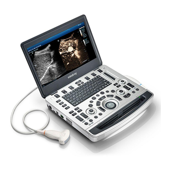
Product Specifications Introduction 2.1.1 Intended Use The diagnostic ultrasound system is intended for use in clinical ultrasonic diagnosis. 2.1.2 System Appearance Product Specifications 2-1…
-
Page 20
Name Function Monitor Displays the images and parameters during the scan. Control Panel Operator-system interface or control Handle Used for carrying the system Power input port Connects the power adapter HDMI port Outputs high definition multimedia signals USB port Connects USB devices (2 ports) ECG port Connects ECG lead or DC-IN cable Connects a probe to the main unit;… -
Page 21
Perform the plug and unplug of the probe module. To reduce the wastage of probe Note: module, the operation should be conducted under frozen status of the system. If you use the probe extend module to connect a probe, the image quality may be degraded. -
Page 22
2.1.2.2 Control Panel 2-4 Product Specifications… -
Page 23
No. Name English Name Description B mode button Press to enter B mode P mode button Press to enter Power mode. C mode button Press to enter the Color mode. CW mode button Press to enter CW mode. PW mode button Press to enter the PW mode. -
Page 24
No. Name English Name Description Press to clear off the comments or Clear button Clear measurement calipers on the screen. Freeze button Freeze Press to freeze or defreeze the image. Power button Power button Press to select the soft menu items Soft menu adjustment displayed on the bottom of the screen. -
Page 25
No. Name English Name Description Body mark button Body Mark Press to enter/ exit the body mark mode. Cursor button Cursor Press to show/hide the cursor Baseline position adjustment button Baseline Adjust the baseline parameter. auxiliary interface Scale adjustment button and auxiliary Scale Adjust scale parameter. -
Page 26
No. Name English Name Description Battery status indicator. Charging status: It illuminates in orange when batteries are charging; It illuminates in green when batteries are charged to full capacity; Battery indicator Discharging status: It illuminates in green when batteries are charged fairly;… -
Page 27
No. Name English Name Description Moves the cursor one letter each time; or, Direction-control keys select the ambient one in a selectable area. User-defined keys, functions of which can User-defined key 4 be defined in preset. Alphanumeric keys Enter characters. For functions of undefined buttons or keys, the user can define it on your own. -
Page 28: Trolley Appearance
2.1.3 Trolley Appearance 2-10 Product Specifications…
-
Page 29
Name Function <1> Probe cable hook Manage probe cable <2> Ultrasound main unit Ultrasound system <3> Ascending/descending switch Press to adjust the height of operation panel <4> Anti-theft setting Used to fix the ultrasound system to the trolley. <5> Printer bracket Used to place the printer <6>… -
Page 30
Name Function <13> Moveable hook Manage probe cable <14> Storage box Used to place report or other stuff. Used to offer output/input port, equipotential terminal <15> Power supply panel for power supply. Battery indicator: It illuminates in orange when batteries are charging;… -
Page 31: Peripherals Supported
Be sure to connect the equipotential wire before inserting the power plug into the receptacle; be sure to pull out the power WARNING: plug from the receptacle before disconnecting the equipotential wire; otherwise electric shock may result. When you connect another device to this system, you should use the equipotential wire to connect each of equipotential terminals;…
-
Page 32: Specifications
Specifications 2.2.1 External Dimensions and Weight Size: (362±5) X (390±5) X (59±3) mm Weight (built-in battery assembly): < 6.5KG 2.2.2 Electric Specifications 2.2.2.1 AC IN Main unit 100-240V~ (for adapter) Voltage 50/60Hz (for adapter) Frequency 2.0 A max (for adaptor) Output power Trolley…
-
Page 33: Environment Specifications
2.2.3 Environment Specifications Operational Conditions Storage Transportation Conditions 0℃-40℃ -20℃-55℃ Ambient temperature 30%-85% (no condensation) 20%-95% (no condensation) Relative humidity 700hPa-1060hPa 700hPa-1060hPa Atmospheric pressure Do not use this system in the conditions other than those WARNING: specified. 2.2.4 Monitor Specifications Working voltage 15.6 inches;…
-
Page 35: System Installation
System Installation Installation Preparations Do not install the machine in the following locations: Note: Locations near heat generators Locations with high humidity Locations with flammable gases 3.1.1 Electrical Requirements 3.1.1.1 Requirements of Regulator See Chapter 2.2.2 for power supply specifications. Due to the difference of the power supply stability of different districts, please advise the user to adopt a regulator of good quality and performance such as an on-line UPS.
-
Page 36: Installation Condition
3.1.2 Installation Condition 3.1.2.1 Space Requirements Place the system with the necessary accessories at a proper position for convenient use. Place the system in a room with good ventilation or having an air conditioning unit. Maintain a generous – free air flowing space around the back and both sides of the system; failure may result due to increased rise in system operating temperature.
-
Page 37
Take out the wooden cover. Unpacking Remove the box upwards if the space is commodious enough; If the space is not commodious enough, please follow the instructions below: Press the middle of plastic clasp on the one side of the box as shown below; Pull out the plastic clasp;… -
Page 38
Take out the plastic clasp out of the box (5 plastic clasps); Take off the plastic clasps to open the box. Take out the foam of M9’s top plate. Take out the auxiliary box. 3-4 System Installation… -
Page 39
Take out foam lifting of the trolley. Take out the fixing board Turn the wooden cover to a slope. Push the trolley down over the wooden slope. System Installation 3-5… -
Page 40
3.2.1.2 Unpack Main Unit Cut off four tapes of the external package, open the external box, and take out the auxiliary box and fixing foam; Take out the trolley case. Unlock the clasp to open the trolley case. Take out the main unit and adaptor. Take out other attachments 3-6 System Installation… -
Page 41: Check
1. After unpacking, check the objects in the container with the package list to see if anything is in short supply or is wrong. 2. Inspect and make sure there is no damage to the machine, no indentation, no cracks. If there is, please contact Mindray Customer Service Department. Installation of Whole Device 3.3.1 Connecting Power Cable Connect the connector of the power adapter to the adapter port in the system.
-
Page 42: Installing Peripherals
Toggle the locking lever to the top position. Place the probe properly to avoid being treaded or wrapping with other devices. DO NOT allow the probe head to hang free. Installing Peripherals Please see Chapter 2.1.4 for the device model that the system supports. 3.4.1 Connecting the Footswitch The system supports footswitch of USB port type.
-
Page 43
As shown in the figure below, a graph / text printer has a power cord and data cable. The power cord shall be directly plugged into a well-grounded outlet. 1. Connect the data cable to the USB port on the ultrasound system. 2. -
Page 44: Video Printer
Report print In Report screen, select [Print] to print the report. If you want to use a shortcut key for report print, you need to define the user-defined key in “Key Configuration”. For details, see Operator manual. Please refer to the accompanying manuals of the printers for more details. 3.4.4 Video Printer The system support video printers, consist of the B/W digital printers and color digital printers.
-
Page 45: Barcode Reader
(4) Click [OK] to return to the page. (5) Select the target printer from the drop-down list in the “Property” box and set other printing properties. (6) Click [Save] to complete. 3.4.5 Barcode Reader The system supports barcode reader to read the patient information (ID). 3.4.5.1 1-D Barcode Reader The appearance of barcode reader.
-
Page 46
Connecting terminal of connecting cable Press scan trigger button to receive barcode when ultrasound device is running (without installing driving program). For more operation details, see relevant barcode reader manual. 3.4.5.2 2-D Barcode Reader Install the connecting cable The appearance of barcode reader. Each part of the barcode reader: LED indicator, scan window and scan trigger button. -
Page 47
Using the tip of a screwdriver or some other tools with a sharp head, depress the cable’s modular connector clip. Carefully slide out the cable. System Installation 3-13… -
Page 48: Wired Network Connection
Wired Network Connection Connect the USB plug of the USB to LAN Adapter to the USB port on the machine, and insert the network cable into the LAN port of the adapter to get a wired network connection. The LAN port of the adapter CAN ONLY be used to connect to wired network. WARNING Device interconnection using the adapter through LAN port is forbidden;…
-
Page 49: System Preset
3.6.3 System Preset Press [Setup]. Setup menu appears. Click [System Preset] to enter System Preset interface. System Installation 3-15…
-
Page 50: Print Preset
The following settings can be performed on the System Preset interface. Preset Interface Description To set the hospital name, language, time zone, system time format, system Region date format and system date/time. To set patient information, exam setup, patient management, image storage, General display, system dormancy, etc.
-
Page 51: Network Preset
Print service setting Add Service: click to add print service. Remove Service: click to delete the selected print service. Rename Service: click to rename the selected print service. Default print service: click to set the selected print service as the default one. Set Service Property: to preset the service property, such as paper size, paper orientation, etc.
-
Page 52: Network Configure
Name Description Service Name The name of the iStorage service. IP Address IP address of the iStorage service device. Port Port for transmitting. Connect Click to verify connection. Click to add the Network service to the service list. Update To save the changed parameters. Delete Click to delete the selected service from the service list.
-
Page 53
2. Roll the trackball and press <Set> to select the target network, click [Connect] to connect to the network. When connecting an encrypted network, enter the password in the box first.You can select to hide password characters or not. 3. The system tries to connect and the wireless manager icon turns into . -
Page 54: Dicom/Hl7 Preset
3.6.7 DICOM/HL7 Preset Only if DICOM basic option is configured, [DICOM Preset] is available. Note: Click [DICOM Preset] to enter the DICOM Preset interface. Set DICOM service attributes first: enter AE Title (use Application Entity title for ultrasound system), terminal and package size. Server setting Enter the device name and the IP address;…
-
Page 55: System Information Verification
When the system is configured with DICOM basic function module, and installed DICOM Worklist, storage commitment, and Query/ Retrieve modules, the corresponding preset settings can be found in DICOM Service screen. The DICOM Service Setting is used to set properties of DICOM services. See the basic volume for details.
-
Page 57: Product Principle
Product Principle General Structure of Main Unit’s Hardware System Figure 4 — 1 Schematic diagram of system hardwareThe general structure of M9’s hardware system is shown in figure above. M9 system hardware consists of each following part: Main board DC-DC circuit, which offers power supply, charges or discharges the battery.
-
Page 58: Main Board
TRA FPGA is the FPGA which controls the transmission and the receiving. 65-128 transmitting/receiving channels. Control interfaces related to probes. 4D&TEE functional circuit implements functions of 4D drive circuit and TEE temperature measure, etc. Power supply management (EC) implements functions of the power supply management and control of starting/shutting down the main unit.
-
Page 59: Power Supply
4.2.1 Power Supply 2.5A Chg Charger 4.6A Dsg 2.5A Chg Charger 4.6A Dsg 19.0V/7.9A DCDC 1.2V 1.5V 12VBUS Buck AC/BAT (12A) 3.3V PWR_12V_EN_N DCDC (240mA) 3V3STB(100mA) DCDC 5VSTB(500mA) DCDC DCDC 5VSTB_EN Figure 4 — 2 Principle diagram of power system Function description: It provides the power to start the device and the power when the main unit is in standby.
-
Page 60
Function description: Circuit Unit Function The control for Takes charge of starting and shutting down the device and Starting and controls the indicator for starting and shutting down the shutting down the device device System monitoring Takes charge of battery management, fan control, voltage detection, battery indicator control, voltage detection and temperature detection Wireless net… -
Page 61: Front-End Of Main Board
4.2.3 Front-end of Main Board Pencil Main board transmitting and receiving probe PEN_RX Pencil receiving probe switch High- Connect to Transmitting Low- 64ch TX,64ch voltage 64ch control voltage probe via pulse drive TR 64 output circuit circuit board Signal process FPGA RX, control 64ch High- AFEclip 64ch voltage FPGA Control TR …
-
Page 62: Tr64 Board
TR64 Board Pencil TR64 board PEN_TX probe transmitting Main switch transmitting Main board board power 65-128 supply 65-128 High- Transmitting TX,64ch 1-64 voltage 64ch Drive control Probe pulse circuit board output circuit FPGA Data RX, AFEclip 64ch 64ch High- voltage FPGA isolation Clock Control…
-
Page 63: Phv Power Supply Board
Implements the switch of 192 array probe within the probe. Probe board only supports channel. PHV Power Supply Board Figure 4-6 Diagram of PHV power supply board Function description: PHV power supply board is the board that provides the power to the transmitting circuit. AP100V, AN100V, PHV1P, PHV1N, PHV2P, PHV2N, CW_PWR_P and CW_PWR_N are all outputs.
-
Page 64
Then, it starts scan transmitting. ECG transducer can be connected externally in this module design, which is also compatible with other monitoring products manufactured by Mindray.ECG unit structure is shown as below: Figure 4-7 Principle diagram of ECG board… -
Page 65: Control Panel
Control Panel Control panel unit includes two boards, as shown below: Board Description on Board Function Name Control LCD monitor folding/unfolding detection, power button, trackball, standard Panel keys on keyboard, user-defined functional keys, backlight control, status indicator of the device, encoder, buzzer, TCG detection, etc. TCG adjustments in 8 segments Board Trackball…
-
Page 66: Main Display Unit
TGC board implements the fix of TCG’s sliding rheostat. Trackball sub-module communicates with the host via USB. Sub-module of QWERTY keyboard adopts “thin film + silicon keys + structure keys” to implement the standard keyboard. Buzzer sub-unit adopts PWM waveforms that FPGA outputs to control the length and sound of volume and frequency.
-
Page 67: Probe Extension Board
Probe Extension Board Probe Extend Board 260PIN Aprobesocket probe 260pin Probe Board connector Probecontrolsignal CPLD Bprobesocket 260pin Probesignal Cprobesocket Probecontrol 260pin circuit 12V/5.7V /+100V/-100V 128channel POUTsignalswitch Transmitting/receivingsignal (relayset) 4D&TEEsignal Ultrasoundsignal 4D&TEEsignal switch Communication (relayset) &control Powersupply Figure 4-9 Hardware diagram of probe extension board Function description: Supports 192/128 array probe, 4D probe, phased array probe, bi-plane probe, and other nominal probes, etc.
-
Page 68: Audio/Video Transfer Module
RGB video signal, NTSC, S-Video signal with format of PAL. M9 audio/video transfer module includes: power supply, HDMI signal receiving, digital video signal processing, and audio/video code. Figure 4-11 Diagram of audio/video extend module…
-
Page 69: Usb Hub Board
4.11 USB HUB Board USB main port Repeater/Controller USB sub-port USB sub-port Fig 4-12 Principle diagram of USB HUB board The main functions of USB HUB board: Compatible with the USB 2.0 standard; One USB port can be subdivided for four USB ports (there are two ports in current products.) Detect the plug and unplug of USB device via main port.
-
Page 70: Connection Board Of Trolley Power Supply
Figure 4-13 Diagram of related boards of trolley power supply 4.12.1 Connection Board of Trolley Power Supply Main functions of connection board of trolley power supply: AC input transfer Auxiliary output control. Auxiliary output is enabled after starting main unit. Auxiliary output disconnects when main unit is in standby or shuts down.
-
Page 71: System Power-On Control
Principle diagram of management board of trolley battery is shown below: Figure 4-14 Diagram of management board of trolley battery 4.13 System Power-on Control Figure 4-15 System power-on diagram Description of related controlling signals: Controlling signal Description Comme PWR_BTN_N, Pulse signal that power-on button of control panel produces passes to CPU board through FPGA, PWR_BTN# and is used for starting the device.
-
Page 72
The signal is not used currently PWR_OK# Sent out by power management FPGA to CPU board, indicates that the 12V is powered on. Power supply of main unit/battery enables the start of device. Power supply produces 5VSTB and 3.3VSTB as the AC inputs. Unplug AC when shutting down the device. -
Page 73: Internal Connection Diagram Of Main Unit And Trolley
2*40 USB HUB board board 1PCBA board PCB Trolley LED board Probe extend module Probe connecting AC-DC module 2*40 board 2PCBA M9 probe extender M7 probe extender B connecting 2*20 4DConnecting board probe PCBA AC output Battery 1*11 Trolley battery…
-
Page 74
LVDS data to monitor(BIOS boot screen) COME module, No sign on complete BIOS monitor LOGO Hard disk Start loading OS (MINDRAY) indicator, Display changes displays on green, blinks of resolution monitor No sign on Complete OS monitor loading Image from… -
Page 75: Checking Performance And Functions
Checking Performance and Functions Description The chapter describes checking methods to main functions and performance. The methods are only for reference. Checking System Status 5.2.1 Running Status Power on/off normal (duration time is normal), no abnormal sounds or occasion occur during normal operation.
-
Page 76: General Check
General Check 5.3.1 Check Flow Check the control panel Check the monitor Check peripherals Check ECG Check I/O port 5.3.2 Check Content 5.3.2.1 Check Control Panel Procedure Checking criteria 1. Check all buttons, keys and knobs All keys and knobs are effective. Follow the direction: left to right, and up to down.
-
Page 77
5.3.2.2 Check Monitor Procedure Checking criteria Height adjustment: Monitor brightness adjustment Auto adjustment: select [Preset]-[System Monitor contrast adjustment Preset]-[General]. Click [Brightness Auto Monitor maintenance Adjustment] from [About]. Log on with the account named as Manual adjustment: press <Fn>+< > to increase “Service”, select the brightness. -
Page 78
5.3.2.3 Checking Peripherals Procedure Checking criteria Footswitch: confirm the normal connection Trigger the freeze key of the footswitch (right key). between footswitch and USB port. Check Image freeze menu and freeze menu appear. The the configuration status of footswitch under image is unfrozen if the key is triggered again. -
Page 79: Functions Checking
Functions Checking The chapter lists the system checking items with complete configurations and Note: describes them in details. If the items are not configured, the relevant tests can be ignored. 5.4.1 Checking Flow 5.4.2 Checking Content 5.4.2.1 Imaging Mode B-mode In B mode scan, the image parameter area in the upper left corner of the screen displays the real-time parameter values as follows: Items…
-
Page 80
Parameter Adjustment Procedure Checking criteria Press <B> button. Enter B mode image. B mode interface appears. Frequency adjustment The real-time value of frequency is displayed in the image parameter area in the upper right corner of the screen B image soft menu-[Image (fundamental wave-F, Harmonic frequency-H ). -
Page 81
Persistence The system provides 7 level of persistence. The bigger the value image soft is the stronger the effect becomes. menu-[Persistence]. Rotation/Invert To invert the image horizontally or vertically. image soft menu-[L/R Image can be rotated by the angle of 0°, 90°, 180° and 270°. Flip]/[U/D Flip]. -
Page 82
Images corresponding to four groups of parameters are displayed on the soft menu (from left to right). B image soft menu-[LGC]. Click [LGC1-5] to adjust the parameters. To each segment of image area, the system offers 5 values to adjust the gain. The gain increases with the value becoming bigger. -
Page 83
Parameters that can be adjusted to optimize the Power mode image are indicated in the following. Adjustment Parameter Item Control panel and soft Gain, Map, Dynamic Range menu adjustment PW / CW Mode In PW/ CW mode scan, the image parameter area on the right side of the screen displays the real-time parameter values as follows: Parameter Angle… -
Page 84
5.4.2.3 Cine Review Procedure Checking criteria Press <Freeze> to freeze the image. The system enters manual-review. (Precondition: Set “Enter in frozen status” Enter Cine Review status to “Cine”. The system enters auto review status. Open cine files in thumbnail, iStation or Review. -
Page 85
5.4.2.5 Image and Imaging Management Procedure Checking criteria Press <Save> in scan process (set based on the Save B mode image to patient data library in preset) real-time. The icons of the images appear on the right side of the interface. Select [Preset]-[System Preset]-[General]. -
Page 86: Performance Test
Performance Test 5.5.1 Test Procedures 5.5.2 Test Content The following figure is only used for reference in the testing, and the actual Note: image effect depends on the specific system. Requirements: Display: set the brightness and contrast values to clinical (or default) status; Ambient: dark room to simulate actual clinical using;…
-
Page 87
Read the separation between two target points that can be distinguished clearly, while keeping the transverse target group horizontal. Repeat upper steps at other depth. Image effect is show in figure below: Axial resolution Test Procedure: Place the probe head gently on the acoustic window of the phantom which is covered by water or gel, and make sure the axial resolution targets are displayed in the center of the image. -
Page 88
For convex probe, keep the lateral resolution targets near the central line of the Note: scanning plane. For linear probe with Steer function, DO NOT turn on Steer when testing the transverse resolution. Magnify (zoom) the targets for observation if necessary. Distance between the left and right edges of a target point at a certain depth indicates the transverse resolution at this depth also. -
Page 89
5.5.2.3 Geometric Positioning Accuracy Axial Geometric Positioning Accuracy Test Procedure: Adjusting steps are the same with the Maximum Detection Depth. Record the separation values with measuring caliper in step of 20 mm on the axial target group. Select all measurement values deviating largely from 20 mm, and calculate the error by the following formula. -
Page 90
Lateral Geometric Positioning Accuracy Test Procedure: Place the probe gently on the acoustic window of phantom which is covered by water or gel. Adjust display depth, to make horizontal groups display in the image. Adjust focus to be in horizontal groups (no explicit standard). Adjust gain, TGC, etc to make horizontal groups display clearly. -
Page 91
5.5.2.4 Blind Area Test Procedure: Place the probe gently on the phantom surface which is covered by water or gel. Adjust the depth to lower value and set the focus to shallowest. Reduce AP, Gain, etc until the background noise is barely visible. Observe the depth of shallowest target image. -
Page 93: Software Installation & Maintenance
Software Installation & Maintenance Enter Maintenance Before the maintenance operation, the engineer should login the system as Service. Note: Log-in: When Access Control is disabled: press “ctrl”+“/” to pop up the Login dialogue box, select Service as the user name and input the password. When Access Control is enabled, press “ctrl”+“/”…
-
Page 94: Software Installation/Restoration
2. Do Not cut off, shut down or restart the system in the restoration. Enter Windows The password is generated by device Mac address and serial number (see System Information), please contact Mindray Service Department for details. Enter maintenance menu. Click [Enter Windows]. Type the password to enter Windows system.
-
Page 95: Data Backup And Storage
When the log is exported, the system prompts “Export succeed!”, click [OK] to return to Maintenance menu. The log can be exported to the external USB storage device only. Make sure Note: there is enough space for the storage before the exporting. Data Backup and Storage 6.5.1 Preset Data Management…
-
Page 96: Patient Data Backup And Restoration
StressEcho Protocol Template gui word User-defined library PATIENTDATA Patient database path Preset Current User preset data temporary Temporary file directory D:M9 ScreenSaver Screensaver crash Dump file directory DICOMRevFiles Temporary file backed up by DICOM Log Log file DcmLog DICOM log…
-
Page 97
Drive. E:M9 PatientBack Patient data backup Demo Demo file Software Installation & Maintenance 6-5… -
Page 99: Field Replaceable Unit
Field Replaceable Unit The chapter describes the detailed information of units, which can be replaced in the system scene. Field Replaceable Unit 7-1…
-
Page 100: Main Unit
Reference Used for old machine(LVDS output+miniPCIEport 115-023067-00 WiFi); Mark Software version, Includes button battery and radiator washer. M9 Main Board 8.2.10 For M9GI in CE (FRU) region.Used for old machine(LVDS output+miniPCIEport 115-033406-00 WiFi); MMark Software version, Includes button…
-
Page 101
Classific Picture Disassembl Model Material Name Order Number Remarks ation y Reference battery and radiator washer. Used for old machine (old PC+LVDS output); The MAC address will CPU Module change with the 115-023066-00 (FRU) replacement of CPU, so you may need apply the optional key the machine installed before. -
Page 102
Mark software version. NOTE: If SSD card is replaced, 115-024561-00 you need to select the SSD Card 8.2.5 For M9 in CE second installation series (M9/CE/FRU) region. method (2. Install system without keeping user’s data <format all disk>.) during OS recovery. -
Page 103
Classific Picture Disassembl Model Material Name Order Number Remarks ation y Reference 115-024561-01 SSD Card Aplicable for M9 with (M9/CE/FRU/610 For M9 in CE 6100 PC 0 PC) region. 115-024562-00 SSD Card For M9CV in (M9CV/CE/FRU) CE region. 115-024562-01 SSD Card… -
Page 104
Material Name Order Number Remarks ation y Reference 00 PC) region. 115-026788-00 SSD Card (M9CV/FDA/FRU For M9 in FDA region 115-026788-01 SSD Card Aplicable for M9CV with (M9CV/FDA/FRU For M9CV in 6100 PC in FDA region /6100 PC) FDAregion. 115-026789-00… -
Page 105
Classific Picture Disassembl Model Material Name Order Number Remarks ation y Reference 115-048923-00 SSD Card (M8Elite/FDA/FR For FDA region only For M8Elite in U/6100 PC) FDA region. Compatibility description: The vision of the 023-001226-00 software with 023-001226-00 wireless Wireless net net adapter: adapter(HalfMi niPCIE… -
Page 106
(FRU) PHV Power 115-023068-00 8.2.10 series Board(FRU) Power supply Power supply 022-000147-00 related series adapter M9 Li-ion battery FRU (For CE 115-023405-00 Includeing Two batteries, region) should be replaced 8.2.2 series M9 Li-ion battery together FRU (For FDA 115-023072-00 region) -
Page 107
Classific Picture Disassembl Model Material Name Order Number Remarks ation y Reference 115-023071-00 Not include trackball Control panel assembly,TGC board 8.2.6 series assembly (FRU) and keyboard 115-023071-01 (FRU/6100PC) Silicon keypad 049-000559-00 8.2.11 Control series panel related Short swing key 043-003222-00 8.2.11 series assembly… -
Page 108
Classific Picture Disassembl Model Material Name Order Number Remarks ation y Reference Not include the Trackball 023-000706-00 8.2.11 series connecting cable Not include the TGC Board 051-001383-01 8.2.11 series connecting cable 2116PC keyboard 043-008650-00 8.2.11 series (international) 801-2300-0000 Buzzer (FRU) 8.2.11 series 8-00… -
Page 109
Classific Picture Disassembl Model Material Name Order Number Remarks ation y Reference Monitor 115-023069-00 LVDS signal assembly (FRU) Monitor 8.2.12 series Assembly(eDP 115-048328-00 eDP signal screen/FRU) Used to repair monitor Monitor with LVDS signal; When Assembly(LVDS 115-048329-00 115-023069-00 is used 2eDP/FRU) up, apply Monitor… -
Page 110
Classific Picture Disassembl Model Material Name Order Number Remarks ation y Reference Stick the fan cladding to M9 FAN(FRU) 115-023074-00 8.2.8 series the fan on the scene. Back cover assembly of main 115-017214-00 One pair (2) series unit Speaker and… -
Page 111
043-003265-00 Dust-proof mesh of fan 8.2.3 series unit Right Damping 045-000885-00 8.2.12 series Shaft Left Damping 045-000884-00 8.2.12 series Shaft iDock51 Audio/Video 115-020783-01 9.2.3 series Extend Module M9 Travelling 115-039785-00 3.2.1.2 series case Field Replaceable Unit 7-13… -
Page 112
Classific Picture Disassembl Model Material Name Order Number Remarks ation y Reference M9 Ordinary 048-004129-00 3.2.1.2 series Probe Bag M9 Intracavity 048-004130-00 3.2.1.2 series Probe Bag 7-14 Field Replaceable Unit… -
Page 113: Mobile Trolley
Mobile Trolley Classi Disassembl Model ficatio Material Name Order Number Picture Remarks y Reference Gas spring 115-020353-00 UMT-500 assembly trolley 8.3.5 series USB-HUB 115-021103-00 assembly UMT-500 trolley 8.3.5 series Main Drawer lock 034-000353-00 unit relate UMT-500 trolley 8.3.5 series Trolley panel cover 115-020346-00 assembly UMT-500…
-
Page 114
Classi Disassembl Model ficatio Material Name Order Number Picture Remarks y Reference Caster (FRU) 115-015314-00 UMT-500 trolley 8.3.8 series Trolley power 024-000320-00 supply fan UMT-500 trolley 8.3.3 series Power supply 022-000148-00 Power board supply UMT-500 relate trolley 8.3.3 series Battery assembly 115-011471-00 One battery is used as the… -
Page 115
Classi Disassembl Model ficatio Material Name Order Number Picture Remarks y Reference the same Battery assembly 115-011472-00 time. (For FDA region) 8.3.3 Connection board 051-001386-02 of trolley power supply UMT-500 trolley 8.3.3 series Management 051-001387-02 board of trolley battery UMT-500 trolley 8.3.3 series… -
Page 116
Classi Disassembl Model ficatio Material Name Order Number Picture Remarks y Reference Probe holder and 115-037617-01 probe holder backet (FRU) 8.3.10 UMT-500 trolley series Intracavity probe 115-045239-00 holder and probe holder backet (FRU/Upgrade) 8.3.11 Probe cable hook 801-2102-00016-0 assembly UMT-500 (maintenance trolley 8.3.6… -
Page 117
Classi Disassembl Model ficatio Material Name Order Number Picture Remarks y Reference Trolley storage 043-003592-00 tray UMT-500 trolley 8.3.2 series UMT-500 Trolley Pallet trolley 043-003430-00 9.2.1 storage series UMT-500 Probe extend trolley 115-020784-00 9.2.2 module series Field Replaceable Unit 7-19… -
Page 119: Structure And Assembly/Disassembly
Structure and Assembly/Disassembly Structure of the Complete System 8.1.1 Main Unit Fig Overall Exploded View Name Name Display (monitor) assembly Hardware cover Control panel assembly Battery Machine board assembly Battery cover assembly Back cover assembly of main unit Structure and Assembly/Disassembly 8-1…
-
Page 120: Mobile Trolley 8
8.1.2 Mobile Trolley Name Name Trolley panel cover assembly Probe cable hook assembly Cast-aluminum base assembly of Storage tray trolley panel Power supply assembly Probe extender assembly Trolley base assembly Lifting column assembly 8-2 Structure and Assembly/Disassembly…
-
Page 121: Main Unit
1PK-H024 095-000063-00 4″ Diagonal cutting pliers N-206S 095-000077-00 Anti-electrostatic glove: 1 pair. 8.2.1.2 Engineers Required The disassembly should be performed by professionals from Mindray or the staff who are qualified for the maintenance after the training. Structure and Assembly/Disassembly 8-3…
-
Page 122: Battery
8.2.1.3 Disassembly Requirements Be prepared before disassembling ultrasound device. Stop scanning the patient and capturing images. Shut down the device and cut off AC power supply. Unplug AC power supply cable. Be prepared for a softer platform and keep the platform clear. Prevent the device from scrape. Get the tools and gloves prepared.
-
Page 123: Dust-Proof Mesh Of Main Unit
Battery 8.2.3 Dust-proof Mesh of Main Unit Take out the dust-proof mesh on the right side. Dust-proof mesh on the right side Take out the dust-proof mesh in front of main unit. Dust-proof mesh in front of main unit Structure and Assembly/Disassembly 8-5…
-
Page 124: Network Adaptor
8.2.4 Network Adaptor Unscrew four screws (M3 X 6 cross panhead screw) on the hard disk cover, and then remove the hard disk cover. Hard disk cover M3 X 6 cross panhead screw (4 screws) Extract the network cables. Extract the signal cables of monitor via black handle. Network adaptor snap closure Extract signal cables of monitor via black handle Push the metal snap closure backwards as the thick arrow shows.
-
Page 125: Ssd Card
Two metal snap closure to lock wireless network adaptor Metal snap closure Wireless network adaptor Remove button battery Hold the button battery gently. Put the sharp end of the tweezers or flat-headed screw into the gap between battery and bulges of plastic cover. The button battery bounces off then. Note: do not press hard in the operation.
-
Page 126: Control Panel And Monitor
Metal clasp Take out SSD card. 8.2.6 Control Panel and Monitor Remove network adaptor and battery assembly. See Chapter 9.2.2 and Chapter 9.2.3 for details. Unscrew 11 screws on the back cover (M3 X 8 Nylok screw). 8-8 Structure and Assembly/Disassembly…
-
Page 127
M3X8 Nylok screw (11 screws) Open control panel. Extract the signal cables of control panel, and remove the control panel. Extract signal cables of control panel Unscrew 4 screws (M3 X 8 Nylok screws) as shown in the Figure. Remove the monitor upwards. -
Page 128: Ecg Assembly
M3X8 Nylok screw Remove the monitor assembly upwards (2 screws for each left and right side) 8.2.7 ECG Assembly Remove control panel and monitor assembly. See Chapter 9.2.4 for details. Unscrew 4 screws on CG shield cover (M2 X 4 stainless steel cross head screws). Remove the shield cover.
-
Page 129
M2 X 4 stainless steel cross head screw (4 screws) Pressure plate ECG signal cables Unscrew 2 screws on ECG fixing bracket (M3 X 8 Nylok screw).Remove ECG’s fixing bracket and extract ECG connecting cables. M3 X 8 Nylok screw (2 screws) Connecting cables to ECG socket ECG fixing bracket… -
Page 130: Fan
Remove the speaker assembly. Unplug the socket on the main board. Socket to speaker Speaker assembly 8.2.8 Remove control panel and monitor assembly. See Chapter 9.2.4. Unplug the connecting cable of fan. Remove the hot-melt adhesive. Take out the fan. Hot-melt adhesive Fan’s shield cover Fan plug…
-
Page 131
M2 X 4 stainless steel cross head screw (2 screws) Unscrew 3 screws on the fixing bracket of probe socket (M3 X 8 Nylok screw). M3 X 8 Nylok screw (3 screws) Take out the probe board assembly. Unscrew 4 screws on probe’s socket (M3 X 8 Nylok screw). Take out the probe’s socket. Structure and Assembly/Disassembly 8-13… -
Page 132
Probe board M3 X 8 Nylok screw (4 screws) Probe socket Disassemble IO fixing bracket, fixing bracket of pencil probe structure. Unscrew 2 screws on IO fixing bracket (M3 X 8 Nylok screw). Take out IO fixing bracket. IO fixing bracket M3 X 8 Nylok screw (2 screws) Unscrew 2 screws on the fixing bracket of pencil probe (M3 X 8 Nylok screw). -
Page 133: Machine Board Assembly
8.2.10 Machine Board Assembly Remove control panel and monitor assembly. See Chapter 9.2.4 for details. Disassemble machine board assembly. Unscrew 11 screws (M3 X 6 cross panhead screw). Take out the machine board assembly. Machine board M3X6 cross assembly panhead screw (11 screws) Disassemble TR64 board Unscrew 7 screws on TR64 board (M3 X 6 cross panhead screws).
-
Page 134
M3 X 6 cross panhead screw (7 screws) TR64 board Disassemble PHV power supply board Unscrew one screw on grounding elastic sheet (M2.5 X 12 cross panhead screw) M2.5 X 12 cross panhead screw (1 screw) Grounding elastic sheet Unscrew 4 screws on larger shield cover of PHV board (M3 X 6 cross panhead screw). Remove the larger shield cover of PHV board. -
Page 135
M3 X 6 cross Larger shield panhead screw cover of PHV (4 screws) board Unscrew 1 screw on smaller shield cover of PHV board (M3 X 6 cross panhead screw). Remove the smaller shield cover of PHV board and PHV board. M3 X 6 cross Smaller shield panhead screw… -
Page 136: Control Panel Assembly
M2.5X12 cross slot bolt (4 screws) NOTE Do not open the BIOS base shown in the following figure when disassembling the CPU board assembly. Ensure the BIOS base is closed before re-assembling the CPU board assembly. Press it until closed if it is opened. Otherwise, it fails to boot the device up.
-
Page 137
M3 X 6 cross slot screw (4 Flexible PCB screws) Remove the water-proof plate of standard small. Water-proof plate of standard small Unscrew 6 screws locking the standard keyboard. Take out the small keyboard upwards. Structure and Assembly/Disassembly 8-19… -
Page 138
M3X6 cross slot screw (6 screws) 3. Remove the caps on the control panel. Pull out the cap upwards. Caps for: small encoder button (Zoom), TCG cap (8 caps), large encoder button (Auto Correct), large encode button (iTouch). Large encoder Large encoder Small encoder button (Auto… -
Page 139
Unscrew 2 screws locking the buzzer (M2 X 6 cross panhead screw). Unplug the connecting cables of the buzzer from PCB board, and remove the buzzer. M2 X 6 cross panhead screw with pad (2 screws) Connecting cable of buzzer 5. -
Page 140
M3 X 20 cross panhead screw (2 screws) Connecting cable of trackball 6. Disassemble TGC board Unscrew 4 screws on TGC board (M3 X 6 stainless steel cross panhead screw). Unplug STC connecting cables. Remove TCG board. M3 X 6 stainless steel cross STC connecting cable panhead screw (4 screws) 8-22 Structure and Assembly/Disassembly… -
Page 141
7. Disassemble the control panel PCBA Unscrew 20 screws (M3 X 6 stainless steel cross panhead screw) on control panel PCBA. Remove control panel PCBA. M3 X 6 stainless steel cross panhead screw (20 screws) 8. Disassemble caps Remove button caps on the control panel. Disassemble button caps 9. -
Page 142
Unscrew 4 screws (M3 X 6 cross panhead screw, 2 screws for each left and right side) from magnetic induction clip. Take out the magnetic chip. Unscrew 2 screws (M3 X 6 cross panhead screw, 1 screw for each left and right side) from status indicator. Take out the status indicator. M3 X 6 cross panhead Status M3 X 6 cross panhead… -
Page 143: Display (Monitor) Assembly
TGC dust-proof cover TGC board Silicon bearing (4 bearings) 8.2.12 Display (monitor) Assembly Remove the monitor assembly. See Chapter 9.2.4 for details. 2. Disassemble front cover of the monitor. Take out 4 screw caps from 4 corners of the monitor. Unscrew four screws inside. Note: keep screw caps properly.
-
Page 144
Take out the front cover form both sides 3. Unscrew 1 screw on the cable harness (M2.5 X 5 cross slot screw), and remove the cable harness. Take out the cables from channel. M2.5 X 5 cross slot screw (1 screw) Cable harness 4. -
Page 145
5. Disassemble light sensor board Unscrew 2 screws on light sensor board (M2.5 X 4 cross panhead screw). Take out the light sensor board. M2.5 X 4 cross panhead Light sensor board screw (2 screws) 6. Disassemble LCD Monitor Unscrew 6 screws from LCD monitor’s six corners (M2 X 4 cross panhead screw), and remove LCD monitor. -
Page 146
M2.5 X 5 cross slot screw (6 screws, 3 screws for each left and right side 8. Disassemble the magnetic snap closure of the monitor. Unscrew four screws on the magnetic snap closure (M2.5 X 4 cross panhead screw, 2 screws for each left and right side), and remove the metal part and the magnet. -
Page 147: Trolley Assembly/Disassembly
Anti-electrostatic glove: 1 pair. 8.3.1.2 Engineers Required The disassembly should be performed by professionals from Mindray or the staff who are trained to be qualified for the maintenance. 8.3.1.3 Disassembly Requirements Be prepared before disassembling ultrasound device. Stop scanning the patient and capturing images. Shut down the device and cut off AC power supply.
-
Page 148: Power Supply Assembly
Storage box Unscrew 2 screws on bracket of storage box (M4 X 12 cross panhead screw), and remove the bracket of the storage box. M4X12 cross panhead Bracket of storage box screw (2 screws) 8.3.3 Power Supply Assembly Unscrew 2 screws (M4 X 12 cross panhead screw) on the front of the main unit, and then disassemble 2 screws (M4 X 12 cross panhead screw) on the back of the main unit.
-
Page 149
Metal handle of power supply M4X12 cross panhead M4X12cross panhead assembly screw (2 screws) screw (2 screws) Remove dust-proof mesh Press the clip outwards (arrow 1). Pull out the plastic clasp towards the arrow 2’s direction. Clip The plastic clasp Remove the battery Unscrew 3 screws (M4 X 12 cross panhead screw) on the battery baffle board. -
Page 150
M4X12corss panhead screw (3 screws) Battery Remove the battery compartment and battery management board Unscrew 6 screws (M4 X 12 cross panhead screw, 3 screws for each left and right side) on the battery compartment, and then take out the battery compartment. M4X12cross panhead screw (6 screws, 3 screws for each left and right side) Unscrew 6 screws (M3 X 8 cross panhead screw) on the battery management board, and then remove the battery management board. -
Page 151
Unscrew 4 screws (M4 X 8 cross panhead screw) on AC-DC supporting board, and take out AC-DC assembly. M4X8 cross panhead screw (4 screws) Unscrew 4 screws (M4 X 8 cross panhead screw) on the back of AC-DC supporting board, and take out AC-DC power supply board. -
Page 152: Trolley Panel Board Assembly
M4X16 cross panhead with the pad and the clip (4 screws) 8.3.4 Trolley Panel Board Assembly Unscrew 10 screws (M4 X 12 cross panhead screw) on the back of trolley panel’s base, and take out the panel cover. M4X12 cross panhead screw (10 screws) Remove the rotatable clasp Unscrew 2 screws on the fixing bracket for the spring (M4 X 12 cross panhead screws), and…
-
Page 153: Spring Assembly
Fixing bracket for the spring M4X12 cross panhead screw (2 screws) Unscrew 2 screws (M4 X 12 cross panhead screw) on the fixing base of the pivot, and remove the fixing base of the pivot, then take out the rotatable clasp. Fixing base of M4X12 cross panhead the pivot…
-
Page 154
M4X12 cross M4X12 cross M3X8 cross M3X8 cross panhead screw panhead screw panhead screw panhead screw (2 (1 screw) (2 screws) (4 screws) screws) Remove the drawer lock. Unscrew the screws on the drawer lock. Remove the connecting plate between the screw and the key lock. -
Page 155
Hexagon screw Drawer lock Remove spring cable Remove the fixing bracket of spring cable Unscrew 2 screws (M4 X 12 cross panhead screw) on the base, and take out the bracket of spring cable. The socket of Fixing bracket of M4X12 cross panhead spring cable Trolley base… -
Page 156
Gas spring Handle Unscrew 2 screws (M4 X 12 cross panhead screw) on the injection-molding clasp of spring cable on the base. M4X12 cross panhead screw (2 screws) Unscrew 2 screws (M4 X 12 cross panhead screw) on the base of control panel, and take out the panel cover. -
Page 157
Take out the spring cable M4X12 cross panhead upwards screw (2 screws) Remove the connecting rod of gas spring. Press gas spring button (the sixth step), remove the handle upwards. Release the spring to the maximum length (operable to remove gas spring assembly). Put the auxiliary tool (M5 screw or screw driver) into the spacing hole on the back of the device (operable to remove trolley panel board). -
Page 158
M4X12 cross panhead screw (2 screws) Lift up the connecting rod of gas spring, and take out the spring of the connecting rod, then remove the connecting rod towards arrow’s direction. Remove the connecting rod towards arrow’s direction Spring of the connecting rod Remove gas spring Unscrew 6 screws (M5 X 25 Allen screw with the pad and the clip) on the connecting base of the gas spring. -
Page 159: Cast-Aluminum Base Of Trolley Panel
M5X25 Allen screw with the Connecting base pad or the clip (6 screws) Remove the latch of the gas spring at the bottom of the lifting column. Take out the gas spring upwards. Latch of Trolley base gas spring Gas spring 8.3.6 Cast-aluminum Base of Trolley Panel Remove the assembly of trolley panel cover and spring assembly.
-
Page 160
M5X25 inner head screw Cast-aluminum base of with the pad and the clip (8 trolley panel screws) Remove the printer tray Unscrew 4 screws (M4 X 12 cross panhead screw) on the printer tray, and take out the printer tray. M4X12cross panhead screw (4 screws;… -
Page 161: Lifting Column
M4X12 cross panhead Cable hook (one Holder bracket screw (10 screws) for each left and (one for each left Base of right side) and right side) probe holder 8.3.7 Lifting Column Remove cast-aluminum base of trolley panel. See Chapter 9.3.2.5 for details. Lay the device flat.
-
Page 162: Trolley Base Assembly
M6X16 Allen screw with External lifting column the pad and the clip (8 screws) Remove the straight track. Unscrew 8 screws (M5 X 12 Allen screw with the pad and the clip) on internal lifting column, and take out the straight track. M5X12 Allen screw with the Straight track pad and the clip (8 screws)
-
Page 163
M3X8 cross panhead screw (2 M5X25 Allen screw with the screws) pad and the clip (3 screws) Remove the casters Unscrew the hexagon screw between the casters and the base with dedicated jig. Cast-aluminum base Unscrew the screws Caster Remove metal strips Unscrew 14 screws (M4 X 12 cross panhead screw) at the bottom of cast-aluminum base. -
Page 164
Strip of power M4X12 cross supply box (one panhead screw piece for each left (14 screws) Front pegboard Back pegboard and right side) Remove the decorative cover of the base. Unscrew 4 screws (M3 X 8 cross panhead screw) on cast-aluminum base. Remove the decorative cover upwards. -
Page 165: Installation Of Probe Holder
8.3.9 Installation of probe holder 1. Two hooks of probe holder are inserted into holder bracket diagonally. 2. Press the probe holder inward as well as downward at the same time. 3. Stuff two screws behind the holder bracket (cross panhead screw M3X6) Structure and Assembly/Disassembly 8-47…
-
Page 166: Disassembly Of The Probe Holder
Fasten two cross panhead screws M3X6 8.3.10 Disassembly of the probe holder Disassemble the probe holder and three screws (M4X12 Philips pan headed screws) connected with the base of control panel, then remove the probe holder and holder bracket as a whole. NOTE: Don’t remove those two screws (cross panhead screw M3X6) of probe holder and holder bracket.
-
Page 167: Disassembly Of Intracavity Probe Holder
Unscrew M4X12 Philips Pan headed screws (3pcs) 8.3.11 Disassembly of intracavity probe holder 1. Disassemble intracavity probe holder Pull out the intracavity probe holder as the arrow’s direction. Intracavity probe holder Structure and Assembly/Disassembly 8-49…
-
Page 168
2. Disassemble intracavity probe holder bracket Unscrew two screws (cross panhead screw M3X12) Intracavity probe holder bracket cross panhead screw M3X12(2pcs) 3. Disassemble padding block Unscrew two screws (cross panhead screw M3X12) Padding block Cross panhead screw M3X12(2pcs) 8-50 Structure and Assembly/Disassembly… -
Page 169: Installation Of Option Modules
Installation of Option Modules Installation of Optional Devices to Software Install Copy optional key file to USB flash disk and plug USB flash disk to the port. Open [Preset] menu. Click [Maintenance]-[Option]. Select the software package to be installed from the list. Click [Install].
-
Page 170
The optional assembly is limited to single key. If the module is installed or there are 2 or more than 2 groups of the modules are selected, the installation Note: button appears dimmed and disabled. After all modules are installed, please go to the previous interface to confirm. Promote Click [Promote]. -
Page 171: Installation Of The Accessory Kits And Optional Devices To Hardware
Note: it is unavailable to use promotion for multiple optional keys. For the optional key which is promoted, it can also be installed. The installation to promotion key is same with these in Chapter 9.1 Install above. Uninstall 1. Select the software package to be uninstalled from option list. Click [Uninstall] and it pops up the [Confirm] dialogue box.
-
Page 172: Storage Tray
9.2.1 Storage Tray Remove the storage tray downwards. Take out the tray. Remove the storage tray downwards. Take out the tray 9.2.2 Probe Extender Assembly Unscrew 4 screws (M4 X 12 cross panhead screw) on the pegboard of probe extender assembly.
-
Page 173: Audio/Video Extender Assembly
Install the assembly towards arrow’s direction Figure 9 — 2 Screw 2 screws (M4 X 12 cross panhead screw) on the back of probe extender assembly. M4 X 12 cross panhead screw (2 screws; one screw for each left and right side) Figure 9-3 9.2.3…
-
Page 174: Trolley Installation
Metal clip Audio/video extender assembly 9.2.4 Trolley Installation The service staff installs the trolley according to the following steps after receiving the package: Open the package. See Chapter 3.2.1.1 for details. Install the holders on right and left sides. As shown in the following figure a) and b), place the probe holder into the holes of the left and right plate of the trolley.
-
Page 175
Holder on left side Holder on right side Figure 9-4 Installation for holders on right and left sides Install cable hook As shown in figure 1, aim the installation axis’s rabbet of probe hook assembly at the screw of fixing base, and then insert the probe hook assembly to the fixing base. Rotate the assembly anticlockwise to fix it (see figure b).The probe holders that are installed are shown in figure c. -
Page 176
Rotate probe hook assembly Probe hook assembly anticlockwise Screw Fixing base Figure 9-5 -Installing probe hook assemblyInstall storage tray. See Chapter 0 for details. Install the option modules if there are relevant modules for options: probe extend module, audio/video extend module. See Chapter 9.2.2 and Chapter 9.2.3 for details. 9-8 Installation of Option Modules… -
Page 177: System Diagnosis And Support
System Diagnosis and Support 10.1 General Status Indicator 10.1.1 Indicators of Control Panel Status indicators Icon Status definition and indicators Power-on status Off: System turned off; indicator The indicator blinks green when pressing the key. After powering on, the indicator is green. Battery status 1 It illuminates in orange color when batteries are charging;…
-
Page 178: Status Of Whole Machine
The brightness of the When you press any keys monitor keeps the same; on the control panel, the system would return to the The logo “mindray” moves There is no operation for the frozen status, the around the screen. Scree…
-
Page 179: Get Whole Machine Started
10.2 Get Whole Machine Started Power-on to the Press power button on machine control panel Power-on indicator is Temporary black screen Power-on completes. BIOS starts. BIOS start-up graphics appears 1.Backlight of control panel is on. 2.Power status indicators of IO back board are on. Windows operating system 3.The fan starts running.
-
Page 180: Power-On Process Of Whole Machine Supplied By Ac
The course of testing and hard The monitor appears in black screen now, and the time of the disk configuration course is short. The course of the internal core The logo “mindray” appears. loading The course of logging on Same as the above Starting DOPPLER The company logo appears, and simultaneously progress bar displays the related information.
-
Page 181: The Start-Up Of Doppler
10.2.4 The Start-up of Doppler 10.2.4.1 Procedure of Startup System Diagnosis and Support 10-5…
-
Page 182
10.2.4.2 Details of Procedures Possible reason for Step Procedures Increment Description starting stagnation Window start-up appmon starts Doppler Attach the path to configuration files Set Windows attributes Initialize display device, main interface, vocal, USB device representative Start bus device Backbone Dev and LPC Initialize the time and multi-language Start-up functions. -
Page 183: Alarming And Abnormal Information
The system has also alarming function, when the machine fails, it would pop up the alarming dialogue box, and simultaneously generate LOG file saved in the system log, which is saved in D disk: M9Log. Description: The asterisk “***” represents the time in LOG record. The format is: 2011-6-12 14:15:15 10.3.1 Power Error…
-
Page 184
***“Left/Right Battery I2C The battery error error, Battery supply” occurs when the “Battery communication error, Please power is supplied by connect AC power supply, or Power-off”» AC. Check the battery System will Power-off in 60s » connection or replace the battery. *** “Left/Right Battery Use the adaptor to over-temperature, Current… -
Page 185: Abnormal Voltage Of System Power
Turn the device off if the *** System Temperature software is over-heated. Monitor: name Restart the device Temperature Alert! [XXX], Check fan log record D: Current M9Log “Temperature temperature: M9_Log.20XX-XX-XX.xml Alert” [VVV] ℃, Limit 20XX-XX-XX represents “Temperature temperature: LOG’s date. Alert»…
-
Page 186: Fan Error
respectively are: FPGA, CPU thermal sensor Hot spot name DSP F GA FPGA PC module thermal sensor 10.3.4 Fan Error Alarming tips LOG record Suggestion *** System Monitor: Fan alert![XXX], Current speed : [VVV] rpm, Limit speed: [LLL] rpm The number of the fan is shown below (from left to right): “Ventilator Replace the requires…
-
Page 187: Other Errors
10.4 Self-test 10.4.1 Self-test Introduction The self-test function, adopted by M9 series products, is used to test the connection of hardware board, running status of the device. According to the access authority and tests, there are three System Diagnosis and Support 10-11…
-
Page 188: Operation Procedure Of Maintenance Self-Test
types of tests: production self-test, maintenance self-test and user self-test. This chapter describes the maintenance self-test and user self-test in details. 10.4.2 Operation Procedure of Maintenance Self-test Before entering system self-test, all tasks running on Doppler should be completed, Note: otherwise the self-test system fails to respond.
-
Page 189
The booting screen of system self-test appears. Figure 10-1 Booting screen of system self-test Configure corresponding preset items on maintenance self-test interface. After finishing the configuration, click [Start] to perform self-test. See the table below: Button Name Description [Open All] Click to unfold all items that are folded. -
Page 190
[Default] The system performs item tests by clicking it. [Select All] Select all test items by clicking it. [Select None] Cancel the test item by clicking it. [Continue/Stop] One button for two operations [Continue] and [Stop]. If you click [Continue], the test continues even though a test item fails during the test;… -
Page 191
Figure 10-2 Maintenance self-test interface Self-test status display: When the program is running, the version and release date, M9 SelfTest Software for Manufacture Version: xx; Release Date: YYYYMMDDXX, will be displayed on the left side of the status bar. During the test, the software version in the status bar becomes the name of current test. -
Page 192: User Self-Test
Figure 10-4 Display of test result in Testitems table Click each test item in Testitems list. The program search for corresponding test result of test item and displays it in details, as shown below. Figure10-5 Display of test result in Messages table The number to the test item appears in front of the name of test item.
-
Page 193
Figure 10-6 User self-test interface There are three divisions in user self-test interface: display area of self-test item, monitoring information bar and status bar. The functions on monitoring information bar are same with those on user self-test interface. The self-test area only displays the item that has been tested, but not the test result. -
Page 194: Test Report
10.4.4 Test Report 10.4.4.1 Test Report The default format of test report is HTML. The test report can be browsed via Internet Explorer. The format is shown below: The test item list lies on the left side of the report and is classified according to test results. Click the test item on the left side of the report.
-
Page 195
[Information] refers to the information of test item. 10.4.4.2 Test Data Storage Take the time as the report name, and compress it into Zip file. The test report is saved under the directory of D:M9LogSelftestReport. 20 copies of test reports at most. Non-loop test The test result will be compressed into Zip file and saved under the directory of D:M9LogSelftestReport to non-loop test. -
Page 197: Care And Maintenance
Care and Maintenance 11.1 Overview The maintenance procedure in this chapter is for recommendation. 11.1.1 Tools, Measurement Devices and Consumables Table 11-1 List for Tools and Measurement Devices Tools/Measurement Qty. Remarks Devices Plastic and resin Used to contain the physiological saline and two container probes available in the container.
-
Page 198: Routine Maintenance Items
11.1.2 Routine Maintenance Items Table 11-3 The list for maintenance items and maintenance frequency Item Frequency Method Dust-proof cover cleaning 1 time/month See Chapter 12.2.1 The monitor cleaning 1 time/month Ditto Trackball cleaning 1 time/month Ditto Control panel cleaning 1 time/month Ditto Every time after Probe cleaning (head of the probe)
-
Page 199: Cleaning
11.2 Cleaning 11.2.1 System Cleaning 11.2.1.1 Flow of Cleaning Fig 11-1 The View of cleaning maintenance Before cleaning the system, be sure to turn off the power and WARNING: disconnect the power cord from the outlet. Otherwise electric shock may result. 11.2.1.2 Content Dust-proof cover cleaning Include system dust-proof mesh of main unit and dust-proof mesh of trolley.
-
Page 200
Dust-proof mesh of main unit: take out the dust-proof mesh of the main unit. Dust-proof mesh of main unit on the right side Please clean all dust-proof covers of the system periodically (1 time per CAUTION: month); otherwise, system damage may result. Cleaning times can be increased when the system is used in the open air or somewhere dust is more. -
Page 201
Cleaning: Clean the two long shafts, the bearing, plastic cover and the internal area of clamping ring (see the illustration below) with clean soft dry cloth or tissue. Restoration installation: Put the trackball into that. The long axis of clamping ring aims at the slot of trackball’s cover. Press the bulges of the clamping ring with fingers. -
Page 202
Control Panel Cleaning Tool: dry soft cloth, mild soap-suds Method: Use dry soft cloth to clean control panel (including keystroke, encoder, locking lever).Or use mild soap-suds to clean off the stains, and then use dry clean soft cloth to dry it. If it is difficult to clean the control panel, please remove the caps of the encoders, and then use mild soap-suds to clean off. -
Page 203: Peripherals Cleaning
11.2.2 Peripherals Cleaning Perform the cleaning according to the reality. The test items without the configurations can be ignored. Table 11-4 List for peripherals cleaning Item Content Process Description Use soft dry cloth to clean off the dust and stains on the cover. Color/Black/White Remove the cover to clean the internal of the printer.
-
Page 204: System Function Check
11.3.2 System Function Check The system function checking is not required during Preventive Maintenance. Engineer or Customer may use it as part of their product Quality Assurance Program tests Table 11-6 System function list Content Method Verify the basic operation in B mode. Check the basic software and B mode hardware assembly affecting B-mode operation.
-
Page 205: Mechanical Safety Inspection
Item Content Method Check whether DICOM works well, and verify if sending images DICOM to DICOM server by shortcut key is normal. Check user’s basic operation. Verify the implementation of ECG module ECG module. See Chapter 5.3 11.3.4 Mechanical Safety Inspection Mechanical safety inspection is mainly used to check mechanical strength and mechanical function of the key assembly of ultrasonic system.
-
Page 206
The table of Mechanical Safety Check: Item Method Tool Visually check to confirm there is no any crack. none Casters of cart Operate the casters to confirm the locking and releasing functions are normal. Visually check to confirm that there is no Inner skewness and the connecting screws are free of hexagon… -
Page 207: Troubleshooting Of Regular Malfunctions
Troubleshooting of Regular Malfunctions 12.1 Troubleshooting as the System is Disabled to Power On 12.1.1 Related Modules or Boards Descriptions Remarks Power supply adapter Battery assembly Main board CPU assembly 12.1.2 Key Points Supporting Troubleshooting Key points supporting troubleshooting Remarks Power-on status indicator Backlight of the power button AC indicator…
-
Page 208: Key Points Supporting Troubleshooting 12
AC indicator: on; Error from main board of power Replace the main supply; board. Power on/off indicator: the indicator is off or blinks after pressing the button. AC indicator: on; Main board of power supply Replace CPU module responds to the power on/off, but Power on/off indicator: blinks CPU module does not respond to after pressing the power…
-
Page 209: The System Cannot Perform Troubleshooting
12.2.3 The System Cannot Perform Troubleshooting No. Fault Description Cause Analysis Solution The backlight on the control System powers on normally, Replace CPU module panel appears normal. The enters BIOS self-checking but monitor is in black screen. BIOS screen does not display. There is no display when CPU module failure.
-
Page 210: Related Modules Or Boards
12.3.3 Image Troubleshooting No. Fault Description Cause Analysis Solution No echo to PHV power supply board error Replace PHV power supply ultrasound image. board The probe can recognize but without the echo. Dark strips appear on Probe malfunction, e.g., array Replace the probe;…
-
Page 211: Key Points Supporting Troubleshooting
12.4.2 Key Points Supporting Troubleshooting Key points supporting troubleshooting Remarks Backlight of control panel To confirm if the control panel is powered on normally; Key sound of the control panel. To confirm if the buzzer works normally Response to function keys on control panel 2116 general response to the buttons on To confirm if it is digital keyboard error or control…
-
Page 212: Troubleshooting Lcd Display
12.5 Troubleshooting LCD Display 12.5.1 Related Modules or Boards Descriptions Remarks Display (monitor) assembly Attached Main board CPU assembly 12.5.2 Key Points Supporting Troubleshooting Key points supporting troubleshooting Remarks Backlight of the LCD More evident in the darkness Display the status via HDMI connecting to peripherals;…
-
Page 213: Troubleshooting For Ecg Module
12.6 Troubleshooting for ECG Module 12.6.1 Related Modules or Boards Descriptions Remarks ECG board Main board 12.6.2 Key Points Supporting Troubleshooting Key points supporting troubleshooting Remarks Wave features of ECG signal 12.6.3 Troubleshooting for ECG Module Fault Cause Analysis Solution Description Fail to open ECG board error…
-
Page 215
Appendix A Electrical Safety Inspection The following electrical safety tests are recommended as part of a comprehensive preventive maintenance program. They are a proven means of detecting abnormalities that, if undetected, could prove dangerous to either the patient or the operator. Additional tests may be required according to local regulations. -
Page 216: Appendix A Electrical Safety Inspection
ELECTRICAL SAFETY INSPECTION 1- Power Cord Plug TEST PROCEDURE The Power Plug The Power Plug Pins No broken or bent pin. No discolored pins. The Plug Body No physical damage to the plug body. No physical damage to the strain relief. No The Strain Relief plug warmth for device in use.
-
Page 217
ELECTRICAL SAFETY INSPECTION Device Enclosure And Accessories TEST PROCEDURE Visual Inspection No physical damage to the enclosure and accessories. No physical damage to meters, switches, connectors, etc. No residue of fluid spillage (e.g., water, The Enclosure and Accessories coffee, chemicals, etc.). No physical damage to probe head (e.g., crack) No loose or missing parts (e.g., knobs, dials,… -
Page 218
ELECTRICAL SAFETY INSPECTION Device Labeling TEST PROCEDURE Check the labels provided by the manufacturer or the healthcare facility is present and legible. Main Unit Label Integrated Warning Labels Slope and High Voltage Caution Label Don’t Stress Label Electrical Safety Inspection… -
Page 219
NOTE: “4-protective grounding impedance” testing item is applicable for M9 portable ultrasound system with UMT-500Plus trolley (configured with power supply), and is not applicable for unaccompanied M9 system or M9 system with UMT-500 trolley (without power supply). ELECTRICAL SAFETY INSPECTION… -
Page 220
ELECTRICAL SAFETY INSPECTION 4- Protective Earth Resistance front panel outlet. Attach the 601PRO RED input lead to the device’s Protective Earth terminal or an exposed metal area. Press shortcut key 3. The Protective Earth Resistance test is displayed. Press SOFT KEY 3 to select a test current (1AMP, 10AMP, or 25AMP). The selected test current is displayed in the upper right corner of the display. -
Page 221
ELECTRICAL SAFETY INSPECTION Earth Leakage Test OVERVIEW Run an Earth Leakage test on the device being tested before performing any other leakage tests. Leakage current is measured the following ways: ♦ Earth Leakage Current, leakage current measured through DUT outlet Earth ♦… -
Page 222
ELECTRICAL SAFETY INSPECTION Earth Leakage Test Failure Check any short-circuits of the Y capacitor on power unit. Replace a new one if any portion defective. Check any broken of the Power Unit. Replace a new one if any portion defective. Inspect mains wiring for bad crimps, poor connections, or damage. -
Page 223
ELECTRICAL SAFETY INSPECTION Patient Leakage Current OVERVIEW Patient leakage currents are measured between a selected applied part and mains earth. All measurements may have either a true RMS. TEST PROCEDURE Prepare Perform a calibration from the Mains on Applied Part menu. The following outlet conditions apply when performing this test: Normal Polarity, Earth Open, Outlet ON Normal Polarity, Outlet ON… -
Page 224
ELECTRICAL SAFETY INSPECTION Patient Leakage Current KEY on the 601PRO. Press the print data key at any time to generate a printout of the latest measurement. 601PROx1 safety tester Polarity-reversing switch Probe Ground switch Normal saline Current meter Power input Figure 2 patient leakage Current Note… -
Page 225
ELECTRICAL SAFETY INSPECTION Patient Leakage Current All countries For BF ECG input and transducer 100μA Normal Condition 500μA Single Fault Condition Electrical Safety Inspection A-11… -
Page 226
ELECTRICAL SAFETY INSPECTION Mains on Applied Part Leakage OVERVIEW The Mains on Applied Part test applies a test voltage, which is 110% of the mains voltage, through a limiting resistance, to selected applied part terminals. Current measurements are then taken between the selected applied part and earth. Measurements are taken with the test voltage (110% of mains) to applied parts in the normal and reverse polarity conditions as indicated on the display. -
Page 227
ELECTRICAL SAFETY INSPECTION Mains on Applied Part Leakage Attach the applied parts to the 601PRO applied part terminals. Press shortcut key 7. The Mains on Applied Part test is displayed. Select the desired outlet configuration and applied part to test using the appropriate SOFT KEYS: Press START TEST (SOFT KEY 1) to begin the test. -
Page 228
ELECTRICAL SAFETY INSPECTION Mains on Applied Part Leakage outlets to see if they could be used instead. Change another probe to confirm if the fail is caused by console. Inspect wiring for bad crimps, poor connections, or damage. If the leakage current measurement tests fail on a new unit and if situation cannot be corrected, submit a Safety Failure Report to document the system problem. -
Page 229
ELECTRICAL SAFETY INSPECTION Patient Auxiliary Current overview Patient Auxiliary currents are measured between any selected ECG jack and the remaining selected ECG jacks. All measurements may have either a true RMS or a DC-only response. TEST PROCEDURE Prepare From the MAIN MENU, or with the outlet unpowered, plug the DUT into the 601PRO front panel outlet, and turn on the device. -
Page 230
ELECTRICAL SAFETY INSPECTION Patient Auxiliary Current Note If the current test standard being used does not include Patient Auxiliary Current DC readings, or the DC option is not enabled, then DC readings will not be available through the APPLIED PART SOFT KEY selections. Failure Check any broken of the AC cable. -
Page 231
Current NC:100μA, SFC: 500μA Note: 4-protective grounding impedance testing is applicable for M9 + UMT-500Plus trolley and is not applicable for unaccompanied M9 system or M9 system with UMT-500 trolley (without power supply). The equipment which sell to America shall comply with the requirement of UL60601-1, others shall comply with the requirement of IEC60601-1. -
Page 233: Appendix B Phantom Usage Illustration
Appendix B Phantom Usage Illustration Note: as an option, the phantom usage is not required to perform the routine maintenance. It can be used to guarantee the quality of the test. Best storage and working temperature for phantom: 10℃ to 35℃. The test Note: performance may be affected if the temperature goes beyond the range.
-
Page 235: Appendix C Description Of Self-Test Test Items
If the system prompts “The failed CRC: current verification value (failed file path, correct verification value)”, the hard disk data is damaged. Suggestion to test failure Restore the hard disk data; replace the file from M9 directory in C local disk with the CRC_Result.txt from the restore package. C.1.2…
-
Page 236
Test content Perform read and write tests for entire space of four types of DDRs that DSP FPGA plugs in. The program displays the test results of DSP buffer DDR (transmitting DSP processing result data), SCAN buffer DDR (transmitting scan control frame), IQ buffer DDR (transmitting IQ data) and Gather buffer DDR (collecting data). -
Page 237
C.1.6 Z0205 TRA AFE Digital Interface Test Top test items TRA AFE SPI Interface Test Test content Enter system test mode, write the data to TRA AFE, input delay RAM, re-read the data from delay-channel memory and make the judgment to locate the channel and AFE clip. -
Page 238
The drive goes wrong if the test result appears Error. The waveform that the channel transmits is incorrect if the information “Open circuit emit receive channel: XXX” appears. The transmission of the channel affects others’ if the information “Open circuit emit receive channel: XXX”… -
Page 239
C.1.11 Z0210 System Voltage Test Top test items DSP FPGA and SM ARM Interconnection Test Test content Read the voltage values of P2V5, N11V7, P3V3, P5V, P1V2 and P1V8 via SM serial port drive. Read the voltage values of AP5V6, AP6V6, N5V6, AP3V6, P12V, P1V5, AP2V, AP2V8, VBAT, P1V and P1V35 via ADT7462 drive. -
Page 240
The fan rotational speed does not meet the requirement if the test result is FAIL. Suggestion to failure test Restart the device and perform the self-test if the test result appears Error, which indicates the error of SM serial port occurs. It is necessary to restore the device if Error re-appears. -
Page 241
Check whether there is WIFI hotspot if the information “WIFI Function test FAIL” appears. If there is a hotspot, replace the wireless network adaptor. C.1.16 Z0125 4D Overcurrent Protecting Status Test Top test item PC module and DSP FPGA communication test Test content Read 4D circuit overcurrent protecting status. -
Page 242
C.1.19 Z0218 TEE Angle Signal Test Top test item PC module and DSP FPGA communication test Test content Read TEE angle value. If it is not 0 or FF, TEE angle signal is normal. Analysis to Test Failure The drive goes wrong if the test result appears Error. If test result is FAIL, then TEE angle signal collecting link has a malfunction. -
Page 243
Restart the device and perform the self-test if the test result appears Error. It is necessary to restore the device if Error re-appears. It is recommended to replace TR64 board if the test result is FAIL. C.1.22 Z0303 TRB AFE Digital Interface Test Top test items TRB AFE SPI Interface Test Test content… -
Page 244
ATGC Function Test Test content Test the coherence of 64 channels (from 1 channel to 64 channel) in transmitting and receiving: one channel transmits 2V 1M PHV1 waveform each time, and analyzes whether the waveform belongs to PHV1, and compares the signal-to-noise ratio of the channel with others’. -
Page 245
Suggestion to failure test Restart the device and perform the self-test if the test result appears Error. It is necessary to restore the device if Error re-appears. It is recommended to replace PHV board if the test result is FAIL. C.1.27 Z0403 PHV Mode Test Top test items… -
Page 246
Put the hand over the light sensor which lies in the center of the screen for at least 5 seconds. If the screen becomes darker, it indicates it works well. Then, take the hand off the light sensor; the screen becomes brighter in 5 seconds, it indicates it works well. -
Page 247
C.1.31 Z0602 Keyboard Key, Encoder, TGC, Trackball Test Top test items Keyboard USB Interconnection Test Test content It mainly tests whether the buttons, encoders, TGCs, trackball, backlight LEDs and indicating LEDs in the keyboard are normal, and reads board ID, keyboard FPGA and version of program as well. -
Page 248
TGC test: 8 TGC sliders on the keyboard correspond to controls on the simulation keyboard. When sliding TGC sliders on the keyboard, the corresponding controls on the simulation keyboard move as well. Keyboard backlight test: when the simulation keyboard initializes, all dual-color lights highlight in green on the keyboard. -
Page 249
The following dialog box appears when performing test. The system changes the brightness of LED (white and orange) and trackball respectively and check whether the brightness of LED on the keyboard changes accordingly. If LED brightness of the keyboard keeps identical as configured, click “LED and Traceball is OK” to quit the dialog box. -
Page 250
Analysis to test failure The drive goes wrong if the test result appears Error. FLASH data is inconsistent with that on EEPROM if the information “The data in the FLASH and EEPROM is inconsistent” appears. FLASH is empty if the information “There is no data in the FLASH”. Suggestion to failure test Restart the device and perform the self-test if the test result appears Error. -
Page 251
otherwise click “No, I Can’t”. If the user clicks “Retry” the system will repeat the procedure mentioned above. Analysis to test failure The drive goes wrong if the test result appears Error. Backlight control of LCD monitor goes wrong if the test fails. Suggestion to failure test Restart the device and perform the self-test if the test result appears Error. -
Page 252
Suggestion to failure test Restart the device and perform the self-test if the test result appears Error. It is necessary to restore the device if Error re-appears. It is recommended to replace the right battery, and then replace CPU if the test result is FAIL. -
Page 253
The drive goes wrong if the test result appears Error. ECG is not located or the located circuit goes wrong if the information “ECG Module is not on the site” appears. The communication error between ECG board and main board goes wrong if the information “ECG Module information read test FAIL”… -
Page 255
P/N: 046-006006-00 (V15.0)
-
Page 1
M9/M9T/M9CV/M9GI/M9Vet Diagnostic Ultrasound System Service Manual(Advanced) Revision 15.0… -
Page 3: Table Of Contents
Table of Contents ……………………i Version Information ……………………I Intellectual Property Statement ……………….III Applicability ……………………..III Responsibility of Mindray ………………..III Warranty Statements ………………….IV Customer Service Department ……………….. V Descriptions Committed …………………. V 1 …
-
Page 4
3.4.2 Connecting/Removing a USB Memory Device …………. 3-8 3.4.3 Graph/Text Printer………………….3-8 3.4.4 Video Printer ………………….. 3-10 3.4.5 Barcode Reader ………………….3-11 3.5 Wired Network Connection ………………..3-14 3.6 System Configuration …………………. -
Page 5
6 Software Installation & Maintenance ……………. 6-1 6.1 Enter Maintenance ………………….. 6-1 6.2 Software Installation/Restoration ………………6-2 6.3 Enter Windows ……………………6-2 6.4 Software Maintenance ………………….6-2 6.4.1 Log Export ……………………6-2 6.5 … -
Page 6
10 System Diagnosis and Support …………….10-1 10.1 General Status Indicator ………………… 10-1 10.1.1 Indicators of Control Panel ………………10-1 10.1.2 Status of Whole Machine ……………….. 10-2 10.2 Get Whole Machine Started ………………..10-3 10.2.1 … -
Page 7
12.4.3 Troubleshooting Control Panel ………………. 12-5 12.5 Troubleshooting LCD Display ………………… 12-6 12.5.1 Related Modules or Boards ………………12-6 12.5.2 Key Points Supporting Troubleshooting …………..12-6 12.5.3 Troubleshooting Monitor ………………… 12-6 12.6 … -
Page 9: Version Information
Version Information Mindray may revise this publication from time to time without written notice. The detailed information is shown below: Release Version Reason for Revision Date 2013.12.30 Initial release Add the picture of field replaceable unit in Chapter 7.1; Change the order number of the speaker and cable in Chapter 7.1;…
-
Page 10
Audio/Video Extend Module, SSD card FRU, Monitor front cover assembly FRU, control panel assembly FRU in chapter 7.1. Update Audio/Video extend module FRU in chapter 9.2. © 2013-2017 Shenzhen Mindray Bio-medical Electronics Co., Ltd. All Rights Reserved. -
Page 11: Intellectual Property Statement
SHENZHEN MINDRAY BIO-MEDICAL ELECTRONICS CO., LTD. (hereinafter called “Mindray”) owns the intellectual property rights to this Mindray product and this manual. This manual may refer to information protected by copyright, trademark, or patents, and does not convey any license under the intellectual property rights of Mindray or of others.
-
Page 12: Warranty Statements
Mindray’s option, at the factory or at an authorized Distributor, for any product which shall under normal use and service appear to Mindray to have been defective in material or workmanship.
-
Page 13: Customer Service Department
Customer Service Department Shenzhen Mindray Bio-Medical Electronics Co., Ltd. Manufacturer: Mindray Building, Keji 12th Road South, High-tech industrial park, Address: Nanshan, Shenzhen 518057,P.R.China www.mindray.com Website: service@mindray.com E-mail Address: +86 755 81888998 Tel: +86 755 26582680 Fax: Descriptions Committed The following marks are used for describing keys on the control panel, menu items, buttons on dialog boxes and other basic operations in the manual: <Button>: the angle bracket for enclosing the button’s name refers to the buttons on the…
-
Page 14: Safety Precautions
Safety Precautions This chapter describes important issues related to safety precautions, as well as the labels and icons on the ultrasound machine. Meaning of Signal Words In this service manual, the signal words CAUTION and NOTE DANGER, WARNING, are used regarding safety and other important instructions. The signal words and their meanings are defined as follows.
-
Page 15: Warning Labels
1.2.2 Warning Labels Warning Labels Description Label Position Read the manual carefully before On the upper right using the system. corner of the control panel The following labels are available a. Do not place the system on a The top of trolley panel when the system works with the sloped surface.
-
Page 16: Safety Precautions
Symbol Description Battery Status Indicator Pencil probe port (reserved) IO extend port unlocked symbol locked symbol Battery installation position indicator Connects serial port devices ECG function Connects a display monitor or projector Audio signal Microphone input jack Remote control port Product serial number Manufacture date This product is provided with a CE marking in accordance with the regulations…
-
Page 17: Electric Safety
3. When using peripherals not powered by the auxiliary output of the ultrasound system, or using peripherals other than permitted by Mindray, make sure the overall leakage current of peripherals and the ultrasound system meets the requirement of the local medical…
-
Page 18: Mechanical Safety
The user is not allowed to open the covers and panel of the system, neither Note: device disassemble is allowed. To ensure the system performance and safety, only Mindray engineers or engineers authorized by Mindray can perform maintenance. Only technical professionals from Mindray or engineers authorized by Mindray after training can perform maintenance.
-
Page 19: Product Specifications
Product Specifications Introduction 2.1.1 Intended Use The diagnostic ultrasound system is intended for use in clinical ultrasonic diagnosis. 2.1.2 System Appearance Product Specifications 2-1…
-
Page 20
Name Function Monitor Displays the images and parameters during the scan. Control Panel Operator-system interface or control Handle Used for carrying the system Power input port Connects the power adapter HDMI port Outputs high definition multimedia signals USB port Connects USB devices (2 ports) ECG port Connects ECG lead or DC-IN cable Connects a probe to the main unit;… -
Page 21
Perform the plug and unplug of the probe module. To reduce the wastage of probe Note: module, the operation should be conducted under frozen status of the system. If you use the probe extend module to connect a probe, the image quality may be degraded. -
Page 22
2.1.2.2 Control Panel 2-4 Product Specifications… -
Page 23
No. Name English Name Description B mode button Press to enter B mode P mode button Press to enter Power mode. C mode button Press to enter the Color mode. CW mode button Press to enter CW mode. PW mode button Press to enter the PW mode. -
Page 24
No. Name English Name Description Press to clear off the comments or Clear button Clear measurement calipers on the screen. Freeze button Freeze Press to freeze or defreeze the image. Power button Power button Press to select the soft menu items Soft menu adjustment displayed on the bottom of the screen. -
Page 25
No. Name English Name Description Body mark button Body Mark Press to enter/ exit the body mark mode. Cursor button Cursor Press to show/hide the cursor Baseline position adjustment button Baseline Adjust the baseline parameter. auxiliary interface Scale adjustment button and auxiliary Scale Adjust scale parameter. -
Page 26
No. Name English Name Description Battery status indicator. Charging status: It illuminates in orange when batteries are charging; It illuminates in green when batteries are charged to full capacity; Battery indicator Discharging status: It illuminates in green when batteries are charged fairly;… -
Page 27
No. Name English Name Description Moves the cursor one letter each time; or, Direction-control keys select the ambient one in a selectable area. User-defined keys, functions of which can User-defined key 4 be defined in preset. Alphanumeric keys Enter characters. For functions of undefined buttons or keys, the user can define it on your own. -
Page 28: Trolley Appearance
2.1.3 Trolley Appearance 2-10 Product Specifications…
-
Page 29
Name Function <1> Probe cable hook Manage probe cable <2> Ultrasound main unit Ultrasound system <3> Ascending/descending switch Press to adjust the height of operation panel <4> Anti-theft setting Used to fix the ultrasound system to the trolley. <5> Printer bracket Used to place the printer <6>… -
Page 30
Name Function <13> Moveable hook Manage probe cable <14> Storage box Used to place report or other stuff. Used to offer output/input port, equipotential terminal <15> Power supply panel for power supply. Battery indicator: It illuminates in orange when batteries are charging;… -
Page 31: Peripherals Supported
Be sure to connect the equipotential wire before inserting the power plug into the receptacle; be sure to pull out the power WARNING: plug from the receptacle before disconnecting the equipotential wire; otherwise electric shock may result. When you connect another device to this system, you should use the equipotential wire to connect each of equipotential terminals;…
-
Page 32: Specifications
Specifications 2.2.1 External Dimensions and Weight Size: (362±5) X (390±5) X (59±3) mm Weight (built-in battery assembly): < 6.5KG 2.2.2 Electric Specifications 2.2.2.1 AC IN Main unit 100-240V~ (for adapter) Voltage 50/60Hz (for adapter) Frequency 2.0 A max (for adaptor) Output power Trolley…
-
Page 33: Environment Specifications
2.2.3 Environment Specifications Operational Conditions Storage Transportation Conditions 0℃-40℃ -20℃-55℃ Ambient temperature 30%-85% (no condensation) 20%-95% (no condensation) Relative humidity 700hPa-1060hPa 700hPa-1060hPa Atmospheric pressure Do not use this system in the conditions other than those WARNING: specified. 2.2.4 Monitor Specifications Working voltage 15.6 inches;…
-
Page 35: System Installation
System Installation Installation Preparations Do not install the machine in the following locations: Note: Locations near heat generators Locations with high humidity Locations with flammable gases 3.1.1 Electrical Requirements 3.1.1.1 Requirements of Regulator See Chapter 2.2.2 for power supply specifications. Due to the difference of the power supply stability of different districts, please advise the user to adopt a regulator of good quality and performance such as an on-line UPS.
-
Page 36: Installation Condition
3.1.2 Installation Condition 3.1.2.1 Space Requirements Place the system with the necessary accessories at a proper position for convenient use. Place the system in a room with good ventilation or having an air conditioning unit. Maintain a generous – free air flowing space around the back and both sides of the system; failure may result due to increased rise in system operating temperature.
-
Page 37
Take out the wooden cover. Unpacking Remove the box upwards if the space is commodious enough; If the space is not commodious enough, please follow the instructions below: Press the middle of plastic clasp on the one side of the box as shown below; Pull out the plastic clasp;… -
Page 38
Take out the plastic clasp out of the box (5 plastic clasps); Take off the plastic clasps to open the box. Take out the foam of M9’s top plate. Take out the auxiliary box. 3-4 System Installation… -
Page 39
Take out foam lifting of the trolley. Take out the fixing board Turn the wooden cover to a slope. Push the trolley down over the wooden slope. System Installation 3-5… -
Page 40
3.2.1.2 Unpack Main Unit Cut off four tapes of the external package, open the external box, and take out the auxiliary box and fixing foam; Take out the trolley case. Unlock the clasp to open the trolley case. Take out the main unit and adaptor. Take out other attachments 3-6 System Installation… -
Page 41: Check
1. After unpacking, check the objects in the container with the package list to see if anything is in short supply or is wrong. 2. Inspect and make sure there is no damage to the machine, no indentation, no cracks. If there is, please contact Mindray Customer Service Department. Installation of Whole Device 3.3.1 Connecting Power Cable Connect the connector of the power adapter to the adapter port in the system.
-
Page 42: Installing Peripherals
Toggle the locking lever to the top position. Place the probe properly to avoid being treaded or wrapping with other devices. DO NOT allow the probe head to hang free. Installing Peripherals Please see Chapter 2.1.4 for the device model that the system supports. 3.4.1 Connecting the Footswitch The system supports footswitch of USB port type.
-
Page 43
As shown in the figure below, a graph / text printer has a power cord and data cable. The power cord shall be directly plugged into a well-grounded outlet. 1. Connect the data cable to the USB port on the ultrasound system. 2. -
Page 44: Video Printer
Report print In Report screen, select [Print] to print the report. If you want to use a shortcut key for report print, you need to define the user-defined key in “Key Configuration”. For details, see Operator manual. Please refer to the accompanying manuals of the printers for more details. 3.4.4 Video Printer The system support video printers, consist of the B/W digital printers and color digital printers.
-
Page 45: Barcode Reader
(4) Click [OK] to return to the page. (5) Select the target printer from the drop-down list in the “Property” box and set other printing properties. (6) Click [Save] to complete. 3.4.5 Barcode Reader The system supports barcode reader to read the patient information (ID). 3.4.5.1 1-D Barcode Reader The appearance of barcode reader.
-
Page 46
Connecting terminal of connecting cable Press scan trigger button to receive barcode when ultrasound device is running (without installing driving program). For more operation details, see relevant barcode reader manual. 3.4.5.2 2-D Barcode Reader Install the connecting cable The appearance of barcode reader. Each part of the barcode reader: LED indicator, scan window and scan trigger button. -
Page 47
Using the tip of a screwdriver or some other tools with a sharp head, depress the cable’s modular connector clip. Carefully slide out the cable. System Installation 3-13… -
Page 48: Wired Network Connection
Wired Network Connection Connect the USB plug of the USB to LAN Adapter to the USB port on the machine, and insert the network cable into the LAN port of the adapter to get a wired network connection. The LAN port of the adapter CAN ONLY be used to connect to wired network. WARNING Device interconnection using the adapter through LAN port is forbidden;…
-
Page 49: System Preset
3.6.3 System Preset Press [Setup]. Setup menu appears. Click [System Preset] to enter System Preset interface. System Installation 3-15…
-
Page 50: Print Preset
The following settings can be performed on the System Preset interface. Preset Interface Description To set the hospital name, language, time zone, system time format, system Region date format and system date/time. To set patient information, exam setup, patient management, image storage, General display, system dormancy, etc.
-
Page 51: Network Preset
Print service setting Add Service: click to add print service. Remove Service: click to delete the selected print service. Rename Service: click to rename the selected print service. Default print service: click to set the selected print service as the default one. Set Service Property: to preset the service property, such as paper size, paper orientation, etc.
-
Page 52: Network Configure
Name Description Service Name The name of the iStorage service. IP Address IP address of the iStorage service device. Port Port for transmitting. Connect Click to verify connection. Click to add the Network service to the service list. Update To save the changed parameters. Delete Click to delete the selected service from the service list.
-
Page 53
2. Roll the trackball and press <Set> to select the target network, click [Connect] to connect to the network. When connecting an encrypted network, enter the password in the box first.You can select to hide password characters or not. 3. The system tries to connect and the wireless manager icon turns into . -
Page 54: Dicom/Hl7 Preset
3.6.7 DICOM/HL7 Preset Only if DICOM basic option is configured, [DICOM Preset] is available. Note: Click [DICOM Preset] to enter the DICOM Preset interface. Set DICOM service attributes first: enter AE Title (use Application Entity title for ultrasound system), terminal and package size. Server setting Enter the device name and the IP address;…
-
Page 55: System Information Verification
When the system is configured with DICOM basic function module, and installed DICOM Worklist, storage commitment, and Query/ Retrieve modules, the corresponding preset settings can be found in DICOM Service screen. The DICOM Service Setting is used to set properties of DICOM services. See the basic volume for details.
-
Page 57: Product Principle
Product Principle General Structure of Main Unit’s Hardware System Figure 4 — 1 Schematic diagram of system hardwareThe general structure of M9’s hardware system is shown in figure above. M9 system hardware consists of each following part: Main board DC-DC circuit, which offers power supply, charges or discharges the battery.
-
Page 58: Main Board
TRA FPGA is the FPGA which controls the transmission and the receiving. 65-128 transmitting/receiving channels. Control interfaces related to probes. 4D&TEE functional circuit implements functions of 4D drive circuit and TEE temperature measure, etc. Power supply management (EC) implements functions of the power supply management and control of starting/shutting down the main unit.
-
Page 59: Power Supply
4.2.1 Power Supply 2.5A Chg Charger 4.6A Dsg 2.5A Chg Charger 4.6A Dsg 19.0V/7.9A DCDC 1.2V 1.5V 12VBUS Buck AC/BAT (12A) 3.3V PWR_12V_EN_N DCDC (240mA) 3V3STB(100mA) DCDC 5VSTB(500mA) DCDC DCDC 5VSTB_EN Figure 4 — 2 Principle diagram of power system Function description: It provides the power to start the device and the power when the main unit is in standby.
-
Page 60
Function description: Circuit Unit Function The control for Takes charge of starting and shutting down the device and Starting and controls the indicator for starting and shutting down the shutting down the device device System monitoring Takes charge of battery management, fan control, voltage detection, battery indicator control, voltage detection and temperature detection Wireless net… -
Page 61: Front-End Of Main Board
4.2.3 Front-end of Main Board Pencil Main board transmitting and receiving probe PEN_RX Pencil receiving probe switch High- Connect to Transmitting Low- 64ch TX,64ch voltage 64ch control voltage probe via pulse drive TR 64 output circuit circuit board Signal process FPGA RX, control 64ch High- AFEclip 64ch voltage FPGA Control TR …
-
Page 62: Tr64 Board
TR64 Board Pencil TR64 board PEN_TX probe transmitting Main switch transmitting Main board board power 65-128 supply 65-128 High- Transmitting TX,64ch 1-64 voltage 64ch Drive control Probe pulse circuit board output circuit FPGA Data RX, AFEclip 64ch 64ch High- voltage FPGA isolation Clock Control…
-
Page 63: Phv Power Supply Board
Implements the switch of 192 array probe within the probe. Probe board only supports channel. PHV Power Supply Board Figure 4-6 Diagram of PHV power supply board Function description: PHV power supply board is the board that provides the power to the transmitting circuit. AP100V, AN100V, PHV1P, PHV1N, PHV2P, PHV2N, CW_PWR_P and CW_PWR_N are all outputs.
-
Page 64
Then, it starts scan transmitting. ECG transducer can be connected externally in this module design, which is also compatible with other monitoring products manufactured by Mindray.ECG unit structure is shown as below: Figure 4-7 Principle diagram of ECG board… -
Page 65: Control Panel
Control Panel Control panel unit includes two boards, as shown below: Board Description on Board Function Name Control LCD monitor folding/unfolding detection, power button, trackball, standard Panel keys on keyboard, user-defined functional keys, backlight control, status indicator of the device, encoder, buzzer, TCG detection, etc. TCG adjustments in 8 segments Board Trackball…
-
Page 66: Main Display Unit
TGC board implements the fix of TCG’s sliding rheostat. Trackball sub-module communicates with the host via USB. Sub-module of QWERTY keyboard adopts “thin film + silicon keys + structure keys” to implement the standard keyboard. Buzzer sub-unit adopts PWM waveforms that FPGA outputs to control the length and sound of volume and frequency.
-
Page 67: Probe Extension Board
Probe Extension Board Probe Extend Board 260PIN Aprobesocket probe 260pin Probe Board connector Probecontrolsignal CPLD Bprobesocket 260pin Probesignal Cprobesocket Probecontrol 260pin circuit 12V/5.7V /+100V/-100V 128channel POUTsignalswitch Transmitting/receivingsignal (relayset) 4D&TEEsignal Ultrasoundsignal 4D&TEEsignal switch Communication (relayset) &control Powersupply Figure 4-9 Hardware diagram of probe extension board Function description: Supports 192/128 array probe, 4D probe, phased array probe, bi-plane probe, and other nominal probes, etc.
-
Page 68: Audio/Video Transfer Module
RGB video signal, NTSC, S-Video signal with format of PAL. M9 audio/video transfer module includes: power supply, HDMI signal receiving, digital video signal processing, and audio/video code. Figure 4-11 Diagram of audio/video extend module…
-
Page 69: Usb Hub Board
4.11 USB HUB Board USB main port Repeater/Controller USB sub-port USB sub-port Fig 4-12 Principle diagram of USB HUB board The main functions of USB HUB board: Compatible with the USB 2.0 standard; One USB port can be subdivided for four USB ports (there are two ports in current products.) Detect the plug and unplug of USB device via main port.
-
Page 70: Connection Board Of Trolley Power Supply
Figure 4-13 Diagram of related boards of trolley power supply 4.12.1 Connection Board of Trolley Power Supply Main functions of connection board of trolley power supply: AC input transfer Auxiliary output control. Auxiliary output is enabled after starting main unit. Auxiliary output disconnects when main unit is in standby or shuts down.
-
Page 71: System Power-On Control
Principle diagram of management board of trolley battery is shown below: Figure 4-14 Diagram of management board of trolley battery 4.13 System Power-on Control Figure 4-15 System power-on diagram Description of related controlling signals: Controlling signal Description Comme PWR_BTN_N, Pulse signal that power-on button of control panel produces passes to CPU board through FPGA, PWR_BTN# and is used for starting the device.
-
Page 72
The signal is not used currently PWR_OK# Sent out by power management FPGA to CPU board, indicates that the 12V is powered on. Power supply of main unit/battery enables the start of device. Power supply produces 5VSTB and 3.3VSTB as the AC inputs. Unplug AC when shutting down the device. -
Page 73: Internal Connection Diagram Of Main Unit And Trolley
2*40 USB HUB board board 1PCBA board PCB Trolley LED board Probe extend module Probe connecting AC-DC module 2*40 board 2PCBA M9 probe extender M7 probe extender B connecting 2*20 4DConnecting board probe PCBA AC output Battery 1*11 Trolley battery…
-
Page 74
LVDS data to monitor(BIOS boot screen) COME module, No sign on complete BIOS monitor LOGO Hard disk Start loading OS (MINDRAY) indicator, Display changes displays on green, blinks of resolution monitor No sign on Complete OS monitor loading Image from… -
Page 75: Checking Performance And Functions
Checking Performance and Functions Description The chapter describes checking methods to main functions and performance. The methods are only for reference. Checking System Status 5.2.1 Running Status Power on/off normal (duration time is normal), no abnormal sounds or occasion occur during normal operation.
-
Page 76: General Check
General Check 5.3.1 Check Flow Check the control panel Check the monitor Check peripherals Check ECG Check I/O port 5.3.2 Check Content 5.3.2.1 Check Control Panel Procedure Checking criteria 1. Check all buttons, keys and knobs All keys and knobs are effective. Follow the direction: left to right, and up to down.
-
Page 77
5.3.2.2 Check Monitor Procedure Checking criteria Height adjustment: Monitor brightness adjustment Auto adjustment: select [Preset]-[System Monitor contrast adjustment Preset]-[General]. Click [Brightness Auto Monitor maintenance Adjustment] from [About]. Log on with the account named as Manual adjustment: press <Fn>+< > to increase “Service”, select the brightness. -
Page 78
5.3.2.3 Checking Peripherals Procedure Checking criteria Footswitch: confirm the normal connection Trigger the freeze key of the footswitch (right key). between footswitch and USB port. Check Image freeze menu and freeze menu appear. The the configuration status of footswitch under image is unfrozen if the key is triggered again. -
Page 79: Functions Checking
Functions Checking The chapter lists the system checking items with complete configurations and Note: describes them in details. If the items are not configured, the relevant tests can be ignored. 5.4.1 Checking Flow 5.4.2 Checking Content 5.4.2.1 Imaging Mode B-mode In B mode scan, the image parameter area in the upper left corner of the screen displays the real-time parameter values as follows: Items…
-
Page 80
Parameter Adjustment Procedure Checking criteria Press <B> button. Enter B mode image. B mode interface appears. Frequency adjustment The real-time value of frequency is displayed in the image parameter area in the upper right corner of the screen B image soft menu-[Image (fundamental wave-F, Harmonic frequency-H ). -
Page 81
Persistence The system provides 7 level of persistence. The bigger the value image soft is the stronger the effect becomes. menu-[Persistence]. Rotation/Invert To invert the image horizontally or vertically. image soft menu-[L/R Image can be rotated by the angle of 0°, 90°, 180° and 270°. Flip]/[U/D Flip]. -
Page 82
Images corresponding to four groups of parameters are displayed on the soft menu (from left to right). B image soft menu-[LGC]. Click [LGC1-5] to adjust the parameters. To each segment of image area, the system offers 5 values to adjust the gain. The gain increases with the value becoming bigger. -
Page 83
Parameters that can be adjusted to optimize the Power mode image are indicated in the following. Adjustment Parameter Item Control panel and soft Gain, Map, Dynamic Range menu adjustment PW / CW Mode In PW/ CW mode scan, the image parameter area on the right side of the screen displays the real-time parameter values as follows: Parameter Angle… -
Page 84
5.4.2.3 Cine Review Procedure Checking criteria Press <Freeze> to freeze the image. The system enters manual-review. (Precondition: Set “Enter in frozen status” Enter Cine Review status to “Cine”. The system enters auto review status. Open cine files in thumbnail, iStation or Review. -
Page 85
5.4.2.5 Image and Imaging Management Procedure Checking criteria Press <Save> in scan process (set based on the Save B mode image to patient data library in preset) real-time. The icons of the images appear on the right side of the interface. Select [Preset]-[System Preset]-[General]. -
Page 86: Performance Test
Performance Test 5.5.1 Test Procedures 5.5.2 Test Content The following figure is only used for reference in the testing, and the actual Note: image effect depends on the specific system. Requirements: Display: set the brightness and contrast values to clinical (or default) status; Ambient: dark room to simulate actual clinical using;…
-
Page 87
Read the separation between two target points that can be distinguished clearly, while keeping the transverse target group horizontal. Repeat upper steps at other depth. Image effect is show in figure below: Axial resolution Test Procedure: Place the probe head gently on the acoustic window of the phantom which is covered by water or gel, and make sure the axial resolution targets are displayed in the center of the image. -
Page 88
For convex probe, keep the lateral resolution targets near the central line of the Note: scanning plane. For linear probe with Steer function, DO NOT turn on Steer when testing the transverse resolution. Magnify (zoom) the targets for observation if necessary. Distance between the left and right edges of a target point at a certain depth indicates the transverse resolution at this depth also. -
Page 89
5.5.2.3 Geometric Positioning Accuracy Axial Geometric Positioning Accuracy Test Procedure: Adjusting steps are the same with the Maximum Detection Depth. Record the separation values with measuring caliper in step of 20 mm on the axial target group. Select all measurement values deviating largely from 20 mm, and calculate the error by the following formula. -
Page 90
Lateral Geometric Positioning Accuracy Test Procedure: Place the probe gently on the acoustic window of phantom which is covered by water or gel. Adjust display depth, to make horizontal groups display in the image. Adjust focus to be in horizontal groups (no explicit standard). Adjust gain, TGC, etc to make horizontal groups display clearly. -
Page 91
5.5.2.4 Blind Area Test Procedure: Place the probe gently on the phantom surface which is covered by water or gel. Adjust the depth to lower value and set the focus to shallowest. Reduce AP, Gain, etc until the background noise is barely visible. Observe the depth of shallowest target image. -
Page 93: Software Installation & Maintenance
Software Installation & Maintenance Enter Maintenance Before the maintenance operation, the engineer should login the system as Service. Note: Log-in: When Access Control is disabled: press “ctrl”+“/” to pop up the Login dialogue box, select Service as the user name and input the password. When Access Control is enabled, press “ctrl”+“/”…
-
Page 94: Software Installation/Restoration
2. Do Not cut off, shut down or restart the system in the restoration. Enter Windows The password is generated by device Mac address and serial number (see System Information), please contact Mindray Service Department for details. Enter maintenance menu. Click [Enter Windows]. Type the password to enter Windows system.
-
Page 95: Data Backup And Storage
When the log is exported, the system prompts “Export succeed!”, click [OK] to return to Maintenance menu. The log can be exported to the external USB storage device only. Make sure Note: there is enough space for the storage before the exporting. Data Backup and Storage 6.5.1 Preset Data Management…
-
Page 96: Patient Data Backup And Restoration
StressEcho Protocol Template gui word User-defined library PATIENTDATA Patient database path Preset Current User preset data temporary Temporary file directory D:M9 ScreenSaver Screensaver crash Dump file directory DICOMRevFiles Temporary file backed up by DICOM Log Log file DcmLog DICOM log…
-
Page 97
Drive. E:M9 PatientBack Patient data backup Demo Demo file Software Installation & Maintenance 6-5… -
Page 99: Field Replaceable Unit
Field Replaceable Unit The chapter describes the detailed information of units, which can be replaced in the system scene. Field Replaceable Unit 7-1…
-
Page 100: Main Unit
Reference Used for old machine(LVDS output+miniPCIEport 115-023067-00 WiFi); Mark Software version, Includes button battery and radiator washer. M9 Main Board 8.2.10 For M9GI in CE (FRU) region.Used for old machine(LVDS output+miniPCIEport 115-033406-00 WiFi); MMark Software version, Includes button…
-
Page 101
Classific Picture Disassembl Model Material Name Order Number Remarks ation y Reference battery and radiator washer. Used for old machine (old PC+LVDS output); The MAC address will CPU Module change with the 115-023066-00 (FRU) replacement of CPU, so you may need apply the optional key the machine installed before. -
Page 102
Mark software version. NOTE: If SSD card is replaced, 115-024561-00 you need to select the SSD Card 8.2.5 For M9 in CE second installation series (M9/CE/FRU) region. method (2. Install system without keeping user’s data <format all disk>.) during OS recovery. -
Page 103
Classific Picture Disassembl Model Material Name Order Number Remarks ation y Reference 115-024561-01 SSD Card Aplicable for M9 with (M9/CE/FRU/610 For M9 in CE 6100 PC 0 PC) region. 115-024562-00 SSD Card For M9CV in (M9CV/CE/FRU) CE region. 115-024562-01 SSD Card… -
Page 104
Material Name Order Number Remarks ation y Reference 00 PC) region. 115-026788-00 SSD Card (M9CV/FDA/FRU For M9 in FDA region 115-026788-01 SSD Card Aplicable for M9CV with (M9CV/FDA/FRU For M9CV in 6100 PC in FDA region /6100 PC) FDAregion. 115-026789-00… -
Page 105
Classific Picture Disassembl Model Material Name Order Number Remarks ation y Reference 115-048923-00 SSD Card (M8Elite/FDA/FR For FDA region only For M8Elite in U/6100 PC) FDA region. Compatibility description: The vision of the 023-001226-00 software with 023-001226-00 wireless Wireless net net adapter: adapter(HalfMi niPCIE… -
Page 106
(FRU) PHV Power 115-023068-00 8.2.10 series Board(FRU) Power supply Power supply 022-000147-00 related series adapter M9 Li-ion battery FRU (For CE 115-023405-00 Includeing Two batteries, region) should be replaced 8.2.2 series M9 Li-ion battery together FRU (For FDA 115-023072-00 region) -
Page 107
Classific Picture Disassembl Model Material Name Order Number Remarks ation y Reference 115-023071-00 Not include trackball Control panel assembly,TGC board 8.2.6 series assembly (FRU) and keyboard 115-023071-01 (FRU/6100PC) Silicon keypad 049-000559-00 8.2.11 Control series panel related Short swing key 043-003222-00 8.2.11 series assembly… -
Page 108
Classific Picture Disassembl Model Material Name Order Number Remarks ation y Reference Not include the Trackball 023-000706-00 8.2.11 series connecting cable Not include the TGC Board 051-001383-01 8.2.11 series connecting cable 2116PC keyboard 043-008650-00 8.2.11 series (international) 801-2300-0000 Buzzer (FRU) 8.2.11 series 8-00… -
Page 109
Classific Picture Disassembl Model Material Name Order Number Remarks ation y Reference Monitor 115-023069-00 LVDS signal assembly (FRU) Monitor 8.2.12 series Assembly(eDP 115-048328-00 eDP signal screen/FRU) Used to repair monitor Monitor with LVDS signal; When Assembly(LVDS 115-048329-00 115-023069-00 is used 2eDP/FRU) up, apply Monitor… -
Page 110
Classific Picture Disassembl Model Material Name Order Number Remarks ation y Reference Stick the fan cladding to M9 FAN(FRU) 115-023074-00 8.2.8 series the fan on the scene. Back cover assembly of main 115-017214-00 One pair (2) series unit Speaker and… -
Page 111
043-003265-00 Dust-proof mesh of fan 8.2.3 series unit Right Damping 045-000885-00 8.2.12 series Shaft Left Damping 045-000884-00 8.2.12 series Shaft iDock51 Audio/Video 115-020783-01 9.2.3 series Extend Module M9 Travelling 115-039785-00 3.2.1.2 series case Field Replaceable Unit 7-13… -
Page 112
Classific Picture Disassembl Model Material Name Order Number Remarks ation y Reference M9 Ordinary 048-004129-00 3.2.1.2 series Probe Bag M9 Intracavity 048-004130-00 3.2.1.2 series Probe Bag 7-14 Field Replaceable Unit… -
Page 113: Mobile Trolley
Mobile Trolley Classi Disassembl Model ficatio Material Name Order Number Picture Remarks y Reference Gas spring 115-020353-00 UMT-500 assembly trolley 8.3.5 series USB-HUB 115-021103-00 assembly UMT-500 trolley 8.3.5 series Main Drawer lock 034-000353-00 unit relate UMT-500 trolley 8.3.5 series Trolley panel cover 115-020346-00 assembly UMT-500…
-
Page 114
Classi Disassembl Model ficatio Material Name Order Number Picture Remarks y Reference Caster (FRU) 115-015314-00 UMT-500 trolley 8.3.8 series Trolley power 024-000320-00 supply fan UMT-500 trolley 8.3.3 series Power supply 022-000148-00 Power board supply UMT-500 relate trolley 8.3.3 series Battery assembly 115-011471-00 One battery is used as the… -
Page 115
Classi Disassembl Model ficatio Material Name Order Number Picture Remarks y Reference the same Battery assembly 115-011472-00 time. (For FDA region) 8.3.3 Connection board 051-001386-02 of trolley power supply UMT-500 trolley 8.3.3 series Management 051-001387-02 board of trolley battery UMT-500 trolley 8.3.3 series… -
Page 116
Classi Disassembl Model ficatio Material Name Order Number Picture Remarks y Reference Probe holder and 115-037617-01 probe holder backet (FRU) 8.3.10 UMT-500 trolley series Intracavity probe 115-045239-00 holder and probe holder backet (FRU/Upgrade) 8.3.11 Probe cable hook 801-2102-00016-0 assembly UMT-500 (maintenance trolley 8.3.6… -
Page 117
Classi Disassembl Model ficatio Material Name Order Number Picture Remarks y Reference Trolley storage 043-003592-00 tray UMT-500 trolley 8.3.2 series UMT-500 Trolley Pallet trolley 043-003430-00 9.2.1 storage series UMT-500 Probe extend trolley 115-020784-00 9.2.2 module series Field Replaceable Unit 7-19… -
Page 119: Structure And Assembly/Disassembly
Structure and Assembly/Disassembly Structure of the Complete System 8.1.1 Main Unit Fig Overall Exploded View Name Name Display (monitor) assembly Hardware cover Control panel assembly Battery Machine board assembly Battery cover assembly Back cover assembly of main unit Structure and Assembly/Disassembly 8-1…
-
Page 120: Mobile Trolley 8
8.1.2 Mobile Trolley Name Name Trolley panel cover assembly Probe cable hook assembly Cast-aluminum base assembly of Storage tray trolley panel Power supply assembly Probe extender assembly Trolley base assembly Lifting column assembly 8-2 Structure and Assembly/Disassembly…
-
Page 121: Main Unit
1PK-H024 095-000063-00 4″ Diagonal cutting pliers N-206S 095-000077-00 Anti-electrostatic glove: 1 pair. 8.2.1.2 Engineers Required The disassembly should be performed by professionals from Mindray or the staff who are qualified for the maintenance after the training. Structure and Assembly/Disassembly 8-3…
-
Page 122: Battery
8.2.1.3 Disassembly Requirements Be prepared before disassembling ultrasound device. Stop scanning the patient and capturing images. Shut down the device and cut off AC power supply. Unplug AC power supply cable. Be prepared for a softer platform and keep the platform clear. Prevent the device from scrape. Get the tools and gloves prepared.
-
Page 123: Dust-Proof Mesh Of Main Unit
Battery 8.2.3 Dust-proof Mesh of Main Unit Take out the dust-proof mesh on the right side. Dust-proof mesh on the right side Take out the dust-proof mesh in front of main unit. Dust-proof mesh in front of main unit Structure and Assembly/Disassembly 8-5…
-
Page 124: Network Adaptor
8.2.4 Network Adaptor Unscrew four screws (M3 X 6 cross panhead screw) on the hard disk cover, and then remove the hard disk cover. Hard disk cover M3 X 6 cross panhead screw (4 screws) Extract the network cables. Extract the signal cables of monitor via black handle. Network adaptor snap closure Extract signal cables of monitor via black handle Push the metal snap closure backwards as the thick arrow shows.
-
Page 125: Ssd Card
Two metal snap closure to lock wireless network adaptor Metal snap closure Wireless network adaptor Remove button battery Hold the button battery gently. Put the sharp end of the tweezers or flat-headed screw into the gap between battery and bulges of plastic cover. The button battery bounces off then. Note: do not press hard in the operation.
-
Page 126: Control Panel And Monitor
Metal clasp Take out SSD card. 8.2.6 Control Panel and Monitor Remove network adaptor and battery assembly. See Chapter 9.2.2 and Chapter 9.2.3 for details. Unscrew 11 screws on the back cover (M3 X 8 Nylok screw). 8-8 Structure and Assembly/Disassembly…
-
Page 127
M3X8 Nylok screw (11 screws) Open control panel. Extract the signal cables of control panel, and remove the control panel. Extract signal cables of control panel Unscrew 4 screws (M3 X 8 Nylok screws) as shown in the Figure. Remove the monitor upwards. -
Page 128: Ecg Assembly
M3X8 Nylok screw Remove the monitor assembly upwards (2 screws for each left and right side) 8.2.7 ECG Assembly Remove control panel and monitor assembly. See Chapter 9.2.4 for details. Unscrew 4 screws on CG shield cover (M2 X 4 stainless steel cross head screws). Remove the shield cover.
-
Page 129
M2 X 4 stainless steel cross head screw (4 screws) Pressure plate ECG signal cables Unscrew 2 screws on ECG fixing bracket (M3 X 8 Nylok screw).Remove ECG’s fixing bracket and extract ECG connecting cables. M3 X 8 Nylok screw (2 screws) Connecting cables to ECG socket ECG fixing bracket… -
Page 130: Fan
Remove the speaker assembly. Unplug the socket on the main board. Socket to speaker Speaker assembly 8.2.8 Remove control panel and monitor assembly. See Chapter 9.2.4. Unplug the connecting cable of fan. Remove the hot-melt adhesive. Take out the fan. Hot-melt adhesive Fan’s shield cover Fan plug…
-
Page 131
M2 X 4 stainless steel cross head screw (2 screws) Unscrew 3 screws on the fixing bracket of probe socket (M3 X 8 Nylok screw). M3 X 8 Nylok screw (3 screws) Take out the probe board assembly. Unscrew 4 screws on probe’s socket (M3 X 8 Nylok screw). Take out the probe’s socket. Structure and Assembly/Disassembly 8-13… -
Page 132
Probe board M3 X 8 Nylok screw (4 screws) Probe socket Disassemble IO fixing bracket, fixing bracket of pencil probe structure. Unscrew 2 screws on IO fixing bracket (M3 X 8 Nylok screw). Take out IO fixing bracket. IO fixing bracket M3 X 8 Nylok screw (2 screws) Unscrew 2 screws on the fixing bracket of pencil probe (M3 X 8 Nylok screw). -
Page 133: Machine Board Assembly
8.2.10 Machine Board Assembly Remove control panel and monitor assembly. See Chapter 9.2.4 for details. Disassemble machine board assembly. Unscrew 11 screws (M3 X 6 cross panhead screw). Take out the machine board assembly. Machine board M3X6 cross assembly panhead screw (11 screws) Disassemble TR64 board Unscrew 7 screws on TR64 board (M3 X 6 cross panhead screws).
-
Page 134
M3 X 6 cross panhead screw (7 screws) TR64 board Disassemble PHV power supply board Unscrew one screw on grounding elastic sheet (M2.5 X 12 cross panhead screw) M2.5 X 12 cross panhead screw (1 screw) Grounding elastic sheet Unscrew 4 screws on larger shield cover of PHV board (M3 X 6 cross panhead screw). Remove the larger shield cover of PHV board. -
Page 135
M3 X 6 cross Larger shield panhead screw cover of PHV (4 screws) board Unscrew 1 screw on smaller shield cover of PHV board (M3 X 6 cross panhead screw). Remove the smaller shield cover of PHV board and PHV board. M3 X 6 cross Smaller shield panhead screw… -
Page 136: Control Panel Assembly
M2.5X12 cross slot bolt (4 screws) NOTE Do not open the BIOS base shown in the following figure when disassembling the CPU board assembly. Ensure the BIOS base is closed before re-assembling the CPU board assembly. Press it until closed if it is opened. Otherwise, it fails to boot the device up.
-
Page 137
M3 X 6 cross slot screw (4 Flexible PCB screws) Remove the water-proof plate of standard small. Water-proof plate of standard small Unscrew 6 screws locking the standard keyboard. Take out the small keyboard upwards. Structure and Assembly/Disassembly 8-19… -
Page 138
M3X6 cross slot screw (6 screws) 3. Remove the caps on the control panel. Pull out the cap upwards. Caps for: small encoder button (Zoom), TCG cap (8 caps), large encoder button (Auto Correct), large encode button (iTouch). Large encoder Large encoder Small encoder button (Auto… -
Page 139
Unscrew 2 screws locking the buzzer (M2 X 6 cross panhead screw). Unplug the connecting cables of the buzzer from PCB board, and remove the buzzer. M2 X 6 cross panhead screw with pad (2 screws) Connecting cable of buzzer 5. -
Page 140
M3 X 20 cross panhead screw (2 screws) Connecting cable of trackball 6. Disassemble TGC board Unscrew 4 screws on TGC board (M3 X 6 stainless steel cross panhead screw). Unplug STC connecting cables. Remove TCG board. M3 X 6 stainless steel cross STC connecting cable panhead screw (4 screws) 8-22 Structure and Assembly/Disassembly… -
Page 141
7. Disassemble the control panel PCBA Unscrew 20 screws (M3 X 6 stainless steel cross panhead screw) on control panel PCBA. Remove control panel PCBA. M3 X 6 stainless steel cross panhead screw (20 screws) 8. Disassemble caps Remove button caps on the control panel. Disassemble button caps 9. -
Page 142
Unscrew 4 screws (M3 X 6 cross panhead screw, 2 screws for each left and right side) from magnetic induction clip. Take out the magnetic chip. Unscrew 2 screws (M3 X 6 cross panhead screw, 1 screw for each left and right side) from status indicator. Take out the status indicator. M3 X 6 cross panhead Status M3 X 6 cross panhead… -
Page 143: Display (Monitor) Assembly
TGC dust-proof cover TGC board Silicon bearing (4 bearings) 8.2.12 Display (monitor) Assembly Remove the monitor assembly. See Chapter 9.2.4 for details. 2. Disassemble front cover of the monitor. Take out 4 screw caps from 4 corners of the monitor. Unscrew four screws inside. Note: keep screw caps properly.
-
Page 144
Take out the front cover form both sides 3. Unscrew 1 screw on the cable harness (M2.5 X 5 cross slot screw), and remove the cable harness. Take out the cables from channel. M2.5 X 5 cross slot screw (1 screw) Cable harness 4. -
Page 145
5. Disassemble light sensor board Unscrew 2 screws on light sensor board (M2.5 X 4 cross panhead screw). Take out the light sensor board. M2.5 X 4 cross panhead Light sensor board screw (2 screws) 6. Disassemble LCD Monitor Unscrew 6 screws from LCD monitor’s six corners (M2 X 4 cross panhead screw), and remove LCD monitor. -
Page 146
M2.5 X 5 cross slot screw (6 screws, 3 screws for each left and right side 8. Disassemble the magnetic snap closure of the monitor. Unscrew four screws on the magnetic snap closure (M2.5 X 4 cross panhead screw, 2 screws for each left and right side), and remove the metal part and the magnet. -
Page 147: Trolley Assembly/Disassembly
Anti-electrostatic glove: 1 pair. 8.3.1.2 Engineers Required The disassembly should be performed by professionals from Mindray or the staff who are trained to be qualified for the maintenance. 8.3.1.3 Disassembly Requirements Be prepared before disassembling ultrasound device. Stop scanning the patient and capturing images. Shut down the device and cut off AC power supply.
-
Page 148: Power Supply Assembly
Storage box Unscrew 2 screws on bracket of storage box (M4 X 12 cross panhead screw), and remove the bracket of the storage box. M4X12 cross panhead Bracket of storage box screw (2 screws) 8.3.3 Power Supply Assembly Unscrew 2 screws (M4 X 12 cross panhead screw) on the front of the main unit, and then disassemble 2 screws (M4 X 12 cross panhead screw) on the back of the main unit.
-
Page 149
Metal handle of power supply M4X12 cross panhead M4X12cross panhead assembly screw (2 screws) screw (2 screws) Remove dust-proof mesh Press the clip outwards (arrow 1). Pull out the plastic clasp towards the arrow 2’s direction. Clip The plastic clasp Remove the battery Unscrew 3 screws (M4 X 12 cross panhead screw) on the battery baffle board. -
Page 150
M4X12corss panhead screw (3 screws) Battery Remove the battery compartment and battery management board Unscrew 6 screws (M4 X 12 cross panhead screw, 3 screws for each left and right side) on the battery compartment, and then take out the battery compartment. M4X12cross panhead screw (6 screws, 3 screws for each left and right side) Unscrew 6 screws (M3 X 8 cross panhead screw) on the battery management board, and then remove the battery management board. -
Page 151
Unscrew 4 screws (M4 X 8 cross panhead screw) on AC-DC supporting board, and take out AC-DC assembly. M4X8 cross panhead screw (4 screws) Unscrew 4 screws (M4 X 8 cross panhead screw) on the back of AC-DC supporting board, and take out AC-DC power supply board. -
Page 152: Trolley Panel Board Assembly
M4X16 cross panhead with the pad and the clip (4 screws) 8.3.4 Trolley Panel Board Assembly Unscrew 10 screws (M4 X 12 cross panhead screw) on the back of trolley panel’s base, and take out the panel cover. M4X12 cross panhead screw (10 screws) Remove the rotatable clasp Unscrew 2 screws on the fixing bracket for the spring (M4 X 12 cross panhead screws), and…
-
Page 153: Spring Assembly
Fixing bracket for the spring M4X12 cross panhead screw (2 screws) Unscrew 2 screws (M4 X 12 cross panhead screw) on the fixing base of the pivot, and remove the fixing base of the pivot, then take out the rotatable clasp. Fixing base of M4X12 cross panhead the pivot…
-
Page 154
M4X12 cross M4X12 cross M3X8 cross M3X8 cross panhead screw panhead screw panhead screw panhead screw (2 (1 screw) (2 screws) (4 screws) screws) Remove the drawer lock. Unscrew the screws on the drawer lock. Remove the connecting plate between the screw and the key lock. -
Page 155
Hexagon screw Drawer lock Remove spring cable Remove the fixing bracket of spring cable Unscrew 2 screws (M4 X 12 cross panhead screw) on the base, and take out the bracket of spring cable. The socket of Fixing bracket of M4X12 cross panhead spring cable Trolley base… -
Page 156
Gas spring Handle Unscrew 2 screws (M4 X 12 cross panhead screw) on the injection-molding clasp of spring cable on the base. M4X12 cross panhead screw (2 screws) Unscrew 2 screws (M4 X 12 cross panhead screw) on the base of control panel, and take out the panel cover. -
Page 157
Take out the spring cable M4X12 cross panhead upwards screw (2 screws) Remove the connecting rod of gas spring. Press gas spring button (the sixth step), remove the handle upwards. Release the spring to the maximum length (operable to remove gas spring assembly). Put the auxiliary tool (M5 screw or screw driver) into the spacing hole on the back of the device (operable to remove trolley panel board). -
Page 158
M4X12 cross panhead screw (2 screws) Lift up the connecting rod of gas spring, and take out the spring of the connecting rod, then remove the connecting rod towards arrow’s direction. Remove the connecting rod towards arrow’s direction Spring of the connecting rod Remove gas spring Unscrew 6 screws (M5 X 25 Allen screw with the pad and the clip) on the connecting base of the gas spring. -
Page 159: Cast-Aluminum Base Of Trolley Panel
M5X25 Allen screw with the Connecting base pad or the clip (6 screws) Remove the latch of the gas spring at the bottom of the lifting column. Take out the gas spring upwards. Latch of Trolley base gas spring Gas spring 8.3.6 Cast-aluminum Base of Trolley Panel Remove the assembly of trolley panel cover and spring assembly.
-
Page 160
M5X25 inner head screw Cast-aluminum base of with the pad and the clip (8 trolley panel screws) Remove the printer tray Unscrew 4 screws (M4 X 12 cross panhead screw) on the printer tray, and take out the printer tray. M4X12cross panhead screw (4 screws;… -
Page 161: Lifting Column
M4X12 cross panhead Cable hook (one Holder bracket screw (10 screws) for each left and (one for each left Base of right side) and right side) probe holder 8.3.7 Lifting Column Remove cast-aluminum base of trolley panel. See Chapter 9.3.2.5 for details. Lay the device flat.
-
Page 162: Trolley Base Assembly
M6X16 Allen screw with External lifting column the pad and the clip (8 screws) Remove the straight track. Unscrew 8 screws (M5 X 12 Allen screw with the pad and the clip) on internal lifting column, and take out the straight track. M5X12 Allen screw with the Straight track pad and the clip (8 screws)
-
Page 163
M3X8 cross panhead screw (2 M5X25 Allen screw with the screws) pad and the clip (3 screws) Remove the casters Unscrew the hexagon screw between the casters and the base with dedicated jig. Cast-aluminum base Unscrew the screws Caster Remove metal strips Unscrew 14 screws (M4 X 12 cross panhead screw) at the bottom of cast-aluminum base. -
Page 164
Strip of power M4X12 cross supply box (one panhead screw piece for each left (14 screws) Front pegboard Back pegboard and right side) Remove the decorative cover of the base. Unscrew 4 screws (M3 X 8 cross panhead screw) on cast-aluminum base. Remove the decorative cover upwards. -
Page 165: Installation Of Probe Holder
8.3.9 Installation of probe holder 1. Two hooks of probe holder are inserted into holder bracket diagonally. 2. Press the probe holder inward as well as downward at the same time. 3. Stuff two screws behind the holder bracket (cross panhead screw M3X6) Structure and Assembly/Disassembly 8-47…
-
Page 166: Disassembly Of The Probe Holder
Fasten two cross panhead screws M3X6 8.3.10 Disassembly of the probe holder Disassemble the probe holder and three screws (M4X12 Philips pan headed screws) connected with the base of control panel, then remove the probe holder and holder bracket as a whole. NOTE: Don’t remove those two screws (cross panhead screw M3X6) of probe holder and holder bracket.
-
Page 167: Disassembly Of Intracavity Probe Holder
Unscrew M4X12 Philips Pan headed screws (3pcs) 8.3.11 Disassembly of intracavity probe holder 1. Disassemble intracavity probe holder Pull out the intracavity probe holder as the arrow’s direction. Intracavity probe holder Structure and Assembly/Disassembly 8-49…
-
Page 168
2. Disassemble intracavity probe holder bracket Unscrew two screws (cross panhead screw M3X12) Intracavity probe holder bracket cross panhead screw M3X12(2pcs) 3. Disassemble padding block Unscrew two screws (cross panhead screw M3X12) Padding block Cross panhead screw M3X12(2pcs) 8-50 Structure and Assembly/Disassembly… -
Page 169: Installation Of Option Modules
Installation of Option Modules Installation of Optional Devices to Software Install Copy optional key file to USB flash disk and plug USB flash disk to the port. Open [Preset] menu. Click [Maintenance]-[Option]. Select the software package to be installed from the list. Click [Install].
-
Page 170
The optional assembly is limited to single key. If the module is installed or there are 2 or more than 2 groups of the modules are selected, the installation Note: button appears dimmed and disabled. After all modules are installed, please go to the previous interface to confirm. Promote Click [Promote]. -
Page 171: Installation Of The Accessory Kits And Optional Devices To Hardware
Note: it is unavailable to use promotion for multiple optional keys. For the optional key which is promoted, it can also be installed. The installation to promotion key is same with these in Chapter 9.1 Install above. Uninstall 1. Select the software package to be uninstalled from option list. Click [Uninstall] and it pops up the [Confirm] dialogue box.
-
Page 172: Storage Tray
9.2.1 Storage Tray Remove the storage tray downwards. Take out the tray. Remove the storage tray downwards. Take out the tray 9.2.2 Probe Extender Assembly Unscrew 4 screws (M4 X 12 cross panhead screw) on the pegboard of probe extender assembly.
-
Page 173: Audio/Video Extender Assembly
Install the assembly towards arrow’s direction Figure 9 — 2 Screw 2 screws (M4 X 12 cross panhead screw) on the back of probe extender assembly. M4 X 12 cross panhead screw (2 screws; one screw for each left and right side) Figure 9-3 9.2.3…
-
Page 174: Trolley Installation
Metal clip Audio/video extender assembly 9.2.4 Trolley Installation The service staff installs the trolley according to the following steps after receiving the package: Open the package. See Chapter 3.2.1.1 for details. Install the holders on right and left sides. As shown in the following figure a) and b), place the probe holder into the holes of the left and right plate of the trolley.
-
Page 175
Holder on left side Holder on right side Figure 9-4 Installation for holders on right and left sides Install cable hook As shown in figure 1, aim the installation axis’s rabbet of probe hook assembly at the screw of fixing base, and then insert the probe hook assembly to the fixing base. Rotate the assembly anticlockwise to fix it (see figure b).The probe holders that are installed are shown in figure c. -
Page 176
Rotate probe hook assembly Probe hook assembly anticlockwise Screw Fixing base Figure 9-5 -Installing probe hook assemblyInstall storage tray. See Chapter 0 for details. Install the option modules if there are relevant modules for options: probe extend module, audio/video extend module. See Chapter 9.2.2 and Chapter 9.2.3 for details. 9-8 Installation of Option Modules… -
Page 177: System Diagnosis And Support
System Diagnosis and Support 10.1 General Status Indicator 10.1.1 Indicators of Control Panel Status indicators Icon Status definition and indicators Power-on status Off: System turned off; indicator The indicator blinks green when pressing the key. After powering on, the indicator is green. Battery status 1 It illuminates in orange color when batteries are charging;…
-
Page 178: Status Of Whole Machine
The brightness of the When you press any keys monitor keeps the same; on the control panel, the system would return to the The logo “mindray” moves There is no operation for the frozen status, the around the screen. Scree…
-
Page 179: Get Whole Machine Started
10.2 Get Whole Machine Started Power-on to the Press power button on machine control panel Power-on indicator is Temporary black screen Power-on completes. BIOS starts. BIOS start-up graphics appears 1.Backlight of control panel is on. 2.Power status indicators of IO back board are on. Windows operating system 3.The fan starts running.
-
Page 180: Power-On Process Of Whole Machine Supplied By Ac
The course of testing and hard The monitor appears in black screen now, and the time of the disk configuration course is short. The course of the internal core The logo “mindray” appears. loading The course of logging on Same as the above Starting DOPPLER The company logo appears, and simultaneously progress bar displays the related information.
-
Page 181: The Start-Up Of Doppler
10.2.4 The Start-up of Doppler 10.2.4.1 Procedure of Startup System Diagnosis and Support 10-5…
-
Page 182
10.2.4.2 Details of Procedures Possible reason for Step Procedures Increment Description starting stagnation Window start-up appmon starts Doppler Attach the path to configuration files Set Windows attributes Initialize display device, main interface, vocal, USB device representative Start bus device Backbone Dev and LPC Initialize the time and multi-language Start-up functions. -
Page 183: Alarming And Abnormal Information
The system has also alarming function, when the machine fails, it would pop up the alarming dialogue box, and simultaneously generate LOG file saved in the system log, which is saved in D disk: M9Log. Description: The asterisk “***” represents the time in LOG record. The format is: 2011-6-12 14:15:15 10.3.1 Power Error…
-
Page 184
***“Left/Right Battery I2C The battery error error, Battery supply” occurs when the “Battery communication error, Please power is supplied by connect AC power supply, or Power-off”» AC. Check the battery System will Power-off in 60s » connection or replace the battery. *** “Left/Right Battery Use the adaptor to over-temperature, Current… -
Page 185: Abnormal Voltage Of System Power
Turn the device off if the *** System Temperature software is over-heated. Monitor: name Restart the device Temperature Alert! [XXX], Check fan log record D: Current M9Log “Temperature temperature: M9_Log.20XX-XX-XX.xml Alert” [VVV] ℃, Limit 20XX-XX-XX represents “Temperature temperature: LOG’s date. Alert»…
-
Page 186: Fan Error
respectively are: FPGA, CPU thermal sensor Hot spot name DSP F GA FPGA PC module thermal sensor 10.3.4 Fan Error Alarming tips LOG record Suggestion *** System Monitor: Fan alert![XXX], Current speed : [VVV] rpm, Limit speed: [LLL] rpm The number of the fan is shown below (from left to right): “Ventilator Replace the requires…
-
Page 187: Other Errors
10.4 Self-test 10.4.1 Self-test Introduction The self-test function, adopted by M9 series products, is used to test the connection of hardware board, running status of the device. According to the access authority and tests, there are three System Diagnosis and Support 10-11…
-
Page 188: Operation Procedure Of Maintenance Self-Test
types of tests: production self-test, maintenance self-test and user self-test. This chapter describes the maintenance self-test and user self-test in details. 10.4.2 Operation Procedure of Maintenance Self-test Before entering system self-test, all tasks running on Doppler should be completed, Note: otherwise the self-test system fails to respond.
-
Page 189
The booting screen of system self-test appears. Figure 10-1 Booting screen of system self-test Configure corresponding preset items on maintenance self-test interface. After finishing the configuration, click [Start] to perform self-test. See the table below: Button Name Description [Open All] Click to unfold all items that are folded. -
Page 190
[Default] The system performs item tests by clicking it. [Select All] Select all test items by clicking it. [Select None] Cancel the test item by clicking it. [Continue/Stop] One button for two operations [Continue] and [Stop]. If you click [Continue], the test continues even though a test item fails during the test;… -
Page 191
Figure 10-2 Maintenance self-test interface Self-test status display: When the program is running, the version and release date, M9 SelfTest Software for Manufacture Version: xx; Release Date: YYYYMMDDXX, will be displayed on the left side of the status bar. During the test, the software version in the status bar becomes the name of current test. -
Page 192: User Self-Test
Figure 10-4 Display of test result in Testitems table Click each test item in Testitems list. The program search for corresponding test result of test item and displays it in details, as shown below. Figure10-5 Display of test result in Messages table The number to the test item appears in front of the name of test item.
-
Page 193
Figure 10-6 User self-test interface There are three divisions in user self-test interface: display area of self-test item, monitoring information bar and status bar. The functions on monitoring information bar are same with those on user self-test interface. The self-test area only displays the item that has been tested, but not the test result. -
Page 194: Test Report
10.4.4 Test Report 10.4.4.1 Test Report The default format of test report is HTML. The test report can be browsed via Internet Explorer. The format is shown below: The test item list lies on the left side of the report and is classified according to test results. Click the test item on the left side of the report.
-
Page 195
[Information] refers to the information of test item. 10.4.4.2 Test Data Storage Take the time as the report name, and compress it into Zip file. The test report is saved under the directory of D:M9LogSelftestReport. 20 copies of test reports at most. Non-loop test The test result will be compressed into Zip file and saved under the directory of D:M9LogSelftestReport to non-loop test. -
Page 197: Care And Maintenance
Care and Maintenance 11.1 Overview The maintenance procedure in this chapter is for recommendation. 11.1.1 Tools, Measurement Devices and Consumables Table 11-1 List for Tools and Measurement Devices Tools/Measurement Qty. Remarks Devices Plastic and resin Used to contain the physiological saline and two container probes available in the container.
-
Page 198: Routine Maintenance Items
11.1.2 Routine Maintenance Items Table 11-3 The list for maintenance items and maintenance frequency Item Frequency Method Dust-proof cover cleaning 1 time/month See Chapter 12.2.1 The monitor cleaning 1 time/month Ditto Trackball cleaning 1 time/month Ditto Control panel cleaning 1 time/month Ditto Every time after Probe cleaning (head of the probe)
-
Page 199: Cleaning
11.2 Cleaning 11.2.1 System Cleaning 11.2.1.1 Flow of Cleaning Fig 11-1 The View of cleaning maintenance Before cleaning the system, be sure to turn off the power and WARNING: disconnect the power cord from the outlet. Otherwise electric shock may result. 11.2.1.2 Content Dust-proof cover cleaning Include system dust-proof mesh of main unit and dust-proof mesh of trolley.
-
Page 200
Dust-proof mesh of main unit: take out the dust-proof mesh of the main unit. Dust-proof mesh of main unit on the right side Please clean all dust-proof covers of the system periodically (1 time per CAUTION: month); otherwise, system damage may result. Cleaning times can be increased when the system is used in the open air or somewhere dust is more. -
Page 201
Cleaning: Clean the two long shafts, the bearing, plastic cover and the internal area of clamping ring (see the illustration below) with clean soft dry cloth or tissue. Restoration installation: Put the trackball into that. The long axis of clamping ring aims at the slot of trackball’s cover. Press the bulges of the clamping ring with fingers. -
Page 202
Control Panel Cleaning Tool: dry soft cloth, mild soap-suds Method: Use dry soft cloth to clean control panel (including keystroke, encoder, locking lever).Or use mild soap-suds to clean off the stains, and then use dry clean soft cloth to dry it. If it is difficult to clean the control panel, please remove the caps of the encoders, and then use mild soap-suds to clean off. -
Page 203: Peripherals Cleaning
11.2.2 Peripherals Cleaning Perform the cleaning according to the reality. The test items without the configurations can be ignored. Table 11-4 List for peripherals cleaning Item Content Process Description Use soft dry cloth to clean off the dust and stains on the cover. Color/Black/White Remove the cover to clean the internal of the printer.
-
Page 204: System Function Check
11.3.2 System Function Check The system function checking is not required during Preventive Maintenance. Engineer or Customer may use it as part of their product Quality Assurance Program tests Table 11-6 System function list Content Method Verify the basic operation in B mode. Check the basic software and B mode hardware assembly affecting B-mode operation.
-
Page 205: Mechanical Safety Inspection
Item Content Method Check whether DICOM works well, and verify if sending images DICOM to DICOM server by shortcut key is normal. Check user’s basic operation. Verify the implementation of ECG module ECG module. See Chapter 5.3 11.3.4 Mechanical Safety Inspection Mechanical safety inspection is mainly used to check mechanical strength and mechanical function of the key assembly of ultrasonic system.
-
Page 206
The table of Mechanical Safety Check: Item Method Tool Visually check to confirm there is no any crack. none Casters of cart Operate the casters to confirm the locking and releasing functions are normal. Visually check to confirm that there is no Inner skewness and the connecting screws are free of hexagon… -
Page 207: Troubleshooting Of Regular Malfunctions
Troubleshooting of Regular Malfunctions 12.1 Troubleshooting as the System is Disabled to Power On 12.1.1 Related Modules or Boards Descriptions Remarks Power supply adapter Battery assembly Main board CPU assembly 12.1.2 Key Points Supporting Troubleshooting Key points supporting troubleshooting Remarks Power-on status indicator Backlight of the power button AC indicator…
-
Page 208: Key Points Supporting Troubleshooting 12
AC indicator: on; Error from main board of power Replace the main supply; board. Power on/off indicator: the indicator is off or blinks after pressing the button. AC indicator: on; Main board of power supply Replace CPU module responds to the power on/off, but Power on/off indicator: blinks CPU module does not respond to after pressing the power…
-
Page 209: The System Cannot Perform Troubleshooting
12.2.3 The System Cannot Perform Troubleshooting No. Fault Description Cause Analysis Solution The backlight on the control System powers on normally, Replace CPU module panel appears normal. The enters BIOS self-checking but monitor is in black screen. BIOS screen does not display. There is no display when CPU module failure.
-
Page 210: Related Modules Or Boards
12.3.3 Image Troubleshooting No. Fault Description Cause Analysis Solution No echo to PHV power supply board error Replace PHV power supply ultrasound image. board The probe can recognize but without the echo. Dark strips appear on Probe malfunction, e.g., array Replace the probe;…
-
Page 211: Key Points Supporting Troubleshooting
12.4.2 Key Points Supporting Troubleshooting Key points supporting troubleshooting Remarks Backlight of control panel To confirm if the control panel is powered on normally; Key sound of the control panel. To confirm if the buzzer works normally Response to function keys on control panel 2116 general response to the buttons on To confirm if it is digital keyboard error or control…
-
Page 212: Troubleshooting Lcd Display
12.5 Troubleshooting LCD Display 12.5.1 Related Modules or Boards Descriptions Remarks Display (monitor) assembly Attached Main board CPU assembly 12.5.2 Key Points Supporting Troubleshooting Key points supporting troubleshooting Remarks Backlight of the LCD More evident in the darkness Display the status via HDMI connecting to peripherals;…
-
Page 213: Troubleshooting For Ecg Module
12.6 Troubleshooting for ECG Module 12.6.1 Related Modules or Boards Descriptions Remarks ECG board Main board 12.6.2 Key Points Supporting Troubleshooting Key points supporting troubleshooting Remarks Wave features of ECG signal 12.6.3 Troubleshooting for ECG Module Fault Cause Analysis Solution Description Fail to open ECG board error…
-
Page 215
Appendix A Electrical Safety Inspection The following electrical safety tests are recommended as part of a comprehensive preventive maintenance program. They are a proven means of detecting abnormalities that, if undetected, could prove dangerous to either the patient or the operator. Additional tests may be required according to local regulations. -
Page 216: Appendix A Electrical Safety Inspection
ELECTRICAL SAFETY INSPECTION 1- Power Cord Plug TEST PROCEDURE The Power Plug The Power Plug Pins No broken or bent pin. No discolored pins. The Plug Body No physical damage to the plug body. No physical damage to the strain relief. No The Strain Relief plug warmth for device in use.
-
Page 217
ELECTRICAL SAFETY INSPECTION Device Enclosure And Accessories TEST PROCEDURE Visual Inspection No physical damage to the enclosure and accessories. No physical damage to meters, switches, connectors, etc. No residue of fluid spillage (e.g., water, The Enclosure and Accessories coffee, chemicals, etc.). No physical damage to probe head (e.g., crack) No loose or missing parts (e.g., knobs, dials,… -
Page 218
ELECTRICAL SAFETY INSPECTION Device Labeling TEST PROCEDURE Check the labels provided by the manufacturer or the healthcare facility is present and legible. Main Unit Label Integrated Warning Labels Slope and High Voltage Caution Label Don’t Stress Label Electrical Safety Inspection… -
Page 219
NOTE: “4-protective grounding impedance” testing item is applicable for M9 portable ultrasound system with UMT-500Plus trolley (configured with power supply), and is not applicable for unaccompanied M9 system or M9 system with UMT-500 trolley (without power supply). ELECTRICAL SAFETY INSPECTION… -
Page 220
ELECTRICAL SAFETY INSPECTION 4- Protective Earth Resistance front panel outlet. Attach the 601PRO RED input lead to the device’s Protective Earth terminal or an exposed metal area. Press shortcut key 3. The Protective Earth Resistance test is displayed. Press SOFT KEY 3 to select a test current (1AMP, 10AMP, or 25AMP). The selected test current is displayed in the upper right corner of the display. -
Page 221
ELECTRICAL SAFETY INSPECTION Earth Leakage Test OVERVIEW Run an Earth Leakage test on the device being tested before performing any other leakage tests. Leakage current is measured the following ways: ♦ Earth Leakage Current, leakage current measured through DUT outlet Earth ♦… -
Page 222
ELECTRICAL SAFETY INSPECTION Earth Leakage Test Failure Check any short-circuits of the Y capacitor on power unit. Replace a new one if any portion defective. Check any broken of the Power Unit. Replace a new one if any portion defective. Inspect mains wiring for bad crimps, poor connections, or damage. -
Page 223
ELECTRICAL SAFETY INSPECTION Patient Leakage Current OVERVIEW Patient leakage currents are measured between a selected applied part and mains earth. All measurements may have either a true RMS. TEST PROCEDURE Prepare Perform a calibration from the Mains on Applied Part menu. The following outlet conditions apply when performing this test: Normal Polarity, Earth Open, Outlet ON Normal Polarity, Outlet ON… -
Page 224
ELECTRICAL SAFETY INSPECTION Patient Leakage Current KEY on the 601PRO. Press the print data key at any time to generate a printout of the latest measurement. 601PROx1 safety tester Polarity-reversing switch Probe Ground switch Normal saline Current meter Power input Figure 2 patient leakage Current Note… -
Page 225
ELECTRICAL SAFETY INSPECTION Patient Leakage Current All countries For BF ECG input and transducer 100μA Normal Condition 500μA Single Fault Condition Electrical Safety Inspection A-11… -
Page 226
ELECTRICAL SAFETY INSPECTION Mains on Applied Part Leakage OVERVIEW The Mains on Applied Part test applies a test voltage, which is 110% of the mains voltage, through a limiting resistance, to selected applied part terminals. Current measurements are then taken between the selected applied part and earth. Measurements are taken with the test voltage (110% of mains) to applied parts in the normal and reverse polarity conditions as indicated on the display. -
Page 227
ELECTRICAL SAFETY INSPECTION Mains on Applied Part Leakage Attach the applied parts to the 601PRO applied part terminals. Press shortcut key 7. The Mains on Applied Part test is displayed. Select the desired outlet configuration and applied part to test using the appropriate SOFT KEYS: Press START TEST (SOFT KEY 1) to begin the test. -
Page 228
ELECTRICAL SAFETY INSPECTION Mains on Applied Part Leakage outlets to see if they could be used instead. Change another probe to confirm if the fail is caused by console. Inspect wiring for bad crimps, poor connections, or damage. If the leakage current measurement tests fail on a new unit and if situation cannot be corrected, submit a Safety Failure Report to document the system problem. -
Page 229
ELECTRICAL SAFETY INSPECTION Patient Auxiliary Current overview Patient Auxiliary currents are measured between any selected ECG jack and the remaining selected ECG jacks. All measurements may have either a true RMS or a DC-only response. TEST PROCEDURE Prepare From the MAIN MENU, or with the outlet unpowered, plug the DUT into the 601PRO front panel outlet, and turn on the device. -
Page 230
ELECTRICAL SAFETY INSPECTION Patient Auxiliary Current Note If the current test standard being used does not include Patient Auxiliary Current DC readings, or the DC option is not enabled, then DC readings will not be available through the APPLIED PART SOFT KEY selections. Failure Check any broken of the AC cable. -
Page 231
Current NC:100μA, SFC: 500μA Note: 4-protective grounding impedance testing is applicable for M9 + UMT-500Plus trolley and is not applicable for unaccompanied M9 system or M9 system with UMT-500 trolley (without power supply). The equipment which sell to America shall comply with the requirement of UL60601-1, others shall comply with the requirement of IEC60601-1. -
Page 233: Appendix B Phantom Usage Illustration
Appendix B Phantom Usage Illustration Note: as an option, the phantom usage is not required to perform the routine maintenance. It can be used to guarantee the quality of the test. Best storage and working temperature for phantom: 10℃ to 35℃. The test Note: performance may be affected if the temperature goes beyond the range.
-
Page 235: Appendix C Description Of Self-Test Test Items
If the system prompts “The failed CRC: current verification value (failed file path, correct verification value)”, the hard disk data is damaged. Suggestion to test failure Restore the hard disk data; replace the file from M9 directory in C local disk with the CRC_Result.txt from the restore package. C.1.2…
-
Page 236
Test content Perform read and write tests for entire space of four types of DDRs that DSP FPGA plugs in. The program displays the test results of DSP buffer DDR (transmitting DSP processing result data), SCAN buffer DDR (transmitting scan control frame), IQ buffer DDR (transmitting IQ data) and Gather buffer DDR (collecting data). -
Page 237
C.1.6 Z0205 TRA AFE Digital Interface Test Top test items TRA AFE SPI Interface Test Test content Enter system test mode, write the data to TRA AFE, input delay RAM, re-read the data from delay-channel memory and make the judgment to locate the channel and AFE clip. -
Page 238
The drive goes wrong if the test result appears Error. The waveform that the channel transmits is incorrect if the information “Open circuit emit receive channel: XXX” appears. The transmission of the channel affects others’ if the information “Open circuit emit receive channel: XXX”… -
Page 239
C.1.11 Z0210 System Voltage Test Top test items DSP FPGA and SM ARM Interconnection Test Test content Read the voltage values of P2V5, N11V7, P3V3, P5V, P1V2 and P1V8 via SM serial port drive. Read the voltage values of AP5V6, AP6V6, N5V6, AP3V6, P12V, P1V5, AP2V, AP2V8, VBAT, P1V and P1V35 via ADT7462 drive. -
Page 240
The fan rotational speed does not meet the requirement if the test result is FAIL. Suggestion to failure test Restart the device and perform the self-test if the test result appears Error, which indicates the error of SM serial port occurs. It is necessary to restore the device if Error re-appears. -
Page 241
Check whether there is WIFI hotspot if the information “WIFI Function test FAIL” appears. If there is a hotspot, replace the wireless network adaptor. C.1.16 Z0125 4D Overcurrent Protecting Status Test Top test item PC module and DSP FPGA communication test Test content Read 4D circuit overcurrent protecting status. -
Page 242
C.1.19 Z0218 TEE Angle Signal Test Top test item PC module and DSP FPGA communication test Test content Read TEE angle value. If it is not 0 or FF, TEE angle signal is normal. Analysis to Test Failure The drive goes wrong if the test result appears Error. If test result is FAIL, then TEE angle signal collecting link has a malfunction. -
Page 243
Restart the device and perform the self-test if the test result appears Error. It is necessary to restore the device if Error re-appears. It is recommended to replace TR64 board if the test result is FAIL. C.1.22 Z0303 TRB AFE Digital Interface Test Top test items TRB AFE SPI Interface Test Test content… -
Page 244
ATGC Function Test Test content Test the coherence of 64 channels (from 1 channel to 64 channel) in transmitting and receiving: one channel transmits 2V 1M PHV1 waveform each time, and analyzes whether the waveform belongs to PHV1, and compares the signal-to-noise ratio of the channel with others’. -
Page 245
Suggestion to failure test Restart the device and perform the self-test if the test result appears Error. It is necessary to restore the device if Error re-appears. It is recommended to replace PHV board if the test result is FAIL. C.1.27 Z0403 PHV Mode Test Top test items… -
Page 246
Put the hand over the light sensor which lies in the center of the screen for at least 5 seconds. If the screen becomes darker, it indicates it works well. Then, take the hand off the light sensor; the screen becomes brighter in 5 seconds, it indicates it works well. -
Page 247
C.1.31 Z0602 Keyboard Key, Encoder, TGC, Trackball Test Top test items Keyboard USB Interconnection Test Test content It mainly tests whether the buttons, encoders, TGCs, trackball, backlight LEDs and indicating LEDs in the keyboard are normal, and reads board ID, keyboard FPGA and version of program as well. -
Page 248
TGC test: 8 TGC sliders on the keyboard correspond to controls on the simulation keyboard. When sliding TGC sliders on the keyboard, the corresponding controls on the simulation keyboard move as well. Keyboard backlight test: when the simulation keyboard initializes, all dual-color lights highlight in green on the keyboard. -
Page 249
The following dialog box appears when performing test. The system changes the brightness of LED (white and orange) and trackball respectively and check whether the brightness of LED on the keyboard changes accordingly. If LED brightness of the keyboard keeps identical as configured, click “LED and Traceball is OK” to quit the dialog box. -
Page 250
Analysis to test failure The drive goes wrong if the test result appears Error. FLASH data is inconsistent with that on EEPROM if the information “The data in the FLASH and EEPROM is inconsistent” appears. FLASH is empty if the information “There is no data in the FLASH”. Suggestion to failure test Restart the device and perform the self-test if the test result appears Error. -
Page 251
otherwise click “No, I Can’t”. If the user clicks “Retry” the system will repeat the procedure mentioned above. Analysis to test failure The drive goes wrong if the test result appears Error. Backlight control of LCD monitor goes wrong if the test fails. Suggestion to failure test Restart the device and perform the self-test if the test result appears Error. -
Page 252
Suggestion to failure test Restart the device and perform the self-test if the test result appears Error. It is necessary to restore the device if Error re-appears. It is recommended to replace the right battery, and then replace CPU if the test result is FAIL. -
Page 253
The drive goes wrong if the test result appears Error. ECG is not located or the located circuit goes wrong if the information “ECG Module is not on the site” appears. The communication error between ECG board and main board goes wrong if the information “ECG Module information read test FAIL”… -
Page 255
P/N: 046-006006-00 (V15.0)
Портативная ультразвуковая платформа Mindray M9 — многофункциональный представитель современного поколения УЗ-техники, демонстрирующий совершенно иной уровень диагностических исследований благодаря инновационной разработке «mQuadro». Оптимизация системы позволяет увеличить область эхо-сигналов и точность их выявления, а также улучшить качество визуального отображения во время сканирования.
Главные преимущества портативной ультразвуковой платформы Mindray M9
— яркий светодиодный HD-дисплей высокого разрешения с диагональю в 15,6 дюймов,
— применяет современные инструменты: i-Scape, эхокардиография, i-Power, PSHI, TCB, SSD, Natural-Touch, i-Beam, B-Steer, i-Needle, i-Station, i-Zoom, i-Works, i-Clear, FreeXros-M и другие,
— разновидности датчиков: конвексные, линейные (высокочастотные), педиатрические, карандашные, неонатальные.
— функция панорамного сканирования.
УЗИ-аппарат Mindray М9 способен анализировать «сырые данные», автоматически определять анатомические структуры и выдавать однородные изображения без излишней зернистости. Он подходит для работы в сфере: кардиологии, гинекологии, урологии и т.д.
3T технология производства датчиков 3T технология производства датчиков 3Т технология датчиков обеспечивает расширение диапазона частот и повышение эффективности передачи изображений.
- Тройная структура согласующего слоя обеспечивает повышенную чувствительность и улучшенное соотношение «сигнал/шум».
- Применение полностью разделенных кристаллов для снижения перекрестных помех, улучшения фокусировки и повышения поперечного разрешения.
- Терморегулирование для лучшей передачи звуковой волны.
PSHI — гармоническая визуализация с фазовым сдвигом Улучшенная гармоническая визуализация для создания более четкого контрастного разрешения и изображений с высоким разрешением и меньшим количеством шумов.iClear — визуализация с подавлением зернистости Повышенное качество изображений на основе автоматического распознавания структуры.
- Более четкие и непрерывные края.
- Плавное и единообразное отображение тканей.
- Снижение зернистости в областях без эхосигналов.
iBeam — визуализация с пространственным компаундингом Позволяет использовать нескольких углов при сканировании для формирования единого изображения, что в результате обеспечивает более четкое контрастное разрешение и улучшенную визуализацию. Многолучевое формирование Увеличение скорости обработки сигнала от одного луча до восьми для получения превосходного разрешения по времени и более высокой частоты кадров. iScape — панорамная визуализация в реальном времени Детализированное и расширенное представление анатомической структуры посредством панорамной визуализации, дополненной индикатором скорости и функцией прямого или обратного сканирования. В результате процесс сканирования становится более легким, последовательным и управляемым. ExFOV Более подробная диагностическая информация становится доступной благодаря расширенному полю обзора для более полной визуализации анатомических структур на всех конвексных и линейных датчиках. iNeedle Инструмент для углубленной биопсии: обеспечивает регулирование отклонения УЗ-луча для улучшения видимость иглы, нервных волокон и мелких сосудов.Free Xros M Выполнение точных анатомических измерений посредством свободного размещения линий М-режима под любым углом. Повышение информативности исследования достигается с помощью одновременного использования до 3 линий М-режима.
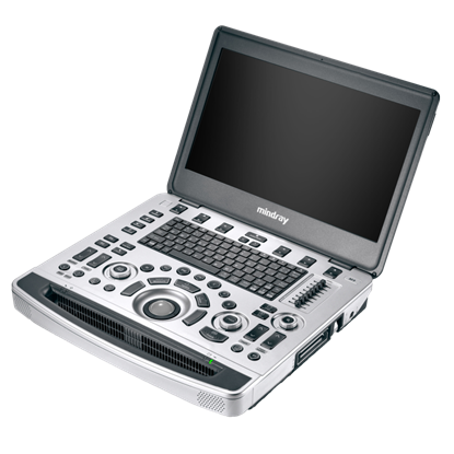
Описание
Данный ультразвуковой аппарат предполагает широкий спектр возможностей, начиная от эластографии, заканчивая возможностью формирования луча с расширенным эхо-сигналом.
Функции Mindray M9
Технология производства ЗТ датчиков на основе монокристаллов
Все датчики, совместимые с УЗ-сканером M9, изготовлены по уникальной технологии 3Т, разработанной компанией Mindray, и позволяют обеспечить более четкую визуализацию. Благодаря дополнительному использованию монокристаллических элементов, M9 отличается более высокой проникающей способностью и улучшенной динамикой цветопередачи, что особенно актуально при сканировании так называемых «труднодоступных участков».
Эластография Natural Touch
Метод эластографии с имитацией естественного касания на основе новейшей запатентованной технологии Mindray делает результаты исследования менее зависимыми от наличия соответствующих навыков у пользователя, тем самым повышая точность исследования в сложных клинических условиях.
Эффективное выявление уплотнений
Стабильно высокая воспроизводимость результатов исследования
Визуализация с применением контрастных веществ UWN+ (нелинейная визуализация в ультрашироком диапазоне)
Самое большое преимущество УЗ-сканера M9 заключается в поддержке запатентованной Mindray технологии, позволяющей расширить возможности визуализации с применением контраста. Технология UWN+ дает возможность M9 обнаруживать и использовать как вторичные гармоники, так и нелинейные первичные сигналы, создавая изображения более высокого качества.
Более высокая чувствительность к второстепенным сигналам, меньший расход действующего вещества
Более длительное время действия активного вещества и более низкие требования к интервалу измерения
PSHI™ (гармоническая визуализация с фазовым сдвигом)
Изолированная гармоническая визуализация для улучшения контрастного разрешения, обеспечивающая более четкое изображение с превосходным пространственным разрешением и меньшим уровнем шума.
Тканевая гармоника
Используя дополнительные гармоники, генерируемые в тканях пограничных слоев, ТГ значительно увеличивает контрастное разрешение и улучшает качество изображения, особенно когда доступ к исследуемому участку затруднен.
ТСВ (тканеспецифическая визуализация)
Тканеспецифическая визуализация оптимизирует качество изображения в зависимости от свойств исследуемой ткани. Доступны четыре варианта настройки изображения: общие, мышечные ткани, жидкие среды и жировая ткань.
iBeam™
Позволяет использовать несколько углов сканирования для формирования единого изображения, что приводит к повышению контрастного разрешения и улучшению визуализации.
iClear™
Позволяет улучшить качество изображения, основываясь на автоматическом распознавании структур.
Более четкие края и контуры
Плавное и однородное отображение тканей
Снижение зернистости в «областях без эхосигнала»
Формирование луча с расширенным эхо-сигналом
Устройство формирования луча с расширенным эхо-сигналом позволяет использовать традиционно игнорируемые эхо-сигналы смежных лучей, формируя один более тонкий и сильный луч изображения, обеспечивающий более высокое разрешение «вне фокуса» изображения и более глубокое проникновение визуализации.
Формирование мульти-луча
Увеличение скорости обработки сигнала от одного луча до 12 раз, что позволяет достигать превосходного разрешения по времени и более высокой частоты кадров.
Расширенная визуализация микропотока
Позволяет лучше визуализировать небольшие перфузии сосудов и лучше оценивать кровоснабжение патологии за счет использования группы кадров для генерирования объединенных изображений.
iScape™
Дает полный и расширенный обзор анатомических структур посредством панорамной визуализации, в сочетании с индикатором скорости и функцией прямого / обратного сканирования, делая процесс более легким, последовательным и управляемым.
ExFOV
В Вашем распоряжении окажется самая полная диагностическая информация благодаря детализированной визуализации анатомических структур на всех конвексных и линейных датчиках.
Трапециевидная визуализация
Большая точность и полнота диагностической информации обеспечиваются благодаря расширенному обзору анатомического строения на всех линейных датчиках.
B-Steer™/ iNeedle™
Ваш инструмент для более глубокой биопсии: обеспечивает маневрирование УЗ-луча, чтобы улучшить видимость иглы, нервных волокон и мелких сосудов.
iStation™
Уникальная система управления информацией о пациенте от компании Mindray позволит Вам эффективно интегрировать, просматривать, архивировать и извлекать данные о пациенте.
Выполнение рабочих операций Mindray M9
iZoom™
Обеспечивает мгновенное переключение в полноэкранный режим нажатием одной клавиши.
Auto IMT (автоматическое определение толщины комплекса интима-медиа)
Автоматическое измерение толщины передней и задней стенки, предоставляющее точную информацию о состоянии сонной артерии.
iStation™
Уникальная система управления информацией о пациенте от компании Mindray позволит Вам эффективно интегрировать, просматривать, архивировать и извлекать данные о пациенте.
iTouch™
Позволяет выполнять мгновенную автоматическую оптимизацию изображения в режимах В, при цветном и импульсно-волновом допплере (PW) нажатием одной клавиши.
iWorks™
Высокотехнологичный инструмент, который дает Вам возможность сосредоточить свое внимание на пациенте. Позволяет значительно сократить время сканирования пациента благодаря стандартизации операций и настраиваемым пользователем функциям.
Работа с «сырыми данными»
Открывает широкие возможности для пост-обработки сохраненных изображений, включая настройку параметров, добавление комментариев и данных измерений, что обеспечивает максимальную продуктивность во время сканирования.
Технические характеристики:
Тонкий корпус из магниевого сплава;
15,6″ светодиодный тонкий монитор HD;
Встроенный аккумулятор обеспечивает время сканирования, равное 90 мин;
SSD жесткий диск повышенной емкости обеспечивает безопасное хранение данных пациента;
Специализированная тележка для установки и перевозки аппарата;
Удобная встроенная система закрепления сканера;
Система iPower: более 3,5 часов сканирования в автономном режиме благодаря дополнительному блоку аккумуляторов;
Полное соответствие экологическим нормам;
Бесшумная работа;
Автоматическая регулировка яркости экрана;
Надежные материалы, имеющие сертификат соответствия RoHS;
Технология датчиков 3Т на основе монокристаллов;
Уникальная адаптивная технология обработки сигнала Echo Boost;
Функция позиционирования тканей с количественным анализом;
ЛВК со стресс-эхокардиографией;
PSHI (гармоническая визуализация с фазовым сдвигом);
Тканевая гармоника (ТГ);
ТСВ (тканеспецифическая визуализация).
Доступные датчики:
Конвексный датчик С5-1s, 1.3 — 5,1 МГц;
Высокоплотный линейный датчик L12-4s, 3,0 — 13,0 МГц;
Высокочастотный высокоплотный линейный датчик L14-6Ns, 3,5 — 16,0 МГц;
Линейный датчик L10-3s, 2,7 — 10,5 МГц;
Высокочастотный высокоплотный линейный датчик L14-6Ws, 3,5 — 16,0 МГц;
Высокочастотный высокоплотный линейный датчик L14-6Ws, 3,5 — 16,0 МГц;
Высокочастотный высокоплотный линейный датчик L20-5s;
Линейный интраоперационный L-образный датчик L16-4Hs, 3,5 — 16 МГц;
Секторный фазированный монокристаллиический датчик ,SP5-1s;
Секторный фазированный педиатрический датчик P7-3s, 2,0 — 8,0 МГц;
Секторный фазированный неонатальный датчик P10-4s;
Микроконвексный внутриполостной датчик V11-3Ws, 3,0 — 11,2 МГц;
Микроконвексный датчик C11-3s, 3,0 -11,2 МГц;
Конвексный датчик С6-2Gs, 1 — 6,0 МГц;
Секторный фазированный чреспищеводный датчик P7-3, 1,9 — 8,2 МГц;
Фазированный карандашный датчик для «слепых» кардиоваскулярных исследований CW2s, 2 МГц;
Фазированный карандашный датчик для «слепых» сосудистых исследований CW5s, 5 МГц;
Конвексный датчик объемного сканирования D7-2s.
Характеристики
Класс аппарата: Экспертный
Вид эластографии: Компрессионная
Виды поддерживаемых датчиков
Конвексный, Микроконвексный, Линейный (до 15 МГц), Линейный низкочастотный (до 10 МГц), Линейный ультравысокочастотный (от 18 МГц), Секторный фазированный взрослый, Секторный фазированный педиатрический, Секторный фазированный неонатальный, Полостной конвексный, Объемный конвексный, Карандашный, Интраоперационный конвексный, Интраоперационный линейный, Чреспищеводный взрослый
Типы поддерживаемых датчиков: Монокристаллический, Высокоплотный, Матричный
Тип устройства: Портативный
Специализация (УЗИ): Кардиология
Поддержка постоянно-волнового доплера (CW)
Поддержка анатомического М-режима
Наличие блока объемного сканирования (4D)
Размер экрана, ″ 15
Аппарат ультразвуковой диагностический серии М с принадлежностями, варианты исполнения: М9, М9Т, М9CV
1. Аппарат ультразвуковой диагностический серии М, варианты исполнения М9 с принадлежностями, в составе: 1.1. Аппарат ультразвуковой диагностический серии М, варианты исполнения М9 основной блок (Main Unit) — 1 шт. 1.2. Кабель питания (Power cord) — 1 шт. 1.3. Встроенная батарея (Built-in battery). 1.4. Адаптер переменного тока в постоянный (АС adapter), не более 2 шт. 1.5. Руководство по эксплуатации в печатном виде (User Manual print), не более 5 шт. 1.6. Руководство по эксплуатации CD (User Manual CD), не более 5 шт. 1.7. Чемодан для транспортировки аппарата (Wheeled Boarding Bag) — 1 шт. 1.8. Датчики ультразвуковые: — конвексный C5-ls (Convex array ultrasound probe: C5-ls), не более 5 шт. (при необходимости). — конвексный C6-2Gs Convex array ultrasound probe: C6-2Gs), не более 5 шт. (при необходимости). — микроконвексный Сl1-3s (Micro-convex array ultrasound probe: Cl1-3s), не более 5 шт. (при необходимости). — линейный: L10-3S (Linear array ultrasound probe: L10-3s), не более 5 шт. (при необходимости). — линейный: L12-4s (Linear array ultrasound probe: L12-4s), не более 5 шт. (при необходимости). — линейный: L14-6Ns (Linear array ultrasound probe: L14-6Ns), не более 5 шт. (при необходимости). — линейный: LM14-6s (Linear array ultrasound probe: LM14-6s), не более 5 шт. (при необходимости). — линейный: L14-6WS (Linear array ultrasound probe: L14-6Ws), не более 5 шт. (при необходимости). — линейный: L20-5s (Linear array ultrasound probe: L20-5s), не более 5 шт. (при необходимости). — интраоперационный L16-4Hs (Intra-operative linear array transducer: L16-4Hs), не более 5 шт. (при необходимости). — внутриполостной V11-3Ws (Endocavity ultrasound probe: V11 -3Ws), не более 5 шт. (при необходимости). — объемный внутриполостной DE11-3s (Endocavity Volume ultra-sound probe: DE11-3s), не более 5 шт. (при необходимости). — объемный D7-2s (Volume ultrasound probe: D7-2s), не более 5 шт. (при необходимости). — трансректальный биплановый СВ10-4s (Electronic bi-plane transducer: CB10-4s) не более 3 шт. (при необходимости). — фазированный SP5-ls (Phased array ultrasound probe: SP5-ls), не более 5 шт. (при необходимости). — фазированный P10-4s (Phased array ultrasound probe: P10-4s), не более 5 шт. (при необходимости). — фазированный P7-3s (Phased array ultrasound probe: P7-3s), не более 5 шт. (при необходимости). — секторный фазированный P7-3TS (Transesophageal ultrasound probe: P7-3Ts), не более 5 шт. (при необходимости). — карандашный CW5s (Pencil probe: CW5s), не более 2 шт. (при необходимости). — карандашный CW2s (Pencil probe: CW2s), не более 2 шт. (при необходимости). 1.9. Модули: — приема ЭКГ сигналов с кабелем ЭКГ (Physio Module (includes ECG with cords), не более 2 шт. (при необходимости). — постоянно-волнового допплера (CW module) (при необходимости). — объемного сканирования в реальном времени (4D module) (при необходимости). — физиологических сигналов (Physiology module) — 1 шт. (при необходимости). — тканевого допплера (TDI) (при необходимости). 1.10. Насадки биопсийные (Biopsy bracket): — NGB-004, не более 5 шт. (при необходимости). — NGB-007, не более 5 шт. (при необходимости). — NGB-022, не более 5 шт. (при необходимости). — NGB-011, не более 5 шт. (при необходимости). — NGB-018, не более 5 шт. (при необходимости). — NGB-023, не более 5 шт. (при необходимости). — NGB-024, не более 5 шт. (при необходимости). 1.11. Программное обеспечение измерений и вычислений: — для абдоминальных исследований. (Abdominal package) (при необходимости). — для акушерства (Obstetrics package) (при необходимости). — для гинекологии (Gynecology package) (при необходимости). — для урологии (Urology package) (при необходимости). — для педиатрии (Pediatric package) (при необходимости). — вычислений для кардиологии (Cardio package) (при необходимости). — для ангиологии (Angio package) (при необходимости). — для исследования малых органов (Small Organs package) (при необходимости). — для ургентной медицины (Emergency medicine package) (при необходимости). — для регионарной анестезии (Nerve package) (при необходимости). — для всех видов исследований (абдоминальных, акушерских, гинекологических, урологических, педиатрических, кардиологических, ангиологических, малых органов, ургентной медицины, регионарной анестезии) (Shared service package) (при необходимости). 1.12. Программное обеспечение: — для интеграции в больничную сеть DICOM, не более 8 шт. (при необходимости). — для панорамного сканирования (iScape) (при необходимости). — анатомического М-режима (Free Xros М) (при необходимости). — для криволинейного анатомического М-режима (Free Xros CM) (при необходимости). — для автоматического измерения комплекса интима-медиа (IMT) (при необходимости). — для количественного анализа в режиме тканевого допплера (TDIQA) (при необходимости). — для исследований (Measure and Calculation Software Packages) (при необходимости). — для эластографин с программой анализа (Elastography) (при необходимости). — автоматизированных рабочих протоколов iWorks (Standardized Workflow Protocol) (при необходимости). — для улучшения визуализации биопсийной иглы (iNeedle) (при необходимости). — для оценки результатов стресс-эхокардиографии (Stress Echo) (при необходимости). — для недопплеровской количественной оценки движения и деформации миокарда (Tissue Tracking with Quantivative Analysis) (при необходимости). — для абдоминальных исследований с контрастированием (UWN+ Contrast) (при необходимости). — для количественной оценки в режиме абдоминальных исследований с контрастированием (UWN+ Contrast QA) (при необходимости). — для исследований ЛЖ с контрастированием (LVO Contrast) (при необходимости). — для автоматического измерения акушерско-гинекологических параметров Smart OB (Automatic obstetrical measurements) (при необходимости). — для автоматического измерения воротникового пространства у плода Smart NT (Automatic calculation of Nuchal Translucency) (при необходимости). — для построения 3D изображений при помощи 2D датчиков Smart 3D (Freehand 3D) (при необходимости). — для построения объемного изображения с применением технологии виртуальной подсветки плода iLive (Rendering mode for realistic volume imaging display) (при необходимости). — для мультисрезового томографического отображения с регулировкой толщины среза (iPage+) (при необходимости). — для получения произвольного среза заданной толщины в объемном изображении с одновременным улучшением контрастности SCV + (Slice Contrast View Plus) (при необходимости). — для исследования объемного изображения сердца плода STIC (Spatio-Temporal Imaging Correlation) (при необходимости). — для трехмерного изображения в режиме цветового/энергетического допплеровского картирования Color 3D (3D supports color and power mode) (при необходимости). — для произвольного выбора среза в объемном изображении с одновременным отображением трех плоскостей Niche/3Slice (3 slice view) (при необходимости). — для автоматического расчета объема и размеров структур в объемном изображении Smart-V (Automatic calculation of the volume and measurements in 3D-4D) (при необходимости). — для автоматического оконтуривания, подсчета и определения размеров фолликулов Smart FLC (Smart Follicle) (при необходимости). — для голосового управления (Voice Recognition) (при необходимости).
2. Аппарат ультразвуковой диагностический серии М, варианты исполнения М9 с принадлежностями, в составе: 2.1. Аппарат ультразвуковой диагностический серии М, варианты исполнения М9 основной блок (Main Unit) — 1 шт. 2.2. Кабель питания (Power cord) — 1 шт. 2.3. Встроенная батарея (Built-in battery). 2.4. Адаптер переменного тока в постоянный (АС adapter), не более 2 шт. 2.5. Руководство по эксплуатации в печатном виде (User Manual print), не более 5 шт. 2.6. Руководство по эксплуатации CD (User Manual CD), не более 5 шт. 2.7. Чемодан для транспортировки аппарата (Wheeled Boarding Bag) — 1 шт. 2.8. Датчик ультразвуковой конвексный C5-ls (Convex array ultrasound probe: C5-ls), не более 5 шт. (при необходимости).
3. Аппарат ультразвуковой диагностический серии М, варианты исполнения М9Т с принадлежностями, в составе: 3.1. Аппарат ультразвуковой диагностический серии М, варианты исполнения М9Т основной блок (Main Unit) — 1 шт. 3.2. Кабель питания (Power cord) — 1 шт. 3.3. Встроенная батарея (Built-in battery). 3.4. Адаптер переменного тока в постоянный (АС adapter), не более 2 шт. 3.5. Руководство по эксплуатации в печатном виде (User Manual print), не более 5 шт. 3.6. Руководство по эксплуатации CD (User Manual CD), не более 5 шт. 3.7. Чемодан для транспортировки аппарата (Wheeled Boarding Bag) — 1 шт. 3.8. Датчики ультразвуковые: — конвексный C5-ls (Convex array ultrasound probe: C5-ls), не более 5 шт. (при необходимости). — конвексный C6-2Gs Convex array ultrasound probe: C6-2Gs), не более 5 шт. (при необходимости). — микроконвексный Сl1-3s (Micro-convex array ultrasound probe:Cl1-3s), не более 5 шт. (при необходимости). — линейный: L10-3S (Linear array ultrasound probe: L10-3s), не более 5 шт. (при необходимости). — линейный: L12-4s (Linear array ultrasound probe: L12-4s), не более 5 шт. (при необходимости). — линейный: L14-6Ns (Linear array ultrasound probe: L14-6Ns), не более 5 шт. (при необходимости). — линейный: LM14-6s (Linear array ultrasound probe: LM14-6s), не более 5 шт. (при необходимости). — линейный: L14-6WS (Linear array ultrasound probe: L14-6Ws), не более 5 шт. (при необходимости). — линейный: L20-5s (Linear array ultrasound probe: L20-5s), не более 5 шт. (при необходимости). — интраоперационный L16-4Hs (Intra-operative linear array transducer: L16-4Hs), не более 5 шт. (при необходимости). — внутриполостной V11-3Ws (Endocavity ultrasound probe: V11 -3Ws), не более 5 шт. (при необходимости). — объемный внутриполостной DE11-3s (Endocavity Volume ultra-sound probe: DE11-3s), не более 5 шт. (при необходимости). — объемный D7-2s (Volume ultrasound probe: D7-2s), не более 5 шт. (при необходимости). — трансректальный биплановый СВ10-4s (Electronic bi-plane transducer: CB10-4s) не более 3 шт. (при необходимости). — фазированный SP5-ls (Phased array ultrasound probe: SP5-ls), не более 5 шт. (при необходимости). — фазированный P10-4s (Phased array ultrasound probe: P10-4s), не более 5 шт. (при необходимости). — фазированный P7-3s (Phased array ultrasound probe: P7-3s), не более 5 шт. (при необходимости). — секторный фазированный P7-3TS (Transesophageal ultrasound probe: P7-3Ts), не более 5 шт. (при необходимости). — карандашный CW5s (Pencil probe: CW5s), не более 2 шт. (при необходимости). — карандашный CW2s (Pencil probe: CW2s), не более 2 шт. (при необходимости). 3.9. Модули: — приема ЭКГ сигналов с кабелем ЭКГ (Physio Module (includes ECG with cords), не более 2 шт. (при необходимости). — постоянно-волнового допплера (CW module) (при необходимости). — объемного сканирования в реальном времени (4D module) (при необходимости). — физиологических сигналов (Physiology module) — 1 шт. (при необходимости). — тканевого допплера (TDI) (при необходимости). 3.10. Насадки биопсийные (Biopsy bracket): — NGB-004, не более 5 шт. (при необходимости). — NGB-007, не более 5 шт. (при необходимости). — NGB-022, не более 5 шт. (при необходимости). — NGB-011, не более 5 шт. (при необходимости). — NGB-018, не более 5 шт. (при необходимости). — NGB-023, не более 5 шт. (при необходимости). — NGB-024, не более 5 шт. (при необходимости). 3.11. Программное обеспечение измерений и вычислений: — для абдоминальных исследований. (Abdominal package) (при необходимости). — для акушерства (Obstetrics package) (при необходимости). — для гинекологии (Gynecology package) (при необходимости). — для урологии (Urology package) (при необходимости). — для педиатрии (Pediatric package) (при необходимости). — вычислений для кардиологии (Cardio package) (при необходимости). — для ангиологии (Angio package) (при необходимости). — для исследования малых органов (Small Organs package) (при необходимости). — для ургентной медицины (Emergency medicine package) (при необходимости). — для регионарной анестезии (Nerve package) (при необходимости). — для всех видов исследований (абдоминальных, акушерских, гинекологических, урологических, педиатрических, кардиологических, ангиологических, малых органов, ургентной медицины, регионарной анестезии) (Shared service package) (при необходимости). 3.12. Программное обеспечение: — для интеграции в больничную сеть DICOM, не более 8 шт. (при необходимости). — для панорамного сканирования (iScape) (при необходимости). — анатомического М-режима (Free Xros М) (при необходимости). — для криволинейного анатомического М-режима (Free Xros CM) (при необходимости). — для автоматического измерения комплекса интима-медиа (IMT) (при необходимости). — для количественного анализа в режиме тканевого допплера (TDIQA) (при необходимости). — для исследований (Measure and Calculation Software Packages) (при необходимости). — для эластографин с программой анализа (Elastography) (при необходимости). — автоматизированных рабочих протоколов iWorks (Standardized Workflow Protocol) (при необходимости). — для улучшения визуализации биопсийной иглы (iNeedle) (при необходимости). — для оценки результатов стресс-эхокардиографии (Stress Echo) (при необходимости). — для недопплеровской количественной оценки движения и деформации миокарда (Tissue Tracking with Quantivative Analysis) (при необходимости). — для абдоминальных исследований с контрастированием (UWN+ Contrast) (при необходимости). — для количественной оценки в режиме абдоминальных исследований с контрастированием (UWN+ Contrast QA) (при необходимости). — для исследований ЛЖ с контрастированием (LVO Contrast) (при необходимости). — для автоматического измерения акушерско-гинекологических параметров Smart ОВ (Automatic obstetrical measurements) (при необходимости). — для автоматического измерения воротникового пространства у плода Smart NT (Automatic calculation of Nuchal Translucency) (при необходимости). — для построения 3D изображений при помощи 2D датчиков Smart 3D (Freehand 3D) (при необходимости). — для построения объемного изображения с применением технологии виртуальной подсветки плода iLive (Rendering mode for realistic volume imaging display) (при необходимости). — для мультисрезового томографического отображения с регулировкой толщины среза (iPage+) (при необходимости). — для получения произвольного среза заданной толщины в объемном изображении с одновременным улучшением контрастности SCV + (Slice Contrast View Plus) (при необходимости). — для исследования объемного изображения сердца плода STIC (Spatio-Temporal Imaging Correlation) (при необходимости). — для трехмерного изображения в режиме цветового/энергетического допплеровского картирования Color 3D (3D supports color and power mode) (при необходимости). — для произвольного выбора среза в объемном изображении с одновременным отображением трех плоскостей Niche/3Slice (3 slice view) (при необходимости). — для автоматического расчета объема и размеров структур в объемном изображении Smart-V (Automatic calculation of the volume and measurements in 3D- 4D) (при необходимости). — для автоматического оконтуривания, подсчета и определения размеров фолликулов Smart FLC (Smart Follicle) (при необходимости). — для голосового управления (Voice Recognition) (при необходимости).
4. Аппарат ультразвуковой диагностический серии М, варианты исполнения М9Т с принадлежностями, в составе: 4.1. Аппарат ультразвуковой диагностический серии М, варианты исполнения М9Т основной блок (Main Unit) — 1 шт. 4.2. Кабель питания (Power cord) — 1 шт. 4.3. Встроенная батарея (Built-in battery). 4.4. Адаптер переменного тока в постоянный (АС adapter), не более 2 шт. 4.5. Руководство по эксплуатации в печатном виде (User Manual print), не более 5 шт. 4.6. Руководство по эксплуатации CD (User Manual CD), не более 5 шт. 4.7. Чемодан для транспортировки аппарата (Wheeled Boarding Bag) — 1 шт. 4.8. Датчик ультразвуковой конвексный C5-ls (Convex array ultrasound probe: C5-ls), не более 5 шт. (при необходимости).
5. Аппарат ультразвуковой диагностический серии М, варианты исполнения M9CV с принадлежностями, в составе: 5.1. Аппарат ультразвуковой диагностический серии М, варианты исполнения M9CV основной блок (Main Unit) — 1 шт. 5.2. Кабель питания (Power cord) — 1 шт. 5.3. Встроенная батарея (Built-in battery). 5.4. Адаптер переменного тока в постоянный (АС adapter), не более 2 шт. 5.5. Руководство по эксплуатации в печатном виде (User Manual print), не более 5 шт. 5.6. Руководство по эксплуатации CD (User Manual CD), не более 5 шт. 5.7. Чемодан для транспортировки аппарата (Wheeled Boarding Bag) — 1 шт. 5.8. Датчики ультразвуковые: — конвексный C5-ls (Convex array ultrasound probe: C5-ls), не более 5 шт. (при необходимости). — конвексный C6-2Gs Convex array ultrasound probe: C6-2Gs), не более 5 шт. (при необходимости). — микроконвексный Сl1-3s (Micro-convex array ultrasound probe: Cl1-3s), не более 5 шт. (при необходимости). — линейный: L10-3S (Linear array ultrasound probe: L10-3s), не более 5 шт. (при необходимости). — линейный: L12-4s (Linear array ultrasound probe: L12-4s), не более 5 шт. (при необходимости). — линейный: L14-6Ns (Linear array ultrasound probe: L14-6Ns), не более 5 шт. (при необходимости). — линейный: LM14-6s (Linear array ultrasound probe: LM14-6s), не более 5 шт. (при необходимости). — линейный: L14-6WS (Linear array ultrasound probe: L14-6Ws), не более 5 шт. (при необходимости). — линейный: L20-5s (Linear array ultrasound probe: L20-5s), не более 5 шт. (при необходимости). — интраоперационный L16-4Hs (Intra-operative linear array transducer: L16-4Hs), не более 5 шт. (при необходимости). — внутриполостной V11-3Ws (Endocavity ultrasound probe: V11 -3Ws), не более 5 шт. (при необходимости). — объемный внутриполостной DE11-3s (Endocavity Volume ultra-sound probe: DE11-3s), не более 5 шт. (при необходимости). — объемный D7-2s (Volume ultrasound probe: D7-2s), не более 5 шт. (при необходимости). — трансректальный биплановый СВ10-4s (Electronic bi-plane transducer: CB10-4s) не более 3 шт. (при необходимости). — фазированный SP5-ls (Phased array ultrasound probe: SP5-ls), не более 5 шт. (при необходимости). — фазированный P10-4s (Phased array ultrasound probe: P10-4s), не более 5 шт. (при необходимости). — фазированный P7-3s (Phased array ultrasound probe: P7-3s), не более 5 шт. (при необходимости). — секторный фазированный P7-3TS (Transesophageal ultrasound probe: P7-3Ts), не более 5 шт. (при необходимости). — карандашный CW5s (Pencil probe: CW5s), не более 2 шт. (при необходимости). — карандашный CW2s (Pencil probe: CW2s), не более 2 шт. (при необходимости). 5.9. Модули: — приема ЭКГ сигналов с кабелем ЭКГ (Physio Module (includes ECG with cords), не более 2 шт. (при необходимости). — постоянно-волнового допплера (CW module) (при необходимости). — объемного сканирования в реальном времени (4D module) (при необходимости). — физиологических сигналов (Physiology module) — 1 шт. (при необходимости). — тканевого допплера (TDI) (при необходимости). 5.10. Насадки биопсийные (Biopsy bracket): — NGB-004, не более 5 шт. (при необходимости). — NGB-007, не более 5 шт. (при необходимости). — NGB-022, не более 5 шт. (при необходимости). — NGB-011, не более 5 шт. (при необходимости). — NGB-018, не более 5 шт. (при необходимости). — NGB-023, не более 5 шт. (при необходимости). — NGB-024, не более 5 шт. (при необходимости). 5.11. Программное обеспечение измерений и вычислений: — для абдоминальных исследований. (Abdominal package) (при необходимости). — для акушерства (Obstetrics package) (при необходимости). — для гинекологии (Gynecology package) (при необходимости). — для урологии (Urology package) (при необходимости). — для педиатрии (Pediatric package) (при необходимости). — вычислений для кардиологии (Cardio package) (при необходимости). — для ангиологии (Angio package) (при необходимости). — для исследования малых органов (Small Organs package) (при необходимости). — для ургентной медицины (Emergency medicine package) (при необходимости). — для регионарной анестезии (Nerve package) (при необходимости). — для всех видов исследований (абдоминальных, акушерских, гинекологических, урологических, педиатрических, кардиологических, ангиологических, малых органов, ургентной медицины, регионарной анестезии) (Shared service package) (при необходимости). 5.12. Программное обеспечение: — для интеграции в больничную сеть DICOM, не более 8 шт. (при необходимости). — для панорамного сканирования (iScape) (при необходимости). — анатомического М-режима (Free Xros М) (при необходимости). — для криволинейного анатомического М-режима (Free Xros CM) (при необходимости). — для автоматического измерения комплекса интима-медиа (IMT) (при необходимости). — для количественного анализа в режиме тканевого допплера (TDIQA) (при необходимости). — для исследований (Measure and Calculation Software Packages) (при необходимости). — для эластографин с программой анализа (Elastography) (при необходимости). — автоматизированных рабочих протоколов iWorks (Standardized Workflow Protocol) (при необходимости). — для улучшения визуализации биопсийной иглы (iNeedle) (при необходимости). — для оценки результатов стресс-эхокардиографии (Stress Echo) (при необходимости). — для недопплеровской количественной оценки движения и деформации миокарда (Tissue Tracking with Quantivative Analysis) (при необходимости). — для абдоминальных исследований с контрастированием (UWN+ Contrast) (при необходимости). — для количественной оценки в режиме абдоминальных исследований с контрастированием (UWN+ Contrast QA) (при необходимости). — для исследований ЛЖ с контрастированием (LVO Contrast) (при необходимости). — для автоматического измерения акушерско-гинекологических параметров Smart ОВ (Automatic obstetrical measurements) (при необходимости). — для автоматического измерения воротникового пространства у плода Smart NT (Automatic calculation of Nuchal Translucency) (при необходимости). — для построения 3D изображений при помощи 2D датчиков Smart 3D (Freehand 3D) (при необходимости). — для построения объемного изображения с применением технологии виртуальной подсветки плода iLive (Rendering mode for realistic volume imaging display) (при необходимости). — для мультисрезового томографического отображения с регулировкой толщины среза (iPage+) (при необходимости). — для получения произвольного среза заданной толщины в объемном изображении с одновременным улучшением контрастности SCV + (Slice Contrast View Plus) (при необходимости). — для исследования объемного изображения сердца плода STIC (Spatio-Temporal Imaging Correlation) (при необходимости). — для трехмерного изображения в режиме цветового/энергетического допплеровского картирования Color 3D (3D supports color and power mode) (при необходимости). — для произвольного выбора среза в объемном изображении с одновременным отображением трех плоскостей Niche/3Slice (3 slice view) (при необходимости). — для автоматического расчета объема и размеров структур в объемном изображении Smart-V (Automatic calculation of the volume and measurements in 3D-4D) (при необходимости). — для автоматического оконтуривания, подсчета и определения размеров фолликулов Smart FLC (Smart Follicle) (при необходимости). — для голосового управления (Voice Recognition) (при необходимости).
6. Аппарат ультразвуковой диагностический серии М, варианты исполнения M9CV с принадлежностями, в составе: 6.1. Аппарат ультразвуковой диагностический серии М, варианты исполнения M9CV основной блок (Main Unit) — 1 шт. 6.2. Кабель питания (Power cord) — 1 шт. 6.3. Встроенная батарея (Built-in battery). 6.4. Адаптер переменного тока в постоянный (АС adapter), не более 2 шт. 6.5. Руководство по эксплуатации в печатном виде (User Manual print), не более 5 шт. 6.6. Руководство по эксплуатации CD (User Manual CD), не более 5 шт. 6.7. Чемодан для транспортировки аппарата (Wheeled Boarding Bag) — 1 шт. 6.8. Датчик ультразвуковой конвексный C5-ls (Convex array ultrasound probe: C5-ls), не более 5 шт. (при необходимости).
Принадлежности: 1. Дополнительный кабель питания (power cord) — не более 2 шт. 2. Тележка передвижная (Mobile trolley), типы: UМТ-500 (Mobile Trolley UMT-500) — 1 шт. UMT-500Plus (Mobile Trolley UMT-500Plus) — 1 шт. 3. Разветвитель на три порта для датчиков (Transducer extension module for triple transducer connection, PEM-51) — 1 шт. 4. Док-станция с набором портов для подключения внешних устройств (IOM-51, iDock) — 1 шт. 5. Дополнительная батарея (Rechargeable battery), не более 2 шт. 6. Чехол для клавиатуры (Keyboard Cover), не более 5 шт. 7. Внешнее записывающее DVD-устройство (DVD-RW) — 1 шт. 8. Чехол для сканера (Dust-proof cover for Main Unit), не более 3 шт. 9. Наклейка на панель мультиязычная (Multilanguage control overlay), не более 5 шт. 10. Кабель заземления (Grounding cable), не более 2 шт. 11. Сумка для переноски (Hand carried bag), не более 2 шт. 12. Ножной переключатель, две педали (Footswitch, 2 keys) — 1 шт. 13. Ножной переключатель, три педали (Footswitch, 3 keys) — 1 шт. 14. Переходник с USB на LAN (USB to network converter) — 1 шт. 15. Кабель питания для тележки передвижной (Power cable for mobile trolley), не более 2 шт.