-
Contents
-
Table of Contents
-
Troubleshooting
-
Bookmarks
Quick Links
TRANSISTORIZED INVERTER
FR-E
500
INSTRUCTION MANUAL
HIGH PERFORMANCE
HIGH FUNCTION
FR-E520-0.1K to 7.5K-NA
FR-E540-0.4K to 7.5K-NA
FR-E510W-0.1K to 0.75K-NA
&
OUTLINE
INSTALLATION
AND WIRING
OPERATION/
CONTROL
PARAMETERS
PROTECTIVE
FUNCTIONS
SPECIFICATIONS
Chapter 1
Chapter 2
Chapter 3
Chapter 4
Chapter 5
Chapter 6
Related Manuals for Mitsubishi Electric FR-E500
Summary of Contents for Mitsubishi Electric FR-E500
-
Page 1: Instruction Manual
TRANSISTORIZED INVERTER FR-E INSTRUCTION MANUAL HIGH PERFORMANCE & HIGH FUNCTION FR-E520-0.1K to 7.5K-NA FR-E540-0.4K to 7.5K-NA OUTLINE Chapter 1 FR-E510W-0.1K to 0.75K-NA INSTALLATION Chapter 2 AND WIRING OPERATION/ Chapter 3 CONTROL Chapter 4 PARAMETERS PROTECTIVE Chapter 5 FUNCTIONS SPECIFICATIONS Chapter 6…
-
Page 2
Thank you for choosing the Mitsubishi Transistorized inverter. This instruction manual gives handling information and precautions for use of this equipment. Incorrect handling might cause an unexpected fault. Before using the inverter, please read this manual carefully to use the equipment to its optimum. Please forward this manual to the end user. -
Page 3: Safety Instructions
SAFETY INSTRUCTIONS 1. Electric Shock Prevention WARNING While power is on or when the inverter is running, do not open the front cover. You may get an electric shock. Do not run the inverter with the front cover removed. Otherwise, you may access the exposed high-voltage terminals or the charging part of the circuitry and get an electric shock.
-
Page 4
3. Injury Prevention CAUTION Apply only the voltage specified in the instruction manual to each terminal to prevent damage etc. Ensure that the cables are connected to the correct terminals. Otherwise, damage etc. may occur. Always make sure that polarity is correct to prevent damage etc. While power is on and for some time after power-off, do not touch the inverter or brake resistor as they are hot and you may get burnt. -
Page 5
( 2 ) Wiring CAUTION Do not fit capacitive equipment such as a power factor correction capacitor, radio noise filter or surge suppressor to the output of the inverter. The connection orientation of the output cables U, V, W to the motor will affect the direction of rotation of the motor. -
Page 6
CAUTION When a 400V class motor is inverter-driven, it should be insulation-enhanced or surge voltages suppressed. Surge voltages attributale to the wiring constants may occur at the motor terminals, deteriorating the insulation of the motor. When parameter clear or all clear is performed, each parameter returns to the factory setting. -
Page 7: Table Of Contents
CONTENTS 1 OUTLINE 1.1 Pre-Operation Information………………1 1.1.1 Precautions for operation………………1 1.2 Basic Configuration ………………..3 1.2.1 Basic configuration ………………..3 1.3 Structure……………………4 1.3.1 Appearance and structure ………………. 4 1.3.2 Removal and reinstallation of the front cover …………5 1.3.3 Removal and reinstallation of the wiring cover …………
-
Page 8
3 OPERATION/CONTROL 3.1 Pre-Operation Information………………49 3.1.1 Types of operation modes …………….. 49 3.1.2 Power on………………….51 3.2 About the Control Panel ………………. 52 3.2.1 Names and functions of the control panel (FR-PA02- )……..52 3.2.2 Control panel mode is changed by pressing the key …….. -
Page 9
4.2.8 Starting frequency (Pr. 13)…………….. 81 4.2.9 Load pattern selection (Pr. 14) …………….82 4.2.10 Jog operation (Pr. 15, Pr. 16) …………….83 4.2.11 Stall prevention (Pr. 22, Pr. 23, Pr. 66) …………84 4.2.12 Acceleration/deceleration pattern (Pr. 29) …………86 4.2.13 Regenerative brake duty (Pr. -
Page 10
4.2.41 User group selection (Pr. 160, Pr. 173 to Pr. 176)……… 143 4.2.42 Actual operation hour meter clear (Pr. 171)……….. 145 4.2.43 Input terminal function selection (Pr. 180 to Pr. 183)……..145 4.2.44 Output terminal function selection (Pr. 190 to Pr. 192)……..147 4.2.45 Cooling fan operation selection (Pr. -
Page 11
5.3.3 Periodic inspection………………. 175 5.3.4 Insulation resistance test using megger…………176 5.3.5 Pressure test………………..176 5.3.6 Daily and Periodic Inspection …………….177 5.3.7 Replacement of parts………………180 5.3.8 Measurement of main circuit voltages, currents and powers……185 6 SPECIFICATIONS 6.1 Standard Specifications ………………188 6.1.1 Model specifications ……………… -
Page 12
Chapter 1 1.2 Basic Configuration…………. 3 1.3 Structure …………..4 Chapter 2 <Abbreviations> y PU Control panel and parameter Chapter 3 unit (FR-PU04) y Inverter Mitsubishi transistorized inverter FR-E500 series y Pr. Chapter 4 Parameter number Chapter 5 Chapter 6… -
Page 13: Outline
1.1 Pre-Operation Information 1.1.1 Precautions for operation This manual is written for the FR-E500 series transistorized inverters. Incorrect handling may cause the inverter to operate incorrectly, causing its life to be reduced considerably, or at the worst, the inverter to be damaged. Handle the inverter properly in accordance with the information in each section as well as the precautions and instructions of this manual to use it correctly.
-
Page 14
OUTLINE ( 2 ) Preparation of instruments and parts required for operation Instruments and parts to be prepared depend on how the inverter is operated. Prepare equipment and parts as necessary. (Refer to page 49.) ( 3 ) Installation To operate the inverter with high performance for a long time, install the inverter in a proper place, in the correct direction, with proper clearances. -
Page 15: Basic Configuration
1.2 Basic Configuration OUTLINE 1.2 Basic Configuration 1.2.1 Basic configuration The following devices are required to operate the inverter. Proper peripheral devices must be selected and correct connections made to ensure proper operation. Incorrect system configuration and connections can cause the inverter to operate improperly, its life to be reduced considerably, and in the worst case, the inverter to be damaged.
-
Page 16: Structure
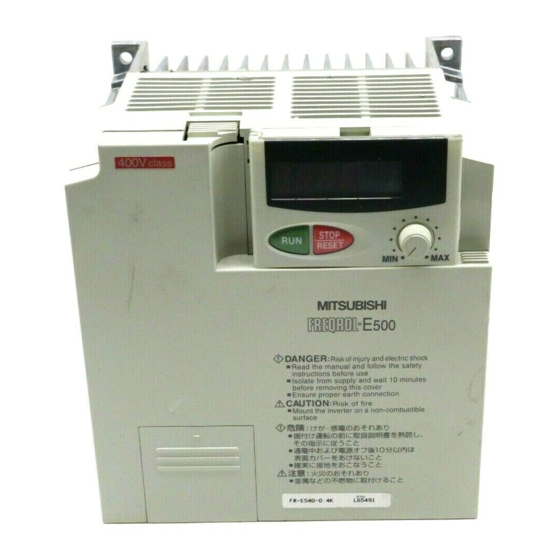
1.3 Structure OUTLINE 1.3 Structure 1.3.1 Appearance and structure (1) Front view (400V class) (100V class, 200V class) POWER lamp (yellow) Accessory cover ALARM lamp (red) Capacity plate Rating plate Front cover Wiring port cover for option (2) Without accessory cover and front cover (100V class, 200V class) (400V class) Inboard option…
-
Page 17: Removal And Reinstallation Of The
OUTLINE 1.3.2 Removal and reinstallation of the front cover z Removal (For the FR-E520-0.1K to 3.7K-NA, FR-E510W-0.1K to 0.75K-NA) The front cover is secured by catches in positions A and B as shown below. Push either A or B in the direction of arrows, and using the other end as a support, pull the front cover toward you to remove.
-
Page 18
OUTLINE (For the FR-E540-0.4K to 7.5K-NA) The front cover is fixed with catches in positions A, B and C. Push A and B in the directions of arrows at the same time and remove the cover using C as supporting points. z Reinstallation When reinstalling the front cover after wiring, fix the catches securely. -
Page 19: Removal And Reinstallation Of The Wiring Cover
OUTLINE 1.3.3 Removal and reinstallation of the wiring cover z Removal (For the FR-E520-0.1K to 7.5K-NA, FR-E510W-0.1K to 0.75K-NA) The wiring cover is fixed by catches in positions 1) and 2). Push either 1) or 2) in the direction of arrows and pull the wiring cover downward to remove.
-
Page 20: Removal And Reinstallation Of The Accessory Cover
OUTLINE 1.3.4 Removal and reinstallation of the accessory cover z Removal of the accessory cover Hold down the portion A indicated by the arrow and lift the right hand side using the portion B indicated by the arrow as a support, and pull out the accessory cover to the right.
-
Page 21: Reinstallation And Removal Of The Control Panel
OUTLINE 1.3.5 Reinstallation and removal of the control panel To ensure safety, reinstall and removal the optional control panel (FR-PA02- ) after switching power off. The charging area and control printed board are exposed on the rear surface of the control panel.
-
Page 22: Removal Of The Control Panel (Fr-Pa02- )
OUTLINE z Using the connection cable for operation 1) Fit the rear cover option FR-E5P to the back surface of the optional control panel. 2) Securely plug one end of the connection cable into the PU connector of the inverter and the other end into the adaptor of the FR-E5P option to connect it to the control panel.
-
Page 23: Exploded View
OUTLINE 1.3.7 Exploded view z FR-E520-0.1K to 7.5K-NA z FR-E510W-0.1K to 0.75K-NA Control panel (FR-PA02 Accessory cover Wiring cover Front cover z FR-E540-0.4K to 7.5K-NA Control panel (FR-PA02- Accessory Front cover cover Wiring port cover for option Wiring cover…
-
Page 24
C H A P T E R 2 CHAPTER 2 INSTALLATION AND INSTALLATIONAND WIRINNG WIRING This chapter gives information on the basic «installation and wiring» for use of this product. Always read the instructions in this chapter before using the equipment. -
Page 25: Installation And Wiring
2.1 Installation INSTALLATION AND WIRING 2 INSTALLATION AND WIRING 2.1 Installation 2.1.1 Instructions for installation For the FR-E520-0.1K to 0.75K-NA and FR-E510W-0.1K to 0.4K-NA, install the inverter with the accessory cover or control panel (FR-PA02- ) front cover open. <For the accessory cover> <For the control panel (FR-PA02 )>…
-
Page 26
10cm (3.94inch) temperatures Leave sufficient or more Cooling air clearances above Measurement and under the position inverter to ensure adequate ventilation. FR-E500 Cooling fan (1.97inch) 1cm (0.39inch) 1cm (0.39inch) (1.97inch) FR-E500 built in the or more* or more* Measurement position inverter (1.97inch) -
Page 27: Wiring
2.2 Wiring INSTALLATION AND WIRING 2.2 Wiring 2.2.1 Terminal connection diagram z 3-phase 200V power input z 3-phase 400V power input Motor 3-phase AC power supply Ground 24VDC power output and external transistor common Jumper Note 5 Remove this jumper when (+)P using the optional power-factor improving DC reactor.
-
Page 28
INSTALLATION AND WIRING z Single-phase 100V power input Motor R (L Power supply S (L Ground Note: 1. To ensure safety, connect the power input to the inverter via a magnetic contactor and earth leakage circuit breaker or no-fuse breaker, and use the magnetic contactor to switch power on-off. -
Page 29
INSTALLATION AND WIRING ( 2 ) Description of the control circuit terminals Terminal Type Symbol Description Name When the STF Forward Turn on the STF signal to start forward and STR signals rotation start rotation and turn it off to stop. are turned on simultaneously, the stop… -
Page 30
INSTALLATION AND WIRING Terminal Type Symbol Description Name Contact output indicating that the output has been stopped by the inverter protective function activated. 230VAC 0.3A, 30VDC A, B, C Alarm output 0.3A. Alarm: discontinuity across B-C (continuity across A-C), normal: continuity Output across B-C (discontinuity across A-C). -
Page 31: Wiring Of The Main Circuit
INSTALLATION AND WIRING 2.2.2 Wiring of the main circuit ( 1 ) Wiring instructions 1) It is recommended to use insulation-sleeved solderless terminals for power supply and motor wiring. 2) Power must not be applied to the output terminals (U, V, W) of the inverter. Otherwise the inverter will be damaged.
-
Page 32
INSTALLATION AND WIRING Overall wiring length (3.7K or more) 500m (1640.40 feet) maximum 300m (984.24 feet) 300m (984.24 feet) 300m (984.24 feet)+300m (984.24 feet)=600m (1968.48 feet) 6) Connect only the recommended optional brake resistor between the terminals P — PR (+ — PR). -
Page 33
INSTALLATION AND WIRING Notes on Grounding z Leakage currents flow in the inverter. To prevent an electric shock, the inverter and motor must be grounded. z Use the dedicated ground terminal to ground the inverter. (Do not use the screw in the case, chassis, etc.) For the earth connection avoid direct contact between aluminium and copper. -
Page 34
INSTALLATION AND WIRING ( 2 ) Terminal block layout FR-E520-0.1K-NA, 0.2K-NA, 0.4K-NA, FR-E520-1.5K-NA, 2.2K-NA, 3.7K-NA 0.75K-NA N/- P/+ P/+ PR Screw size (M4) Screw size (M4) Screw size (M3.5) Screw size (M4) Screw size (M3.5) FR-E520-5.5K-NA, 7.5K-NA Screw size (M5) Screw size (M5) FR-E540-0.4K to 7.5K-NA P/+ PR… -
Page 35
INSTALLATION AND WIRING ( 3 ) Cables, crimping terminals, etc. The following table lists the cables and crimping terminals used with the inputs (R (L S (L ), T (L )) and outputs (U, V, W) of the inverter and the torques for tightening the screws: 1) FR-E520-0.1K-NA to 7.5K-NA PVC insulated… -
Page 36: Wiring Of The Control Circuit
INSTALLATION AND WIRING ( 4 ) Connection of the power supply and motor z Three-phase power input Three-phase power supply 200V Three-phase power supply 400V Motor Ground Ground terminal No-fuse breaker Ground The power supply cables must be connected Connect the motor to U, V, W. In the above to R, S, T (L , L , L ).
-
Page 37
INSTALLATION AND WIRING ( 2 ) Terminal block layout In the control circuit of the inverter, the terminals are arranged as shown below: Terminal screw size: M2.5 (200V class, 100V class) Terminal layout of control circuit (400V class) *AM for the 400V class inverter. ( 3 ) Wiring method 1) For wiring the control circuit, use cables after stripping their sheaths. -
Page 38
INSTALLATION AND WIRING 1) Use tweezers etc. to remove the connector in the sink logic position and fit it in the source logic position. Do this position changing before switching power on. Note: 1. Make sure that the front cover has been installed securely. 2. -
Page 39
INSTALLATION AND WIRING • When using an external power supply for transistor output, use terminal PC as a common to prevent misoperation caused by leakage current. (Do not connect terminal SD of the inverter with terminal 0V of the external power supply. -
Page 40
INSTALLATION AND WIRING • When using an external power supply for transistor output, use terminal SD as a common to prevent misoperation caused by leakage current. Inverter AY-80 DC24V (SD) (5) How to use the STOP signal The following connection example shows how to self-hold the start signals (forward rotation, reverse rotation). -
Page 41: Connection To The Pu Connector
INSTALLATION AND WIRING 2.2.4 Connection to the PU connector ( 1 ) When connecting the control panel or parameter unit using a cable Use the option FR-CB2… or the following connector and commercially available cable: <Connection cable> y Connector : RJ45 connector Example: 5-554720-3, Nippon AMP y Cable : Cable conforming to EIA568 (e.g.
-
Page 42
Example: 5-554720-3, Nippon AMP Co., Ltd. 2. Cable : Cable conforming to EIA568 (such as 10BASE-T cable) Example: SGLPEV 0.5mm × 4P, Mitsubishi Cable Industries, Ltd. 3.*Commercially available converter examples Model: FA-T-RS40 Converter Industrial System Division Mitsubishi Electric Engineering Co., Ltd. -
Page 43
INSTALLATION AND WIRING <Wiring methods> 1) Wiring of one RS-485 computer and one inverter Computer Side Terminals Cable connection and signal direction Inverter PU connector Signal name Description 10 BASE-T Cable Receive data Receive data Send data Send data Request to send Request to send (Note 2) Clear to send… -
Page 44: Connection Of Stand-Alone Option Units
INSTALLATION AND WIRING 2.2.5 Connection of stand-alone option units The inverter accepts a variety of stand-alone option units as required. Incorrect connection will cause inverter damage or an accident. Connect and operate the option unit carefully in accordance with the corresponding option unit manual. ( 1 ) Connection of the dedicated external brake resistor (option) (Cannot be connected to 0.1K and 0.2K) Connect a brake resistor across terminals P (+) and PR.
-
Page 45
INSTALLATION AND WIRING ( 2 ) Connection of the BU brake unit (option) Connect the BU brake unit correctly Inverter Motor R (L as shown on the right. Incorrect S (L connection will damage the inverter. T (L Remove jumpers. P (+) N (-) Discharge resistor T (Note 3) -
Page 46
When connecting the high power factor converter (FR-HC) to suppress power harmonics, wire as shown below. Wrong connection will damage the high power factor converter and inverter. High power Inverter External box factor converter (FR-E500) (FR-HCB) (FR-HC) Resistor R (L Reactor 1 Reactor 2… -
Page 47: Design Information
INSTALLATION AND WIRING 2.2.6 Design information 1) Provide electrical and mechanical interlocks for MC1 and MC2 which are used for commercial power supply-inverter switch-over. When there is a commercial power supply-inverter switch-over circuit as shown below, the inverter will be damaged by leakage current from the power supply due to arcs generated at the time of switch-over or chattering caused by a sequence error.
-
Page 48: Other Wiring
2.3 Other Wiring INSTALLATION AND WIRING 2.3 Other Wiring 2.3.1 Power supply harmonics Power supply harmonics may be generated from the converter section of the inverter, affecting the power supply equipment, power capacitor, etc. Power supply harmonics are different in generation source, frequency band and transmission path from radio frequency (RF) noise and leakage currents.
-
Page 49: Japanese Harmonic Suppression Guideline
INSTALLATION AND WIRING 2.3.2 Japanese harmonic suppression guideline Harmonic currents flow from the inverter to a power receiving point via a power transformer. The harmonic suppression guideline was established to protect other consumers from these outgoing harmonic currents. 1) «Harmonic suppression guideline for household appliances and general-purpose products»…
-
Page 50
INSTALLATION AND WIRING 3) Measures against noises which are radiated by the inverter causing misoperation of peripheral devices. Inverter-generated noises are largely classified into those radiated by the cables connected to the inverter and inverter main circuit (I/O), those electromagnetically and electrostatically inducted to the signal cables of the peripheral devices close to the main circuit power supply, and those transmitted through the power supply cables. -
Page 51
INSTALLATION AND WIRING Noise Path Measures When devices which handle low-level signals and are susceptible to misoperation due to noise (such as instruments, receivers and sensors) are installed near the inverter and their signal cables are contained in the same panel as the inverter or are run near the inverter, the devices may be misoperated by air-propagated noise and the following measures must be taken: (1) Install easily affected devices as far away as possible from the… -
Page 52
INSTALLATION AND WIRING z Data line filter Noise entry can be prevented by providing a data line filter for the detector or other cable. z Data examples By using shielded cables as signal cables, By decreasing the carrier frequency, the induction noise can be reduced greatly (1/10 to noise terminal voltage* can be reduced. -
Page 53: Leakage Currents And Countermeasures
INSTALLATION AND WIRING 2.3.4 Leakage currents and countermeasures Due to the static capacitance existing in the inverter I/O wiring and motor, leakage currents flow through them. Since their values depend on the static capacitance, carrier frequency, etc., take the following measures. ( 1 ) To-ground leakage currents Leakage currents may flow not only into the inverter’s own line but also into the other lines through the ground cable, etc.
-
Page 54: Inverter-Driven 400V Class Motor
INSTALLATION AND WIRING z Countermeasures y Use the electronic overcurrent protection of the inverter. y Decrease the carrier frequency. Note that motor noise increases. Selection of Soft-PWM will make it unoffending. To ensure that the motor is protected against line-to-line leakage currents, it is recommended to use a temperature sensor to directly detect motor temperature.
-
Page 55: Peripheral Devices
INSTALLATION AND WIRING 2.3.6 Peripheral devices ( 1 ) Selection of peripheral devices Check the capacity of the motor to be used with the inverter you purchased. Appropriate peripheral devices must be selected according to the capacity. Refer to the following list and prepare appropriate peripheral devices: Power No-Fuse Breaker (NFB) or Earth Magnetic Contactor…
-
Page 56
INSTALLATION AND WIRING Note: 1. Select the type of the no-fuse breaker (NFB) in response to the power Power factor supply capacity. improving 2. The power supply cable size of the AC reactor range motor indicated assumes that its length is 20m (65.62 feet). 3. -
Page 57
INSTALLATION AND WIRING Inverter When the inverter is connected near a large- FR-BAL capacity power supply transformer (500kVA R (L or more, wiring length 10m (32.81 feet) Power S (L maximum) or there is power capacitor switch- supply T (L over, excessive peak currents may flow into P(+)P1 the power input circuit and damage the… -
Page 58
INSTALLATION AND WIRING <Example> × 5m × 70m 5.5mm 5.5mm (16.40 feet) (229.66 feet) NV Noise filter 3φ Inverter 200V 2.2kW (3HP) Ig1 Ign Note: 1. The earth leakage circuit breaker should be installed to the primary (power supply) side of the inverter. 2. -
Page 59: Instructions For Compliance With The Ul And Csa Standards
INSTALLATION AND WIRING 2.3.7 Instructions for compliance with the UL and CSA standards (Since we obtained the approval of the UL and CSA Standards from the UL, the products conforming to the Standards carry the US, Canada UL mark.) ( 1 ) Installation The above types of inverter have been approved as products for use in enclosure and approval tests were conducted under the following conditions.
-
Page 60: Instructions For Compliance With The European Standards
INSTALLATION AND WIRING 2.3.8 Instructions for compliance with the European standards (Only the 200V and 400V classes comply. The products conforming to the Low Voltage Directive carry the CE mark.) ( 1 ) EMC Directive 1) Our view of transistorized inverters for the EMC Directive A transistorized inverter does not function independently.
-
Page 61
INSTALLATION AND WIRING 3) Outline of instructions * In the 400V class inverters, the rated input voltage range is three-phase, 380V to 415V, 50Hz/60Hz. * Connect the equipment to the earth securely. Do not use an earth leakage circuit breaker as an electric shock protector without connecting the equipment to the earth. * Wire the earth terminal independently. -
Page 62: Operation/Control
CHAPTER 3 C H A P T E R 3 O P E R A T I O N OPERATION/CONTROL This chapter provides the basic «operation/control» for use of this product. Always read this chapter before using the equipment. 3.1 Pre-Operation Information ……..49 Chapter 1 3.2 About the Control Panel……….
-
Page 63: Pre-Operation Information
3.1 Pre-Operation Information 3 OPERATION/CONTROL 3.1 Pre-Operation Information 3.1.1 Types of operation modes The inverter can be operated in any of «PU operation mode», «external operation mode», «combined operation mode» and «communication operation mode». Prepare required instruments and parts according to the operation mode. For the way of changing the operation mode, refer to page 55.
-
Page 64
( 3 ) Combined operation mode 1 (Pr. 79 «operation mode selection» = 3) The start signal is an external signal. The frequency setting signal is set using the optional control panel or parameter unit. Preparation y Start signal….Switch, relay, etc. y Operation unit .. -
Page 65: Power On
3.1.2 Power on Before switching power on, check the following. z Installation check Make sure that the inverter is installed correctly in a correct place. (Refer to page 12.) z Wiring check Make sure that the main and control circuits are wired correctly. Make sure that the options and peripheral devices are selected and connected correctly.
-
Page 66: About The Control Panel
3.2 About the Control Panel 3.2 About the Control Panel With the optional control panel (FR-PA02 ), you can run the inverter, set the frequency, monitor the operation command display, set parameters, and display an error. 3.2.1 Names and functions of the control panel (FR-PA02 Cover opened Unit indication Display…
-
Page 67: Monitoring
3.2.2 Control panel mode is changed by pressing the MODE Monitoring mode Frequency setting Parameter setting mode mode (Note) MODE MODE MODE MODE MODE MODE STOP STOP STOP RESET RESET RESET Help mode Operating mode MODE MODE PU EXT MODE MODE STOP STOP…
-
Page 68: Parameter Setting Method
3.2.4 Frequency setting In the PU operation mode, set the frequency value used for operation performed under the operation command given by the key ( key). This mode is displayed only in PU operation. To frequency monitoring Frequency setting mode Set frequency changing Set frequency MODE…
-
Page 69
( 1 ) Example: To change the Pr. 79 «operation mode selection» setting from «2» (external operation mode) to «1» (PU operation mode) (For details of Pr. 79, refer to page 109.) Press the key, to choose the MODE parameter setting mode. Parameter setting mode Most significant Least significant… -
Page 70: Operation Mode
3.2.6 Operation mode The operation mode change method which is shown below is only allowed when Pr. 79 «operation mode selection» is «0». PU operation PU jog operation External operation MODE STOP RESET MODE MODE MODE To 3.2.7 Help mode Note: If the operation mode cannot be changed, refer to page 174.
-
Page 71
(1) Alarm history Four past alarms can be displayed with the key. («.» is appended to the most recent alarm.) When no alarm exists, E._ _0 is displayed. Most recent alarm When alarm occurs Frequency Current PU EXT Voltage Energization time PU EXT PU EXT (2) Alarm history clear… -
Page 72
(3) Parameter clear Initializes the parameter values to the factory settings. The calibration values are not initialized. (Parameter values are not cleared by setting «1» in Pr. 77 «parameter write disable selection») Flicker 1.5sec Cancel Note: 1. In the FR-E520-0.1K to 7.5K-NA and FR-E510W-0.1K to 0.75K-NA, Pr. 122 «communication check time interval»… -
Page 73: Operation
3.3 Operation 3.2 Operation 3.3.1 Pre-operation checks Before starting operation, check the following: z Safety Perform test operation after making sure that safety is ensured if the machine should become out of control. z Machine Make sure that the machine is free of damage. z Parameters Set the parameter values to match the operating machine (system) environment.
-
Page 74: External Operation Mode (Operation Using The External Frequency Setting Potentiometer And External Start Signal)
3.3.2 External operation mode (Operation using the external frequency setting potentiometer and external start signal) ( 1 ) Operation at 60Hz Operation command: Externally connected start signal. Frequency setting: Externally connected frequency setting potentiometer Step Description Image Power on → Operation mode check With the factory setting, the external operation mode is selected and the [EXT] indication is lit when power is switched on.
-
Page 75: Pu Operation Mode (Operation Using The Control Panel)
3.3.3 PU operation mode (Operation using the control panel) ( 1 ) Using the control panel (FR-PA02 ) for operation at 60Hz with digital frequency setting Operation command: key or key of the control panel (FR-PA02 Frequency setting: Related parameters: Pr. 79 «operation mode selection». By repeating step 2 below during motor run, speed can be varied.
-
Page 76: Combined Operation Mode 1 (Operation Using Both External Start Signal And Control Panel)
3.3.4 Combined operation mode 1 (Operation using both external start signal and control panel) When the start signal is provided externally (switch etc.) and the running frequency is set from the control panel (Pr. 79 = 3). The external frequency setting signal and PU’s forward rotation, reverse rotation and STOP keys are not accepted.
-
Page 77: Combined Operation Mode 2
3.3.5 Combined operation mode 2 When the running frequency is set from a potentiometer connected across terminals 2- 5 (frequency setting potentiometer) and the start signal is provided by the key or key of the control panel (FR-PA02 Operation command: key (or key) of the control panel (FR-PA02 Frequency setting: Externally connected frequency setting potentiometer…
-
Page 78
C H A P T E R 4 CHAPTER 4 P A R A M E T E R S PARAMETERS This chapter explains the «parameters» of this product. With the factory settings, the inverter is designed to perform simple variable-speed operation. Set necessary parameter values according to the load and operating specifications. -
Page 79: Parameters
4.1 Parameter List PARAMETERS 4 PARAMETERS 4.1 Parameter List 4.1.1 Parameter list Param- Minimum Custo- Func- Setting Factory Refer eter Name Setting tion Range Setting Number Increments Setting 6%/4% Torque boost (Note 1) 0 to 30% 0.1% (Note 11) Maximum frequency 0 to 120Hz 0.01H z (N ote 3) 120Hz Minimum frequency…
-
Page 80
PARAMETERS Param- Minimum Custo- Func- Setting Factory Refer eter Name Setting tion Range Setting Number Increments Setting Acceleration/deceleration 0, 1, 2 pattern Regenerative function 0, 1 selection 0 to 400Hz, 0.01Hz Frequency jump 1A 9999 9999 (Note 3) 0 to 400Hz, 0.01Hz Frequency jump 1B 9999… -
Page 81
PARAMETERS Param- Minimum Custo- Func- Setting Factory Refer eter Name Setting tion Range Setting Number Increments Setting Remote setting function 0, 1, 2 selection Shortest acceleration/ 0, 1, 2, deceleration mode 11, 12 0 to 500A, Reference current 0.01A 9999 9999 Reference current for 0 to 200%,… -
Page 82
PARAMETERS Param- Minimum Custo- Func- Setting Factory Refer eter Name Setting tion Range Setting Number Increments Setting Station number 0 to 31 Communication speed 48, 96, 192 0, 1 (data length Stop bit length/data length 10, 11 (data length 7) Parity check 0, 1, 2 presence/absence…
 -
Page 83
PARAMETERS Param- Minimum Custo- Func- Setting Factory Refer eter Name Setting tion Range Setting Number Increments Setting User group 1 registration 0 to 999 0 to User group 1 deletion 999,9999 User group 2 registration 0 to 999 0 to User group 2 deletion 999,9999 RL terminal function… -
Page 84
PARAMETERS Param- Minimum Custo- Func- Setting Factory Refer eter Name Setting tion Range Setting Number Increments Setting FM terminal calibration (Note 9) AM terminal calibration (Note 10) Frequency setting voltage 0 to 0 to 0.01Hz 0V 0Hz bias… -
Page 85: List Of Parameters Classified By Purpose Of Use
PARAMETERS 4.1.2 List of parameters classified by purpose of use Set the parameters according to the operating conditions. The following list indicates purpose of use and corresponding parameters. Parameter Numbers Purpose of Use Parameter numbers which must be set Operation mode selection Pr.
-
Page 86
PARAMETERS Parameter Numbers Purpose of Use Parameter numbers which must be set Frequency meter calibration Pr. 54, Pr. 55, Pr. 56, Pr. 158, Pr. 900, Pr. 901 Monitor display on control panel (FR- Pr. 54, Pr. 55, Pr. 56, Pr. 158, Pr. 900, Pr. 901 PA02- ) or parameter unit (FR-PU04) Display of speed, etc. -
Page 87: Parameters Recommended To Be Set By The User
PARAMETERS 4.1.3 Parameters recommended to be set by the user We recommend the following parameters to be set by the user. Set them according to the operation specifications, load, etc. Parameter Name Application Number Maximum frequency Used to set the maximum and minimum output frequencies.
-
Page 88: Parameter Function Details
4.2 Parameter Function Details PARAMETERS 4.2 Parameter Function Details 4.2.1 Torque boost (Pr. 0, Pr. 46) Related parameters Pr. 0 «torque boost» Pr. 3 «base frequency» Pr. 46 «second torque boost» Pr. 19 «base frequency voltage» Pr. 71 «applied motor» Pr.
-
Page 89: Output Frequency Range (Pr. 1, Pr. 2, Pr. 18)
PARAMETERS 4.2.2 Output frequency range (Pr. 1, Pr. 2, Pr. 18) Related parameters Pr. 1 «maximum frequency» Pr. 13 «starting frequency» Pr. 38 «frequency at 5V (10V) Pr. 2 «minimum frequency» input» Pr. 39 «frequency at 20m A input» Pr. 18 «high-speed maximum frequency» Pr.
-
Page 90: Base Frequency, Base Frequency Voltage (Pr. 3, Pr. 19, Pr. 47)
PARAMETERS 4.2.3 Base frequency, base frequency voltage (Pr. 3, Pr. 19, Pr. 47) Related parameters Pr. 3 «base frequency» Pr. 71 «applied motor» Pr. 80 «motor capacity» Pr. 19 «base frequency voltage» Pr. 83 «rated motor voltage» Pr. 180 to Pr. 183 (input terminal Pr.
-
Page 91: Multi-Speed Operation (Pr. 4, Pr. 5, Pr. 6, Pr. 24 To Pr. 27, Pr. 232 To Pr. 239)
PARAMETERS 4.2.4 Multi-speed operation (Pr. 4, Pr. 5, Pr. 6, Pr. 24 to Pr. 27, Pr. 232 to Pr. 239) Related parameters Pr. 4 «3-speed setting (high speed)» Pr. 1 «maximum frequency» Pr. 5 «3-speed setting (middle speed)» Pr. 2 «minimum frequency» Pr.
-
Page 92: Acceleration/Deceleration Time (Pr. 7, Pr. 8, Pr. 20, Pr. 21, Pr. 44, Pr. 45)
PARAMETERS Note: 1. The multi-speed settings override the main speeds (across terminals 2-5, 4-5). 2. The multi-speeds can also be set in the PU or external operation mode. 3. For 3-speed setting, if two or three speeds are simultaneously selected, priority is given to the frequency setting of the lower signal.
-
Page 93
PARAMETERS Pr.20 Running frequency Time Pr.7 Pr.8 Pr.44 Pr.45 Acceleration Deceleration <Setting> y Use Pr. 21 to set the acceleration/deceleration time and minimum setting increments: Set value «0» (factory setting) ..0 to 3600 seconds (m inim um setting increm ents: 0.1 second) Set value «1»……0 to 360 seconds (m inim um setting increm ents: 0.01 second) y Use Pr. -
Page 94: Electronic Overcurrent Protection (Pr. 9, Pr. 48)
PARAMETERS 4.2.6 Electronic overcurrent protection (Pr. 9, Pr. 48) Related parameter Pr. 9 «electronic overcurrent protection» Pr. 71 «applied motor» Pr. 180 to Pr. 183 Pr. 48 «second electronic overcurrent (input terminal function protection» selection) Set the current of the electronic overcurrent protection to protect the motor from overheat.
-
Page 95: Dc Dynamic Brake (Pr. 10 To Pr. 12)
PARAMETERS 4.2.7 DC dynamic brake (Pr. 10 to Pr. 12) Pr. 10 «DC injection brake operation frequency» Pr. 11 «DC injection brake operation time» Pr. 12 «DC injection brake voltage» By setting the DC injection brake voltage (torque), operation time and operation starting frequency, the stopping accuracy of positioning operation, etc.
-
Page 96: Starting Frequency (Pr. 13)
PARAMETERS 4.2.8 Starting frequency (Pr. 13) Related parameters Pr. 13 «starting frequency» Pr. 2 «minimum frequency» You can set the starting frequency between 0 and 60Hz. y Set the starting frequency at which the start signal is switched on. Parameter Factory Setting Output frequency…
-
Page 97: Load Pattern Selection (Pr. 14)
PARAMETERS 4.2.9 Load pattern selection (Pr. 14) Related parameter Pr. 14 «load pattern selection» Pr. 0 «torque boost» Pr. 46 «second torque boost» Pr. 80 «motor capacity» Pr. 180 to Pr. 183 (input terminal function selection) You can select the optimum output characteristic (V/F characteristic) for the application and load characteristics.
-
Page 98: Jog Operation (Pr. 15, Pr. 16)
PARAMETERS 4.2.10 Jog operation (Pr. 15, Pr. 16) Related parameters Pr. 15 «jog frequency» Pr. 20 «acceleration/deceleration reference frequency» Pr. 16 «jog acceleration/deceleration time» Pr. 21 «acceleration/deceleration tim e increm ents» Jog operation can be started and stopped by selecting the jog mode from the control panel and pressing and releasing the key ( key).
-
Page 99: Stall Prevention (Pr. 22, Pr. 23, Pr. 66)
PARAMETERS 4.2.11 Stall prevention (Pr. 22, Pr. 23, Pr. 66) Related parameters Pr. 22 «stall prevention operation level» Pr. 9 «electronic overcurrent protection» Pr. 48 «second electronic Pr. 23 «stall prevention operation level at overcurrent protection» double speed» Pr. 73 «0-5V/0-10V selection» Pr.
-
Page 100
PARAMETERS <Setting> y In Pr. 22, set the stall prevention operation level. Normally set it to 150% (factory setting). Set «0» in Pr. 22 to disable the stall prevention operation. y To reduce the stall prevention operation level in the high-frequency range, set the reduction starting frequency in Pr. -
Page 101: Acceleration/Deceleration Pattern (Pr. 29)
PARAMETERS 4.2.12 Acceleration/deceleration pattern (Pr. 29) Related parameters Pr. 29 «acceleration/deceleration pattern» Pr. 3 «base frequency» Pr. 7 «acceleration time» Pr. 8 «deceleration time» Pr. 20 «acceleration/deceleration reference frequency» Set the acceleration/deceleration pattern. Pr. 44 «second acceleration/deceleration time» Parameter Factory Setting Pr.
-
Page 102: Regenerative Brake Duty (Pr. 30, Pr. 70)
PARAMETERS 4.2.13 Regenerative brake duty (Pr. 30, Pr. 70) Pr. 30 «regenerative function selection» Pr. 70 «special regenerative brake duty» y When making frequent starts/stops, use the optional «brake resistor» to increase the regenerative brake duty. (more than 0.4K) Parameter Factory Setting Number…
-
Page 103: Frequency Jump (Pr. 31 To Pr. 36)
PARAMETERS 4.2.14 Frequency jump (Pr. 31 to Pr. 36) Pr. 31 «frequency jump 1A» Pr. 32 «frequency jump 1B» Pr. 33 «frequency jump 2A» Pr. 34 «frequency jump 2B» Pr. 35 «frequency jump 3A» Pr. 36 «frequency jump 3B» y When it is desired to avoid resonance attributable to the natural frequency of a mechanical system, these parameters allow resonant frequencies to be jumped.
-
Page 104: Speed Display (Pr. 37)
PARAMETERS 4.2.15 Speed display (Pr. 37) Related parameter Pr. 37 «speed display» Pr. 52 «control panel/PU main display data selection» The unit of the output frequency display of the control panel (FR-PA02- ) and PU (FR-PU04) can be changed from the frequency to the motor speed or machine speed. Parameter Factory Setting…
-
Page 105: Frequency At 5V (10V) Input (Pr. 38)
PARAMETERS 4.2.16 Frequency at 5V (10V) input (Pr. 38) Related parameters Pr. 38 «frequency at 5V (10V)» Pr. 73 «0 to 5V, 0 to 10V selection» Pr. 79 «operation m ode selection» Pr. 902 «frequency setting voltage bias» Pr. 903 «frequency setting voltage gain» y You can set the frequency Pr.38 provided when the…
-
Page 106: Up-To-Frequency Sensitivity (Pr. 41)
PARAMETERS 4.2.18 Up-to-frequency sensitivity (Pr. 41) Related parameters Pr. 41 «up-to-frequency sensitivity» Pr. 190 «RUN term inal function selection» Pr. 191 «FU term inal function selection» Pr. 192 «A, B, C output terminal function selection» The ON range of the up-to-frequency signal (SU) output when the output frequency reaches the running frequency can be adjusted between 0 and ±100% of the running frequency.
-
Page 107
PARAMETERS y You can also set the detection of the frequency used exclusively for reverse rotation. This function is effective for switching the timing of electromagnetic brake operation between forward rotation (rise) and reverse rotation (fall) during vertical lift operation etc. Parameter Factory Setting… -
Page 108: Monitor Display (Pr. 52, Pr. 54, Pr. 158)
PARAMETERS 4.2.20 Monitor display (Pr. 52, Pr. 54, Pr. 158) Related parameters Pr. 52 «control panel/PU main display Pr. 37 «speed display» data selection» Pr. 55 «frequency monitoring reference» Pr. 54 «FM terminal function selection» Pr. 56 «current monitoring reference» Pr.
-
Page 109
PARAMETERS When 100 is set in Pr. 52, the monitored values during stop and during operation differ as indicated below: Pr. 52 During During stop During operation operation/during stop Output Output frequency Set frequency Output frequency frequency Output current Output current Output voltage Output voltage Alarm display… -
Page 110: Monitoring Reference (Pr. 55, Pr. 56)
PARAMETERS 4.2.21 Monitoring reference (Pr. 55, Pr. 56) Related parameters Pr. 55 «frequency monitoring reference» Pr. 54 «FM terminal function selection» Pr. 56 «current monitoring reference» Pr. 158 «AM terminal function selection» Pr. 900 «FM terminal calibration» Set the frequency or current which is referenced Pr.
-
Page 111: Automatic Restart After Instantaneous Power Failure
PARAMETERS 4.2.22 Automatic restart after instantaneous power failure (Pr. 57, Pr. 58) Pr. 57 «coasting tim e for autom atic restart after instantaneous pow er failure» Pr. 58 «cushion tim e for autom atic restart after instantaneous pow er failure» y You can restart the inverter without stopping the motor (with the motor coasting) when power is restored after an instantaneous power failure.
-
Page 112: Remote Setting Function Selection (Pr. 59)
PARAMETERS 4.2.23 Remote setting function selection (Pr. 59) Related parameters Pr. 59 «remote setting function selection» Pr. 1 «maximum frequency» Pr. 7 «acceleration time» Pr. 8 «deceleration time» If the operator panel is located away from the Pr. 18 «high-speed maximum control box, you can use contact signals to frequency»…
-
Page 113: Shortest Acceleration/Deceleration Mode (Pr. 60 To Pr. 63)
PARAMETERS CAUTION W hen selecting this function, re-set the m axim um frequency according to the m achine. 4.2.24 Shortest acceleration/deceleration mode (Pr. 60 to Pr. 63) Pr. 60 «shortest acceleration/deceleration mode» Related parameters Pr. 7 «acceleration time» Pr. 61 «reference current» Pr.
-
Page 114
PARAMETERS <Setting> • Set the parameters when it is desired to improve the performance in the shortest acceleration/deceleration mode. ( 1 ) Pr. 61 «reference current setting» Setting Reference Current 9999 (factory setting) Referenced from rated inverter current 0 to 500A Referenced from setting (rated motor current) ( 2 ) Pr. -
Page 115: Retry Function (Pr. 65, Pr. 67 To Pr. 69)
PARAMETERS 4.2.25 Retry function (Pr. 65, Pr. 67 to Pr. 69) Pr. 65 «retry selection» Pr. 67 «number of retries at alarm occurrence» Pr. 68 «retry waiting time» Pr. 69 «retry count display erasure» When any protective function (major fault) is activated and the inverter stops its output, the inverter itself resets automatically and performs retries.
-
Page 116
PARAMETERS Use Pr. 67 to set the number of retries at alarm occurrence. Pr. 67 Setting Number of Retries Alarm Signal Output Retry is not made. 1 to 10 1 to 10 times Not output. 101 to 110 1 to 10 times Output. -
Page 117: Applied Motor (Pr. 71)
PARAMETERS 4.2.26 Applied motor (Pr. 71) Related parameters Pr. 71 «applied motor» Pr. 0 «torque boost» Pr. 12 «DC dynamic brake voltage» Pr. 19 «base frequency voltage» Pr. 80 «motor capacity» Pr. 96 «auto tuning setting/status» Set the motor used. y When using the Mitsubishi constant-torque motor, set «1»…
-
Page 118: Pwm Carrier Frequency (Pr. 72, Pr. 240)
PARAMETERS 4.2.27 PWM carrier frequency (Pr. 72, Pr. 240) Pr. 72 «PWM frequency selection» Pr. 240 «Soft-PWM setting» You can change the motor tone. y By parameter setting, you can select Soft-PWM control which changes the motor tone. y Soft-PWM control changes motor noise from a metallic tone into an unoffending complex tone.
-
Page 119: Voltage Input (Pr. 73)
PARAMETERS 4.2.28 Voltage input (Pr. 73) Related parameters Pr. 73 «0-5V/0-10V selection» Pr. 22 «stall prevention operation level» Pr. 38 «frequency at 5V (10V) input» y You can change the input (terminal 2) specifications in response to the frequency setting voltage signal. When entering 0 to 10VDC, always make this setting. Parameter Factory Setting…
-
Page 120: Input Filter Time Constant (Pr. 74)
PARAMETERS 4.2.29 Input filter time constant (Pr. 74) Pr. 74 «filter time constant» You can set the input section’s internal filter constant for an external voltage or current frequency setting signal. y Effective for eliminating noise in the frequency setting circuit. y Increase the filter time constant if steady operation cannot be performed due to noise.
-
Page 121
PARAMETERS <Setting> Pr. 75 PU Disconnection PU Stop Reset Selection Setting Detection Selection Reset input normally enabled. If the PU is disconnected, Pressing the Reset input enabled only when the operation will be continued. STOP RESET protective function is activated. decelerates the Reset input normally enabled. -
Page 122: Parameter Write Inhibit Selection (Pr. 77)
PARAMETERS Note: 1. By entering the reset signal (RES) during operation, the inverter shuts off output while it is reset, the data of the electronic overcurrent protection and regenerative brake duty are reset, and the motor coasts. 2. The PU disconnection detection function judges that the PU is disconnected when it is removed from the inverter for more than 1 second.
-
Page 123: Reverse Rotation Prevention Selection (Pr. 78)
PARAMETERS Note: 1. The parameters half-tone screened in the parameter list can be set at any time. 2. If Pr. 77 = «2», the values of Pr. 23, Pr. 66, Pr. 71, Pr. 79, Pr. 90, Pr. 96, Pr. 180 to Pr. 183 and Pr. 190 to Pr. 192 cannot be written during operation. Stop operation when changing their parameter settings.
-
Page 124: Operation Mode Selection (Pr. 79)
PARAMETERS 4.2.33 Operation mode selection (Pr. 79) Related parameters Pr. 79 «operation mode selection» Pr. 4 to Pr. 6, Pr. 24 to Pr. 27, Pr. 232 to Pr. 239 Used to select the operation mode of the inverter. «m ulti-speed operation» The inverter can be run from the control panel or Pr.
-
Page 125
PARAMETERS Note: Either «3» or «4» may be set to select the PU/external combined operation. These settings differ in starting method. ( 1 ) Switch-over mode During operation, you can change the current operation mode to another operation mode. Operation Mode Switching Control/Operating Status Switching External operation to PU… -
Page 126
PARAMETERS 2) Function MRS Signal Function/Operation Output stopped during external operation. Operation mode can be switched to PU operation mode. Parameter values can be rewritten in PU operation mode. PU operation allowed. Forcibly switched to external operation mode. External operation allowed. Switching to PU operation mode inhibited. -
Page 127: General-Purpose Magnetic Flux Vector Control Selection (Pr. 80)
PARAMETERS ( 3 ) Operation mode switching by external signal 1) Preparation Set «8» (switching to other than external operation mode) in Pr. 79. Use any of Pr. 180 to Pr. 183 (input terminal function selection) to set the terminal used for X16 signal input.
-
Page 128
PARAMETERS <Operating conditions> y The motor capacity is equal to or one rank lower than the inverter capacity. y The number of motor poles is any of 2, 4, and 6. (4 poles only for the constant- torque motor) y Single-motor operation (one motor for one inverter) is performed. y The wiring length between the inverter and motor is within 30m (98.42 feet). -
Page 129: Offline Auto Tuning Function (Pr. 82 To Pr. 84, Pr. 90, Pr. 96)
PARAMETERS 4.2.35 Offline auto tuning function (Pr. 82 to Pr. 84, Pr. 90, Pr. 96) Related parameters Pr. 82 «motor exciting current» Pr. 7 «acceleration time» Pr. 9 «electronic overcurrent Pr. 83 «rated motor voltage» protection» Pr. 71 «applied motor» Pr.
-
Page 130
PARAMETERS <Operating conditions> y The motor is connected. y The motor capacity is equal to or one rank lower than the inverter capacity. y Special motors such as high-slip motors and high-speed motors cannot be tuned. y The motor may move slightly. Therefore, fix the motor securely with a mechanical brake, or before tuning, make sure that there will be no problem in safety if the motor runs. -
Page 131
PARAMETERS „ Parameter details Parameter Setting Description Number 0 to 500A Set the rated motor current (A). 0, 100 Thermal characteristics suitable for standard motor Thermal characteristics suitable for Mitsubishi’s constant- 1, 101 torque motor 3, 103 Standard motor 13, 113 Constant-torque motor Select «offline auto tuning setting»… -
Page 132
PARAMETERS ( 3 ) Monitoring the offline tuning status When the parameter unit (FR-PU04) is used, the Pr. 96 value is displayed during tuning on the main monitor as shown below. When the control panel is used, the same value as on the PU is only displayed: y Control panel display (FR-PA02 (For inverter trip) 2. -
Page 133
PARAMETERS 4) Error display definitions Error Display Error Cause Remedy Inverter trip Make setting again. Increase Current limit (stall prevention) function was acceleration/deceleration time. activated. Set «1» in Pr. 156. Converter output voltage reached 75% of Check for fluctuation of power rated value. -
Page 134
PARAMETERS <Setting the motor constant as desired> z To set the motor constant without using the offline auto tuning data <Operating procedure> 1. Set «801» in Pr. 77. Only when the Pr. 80 setting is other than «9999», the parameter value of the motor constant (Pr. 90) can be displayed. Though the parameter values of other than the motor constant (Pr. -
Page 135: Computer Link Operation (Pr. 117 To Pr. 124)
PARAMETERS 4.2.36 Computer link operation (Pr. 117 to Pr. 124) Pr. 117 «station number» Pr. 118 «communication speed» Pr. 119 «stop bit length/data length» Pr. 120 «parity check presence/absence» Pr. 121 «number of communication retries» Pr. 122 «communication check time interval» Pr.
-
Page 136
PARAMETERS <Setting> Parameter Name Setting Description Number Station number specified for communication from the Station PU connector. 0 to 31 number Set the inverter station numbers when two or more inverters are connected to one personal computer. 4800 baud Communica- 9600 baud tion speed 19200 baud… -
Page 137
PARAMETERS *1. If a data error is detected and a retry must be made, execute retry operation with the user program. The inverter comes to an alarm stop if the number of consecutive retries exceeds the parameter setting. *2. On receipt of a data error occurrence, the inverter returns «reply data 3» to the computer again. -
Page 138
PARAMETERS Note: 1. The inverter station numbers may be set between H00 and H1F (stations 0 and 31) in hexadecimal. 2. *3 indicates the control code. 3. *4 indicates the CR or LF code. When data is transmitted from the computer to the inverter, codes CR (carriage return) and LF (line feed) are automatically set at the end of a data group on some computers. -
Page 139
PARAMETERS 2) Inverter station number Specify the station number of the inverter which communicates with the computer. 3) Instruction code Specify the processing request, e.g. operation, monitoring, given by the computer to the inverter. Hence, the inverter can be run and monitored in various ways by specifying the instruction code as appropriate. -
Page 140
PARAMETERS 7) Error code If any error is found in the data received by the inverter, its definition is sent back to the computer together with the NAK code. (Refer to page 129.) Note: 1. When the data from the computer has an error, the inverter will not accept that data. -
Page 141: Setting Items And Set Data
PARAMETERS <Setting items and set data> After completion of parameter settings, set the instruction codes and data then start communication from the computer to allow various types of operation control and monitoring. Number Instruction Item Description of Data Code Digits H0001: External operation Read Operation…
-
Page 142
PARAMETERS Number Instruction Item Description of Data Code Digits b0: Inverter running (RUN) b1: Forward rotation 0 0 0 0 0 0 b2: Reverse rotation (For example 1) Inverter status b3: Up to frequency (SU) 2 digits [Example 1] H02 … During forward b4: Overload (OL) monitor rotation… -
Page 143
PARAMETERS Number Instruction Item Description of Data Code Digits H00 to H6C and H80 to HEC parameter values are changed. Read H00: Pr. 0 to Pr. 96 values are accessible. Link H01: Pr. 117 to Pr. 158 and Pr. 900 to Pr. 905 parameter values are accessible. -
Page 144
PARAMETERS <Error Code List> The corresponding error code in the following list is displayed if an error is detected in any communication request data from the computer: Error Item Definition Inverter Operation Code number errors consecutively Computer NAK detected in communication request data error from the computer is greater than allowed number of retries. -
Page 145
PARAMETERS ( 5 ) Communication specifications for RS-485 communication Operation Mode Operation Communication Item Location Operation from PU External Operation Connector Run command (start) Enable Disable Enable Running frequency setting Enable (Combined operation mode) Computer user Monitoring Enable Enable program via Parameter write Enable (*3) Disable (*3) -
Page 146: Pid Control (Pr. 128 To Pr. 134)
PARAMETERS 4.2.37 PID control (Pr. 128 to Pr. 134) Related parameters Pr. 128 «PID action selection» Pr. 73 «0-5V/0-10V selection» Pr. 79 «operation mode selection» Pr. 129 «PID proportional band» Pr. 180 to Pr. 183 (input terminal function selection) Pr. 130 «PID integral time» Pr.
-
Page 147
PARAMETERS ( 2 ) PID action overview 1) PI action A combination of proportional control action (P) and integral control action (I) for providing a manipulated variable in response to deviation and changes with time. [Operation example for stepped changes of process value] Note: PI action is the sum of P and I Deviation Set point… -
Page 148
PARAMETERS 4) Reverse action Increases the manipulated variable (output frequency) if deviation X (set point — process value) is positive, and decreases the manipulated variable if deviation is negative. Deviation Process value [Heating] Cold → fi up X>0 Set point X <0 Hot →… -
Page 149
PARAMETERS ( 3 ) Wiring example y Pr. 190 = 14 y Pr. 191 = 15 y Pr. 192 = 16 Inverter Pump Motor R (L Power supply S (L T (L Forward rotation Reverse rotation For 2-wire For 3-wire type type (Note 2) -
Page 150
PARAMETERS ( 4 ) I/O signals Signal Terminal Used Function Description Set point input Enter the set point for PID control. Enter the 4 to 20mADC process value signal Process value input from the detector. Output to indicate that the process value Upper limit output signal exceeded the upper limit value. -
Page 151
PARAMETERS ( 5 ) Parameter setting Parameter Setting Name Description Number No PID action action For heating, pressure control, etc. PID reverse action selection For cooling, etc. PID forward action If the proportional band is narrow (parameter setting is small), the manipulated variable varies greatly with a slight change of the process value. -
Page 152
PARAMETERS ( 7 ) Calibration example (A detector of 4mA at 0°C (32°F) and 20mA at 50°C (122°F) is used to adjust the room temperature to 25°C (77°F) under PID control. The set point is given to across inverter terminals 2-5 (0-5V).) START Determine the set point. -
Page 153
PARAMETERS <Set point input calibration> 1. Apply the input voltage of 0% set point setting (e.g. 0V) to across terminals 2-5. 2. Make calibration using Pr. 902. At this time, enter the frequency which should be output by the inverter at the deviation of 0% (e.g. 0Hz). 3. -
Page 154: Output Current Detection Function (Pr. 150, Pr.151)
PARAMETERS 4.2.38 Output current detection function (Pr. 150, Pr.151) Related parameters Pr. 150 «output current detection level» Pr. 190 to Pr. 192 (output terminal function Pr. 151 «output current detection time» selection) y If the output current remains higher than the Pr. 150 setting during inverter operation for longer than the time set in Pr.
-
Page 155: Zero Current Detection (Pr. 152, Pr.153)
PARAMETERS 4.2.39 Zero current detection (Pr. 152, Pr.153) Related parameters Pr. 152 «zero current detection level» Pr. 190 to Pr. 192 (output terminal function selection) Pr. 153 «zero current detection time» When the inverter’s output current falls to «0», torque will not be generated. This may cause a gravity drop when the inverter is used in vertical lift application.
-
Page 156: Stall Prevention Function And Current Limit Function (Pr. 156)
PARAMETERS CAUTION The zero current detection level setting should not be too high, and the zero current detection time setting should not be too long. Otherwise, the detection signal may not be output when torque is not generated at a low output current.
-
Page 157
PARAMETERS <Setting> Refer to the following tables and set the parameter as required. Stall Prevention Stall Prevention Signal Signal Operation Voltage Operation Voltage Output Output : Activated : Activated : Not activated : Not activated Fast-Response Fast-Response Operation Operation Pr. 156 Current Limit Pr. -
Page 158: User Group Selection (Pr. 160, Pr. 173 To Pr. 176)
PARAMETERS 4.2.41 User group selection (Pr. 160, Pr. 173 to Pr. 176) Pr. 160 «user group read selection» Pr. 173 «user group 1 registration» Pr. 174 «user group 1 deletion» Pr. 175 «user group 2 registration» Pr. 176 «user group 2 deletion» Among all parameters, a total of 32 parameters can be registered to two different user groups.
-
Page 159
PARAMETERS ( 3 ) Set the required value in Pr. 160 to make the user group or groups valid or invalid. Pr. 160 Setting Description Previous parameters read User group 1’s parameters read User group 2’s parameters read User group 1 and 2 parameters read Note: 1. -
Page 160: Actual Operation Hour Meter Clear (Pr. 171)
PARAMETERS 4.2.42 Actual operation hour meter clear (Pr. 171) Pr. 171 «actual operation hour meter Related parameter clear» Pr. 52 «Control panel/PU main display data selection» You can clear the actual operation hour of the monitoring function. Parameter Factory Setting Number Setting Range…
-
Page 161
PARAMETERS <Setting> Refer to the following list and set the parameters. Signal Related Setting Function Name Parameters Pr. 4 to Pr. 6 Pr. 59 = 0 Low-speed operation command Pr. 24 to Pr. 27 Pr. 232 to Pr. 239 Pr. 59 = 1, 2 * Remote setting (setting clear) Pr. -
Page 162: Output Terminal Function Selection (Pr. 190 To Pr. 192)
PARAMETERS 4.2.44 Output terminal function selection (Pr. 190 to Pr. 192) Pr. 190 «RUN terminal function selection» Pr. 191 «FU terminal function selection» Pr. 192 «ABC terminal function selection» You can change the functions of the open collector and contact output terminals. Parameter Terminal Factory…
-
Page 163: Cooling Fan Operation Selection (Pr. 244)
PARAMETERS Pr. 232 to Pr. 239 Î Refer to Pr. 4. Pr. 240 Î Refer to Pr. 72. 4.2.45 Cooling fan operation selection (Pr. 244) Pr. 244 «cooling fan operation selection» You can control the operation of the cooling fan built in the inverter (whether there is a cooling fan or not depends on the models.
-
Page 164: Slip Compensation (Pr. 245 To Pr. 247)
PARAMETERS 4.2.46 Slip compensation (Pr. 245 to Pr. 247) Pr. 245 «rated slip» Pr. 246 «slip compensation time constant» Pr. 247 «constant-output region slip compensation selection» The inverter output current may be used to assume motor slip to keep the motor speed constant.
-
Page 165: Ground Fault Detection At Start (Pr. 249)
PARAMETERS 4.2.47 Ground fault detection at start (Pr. 249) (400V class does not have this function) Pr. 249 «ground fault detection at start» You can select whether ground fault detection at start is made or not. Ground fault detection is made only immediately after the start signal is input to the inverter. If a ground fault occurs during operation, the protective function is not activated.
-
Page 166: Stop Selection (Pr. 250)
PARAMETERS 4.2.48 Stop selection (Pr. 250) Related parameters Pr. 250 «stop selection» Pr. 7 «acceleration time» Pr. 8 «deceleration time» Pr. 44 «second acceleration/ deceleration time» Pr. 45 «second deceleration time» Used to select the stopping method (deceleration to a stop or coasting) when the start signal (STF/STR) switches off.
-
Page 167
PARAMETERS When the Pr. 250 value is 8888, the functions of terminals STF and STR change as shown below: STF = start signal, STR = rotation direction signal Inverter Operating Status Stop Forward rotation Reverse rotation When the Pr. 250 value is any of 1000 to 1100 seconds, the functions of terminals STF and STR are the same as when the Pr. -
Page 168: Meter (Frequency Meter) Calibration (Pr. 900) (200V Class, 100V Class)
PARAMETERS 4.2.49 Meter (frequency meter) calibration (Pr. 900) (200V class, 100V class) Related parameters Pr. 900 «FM terminal calibration» Pr. 54 «FM terminal function selection» Pr. 55 «frequency monitoring reference» Pr. 56 «current monitoring reference» z By using the control panel or parameter unit, you can calibrate a meter connected to terminal FM to full scale deflection.
-
Page 169
PARAMETERS <Operation procedure> y When using the control panel (FR-PA02- 1) Select the PU operation mode. 2) Set the running frequency. 3) Press the key. 4) Read Pr. 900 «FM terminal calibration». 5) Press the key to run the inverter. (Motor need not be connected.) 6) Hold down the key to adjust the meter pointer to a required position. -
Page 170: Meter (Frequency Meter) Calibration (Pr. 901) (400V Class)
PARAMETERS 4.2.50 Meter (frequency meter) calibration (Pr. 901) (400V class) Related parameters Pr. 901 «AM terminal calibration» Pr. 55 «frequency monitoring reference» Pr. 56 «current monitoring reference» Pr. 158 «AM terminal function selection» z By using the control panel or parameter unit, you can calibrate a meter connected to terminal AM to full scale deflection.
-
Page 171
PARAMETERS <Operation procedure> y When using the control panel (FR-PA02- 1) Select the PU operation mode. 2) Set the running frequency. 3) Press the key. 4) Read Pr. 901 «AM terminal calibration». 5) Press the key to run the inverter. (Motor need not be connected.) 6) Hold down the key to adjust the meter pointer to a required position. -
Page 172: Biases And Gains Of The Frequency Setting Voltage (Current)
PARAMETERS 4.2.51 Biases and gains of the frequency setting voltage (current) (Pr. 902 to Pr. 905) Related parameters Pr. 902 «frequency setting voltage bias» Pr. 38 «frequency at 5V (10V) input» Pr. 903 «frequency setting voltage gain» Pr. 39 «frequency at 20mA input»…
-
Page 173: Adjustment Procedure
PARAMETERS Pr. 903 «frequency setting voltage gain» (Pr.902, Pr. 904, Pr. 905 can also be adjusted similarly.) <Adjustment procedure> When using an external frequency setting signal to set the frequency. (1)Power-on (monitoring mode) Hz RUN MODE STOP RESET (2)Choose the PU operation mode. 1) Using the key, make sure that the PU operation mode has been selected.
-
Page 174
PARAMETERS 2) Set «1» (PU operation mode) in Pr. 79 «operation mode selection». Example:To change the external operation mode (Pr. 79=2) to the PU operation mode (Pr. 79=1) Using the key, MODE choose the «parameter setting mode» as in 1). Parameter setting mode Most significant Least significant… -
Page 175
PARAMETERS (3)Read Pr. 903 and show the current setting of the gain frequency. (Pr. 902, Pr. 904 and Pr. 905 can also be adjusted similarly.) Parameter setting mode Using the key, choose the «parameter setting mode» as in (2)-1). MODE MODE STOP RESET… -
Page 176
PARAMETERS 1) When not adjusting the gain voltage → go to (5) 2) When adjusting any point by applying a voltage → go to (6) 3) When adjusting any point without applying a voltage → go to (7) (5)How to adjust the gain frequency only without the voltage being adjusted Monitoring the analog Press the key once to display… -
Page 177
PARAMETERS (8)Press the key to shift to the next parameter. (9)Re-set Pr. 79 «operation mode» according to the operation mode to be used. Note: 1. If the Pr. 903 or Pr. 905 (gain adjustment) value is changed, the Pr. 20 value does not change. -
Page 178
C H A P T E R 5 CHAPTER 5 PROTECTIVE PROTECTIVE FUNCTIONS FUNCTIONS This chapter explains the «protective functions» of this product. Always read the instructions before using the equipment. 5.1 Errors (Alarms) …………163 5.2 Troubleshooting …………172 Chapter 1 5.3 Precautions for Maintenance and Inspection .. -
Page 179: Protective Functions
5.1 Errors (Alarms) PROTECTIVE FUNCTIONS 5 PROTECTIVE FUNCTIONS 5.1 Errors (Alarms) If any fault has occurred in the inverter, the corresponding protective function is activated to bring the inverter to an alarm stop and automatically give the corresponding error (alarm) indication on the optional control panel or the panel display.
-
Page 180
PROTECTIVE FUNCTIONS Operation Panel Indication E. OC3 FR-PU04 OC During Dec Overcurrent shut-off during deceleration Name When the inverter output current reaches or exceeds approximately 200% of the rated current during deceleration Description (other than acceleration or constant speed), the protective circuit is activated to stop the inverter output. -
Page 181
PROTECTIVE FUNCTIONS Operation Panel Indication FR-PU04 E. OV3 OV During Dec Regenerative overvoltage shut-off during deceleration or stop Name If regenerative energy causes the inverter’s internal main circuit DC voltage to reach or exceed the specified value, the Description protective circuit is activated to stop the inverter output. It may also be activated by a surge voltage generated in the power supply system. -
Page 182
PROTECTIVE FUNCTIONS Operation Panel Indication E. FIN FR-PU04 H/Sink O/Temp Fin overheat Name If the cooling fin overheats, the overheat sensor is actuated Description to stop the inverter output. • Check for too high ambient temperature. Check point • Check for cooling fin clogging. Corrective action Set the ambient temperature to within the specifications. -
Page 183
PROTECTIVE FUNCTIONS Operation Panel Indication FR-PU04 E. OLT Stll Prev STP Stall prevention Name The running frequency has fallen to 0 by stall prevention Description activated. (OL while stall prevention is being activated.) Check point Check the motor for use under overload. Corrective action Reduce the load weight. -
Page 184
PROTECTIVE FUNCTIONS Operation Panel Indication E. RET FR-PU04 Retry No Over Retry count exceeded Name If operation cannot be resumed properly within the number of Description retries set, this function stops the inverter output. Check point Find the cause of alarm occurrence. Eliminate the cause of the error preceding this error Corrective action indication. -
Page 185
PROTECTIVE FUNCTIONS (3) Warnings Operation Panel Indication FR-PU04 OL (Stll Prev STP) Name Stall prevention (overcurrent) During If a current of more than 150% (Note 4) of acceleration the rated inverter current flows in the motor, this function stops the increase in frequency until overload… -
Page 186
PROTECTIVE FUNCTIONS Operation Panel Indication FR-PU04 PU stop Name STOP A stop made by pressing the key of the PU has been RESET Description set in Pr. 75 «PU stop selection». STOP Check for a stop made by pressing the key of the RESET Check point… -
Page 187: To Know The Operating Status At The Occurrence Of Alarm
PROTECTIVE FUNCTIONS 5.1.2 To know the operating status at the occurrence of alarm When any alarm has occurred, the display automatically switches to the indication of the corresponding protective function (error). By pressing the key at this point MODE without resetting the inverter, the display shows the output frequency. In this way, it is possible to know the running frequency at the occurrence of the alarm.
-
Page 188: Troubleshooting
5.2 Troubleshooting PROTECTIVE FUNCTIONS 5.2 Troubleshooting POINT: Check the corresponding areas. If the cause is still unknown, it is recommended to initialize the parameters (return to factory settings), re-set the required parameter values, and check again. 5.2.1 Motor remains stopped 1) Check the main circuit y Check that a proper power supply voltage is applied (control panel display is provided).
-
Page 189: Speed Greatly Differs From The Setting
PROTECTIVE FUNCTIONS 5.2.3 Speed greatly differs from the setting y Check that the frequency setting signal is correct. (Measure the input signal level.) y Check that the following parameter settings are correct (Pr. 1, Pr. 2, Pr. 38, Pr. 39, Pr. 245, Pr. 902 to Pr. 905, Pr. 19). y Check that the input signal lines are not affected by external noise.
-
Page 190: Operation Mode Is Not Changed Properly
PROTECTIVE FUNCTIONS 5.2.8 Operation mode is not changed properly If the operation mode does not change correctly, check the following: 1. External input signal …Check that the STF or STR signal is off. When it is on, the operation mode cannot be changed. 2.
-
Page 191: Precautions For Maintenance And Inspection
5.3 Precautions for Maintenance and Inspection PROTECTIVE FUNCTIONS 5.3 Precautions for Maintenance and Inspection The transistorized inverter is a static unit mainly consisting of semiconductor devices. Daily inspection must be performed to prevent any fault from occurring due to adverse influence by the operating environment, such as temperature, humidity, dust, dirt and vibration, changes in the parts with time, service life, and other factors.
-
Page 192: Insulation Resistance Test Using Megger
PROTECTIVE FUNCTIONS 5.3.4 Insulation resistance test using megger 1) Before performing the insulation resistance test using a megger on the external circuit, disconnect the cables from all terminals of the inverter so that the test voltage is not applied to the inverter. 2) For the continuity test of the control circuit, use a meter (high resistance range) and do not use the megger or buzzer.
-
Page 193: Daily And Periodic Inspection
PROTECTIVE FUNCTIONS 5.3.6 Daily and Periodic Inspection Interval Periodic* Inspection Description Method Criterion Instrum ent Item Ambient temperature: -10°C to +50°C Check ambient (14°F to 122°F), Therm om eter, Surrounding temperature, humidity, Refer to page 12. non-freezing. hygrom eter, environment Ambient recorder dust, dirt, etc.
-
Page 194
PROTECTIVE FUNCTIONS Interval Periodic* Inspection Description Method Criterion Instrum ent Item (1) Check for chatter (1) Auditory check. (1) No fault. during operation. (2) Check for rough (2) Visual check. (2) No fault. Relay surface on contacts. (1) Check balance of (1) Measure voltage (1) Phase-to- output voltages… -
Page 195
PROTECTIVE FUNCTIONS z Checking the inverter and converter modules <Preparation> (1)Disconnect the external power supply cables (R, S, T (L )) and motor cables (U, V, W). (2)Prepare a meter. (Use 100Ω range.) <Checking method> Change the polarity of the meter alternately at the inverter terminals R (L ), S (L T (L ), U, V, W, P (+) and N (−), and check for continuity. -
Page 196: Replacement Of Parts
PROTECTIVE FUNCTIONS 5.3.7 Replacement of parts The inverter consists of many electronic parts such as semiconductor devices. The following parts may deteriorate with age because of their structural or physical characteristics, leading to reduced performance or failure of the inverter. For preventive maintenance, the parts must be changed periodically.
-
Page 197
PROTECTIVE FUNCTIONS (For the FR-E540-1.5K to 7.5K-NA) 1) Remove the front cover (Refer to page 5.). 2) Unplug the fan connector. The cooling fan is connected to the cooling fan connector beside the main circuit terminal block of the inverter. Unplug the connector. -
Page 198
PROTECTIVE FUNCTIONS z Reinstallation (For the FR-E520-0.75K to 7.5K-NA) 1) After confirming the orientation of the fan, reinstall the fan to the cover so that the arrow on the left of «AIR FLOW» faces in AIR FLOW the opposite direction of the fan cover. Note: If the air flow is set in the wrong direction, the inverter life can be shorter. -
Page 199
PROTECTIVE FUNCTIONS (For the FR-E540-1.5K to 7.5K-NA) 1) After confirming the orientation of the fan, reinstall the fan to the ↑AIR FLOW cover so that the arrow on the left of «AIR FLOW» faces in the opposite direction of the fan cover. Note: If the air flow is set in the wrong direction, the inverter life can be shorter. -
Page 200
PROTECTIVE FUNCTIONS ( 2 ) Smoothing capacitors A large-capacity aluminum electrolytic capacitor is used for smoothing the DC in the main circuit, and an aluminum electrolytic capacitor is also used for stabilizing the control power in the control circuit. Their characteristics are adversely affected by ripple current, etc. When the inverter is operated in an ordinary, air-conditioned environment, change the capacitors about every 5 years. -
Page 201: Measurement Of Main Circuit Voltages, Currents And Powers
PROTECTIVE FUNCTIONS 5.3.8 Measurement of main circuit voltages, currents and powers z Measurement of voltages and currents Since the voltages and currents on the inverter power supply and output sides include harmonics, accurate measurement depends on the instruments used and circuits measured.
-
Page 202
PROTECTIVE FUNCTIONS Measuring Points and Instruments Measuring Remarks Item Measuring Point Instrument (Reference Measured Value) Power supply Is the commercial power supply Across R-S (L ), S-T (L Moving-iron type AC voltage within permissible variation of AC ) and T-R (L voltmeter (V1) voltage (refer to page 188). -
Page 203
PROTECTIVE FUNCTIONS Note: 1. Use FFT to measure the output voltage accurately. It can not be measured accurately with a meter or general instrumentation. 2. When the carrier frequency exceeds 5kHz, do not use the instrument because overcurrent losses occurring in the metallic parts inside the instrument will increase and may lead to burnout. -
Page 204
C H A P T E R 6 CHAPTER 6 S P E C I F I C A T I O N S SPECIFICATIONS This chapter provides the «specifications» of this product. Always read the instructions before using the equipment 6.1 Standard Specifications ………. -
Page 205: Specifications
6.1 Standard Specifications SPECIFICATIONS 6 SPECIFICATIONS 6.1 Standard Specifications 6.1.1 Model specifications (1) 3-phase 200V power supply Type FR-E520- 0.1K 0.2K 0.4K 0.75K 1.5K 2.2K 3.7K 5.5K 7.5K 0.75 Applicable motor capacity (Note 1) Rated capacity (kVA) (Note 2) 12.6 17.5 Rated current (A) (Note 6)
-
Page 206
SPECIFICATIONS (2) 3-phase 400V power supply Type FR-E540- 0.4K 0.75K 1.5K 2.2K 3.7K 5.5K 7.5K 0.75 Applicable motor capacity (Note 1) Rated capacity (kVA) (Note 2) 13.0 Rated current (A) (Note 6) (1.4) (2.2) (3.8) (5.4) (8.7) 150% 60 seconds 200% 0.5 seconds Overload capacity (Note 3) (inverse-time characteristics) -
Page 207
SPECIFICATIONS (3) Single-phase 100V power supply Type FR-E510W- K-NA 0.1K 0.2K 0.4K 0.75K 0.75 Applicable motor capacity (Note 1) Rated capacity (kVA) (Note 2) Rated output current (A) (Note 7) (0.8) (1.4) (2.5) (4.1) 150% 60 seconds 200% 0.5 seconds (inverse-time Overload capacity (Note 3) characteristics) -
Page 208: Common Specifications
SPECIFICATIONS 6.1.2 Common specifications Soft-PWM control/high carrier frequency PWM control can be selected. Control system V/F control or general-purpose magnetic flux vector control can be selected. Output frequency range 0.2 to 400Hz (starting frequency variable between 0 and 60Hz) Across terminals 2-5: 1/500 of maximum set frequency (5VDC input), Analog input Frequency 1/1000 (10VDC, 4-20mADC input)
-
Page 209
SPECIFICATIONS Maximum/minimum frequency setting, frequency jump operation, external thermal relay input selection, automatic restart operation after Operation functions instantaneous power failure, forward/reverse rotation prevention, slip compensation, operation mode selection, offline auto tuning function, PID control, computer link operation (RS-485) 2 open collector output signals can be selected from inverter running, up to frequency, frequency detection, overload alarm, zero current Operating status detection, output current detection, PID upper limit, PID lower limit, PID… -
Page 210: Outline Drawings
SPECIFICATIONS 6.1.3 Outline drawings (1) 200V class, 100V class z FR-E520-0.1K-NA, 0.2K-NA, 0.4K-NA, 0.75K-NA z FR-E510W-0.1K-NA, 0.2K-NA, 0.4K-NA φ5 hole 5 (0.20) 4 (0.16) 55 (2.17) 6 (0.24) 56 (2.20) 6 (0.24) (0.43) 68 (2.68) Capacity FR-E520-0.1K-NA 76 (2.99) 10 (0.39) 55 (2.17) FR-E520-0.2K-NA 76 (2.99)
-
Page 211
SPECIFICATIONS z FR-E520-1.5K-NA, 2.2K-NA z FR-E510W-0.75K-NA 2-φ5 hole 8 (0.31) 5 (0.20) 29 (1.14) 11 (0.43) 68 (2.68) (0.43) 6 (0.24) 6 (0.24) 96 (3.78) 108 (4.25) Wiring holes Inverter Model FR-E520-1.5K-NA, 131 (5.16) 65 (2.56) 55 (2.17) 2.2K-NA Cooling FR-E510W-0.75K-NA 155 (6.10) 59 (2.32) 85 (3.35) -
Page 212
SPECIFICATIONS z FR-E520-3.7K-NA 2-φ5 hole 5 (0.20) 5 (0.20) 82.5 19.5 (0.77) (3.25) 68 (2.68) 11 (0.43) 55 (2.17) 72 (2.83) 55.5 (2.19) 114.5 (4.51) 138 (5.43) 158 (6.22) 6 (0.24) 6 (0.24) 170 (6.69) Wiring holes Cooling fan×2 (Unit: mm (inches)) -
Page 213
SPECIFICATIONS z FR-E520-5.5K-NA, 7.5K-NA 2-φ6 hole 6 (0.24) 96 (3.78) 68 (2.68) (0.63) 11 (0.43) 57.5 10 (0.39) (2.26) 8 (0.31) 164 (6.46) 8 (0.31) 112.5 (4.43) 180 (7.09) 170 (6.69) Wiring holes Cooling fan (Unit: mm (inches)) -
Page 214
SPECIFICATIONS (2) 400V class z FR-E540-0.4K, 0.75K, 1.5K, 2.2K, 3.7K-NA 2-φ5 hole 11 (0.43) 61 (2.40) 5 (0.20) 6 (0.24) 128 (5.04) 6 (0.24) 140 (5.51) Inverter Type FR-E540-0.4K, 116 (4.57) 44 (1.73) 0.75K-NA FR-E540-1.5K 136 (5.35) 64 (2.52) to 3.7K-NA Note: There is no cooling fan in the Cooling fan ×… -
Page 215
SPECIFICATIONS z FR-E540-5.5K, 7.5K-NA 2-φ5 hole 64 (2.52) 73 (2.87) (0.43) (0.20) 148 (5.83) 208 (8.19) 6 (0.24) (0.24) 220 (8.66) Cooling fan × 2 (Unit: mm (inches)) -
Page 216: Appendix
APPENDIX A P P E N D I X This chapter provides «supplementary information» for use of this product. Always read the instructions before using the equipment. Appendix 1 Data Code List ……… 199 APPENDIX…
-
Page 217: Appendix 1 Data Code List
APPENDIX 1 Data Code List APPENDIX Appendix 1 Data Code List Link Parameter Extension Data Code Func- Parameter Name Setting tion Number Read Write (Data Code 7F/FF) Torque boost Maximum frequency Minimum frequency Base frequency Multi-speed setting (high speed) Multi-speed setting (middle speed) Multi-speed setting (low speed) Acceleration time Deceleration time…
-
Page 218
Link Parameter Extension Data Code Func- Parameter Name Setting tion Number Read Write (Data Code 7F/FF) Up-to-frequency sensitivity Output frequency detection Output frequency detection for reverse rotation Second acceleration/deceleration time Second deceleration time Second torque boost Second V/F (base frequency) Second electronic overcurrent protection Control panel/PU main display… -
Page 219
Link Parameter Extension Data Code Func- Parameter Name Setting tion Number Read Write (Data Code 7F/FF) Motor capacity Motor exciting current Rated motor voltage Rated motor frequency Motor constant (R1) Auto-tuning setting/status Station number Communication speed Stop bit length/data length Parity check presence/absence Number of communication retries Communication check time… -
Page 220
Link Parameter Extension Data Code Func- Parameter Name Setting tion Number Read Write (Data Code 7F/FF) RL terminal function selection RM terminal function selection RH terminal function selection MRS terminal function selection RUN terminal function selection FU terminal function selection A, B, C terminal function selection Multi-speed setting (speed Multi-speed setting (speed 9) -
Page 221
REVISIONS *The manual number is given on the bottom left of the back cover. Print Date *Manual Number Revision Jul., 1998 IB(NA)-66866-A First edition Additions Mar., 1999 IB(NA)-66866-B • Three-phase 400V power input specifications May., 1999 IB(NA)-66866-C Additions • Single-phase 100V power input specifications…
-
Mitsubishi Electronics FR-E500 — page 1
TRANSIST ORIZED INVER TER FR-E 500 FR-E520-0.1KND t o 7 .5KND INSTR UCTION MANU AL OUTLINE OPERATION/ CONTROL PARAMETERS SPECIFICATIONS INSTALLATION AND WIRING PROTECTIVE FUNCTIONS Chapter 6 Chapter 5 Chapter 4 Chapter 3 Chapter 2 Chapter 1 …
-
Mitsubishi Electronics FR-E500 — page 2
A — 1 Thank you for choosing the M itsubishi Transistorized inverter. This instruction manual giv es handling information and precautions for use of this equipment. Incorrect handling might cause an unex pected fault. Before using the inverter, please read this manual carefully to use the equipment to its optimum. Please forward this manual to the …
-
Mitsubishi Electronics FR-E500 — page 3
A — 2 SAFETY INSTRUCTIONS 1. Electric Shock Prevention WARNING ! W hile power is on or when the inv erter is running, do not open the front cover. You may get an electric shock. ! Do not run the inv erter with the front cover removed. Otherwise, y ou may access the ex posed high-voltage terminals or the charging part of the circuitry and get an ele …
-
Mitsubishi Electronics FR-E500 — page 4
A — 3 3. Injury Prevention CAUTION ! Apply only the voltage specified in the instruction manual to each terminal to prevent damage etc. ! Ensure that the cables are connected to the correct terminals. Otherwise, damage etc. may occur. ! Always make sure that polarity is correct to prevent damage etc. ! W hile power is on and for some time after pow …
-
Mitsubishi Electronics FR-E500 — page 5
A — 4 ( 2 ) Wir ing CAUTION ! Do not fit capacitiv e equipment such as a power factor correction capacitor, noise filter or surge suppressor to the output of the inverter. ! The connection orientation of the output cables U, V, W to the motor will affect the direction of rotation of the motor. ( 3 ) Trial r un CAUTION ! Check all parameters, and en …
-
Mitsubishi Electronics FR-E500 — page 6
A — 5 ( 5 ) Emergency stop CAUTION ! Provide a safet y backup such as an emer g enc y brake which will prevent the machine and equipment from hazardous conditions if the inverter fails. ( 6 ) Maintenance, inspection and parts replacement CAUTION ! Do not carry out a megger (insulation resistance) test on the control circuit of the inverter. ( 7 ) D …
-
Mitsubishi Electronics FR-E500 — page 7
CONTENTS I 1 OUTLINE 1 1.1 Pre-Operation Information ……………………………………………………………………………… 1 1.1.1 Precautions for operation …………………………………………………………………………. 1 1.2 Basic Configuration …………………………………………………… …
-
Mitsubishi Electronics FR-E500 — page 8
II 3 OPERA TION/CONTROL 47 3.1 Inverter Settings ………………………………………………………………………………………….. 47 3.1.1 Node address of the invert er …………………………………………………………………… 47 3.2 Configuration…………………………………………………. …
-
Mitsubishi Electronics FR-E500 — page 9
III 4.2.9 Load pattern selection (Pr . 14) ………………………………………………………………… 71 4.2.10 Stall prevention ( Pr. 22, Pr. 23, Pr. 66)……………………………………………………. 72 4.2.11 Acceleration/deceleration pattern (Pr . 29) ……………………………………………….. 74 4.2 …
-
Mitsubishi Electronics FR-E500 — page 10
IV 5 PROTECTIVE FUNCTIONS 127 5.1 Errors ( Alarms) ………………………………………………………………………………………….. 127 5.1.1 Operation at alarm occurr ence ………………………………………………………………. 127 5.1.2 Error (alar m) definitions …………………………………… …
-
Mitsubishi Electronics FR-E500 — page 11
V 6.1.3 Outline dimension drawing s ………………………………………………………………….. 152 6.1.4 DeviceNet specifications ………………………………………………………………………. 156 A PPENDIX 157 APPENDIX 1 Object Map …………………………………………………………………… …
-
Mitsubishi Electronics FR-E500 — page 12
C H A P T E R 1 O U T L I N E This chapter giv es information on the basic «outline» of this product. Alway s read the instructions before using the equipment. 1.1 Pre-Operation Information …………………………………… 1 1.2 Basic Configuration…………………………………………….. 3 1.3 Structure ………… …
-
Mitsubishi Electronics FR-E500 — page 13
OUTL INE 1 1.1 Pre-Operation Information 1 OUTLINE 1.1 Pre-O peration I nfor m ati on 1.1.1 Precautio ns for op eration This manual is written for the FR-E520KND series DeviceNet-compatible transistorized inverters. Incorrect handling may cause the inv erter to operate incorrectly, causing its life to be reduced considerably, or at the worst, the i …
-
Mitsubishi Electronics FR-E500 — page 14
OUTL INE 2 (2) Preparation of i nstruments and parts re qui r e d for oper a ti on Instruments and parts to be prepared depend on how the inv erter is operated. Prepare equipment and parts as necessary. (Refer to page 49.) (3) Installation To operate the inverter with high performance for a long time, install the inv erter in a proper place, in the …
-
Mitsubishi Electronics FR-E500 — page 15
OUTL INE 3 1.2 Basic Configuration 1.2 Basic Conf igur at ion 1.2.1 Basic con figuration The following dev ices are required to operate the inv erter. Proper peripheral devices must be selected and correct connections made to ensure proper operation. Incorrect system configuration and connections can cause the inv erter to operate improperly, its l …
-
Mitsubishi Electronics FR-E500 — page 16
OUTL INE 4 1.3 Structure 1.3 Str uc t ure 1.3.1 A ppearan ce and stru cture (1) Front view POWER l amp (yello w) Acce ssor y cov er ALARM lamp (red) Operating status indicato r LEDs Rating plat e Front cover Capacity pla te Wiring cover (2) Without accessory cover and front cover POWER lamp (yellow) Operating status indic ator LEDs Control logic ch …
-
Mitsubishi Electronics FR-E500 — page 17
OUTL INE 5 1.3.3 Remov al and reinstallation of the front co v er » » » » Removal (For the FR-E520-0.1KND to 3. 7KND) The front cover is secured by catches in positions A and B as shown below. Push either A or B in the direction of arrows, and using the other end as a support, pull the front cover toward y ou to remove. 1 ) 2 ) …
-
Mitsubishi Electronics FR-E500 — page 18
OUTL INE 6 1.3.4 Remov al and reinstallation of the wiring cov er » » » » Removal The wiring cover is fix ed by catches in positions 1) and 2). Push either 1) or 2) in the direction of arrows and pull the wiring cover downward to remove. 1) 2) Wirin g hol e » » » » Reinstallation Pass the cables through the w …
-
Mitsubishi Electronics FR-E500 — page 19
OUTL INE 7 1.3.5 Remov al and reinstallation of the accessory cov er » » » » Remov al of the control panel Hold down the portion A indicated by the arrow and lift the right hand side using the portion B indicated by the arrow as a support, and pull out the control panel to the right. 1 ) 2) 3) A B » » » » Ins …
-
Mitsubishi Electronics FR-E500 — page 20
OUTL INE 8 1.3.6 Explo ded v iew 1 …
-
Mitsubishi Electronics FR-E500 — page 21
C H A P T E R 2 INSTALLATIONAND WIRING This chapter giv es information on the basic «installation and wiring» for use of this product. Alway s read the instructions in this chapter before using the equipment. 2.1 Installation ……………………………………………………………. 9 2.2 Wiring ………………………… …
-
Mitsubishi Electronics FR-E500 — page 22
2.1 Installation INSTALLATION AND WIRING 9 2 INST ALLA TION AND WIRI NG 2.1 Instal lati on 2.1.1 Instructio ns for installation W hen mounting any of the FR-E520-0.1KND to 0.75KND, remov e the accessory cover, front cover and wiring cov er. 1) Handle the unit carefully. The inverter uses plastic parts. Handle it gently to protect it from damage. Al …
-
Mitsubishi Electronics FR-E500 — page 23
INSTALLATION AND WIRING 10 6) Avoid places where the inverter is exposed to oil mist, flammable gases, fluff, dust, dirt etc. Install the inv erter in a clean place or inside a «totally enclosed» panel which does not accept any suspended matter. 7) Note the cooling method when the inverter is installed in an enclosure. W hen two or more i …
-
Mitsubishi Electronics FR-E500 — page 24
2.2 Wiring INSTALLATION AND WIRING 11 2.2 W ir i ng 2.2.1 T erminal conn ection diag ram » » » » 3-phase 200V pow er input R S T MRS RES SD SD P24 P24 A B C U V W P1 ( + )P PR ( − )N (Note 1) (Note 2) (Note 2) V+ CAN+ SHLD NC V+ CAN+ SHLD CAN- SW1 SW2 SINK SOURCE POWER LED ALARM LE D L.RUN LED 3-phase AC power supply NFB Outpu …
-
Mitsubishi Electronics FR-E500 — page 25
INSTALLATION AND WIRING 12 (1) Description of the main circuit terminals Sy mbol Terminal Name Descriptio n R, S, T (L 1 , L 2 , L 3 ) AC pow er input Connect to the comm ercial power supply. Keep these term inals unconnected w hen using the high power factor converter. U, V, W Inverter output Connect a three-phase squirrel-cage m otor. P (+), PR B …
-
Mitsubishi Electronics FR-E500 — page 26
INSTALLATION AND WIRING 13 (3) DeviceNet TM signals Terminal Sy mbol Terminal Name Descriptio n V+ (Red) CAN+ (W hit e) SHLD (Bare/nothing) CAN– (Blue) V − (Black) DeviceNet ™ com municat ion and power signals Connected with the m aster station and other slave st ations to m ake DeviceNet ™ com m unicat ion. (4) RS-485 communication Name De …
-
Mitsubishi Electronics FR-E500 — page 27
INSTALLATION AND WIRING 14 2.2.2 Wiring of th e main circuit (1) Wiri ng i nstr ucti ons 1) It is recommended to use insulation-sleeved solderless terminals for power supply and motor wiring. 2) Power must not be applied to the output terminals (U, V, W ) of the inverter. Otherwise the inverter will be damaged. 3) After wiring, wire off-cuts must n …
-
Mitsubishi Electronics FR-E500 — page 28
INSTALLATION AND WIRING 15 6) Connect only the recommended optional brake resistor between the terminals P-PR (+ — PR). Keep terminals P-PR (+ — PR) of 0.1K or 0.2K open. These terminals must not be shorted. 0.1K and 0.2K do not accept the brake resistor. Keep terminals P-PR (+ — PR) open. Also, never short these terminals. 7) Electromagnetic wave …
-
Mitsubishi Electronics FR-E500 — page 29
INSTALLATION AND WIRING 16 (2) Terminal bl ock lay out of the pow er cir cuit FR-E520-0.1KND, 0.2KND, 0.4KND, 0.75KND P1 N/- P/+ PR R/L 1 S/L 2 T/L 3 UV W Scre w si ze (M 3.5 ) TB1 Scre w si ze (M 3.5 ) FR-E520-1.5KND, 2.2KND, 3.7KND P1 N/- P/+ PR R/L 1 S/L 2 T/L 3 UV W Scre w si ze ( M4 ) TB1 TB2 Scre w si ze (M 4) Scre w si ze ( M4 ) FR-E520-5.5K …
-
Mitsubishi Electronics FR-E500 — page 30
INSTALLATION AND WIRING 17 (4) Connection of the pow er suppl y and motor » » » » Three-phase power input Ground Ground termina l Three -phase power su pply 2 00V R (L 1 ) S (L 2 ) T (L 3 ) R (L 1 ) S (L 2 ) T (L 3 ) No-fuse bre aker The power s upply cabl es must be c onnected to R, S, T (L 1 , L 2 ,L 3 ). If they are connected …
-
Mitsubishi Electronics FR-E500 — page 31
INSTALLATION AND WIRING 18 2.2.3 Wiring o f the control circu it (1) Wiri ng i nstr ucti ons 1) Terminals SD and P24 are common to the I/O signals. Do not connect these common terminals together or do not earth these terminals to the ground. 2) Use shielded or twisted cables for connection to the control circuit terminals and run them away from the …
-
Mitsubishi Electronics FR-E500 — page 32
INSTALLATION AND WIRING 19 2) W hen using bar terminals and solid wires for wiring, their diameters should be 0.9mm maximum. If they are larger, the threads may be damaged during tightening. 3) Loosen the terminal screw and insert the cable into the terminal. 4) Tighten the screw to the specified torque. Undertightening can cause cable disconnectio …
-
Mitsubishi Electronics FR-E500 — page 33
INSTALLATION AND WIRING 20 2) Sink logic type • In this logic, a signal switches on when a current flows out of the corresponding signal input terminal. Terminal SD is common to the contact input signals. Current MRS RES R R SD 3) Source logic type • In this logic, a signal switches on when a current flows into the corresponding signal input te …
-
Mitsubishi Electronics FR-E500 — page 34
INSTALLATION AND WIRING 21 2.2.4 Dev iceNet communication signal wiring (1) Terminal bl ock lay out The terminal layout of the inv erter’s DeviceNet communication signals is as shown below. Terminal screw size: M2.5 V+ CAN+ SHLD CAN- V- NC CA UTION The DeviceNet terminal block is hard-wired. It is not remov able. (2) Constructing DeviceNet Dr …
-
Mitsubishi Electronics FR-E500 — page 35
INSTALLATION AND WIRING 22 1) Strip off the drop cable sheath about 38mm and remove the shield net. In addition to the signal and power wires, there is one drain wire made by twisting the shield net. Abou t 38mm Drain wire 2) Peel off the aluminum tapes which wraps the signal and power wires and strip the insulations about 6mm. About 6mm REMA RKS T …
-
Mitsubishi Electronics FR-E500 — page 36
INSTALLATION AND WIRING 23 Pin Out/Functions Pin No. Color Name Signal T y pe 1 Red V+ Power cable positive end (V+) 2 W hite CAN+ Com m unicat ion data high side (CAN H) 3 Bare SHLD Drain 4 Blue CAN- Com m unicat ion data low side (CAN L) 5 Black V- Power cable negative end (V-) 6— — — DeviceNet has a v oltage specification of 24VDC for comm …
-
Mitsubishi Electronics FR-E500 — page 37
INSTALLATION AND WIRING 24 (3) Connection to a Netw ork At this point, the inverter must hav e been installed correctly with the inverter’s node address set (refer to page 47 for node address setting), and the DeviceNet cable connected to the inverter. CA UTION Do not connect cable to the network until told to do so. To sucessfully connect to …
-
Mitsubishi Electronics FR-E500 — page 38
INSTALLATION AND WIRING 25 (4) LED Status Indicator The LED Status indicator provides information on the status of operation of the inverter. The status information is shown in the below table. The indicator has five states; Off, Blinking Green, Steady Green, Blinking Red, and Steady Red. After connecting the drop cable to the trunk of the activ e …
-
Mitsubishi Electronics FR-E500 — page 39
INSTALLATION AND WIRING 26 2.2.5 Con nection to the PU co nnector (1) When connecting the parameter uni t usi ng a cable Use the option FR-CB2 # or the following connector and commercially available cable: <Connection cable> ! Connector : RJ45 connector Exampl: 5-554720-3, Ty co Electronics Corporation ! Cable : Cable conforming to EIA568 (e. …
-
Mitsubishi Electronics FR-E500 — page 40
INSTALLATION AND WIRING 27 <Sy stem configuration examples> 1) W hen a computer having a RS-485 interface is used with sev eral inverters PU connector (Note1) Computer RS-485 interface/termi nal Computer 10BASE- T cable ( Note 2 ) Distribut ion terminal Station 1 Inverter Station 2 Inverter Station n Inverter Termin ation resistor PU connecto …
-
Mitsubishi Electronics FR-E500 — page 41
INSTALLATION AND WIRING 28 <Wiri ng methods> 1) W iring of one RS-485 computer and one inverter SDB SDA RDB RDA FG SG CSB CSA RSB RSA RDB RDA SDB SDA SG (N ote 1) Computer Si de Terminal s Signal na me Descri ption Receive da ta Receive da ta Send dat a Send dat a Request to send Request to send Clear to send Clear to send Signal gr ound Fram …
-
Mitsubishi Electronics FR-E500 — page 42
INSTALLATION AND WIRING 29 2.2. 6 Connect ion of sta nd-alone option units The inverter accepts a v ariety of stand-alone option units as required. Incorrect connection will cause inverter damage or an accident. Connect and operate the option unit carefully in accordance with the corresponding option unit manual. (1) Connection of the dedicated ext …
-
Mitsubishi Electronics FR-E500 — page 43
INSTALLATION AND WIRING 30 (2) Connection of the BU brake unit (option) Connect the BU brake unit correctly as shown on the right. Incorrect connection will damage the inverter. MC R (L 1 ) S (L 2 ) T (L 3 ) U V W Motor IM Inverter HC HB HA TB HC HB ON Brak e un i t MC MC OFF P (+) N (-) P OCR Disc harg e resist or Remove ju mpers. PR OCR — + BU br …
-
Mitsubishi Electronics FR-E500 — page 44
INSTALLATION AND WIRING 31 (3) Connection of the FR-HC high pow er factor converter (opti on uni t) W hen connecting the high power factor converter (FR-HC) to suppress power harmonics, wire as shown below. W rong connection will damage the high power factor converter and inv erter. Inver ter (FR-E5 00) IM High power factor c onverter (F R-HC ) Ext …
-
Mitsubishi Electronics FR-E500 — page 45
INSTALLATION AND WIRING 32 2.2.7 Design in formation 1) Provide electrical and mechanical interlocks for M C1 and MC2 which are used for commercial power supply-inverter switch-ov er. W hen there is a commercial power supply-inverter switch-ov er circuit as shown below, the inv erter will be damaged by leakage current from the power supply due to a …
-
Mitsubishi Electronics FR-E500 — page 46
2.3 Other Wiring INSTALLATION AND WIRING 33 2.3 Other W iri ng 2.3. 1 Pow er s upply har monics Power supply harmonics may be generated from the converter section of the inverter, affecting the power supply equipment, power capacitor, etc. Power supply harmonics are different in generation source, frequency band and transmission path from radio fre …
-
Mitsubishi Electronics FR-E500 — page 47
INSTALLATION AND WIRING 34 2.3.2 Japanese harmonic suppression guideline Harmonic currents flow from the inverter to a power receiv ing point via a power transformer. The harmonic suppression guideline was established to protect other consumers from these outgoing harmonic currents. 1) «Harmonic suppression guideline for household appliances a …
-
Mitsubishi Electronics FR-E500 — page 48
INSTALLATION AND WIRING 35 Table 2 Conv ersion Factors for FR-E500 Series Class Circuit T ype Conv ersion Fac tor (Ki) W ithout reactor K31 = 3.4 W it h reactor (AC side) K32 = 1.8 W it h reactor (DC side) K33 = 1.8 3 3-phase bridge (Capacitor-sm oothed) W ith reactors (AC, DC sides) K34 = 1.4 5 Self- exciting 3-phase bridge W hen high power factor …
-
Mitsubishi Electronics FR-E500 — page 49
INSTALLATION AND WIRING 36 Table 5 Rated Capacities and Outgoing H armonic Curr ents for Inv erter Dr ive Rated Current [A] Fundamental Wave Cur rent Converted from 6 .6kV (No reacto r, 100% operation ratio ) A pplied Mot or (kW) 200V 6.6kV Equivalent of Fundamental Wave Curren t (mA ) Rated Capacity (kVA ) 5th 7th 11th 13th 17t h 19th 23rd 25th 0. …
-
Mitsubishi Electronics FR-E500 — page 50
INSTALLATION AND WIRING 37 2.3.3 Inv erter-generated no ise and redu ction techn iques Some noises enter the inverter causing it to incorrectly operate, and others are radiated by the inv erter causing misoperation of peripheral devices. Though the inverter is designed to be insusceptible to noise, it handles low-lev el signals, so it requires the …
-
Mitsubishi Electronics FR-E500 — page 51
INSTALLATION AND WIRING 38 3) M easures against noises which are radiated by the inverter causing misoperation of peripheral devices. Inverter-generated noises are largely classified into those radiated by the cables connected to the inverter and inv erter main circuit (I/O), those electromagnetically and electrostatically inducted to the signal ca …
-
Mitsubishi Electronics FR-E500 — page 52
INSTALLATION AND WIRING 39 Noise Path Measures 1), 2), 3) W hen devices w hich handle low-lev el signals and are susceptible to m isoperation due to noise (such as instrum ents, receivers and sensors) are installed near the inverter and their signal cables are contained in the sam e panel as the inverter or are run near the inverter, the devices ma …
-
Mitsubishi Electronics FR-E500 — page 53
INSTALLATION AND WIRING 40 » » » » Data line filter Noise entry can be prevented by providing a data line filter for the detector or other cable. » » » » Data examples By decreasing the carrier frequency, the noise term inal voltage* can be reduced. Use Pr. 72 to set t he carrier f requency to a low v alue (1 …
-
Mitsubishi Electronics FR-E500 — page 54
INSTALLATION AND WIRING 41 2.3.4 Leakage currents and countermeasures Due to the static capacitance existing in the inv erter I/O wiring and motor, leakage currents flow through them. Since their values depend on the static capacitance, carrier frequency, etc., take the following measures. (1) To-ground leakage cur r ents Leakage currents may flow …
-
Mitsubishi Electronics FR-E500 — page 55
INSTALLATION AND WIRING 42 2.3.5 Periph eral dev ices (1) Selection of peri pheral devices Check the capacity of the motor to be used with the inv erter you purchased. Appropriate peripheral devices must be selected according to the capacity . Refer to the following list and prepare appropriate peripheral devices: No-Fuse Breaker (NFB ) or Earth Le …
-
Mitsubishi Electronics FR-E500 — page 56
INSTALLATION AND WIRING 43 » » » » Pow er factor im prov ing reactor Inve rter M odel Pow er F acto r Improving AC Reactor Power Facto r Improving DC Reactor FR-E520-0.1KND FR-BAL-0.4K (Note) FR-BEL-0.4K (Note) FR-E520-0.2KND FR-BAL-0.4K (Note) FR-BEL-0.4K (Note) FR-E520-0.4KND FR-BAL-0.4K FR-BEL-0.4K FR-E520-0.75KND F R — B A L …
-
Mitsubishi Electronics FR-E500 — page 57
INSTALLATION AND WIRING 44 (2) Selecting the rated sensitivity current for the earth leakage circuit breaker W hen using the earth leakage circuit breaker with the inv erter circuit, select its rated sensitivity current as follows, independently of the PW M carrier frequency: Leakage c urrent exampl e of 3-phase induct ion motor duri ng comm ercial …
-
Mitsubishi Electronics FR-E500 — page 58
INSTALLATION AND WIRING 45 Progressive Super Seri es (Ty pe SP, CF, SF,CP) C onventiona l NV (Ty p e CA, CS, SS) 5m Leakage current (Ig1) (m A) 33 × 1000m = 0.17 Leakage current (Ign) (m A) 0 (without noise filter) 70m Leakage current (Ig2) (m A) 33 × 1000m = 2.31 Motor leakage current (Igm) (m A) 0.18 Total leakage current (m A) 2.66 7.64 Rated …
-
Mitsubishi Electronics FR-E500 — page 59
INSTALLATION AND WIRING 46 2.3.6 Instructio ns for complian ce w ith U.S. and Canadian Electrical Co des (Standard to comply w ith: UL 508C) (1) Installation The above ty pes of inverter have been approv ed as products for use in enclosure and approval tests were conducted under the following conditions. For enclosure design, refer to these conditi …
-
Mitsubishi Electronics FR-E500 — page 60
0 C H A P T E R 3 O P E R A T I O N This chapter provides the basic «operation/control» for use of this product. Alway s read this chapter before using the equipment. 3.1 Inve rter Settings……………………………………………….. 47 3.2 Configuration …………………………………………………… 49 3.3 Opera …
-
Mitsubishi Electronics FR-E500 — page 61
3.1 Inverter Settings 47 3 OPERA TI ON/ CONTROL 3.1 Inv ert er S et tings 3.1.1 Nod e address of th e inv erter (1) Node address setting Assign a node address for each device (e.g. FR-E520KND) on the DeviceNet network within the range of 0 to 63. To assign the node address, use the node address setting switches SW 1 and SW 2 (SW 1 coresponds to a t …
-
Mitsubishi Electronics FR-E500 — page 62
48 (2) Changing Node A ddresses The state of the node address is sampled once at power on. Changing the address later on will have no effect and the software will keep the number read at power on. The following procedure explains how to change the Node address switches: 1) Turn power to the inverter off. 2) Remove the inv erter cover. 3) Disconnect …
-
Mitsubishi Electronics FR-E500 — page 63
3.2 Configuration 49 3.2 Conf i gurati on This section is intended to facilitate the configuration of the FR-E500KND inverter with minimum effort. The description assumes that each value is the factory setting value. If the user wishes to change these values, the data necessary to do so is provided later in the manual. This section also assumes tha …
-
Mitsubishi Electronics FR-E500 — page 64
50 3.2.2 Set bau d rate: The baud rate must be consistent throughout the network in order to establish communication and allow configuration via the network. Therefore, this setting is important in the inverter unit configuration. ! Switching power on initializes the FR-E500KND to the communication speed of 125Kbps. ! You can set the baudrate v ia …
-
Mitsubishi Electronics FR-E500 — page 65
51 (3) Loss of communications In the default polled communication mode, the FR-E500KND will respond to loss of communication based upon the configuration of the EPR bits of Pr. 345 and Pr. 347 as defined on page 125. The default value of these bits is decimal 0. Such loss of polling may occur upon phy sical disconnection of network cabling, network …
-
Mitsubishi Electronics FR-E500 — page 66
3.3 Operation 52 3.3 Operat ion The operation modes will be explained as follow. Also parameter definitions for specific DeviceNet parameters are described. 3.3.1 Operation modes PU opera tion mode Control of the inverter is from the parameter unit (PU). Dev iceNet operation m ode Control of the inverter is v ia commands from a DeviceNet master. Op …
-
Mitsubishi Electronics FR-E500 — page 67
53 3.3.3 Input from DeviceNet to inverter Control input comm ands The FR-E500KND supports STF and STR. Some other Control Input Commands are supported as well. Output Frequency Setting Output frequency setting is possible for the range 0 to 400 Hz in increments of 0.01 Hz. Inver ter reset The inverter can be reset v ia DeviceNet using the ldentity …
-
Mitsubishi Electronics FR-E500 — page 68
54 3.3.5 Operation on alarm occu rrence The following table shows the behavior of the inv erter and network communication operation on alarm occurrence. Opera tion mode Ty pe of fault Item Net mode PU m ode Inverter operation S t op Stop Inverter (Note 3) Netw ork com m unication Continue Continue Inverter operation Stop (Note 1) Continue DeviceNet …
-
Mitsubishi Electronics FR-E500 — page 69
C H A P T E R 4 P A R A M E T E R S This chapter explains the «parameters» of this product. With the factory settings, the inve rter is designed to perform simple variable-speed operation. Set necessary parameter values according to the load and operating specifications. Alway s read the instructions before using the equipment. 4.1 Parame …
-
Mitsubishi Electronics FR-E500 — page 70
4.1 Parameter List PARAMETERS 55 4 P ARAMETERS 4.1 Param eter Li st 4.1.1 Parameter list Func- tion Param- eter Number Name Setting Range Mi ni mu m Setting Increments Factory Setting Refer To: Custo- mer Setting 0 Tor que boost (Note 1) 0 to 30% 0.1% 6% 62 1 Maxim um frequenc y 0 to 120Hz 0.01Hz 120Hz 63 2 Minim um f requency 0 to 120Hz 0.01Hz 0Hz …
-
Mitsubishi Electronics FR-E500 — page 71
PARAMETERS 56 Func- tion Param- eter Number Name Setting Range Mi ni mu m Setting Increments Factory Setting Refer To: Custo- mer Setting 31 Frequency jump 1A 0 to 400Hz, 9999 0.01Hz 9999 76 32 Fr equency jump 1B 0 to 400Hz, 9999 0.01Hz 9999 76 33 Fr equency jump 2A 0 to 400Hz, 9999 0.01Hz 9999 76 34 Fr equency jump 2B 0 to 400Hz, 9999 0.01Hz 9999 …
-
Mitsubishi Electronics FR-E500 — page 72
PARAMETERS 57 Func- tion Param- eter Number Name Setting Range Mi ni mu m Setting Increments Factory Setting Refer To: Custo- mer Setting 71 Applied motor (Note 4) 0, 1, 3, 5, 6, 13, 15, 16, 23, 100, 101, 103, 105, 106, 113, 115, 116, 123, 10 8 6 72 PW M frequenc y selec tion 0 to 15 1 1 87 75 Reset select ion/ disconnected PU detec tion/ PU sto p …
-
Mitsubishi Electronics FR-E500 — page 73
PARAMETERS 58 Func- tion Param- eter Number Name Setting Range Mi ni mu m Setting Increments Factory Setting Refer To: Custo- mer Setting Sub function 156 Stall prevention operation sele ction 0 to 31,100 1 0 115 160 User group r ead selection 0, 1, 10, 11 1 0 117 168 Additional function 169 Param eters set by manuf acturer. Do not set. Initial mon …
-
Mitsubishi Electronics FR-E500 — page 74
PARAMETERS 59 Func- tion Param- eter Number Name Setting Range Mi ni mu m Setting Increments Factory Setting Refer To: Custo- mer Setting 240 Soft-PW M setting 0, 1 1 18 7 244 Cooling fan operation sele ction 0, 1 1 0 121 245 Rated mo tor slip 0 to 50%, 9999 0.01% 9999 122 246 Slip com pensation response tim e 0.01 to 10 s 0.01 s 0.5 s 122 247 Cons …
-
Mitsubishi Electronics FR-E500 — page 75
PARAMETERS 60 4.1.2 List of p arameters classified by purp ose of use Set the parameters according to the operating conditions. The following list indicates purpose of use and corresponding parameters. Parameter Numbers Purpose of U se Parameter numbers wh ich must b e set Operation m ode selection Pr. 79 Acceleration/deceleration tim e/patt ern ad …
-
Mitsubishi Electronics FR-E500 — page 76
PARAMETERS 61 Parameter Numbers Purpose of U se Parameter numbers wh ich must b e set Display of speed, et c. Pr. 37, Pr. 52 Related to m onitoring Clearing of inverter’s actual operat ion time Pr. 171 Function write prevention Pr. 77 Reverse rotation prevention Pr. 78 Param et er grouping Pr. 160, Pr. 173 to Pr. 176 Current detection Pr. 150 …
-
Mitsubishi Electronics FR-E500 — page 77
PARAMETERS 62 4.2 Parameter Function Details Pr. 3 «base frequency» Pr. 19 «base frequency v oltage» Pr. 71 «applied motor» Pr. 80 «motor capacity» P r . 180 to Pr. 183 (input terminal (DeviceNet input) function selection) Related p arameters 4.2 Param eter Func t ion Detai ls 4.2.1 T orque boos t ( Pr. 0, Pr …
-
Mitsubishi Electronics FR-E500 — page 78
PARAMETERS 63 Pr. 13 «st art ing frequency» Pr. 79 «oper ation mode selection» Related param eters 4.2.2 Outpu t frequency range (Pr. 1, Pr. 2, P r. 18) Pr. 1 «maximum fr equency» Pr. 2 «mini mum fr equency » Pr. 18 «high-speed maximum frequency » Used to clamp the upper and lower limits of the outp …
-
Mitsubishi Electronics FR-E500 — page 79
PARAMETERS 64 Pr. 14 «load pattern selection» Pr. 71 «applied motor» Pr. 80 «motor capacity» Pr. 83 «rated motor voltage» Pr . 180 to Pr. 183 (input terminal (DeviceNet input) function selection) Relat ed pa ramete rs » » Base frequency, base frequency voltage (Pr. 3, Pr. 19, Pr. 47) 4.2.3 Base freq …
-
Mitsubishi Electronics FR-E500 — page 80
PARAMETERS 65 » » Multi-speed operation (Pr. 4 to Pr. 6, Pr. 24 to Pr. 27, Pr. 232 to Pr. 239) 4.2.4 Multi-speed operation (Pr. 4, Pr. 5, P r. 6, Pr. 24 to Pr. 27, P r. 232 to Pr. 239) Pr. 4 «multi-speed setting (high speed)» Pr. 5 «multi-speed setting (middle speed)» Pr. 6 «multi-speed setting (low speed)» P …
-
Mitsubishi Electronics FR-E500 — page 81
PARAMETERS 66 Note: 1. The multi-speeds can also be set in the PU or DeviceNet operation mode. 2. For 3-s p eed settin g , if two or three s p eeds are simultaneousl y selected, priority is giv en to the frequency setting of the lower signal. 3. Pr. 24 to Pr. 27 and Pr. 232 to Pr. 239 settin g s have no p riorit y between them. 4. The parameter val …
-
Mitsubishi Electronics FR-E500 — page 82
PARAMETERS 67 <Setting> ! Use Pr. 21 to set the acceleration/deceleration time and minimum setting increments: Set value «0» (factory setting) …. 0 to 3600s (minimum setting increments: 0.1s) Set value «1»………………………… 0 to 360s (minimum setting increments: 0.01s) ! Use Pr. 7 and Pr. 44 to set the accele …
-
Mitsubishi Electronics FR-E500 — page 83
PARAMETERS 68 » Electronic overcurrent protection (Pr. 9, Pr. 48) 4.2.6 Electron ic ov ercurrent p rotection (P r. 9, Pr. 48) Pr. 9 «electronic thermal O/L relay » Pr. 48 «second el ectr oni c overcurrent protection» Set the current of the electronic overcurrent protection to protect the motor from overheat. This feature pr …
-
Mitsubishi Electronics FR-E500 — page 84
PARAMETERS 69 » » DC dynamic brake (Pr. 10, Pr. 11, Pr. 12) 4.2.7 DC injectio n brake (P r. 10 to Pr. 12) Pr. 10 «DC injection brake operation frequency » Pr. 11 «DC injection brake operation time» Pr. 12 «DC injection brake voltage» By setting the DC injection brake v oltage (torque), operation time and oper …
-
Mitsubishi Electronics FR-E500 — page 85
PARAMETERS 70 » Starting frequency (Pr. 13) 4.2.8 Starting frequency (Pr. 13) Pr. 13 «start i ng fr equency» You can set the starting frequency between 0 and 60Hz. ! Set the starting frequency at which the start signal is switched on. Parameter Number Facto ry Setting Setting Range 13 0.5Hz 0 to 60Hz Note: The inverter will not start …
-
Mitsubishi Electronics FR-E500 — page 86
PARAMETERS 71 4.2.9 Load pattern selection (Pr. 14) » Load pattern selection (Pr. 14) Pr. 14 «load patter n selection» You can select the optimum output characteristic (V/F characteristic) for the application and load characteristics. Parameter Number Facto ry Setting Setting Range 14 0 0 to 3 100% Pr.14=0 For constan t-torque loads …
-
Mitsubishi Electronics FR-E500 — page 87
PARAMETERS 72 » » Stall prevention (Pr. 22, Pr. 23, Pr. 66) 4.2.10 Stall prev ention (Pr. 22, P r. 23, Pr. 66) Pr. 22 «stal l pr evention oper ation level» Pr. 23 «stal l pr evention oper ation level compensation factor at doubl e speed» Pr. 66 «stal l pr evention oper ation level r e ducti on star ti ng frequency …
-
Mitsubishi Electronics FR-E500 — page 88
PARAMETERS 73 <Setting> ! In Pr. 22, set the stall prevention operation level. Normally set it to 150% (factory setting). Set «0» in Pr. 22 to disable the stall prevention operation. ! To reduce the stall prev ention operation level in the high-frequency range, set the reduction starting frequency in Pr. 66 and the reduction ratio c …
-
Mitsubishi Electronics FR-E500 — page 89
PARAMETERS 74 Pr. 3 «base frequency» Pr. 7 «acceleration time» Pr. 8 «deceleration time» Pr. 20 «acceleration/deceleration reference frequency» Pr. 44 «second acceleration/deceleration time» Pr. 45 «second deceleration time» Relat ed pa ramete rs » » Acceleration/deceleration pat …
-
Mitsubishi Electronics FR-E500 — page 90
PARAMETERS 75 » Regenerative brake duty (Pr. 30, Pr. 70) 4.2.12 Regenerativ e brake duty (Pr. 30, Pr. 70) Pr. 30 «regenerative function selection» Pr. 70 «special regenerative brake duty » ! W hen making frequent starts/stops, use the optional «brake resistor» to increase the regenerative brake duty . (0.4K or mor …
-
Mitsubishi Electronics FR-E500 — page 91
PARAMETERS 76 » » Frequency jump (Pr. 31 to Pr. 36) 4.2.13 Frequ ency jump (Pr. 31 to P r. 36) Pr. 31 «fre quency jump 1A » Pr. 32 «fre quency jump 1B» Pr. 33 «fre quency jump 2A » Pr. 34 «fre quency jump 2B» Pr. 35 «fre quency jump 3A » Pr. 36 «fre quency jump 3B» ! W hen it is …
-
Mitsubishi Electronics FR-E500 — page 92
PARAMETERS 77 Pr. 52 «PU main display data selection» Related param eter » » Speed display (Pr. 37) 4.2.14 Speed display (Pr. 37) Pr. 37 «speed display » The unit of the output frequency display of the parameter unit (FR-PU04) can be changed from the frequency to the motor speed or machine speed. Parameter Number Facto …
-
Mitsubishi Electronics FR-E500 — page 93
PARAMETERS 78 » » Frequency at 5V (10V) input (Pr. 38) » » Up-to-frequency sensitivity (Pr. 41) 4.2.15 Up-to -frequency sensitiv ity (Pr. 41) Pr. 41 «up-to-frequency sensitivity » The ON range of the up-to-frequency signal (SU) output when the output frequency reaches the running frequency can be adjusted between 0 and …
-
Mitsubishi Electronics FR-E500 — page 94
PARAMETERS 79 <Setting> Refer to the figure below and set the corresponding parameters: ! W hen Pr. 43 ≠ 9999, the Pr. 42 setting applies to forward rotation and the Pr. 43 setting applies to reverse rotation. ! Assign the terminal used for FU signal output with Pr. 192 «A, B, C terminal (ABC) function selection». Refer to page 12 …
-
Mitsubishi Electronics FR-E500 — page 95
PARAMETERS 80 <Setting> Set Pr. 52 and Pr. 54 in accordance with the following table: Parameter Setting Pr. 52 Signal T y pe Unit PU main m onitor Outpu t frequency Hz 0/ 100 Output current A 0/100 Output volt age 0/ 100 Alarm display 0/100 Actual operation tim e 10h 23 W hen 100 is set in Pr. 52, the monitored values during sto …
-
Mitsubishi Electronics FR-E500 — page 96
PARAMETERS 81 » » Monitoring reference (Pr. 55, Pr. 56) » » Automatic restart after instantaneous power failure (Pr. 57, Pr. 58) 4.2.18 A utomatic restart after in stantaneou s power failure (Pr. 57, Pr. 58) Pr. 57 «restart coastin g ti me» Pr. 58 «restart cushio n ti me» ! You can restart the inverter withou …
-
Mitsubishi Electronics FR-E500 — page 97
PARAMETERS 82 Pr. 7 «acceleration time» Pr. 8 «deceleration time» Relat ed pa ramete rs Note: 1. Automatic restart after instantaneous p ower failure uses a reduced-volta g e startin g s y stem in which the out p ut volta g e is raised g raduall y with the p reset frequency unchanged, independently of the coasting speed of the m …
-
Mitsubishi Electronics FR-E500 — page 98
PARAMETERS 83 < Setting> Pr. 60 Setting Operatio n Mode Description Automatically Set Parameters 0 Ordinary operation m ode 1, 2, 11, 12 Shortest acceleration/ deceleration m ode Set to accelerate/ decelerate the m otor in t he shorte st time. The inverter m akes acceleration/deceleration in the shortest t im e using …
-
Mitsubishi Electronics FR-E500 — page 99
PARAMETERS 84 » » Retry function (Pr. 65, Pr. 67, Pr. 68, Pr. 69) 4.2.20 Retry functio n (Pr. 65, Pr. 67 to Pr. 69) Pr. 65 «retry selection» Pr. 67 «number of r e tr i es at al ar m occurrence» Pr. 68 «retry w aiting time» Pr. 69 «retr y count di spl a y erasur e» W hen any protectiv e function (maj …
-
Mitsubishi Electronics FR-E500 — page 100
PARAMETERS 85 Use Pr. 67 to set the number of retries at alarm occurrence. Pr. 67 Se tting Number of Retrie s A larm Signal Output 0 Retry is not made. 1 to 10 1 to 10 tim es Not output . 101 to 110 1 to 10 tim es Output . ! Use Pr. 68 to set the waiting time from when an inverter alarm occurs until a restart in the range 0.1 to 360 se …
-
Mitsubishi Electronics FR-E500 — page 101
PARAMETERS 86 Pr. 0 «torq ue boost» P r . 1 2 «DC injectio n brake voltage» Pr. 19 «base frequency voltag e» Pr. 80 «motor capacity » P r . 9 6 «auto-tuning setting/status» Relat ed pa ramete rs » » 4.2.21 A pplied motor (Pr. 71) Pr. 71 «appl i e d motor » Set the motor used. ! W …
-
Mitsubishi Electronics FR-E500 — page 102
PARAMETERS 87 » Applied motor (Pr. 71) » » PWM carrier frequency (Pr. 72, Pr. 240) 4.2.22 PWM carrier frequ ency (Pr. 72, Pr. 240) Pr. 72 «PWM frequency selection» Pr. 240 «Soft-PWM setting» You can change the motor tone. ! By parameter setting, y ou can select Soft-PW M control which changes the motor tone. ! Sof …
-
Mitsubishi Electronics FR-E500 — page 103
PARAMETERS 88 » » Voltage input (Pr. 73) » Reset selection/disconnected PU detection/PU stop selection (Pr. 75) 4.2.23 Reset selection/disconnected PU detection/PU stop selection (P r. 75) Pr. 75 «reset sel ection/di sconnected PU detecti on/ PU stop selection» You can select the reset selection, disconnected PU (FR-PU04) d …
-
Mitsubishi Electronics FR-E500 — page 104
PARAMETERS 89 How to make a restart after a stop by the STOP RESET key on the PU Parameter unit (FR-PU04) 1) After completion of deceleration to a stop, switch off the STF or STR signal. 2) Press the EXT key. 3) Switch on the STF or STR signal. Stop and restart example for Device Net oper ation STF ON (STR) OF F Time Param eter uni t (FR- PU04) Spe …
-
Mitsubishi Electronics FR-E500 — page 105
PARAMETERS 90 Pr. 79 «operation mode selection» Relat ed pa ramete rs Pr. 79 «operation mode selection» Related p arameters 4.2.24 Parameter write inhibit selection (Pr. 77) Pr. 77 «parameter w rite disable selection» You can select between write-enable and disable for parameters. This function is used to prevent param …
-
Mitsubishi Electronics FR-E500 — page 106
PARAMETERS 91 Pr. 4 to Pr. 6, Pr. 24 to Pr. 27, Pr. 232 to Pr. 239 (multi-speed operation) Pr. 180 to Pr. 183 (input terminal (DeviceNet input) function selection) Relat ed pa ramete rs » » Operation mode selection (Pr. 79) 4.2.26 Operation mode selection (Pr. 79) Pr. 79 «oper ati on mode sel ection» Used to select the operation …
-
Mitsubishi Electronics FR-E500 — page 107
PARAMETERS 92 Pr. 71 «applied motor» Pr. 83 «rated motor voltage» Pr. 84 «rated motor frequency» P r . 9 6 «auto-tuning setting/status» Relat ed pa ramete rs 4.2.27 General-pu rpo se magnetic flu x v ecto r con trol selectio n (Pr. 80) Pr. 80 «motor capacity » You can set the general-purpose magneti …
-
Mitsubishi Electronics FR-E500 — page 108
PARAMETERS 93 Pr. 7 «acceleration time» Pr. 9 «electronic thermal O/L relay» Pr. 71 «applied motor» Pr. 79 «operation mode selection» Pr. 80 «motor capacity» Relat ed pa ramete rs » » Offline auto tuning function (Pr. 82 to Pr. 84, Pr. 90, Pr. 96) 4.2.28 Offline auto tunin g functio n (Pr. …
-
Mitsubishi Electronics FR-E500 — page 109
PARAMETERS 94 <Operating condi ti ons> ! The motor is connected. ! The motor capacity is equal to or one rank lower than the inv erter capacity. ! Special motors such as high-slip motors and high-speed motors cannot be tuned. ! The motor may mov e slightly. Therefore, fix the motor securely with a mechanical brake, or before tuning, make sure …
-
Mitsubishi Electronics FR-E500 — page 110
PARAMETERS 95 ( ( ( ( Paramet er de t ails Parameter Number Settin g Description 9 0 to 500A Set the rated m otor current (A). 0, 100 Therm al characteristics suitable f or standard m otor 1, 101 Therm al characteristics suitable f or Mitsubishi’s constant- torque m otor 3, 103 Standard m otor 13, 113 Constant-torque m ot or 23, 123 Mitsubishi …
-
Mitsubishi Electronics FR-E500 — page 111
PARAMETERS 96 (3) Moni tor ing the offli ne tuni ng status ! For confirmation on the DeviceNet master unit, check the Pr. 96 setting. 1: setting, 2: tuning in progress, 3: completion, 8: forced end, 9: error-activated end ! W hen the parameter unit (FR-PU04) is used, the Pr. 96 value is display ed during tuning on the main monitor as shown below: ! …
-
Mitsubishi Electronics FR-E500 — page 112
PARAMETERS 97 4) Error display definitions Error Displ ay Error Cau se Remedy 9 I nverter trip Make setting again. 91 Current lim it (stall prevention) f unction was activated. Increase acceleration/deceleration t im e. Set «1» in Pr. 156. 92 Converter output voltage reached 75% of rated value. Check for f luctuation of pow er supply volt …
-
Mitsubishi Electronics FR-E500 — page 113
PARAMETERS 98 <Setting the motor constant as desir ed> » To set the motor constant without using the offline auto tuning data <Operating pr ocedur e> 1. Set any of the following values in Pr. 71: Star Connecti o n Mot or Delta Co nnecti o n Mot or Standard m otor 5 or 105 6 or 106 Setting Constant-torque mo to r 15 or 115 16 or 116 …
-
Mitsubishi Electronics FR-E500 — page 114
PARAMETERS 99 » Computer link operation (Pr. 117 to Pr. 124) 4.2.29 Comp uter link op eration (Pr. 117 to P r. 124) Pr. 117 «station number» Pr. 118 «communication speed» Pr. 119 «stop bit length» Pr. 120 «parity check presence/absence» Pr. 121 «number of communi cation retr i es» Pr. 122 » …
-
Mitsubishi Electronics FR-E500 — page 115
PARAMETERS 100 <Setting> To make communication between the personal computer and inverter, the communication specifications must be set to the inverter initially . If initial setting is not made or there is a setting fault, data transfer cannot be made. Note: After making the initial setting of the parameters, always reset the inverter. After …
-
Mitsubishi Electronics FR-E500 — page 116
PARAMETERS 101 <Computer progr ammi ng> (1) Communication pr otocol Data communication between the computer and inverter is performed using the following procedure: Data read Data write 1) 5) 4) 3) 2) * 1 * 2 ↓ (Data flow) Inverter Inverter Time Comp uter Comp uter ↓ (Data flow) *1. If a data error is detected and a retry must be made, ex …
-
Mitsubishi Electronics FR-E500 — page 117
PARAMETERS 102 (3) Data format Data used is hexadecimal. Data is automatically transferred in ASCII between the computer and inv erter. 1) Data format types (1) Communication request data from computer to inverter Format A * 3 ENQ Data * 4 123456789 1 0 1 1 1 2 1 3 Format A ‘ Data 123456789 1 0 1 1 Format A» 123456789 [Data write] [Data r …
-
Mitsubishi Electronics FR-E500 — page 118
PARAMETERS 103 3) Reply data from inverter to computer during data read Format F Format E * 3 NAK 123 4 * 4 5 * 3 STX * 4 123456 789 1 0 1 1 * 3 ETX * 3 STX * 4 123456 789 * 3 ETX * 3 STX * 4 123456 789 * 3 ETX 10 11 12 13 [No data error detected] Inverte r stati on num ber Inverte r stati on num ber Read data Sum check Read data Sum check Inverte …
-
Mitsubishi Electronics FR-E500 — page 119
PARAMETERS 104 5) W aiting time Specify the waiting time between the receipt of data at the inverter from the computer and the transmission of reply data. Set the waiting time in accordance with the response time of the computer between 0 and 150ms in 10ms increments (e.g. 1 = 10ms, 2 = 20ms). Computer ↓ Inverter Inverter ↓ Computer Inverter da …
-
Mitsubishi Electronics FR-E500 — page 120
PARAMETERS 105 7) Sum check code The sum check code is 2-digit ASCII (hexadecimal) representing the lower 1 by te (8 bits) of the sum (binary) derived from the checked ASCII data. 30 + 31 + 45 + 31 + 31 + 30 + 37 + 41 + 44 = 1F4 E N Q 1 0 1E1 0 7A D F4 H05 H30 H31 H31 H45 H31 H30 H37 H41 H44 H46 H34 S T X 0 1 1 703 0 H02 H30 H31 H37 H31 H37 H30 H03 …
-
Mitsubishi Electronics FR-E500 — page 121
PARAMETERS 106 CA UTION When the inv erter’s per missible communication tim e interv al is not set, interlocks are pr ovided to disable oper ation to prev ent hazardous conditions. A lw ay s set the communication check time inter val befor e starting operation. Data communication is not star ted automatically but is made only once w hen the co …
-
Mitsubishi Electronics FR-E500 — page 122
PARAMETERS 107 <Setting items and set data> After completion of parameter settings, set the instruction codes and data then start communication from the computer to allow v arious types of operation control and monitoring. No. Item Instruction Code Descriptio n Number of Data Digits (Data code FF=1) Read H7B H0001: DeviceNet operation H0002: …
-
Mitsubishi Electronics FR-E500 — page 123
PARAMETERS 108 No. Item Instruction Code Descriptio n Number of Data Digits (Data code FF=1) 4 Inverter status m onitor H7A b7 000000 0 1 b0 (For example 1) [Examp le 1] H02 … Durin g forward rot ation [Example 2] H80 … Stop due to al arm b0: Inverter running (RUN) b1: Forward rotation b2: Reverse rotation b3: Up to frequency (SU) b4: Overload …
-
Mitsubishi Electronics FR-E500 — page 124
PARAMETERS 109 No. Item Instruction Code Descriptio n Number of Data Digits (Data code FF=1) Read H7F 11 Link param eter expansion setting Wr i t e H F F H00 to H6C and H80 to HEC param eter values are changed. H00: Pr. 0 to Pr. 96 values are accessible. H01: Pr. 117 to Pr. 156 values are accessible. H02: Pr. 160 to Pr. 192 and Pr. 232 to Pr. 250 v …
-
Mitsubishi Electronics FR-E500 — page 125
PARAMETERS 110 <Error C ode L ist> The corresponding error code in the following list is displayed if an error is detected in any communication request data from the computer: Error Code Item De finition Inver ter Oper ation H0 Com put er NAK error The num ber of errors consecutively detected in com m unication request dat a from t he com put …
-
Mitsubishi Electronics FR-E500 — page 126
PARAMETERS 111 (5) Communication specifications for RS-485 communication Opera tion Mode Operatio n Locatio n Item Com munication Operation fr om PU Connec tor Run com m and (st art ) Enable Running frequency sett ing Enable Monitoring Enable Param et er w rite E nable (*2) Param et er read Enable Inverter reset Enable Com put er user program via P …
-
Mitsubishi Electronics FR-E500 — page 127
PARAMETERS 112 » » PID control (Pr. 128 to Pr. 134) 4.2.30 Setting s for conn ection of F R-PU04 (P r. 145, Pr. 990, Pr. 991) Pr. 145 «Parameter unit displ ay language selection» Pr. 990 «Buzzer beep control» Pr. 991 «LCD contrast» ! ! ! ! All of the below parameters are only applicable when using the FR-PU04 …
-
Mitsubishi Electronics FR-E500 — page 128
PARAMETERS 113 Pr. 192 «A, B, C terminal (ABC) function selection» Relat ed pa ramete rs » Output current detection function (Pr. 150 to Pr. 151) 4.2.31 Outp ut current d etection fun ction (Pr. 150, P r. 151) Pr. 150 «output curr ent detection level» Pr. 151 «output cur r ent detecti on period» ! If the output cu …
-
Mitsubishi Electronics FR-E500 — page 129
PARAMETERS 114 Pr. 192 «A, B, C terminal function (ABC) selection» Relat ed pa ramete rs » » Zero current detection (Pr. 152, Pr. 153) 4.2.32 Zero cu rrent detection (Pr. 152, Pr. 153) Pr. 152 «zero current detection level» Pr. 153 «zero current detection period» W hen the inverter’s output current falls …
-
Mitsubishi Electronics FR-E500 — page 130
PARAMETERS 115 CA UTION The zero cur rent detection lev el setting should not be too high, and the zero curr ent detection time setting should not be too long. Otherw ise, the detection signal may not be output w hen torque is not generated at a low output current. To prev ent the machine and equipment from resulting in hazardous conditions by use …
-
Mitsubishi Electronics FR-E500 — page 131
PARAMETERS 116 <Setting> Refer to the following tables and set the parameter as required. Stall Prevention Operation Selection ‘ : A ctivated » : Not activ ated Stall Prevention Operation Selection ‘ : A ctivated » : Not activ ated Pr. 156 Setting Fast- Response Current Limit ‘ : A ctivated » : Not activated Acce …
-
Mitsubishi Electronics FR-E500 — page 132
PARAMETERS 117 » User group selection (Pr. 160, Pr. 173 to Pr. 176) 4.2.34 User group selection (Pr. 160, Pr. 173 to Pr. 176) Pr. 160 «user gr oup r ead sel ection» Pr. 173 «user gr oup 1 r egistrati on» Pr. 174 «user gr oup 1 del etion» Pr. 175 «user gr oup 2 r egistrati on» Pr. 176 «user gr oup 2 …
-
Mitsubishi Electronics FR-E500 — page 133
PARAMETERS 118 Pr. 52 «PU main display data selection» Related param eter 4.2.35 A ctual operation hour meter clear (Pr. 171) Pr. 171 «actual oper ation hour meter clear» You can clear the monitor (actual operation hour) value which is selected when Pr. 52 is «23». Parameter Number Facto ry Setting Setting Range 171 0 …
-
Mitsubishi Electronics FR-E500 — page 134
PARAMETERS 119 » » Actual operation hour meter clear (Pr. 171) <Setting> Refer to the following list and set the parameters. Setting Signal Name Function Related Parameters 0 RL Low-speed operation com m and Pr. 4 to Pr. 6 Pr. 24 to Pr. 2 7 Pr. 232 to Pr. 239 1 RM Middle-speed operation com m and Pr. 4 to Pr. 6, Pr. 24 to Pr. 2 7, P …
-
Mitsubishi Electronics FR-E500 — page 135
PARAMETERS 120 » Output terminal function selection (Pr. 190 to Pr. 192) 4.2.37 Outpu t terminal (Dev iceNet input) fu nction selectio n (Pr. 190 to Pr. 192) Pr. 190 «(RUN) function sel ection» Pr. 191 «(FU) function selection» Pr. 192 «A , B, C terminal (ABC) function selection» You can change the functions of th …
-
Mitsubishi Electronics FR-E500 — page 136
PARAMETERS 121 Pr. 232 to Pr. 239 & & & & Refer to Pr. 4. Pr. 240 & & & & Refer to Pr. 72. » Cooling fan operation s ele ction ( » Pr. 244) 4.2.38 Coo ling fan o peration selectio n (Pr. 244) Pr. 244 «cooling fan operation selection» You can control the operation of the cooling fan built in the in …
-
Mitsubishi Electronics FR-E500 — page 137
PARAMETERS 122 » » Slip compensation (Pr. 245 to Pr. 247) 4.2.39 Slip co mpensation (Pr. 245 to Pr. 247) Pr. 245 «rated motor slip» Pr. 246 «sli p compensation response time constant» Pr. 247 «constant-output region slip compensation selection» The inverter output current may be used to assume motor slip to k …
-
Mitsubishi Electronics FR-E500 — page 138
PARAMETERS 123 Pr. 7 «acceleration time» Pr. 8 «deceleration time» Pr. 44 «second acceleration/ deceleration time» Pr. 45 «second deceleration time» Relat ed pa ramete rs » » Ground fault detection at start (Pr. 249) 4.2.40 Ground fault detection at start (Pr. 249) Pr. 249 «ground faul t detect …
-
Mitsubishi Electronics FR-E500 — page 139
PARAMETERS 124 (1) Pr. 250 = «9999» W hen the start signal switches off, the motor is decelerated to a stop. Tim e Outpu t frequen cy (Hz) ON OFF Start si g nal Dece lerated whe n star t signal sw itches of f. Dece leration time (time set in Pr. 8, etc.) DC br ake (2) Pr. 250 = 0 to 100 seconds (output is shut off after preset time) The o …
-
Mitsubishi Electronics FR-E500 — page 140
PARAMETERS 125 4.2.42 Dev iceNet sp ecific parameters (Pr. 345 to P r. 348) Pr. 345 «DeviceNet A ddress Startup Data (Low er by te)» Pr. 346 «DeviceNet Baudrate Startup Data (Lower byte)» Pr. 347 «DeviceNet A ddress Startup (Higher by te)» Pr. 348 «DeviceNet Baudrate Startup Data (Higher by te)» Pr. 345 to Pr …
-
Mitsubishi Electronics FR-E500 — page 141
PARAMETERS 126 Definitions of each registration Name Descriptio n Defi nitio n Default setting W atch dog tim eout operation (W DA) (Note) DeviceNet connection object (Class code 0x05) Instance 2 att ribute 12 0 = Transition t o t im eout 1 = Autom atic delete 2 = Autom atic reset 0 DN fault m ode Supports the cont rol m anagem ent object. (Class c …
-
Mitsubishi Electronics FR-E500 — page 142
C H A P T E R 5 PROTECTIVE FUNCTIONS This chapter ex plains the «protective functions» of this product. Alway s read the instructions before using the equipment. 5.1 Errors (Alarms) ………………………………………………. 127 5.2 Troubleshooting ……………………………………………… 135 5.3 Precautions for …
-
Mitsubishi Electronics FR-E500 — page 143
5.1 Errors (Alarms) PROTECTIVE FUNCTIONS 127 5 PROTECTIVE FUNCTIONS 5.1 Errors (Alarms) If any fault has occurred in the inverter, the corresponding protective function is activated to bring the inv erter to an alarm stop and automatically give the corresponding error (alarm) indication on the PU display. If your fault does not correspond to any of …
-
Mitsubishi Electronics FR-E500 — page 144
PROTECTIVE FUNCTIONS 128 5.1.2 Error (alarm) d efinitions (1) Major faults W hen the protective function is activ ated, the inverter output is shut off and the alarm is output. FR-PU04 Ind i cation OC Du ring Acc Name Overcurrent shut-of f during accelerat ion Descriptio n W hen the inverter output current reaches or exceeds approximately 200% of t …
-
Mitsubishi Electronics FR-E500 — page 145
PROTECTIVE FUNCTIONS 129 FR-PU04 Ind i cation Stedy Spd OV Name Regenerative overvoltage shut-off during constant speed Descriptio n If regenerative energy causes the inverter’s internal main circuit DC voltage to reach or exceed the specified value, t he protective circuit is activated to stop t he inverter out put . It m ay also be activated …
-
Mitsubishi Electronics FR-E500 — page 146
PROTECTIVE FUNCTIONS 130 FR-PU04 Ind i cation H/Sin k O/Temp Name Fin overheat Descriptio n If t he cooling fin overheats, the overheat sensor is actuated t o stop the inverter output. Check po i nt • Check f or t oo high am bient tem perature. • Check for cooling fin clogging. Corrective action Set the am bient t em perat ure to within the spe …
-
Mitsubishi Electronics FR-E500 — page 147
PROTECTIVE FUNCTIONS 131 FR-PU04 Ind i cation Stll Prev STP Name Stall prevention Descriptio n The running frequency has f allen to 0 by stall prevention activated. (OL while stall prevention is being activated.) Check po i nt Check t he m ot or f or use under overload. Corrective action Reduce the load weight. FR-PU04 Ind i cation Option Fault Nam …
-
Mitsubishi Electronics FR-E500 — page 148
PROTECTIVE FUNCTIONS 132 FR-PU04 Ind i cation CPU Fault Name CPU error Descriptio n If the arithmetic operation of the built-in CPU does not end within a predeterm ined period, the inverter self-determ ines it as an alarm and stops the output . Check po i nt Corrective action Please contact your sales representat ive. FR-PU04 Ind i cation …
-
Mitsubishi Electronics FR-E500 — page 149
PROTECTIVE FUNCTIONS 133 (3) Warnings FR-PU04 Ind i cation OL Name Stall prevention (overcurrent) During acceleration If a current of m ore t han 150% ( Note 4 ) of t he rated inverter current f low s in the m otor, this funct ion stops the increase in frequenc y until the overload current reduces to prevent the inverter from result in g in overcur …
-
Mitsubishi Electronics FR-E500 — page 150
PROTECTIVE FUNCTIONS 134 5.1.3 T o kno w the operatin g status at the o ccurrence of alarm If any fault has occurred in the inverter, the corresponding protective function is activated to bring the inv erter to an alarm stop and automatically give the corresponding error (alarm) indication on the PU display. If your fault does not correspond to any …
-
Mitsubishi Electronics FR-E500 — page 151
5.2 Troubleshooting PROTECTIVE FUNCTIONS 135 5.2 Troubl eshooting POINT: Check the corresponding areas. If the cause is still unknown, it is recommended to initialize the parameters (return to factory settings), re-set the required parameter values, and check again. 5.2. 1 Motor r e mains s t opped 1) Check the main circuit Check that a proper powe …
-
Mitsubishi Electronics FR-E500 — page 152
PROTECTIVE FUNCTIONS 136 5.2.3 Speed greatly differs from th e setting Check that the fre q uenc y settin g si g nal is correct. ( Measure the in p ut si g nal level.) Check that the followin g p arameter settin g s are correct ( Pr. 1, Pr. 2, Pr. 19, Pr. 245). Check that the in p ut si g nal lines are not affected b y external noise. ( Use shielde …
-
Mitsubishi Electronics FR-E500 — page 153
PROTECTIVE FUNCTIONS 137 5.2.8 T he op eration mod e does no t change to the Dev iceNet opera t ion mode Check that the inverter and cable are correctly connected. (Is there any contact failure, disconnection, etc.?) Check that the node address settin g switch is correctl y set. ( Does the settin g match the program? Is the node address duplicated …
-
Mitsubishi Electronics FR-E500 — page 154
PROTECTIVE FUNCTIONS 138 5.2.11 How to check for errors u sing th e operation status indicato r LED State of Sy stem LED Condition Notes Inverter power off Network Pow er on Turn the inverter power on. The inverter unit will then complete duplicat e node address test. Power on the inverter when network Power is off. Off Turn t he net w ork power on …
-
Mitsubishi Electronics FR-E500 — page 155
PROTECTIVE FUNCTIONS 139 5.2. 1 2 Inspec ting display on parame ter unit a nd stat us LED In response to the occurrence of a fault, the display unit of the inverter automatically displays the code of the detected fault and MNS Status LED shows the status of the detected fault. Displ ay FR-PU04 (Option) LED Possibl e Causes Check Correcti ve A ction …
-
Mitsubishi Electronics FR-E500 — page 156
5.3 Precautions for Maintenance and Inspection PROTECTIVE FUNCTIONS 140 5.3 Precaut ions for M ai ntenance and I nspect i on The transistorized inverter is a static unit mainly consisting of semiconductor devices. Daily inspection must be performed to prevent any fault from occurring due to adverse influence by the operating env ironment, such as t …
-
Mitsubishi Electronics FR-E500 — page 157
PROTECTIVE FUNCTIONS 141 5.3.4 Insulatio n resistance test usin g megger 1) Before performing the insulation resistance test using a megger on the external circuit, disconnect the cables from all terminals of the inverter so that the test voltage is not applied to the inverter. 2) For the continuity test of the control circuit, use a meter (high re …
-
Mitsubishi Electronics FR-E500 — page 158
PROTECTIVE FUNCTIONS 142 5.3.6 Daily and p eriodic insp ection Interval Periodic* A rea of Inspection Inspection Item Description Daily 1 year 2 years Method Criterion Ins tru men t Surrounding environm ent Check ambient temper ature, hum idity , dust, dirt, etc. ‘ Ref er to page 9. Am bient temper ature: -10 ° C to +50 ° C, non-fr eezing. A …
-
Mitsubishi Electronics FR-E500 — page 159
PROTECTIVE FUNCTIONS 143 Interval Periodic* A rea of Inspection Inspection Item Description Daily 1 year 2 years Method Criterion In st r u m e n t Control circ uit Protective cir cuit Operation check (1) Chec k balanc e of output voltages across phases with inverter operated independently . (2) Perf orm sequence protective operation test to mak e …
-
Mitsubishi Electronics FR-E500 — page 160
PROTECTIVE FUNCTIONS 144 » » » » Checking the inv erter and conv erter m odules <Preparati on> (1) Disconnect the external power supply cables (R, S, T (L 1 , L 2 , L 3 )) and motor cables (U, V, W ). (2) Prepare a meter. (Use 100 Ω range.) <Checking method> Change the polarity of the meter alternately at the inver …
-
Mitsubishi Electronics FR-E500 — page 161
PROTECTIVE FUNCTIONS 145 5.3.7 Replacemen t of parts The inverter consists of many electronic parts such as semiconductor devices. The following parts may deteriorate with age because of their structural or physical characteristics, leading to reduced performance or failure of the inverter. For prev entive maintenance, the parts must be changed per …
-
Mitsubishi Electronics FR-E500 — page 162
PROTECTIVE FUNCTIONS 146 » » » » Reinstallation 1) After confirming the orientation of the fan, reinstall the fan to the cover so that the arrow on the left of «AIR FLOW » faces in the opposite direction of the fan cover. Note: If the air flow is set in the wrong direction, the inverter life can be shorter. 2) Reinstal …
-
Mitsubishi Electronics FR-E500 — page 163
PROTECTIVE FUNCTIONS 147 5.3.8 Measurement o f main circuit v oltages, currents and powers » » » » Measurement of v oltages and currents Since the voltages and currents on the inv erter power supply and output sides include harmonics, accurate measurement depends on the instruments used and circuits measured. W hen instruments f …
-
Mitsubishi Electronics FR-E500 — page 164
PROTECTIVE FUNCTIONS 148 Measuring Points and Instrum ents Item Measuring Point Measuring Instrument Rema rks (Reference Measured Value) Power supply voltage (V1) Across R-S (L 1 -L 2 ), S-T (L 2 — L 3 ) and T — R (L 3 -L 1 ) M ov ing-iron type AC volt met er Is the commercial p ower su pp l y wit hi n p ermissible variation of AC volta g e (Refer …
-
Mitsubishi Electronics FR-E500 — page 165
This chapter provides the «specifications» of this product. Alway s read the instructions before using the equipment 6.1 Standard Specifications …………………………………… 149 CHAPTER 6 SPECIFICATIONS Chapter 1 Chapter 2 Chapter 3 Chapter 4 Chapter 5 Chapter 6 …
-
Mitsubishi Electronics FR-E500 — page 166
6.1 Standard Specifications SPECIFICATI ONS 149 6 SPECIFICA TIONS 6.1 Standar d S pec i fi cati ons 6.1.1 Model specificatio ns » » » » 3-phase 200V pow er supply Type FR-E520- KND 0.1 0.2 0.4 0. 75 1. 5 2.2 3.7 5. 5 7.5 Applicable motor capacit y (kW ) (Note 1) 0.1 0.2 0.4 0.75 1.5 2.2 3.7 5.5 7.5 Rated capacity (k VA) ( Not e …
-
Mitsubishi Electronics FR-E500 — page 167
SPECIFICATI ONS 150 6.1.2 Common specifications Control system Soft-PW M contr ol/high carrier f requency PW M c ontrol c an be s elected. V/F control or general- purpose m agnetic f lux vector c ontrol can be sele cted. Output fr equency range 0.2 to 400Hz (starting frequenc y variable between 0 and 60Hz) Frequency setting resoluti on Digital inpu …
-
Mitsubishi Electronics FR-E500 — page 168
SPECIFICATI ONS 151 Operation f unctions Maxim um/m inim um frequenc y setting, f requency jump operation, external therm al relay input selection, autom atic restar t operation after instantaneous power f ailure, for ward/reverse rotation pr evention, slip com pensation, operation m ode selec tion, offline auto tuning func tion DeviceNet operation …
-
Mitsubishi Electronics FR-E500 — page 169
SPECIFICATI ONS 152 6.1. 3 Outline dimens ion draw ings » » » » FR-E520-0.1KND, 0.2KND, 0.4KND, 0.75KND 6 56 68 5 6 118 128 5 φ 5 hole 5 4 55 D1 W irin g holes 30.6 D Capacity D D1 Note: FR-E520-0.75KND is provided with cooling fan. (Uni t: mm ) 62 42 10 10 95.6 95.6 1 27. 6 1 47. 6 FR -E520- 0.75KND FR -E520-0.4K ND FR -E520-0 …
-
Mitsubishi Electronics FR-E500 — page 170
SPECIFICATI ONS 153 » » » » FR-E520-1.5KND, 2.2KND 29 68 5 8 150.6 30.6 55 65 11 118 128 5 5 69 6 108 6 2- φ 5 hole Wiring hole s Cooling fan × 1 (Unit: mm) …
-
Mitsubishi Electronics FR-E500 — page 171
SPECIFICATI ONS 154 » » » » FR-E520-3.7KND 82.5 68 5 5 157.6 19.5 118 128 5 5 6 158 170 6 114.5 55.5 55 30.6 72 2- φ 5 hole Wiring ho les Cooling fan × 1 (Unit: mm) 6 …
-
Mitsubishi Electronics FR-E500 — page 172
SPECIFICATI ONS 155 » » » » FR-E520-5.5KND, 7.5KND 10 57.5 112.5 170 11 16 8 6 96 68 164 180 8 8 244 260 8 189.6 19.6 2- φ 6 hole Wiring hol es Cooling fans × 2 (Unit: mm) …
-
Mitsubishi Electronics FR-E500 — page 173
SPECIFICATI ONS 156 6.1.4 Dev iceNet specifications 1) Power supply 2) Standard 3) Network topology 4) Transmission M edia 5) M aximum cable distance 6) Transmission speed 7) Number of inverters connectable • Communication power: supplied by Dev iceNet power supply, 11 to 28 V with a 10 A capacity • Conforms to ODVA Devi ceNet Specification, su …
-
Mitsubishi Electronics FR-E500 — page 174
A P P E N D I X This chapter provides «supplementary information» for use of this product. Alway s read the instructions before using the equipment. Appendix 1 Object M ap ………………………………………… 157 Appendix 2 Electronic D ata Sheets (EDS files)…………. 180 Appendix 3 FR-E500 Series Dev iceNet Type Parameter …
-
Mitsubishi Electronics FR-E500 — page 175
APPENDIX 1 Object Map 157 APPENDIX APPENDIX 1 Object Map This section describes the DeviceNet object definitions of the FR-E500KND. For details of the definitions, please consult the DeviceNet documentation av ailable from ODVA. In the following tables, Get and Set mean: Get: Read from inverter Set: W rite to inverter 1. Class 0x01 — Identity Objec …
-
Mitsubishi Electronics FR-E500 — page 176
158 2. Class 0x03 — DeviceNet Object (1) Class 0x03 A ttributes — Instance 0 Note: Not applicable to the FR-E500KND. (2) Class 0x03 Services — Instance 0 Note: Not applicable to the FR-E500KND. (3) Class 0x03 Instance A ttributes — Instance 1 No. Access A ttribut e Value 1 Get/ S et Node Address Setting (Note) 0 to 63 2 Get/Set Baud Rate Sett ing ( …
-
Mitsubishi Electronics FR-E500 — page 177
159 3. Class 0x04 — A ssembly Object (1) Class 0x04 — Output Instance 20 By te Bit 7 Bit 6 Bit 5 Bit 4 Bit 3 Bit 2 Bit 1 Bit 0 0 −−−−− Fault Reset − Run Fw d 1 − 2 Speed Ref erence (Low Byte) Instance 0x14 20 3 Speed Ref erence (High Byte) (2) Class 0x04 — Output Instance 21 (Default) By te Bit 7 Bit 6 Bit 5 Bit 4 Bit 3 Bit 2 Bit 1 Bi …
-
Mitsubishi Electronics FR-E500 — page 178
160 The Output Instance 126 bytes operate in the following manner: By te 0: Bit 7 — If W rite Parameter=1, the Parameter W rite Data is written to the parameter and the rest of the parameter is ignored. Bit 7 — If W rite Parameter=0, the Speed Ref in RPM is set, and the rest of the command byte is ex ecuted. Bit 6 — If NetRef=1, the Speed Ref is ta …
-
Mitsubishi Electronics FR-E500 — page 179
161 (6) Class 0x04 — Input Instance 176 By te Bit 7 Bit 6 Bit 5 Bit 4 Bit 3 Bit 2 Bit 1 Bit 0 0 At Ref Speed Ref From Net Control From Net Ready Run (2) Rev Run (1) Fw d − Faulted 10 0 2 Speed Act ual (Low Byte) 3 Speed Actual (High Byte) 4 Param eter Read (Low By te) Instance 0xB0 176 5 Param eter Read (High Byte) The Input Instance 176 (0xB0) p …
-
Mitsubishi Electronics FR-E500 — page 180
162 (7) Class 0x04 — Input Instance 150 By te Bit 7 Bit 6 Bit 5 Bit 4 Bit 3 Bit 2 Bit 1 Bit 0 0 −− OL FU − Faulted Running Rev Running Fwd 10 x 0 0 2 Act ual Speed (Low Byte) 3 Actual Speed (High Byte) 4 O ut put Current (Low Byte) 5 Output Current (High Byte) 6 Error Factor Instance 0x96 150 70 x 0 0 Data Name Conten ts OL 1 is set during st …
-
Mitsubishi Electronics FR-E500 — page 181
163 (8) Class 0x04 — Output Instance 100 By te Bit 7 Bit 6 Bit 5 Bit 4 Bit 3 Bit 2 Bit 1 Bit 0 0 Wr i t e Param Net Ref Net Ctrl − MRS Fault Reset Run Rev Run Fw d 10 x 0 0 2 Speed Ref erence (Low Byte) 3 Speed Ref erence (High Byte) 4 Acceleration Tim e (Low Byte) 5 Accelerat ion Tim e (High Byte) 6 Deceleration Tim e (Low By te) Output Instance …
-
Mitsubishi Electronics FR-E500 — page 182
164 4. Class 0x05 — DeviceNet Connection Obj ect The FR-E500KND supports only Polled I/O and Ex plicit Messaging. It does not support Bit-Strobed I/O. (1) Class 0x05 A ttributes — Instance 0 Note: Not applicable to the FR-E500KND. (2) Class 0x05 Services — Instance 0 Note: Not applicable to the FR-E500KND. (3) Class 0x05 Instance A ttributes Instan …
-
Mitsubishi Electronics FR-E500 — page 183
165 (4) Class 0x05 Instance A ttributes Instance 2 — Polled I/O No. Access A ttribut e Value 1 Get State 0 to 5 2 Get Instance Type 0 to 1 3 Get Transport Trigger Class 0x83 4 Get Produced Connection ID 0 to 0x7F0 5 Get Consumed Connect ion ID 0 to 0x7F0 6 Get Initial Com m Charact eristics 0x0 1 7 Get Produced Connection Size 4 8 Get Consumed Conn …
-
Mitsubishi Electronics FR-E500 — page 184
166 (6) Class 0x05 Instance A ttributes Instance 4 — Explicit M essaging No. Access A ttribut e Value 1 Get State 0 to 5 2 Get Instance Type 0 to 1 3 Get Transport Trigger Class 0x83 4 Get Produced Connection ID 0 to 0x7F0 5 Get Consumed Connect ion ID 0 to 0x7F0 6 Get Initial Com m . Characteristics 0x33 7 Get Produced Connection Size 7 8 Get Cons …
-
Mitsubishi Electronics FR-E500 — page 185
167 (8) Class 0x05 Instance A ttributes Instance 6 — Explicit M essaging No. Access A ttribut e Value 1 Get State 0 to 5 2 Get Instance Type 0 to 1 3 Get Transport Trigger Class 0x83 4 Get Produced Connection ID 0 to 0x7F0 5 Get Consumed Connect ion ID 0 to 0x7F0 6 Get Initial Com m Charact eristics 0x3 3 7 Get Produced Connection Size 7 8 Get Cons …
-
Mitsubishi Electronics FR-E500 — page 186
168 5. Class 0x28 — Motor Data Object (1) Class 0x28 A ttributes — Instance 0 Note: Not applicable to the FR-E500KND. (2) Class 0x28 Services — Instance 0 Note: Not applicable to the FR-E500KND. (3) Class 0x28 Instance A ttributes Instance 1 No. Access Attribute Valu e 3 Get/S et Motor Type 7 (Induction Motor) 6 Get/ S et Rated Current , Setting Va …
-
Mitsubishi Electronics FR-E500 — page 187
169 6. Class 0x29 — Control Supervisor Object (1) Class 0x29 A ttributes — Instance 0 Note: Not applicable to the FR-E500KND. (2) Class 0x29 Services Note: Not applicable to the FR-E500KND. (3) Class 0x29 Instance A ttributes Instance 1 No. Access A ttribut e Value 3 Get/Set Forw ard Rotation 0: Stop 1: Forward 0 to 1 4 Get/Set Reverse Rotation 0: …
-
Mitsubishi Electronics FR-E500 — page 188
170 7. Class 0x2A — AC Drive Object (1) Class 0x2A Attributes — Instance 0 Note: Not applicable to the FR-E500KND. (2) Class 0x2A Services Note: Not applicable to the FR-E500KND. (3) Class 0x2A Instance Attributes Instance 1 A C Profile Compatibles No. Access Attribute Value 1G e t O n e 1 3G e t At Reference 1: Speed reached speed com m and value …
-
Mitsubishi Electronics FR-E500 — page 189
171 The following variables and parameters are specific to the FR-E500KND. FR-E500KND Sy stem Environment Variables No. Access Attribute Valu e 101 Set Inverter reset 1 102 Set Param eter Clear 0x965A 103 Set Param eter All Clear 0x99AA 105 Set Param eter Clear (Ex Com Pr) 0x5A96 106 Set Param eter All Clear (Ex Com Pr) 0xAA99 112 Get/ Set Running …
-
Mitsubishi Electronics FR-E500 — page 190
172 A larm Code List Code Definition Code D efinition Code Definition 0x10 OC1 0x80 G F 0xF5 E 5 0x11 OC2 0x81 LF 0xF6 E6 0x12 OC3 0x90 OHT 0xF7 E7 0x20 O V1 0xB0 PE 0xF8 E8 0x21 O V2 0xB1 PUE 0xF9 E9 0x22 O V3 0xB2 RET 0xFA E10 0x30 THT 0xC0 CPU 0xFB E11 0x31 T HM 0xF0 E0 0xFC E12 0x40 FI N 0xF1 E1 0xFD E13 0x41 F AN 0xF2 E 2 0xFE E14 0x60 OLT 0xF …
-
Mitsubishi Electronics FR-E500 — page 191
173 8. Class 0x66 — E500 Extended Object 1 (1) Class 0x66 A ttributes — Instance 0 Note: Not applicable to the FR-E500KND. (2) Class 0x66 Services Note: Not applicable to the FR-E500KND. (3) Class 0x66 Instance A ttributes Instance 1 Paramet ers (Pr. 0 = No. 10) No. Access Attribute D e fault S e t t ing 10 G et/Set Pr. 0 Torque Boost (Note 2) 11 G …
-
Mitsubishi Electronics FR-E500 — page 192
174 No. Access Attribute D e fault S e t t ing 39 Get/Set Pr. 29 Accelera tion/De celeratio n Pattern 0 40 G et/Set Pr. 30 Regenerative Function Select ion 0 41 G et/Set Pr. 31 Frequency Jum p 1A (Note 3) 42 G et/Set Pr. 32 Frequency Jum p 1B (Note 3) 43 G et/Set Pr. 33 Frequency Jum p 2A (Note 3) 44 G et/Set Pr. 34 Frequency Jum p 2B (Note 3) 45 G …
-
Mitsubishi Electronics FR-E500 — page 193
175 No. Access Attribute D e fault S e t t ing 89 Get Pr. 79 Operation Mode Selection 2 90 G et/Set Pr. 80 Motor Capacity (Note 3) 92 G et/Set Pr. 82 Motor Exciting Current (Note 3) 93 G et/Set Pr. 83 Rated Motor Voltage (Note 2) 94 G et/Set Pr. 84 Rated Motor Fr equency 60.00Hz 95 G et/Set Pr. 85 Special (Note 1) 96 G et/Set Pr. 86 Special (Note 1 …
-
Mitsubishi Electronics FR-E500 — page 194
176 No. Access Attribute D e fault S e t t ing 214 Get / Set Pr. 234 Multi-Speed Setting (Speed 10) (Note 3) 215 Get / Set Pr. 235 Multi-Speed Setting (Speed 11) (Note 3) 216 Get / Set Pr. 236 Multi-Speed Setting (Speed 12) (Note 3) 217 Get / Set Pr. 237 Multi-Speed Setting (Speed 13) (Note 3) 218 Get / Set Pr. 238 Multi-Speed Setting (Speed 14) (N …
-
Mitsubishi Electronics FR-E500 — page 195
177 9. Class 0x67 — E520 Extended Object 2 (1) Class 0x67 A ttributes — Instance 0 Note: Not applicable to the FR-E500KND. (2) Class 0x67 Services Note: Not applicable to the FR-E500KND. (3) Class 0x67 Instance A ttributes Instance 1 FR-E500KND Parameters No. E 500 Pr. Access A ttribu t e 45 Pr. 345 Get/Set DeviceNet Address Startup Data (Low er-or …
-
Mitsubishi Electronics FR-E500 — page 196
178 Definition of each registration Name Description Definition Defau lt Setting W atch dog tim eout operation (W DA) (Note) DeviceNet connection object (Class code 0x05) instance 2 attribut e 12 0 = Shift t o tim eout 1 = Autom atic deletion 2 = Autom atic reset 0 DN fault m ode Supports control m anagem ent object (Class code 0x29) instance attr …
-
Mitsubishi Electronics FR-E500 — page 197
179 10. Response Timing Item 1 Polling-Reading and Request W ithout Changing State: Explicit M essaging (G2 & G3)-Get-Attribute-Reading Data: Request Respon se Time = 1 ms Respon se Item 2. Polling-W r iting and Request W ith Changing State: Explicit M essaging (G2 & G3)-Set-Attribute-W riting Data (Excluding Items 3 & 4): Request Respo …
-
Mitsubishi Electronics FR-E500 — page 198
APPENDIX 2 Electronic Data Sheets (EDS files) 180 APPENDIX 2 Electroni c Dat a Sheet s (EDS fil es) The following method is recommended to get the EDS file designed for the FR- E500KND type inv erter. • Download from the Internet. The EDS file can be downloaded at no charge from the Open DeviceNet Vender Association, Inc. home page: http://www.od …
-
Mitsubishi Electronics FR-E500 — page 199
APPENDIX 3 DeviceNet Parameters 181 APPENDIX 3 De v iceNet Parameters No. Function FR- E520 KND EDS COM MON Object A ttribute /service Attr id/ svc code Attr/ svc name 0 Torque Boost •• E500_66 attrib 10 •• • ACDrive attrib 21 HiSpd Limit 1 Maximum Frequency •• E500_66 attrib 11 •• • ACDrive attrib 20 LoSpd Limit 2 Minimum Frequ …
-
Mitsubishi Electronics FR-E500 — page 200
182 No. Function FR- E520 KND EDS COM MON Object A ttribute /service Attr id/ svc code Attr/ svc name 29 Acceleration/Dec eleration Pattern •• E500_66 attrib 39 30 Regenerative Funct ion Selection •• E500_66 att rib 40 31 Frequency Jump 1A •• E500_66 attrib 4 1 32 Frequency Jump 1B •• E500_66 attrib 4 2 33 Frequency Jump 2A •• E …
-
Mitsubishi Electronics FR-E500 — page 201
183 No. Function FR- E520 KND EDS COM MON Object A ttribute /service Attr id/ svc code Attr/ svc name 80 Motor Capacity •• E500_66 attrib 90 82 Motor Exciting Current •• E500_66 attrib 9 2 •• • MotrData / ACMotrIn st a t t r i b 7 Rated V 83 Rated Motor Voltage •• E500_66 attrib 9 3 •• • MotrData / ACMotrIn st a t t r i b 9 …
-
Mitsubishi Electronics FR-E500 — page 202
184 No. Function FR- E520 KND EDS COM MON Object A ttribute /service Attr id/ svc code Attr/ svc name 236 Multi-Speed Setting (Speed 12) •• E500_66 attrib 216 237 Multi-Speed Setting (Speed 13) •• E500_66 attrib 217 238 Multi-Speed Setting (Speed 14) •• E500_66 attrib 218 239 Multi-Speed Setting (Speed 15) •• E500_66 attrib 219 240 …
-
Mitsubishi Electronics FR-E500 — page 203
APPENDIX 4 Data Code List 185 APPENDIX 4 Data Code List Data Code Func- tion Parameter Number Name Read Write Link Parameter Extension Setting (Data Code 7F/FF) 0 Torque boost 00 80 0 1 Maximum frequency 01 81 0 2 Minimum fr equency 02 82 0 3 Base fr equency 03 83 0 4 Multi — speed set ting ( high speed) 04 84 0 5 Multi — speed set ting ( middle s …
-
Mitsubishi Electronics FR-E500 — page 204
186 Data Code Func- tion Parameter Number Name Read Write Link Parameter Extension Setting (Data Code 7F/FF) 41 Up-to- frequenc y sensi tivit y 29 A9 0 42 Output f r equency detec tion 2A AA 0 Output termi nal funct ions 43 Output f r equency detec tion f or reve rse rotatio n 2B AB 0 44 Second acceleration/deceleration time 2C AC 0 45 Second decel …
-
Mitsubishi Electronics FR-E500 — page 205
187 Data Code Func- tion Parameter Number Name Read Write Link Parameter Extension Setting (Data Code 7F/FF) 117 Station number 11 91 1 118 Communication speed 12 92 1 119 Stop bit length 13 93 1 120 Parity check presence/absence 14 94 1 121 Number of communication retries 15 95 1 122 Communication check time interval 16 96 1 123 W aiting time sett …
-
Mitsubishi Electronics FR-E500 — page 206
188 Data Code Func- tion Parameter Number Name Read Write Link Parameter Extension Setting (Data Code 7F/FF) 232 Multi-speed setting (speed
28 A8 2 233 Multi-speed setting (speed 9) 29 A9 2 234 Multi-speed setting (speed 10) 2A AA 2 235 Multi-speed setting (speed 11) 2B AB 2 236 Multi-speed setting (speed 12) 2C AC 2 237 Multi-speed setting (spe … -
Mitsubishi Electronics FR-E500 — page 207
REVISIONS *The manual number is given on the bottom left of the back cover. Print Dat e *Manual Numbe r Rev ision Jul., 1998 IB(NA)-0600008-A First edition Nov., 2000 I B(NA)-0600008-B Revision of specifications Mar., 2001 I B(NA)-0600008-C Partial change Specification changes made with t he receipt of O DVA conformance test version A13 certificati …
002 — Allen Bradley PowerFlex4 Руководство пользователя (94)_rus.pdf 1.19 MB
Руководство пользователя на русском языке 94 страницы.
003 — ALTIVAR 18 Инструкция (31)_rus.pdf 453.74 KB
Инструкция к частотным преобразователям «ALTIVAR 18 » на русском языке 31 страница.
003 — ALTIVAR 18 Руководство (127)_eng.pdf 804.83 KB
Руководство по эксплуатации ALTIVAR 18 на английском языке 127 страниц.
003 — ALTIVAR 28 — Руководство по эксплуатации (48)_rus 860.81 KB
Руководство по эксплуатации для частотного преобразователя «Altivar 28». На русском языке 48 страниц.
003 — ALTIVAR 31 — Руководство по программированию (77)_rus.pdf 1.82 MB
Инструкция по программированию инвертора Altivar 31. На русском языке 77 страниц.
003 — ALTIVAR 31- Руководство по эксплуатации (17)_rus.pdf 689.52 KB
Руководство по эксплуатации и схема подключения для инверторов Altivar 31. На русском языке 17 страниц.
003 — ALTIVAR 312 Руководство по программированию (120)_rus 2.4 MB
Руководство по программированию частотного преобразователя ALTIVAR 312. а русском языке 120 страниц.
003 — ALTIVAR 58 — каталог и тамже размеры и вес (97)_rus 1.95 MB
Каталог. Там можна найти размеры и вес частотника. Всего 97 страниц на русском языке.
003 — ALTIVAR58 — руководство по программированию (59)_rus 1.93 MB
Руководство по программированию частотника ALTIVAR 58. На русском языке 59 страниц.
004 — Danfoss VLT 2800 Manua(120)_rus.pdf 3.1 MB
Руководство к частотному преобразователю Danfoss VLT 2800. На русском языке 120 страниц.
004 — DANFOSS VLT5000 (223)_rus 8.17 MB
Инструкция на русском языке
004 — Инструкция по эксплуатации_FC300(98)_rus .pdf 3.31 MB
Инструкция по эксплуатации к частотному преобразователю DANFOOS FC300. На русском языке 98 страниц.
004 — Руководство для проэктирования_FC300 (196)_rus.pdf 3.33 MB
Руководство для проэктирования к частному преобразователю DANFOOS FC300. На русском языке 196 страниц.
004 — Руководство по программированию_FC300(219)_rus.pdf 4.52 MB
Руководство по программированию к частотному преобразователю DANFOOS FC300. На русском языке 219 страниц.
006 — FUJI AF300 E11 Manual (146)_engl 2.01 MB
Инструкция к частотному преобразователю FUJI AF300 E11 на английском языке 146 страниц (отдельно есть перевод параметров на русском языке)
006 — FUJI AF300E$ (Instruction book GEI_100211G) (134)_engl 1.02 MB
Инструкция к частотному преобразователю FUJI AF-300E$ GE на английском языке 134 страницы. Отдельно на русском языке есть таблица праметров для программирования преобразователя.
006 — FUJI FRENIC FRN-G11S (188)_rus 3.67 MB
Инструкция на русском языке 188 страниц к частотнику FUJI FRN-G11S
006 — FUJI FRENIC 5000G9S_P9S Инструкция (128)_engl 16.21 MB
Инструкция к частотному преобразователю FUJI FRENIC 5000G9S_P9S. На английском языке 128 страниц
006 — FUJI FRENIC 5000P9S (101)_немец 2.21 MB
Инструкция к частотнику FUJI FRENIC 5000P9S на немецком языке — 101 страница.
007 — HITACHI L100 Manual (163)_engl 3.38 MB
HITACHI L100 Instruction Manual на английском языке 163 страницы.
007 — HITACHI L100 Инструкция (76)_rus 1.02 MB
Инструкция к частотному преобразователю HITACHI L100 на русском языке 76 страниц.
007 — HITACHI L200 Инструкция (276)_rus 6.5 MB
Инструкция к частотному преобразователю HITACHI L200 на русском языке 276 страниц.
007 — HITACHI L200 Руководство по эксплуатации (124)_rus 2.23 MB
HITACHI L200 Руководство по эксплуатации 124 страницы на Русском языке.
007 — HITACHI J300 — Инструкция по эксплуатации (109)_rus 1.39 MB
Инструкция по эксплуатации к частотному преобразователю HITAGHI J300 на русском языке 109 страниц.
007 — HITACHI L100 Инструкция (76)_rus 1.02 MB
Инструкция для частотного преобразователя HITACHI L100 на русском языке 76 страниц.
007 — Hitachi L300P Руководство (103)_rus.pdf 2.4 MB
Инструкция к частотному преобразователю HITACHI L300P на русском языке.
007 — HITACHI SJ100 Instruction manual (213)_engl 5.02 MB
Инструкция к частотному преобразователю HITACHI SJ100 на английском языке 213 страниц.
007 — HITACHI SJ300 Manual (130)_rus 2.15 MB
Инструкция к частотному преобразователю Hitachi SJ300 на русском языке.
007 — HITCHI J300 Instruction Manual (130)_engl 693.04 KB
Инструкция к частотному преобразователю HITCHI J300 на английском языке 130 страниц.
009 — LENZE SMD инструкция по эксплуатации (24)_rus 1.29 MB
Инструкция на русском языке 24 страницы.
011 — Magnetek GPD 505 Manual (151)_eng 2.03 MB
Инструкция к частотному преобразователю Magnetek GPD 505 на английском языке 151 страница.
011 — Magnetek GPD205 Техническое реководство (88)_eng.pdf 905.9 KB
Техническое руководство по частотным преобразователям Magnetek GPD205. Файл на английском языке из 88 страниц.
012 — MITSUBISHI FR_A240 Инструкция (124)_eng.pdf 8.41 MB
Инструкция к частотному преобразователю Mitsubishi FR-A240E на английском языке 128странец. При необходимости могу сделать таблицу настроек параметров на русском.
012 — MITSUBISHI FR-A044 — Инструкция (167)_eng.pdf 9.28 MB
Инструкция к частотным преобразователям серии MITSUBISHI FR-A044, на английском языке 167 страниц.
012 — MITSUBISHI FR-A044 Руководство (167)_eng.pdf 9.28 MB
Инструкция на частотные преобразователи MITSUBISHI FR-A044. На английском языке 167 страниц.
012 — MITSUBISHI FR-A500 Инструкция (186)_rus.pdf 2.56 MB
Инструкция на русском языке из 186 страниц
012 — MITSUBISHI FR-E500 Инструкция (194)_rus.pdf 2.8 MB
Инструкция на русском языке, 194 страницы.
012 — MITSUBISHI FR-E520 ( E540 ) Руководство по эксплуатации (278)_rus.pdf 4.5 MB
Руководство по эксплуатации частотных преобразователей Mitsubishi FR-E520 (E540). На русском языке 278 страниц.
012 — MITSUBISHI FR-E700 Руководство по установке (28)_rus.pdf 1.2 MB
Руководство по установке к частотному преобразователю MITSUBISHI FR E740. На русском языке 28 страниц.
012 — Mitsubishi FR-E700_Руководство (310)_eng.pdf 17.87 MB
Инструкция к частотным преобразователям Mitsubishi FR-E700. Файл на английском языке из 310 страниц.
012 — MITSUBISHI FR-F700 руководство по установке(24)_rus 1.09 MB
Руководство по установке частотного преобразователя MITSUBISHI FR-F700. На русском языке 24 страницы.
012 — MITSUBISHI FR-F740 руководство по эксплуатации(506)_rus 13.83 MB
Руководство по эксплуатации частотного преобразователя MITSUBISHI FR-F740 . На русском языке 506 страниц.
012 — MITSUBISHI FR-S500 (E500)(F700)(A700) — Руководство для начинающего (108)_rus.pdf 2.71 MB
Руководство для начинаючего. На русском языке 108 страниц.
012 — Mitsubishi FR-S500 Руководство по эксплуатации (84)_rus.pdf 1.72 MB
Руководство по эксплуатации частотных преобразователей Mitsubishi FR-S500. Файл на русском языке, 84 страницы.
015 — IDM G5+SERIES Руководство пользователя_engl.pdf 1.75 MB
Руководство пользователя на английском языке.
015 — OMRON 3G3JV SYSDRIVE_Руководство пользователя (161)_rus.pdf 2.08 MB
Руководство пользователя на частотные преобразователи OMRON 3G3JV. Текст на русском языке 161 страница.
015 — OMRON F7 Быстрый старт (146p) (169)_rus.pdf 5.29 MB
015 — OMRON F7 Quick start(146p) (169)_rus.pdf
015 — OMRON F7 Руководство по эксплуатации (367)_rus.pdf 9.68 MB
Руководство по експлуатации на русском языке (367 страниц).
015 — OMRON V7 Руководство пользователя (247)_rus.pdf 5.32 MB
Руководство пользователя по Инверторам OMRON V7 на русском языке 247страниц.
015 — OMRON VS Mini J7 Руководство пользователя (176)_rus.pdf 3.1 MB
Руководство пользователя на русскоя языке 176 страниц.
016 — SAFTRONICS FP5_GP5 Руководство (101)_eng.pdf 5.23 MB
Руководство по эксплуатации на английском языке 101 страница. (Дополнительно имеется таблица настройки параметров на русском языке).
016 — Saftronics FP5- GP5 Техническое руководство (108)_eng.pdf 1.31 MB
Техническое руководство на английском языке 108 страниц.
016 — Saftronics PC7 Руководство (225)_eng.pdf 2.19 MB
Руководство к частотному преобразователю SAFTRONICS PC7. На английском языке 225 страниц. На русском языке можно почитать инструкцию от частотного преобразователя OMRON V7. Эти частотники очень похожи друг на друга.
017 — Combivert F4C Руководство по программированию (278)_rus 8.16 MB
Siemens Combivert KEB F4C — Руководство по программированию на русском языке 278 страниц.
017 — MIKROMASTER MM440 Руководство по эксплуатации(140)_rus 5.85 MB
Руководство по эксплуатации к частотному преобразователю Siemens MM440 на русском языке 140 страниц.
017 — MM440_Описание параметров (169)_rus 2.04 MB
Описание параметров к частотному преобразователю Siemens Micromaster MM440. На русском языке 169 страниц.
017 — SIEMENS MM420 — Руководство по эксплуатации (130)_rus 6.87 MB
Руководство по эксплуатации к частотному преобразователю SIEMENS MM420. На русском языке 130 страниц.
017 — Siemens SED2 Руководство (81)_rus 2.1 MB
Инструкция к частотному преобразователю Siemens SED2 81 страница на Русском языке.
019 — TOSHIBA G3 (134)_eng.pdf 1.64 MB
Инструкция к частотному преобразователю «Toshiba G3» на английском языке.
019 — Toshiba Tosvert VF-S11 Инструкция (258)_rus 3.79 MB
Toshiba Tosvert VF-S11 Инструкция 258 страниц на русском языке
019 — TOSHIBA VF-S9 (198)_engl 4 MB
TOSHIBA VF-S9 инструкция на английском языке 198 страниц.
020 -COMMANDER SK — Расширенное руководство пользователя (202)_rus.PDF 5.68 MB
Расширенное руководство пользователя, на русском языке 202 страницы.
020 — Commder_SE Руководство пользователя (86)_rus 1.19 MB
Руководство пользователя к частотному преобразователю CONTROL TECHNIQUES COMANDER SE на русском языке 86 страниц.
020 — Commder_SE Руководство пользователя (86)_rus 1.19 MB
Инструкция к частотному преобразователю COMANDER SE фирмы CONTROL TECHNIQUES. На русском языке 86 страниц.
022 — Yaskawa P7 Руководство пользователя (252)_eng.pdf 3.85 MB
Руководство пользователя на частотные преобразователи Yaskawa P7. Состоит из 252 страниц на английском языке
022 — Yaskawa VS-606 V7 Краткая инструкция (23)_rus .pdf 3.66 MB
Краткая инструкция на русском языке к частотным преобразователям Yaskawa VS-606 V7.
022 — YASKAWA F7 Руководство по эксплуатации (374)_rus.pdf 6.95 MB
Руководство по эксплуатации YASKAWA F7 на русском языке 374 страницы.
022 — Yaskawa GPD315 V7 Руководство (162)_eng.pdf 2.13 MB
Руководство на частотные преобразователи «Yaskawa GPD315 V7». На английском языке 162 страницы.
022 — Yaskawa GPD506_P5 Техническое руководство (168)_eng 3.68 MB
Техническое руководство к частотным преобразователям серии GPD506/P5 фирм Yaskawa и Magnetek (168 страниц на английском языке)
022 — Yaskawa J7 Техническое руководство (96)_eng 3.21 MB
Техническое руководство к инверторам серии J7. На английском языке 96 страниц.
022 — Yaskawa V7 and V74X Drives Техническое руководство (155)_eng.pdf 2.45 MB
Руководство по експлуатации к частотным преобразователям Yaskawa V7, на английском языке 155страниц. Очень похожая на нее, Инструкция к частному преобразователю OMRON V7 (на русском языке), отличается только некоторыми параметрами. Инструкция на OMRON находится в вкладке «ИНСТРУКЦИИИ ПОЧАСТОТНИКАМ».
022 — Yaskawa V7 and V74X Инструкция (64)_eng.pdf 3.44 MB
Инструкция на частотные преобразователи серии Yaskawa V7 and V74X. На английском языке 64 страницы.
022 — Yaskawa V7 and V74X Руководство (158)_eng.pdf 2.23 MB
Инструкция к частотным преобразователям Yaskawa V7, на английском языке 158страниц. Очень похожая на нее, Инструкция к частному преобразователю OMRON V7 (на русском языке), отличается только некоторыми параметрами.
022 — YASKAWA V7 Инструкция по быстрому запуску (29)_rus.pdf 3.57 MB
Руководство по быстрому запуску частотных преобразователей » YASKAWA V7 «, на русском языке 29 страниц.
022 — Yaskawa VS Mini J7 Инструкция (117)_eng.pdf 2.06 MB
Инструкция на частотные преобразователи » Yaskawa VS Mini J7 «. Состоит из 117страниц на англйском языке
022 — Yaskawa VS Mini Руководство (77)_eng.pdf 2.95 MB
Руководство по эксплуатации частотных преобразователей Yaskawa VS Mini. Файдл на английском языке 77 страниц.
022 — Yaskawa VS mini, J7 and V7 Инструкция (76)_eng.pdf 2.64 MB
Инструкция на частотные преобразователи Yaskawa VS mini, J7 and V7. На английском языке 76 страниц.
022 — Yaskawa VS-606 V7 Инструкция (174)_eng.pdf 1.75 MB
Инструкция на частотные преобразователи Yaskawa VS-606 V7. На английском языке 174 страницы.
022 — Yaskawa VS-606-V7 Руководство (166)_eng.pdf 3.96 MB
Руководство по експлуатации к частотным преобразователям Yaskawa VS, на английском языке 166страниц. Очень похожая на нее, Инструкция к частному преобразователю OMRON VS (на русском языке), отличается только некоторыми параметрами. Инструкция на OMRON находится в вкладке «ИНСТРУКЦИИИ ПОЧАСТОТНИКАМ».
023 — NORDAC SK 700E Руководство по эксплуатации (120)_rus 14.63 MB
Руководство по эксплуатации к частотному преобразователю NORDAC SK 700E на русскоя языке 120 страниц.
028 — INVT CHE100_manual (125)_engl 1.86 MB
Инструкция к частотному преобразователю INVT CHE100 125 страниц на Английском языке.
028 — INVT CHE100_manual (125)_engl 1.86 MB
Инструкция на английском языке 125 страниц.
028 — INVT CHF100 (42)_rus 1.48 MB
Краткая инструкция к частотному преобразователю INVT CHF100 на Русском языке.
030 — Drivecon XT Series Instruktion Manual (120)_engl 2.76 MB
Drivecon XT Series. Инструкция на английском языке 120 страниц. На русском языке имеется много инструкций для частотника VACON, это тоже самое.
030 — Drivecon XT Service Manual (59)_engl 2.12 MB
Drivecon XT. Service Manual (59)_engl.
030 — VACON — Преобразователи чачтоты серии NXP-C (108)_rus 3.63 MB
Преобразователи чачтоты VACON серии NXP/C. На русском языке 108 страниц.
030 — VACON NX Руководство по прикладным программам (266)_rus 3.55 MB
VACON NX. Руководство по прикладным программам на русском языке 266 страниц.
800 — EFECTOR500 PN-2224 — датчик давления 10атм (4)_rus 100.77 KB
EFECTOR500 PN-2224 — датчик давления
800 — EFECTOR500 PN-2224 — Инструкция по эксплуатации (20)_rus.PDF 367.92 KB
Инструкция по эксплуатации к датчику давления (регулятору давления) EFECTOR500 PN-2224. На русском языке 20 страниц.
801 — XMLG_каталог датчиков 710.74 KB
Характеристики датчиков серии XMLG
997 — Файл настроек частотника FR-E540 616 B
Файл с параметрами для частотника Mitsubishi FR-E540. Открывается программой «VFD Setup 3.11 «. Частотник настроен для работы в амплитудно-частотном режиме от сети 380В. Тепловая защита двигателя отключена. Режим управления терминальный (т.е. от внешних выключателей и потенциометра). Максимальная частота 50Гц. Время разгона/торможения 5 сек.
998 — Как подключить частотник FR-E540 к порту RS485 881.12 KB
Как подключить частотник FR-E540 к порту RS485
999 — Что такое частотник и зачем он нужен.mht 203.19 KB
Эта статья для людей, чья специальность не предполагает глубоких знаний в области электропривода, но в силу обстоятельств которые вынуждены с ним столкнуться. Здесь можно будет найти некоторые ответы на вопросы что такое частотник и как устроен электродвигатель.