- Manuals
- Brands
- Mitsubishi Electric Manuals
- Inverter
- FR-F840-00250
Manuals and User Guides for Mitsubishi Electric FR-F840-00250. We have 6 Mitsubishi Electric FR-F840-00250 manuals available for free PDF download: Instruction Manual, Installation Manuallines
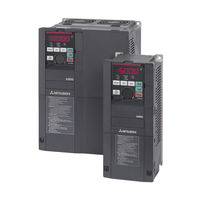
Mitsubishi Electric FR-F840-00250 Instruction Manual (940 pages)
FR-F800 series
Brand: Mitsubishi Electric
|
Category: Inverter
|
Size: 21.65 MB
Table of Contents
-
Instruction Manual
1
-
Safety Instructions
5
-
Table of Contents
13
-
1 Introduction
21
-
General Remarks
21
-
Product Checking and Accessories
23
-
Inverter Model
23
-
Accessory
24
-
How to Read the SERIAL Number
24
-
-
Component Names
25
-
Operation Steps
27
-
Related Manuals
28
-
-
2 Installation and Wiring
29
-
Peripheral Devices
29
-
Inverter and Peripheral Devices
29
-
Peripheral Devices
32
-
-
Removal and Reinstallation of the Operation Panel or the Front Covers
40
-
Installation of the Inverter and Enclosure Design
45
-
Inverter Installation Environment
45
-
Cooling System Types for Inverter Enclosure
48
-
Inverter Installation
49
-
Panel through Attachment Procedure
51
-
-
Terminal Connection Diagrams
53
-
CA Type
53
-
FM Type
55
-
CA Type (FR-F800-E)
57
-
FM Type (FR-F800-E)
59
-
-
Main Circuit Terminals
61
-
Details on the Main Circuit Terminals
61
-
Terminal Layout of the Main Circuit Terminals, Wiring of Power Supply
62
-
And the Motor
62
-
-
Applicable Cables and the Wiring Length
65
-
Earthing (Grounding) Precautions
72
-
-
Control Circuit
74
-
Details on the Control Circuit Terminals
74
-
Control Logic (Sink/Source) Change
78
-
Wiring of Control Circuit
81
-
Wiring Precautions
85
-
When Using Separate Power Supplies for the Control Circuit
86
-
When Supplying 24 V External Power to the Control Circuit
89
-
Safety Stop Function
92
-
-
Communication Connectors and Terminals
95
-
PU Connector
95
-
USB Connector
96
-
Terminal Block (Not for FR-F800-E)
98
-
-
Connection of Stand-Alone Option Units
99
-
Connection of the Brake Unit (FR-BU2)
99
-
Connection of the Brake Unit (FR-BU)
102
-
Connection of the Brake Unit (BU Type)
103
-
Connection of the High Power Factor Converter (FR-HC2)
104
-
Connection of the Power Regeneration Common Converter (FR-CV)
106
-
Connection of the Power Regeneration Converter (MT-RC)
107
-
Connection of the DC Reactor (FR-HEL)
108
-
Installing a Communication Option (FR-F800-E)
109
-
-
System Configuration for Ethernet Communication (FR-F800-E)
110
-
Ethernet Communication Overview
110
-
Ethernet Connector
111
-
Removal of the Ethernet Board
113
-
-
-
3 Precautions for Use of the Inverter
115
-
Electro-Magnetic Interference (EMI) and Leakage Currents
115
-
Leakage Currents and Countermeasures
115
-
Countermeasures against Inverter-Generated EMI
120
-
Built-In EMC Filter
123
-
-
Power Supply Harmonics
125
-
Harmonic Suppression Guidelines
126
-
-
Installation of a Reactor
130
-
Power-OFF and Magnetic Contactor (MC)
131
-
Countermeasures against Deterioration of the 400 V Class Motor Insulation
133
-
Checklist before Starting Operation
134
-
Failsafe System Which Uses the Inverter
137
-
-
4 Basic Operation
141
-
Operation Panel (FR-DU08)
141
-
Components of the Operation Panel (FR-DU08)
141
-
Basic Operation of the Operation Panel
143
-
Correspondences between Digital and Actual Characters
145
-
Changing the Parameter Setting Value
146
-
-
Monitoring the Inverter Status
147
-
Monitoring of Output Current and Output Voltage
147
-
First Monitored Item
147
-
Displaying the Set Frequency
148
-
-
Easy Operation Mode Setting (Easy Setting Mode)
149
-
Frequently-Used Parameters (Simple Mode Parameters)
151
-
Simple Mode Parameter List
151
-
-
Basic Operation Procedure (PU Operation)
153
-
Operating at the Set Frequency (Example: Operating at 30 Hz)
153
-
Using the Setting Dial Like a Potentiometer to Perform Operation
155
-
Setting the Frequency by Switches (Multi-Speed Setting)
156
-
Setting the Frequency with Analog Signals (Voltage Input)
158
-
Using an Analog Signal (Current Input) to Give a Frequency Command
160
-
-
Basic Operation Procedure (External Operation)
162
-
Using the Frequency Set by the Operation Panel
162
-
Setting the Frequency by Switches (Multi-Speed Setting) (Pr. 4 to Pr. 6)
164
-
Setting the Frequency with Analog Signals (Voltage Input)
166
-
Changing the Frequency (60 Hz, Initial Value) at the Maximum Voltage Input
167
-
(5 V, Initial Value)
167
-
-
Using an Analog Signal (Current Input) to Give a Frequency Command
168
-
Changing the Frequency (60 Hz, Initial Value) at the Maximum Current Input
169
-
(At 20 Ma, Initial Value)
169
-
-
-
Basic Operation Procedure (JOG Operation)
170
-
Performing JOG Operation Using External Signals
170
-
JOG Operation from the Operation Panel
171
-
-
-
5 Parameters
173
-
Parameter List
174
-
Parameter List (by Number)
174
-
Group Parameter Display
198
-
Parameter List (by Function Group)
200
-
-
Control Method
211
-
Changing the Control Method
213
-
Selecting the Advanced Magnetic Flux Vector Control
217
-
Selecting the PM Motor Control
220
-
-
Speed Control under PM Motor Control
225
-
Setting Procedure of PM Motor Control
226
-
Performing High-Accuracy, Fast-Response Control
227
-
Troubleshooting in the Speed Control
230
-
Torque Detection Filter
231
-
-
E) Environment Setting Parameters
232
-
Real Time Clock Function
233
-
Reset Selection/Disconnected PU Detection/Pu Stop Selection
235
-
PU Display Language Selection
239
-
Buzzer Control
239
-
PU Contrast Adjustment
239
-
Display-Off Mode
240
-
Resetting USB Host Errors
240
-
Setting Dial Potentiometer Mode/Key Lock Operation Selection
241
-
Frequency Change Increment Amount Setting
242
-
Multiple Rating Setting
243
-
Using the Power Supply Exceeding 480 V
244
-
Parameter Write Selection
244
-
Password Function
248
-
Free Parameter
252
-
Setting Multiple Parameters as a Batch
252
-
Extended Parameter Display and User Group Function
257
-
PWM Carrier Frequency and Soft-PWM Control
260
-
Inverter Parts Life Display
263
-
Maintenance Timer Alarm
267
-
Current Average Value Monitor Signal
269
-
-
F) Setting of Acceleration/Deceleration Time and Acceleration/Deceleration Pattern
273
-
Setting the Acceleration and Deceleration Time
274
-
Acceleration/Deceleration Pattern
279
-
Remote Setting Function
283
-
Starting Frequency and Start-Time Hold Function
287
-
Minimum Motor Speed Frequency
289
-
-
D) Operation Command and Frequency Command
290
-
Operation Mode Selection
291
-
Operation Mode
293
-
Startup in Network Operation Mode at Power-ON
300
-
During Communication Operation
302
-
-
Reverse Rotation Prevention Selection
311
-
Frequency Setting Via Pulse Train Input
312
-
JOG Operation
316
-
Operation by Multi-Speed Setting
318
-
-
H) Protective Function Parameter
321
-
Motor Overheat Protection (Electronic Thermal O/L Relay)
322
-
Cooling Fan Operation Selection
332
-
Earth (Ground) Fault Detection at Start
333
-
Varying the Activation Level of the Undervoltage Protective Function
333
-
Initiating a Protective Function
334
-
I/O Phase Loss Protection Selection
335
-
Retry Function
336
-
Emergency Drive (Fire Mode)
339
-
Limiting the Output Frequency (Maximum/Minimum Frequency)
348
-
Avoiding the Mechanical Resonance Points (Frequency Jump)
350
-
Stall Prevention Operation
352
-
Load Characteristics Fault Detection
361
-
Motor Overspeeding Detection
366
-
-
M) Monitor Display and Monitor Output Signal
367
-
Speed Display and Rotations Per Minute Setting
368
-
Monitor Indicator Selection Using Operation Panel or Via Communication
370
-
Monitor Display Selection for Terminals FM/CA and am
383
-
Adjusting Terminals FM/CA and am
390
-
Energy Saving Monitor
396
-
Output Terminal Function Selection
403
-
Output Frequency Detection
412
-
Output Current Detection Function
416
-
Output Torque Detection
418
-
Remote Output Function
419
-
Analog Remote Output Function
421
-
Fault Code Output Selection
424
-
Pulse Train Output of Output Power
425
-
Detection of Control Circuit Temperature
426
-
-
T) Multi-Function Input Terminal Parameters
427
-
Analog Input Selection
427
-
Analog Input Terminal (Terminal 1, 4) Function Assignment
432
-
Analog Input Compensation
433
-
Analog Input Responsiveness and Noise Elimination
436
-
Frequency Setting Voltage (Current) Bias and Gain
438
-
Bias and Gain for Voltage (Current) Setting of Stall Prevention Operation Level
445
-
Checking of Current Input on Analog Input Terminal
452
-
Input Terminal Function Selection
457
-
Inverter Output Shutoff Signal
461
-
Selecting Operation Condition of the Second Function Selection Signal (RT)
463
-
Start Signal Operation Selection
465
-
-
C) Motor Constant Parameters
469
-
Applied Motor
469
-
Offline Auto Tuning
475
-
Offline Auto Tuning for a PM Motor (Motor Constants Tuning)
488
-
Online Auto Tuning
499
-
-
A) Application Parameters
504
-
Electronic Bypass Function
505
-
Self Power Management
514
-
Traverse Function
518
-
Cleaning Function
520
-
PID Control
525
-
PID Gain Tuning
545
-
Changing the Display Increment of Numerical Values Used in PID Control
553
-
PID Pre-Charge Function
557
-
Multi-Pump Function (Advanced PID Function)
564
-
PID Control Enhanced Functions
576
-
Automatic Restart after Instantaneous Power Failure
587
-
Flying Start with an Induction Motor
587
-
-
Automatic Restart after Instantaneous Power Failure
595
-
Flying Start with an IPM Motor
595
-
-
Offline Auto Tuning for a Frequency Search
598
-
Power Failure Time Deceleration-To-Stop Function
604
-
PLC Function
611
-
Trace Function
615
-
-
N) Operation Via Communication and Its Settings
624
-
Wiring and Configuration of PU Connector
625
-
Wiring and Configuration of RS-485 Terminals
627
-
Initial Setting of Operation Via Communication
631
-
Initial Settings and Specifications of RS-485 Communication
639
-
Mitsubishi Inverter Protocol (Computer Link Communication)
641
-
Error Code
647
-
MODBUS® RTU Communication Specification
660
-
Bacnet MS/TP Protocol
678
-
Alarm History
690
-
Initial Settings and Specifications of Ethernet Communication (FR-F800-E)
694
-
MELSOFT / FA Product Connection
702
-
USB Device Communication
703
-
Automatic Connection with GOT
704
-
-
G) Control Parameters
706
-
Manual Torque Boost
707
-
Base Frequency, Voltage
709
-
Load Pattern Selection
711
-
Energy Saving Control
713
-
Adjustable 5 Points V/F
714
-
SF-PR Slip Amount Adjustment Mode
716
-
DC Injection Brake
717
-
Output Stop Function
720
-
Stop Selection
722
-
Regenerative Brake Selection and DC Feeding Mode
724
-
Regeneration Avoidance Function
732
-
Increased Magnetic Excitation Deceleration
736
-
Slip Compensation
738
-
Speed Smoothing Control
739
-
-
Parameter Clear / All Parameter Clear
740
-
Copying and Verifying Parameters on the Operation Panel
742
-
Parameter Copy
743
-
Parameter Verification
744
-
-
Copying and Verifying Parameters Using USB Memory
745
-
Checking Parameters Changed from Their Initial Values (Initial Value Change List)
749
-
Ethernet Communication (FR-F800-E)
750
-
Slmp
750
-
Communication Procedure
751
-
Modbus®/Tcp
765
-
CC-Link IE Field Network Basic (FR-F800-E)
782
-
Programming Examples
797
-
Instructions
806
-
-
Inverter-To-Inverter Link Function (FR-F800-E)
807
-
-
6 Protective Functions
813
-
Inverter Fault and Alarm Indications
813
-
Reset Method for the Protective Functions
814
-
Check and Clear of the Faults History
815
-
Check for the Faults History
815
-
Faults History Clearing Procedure
816
-
-
The List of Fault Displays
817
-
Causes and Corrective Actions
821
-
Error Message
821
-
Warning
825
-
Alarm
829
-
Fault
830
-
Other Messages
844
-
-
Check First When You Have a Trouble
845
-
Motor Does Not Start
845
-
Motor or Machine Is Making Abnormal Acoustic Noise
848
-
Inverter Generates Abnormal Noise
849
-
Motor Generates Heat Abnormally
849
-
Motor Rotates in the Opposite Direction
849
-
Speed Greatly Differs from the Setting
850
-
Acceleration/Deceleration Is Not Smooth
850
-
Speed Varies During Operation
851
-
Operation Mode Is Not Changed Properly
852
-
Operation Panel (FR-DU08) Display Is Not Operating
852
-
Motor Current Is too Large
852
-
Speed Does Not Accelerate
853
-
Unable to Write Parameter Setting
854
-
Power Lamp Is Not Lit
854
-
-
-
7 Precautions for Maintenance and Inspection
855
-
Inspection Item
855
-
Daily Inspection
855
-
Periodic Inspection
855
-
Daily and Periodic Inspection
856
-
Checking the Inverter and Converter Modules
858
-
Cleaning
859
-
Replacement of Parts
859
-
Inverter Replacement
865
-
-
Measurement of Main Circuit Voltages, Currents and Powers
866
-
Measurement of Powers
869
-
Measurement of Voltages and Use of PT
870
-
Measurement of Currents
871
-
Use of CT and Transducer
872
-
Measurement of Inverter Input Power Factor
872
-
Measurement of Converter Output Voltage (Across Terminals P and N)
872
-
Measurement of Inverter Output Frequency
872
-
Insulation Resistance Test Using Megger
873
-
Pressure Test
873
-
-
-
8 Specifications
875
-
Inverter Rating
875
-
V Class
876
-
-
Motor Rating
878
-
Premium High-Efficiency IPM Motor [MM-EFS (1500 R/Min Specification)]
878
-
Premium High-Efficiency IPM Motor [MM-EFS (3000 R/Min Specification)]
880
-
Premium High-Efficiency IPM Motor [MM-THE4 (1500 R/Min Specification)]
882
-
-
Common Specifications
884
-
Outline Dimension Drawings
886
-
Inverter Outline Dimension Drawings
886
-
Dedicated Motor Outline Dimension Drawings
895
-
-
-
A Appendix
901
-
For Customers Replacing the Conventional Model with this Inverter
901
-
Replacement of the FR-F700(P) Series
901
-
A.1 for Customers Replacing the Conventional Model with this Inverter
901
-
Replacement of the FR-F500(L) Series
902
-
-
Specification Comparison between PM Motor Control and Induction Motor Control
903
-
Parameters (Functions) and Instruction Codes under Different Control Methods
905
-
Under Different Control Methods
923
-
-
For Customers Using HMS Network Options
925
-
List of Inverter Monitored Items / Command Items
925
-
-
EC Declarations of Conformity
928
-
FR-F820/FR-F840/FR-F842 Series
928
-
A.6 EC Declarations of Conformity
928
-
-
Advertisement
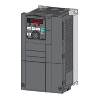
Mitsubishi Electric FR-F840-00250 Instruction Manual (660 pages)
FR-F800 series
Brand: Mitsubishi Electric
|
Category: Inverter
|
Size: 16.46 MB
Table of Contents
-
Inverter Fr-F800 Instruction Manual (Detailed)
2
-
Table of Contents
2
-
Safety Instructions
9
-
Fire Prevention
10
-
-
-
Chapter 1 Introduction
16
-
Product Checking and Accessories
18
-
Serial Number
19
-
Component Names
20
-
Operation Steps
22
-
About the Related Manuals
23
-
-
Chapter 2 Installation and Wiring
24
-
Peripheral Devices
25
-
Peripheral Devices
27
-
Removal and Reinstallation of the Operation Panel or the Front Covers
31
-
Installation of the Inverter and Enclosure Design
35
-
-
Amount of Heat Generated by the Inverter
38
-
Cooling System Types for Inverter Enclosure
39
-
Inverter Installation
40
-
Protruding the Heat Sink through a Panel
42
-
Terminal Connection Diagrams
44
-
Main Circuit
46
-
-
Control Circuit
46
-
Main Circuit Terminals
48
-
-
Main Circuit Terminal Layout and Wiring to Power Supply and Motor
49
-
Applicable Cables and Wiring Length
51
-
Earthing (Grounding) Precautions
58
-
Control Circuit
59
-
-
Control Logic (Sink/Source) Change
63
-
Wiring of Control Circuit
64
-
Wiring Precautions
67
-
When Supplying 24 V External Power to the Control Circuit
70
-
Safety Stop Function
71
-
Communication Connectors and Terminals
74
-
-
USB Connector
75
-
RS-485 Terminal Block
76
-
Connection of Stand-Alone Option Units
77
-
-
Connection of the Brake Unit (FR-BU)
79
-
Connection of the High Power Factor Converter (FR-HC2)
80
-
Connection of the Power Regeneration Common Converter (FR-CV)
81
-
Connection of the Power Regeneration Converter (MT-RC)
82
-
-
Chapter 3 Precautions for Use of the Inverter 4 5
84
-
Electro-Magnetic Interference (EMI) and Leakage Currents
85
-
Techniques and Measures for Electromagnetic Compatibility (EMC)
87
-
Built-In EMC Filter
89
-
Power Supply Harmonics
92
-
Installation of a Reactor
96
-
Power Shutdown and Magnetic Contactor (MC)
97
-
Countermeasures against Deterioration of the 400 V Class Motor Insulation
99
-
Checklist before Starting Operation
100
-
Failsafe System Which Uses the Inverter
103
-
-
-
Chapter 4 Basic Operation
106
-
Operation Panel (FR-DU08)
107
-
Basic Operation of the Operation Panel
109
-
Digital Characters and Their Corresponding Printed Equivalents
110
-
Changing the Parameter Setting Value
111
-
Monitoring the Inverter
112
-
Easy Setting of the Inverter Operation Mode
113
-
Frequently-Used Parameters (Simple Mode Parameters)
115
-
Basic Operation Procedure (PU Operation)
117
-
-
Perform PU Operation Using the Setting Dial Like a Potentiometer
118
-
Setting the Frequency with Switches (Multi-Speed Setting)
119
-
Setting the Frequency Using an Analog Signal (Voltage Input)
120
-
Setting the Frequency Using an Analog Signal (Current Input)
121
-
Basic Operation Procedure (External Operation)
123
-
-
Setting the Frequency and Giving a Start Command with Switches (Multi-Speed Setting) (Pr.4 to Pr.6)
124
-
Setting the Frequency Using an Analog Signal (Voltage Input)
125
-
-
Changing the Frequency (60 Hz, Initial Value) at the Maximum Voltage Input (5 V, Initial Value)
127
-
Setting the Frequency Using an Analog Signal (Current Input)
128
-
-
Changing the Frequency (60 Hz, Initial Value) at the Maximum Current Input (at 20 Ma, Initial Value)
129
-
Basic Operation Procedure (JOG Operation)
130
-
-
Giving a Start Command from the Operation Panel for JOG Operation
131
-
-
Chapter 5 Parameters
132
-
Parameter List
133
-
Use of a Function Group Number for the Identification of Parameters
157
-
Parameter List (by Function Group Number)
159
-
Control Method
168
-
Changing the Control Method and Mode
170
-
Selecting the Advanced Magnetic Flux Vector Control
173
-
Selecting the PM Motor Control
175
-
Speed Control under PM Motor Control
181
-
Performing High-Accuracy, Fast-Response Control (Gain Adjustment for PM Motor Control)
183
-
Troubleshooting in the Speed Control
185
-
Torque Detection Filter
186
-
E) Environment Setting Parameters
187
-
Real Time Clock Function
188
-
Reset Selection / Disconnected PU Detection / PU Stop Selection
189
-
PU Display Language Selection
192
-
Direct Setting
193
-
Frequency Change Increment Amount Setting
194
-
Multiple Rating Setting
195
-
Using the Power Supply Exceeding 480 VAC
196
-
Parameter Write Selection
197
-
Password
199
-
Free Parameter
201
-
Extended Parameter Display and User Group Function
205
-
PWM Carrier Frequency and Soft-PWM Control
208
-
Inverter Parts Life Display
209
-
Maintenance Timer Alarm
213
-
Current Average Value Monitor Signal
214
-
F) Setting of Acceleration/Deceleration Time and Acceleration/Deceleration Pattern
217
-
Control Block Diagram
218
-
-
Acceleration/Deceleration Pattern
220
-
Remote Setting Function
223
-
Starting Frequency and Start-Time Hold Function
226
-
Minimum Motor Speed Frequency at the Motor Start up
227
-
D) Operation Command and Frequency Command
229
-
Startup of the Inverter in Network Operation Mode at Power-ON
238
-
Start Command Source and Frequency Command Source During Communication Operation
240
-
Reverse Rotation Prevention Selection
246
-
JOG Operation
249
-
Operation by Multi-Speed Setting
250
-
H) Protective Function Parameter
253
-
Cooling Fan Operation Selection
259
-
Earth (Ground) Fault Detection at Start
260
-
Varying the Activation Level of the Undervoltage Protective Function
261
-
Retry Function
262
-
Emergency Drive
264
-
Limiting the Output Frequency (Maximum/Minimum Frequency)
272
-
Avoiding Machine Resonance Points (Frequency Jump)
273
-
Stall Prevention Operation
274
-
Load Characteristics Fault Detection
282
-
Motor Overspeeding Detection
286
-
M) Item and Output Signal for Monitoring
287
-
Monitor Item Selection on Operation Panel or Via Communication
289
-
Monitor Display Selection for Terminals FM/CA and am
298
-
Adjustment of Terminal FM/CA and Terminal am
303
-
Energy Saving Monitoring
307
-
Output Terminal Function Selection
313
-
Output Signal List
314
-
-
Output Frequency Detection
320
-
Output Current Detection Function
322
-
Output Torque Detection Function
324
-
Remote Output Function
325
-
Analog Remote Output Function
326
-
Fault Code Output Selection
328
-
Pulse Train Output to Announce Cumulative Output Energy
329
-
Detection of Control Circuit Temperature
330
-
T) Multi-Function Input Terminal Parameters
331
-
Analog Input Terminal (Terminal 1, 4) Function Assignment
335
-
Analog Input Compensation
336
-
Response Level of Analog Input and Noise Elimination
338
-
Frequency Setting Voltage (Current) Bias and Gain
340
-
Bias and Gain for Voltage (Current) Setting of Stall Prevention Operation Level
345
-
Checking of Current Input on Analog Input Terminal
351
-
Input Terminal Function Selection
356
-
Inverter Output Shutoff
358
-
Selecting the Condition to Activate the Second Function Selection (RT) Signal
359
-
Start Signal Operation Selection
360
-
(C) Motor Constant Parameters
363
-
Offline Auto Tuning
367
-
Offline Auto Tuning for a PM Motor (Motor Constant Tuning)
376
-
Online Auto Tuning
383
-
A) Application Parameters
387
-
Electronic Bypass Function
388
-
Self Power Management
394
-
Start Count Monitor
396
-
Traverse Function
397
-
Cleaning Function
399
-
PID Control
402
-
PID Gain Tuning
418
-
Changing the Display Increment of Numerical Values Used in PID Control
424
-
PID Pre-Charge Function
426
-
Multi-Pump Function (Advanced PID Function)
431
-
PID Control Enhanced Functions
440
-
Automatic Restart after Instantaneous Power Failure/Flying Start with an Induction Motor
447
-
Automatic Restart after Instantaneous Power Failure/Flying Start with a PM Motor
452
-
Offline Auto Tuning for a Frequency Search
455
-
Power Failure Time Deceleration-To-Stop Function
459
-
PLC Function
463
-
Trace Function
466
-
N) Communication Operation Parameters
474
-
Wiring and Configuration of RS-485 Terminals
476
-
Initial Setting of Operation Via Communication
479
-
Initial Settings and Specifications of RS-485 Communication
483
-
Mitsubishi Inverter Protocol (Computer Link Communication)
485
-
Setting Items and Set Data
494
-
-
MODBUS RTU Communication Specification
499
-
Message Format
500
-
Function Code List
502
-
-
Bacnet MS/TP Protocol
512
-
USB Device Communication
524
-
Backup/Restore
526
-
(G) Control Parameters
528
-
Base Frequency Voltage
529
-
Load Pattern Selection
531
-
Excitation Current Low-Speed Scaling Factor
532
-
Energy Saving Control
533
-
Adjustable 5 Points V/F
534
-
SF-PR Slip Amount Adjustment Mode
535
-
DC Injection Brake
536
-
Output Stop Function
537
-
Stop Selection
539
-
Regenerative Brake Selection and DC Feeding Mode
540
-
Regeneration Avoidance Function
546
-
Increased Magnetic Excitation Deceleration
548
-
Slip Compensation
549
-
Speed Smoothing Control
550
-
Parameter Clear / All Parameter Clear
552
-
5.15 Copying and Verifying Parameters on the Operation Panel
553
-
Parameter Verification
555
-
Copying and Verifying Parameters Using a USB Memory
556
-
Checking Parameters Changed from Their Initial Values (Initial Value Change List)
560
-
Chapter 6 PROTECTIVE FUNCTIONS
563
-
Reset Method for the Protective Functions
564
-
Check and Clear of the Fault History
565
-
List of Fault Displays
567
-
Causes and Corrective Actions
569
-
Check First When You Have a Trouble
586
-
Motor or Machine Is Making Abnormal Acoustic Noise
589
-
Motor Rotates in the Opposite Direction
590
-
Speed Varies During Operation
591
-
Operation Panel (FR-DU08) Display Is Not Operating
592
-
Speed Does Not Accelerate
593
-
Power Lamp Is Not Lit
594
-
-
Chapter 7 PRECAUTIONS for MAINTENANCE and
597
-
Inspection
597
-
Daily and Periodic Inspection
598
-
Checking the Inverter and Converter Modules
599
-
Cleaning
600
-
Removal and Reinstallation of the Control Circuit Terminal Block
606
-
Measurement of Main Circuit Voltages, Currents, and Powers
607
-
Measurement of Powers
609
-
Use of CT and Transducer
610
-
Insulation Resistance Test Using Megger
611
-
-
Chapter 8 SPECIFICATIONS
613
-
Inverter Rating
613
-
Motor Rating
616
-
Premium High-Efficiency IPM Motor [MM-EFS (3000 R/Min Specification)]
618
-
Premium High-Efficiency IPM Motor [MM-THE4]
619
-
Common Specifications
621
-
Outline Dimension Drawings
623
-
Dedicated Motor Outline Dimension Drawings
631
-
-
Chapter 9 APPENDIX
635
-
For Customers Replacing the Conventional Model with this Inverter
635
-
Replacement of the FR-F500(L) Series
636
-
Parameters (Functions) and Instruction Codes under Different Control Methods
639
-
For Customers Using HMS Network Options
655
-
-

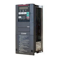
Mitsubishi Electric FR-F840-00250 Instruction Manual (91 pages)
Brand: Mitsubishi Electric
|
Category: Inverter
|
Size: 7.65 MB
Table of Contents
-
Inverter Model
3
-
Inverter Placement
3
-
Installation Environment
3
-
Outline Dimensions
4
-
Terminal Connection Diagrams
5
-
Main Circuit Terminals
7
-
Terminal Layout
11
-
Control Circuit Terminal
11
-
Wiring Method
11
-
Wiring Precautions
12
-
Control Logic (Sink/Source) Change
12
-
When Supplying 24 V External Power to the Control Circuit
12
-
Safety Stop Function
13
-
Function Description
13
-
Connection Diagram
13
-
Failsafe System Which Uses the Inverter
14
-
Precautions for Use of the Inverter
15
-
Drive the Motor
16
-
Components of the Operation Panel (FR-DU08)
16
-
Basic Operation (Factory Setting)
17
-
Parameter List
18
-
Troubleshooting
23
-
Reset Method for the Protective Functions
23
-
List of Fault Displays
24
-
Specifications
25
-
Appendix 1 Instructions for Compliance with the EU Directives
27
-
EMC Directive
27
-
Appendix 2 Instructions for UL and Cul
29
-
General Precaution
29
-
Installation
29
-
Motor Overload Protection
30
-
PID Control Enhanced Functions
37
Advertisement

Mitsubishi Electric FR-F840-00250 Instruction Manual (88 pages)
Brand: Mitsubishi Electric
|
Category: Air Conditioner
|
Size: 8.08 MB
Table of Contents
-
Table of Contents
30
-
Inverter Installation and Precautions
32
-
Wiring
33
-
Basic Operation
38
-
Failsafe System Which Uses the Inverter
40
-
Precautions for Use of the Inverter
40

Mitsubishi Electric FR-F840-00250 Installation Manuallines (64 pages)
FR-F800 series
Brand: Mitsubishi Electric
|
Category: Inverter
|
Size: 3.91 MB
Table of Contents
-
Table of Contents
1
-
Fire Prevention
3
-
Installation and Instructions
7
-
Installation of the Inverter
8
-
Wiring
10
-
Terminal Layout and Wiring
18
-
Control Circuit Terminals
25
-
Terminal Layout
25
-
Wiring Method
25
-
Wiring Precautions
26
-
Connection Diagram
28
-
Function Description
28
-
-
Failsafe of the System Which Uses the Inverter
30
-
Precautions for Use of the Inverter
31
-
Basic Operation
33
-
Parameter List
35
-
Troubleshooting
50
-
Reset Method of Protective Function
51
-
List of Alarm Display
51
-
-
Specifications
53
-
Outline Dimensions
56
-
Appendix
58
-
-
Aappendix
58
Mitsubishi Electric FR-F840-00250 Installation Manuallines (64 pages)
Brand: Mitsubishi Electric
|
Category: Inverter
|
Size: 3.89 MB
Table of Contents
-
Table of Contents
1
-
Installation and Instructions
7
-
Wiring
10
-
Failsafe of the System Which Uses the Inverter
30
-
Precautions for Use of the Inverter
31
-
Basic Operation
33
-
Troubleshooting
50
-
Specifications
53
-
Aappendix
58
Advertisement
Related Products
-
Mitsubishi Electric FR-F840-00250(11K)
-
Mitsubishi Electric FR-F840-00083
-
Mitsubishi Electric FR-F840-00170
-
Mitsubishi Electric FR-F840-00470
-
Mitsubishi Electric FR-F840-00083(3.7K)
-
Mitsubishi Electric FR-F840-00170(7.5K)
-
Mitsubishi Electric FR-F840-00310(15K)
-
Mitsubishi Electric FR-F840-00930(45K)
-
Mitsubishi Electric FR-F840-00170-E2-60
-
Mitsubishi Electric FR-F840-00023-06830-E
Mitsubishi Electric Categories
![]()
Air Conditioner
Controller
![]()
Projector
Inverter
Heat Pump
More Mitsubishi Electric Manuals


 Цена за 1 шт., с НДС
Цена: 99 100.00 ₽
Работаем с юридическими и физическими лицами
Брэнд:
Mitsubishi Electric
Модель:
FR-F840-00380-2-60
Выбрать модель
Перегрузочная способность:
110% в течение 60 сек.
Подробные технические характеристики
Если у вас возникли трудности или вы сомневаетесь в своем выборе,
то позвоните нам по телефону — 8 (4932) 32-45-05.
Или закажите обратный звонок
Аналоги:

EI-9011-001H
Мощность, кВт: 1,1
Номинальный ток, А: 3,4

EI-9011-002H
Мощность, кВт: 1,5
Номинальный ток, А: 4,8

EI-9011-003H
Мощность, кВт: 2,2
Номинальный ток, А: 6,2

EI-9011-005H
Мощность, кВт: 3,7
Номинальный ток, А: 8

EI-9011-007H
Мощность, кВт: 5,5
Номинальный ток, А: 14

EI-9011-010H
Мощность, кВт: 7,5
Номинальный ток, А: 18

N700E-004SF
Мощность, кВт: 0,4
Номинальный ток, А: 3

N700E-037HF
Мощность, кВт: 3,7
Номинальный ток, А: 9,2

N700E-055HF
Мощность, кВт: 5,5
Номинальный ток, А: 7,9

N700E-075HF
Мощность, кВт: 7,5
Номинальный ток, А: 10,5

N700E-110HF
Мощность, кВт: 11
Номинальный ток, А: 15,1

N700E-150HF
Мощность, кВт: 15
Номинальный ток, А: 21,1

CIMR-VCBA0001BAA
Мощность, кВт: 0,2
Номинальный ток, А: 1,2

CIMR-VCBA0002BAA
Мощность, кВт: 0,4
Номинальный ток, А: 1,9

CIMR-VCBA0003BAA
Мощность, кВт: 0,75
Номинальный ток, А: 3,3

CIMR-VCBA0006BAA
Мощность, кВт: 1,1
Номинальный ток, А: 6

CIMR-VCBA0010BAA
Мощность, кВт: 2,2
Номинальный ток, А: 9,6

CIMR-VCBA0012BAA
Мощность, кВт: 3
Номинальный ток, А: 12

131N0191
Мощность, кВт: 11
Номинальный ток, А:
131N0193
Мощность, кВт: 15
Номинальный ток, А:
131L9872
Мощность, кВт: 22
Номинальный ток, А:
131L9873
Мощность, кВт: 30
Номинальный ток, А:
131L9867
Мощность, кВт: 5,5
Номинальный ток, А:
131N0187
Мощность, кВт: 5,5
Номинальный ток, А:

ESQ-760-4T0220G-0300P
Мощность, кВт: 22
Номинальный ток, А: 45

ESQ-760-4T0370G-0450P
Мощность, кВт: 37
Номинальный ток, А: 75

ESQ-760-4T0300G-0370P
Мощность, кВт: 30
Номинальный ток, А: 60

ESQ-760-4T0450G-0550P
Мощность, кВт: 45
Номинальный ток, А: 91

ESQ-760-4T0550G-0750P
Мощность, кВт: 55
Номинальный ток, А: 112

ESQ-760-4T0185G-0220P
Мощность, кВт: 18,5
Номинальный ток, А: 37

VFD002E21A
Мощность, кВт: 0,2
Номинальный ток, А: 1,6

VFD004E21A
Мощность, кВт: 0,4
Номинальный ток, А: 2,5

VFD004E43A
Мощность, кВт: 0,4
Номинальный ток, А: 1,5

VFD007E21A
Мощность, кВт: 0,75
Номинальный ток, А: 4,2

VFD007E43A
Мощность, кВт: 0,75
Номинальный ток, А: 2,5

VFD015E21A
Мощность, кВт: 1,5
Номинальный ток, А: 7,5

ACS55-01E-01A4-1
Мощность, кВт: 0,18
Номинальный ток, А: 1,4

ACS55-01E-01A4-2
Мощность, кВт: 0,18
Номинальный ток, А: 1,4

ACS55-01E-02A2-1
Мощность, кВт: 0,37
Номинальный ток, А: 2,2

ACS55-01E-02A2-2
Мощность, кВт: 0,37
Номинальный ток, А: 2,2

ACS55-01E-04A3-2
Мощность, кВт: 0,75
Номинальный ток, А: 4,3

ACS55-01E-07A6-2
Мощность, кВт: 1,5
Номинальный ток, А: 7,6

FCI-G3.7-4B
Мощность, кВт: 3,7
Номинальный ток, А: 8,8

FCI-P5.5-4B
Мощность, кВт: 5,5
Номинальный ток, А: 13

FCI-G5.5-4B
Мощность, кВт: 5,5
Номинальный ток, А: 13

FCI-P7.5-4B
Мощность, кВт: 7,5
Номинальный ток, А: 17

FCI-G7.5-4B
Мощность, кВт: 7,5
Номинальный ток, А: 17

FCI-G11-4BF
Мощность, кВт: 11
Номинальный ток, А: 25

FR-F840-00023-E2-60
Мощность, кВт: 0,75
Номинальный ток, А: 2,1

FR-F840-00023-2-60
Мощность, кВт: 0,75
Номинальный ток, А: 2,1

FR-F840-00038-E2-60
Мощность, кВт: 1,5
Номинальный ток, А: 3,5

FR-F840-00038-2-60
Мощность, кВт: 1,5
Номинальный ток, А: 3,5

FR-F840-00052-E2-60
Мощность, кВт: 2,2
Номинальный ток, А: 4,8

FR-F840-00052-2-60
Мощность, кВт: 2,2
Номинальный ток, А: 4,8

6SE6420-2UC11-2AA1
Мощность, кВт: 0,12
Номинальный ток, А: 0,9

6SE6420-2UC12-5AA1
Мощность, кВт: 0,25
Номинальный ток, А: 1,7

6SE6420-2UC13-7AA1
Мощность, кВт: 0,37
Номинальный ток, А: 2,3

6SE6420-2UC15-5AA1
Мощность, кВт: 0,55
Номинальный ток, А: 3

6SE6420-2UC17-5AA1
Мощность, кВт: 0,75
Номинальный ток, А: 3,9

6SE6420-2UC21-1BA1
Мощность, кВт: 1,1
Номинальный ток, А: 5,5

ATV12H018F1
Мощность, кВт: 0,18
Номинальный ток, А: 1,4

ATV12H037F1
Мощность, кВт: 0,37
Номинальный ток, А: 2,4

ATV12H075F1
Мощность, кВт: 0,75
Номинальный ток, А: 4,2

ATV12H018M2
Мощность, кВт: 0,18
Номинальный ток, А: 1,4

ATV12H037M2
Мощность, кВт: 0,37
Номинальный ток, А: 2,4

ATV12H055M2
Мощность, кВт: 0,55
Номинальный ток, А: 3,5

ESMD251X2SFA
Мощность, кВт: 0,25
Номинальный ток, А: 3,4

ESMD371X2SFA
Мощность, кВт: 0,37
Номинальный ток, А: 5

ESMD551X2SFA
Мощность, кВт: 0,55
Номинальный ток, А: 6

ESMD751X2SFA
Мощность, кВт: 0,75
Номинальный ток, А: 9

ESMD152X2SFA
Мощность, кВт: 1,5
Номинальный ток, А: 14

ESMD222X2SFA
Мощность, кВт: 2,2
Номинальный ток, А: 21

3G3MX2-A4004-E CHN
Мощность, кВт: 0,4
Номинальный ток, А: 1,8

3G3MX2-A4007-E CHN
Мощность, кВт: 0,75
Номинальный ток, А: 3,4

3G3MX2-A4022-E CHN
Мощность, кВт: 2,2
Номинальный ток, А: 5,5

3G3MX2-A4015-E CHN
Мощность, кВт: 1,5
Номинальный ток, А: 4,8

3G3MX2-A4030-E CHN
Мощность, кВт: 3
Номинальный ток, А: 7,2

3G3MX2-A4040-E CHN
Мощность, кВт: 4
Номинальный ток, А: 9,2

ADV 1.50 M420-M
Мощность, кВт: 1,5
Номинальный ток, А: 2,1

ADV 2.20 M420-M
Мощность, кВт: 2,2
Номинальный ток, А: 3,8

ADV 4.00 M420-M
Мощность, кВт: 4
Номинальный ток, А: 5,1

ADV 5.50 M420-M
Мощность, кВт: 5,5
Номинальный ток, А: 9

ADV 7.50 M420-M
Мощность, кВт: 7,5
Номинальный ток, А: 13

ADV 11.0 M420-M
Мощность, кВт: 11
Номинальный ток, А: 17

VFD007CH23A-21
Мощность, кВт: 0,75
Номинальный ток, А: 2

VFD015CH23A-21
Мощность, кВт: 1,5
Номинальный ток, А: 8

VFD022CH23A-21
Мощность, кВт: 2,2
Номинальный ток, А: 11

VFD037CH23A-21
Мощность, кВт: 3,7
Номинальный ток, А: 17

VFD055CH23A-21
Мощность, кВт: 5,5
Номинальный ток, А: 25

VFD075CH23A-21
Мощность, кВт: 7,5
Номинальный ток, А: 33

NXP 0003 2A2H1SSS
Мощность, кВт: 0,55
Номинальный ток, А: 3,7

NXP 0004 2A2H1SSS
Мощность, кВт: 0,75
Номинальный ток, А: 4,8

NXP 0007 2A2H1SSS
Мощность, кВт: 1,1
Номинальный ток, А: 6,6

NXP 0008 2A2H1SSS
Мощность, кВт: 1,5
Номинальный ток, А: 7,8

NXP 0011 2A2H1SSS
Мощность, кВт: 2,2
Номинальный ток, А: 11

NXP 0012 2A2H1SSS
Мощность, кВт: 3
Номинальный ток, А: 12,5

VT100-0R4-1B
Мощность, кВт: 0,4
Номинальный ток, А: 5,4

VT100-0R7-1B
Мощность, кВт: 0,75
Номинальный ток, А: 8,2

VT100-1R5-1B
Мощность, кВт: 1,5
Номинальный ток, А: 14

VT100-2R2-1B
Мощность, кВт: 2,2
Номинальный ток, А: 24

VT100-0R7-3B
Мощность, кВт: 0,75
Номинальный ток, А: 3,4

VT100-1R5-3B
Мощность, кВт: 1,5
Номинальный ток, А: 5

PM150A-2S-0.4B
Мощность, кВт: 0,25
Номинальный ток, А: 2,5

PM150A-2S-0.2B
Мощность, кВт: 0,18
Номинальный ток, А: 1,6

PM150A-2S-0.7B
Мощность, кВт: 0,75
Номинальный ток, А: 9,2

PM150A-2S-1.1B
Мощность, кВт: 1,1
Номинальный ток, А: 11

PM150A-2S-1.5B
Мощность, кВт: 1,5
Номинальный ток, А: 15,5

PM150A-2S-2.2B
Мощность, кВт: 2,2
Номинальный ток, А: 24
Часто задаваемые вопросы
Выбрав раздел и тематику вопроса вы увидите ответы на часто задаваемые вопросы.
-
Раздел — Покупка оборудования
-
Раздел — Предоставление услуг
-
Заказ
-
Оплата
-
Доставка
-
Возврат / Обмен
Как сделать заказ на сайте?
1. Зайдите в каталог товаров
2. Выберите нужную категорию
3. Выберите интересующий товар
4. Нажмите кнопку «Купить» заполните все обязательные поля и нажмите «Отправить заказ на обработку. Менеджер вам перезвонит в рабочее время с 9 до 18:00
5. Либо нажмите кнопку «Добавить в заказ», потом нажмите еще раз на эту же кнопку, заполните все поля в форме справа и нажмите кнопку «Отправить заказ»
Как оплатить товар?
1. Для физических лиц оплата товара осуществляется по наличному расчёту.
2. От юридических лиц мы принимаем оплату по безналичному расчёту. Счет будет
отправлен по электронной почте*.
* Отгрузка товара производится при условии поступления денежных средств (100%
предоплата за товар). Возможна отсрочка платежа (условия обсуждаются индивидуально).
В каких случаях возможен возврат и обмен товара?
Если качество Товара не соответствует техническим условиям завода-изготовителя в
течение гарантийного срока Продавец обязуется по заявленной Покупателем рекламации
бесплатно устранить недостатки Товара или заменить его новым при соблюдении
Покупателем условий гарантийной эксплуатации и установки, определенных в
инструкциях и паспорте Товара и при условии сохранения паспорта, упаковки и товарного
вида, а также при наличии всех документов, подтверждающих факт совершения покупки
(товарный или кассовый чек).
Неисправности Товара, возникшие по причине нарушения Покупателем правил
хранения и эксплуатации, установки, монтажа устраняются за его счет (по отдельному
договору)
По согласованию с Продавцом Покупателю может быть предоставлено право
самостоятельно устранить неисправность Товара, либо привлечь к устранению
неисправности третьих лиц.
Если предоставленный Товар не соответствует технической документации на Товар о
комплектности либо ассортименте, то Покупатель вправе потребовать от Продавца
доукомплектования Товара либо (в случае несоблюдения условия об ассортименте), —
замены Товара.
Рекламация по некомплектности либо нарушению условий настоящего Договора
об ассортименте Товара может быть направлена в течение 10 (десять) дней со дня
фактической передачи Товара Покупателю либо иному грузополучателю, указанному
Покупателем.
Рекламация должна быть направлена Продавцу по факсу, с описанием
неисправностей, некомплектности либо несоблюдения условия об ассортименте Товара, а
также с указанием предполагаемых компонентов Товара, необходимых для устранения
неисправностей, некомплектности либо нарушения условия об ассортименте Товара.
Как получить ваш заказ?
Важно! Вместе с товаром Вам будет предоставлен универсальный передаточный
документ. В случае необходимости предоставления каких-либо иных документов Вам
необходимо предупредить об этом Вашего личного менеджера. При получении
товара Вам необходимо проверить заказ, убедившись в отсутствии видимых
повреждений и соответствии заявленного в документах количества.
Самовывоз.
г. Иваново, ул. Батурина, д.10
Доставка по г. Иваново.
Наш курьер доставит Вам нашу продукцию в любую точку г. Иваново. Стоимость
доставки 200р
Доставка по всей России.
По России наш товар доставляют транспортные компании (DHL, DPD, EMS Почта DHL, DPD, EMS Почта
России, FedEx, Logibox, Major Express, PickPoint, Pony Express, Байкал-сервис,
Гарантпост, Деловые Линии, Желдорэкспедиция, ПЭК, Энергия и др.), стоимость и
сроки доставки рассчитываются транспортной компанией.
-
Заказ
-
Оплата
-
Сервисный центр
Как заказать услугу на сайте?
1. Зайти на страницу интересующей услуги
2. Нажать кнопку «Оставить заявку»
3. Написать свой номер телефона и нажать кнопку «Жду звонка»
Либо позвонить по номеру 8 (4932) 32-45-05 заказать интересующую услугу
Сохраняется ли гарантия на отремонтированное оборудование?
Прежде всего необходимо различать гарантийный и негарантийный случаи при выходе из строя оборудования.
Гарантия на отремонтированное оборудование распространяется только в случае, если его эксплуатация и условия эксплуатации соответствуют паспортным данным.
Что же является негарантийным случаем?
В первую очередь это окончание гарантийного срока эксплуатации.
Например, для ПЧ производства ВЕСПЕР гарантийный срок составляет 3 года.
По истечении этого срока осуществляется негарантийный ремонт.
При этом гарантия предоставляется сроком 6 месяцев на замененные в процессе ремонта элементы ПЧ.
Если после ремонта выходит из строя другой элемент ПЧ, то гарантия после ремонта в этом случае будет только на этот другой элемент.
Как осуществляется оплата выполненных работ?
«Энергосервисный центр» работает по УСН и принимает оплату от юридических лиц по безналичной форме, путем перечисления денежных средств на расчетный счет, не более чем в течение 30 дней после подписания акта о приемке выполненных работ (форма № КС-2) и справки о стоимости выполненных работ и затрат (форма № КС-3), с обязательным приложением к ним актов на скрытые работы, подписанных двумя сторонами, согласно выставленным счету и счет – фактуре.
Все счета и КП выставляются с НДС 18%.
Уставные и регистрационные документы нашей компании для формирования договоров и участия в тендерах Вы всегда можете запросить у наших менеджеров.
По согласованию с Заказчиком допускается промежуточная оплата. Размер аванса и другие услoвия обговариваются индивидуально при каждом заказе с нашими менеджерами.
Ваша компания участвует в тендерах?
Да, наша компания принимает участие в государственных и коммерческих тендерах ежедневно.
У нас богатый опыт участия в аукционах, запросах котировок, открытых конкурсах и других формах электронных торгов.
Кроме этого, мы оказывает помощь государственным, муниципальным и коммерческим заказчикам в составлении технических заданий для конкурсной документации, а также предоставляем консультационные услуги по подбору оборудования.
Есть
вопрос?![]()
Мы с радостью ответим на все
интересующие вас вопросы!
Нажатием на кнопку я даю свое
согласие на обработку персональных
данных в соответствии с указанными
здесь условиями.

![]()
г. Иваново, ул. Батурина, 10

Inverter; Rated Power: 18,5kW; 3×380-500V;In max: 38A;(18,5kW; 38A);IP20
- TECHNICAL INFORMATION
- ADDITIONAL INFORMATION
- ENVIRONMENTAL
- Загрузки
FA-Inverter: Inverter
| Series | FR-F800 SERIES |
|---|---|
| Type | FR-F800-E INVERTER |
| Minimum Rated Voltage (V) | 380 |
| Min. Permissible Voltage (V) | 323 |
| Maximum Rated Voltage (V) | 500 |
| Max. Permissible Voltage (V) | 550 |
| Current Type | AC |
| Phases | 3 |
| Rated Output Current SLD (A) | 38 |
| Rated Output Current LD (A) | 35 |
| Rated Motor Capacity SLD (kW) | 18,5 |
| Rated Motor Capacity LD (kW) | 18,5 |
| Control Method | V/F CONTROL, MAGNETIC FLUX VECTOR CONTROL, PM SENSORLESS VECTOR CONTROL, SOFT-PWM/HIGH FREQUENCY PWM |
| Motor Type | INDUCTION MOTOR, PM MOTOR |
| Integrated EMC Filter | YES |
| Safe Torque Off (STO) | YES |
| Regenerative (4Q) | NO |
| Integrated DC Choke | NO |
| Display | FR-DU08 |
| Display Type | 5 DIGITS LED (12 SEGMENT) |
| PLC Function | YES |
| Program Memory | 6K |
| Program Memory Unit | STEPS |
| Integrated Digital Inputs | 12 |
| Digital Outputs (Transistor) | 5 |
| Digital Outputs (Relay) | 2 |
| Integrated Analogue Inputs | 3 |
| Integrated Analogue Outputs | 2 |
| IO Type of Terminal Block | SPRING CLAMP |
| Expandable | YES |
| USB | 1+1 MINI |
| Ethernet Port | 1 |
| Built-In Network | iQSS, SLMP, MODBUS/TCP, MELSOFT/FA, CC-LINK IE FIELD NETWORK BASIC, BACnet/IP |
| Leakage Current (mA) | 35(DELTA) / 2(STAR) |
| Power Loss SLD (W) | 450 |
| Power Loss LD (W) | 415 |
| Frequency Range (Hz) | 0,2–590 |
| Standby Power Consumption (W) | 20 |
| Protection Class | IP20 |
Product Dimensions & Weight
| Width (mm) | 220 |
|---|---|
| Height (mm) | 300 |
| Depth (mm) | 190 |
| Weight (kg) | 8,3 |
Conformity
| CE | COMPLIANT |
|---|---|
| UL/cUL | COMPLIANT |
| EAC | COMPLIANT |
| Shipping Approvals | DNV,ABS |
| UKCA | COMPLIANT |

Summary of Content for Mitsubishi Electric F800-E, FR-F820, FR-F840 Instruction Manual PDF
HEAD OFFICE: TOKYO BUILDING 2-7-3, MARUNOUCHI, CHIYODA-KU, TOKYO 100-8310, JAPAN
IN VER
TER F800-E
FR -F800-E IN
STR U
C TIO
N M
A N
U A
L (STA R
TU P)
C
Specifications subject to change without notice.
IB()-0600643-C(2006)MEE Printed in Japan
800 INSTRUCTION MANUAL (STARTUP) (ENGLISH)
( )( )
F800-E FR-F820-00046(0.75K)-04750(110K)-E FR-F840-00023(0.75K)-06830(315K)-E
CD-ROM CD-ROM
Thank you for choosing this Mitsubishi Electric Inverter. This Instruction Manual (Startup) and the enclosed CD-ROM give handling information and precautions for use of this product. Do not use this product until you have a full knowledge of the equipment, safety information and instructions. Please forward this Instruction Manual (Startup) and the enclosed CD-ROM to the end user.
()CD-ROM , ()CD-ROM
INVERTER
1 ……………………………………………………………………………….. 3 2 …………………………………………………………………………………………………………… 5 3 ………………………………………………………………………………………………………………….. 9 4 …………………………………….. 11 5 ………………………………………………………………………………………… 11 6 ……………………………………………………………………………………………………… 13
()CD-ROMPDF PDF
( : )
OFF
10
200VD400V C400V EN
M
OFF 1s OFF
PM
P/+N/-
LD1050SLD 10 40
95RH 3
FR-F840-185K(04320) 2.9m/s2 DoS
20 65
2500m 5.9m/s2 10 55HzXYZ 1000m 500m 3
UVW
PM PM UVW PM
PMPM (UVW) PM PM (UVW)
STOP/RESET
PM
LX X13 STFSTR 0
3 PM
PTC
400V
1 PM
PM PM
PMPM
PM ON
DoS ( ) VPN DoS
PMPM
IM PM
PM PM PM
1
Ethernet (FR-A8ETH) FR-F820-7.5K(00340) FR-F840-7.5K(00170)
NOTE FR-F820-0.75K(00046)
1000m500m 3
FR-F840-185K(04320) 2.9m/s2
EMC Pr.19 Pr.570
FM FM FM: AM: DC0 10VOFF 60Hz 9999 1LD
CACA CA: DC0 20mAAM: DC0 10VON 50Hz 8888 95% 0SLD
FR-F820-5.5K(00250) FR-F840-5.5K(00126) 1cm FR-F820-30K(01250) FR-F840-30K(00620) 40SLD
300cm FR-F840-185K(04320)30cm
FR-F800
LD 10 50 SLD 10 40
IEC60721-3-3 3C2/3S2 : 95RH : 90RH
20 65
2500m
5.9m/s2 10 55HzXYZ
FR- — — -F820 E10.75K
400V
200V
4 2
CA
1 FM
E2 E1
IEC60721-3-3 3C2/3S2
063 60
0.75315K 0002306830
LD(kW) SLD(A)
Ethernet 2
FR-F840-185K(04320) 6
FR-F820-75K(03160) FR-F840-75K(01800)
FR-F820-90K(03800) FR-F840-90K(02160)
20cm
20cm
10cm
10cm
10cm
5cm 1,2
5cm 1,2
10cm
5cm 1,3
5cm 5cm
5cm
17
1 CD-ROM1
NOTE
(mm) FR-F820-2.2K(00105) FR-F820-5.5K(00250) FR-F840-3.7K(00083)FR-F840-5.5K(00126) M335 1
FR-F820-7.5K(00340)FR-F820-11K(00490) FR-F840-7.5K(00170)FR-F840-11K(00250) M335 2
FR-F820-15K(00630) FR-F820-30K(01250) FR-F840-15K(00310) FR-F840-30K(00620) M440 2
FR-F840-185K(04320) FR-F840-315K(06830) M12 2
No.
1
2 1
3 Ethernet Ethernet 0.33Nm 0.40Nm
4 1 1 0.33Nm 0.40Nm
1
FR-A8NC
Ethernet
Ethernet
2
2.1 FM
FR-F820-75K(03160) FR-F840-75K(01800) DCFR-HELDC DCP1 P/+DCFR- F820-75K(03160) FR-F840-75K(01800)
R1/L11S1/L21 Pr.178 Pr.18913 JOGJOG/ Pr.291 Pr.73 Pr.267 /OFFON
102 PTCPr.561FR-F800 2W1k PRPX7 P3 Pr.195 Pr.19613 Pr.190 Pr.19413 F/C(FM) Pr.291 Pr.186 CS 13 Ethernet 2 2Ethernet
Ethernet
NOTE 10cm
/
3
NFB
R/L1 S/L2 T/L3
R1/L11 S1/L21
PCDC24V
JOG
2
4
10E(10V)
10(5V)
2
)
2 3
1
4
1
4
1/2W1k
F/C (FM)
SD
3
1
C1
B1
A1
U V W
P1
()
()
() (DC010V)
AM
5
DC05V DC010V
10
1mA
12
DC05V DC010V
MC
C2
B2
A2 2
9
M
DC020mA
DC05V DC010V DC420mA
PU
USB A
USB B
S IN K
S O U R C E
4
13
5
5
11
5
5
STF
STR
STP(STOP)
RH
RM
RL
JOG
RT
MRS
RES
AU
CS
SD
RUN
SU
IPF
OL
FU
SE
(+) (-)
5
EMC
ON
OFF
(+) (-)
6
2
1 214
3
PX7 PR7 N/-P/+
ON OFF
42
/
DC FR-HEL1
So (SO)
SOC
(1)
(2)
S1
S2
PC
SD SIC
+2424V
SD
P1 P3 PR7 N/-P/+
8
DC FR-HEL1
FR-F820-18.5K(00770)30K(01250) FR-F840-22K(00470)75K(01800)
Ethernet
14
24V
24V
CA
FR-F820-75K(03160) FR-F840-75K(01800) DCFR-HELDC DCP1 P/+DCFR- F820-75K(03160) FR-F840-75K(01800)
R1/L11S1/L21 Pr.178 Pr.18913 JOGJOG/ Pr.291 Pr.73 Pr.267 /OFFON
102 PTCPr.561FR-F800 2W1k PRPX7 P3 Pr.195 Pr.19613 Pr.190 Pr.19413 Pr.186 CS 13 Ethernet 2 2Ethernet
Ethernet
NOTE 10cm
/
3
NFB
R/L1 S/L2 T/L3
R1/L11 S1/L21
1
C1
B1
A1
U V W
P1
10
MC
C2
B2
A2 2
9
M
S IN K
S O U R C E
STF
RUN
SU
IPF
OL
FU
SE
EMC
ON
OFF
2
PX7 PR7 N/-P/+
DC FR-HEL1
()
() (DC010V)
()
() (DC020mA)
AM
5
So (SO)
SOC
10E(10V)
10(5V)
2
)
2 3
1
4
1
4
1/2W1k
DC05V DC010V
DC05V DC010V DC020mA
DC05V DC010V DC420mA
5
5
5
5
(+) (-)
5
(+) (-)
6
1 212
3
/
PU
USB A
USB B
(1)
(2)
S1
S2
PC
SD SIC
PC DC24V
JOG
2
4
3
4
11
STR
STP(STOP)
RH
RM
RL
JOG
RT
MRS
RES
AU
CS
SD
+2424V
SD
F/C (CA)
P1 P3 PR7 N/-P/+
8
DC FR-HEL1
FR-F820-18.5K(00770)30K(01250) FR-F840-22K(00470)75K(01800)
Ethernet
12
24V
24V
ON OFF
42
2.2
2 20m
LD Pr.570 1 200V220V
400V 440V
FR-F820-55K(02330) FR-F840-55K(01160) 75HIV600V 50 20m FR-F820-75K(03160) FR-F840-75K(01800) 90LMFC 50
200V FR-F840-45K(00930) 75THHW 40 20m FR-F840-55K(01160) 90THHN 40 19
FR-F820-18.5K(00770) FR-F840-45K(00930) 70PVC 40 20m FR-F820-22K(00930) FR-F840-55K(01160) 90XLPE 40
R/L1S/L2T/L3UVWP/+N/-P1P3 FR-F820-22K(00930) FR-F840-132K(03250)FR-F840-160K(03610) P/+ FR-F840-185K(04320)
Nm
HIV mm2 AWG/MCM PVCmm2 R/L1 S/L2 T/L3
UVW R/L1 S/L2 T/L3
UVW P/+ P1
R/L1 S/L2 T/L3
UVW R/L1 S/L2 T/L3
UVW
FR-F820-0.75K(00046) 2.2K(00105) M4 1.5 2-4 2-4 2 2 2 2 14 14 2.5 2.5 2.5
FR-F820-3.7K(00167) M4 1.5 5.5-4 5.5-4 3.5 3.5 3.5 3.5 12 12 4 4 4 FR-F820-5.5K(00250) M4 1.5 5.5-4 5.5-4 5.5 5.5 5.5 5.5 10 10 6 6 6 FR-F820-7.5K(00340) M5 2.5 5.5-5 5.5-5 14 5.5 14 5.5 6 10 16 6 16 FR-F820-11K(00490) M5 2.5 14-5 14-5 14 14 14 8 6 6 16 16 16 FR-F820-15K(00630) M5 2.5 22-5 22-5 22 22 22 14 4 4 25 25 16 FR-F820-18.5K(00770) M6 4.4 38-6 22-6 38 22 38 14 2 4 35 25 25 FR-F820-22K(00930) M8(M6) 7.8 38-8 38-8 38 38 38 22 2 2 35 35 25 FR-F820-30K(01250) M8(M6) 7.8 60-8 60-8 60 60 60 22 1/0 1/0 50 50 25 FR-F820-37K(01540) M8(M6) 7.8 80-8 60-8 80 60 80 22 3/0 1/0 70 70 35 FR-F820-45K(01870) M10(M8) 26.5 100-10 100-10 100 100 100 38 4/0 4/0 95 95 50 FR-F820-55K(02330) M10(M8) 26.5 100-10 100-10 100 100 100 38 4/0 4/0 95 95 50 FR-F820-75K(03160) M12(M8) 46 150-12 150-12 125 125 125 38 250 250 120 120 FR-F820-90K(03800) M12(M8) 46 150-12 150-12 150 150 150 38 24/0 24/0 150 150 FR-F820-110K(04750) M12(M8) 46 150-12 150-12 150 150 2100 60 24/0 24/0 295 295
Nm
HIV mm2 AWG/MCM PVCmm2 R/L1 S/L2 T/L3
UVW R/L1 S/L2 T/L3
UVW P/+ P1
R/L1 S/L2 T/L3
UVW R/L1 S/L2 T/L3
UVW
FR-F840-0.75K(00023) 3.7K(00083) M4 1.5 2-4 2-4 2 2 2 2 14 14 2.5 2.5 2.5
FR-F840-5.5K(00126) M4 1.5 2-4 2-4 2 2 3.5 3.5 12 14 2.5 2.5 4 FR-F840-7.5K(00170) M4 1.5 5.5-4 5.5-4 3.5 3.5 3.5 3.5 12 12 4 4 4 FR-F840-11K(00250) M4 1.5 5.5-4 5.5-4 5.5 5.5 5.5 5.5 10 10 6 6 10 FR-F840-15K(00310) M5 2.5 8-5 5.5-5 8 5.5 8 5.5 8 10 10 6 10 FR-F840-18.5K(00380) M5 2.5 14-5 8-5 14 8 14 8 6 8 16 10 16 FR-F840-22K(00470) M6 4.4 14-6 14-6 14 14 22 14 6 6 16 16 16 FR-F840-30K(00620) M6 4.4 22-6 22-6 22 22 22 14 4 4 25 25 16 FR-F840-37K(00770) M6 4.4 22-6 22-6 22 22 22 14 4 4 25 25 16 FR-F840-45K(00930) M8 7.8 38-8 38-8 38 38 38 22 1 2 50 50 25 FR-F840-55K(01160) M8 7.8 60-8 60-8 60 60 60 22 1/0 1/0 50 50 25 FR-F840-75K(01800) M8 7.8 60-8 60-8 60 60 60 22 1/0 1/0 50 50 25 FR-F840-90K(02160) M10 26.5 60-10 60-10 60 60 80 22 1/0 1/0 50 50 25 FR-F840-110K(02600) M10 26.5 80-10 80-10 80 80 80 22 3/0 3/0 70 70 35 FR-F840-132K(03250) M10(M12) 26.5 100-10 100-10 100 100 100 38 4/0 4/0 95 95 50 FR-F840-160K(03610) M10(M12) 26.5 150-10 150-10 125 125 150 38 250 250 120 120 70 FR-F840-185K(04320) M12(M10) 46 150-12 150-12 150 150 150 38 300 300 150 150 95 FR-F840-220K(04810) M12(M10) 46 100-12 100-12 2100 2100 2100 60 24/0 24/0 295 295 95 FR-F840-250K(05470) M12(M10) 46 100-12 100-12 2100 2100 2125 60 24/0 24/0 295 295 95 FR-F840-280K(06100) M12(M10) 46 150-12 150-12 2125 2125 2125 60 2250 2250 2120 2120 120 FR-F840-315K(06830) M12(M10) 46 150-12 150-12 2150 2150 2150 60 2300 2300 2150 2150 150
SLDPr.570 0 200V 220V
400V 440V
200V FR-F840-55K(01160) 75 HIV 600V 50 20m FR-F840-75K(01800) 90LMFC 50
200V FR-F840-45K(00930) 75THHW 40 20m FR-F840-55K(01160) 90THHN 40 19
FR-F820-22K(00930) FR-F840-45K(00930) 70PVC 40 20m FR-F820-30K(01250) FR-F840-55K(01160) 90XLPE 40
R/L1S/L2T/L3UVWP/+N/-P1P3 FR-F820-22K(00930) FR-F840-132K(03250)FR-F840-160K(03610) P/+ FR-F840-185K(04320)
[V] [m/m] [m] [A] 1000
NOTE
Nm
HIV mm2 AWG/MCM PVCmm2 R/L1 S/L2 T/L3
UVW R/L1 S/L2 T/L3
UVW P/+ P1
R/L1 S/L2 T/L3
UVW R/L1 S/L2 T/L3
UVW
FR-F820-0.75K(00046) 2.2K(00105) M4 1.5 2-4 2-4 2 2 2 2 14 14 2.5 2.5 2.5
FR-F820-3.7K(00167) M4 1.5 5.5-4 5.5-4 3.5 3.5 3.5 3.5 12 12 4 4 4 FR-F820-5.5K(00250) M4 1.5 5.5-4 5.5-4 5.5 5.5 5.5 5.5 10 10 6 6 6 FR-F820-7.5K(00340) M5 2.5 14-5 8-5 14 8 14 5.5 6 8 16 10 16 FR-F820-11K(00490) M5 2.5 14-5 14-5 14 14 14 8 6 6 16 16 16 FR-F820-15K(00630) M5 2.5 22-5 22-5 22 22 22 14 4 4 25 25 16 FR-F820-18.5K(00770) M6 4.4 38-6 22-6 38 22 38 14 2 4 50 25 25 FR-F820-22K(00930) M8(M6) 7.8 38-8 38-8 38 38 38 22 2 2 50 50 25 FR-F820-30K(01250) M8(M6) 7.8 60-8 60-8 60 60 60 22 1/0 1/0 50 50 25 FR-F820-37K(01540) M8(M6) 7.8 80-8 80-8 80 80 80 22 3/0 3/0 70 70 35 FR-F820-45K(01870) M10(M8) 26.5 100-10 100-10 100 100 100 38 4/0 4/0 95 95 50 FR-F820-55K(02330) M10(M8) 26.5 100-10 100-10 100 100 100 38 4/0 4/0 95 95 50 FR-F820-75K(03160) M12(M8) 46 150-12 150-12 125 125 125 38 250 250 120 120 FR-F820-90K(03800) M12(M8) 46 100-12 100-12 150 150 150 38 24/0 24/0 295 295 FR-F820-110K(04750) M12(M8) 46 100-12 100-12 2100 2100 2100 60 24/0 24/0 295 295
Nm
HIV mm2 AWG/MCM PVCmm2 R/L1 S/L2 T/L3
UVW R/L1 S/L2 T/L3
UVW P/+ P1
R/L1 S/L2 T/L3
UVW R/L1 S/L2 T/L3
UVW
FR-F840-0.75K(00023) 3.7K(00083) M4 1.5 2-4 2-4 2 2 2 2 14 14 2.5 2.5 2.5
FR-F840-5.5K(00126) M4 1.5 2-4 2-4 2 2 3.5 3.5 12 14 2.5 2.5 4 FR-F840-7.5K(00170) M4 1.5 5.5-4 5.5-4 3.5 3.5 3.5 3.5 12 12 4 4 4 FR-F840-11K(00250) M4 1.5 5.5-4 5.5-4 5.5 5.5 5.5 5.5 10 10 6 6 10 FR-F840-15K(00310) M5 2.5 8-5 5.5-5 8 5.5 8 5.5 8 10 10 6 10 FR-F840-18.5K(00380) M5 2.5 14-5 8-5 14 8 14 8 6 8 16 10 16 FR-F840-22K(00470) M6 4.4 14-6 14-6 14 14 22 14 6 6 16 16 16 FR-F840-30K(00620) M6 4.4 22-6 22-6 22 22 22 14 4 4 25 25 16 FR-F840-37K(00770) M6 4.4 22-6 22-6 22 22 22 14 4 4 25 25 16 FR-F840-45K(00930) M8 7.8 38-8 38-8 38 38 38 22 1 2 50 50 25 FR-F840-55K(01160) M8 7.8 60-8 60-8 60 60 60 22 1/0 1/0 50 50 25 FR-F840-75K(01800) M8 7.8 60-8 60-8 60 60 60 22 1/0 1/0 50 50 25 FR-F840-90K(02160) M10 26.5 80-10 80-10 80 80 80 22 3/0 3/0 70 70 35 FR-F840-110K(02600) M10 26.5 100-10 100-10 100 100 100 38 4/0 4/0 95 95 50 FR-F840-132K(03250) M10(M12) 26.5 150-10 150-10 125 125 150 38 250 250 120 120 70 FR-F840-160K(03610) M10(M12) 26.5 150-10 150-10 150 150 150 38 300 300 150 150 95 FR-F840-185K(04320) M12(M10) 46 100-12 100-12 2100 2100 2100 60 24/0 24/0 295 295 95 FR-F840-220K(04810) M12(M10) 46 100-12 100-12 2100 2100 2125 60 24/0 24/0 295 295 95 FR-F840-250K(05470) M12(M10) 46 150-12 150-12 2125 2125 2125 60 2250 2250 2120 2120 120 FR-F840-280K(06100) M12(M10) 46 150-12 150-12 2150 2150 2150 60 2300 2300 2150 2150 150 FR-F840-315K(06830) M12(M10) 46 150-12 150-12 2200 2200 2200 100 2350 2350 2185 2185 295
2.3
0.3 0.75 2 30m FM200m 2
200V PC
(A1 B1 C1A2 B2 C2) SD 0V
2019 4
MTW A1B1C1A2B2C2
3
3.1 (FR-DU08)
mm2
UL
0.3 AI 0,34-10TQ
CRIMPFOX 6 052-589-3810
0.5 AI 0,5-10WH AI 0,5-10WH-GB
0.75 AI 0,75-10GY A 0,75-10 AI 0,75-10GY-GB
1 AI 1-10RD A 1-10 AI 1-10RD/1000GB
1.251.5 AI 1,5-10BK A 1,5-10 AI 1,5-10BK/1000GB
0.752 AI-TWIN 20,75-10GY
mm2
0.3 0.75 BT 0.75-11 VC 0.75 NH 69 052-857-2722
No.
(a) M
Pr.992
(b) MODE
[PU/EXT] 2sPr.1610
(c) SET
Pr.52Pr.774Pr.776
(d) ESC
(e) PU/EXT
PUPUJOG [MODE] PU
(a)
(b) (c) (d)
(e)
3.1.1
FR-F800 FR-F800 FR-F800 FR-F800 USBUSBUSBFR-F800
/
1
2
5
PU1 PUJOG1
2 2
()
8 .
()
() () ()
IPM
3
1 4 2 4
PID 3
8 4
4 (ALM)
RUNCPU RUN
OFF
5 FR-F800
(U V W)
2 7
FR-F800 2
AM EMCEMCONFR-F800 3
EMCON EMCOFF EMCON/OFF
FT-3KM F
ALM FR-F800 5
RY FR-F800 5
STFSTR RUN FR-F800 5
STFSTR Y12 FR-F800 5
10 P/+ N/-
EV24VOFF
100 STFSTRON/OFF5
10E 5
ON
(MC) MCFR-F800 2 JEM1038-AC-3
OFF ON MCMC PM
( ) ( ) ( : ZCAT3035-1330TDK )
2PM PM
MC1MC2 PM
MC2
MC1
U V W
R/L1 S/L2 T/L3
IM
6 (FR-DU08)
Pr. 0 0 30% 6/4/3/2/
1.5/1%
1 0 120Hz 120Hz 60Hz
2 0 120Hz 0Hz 3 0 590Hz 60/50Hz 4 3 ( ) 0 590Hz 60/50Hz 5 3 ( ) 0 590Hz 30Hz 6 3 ( ) 0 590Hz 10Hz
7 0 3600s 5s 15s
8 0 3600s 10s 30s
9 0 500A
0 3600A 10 0 120Hz, 9999 3Hz 11 0 10s, 8888 0.5s 12 0 30% 4/2/1% 13 0 60Hz 0.5Hz 14 0, 1, 12 15 1 15 JOG 0 590Hz 5Hz 16 JOG 0 3600s 0.5s 17 MRS 0, 2, 4 0
18 0 590Hz 120Hz 60Hz
19 0 1000V, 8888, 9999
9999/ 8888
20 1 590Hz 60/50Hz 21 0, 1 0
22 0 400% 120/110%
23
0200%, 9999 9999
2427 (4 7 ) 0 590Hz, 9999 9999 28 0, 1 0 29 0 3, 6 0
30 0 2, 10, 11, 20, 21, 100 102, 110, 111, 120, 121
0
31 1A
0590Hz, 9999
9999 32 1B 9999 33 2A 9999 34 2B 9999 35 3A 9999 36 3B 9999 37 0, 1 9998 0 41 0 100% 10% 42 0 590Hz 6Hz 43 0590Hz, 9999 9999 44 2 0 3600s 5s 45 2 03600s, 9999 9999 46 2 0 30%, 9999 9999 47 2V/F( ) 0590Hz, 9999 9999
48 2 0 400% 120/110%
49 2 0590Hz, 9999 0Hz 50 2 0 590Hz 30Hz
51 2
0 500A, 9999
9999 0 3600A, 9999
52
0, 5 14, 17, 18, 20, 23 25, 34, 38, 40 45, 50 57, 61, 62, 64, 67 69, 81 96, 98, 100
0
54 FM/CA
1 3, 5 14, 17, 18, 21, 24, 34, 50, 52, 53, 61, 62, 67, 69, 70, 83, 85 90, 92, 93, 95, 98
1
55 0 590Hz 60/50Hz
56 0 500A
LD/SLD 0 3600A
57 0, 0.1 30s, 9999 9999 58 0 60s 1s 59 0 3, 11 13 0 60 0, 4, 9 0 65 0 5 0
66 0 590Hz 60/50Hz
67 010, 101110 0 68 0.1 600s 1s 69 0 0 70
71
06, 1316, 20, 23, 24, 40, 43, 44, 50, 53, 54, 70, 73, 74, 210, 213, 214, 240, 243, 244, 8090, 8093, 8094, 9090, 9093, 9094
0
72 PWM 0 15
2 06, 25
73 07, 10 17 1 74 0 8 1
75 /PU /PU
03, 14 17 1000 1003 1014 1017
14 03, 14 17, 100 103, 114 1171000 10031014 10171100 11031114 1117
76 0 2 0 77 0 2 0 78 0 2 0 79 0 4, 6, 7 0
80
0.4 55kW, 9999
9999 0 3600kW, 9999
81 2, 4, 6, 8, 10, 12, 9999 9999
82
0 500A, 9999
9999 0 3600A, 9999
83 0 1000V 200/400V 84 10400Hz, 9999 9999 85 0400Hz, 9999 9999 86 0300%, 9999 9999
89
0 200%, 9999 9999
90 (R1) 0 50, 9999
99990 400m, 9999
91 (R2) 0 50, 9999
99990 400m, 9999
92 (L1) d (Ld)
0 6000mH, 9999
9999 0 400mH, 9999
93 (L2) q (Lq)
0 6000mH, 9999
9999 0 400mH, 9999
94 (X) 0 100%, 9999 9999
95 0, 1 0
96 / 0, 1, 11, 101 0
100 V/F1( 1 ) 0 590Hz, 9999 9999 101 V/F1( 1 ) 0 1000V 0V 102 V/F2( 2 ) 0 590Hz, 9999 9999 103 V/F2( 2 ) 0 1000V 0V 104 V/F3( 3 ) 0 590Hz, 9999 9999 105 V/F3( 3 ) 0 1000V 0V 106 V/F4( 4 ) 0 590Hz, 9999 9999 107 V/F4( 4 ) 0 1000V 0V 108 V/F5( 5 ) 0 590Hz, 9999 9999 109 V/F5( 5 ) 0 1000V 0V 111 03600s, 9999 9999 117 PU 0 31 0
118 PU 48, 96, 192, 384, 576, 768, 1152 192
119 PU / 0, 1, 10, 11 1
120 PU 0 2 2 121 PU 0 10, 9999 1
122 PU
0, 0.1 999.8s, 9999 9999
123 PU 0150ms, 9999 9999 124 PU CR/LF 0 2 1
Pr. 125 2 0 590Hz 60/50Hz
126 4 0 590Hz 60/50Hz
127 PID 0590Hz, 9999 9999
128 PID
0, 10, 11, 20, 21, 50, 51, 60, 61, 70, 71, 80, 81, 90, 91, 100, 101, 1000, 1001, 1010, 1011, 2000, 2001, 2010, 2011
0
129 PID 0.1 1000%, 9999 100%
130 PID 0.13600s, 9999 1s 131 PID 0100%, 9999 9999 132 PID 0100%, 9999 9999 133 PID 0 100%, 9999 9999 134 PID 0.01 10s, 9999 9999
135 0, 1 0
136 MC 0 100s 1s 137 0 100s 0.5s 138 0, 1 0
139
0 60Hz, 9999 9999
140 0 590Hz 1Hz
141 0 360s 0.5s
142 0 590Hz 1Hz
143 0 360s 0.5s
144 0, 2, 4, 6, 8, 10, 12, 102, 104, 106, 108, 110, 112
4
145 PU 0 7 147 0590Hz, 9999 9999
148 0V 0 400% 120/110%
149 10V 0 400% 150/120%
150 0 400% 120/110% 151 0 10s 0s 152 0 400% 5% 153 0 10s 0.5s
154 0, 1, 10, 11 1
155 RT 0, 10 0 156 031, 100, 101 0 157 OL 0 25s, 9999 0s
158 AM
1 3, 5 14, 17, 18, 21, 24, 34, 50, 52 54, 61, 62, 67, 69, 70, 86 96, 98
1
159
0 10Hz, 9999 9999
160 0, 1, 9999 9999/0
161 / 0, 1, 10, 11 0
162 0 3, 10 13, 1000 1003, 1010 1013
0
163 1 0 20s 0s 164 1 0 100% 0%
165 0 400% 120/110%
166 0 10s, 9999 0.1s 167 0, 1, 10, 11 0 168
169 170 0, 10, 9999 9999 171 0, 9999 9999
172
9999, 0 16 0
173 01999, 9999 9999 174 01999, 9999 9999
Pr.
178 STF
0 8, 10 14, 16, 18, 24, 25, 28, 37, 46 48, 50, 51, 57, 58, 60 62, 64 67, 70 73, 77 81, 84, 94 98, 128, 129, 9999
60 179 STR 61 180 RL 0 181 RM 1 182 RH 2 183 RT 3 184 AU 4 185 JOG 5 186 CS 9999 187 MRS 24 188 STOP 25 189 RES 62
190 RUN 05, 7, 8, 10 19, 25, 26, 35, 39 42, 45 54, 57, 64 68, 70 80, 82, 85, 90 96, 98 105, 107, 108, 110 116, 125, 126, 135, 139 142, 145 154, 157, 164 168, 170 180, 182, 185, 190 196, 198 208, 211 213, 215, 217 220, 226, 228 230, 242, 247, 300 308, 311 313, 315, 317 320, 326, 328 330, 342, 347, 9999
0
191 SU 1
192 IPF 2
193 OL 3
194 FU 4
195 ABC1 99
196 ABC2 9999
232 239
(8 15 ) 0 590Hz, 9999 9999
240 Soft-PWM 0, 1 1 241 0, 1 0 242 120 100% 100% 243 140 100% 75%
244 0, 1, 101 105, 1000, 1001, 1101 1105
1
245 0 50%, 9999 9999 246 0.01 10s 0.5s 247 0, 9999 9999
248 0 2 0
249 0, 1 0
250 0100s, 1000 1100s, 8888, 9999 9999
251 0, 1 1 252 0 200% 50% 253 0 200% 150% 254 OFF 13600s, 9999 600s 255 0 255 0 256 0 100% 100% 257 0 100% 100% 258 0 100% 100% 259 0, 1, 11 0 260 PWM 0, 1 1
261 0 2, 11, 12, 21, 22 0
262 0 20Hz 3Hz 263 0590Hz, 9999 60/50Hz 264 1 0 3600s 5s 265 2 03600s, 9999 9999 266 0 590Hz 60/50Hz 267 4 0 2 0 268 0, 1, 9999 9999 269 289 550ms, 9999 9999 290 0 7 0
291 0, 1, 10, 11, 20, 21, 100FM 0 0, 1CA
294 UV 0 200% 100%
295 0, 0.01, 0.10, 1.00, 10.00 0
296 06, 99, 100 106, 199, 9999 9999
297 / (0 5), 1000 9998, 9999 9999
298 032767, 9999 9999 299 0, 1, 9999 9999
Pr. 313 DO0
05, 7, 8, 10 19, 25, 26, 35, 39 42, 45 54, 57, 64 66, 68, 70 80, 85 96, 98 105, 107, 108, 110 116, 125, 126, 135, 139 142, 145 154, 157, 164 166, 168, 170 180, 185 196, 198 208, 211 213, 215, 217 220, 226, 228 230, 242, 247, 248, 300 308, 311 313, 315, 317 320, 326, 328 330, 342, 347, 348, 9999
9999
314 DO1 9999
315 DO2 9999
316 DO3 9999
317 DO4 9999
318 DO5 9999
319 DO6 9999
320 RA1
05, 7, 8, 10 19, 25, 26, 35, 39 42, 45 54, 57, 64 66, 68, 70 80, 85 91, 94 96, 98, 99, 200 208, 211 213, 215, 217 220, 226, 228 230, 242, 247, 248, 9999
9999
321 RA2 9999
322 RA3 9999
338 0, 1 0 339 0 2 0 340 0 2, 10, 12 0 342 EEPROM 0, 1 0
349 / ReadyBit /
0, 1, 100, 101, 1000, 1001, 1100, 1101, 10000, 10001, 10100, 10101, 11000, 11001, 11100, 11101
0
374 0590Hz, 9999 9999 384 0 250 0 385 0 590Hz 0 386 0 590Hz 60/50Hz 390 1 590Hz 60/50Hz 414 0 2, 11, 12 0
415 0, 1 0
416 0 5 0 417 0 32767 1
450 2
0, 1, 3 6, 13 16, 20, 23, 24, 40, 43, 44, 50, 53, 54, 70, 73, 74, 210, 213, 214, 240, 243, 244, 8090, 8093, 8094, 9090, 9093, 9094, 9999
9999
453 2
0.4 55kW, 9999
9999 0 3600W, 9999
454 2 2, 4, 6, 8, 10, 12, 9999 9999
455 2 0500A, 9999
99990 3600A, 9999
456 2 0 1000V 200/400V 457 2 10 400Hz, 9999 9999
458 2 (R1) 0 50, 9999
99990 400m, 9999
459 2 (R2) 0 50, 9999
99990 400m, 9999
460 2 (L1) d (Ld)
0 6000mH, 9999
9999 0 400mH, 9999
461 2 (L2) q (Lq)
0 6000mH, 9999
9999 0 400mH, 9999
462 2 (X) 0 100%, 9999 9999
463 2 / 0, 1, 11, 101 0
495 0, 1, 10, 11 0 496 1 0 4095 0 497 2 0 4095 0
498
0, 9696 (0 9999) 0
502 0 4 0 503 1 0(1 9998) 0
504 1
0 9998, 9999 9999
Pr. 505 1 590Hz 60/50Hz
506 (0 100%) 100%
507 ABC1 / (0 100%) 100%
508 ABC2 / (0 100%) 100%
514
0.1 600s 9999 9999
515
1 200 9999 1
522 0 590Hz, 9999 9999
523
100, 111, 112, 121, 122, 123, 124, 200, 211, 212, 221, 222, 223, 224, 300, 311, 312, 321, 322, 323, 324, 400, 411, 412, 421, 422, 423, 424, 9999
9999
524
0 590Hz 0 100%, 9999
9999
541 0, 1 0
544 CC-Link 0, 1, 12, 14, 18, 24, 28, 100, 112, 114, 118, 128
0
547 USB 0 31 0 548 USB 0999.8s, 9999 9999 550 NET 0, 1, 5, 9999 9999 551 PU 1 3, 5, 9999 9999 552 030Hz, 9999 9999
553 PID 0.0 100.0%, 9999 9999
554 PID 0 7, 10 17 0 555 0.1 1.0s 1s 556 0.0 20.0s 0s
557
0 500A LD/SLD 0 3600A
560 2 032767, 9999 9999
561 PTC 0.5030.00k, 9999 9999
563 (0 65535 0 564 0 65535 0 565 2 0 400Hz, 9999 9999
566 2 0300%, 9999 9999
569 2 0200%, 9999 9999 570 0, 1 1/0 571 0.0 10.0s, 9999 9999
573 4mA 1 4, 11 14, 21 24, 9999
9999
574 2 0, 1 0
575 03600s, 9999 1s 576 0 590Hz 0Hz 577 900 1100% 1000% 578 0 3 0 579 0 3 0
580 MC 0 100s 1s
581 0 100s 1s
582 03600s, 9999 1s 583 03600s, 9999 1s 584 1 0 590Hz 60/50Hz 585 2 0 590Hz 60/50Hz 586 3 0 590Hz 60/50Hz 587 1 0 590Hz 0Hz 588 2 0 590Hz 0Hz 589 3 0 590Hz 0Hz 590 0 3600s 5s 591 0 3600s 5s 592 0 2 0 593 0 25% 10% 594 0 50% 10% 595 0 50% 10% 596 0.1 3600s 5s 597 0.1 3600s 5s
598 DC175 215V/DC350 430V, 9999
9999
599 X10 0,1 0
600 1 1 0590Hz, 9999 9999
601 11 1 100% 100%
Pr.
602 1 2 0590Hz, 9999 9999
603 12 1 100% 100%
604 1 3 0590Hz, 9999 9999
606 0, 1 1 607 110250% 150%
608 2
110250% 9999 9999
609 PID / 1 5 2 610 PID 15, 101105 3 611 03600s, 9999 9999 617 0 300%, 9999 9999 653 0 200% 0
654 0 120Hz 20Hz
655 0, 1, 10, 11 0 656 1
800 1200%
1000% 657 2 1000% 658 3 1000% 659 4 1000% 660 0, 1 0 661 0 40%, 9999 9999 662 0 300% 100%
663 0 100 0
665 0 200% 100% 668 0 200% 100%
673 SF-PR 2, 4, 6, 9999 9999
674 SF-PR 0 500% 100%
675 1, 9999 9999
684 0, 1 0
686 2 0(1 9998) 0
687 2
0 9998, 9999 9999
688 3 0(1 9998) 0
689 3
0 9998, 9999 9999
692 2 1 0590Hz, 9999 9999
693 21 1 100% 100%
694 2 2 0590Hz, 9999 9999
695 22 1 100% 100%
696 2 3 0590Hz, 9999 9999
699 550ms, 9999 9999 702 0400Hz, 9999 9999
706 f
0 5000mV/ (rad/s), 9999 9999
707 10999, 9999 9999 711 Ld 0100%, 9999 9999 712 Lq 0100%, 9999 9999
717
0 200%, 9999 9999
721
06000s, 10000 16000s, 9999
9999
724 0 7, 9999 9999 725 100500%, 9999 9999
726 / 0 255 255
727 1 255 1
728 ( ) 0 419 0
729 ( ) 0 9999 0
738 2 f
0 5000mV/ (rad/s), 9999 9999
739 2 Ld 0100%, 9999 9999 740 2 Lq 0100%, 9999 9999
741 2
0 200%, 9999 9999
742 2
06000s, 10000 16000s, 9999
9999
743 2 0400Hz, 9999 9999
744 2
10 999, 9999 9999
745 2 0 7, 9999 9999
746 2 100 500%, 9999 9999
753 2PID
0, 10, 11, 20, 21, 50, 51, 60, 61, 70, 71, 80, 81, 90, 91, 100, 101, 1000, 1001, 1010, 1011, 2000, 2001, 2010, 2011
0
754 2PID 0590Hz, 9999 9999 755 2PID 0100%, 9999 9999 756 2PID 0.1 1000%, 9999 100%
Pr. 757 2PID 0.1 3600s, 9999 1s
758 2PID 0.0110.00s, 9999 9999
759 PID 0 43, 9999 9999 760 0, 1 0 761 0100%, 9999 9999 762 03600s, 9999 9999 763 0100%, 9999 9999 764 03600s, 9999 9999 765 2 0, 1 0
766 2
0 100%, 9999 9999
767 2
0 3600s, 9999 9999
768 2
0 100%, 9999 9999
769 2 03600s, 9999 9999 774 1 1 3, 5 14, 17,
18, 20, 23 25, 34, 38, 40 45, 50 57, 61, 62, 64, 67 69, 81 96, 98,100, 9999
9999 775 2 9999
776 3 9999
777 4mA 0590Hz, 9999 9999
778 4mA 0 10s 0s 779 0590Hz, 9999 9999 791 03600s, 9999 9999 792 03600s, 9999 9999
799
0.1110 1001000kWh 1kWh
800 9, 20, 109, 110 20
820 P 1 0 1000% 25% 821 1 0 20s 0.333s 822 1 0 5s, 9999 9999
824 P1 0 500% 50%
825 1 0 500ms 40ms
827 1 0 0.1s 0s 828 830 P 2 01000%, 9999 9999 831 2 0 20s, 9999 9999 832 2 0 5s, 9999 9999 834 P 2 0500%, 9999 9999 835 2 0500ms,9999 9999 837 2 0 0.1s, 9999 9999 849 0 200% 100% 858 4 0, 4, 9999 0
859 PM
0500A, 9999 9999
0 3600A, 9999
860 2 PM
0500A, 9999 9999
0 3600A, 9999 864 0 400% 150% 866 0 400% 150% 867 AM 0 5s 0.01s 868 1 0, 4, 9999 0 869 0 5s 0.02s 870 0 5Hz 0Hz 872 0, 1 0 874 OLT 0 400% 120/110% 882 0 2 0
883 300 800V DC380/ DC760V
884 0 5 0 885 0590Hz, 9999 6Hz 886 0 200% 100% 888 1 0 9999 9999 889 2 0 9999 9999 891 0 4, 9999 9999 892 30 150% 100%
893
0.1 55kW LD/SLD 0 3600kW
894 0 3 0 895 0, 1, 9999 9999 896 0 500, 9999 9999 897 0, 1 1000h, 9999 9999 898 0, 1, 10, 9999 9999 899 ( ) 0 100%, 9999 9999 C0 (900) FM/CA
C1 (901) AM
C2 (902)
2 0 590Hz 0Hz
C3 (902)
2 0 300% 0%
125 (903)
2 0 590Hz 60/50Hz
Pr. C4 (903) 2 0 300% 100%
C5 (904)
4 0 590Hz 0Hz
C6 (904)
4 0 300% 20%
126 (905)
4 0 590Hz 60/50Hz
C7 (905) 4 0 300% 100%
C12 (917)
1 0 590Hz 0Hz
C13 (917) 1 0 300% 0%
C14 (918)
1 0 590Hz 60/50Hz
C15 (918) 1 0 300% 100%
C16 (919)
1 0 400% 0%
C17 (919)
1 0 300% 0%
C18 (920)
1 0 400% 150%
C19 (920)
1 0 300% 100%
C8 (930) ,
0 100% 0%
C9 (930) ,
0 100% 0%
C10 (931) ,
0 100% 100%
C11 (931) ,
0 100% 100%
C38 (932)
4 0 400% 0%
C39 (932)
4 0 300% 20%
C40 (933)
4 0 400% 150%
C41 (933)
4 0 300% 100%
C42 (934) PID 0 500, 9999 9999
C43 (934)
PID 0 300% 20%
C44 (935) PID 0 500, 9999 9999
C45 (935) PID 0 300% 100%
977 0, 1 0
989 10 10 100 100
990 PU 0, 1 1 991 PU 0 63 58
992 M
03, 5 14, 17, 18, 20, 23 25, 34, 38, 40 45, 50 57, 61, 62, 64, 67 69, 81 96, 98,100
0
997 0 255, 9999 9999
998 PM 0, 12, 14, 112, 114, 8009, 8109, 9009, 9109
0
999 1, 2, 10 13, 20, 21, 9999 9999
1000 0 2 0
1002 Lq 50 150%, 9999 9999
1006 2000 2099 2000
1007
101131, 201 229, 301 331, 401 430, 501 531, 601 630, 701 731, 801 831, 901 930, 1001 1031, 1101 1130, 1201 1231
101
Pr.
6%: FR-F820-0.75K(00046)FR-F840- 0.75K(00023)
4%: FR-F820-1.5K(00077) 3.7K(00167) FR-F840-1.5K(00038) 3.7K(00083)
3%: FR-F820-5.5K(00250)7.5K(00340)FR- F840-5.5K(00126)7.5K(00170)
2%: FR-F820-11K(00490) 37K(01540)FR- F840-11K(00250) 37K(00770)
1.5%: FR-F820-45K(01870)55K(02330) FR-F840-45K(00930)55K(01160)
1%: FR-F820-75K(03160) FR-F840- 75K(01800)
FR-F820-55K(02330) FR-F840- 55K(01160)
FR-F820-75K(03160) FR-F840- 75K(01800)
FR-F820-7.5K(00340) FR-F840- 7.5K(00170)
FR-F820-11K(00490) FR-F840- 11K(00250)
4%: FR-F820-7.5K(00340) FR-F840- 7.5K(00170)
2%: FR-F820-11K(00490) 55K(02330)FR- F840-11K(00250) 55K(01160)
1%: FR-F820-75K(03160) FR-F840- 75K(01800)
200V/400V
FM /CA CA 60Pr.17861Pr.179
9293192193 Pr.190 Pr.194
Pr.160 =9999
1008
059, 100159, 200 259, 300 359, 400 459, 500 559, 600 659, 700 759, 800 859, 900 959, 1000 1059, 1100 1159, 1200 1259, 1300 1359, 1400 1459, 1500 1559, 1600 1659, 1700 1759, 1800 1859, 1900 1959, 2000 2059, 2100 2159, 2200 2259, 2300 2359
0
1013 0 590Hz 60/50Hz
1015 0 2, 10 12 0 1016 PTC 0 60s 0s 1018 0, 1, 9999 9999 1020 0 4 0 1021 0 2 0 1022 0 9 2 1023 1 8 4 1024 0, 1 0 1025 0 4 0 1026 0 100% 90% 1027 (1ch)
1 3, 5 14, 17, 18, 20, 23, 24, 34, 40 42, 52 54, 61, 62, 64, 67, 68, 81 96, 98, 201 213, 230 232, 237, 238
201 1028 (2ch) 202 1029 (3ch) 203 1030 (4ch) 204 1031 (5ch) 205 1032 (6ch) 206 1033 (7ch) 207 1034 (8ch) 208 1035 1 8 1 1036 0, 1 0 1037 600 1400 1000 1038 (1ch)
1 255
1 1039 (2ch) 2 1040 (3ch) 3 1041 (4ch) 4 1042 (5ch) 5 1043 (6ch) 6 1044 (7ch) 7 1045 (8ch) 8 1046 1 8 1 1047 0, 1 0 1048 0 60min 0min 1049 USB 0, 1 0 1106 0 5s9999 9999 1107 0 5s9999 9999 1108 0 5s9999 9999 1124 0 5, 9999 9999 1125 2 6 2
1132 0 100% 9999 9999
1133 2 0100%, 9999 9999 1136 2PID 0 500, 9999 9999
1137 2PID 0 300% 20%
1138 2PID 0 500, 9999 9999
1139 2PID 0 300% 100%
1140 2PID / 1 5 2
1141 2PID 15, 101 105 3 1142 2PID 0 43, 9999 9999 1143 2PID 0100%, 9999 9999 1144 2PID 0100%, 9999 9999
1145 2PID 0.0 100.0%, 9999 9999
1146 2PID 0 7, 10 17 0 1147 2 03600s, 9999 1s 1148 2 0 590Hz 0Hz 1149 2 900 1100% 1000% 1150 1199
1 50 0 65535 0
1211 PID 1 9999s 100s
1212 900 1100% 1000%
1213 0.01 600s 1s
1214 1 9999s 10s 1215 900 1100% 1100% 1216 900 1100% 1000% 1217 0.1 10% 1%
Pr.
1218 PID
0, 100 102, 111, 112, 121, 122, 200 202, 211, 212, 221, 222
0
1219 PID / (0), 1, 8, (9, 90 96) 0
1300 1343, 1350 1359
1361 PID 0 900s 5s 1362 PID 050%, 9999 9999 1363 PID 0360s, 9999 9999 1364 0 3600s 15s 1365 0 1000h 0h 1366 0100%, 9999 9999 1367 0 360s 0s 1368 0 360s 0s
1369 0120Hz, 9999 9999
1370 PID 0 900s 0s
1371 PID 050%, 9999 9999
1372 PID 0 50% 5% 1373 PID 0 100% 0%
1374 900 1100% 1000%
1375 900 1100% 1000%
1376 0100%, 9999 9999 1377 PID 1 3, 9999 9999 1378 PID 0 100% 20% 1379 PID 0100%, 9999 9999
1380 PID 0 100% 5%
1381 PID 0, 1 0
1410 4 0 9999 0 1411 4 0 9999 0
1412 (f) 0 2, 9999 9999
1413 2 (f) 0 2, 9999 9999
1424 Ethernet 1 239 1
1425 Ethernet 1 120 1
1426 0 4 0
1427 Ethernet 1 502, 5000 5002, 5006 5008, 5010 5013, 9999, 45237, 47808, 61450
5001
1428 Ethernet 2 45237
1429 Ethernet 3 9999
1431 Ethernet 0 3 0
1432 Ethernet 0 999.8s, 9999 9999
1434 IP 1Ethernet 0 255 192
1435 IP 2Ethernet 0 255 168
1436 IP 3Ethernet 0 255 50
1437 IP 4Ethernet 0 255 1
1438 0 255 255 1439 0 255 255 1440 0 255 255 1441 0 255 0
1442 IP 1Ethernet 0 255 0
1443 IP 2Ethernet 0 255 0
1444 IP 3Ethernet 0 255 0
1445 IP 4Ethernet 0 255 0
1446 IP 2Ethernet 0 255, 9999 9999
1447 IP 3Ethernet 0 255, 9999 9999
1448 IP 4Ethernet 0 255, 9999 9999
1449 Ethernet IP 1 0 255 0
1450 Ethernet IP 2 0 255 0
1451 Ethernet IP 3 0 255 0
1452 Ethernet IP 4 0 255 0
1453 Ethernet IP 3 0 255, 9999 9999
Pr. 1454 Ethernet IP 4 0 255, 9999 9999
1455 KeepAlive 1 7200s 3600s
1460 PID 1
0100%, 9999
9999 1461 PID 2 9999 1462 PID 3 9999 1463 PID 4 9999 1464 PID 5 9999 1465 PID 6 9999 1466 PID 7 9999 1469 0 255 0 1470 0 255 0 1471 0 15 0 1472 0 590Hz 30Hz 1473 0 3600s 5s 1474 0590Hz, 9999 9999 1475 03600s, 9999 9999 1476 0 3600s 5s 1477 03600s, 9999 9999 1478 03600s, 9999 9999 1479 0 6000hr 0
1480 0, 1, (2, 3, 4, 5, 81, 82, 83, 84, 85) 0
1481 1 0 400%, 8888, 9999 9999
1482 2 0 400%, 8888, 9999 9999
1483 3 0 400%, 8888, 9999 9999
1484 4 0 400%, 8888, 9999 9999
1485 5 0 400%, 8888, 9999 9999
1486 0 590Hz 60/50Hz 1487 0 590Hz 6Hz 1488 0400%, 9999 20% 1489 0400%, 9999 20% 1490 0400%, 9999 9999 1491 0400%, 9999 9999
1492 / 0 60s 1s
1499 Pr.CLR (0, )1 0 ALL.CL (0, )1 0 Err.CL (0, )1 0 Pr.CPY (0, )1 3 0 Pr.CHG IPM IPM 0, 12 0 AUTO Pr.Md (0, )1, 2 0
Pr.
1 EUEU 1996 EMC1997 EMCCE EU EU : Mitsubishi Electric Europe B.V. : Mitsubishi-Electric-Platz 1, 40882 Ratingen, Germany
EMC EMCCE EMC : 2014/30/EU : EN61800-3:2004+A1:2012 (Second environment / PDS Category «C3»)
: First environment Second environment
EMC C3 EMCEMCFR-F800
EMC Installation GuidelinesBCN-A21041-204MF-S-114115
EMC 20m EMC
EN 61800-5-1CE
1 2 7 : 40 EN60204-1IEC60364-5-52
7 PVC
EN IEC RCDRCM) BRCDRCM
IEC60664 II III 400V 2FR-F820 FR-F820-30K(01250) FR-F840-37K(00770) (IP00) 2IP2X 3IP54 FR-F820-22K(00930) FR-F840-30K(00620) (IP20) 2
FR-F820-2.2K(00105) 5.5K(00250) FR-F840-3.7K(00083)5.5K(00126)
FR-F820-7.5K(00340) 22K(00930) FR-F840-7.5K(00170) 30K(00620)
EN60204-1IEC60364-5-52 A1 B1 C1 A2 B2 C2DC30V 0.3A( )
5 3
1000m500m 3
T JCC L UL489 MCCB FR-F820 T JCCUL489 MCCBEN IEC
US National Electrical Code
200V 100kA rms 240V
400V 100kA rms 500V
Pr.9
NOTE
1 (OCR) FR-F800
LD : 10 50 SLD : 10 40 20 65 20 65
95RH 95RH 95RH 2500m 2500m 10000m
FR-F820-[] 0.75K (00046)
1.5K (00077)
2.2K (00105)
3.7K (00167)
5.5K (00250)
7.5K (00340)
11K (00490)
15K (00630)
18.5K (00770)
(V) 240V (A)
15 20 30 40 60 80 150 175 200 15 20 20 30 50 70 125 150 200
MCCB (A) 15 15 25 40 60 80 110 150 190
FR-F820-[] 22K (00930)
30K (01250)
37K (01540)
45K (01870)
55K (02330)
75K (03160)
90K (03800)
110K (04750)
(V) 240V (A)
225 300 350 400 500 200 250 300 350 400 500 600 700
MCCB (A) 225 300 350 450 500 700 900 1000
FR-F840-[] 0.75K (00023)
1.5K (00038)
2.2K (00052)
3.7K (00083)
5.5K (00126)
7.5K (00170)
11K (00250)
15K (00310)
18.5K (00380)
22K (00470)
30K (00620)
37K (00770)
(V) 500V (A)
6 10 15 20 30 40 70 80 90 110 150 175 6 10 10 15 25 35 60 70 90 100 125 150
MCCB (A) 15 15 15 20 30 40 60 70 90 100 150 175
FR-F840-[] 45K (00930)
55K (01160)
75K (01800)
90K (02160)
110K (02600)
132K (03250)
160K (03610)
185K (04320)
220K (04810)
250K (05470)
280K (06100)
315K (06830)
(V) 500V (A)
200 250 175 200 250 300 350 400 500 600 700 800 900 1000
MCCB (A) 225 250 450 450 500
LD (1) Pr.71 113 16505354
100 (2) Pr.9
Pr.9 50
6Hz
120%
230
52.5 105
50 100 120 150
60
120
180
240
50
60
70
m in
m in
Pr. 9= 501, 2
Pr. 9= 1002
s
s
OFF (Pr.90(A)
6Hz
20Hz 10Hz 6Hz 0.5Hz
30Hz330Hz 3
20Hz 10Hz
0.5Hz
4
2 UL cUL UL 508C, CSA C22.2 No.274-13
3
National Electrical Code T JCC L UL489 MCCB TypeE Canadian Electrical Code T JCC L UL489 MCCB TypeE FR-F820 T JCC UL489 MCCB TypeE
US National Electrical Code ULcUL
TypeE480Y/277V 50kA 25kA TypeEUT-TU UT-CV3
National Electrical Code(Article 310) National Electrical Code(Article 430) 125% (R/L1 S/L2 T/L3) (U V W)UL 75
200V 100kA rms 240V
400V 100kA rms 500V
FR-F820-[] 0.75K (00046)
1.5K (00077)
2.2K (00105)
3.7K (00167)
5.5K (00250)
7.5K (00340)
11K (00490)
15K (00630)
18.5K (00770)
(V) 240V
(A)
15 20 30 40 60 80 150 175 200
15 20 20 30 50 70 125 150 200
MCCB (A) 15 15 25 40 60 80 110 150 190
TypeE
(A) 8 13 18 25 32
(kA) 50 50 50 25 25
FR-F820-[] 22K (00930)
30K (01250)
37K (01540)
45K (01870)
55K (02330)
75K (03160)
90K (03800)
110K (04750)
(V) 240V
(A)
225 300 350 400 500
200 250 300 350 400 500 600 700
MCCB (A) 225 300 350 450 500 700 900 1000
TypeE
(A)
(kA)
FR-F840-[] 0.75K (00023)
1.5K (00038)
2.2K (00052)
3.7K (00083)
5.5K (00126)
7.5K (00170)
11K (00250)
15K (00310)
18.5K (00380)
22K (00470)
30K (00620)
37K (00770)
(V) 500V
(A)
6 10 15 20 30 40 70 80 90 110 150 175
6 10 10 15 25 35 60 70 90 100 125 150
MCCB (A) 15 15 15 20 30 40 60 70 90 100 150 175
TypeE
(A) 4 6.3 8 13 18 25 32
(kA) 50 50 50 50 50 25 25
FR-F840-[] 45K (00930)
55K (01160)
75K (01800)
90K (02160)
110K (02600)
132K (03250)
160K (03610)
185K (04320)
220K (04810)
250K (05470)
280K (06100)
315K (06830)
(V) 500V
(A)
200 250
175 200 250 300 350 400 500 600 700 800 900 1000
MCCB (A) 225 250 450 450 500
TypeE
(A)
(kA)
VAC MMP-T32 480Y/277
Pr.9
NOTE
1 (OCR) FR-F800
3 EAC
EACEAC
EAC 2010 3 3CU-TRCustom-Union Technical RegulationEAC
CU
3 MADE IN JAPAN
3 SERIAL
CU CU Mitsubishi Electric (Russia) LLC 52, bld 1 Kosmodamianskaya Nab 115054, Moscow, Russia +7 (495) 721-2070 FAX +7 (495) 721-2071
LD (1) Pr.71 113 16505354
100 (2) Pr.9
Pr.9 50
6Hz
120%
SERIAL( )
SERIAL 1 2 6 11 9X10 Y11 Z12
230
52.5 105
50 100 120 150
60
120
180
240
50
60
70
m in
m in
Pr. 9= 501, 2
Pr. 9= 1002
s
s
OFF (Pr.90(A)
6Hz
20Hz 10Hz 6Hz 0.5Hz
30Hz330Hz 3
20Hz 10Hz
0.5Hz
4
4
SJ/T11364 GB/T26572 GB/T26572
5
GB/T 16855.1 GB/T 12668.502 GB 28526 GB/T 12668.3
GB/T 12668.501 EMC GB/T 12668.3
(Pb)
(Hg)
(Cd)
(Cr(VI))
(PBB)
(PBDE)
22
12 618
(1)
(2)
(3)
(1) 7
(2)
FAFA
(1) (2) (3) (4)
(1)
(2)
23
CD-ROM CD-ROM PDF
CD-ROM CD-ROM CD-ROM CD-ROM CD-ROM MicrosoftWindowsWindows Vista Internet Explorer Microsoft Corporation Adobe Adobe Reader Adobe Systems Incorporated Intel Pentium Intel Corporation
CD-ROM
NOTE CD-ROM
CD-ROM CD-ROM
CD-ROM 1. CD-ROMCD-ROM 2. 3. 4. 5. PDF
CD-ROM 1. CD-ROMCD-ROM 2. CD-ROMindex.html 3. 3
PDFCD-ROMMANUAL
OS Microsoft Windows 10Windows 8.1Windows 8Windows 7Windows Vista
CPU Intel Pentium
128MB RAM
90MB
CD-ROM 24
800×600
Adobe Reader 7.0 Internet Explorer 6.0
25
FR-F800-E
FR-F800-ECD-ROMPDF FAPDF www.MitsubishiElectric.co.jp/fa FAX 1
1
MEE
FAX(FAX)
050-3737-0441
2
FR-F800()(IB()-0600546) 2
Ethernet(IB()-0600627)
26
FAX 050-3737-0441 FAX
2016 11 IB( )-0600643-A
2019 3 IB( )-0600643-B
PID 0 100%Pr.1015 212 Pr.675 Pr.414 1112 Ethernet Pr.1427 Pr.1429 47808 Pr.75 1000 10031014 10171100 11031114 1117 /ReadyBit Pr.349 100101 Pr.1018 1
2020 6 IB( )-0600643-C
OFFPr.25911 Pr.506 Pr.573 11 1421 24 (RLF) (RLR) Pr.244100010011101 1105 Pr.507 ABC1 /Pr.508 ABC2 /
1 BCN-C22005-927
FR-F800
1 PM
P.H106 P.H106 1 Pr.244 100010011101 1105 PM OFF
Pr.
244 1
0 ON-OFF ONON ON
1 ON-OFF ON ON-OFF
101 105 ON-OFF 1 5s
1000 ON-OFF ON ON ON
PM OFF
1001 ON-OFF ON ON-OFF
1101 1105
ON-OFF 1 5s
H100 1
0 ON-OFF ONON ON
1 ON-OFF ON ON-OFF
101 105 ON-OFF 1 5s
H106 0
0 PM H100
1 PMOFF
BCN-C22005-927_JPN.fm 1
2 BCN-C22005-927
2 ABC
*1 / /IP55
Y90 Pr.255
OFF (Y90)
ABC Pr.255 Y90 IP55
Pr.255ONON/OFF Pr.255
Y90 ABC1 ABC2 1 ON
Y90 Pr.190 Pr.196 ( ) 90190
Pr.
255 E700 0 0 255*1
ABC
507 E706 ABC1 / 100% 0 100% ABC1
508 E707 ABC2 / 100% 0 100% ABC2
Pr.255 bit7 bit6 bit5 bit4 bit3 bit2 bit1 bit0 10 2
239 11101111
5 101
0 0
0 0 0 0 0 0 0 0 0 0 0 0 1 0 0
bit0
1 15bit 7 0
bit1 IP55 bit2
bit3 IP55 bit4 IP55
bit5 IP55 bit6 ABC1
bit7 ABC2
Pr.255 Pr.255
10
BCN-C22005-927_JPN.fm 2
3 BCN-C22005-927
NOTE (FR-A8AYFR-A8ARFR-A8NCFR-A8NCEFR-A8NCG) (Y86) (Y87) (Y88) (Y89) (Y248) ABC1 (Y249) ABC2 (Y250)
Pr.190 Pr.196 ( )
ABC Pr.507Pr.508 ABC1 Pr.507ABC2 Pr.508 ON 100%0 1% 500 10% 45000 Pr.255 bit6 bit7 ON Y90 Pr.507Pr.508 Pr.507Pr.508
BCN-C22005-927_JPN.fm 3
4 BCN-C22005-927
3 HMS
DriveControl DriveControl(Netctrl bit Netref bit )
DriveControl P.N242 DriveControl Pr.550 NET
*1 / *2 Ready bit ON/OFF *1 24V ONON *2 HMS
Pr.
349 / ReadyBit 0
011001011000 100111001101 100001000110100 101011100011001 1110011101
ReadyBit DriveControl
N010 0 0 1
N240 ReadyBit 0 0 HMS Ready bit 1
N241 0 0
1
N242 DriveControl 0 0 DriveControl
1 DriveControl
Pr.349 N010 N240 N241 N242 *1 ReadyBit *2
DriveControl NET
NET
ON
OFF*1
0 0 0 0 0 ON ON 1 1 0 0 0 ON ON 100 0 1 0 0 ON OFF 101 1 1 0 0 ON OFF 1000 0 0 1 0 ON ON *2 1001 1 0 1 0 ON ON *2 1100 0 1 1 0 ON OFF *2 1101 1 1 1 0 ON OFF *2 10000 0 0 0 1 ON ON *2
10001 1 0 0 1 ON ON *2
10100 0 1 0 1 ON OFF *2
10101 1 1 0 1 ON OFF *2
11000 0 0 1 1 ON ON *2 *2
11001 1 0 1 1 ON ON *2 *2
11100 0 1 1 1 ON OFF *2 *2
11101 1 1 1 1 ON OFF *2 *2
BCN-C22005-927_JPN.fm 4
5 BCN-C22005-927
4 BACnet Network Port
BACnet BACnet Network Port /(Commandable values)/(Commandable values)
*1 Commandable / *2 Commandable *3 PTP
(Analog Input)
(Analog Output)
(Analog Value)
(Binary Input)
(Binary Output)
(Binary Value)
(Device)
(Network Port)
APDU (APDU Timeout) R (Application Software Version) R
(Database Revision) R (Device Address Binding) R
(Event State) R R R R R R (Firmware Revision) R
APDU (Max APDU Length Accepted) R
(Max Info Frames) W W (Max Master) W W (Model Name) R APDU (Number of APDU Retries) R (Object Identifier) R R R R R R R R (Object List) R (Object Name) R R R R R R R R (Object Type) R R R R R R R R (Out Of Service) R R R R R R R (Polarity) R R (Present Value) R C C*1 R C C*1 (Priority Array) R R*2 R R*2 (Protocol Object Types Supported) R
(Protocol Revision) R (Protocol Services Supported) R
(Protocol Version) R (Relinquish Default) R R*2 R R*2
(Segmentation Supported) R
(Status Flags) R R R R R R R (System Status) R (Unit) R R R (Vendor Identifier) R (Vendor Name) R (Property List) R R R R R R R R (Current Command Priority) R R
(Reliability) R (Network Type) R (Protocol Level) R (Network Number) R*3 (Network Number Quality) R
(Changes Pending) R APDU (APDU Length) R (Link Speed) R MAC (MAC Address) R IP (IP Address) R (IP Subnet_Mask) R (IP Default Gateway) R DNS (IP DNS Server) R
BCN-C22005-927_JPN.fm 5
6 BCN-C22005-927
Network Port
BACnet MS/TP BACnet/IP
(Max Info Frames)
Pr.727
(0)
(Max Master) Pr.726
(0)
(Object Identifier)
(Object Name) (Object Type) NETWORK_PORT(56)
(Out Of Service) FALSE(0) (Status Flags) 0 (Property List)
(Reliability) FR-F800(-E) no-fault-detected(0)
(Network Type)
FR-F800 MSTP(2)
FR-F800-E IPV4(5)
(Protocol Level)
FR-F800(-E) BACNET_APPLICATION(2)
(Network Number)
FR-F800(-E) 0 0 VALUE_OUT_OF_RANGE (37)
(Network Number Quality)
FR-F800(-E) UNKNOWN(0)
(Changes Pending)
TRUE FALSE
APDU (APDU Length) FR-F800 50
FR-F800-E 1024
(Link Speed) / Pr.332100
/ Pr.1426
MAC (MAC Address)
MAC Pr.331MAC Pr.331 127 7F
(0)
IP (IP Address) (0)
IP IP 192.168.50.0 C0A83200
(IP Subnet Mask)
(0)
255.255.255.0 FFFFFF00
(IP Default Gateway)
(0) FR-F800-E «00000000»
DNS (IP DNS Server) (0) FR-F800-E «00000000»
BCN-C22005-927_JPN.fm 6
1 BCN-C22005-961
FR-F800
1
PID PU /PU
(E.13) PID PU /PU
(E.13)
Pr.523Pr.524 Pr.523 100 1 10
*1 PM
NOTE PID PU /PU
Pr.523 1[][]
2[][]
3[][]*1
Pr.515 9999 200
4[][]*1
[]00
[]11
Pr.524 []12
[]21
PID
Pr.524 PID Pr.128[]22
[]23 2PID Pr.524 PID
Pr.753 []24
2PID
9999
BCN-C22005-961_JPN.fm 1
2 BCN-C22005-961
*1 2
*2 Pr.523 200300 OFF
E.OC1 E.OHT E.IOH E.OC2 E.PTC E.SER E.OC3 E.OPT E.AIE E.OV1 E.OP1 E.USB E.OV2 E.OP2 E.SAF *1
E.OV3 E.OP3 E.PBT *1
E.THT E.16 E.OS E.THM E.17 E.IAH E.FIN E.18 E.LCI E.IPF E.19 E.PCH E.UVT E.20 E.PID E.ILF E.PE E.1 *2 E.OLT E.PUE E.2 *2 E.SOT E.RET E.3 *2 E.LUP E.PE2 E.5 *2 E.LDN E.CPU E.6 *1*2 E.BE *1 E.CTE E.7 *1*2 E.GF E.P24 E.13 E.LF E.CDO
BCN-C22005-961_JPN.fm 2
1 BCN-C22005-974
FR-F800
1 (E.PE6) E.PE6) Pr.890 7
*1 FR Congurator2
NOTE E.PE6 E.PE6 3(Y91) E.PE6 (SAFE) OFF E.PE6 (X51) E.PE6 E.PE6 172(HAC)
E.PE6 Pr.890
Pr.890 Pr.890No. No. 7No.1~3
E.PE6 FR-LU08
*1
E.PE6 Pr.8907
E.PE6 OFF/ON
Pr. 890 H325 0 (0 9999)
No.
1 1357 Ethernet
2 2367 3 4567 4 89999
Pr.890 Pr.890
BCN-C22005-974_JPN.fm 1
2 BCN-C22005-974
2 PID Pr.1346Pr.1370 Pr.1373 Pr.1346 PID PID
PID (FUP) PID (FDN)
Pr.1371 PIDPr.1370 PID PID (Y219) 2PID (Y220) Pr.1372 PID
Pr.1346 PID Pr.1372 Pr.1373 PID /1s
Y219Y220 Pr.190 Pr.196
Pr.
1346 A457
PID 9999 0 900s (Pr.1371)
9999 Pr.1370
1370 A442 PID 0s 0 900s (Pr.1371)
1371 A443
PID 9999 0 50% PID
9999 PID 1372 A444 PID 5% 0 50% PID
1373 A445
PID 0% 0 100% PID
Pr.190 Pr.196
Y219 219 319 Y220 220 320
Pr.132(Pr.1144)
FUP
FDN
Pr.131(Pr.1143)
Pr.1372
Pr.1373
Pr.1373
Y219(Y220)
Pr.1371
Pr.1370Pr.1370 Pr.1346
Pr.1370
ON
Pr.1372
Pr.1370 Pr.1346
Pr.1370 Pr.1370
Pr.1371
Pr.1373
ON ON ON
BCN-C22005-974_JPN.fm 2
3 BCN-C22005-974
3 P3200V/400V P3
P3
P/+N/-
FR-BU2FR-BUBU (FR-CV)(MT-RC)(FR-HC2) (FR-XC) FR-F820-18.5K(00770)30K(01250)FR-F840-22K(00470) 75K(01800)FR-CVFR-HC2FR-XC P/+P3 P/+P3 P3N/- P/+N/-
P3N/- FR-F820-18.5K(00770)30K(01250) FR-F840-22K(00470)75K(01800)
PXPR PXPRPXFR-F820-11K(00490)FR-F840-11K(00250) PRFR-F820-30K(01250)FR-F840-75K(01800)
P/+N/- FR-BU2FR-BUBU (FR-CV)(MT-RC)(FR-HC2) (FR-XC)
PXPRP3 PXPRP3PXFR-F820-11K(00490)FR-F840-11K(00250) PRFR-F820-30K(01250)FR-F840-75K(01800)P3FR-F820-18.5K(00770) 37K(01540)FR-F840-22K(00470)FR-F840-75K(01800)
P1 P3 PR N/-P/+
DC FR-HEL
FR-F820-18.5K(00770)30K(01250) FR-F840-22K(00470)75K(01800)
P1 P3 PR N/-P/+
DC FR-HEL
FR-F820-18.5K(00770)37K(01540) FR-F840-22K(00470)75K(01800)
BCN-C22005-974_JPN.fm 3
4 BCN-C22005-974
FR-BU2FR-BUBU (FR-CV) (MT-RC) (FR-HC2) (FR-XC) P/+ P3 FR-BU2GRZG
U V W
P/+ N/-
R/L1 S/L2 T/L3
M
PR
N/- BUE SD
P/+ A B C
FR-BU2
GRZG
RR
3
NFB MC
OFFON
MC T
10m
OCR
MC
OCR
P1
FR-BU2GRZG
BCN-C22005-974_JPN.fm 4
24365
FA
24
2
983-0013 1-5-35 (022)353-7814
(052)719-4337
(022)353-7834
004-0041 2-1-18 (011)890-7515 (011)890-7516
108-0022 3-9-15 (03)3454-5521 (03)5440-7783
224-0053 3963-1 (045)938-5420 (045)935-0066
338-0822 2-21-10 (048)859-7521 (048)858-5601
950-0087 2-4-10 (025)241-7261 (025)241-7262
461-8675 5-1-14 (052)722-7601 (052)719-1270
422-8058 877-2 (054)287-8866 (054)287-8484
920-0811 255 (076)252-9519 (076)252-5458
531-0076 1-4-13 (06)6458-9728 (06)6458-6911
612-8444 8 (075)611-6211 (075)611-6330
670-0996 2-234-1 (079)269-8845 (079)294-4141
732-0802 4-3-26 (082)285-2111 (082)285-7773
700-0951 606-8 (086)242-1900 (086)242-5300
760-0072 1-9-38 (087)831-3186 (087)833-1240
812-0007 3-12-16 (092)483-8208 (092)483-8228 1 (052)719-4333
1 : 9:0019:00: 9:0017:30 2 : 19:00 9:00: 24
FA MITSUBISHI ELECTRIC AUTOMAITON (CHINA) LTD. Shanghai FA Center Mitsubishi Electric Automation Center, No.1386 Hongqiao Road, Shanghai, China TEL. 86-21-2322-3030 FAX. 86-21-2322-3000 (9611#)
FA MITSUBISHI ELECTRIC AUTOMATION (CHINA) LTD. Beijing FA Center 5/F, ONE INDIGO, 20 Jiuxianqiao Road Chaoyang District, Beijing, China TEL. 86-10-6518-8830 FAX. 86-10-6518-2938
FA MITSUBISHI ELECTRIC AUTOMATION (CHINA) LTD. Tianjin FA Center Room 3203 City Tower, No.35, Youyi Road, Hexi District, Tianjin, China TEL. 86-22-2813-1015 FAX. 86-22-2813-1017
FA MITSUBISHI ELECTRIC AUTOMATION (CHINA) LTD. Guangzhou FA Center Room 1609, North Tower, The Hub Center, No.1068, Xingang East Road, Haizhu District, Guangzhou, China TEL. 86-20-8923-6730 FAX. 86-20-8923-6715
FA MITSUBISHI ELECTRIC AUTOMATION KOREA CO., LTD. 8F, Gangseo Hangang Xi-tower A, 401, Yangcheon-ro , Gangseo-Gu, Seoul 07528, Korea TEL. 82-2-3660-9630 FAX. 82-2-3664-0475
FA SETSUYO ENTERPRISE CO., LTD. 3F, No.105, Wugong 3rd Road, Wugu District, New Taipei City 24889, Taiwan TEL. 886-2-2299-9917 FAX. 886-2-2299-9963
FA MITSUBISHI ELECTRIC TAIWAN CO.,LTD. No.8-1, Industrial 16th Road, Taichung Industrial Park, Taichung City 40768 Taiwan TEL. 886-4-2359-0688 FAX. 886-4-2359-0689
FA MITSUBISHI ELECTRIC FACTORY AUTOMATION (THAILAND) CO., LTD. 101, True Digital Park Office, 5th Floor, Sukhumvit Road, Bangchak, Phra Khanong, Bangkok 10120, Thailand TEL. 66-2092-8600 FAX. 66-2043-1231-33
FA MITSUBISHI ELECTRIC ASIA PTE. LTD. 307, Alexandra Road, Mitsubishi Electric Building, Singapore 159943 TEL. 65-6470-2480 FAX. 65-6476-7439
FA PT. MITSUBISHI ELECTRIC INDONESIA Cikarang Office Jl. Kenari Raya Blok G2-07A Delta Silicon 5, Lippo Cikarang — Bekasi 17550, Indonesia TEL. 62-21-2961-7797 FAX. 62-21-2961-7794
FA MITSUBISHI ELECTRIC VIETNAM COMPANY LIMITED Hanoi Branch Office 6th Floor, Detech Tower, 8 Ton That Thuyet Street, My Dinh 2 Ward, Nam Tu Liem District, Hanoi, Vietnam TEL. 84-24-3937-8075 FAX. 84-24-3937-8076
FA MITSUBISHI ELECTRIC VIETNAM COMPANY LIMITED Unit 01-04, 10th Floor, Vincom Center, 72 Le Thanh Ton Street, District 1, Ho Chi Minh City, Vietnam TEL. 84-28-3910-5945 FAX. 84-28-3910-5947
FA MITSUBISHI ELECTRIC INDIA PVT. LTD. Pune Branch Emerald House, EL -3, J Block, M.I.D.C Bhosari, Pune — 411026, Maharashtra, India TEL. 91-20-2710-2000 FAX. 91-20-2710-2100
FA MITSUBISHI ELECTRIC INDIA PVT. LTD. Gurgaon Head Office 2nd Floor, Tower A & B, Cyber Greens, DLF Cyber City, DLF Phase — , Gurgaon — 122002 Haryana, India TEL. 91-124-463-0300 FAX. 91-124-463-0399
FA MITSUBISHI ELECTRIC INDIA PVT. LTD. Bangalore Branch Prestige Emerald, 6th Floor, Municipal No. 2, Madras Bank Road, Bangalore — 560001, Karnataka, India TEL. 91-80-4020-1600 FAX. 91-80-4020-1699
FA MITSUBISHI ELECTRIC INDIA PVT. LTD. Chennai Branch Citilights Corporate Centre No.1, Vivekananda Road, Srinivasa Nagar, Chetpet, Chennai — 600031, Tamil Nadu, India TEL. 91-44-4554-8772 FAX. 91-44-4554-8773
FA MITSUBISHI ELECTRIC INDIA PVT. LTD. Ahmedabad Branch B/4, 3rd Floor, SAFAL Profitaire, Corporate Road, Prahaladnagar, Satellite, Ahmedabad — 380015, Gujarat, India TEL. 91-79-6512-0063
FA MITUBISHI ELECTRIC INDIA PVT. LTD. Coimbatore Branch 2nd Floor, Door No.1604, Trichy Road, Near ICICI Bank, Coimbatore — 641018, Tamil Nadu, India TEL. 91-81-2944-5670
FA MITSUBISHI ELECTRIC AUTOMATION, INC. 500 Corporate Woods Parkway, Vernon Hills, IL 60061, U.S.A. TEL. 1-847-478-2334 FAX. 1-847-478-2253
FA MITSUBISHI ELECTRIC AUTOMATION, INC. Queretaro Office Parque Tecnologico Innovacion Queretaro Lateral Carretera Estatal 431, Km 2 200, Lote 91 Modulos 1 y 2 Hacienda la Machorra, CP 76246, El Marques, Queretaro, Mexico TEL. 52-442-153-6014
FA MITSUBISHI ELECTRIC AUTOMATION, INC. Monterrey Office Plaza Mirage, Av. Gonzalitos 460 Sur, Local 28, Col. San Jeronimo, Monterrey, Nuevo Leon, C.P. 64640, Mexico TEL. 52-55-3067-7521
FA MITSUBISHI ELECTRIC AUTOMATION, INC. Mexico Branch Mariano Escobedo #69, Col.Zona Industrial, Tlalnepantla Edo. Mexico, C.P.54030 TEL. 52-55-3067-7511
FA MITSUBISHI ELECTRIC DO BRASIL COMERCIO E SERVICOS LTDA. Avenida Adelino Cardana, 293, 21 andar, Bethaville, Barueri SP, Brazil TEL. 55-11-4689-3000 FAX. 55-11-4689-3016
FA MELCO CNC DO BRASIL COMERCIO E SERVICOS S.A. Avenida Gisele Constantino,1578, Parque Bela Vista — Votorantim-SP, Brazil TEL. 55-15-3023-9000 FAX. 55-15-3363-9911
FA MITSUBISHI ELECTRIC EUROPE B.V. Polish Branch ul. Krakowska 50, 32-083 Balice, Poland TEL. 48-12-347-65-81
FA MITSUBISHI ELECTRIC EUROPE B.V. German Branch Mitsubishi-Electric-Platz 1, 40882 Ratingen, Germany TEL. 49-2102-486-0 FAX. 49-2102-486-1120
FA MITSUBISHI ELECTRIC EUROPE B.V. UK Branch Travellers Lane, Hatfield, Hertfordshire, AL10 8XB, UK. TEL. 44-1707-28-8780 FAX. 44-1707-27-8695
FA MITSUBISHI ELECTRIC EUROPE B.V. Czech Branch Pekarska 621/7, 155 00 Praha 5, Czech Republic TEL. 420-255 719 200
FA MITSUBISHI ELECTRIC EUROPE B.V. Italian Branch Centro Direzionale Colleoni — Palazzo Sirio, Viale Colleoni 7, 20864 Agrate Brianza (MB), Italy TEL. 39-039-60531 FAX. 39-039-6053-312
FA MITSUBISHI ELECTRIC (Russia) LLC St. Petersburg Branch Piskarevsky pr. 2, bld 2, lit «Sch», BC «Benua», office 720; 195027, St. Petersburg, Russia TEL. 7-812-633-3497 FAX. 7-812-633-3499
FA MITSUBISHI ELECTRIC TURKEY A.S. Umraniye Branch Serifali Mahallesi Nutuk Sokak No:5, TR-34775 Umraniye / Istanbul, Turkey TEL. 90-216-526-3990 FAX. 90-216-526-3995
1213 14
15 16
1
2
3
9
5
4
6
7 810
11
2
1
3
4
5
6
7
8
9
10
11
12
13
14
15
16
FA
FA FA
FA
FA FA
FA
FA FA
FA FA FA
FA FA
FA
FA
FA FA
FA FA
FA FA
FA
FA
FA
FA FA
FA FA
FA
FA
1 9:0019:00 9:0017:00
1: 2: 3: 17:00 4: 9:00 17:00 9:00 16:30 5: 9:00 17:00
FAX6 9:0016:00
FA 6: 7: 9:00 17:00 9:00 16:30
1008310 2-7-3() …… 110-0016 1-30-7() ……………………………………………………………(03)5812-1420 …………… 060-8693 4-1()………………………………………………………………………………(011)212-3793 ……………….. 980-0013 1-1-20()…………………………………………………………………….(022)216-4546 ……………….. 330-6034 11-2()……………………………….(048)600-5845 ……………….. 950-8504 1-4-1()…………………………………………………………………………..(025)241-7227 …………… 220-8118 2-2-1( ) …………………………………………….(045)224-2623 ……………….. 920-0031 3-1-1() ………………………………………………………………………………………(076)233-5502 ……………….. 450-6423 3-28-12()………………………………………………………….(052)565-3323 ……………….. 471-0034 1-5-10() ………………………………………………………………………………..(0565)34-4112 ……………….. 530-8206 4-20( A)…………………………………………………..(06)6486-4119 ……………….. 730-8657 7-32() ……………………………………………………………………………(082)248-5345 ……………….. 760-8654 1-1-8()…………………………………………………………………………..(087)825-0072 ……………….. 810-8686 2-12-1()…………………………………………………………………………………….(092)721-2236
FA, FAX
052-712-2444
PC MELIPCMI5000/2000/1000 052-712-23702Edgecross MTConnect
MELSEC iQ-R/Q/L/QnAS/AnS 052-711-5111 MELSEC iQ-F/FX 052-725-22713 / 052-712-2578 MELSOFT MELSOFT GX 052-711-0037 MELSOFT MELSOFT iQ Works (Navigator)
052-799-35912iQ Sensor Solution MELSOFT MELSOFT MX
052-712-23702MELSEC Q80BD C MES / 052-799-35922
MELSEC /iQ-R/Q CPU/ CPU (MELSEC-Q )
052-712-283023CPU/ SIL2CPU (MELSEC iQ-R ) MELSOFT PX
MELSEC Safety (MELSEC iQ-R/QS 052-712-307923MELSEC-WS
/ QE /RE 052-719-455723
FA MELSENSOR 052-799-94952
GOT GOT2000/1000 052-712-2417MELSOFT GT SCADA MC Works64 052-712-296225
/ / / / /
MELSERVO
052-712-6607
(MELSEC iQ-R/Q/L/AnS ) (MELSEC iQ-R/iQ-F/Q/L ) CPU(MELSEC iQ-R/Q/AnS ) (MR-MT ) C (Q173SCCF)/ MELSOFT MT /MR /EM
FR-E700EX/MM-GKR 052-722-2182 FREQROL 052-722-2182 225 0536-25-090024 MELFA 052-721-0100 / 052-712-54305
MELQIC IU1/IU2 052-712-54405
MS-T /MS-N 052-719-4170US-N / /MDU / (ACB) 052-719-4559 / / / / 052-719-4556
FAX /QE /RE 084-926-8340 225 0536-25-12587 0574-61-1955 084-926-8280 / /UPS5kVA 084-926-8340
INSTRUCTION MANUAL (STARTUP) (ENGLISH) CONTENTS
1 INVERTER INSTALLATION AND PRECAUTIONS ……………………………………………… 3 2 WIRING…………………………………………………………………………………………………………… 5 3 BASIC OPERATION ………………………………………………………………………………………… 9 4 FAILSAFE SYSTEM WHICH USES THE INVERTER …………………………………………. 11 5 PRECAUTIONS FOR USE OF THE INVERTER ………………………………………………… 11 6 Parameter list ……………………………………………………………………………………………….. 13 This Instruction Manual provides handling information and precautions for use of this product. Please forward this Instruction Manual to the end user.
Electric shock prevention
Fire prevention
Injury prevention
Additional instructions The following instructions must be also followed. If the product is handled incorrectly, it may cause unexpected fault, an injury, or an electric shock.
Safety instructions Do not attempt to install, operate, maintain or inspect the product until you have read through this Instruction Manual and appended documents carefully and can use the equipment correctly. Do not use this product until you have a full knowledge of the equipment, safety information and instructions. Installation, operation, maintenance and inspection must be performed by qualified personnel. Here, qualified personnel means personnel who meets all the conditions below. A person who took a proper engineering training. Such training may be available at your local Mitsubishi Electric office. Contact your local sales office for schedules and locations.
A person who can access operating manuals for the protective devices (e.g. light curtain) connected to the safety control system. A person who has read and familiarized himself/herself with the manuals.
In this Instruction Manual, the safety instruction levels are classified into «WARNING» and «CAUTION»
Incorrect handling may cause hazardous conditions, resulting in death or severe injury. Incorrect handling may cause hazardous conditions, resulting in medium or slight injury, or may cause only material damage.
Note that even the level may lead to a serious consequence depending on conditions. Be sure to follow the instructions of both levels as they are critical to personnel safety.
WARNING Do not remove the front cover or the wiring cover while the power of this
product is ON, and do not run this product with the front cover or the wiring cover removed as the exposed high voltage terminals or the charging part of the circuitry can be touched. Doing so may cause an electric shock.
Even if power is OFF, do not remove the front cover except for wiring or periodic inspection as you may accidentally touch the charged circuits of this product and get an electric shock.
Before wiring or inspection, LED indication of the operation panel must be switched OFF. Any person who is involved in wiring or inspection shall wait for at least 10 minutes after the power supply has been switched OFF and check that there are no residual voltage using a tester or the like. The capacitor is charged with high voltage for some time after power OFF, and it is dangerous.
This inverter must be earthed (grounded). Earthing (grounding) must conform to the requirements of national and local safety regulations and electrical code (NEC section 250, IEC 61140 class 1 and other applicable standards). A neutral-point earthed (grounded) power supply must be used for 400 V class inverter to be compliant with EN standard.
Any person who is involved in wiring or inspection of this equipment shall be fully competent to do the work.
The inverter must be installed before wiring. Otherwise you may get an electric shock or be injured.
Setting dial and key operations must be performed with dry hands to prevent an electric shock. Otherwise you may get an electric shock.
Do not subject the cables to scratches, excessive stress, heavy loads or pinching. Otherwise you may get an electric shock.
Do not change the cooling fan while power is ON. It is dangerous to change the cooling fan while power is ON.
Do not touch the printed circuit board or handle the cables with wet hands. Otherwise you may get an electric shock.
WARNING
CAUTION
CAUTION
WARNING When measuring the main circuit capacitor capacity, the DC voltage is
applied to the motor for 1s at powering OFF. Never touch the motor terminal, etc. right after powering OFF to prevent an electric shock.
A PM motor is a synchronous motor with high-performance magnets embedded in the rotor. Motor terminals holds high-voltage while the motor is running even after the inverter power is turned OFF. Before wiring or inspection, the motor must be confirmed to be stopped. In an application, such as fan and blower, where the motor is driven by the load, a low- voltage manual motor starter must be connected at the inverter’s output side, and wiring and inspection must be performed while the motor starter is open. Otherwise you may get an electric shock.
CAUTION The inverter must be installed on a nonflammable wall without any
through holes so that nobody touches the heat sink, etc. on the rear side of the inverter. Installing it to or near flammable material may cause a fire.
If the inverter has become faulty, the inverter power must be switched OFF. A continuous flow of large current may cause a fire.
Do not connect a resistor directly to the DC terminals P/+ and N/-. Doing so could cause a fire.
Be sure to perform daily and periodic inspections as specified in the Instruction Manual (Detailed). There is a possibility of explosion, damage, or fire if this product is used without inspection.
CAUTION The voltage applied to each terminal must be the ones specified in the
Instruction Manual (Detailed). Otherwise an explosion or damage may occur.
The cables must be connected to the correct terminals. Otherwise an explosion or damage may occur.
The polarity (+ and -) must be correct. Otherwise an explosion or damage may occur.
While power is ON or for some time after power-OFF, do not touch the inverter as it will be extremely hot. Touching these devices may cause a burn.
CAUTION Transportation and installation Any person who is opening a package using a sharp object, such as a
knife and cutter, must wear gloves to prevent injuries caused by the edge of the sharp object.
The product must be transported in correct method that corresponds to the weight. Failure to do so may lead to injuries.
Do not stand or place heavy objects on the product. Do not stack the boxes containing inverters higher than the number
recommended. When carrying the inverter, do not hold it by the front cover; it may fall or
break. During installation, caution must be taken not to drop the inverter as doing
so may cause injuries. The product must be installed on the surface that withstands the weight of
the inverter. Do not install the product on a hot surface. Ensure the mounting orientation of this product is correct. Ensure this product is mounted securely in its enclosure. Do not install or operate the inverter if it is damaged or has parts missing. Prevent conductive items such as screws and metal fragments, or
flammable substances such as oil from entering the inverter. As the inverter is a precision instrument, do not drop or subject it to
impact. The surrounding air temperature for LD rating must be between -10 and
+50C (non-freezing). The surrounding air temperature for SLD rating must be between -10 and +40C (non-freezing). Otherwise the inverter may be damaged.
The ambient humidity must be 95%RH or less (non-condensing). Otherwise the inverter may be damaged. (Refer to page 3 for details.)
2.9 m/s2 or less for the FR-F840-04320(185K) or higher.
DoS: A denial-of-service (DoS) attack disrupts services by overloading systems or exploiting vulnerabilities, resulting in a denial-of-service (DoS) state.
CAUTION Transportation and installation The temporary storage temperature (applicable to a short limited time
such as a transportation time) must be between -20 and +65C. Otherwise the inverter may be damaged.
The inverter must be used indoors (without corrosive gas, flammable gas, oil mist, dust and dirt etc.) Otherwise the inverter may be damaged.
This product must be used at an altitude of 2500 m or less, with 5.9 m/s2 or less vibration at 10 to 55 Hz (directions of X, Y, Z axes). (For the installation at an altitude above 1000 m, consider a 3% reduction in the rated current per 500 m increase in altitude.) Otherwise the product may be damaged.
If halogens (including fluorine, chlorine, bromine, and iodine) contained in fumigants for wood packages enter this product, the product may be damaged. Prevent the entry of fumigant residuals or use an alternative method such as heat disinfection. Note that sterilization or disinfection of wood packages should be performed before packing the product.
Wiring Do not install a power factor correction capacitor, surge absorber, or radio
noise filter on the output side of this product. These devices may overheat or burn out.
The output of the inverter (terminals U, V, and W) must be correctly connected to a motor. Otherwise the motor rotates inversely.
PM motor terminals (U, V, W) hold high-voltage while the PM motor is running even after the power is turned OFF. Before wiring, the PM motor must be confirmed to be stopped. Otherwise you may get an electric shock.
Never connect a PM motor to the commercial power supply. Applying the commercial power supply to input terminals (U, V, W) of a PM motor will burn the PM motor. The PM motor must be connected with the output terminals (U, V, W) of the inverter.
CAUTION Test operation Before starting operation, each parameter must be confirmed and adjusted.
A failure to do so may cause some machines to make unexpected motions.
WARNING Usage Stay away from the equipment after using the retry function in this product
as the equipment will restart suddenly after the output shutoff of this product.
Depending on the product’s function settings, the product does not stop its output even when the STOP/RESET key on the operation panel is pressed. To prepare for it, provide a separate circuit and switch (to turn the product power OFF, or apply a mechanical brake, etc.) for an emergency stop.
Be sure to turn OFF the start (STF/STR) signal before clearing the fault as this product will restart the motor suddenly after a fault is cleared.
Do not use a PM motor for an application where the PM motor is driven by its load and runs at a speed higher than the maximum motor speed.
Use only a three-phase induction motor or PM motor as a load on this product. Connection of any other electrical equipment to the product output may damage the equipment.
Performing pre-excitation (LX signal and X13 signal) under torque control may start the motor running at a low speed even when the start command (STF or STR) is not input. The motor may run also at a low speed when the speed limit value = 0 with a start command input. It must be confirmed that the motor running will not cause any safety problem before performing pre-excitation.
Do not modify the product. Do not remove any part which is not instructed to be removed in the
Instruction Manual (Detailed). Doing so may lead to a failure or damage.
CAUTION Usage The electronic thermal O/L relay function may not be enough for
protection of the motor from overheating. It is recommended to install an external thermal relay or a PTC thermistor for overheat protection.
Do not use a magnetic contactor on the product input side for frequent starting/stopping of the product. Otherwise the life of the product decreases.
Use a noise filter or other means to minimize the electromagnetic interference with other electronic equipment used nearby the product.
Appropriate measures must be taken to suppress harmonics. Otherwise power supply harmonics generated from the inverter may heat/damage the power factor correction capacitor or a generator.
To drive a 400 V class motor by this product, use an insulation-enhanced motor, or take measures to suppress surge voltage. Otherwise surge voltage attributable to the line constants may occur at the motor terminals, deteriorating the insulation of the motor.
As all parameters return to their initial values after the Parameter clear or All parameter clear is performed, the parameters must be set again as required before the operation is started.
The inverter can be easily set for high-speed operation. Therefore, consider all things related to the operation such as the performance of a motor and equipment in a system before the setting change.
The stop state of the product by the product’s brake function (DC injection brake function) cannot be held. Install a device to apply brakes to a motor or equipment in a system for safety.
Before running the product which have been stored and not been operated for a long period, perform an inspection and test operation.
To avoid damage to the product due to static electricity, static electricity in your body must be discharged before you touch the product.
Only one PM motor can be connected to an inverter. A PM motor must be used under PM motor control. Do not use a
synchronous motor, induction motor, or synchronous induction motor.
CAUTION Usage In the system with a PM motor, the inverter power must be turned ON
before closing the contacts of the contactor at the output side. When the emergency drive operation is performed, the operation is
continued or the retry is repeated even when a fault occurs, which may damage or burn the inverter and motor. Before restarting the normal operation after using the emergency drive function, make sure that the inverter and motor have no fault.
In order to protect the inverter and the system against unauthorized access by external systems via network, take security measures including firewall settings.
In order to protect security (confidentiality, integrity, and availability) of the inverter and the system against unauthorized access, DoS attack, computer virus, or any other form of cyberattack by external systems via network, take security measures that include firewall or virtual private network (VPN) settings and installation of antivirus software on computers. We shall not be liable for any problems resulting from failures of the inverter or the system that might occur due to DoS attack, unauthorized access, computer virus, or any other form of cyberattack.
Depending on the network environment, the inverter may not operate as intended due to delays or disconnection in communication. Carefully consider the conditions and safety for the inverter on site.
Emergency stop A safety backup such as an emergency brake must be provided for
devices or equipment in a system to prevent hazardous conditions in case of failure of this product or an external device controlling this product.
If the breaker installed on this product input side trips, check for the wiring fault (such as short circuit) and damage to internal parts of the inverter, etc. Identify and remove the cause of the trip before resetting the tripped breaker and applying the power to this product again.
When any protective function is activated, take an appropriate corrective action before resetting this product to resume the operation.
Maintenance, inspection and parts replacement Do not carry out a megger (insulation resistance) test on the control circuit
of the inverter. Doing so will cause a failure. Disposal The inverter must be treated as industrial waste.
General instruction For clarity, illustrations in this Instruction Manual may be drawn with covers or
safety guards removed. Ensure all covers and safety guards are properly installed prior to starting operation. For details on the PM motor, refer to the Instruction Manual of the PM motor.
Application of caution labels Caution labels are used to ensure safety during use of Mitsubishi Electric inverters. Apply the following labels to the inverter if the «retry function» and/or «automatic restart after instantaneous power failure» have been enabled. For the retry function
For automatic restart after instantaneous power failure
Application of motor control labels Apply the following labels to the inverter to avoid connecting motors not intended for a particular motor control setting.
CAUTION Retry Function Has Been Selected
Stay away from the motor and machine. They will start suddenly (after given time has elapsed) when alarm occurs.
CAUTION Automatic Restart after Instantaneous Power Failure Has Been Selected
Stay away from the motor and machine. They will start suddenly (after reset time has elapsed) when instantaneous power failure occurs.
Induction motor setting The inverter is set for the induction motor control. IM LED is ON during induction motor control. Do not drive a PM motor.
PM motor control setting The inverter is set for the PM motor control. PM LED is ON during PM motor control. Do not drive an induction motor.
1 INVERTER INSTALLATION AND PRECAUTIONS
Inverter model
Specification differs by the type. Major differences are shown in the table below.
Inverter equipped with a built-in Ethernet board (FR-A8ETH). Applicable for the FR-F820-00340(7.5K) or higher, and the FR-F840-00170(7.5K) or higher.
NOTE In this Instruction Manual, the inverter model name consists of the applicable motor capacity and the rated current. (Example) FR-F820-00046(0.75K)
Inverter placement
Installation environment Before installation, confirm that the following environment conditions are met.
Temperature applicable for a short time, e.g. in transit. For the installation at an altitude above 1000 m, consider a 3% reduction in the rated current per altitude increase of 500 m. 2.9 m/s2 or less for the FR-F840-04320(185K) or higher. Surrounding Air Temperature is a temperature measured at a measurement position in an enclosure. Ambient Temperature is a temperature outside an enclosure. For the amount of heat generated by the inverter unit, refer to the Instruction Manual (Detailed).
Type Monitor output Initial setting
Built-in EMC filter
Control logic
Rated frequency
Pr.19 Base frequency voltage
Pr.570 Multiple rating setting
FM (terminal FM equipped model)
Terminal FM: pulse train output Terminal AM: analog voltage output (0 to 10 VDC) OFF Sink logic 60 Hz 9999 (same as the power
supply voltage) 1 (LD rating)
CA (terminal CA equipped model)
Terminal CA: analog current output (0 to 20 mADC) Terminal AM: analog voltage output (0 to 10 VDC) ON Source logic 50 Hz 8888 (95% of the power
supply voltage) 0 (SLD rating)
Installation on the enclosure Install the inverter on a strong surface securely with screws. Leave enough clearances and take cooling measures. Avoid places where the inverter is subjected to direct sunlight, high temperature and high humidity. Install the inverter on a nonflammable wall surface. When encasing multiple inverters, install them in parallel as a cooling measure. When designing or building an enclosure for the inverter, carefully consider influencing factors such as heat generation
of the contained devices and the operating environment.
For the FR-F820-00250(5.5K) or lower and FR-F840-00126(5.5K) or lower, allow 1 cm or more clearance. When using the FR-F820-01250(30K) or lower and FR-F840-00620(30K) or lower at the surrounding air temperature of
40C or less (30C or less for the SLD rated inverter), side-by-side installation (0 cm clearance) is available. For replacing the cooling fan of the FR-F840-04320(185K) or higher, 30 cm of space is necessary in front of the inverter.
Refer to the FR-F800 Instruction Manual (Detailed) for fan replacement.
Item Description
Surrounding air temperature
LD rating -10 to +50C (non-freezing) Enclosure
SLD rating -10 to +40C (non-freezing)
Ambient humidity With circuit board coating (conforming to IEC60721-3-3 3C2/3S2): 95% RH or less (non-condensing), Without circuit board coating: 90% RH or less (non-condensing)
Storage temperature -20 to +65C
Atmosphere Indoors (free from corrosive gas, flammable gas, oil mist, dust and dirt)
Altitude 2500 m or lower
Vibration 5.9 m/s2 or less at 10 to 55 Hz (directions of X, Y, Z axes)
FR — -F8 02 E100046
400 V class
Symbol Voltage class 200 V class
4 2
CA
Symbol Type
FM E2 E1
Symbol Description
0.75 to 315K Inverter LD rated capacity (kW) 00023 to 06830 Inverter SLD rated current (A)
Symbol Circuit board coating (conforming to IEC60721-3-3 3C2/3S2)
WithoutWithout
With With
Plated conductor
Without
With Without
06 60
— — Communication
type
Ethernet
Capacity plate
Inverter model
Serial number
Rating plate
Input rating Output rating
SERIAL
Inverter model
Country of origin
Fix six positions for the FR-F840-04320(185K) or higher.
Clearances (side)
Inverter
Clearances (front)
10cm or more
10cm or more
10cm or more
10cm or more
20cm or more
20cm or more
5cm or more1,2
5cm or more1,2
FR-F820-03160(75K) or lower, FR-F840-01800(75K) or lower
FR-F820-03800(90K) or higher, FR-F840-02160(90K) or higher
Vertical
5cm or more 1,3
Allow clearance.
Measurement position
Measurement position
Inverter 5 cm 5 cm
5 cm
INVERTER INSTALLATION AND PRECAUTIONS 3
Accessory Fan cover fixing screws: These screws are necessary for compliance with the EU Directives. (Refer to page 18.)
Eyebolt for hanging the inverter
Earthing (grounding) cable (1): For connection with a communication option CD-ROM (1): Including the Instruction Manual (Detailed) and other documents
Installing a communication option To use a communication option, the enclosed earthing (grounding) cable needs to be installed. Install the cable according to the following procedure.
NOTE The number and shape of the spacers used differ depending on the communication option type. Refer to the Instruction Manual of each communication option for
details. The earth plate enclosed with a communication option is not used.
Capacity Screw size (mm) Quantity
FR-F820-00105(2.2K) to FR-F820-00250(5.5K) FR-F840-00083(3.7K), FR-F840-00126(5.5K) M3 35 1
FR-F820-00340(7.5K), FR-F820-00490(11K) FR-F840-00170(7.5K), FR-F840-00250(11K) M3 35 2
FR-F820-00630(15K) to FR-F820-01250(30K) FR-F840-00310(15K) to FR-F840-00620(30K) M4 40 2
Capacity Eyebolt size Quantity
FR-F840-04320(185K) to FR-F840-06830(315K) M12 2
No. Installation procedure
1 Insert spacers into the mounting holes that will not be tightened with the option mounting screws.
2 Fit the connector of the communication option to the guide of the connector of the inverter, and insert the option as far as it goes. (Insert it to the inverter option connector 1.)
3 Remove the mounting screw (lower) of the Ethernet board earth plate. Fit the one terminal of the earthing (grounding) cable on the Ethernet board earth plate and fix it securely to the inverter with the mounting screw (tightening torque 0.33 Nm to 0.40 Nm).
4 Fix the left part of the communication option securely with the option mounting screw, and place another terminal of the earthing (grounding) cable on the right part of the option and fix the cable terminal and the option with the option mounting screw (tightening torque 0.33 Nm to 0.40 Nm). If the screws are not tightened properly, the connector may not be inserted deep enough. Check the connector.
Spacer
Spacer
Option connector 1
Example of FR-A8NC
Spacer
Spacer
Mounting screw
Mounting screw
Mounting screw
Earth cable
Earth cable
Ethernet board earth plate
Ethernet board earth plate
4 INVERTER INSTALLATION AND PRECAUTIONS
Terminal connection diagrams
2 WIRING 2.1 Terminal connection diagrams FM type
For the FR-F820-03160(75K) or higher, the FR-F840-01800(75K) or higher, always connect a DC reactor (FR-HEL), which is available as an option. (To select a DC reactor, refer to the Instruction Manual (Detailed), and select one according to the applicable motor capacity.) When connecting a DC reactor, if a jumper is installed across terminals P1 and P/+, remove the jumper before installing the DC reactor. (The jumper is not installed for the FR-F820-03160(75K) or higher and the FR-F840-01800(75K) or higher.)
When using separate power supply for the control circuit, remove the jumper between R1/L11 and S1/L21. The function of these terminals can be changed with the input terminal assignment (Pr.178 to Pr.189). (Refer to page 13.) Terminal JOG is also used as the pulse train input terminal. Use Pr.291 to choose JOG or pulse. Terminal input specifications can be changed by analog input specification switchover (Pr.73, Pr.267). To input a voltage, set the voltage/current input switch OFF. To
input a current, set the voltage/current input switch ON. Terminals 10 and 2 are also used as a PTC input terminal. (Pr.561) (Refer to the FR-F800 Instruction Manual (Detailed).)
It is recommended to use 2 W 1 k when the frequency setting signal is changed frequently. Do not use terminals PR and PX. The jumper may or may not be attached depending on the inverter. (Refer to page 7.) Do not connect the DC power supply (under DC feeding mode) to terminal P3. The function of these terminals can be changed with the output terminal assignment (Pr.195, Pr.196). (Refer to page 13.) The function of these terminals can be changed with the output terminal assignment (Pr.190 to Pr.194). (Refer to page 13.) Terminal F/C (FM) can be used to output pulse trains as open collector output by setting Pr.291. Not required when calibrating the scale with the operation panel. No function is assigned in the initial status. Assign the function using Pr.186 CS terminal function selection. (Refer to page 13.) The option connector 2 cannot be used because the Ethernet board is installed in the initial status. The Ethernet board must be removed to install a plug-in option to the
option connector 2. (However, Ethernet communication is disabled in that case.)
NOTE To prevent a malfunction due to noise, keep the signal cables 10 cm or more away from the power cables. Also, separate the main circuit cables at the input side from
the main circuit cables at the output side. After wiring, wire offcuts must not be left in the inverter. Wire offcuts can cause an alarm, failure or malfunction. Always keep the inverter clean. When drilling mounting
holes in an enclosure etc., take caution not to allow chips and other foreign matter to enter the inverter. Set the voltage/current input switch correctly. Incorrect setting may cause a fault, failure or malfunction.
Three-phase AC power supply
MCCB R/L1 S/L2 T/L3
R1/L11 S1/L21
PC24VDC power supply (Common for external power supply transistor)
Forward rotation start
Reverse rotation start
Start self-holding selection
Middle speed
High speed
Low speed
Jog operation
Second function selection
Output stop
Reset Terminal 4 input selection
(Current input selection)
Frequency setting signals (Analog) 10E(+10V) 10(+5V)
2
(Analog common)
2 3
1
Auxiliary input
Terminal 4 input (Current input)
1
4
Frequency setting potentiometer 1/2W1k6
Running
Up to frequency
Instantaneous power failure Overload
Frequency detection
Open collector output common Sink/source common
F/C (FM)
SD
Control input signals (No voltage input allowed)3
Jumper
Motor
Relay output 1 (Fault output)
C1
B1
A1
U V W
P1
Indicator (Frequency meter, etc.)
+ —
(-)
(+) Analog signal output (0 to 10VDC)
Earth (Ground)
AM
5
DC0 to 5V selectable DC0 to 10V
Multi-speed selection
Open collector output10
Moving-coil type 1mA full-scale
Contact input common
Calibration resistor 12
Earth (Ground)
Main circuit terminal Control circuit terminal
DC0 to 5V DC0 to 10V selectable
MC
Main circuit
C2
B2
A2 Relay output 2
Relay output9
M
DC0 to 20mA
DC0 to 5V DC0 to 10V
selectable DC4 to 20mA
PU connector
USB A connector
USB mini B connector
SI N
K
SO U
R C
E
4
5
5
11
5
5
Connector for plug-in option connection
STF
STR
STP(STOP)
RH
RM
RL
JOG
RT
MRS
RES
AU
CS
SD
RUN
SU
IPF
OL
FU
SE
(+) (-)
5
EMC filter ON/OFF connecter
ON
OFF
+2424V external power supply input SD
Common terminal
(+) (-)
Sink logic
2
Earth (Ground)
Connector 1 Connector 214
Connector 3
Jumper7
Jumper
PX7 PR7 N/-P/+
Control circuit
Initial value
Initial value
Initial value
ON
42 OFF
Voltage/current input switch
Brake unit (Option)
DC reactor (FR-HEL)1
Safety monitor output
Safety monitor output common
So (SO)
SOC
S1
S2
PC
SD SIC
Safety stop signal
Safety stop input (Channel 1)
Shorting wire
Safety stop input common
Safety stop input (Channel 2)
13
Jumper
P1
Earth (Ground)
P3 PR7 N/-P/+
Brake unit (Option)
DC reactor (FR-HEL)1
8
Inrush current limit circuit
FR-F820-00770(18.5K) to 01250(30K), FR-F840-00470(22K) to 01800(75K)
Ethernet connector
14
24V
Inrush current limit circuit
24V
Output shutoff circuit
Terminal connection diagrams
CA type
For the FR-F820-03160(75K) or higher, the FR-F840-01800(75K) or higher, always connect a DC reactor (FR-HEL), which is available as an option. (To select a DC reactor, refer to the Instruction Manual (Detailed), and select one according to the applicable motor capacity.) When connecting a DC reactor, if a jumper is installed across terminals P1 and P/+, remove the jumper before installing the DC reactor. (The jumper is not installed for the FR-F820-03160(75K) or higher and the FR-F840-01800(75K) or higher.)
When using separate power supply for the control circuit, remove the jumper between R1/L11 and S1/L21. The function of these terminals can be changed with the input terminal assignment (Pr.178 to Pr.189). (Refer to page 13.) Terminal JOG is also used as the pulse train input terminal. Use Pr.291 to choose JOG or pulse. Terminal input specifications can be changed by analog input specification switchover (Pr.73, Pr.267). To input a voltage, set the voltage/current input switch OFF. To
input a current, set the voltage/current input switch ON. Terminals 10 and 2 are also used as a PTC input terminal. (Pr.561) (Refer to the FR-F800 Instruction Manual (Detailed).)
It is recommended to use 2 W 1 k when the frequency setting signal is changed frequently. Do not use terminals PR and PX. The jumper may or may not be attached depending on the inverter. (Refer to page 7.) Do not connect the DC power supply (under DC feeding mode) to terminal P3. The function of these terminals can be changed with the output terminal assignment (Pr.195, Pr.196). (Refer to page 13.) The function of these terminals can be changed with the output terminal assignment (Pr.190 to Pr.194). (Refer to page 13.) No function is assigned in the initial status. Assign the function using Pr.186 CS terminal function selection. (Refer to page 13.) The option connector 2 cannot be used because the Ethernet board is installed in the initial status. The Ethernet board must be removed to install a plug-in option to the
option connector 2. (However, Ethernet communication is disabled in that case.)
NOTE To prevent a malfunction due to noise, keep the signal cables 10 cm or more away from the power cables. Also, separate the main circuit cables at the input side from
the main circuit cables at the output side. After wiring, wire offcuts must not be left in the inverter. Wire offcuts can cause an alarm, failure or malfunction. Always keep the inverter clean. When drilling mounting
holes in an enclosure etc., take caution not to allow chips and other foreign matter to enter the inverter. Set the voltage/current input switch correctly. Incorrect setting may cause a fault, failure or malfunction.
Analog current output (0 to 20mADC)
F/C (CA)
Three-phase AC power supply
MCCB R/L1 S/L2 T/L3
R1/L11 S1/L21
PC
Common for external power supply transistor
Forward rotation start
Reverse rotation start
Start self-holding selection
Middle speed
High speed
Low speed
Jog operation
Second function selection
Output stop
Reset Terminal 4 input selection
(Current input selection)
Frequency setting signals (Analog) 10E(+10V) 10(+5V)
2
(Analog common)
2 3
1
Auxiliary input
Terminal 4 input (Current input)
1
4
Frequency setting potentiometer 1/2W1k6
Running
Up to frequency
Instantaneous power failure Overload
Frequency detection
Open collector output common Sink/source common
Control input signals (No voltage input allowed)3
Jumper
Motor
Relay output 1 (Fault output)
C1
B1
A1
U V W
P1
(-)
(+)
(-)
(+)
Analog signal output
Earth (Ground)
AM
5
DC0 to 5V selectable DC0 to 10V
(DC0 to 10V)
Multi-speed selection
Open collector output10
Contact input common
Earth (Ground)
Main circuit terminal Control circuit terminal
DC0 to 5V DC0 to 10V selectable
MC
Main circuit
C2
B2
A2 Relay output 2
Relay output9
M
DC0 to 20mA
DC0 to 5V DC0 to 10V
selectable DC4 to 20mA
PU connector
USB A connector
USB mini B connector
SI N
K
SO U
R C
E
4
5
5
5
5
Connector for plug-in option connection
STF
STR
STP(STOP)
RH
RM
RL
JOG
RT
MRS
RES
AU
CS
SD
RUN
SU
IPF
OL
FU
SE
(+) (-)
5
EMC filter ON/OFF connecter
ON
OFF
+2424V external power supply input
(+) (-)
Source logic
2
Earth (Ground)
Connector 1 Connector 212
Connector 3
Jumper7
Jumper
PX7 PR7 N/-P/+
Control circuit
Initial value
Initial value
Initial value
ON
42 OFF
Voltage/current input switch
Brake unit (Option)
DC reactor (FR-HEL)1
Safety monitor output
Safety monitor output common
So (SO)
SOC
Safety stop signal
Safety stop input (Channel 1)
Shorting wire
Safety stop input common
Safety stop input (Channel 2)
S1
S2
PC
SD SIC
SD
24VDC power supply
11
Jumper
P1
Earth (Ground)
P3 PR7 N/-P/+
Brake unit (Option)
DC reactor (FR-HEL)1
8
Inrush current limit circuit
FR-F820-00770(18.5K) to 01250(30K), FR-F840-00470(22K) to 01800(75K)
Ethernet connector
12
Output shutoff circuit
24V
Inrush current limit circuit
Common terminal
24V
2.2 Main circuit terminals Cable gauge of main circuit terminals and earth (ground) terminals Use an appropriate cable gauge to suppress the voltage drop to 2% or less. If the wiring distance is long between the inverter and motor, the voltage drop in the main circuit will cause the motor torque to decrease especially at a low speed. The following table indicates a selection example for the wiring length of 20 m.
LD rating (Pr.570 Multiple rating setting = «1») 200 V class (220 V input power supply)
400 V class (440 V input power supply)
For FR-F820-02330(55K) or lower and FR-F840-01160(55K) or lower, this cable gauge is with the continuous maximum permissible temperature of 75C (HIV cable (600 V class 2 vinyl-insulated cable), etc.). Assumes that the surrounding air temperature is 50C or less and the wiring distance is 20 m or less. For FR-F820-03160(75K) or higher and FR-F840-01800(75K) or higher, this cable gauge is with the continuous maximum permissible temperature of 90C or higher (LMFC (heat resistant flexible cross-linked polyethylene insulated cable), etc.). Assumes that the surrounding air temperature is 50C or less and the wiring is in- enclosure.
For all the 200 V class capacities and FR-F840-00930(45K) or lower, this cable gauge is with the continuous maximum permissible temperature of 75C (THHW cable). This is assumes a surrounding air temperature of 40C or less and wiring distance of 20 m or less. For FR-F840-01160(55K) or higher, this cable gauge is with continuous maximum permissible temperature of 90C (THHN cable). This assumes a surrounding air temperature of 40C or lower and in-enclosure wiring. (For the use in the United States or Canada, refer to page 21.)
For FR-F820-00770(18.5K) or lower and FR-F840-00930(45K) or lower, the cable gauge is with the continuous maximum permissible temperature of 70C (PVC cable). This assumes a surrounding air temperature of 40C or less and wiring distance of 20 m or less. For FR-F820-00930(22K) or higher and FR-F840-01160(55K) or higher, this cable gauge is with continuous maximum permissible temperature of 90C (XLPE cable). This assumes a surrounding air temperature of 40C and in-enclosure wiring. (Selection example for use mainly in Europe.)
The terminal screw size indicates the size of the terminal screw for R/L1, S/L2, T/L3, U, V, W, P/+, N/-, P1, P3, and the screw for earthing (grounding). The screw size for earthing (grounding) of FR-F820-00930(22K) or higher is indicated in parentheses. The screw size for P/+ terminal for connecting an option to FR-F840-03250(132K) or FR-F840-03610(160K) is indicated in parentheses. The screw size for earthing (grounding) of FR-F840-04320(185K) or higher is indicated in parenthesis.
Applicable inverter model
Terminal screw Size
Tightening torque Nm
Crimp terminal Cable gauge
HIV cables, etc. (mm2) AWG/MCM PVC cables, etc. (mm2) R/L1, S/L2, T/L3
U, V, W R/L1, S/L2, T/L3
U, V, W P/+, P1
Earthing (grounding)
cable
R/L1, S/L2, T/L3
U, V, W R/L1, S/L2, T/L3
U, V, W Earthing
(grounding) cable
FR-F820-00046(0.75K) to 00105(2.2K) M4 1.5 2-4 2-4 2 2 2 2 14 14 2.5 2.5 2.5
FR-F820-00167(3.7K) M4 1.5 5.5-4 5.5-4 3.5 3.5 3.5 3.5 12 12 4 4 4 FR-F820-00250(5.5K) M4 1.5 5.5-4 5.5-4 5.5 5.5 5.5 5.5 10 10 6 6 6 FR-F820-00340(7.5K) M5 2.5 5.5-5 5.5-5 14 5.5 14 5.5 6 10 16 6 16 FR-F820-00490(11K) M5 2.5 14-5 14-5 14 14 14 8 6 6 16 16 16 FR-F820-00630(15K) M5 2.5 22-5 22-5 22 22 22 14 4 4 25 25 16 FR-F820-00770(18.5K) M6 4.4 38-6 22-6 38 22 38 14 2 4 35 25 25 FR-F820-00930(22K) M8 (M6) 7.8 38-8 38-8 38 38 38 22 2 2 35 35 25 FR-F820-01250(30K) M8 (M6) 7.8 60-8 60-8 60 60 60 22 1/0 1/0 50 50 25 FR-F820-01540(37K) M8 (M6) 7.8 80-8 60-8 80 60 80 22 3/0 1/0 70 70 35 FR-F820-01870(45K) M10 (M8) 26.5 100-10 100-10 100 100 100 38 4/0 4/0 95 95 50 FR-F820-02330(55K) M10 (M8) 26.5 100-10 100-10 100 100 100 38 4/0 4/0 95 95 50 FR-F820-03160(75K) M12 (M8) 46 150-12 150-12 125 125 125 38 250 250 120 120 FR-F820-03800(90K) M12 (M8) 46 150-12 150-12 150 150 150 38 24/0 24/0 150 150 FR-F820-04750(110K) M12 (M8) 46 150-12 150-12 150 150 2100 60 24/0 24/0 295 295
Applicable inverter model
Terminal screw Size
Tightening torque Nm
Crimp terminal Cable gauge
HIV cables, etc. (mm2) AWG/MCM PVC cables, etc. (mm2) R/L1, S/L2, T/L3
U, V, W R/L1, S/L2, T/L3
U, V, W P/+, P1
Earthing (grounding)
cable
R/L1, S/L2, T/L3
U, V, W R/L1, S/L2, T/L3
U, V, W Earthing
(grounding) cable
FR-F840-00023(0.75K) to 00083(3.7K) M4 1.5 2-4 2-4 2 2 2 2 14 14 2.5 2.5 2.5
FR-F840-00126(5.5K) M4 1.5 2-4 2-4 2 2 3.5 3.5 12 14 2.5 2.5 4 FR-F840-00170(7.5K) M4 1.5 5.5-4 5.5-4 3.5 3.5 3.5 3.5 12 12 4 4 4 FR-F840-00250(11K) M4 1.5 5.5-4 5.5-4 5.5 5.5 5.5 5.5 10 10 6 6 10 FR-F840-00310(15K) M5 2.5 8-5 5.5-5 8 5.5 8 5.5 8 10 10 6 10 FR-F840-00380(18.5K) M5 2.5 14-5 8-5 14 8 14 8 6 8 16 10 16 FR-F840-00470(22K) M6 4.4 14-6 14-6 14 14 22 14 6 6 16 16 16 FR-F840-00620(30K) M6 4.4 22-6 22-6 22 22 22 14 4 4 25 25 16 FR-F840-00770(37K) M6 4.4 22-6 22-6 22 22 22 14 4 4 25 25 16 FR-F840-00930(45K) M8 7.8 38-8 38-8 38 38 38 22 1 2 50 50 25 FR-F840-01160(55K) M8 7.8 60-8 60-8 60 60 60 22 1/0 1/0 50 50 25 FR-F840-01800(75K) M8 7.8 60-8 60-8 60 60 60 22 1/0 1/0 50 50 25 FR-F840-02160(90K) M10 26.5 60-10 60-10 60 60 80 22 1/0 1/0 50 50 25 FR-F840-02600(110K) M10 26.5 80-10 80-10 80 80 80 22 3/0 3/0 70 70 35 FR-F840-03250(132K) M10 (M12) 26.5 100-10 100-10 100 100 100 38 4/0 4/0 95 95 50 FR-F840-03610(160K) M10 (M12) 26.5 150-10 150-10 125 125 150 38 250 250 120 120 70 FR-F840-04320(185K) M12 (M10) 46 150-12 150-12 150 150 150 38 300 300 150 150 95 FR-F840-04810(220K) M12 (M10) 46 100-12 100-12 2100 2100 2100 60 24/0 24/0 295 295 95 FR-F840-05470(250K) M12 (M10) 46 100-12 100-12 2100 2100 2125 60 24/0 24/0 295 295 95 FR-F840-06100(280K) M12 (M10) 46 150-12 150-12 2125 2125 2125 60 2250 2250 2120 2120 120 FR-F840-06830(315K) M12 (M10) 46 150-12 150-12 2150 2150 2150 60 2300 2300 2150 2150 150
SLD rating (Pr.570 Multiple rating setting = «0») 200 V class (220 V input power supply)
400 V class (440 V input power supply)
For all the 200 V class capacities and FR-F840-01160(55K) or lower, this cable gauge is with the continuous maximum permissible temperature of 75C (HIV cable (600 V class 2 vinyl-insulated cable), etc.). Assumes that the surrounding air temperature is 50C or less and the wiring distance is 20 m or less. For FR-F840-01800(75K) or higher, this cable gauge is with the continuous maximum permissible temperature of 90C or higher (LMFC (heat resistant flexible cross- linked polyethylene insulated cable), etc.). Assumes that the surrounding air temperature is 50C or less and the wiring is in-enclosure.
For all the 200 V class capacities and FR-F840-00930(45K) or lower, this cable gauge is with the continuous maximum permissible temperature of 75C (THHW cable). This is assumes a surrounding air temperature of 40C or less and wiring distance of 20 m or less. For FR-F840-01160(55K) or higher, this cable gauge is with continuous maximum permissible temperature of 90C (THHN cable). This assumes a surrounding air temperature of 40C or lower and in-enclosure wiring. (For the use in the United States or Canada, refer to page 21.)
For FR-F820-00930(22K) or lower and FR-F840-00930(45K) or lower, the cable gauge is with the continuous maximum permissible temperature of 70C (PVC cable). This assumes a surrounding air temperature of 40C or less and wiring distance of 20 m or less. For FR-F820-01250(30K) or higher and FR-F840-01160(55K) or higher, this cable gauge is with continuous maximum permissible temperature of 90C (XLPE cable). This assumes a surrounding air temperature of 40C and in-enclosure wiring. (Selection example for use mainly in Europe.)
The terminal screw size indicates the size of the terminal screw for R/L1, S/L2, T/L3, U, V, W, P/+, N/-, P1, P3, and the screw for earthing (grounding). The screw size for earthing (grounding) of FR-F820-00930(22K) or higher is indicated in parentheses. The screw size for P/+ terminal for connecting an option to FR-F840-03250(132K) or FR-F840-03610(160K) is indicated in parentheses. The screw size for earthing (grounding) of FR-F840-04320(185K) or higher is indicated in parenthesis.
The line voltage drop can be calculated by the following formula: Line voltage drop [V] = wire resistance [m/m] wiring distance [m] current [A] / 1000 Use a larger diameter cable when the wiring distance is long or when it is desired to decrease the voltage drop (torque reduction) in the low speed range.
NOTE Tighten the terminal screw to the specified torque. A screw that has been tightened too loosely can cause a short circuit or malfunction. A screw that has been
tightened too tightly can cause a short circuit or malfunction due to the unit breakage. Use crimping terminals with insulation sleeves to wire the power supply and motor.
Applicable inverter model
Terminal screw Size
Tightening torque Nm
Crimp terminal Cable gauge
HIV cables, etc. (mm2) AWG/MCM PVC cables, etc. (mm2) R/L1, S/L2, T/L3
U, V, W R/L1, S/L2, T/L3
U, V, W P/+, P1
Earthing (grounding)
cable
R/L1, S/L2, T/L3
U, V, W R/L1, S/L2, T/L3
U, V, W Earthing
(grounding) cable
FR-F820-00046(0.75K) to 00105(2.2K) M4 1.5 2-4 2-4 2 2 2 2 14 14 2.5 2.5 2.5
FR-F820-00167(3.7K) M4 1.5 5.5-4 5.5-4 3.5 3.5 3.5 3.5 12 12 4 4 4 FR-F820-00250(5.5K) M4 1.5 5.5-4 5.5-4 5.5 5.5 5.5 5.5 10 10 6 6 6 FR-F820-00340(7.5K) M5 2.5 14-5 8-5 14 8 14 5.5 6 8 16 10 16 FR-F820-00490(11K) M5 2.5 14-5 14-5 14 14 14 8 6 6 16 16 16 FR-F820-00630(15K) M5 2.5 22-5 22-5 22 22 22 14 4 4 25 25 16 FR-F820-00770(18.5K) M6 4.4 38-6 22-6 38 22 38 14 2 4 50 25 25 FR-F820-00930(22K) M8 (M6) 7.8 38-8 38-8 38 38 38 22 2 2 50 50 25 FR-F820-01250(30K) M8 (M6) 7.8 60-8 60-8 60 60 60 22 1/0 1/0 50 50 25 FR-F820-01540(37K) M8 (M6) 7.8 80-8 80-8 80 80 80 22 3/0 3/0 70 70 35 FR-F820-01870(45K) M10 (M8) 26.5 100-10 100-10 100 100 100 38 4/0 4/0 95 95 50 FR-F820-02330(55K) M10 (M8) 26.5 100-10 100-10 100 100 100 38 4/0 4/0 95 95 50 FR-F820-03160(75K) M12 (M8) 46 150-12 150-12 125 125 125 38 250 250 120 120 FR-F820-03800(90K) M12 (M8) 46 100-12 100-12 150 150 150 38 24/0 24/0 295 295 FR-F820-04750(110K) M12 (M8) 46 100-12 100-12 2100 2100 2100 60 24/0 24/0 295 295
Applicable inverter model
Terminal screw Size
Tightening torque Nm
Crimp terminal Cable gauge
HIV cables, etc. (mm2) AWG/MCM PVC cables, etc. (mm2) R/L1, S/L2, T/L3
U, V, W R/L1, S/L2, T/L3
U, V, W P/+, P1
Earthing (grounding)
cable
R/L1, S/L2, T/L3
U, V, W R/L1, S/L2, T/L3
U, V, W Earthing
(grounding) cable
FR-F840-00023(0.75K) to 00083(3.7K) M4 1.5 2-4 2-4 2 2 2 2 14 14 2.5 2.5 2.5
FR-F840-00126(5.5K) M4 1.5 2-4 2-4 2 2 3.5 3.5 12 14 2.5 2.5 4 FR-F840-00170(7.5K) M4 1.5 5.5-4 5.5-4 3.5 3.5 3.5 3.5 12 12 4 4 4 FR-F840-00250(11K) M4 1.5 5.5-4 5.5-4 5.5 5.5 5.5 5.5 10 10 6 6 10 FR-F840-00310(15K) M5 2.5 8-5 5.5-5 8 5.5 8 5.5 8 10 10 6 10 FR-F840-00380(18.5K) M5 2.5 14-5 8-5 14 8 14 8 6 8 16 10 16 FR-F840-00470(22K) M6 4.4 14-6 14-6 14 14 22 14 6 6 16 16 16 FR-F840-00620(30K) M6 4.4 22-6 22-6 22 22 22 14 4 4 25 25 16 FR-F840-00770(37K) M6 4.4 22-6 22-6 22 22 22 14 4 4 25 25 16 FR-F840-00930(45K) M8 7.8 38-8 38-8 38 38 38 22 1 2 50 50 25 FR-F840-01160(55K) M8 7.8 60-8 60-8 60 60 60 22 1/0 1/0 50 50 25 FR-F840-01800(75K) M8 7.8 60-8 60-8 60 60 60 22 1/0 1/0 50 50 25 FR-F840-02160(90K) M10 26.5 80-10 80-10 80 80 80 22 3/0 3/0 70 70 35 FR-F840-02600(110K) M10 26.5 100-10 100-10 100 100 100 38 4/0 4/0 95 95 50 FR-F840-03250(132K) M10 (M12) 26.5 150-10 150-10 125 125 150 38 250 250 120 120 70 FR-F840-03610(160K) M10 (M12) 26.5 150-10 150-10 150 150 150 38 300 300 150 150 95 FR-F840-04320(185K) M12 (M10) 46 100-12 100-12 2100 2100 2100 60 24/0 24/0 295 295 95 FR-F840-04810(220K) M12 (M10) 46 100-12 100-12 2100 2100 2125 60 24/0 24/0 295 295 95 FR-F840-05470(250K) M12 (M10) 46 150-12 150-12 2125 2125 2125 60 2250 2250 2120 2120 120 FR-F840-06100(280K) M12 (M10) 46 150-12 150-12 2150 2150 2150 60 2300 2300 2150 2150 150 FR-F840-06830(315K) M12 (M10) 46 150-12 150-12 2200 2200 2200 100 2350 2350 2185 2185 295
2.3 Control circuit terminal
Wiring precautions It is recommended to use a cable of 0.3 to 0.75 mm2 for connection to the control circuit terminals. The wiring length should be 30 m (200 m for terminal FM) at the maximum. Use two or more parallel micro-signal contacts or twin contacts to prevent contact faults when using contact inputs since
the control circuit input signals are micro-currents. To suppress EMI, use shielded or twisted cables for the control circuit terminals and run them away from the main and
power circuits (including the 200 V relay sequence circuit). For the cables connected to the control circuit terminals, connect their shields to the common terminal of the connected control circuit terminal. When connecting an external power supply to terminal PC, however, connect the shield of the power supply cable to the negative side of the external power supply. Do not directly earth (ground) the shield to the enclosure, etc.
Always apply a voltage to the fault output terminals (A1, B1, C1, A2, B2, C2) via a relay coil, lamp, etc. Do not connect any terminal SD on the inverter and the 0 V terminal of the external power supply (when the sink logic is selected).
Wiring method Crimp terminals commercially available (as of April 2019)
A ferrule terminal with an insulation sleeve compatible with the MTW wire which has a thick wire insulation. Applicable for terminals A1, B1, C1, A2, B2, and C2.
3 BASIC OPERATION
3.1 Operation panel (FR-DU08)
Wire gauge (mm2) Ferrule part No.
Manufacturer Crimping tool model No.With insulation
sleeve Without insulation
sleeve For UL wire
0.3 AI 0,34-10TQ
Phoenix Contact Co., Ltd. CRIMPFOX 6
0.5 AI 0,5-10WH AI 0,5-10WH-GB
0.75 AI 0,75-10GY A 0,75-10 AI 0,75-10GY-GB
1 AI 1-10RD A 1-10 AI 1-10RD/1000GB
1.25, 1.5 AI 1,5-10BK A 1,5-10 AI 1,5-10BK/1000GB
0.75 (for two wires) AI-TWIN 20,75-10GY
Wire gauge (mm2) Blade terminal part No.
Insulation cap part No. Manufacturer Crimping tool model No.
0.3 to 0.75 BT 0.75-11 VC 0.75 NICHIFU Co., Ltd. NH 69
No. Name Description
(a) Setting dial
The setting dial of the Mitsubishi Electric inverters. Turn the setting dial to change the setting of frequency or parameter, etc. Press the setting dial to perform the following operations: To display a set frequency in the monitoring mode (The monitor item shown on the display can be changed by using Pr.992.) To display the present setting during calibration To display a fault history number in the fault history mode
(b) MODE key
Switches the operation panel to a different mode. The easy setting of the inverter operation mode is enabled by pressing this key simultaneously with [PU/EXT] key. Every key on the operation panel becomes inoperable by holding this key for 2 seconds. The key inoperable function is invalid when Pr.161=»0 (initial setting)». (Refer to the FR-A800 Instruction Manual (Detailed).)
(c) SET key Confirms each selection. When this key is pressed during inverter operation, the monitor item changes. (The monitor item can be changed according to the settings of Pr.52, Pr.774 to Pr.776.)
(d) ESC key Goes back to the previous display. Holding this key for a longer time changes the display back to the monitor mode.
(e) PU/EXT key
Switches between the PU operation mode, the PUJOG operation mode, and the External operation mode. The easy setting of the inverter operation mode is enabled by pressing this key simultaneously with [MODE] key. Also cancels the PU stop warning.
Micro signal contacts Twin contacts
(a)
(b) (c) (d)
(e)
Operation panel (FR-DU08)
3.1.1 Basic operation of the operation panel (factory setting)
For the details of operation modes, refer to the FR-F800 Instruction Manual (Detailed). The monitor items can be changed. (Refer to the FR-F800 Instruction Manual (Detailed).) For the details, refer to the FR-F800 Instruction Manual (Detailed). For the details of faults history, refer to the FR-F800 Instruction Manual (Detailed). The USB memory mode will appear if a USB memory device is connected. Refer to the FR-F800 Instruction Manual (Detailed) for the details of the USB memory mode.
Operation mode switchover/Frequency setting
Fu nc
tio n
M on
ito r
Pa ra
m et
er s
et tin
g Fa
ul t r
ec or
d Blinking Blinking Blinking
External operation mode(At power-ON) PU operation mode PU Jog operation mode
Value change
(Example)
Frequency setting written and complete!!
Alternating
The last eight fault records can be displayed. On the display of the last fault record (fault record 1), a decimal point LED is ON.
The present setting displayed.
Value change Parameter write complete!!
Alternating (Example)
(Example) (Example) (Example)
Parameter copy
Initial value change listIPM initialization
Parameter clear All parameter clear Fault history clear
Automatic parameter setting
Trace function
Fault record 1 Fault record 2 Fault record 8
When the fault history is empty, is displayed.
Group parameter setting
Hold down
PID gain tuning
First screen (Output frequency monitoring)
Second screen (Output current monitoring)
Third screen (Output voltage monitoring)
4 FAILSAFE SYSTEM WHICH USES THE INVERTER When a fault is detected by the protective function, the protective function is activated and outputs a Fault (ALM) signal. However, a fault signal may not be output at an inverter’s fault occurrence when the detection circuit or output circuit fails, etc. Although Mitsubishi assures the best quality products, provide an interlock which uses inverter status output signals to prevent accidents such as damage to the machine when the inverter fails for some reason. Also, at the same time consider the system configuration where a failsafe from outside the inverter, without using the inverter, is enabled even if the inverter fails.
Interlock method which uses the inverter status output signals By combining the inverter output signals to provide an interlock as shown below, an inverter failure can be detected.
Backup method outside the inverter Even if the interlock is provided by the inverter status signal, enough failsafe is not ensured depending on the failure status of the inverter itself. For example, if an inverter CPU fails in a system interlocked with the inverter’s fault, start, and RUN signals, no fault signal will be output and the RUN signal will be kept ON because the inverter CPU is down. Provide a speed detector to detect the motor speed and current detector to detect the motor current and consider the backup system such as performing a check as below according to the level of importance of the system.
Start signal and actual operation check Check the motor running and motor current while the start signal is input to the inverter by comparing the start signal to the inverter and detected speed of the speed detector or detected current of the current detector. Note that the current is flowing through the motor while the motor coasts to stop, even after the inverter’s start signal is turned OFF. For the logic check, configure a sequence considering the inverter’s deceleration time. In addition, it is recommended to check the three-phase current when using the current detector.
Command speed and actual operation check Check for a gap between the actual speed and commanded speed by comparing the inverter’s speed command and the speed detected by the speed detector.
5 PRECAUTIONS FOR USE OF THE INVERTER The FR-F800 series inverter is a highly reliable product, but incorrect peripheral circuit making or operation/handling method may shorten the product life or damage the product. Before starting operation, always recheck the following points.
Use crimping terminals with insulation sleeves to wire the power supply and the motor. Application of power to the output terminals (U, V, W) of the inverter will damage the inverter. Never perform such wiring. After wiring, wire offcuts must not be left in the inverter.
Wire offcuts can cause an alarm, failure or malfunction. Always keep the inverter clean. When drilling mounting holes in an enclosure etc., take caution not to allow chips and other foreign matter to enter the inverter.
Use an appropriate cable gauge to suppress the voltage drop to 2% or less. If the wiring distance is long between the inverter and motor, a voltage drop in the main circuit will cause the motor torque to decrease especially during the output of a low frequency. Refer to page 7 for the recommended cable gauge.
Keep the total wiring length within the specified length. In long distance wiring, charging currents due to stray capacitance in the wiring may degrade the fast-response current limit operation or cause the equipment on the inverter’s output side to malfunction. Pay attention to the total wiring length. (Refer to Chapter 2 of the FR-F800 Instruction Manual (Detailed).)
Electromagnetic wave interference The input/output (main circuit) of the inverter includes high frequency components, which may interfere with the communication devices (such as AM radios) used near the inverter. In this case, activate the EMC filter (turn ON the EMC filter ON/OFF connector) to minimize interference. (Refer to Chapter 3 of the FR-F800 Instruction Manual (Detailed).)
Interlock method Check method Used signals Refer to
Inverter protective function operation
Operation check of an alarm contact. Circuit error detection by negative logic. Fault (ALM) signal Chapter 5 of the FR-F800
Instruction Manual (Detailed).
Inverter operating status Operation ready signal check. Inverter operation ready (RY) signal Chapter 5 of the FR-F800 Instruction Manual (Detailed).
Inverter running status Logic check of the start signal and running signal.
Start signal (STF signal, STR signal) Inverter running (RUN) signal
Chapter 5 of the FR-F800 Instruction Manual (Detailed).
Inverter running status Logic check of the start signal and output current.
Start signal (STF signal, STR signal) Output current detection (Y12) signal
Chapter 5 of the FR-F800 Instruction Manual (Detailed).
Inverter Controller
System failure
To the alarm detection sensor
Sensor (speed, temperature,
air volume, etc.)
FAILSAFE SYSTEM WHICH USES THE INVERTER 11
Electrical corrosion of the bearing When a motor is driven by the inverter, axial voltage is generated on the motor shaft, which may cause electrical corrosion of the bearing in rare cases depending on the wiring, load, operating conditions of the motor or specific inverter settings (high carrier frequency and EMC filter ON). Contact your sales representative to take appropriate countermeasures for the motor. The following shows examples of countermeasures for the inverter. Decrease the carrier frequency. Turn OFF the EMC filter. Provide a common mode choke on the output side of the inverter. (This is effective regardless of the EMC filter ON/OFF connector setting.)
Recommended common mode choke: FT-3KM F series FINEMET common mode choke cores manufactured by Hitachi Metals, Ltd. FINEMET is a registered trademark of Hitachi Metals, Ltd.
Do not install a power factor correction capacitor, surge suppressor or capacitor type filter on the inverter’s output side. Doing so will cause the inverter to trip or the capacitor and surge suppressor to be damaged. If any of the above devices is connected, immediately remove it.
For some short time after the power-OFF, a high voltage remains in the smoothing capacitor, and it is dangerous. A smoothing capacitor holds high voltage some time after power-OFF. When accessing the inverter for inspection, wait for at least 10 minutes after the power supply has been switched OFF, and then make sure that the voltage across the main circuit terminals P/+ and N/- of the inverter is low enough using a tester, etc.
If «EV» is displayed on the operation panel, turn OFF the 24 V external power supply before performing wiring. A short circuit or earth (ground) fault on the inverter’s output side may damage the inverter module.
Fully check the insulation resistance of the circuit prior to inverter operation since repeated short circuits caused by peripheral circuit inadequacy or an earth (ground) fault caused by wiring inadequacy or reduced motor insulation resistance may damage the inverter module.
Fully check the to-earth (ground) insulation and phase-to-phase insulation of the inverter’s output side before power-ON. Especially for an old motor or use in hostile atmosphere, securely check the motor insulation resistance, etc.
Do not use the magnetic contactor (MC) on the inverter’s input side to start/stop the inverter. Since repeated inrush currents at power ON will shorten the life of the converter circuit (1,000,000 times for others), frequent starts and stops of the input side MC must be avoided. Turn ON/OFF the inverter’s start signals (STF, STR) to run/stop the inverter. (Refer to page 5.)
Do not apply a voltage higher than the permissible voltage to the inverter I/O signal circuits. Application of a voltage higher than the permissible voltage to the inverter I/O signal circuits or opposite polarity may damage the I/O devices. Especially check the wiring to prevent the speed setting potentiometer from being connected incorrectly to short circuit terminals 10E and 5.
If the machine must not be restarted when power is restored after a power failure, provide an MC in the inverter’s input side and also make up a sequence which will not switch ON the start signal.
If the start signal (start switch) remains ON after a power failure, the inverter will automatically restart as soon as the power is restored. MC on the inverter’s input side
On the inverter’s input side, connect an MC for the following purposes. (For the selection, refer to Chapter 2 of the FR-F800 Instruction Manual (Detailed).) To disconnect the inverter from the power supply at activation of a protective function or at malfunctioning of the driving system (emergency stop, etc.). To prevent any accident due to an automatic restart at power restoration after an inverter stop made by a power failure. To separate the inverter from the power supply to ensure safe maintenance and inspection work. If using an MC for emergency stop during operation, select an MC regarding the inverter input side current as JEM 1038-AC-3 class rated current.
Handling of the magnetic contactor on the inverter’s output side Switch the magnetic contactor between the inverter and motor only when both the inverter and motor are at a stop. When the magnetic contactor is turned ON while the inverter is operating, overcurrent protection of the inverter and such will activate. When providing MCs to use the commercial power supply during induction motor operation, switch the MCs after both the inverter and motor stop. A PM motor is a synchronous motor with high-performance magnets embedded inside. High-voltage is generated at the motor terminals while the motor is running even after the inverter power is turned OFF. Before wiring or inspection, confirm that the motor is stopped. In an application, such as fan and blower, where the motor is driven by the load, a low-voltage manual contactor must be connected at the inverter’s output side, and wiring and inspection must be performed while the contactor is open. Otherwise you may get an electric shock.
Countermeasures against inverter-generated EMI If electromagnetic noise generated from the inverter causes the frequency setting signal to fluctuate and the motor rotation speed to be unstable when changing the motor speed with analog signals, the following countermeasures are effective. Do not run the signal cables and power cables (inverter I/O cables) in parallel with each other and do not bundle them. Run signal cables as far away as possible from power cables (inverter I/O cables). Use shielded cables. Install a ferrite core on the signal cable (Example: ZCAT3035-1330 TDK).
Instructions for overload operation When performing frequent starts/stops by the inverter, rise/fall in the temperature of the transistor element of the inverter will repeat due to a repeated flow of large current, shortening the life from thermal fatigue. Since thermal fatigue is related to the amount of current, the life can be increased by reducing current at locked condition, starting current, etc. Reducing current may extend the service life but may also cause torque shortage, which leads to a start failure. Adding a margin to the current can eliminate such a condition. For an induction motor, use an inverter of a higher capacity (up to 2 ranks). For a PM motor, use an inverter and PM motor of higher capacities.
Make sure that the specifications and rating match the system requirements.
To use the commercial power supply during general-purpose motor operation, be sure to provide electrical and mechanical interlocks between the electronic bypass contactors MC1 and MC2.
When using a switching circuit as shown right, chattering due to mis-configured sequence or arc generated at switching may allow undesirable current to flow in and damage the inverter. Mis-wiring may also damage the inverter. (The commercial power supply operation is not available with PM motors.)
Power supply
Inverter Undesirable current
MC2
MC1 Interlock
U V W
R/L1 S/L2 T/L3
IM
12 PRECAUTIONS FOR USE OF THE INVERTER
6 Parameter list For simple variable-speed operation of the inverter, the initial values of the parameters may be used as they are. Set the necessary parameters to meet the load and operational specifications. Parameter setting, change and check can be performed from the operation panel (FR-DU08).
Pr. Name Setting range
Initial value
0 Torque boost 0 to 30% 6/4/3/2/ 1.5/1%
1 Maximum frequency 0 to 120Hz 120Hz 60Hz
2 Minimum frequency 0 to 120Hz 0Hz 3 Base frequency 0 to 590Hz 60/50Hz
4 Multi-speed setting (high speed) 0 to 590Hz 60/50Hz
5 Multi-speed setting (middle speed) 0 to 590Hz 30Hz
6 Multi-speed setting (low speed) 0 to 590Hz 10Hz
7 Acceleration time 0 to 3600s 5s 15s
8 Deceleration time 0 to 3600s 10s 30s
9 Electronic thermal O/L relay
0 to 500A Inverter rated current0 to 3600A
10 DC injection brake operation frequency
0 to 120Hz, 9999 3Hz
11 DC injection brake operation time 0 to 10s, 8888 0.5s
12 DC injection brake operation voltage 0 to 30% 4/2/1%
13 Starting frequency 0 to 60Hz 0.5Hz 14 Load pattern selection 0, 1, 12 to 15 1 15 Jog frequency 0 to 590Hz 5Hz
16 Jog acceleration/ deceleration time 0 to 3600s 0.5s
17 MRS input selection 0, 2, 4 0
18 High speed maximum frequency 0 to 590Hz
120Hz 60Hz
19 Base frequency voltage 0 to 1000V, 8888, 9999
9999/8888
20 Acceleration/deceleration reference frequency 1 to 590Hz 60/50Hz
21 Acceleration/deceleration time increments 0, 1 0
22 Stall prevention operation level (Torque limit level)
0 to 400% 120/110%
23 Stall prevention operation level compensation factor at double speed
0 to 200%, 9999 9999
24 to 27
Multi-speed setting (4 speed to 7 speed)
0 to 590Hz, 9999 9999
28 Multi-speed input compensation selection 0, 1 0
29 Acceleration/deceleration pattern selection 0 to 3, 6 0
30 Regenerative function selection
0 to 2, 10, 11, 20, 21, 100 to 102, 110, 111, 120, 121
0
31 Frequency jump 1A
0 to 590Hz, 9999
9999 32 Frequency jump 1B 9999 33 Frequency jump 2A 9999 34 Frequency jump 2B 9999 35 Frequency jump 3A 9999 36 Frequency jump 3B 9999 37 Speed display 0, 1 to 9998 0
41 Up-to-frequency sensitivity 0 to 100% 10%
42 Output frequency detection 0 to 590Hz 6Hz
43 Output frequency detection for reverse rotation
0 to 590Hz, 9999 9999
44 Second acceleration/ deceleration time 0 to 3600s 5s
45 Second deceleration time
0 to 3600s, 9999 9999
46 Second torque boost 0 to 30%, 9999 9999
47 Second V/F (base frequency)
0 to 590Hz, 9999 9999
48 Second stall prevention operation level 0 to 400% 120/110%
49 Second stall prevention operation frequency
0 to 590Hz, 9999 0Hz
50 Second output frequency detection 0 to 590Hz 30Hz
51 Second electronic thermal O/L relay
0 to 500A, 9999
9999 0 to 3600A, 9999
52 Operation panel main monitor selection
0, 5 to 14, 17, 18, 20, 23 to 25, 34, 38, 40 to 45, 50 to 57, 61, 62, 64, 67 to 69, 81 to 96, 98, 100
0
54 FM/CA terminal function selection
1 to 3, 5 to 14, 17, 18, 21, 24, 34, 50, 52, 53, 61, 62, 67, 69, 70, 83, 85 to 90, 92, 93, 95, 98
1
55 Frequency monitoring reference 0 to 590Hz 60/50Hz
56 Current monitoring reference
0 to 500A Inverter LD/SLD rated current0 to 3600A
57 Restart coasting time 0, 0.1 to 30s, 9999 9999
58 Restart cushion time 0 to 60s 1s 59 Remote function selection 0 to 3, 11 to 13 0
60 Energy saving control selection 0, 4, 9 0
65 Retry selection 0 to 5 0
66 Stall prevention operation reduction starting frequency
0 to 590Hz 60/50Hz
67 Number of retries at fault occurrence
0 to 10, 101 to 110 0
68 Retry waiting time 0.1 to 600s 1s 69 Retry count display erase 0 0 70 Parameter for manufacturer setting. Do not set.
71 Applied motor
0 to 6, 13 to 16, 20, 23, 24, 40, 43, 44, 50, 53, 54, 70, 73, 74, 210, 213, 214, 240, 243, 244, 8090, 8093, 8094, 9090, 9093, 9094
0
72 PWM frequency selection
0 to 15 2
0 to 6, 25 73 Analog input selection 0 to 7, 10 to 17 1 74 Input filter time constant 0 to 8 1
75 Reset selection/ disconnected PU detection/PU stop selection
0 to 3, 14 to 17, 1000 to 1003, 1014 to 1017
14
0 to 3, 14 to 17, 100 to 103, 114 to 117, 1000 to 1003, 1014 to 1017, 1100 to 1103, 1114 to 1117
76 Fault code output selection 0 to 2 0
77 Parameter write selection 0 to 2 0
78 Reverse rotation prevention selection 0 to 2 0
79 Operation mode selection 0 to 4, 6, 7 0
80 Motor capacity
0.4 to 55kW, 9999
9999 0 to 3600kW, 9999
81 Number of motor poles 2, 4, 6, 8, 10, 12, 9999 9999
82 Motor excitation current
0 to 500A, 9999
9999 0 to 3600A, 9999
83 Rated motor voltage 0 to 1000V 200/400V
84 Rated motor frequency 10 to 400Hz, 9999 9999
85 Excitation current break point
0 to 400Hz, 9999 9999
86 Excitation current low- speed scaling factor
0 to 300%, 9999 9999
89 Speed control gain (Advanced magnetic flux vector)
0 to 200%, 9999 9999
90 Motor constant (R1) 0 to 50, 9999
99990 to 400m, 9999
Pr. Name Setting range
Initial value
91 Motor constant (R2) 0 to 50, 9999
99990 to 400m, 9999
92 Motor constant (L1)/d- axis inductance (Ld)
0 to 6000mH, 9999
9999 0 to 400mH, 9999
93 Motor constant (L2)/q- axis inductance (Lq)
0 to 6000mH, 9999
9999 0 to 400mH, 9999
94 Motor constant (X) 0 to 100%, 9999 9999
95 Online auto tuning selection 0, 1 0
96 Auto tuning setting/status 0, 1, 11, 101 0 100 V/F1 (first frequency) 0 to 590Hz, 9999 9999
101 V/F1 (first frequency voltage) 0 to 1000V 0V
102 V/F2 (second frequency) 0 to 590Hz, 9999 9999
103 V/F2 (second frequency voltage) 0 to 1000V 0V
104 V/F3 (third frequency) 0 to 590Hz, 9999 9999
105 V/F3 (third frequency voltage) 0 to 1000V 0V
106 V/F4 (fourth frequency) 0 to 590Hz, 9999 9999
107 V/F4 (fourth frequency voltage) 0 to 1000V 0V
108 V/F5 (fifth frequency) 0 to 590Hz, 9999 9999
109 V/F5 (fifth frequency voltage) 0 to 1000V 0V
111 Check valve deceleration time
0 to 3600s, 9999 9999
117 PU communication station number 0 to 31 0
118 PU communication speed
48, 96, 192, 384, 576, 768, 1152 192
119 PU communication stop bit length / data length 0, 1, 10, 11 1
120 PU communication parity check 0 to 2 2
121 PU communication retry count 0 to 10, 9999 1
122 PU communication check time interval
0, 0.1 to 999.8s, 9999 9999
123 PU communication waiting time setting
0 to 150ms, 9999 9999
124 PU communication CR/ LF selection 0 to 2 1
125 Terminal 2 frequency setting gain frequency 0 to 590Hz 60/50Hz
126 Terminal 4 frequency setting gain frequency 0 to 590Hz 60/50Hz
127 PID control automatic switchover frequency
0 to 590Hz, 9999 9999
128 PID action selection
0, 10, 11, 20, 21, 50, 51, 60, 61, 70, 71, 80, 81, 90, 91, 100, 101, 1000, 1001, 1010, 1011, 2000, 2001, 2010, 2011
0
129 PID proportional band 0.1 to 1000%, 9999 100%
130 PID integral time 0.1 to 3600s, 9999 1s
131 PID upper limit 0 to 100%, 9999 9999 132 PID lower limit 0 to 100%, 9999 9999 133 PID action set point 0 to 100%, 9999 9999
134 PID differential time 0.01 to 10s, 9999 9999
135 Electronic bypass sequence selection 0, 1 0
136 MC switchover interlock time 0 to 100s 1s
137 Start waiting time 0 to 100s 0.5s
138 Bypass selection at a fault 0, 1 0
139 Automatic switchover frequency from inverter to bypass operation
0 to 60Hz, 9999 9999
140 Backlash acceleration stopping frequency 0 to 590Hz 1Hz
141 Backlash acceleration stopping time 0 to 360s 0.5s
142 Backlash deceleration stopping frequency 0 to 590Hz 1Hz
143 Backlash deceleration stopping time 0 to 360s 0.5s
Pr. Name Setting range
Initial value
144 Speed setting switchover
0, 2, 4, 6, 8, 10, 12, 102, 104, 106, 108, 110, 112
4
145 PU display language selection 0 to 7
147 Acceleration/ deceleration time switching frequency
0 to 590Hz, 9999 9999
148 Stall prevention level at 0 V input 0 to 400% 120/110%
149 Stall prevention level at 10 V input 0 to 400% 150/120%
150 Output current detection level 0 to 400% 120/110%
151 Output current detection signal delay time 0 to 10s 0s
152 Zero current detection level 0 to 400% 5%
153 Zero current detection time 0 to 10s 0.5s
154 Voltage reduction selection during stall prevention operation
0, 1, 10, 11 1
155 RT signal function validity condition selection
0, 10 0
156 Stall prevention operation selection
0 to 31, 100, 101 0
157 OL signal output timer 0 to 25s, 9999 0s
158 AM terminal function selection
1 to 3, 5 to 14, 17, 18, 21, 24, 34, 50, 52 to 54, 61, 62, 67, 69, 70, 86 to 96, 98
1
159 Automatic switchover frequency range from bypass to inverter operation
0 to 10Hz, 9999 9999
160 User group read selection 0, 1, 9999 9999/0
161 Frequency setting/key lock operation selection 0, 1, 10, 11 0
162 Automatic restart after instantaneous power failure selection
0 to 3, 10 to 13, 1000 to 1003, 1010 to 1013
0
163 First cushion time for restart 0 to 20s 0s
164 First cushion voltage for restart 0 to 100% 0%
165 Stall prevention operation level for restart 0 to 400% 120/110%
166 Output current detection signal retention time 0 to 10s, 9999 0.1s
167 Output current detection operation selection 0, 1, 10, 11 0
168 Parameter for manufacturer setting. Do not set.
169 170 Watt-hour meter clear 0, 10, 9999 9999
171 Operation hour meter clear 0, 9999 9999
172 User group registered display/batch clear 9999, (0 to 16) 0
173 User group registration 0 to 1999, 9999 9999 174 User group clear 0 to 1999, 9999 9999
178 STF terminal function selection
0 to 8, 10 to 14, 16, 18, 24, 25, 28, 37, 46 to 48, 50, 51, 57, 58, 60 to 62, 64 to 67, 70 to 73, 77 to 81, 84, 94 to 98, 128, 129, 9999
60
179 STR terminal function selection 61
180 RL terminal function selection 0
181 RM terminal function selection 1
182 RH terminal function selection 2
183 RT terminal function selection 3
184 AU terminal function selection 4
185 JOG terminal function selection 5
186 CS terminal function selection 9999
187 MRS terminal function selection 24
188 STOP terminal function selection 25
189 RES terminal function selection 62
Pr. Name Setting range
Initial value
190 RUN terminal function selection
0 to 5, 7, 8, 10 to 19, 25, 26, 35, 39 to 42, 45 to 54, 57, 64 to 68, 70 to 80, 82, 85, 90 to 96, 98 to 105, 107, 108, 110 to 116, 125, 126, 135, 139 to 142, 145 to 154, 157, 164 to 168, 170 to 180, 182, 185, 190 to 196, 198 to 208, 211 to 213, 215, 217 to 220, 226, 228 to 230, 242, 247, 300 to 308, 311 to 313, 315, 317 to 320, 326, 328 to 330, 342, 347, 9999
0
191 SU terminal function selection 1
192 IPF terminal function selection 2
193 OL terminal function selection 3
194 FU terminal function selection 4
195 ABC1 terminal function selection 99
196 ABC2 terminal function selection 9999
232 to 239
Multi-speed setting (8 speed to 15 speed)
0 to 590Hz, 9999 9999
240 Soft-PWM operation selection 0, 1 1
241 Analog input display unit switchover 0, 1 0
242 Terminal 1 added compensation amount (terminal 2)
0 to 100% 100%
243 Terminal 1 added compensation amount (terminal 4)
0 to 100% 75%
244 Cooling fan operation selection
0, 1, 101 to 105, 1000, 1001, 1101 to 1105
1
245 Rated slip 0 to 50%, 9999 9999
246 Slip compensation time constant 0.01 to 10s 0.5s
247 Constant-power range slip compensation selection 0, 9999 9999
248 Self power management selection 0 to 2 0
249 Earth (ground) fault detection at start 0, 1 0
250 Stop selection 0 to 100s, 1000 to 1100s, 8888, 9999
9999
251 Output phase loss protection selection 0, 1 1
252 Override bias 0 to 200% 50% 253 Override gain 0 to 200% 150%
254 Main circuit power OFF waiting time
1 to 3600s, 9999 600s
255 Life alarm status display (0 to 255) 0
256 Inrush current limit circuit life display (0 to 100%) 100%
257 Control circuit capacitor life display (0 to 100%) 100%
258 Main circuit capacitor life display (0 to 100%) 100%
259 Main circuit capacitor life measuring 0, 1, 11 0
260 PWM frequency automatic switchover 0, 1 1
261 Power failure stop selection
0 to 2, 11, 12, 21, 22 0
262 Subtracted frequency at deceleration start 0 to 20Hz 3Hz
263 Subtraction starting frequency
0 to 590Hz, 9999 60/50Hz
264 Power-failure deceleration time 1 0 to 3600s 5s
265 Power-failure deceleration time 2
0 to 3600s, 9999 9999
266 Power failure deceleration time switchover frequency 0 to 590Hz 60/50Hz
267 Terminal 4 input selection 0 to 2 0
268 Monitor decimal digits selection 0, 1, 9999 9999
269 Parameter for manufacturer setting. Do not set.
289 Inverter output terminal filter
5 to 50ms, 9999 9999
290 Monitor negative output selection 0 to 7 0
291 Pulse train I/O selection
0, 1, 10, 11, 20, 21, 100 (FM type) 0
0, 1 (CA type)
294 UV avoidance voltage gain 0 to 200% 100%
295 Frequency change increment amount setting
0, 0.01, 0.10, 1.00, 10.00 0
296 Password lock level 0 to 6, 99, 100 to 106, 199, 9999
9999
Pr. Name Setting range
Initial value
297 Password lock/unlock (0 to 5), 1000 to 9998, 9999
9999
298 Frequency search gain 0 to 32767, 9999 9999
299 Rotation direction detection selection at restarting
0, 1, 9999 9999
313
DO0 output selection 0 to 5, 7, 8, 10 to 19, 25, 26, 35, 39 to 42, 45 to 54, 57, 64 to 66, 68, 70 to 80, 85 to 96, 98 to 105, 107, 108, 110 to 116, 125, 126, 135, 139 to 142, 145 to 154, 157, 164 to 166, 168, 170 to 180, 185 to 196, 198 to 208, 211 to 213, 215, 217 to 220, 226, 228 to 230, 242, 247, 248, 300 to 308, 311 to 313, 315, 317 to 320, 326, 328 to 330, 342, 347, 348, 9999
9999
314
DO1 output selection 9999
315
DO2 output selection 9999
316
DO3 output selection 9999
317
DO4 output selection 9999
318
DO5 output selection 9999
319
DO6 output selection 9999
320
RA1 output selection 0 to 5, 7, 8, 10 to 19, 25, 26, 35, 39 to 42, 45 to 54, 57, 64 to 66, 68, 70 to 80, 85 to 91, 94 to 96, 98, 99, 200 to 208, 211 to 213, 215, 217 to 220, 226, 228 to 230, 242, 247, 248, 9999
9999
321
RA2 output selection 9999
322
RA3 output selection 9999
338 Communication operation command source
0, 1 0
339 Communication speed command source 0 to 2 0
340 Communication startup mode selection 0 to 2, 10, 12 0
342 Communication EEPROM write selection 0, 1 0
349
Communication reset selection/Ready bit status selection/Reset selection when inverter errors cleared
0, 1, 100, 101, 1000, 1001, 1100, 1101, 10000, 10001, 10100, 10101, 11000, 11001, 11100, 11101
0
374 Overspeed detection level
0 to 590Hz, 9999 9999
384 Input pulse division scaling factor 0 to 250 0
385 Frequency for zero input pulse 0 to 590Hz 0
386 Frequency for maximum input pulse 0 to 590Hz 60/50Hz
390 % setting reference frequency 1 to 590Hz 60/50Hz
414 PLC function operation selection 0 to 2, 11, 12 0
415 Inverter operation lock mode setting 0, 1 0
416 Pre-scale function selection 0 to 5 0
417 Pre-scale setting value 0 to 32767 1
450 Second applied motor
0, 1, 3 to 6, 13 to 16, 20, 23, 24, 40, 43, 44, 50, 53, 54, 70, 73, 74, 210, 213, 214, 240, 243, 244, 8090, 8093, 8094, 9090, 9093, 9094, 9999
9999
453 Second motor capacity
0.4 to 55kW, 9999
9999 0 to 3600kW, 9999
454 Number of second motor poles
2, 4, 6, 8, 10, 12, 9999 9999
455 Second motor excitation current
0 to 500A, 9999
9999 0 to 3600A, 9999
456 Rated second motor voltage 0 to 1000V 200/400V
457 Rated second motor frequency
10 to 400Hz, 9999 9999
458 Second motor constant (R1)
0 to 50, 9999 99990 to 400m,
9999
Pr. Name Setting range
Initial value
459 Second motor constant (R2)
0 to 50, 9999 99990 to 400m,
9999
460 Second motor constant (L1) / d-axis inductance (Ld)
0 to 6000mH, 9999
9999 0 to 400mH, 9999
461 Second motor constant (L2) / q-axis inductance (Lq)
0 to 6000mH, 9999
9999 0 to 400mH, 9999
462 Second motor constant (X)
0 to 100%, 9999 9999
463 Second motor auto tuning setting/status 0, 1, 11, 101 0
495 Remote output selection 0, 1, 10, 11 0 496 Remote output data 1 0 to 4095 0 497 Remote output data 2 0 to 4095 0
498 PLC function flash memory clear
0, 9696 (0 to 9999) 0
502 Stop mode selection at communication error 0 to 4 0
503 Maintenance timer 1 0 (1 to 9998) 0
504 Maintenance timer 1 warning output set time
0 to 9998, 9999 9999
505 Speed setting reference 1 to 590Hz 60/50Hz
506 Display estimated main circuit capacitor residual life
(0 to 100%) 100%
507 Display/reset ABC1 relay contact life (0 to 100%) 100%
508 Display/reset ABC2 relay contact life (0 to 100%) 100%
514 Emergency drive dedicated retry waiting time
0.1 to 600s, 9999 9999
515 Emergency drive dedicated retry count 1 to 200, 9999 1
522 Output stop frequency 0 to 590Hz, 9999 9999
523 Emergency drive mode selection
100, 111, 112, 121, 122, 123, 124, 200, 211, 212, 221, 222, 223, 224, 300, 311, 312, 321, 322, 323, 324, 400, 411, 412, 421, 422, 423, 424, 9999
9999
524 Emergency drive running speed
0 to 590Hz/ 0 to 100%, 9999
9999
541 Frequency command sign selection 0, 1 0
544 CC-Link extended setting
0, 1, 12, 14, 18, 24, 28, 100, 112, 114, 118, 128
0
547 USB communication station number 0 to 31 0
548 USB communication check time interval
0 to 999.8s, 9999 9999
550 NET mode operation command source selection
0, 1, 5, 9999 9999
551 PU mode operation command source selection
1 to 3, 5, 9999 9999
552 Frequency jump range 0 to 30Hz, 9999 9999 553 PID deviation limit 0 to 100%, 9999 9999
554 PID signal operation selection 0 to 7, 10 to 17 0
555 Current average time 0.1 to 1.0s 1s 556 Data output mask time 0 to 20s 0s
557 Current average value monitor signal output reference current
0 to 500A Inverter LD/SLD rated current0 to 3600A
560 Second frequency search gain
0 to 32767, 9999 9999
561 PTC thermistor protection level
0.5 to 30k, 9999 9999
563 Energization time carrying-over times (0 to 65535) 0
564 Operating time carrying-over times (0 to 65535) 0
565 Second motor excitation current break point
0 to 400Hz, 9999 9999
566 Second motor excitation current low- speed scaling factor
0 to 300%, 9999 9999
569 Second motor speed control gain
0 to 200%, 9999 9999
570 Multiple rating setting 0, 1 1/0 571 Holding time at a start 0 to 10s, 9999 9999
573 4 mA input check selection
1 to 4, 11 to 14, 21 to 24, 9999 9999
574 Second motor online auto tuning 0, 1 0
Pr. Name Setting range
Initial value
575 Output interruption detection time
0 to 3600s, 9999 1s
576 Output interruption detection level 0 to 590Hz 0Hz
577 Output interruption cancel level 900 to 1100% 1000%
578 Auxiliary motor operation selection 0 to 3 0
579 Motor connection function selection 0 to 3 0
580 MC switchover interlock time (multi-pump) 0 to 100s 1s
581 Start waiting time (multi- pump) 0 to 100s 1s
582 Auxiliary motor connection-time deceleration time
0 to 3600s, 9999 1s
583 Auxiliary motor disconnection-time acceleration time
0 to 3600s, 9999 1s
584 Auxiliary motor 1 starting frequency 0 to 590Hz 60/50Hz
585 Auxiliary motor 2 starting frequency 0 to 590Hz 60/50Hz
586 Auxiliary motor 3 starting frequency 0 to 590Hz 60/50Hz
587 Auxiliary motor 1 stopping frequency 0 to 590Hz 0Hz
588 Auxiliary motor 2 stopping frequency 0 to 590Hz 0Hz
589 Auxiliary motor 3 stopping frequency 0 to 590Hz 0Hz
590 Auxiliary motor start detection time 0 to 3600s 5s
591 Auxiliary motor stop detection time 0 to 3600s 5s
592 Traverse function selection 0 to 2 0
593 Maximum amplitude amount 0 to 25% 10%
594 Amplitude compensation amount during deceleration
0 to 50% 10%
595 Amplitude compensation amount during acceleration
0 to 50% 10%
596 Amplitude acceleration time 0.1 to 3600s 5s
597 Amplitude deceleration time 0.1 to 3600s 5s
598 Undervoltage level 175 to 215VDC/ 350 to 430VDC, 9999
9999
599 X10 terminal input selection 0,1 0
600 First free thermal reduction frequency 1
0 to 590Hz, 9999 9999
601 First free thermal reduction ratio 1 1 to 100% 100%
602 First free thermal reduction frequency 2
0 to 590Hz, 9999 9999
603 First free thermal reduction ratio 2 1 to 100% 100%
604 First free thermal reduction frequency 3
0 to 590Hz, 9999 9999
606 Power failure stop external signal input selection 0, 1 1
607 Motor permissible load level 110 to 250% 150%
608 Second motor permissible load level
110 to 250%, 9999 9999
609 PID set point/deviation input selection 1 to 5 2
610 PID measured value input selection
1 to 5, 101 to 105 3
611 Acceleration time at a restart
0 to 3600s, 9999 9999
617 Reverse rotation excitation current low- speed scaling factor
0 to 300%, 9999 9999
653 Speed smoothing control 0 to 200% 0
654 Speed smoothing cutoff frequency 0 to 120Hz 20Hz
655 Analog remote output selection 0, 1, 10, 11 0
656 Analog remote output 1
800 to 1200%
1000% 657 Analog remote output 2 1000% 658 Analog remote output 3 1000% 659 Analog remote output 4 1000%
660 Increased magnetic excitation deceleration operation selection
0, 1 0
661 Magnetic excitation increase rate 0 to 40%, 9999 9999
662 Increased magnetic excitation current level 0 to 300% 100%
663 Control circuit temperature signal output level 0 to 100C 0C
Pr. Name Setting range
Initial value
665 Regeneration avoidance frequency gain 0 to 200% 100%
668 Power failure stop frequency gain 0 to 200% 100%
673 SF-PR slip amount adjustment operation selection
2, 4, 6, 9999 9999
674 SF-PR slip amount adjustment gain 0 to 500% 100%
675 User parameter auto storage function selection
1, 9999 9999
684 Tuning data unit switchover 0, 1 0
686 Maintenance timer 2 0 (1 to 9998) 0
687 Maintenance timer 2 warning output set time
0 to 9998, 9999 9999
688 Maintenance timer 3 0 (1 to 9998) 0
689 Maintenance timer 3 warning output set time
0 to 9998, 9999 9999
692 Second free thermal reduction frequency 1
0 to 590Hz, 9999 9999
693 Second free thermal reduction ratio 1 1 to 100% 100%
694 Second free thermal reduction frequency 2
0 to 590Hz, 9999 9999
695 Second free thermal reduction ratio 2 1 to 100% 100%
696 Second free thermal reduction frequency 3
0 to 590Hz, 9999 9999
699 Input terminal filter 5 to 50ms, 9999 9999
702 Maximum motor frequency 0 to 400Hz, 9999 9999
706 Induced voltage constant (phi f)
0 to 5000mV/ (rad/s), 9999 9999
707 Motor inertia (integer) 10 to 999, 9999 9999 711 Motor Ld decay ratio 0 to 100%, 9999 9999 712 Motor Lq decay ratio 0 to 100%, 9999 9999
717 Starting resistance tuning compensation
0 to 200%, 9999 9999
721 Starting magnetic pole position detection pulse width
0 to 6000s, 10000 to 16000s, 9999
9999
724 Motor inertia (exponent) 0 to 7, 9999 9999
725 Motor protection current level
100 to 500%, 9999 9999
726 Auto Baudrate/Max Master 0 to 255 255
727 Max Info Frames 1 to 255 1
728 Device instance number (Upper 3 digits) 0 to 419 0
729 Device instance number (Lower 4 digits) 0 to 9999 0
738 Second motor induced voltage constant (phi f)
0 to 5000mV/ (rad/s), 9999 9999
739 Second motor Ld decay ratio
0 to 100%, 9999 9999
740 Second motor Lq decay ratio
0 to 100%, 9999 9999
741 Second starting resistance tuning compensation
0 to 200%, 9999 9999
742 Second motor magnetic pole detection pulse width
0 to 6000s, 10000 to 16000s, 9999
9999
743 Second motor maximum frequency
0 to 400Hz, 9999 9999
744 Second motor inertia (integer)
10 to 999, 9999 9999
745 Second motor inertia (exponent) 0 to 7, 9999 9999
746 Second motor protection current level
100 to 500%, 9999 9999
753 Second PID action selection
0, 10, 11, 20, 21, 50, 51, 60, 61, 70, 71, 80, 81, 90, 91, 100, 101, 1000, 1001, 1010, 1011, 2000, 2001, 2010, 2011
0
754 Second PID control automatic switchover frequency
0 to 590Hz, 9999 9999
755 Second PID action set point
0 to 100%, 9999 9999
756 Second PID proportional band
0.1 to 1000%, 9999 100%
757 Second PID integral time
0.1 to 3600s, 9999 1s
758 Second PID differential time
0.01 to 10.00s, 9999 9999
759 PID unit selection 0 to 43, 9999 9999 760 Pre-charge fault selection 0, 1 0 761 Pre-charge ending level 0 to 100%, 9999 9999 762 Pre-charge ending time 0 to 3600s, 9999 9999
Pr. Name Setting range
Initial value
763 Pre-charge upper detection level
0 to 100%, 9999 9999
764 Pre-charge time limit 0 to 3600s, 9999 9999
765 Second pre-charge fault selection 0, 1 0
766 Second pre-charge ending level
0 to 100%, 9999 9999
767 Second pre-charge ending time
0 to 3600s, 9999 9999
768 Second pre-charge upper detection level
0 to 100%, 9999 9999
769 Second pre-charge time limit
0 to 3600s, 9999 9999
774 Operation panel monitor selection 1
1 to 3, 5 to 14, 17, 18, 20, 23 to 25, 34, 38, 40 to 45, 50 to 57, 61, 62, 64, 67 to 69, 81 to 96, 98,100, 9999
9999
775 Operation panel monitor selection 2 9999
776 Operation panel monitor selection 3 9999
777 4 mA input check operation frequency
0 to 590Hz, 9999 9999
778 4 mA input check filter 0 to 10s 0s
779 Operation frequency during communication error
0 to 590Hz, 9999 9999
791 Acceleration time in low-speed range
0 to 3600s, 9999 9999
792 Deceleration time in low-speed range
0 to 3600s, 9999 9999
799 Pulse increment setting for output power
0.1, 1, 10, 100, 1000kWh 1kWh
800 Control method selection 9, 20, 109, 110 20 820 Speed control P gain 1 0 to 1000% 25%
821 Speed control integral time 1 0 to 20s 0.333s
822 Speed setting filter 1 0 to 5s, 9999 9999
824 Torque control P gain 1 (current loop proportional gain)
0 to 500% 50%
825 Torque control integral time 1 (current loop integral time)
0 to 500ms 40ms
827 Torque detection filter 1 0 to 0.1s 0s 828 Parameter for manufacturer setting. Do not set.
830 Speed control P gain 2 0 to 1000%, 9999 9999
831 Speed control integral time 2 0 to 20s, 9999 9999
832 Speed setting filter 2 0 to 5s, 9999 9999 834 Torque control P gain 2 0 to 500%, 9999 9999
835 Torque control integral time 2
0 to 500ms, 9999 9999
837 Torque detection filter 2 0 to 0.1s, 9999 9999
849 Analog input offset adjustment 0 to 200% 100%
858 Terminal 4 function assignment 0, 4, 9999 0
859 Torque current/Rated PM motor current
0 to 500A, 9999
9999 0 to 3600A, 9999
860 Second motor torque current/Rated PM motor current
0 to 500A, 9999
9999 0 to 3600A, 9999
864 Torque detection 0 to 400% 150%
866 Torque monitoring reference 0 to 400% 150%
867 AM output filter 0 to 5s 0.01s
868 Terminal 1 function assignment 0, 4, 9999 0
869 Current output filter 0 to 5s 0.02s
870 Speed detection hysteresis 0 to 5Hz 0Hz
872 Input phase loss protection selection 0, 1 0
874 OLT level setting 0 to 400% 120/110%
882 Regeneration avoidance operation selection
0 to 2 0
883 Regeneration avoidance operation level
300 to 800V DC380/ DC760V
884 Regeneration avoidance at deceleration detection sensitivity
0 to 5 0
885 Regeneration avoidance compensation frequency limit value
0 to 590Hz, 9999 6Hz
886 Regeneration avoidance voltage gain 0 to 200% 100%
888 Free parameter 1 0 to 9999 9999 889 Free parameter 2 0 to 9999 9999
891 Cumulative power monitor digit shifted times 0 to 4, 9999 9999
Pr. Name Setting range
Initial value
892 Load factor 30 to 150% 100%
893 Energy saving monitor reference (motor capacity)
0.1 to 55kW Inverter LD/SLD rated capacity0 to 3600kW
894 Control selection during commercial power- supply operation
0 to 3 0
895 Power saving rate reference value 0, 1, 9999 9999
896 Power unit cost 0 to 500, 9999 9999
897 Power saving monitor average time
0, 1 to 1000h, 9999 9999
898 Power saving cumulative monitor clear 0, 1, 10, 9999 9999
899 Operation time rate (estimated value)
0 to 100%, 9999 9999
C0 (900)
FM/CA terminal calibration
C1 (901) AM terminal calibration
C2 (902)
Terminal 2 frequency setting bias frequency 0 to 590Hz 0Hz
C3 (902)
Terminal 2 frequency setting bias 0 to 300% 0%
125 (903)
Terminal 2 frequency setting gain frequency 0 to 590Hz 60/50Hz
C4 (903)
Terminal 2 frequency setting gain 0 to 300% 100%
C5 (904)
Terminal 4 frequency setting bias frequency 0 to 590Hz 0Hz
C6 (904)
Terminal 4 frequency setting bias 0 to 300% 20%
126 (905)
Terminal 4 frequency setting gain frequency 0 to 590Hz 60/50Hz
C7 (905)
Terminal 4 frequency setting gain 0 to 300% 100%
C12 (917)
Terminal 1 bias frequency (speed) 0 to 590Hz 0Hz
C13 (917) Terminal 1 bias (speed) 0 to 300% 0%
C14 (918)
Terminal 1 gain frequency (speed) 0 to 590Hz 60/50Hz
C15 (918) Terminal 1 gain (speed) 0 to 300% 100%
C16 (919)
Terminal 1 bias command (torque/magnetic flux) 0 to 400% 0%
C17 (919)
Terminal 1 bias (torque/ magnetic flux) 0 to 300% 0%
C18 (920)
Terminal 1 gain command (torque/magnetic flux) 0 to 400% 150%
C19 (920)
Terminal 1 gain (torque/ magnetic flux) 0 to 300% 100%
C8 (930)
Current output bias signal 0 to 100% 0%
C9 (930)
Current output bias current 0 to 100% 0%
C10 (931)
Current output gain signal 0 to 100% 100%
C11 (931)
Current output gain current 0 to 100% 100%
C38 (932)
Terminal 4 bias command (torque/magnetic flux) 0 to 400% 0%
C39 (932)
Terminal 4 bias (torque/ magnetic flux) 0 to 300% 20%
C40 (933)
Terminal 4 gain command (torque/magnetic flux) 0 to 400% 150%
C41 (933)
Terminal 4 gain (torque/ magnetic flux) 0 to 300% 100%
C42 (934)
PID display bias coefficient
0 to 500.00, 9999 9999
C43 (934)
PID display bias analog value 0 to 300% 20%
C44 (935)
PID display gain coefficient
0 to 500.00, 9999 9999
C45 (935)
PID display gain analog value 0 to 300% 100%
977 Input voltage mode selection 0, 1 0
989 Parameter copy alarm release
10 10 100 100
990 PU buzzer control 0, 1 1 991 PU contrast adjustment 0 to 63 58
992 Operation panel setting dial push monitor selection
0 to 3, 5 to 14, 17, 18, 20, 23 to 25, 34, 38, 40 to 45, 50 to 57, 61, 62, 64, 67 to 69, 81 to 96, 98,100
0
Pr. Name Setting range
Initial value
997 Fault initiation 0 to 255, 9999 9999
998 PM parameter initialization
0, 12, 14, 112, 114, 8009, 8109, 9009, 9109
0
999 Automatic parameter setting
1, 2,10 to 13, 20, 21, 9999 9999
1000 Direct setting selection 0 to 2 0
1002 Lq tuning target current adjustment coefficient
50 to 150%, 9999 9999
1006 Clock (year) 2000 to 2099 2000
1007 Clock (month, day)
101 to 131, 201 to 229, 301 to 331, 401 to 430, 501 to 531, 601 to 630, 701 to 731, 801 to 831, 901 to 930, 1001 to 1031, 1101 to 1130, 1201 to 1231
101
1008 Clock (hour, minute)
0 to 59, 100 to 159, 200 to 259, 300 to 359, 400 to 459, 500 to 559, 600 to 659, 700 to 759, 800 to 859, 900 to 959, 1000 to 1059, 1100 to 1159, 1200 to 1259, 1300 to 1359, 1400 to 1459, 1500 to 1559, 1600 to 1659, 1700 to 1759, 1800 to 1859, 1900 to 1959, 2000 to 2059, 2100 to 2159, 2200 to 2259, 2300 to 2359
0
1013 Running speed after emergency drive retry reset
0 to 590Hz 60/50Hz
1015 Integral stop selection at limited frequency 0 to 2, 10 to 12 0
1016 PTC thermistor protection detection time 0 to 60s 0s
1018 Monitor with sign selection 0, 1, 9999 9999
1020 Trace operation selection 0 to 4 0 1021 Trace mode selection 0 to 2 0 1022 Sampling cycle 0 to 9 2
1023 Number of analog channels 1 to 8 4
1024 Sampling auto start 0, 1 0 1025 Trigger mode selection 0 to 4 0
1026 Number of sampling before trigger 0 to 100% 90%
1027 Analog source selection (1ch)
1 to 3, 5 to 14, 17, 18, 20, 23, 24, 34, 40 to 42, 52 to 54, 61, 62, 64, 67, 68, 81 to 96, 98, 201 to 213, 230 to 232, 237, 238
201
1028 Analog source selection (2ch) 202
1029 Analog source selection (3ch) 203
1030 Analog source selection (4ch) 204
1031 Analog source selection (5ch) 205
1032 Analog source selection (6ch) 206
1033 Analog source selection (7ch) 207
1034 Analog source selection (8ch) 208
1035 Analog trigger channel 1 to 8 1
1036 Analog trigger operation selection 0, 1 0
1037 Analog trigger level 600 to 1400 1000
1038 Digital source selection (1ch)
1 to 255
1
1039 Digital source selection (2ch) 2
1040 Digital source selection (3ch) 3
1041 Digital source selection (4ch) 4
1042 Digital source selection (5ch) 5
1043 Digital source selection (6ch) 6
1044 Digital source selection (7ch) 7
1045 Digital source selection (8ch) 8
1046 Digital trigger channel 1 to 8 1
Pr. Name Setting range
Initial value
Differs according to capacities. 6%: FR-F820-00046(0.75K) and FR-F840-
00023(0.75K) 4%: FR-F820-00077(1.5K) to 00167(3.7K) and FR-
F840-00038(1.5K) to 00083(3.7K) 3%: FR-F820-00250(5.5K), 00340(7.5K), FR-F840-
00126(5.5K) and 00170(7.5K) 2%: FR-F820-00490(11K) to 01540(37K) and FR-
F840-00250(11K) to 00770(37K) 1.5%: FR-F820-01870(45K), 02330(55K), FR-F840-
00930(45K) and 01160(55K) 1%: FR-F820-03160(75K) or higher and FR-F840-
01800(75K) or higher For FR-F820-02330(55K) or lower and FR-F840-
01160(55K) or lower For FR-F820-03160(75K) or higher and FR-F840-
01800(75K) or higher For FR-F820-00340(7.5K) or lower and FR-F840-
00170(7.5K) or lower For FR-F820-00490(11K) or higher and FR-F840-
00250(11K) or higher Differs according to capacities.
4%: FR-F820-00340(7.5K) or lower and FR-F840- 00170(7.5K) or lower
2%: FR-F820-00490(11K) to 02330(55K) and FR- F840-00250(11K) to 01160(55K)
1%: FR-F820-03160(75K) or higher and FR-F840- 01800(75K) or higher
Differs according to the voltage class. (200 V class/400 V class)
The parameter number in parentheses is the one for use with the LCD operation panel and parameter unit.
Differs according to types. (FM type/CA type) The setting is available only with the CA type. The setting value «60» is only available for Pr.178, and
«61» is only for Pr.179. The setting values «92, 93, 192, 193» are only available
for Pr.190 to Pr.194. Simple mode parameters. (When Pr.160 = «9999», only
the simple mode parameters are displayed.) The setting is available when the PLC function is
enabled.
1047 Digital trigger operation selection 0, 1 0
1048 Display-off waiting time 0 to 60min 0min 1049 USB host reset 0, 1 0 1106 Torque monitor filter 0 to 5s, 9999 9999
1107 Running speed monitor filter 0 to 5s, 9999 9999
1108 Excitation current monitor filter 0 to 5s, 9999 9999
1124 Station number in inverter-to-inverter link 0 to 5, 9999 9999
1125 Number of inverters in inverter-to-inverter link system
2 to 6 2
1132 Pre-charge change increment amount
0 to 100%, 9999 9999
1133 Second pre-charge change increment amount
0 to 100%, 9999 9999
1136 Second PID display bias coefficient 0 to 500, 9999 9999
1137 Second PID display bias analog value 0 to 300% 20%
1138 Second PID display gain coefficient 0 to 500, 9999 9999
1139 Second PID display gain analog value 0 to 300% 100%
1140 Second PID set point/ deviation input selection 1 to 5 2
1141 Second PID measured value input selection
1 to 5, 101 to 105 3
1142 Second PID unit selection 0 to 43, 9999 9999 1143 Second PID upper limit 0 to 100%, 9999 9999 1144 Second PID lower limit 0 to 100%, 9999 9999
1145 Second PID deviation limit
0.0 to 100.0%, 9999 9999
1146 Second PID signal operation selection 0 to 7, 10 to 17 0
1147 Second output interruption detection time
0 to 3600s, 9999 1s
1148 Second output interruption detection level 0 to 590Hz 0Hz
1149 Second output interruption cancel level 900 to 1100% 1000%
1150 to 1199 User parameters 1 to 50 0 to 65535 0
1211 PID gain tuning timeout time 1 to 9999s 100s
1212 Step manipulated amount 900 to 1100% 1000%
1213 Step response sampling cycle 0.01 to 600s 1s
1214 Timeout time after the maximum slope 1 to 9999s 10s
1215 Limit cycle output upper limit 900 to 1100% 1100%
1216 Limit cycle output lower limit 900 to 1100% 1000%
1217 Limit cycle hysteresis 0.1 to 10% 1%
1218 PID gain tuning setting
0, 100 to 102, 111, 112, 121, 122, 200 to 202, 211, 212, 221, 222
0
1219 PID gain tuning start/ status
(0), 1, 8, (9, 90 to 96) 0
1300 to 1343, 1350 to 1359
Communication option parameters
1361 Detection time for PID output hold 0 to 900s 5s
1362 PID output hold range 0 to 50%, 9999 9999
1363 PID priming time 0 to 360s, 9999 9999
1364 Stirring time during sleep 0 to 3600s 15s
1365 Stirring interval time 0 to 1000h 0h 1366 Sleep boost level 0 to 100%, 9999 9999
1367 Sleep boost waiting time 0 to 360s 0s
1368 Output interruption cancel time 0 to 360s 0s
1369 Check valve closing completion frequency
0 to 120Hz, 9999 9999
1370 Detection time for PID limiting operation 0 to 900s 0s
1371 PID upper/lower limit pre-warning level range 0 to 50%, 9999 9999
1372 PID measured value control set point change amount
0 to 50% 5%
1373 PID measured value control set point change rate
0 to 100% 0%
1374 Auxiliary pressure pump operation starting level 900 to 1100% 1000%
Pr. Name Setting range
Initial value
1375 Auxiliary pressure pump operation stopping level 900 to 1100% 1000%
1376 Auxiliary motor stopping level
0 to 100%, 9999 9999
1377 PID input pressure selection 1 to 3, 9999 9999
1378 PID input pressure warning level 0 to 100% 20%
1379 PID input pressure fault level
0 to 100%, 9999 9999
1380 PID input pressure warning set point change amount
0 to 100% 5%
1381 PID input pressure fault operation selection 0, 1 0
1410 Starting times lower 4 digits 0 to 9999 0
1411 Starting times upper 4 digits 0 to 9999 0
1412 Motor induced voltage constant (phi f) exponent 0 to 2, 9999 9999
1413 Second motor induced voltage constant (phi f) exponent
0 to 2, 9999 9999
1424 Ethernet communication network number 1 to 239 1
1425 Ethernet communication station number 1 to 120 1
1426 Link speed and duplex mode selection 0 to 4 0
1427 Ethernet function selection 1 502, 5000 to
5002, 5006 to 5008, 5010 to 5013, 9999, 45237, 47808, 61450
5001
1428 Ethernet function selection 2 45237
1429 Ethernet function selection 3 9999
1431 Ethernet signal loss detection function selection
0 to 3 0
1432 Ethernet communication check time interval
0 to 999.8s, 9999 9999
1434 IP address 1 (Ethernet) 0 to 255 192 1435 IP address 2 (Ethernet) 0 to 255 168 1436 IP address 3 (Ethernet) 0 to 255 50 1437 IP address 4 (Ethernet) 0 to 255 1 1438 Subnet mask 1 0 to 255 255 1439 Subnet mask 2 0 to 255 255 1440 Subnet mask 3 0 to 255 255 1441 Subnet mask 4 0 to 255 0
1442 IP filter address 1 (Ethernet) 0 to 255 0
1443 IP filter address 2 (Ethernet) 0 to 255 0
1444 IP filter address 3 (Ethernet) 0 to 255 0
1445 IP filter address 4 (Ethernet) 0 to 255 0
1446 IP filter address 2 range specification (Ethernet) 0 to 255, 9999 9999
1447 IP filter address 3 range specification (Ethernet) 0 to 255, 9999 9999
1448 IP filter address 4 range specification (Ethernet) 0 to 255, 9999 9999
1449 Ethernet command source selection IP address 1 0 to 255 0
1450 Ethernet command source selection IP address 2 0 to 255 0
1451 Ethernet command source selection IP address 3 0 to 255 0
1452 Ethernet command source selection IP address 4 0 to 255 0
1453 Ethernet command source selection IP address 3 range specification
0 to 255, 9999 9999
1454 Ethernet command source selection IP address 4 range specification
0 to 255, 9999 9999
1455 Keepalive time 1 to 7200s 3600s 1460 PID multistage set point 1
0 to 100%, 9999
9999 1461 PID multistage set point 2 9999 1462 PID multistage set point 3 9999 1463 PID multistage set point 4 9999 1464 PID multistage set point 5 9999 1465 PID multistage set point 6 9999 1466 PID multistage set point 7 9999
1469 Number of cleaning times monitor 0 to 255 0
1470 Number of cleaning times setting 0 to 255 0
1471 Cleaning trigger selection 0 to 15 0
1472 Cleaning reverse rotation frequency 0 to 590Hz 30Hz
1473 Cleaning reverse rotation operation time 0 to 3600s 5s
Pr. Name Setting range
Initial value
1474 Cleaning forward rotation frequency
0 to 590Hz, 9999 9999
1475 Cleaning forward rotation operation time
0 to 3600s, 9999 9999
1476 Cleaning stop time 0 to 3600s 5s
1477 Cleaning acceleration time
0 to 3600s, 9999 9999
1478 Cleaning deceleration time
0 to 3600s, 9999 9999
1479 Cleaning time trigger 0 to 6000hr 0
1480 Load characteristics measurement mode
0, 1, (2, 3, 4, 5, 81, 82, 83, 84, 85)
0
1481 Load characteristics load reference 1
0 to 400%, 8888, 9999 9999
1482 Load characteristics load reference 2
0 to 400%, 8888, 9999 9999
1483 Load characteristics load reference 3
0 to 400%, 8888, 9999 9999
1484 Load characteristics load reference 4
0 to 400%, 8888, 9999 9999
1485 Load characteristics load reference 5
0 to 400%, 8888, 9999 9999
1486 Load characteristics maximum frequency 0 to 590Hz 60/50Hz
1487 Load characteristics minimum frequency 0 to 590Hz 6Hz
1488 Upper limit warning detection width
0 to 400%, 9999 20%
1489 Lower limit warning detection width
0 to 400%, 9999 20%
1490 Upper limit fault detection width
0 to 400%, 9999 9999
1491 Lower limit fault detection width
0 to 400%, 9999 9999
1492 Load status detection signal delay time / load reference measurement waiting time
0 to 60s 1s
1499 Parameter for manufacturer setting. Do not set. Pr.CLR Parameter clear (0), 1 0 ALL.CL All parameter clear (0), 1 0 Err.CL Fault history clear (0), 1 0 Pr.CPY Parameter copy (0), 1 to 3 0 Pr.CHG Initial value change list IPM IPM initialization 0, 12 0
AUTO Automatic parameter setting
Pr.Md Group parameter setting (0), 1, 2 0
Pr. Name Setting range
Initial value
Appendix Appendix 1 Instructions for compliance with the EU Directives
The EU Directives are issued to standardize different national regulations of the EU Member States and to facilitate free movement of the equipment, whose safety is ensured, in the EU territory. Since 1996, compliance with the EMC Directive that is one of the EU Directives has been legally required. Since 1997, compliance with the Low Voltage Directive, another EU Directive, has been also legally required. When a manufacturer confirms its equipment to be compliant with the EMC Directive and the Low Voltage Directive, the manufacturer must declare the conformity and affix the CE marking.
The authorized representative in the EU The authorized representative in the EU is shown below. Name: Mitsubishi Electric Europe B.V. Address: Mitsubishi-Electric-Platz 1, 40882 Ratingen, Germany
EMC Directive We declare that this inverter conforms with the EMC Directive and affix the CE marking on the inverter. EMC Directive: 2014/30/EU Standard(s): EN 61800-3:2004+A1:2012 (Second environment / PDS Category «C3») This inverter is not intended to be used on a low-voltage public network which supplies domestic premises. When using the inverter in a residential area, take
appropriate measures and ensure the conformity of the inverter used in the residential area. Radio frequency interference is expected if used on such a network. The installer shall provide a guide for installation and use, including recommended mitigation devices.
Note: First environment Environment including buildings/facilities which are directly connected to a low voltage main supply which also supplies residential buildings. Directly connected means that there is no intermediate transformer between these buildings. Second environment Environment including all buildings/facilities which are not directly connected to a low voltage main supply which also supplies residential buildings.
Note Set the EMC filter valid and install the inverter and perform wiring according to the following instructions. This inverter is equipped with an EMC filter with a class C3. Enable the EMC filter. (For details, refer to the FR-F800 Instruction Manual (Detailed).) Connect the inverter to an earthed power supply. Install a motor and a control cable written in the EMC Installation Guidelines (BCN-A21041-204) and Technical News (MF-S-114, 115) according to the
instruction. To ensure sufficient function of the built-in EMC filter motor cable lengths should not be exceeded more than 20 m. Confirm that the inverter conforms with the EMC Directive as the industrial drives application for final installation.
Low Voltage Directive We have self-confirmed our inverters as products compliant to the Low Voltage Directive (Conforming standard EN 61800-5-1) and affix the CE marking on the inverters.
Outline of instructions Do not use an earth leakage current breaker as an electric shock protector without connecting the equipment to the earth. Connect the equipment to the
earth securely. Wire the earth terminal independently. (Do not connect two or more cables to one terminal.) Use the cable sizes on page 7 under the following conditions.
Surrounding air temperature: 40C (104F) maximum If conditions are different from above, select appropriate wire according to EN 60204-1 or IEC 60364-5-52.
Use a tinned (plating should not include zinc) crimping terminal to connect the earth (ground) cable. When tightening the screw, be careful not to damage the threads. For use as a product compliant with the Low Voltage Directive, use PVC cable whose size is indicated on page 7.
Use the molded case circuit breaker and magnetic contactor which conform to the EN or IEC Standard. This product can cause a d.c. current in the protective earthing conductor. Where a residual current-operated protective (RCD) or monitoring (RCM)
device is used for protection in case of direct or indirect contact, only an RCD or RCM of Type B is allowed on the supply side of this product.
Use the inverter under the conditions of overvoltage category II (usable regardless of the earth (ground) condition of the power supply), overvoltage category III (usable with the earthed-neutral system power supply, 400 V class only) and pollution degree 2 or lower specified in IEC 60664. An insulating transformer needs to be installed in the input side of the FR-F820 series inverters. To use the inverter of FR-F820-01250(30K) or higher and FR-F840-00770(37K) or higher (IP00) under the conditions of pollution degree 2, install it in the enclosure of IP 2X or higher. To use the inverter under the conditions of pollution degree 3, install it in the enclosure of IP54 or higher. To use the inverter of FR-F820-00930(22K) or lower and FR-F840-00620(30K) or lower (IP20) outside of an enclosure in the environment of pollution degree 2, fix a fan cover with fan cover fixing screws enclosed.
On the input and output of the inverter, use cables of the type and size set forth in EN 60204-1 or IEC 60364-5-52. The operating capacity of the relay outputs (terminal symbols A1, B1, C1, A2, B2, C2) should be 30VDC, 0.3A. (Relay output has basic isolation from the
inverter internal circuit.) Control circuit terminals on page 5 are safely isolated from the main circuit. Environment (For the detail, refer to page 3.)
For the installation at an altitude above 1000 m, consider a 3% reduction in the rated current per 500 m increase in altitude.
Branch circuit protection Class T, Class J, Class CC, or Class L fuse, or UL 489 Molded Case Circuit Breaker (MCCB) must be provided. For the FR-F820 series, Class T, Class J, or Class CC fuse, or UL 489 Molded Case Circuit Breaker (MCCB) must be provided. (Use a product which conforms to the EN or IEC Standard.)
Maximum allowable rating by US National Electrical Code. Exact size must be chosen for each installation.
Short circuit ratings 200 V class Suitable For Use in A Circuit Capable of Delivering Not More Than 100 kA rms Symmetrical Amperes, 240 V Maximum. 400 V class Suitable For Use in A Circuit Capable of Delivering Not More Than 100 kA rms Symmetrical Amperes, 500 V Maximum.
During Operation In Storage During Transportation
Surrounding air temperature LD rating: -10 to +50C SLD rating: -10 to +40C -20 to +65C -20 to +65C
Ambient humidity 95% RH or less 95% RH or less 95% RH or less
Maximum altitude 2500 m 2500 m 10000 m
FR-F820-[] 00046 (0.75K)
00077 (1.5K)
00105 (2.2K)
00167 (3.7K)
00250 (5.5K)
00340 (7.5K)
00490 (11K)
00630 (15K)
00770 (18.5K)
Rated fuse voltage (V) 240 V or more
Fuse allowable rating (A)
Without power factor improving reactor 15 20 30 40 60 80 150 175 200 With power factor improving reactor 15 20 20 30 50 70 125 150 200
Molded case circuit breaker (MCCB) Maximum allowable rating (A) 15 15 25 40 60 80 110 150 190
FR-F820-[] 00930 (22K)
01250 (30K)
01540 (37K)
01870 (45K)
02330 (55K)
03160 (75K)
03800 (90K)
04750 (110K)
Rated fuse voltage (V) 240 V or more
Fuse allowable rating (A)
Without power factor improving reactor 225 300 350 400 500 With power factor improving reactor 200 250 300 350 400 500 600 700
Molded case circuit breaker (MCCB) Maximum allowable rating (A) 225 300 350 450 500 700 900 1000
FR-F840-[] 00023 (0.75K)
00038 (1.5K)
00052 (2.2K)
00083 (3.7K)
00126 (5.5K)
00170 (7.5K)
00250 (11K)
00310 (15K)
00380 (18.5K)
00470 (22K)
00620 (30K)
00770 (37K)
Rated fuse voltage (V) 500 V or more
Fuse allowable rating (A)
Without power factor improving reactor 6 10 15 20 30 40 70 80 90 110 150 175 With power factor improving reactor 6 10 10 15 25 35 60 70 90 100 125 150
Molded case circuit breaker (MCCB) Maximum allowable rating (A) 15 15 15 20 30 40 60 70 90 100 150 175
FR-F840-[] 00930 (45K)
01160 (55K)
01800 (75K)
02160 (90K)
02600 (110K)
03250 (132K)
03610 (160K)
04320 (185K)
04810 (220K)
05470 (250K)
06100 (280K)
06830 (315K)
Rated fuse voltage (V) 500 V or more
Fuse allowable rating (A)
Without power factor improving reactor 200 250 With power factor improving reactor 175 200 250 300 350 400 500 600 700 800 900 1000
Molded case circuit breaker (MCCB) Maximum allowable rating (A) 225 250 450 450 500
Fan cover
Fan cover fixing screw
Fan
Fan cover fixing screw
Fan cover
Fan
FR-F820-00105(2.2K) to 00250(5.5K) FR-F840-00083(3.7K), 00126(5.5K)
FR-F820-00340(7.5K) to 00930(22K) FR-F840-00170(7.5K) to 00620(30K)
Motor overload protection When using the electronic thermal relay function as motor overload protection, set the rated motor current in Pr.9 Electronic thermal O/L relay.
NOTE The internal accumulated heat value of the electronic thermal relay function is reset by inverter power reset and reset signal input. Avoid unnecessary reset and power-
OFF. When multiple motors are driven with a single inverter or when a multi-pole motor or a special motor is driven, install an external thermal relay (OCR) between the
inverter and motors. Note that the current indicated on the motor rating plate is affected by the line-to-line leakage current (details in the FR-F800 Instruction Manual (Detailed)) when selecting the setting for an external thermal relay.
The cooling effect of the motor drops during low-speed operation. Use a thermal protector or a motor with built-in thermistor. When the difference between the inverter and motor capacities is large and the setting is small, the protective characteristics of the electronic thermal relay function will
be deteriorated. In this case, use an external thermal relay. A special motor cannot be protected by the electronic thermal relay function. Use an external thermal relay. Motor over temperature sensing is not provided by the drive. Electronic thermal memory retention function is not provided by the drive.
Operation characteristics of electronic thermal relay function (LD rating) This function detects the overload of the motor, stops the operation of the inverter’s output transistor, and stops the output. (The operation characteristic is shown on the left.) When using the Mitsubishi constant-torque motor (1) Set one of «1», «13» to «16», «50», «53», «54» in Pr.71. (This provides a 100%
continuous torque characteristic in the low-speed range.) (2) Set the rated current of the motor in Pr.9.
When a value 50% of the inverter rated output current (current value) is set in Pr.9
The % value denotes the percentage to the inverter rated current. It is not the percentage to the rated motor current.
When you set the electronic thermal relay function dedicated to the Mitsubishi Electric constant-torque motor, this characteristic curve applies to operation at 6 Hz or higher.
Transistor protection is activated depending on the temperature of the heatsink. The protection may be activated even with less than 120% depending on the operating conditions.
230 Inverter output power (%)
(% to the inverter rated current)
52.5% 105%
50 100 120 150
60
120
180
240
50
60
70
6 Hz
20 Hz 10 Hz 6 Hz 0.5 Hz
30 Hz or more330 Hz or more3
20 Hz 10 Hz
0.5 HzM in
ut e
di sp
la y
in
th is
ra ng
e
O pe
ra tio
n tim
e (m
in )
Se co
nd d
is pl
ay in
th is
ra ng
e
O pe
ra tio
n tim
e (s
)
Pr.9 = 50% setting of inverter rating1, 2
Pr.9 = 100% setting of inverter rating2
Characteristic when electronic thermal relay function for motor protection is turned off (When Pr.9 setting is 0 (A))
Range for the transistor protection4
Operation region Region on the right of characteristic curve Non-operation region Region on the left of characteristic curve
Appendix 2 Instructions for UL and cUL (Standard to comply with: UL 508C, CSA C22.2 No.274-13)
General precaution CAUTION — Risk of Electric Shock — The bus capacitor discharge time is 10 minutes. Before starting wiring or inspection, switch power off, wait for more than 10 minutes, and check for residual voltage between terminal P/+ and N/- with a meter etc., to avoid a hazard of electrical shock. ATTENTION — Risque de choc lectrique — La dure de dcharge du condensateur de bus est de 10 minutes. Avant de commencer le cblage ou linspection, mettez lappareil hors tension et attendez plus de 10 minutes.
Installation The below types of inverter have been approved as products for use in enclosure and approval tests were conducted under the following conditions. Design the enclosure so that the surrounding air temperature, humidity and ambience of the inverter will satisfy the specifications. (Refer to page 3.)
Branch circuit protection For installation in the United States, Class T, Class J, Class CC, or Class L fuse, UL 489 Molded Case Circuit Breaker (MCCB), or Type E combination motor controller must be provided, in accordance with the National Electrical Code and any applicable local codes. For installation in Canada, Class T, Class J, Class CC, or Class L fuse, UL 489 Molded Case Circuit Breaker (MCCB), or Type E combination motor controller must be provided, in accordance with the Canadian Electrical Code and any applicable local codes. For the FR-F820 series, Class T, Class J, or Class CC fuse, UL 489 Molded Case Circuit Breaker (MCCB), or Type E combination motor controller must be provided.
Maximum allowable rating by the US National Electrical Code. Exact size must be chosen for each installation. Select an appropriate molded case circuit breaker with a rating that is suitable for the size of the cable. For UL/cUL certification, use the following product.
Suitable for use in a circuit capable of delivering not more than 50 or 25 kA rms symmetrical amperes, 480Y/277 volts maximum when protected by the Type E combination motor controllers indicated in the above table.
Type E combination motor controller is combination of Manual motor starter, Short-circuit Display Unit «UT-TU» and Power Side Terminal Cover Kit «UT-CV3».
Wiring to the power supply and the motor Refer to the National Electrical Code (Article 310) regarding the allowable current of the cable. Select the cable size for 125% of the rated current according to the National Electrical Code (Article 430). For wiring the input (R/L1, S/L2, T/L3) and output (U, V, W) terminals of the inverter, use the UL listed copper, stranded wires (rated at 75C) and round crimping terminals. Crimp the terminals with the crimping tool recommended by the terminal manufacturer.
FR-F820-[] 00046 (0.75K)
00077 (1.5K)
00105 (2.2K)
00167 (3.7K)
00250 (5.5K)
00340 (7.5K)
00490 (11K)
00630 (15K)
00770 (18.5K)
Rated fuse voltage (V) 240 V or more
Fuse allowable rating (A)
Without power factor improving reactor 15 20 30 40 60 80 150 175 200 With power factor improving reactor 15 20 20 30 50 70 125 150 200
Molded case circuit breaker (MCCB) Maximum allowable rating (A) 15 15 25 40 60 80 110 150 190
Type E combination motor controller
Maximum current rating (A) 8 13 18 25 32 Maximum SCCR (kA) 50 50 50 25 25
FR-F820-[] 00930 (22K)
01250 (30K)
01540 (37K)
01870 (45K)
02330 (55K)
03160 (75K)
03800 (90K)
04750 (110K)
Rated fuse voltage (V) 240 V or more
Fuse allowable rating (A)
Without power factor improving reactor 225 300 350 400 500 With power factor improving reactor 200 250 300 350 400 500 600 700
Molded case circuit breaker (MCCB) Maximum allowable rating (A) 225 300 350 450 500 700 900 1000
Type E combination motor controller
Maximum current rating (A) Maximum SCCR (kA)
FR-F840-[] 00023 (0.75K)
00038 (1.5K)
00052 (2.2K)
00083 (3.7K)
00126 (5.5K)
00170 (7.5K)
00250 (11K)
00310 (15K)
00380 (18.5K)
00470 (22K)
00620 (30K)
00770 (37K)
Rated fuse voltage (V) 500 V or more
Fuse allowable rating (A)
Without power factor improving reactor 6 10 15 20 30 40 70 80 90 110 150 175 With power factor improving reactor 6 10 10 15 25 35 60 70 90 100 125 150
Molded case circuit breaker (MCCB) Maximum allowable rating (A) 15 15 15 20 30 40 60 70 90 100 150 175
Type E combination motor controller
Maximum current rating (A) 4 6.3 8 13 18 25 32 Maximum SCCR (kA) 50 50 50 50 50 25 25
FR-F840-[] 00930 (45K)
01160 (55K)
01800 (75K)
02160 (90K)
02600 (110K)
03250 (132K)
03610 (160K)
04320 (185K)
04810 (220K)
05470 (250K)
06100 (280K)
06830 (315K)
Rated fuse voltage (V) 500 V or more
Fuse allowable rating (A)
Without power factor improving reactor 200 250 With power factor improving reactor 175 200 250 300 350 400 500 600 700 800 900 1000
Molded case circuit breaker (MCCB) Maximum allowable rating (A) 225 250 450 450 500
Type E combination motor controller
Maximum current rating (A) Maximum SCCR (kA)
Model Manufacturer Rated voltage, VAC MMP-T32 Mitsubishi Electric Corp. 480Y/277
Short circuit ratings 200 V class
Suitable For Use in A Circuit Capable of Delivering Not More Than 100 kA rms Symmetrical Amperes, 240 V Maximum. 400 V class
Suitable For Use in A Circuit Capable of Delivering Not More Than 100 kA rms Symmetrical Amperes, 500 V Maximum.
Motor overload protection When using the electronic thermal relay function as motor overload protection, set the rated motor current in Pr.9 Electronic thermal O/L relay.
NOTE The internal accumulated heat value of the electronic thermal relay function is reset by inverter power reset and reset signal input. Avoid unnecessary reset and power-
OFF. When multiple motors are driven with a single inverter or when a multi-pole motor or a special motor is driven, install an external thermal relay (OCR) between the
inverter and motors. Note that the current indicated on the motor rating plate is affected by the line-to-line leakage current (details in the FR-F800 Instruction Manual (Detailed)) when selecting the setting for an external thermal relay.
The cooling effect of the motor drops during low-speed operation. Use a thermal protector or a motor with built-in thermistor. When the difference between the inverter and motor capacities is large and the setting is small, the protective characteristics of the electronic thermal relay function will
be deteriorated. In this case, use an external thermal relay. A special motor cannot be protected by the electronic thermal relay function. Use an external thermal relay. Motor over temperature sensing is not provided by the drive.
Appendix 3 Instructions for EAC
The product certified in compliance with the Eurasian Conformity has the EAC marking.
Note: EAC marking In 2010, three countries (Russia, Belarus, and Kazakhstan) established a Customs Union for the purposes of revitalizing the economy by forming a large economic bloc by abolishing or reducing tariffs and unifying regulatory procedures for the handling of articles. Products to be distributed over these three countries of the Customs Union must comply with the Customs Union Technical Regulations (CU-TR), and the EAC marking must be affixed to the products.
For information on the country of origin, manufacture year and month, and authorized sales representative (importer) in the CU area of this product, refer to the following:
Country of origin indication Check the rating plate of the product. (Refer to page 3.) Example: MADE IN JAPAN
Manufactured year and month Check the SERIAL number indicated on the rating plate of the product. (Refer to page 3.)
Authorized sales representative (importer) in the CU area The authorized sales representative (importer) in the CU area is shown below. Name: Mitsubishi Electric (Russia) LLC Address: 52, bld 1 Kosmodamianskaya Nab 115054, Moscow, Russia Phone: +7 (495) 721-2070 Fax: +7 (495) 721-2071
Operation characteristics of electronic thermal relay function (LD rating) This function detects the overload (overheat) of the motor, stops the operation of the inverter’s output transistor, and stops the output. (The operation characteristic is shown on the left.) When using the Mitsubishi constant-torque motor (1) Set one of «1», «13» to «16», «50», «53», «54» in Pr.71. (This provides a 100%
continuous torque characteristic in the low-speed range.) (2) Set the rated current of the motor in Pr.9.
When a value 50% of the inverter rated output current (current value) is set in Pr.9
The % value denotes the percentage to the inverter rated current. It is not the percentage to the rated motor current.
When you set the electronic thermal relay function dedicated to the Mitsubishi Electric constant-torque motor, this characteristic curve applies to operation at 6 Hz or higher.
Transistor protection is activated depending on the temperature of the heatsink. The protection may be activated even with less than 120% depending on the operating conditions.
Rating plate example
Symbol Year Month Control number SERIAL
The SERIAL consists of one symbol, two characters indicating the production year and month, and six characters indicating the control number. The last digit of the production year is indicated as the Year, and the Month is indicated by 1 to 9, X (October), Y (November), or Z (December).
230 Inverter output power (%)
(% to the inverter rated current)
52.5% 105%
50 100 120 150
60
120
180
240
50
60
70
6 Hz
20 Hz 10 Hz 6 Hz 0.5 Hz
30 Hz or more330 Hz or more3
20 Hz 10 Hz
0.5 HzM in
ut e
di sp
la y
in
th is
ra ng
e
O pe
ra tio
n tim
e (m
in )
Se co
nd d
is pl
ay in
th is
ra ng
e
O pe
ra tio
n tim
e (s
)
Pr.9 = 50% setting of inverter rating1, 2
Pr.9 = 100% setting of inverter rating2
Characteristic when electronic thermal relay function for motor protection is turned off (When Pr.9 setting is 0 (A))
Range for the transistor protection4
Operation region Region on the right of characteristic curve Non-operation region Region on the left of characteristic curve
Appendix 4 Restricted Use of Hazardous Substances in Electronic and Electrical Products
The mark of restricted use of hazardous substances in electronic and electrical products is applied to the product as follows based on the Management Methods for the Restriction of the Use of Hazardous Substances in Electrical and Electronic Products of the People’s Republic of China.
SJ/T11364 GB/T26572 GB/T26572
Appendix 5 Referenced Standard (Requirement of Chinese standardized law)
This Product is designed and manufactured accordance with following Chinese standards.
Machinery safety : GB/T 16855.1 GB/T 12668.502 GB 28526 GB/T 12668.3
Electrical safety : GB/T 12668.501 EMC : GB/T 12668.3
(Pb)
(Hg)
(Cd)
(Cr(VI))
(PBB)
(PBDE)
24
WARRANTY
When using this product, make sure to understand the warranty described below.
1. Warranty period and coverage We will repair any failure or defect (hereinafter referred to as «failure») in our FA equipment (hereinafter referred to as the «Product») arisen during warranty period at no charge due to causes for which we are responsible through the distributor from which you purchased the Product or our service provider. However, we will charge the actual cost of dispatching our engineer for an on-site repair work on request by customer in Japan or overseas countries. We are not responsible for any on-site readjustment and/or trial run that may be required after a defective unit are repaired or replaced.
[Term] The term of warranty for Product is twelve months after your purchase or delivery of the Product to a place designated by you or eighteen months from the date of manufacture whichever comes first («Warranty Period»). Warranty period for repaired Product cannot exceed beyond the original warranty period before any repair work.
[Limitations] (1) You are requested to conduct an initial failure diagnosis by yourself, as a general rule. It can also be carried out by us or our service company upon your
request and the actual cost will be charged. However, it will not be charged if we are responsible for the cause of the failure.
(2) This limited warranty applies only when the condition, method, environment, etc. of use are in compliance with the terms and conditions and instructions that are set forth in the instruction manual and user manual for the Product and the caution label affixed to the Product.
(3) Even during the term of warranty, the repair cost will be charged on you in the following cases; a failure caused by your improper storing or handling, carelessness or negligence, etc., and a failure caused by your hardware or software problem a failure caused by any alteration, etc. to the Product made on your side without our approval a failure which may be regarded as avoidable, if your equipment in which the Product is incorporated is equipped with a safety device required by
applicable laws and has any function or structure considered to be indispensable according to a common sense in the industry a failure which may be regarded as avoidable if consumable parts designated in the instruction manual, etc. are duly maintained and replaced any replacement of consumable parts (condenser, cooling fan, etc.) a failure caused by external factors such as inevitable accidents, including without limitation fire and abnormal fluctuation of voltage, and acts of
God, including without limitation earthquake, lightning and natural disasters a failure generated by an unforeseeable cause with a scientific technology that was not available at the time of the shipment of the Product from our
company any other failures which we are not responsible for or which you acknowledge we are not responsible for
2. Term of warranty after the stop of production (1) We may accept the repair at charge for another seven (7) years after the production of the product is discontinued. The announcement of the stop of
production for each model can be seen in our Sales and Service, etc. (2) Please note that the Product (including its spare parts) cannot be ordered after its stop of production.
3. Service in overseas Our regional FA Center in overseas countries will accept the repair work of the Product; however, the terms and conditions of the repair work may differ depending on each FA Center. Please ask your local FA center for details.
4. Exclusion of loss in opportunity and secondary loss from warranty liability Regardless of the gratis warranty term, Mitsubishi shall not be liable for compensation to: (1) Damages caused by any cause found not to be the responsibility of Mitsubishi. (2) Loss in opportunity, lost profits incurred to the user by Failures of Mitsubishi products. (3) Special damages and secondary damages whether foreseeable or not, compensation for accidents, and compensation for damages to products other
than Mitsubishi products. (4) Replacement by the user, maintenance of on-site equipment, start-up test run and other tasks.
5. Change of Product specifications Specifications listed in our catalogs, manuals or technical documents may be changed without notice.
6. Application and use of the Product (1) For the use of our product, its applications should be those that may not result in a serious damage even if any failure or malfunction occurs in product,
and a backup or fail-safe function should operate on an external system to product when any failure or malfunction occurs. (2) Our product is designed and manufactured as a general purpose product for use at general industries.
Therefore, applications substantially influential on the public interest for such as atomic power plants and other power plants of electric power companies, and also which require a special quality assurance system, including applications for railway companies and government or public offices are not recommended, and we assume no responsibility for any failure caused by these applications when used. In addition, applications which may be substantially influential to human lives or properties for such as airlines, medical treatments, railway service, incineration and fuel systems, man-operated material handling equipment, entertainment machines, safety machines, etc. are not recommended, and we assume no responsibility for any failure caused by these applications when used. We will review the acceptability of the abovementioned applications, if you agree not to require a specific quality for a specific application. Please contact us for consultation.
25
About the enclosed CD-ROM The enclosed CD-ROM contains PDF copies of the manuals related to this product.
Before using the enclosed CD-ROM The copyright and other rights of the enclosed CD-ROM all belong to Mitsubishi Electric Corporation. No part of the enclosed CD-ROM may be copied or reproduced without the permission of Mitsubishi Electric Corporation. Specifications of the enclosed CD-ROM are subject to change for modification without notice. We are not responsible for any damages and lost earnings, etc. from use of the enclosed CD-ROM. Trademarks
Microsoft, Windows, Windows Vista, and Internet Explorer are either registered trademarks or trademarks of Microsoft Corporation in the United States and/or other countries. Adobe and Adobe Reader are either registered trademarks or trademarks of Adobe Systems Incorporated in the United States and/or other countries. Intel and Pentium are trademarks of Intel Corporation in the United States and/or other countries. Other company and product names of companies herein are all trademarks or registered trademarks of those respective companies.
Warranty We do not provide a warranty against defects in the enclosed CD-ROM and related documents.
NOTE This is a personal computer dedicated CD-ROM. Do not attempt to play it on ordinary audio devices. The loud volume may damage hearing and speakers.
System requirements for the enclosed CD-ROM The following system is required to read instruction manuals contained in the enclosed CD-ROM.
Operating method of the enclosed CD-ROM How to read instruction manuals
Step 1. Start a personal computer and place the enclosed CD-ROM in the CD-ROM drive. Step 2. The main window automatically opens by the web browser. Step 3. Choose your language from a language select menu. Step 4. Click a manual you want to read in the «INSTRUCTION MANUAL» list. Step 5. PDF manual you clicked opens.
Manual opening of the enclosed CD-ROM Step 1. Start a personal computer and place the enclosed CD-ROM in the CD-ROM drive. Step 2. Open «index.html» file in the enclosed CD-ROM. Step 3. The main window opens by the web browser. Follow the instructions from Step 3 of «How to read instruction manuals».
PDF data of the instruction manual are stored in «MANUAL» folder on the enclosed CD-ROM.
Item Specifications
OS Microsoft Windows 10, Windows 8.1, Windows 8, Windows 7, Windows Vista
CPU Intel Pentium or better processor
Memory 128 MB of RAM
Hard disk 90 MB of available hard-disk space
CD-ROM drive Double speed or more (more than quadruple speed is recommended)
Monitor 800600 dot or more
Application Adobe Reader 7.0 or more Internet Explorer 6.0 or more
27
REVISIONS *The manual number is given on the bottom left of the back cover.
Revision date *Manual Number Revision
Nov. 2016 IB-0600643-A First edition
Mar. 2019 IB-0600643-B
Added PID manipulated amount: 0% to 100% (Pr.1015 = «2 or 12») User parameter auto storage function (Pr.675) User parameter read source selection (Pr.414 = «11 or 12») Ethernet function selection (Pr.1427 to Pr.1429 = «47808») Reset selection (Pr.75 = «1000 to 1003, 1014 to 1017, 1100 to 1103, 1114 to 1117») Referenced Standard (Requirement of Chinese standardized law) Communication reset selection/Ready bit status selection (Pr.349 = «100 or 101») Monitor with sign selection (Pr.1018 = «1») Application of caution labels
Jun. 2020 IB-0600643-C
Added Main circuit capacitor life measurement at power OFF (every time) (Pr.259 = «11») Pr.506 Display estimated main circuit capacitor residual life Current input check terminal selection (Pr.573 = «11 to 14, 21 to 24») Low-speed forward rotation command (RLF) signal, Low-speed reverse rotation command (RLR) signal Cooling fan operation selection during the test operation (Pr.244 = «1000, 1001, 1101 to 1105») Pr.507 Display/reset ABC1 relay contact life, Pr.508 Display/reset ABC2 relay contact life Edited Tightening torque specifications
1 BCN-C22005-927
FR-F800 Series Instruction Manual Supplement
1 Cooling fan operation selection during the test operation
The cooling fan can be stopped during PM motor test operation.
Cooling fan operation selection during the test operation (P.H106) When P.H106 = «1» or Pr.244 = «1000, 1001, or 1101 to 1105», the cooling fan can be set to always OFF during PM motor test
operation.
Pr. Name Initial value
Setting range Description
244 Cooling fan operation selection 1
0 Cooling fan ON/OFF control is disabled. (The cooling fan is always ON at power ON) The cooling fan operates at power ON.
1
Cooling fan ON/OFF control is enabled. The fan is always ON while the inverter is running. During a stop, the inverter status is monitored and the fan switches ON/OFF according to the temperature.
101 to 105 Cooling fan ON/OFF control is enabled. Set the cooling fan stop waiting time within 1 to 5 seconds.
1000
Cooling fan ON/OFF control is disabled. (The cooling fan is always ON at power ON) The cooling fan operates at power ON.
The cooling fan can be set to always OFF during PM motor test operation.
1001
Cooling fan ON/OFF control is enabled. The fan is always ON while the inverter is running. During a stop, the inverter status is monitored and the fan switches ON/OFF according to the temperature.
1101 to 1105
Cooling fan ON/OFF control is enabled. Set the cooling fan stop waiting time within 1 to 5 seconds.
H100 Cooling fan operation selection 1
0 Cooling fan ON/OFF control is disabled. (The cooling fan is always ON at power ON) The cooling fan operates at power ON.
1
Cooling fan ON/OFF control is enabled. The fan is always ON while the inverter is running. During a stop, the inverter status is monitored and the fan switches ON/OFF according to the temperature.
101 to 105 Cooling fan ON/OFF control is enabled. Set the cooling fan stop waiting time within 1 to 5 seconds.
H106
Cooling fan operation selection during the test operation
0 0 The cooling fan operates according to the H100 setting during PM
motor test operation.
1 The cooling fan can be set to always OFF during PM motor test operation.
BCN-C22005-927_ENG.fm 1
2 BCN-C22005-927
2 Inverter parts life display The degree of deterioration of the control circuit capacitor, main circuit capacitor, cooling fan, inrush current limit circuit, and relay contacts of terminals A, B, and C can be diagnosed on the monitor. When the life span of each part is near its end, the self-diagnostic warning is output to prevent a fault. (Use the life check of this function as a guideline only, since the life span of each part except for the main circuit capacitor is calculated theoretically.)
*1 The setting range (read-only) differs depending on the inverter model (standard model, separate converter type, or IP55 compatible model).
Life alarm display and signal output (Y90 signal, Pr.255)
In the life diagnosis of the main circuit capacitor, the alarm signal (Y90) is not output unless measurement by turning OFF the power supply is performed.
Pr.255 Life alarm status display and the Life alarm (Y90) signal can be used to check whether or not the life alarm output level is reached for the following parts: the control circuit capacitor, main circuit capacitor, cooling fan, inrush current limit circuit, relay contacts of terminals A, B, and C, and internal air circulation fan. (Internal air circulation fans are equipped with IP55 compatible models.)
When the parts have reached the life alarm output level, the corresponding bits of Pr.255 turns ON. The ON/OFF state of the bits can be checked with Pr.255. The following table shows examples.
: Parts reaching alarm output level : Parts not reaching alarm output level
Pr. Name Initial value Setting range Description
255 E700 Life alarm status display 0 (0 to 255)*1
Displays whether or not the life alarm output level is reached for the following parts: the control circuit capacitor, main circuit capacitor, cooling fan, inrush current limit circuit, and relay contacts of terminals A, B, and C. Read-only.
507 E706
Display/reset ABC1 relay contact life 100% (0 to 100%) Displays the degree of deterioration of the relay
contacts of terminals A1, B1, and C1. 508 E707
Display/reset ABC2 relay contact life 100% (0 to 100%) Displays the degree of deterioration of the relay
contacts of terminals A2, B2, and C2.
Pr.255 bit 7 bit 6 bit 5 bit 4 bit 3 bit 2 bit 1 bit 0 Remarks
Decimal Binary
239 11101111 All parts have reached alarm output level for standard structure models.
5 101 Control circuit capacitor and cooling fan have reached alarm output level.
0 0 No parts have reached alarm output level.
0 0 0 0 0 0 0 0 0 0 0 0 1 0 0
bit0 Control circuit capacitor life
1 15bit 7 0
bit1 Main circuit capacitor life (Standard models and IP55 compatible models only)
bit2 Cooling fan life bit3 Inrush current limit circuit life (Standard models and IP55 compatible models only)
Pr.255 read Pr.255 setting read
Bit image is displayed in decimal
bit4 Life of internal air circulation fans (IP55 compatible models only) bit5 Estimated residual-life of main circuit capacitor (Standard models and IP55 compatible models only)
bit6 ABC1 relay contact life bit7 ABC2 relay contact life
BCN-C22005-927_ENG.fm 2
3 BCN-C22005-927
The Life alarm (Y90) signal turns ON when the life alarm output level is reached for either of the following: the control circuit capacitor life, main circuit capacitor life, cooling fan life, inrush current limit circuit life, internal air circulation fan life, estimated residual-life of the main circuit capacitor, ABC1 relay contact life, or ABC2 relay contact life.
For the terminal used for the Y90 signal, set «90» (positive logic) or «190» (negative logic) in any of Pr.190 to Pr.196 (Output terminal function selection).
NOTE When using an option (FR-A8AY, FR-A8AR, FR-A8NC, FR-A8NCE, or FR-A8NCG), warning signals can be output
individually: Control circuit capacitor life (Y86) signal, Main circuit capacitor life (Y87) signal, Cooling fan life (Y88) signal, Inrush current limit circuit life (Y89) signal, Estimated residual-life of main circuit capacitor (Y248) signal, ABC1 relay contact life (Y249) signal, and ABC2 relay contact life (Y250) signal.
Changing the terminal assignment using Pr.190 to Pr.196 (Output terminal function selection) may affect the other functions. Set parameters after confirming the function of each terminal.
Life display of the relay contacts of terminals A, B, and C (Pr.507, Pr.508)
The degree of deterioration of the relay contacts of terminals A1, B1, and C1 is displayed in Pr.507, and that for terminals A2, B2, and C2 is displayed in Pr.508.
The number of times the contacts of relay turn ON is counted down from 100% (0 time) by 1% (500 times). When the counter reaches 10% (45,000 times), bit 6 or bit 7 of Pr.255 turns ON and a warning is output by the Y90 signal.
Any value can be set in Pr.507 and Pr.508. After replacement of the control circuit terminal block or installation of a control terminal option, set Pr.507 and Pr.508 again.
3 For customers using communication options manufactured by HMS
DriveControl writing restriction selection The command source to change the DriveControl settings (including Netctrl bit and Netref bit) can be selected.
Pr. Name Initial value Setting range Description
349 Communication reset selection/Ready bit status selection
0
0, 1, 100, 101, 1000, 1001, 1100, 1101, 10000, 10001, 10100, 10101, 11000, 11001, 11100, 11101
Use this parameter to select the error reset operation, Ready bit status, inverter reset operation when a fault is cleared, and DriveControl writing restriction.
N010 Communication reset selection 0
0 Error reset is enabled in any operation mode. 1 Error reset is enabled in the Network operation mode.
N240 Ready bit status selection 0 0 The status of Ready bit in communication data can be
changed when an HMS network option is installed.1
N241 Reset selection after inverter faults are cleared 0
0 The inverter is reset when a fault is cleared. 1 The inverter is not reset when a fault is cleared.
N242 DriveControl writing restriction selection 0
0 DriveControl writing is not restricted. 1 DriveControl writing is restricted.
BCN-C22005-927_ENG.fm 3
4 BCN-C22005-927
DriveControl writing restriction selection (P.N242) The command source to change the DriveControl settings can be restricted to only the command source selected
by Pr.550 NET mode operation command source selection.
*1 The operation mode affects the availability of communication reset. *2 The ON/OFF state of the power supply affects the ON/OFF state of Ready bit. *3 When 24 V external power is available for control circuit or power is input only to control circuit. *4 Available when the HMS network option is installed.
Setting value Description
Pr.349 N010 N240 N241 N242
Communication reset selection*1 Ready bit status selection*2
Reset selection after inverter faults
are cleared
DriveControl writing
restriction selection
NET operation
mode
Other than NET
operation mode
Main circuit: power-ON
Main circuit: power-OFF*3
0 0 0 0 0 Reset enabled
Reset enabled
Ready bit: ON
Ready bit: ON Reset enabled Not restricted
1 1 0 0 0 Reset enabled
Reset disabled
Ready bit: ON
Ready bit: ON Reset enabled Not restricted
100 0 1 0 0 Reset enabled
Reset enabled
Ready bit: ON
Ready bit: OFF Reset enabled Not restricted
101 1 1 0 0 Reset enabled
Reset disabled
Ready bit: ON
Ready bit: OFF Reset enabled Not restricted
1000 0 0 1 0 Reset enabled
Reset enabled
Ready bit: ON
Ready bit: ON
Reset disabled*4 Not restricted
1001 1 0 1 0 Reset enabled
Reset disabled
Ready bit: ON
Ready bit: ON
Reset disabled*4 Not restricted
1100 0 1 1 0 Reset enabled
Reset enabled
Ready bit: ON
Ready bit: OFF
Reset disabled*4 Not restricted
1101 1 1 1 0 Reset enabled
Reset disabled
Ready bit: ON
Ready bit: OFF
Reset disabled*4 Not restricted
10000 0 0 0 1 Reset enabled
Reset enabled
Ready bit: ON
Ready bit: ON Reset enabled Restricted*4
10001 1 0 0 1 Reset enabled
Reset disabled
Ready bit: ON
Ready bit: ON Reset enabled Restricted*4
10100 0 1 0 1 Reset enabled
Reset enabled
Ready bit: ON
Ready bit: OFF Reset enabled Restricted*4
10101 1 1 0 1 Reset enabled
Reset disabled
Ready bit: ON
Ready bit: OFF Reset enabled Restricted*4
11000 0 0 1 1 Reset enabled
Reset enabled
Ready bit: ON
Ready bit: ON
Reset disabled*4 Restricted*4
11001 1 0 1 1 Reset enabled
Reset disabled
Ready bit: ON
Ready bit: ON
Reset disabled*4 Restricted*4
11100 0 1 1 1 Reset enabled
Reset enabled
Ready bit: ON
Ready bit: OFF
Reset disabled*4 Restricted*4
11101 1 1 1 1 Reset enabled
Reset disabled
Ready bit: ON
Ready bit: OFF
Reset disabled*4 Restricted*4
BCN-C22005-927_ENG.fm 4
5 BCN-C22005-927
4 BACnet network port
Supported property of BACnet standard object type The BACnet network port is added.
R: Read only, W: Read/Write (Commandable values not supported), C: Read/Write (Commandable values supported)
*1 This property is commandable for some instances of this object. Otherwise it is read/write. *2 This property is supported only for instances of this object where the Present Value property is commandable. *3 Writing is possible when the network type is not PTP.
Property Object support condition
Analog Input
Analog Output
Analog Value
Binary Input
Binary Output
Binary Value Device Network
Port APDU Timeout R Application Software Version (Application Software Version) R
Database Revision R Device Address Binding (Device Address Binding) R
Event State R R R R R R Firmware Revision R Max APDU Length Accepted R Max Info Frames W W Max Master W W Model Name R Number of APDU Retries R Object Identifier R R R R R R R R Object List R Object Name R R R R R R R R Object Type R R R R R R R R Out Of Service R R R R R R R Polarity R R Present Value R C C*1 R C C*1
Priority Array R R*2 R R*2
Protocol Object Types Supported (Protocol Object Types Supported) R
Protocol Revision R Protocol Services Supported (Protocol Services Supported) R
Protocol Version R Relinquish Default R R*2 R R*2
Segmentation Supported R Status Flags R R R R R R R System Status R Unit R R R Vendor Identifier R Vendor Name R Property List R R R R R R R R Current Command Priority R R Reliability R Network Type R Protocol Level R Network Number R*3
Network Number Quality R Changes Pending R APDU Length R Link Speed R MAC Address R IP Address R IP Subnet_Mask R IP Default Gateway R IP DNS Server R
BCN-C22005-927_ENG.fm 5
6 BCN-C22005-927
Details of the supported properties The details of the properties supported by the network port are as follows.
Property Details
BACnet MS/TP BACnet/IP
Max Info Frames
Shows the maximum number of frames that the inverter can transmit while it owns the token. When a value is written, it is reflected to the Pr.727 setting.
A rejection code (0) is displayed when the property is read/written.
Max Master Shows the maximum address for master node When a value is written, it is reflected to the Pr.726 setting.
A rejection code (0) is displayed when the property is read/written.
Object Identifier Shows the unique numeric code to identify the object. Object Name Shows the object name. Object Type Network Port: NETWORK_PORT (56) Out Of Service FALSE (0) Status Flags Always 0. Property List Shows the property identifier list.
Reliability Shows the reliability of the network port. Fixed to no-fault-detected (0) for the FR-F800(-E).
Network Type Shows the communication method of the network. Fixed to MSTP (2) for the FR-F800.
Shows the communication method of the network. Fixed to IPV4 (5) for the FR-F800-E.
Protocol Level Shows the protocol level. Fixed to BACNET_APPLICATION (2) for the FR-F800(-E).
Network Number Shows the network number. Fixed to 0 for the FR-F800(-E). If a value other than «0» is written, an error code VALUE_OUT_OF_RANGE (37) will be returned.
Network Number Quality Shows the quality of the network port number. Fixed to UNKNOWN (0) for the FR-F800(-E).
Changes Pending If the property value whose change is to be reflected at a reset is changed, TRUE is returned. FALSE is returned after the status is initialized by a reset.
APDU Length Shows the maximum number of octets. Fixed to 50 octets for the FR-F800.
Shows the maximum number of octets. Fixed to 1024 octets for the FR-F800-E.
Link Speed
Shows the communication speed in the unit of bit/s. The Pr.332 setting value 100 equals the communication speed.
Shows the communication speed in the unit of bit/s. The Pr.1426 setting value is used for the communication speed.
MAC Address
Shows the MAC address of the network port. The Pr.331 setting value is used for the MAC address. For example, the MAC address is 7F when Pr.331 = «127».
A rejection code (0) is displayed when the property is read/written.
IP Address A rejection code (0) is displayed when the property is read.
Shows the octet string of the IP address assigned to the inverter. For example, C0A83200 is displayed when the IP address is 192.168.50.0.
IP Subnet Mask A rejection code (0) is displayed when the property is read.
Shows the octet string of the subnet mask assigned to the inverter. For example, FFFFFF00 is displayed when the subnet mask is 255.255.255.0.
IP Default Gateway A rejection code (0) is displayed when the property is read. Fixed to «00000000» for the FR-F800-E.
IP DNS Server A rejection code (0) is displayed when the property is read. Fixed to «00000000» for the FR-F800-E.
BCN-C22005-927_ENG.fm 6
1 BCN-C22005-961
FR-F800 Series Instruction Manual Supplement
1 Emergency drive Specifications have been changed as follows. Before setting the emergency drive function, make sure to understand the instructions in the Instruction Manual (Detailed) and this Instruction Manual Supplement.
[Before change] When the emergency drive is activated in the PID control mode, the operation is automatically switched from the
PU operation mode or External/PU combined operation mode to the External operation mode. (When the emergency drive is activated in the fixed frequency mode, the operation is automatically switched to the External operation mode from any operation mode.)
The inverter retries operation when the protective function (E.13) is activated during emergency drive operation. [After change]
When the emergency drive is activated in the fixed frequency mode or in the PID control mode, the operation is automatically switched from the PU operation mode or External/PU combined operation mode to the External operation mode.
The inverter output is shut off when the protective function (E.13) is activated during emergency drive operation.
BCN-C22005-961_ENG.fm 1
2 BCN-C22005-961
Emergency drive operation selection (Pr.523, Pr.524) Use Pr.523 Emergency drive mode selection to select the emergency drive operation. Set a value in the
hundreds place to select the operation when a valid protective function is activated (critical fault) during emergency drive. Set values in the ones and tens places to select the operation method.
*1 Under PM motor control, the operation is not switched over to the commercial power supply operation and the output is shut off.
NOTE The operation is automatically switched from the PU operation mode or External/PU combined operation mode to
the External operation mode when the emergency drive is activated in the fixed frequency mode or in the PID control mode.
Pr.523 setting Emergency drive operation mode Description
1[][] Output shutoff mode
Selecting operation when a critical fault occurs during emergency drive operation
Output shutoff at a critical fault occurrence.
2[][] Retry / output shutoff mode
Retry operation at a critical fault occurrence. (Output shutoff at the occurrence of a fault for which retry is not permitted.) The output is shut off when a critical fault for which retry is not permitted occurs, or the retry count is exceeded.
3[][]*1 Retry / commercial mode
Retry operation at a critical fault occurrence. (Electronic bypass at the occurrence of a critical fault for which retry is not permitted.) The operation is switched over to the commercial power supply operation when a critical fault for which retry is not permitted occurs, or the retry count is exceeded. While Pr.515 = «9999», the operation is switched over to the commercial power supply operation when the retry count reaches 200.
4[][]*1 Commercial mode The operation is switched over to the commercial power supply operation when a critical fault occurs.
[]00 Normal operation
Selecting the operation method during emergency drive operation
The operation is performed with the same set frequency and by the same starting command as those in the normal operation. Use this mode to avoid output shutoff due to a fault.
[]11 Fixed frequency mode
Forward rotation The operation is forcibly performed with the frequency set in Pr.524. Even when the motor is stopped, the operation is started by the emergency drive operation.
[]12 Reverse rotation
[]21
PID control mode
Forward rotation The operation is performed under PID control using the Pr.524 setting as a set point. The measured values are input in the method set in Pr.128.[]22 Reverse rotation
[]23 Forward rotation (Second PID measured value input) The operation is performed under PID control using the
Pr.524 setting as a set point. The measured values are input in the method set in Pr.753.
[]24 Reverse rotation (Second PID measured value input)
9999 Emergency drive disabled.
BCN-C22005-961_ENG.fm 2
3 BCN-C22005-961
Operation of protective functions during emergency drive Operation of protective functions during emergency drive is as follows.
*1 While the switchover to the commercial power supply operation during emergency drive operation is enabled, when the same protective function is activated twice consecutively, the retry is attempted up to twice.
*2 In normal operation (Pr.523 = «200 or 300»), the start signal is turned OFF at the same time the retry function resets the protective function. Input the start signal again to resume the operation.
Protective function
Operation during emergency drive
Protective function
Operation during emergency drive
Protective function
Operation during emergency drive
E.OC1 Retry E.OHT Retry E.IOH Output shutoff E.OC2 Retry E.PTC Retry E.SER The function is disabled. E.OC3 Retry E.OPT The function is disabled. E.AIE The function is disabled. E.OV1 Retry E.OP1 The function is disabled. E.USB The function is disabled. E.OV2 Retry E.OP2 The function is disabled. E.SAF Retry*1
E.OV3 Retry E.OP3 The function is disabled. E.PBT Retry*1
E.THT Retry E.16 The function is disabled. E.OS The function is disabled. E.THM Retry E.17 The function is disabled. E.IAH Retry E.FIN Retry E.18 The function is disabled. E.LCI The function is disabled. E.IPF The function is disabled. E.19 The function is disabled. E.PCH The function is disabled. E.UVT The function is disabled. E.20 The function is disabled. E.PID The function is disabled. E.ILF The function is disabled. E.PE Output shutoff E.1 Retry*2
E.OLT Retry E.PUE The function is disabled. E.2 Retry*2
E.SOT Retry E.RET Output shutoff E.3 Retry*2
E.LUP The function is disabled. E.PE2 Output shutoff E.5 Retry*2
E.LDN The function is disabled. E.CPU Retry E.6 Retry*1*2
E.BE Retry*1 E.CTE The function is disabled. E.7 Retry*1*2
E.GF Retry E.P24 The function is disabled. E.13 Output shutoff
E.LF The function is disabled. E.CDO Retry
BCN-C22005-961_ENG.fm 3
1 BCN-C22005-974
FR-F800 Series Instruction Manual Supplement
1 Internal storage device fault (E.PE6) The operation of the storage device in the inverter can be checked. If a data fault occurs in the storage device in the inverter, the protective function (E.PE6) is activated. When the read value of Pr.890 is «7» or smaller, an inverter reset after All parameter clear can return the operation to normal. (The parameters that had been changed before All parameter clear must be set again.)
*1 For example, when parameter clear, All parameter clear, Parameter copy, or offline auto tuning is performed in the inverter, or when parameter batch write is performed in FR Configurator2.
NOTE «E.PE6» does not activate the retry function. «E.PE6» outputs the Fault output 3 (Y91) signal. «E.PE6» turns OFF the Safety monitor output (SAFE) signal. «E.PE6» is not cleared by turning ON the Fault clear (X51) signal. «E.PE6» is not activated during emergency drive operation. The communication data code for «E.PE6» is 172 (HAC).
Checking faulty area in the internal storage device When E.PE6 occurs, faulty area in the internal storage device can be checked by reading Pr.890.
Use the read value of Pr.890 to check the faulty area. The following table shows faulty areas indicated by the read value of Pr.890. Some read values indicate that there are multiple
faulty areas. (For example, the read value «7» indicates that all the areas described in No. 1 to No. 3 are faulty.)
Operation panel indication E.PE6 FR-LU08
indication Fault
Name Internal storage device fault
Description This protective function is activated by an inverter reset if writing data fails due to power-OFF or a data fault occurs in the storage device during parameter operations*1.
Check point Check if the power was turned OFF during parameter operations.
Corrective action
Check the power supply or the devices on the power system to check that the devices have no fault. When E.PE6 occurs due to power-OFF during parameter operations:
Check the read value of Pr.890. When the value is «7» or smaller, perform All parameter clear and then an inverter reset. The parameters that had been changed before All parameter clear must be set again.
When E.PE6 occurs due to other reason (such as turning OFF/ON the power or an inverter reset): Contact your sales representative.
Pr. Name Initial value Setting range Description 890 H325
Internal storage device status indication 0 (0 to 9999) A faulty area detected by self-check function can be
indicated in the internal storage device.
No. Read value Description
1 1, 3, 5, 7 Storage area other than the area for parameter settings is faulty (such as area for the set frequency). (When All parameter clear is performed, the set frequency, remotely-set frequency, host name for Ethernet communication, and offline auto tuning data are cleared.)
2 2, 3, 6, 7 Storage area for standard parameter settings is faulty. 3 4, 5, 6, 7 Storage area for communication parameter settings is faulty. 4 8 to 9999 Area for manufacturer setting
Pr.890 read Pr.890 setting read
BCN-C22005-974_ENG.fm 1
2 BCN-C22005-974
2 PID upper/lower limit pre-warning (Pr.1346, Pr.1370 to Pr.1373)
Pr.1346 PID lower limit operation detection time is added. Detection time for PID upper/lower limit pre-warning can be set separately.
The set point can be changed to suppress increases of the measured value before PID upper limit (FUP) or PID lower limit (FDN) is detected.
When the measured value reaches and remains at the pre-warning level set in Pr.1371 PID upper/lower limit pre-warning level range for the time set in Pr.1370 Detection time for PID limiting operation, the PID upper/ lower limit pre-warning (Y219) signal or the Second PID upper/lower limit pre-warning (Y220) signal is output. Also, the set point is changed by the amount set in Pr.1372 PID measured value control set point change amount.
To set the detection time for upper and lower limits separately, set Pr.1346 PID lower limit operation detection time.
Set the rate (%/s) in Pr.1373 PID measured value control set point change rate for changing the set point by the Pr.1372 setting value. When the measured value falls within the normal range, the set point returns to its original value.
For the Y219 and Y220 signals, assign the functions to output terminals using the Pr.190 to Pr.196 (Output terminal function selection).
Pr. Name Initial value
Setting range Description
1346 A457
PID lower limit operation detection time 9999
0 to 900 s Set the time from when the measured value reaches the lower limit pre-warning level (Pr.1371) until the set point change is started.
9999 The Pr.1370 setting is applied to the operation. 1370 A442
Detection time for PID limiting operation 0 s 0 to 900 s Set the time from when the measured value reaches the pre-
warning level (Pr.1371) until the set point change is started.
1371 A443
PID upper/lower limit pre- warning level range 9999
0% to 50% Set the operation range for the PID upper/lower limit pre- warning function.
9999 The PID upper/lower limit pre-warning function is disabled. 1372 A444
PID measured value control set point change amount 5% 0% to 50% Set the set point change amount for the PID upper/lower limit
pre-warning operation. 1373 A445
PID measured value control set point change rate 0% 0% to 100% Set the set point change rate for the PID upper/lower limit pre-
warning operation.
Output signal Pr.190 to Pr.196 setting
Positive logic Negative logic Y219 219 319 Y220 220 320
BCN-C22005-974_ENG.fm 2
3 BCN-C22005-974
3 Note for terminal P3 (200/400 V class only) Some descriptions about terminal P3 are incorrect in the Instruction Manual. The descriptions are corrected as follows.
Details on the main circuit terminals Do not use terminal P3. [Incorrect]
[Correct]
Terminal symbol Terminal name Terminal function description
P/+, N/- Brake unit connection
Connect the brake unit (FR-BU2, FR-BU, BU), power regeneration common converter (FR-CV), power regeneration converter (MT-RC), high power factor converter (FR-HC2), multifunction regeneration converter (FR-XC), or DC power supply (under DC feeding mode). When connecting multiple inverters, FR-F820-00770(18.5K) to 01250(30K) or FR-F840-00470(22K) to 01800(75K), in parallel using the FR-CV, FR-HC2, or FR-XC, always use either terminal P/+ or P3 for the connection. (Do not use terminals P/+ and P3 together.) Do not connect the DC power supply between terminals P3 and N/-. Use terminals P/+ and N/- for DC feeding.
P3, N/- Brake unit connection for the FR-F820- 00770(18.5K) to 01250(30K) or FR- F840-00470(22K) to 01800(75K)
PR, PX Do not use terminals PX and PR. The terminal PX is provided for the FR-F820-00490(11K) or lower and the FR- F840-00250(11K) or lower. The terminal PR is provided for the FR-F820-01250(30K) or lower and the FR-F840- 01800(75K) or lower.
Terminal symbol Terminal name Terminal function description
P/+, N/- Brake unit connection
Connect the brake unit (FR-BU2, FR-BU, BU), power regeneration common converter (FR-CV), power regeneration converter (MT-RC), high power factor converter (FR-HC2), multifunction regeneration converter (FR-XC), or DC power supply (under DC feeding mode).
PR, PX, P3
Do not use terminals PX, PR, and P3. The terminal PX is equipped in the FR-F820-00490(11K) or lower and the FR-F840-00250(11K) or lower. The terminal PR is equipped in the FR-F820-01250(30K) or lower and the FR- F840-01800(75K) or lower. The terminal P3 is equipped in the FR-F820-00770(18.5K) to 01540(37K) and the FR- F840-00470(22K) to 01800(75K).
Measured value
Measured value
Lower limit level Pr.132 (Pr.1144)
Time
FUP
FDN
Upper limit level Pr.131 (Pr.1143)
Set point
Upper limit pre-warning level
Lower limit pre-warning level
Normal set point Pr.1372
Pr.1373
Pr.1373
Y219(Y220)
Pr.1371
Pr.1370Pr.1370 or
Pr.1346
Pr.1370
ON
Pr.1372
Pr.1370 or
Pr.1346
Pr.1370 Pr.1370
Pr.1371
Pr.1373
ON ON ON
BCN-C22005-974_ENG.fm 3
4 BCN-C22005-974
Terminal connection diagrams In the terminal connection diagrams, the wiring of the optional brake unit is corrected as follows.
Connection of stand-alone option units When the brake unit (FR-BU2, FR-BU, BU), power regeneration common converter (FR-CV), power regeneration converter (MT-RC), high power factor converter (FR-HC2), multifunction regeneration converter (FR-XC), or DC power supply (under DC feeding mode) is connected, use terminal P/+ of the inverter. (Do not use terminal P3.) The following diagram shows the connection example with the FR-BU2 (GRZG type discharging resistor).
[Incorrect] [Correct]
Jumper
P1
Earth (Ground)
P3 PR N/-P/+
Brake unit (Option)
DC reactor (FR-HEL)
Inrush current limit circuit
FR-F820-00770(18.5K) to 01250(30K), FR-F840-00470(22K) to 01800(75K)
Jumper
P1
Earth (Ground)
P3 PR N/-P/+
Brake unit (Option)
DC reactor (FR-HEL)
Inrush current limit circuit
FR-F820-00770(18.5K) to 01540(37K), FR-F840-00470(22K) to 01800(75K)
Connection example with the FR-BU2 (GRZG type discharging resistor)
U V W
P/+ N/-
R/L1 S/L2 T/L3
Motor M
Inverter PR
N/- BUE SD
P/+ A B C
FR-BU2
GRZG type discharging
resistor RR
Three-phase AC power supply
MCCB MC
OFFON
MC T
10 m or less
OCR contact
MC
External thermal relay
OCR
P1
BCN-C22005-974_ENG.fm 4
28
Mitsubishi Electric Europe B.V. EUROPE Mitsubishi-Electric-Platz 1 D-40882 Ratingen Phone: +49 (0)2102 / 486-0 Fax: +49 (0)2102 / 486-1120
Mitsubishi Electric Europe B.V. CZECH REP. Pekask 621/7 CZ-155 00 Praha 5 Phone: +420 255 719 200 Fax: +420 251 551 471
Mitsubishi Electric Europe B.V. FRANCE 25, Boulevard des Bouvets F-92741 Nanterre Cedex Phone: +33 (0)1 / 55 68 55 68 Fax: +33 (0)1 / 55 68 57 57
Mitsubishi Electric Europe B.V. IRELAND Westgate Business Park, Ballymount IRL-Dublin 24 Phone: +353 (0)1 4198800 Fax: +353 (0)1 4198890
Mitsubishi Electric Europe B.V. ITALY Viale Colleoni 7 Palazzo Sirio I-20864 Agrate Brianza (MB) Phone: +39 039 / 60 53 1 Fax: +39 039 / 60 53 312
Mitsubishi Electric Europe B.V. NETHERLANDS Nijverheidsweg 23C NL-3641RP Mijdrecht Phone: +31 (0) 297 250 350
Mitsubishi Electric Europe B.V. POLAND ul. Krakowska 50 PL-32-083 Balice Phone: +48 (0) 12 347 65 00 Fax: +48 (0) 12 630 47 01
Mitsubishi Electric (Russia) LLC RUSSIA 2 bld. 1, Letnikovskaya st. RU-115114 Moscow Phone: +7 495 / 721 2070 Fax: +7 495 / 721 2071
Mitsubishi Electric Europe B.V. SPAIN Carretera de Rub 76-80 Apdo. 420 E-08190 Sant Cugat del Valls (Barcelona) Phone: +34 (0) 93 / 5653131 Fax: +34 (0) 93 / 5891579
Mitsubishi Electric Europe B.V. (Scandinavia) SWEDEN Hedvig Mllers gata 6, SE- 223 55 Lund Phone: +46 (0) 8 625 10 00
Mitsubishi Electric Turkey Elektrik rnleri A.. TURKEY Fabrika Otomasyonu Merkezi erifali Mahallesi Nutuk Sokak No.5 TR-34775 mraniye-STANBUL Phone: +90 (216) 969 25 00 Fax: +90 (216) / 526 39 95
Mitsubishi Electric Europe B.V. UK Travellers Lane UK-Hatfield, Herts. AL10 8XB Phone: +44 (0)1707 / 28 87 80 Fax: +44 (0)1707 / 27 86 95
Mitsubishi Electric Europe B.V. UAE Dubai Silicon Oasis United Arab Emirates — Dubai Phone: +971 4 3724716 Fax: +971 4 3724721
Mitsubishi Electric Corporation JAPAN Tokyo Building 2-7-3 Marunouchi, Chiyoda-ku Tokyo 100-8310 Phone: +81 (3) 3218-2111 Fax: +81 (3) 3218-2185
Mitsubishi Electric Automation, Inc. USA 500 Corporate Woods Parkway Vernon Hills, IL 60061 Phone: +1 (847) 478-2100 Fax: +1 (847) 478-0328
GEVA AUSTRIA Wiener Strae 89 A-2500 Baden Phone: +43 (0)2252 / 85 55 20 Fax: +43 (0)2252 / 488 60
OOO TECHNIKON BELARUS Prospect Nezavisimosti 177-9 BY-220125 Minsk Phone: +375 (0)17 / 393 1177 Fax: +375 (0)17 / 393 0081
INEA RBT d.o.o. BOSNIA AND HERZEGOVINA Stegne 11 SI-1000 Ljubljana Phone: +386 (0)1/ 513 8116 Fax: +386 (0)1/ 513 8170
AKHNATON BULGARIA 4, Andrei Ljapchev Blvd., PO Box 21 BG-1756 Sofia Phone: +359 (0)2 / 817 6000 Fax: +359 (0)2 / 97 44 06 1
INEA CR CROATIA Losinjska 4 a HR-10000 Zagreb Phone: +385 (0)1 / 36 940 — 01/ -02/ -03 Fax: +385 (0)1 / 36 940 — 03
AutoCont C. S. S.R.O. CZECH REPUBLIC Kafkova 1853/3 CZ-702 00 Ostrava 2 Phone: +420 595 691 150 Fax: +420 595 691 199
HANS FLSGAARD A/S DENMARK Theilgaards Torv 1 DK-4600 Kge Phone: +45 4320 8600 Fax: +45 4396 8855
Electrobit O ESTONIA Prnu mnt. 160i EST-11317, Tallinn Phone: +372 6518 140
UTU Automation Oy FINLAND Peltotie 37i FIN-28400 Ulvila Phone: +358 (0)207 / 463 500 Fax: +358 207 / 463 501
UTECO A.B.E.E. GREECE 5, Mavrogenous Str. GR-18542 Piraeus Phone: +30 (0)211 / 1206-900 Fax: +30 (0)211 / 1206-999
MELTRADE Kft. HUNGARY Fert utca 14. HU-1107 Budapest Phone: +36 (0)1 / 431-9726 Fax: +36 (0)1 / 431-9727
OAK Integrator Products SIA LATVIA Ritausmas iela 23 LV-1058 Riga Phone: +371 67842280
Automatikos Centras, UAB LITHUANIA Neries krantin 14A-101 LT-48397 Kaunas Phone: +370 37 262707 Fax: +370 37 455605
ALFATRADE Ltd. MALTA 99, Paola Hill Malta-Paola PLA 1702 Phone: +356 (0)21 / 697 816 Fax: +356 (0)21 / 697 817
INTEHSIS SRL MOLDOVA bld. Traian 23/1 MD-2060 Kishinev Phone: +373 (0)22 / 66 4242 Fax: +373 (0)22 / 66 4280
Fonseca S.A. PORTUGAL R. Joo Francisco do Casal 87/89 PT-3801-997 Aveiro, Esgueira Phone: +351 (0)234 / 303 900 Fax: +351 (0)234 / 303 910
SIRIUS TRADING & SERVICES SRL ROMANIA Aleea Lacul Morii Nr. 3 RO-060841 Bucuresti, Sector 6 Phone: +40 (0)21 / 430 40 06 Fax: +40 (0)21 / 430 40 02
INEA SR d.o.o. SERBIA Ul. Karadjordjeva 12/217 SER-11300 Smederevo Phone: +386 (026) 461 54 01
SIMAP SK (Zpadn Slovensko) SLOVAKIA Doln Paite 603/97 SK-911 06 Trenn Phone: +421 (0)32 743 04 72 Fax: +421 (0)32 743 75 20
INEA RBT d.o.o. SLOVENIA Stegne 11 SI-1000 Ljubljana Phone: +386 (0)1 / 513 8116 Fax: +386 (0)1 / 513 8170
OMNI RAY AG SWITZERLAND Im Schrli 5 CH-8600 Dbendorf Phone: +41 (0)44 / 802 28 80 Fax: +41 (0)44 / 802 28 28
CSC- AUTOMATION Ltd. UKRAINE 4 B, Yevhen Sverstyuka Str. UA-02002 Kiev Phone: +380 (0)44 / 494 33 44 Fax: +380 (0)44 / 494-33-66
TOO Kazpromavtomatika KAZAKHSTAN UL. ZHAMBYLA 28, KAZ-100017 Karaganda Phone: +7 7212 / 50 10 00 Fax: +7 7212 / 50 11 50
EIM Energy EGYPT 3 Roxy Square ET-11341 Heliopolis, Cairo Phone: +202 24552559 Fax: +202 245266116
SHERF Motion Techn. Ltd. ISRAEL Rehov Hamerkava 19 IL-58851 Holon Phone: +972 (0)3 / 559 54 62 Fax: +972 (0)3 / 556 01 82
CEG LIBAN LEBANON Cebaco Center/Block A Autostrade DORA Lebanon-Beirut Phone: +961 (0)1 / 240 445 Fax: +961 (0)1 / 240 193
ADROIT TECHNOLOGIES SOUTH AFRICA 20 Waterford Office Park 189 Witkoppen Road ZA-Fourways Phone: + 27 (0)11 / 658 8100 Fax: + 27 (0)11 / 658 8101
HEADQUARTERS EUROPEAN REPRESENTATIVES EUROPEAN REPRESENTATIVES EURASIAN REPRESENTATIVES
MIDDLE EAST REPRESENTATIVE
AFRICAN REPRESENTATIVE
IB-0600643-C
1
1 …………………………………… 3
2 …………………………………………………… 5
3 ……………………………………………….. 9
4 …………………………. 11
5 ………………………………….. 11
6 …………………………………………….. 13
,
( : ,
,
,
,
, , 10 , 250 IEC 536 1 EN M , ,,, OFF1 OFF PM
, , P/+N/-
( )
, , , , :LD1050 SLD 10 40 95RH() ( 3 ) ()2065 ( ) 2500m 5.9m/s2 *1 10 55Hz(XYZ ) 1000m 500m 3% , )
2
*1 FR-F840-04320(185K) 2.9m/s2
*2 DoS
( UVW) PM PM UV W PM PM PM (UVW) PM PM (U,V,W)
, , STOP/RESET PM LX X13 STF STR =0 PM
PTC / 400V , , , , 1 PM PM PM ()PMPM PM, ON DoS*2 VPN DoS
, ()
PM PM
()
()
,IM PM
PM PM PM,PM
3
1
*1
*2 Ethernet FR-A8ETH
*3 FR-F820-00340(7.5K) FR-F840-00170(7.5K)
NOTE (FR-F820-00046(0.75K)
*1
*2 1000m , 500m 3%
*3 FR-F840-04320(185K) 2.9m/s2
*4
EMC Pr.19 Pr.570
FM( FM ) FM: AM: (DC0 10V)
OFF 60Hz 9999( ) 1(LD )
CA( CA ) CA: (DC0 20mA) AM: (DC0 10V)
ON 50Hz 8888( 95%) 0(SLD )
FR-F840-04320(185K)
6
*1 FR-F820-00250(5.5K) FR-F840-00126(5.5K) 1cm
*2 FR-F820-01250(30K) FR-F840-00620(30K) , 40 (SLD , 30 )
, ( 0cm)
*3 FR-F840-04320(185K) 30cm FR-F800
*4 LD -10 +50 ( )
SLD -10 +40
IEC60721-3-3 3C2/3S2:95%RH :90%RH
-20 +65 *1
( )
2500 *2
5.9m/s2 *310 55Hz XYZ
1312 12
4
17
1
CD-ROM 1
NOTE
mm
FR-F820-00105(2.2K) FR-F820-00250(5.5K) FR-F840-00083(3.7K)FR-F840-00126(5.5K)
M335 1
FR-F820-00340(7.5K)FR-F820-00490(11K) FR-F840-00170(7.5K)FR-F840-00250(11K)
M335 2
FR-F820-00630(15K) FR-F820-01250(30K) FR-F840-00310(15K) FR-F840-00620(30K)
M440 2
FR-F840-04320(185K) FR-F840-06830(315K) M12 2
No.
1
2 1
3 Ethernet Ethernet 0.33Nm 0.40Nm
4 1 1 0.33Nm 0.40Nm
5
2
2.1
FM
*1 FR-F820-03160(75K) FR-F840-01800(75K) FR-HEL P1 P/+ FR-F820-03160(75K) FR-F840-01800(75K)
*2 , R1/L11S1/L21 *3 (Pr.178 Pr.189) 13 *4 JOG JOG/ Pr.291 *5 (Pr.73Pr.267) / OFF, , ON 102 PTC
Pr.561 FR-F800 *6 2W1k *7 PRPX FR-F800 *8 P3 ( ) *9 (Pr.195Pr.196) 13 *10 (Pr.190 Pr.194) 13 *11 F/C(FM) Pr.291 *12 *13 Pr.186 CS 13 *14 Ethernet 2 2 Ethernet Ethernet
NOTE 10cm
/
6
CA
*1 FR-F820-03160(75K) FR-F840-01800(75K) FR-HEL P1 P/+ FR-F820-03160(75K) FR-F840-01800(75K)
*2 , R1/L11S1/L21 *3 (Pr.178 Pr.189) 13 *4 JOG JOG/ Pr.291 *5 (Pr.73Pr.267) / OFF, , ON 102 PTC
Pr.561 FR-F800 *6 2W1k *7 PRPX FR-F800 *8 P3 ( ) *9 (Pr.195Pr.196) 13 *10 (Pr.190 Pr.194) 13 *11 Pr.186 CS 13 *12 Ethernet 2 2 Ethernet Ethernet
NOTE 10cm
/
7
8
7
2.2
2% 20m
LD Pr.570 =1 200V 220V )
400V 440V
*1 FR-F820-02330(55K) FR-F840-01160(55K) :HIV (600V 2 ) 75
50 20m
FR-F820-03160(75K) FR-F840-01800(75K) : ( ) (LMFC( ) ) 90
50
*2 200V FR-F840-00930(45K) : (THHW ) 75 40
20m
FR-F840-01160(55K) ( ) (THHN ) 90 40
19
*3 FR-F820-00770(18.5K) FR-F840-00930(45K) : (PVC ) 70 40
20m
FR-F820-00930(22K) FR-F840-01160(55K) : (XLPE ) , 90 40
*4 R/L1S/L2T/L3UVWP/+N/-P1P3
FR-F820-00930(22K)
FR-F840-03250(132K)FR-F840-03610(160K) P/+
FR-F840-04320(185K)
*4
Nm
HIV mm2 *1 AWG/MCM *2 PVC mm2 *3
R/L1 S/L2 T/L3
UVW R/L1 S/L2 T/L3
UVW P/+ P1
R/L1 S/L2 T/L3
UVW R/L1 S/L2 T/L3
UVW
FR-F820-00046(0.75K) 00105(2.2K)
M4 1.5 2-4 2-4 2 2 2 2 14 14 2.5 2.5 2.5
FR-F820-00167(3.7K) M4 1.5 5.5-4 5.5-4 3.5 3.5 3.5 3.5 12 12 4 4 4
FR-F820-00250(5.5K) M4 1.5 5.5-4 5.5-4 5.5 5.5 5.5 5.5 10 10 6 6 6
FR-F820-00340(7.5K) M5 2.5 5.5-5 5.5-5 14 5.5 14 5.5 6 10 16 6 16
FR-F820-00490(11K) M5 2.5 14-5 14-5 14 14 14 8 6 6 16 16 16
FR-F820-00630(15K) M5 2.5 22-5 22-5 22 22 22 14 4 4 25 25 16
FR-F820-00770(18.5K) M6 4.4 38-6 22-6 38 22 38 14 2 4 35 25 25
FR-F820-00930(22K) M8(M6) 7.8 38-8 38-8 38 38 38 22 2 2 35 35 25
FR-F820-01250(30K) M8(M6) 7.8 60-8 60-8 60 60 60 22 1/0 1/0 50 50 25
FR-F820-01540(37K) M8(M6) 7.8 80-8 60-8 80 60 80 22 3/0 1/0 70 70 35
FR-F820-01870(45K) M10(M8) 26.5 100-10 100-10 100 100 100 38 4/0 4/0 95 95 50
FR-F820-02330(55K) M10(M8) 26.5 100-10 100-10 100 100 100 38 4/0 4/0 95 95 50
FR-F820-03160(75K) M12(M8) 46 150-12 150-12 125 125 125 38 250 250 120 120
FR-F820-03800(90K) M12(M8) 46 150-12 150-12 150 150 150 38 24/0 24/0 150 150
FR-F820-04750(110K) M12(M8) 46 150-12 150-12 150 150 2100 60 24/0 24/0 295 295
*4
Nm
HIV mm2 *1 AWG/MCM *2 PVC mm2 *3
R/L1 S/L2 T/L3
UVW R/L1 S/L2 T/L3
UVW P/+ P1
R/L1 S/L2 T/L3
UVW R/L1 S/L2 T/L3
UVW
FR-F840-00023(0.75K) 00083(3.7K)
M4 1.5 2-4 2-4 2 2 2 2 14 14 2.5 2.5 2.5
FR-F840-00126(5.5K) M4 1.5 2-4 2-4 2 2 3.5 3.5 12 14 2.5 2.5 4
FR-F840-00170(7.5K) M4 1.5 5.5-4 5.5-4 3.5 3.5 3.5 3.5 12 12 4 4 4
FR-F840-00250(11K) M4 1.5 5.5-4 5.5-4 5.5 5.5 5.5 5.5 10 10 6 6 10
FR-F840-00310(15K) M5 2.5 8-5 5.5-5 8 5.5 8 5.5 8 10 10 6 10
FR-F840-00380(18.5K) M5 2.5 14-5 8-5 14 8 14 8 6 8 16 10 16
FR-F840-00470(22K) M6 4.4 14-6 14-6 14 14 22 14 6 6 16 16 16
FR-F840-00620(30K) M6 4.4 22-6 22-6 22 22 22 14 4 4 25 25 16
FR-F840-00770(37K) M6 4.4 22-6 22-6 22 22 22 14 4 4 25 25 16
FR-F840-00930(45K) M8 7.8 38-8 38-8 38 38 38 22 1 2 50 50 25
FR-F840-01160(55K) M8 7.8 60-8 60-8 60 60 60 22 1/0 1/0 50 50 25
FR-F840-01800(75K) M8 7.8 60-8 60-8 60 60 60 22 1/0 1/0 50 50 25
FR-F840-02160(90K) M10 26.5 60-10 60-10 60 60 80 22 1/0 1/0 50 50 25
FR-F840-02600(110K) M10 26.5 80-10 80-10 80 80 80 22 3/0 3/0 70 70 35
FR-F840-03250(132K) M10(M12) 26.5 100-10 100-10 100 100 100 38 4/0 4/0 95 95 50
FR-F840-03610(160K) M10(M12) 26.5 150-10 150-10 125 125 150 38 250 250 120 120 70
FR-F840-04320(185K) M12(M10) 46 150-12 150-12 150 150 150 38 300 300 150 150 95
FR-F840-04810(220K) M12(M10) 46 100-12 100-12 2100 2100 2100 60 24/0 24/0 295 295 95
FR-F840-05470(250K) M12(M10) 46 100-12 100-12 2100 2100 2125 60 24/0 24/0 295 295 95
FR-F840-06100(280K) M12(M10) 46 150-12 150-12 2125 2125 2125 60 2250 2250 2120 2120 120
FR-F840-06830(315K) M12(M10) 46 150-12 150-12 2150 2150 2150 60 2300 2300 2150 2150 150
8
SLD Pr.570 =0 200V 220V )
400V 440V
*1 200V FR-F840-01160(55K) :HIV (600V 2 ) 75
50 20m
FR-F840-01800(75K) : ( ) (LMFC( ) ) 90 50
*2 200V FR-F840-00930(45K) : (THHW ) 75 40
20m
FR-F840-01160(55K) ( ) (THHN ) 90 40
19
*3 FR-F820-00930(22K) FR-F840-00930(45K) : (PVC ) 70 40
20m
FR-F820-01250(30K) FR-F840-01160(55K) : (XLPE ) , 90 40
*4 R/L1S/L2T/L3UVWP/+N/-P1P3
FR-F820-00930(22K)
FR-F840-03250(132K)FR-F840-03610(160K) P/+
FR-F840-04320(185K)
[V] [m/m] [m] [A] 1000
NOTE
*4
Nm
HIV mm2 *1 AWG/MCM *2 PVC mm2 *3
R/L1 S/L2 T/L3
UVW R/L1 S/L2 T/L3
UVW P/+ P1
R/L1 S/L2 T/L3
UVW R/L1 S/L2 T/L3
UVW
FR-F820-00046(0.75K) 00105(2.2K)
M4 1.5 2-4 2-4 2 2 2 2 14 14 2.5 2.5 2.5
FR-F820-00167(3.7K) M4 1.5 5.5-4 5.5-4 3.5 3.5 3.5 3.5 12 12 4 4 4
FR-F820-00250(5.5K) M4 1.5 5.5-4 5.5-4 5.5 5.5 5.5 5.5 10 10 6 6 6
FR-F820-00340(7.5K) M5 2.5 14-5 8-5 14 8 14 5.5 6 8 16 10 16
FR-F820-00490(11K) M5 2.5 14-5 14-5 14 14 14 8 6 6 16 16 16
FR-F820-00630(15K) M5 2.5 22-5 22-5 22 22 22 14 4 4 25 25 16
FR-F820-00770(18.5K) M6 4.4 38-6 22-6 38 22 38 14 2 4 50 25 25
FR-F820-00930(22K) M8(M6) 7.8 38-8 38-8 38 38 38 22 2 2 50 50 25
FR-F820-01250(30K) M8(M6) 7.8 60-8 60-8 60 60 60 22 1/0 1/0 50 50 25
FR-F820-01540(37K) M8(M6) 7.8 80-8 80-8 80 80 80 22 3/0 3/0 70 70 35
FR-F820-01870(45K) M10(M8) 26.5 100-10 100-10 100 100 100 38 4/0 4/0 95 95 50
FR-F820-02330(55K) M10(M8) 26.5 100-10 100-10 100 100 100 38 4/0 4/0 95 95 50
FR-F820-03160(75K) M12(M8) 46 150-12 150-12 125 125 125 38 250 250 120 120
FR-F820-03800(90K) M12(M8) 46 100-12 100-12 150 150 150 38 24/0 24/0 295 295
FR-F820-04750(110K) M12(M8) 46 100-12 100-12 2100 2100 2100 60 24/0 24/0 295 295
*4
Nm
HIV mm2 *1 AWG/MCM *2 PVC mm2 *3
R/L1 S/L2 T/L3
UVW R/L1 S/L2 T/L3
UVW P/+ P1
R/L1 S/L2 T/L3
UVW R/L1 S/L2 T/L3
UVW
FR-F840-00023(0.75K) 00083(3.7K)
M4 1.5 2-4 2-4 2 2 2 2 14 14 2.5 2.5 2.5
FR-F840-00126(5.5K) M4 1.5 2-4 2-4 2 2 3.5 3.5 12 14 2.5 2.5 4
FR-F840-00170(7.5K) M4 1.5 5.5-4 5.5-4 3.5 3.5 3.5 3.5 12 12 4 4 4
FR-F840-00250(11K) M4 1.5 5.5-4 5.5-4 5.5 5.5 5.5 5.5 10 10 6 6 10
FR-F840-00310(15K) M5 2.5 8-5 5.5-5 8 5.5 8 5.5 8 10 10 6 10
FR-F840-00380(18.5K) M5 2.5 14-5 8-5 14 8 14 8 6 8 16 10 16
FR-F840-00470(22K) M6 4.4 14-6 14-6 14 14 22 14 6 6 16 16 16
FR-F840-00620(30K) M6 4.4 22-6 22-6 22 22 22 14 4 4 25 25 16
FR-F840-00770(37K) M6 4.4 22-6 22-6 22 22 22 14 4 4 25 25 16
FR-F840-00930(45K) M8 7.8 38-8 38-8 38 38 38 22 1 2 50 50 25
FR-F840-01160(55K) M8 7.8 60-8 60-8 60 60 60 22 1/0 1/0 50 50 25
FR-F840-01800(75K) M8 7.8 60-8 60-8 60 60 60 22 1/0 1/0 50 50 25
FR-F840-02160(90K) M10 26.5 80-10 80-10 80 80 80 22 3/0 3/0 70 70 35
FR-F840-02600(110K) M10 26.5 100-10 100-10 100 100 100 38 4/0 4/0 95 95 50
FR-F840-03250(132K) M10(M12) 26.5 150-10 150-10 125 125 150 38 250 250 120 120 70
FR-F840-03610(160K) M10(M12) 26.5 150-10 150-10 150 150 150 38 300 300 150 150 95
FR-F840-04320(185K) M12(M10) 46 100-12 100-12 2100 2100 2100 60 24/0 24/0 295 295 95
FR-F840-04810(220K) M12(M10) 46 100-12 100-12 2100 2100 2125 60 24/0 24/0 295 295 95
FR-F840-05470(250K) M12(M10) 46 150-12 150-12 2125 2125 2125 60 2250 2250 2120 2120 120
FR-F840-06100(280K) M12(M10) 46 150-12 150-12 2150 2150 2150 60 2300 2300 2150 2150 150
FR-F840-06830(315K) M12(M10) 46 150-12 150-12 2200 2200 2200 100 2350 2350 2185 2185 295
9
2.3
0.3 0.75mm2
30m( FM 200m)
200V
PC
,
(A1,B1,C1,A2,B2,C2)
SD 0V
(2019 4
*1 MTW
*2 A1B1C1A2B2C2
3
3.1 (FR-DU08)
mm2
UL *1
0.3 AI 0,34-10TQ
CRIMPFOX 6
0.5 AI 0,5-10WH AI 0,5-10WH-GB
0.75 AI 0,75-10GY A 0,75-10 AI 0,75-10GY-GB
1 AI 1-10RD A 1-10 AI 1-10RD/1000GB
1.251.5 AI 1,5-10BK A 1,5-10 AI 1,5-10BK/1000GB*2
0.75 2 AI-TWIN 20,75-10GY
mm2
0.3 0.75 BT 0.75-11 VC 0.75 NICHIFU NH 69
No.
(a) M
Pr.992
(b) MODE
[PU/EXT] (2 ) Pr.1610
(c) SET Pr.52Pr.774 Pr.776
(d) ESC
(e) PU/EXT PU PUJOG [MODE] PU
10
(FR-DU08)
3.1.1
*1 FR-F800
*2 FR-F800
*3 FR-F800
*4 FR-F800
*5 USB , USB USB , FR-F800
11
4
(ALM)
RUN
CPU RUN
5
FR-F800
(UVW)
2%
7
FR-F800 2
/ AM EMC EMC
ON, FR-F800 3
EMC ON
JEM-TR169
EMC OFF
*1 EMC ON/OFF
*1 FINEMET FT-3KM F
FINEMET
10 P/+ N/-
(ALM ) FR-F800 5
(RY ) (RY ) FR-F800 5
(STF STR ) (RUN )
FR-F800 5
(STF STR ) (Y12)
FR-F800 5
12
EV 24V OFF
100 )
STFSTR ONOFF 5
10E 5
ON
ON
MC
, MC( FR-F800 2 )
, ,
JEM1038-AC-3
OFF ON , ,
MC MC
PM
( )
: ZCAT3035-1330 TDK
2 PM , PM
, MC1 MC2
,
( PM
13
6
(FR-DU08)
Pr.
0 *13 0 30% 6/4/3/2/ 1.5/1% *1
1 *13 0 120Hz 120Hz *2
60Hz *3
2 *13 0 120Hz 0Hz
3 *13 0 590Hz 60/50Hz *9
4 *13 3 ( ) 0 590Hz 60/50Hz *9
5 *13 3 ( ) 0 590Hz 30Hz
6 *13 3 ( ) 0 590Hz 10Hz
7 *13 0 3600s 5s *4
15s *5
8 *13 0 3600s 10s *4
30s *5
9 *13 0500A *2
0 3600A *3
10 0 120Hz,9999 3Hz
11 0 10s,8888 0.5s
12 0 30% 4/2/1% *6
13 0 60Hz 0.5Hz
14 0,1,12 15 1
15 JOG 0 590Hz 5Hz
16 JOG 0 3600s 0.5s
17 MRS 0,2,4 0
18 0 590Hz 120Hz *2
60Hz *3
19 0 1000V, 8888,9999
9999/8888 *9
20 1 590Hz 60/50Hz *9
21 0,1 0
22 0 400% 120/110% *9
23
0 200%,9999 9999
24 27
(4 7 )
0 590Hz,9999 9999
28 0,1 0
29 0 3,6 0
30
0 2,10,11, 20,21,100 102,110,111, 120,121
0
31 1A
0 590Hz,9999
9999
32 1B 9999
33 2A 9999
34 2B 9999
35 3A 9999
36 3B 9999
37 0,1 9998 0
41 0 100% 10%
42 0 590Hz 6Hz
43 0 590Hz,9999 9999
44 2 0 3600s 5s
45 2 0 3600s,9999 9999
46 2 0 30%,9999 9999
47 2V/F( ) 0 590Hz,9999 9999
48 2 0 400% 120/110% *9
49 2 0 590Hz,9999 0Hz
50 2 0 590Hz 30Hz
51 2 0500A,9999*2
99990 3600A,9999*3
52
0,5 14,17,18, 20,23 25,34, 38,40 45,50 57,61,62,64, 67 69, 81 96,98,100
0
54 FM/CA *9
1 3,5 14,17, 18,21,24,34,50, 52,53,61,62,67, 69,70,83,85 90,92,93,95,98
1
55 0 590Hz 60/50Hz *9
56 0 500A *2 LD/
SLD *903600A *3
57 0,0.1 30s,9999 9999
58 0 60s 1s
59 0 3,11 13 0
60 0,4,9 0
65 0 5 0
66
0 590Hz 60/50Hz *9
67 0 10,101 110 0
68 0.1 600s 1s
69 0 0
70
71
0 6,13 16, 20,23,24,40,43, 44,50,53,54,70, 73,74,210,213, 214,240,243,244, 8090,8093,8094, 9090,9093,9094
0
72 PWM 0 15 *2
2 06,25 *3
73 0 7,10 17 1
74 0 8 1
75 /PU /PU
0 3,14 17, 1000 1003, 1014 1017 *2
14
03,1417, 100103, 114117, 10001003, 10141017, 11001103, 11141117 *3
76 0 2 0
77 0 2 0
78 0 2 0
79 *13 0 4,6,7 0
80
0.4 55kW,9999 *2
9999 0 3600kW,9999 *3
81 2,4,6,8,10,12, ,9999 9999
82 0 500A,9999 *2
9999 0 3600A,9999 *3
83 0 1000V 200/400V *7
84 10 400Hz,9999 9999
85 0 400Hz,9999 9999
86 0 300%,9999 9999
89
0 200%,9999 9999
90 (R1) 0 50,9999 *2
99990 400m,9999 *3
91 (R2) 0 50,9999 *2
99990 400m,9999 *3
92 (L1)/d (Ld)
0 6000mH,9999 *2 9999 0 400mH,9999 *3
93 (L2)/q (Lq)
0 6000mH,9999 *2 9999 0 400mH,9999 *3
94 X 0 100%,9999 9999
95 0,1 0
96 / 0,1,11,101 0
100 V/F1( 1 ) 0 590Hz,9999 9999
101 V/F1( 1 ) 0 1000V 0V
102 V/F2( 2 ) 0 590Hz,9999 9999
103 V/F2( 2 ) 0 1000V 0V
104 V/F3( 3 ) 0 590Hz,9999 9999
105 V/F3( 3 ) 0 1000V 0V
106 V/F4( 4 ) 0 590Hz,9999 9999
107 V/F4( 4 ) 0 1000V 0V
108 V/F5( 5 ) 0 590Hz,9999 9999
109 V/F5( 5 ) 0 1000V 0V
111 03600s,9999 9999
117 PU 0 31 0
118 PU 48,96,192,384,57 6,768,1152 192
119 PU / 0,1,10,11 1
120 PU 0 2 2
121 PU 0 10,9999 1
122 PU 0,0.1 999.8s,9999 9999
123 PU 0 150ms,9999 9999
124 PU CR/LF 0 2 1
125 *13 2 0 590Hz 60/50Hz *9
126 *13 4 0 590Hz 60/50Hz *9
127 PID 0 590Hz,9999 9999
128 PID
0,10,11,20,21, 50,51,60,61,70, 71,80,81,90,91, 100,101,1000, 1001,1010,1011, 2000,2001,2010, 2011
0
129 PID 0.1 1000%, 9999 100%
130 PID 0.1 3600s,9999 1s
131 PID 0 100%,9999 9999
132 PID 0 100%,9999 9999
Pr. 133 PID 0 100%,9999 9999
134 PID 0.01 10s,9999 9999
135
0,1 0
136 MC 0 100s 1s
137 0 100s 0.5s
138
0,1 0
139 —
0 60Hz,9999 9999
140 0 590Hz 1Hz
141 0 360s 0.5s
142 0 590Hz 1Hz
143 0 360s 0.5s
144 0,2,4,6,8,10, 12,102,104,106, 108,110,112
4
145 PU 0 7
147 0 590Hz,9999 9999
148 0V 0 400% 120/110% *9
149 10V
0 400% 150/120% *9
150 0 400% 120/110% *9
151
0 10s 0s
152 0 400% 5%
153 0 10s 0.5s
154
0,1,10,11 1
155 RT 0,10 0
156 0 31,100,101 0
157 OL 0 25s,9999 0s
158 AM
1 3,5 14, 17,18,21,24,34, 50,52 54,61, 62,67,69,70,86 96,98
1
159
0 10Hz,9999 9999
160*13 0,1,9999 9999/0 *9
161 /
0,1,10,11 0
162
0 3,10 13, 1000 1003, 1010 1013
0
163 1 0 20s 0s
164 1 0 100% 0%
165 0 400% 120/110% *9
166
0 10s,9999 0.1s
167 0,1,10,11 0
168
169
170 0,10,9999 9999
171 0,9999 9999
172 /
9999,(0 16) 0
173 0 1999,9999 9999
174 0 1999,9999 9999
178 STF
0 8,10 14, 16,18,24,25,28, 37,46 48,50, 51,57,58,60 62,64 67,70 73,77 81,84,94 98,128,129, 9999 *11
60
179 STR 61
180 RL 0
181 RM 1
182 RH 2
183 RT 3
184 AU 4
185 JOG 5
186 CS 9999
187 MRS 24
188 STOP 25
189 RES 62
190 RUN 0 5,7,8,10 19,25,26,35,39 42,45 54, 57,64 68,70 80,82,85,90 96,98105,107, 108,110 116, 125,126,135, 139 142,145 154,157,164 168,170 180, 182,185,190 196,198 208, 211 213,215, 217 220,226, 228 230,242, 247,300 308, 311 313,315, 317 320,326, 328 330,342, 347,9999 *12
0
191 SU 1
192 IPF 2
193 OL 3
194 FU 4
195 ABC1 99
196 ABC2 9999
Pr.
14
232 239
8 15
0 590Hz,9999 9999
240 Soft-PWM 0,1 1
241 0,1 0
242 1 ( 2)
0 100% 100%
243 1 ( 4)
0 100% 75%
244 0,1,101 105, 1000,1001,1101 1105
1
245 0 50%,9999 9999
246 0.01 10s 0.5s
247
0,9999 9999
248 0 2 0
249 0,1 0
250 0 100s,1000 1100s,8888, 9999
9999
251 0,1 1
252 0 200% 50%
253 0 200% 150%
254 OFF 1 3600s,9999 60s
255 0 255 0
256
0 100% 100%
257 0 100% 100%
258 0 100% 100%
259 0,1,11 0
260 PWM 0,1 1
261 0 2,11,12, 21,22 0
262 0 20Hz 3Hz
263 0 590Hz,9999 60/50Hz *9
264 1 0 3600s 5s
265 2 0 3600s,9999 9999
266 0 590Hz 60/50Hz *9
267 4 0 2 0
268 0,1,9999 9999
269
289 5 50ms,9999 9999
290 0 7 0
291 0,1,10,11,20, 21,100(FM ) 0 0,1(CA )
294 UV 0 200% 100%
295 0,0.01,0.10, 1.00,10.00 0
296 0 6,99,1000 106,199,9999 9999
297 / 0 5,1000 9998,9999 9999
298 0 32767,9999 9999
299
0,1,9999 9999
313 *14
DO0 0 5,7,8,10 19,25,26,35,39 42,45 54,57,64 66,68,70 80, 85 96,98 105, 107,108,110 116,125,126,135, 139 142,145 154,157,164 166,168,170 180,185 196,198 208,211 213, 215,217 220, 226,228 230, 242,247,248,300 308,311 313, 315,317 320, 326,328 330, 342,347,348,9999
9999
314 *14
DO1 9999
315 *14
DO2 9999
316 *14
DO3 9999
317 *14
DO4 9999
318 *14
DO5 9999
319 *14
DO6 9999
320 *14
RA1 0 5,7,8,10 19,25,26,35,39 42,45 54, 57,64 66,68, 70 80,85 91, 94 96,98,99, 200 208,211 213,215,217 220,226,228 230,242,247,248, 9999
9999
321 *14
RA2 9999
322 *14
RA3 9999
338 0,1 0
339 0 2 0
340 0 2,10,12 0
342 EEPROM 0,1 0
349 / ReadyBit
0,1,100,101, 1000,1001, 1100,1101, 10000,10001, 10100,10101, 11000,11001, 11100,11101
0
374 0 590Hz,9999 9999
384 0 250 0
385 0 590Hz 0
386 0 590Hz 60/50Hz *9
Pr. 390 1 590Hz 60/50Hz *9
414 0 2,11,12 0
415 0,1 0
416 0 5 0
417 0 32767 1
450 2
0,1,3 6,13 16,20,23,24,40, 43,44,50,53,54, 70,73,74,210, 213,214,240,243, 244,8090,8093,80 94,9090,9093, 9094,9999
9999
453 2 0.4 55kW,9999 *2
99990 3600kW,9999 *3
454 2 2,4,6,8,10, 9999 9999
455 2 0 500A,9999 *2
99990 3600A,9999 *3
456 2 0 1000V 200/400V *7
457 2 10 400Hz,9999 9999
458 2 (R1) 0 50,9999 *2
99990 400m,9999 *3
459 2 (R2) 0 50,9999 *2
99990 400m,9999 *3
460 2 (L1)/d (Ld)
0 6000mH,9999 *2 9999 0 400mH,9999 *3
461 2 (L2)/q (Lq)
0 6000mH,9999 *2 9999 0 400mH,9999 *3
462 2 (X) 0 100%,9999 *2
9999 0 100%,9999 *3
463 2 /
0,1,11,101 0
495 0,1,10,11 0
496 1 0 4095 0
497 2 0 4095 0
498 0,9696 (0 9999) 0
502 0 4 0
503 1 0(1 9998) 0
504 1
0 9998,9999 9999
505 1 590Hz,9999 60/50Hz *9
506
0 100% 100%
507 ABC1 /
0 100% 100%
508 ABC2 /
0 100% 100%
514 0.1 600s,9999 9999
515 1 200,9999 1
522 0590Hz,9999 9999
523
100,111,112, 121,122,123, 124,200,211, 212,221,222, 223,224,300, 311,312,321, 322,323,324, 400,411,412, 421,422,423, 424,9999
9999
524 0590Hz/ 0100%,9999
9999
541 0,1 0
544 CC-Link 0,1,12,14,18, 24,28,100,112, 114,118,128
0
547 USB 0 31 0
548 USB 0 999.8s,9999 9999
550 0,1,5,9999 9999
551 PU 1 3,5,9999 9999
552 0 30Hz,9999 9999
553 PID 0.0 100%, 9999 9999
554 PID 0 7,10 17 0
555 0.1 1.0s 1s
556 0.0 20.0s 0s
557
0 500A *2 LD/ SLD *903600A *3
560 2 0 32767,9999 9999
561 PTC 0.50 30.00k, 9999 9999
563 0 65535 0
564 0 65535 0
565 2
0 400Hz,9999 9999
566 2
0 300%,9999 9999
569 2 0 200%,9999 9999
Pr. 570 0,1 1/0 *9
571 0.0 10.0s,9999 9999
573 4mA 1 4,11 14, 21 24,9999 9999
574 2 0,1 0
575 0 3600s,9999 1s
576 0 590Hz 0Hz
577 900 1100% 1000%
578 0 3 0
579 0 3 0
580 MC 0 100s 1s
581 0 100s 1s
582 0 3600s,9999 1s
583 0 3600s,9999 1s
584 1 0 590Hz 60/50Hz *9
585 2 0 590Hz 60/50Hz *9
586 3 0 590Hz 60/50Hz *9
587 1 0 590Hz 0Hz
588 2 0 590Hz 0Hz
589 3 0 590Hz 0Hz
590 0 3600s 5s
591 0 3600s 5s
592 0 2 0
593 0 25% 10%
594 0 50% 10%
595 0 50% 10%
596 0.1 3600s 5s
597 0.1 3600s 5s
598 DC175 215V/ DC350 430V*7, 9999
9999
599 X10 0,1 0
600 1 1
0 590Hz,9999 9999
601 1 1
1 100% 100%
602 1 2
0 590Hz,9999 9999
603 1 2
1 100% 100%
604 1 3
0 590Hz,9999 9999
606 0,1 1
607 110 250% 150%
608 2
110 250%, 9999 9999
609 PID / 1 5 2
610 PID 1 5,101 105 3
611 0 3600s,9999 9999
617
0 300%,9999 9999
653 0 200% 0
654 0 120Hz 20Hz
655 0,1,10,11 0
656 1
800 1200%
1000%
657 2 1000%
658 3 1000%
659 4 1000%
660 0,1 0
661 0 40%,9999 9999
662 0 300% 100%
663
0 100 0
665 0 200% 100%
668 0 200% 100%
673 SF-PR
2,4,6,9999 9999
674 SF-PR 0 500% 100%
675
1,9999 9999
684 0,1 0
686 2 0(1 9998) 0
687 2
0 9998,9999 9999
688 3 0(1 9998) 0
689 3
0 9998,9999 9999
692 2 1
0 590Hz,9999 9999
693 2 1 1 100% 100%
694 2 2
0 590Hz,9999 9999
695 2 2 1 100% 100%
696 2 3
0 590Hz,9999 9999
699 5 50ms,9999 9999
702 0 400Hz,9999 9999
706 (f)
0 5000mV/ (rad/s),9999 9999
707 ( ) 10 999,9999 9999
711 Ld 0 100%,9999 9999
712 Lq 0 100%,9999 9999
Pr.
15
717
0 200%,9999 9999
721
0 6000s,10000 16000s,9999 9999
724 ( ) 0 7,9999 9999
725 100 500%,9999 9999
726 Auto Baudrate/Max Master
0 255 255
727 Max Info Frames 1 255 1
728 3
0 419 0
729 4
0 9999 0
738 2 (f)
0 5000mV/ (rad/s),9999 9999
739 2 Ld 0 100%,9999 9999
740 2 Lq 0 100%,9999 9999
741 2
0 200%,9999 9999
742 2
0 6000s,10000 16000s,9999 9999
743 2 0 400Hz,9999 9999
744 2 ( )
10 999,9999 9999
745 2 ( )
0 7,9999 9999
746 2 100 500%,9999 9999
753 2PID
0,10,11,20,21,50, 51,60,61,70,71, 80,81,90,91,100, 101,1000,1001, 1010,1011,2000, 2001,2010,2011
0
754 2PID
0 590Hz,9999 9999
755 2PID 0 100%,9999 9999
756 2PID 0.1 1000%,9999 100%
757 2PID 0.1 3600s,9999 1s
758 2PID 0.01 10.00s,9999 9999
759 PID 0 43,9999 9999
760 0,1 0
761 0 100%,9999 9999
762 0 3600s,9999 9999
763 0 100%,9999 9999
764 0 3600s,9999 9999
765 2 0,1 0
766 2 0 100%,9999 9999
767 2 0 3600s,9999 9999
768 2 0 100%,9999 9999
769 2 0 3600s,9999 9999
774 1 1 3,5 14,17, 18,20,23 25, 34,38,40 45, 50 57,61,62, 64,67 69,81 96,98,100,9999
9999
775 2 9999
776 3 9999
777 4mA
0 590Hz,9999 9999
778 4mA 0 10s 0s
779 0 590Hz,9999 9999
791 0 3600s,9999 9999
792 0 3600s,9999 9999
799 0.1,1,10,100, 1000kWh 1kWh
800 9,20,109,110 20
820 P 1 0 1000% 25%
821 1 0 20s 0.333s
822 1 0 5s,9999 9999
824 P 1( )
0 500% 50%
825 1( )
0 500ms 40ms
827 1 0 0.1s 0s
828
830 P 2 0 1000%,9999 9999
831 2 0 20s,9999 9999
832 2 0 5s,9999 9999
834 P 2 0 500%,9999 9999
835 2 0 500ms 9999
837 2 0 0.1s,9999 9999
849 0 200% 100%
858 4 0,4,9999 0
859 /PM
0 500A,9999 *2 9999
0 3600A,9999 *3
860 2 /PM
0 500A,9999 *2 9999
0 3600A,9999 *3
864 0 400% 150%
866 0 400% 150%
867 AM 0 5s 0.01s
868 1 0,4,9999 0
869 *10
0 5s 0.02s
870 0 5Hz 0Hz
872 0,1 0
Pr. 874 OLT 0 400% 120/110% *9
882 0 2 0
883 300 800V DC380/ DC760V *7
884
0 5 0
885 0 590Hz,9999 6Hz
886 0 200% 100%
888 1 0 9999 9999
889 2 0 9999 9999
891 0 4,9999 9999
892 30 150% 100%
893
0.1 55kW *2 LD/ SLD *90 3600kW *3
894 0 3 0
895 0,1,9999 9999
896 0 500,9999 9999
897 0,1 1000h,9999 9999
898 0,1,10,9999 9999
899 0 100%,9999 9999
C0 (900) *8
FM/CA *9
C1 (901) *8
AM
C2 (902) *8
2 0 590Hz 0Hz
C3 (902) *8
2 0 300% 0%
125 (903) *8
2
0 590Hz 60/50Hz *9
C4 (903) *8
2 0 300% 100%
C5 (904) *8
4 0 590Hz 0Hz
C6 (904) *8
4 0 300% 20%
126 (905) *8
4 0 590Hz 60/50Hz *9
C7 (905) *8
4 0 300% 100%
C12 (917) *8
1
0 590Hz 0Hz
C13 (917) *8
1 0 300% 0%
C14 (918) *8
1
0 590Hz 60/50Hz *9
C15 (918) *8
1 0 300% 100%
C16 (919) *8
1 /
0 400% 0%
C17 (919) *8
1 0 300% 0%
C18 (920) *8
1
0 400% 150%
C19 (920) *8
1 0 300% 100%
C8 (930) *8,*10
0 100% 0%
C9 (930) *8,*10
0 100% 0%
C10 (931) *8,*10
0 100% 100%
C11 (931) *8,*10
0 100% 100%
C38 (932) *8
4 ( )
0 400% 0%
C39 (932) *8
4 0 300% 20%
C40 (933) *8
4
0 400% 150%
C41 (933) *8
4 0 300% 100%
C42 (934) *8
PID 0 500,9999 9999
Pr. C43 (934) *8
PID 0 300% 20%
C44 (935) *8
PID 0 500,9999 9999
C45 (935) *8
PID 0 300% 100%
977 0,1 0
989 10 *2 10 *2
100 *3 100 *3
990 PU 0,1 1
991 PU 0 63 58
992 M
0 3,5 14,17, 18,20,23 25, 34,38,40 45, 50 57,61,62, 64,67 69,81 96,98,100
0
997 0 255,9999 9999
998 *13
PM 0,12,14,112, 114,8009,8109, 9009,9109
0
999 *13
1,2,10 13, 20,21,9999 9999
1000 0 2 0
1002 Lq 50 150%,9999 9999
1006 ( ) 2000 2099 2000
1007 ( )
101 131,201 229,301 331, 401 430,501 531,601 630, 701 731,801 831,901 930, 1001 1031, 1101 1130, 1201 1231
101
1008 ( )
0 59,100 159, 200 259,300 359,400 459, 500 559,600 659,700 759, 800 859,900 959,1000 1059, 1100 1159,1200 1259,1300 1359, 1400 1459,1500 1559,1600 1659, 1700 1759,1800 1859,1900 1959, 2000 2059,2100 2159,2200 2259, 2300 2359
0
1013
0 590Hz 60/50Hz *9
1015
0 2,10 12 0
1016 PTC
0 60s 0s
1018 0,1,9999 9999
1020 0 4 0
1021 0 2 0
1022 0 9 2
1023 1 8 4
1024 0,1 0
1025 0 4 0
1026 0 100% 90%
1027 (1ch) 1 3,5 14, 17,18,20,23, 24,34,40 42, 52 54,61,62, 64,67,68,81 96,98,201 213,230 232, 237,238
201
1028 (2ch) 202
1029 (3ch) 203
1030 (4ch) 204
1031 (5ch) 205
1032 (6ch) 206
1033 (7ch) 207
1034 (8ch) 208
1035 1 8 1
1036 0,1 0
1037 600 1400 1000
1038 (1ch)
1 255
1
1039 (2ch) 2
1040 (3ch) 3
1041 (4ch) 4
1042 (5ch) 5
1043 (6ch) 6
1044 (7ch) 7
1045 (8ch) 8
1046 1 8 1
1047 0,1 0
1048 0 60min 0min
1049 USB 0,1 0
1106 0 5s,9999 9999
1107 0 5s,9999 9999
1108 0 5s,9999 9999
1124 0 5,9999 9999
1125
2 6 2
1132 0 100%,9999 9999
1133 2 0 100%,9999 9999
1136 2PID 0 500.00,9999 9999
Pr.
16
*1 6%: FR-F820-00046(0.75K)FR-F840-00023(0.75K)
4%: FR-F820-00077(1.5K) 00167(3.7K)FR-
F840-00038(1.5K) 00083(3.7K) 3%: FR-F820-00250(5.5K)00340(7.5K)FR-F840-
00126(5.5K)00170(7.5K) 2%: FR-F820-00490(11K) 01540(37K)FR-F840-
00250(11K) 00770(37K) 1.5%: FR-F820-01870(45K)02330(55K)FR-F840-
00930(45K)01160(55K) 1%: FR-F820-03160(75K) FR-F840-
01800(75K) *2 FR-F820-02330(55K) FR-F840-01160(55K)
*3 FR-F820-03160(75K) FR-F840-01800(75K)
*4 FR-F820-00340(7.5K) FR-F840-00170(7.5K)
*5 FR-F820-00490(11K) FR-F840-00250(11K)
*6 4%: FR-F820-00340(7.5K) FR-F840-
00170(7.5K) 2%: FR-F820-00490(11K) 02330(55K)FR-F840-
00250(11K) 01160(55K) 1%: FR-F820-03160(75K) FR-F840-
01800(75K) *7 200V /400V *8 ( ) *9 FM /CA *10 CA *11 60 Pr.178, 61
Pr.179 *12 9293192193 Pr.190
Pr.194 *13 Pr.160 9999 ,
*14
1137 2PID 0 300% 20%
1138 2PID 0 500,9999 9999
1139 2PID 0 300% 100%
1140 2PID /
1 5 2
1141 2PID 1 5,101 105 3
1142 2PID 0 43,9999 9999
1143 2PID 0 100%,9999 9999
1144 2PID 0 100%,9999 9999
1145 2PID 0.0 100.0%,9999 9999
1146 2PID 0 7,10 17 0
1147 2 0 3600s,9999 1s
1148 2 0 590Hz 0Hz
1149 2 900 1100% 1000%
1150 1199 1 50 0 65535 0
1211 PID 1 9999s 100s
1212 900 1100% 1000%
1213 0.01 600s 1s
1214 1 9999s 10s
1215 900 1100% 1100%
1216 900 1100% 1000%
1217 0.1 10% 1%
1218 PID
0,100 102, 111,112,121, 122,200 202, 211,212,221, 222
0
1219 PID / (0),1,8,(9, 90 96)
0
1300 1343 1350 1359
1361 PID 0 900s 5s
1362 PID 0 50%,9999 9999
1363 PID 0 360s,9999 9999
1364 SLEEP 0 3600s 15s
1365 0 1000h 0h
1366 SLEEP 0 100%,9999 9999
1367 SLEEP 0 360s 0s
1368 0 360s 0s
1369 0 120Hz,9999 9999
1370 PID 0 900s 0s
1371 PID
0 50%,9999 9999
1372 PID
0 50% 5%
1373 PID
0 100% 0%
1374
900 1100% 1000%
1375
900 1100% 1000%
1376 0 100%,9999 9999
1377 PID 1 3,9999 9999
1378 PID 0 100% 20%
1379 PID 0 100%,9999 9999
1380 PID
0 100% 5%
1381 PID
0,1 0
1410 4 0 9999 0
1411 4 0 9999 0
1412 f
0 2,9999 9999
1413 2 f
0 2,9999 9999
1424 Ethernet 1 239 1
1425 Ethernet 1 120 1
1426 0 4 0
1427 Ethernet 1 502,5000 5002,5006 5008,5010 5013,9999, 45237,47808, 61450
5001
1428 Ethernet 2 45237
1429 Ethernet 3 9999
1431 Ethernet
0 3 0
1432 Ethernet
0 999.8s,9999 9999
1434 IP 1Ethernet 0 255 192
1435 IP 2Ethernet 0 255 168
1436 IP 3Ethernet 0 255 50
1437 IP 4Ethernet 0 255 1
1438 1 0 255 255
1439 2 0 255 255
1440 3 0 255 255
1441 4 0 255 0
1442 IP 1 Ethernet
0 255 0
Pr.
1443 IP 2 Ethernet
0 255 0
1444 IP 3 Ethernet
0 255 0
1445 IP 4 Ethernet
0 255 0
1446 IP 2 Ethernet
0 255,9999 9999
1447 IP 3 Ethernet
0 255,9999 9999
1448 IP 4 Ethernet
0 255,9999 9999
1449 Ethernet IP 1
0 255 0
1450 Ethernet IP 2
0 255 0
1451 Ethernet IP 3
0 255 0
1452 Ethernet IP 4
0 255 0
1453 Ethernet IP 3
0 255,9999 9999
1454 Ethernet IP 4
0 255,9999 9999
1455 KeepAlive 1 7200s 3600s
1460 PID 1
0 100%,9999
9999
1461 PID 2 9999
1462 PID 3 9999
1463 PID 4 9999
1464 PID 5 9999
1465 PID 6 9999
1466 PID 7 9999
1469 0 255 0
1470 0 255 0
1471 0 15 0
1472 0 590Hz 30Hz
1473 0 3600s 5s
1474 0 590Hz,9999 9999
1475 0 3600s,9999 9999
1476 0 3600s 5s
1477 0 3600s,9999 9999
1478 0 3600s,9999 9999
1479 0 6000hr 0
1480 0,1,(2,3,4,5, 81,82,83,84, 85)
0
1481 1 0 400%, 8888,9999
9999
1482 2 0 400%, 8888,9999
9999
1483 3 0 400%, 8888,9999
9999
1484 4 0 400%, 8888,9999
9999
1485 5 0 400%, 8888,9999
9999
1486 0 590Hz 60/50Hz*9
1487 0 590Hz 6Hz
1488 0 400%,9999 20%
1489 0 400%,9999 20%
1490 0 400%,9999 9999
1491 0 400%,9999 9999
1492 /
0 60s 1s
1499
Pr.CLR (0,)1 0
ALL.CL (0,)1 0
Err.CL (0,)1 0
Pr.CPY (0,)1 3 0
Pr.CHG
IPM IPM 0,12 0
AUTO
Pr.Md (0,)1,2 0
Pr.
17
1
1996 EMC 1997 EMC
CE
: Mitsubishi Electric Europe B.V.
: Mitsubishi-Electric-Platz 1, 40882 Ratingen, Germany
EMC EMC CE
EMC : 2014/30/EU
: EN61800-32004+A1:2012 Second environment/PDS Category C3
,
,
:
First environment
Second environment
EMC
C3 EMC EMC FR-F800
EMC Installation Guidelines :BCN-A21041-204 MF-S-114115
EMC 20m
EMC
EN 61800-5-1 CE
2
7
: 40
EN60204-1IEC60364-5-52
7 PVC
EN IEC
, (RCD) (RCM) , B RCD RCM
IEC60664 400V
2 FR-F820 ,
FR-F820-01250(30K)FR-F840-00770(37K) IP00 2 IP2X
3 IP54
FR-F820-00930(22K)FR-F840-00620(30K) IP20 2
EN60204-1IEC60364-5-52
A1B1C1A2B2C2 30VDC0.3A
5
FR-F820-00105(2.2K) 00250(5.5K) FR-F840-00083(3.7K)00126(5.5K)
FR-F820-00340(7.5K) 00930(22K) FR-F840-00170(7.5K) 00620(30K)
18
( 3 )
*1 1000m 500m 3%
T J CC L UL489 MCCB
FR-F820 TJCC UL489 MCCB EN IEC
*1 US National Electrical Code
200V
100kA rms 240V
400V
100kA rms 500V
Pr.9
NOTE 1 (OCR) ( FR-F800
)
LD : -10 +50 SLD : -10 +40
-20 +65 -20 +65
95% RH 95% RH 95% RH
2500m*1 2500m 10000m
FR-F820-[] 00046 (0.75K)
00077 (1.5K)
00105 (2.2K)
00167 (3.7K)
00250 (5.5K)
00340 (7.5K)
00490 (11K)
00630 (15K)
00770 (18.5K)
(V) 240V
(A)
15 20 30 40 60 80 150 175 200
15 20 20 30 50 70 125 150 200
MCCB (A)*1 15 15 25 40 60 80 110 150 190
FR-F820-[] 00930 (22K)
01250 (30K)
01540 (37K)
01870 (45K)
02330 (55K)
03160 (75K)
03800 (90K)
04750 (110K)
(V) 240V
(A)
225 300 350 400 500
200 250 300 350 400 500 600 700
MCCB (A)*1 225 300 350 450 500 700 900 1000
FR-F840-[] 00023 (0.75K)
00038 (1.5K)
00052 (2.2K)
00083 (3.7K)
00126 (5.5K)
00170 (7.5K)
00250 (11K)
00310 (15K)
00380 (18.5K)
00470 (22K)
00620 (30K)
00770 (37K)
(V) 500V
(A)
6 10 15 20 30 40 70 80 90 110 150 175
6 10 10 15 25 35 60 70 90 100 125 150
MCCB (A)*1 15 15 15 20 30 40 60 70 90 100 150 175
FR-F840-[] 00930 (45K)
01160 (55K)
01800 (75K)
02160 (90K)
02600 (110K)
03250 (132K)
03610 (160K)
04320 (185K)
04810 (220K)
05470 (250K)
06100 (280K)
06830 (315K)
(V) 500V
(A)
200 250
175 200 250 300 350 400 500 600 700 800 900 1000
MCCB (A)*1 225 250 450 450 500
LD
(1) Pr.71 11316505354100% (2) Pr.9
*1 Pr.9 50% *2 % % % *3 6Hz
*4 120%
Pr. 9 Pr. 9
Pr.9
19
2 ULcUL
UL 508C, CSA C22.2 No.274-13
3
National Electrical Code TJCC L UL489 MCCBE
Canadian Electrical Code T J CC L UL489 MCCBE
FR-F820 T J CC UL489 MCCB E
*1 US National Electrical Code *2 *3 ULcUL
*4 E 480Y/277V 50kA 25kA *5 E UT-TU UT-CV3
National Electrical Code (Article 310) National Electrical Code (Article 430) 125%
(R/L1S/L2T/L3) (UVW) UL 75
200V
100kA rms 240V
400V
100kA rms 500V
FR-F820-[] 00046 (0.75K)
00077 (1.5K)
00105 (2.2K)
00167 (3.7K)
00250 (5.5K)
00340 (7.5K)
00490 (11K)
00630 (15K)
00770 (18.5K)
(V) 240V
(A) 15 20 30 40 60 80 150 175 200
15 20 20 30 50 70 125 150 200
MCCB (A) *1*2
15 15 25 40 60 80 110 150 190
E *3 (A) 8 13 18 25 32
(kA)*4 50 50 50 25 25
FR-F820-[] 00930 (22K)
01250 (30K)
01540 (37K)
01870 (45K)
02330 (55K)
03160 (75K)
03800 (90K)
04750 (110K)
(V) 240V
(A) 225 300 350 400 500
200 250 300 350 400 500 600 700
MCCB (A) *1*2
225 300 350 450 500 700 900 1000
E (A)
(kA)
FR-F840-[] 00023 (0.75K)
00038 (1.5K)
00052 (2.2K)
00083 (3.7K)
00126 (5.5K)
00170 (7.5K)
00250 (11K)
00310 (15K)
00380 (18.5K)
00470 (22K)
00620 (30K)
00770 (37K)
(V) 500V
(A) 6 10 15 20 30 40 70 80 90 110 150 175
6 10 10 15 25 35 60 70 90 100 125 150
MCCB (A) *1*2
15 15 15 20 30 40 60 70 90 100 150 175
E *3 (A) 4 6.3 8 13 18 25 32
(kA)*4 50 50 50 50 50 25 25
FR-F840-[] 00930 (45K)
01160 (55K)
01800 (75K)
02160 (90K)
02600 (110K)
03250 (132K)
03610 (160K)
04320 (185K)
04810 (220K)
05470 (250K)
06100 (280K)
06830 (315K)
(V) 500V
(A) 200 250
175 200 250 300 350 400 500 600 700 800 900 1000
MCCB (A) *1*2
225 250 450 450 500
E (A)
(kA)
VAC
MMP-T32 480Y/277
20
Pr.9
NOTE 1 (OCR) ( FR-F800
)
3 EAC
EAC EAC
EAC
2010
CU-TR Custom-Union Technical Regulation EAC
CU
3
MADE IN JAPAN
3 SERIAL
CU
CU
Mitsubishi Electric (Russia) LLC
52, bld 1 Kosmodamianskaya Nab 115054, Moscow, Russia
+7 (495) 721-2070
FAX +7 (495) 721-2071
LD
(1) Pr.71 11316505354100% (2) Pr.9
*1 Pr.9 50% *2 % % % *3 6Hz
*4 120%
SERIAL
SERIAL 1 2 6
1 1 9 1 9 X 10 Y 11 Z 12
Pr. 9 Pr. 9
Pr.9
21
4
SJ/T11364 GB/T26572 GB/T26572
*1
*2
5
GB/T 16855.1
GB/T 12668.502
GB 28526
GB/T 12668.3
GB/T 12668.501
EMC GB/T 12668.3
*2
*1
(Pb)
(Hg)
(Cd)
(Cr(VI))
(PBB)
(PBDE)
22
1
12 618
(1)
(2)
(3)
2
(1) 7
(2)
3
FAFA
4
(1)
(2)
(3)
(4)
5
6
(1) :
(2)
23
CD-ROM CD-ROM PDF
CD-ROM CD-ROM ,
, CD-ROM
CD-ROM ,
CD-ROM ,
MicrosoftWindowsWindows VistaInternet Explorer Microsoft Corporation
AdobeAdobe Reader Adobe Systems Incorporated
IntelPentium Intel Corporation
CD-ROM ,
NOTE CD-ROM
CD-ROM CD-ROM ,
CD-ROM
1. , CD-ROM CD-ROM
2.
3.
4.
5. PDF
CD-ROM
1. , CD-ROM CD-ROM
2. index.html
3. 3
PDF CD-ROM MANUAL
OS Microsoft Windows 10Windows 8.1Windows 8Windows 7 Windows Vista
CPU Intel Pentium
128MB RAM
90MB
CD-ROM 2 4
800×600
Adobe Reader 7.0
Internet Explorer 6.0
25
2016 11 IB(NA)-0600643-A
2019 3 IB(NA)-0600643-B
PID 0 100% Pr.1015 212 Pr.675 Pr.414 1112 Ethernet Pr.1427 Pr.1429 47808 Pr.75 1000 10031014 10171100 11031114 1117 /ReadyBit Pr.349 100101 Pr.1018 1
2020 6 IB(NA)-0600643-C
OFF Pr.25911 Pr.506 Pr.57311 1421 24 RLFRLR Pr.244100010011101 1105 Pr.507 ABC1 /ABC2 /
1 BCN-C22005-927
FR-F800
1
PM
P.H106 P.H1061 Pr.244100010011101 1105 PM
OFF
Pr.
244 1
0 ON-OFF ON ON
ON
1
ON-OFF
ON ON-OFF
101 105 ON-OFF
1 5s
1000 ON-OFF ON ON
ON
PM
OFF
1001 ON-OFF ON
ON-OFF
1101
1105
ON-OFF 1 5s
H100 1
0 ON-OFF ON ON
ON
1 ON-OFF ON
ON-OFF
101 105 ON-OFF 1 5s
H106
0 0 PM H100
1 PM OFF
BCN-C22005-927_CHN.fm 1
2 BCN-C22005-927
2
ABC
)
*1 / /IP55
Y90 Pr.255
OFF Y90
ABC
Pr.255 Y90
IP55
Pr.255 ON Pr.255 ON/OFF
ABC1 ABC2 Y90 ON
Y90 Pr.190 Pr.196 90 190
Pr.
255 E700
0 0 255*1 ABC
507 E706
ABC1 / 100% (0 100%) ABC1
508 E707
ABC2 / 100% (0 100%) ABC2
Pr.255 bit7 bit6 bit5 bit4 bit3 bit2 bit1 bit0
239 11101111
5 101
0 0
0 0 0 0 0 0 0 0 0 0 0 0 1 0 0
bit0
1
15bit 7 0
bit1 IP55
bit2
bit3 IP55
bit4 IP55
bit5 IP55
Pr.255 Pr.255
10
bit6 ABC1
bit7 ABC2
BCN-C22005-927_CHN.fm 2
3 BCN-C22005-927
NOTE FR-A8AYFR-A8ARFR-A8NCFR-A8NCEFR-A8NCGY86
Y87Y88 Y89
Y248ABC1 Y249ABC2 Y250
Pr.190 Pr.196
ABC Pr.507Pr.508 Pr.507 ABC1 Pr.508 ABC2
ON 100%0 1%/500 10%45000 Pr.255
6 7 ON Y90
Pr.507Pr.508
Pr.507Pr.508
BCN-C22005-927_CHN.fm 3
4 BCN-C22005-927
3 HMS
DriveControl DriveControl Netctrl bit Netref bit
DriveControl P.N242
Pr.550 NET DriveControl
*1 /
*2 Ready bit ON/OFF
*3 24V ON ON
*4 HMS
Pr.
349 /ReadyBit
0
011001011000 100111001101
100001000110100 101011100011001 1110011101
ReadyBit DriveControl
N010 0 0
1
N240 ReadyBit 0 0 HMS
Ready bit 1
N241
0 0
1
N242 DriveControl
0 0 DriveControl
1 DriveControl
Pr.349 N010 N240 N241 N242
*1 ReadyBit *2
DriveControl NET
NET
ON
OFF*3
0 0 0 0 0 ON ON
1 1 0 0 0 ON ON
100 0 1 0 0 ON OFF
101 1 1 0 0 ON OFF
1000 0 0 1 0 ON ON *4
1001 1 0 1 0 ON ON *4
1100 0 1 1 0 ON OFF *4
1101 1 1 1 0 ON OFF *4
10000 0 0 0 1 ON ON *4
10001 1 0 0 1 ON ON *4
10100 0 1 0 1 ON OFF *4
10101 1 1 0 1 ON OFF *4
11000 0 0 1 1 ON ON *4 *4
11001 1 0 1 1 ON ON *4 *4
11100 0 1 1 1 ON OFF *4 *4
11101 1 1 1 1 ON OFF *4 *4
BCN-C22005-927_CHN.fm 4
5 BCN-C22005-927
4 BACnet Network Port
BACnet BACnet Network Port
RW / Commandable valuesC / Commandable values
*1 Commandable /
*2 Commandable
*3 PTP
Analog Input
Analog Output
Analog Value
Binary Input
Binary Output
Binary Value
Device
Network Port
APDU APDU Timeout R
Application Software Version
R
Database Revision R
Device Address Binding
R
Event State R R R R R R
Firmware Revision R
APDU Max APDU Length Accepted
R
Max Info Frames W W
Max Master W W
Model Name R
APDU Number of APDU Retries R
Object Identifier R R R R R R R R
Object List R
Object Name R R R R R R R R
Object Type R R R R R R R R
Out Of Service R R R R R R R
Polarity R R
Present Value R C C*1 R C C*1
Priority Array R R*2 R R*2
Protocol Object Types Supported
R
Protocol Revision R
Protocol Services Supported
R
Protocol Version R
Relinquish Default R R*2 R R*2
Segmentation Supported R
Status Flags R R R R R R R
System Status R
Unit R R R
Vendor Identifier R
Vendor Name R
Property List R R R R R R R R
Current Command Priority
R R
Reliability R
Network Type R
Protocol Level R
Network Number R*3
Network Number Quality R
Changes Pending R
APDU APDU Length R
Link Speed R
MAC MAC Address R
IP IP Address R
IP Subnet_Mask R
IP Default Gateway R
DNS IP DNS Server R
BCN-C22005-927_CHN.fm 5
6 BCN-C22005-927
Network Port
BACnet MS/TP BACnet/IP
Max Info
Frames
Pr.727
0
Max Master Pr.726
0
Object
Identifier
Object Name
Object Type NETWORK_PORT 56
Out Of Service FALSE 0
Status Flags 0
Property List
Reliability
FR-F800(-E) no-fault-detected(0)
Network Type
FR-F800 MSTP(2)
FR-F800-E IPV4(5)
Protocol Level FR-F800(-E) BACNET_APPLICATION(2)
Network Number
FR-F800(-E) 0 0 VALUE_OUT_OF_RANGE(37)
Network Number
Quality
FR-F800(-E) UNKNOWN(0)
Changes Pending
TRUE FALSE
APDU APDU Length
FR-F800 50
FR-F800-E 1024
Link Speed / Pr.332 100
/ Pr.1426
MAC MAC Address
MAC
MAC Pr.331
Pr.331 127 7F
0
IP IP Address 0 IP IP 192.168.50.0
C0A83200
IP Subnet Mask 0 255.255.255.0
FFFFFF00
IP Default Gateway
0 FR-F800-E 00000000
DNS IP DNS Server 0 FR-F800-E 00000000
BCN-C22005-927_CHN.fm 6
1 BCN-C22005-961
FR-F800
1
PID PU /PU
E.13
PID PU /PU
E.13
Pr.523Pr.524 Pr.523
*1 PM
NOTE PID PU /PU
Pr.523
1[][]
2[][]
3[][]*1
Pr.515 9999 200
4[][]*1
[]00
[]11
Pr.524
[]12
[]21
PID
Pr.524 PID Pr.128 []22
[]23
2PID Pr.524 PID
Pr.753
[]24
2PID
9999
BCN-C22005-961_CHN.fm 1
2 BCN-C22005-961
*1 2
*2 Pr.523 200300 OFF
E.OC1 E.OHT E.IOH
E.OC2 E.PTC E.SER
E.OC3 E.OPT E.AIE
E.OV1 E.OP1 E.USB
E.OV2 E.OP2 E.SAF *1
E.OV3 E.OP3 E.PBT *1
E.THT E.16 E.OS
E.THM E.17 E.IAH
E.FIN E.18 E.LCI
E.IPF E.19 E.PCH
E.UVT E.20 E.PID
E.ILF E.PE E.1 *2
E.OLT E.PUE E.2 *2
E.SOT E.RET E.3 *2
E.LUP E.PE2 E.5 *2
E.LDN E.CPU E.6 *1*2
E.BE *1 E.CTE E.7 *1*2
E.GF E.P24 E.13
E.LF E.CDO
BCN-C22005-961_CHN.fm 2
1 BCN-C22005-974
FR-F800
1 (E.PE6)
E.PE6
Pr.890 7
*1 FR Configurator2
NOTE E.PE6
E.PE6 3 Y91
E.PE6 SAFE OFF
E.PE6 X51
E.PE6
E.PE6 172 HAC
E.PE6 Pr.890
Pr.890
Pr.890 No. No.
7 No.1 3
E.PE6 FR-LU08
*1
E.PE6
Pr.890 7
E.PE6 OFF/ON
Pr.
890 H325
0 (0 9999)
No.
1 1357
Ethernet
2 2367
3 4567
4 8 9999
Pr.890 Pr.890
BCN-C22005-974_CHN.fm 1
2 BCN-C22005-974
2 PID Pr.1346Pr.1370 Pr.1373
Pr.1346 PID
PID
PID FUP PID FDN
Pr.1371 PID Pr.1370 PID
PID Y219 2PID Y220
Pr.1372 PID
Pr.1346 PID
Pr.1372 Pr.1373 PID %/1s
Y219Y220 Pr.190 Pr.196
Pr.
1346
A457 PID 9999 0 900s Pr.1371
9999 Pr.1370
1370 A442
PID 0s 0 900s Pr.1371
1371 A443
PID 9999 0 50% PID
9999 PID
1372
A444 PID 5% 0 50% PID
1373 A445
PID 0% 0 100% PID
Pr.190 Pr.196
Y219 219 319
Y220 220 320
Pr.132(Pr.1144)
FUP
FDN
Pr.131(Pr.1143)
Pr.1372
Pr.1373
Pr.1373
Y219(Y220)
Pr.1371
Pr.1370Pr.1370
Pr.1346
Pr.1370
ON
Pr.1372
Pr.1370
Pr.1346
Pr.1370
Pr.1370 Pr.1371
Pr.1373
ON ON ON
BCN-C22005-974_CHN.fm 2
3 BCN-C22005-974
3 P3 200V/400V
P3
P3
P/+N/-
FR-BU2FR-BUBU FR-CV
MT-RC FR-HC2 FR-XC
FR-F820-00770(18.5K) 01250(30K)FR-F840-00470(22K)
01800(75K) FR-CVFR-HC2FR-XC P/+ P3 P/+ P3
P3N/- P/+N/-
P3N/-
FR-F820-00770(18.5K)
01250(30K)
FR-F840-00470(22K) 01800(75K)
PXPR PXPR PX FR-F820-00490(11K) FR-F840-00250(11K) PR
FR-F820-01250(30K) FR-F840-01800(75K)
P/+N/-
FR-BU2FR-BUBUFR-CV
MT-RCFR-HC2 FR-XC
PXPRP3
PXPRP3FR-F820-00490(11K) FR-F840-00250(11K) PXFR-F820-
01250(30K) FR-F840-01800(75K) PRFR-F820-00770(18.5K) 01540(37K)FR-F840-
00470(22K) FR-F840-01800(75K) P3
P1 P3 PR N/-P/+
FR-HEL
FR-F820-00770(18.5K)01250(30K) FR-F840-00470(22K)01800(75K)
P1 P3 PR N/-P/+
FR-HEL
FR-F820-00770(18.5K)01540(37K) FR-F840-00470(22K)01800(75K)
BCN-C22005-974_CHN.fm 3
4 BCN-C22005-974
FR-BU2FR-BUBUFR-CVMT-RC
FR-HC2FR-XC P/+
P3
FR-BU2 GRZG
U
V W
P/+
N/-
R/L1
S/L2
T/L3
M
PR
N/- BUE SD
P/+
A
B
C
FR-BU2
GRZG
RR
MCCB MC
OFFON
MC T
10m
OCR
MC
OCR
P1
FR-BU2GRZG
BCN-C22005-974_CHN.fm 4
26
http://cn.MitsubishiElectric.com/fa/zh/
IB(NA)-0600643-C
MANUAL (STARTUP) (ENGLISH)
IN
46(0.75K)-04750(110K)-E 23(0.75K)-06830(315K)-E
CD-ROM
CD-ROM
subishi Electric Inverter. ) and the enclosed CD-ROM give handling information and precautions for use of
INSTRUCTION
VER TER
F800-E F800-E FR-F820-000 FR-F840-000
Thank you for choosing this Mit This Instruction Manual (Startup
INVERTER
800 ( )( )
HEAD OFFICE: TOKYO BUILDING 2-7-3, MARUNOUCHI, CHIYODA-KU, TOKYO 100-8310, JAPAN
FR -F800-E IN
STR U
C TIO
N M
A N
U A
L (STA R
TU P)
C
this product. Do not use this product until you have a full knowledge of the equipment, safety information and instructions. Please forward this Instruction Manual (Startup) and the enclosed CD-ROM to the end user.
()CD-ROM , ()CD-ROM
Specifications subject to change without notice.
IB()-0600643-C(2006)MEE Printed in Japan
Manualsnet FAQs
If you want to find out how the F800 E Mitsubishi Electric works, you can view and download the Mitsubishi Electric F800-E, FR-F820, FR-F840 Instruction Manual on the Manualsnet website.
Yes, we have the Instruction Manual for Mitsubishi Electric F800 E as well as other Mitsubishi Electric manuals. All you need to do is to use our search bar and find the user manual that you are looking for.
The Instruction Manual should include all the details that are needed to use a Mitsubishi Electric F800 E. Full manuals and user guide PDFs can be downloaded from Manualsnet.com.
The best way to navigate the Mitsubishi Electric F800-E, FR-F820, FR-F840 Instruction Manual is by checking the Table of Contents at the top of the page where available. This allows you to navigate a manual by jumping to the section you are looking for.
This Mitsubishi Electric F800-E, FR-F820, FR-F840 Instruction Manual consists of sections like Table of Contents, to name a few. For easier navigation, use the Table of Contents in the upper left corner.
You can download Mitsubishi Electric F800-E, FR-F820, FR-F840 Instruction Manual free of charge simply by clicking the “download” button in the upper right corner of any manuals page. This feature allows you to download any manual in a couple of seconds and is generally in PDF format. You can also save a manual for later by adding it to your saved documents in the user profile.
To be able to print Mitsubishi Electric F800-E, FR-F820, FR-F840 Instruction Manual, simply download the document to your computer. Once downloaded, open the PDF file and print the Mitsubishi Electric F800-E, FR-F820, FR-F840 Instruction Manual as you would any other document. This can usually be achieved by clicking on “File” and then “Print” from the menu bar.
![]() Инверторы серии FR-F800
Инверторы серии FR-F800
Руководство пользователя
Инвертор серии FR-F800
Карманный справочник
Схема кроссовера 208-230 В (Предполагается рейтинг SLD)
| HP | FR-F720 | FR-F820 |
| 1 | FR-F720-00046-NA | FR-F820-00046-E3N6 |
| 2 | FR-F720-00077-NA | FR-F820-00077-E3N6 |
| 3 | FR-F720-00105-NA | FR-F820-00105-E3N6 |
| 5 | FR-F720-00167-NA | FR-F820-00167-E3N6 |
| 7.5 | FR-F720-00250-NA | FR-F820-00250-E3N6 |
| 10 | FR-F720-00340-NA | FR-F820-00340-E3N6 |
| 15 | FR-F720-00490-NA | FR-F820-00490-E3N6 |
| 20 | FR-F720-00630-NA | FR-F820-00630-E3N6 |
| 25 | FR-F720-00770-NA | FR-F820-00770-E3N6 |
| 30 | FR-F720-00930-NA | FR-F820-00930-E3N6 |
| 40 | FR-F720-01250-NA | FR-F820-01250-E3N6 |
| 50 | FR-F720-01540-NA | FR-F820-01540-E3N6 |
| 60 | FR-F720-01870-NA | FR-F820-01870-E3N6 |
| 75 | FR-F720-02330-NA | FR-F820-02330-E3N6 |
| 100 | FR-F720-03160-NA | FR-F820-03160-E360 +FR-HEL-90K |
| 125 | FR-F720-03800-NA | FR-F820-03800-E3U6 +FR-HEL-110K |
| 150 | FR-F720-04750-NA | FR-F820-04750-E3U6 +FR-HEL-110K |
На этой диаграмме показан ближайший эквивалент по производительности между дисками FR-F700 и FR-F800.
Таблица выбора FR-F820
| Номер модели | AMPS Для Долг | Лошадиная сила для работы (NEC) | Размер рамки | Вес (кг) | ||
| SLD | LD | SLD | LD | |||
| ФР-Ф820-00046–E3N6 | 4.6 | 4.2 | 1 | 1 | A | 6 |
| FR-F820-00077-E3N6 | 7.7 | 7 | 2 | 2 | B | 6 |
| FR-F820-00105-E3N6 | 10.5 | 9.6 | 3 | 3 |
C |
9 |
| FR-F820-00167-E3N6 | 16.7 | 15.2 | 5 | 5 | 9 | |
| FR-F820-00250-E3N6 | 25 | 23 | 7.5 | 7.5 | 9 | |
| FR-F820-00340-E3N6 | 34 | 31 | 10 | 10 | D | 17 |
| FR-F820-00490-E3N6 | 49 | 45 | 20 | 15 | 17 | |
| FR-F820-00630-E3N6 | 63 | 58 | 20 | 20 | E | 20 |
| FR-F820-00770-E3N6 | 77 | 70.5 | 25 | 25 |
F |
37 |
| FR-F820-00930-E3N6 | 93 | 85 | 30 | 30 | 37 | |
| FR-F820-01250-E3N6 | 125 | 114 | 40 | 40 | 37 | |
| ФР-Ф820-01540-Э360 | 154 | 140 | 60 | 50 | G | 48 |
| ФР-Ф820-01870-Э360 | 187 | 170 | 60 | 60 | H | 92 |
| ФР-Ф820-02330-Э360 | 233 | 212 | 75 | 75 | 92 | |
| ФР-Ф820-03160-Э360 | 316 | 288 | 125 | 100 | K | 119 |
| FR-F820-03800-E3U6 | 380 | 346 | 150 | 125 | L | 163 |
| FR-F820-04750-E3U6 | 475 | 432 | 150 | 150 | 163 |
Важная заметка: Приводы в затененной зоне ДОЛЖНЫ использоваться вместе с дросселем звена постоянного тока FR-HEL (продается отдельно). Масса не включает отдельные дроссели звена постоянного тока.
Дроссели звена постоянного тока FR-HEL (продано отдельно)
Приводы в заштрихованной области ДОЛЖНЫ использоваться вместе с дросселем звена постоянного тока.
| Номер модели | LD |
SLD |
| ФР-Ф820-03160-Э360 | ФР-ХЕЛ-75К | ФР-ХЕЛ-90К |
| FR-F820-03800-E3U6 | ФР-ХЕЛ-90К | ФР-ХЕЛ-110К |
| FR-F820-04750-E3U6 | ФР-ХЕЛ-110К | ФР-ХЕЛ-110К |
Ключ к кодам обязанностей
| Рейтинг перегрузки | |||
| 60s | 3s | Окружающая температура. | |
| SLD | 110% | 120% | 40 ° C |
| LD | 120% | 150% | 50 ° C |
Схема кроссовера 460-480 В (Предполагается рейтинг SLD)
| HP | FR-F740 |
FR-F840 |
| 1 | FR-F740-00023-NA | FR-F840-00023-E3N6 |
| 2 | FR-F740-00038-NA | FR-F840-00038-E3N6 |
| 3 | FR-F740-00052-NA | FR-F840-00052-E3N6 |
| 5 | FR-F740-00083-NA | FR-F840-00083-E3N6 |
| 7.5 | FR-F740-00126-NA | FR-F840-00126-E3N6 |
| 10 | FR-F740-00170-NA | FR-F840-00170-E3N6 |
| 15 | FR-F740-00250-NA | FR-F840-00250-E3N6 |
| 20 | FR-F740-00310-NA | FR-F840-00310-E3N6 |
| 25 | FR-F740-00380-NA | FR-F840-00380-E3N6 |
| 30 | FR-F740-00470-NA | FR-F840-00470-E3N6 |
| 40 | FR-F740-00620-NA | FR-F840-00620-E3N6 |
| 50 | FR-F740-00770-NA | FR-F840-00770-E3N6 |
| 60 | FR-F740-00830-NA | ФР-Ф840-00930-Э360 |
| 75 | FR-F740-01160-NA | ФР-Ф840-01160-Э360 |
| 100 | FR-F740-01800-NA | FR-F840-01800-E360 +FR-HEL-H90K |
| 150 | FR-F740-02160-NA | FR-F840-02160-E3U6 +FR-HEL-H110K |
| 200 | FR-F740-02600-NA | FR-F840-02600-E3U6 +FR-HEL-H132K |
| 250 | FR-F740-03250-NA | FR-F840-03250-E3U6 +FR-HEL-H160K |
| 300 | FR-F740-03610-NA | FR-F840-03610-E3U6 +FR-HEL-H185K |
| 350 | FR-F740-04320-NA | FR-F840-04320-E3U6 +FR-HEL-H220K |
| 400 | FR-F740-04810-NA | FR-F840-04810-E3U6 +FR-HEL-H250K |
| 450 | FR-F740-05470-NA | FR-F840-05470-E3U6 +FR-HEL-H280K |
| 500 | FR-F740-06100-NA | FR-F840-06100-E3U6 +FR-HEL-H315K |
| 550 | FR-F740-06830-NA | FR-F840-06830-E3U6 +FR-HEL-H355K |
| 650 | FR-F740-07700-NA | FR-F842-07700-E3U6 +FR-CC2-H400K-60 |
| 700 | FR-F740-08660-NA | FR-F842-08660-E3U6 + FR-CC2-H450K-60 |
| 800 | FR-F740-09620-NA | FR-F842-09620-E3U6 +FR-CC2-H500K-60 |
| 900 | FR-F740-10940-NA | FR-F842-10940-E3U6 +FR-CC2-H560K-60 |
| 1000 | FR-F740-12120-NA | FR-F842-12120-E3U6 +FR-CC2-H630K-60 |
На этой диаграмме показан ближайший эквивалент по производительности между дисками FR-F700 и FR-F800.
Таблица выбора FR-F840
| Номер модели | AMPS Для Долг | Лошадиная сила для работы (NEC) | Размер рамки | Вес в фунтах)* | ||
| SLD | LD | SLD | LD | |||
| FR-F840-00023-E3N6 | 2.3 | 2.1 | 1 | 1 | C | 8 |
| FR-F840-00038-E3N6 | 3.8 | 3 | 2 | 2 | 8 | |
| FR-F840-00052-E3N6 | 5.2 | 4.8 | 3 | 3 | 8 | |
| FR-F840-00083-E3N6 | 8.3 | 7.6 | 5 | 5 | 9 | |
| FR-F840-00126-E3N6 | 12.6 | 11.5 | 7.5 | 7.5 | 9 | |
| FR-F840-00170-E3N6 | 17 | 16 | 10 | 10 | D | 17 |
| FR-F840-00250-E3N6 | 25 | 23 | 15 | 15 | 17 | |
| FR-F840-00310-E3N6 | 31 | 29 | 20 | 20 | E | 20 |
| FR-F840-00380-E3N6 | 38 | 35 | 25 | 25 | 20 | |
| FR-F840-00470-E3N6 | 47 | 43 | 30 | 30 | F | 37 |
| FR-F840-00620-E3N6 | 62 | 57 | 40 | 40 | 37 | |
| ФР-Ф840-00770-Э360 | 77 | 70 | 60 | 50 | G | 51 |
| ФР-Ф840-00930-Э360 | 93 | 85 | 60 | 60 | H | 90 |
| ФР-Ф840-01160-Э360 | 116 | 106 | 75 | 75 | 90 | |
| ФР-Ф840-01800-Э360 | 180 | 144 | 150 | 100 | 95 | |
| FR-F840-02160-E3U6 | 216 | 180 | 150 | 150 | J | 114 |
| FR-F840-02600-E3U6 | 260 | 216 | 200 | 150 | 121 | |
| FR-F840-03250-E3U6 | 325 | 260 | 250 | 200 | L | 156 |
| FR-F840-03610-E3U6 | 361 | 325 | 300 | 250 | 172 | |
| FR-F840-04320-E3U6 | 432 | 361 | 350 | 300 | M | 257 |
| FR-F840-04810-E3U6 | 481 | 432 | 400 | 350 | 257 | |
| FR-F840-05470-E3U6 | 547 | 481 | 450 | 400 |
N |
365 |
| FR-F840-06100-E3U6 | 610 | 547 | 500 | 450 | 365 | |
| FR-F840-06830-E3U6 | 683 | 610 | 550 | 500 | 365 | |
| FR-F842-07700-E3U6 + FR-CC2-H355K-60 | – | 683 | – | 550 | П+Р | 827 |
| FR-F842-07700-E3U6 + FR-CC2-H400K-60 | 770 | – | 650 | – |
П+С |
979 |
| FR-F842-08660-E3U6 + FR-CC2-H400K-60 | – | 770 | – | 650 | 979 | |
| FR-F842-08660-E3U6 + FR-CC2-H450K-60 | 866 | – | 700 | – | 986 | |
| FR-F842-09620-E3U6 + FR-CC2-H450K-60 | – | 866 | – | 700 | Q+S | 1162 |
| FR-F842-09620-E3U6 + FR-CC2-H500K-60 | 962 | – | 800 | – | 1168 | |
| FR-F842-10940-E3U6 + FR-CC2-H500K-60 | – | 962 | – | 800 | 1168 | |
| FR-F842-10940-E3U6 + FR-CC2-H560K-60 | 1094 | – | 900 | – | 1168 | |
| FR-F842-12120-E3U6 + FR-CC2-H560K-60 | – | 1094 | – | 900 | 1168 | |
| FR-F842-12120-E3U6 + FR-CC2-H630K-60 | 1212 | – | 1000 | – | 1168 |
Вес привода и модулей CC2 ОБЪЕДИНЕН.
Важное примечание. Приводы в заштрихованной области ДОЛЖНЫ использоваться вместе с дросселем звена постоянного тока FR-HEL-H (продается отдельно). Масса не включает отдельные дроссели звена постоянного тока.
FR-HEL-H Дроссели звена постоянного тока (продано отдельно)
Приводы, показанные в заштрихованной области таблицы выбора FR-F840, ДОЛЖНЫ использоваться вместе с дросселем звена постоянного тока.
|
Номер модели |
LD |
SLD |
| ФР-Ф840-01800-Э360 | FR-HEL-H75K | FR-HEL-H90K |
| FR-F840-02160-E3U6 | FR-HEL-H90K | FR-HEL-H110K |
| FR-F840-02600-E3U6 | FR-HEL-H110K | FR-HEL-H132K |
| FR-F840-03250-E3U6 | FR-HEL-H132K | FR-HEL-H160K |
| FR-F840-03610-E3U6 | FR-HEL-H160K | FR-HEL-H185K |
| FR-F840-04320-E3U6 | FR-HEL-H185K | FR-HEL-H220K |
| FR-F840-04810-E3U6 | FR-HEL-H220K | FR-HEL-H250K |
| FR-F840-05470-E3U6 | FR-HEL-H250K | FR-HEL-H280K |
| FR-F840-06100-E3U6 | FR-HEL-H280K | FR-HEL-H315K |
| FR-F840-06830-E3U6 | FR-HEL-H315K | FR-HEL-H355K |
Рейтинги FR-F860
| Номер модели (*3) | AMPS для долга | Лошадиная сила для работы (NEC) | Размер рамки | Вес (кг) | ||
| SLD | LD | SLD | LD | |||
| FR-F860-00027-E3N6 | 2.7 | 2.5 | 2 | 1.5 | C | 11.7 |
| FR-F860-00061-E3N6 | 6.1 | 5.6 | 5 | 3 | C | 12.8 |
| FR-F860-00090-E3N6 | 9 | 8.2 | 7.5 | 5 | C | 12.8 |
| FR-F860-00170-E3N6 | 17 | 16 | 15 | 10 | D | 15.4 |
| FR-F860-00320-E3N6 | 32 | 27 | 30 | 25 | E | 19.8 |
| FR-F860-00450-E3N6 | 45 | 41 | 40 | 40 | F | 37.4 |
| ФР-Ф860-00680-Э360 | 68 | 62 | 60 | 60 | H | 79.2 |
| FR-F860-01080-E360 (*1) | 108 | 99 | 100 | 100 | H | 90.2 |
| FR-F860-01440-E360 (*1) | 144 | 131 | 150 | 125 | J | 114 |
| FR-F860-01670-E360 (*1) | 167 | 152 | 150 | 150 | J | 114 |
| FR-F860-02430-E360 (*1) | 243 | 221 | 250 | 200 | J | 121 |
| FR-F860-02890-E360 (*1) | 289 | 255 | 300 | 250 | M | 246 |
| FR-F860-03360-E360 (*1) | 336 | 304 | 350 | 300 | M | 253 |
| FR-F860-04420-E360 (*1) | 442 | 402 | 450 | 400 | N | 337 |
| FR-F862-05450-E360+ FR-CC2-C355K-60 (*2) | 545 | 496 | 550 | 500 | П+Р | 810 |
| FR-F862-06470-E360+ FR-CC2-C400K-60 (*2) | 647 | 589 | 650 | 600 | Q+S | 920 |
| FR-F862-08500-E360+ FR-CC2-C560K-60 (*2) | 850 | 773 | 850 | 750 | Q+S | 1126 |
Ноты:
- Эти приводы НЕОБХОДИМО использовать с дросселем звена постоянного тока (продается отдельно).
- FR-F862 Приводы инверторныеtagтолько е; использовать вместе с выпрямителем FR-CC2-C. Максимальный входной и выходной ток модулей FR-CC2 соответствует показанному значению. Показан КОМБИНИРОВАННЫЙ вес.
- FR-F860 не имеет встроенного параметра. FR-DU08 или FR-LU08 продаются отдельно.
600V FR-HEL-C Дроссели промежуточного контура постоянного тока (продано отдельно)
| Номер модели | SLD |
LD |
| ФР-Ф860-01080-Э360 | FR-HEL-C75K | FR-HEL-C75K |
| ФР-Ф860-01440-Э360 | FR-HEL-C90K | FR-HEL-C90K |
| ФР-Ф860-01670-Э360 | FR-HEL-C110K | FR-HEL-C110K |
| ФР-Ф860-02430-Э360 | FR-HEL-C185K | FR-HEL-C132K |
| ФР-Ф860-02890-Э360 | FR-HEL-C220K | FR-HEL-C185K |
| ФР-Ф860-03360-Э360 | FR-HEL-C280K | FR-HEL-C220K |
| ФР-Ф860-04420-Э360 | FR-HEL-C280K | FR-HEL-C280K |
Размеры корпуса 200 В, 400 В, 600 В Приводы
| FR-F800-Е Номер модели | Размер рамки | Высота | Ширина | глубина |
| Размеры, дюймы (мм) | ||||
| ФР-Ф820-00046 (N6) | A | 12.2 (310) 10.24 (260) без распределительной коробки |
4.33 (110) | 4.41 (112) |
| ФР-Ф820-00077 (N6) | B | 12.2 (310) 10.24 (260) без распределительной коробки |
4.33 (110) | 5.00 (127) |
| ФР-Ф820-00105, 00167, 00250 (Н6) ФР-Ф840-00023, 00038, 00052, 00083, 00126 (N6) ФР-Ф860-00027, 00061, 00090 (Н6) |
C | 12.52 (318) 10.24 (260) без распределительной коробки |
5.91 (150) | 5.51 (140) |
| ФР-Ф820-00340, 00490 (Н6) ФР-Ф840-00170, 00250 (Н6) ФР-Ф860-00170 (Н6) |
D | 12.76 (324) 10.24 (260) без распределительной коробки |
8.66 (220) |
6.69 (170) |
| ФР-Ф820-00630 (N6) ФР-Ф840-00310, 00380 (Н6) ФР-Ф860-00320 (Н6) |
E | «14.29 (363) 11.81 (300) без распределительной коробки |
8.66 (220) | 7.48 (190) |
| ФР-Ф820-00770, 00930, 01250 (Н6) ФР-Ф840-00470, 00620 (Н6) ФР-Ф860-00450 (Н6) |
F | 20.37 (517) 15.75 (400) без распределительной коробки |
9.84 (250) | 7.48 (190) |
| FR-F820-01540 FR-F840-00770 | G | 21.65 (550) | 12.80 (325) | 7.68 (195) |
| ФР-Ф820-01870, 02330 ФР-Ф840-00930, 01160, 01800 ФР-Ф860-00680, 01080 |
H | 21.65 (550) | 17.13 (435) | 9.84 (250) |
| ФР-Ф840-02160, 02600 ФР-Ф860-01440, 01670, 02430 |
J | 24.41 (620) | 18.31 (465) | 11.81 (300) |
| ФР-Ф820-03160 | K | 27.56 (700) | 18.31 (465) | 9.84 (250) |
| ФР-Ф820-03800, 04750 ФР-Ф840-03250, 03610 |
L | 29.13 (740) | 18.31 (465) | 14.17 (360) |
| ФР-Ф840-04320, 04810 ФР-Ф860-02890, 03360 |
M | 39.76 (1010) | 19.61 (498) | 14.96 (380) |
| ФР-Ф840-05470, 06100, 06830 ФР-Ф860-04420 | N | 39.76 (1010) | 26.77 (680) | 14.96 (380) |
| ФР-Ф842-07700, 08660 ФР-Ф862-05450 | P | 52.36 (1330) | 21.26 (540) | 17.32 (440) |
| ФР-Ф842-09620, 10940, 12120 ФР-Ф862-06470, 08500 |
Q | 62.20 (1580) | 26.77 (680) | 17.32 (440) |
| Номер модели FR-CC2 | Размер рамки | Высота | Ширина | глубина |
| Размеры, дюймы (мм) | ||||
| ФР-СС2-Х315К, Х355К, К355К | R | 52.36 (1330) | 23.62 (600) | 17.32 (440) |
| FR-CC2-H400K, H450H, H500K H560K, H630K, C400K, C560K | S | 62.20 (1580) | 23.62 (600) | 17.32 (440) |
Примечание: Код (N6) относится к распределительной коробке UL типа 1.
Размеры НЕОБХОДИМЫХ дросселей звена постоянного тока (продано отдельно)
| Номер модели | Высота | Ширина | глубина | Вес (кг) |
| Размеры в дюймах (мм) | ||||
| ФР-ХЕЛ-75К | 13.4 (340) | 5.9 (150) | 7.9 (200) | 37 |
| ФР-ХЕЛ-90К | 13.4 (340) | 5.9 (150) | 7.9 (200) | 42 |
| ФР-ХЕЛ-110К | 15.8 (400) | 6.9 (175) | 7.9 (200) | 44 |
| FR-HEL-H75K | 12.6 (320) | 5.9 (140) | 7.3 (185) | 35 |
| FR-HEL-H90K | 13.4 (340) | 5.9 (150) | 7.5 (190) | 44 |
| FR-HEL-H110K | 13.4 (340) | 5.9 (150) | 7.7 (195) | 48 |
| FR-HEL-H132K | 15.9 (405) | 6.9 (175) | 7.9 (200) | 57 |
| FR-HEL-H160K | 15.9 (405) | 6.9 (175) | 8.1 (205) | 62 |
| FR-HEL-H185K | 15.9 (405) | 6.9 (175) | 9.4 (240) | 64 |
| FR-HEL-H220K | 15.9 (405) | 6.9 (175) | 9.4 (240) | 66 |
| FR-HEL-H250K | 17.3 (440) | 7.5 (190) | 9.8 (250) | 77 |
| FR-HEL-H280K | 17.3 (440) | 7.5 (190) | 10.0 (255) | 84 |
| FR-HEL-H315K | 19.49 (495) | 8.27 (210) | 9.84 (250) | 92 |
| FR-HEL-H355K | 19.49 (495) | 8.27 (210) | 9.84 (250) | 101 |
| FR-HEL-C75K | 12.6 (320) | 5.5 (140) | 7.3 (185) | 35 |
| FR-HEL-C90K | 13.3 (340) | 5.9 (150) | 9.4 (240) | 44 |
| FR-HEL-C110K | 13.3 (340) | 5.9 (150) | 9.4 (240) | 51 |
| FR-HEL-C132K | 15.9 (405) | 6.9 (175) | 7.7 (195) | 53 |
| FR-HEL-C185K | 15.9 (405) | 6.9 (175) | 9.4 (240) | 70 |
| FR-HEL-C220K | 15.9 (405) | 6.9 (175) | 9.4 (240) | 73 |
| FR-HEL-C280K | 17.3 (440) | 7.5 (190) | 9.8 (250) | 88 |
Выбор периферийного оборудования (Предполагается рейтинг LD)
| Номер модели | замыкатель | Автоматический выключатель | ||
| Нет DCL | С ДКЛ | Нет DCL | С ДКЛ | |
| 200 вольт | ||||
| FR-F820-00046-E3N6 | S-T10 | S-T10 | НФ50-СВФУ3П10А | НФ50-СВФУ3П10А |
| FR-F820-00077-E3N6 | S-T10 | S-T10 | НФ50-СВФУ3П15А | НФ50-СВФУ3П15А |
| FR-F820-00105-E3N6 | S-T10 | S-T10 | НФ50-СВФУ3П20А | НФ50-СВФУ3П15А |
| FR-F820-00167-E3N6 | S-T10 | S-T10 | НФ50-СВФУ3П30А | НФ50-СВФУ3П30А |
| FR-F820-00250-E3N6 | С-Т20, С-Т21 | S-T10 | НФ50-СВФУ3П50А | НФ50-СВФУ3П40А |
| FR-F820-00340-E3N6 | S-T25 | С-Т20, С-Т21 | НФ125-СВУ3П60А | НФ50-СВФУ3П50А |
| FR-F820-00490-E3N6 | S-T25 | S-T25 | НФ125-СВУ3П75А | НФ125-СВУ3П75А |
| FR-F820-00630-E3N6 | S-N35 | S-N35 | НФ125-СВУ3П125А | НФ125-СВУ3П100А |
| FR-F820-00770-E3N6 | S-N50 | S-N50 | НФ250-СВУ3П150А | НФ125-СВУ3П125А |
| FR-F820-00930-E3N6 | S-N65 | S-N50 | НФ250-СВУ3П175А | НФ250-СВУ3П150А |
| FR-F820-01250-E3N6 | S-N80 | S-N65 | НФ250-СВУ3П225А | НФ250-СВУ3П175А |
| ФР-Ф820-01540-Э360 | S-N95 | S-N80 | НФ250-СВУ3П250А | НФ250-СВУ3П225А |
| ФР-Ф820-01870-Э360 | S-N150 | S-N125 | NF4SWU3300BB | NF4SWU3300BB |
| ФР-Ф820-02330-Э360 | S-N180 | S-N150 | NF4SWU3400BB | NF4SWU3350BB |
| ФР-Ф820-03160-Э360 | S-N220 | S-N180 | – | NF4SWU3400BB |
| FR-F820-03800-E3U6 | – | S-N300 | – | NF4SWU3400BB |
| FR-F820-04750-E3U6 | – | S-N300 | – | NF6SWU3500BB |
| 400 вольт | ||||
| FR-F840-00023-E3N6 | S-T10 | S-T10 | НФ100-ХРУ3П5А | НФ100-ХРУ3П5А |
| FR-F840-00038-E3N6 | S-T10 | S-T10 | НФ100-ХРУ3П10А | НФ100-ХРУ3П10А |
| FR-F840-00052-E3N6 | S-T10 | S-T10 | НФ100-ХРУ3П10А | НФ100-ХРУ3П10А |
| FR-F840-00083-E3N6 | S-T10 | S-T10 | НФ125-СВУ3П20А | НФ125-СВУ3П15А |
| FR-F840-00126-E3N6 | S-T10 | S-T10 | НФ125-СВУ3П30А | НФ125-СВУ3П20А |
| FR-F840-00170-E3N6 | С-Т20, С-Т21 | S-T12 | НФ125-СВУ3П30А | НФ125-СВУ3П30А |
| FR-F840-00250-E3N6 | С-Т20, С-Т21 | С-Т20, С-Т21 | НФ125-СВУ3П50А | НФ125-СВУ3П40А |
| FR-F840-00310-E3N6 | С-Т20, С-Т21 | С-Т20, С-Т21 | НФ125-СВУ3П60А | НФ125-СВУ3П50А |
| FR-F840-00380-E3N6 | S-T25 | С-Т20, С-Т21 | НФ125-СВУ3П75А | НФ125-СВУ3П60А |
| FR-F840-00470-E3N6 | S-T25 | S-T25 | НФ125-СВУ3П100А | НФ125-СВУ3П75А |
| FR-F840-00620-E3N6 | S-N35 | S-T25 | НФ125-СВУ3П125А | НФ125-СВУ3П100А |
| ФР-Ф840-00770-Э360 | S-N50 | S-N50 | НФ250-СВУ3П150А | НФ125-СВУ3П125А |
| ФР-Ф840-00930-Э360 | S-N65 | S-N65 | НФ250-СВУ3П175А | НФ250-СВУ3П150А |
| ФР-Ф840-01160-Э360 | S-N80 | S-N80 | НФ250-СВУ3П200А | НФ250-СВУ3П175А |
| ФР-Ф840-01800-Э360 | S-N80 | S-N95 | – | НФ250-СВУ3П225А |
| Номер модели | замыкатель | Автоматический выключатель | ||
| Нет DCL | С ДКЛ | Нет DCL | С ДКЛ | |
| FR-F840-02160-E3U6 | – | S-N150 | – | НФ250-СВУ3П225А |
| FR-F840-02600-E3U6 | – | S-N180 | – | НФ250-СВУ3П225А |
| FR-F840-03250-E3U6 | – | S-N220 | – | NF4SWU3400BB |
| FR-F840-03610-E3U6 | – | S-N300 | – | NF4SWU3400BB |
| FR-F840-04320-E3U6 | – | S-N300 | – | NF4SWU3400BB |
| FR-F840-04810-E3U6 | – | S-N300 | – | NF6SWU3500BB |
| FR-F840-05470-E3U6 | – | S-N400 | – | NF6SWU3600BB |
| FR-F840-06100-E3U6 | – | S-N600 | – | NF6SWU3600BB |
| FR-F840-06830-E3U6 | – | S-N600 | – | Продукт 700А |
| FR-F842-07700-E3U6 | – | S-N600 | – | Продукт 700А |
| + FR-CC2-H315K-60 | ||||
| FR-F842-08660-E3U6 | – | S-N600 | – | Продукт 700А |
| + FR-CC2-H315K-60 | ||||
| FR-F842-07700-E3U6 | – | S-N600 | – | Продукт 800А |
| + FR-CC2-H355K-60 | ||||
| FR-F842-08660-E3U6 | – | S-N600 | – | Продукт 800А |
| + FR-CC2-H355K-60 | ||||
| FR-F842-09620-E3U6 | – | S-N600 | – | Продукт 800А |
| + FR-CC2-H355K-60 | ||||
| FR-F842-07700-E3U6 | – | S-N800 | – | Продукт 900А |
| + FR-CC2-H400K-60 | ||||
| FR-F842-08660-E3U6 | – | S-N800 | – | Продукт 900А |
| + FR-CC2-H400K-60 | ||||
| FR-F842-09620-E3U6 | – | S-N800 | – | Продукт 900А |
| + FR-CC2-H400K-60 | ||||
| FR-F842-10940-E3U6 | – | S-N800 | – | Продукт 900А |
| + FR-CC2-H400K-60 | ||||
| FR-F842-08660-E3U6 | – | Продукт 1000А | – | Продукт 1000А |
| + FR-CC2-H450K-60 | ||||
| FR-F842-09620-E3U6 | – | Продукт 1000А | – | Продукт 1000А |
| + FR-CC2-H450K-60 | ||||
| FR-F842-10940-E3U6 | – | Продукт 1000А | – | Продукт 1000А |
| + FR-CC2-H450K-60 | ||||
| FR-F842-12120-E3U6 | – | Продукт 1000А | – | Продукт 1000А |
| + FR-CC2-H450K-60 | ||||
| FR-F842-09620-E3U6 | – | Продукт 1000А | – | Продукт 1200А |
| + FR-CC2-H500K-60 | ||||
| FR-F842-10940-E3U6 | – | Продукт 1200А | – | Продукт 1500А |
| + FR-CC2-H560K-60 | ||||
| FR-F842-12120-E3U6 | – | Продукт 1400А | – | Продукт 2000А |
| + FR-CC2-H630K-60 |
Ключ к кодам дисплея клавиатуры DU08
| Имя функции | Описание | индикация | |
| Сообщение об ошибке *2 | Блокировка панели управления | Попытка операции во время блокировки панели управления | |
| Ошибка записи параметра | Произошла ошибка при записи параметра | в | |
| Ошибка операции копирования | Произошла ошибка при копировании параметра | в | |
| Ошибка | Сигнал RES включен или PU и инвертор не могут установить нормальную связь | ||
| Предотвращение опрокидывания (перегрузка по току) | Защита от перегрузки по току | ||
|
Предупреждения *3 |
Предотвращение остановки (Оверволtage) | Оверволtage предотвращение опрокидывания. Появляется, когда активирована функция предотвращения регенерации. | |
| Электронное тепловое реле Функция Предварительная тревога | Электронное тепловое реле O/L достигло 85% от указанного значения. | ||
| ПУ Стоп | Стоп/сброс на панели управления нажат во время внешнего управления | ||
| Выходной сигнал технического обслуживания | Совокупное время подачи питания превысило установленное значение таймера выхода обслуживания. | ||
| Незначительный Вина | Ошибка вентилятора *4 | Вентилятор охлаждения неисправен | |
| Отключение при перегрузке по току Во время Ускорение | Возник перегруз по току во время разгона | ||
| Отключение при перегрузке по току при постоянной скорости | Перегрузка по току во время работы на постоянной скорости | ||
| Отключение при перегрузке по току Во время Замедление или остановка | Перегрузка по току во время торможения и при остановке | ||
| Регенеративный Оверволtage Отключение при ускорении | Оверволtage произошло во время разгона | ||
| Регенеративный Оверволtage Отключение при постоянной скорости | Оверволtage произошло во время работы на постоянной скорости | ||
| Регенеративный Оверволtage Отключение во время торможения или Стоп | Оверволtage произошло во время торможения и при остановке | ||
| Отключение инвертора при перегрузке (электронный тепловой O/L Реле)*1 | Функция электронного теплового реле для защиты элементов инвертора активирована. | ||
| Отключение двигателя при перегрузке (электронный тепловой O/L Реле)*1 | Функция электронного теплового реле для защиты двигателя активирована | ||
| Перегрев плавника | Радиатор перегрелся | ||
|
Серьезные неудачи *5 |
Мгновенный сбой питания Protection | Произошел мгновенный сбой питания на входе источника питания | |
| Андерволtage Защита | Основная цепь постоянного тока voltagе стал низким | ||
| Сбой входной фазы | Обрыв одной из трех фаз на стороне входа инвертора | ||
| Предотвращение остановки | Выходная частота упала до 0.5 Гц в результате торможения из-за чрезмерной нагрузки двигателя. | ||
| Замыкание на землю на стороне выхода Защита от перегрузки по току | Произошло замыкание на землю на стороне выхода инвертора. | ||
| Защита от обрыва выходной фазы. | Обрыв одной из трех фаз на выходе инвертора | ||
| Внешнее тепловое реле Операция *6 | Сработало внешнее тепловое реле, подключенное к клемме ОН. | ||
| Работа термистора PTC | Состояние перегрева двигателя определяется в течение 10 с или более с помощью входа внешнего термистора PTC, подключенного к клемме AU. | ||
| Аварийный сигнал блока HC | В дополнительной плате возник аварийный сигнал или к клеммам R/L1, S/L2, T/L3 подключен источник питания переменного тока, когда установлено подключение преобразователя высокой мощности. | ||
| Ошибка функциональной опции | Произошла ошибка связи в опции связи | ||
| Отключение дополнительной карты | Карта отключена или подключена неправильно | ||
| Устройство хранения параметров Сигнализация | Нарушилась работа элемента, в котором хранятся параметры (плата управления) | ||
| Отключение ПУ | Произошла ошибка связи между PU и инвертором, интервал связи превысил допустимое время во время связи RS-485 с разъемом PU, или ошибки связи превышают количество повторных попыток во время связи RS-485. |
Ноты:
- Сброс инвертора инициализирует встроенные внутренние тепловые данные функции электронного теплового реле.
- Сообщение об ошибке указывает на операционную ошибку. Выход инвертора не отключен.
- Предупреждения — это сообщения, выдаваемые до того, как произойдут серьезные сбои. Выход инвертора не отключен.
- Незначительные неисправности предупреждают оператора о сбоях с выходом. Выход инвертора не отключен.
- При возникновении серьезных сбоев активируются защитные функции, отключающие выход инвертора и выдающие аварийные сигналы.
- Внешний термодатчик работает только тогда, когда сигнал OH установлен в Pr. 178 до Пр. 189 (выбор функции входного терминала).
Опции и аксессуары для FR-F800
|
Номер модели |
Тип |
Описание |
| FR-A8AX | Ввода / вывода | 16-битная карта цифрового ввода |
| FR-A8AY | Ввода / вывода | Плата цифрового выхода/расширенного аналогового выхода |
| ФР-А8АР | Ввода / вывода | Плата релейных выходов |
| FR-A8AC | Ввода / вывода | Вариант управления A/F800 120 В |
| ФР-А8АН | Ввода / вывода | Плата ввода/вывода F/A800 4–20 мА |
| FR-A8NC | Коммуникация | Коммуникационная карта CC-Link |
| ФР-А8НД | Коммуникация | Плата связи DeviceNet |
| ФР-А8НП | Коммуникация | Коммуникационная карта Profibus DPV0 |
| A8NDPV1 | Коммуникация | Коммуникационная карта Profibus DPV1 |
| FR-A8NF | Коммуникация | Коммуникационная карта FL-Net |
| A8N-XLT | Коммуникация | Мультипротокольная карта связи RS-485 |
| А8НЭИП-2П | Коммуникация | Плата IP-коммуникации EtherNET |
| А8НПРТ-2П | Коммуникация | Коммуникационная карта Profinet |
| А8НЕКТ-2П | Коммуникация | Коммуникационная карта EtherCAT® |
| A8NETH-2P | Коммуникация | Многопротокольная коммуникационная карта EtherNET |
| FR-A8NCE | Коммуникация | Коммуникационная карта CC-Link IE |
| A8NC-КОН | Коммуникация | Коммуникационная карта CC-Link и разъемы |
| FR-LU08 | Аксессуар | Жидкокристаллическая панель управления |
| ФР-ПУ07 | Аксессуар | Блок параметров |
| ФР-ПУ07-01 | Аксессуар | Единица параметра (тип HVAC) |
| FR-PU07BB-L | Аксессуар | Блок параметров с резервным аккумулятором |
| FR-CB201 | Аксессуар | Соединительный кабель блока параметров 1 м |
| FR-CB203 | Аксессуар | Соединительный кабель блока параметров 3 м |
| FR-CB205 | Аксессуар | Соединительный кабель блока параметров 5 м |
| FR-АДП | Аксессуар | Блок адаптера клавиатуры для подключения FR-DU08 |
| FR-A8TAT | Аксессуар | Адаптер клеммной колодки управления |
| ФР-А8ТР | Аксессуар | Опция винтовой клеммной колодки |
| FR-HC2 | Аксессуар | Контроллер подавления гармоник |
| FR-HEL | Аксессуар | Дроссель звена постоянного тока 240 В |
| FR-HEL-H | Аксессуар | Дроссель звена постоянного тока 480 В |
| FR-HEL-C | Аксессуар | Дроссель звена постоянного тока 600 В |
| FR-Конфигуратор2 | Software | Утилита настройки программного обеспечения для серии 800 |
Знаки и бренды третьих лиц являются собственностью их соответствующих владельцев.
![]() МИЦУБИСИ ЭЛЕКТРИЧЕСКАЯ АВТОМАТИЗАЦИЯ, ИНК.
МИЦУБИСИ ЭЛЕКТРИЧЕСКАЯ АВТОМАТИЗАЦИЯ, ИНК.
500 Corporate Woods Parkway, Vernon Hills, IL 60061
Тел 847.478.2100
Fx 847.478.2253
us.MitsubishiElectric.com/fa/en
Февраль 2022
© 2022, Mitsubishi Electric Automation, Inc.
Технические характеристики могут быть изменены без предварительного уведомления
Все права защищены
L-VH-04069
Документы / Ресурсы
Рекомендации

Инновационные решения для автоматизации | Мицубиси Электрик Америкас