-
Bookmarks
Quick Links
USER MANUAL
MOBA-Matic, CAN, as of Version
V2055
MMC-1000
Levelling System for paver, milling machines
and other mobile applications
Further applicable documents:
Specifications:
04-03-00415 | 04-21-21010 | 04-25-10300
04-21-10100 | 04-21-30070 | 04-60-11311
04-21-10102 | 04-21-40110 |
CE declaration of conformity
ENGLISH
Summary of Contents for MOBA MOBA-Matic MMC-1000
-
Page 1
USER MANUAL MOBA-Matic, CAN, as of Version V2055 MMC-1000 Levelling System for paver, milling machines and other mobile applications Further applicable documents: Specifications: 04-03-00415 | 04-21-21010 | 04-25-10300 04-21-10100 | 04-21-30070 | 04-60-11311 04-21-10102 | 04-21-40110 | CE declaration of conformity… -
Page 2
All rights reserved. No part of these documents may be reproduced or transmitted for any purpose without express written permission from MOBA, irrespective of the manner or the means by which this occurs. Please read this user manual in its entirety before initial use and observe all the safety notices contained within. -
Page 3
Table of contents Table of contents Table of contents ………………3 General information ………………8 Information relating to the user manual …………. 8 Explanation of symbols …………….10 Limitation of liability …………….. 11 Copyright protection …………….12 Other applicable documents …………..12 Spare parts ………………… -
Page 4
Table of contents Transport, packaging and storage ………….. 29 Transport inspection …………….29 Transport ………………..29 Storage ………………..30 Product description ………………31 Structure and function …………….33 Structure ………………..33 Function description …………….35 Operating and display elements, operating modes ……..42 The control and display elements of the digital controller …… -
Page 5
Table of contents Operation ………………… 67 Safety notices ………………67 8.1.1 Switching on and switching on message ………… 68 8.1.2 Controller-side display …………….69 8.1.3 Zero adjustment ………………71 8.1.4 Differences in the operation variants …………73 8.1.5 Retrofitting ………………..76 8.1.6 Switching off ……………….. -
Page 6
Table of contents 8.5.4 Controlling with the Digi Rotary Sensor (ground sensing)) ……121 Working with the Dual-Sonic …………..123 8.6.1 Assembling and setting up …………..123 8.6.2 Controlling with the Dual-Sonic …………..124 Working with the wire rope sensor …………125 8.7.1 Description ………………… -
Page 7
Table of contents Declaration of conformity …………… 161… -
Page 8
Information relating to the user manual General This user manual contains fundamental information that is to be observed during the operation and maintenance of the MOBA- Matic. A prerequisite for safe operation is the compliance with all specified safety and handling instructions. -
Page 9
In this case, your MOBA supplier will always have a current copy of the user manual ready for you. We do not accept liability for malfunctions, faults, failures and resulting damage. -
Page 10
General information Explanation of symbols Warning Warning notices in this user manual are marked by symbols. notices These notices are described with signal words which express the extent of the danger. These notices must be strictly complied with and acted upon diligently in order to prevent accidents as well as injuries to people and property damage. -
Page 11
General information Step by Step Step by step instructions, which have to be executed by the operating personnel, are enumerated. 1) … 2) … 3) … Bullet points Enumerations are marked with a black dot. Limitation of liability All instructions and information in this user manual were compiled in observation of the applicable standards and regulations, the current state of the art as well as our many years of expertise and experience. -
Page 12
Additional information on the installation of the Big Sonic -Skis® and the structure and the setting of the parameter menus of the MOBA-Matic can be found in the following documentation: 10-02-02100 Assembly instructions(s) Big Sonic-Ski® 10-02-00862 Parameter setting MOBA-Matic CAN… -
Page 13
General information Final decommissioning / disablement During the final decommissioning, the components of the MOBA — Matic must be rendered by disablement to protect against recommissioning, particularly by unauthorised third parties. Switch off the power supply of the product. Disconnect all poles of the product. -
Page 14
General information CAUTION! Risk of injury due to improper disposal of the product! The burning of plastic parts releases poisonous gases which may cause illness in persons. For these reasons: • Properly dispose of product in accordance with the applicable, national, country-specific disposal regulations. CAUTION! Risk of injury due to improper disposal of the product! Careless disposal enables unauthorised persons to use the… -
Page 15
This user manual contains no statement of guarantee. The guarantee provisions are part of the MOBA MOBILE AUTOMATION AG (MOBA) “Terms and Conditions of Sale and Delivery”. Customer Service Your MOBA Dealer will be pleased to assist with technical requests. -
Page 16
Fundamental safety instructions 2 Fundamental safety instructions General This section provides an overview of all the important aspects of safety for an optimal protection of the personnel as well as for the safe and failure-free operation. The information should place the operators and users in the position to be able to recognise the danger in time and to prevent it as far as possible in advance. -
Page 17
Fundamental safety instructions Intended use 2.1.1 Intended use of the machine The MOBA-Matic is designed and constructed exclusively for the intended use as described here. • Automatic control of the tool of the machine (e.g. the planks of a paver) in height and slope in accordance with the reference height, reference line or setpoint value. -
Page 18
Operating limits The MOBA-Matic is designed for use in an atmosphere appropriate for permanent human habitation. It must not be used in aggressive or explosive environments. Local safety authorities and safety management personnel are to be contacted by the system owner before working in hazardous environments, near electrical systems or in similar situations. -
Page 19
Fundamental safety instructions Modifications and rebuilding the product To avoid hazards and to ensure optimum performance, neither modifications nor additions or rebuilding may be made to the product unless explicitly approved by the manufacturer. Contents of the user manual Any person who is assigned with performing works at or with the product must have read and thoroughly understood the user manual before beginning work. -
Page 20
Fundamental safety instructions Responsibility of the system owner The MOBA-Matic will be utilised in the commercial sector. The product owner is therefore subject to the legal obligations regarding occupational safety. In addition to the occupational safety notices in this user manual, the… -
Page 21
Fundamental safety instructions 2.4.1 Operating personnel WARNING! Risk of injury from insufficient qualification! Improper use of the product can result in serious personal injuries and material damages. For these reasons: • Particular activities must only be executed by the people stated in the respective chapters of this user manual. -
Page 22
Fundamental safety instructions facilities are required. Special dangers General In the following section, residual risks are listed that were identified in the risk analysis. Observe the safety notices and warning notices listed here and in the following chapters of this manual to reduce health hazards and avoid dangerous situations. -
Page 23
• Remove objects from the working range of the machine or tool. • During operation, do not reach into moving components. • The MOBA-Matic must always be switched off when leaving the driver´s seat or the machine. • Never perform any works on the sensors when the system… -
Page 24
Fundamental safety instructions Protruding machine parts CAUTION! Risk of injury from protruding machine parts! Retrofitted system components (e.g. sensors) could protrude over the typical machine dimensions. This can result in injuries and material damage. For these reasons: • Make certain that the machine is operated by a qualified and experienced operator. -
Page 25
Fundamental safety instructions Lack of instructions WARNING! Risk of injury from missing or incomplete instructions! Missing and incomplete instructions could lead to operating errors or improper use. Accidents with severe personal injuries or severe damage to property and the environment could thereby result. For these reasons: •… -
Page 26
Fundamental safety instructions Insufficient safeguarding WARNING! Risk of injury due to inadequate safeguarding! Inadequate safeguarding of the construction site and for the location of a component, e.g. the laser transmitter, can lead to dangerous situations in road traffic and at the construction site. For these reasons: •… -
Page 27
The MOBA-Matic has no own, superordinated safety device. However: The controller on the MOBA-Matic is equipped with an input which can be accessed from an external controller. The processor in the controller monitors the applied voltage on Pin A of the 12 -pin device plug socket. -
Page 28
Fundamental safety instructions Behaviour in the event of dangerous situations and accidents Preventative measures Always be prepared for accidents and fire! Have first aid gear (first aid box, blankets, etc.) and fire extinguishers accessible at all times. Familiarise personnel with accident reporting, first aid and rescue equipment. -
Page 29
Transport, packaging and storage 3 Transport, packaging and storage Transport inspection To ensure sufficient protection during shipment, the products are carefully packaged. Upon receipt of delivery, immediately inspect for completeness and for transport damage. In the event of externally recognisable transport damages, proceed as follows: Do not accept the delivery or do so only under reservation. -
Page 30
Transport, packaging and storage Storage Only store the product in well ventilated, dry rooms. During storage, protect against moisture. Use the original packaging for this purpose if possible. Avoid large temperature fluctuations during storage. The formation of condensation can impair the function. Always observe the storage temperature limits for products, especially in the Summer when the equipment is kept in the vehicle interior. -
Page 31
Product description 4 Product description The MOBA-Matic is a universal control and regulating system for all types of construction machines. The extensive range of sensors for distance and slope measurement, the great comfort and a high level of operating safety make the MOBA-Matic one of the most flexible and… -
Page 32
Product description Identification of Every component of the system (except for the wiring) is the products provided with a type label. The type label contains the CE marking (4), the device designation (2), the article number of the product (1) as well as a consecutive serial number (3). -
Page 33
In this section, you will learn more about the structure of the MOBA-Matic and its fundamental functionality. Structure The heart of the MOBA-Matic system is the digital controller. For each control loop or each side of the machine, a separate controller and at least one corresponding sensor will be required. -
Page 34
Structure and function Configuration example for Big Ski Digital controller Distribution box Slope sensor Utilisable sensors (Sonic-Ski, DUAL-Sonic …) Big Ski framework… -
Page 35
Structure and function Function description The MMC-1000 (04-25-10300) digital controller includes all the required buttons, optical indicators for controlling the system on which, at all times, the current status of the system and the power outputs for the valves can be read out. -
Page 36
Structure and function The multiple ultrasonic sensor SKIS-1500 Sonic-Ski plus (04-21-10120) works with five ultrasonic sensors. A sixth sensor is used for temperature compensation. This can therefore capture a reference (ground, string etc.). The SKIS-1500 Sonic- Sonic-Ski plus covers a measurement range from 25 cm up to Ski plus 150 cm in ground sensing and up to 100 cm in string line sensing. -
Page 37
Structure and function The principle of the averaging, which has already been recognised by Sonic-Ski® plus will be acquired again by Big Sonic-Ski®. There will be up to 3 sensors assembled as divided on the machine length — or even more by using a corresponding mechanism — and electrically connected via a distribution box. -
Page 38
Structure and function The ROPS-0900 (04-21-30070) string-line sensor acquires the measured value via a pull-out steel rope and is utilised frequently when working with the milling machine. ROPS-0900 String-line sensor It is utilised for the distance measurement. The DUAS-1000 (04-21-10100) Dual-Sonic sensor is a sensor for distance measurement and works with ultrasonic technology. -
Page 39
Connects 2 controllers to a central connection. (04-03-00080) Adapter box Option / accessories and connection elements The complete functional scope of the MOBA-Matic is available with two controllers. The control panel now functions as an equal parallel and thereby secondary operating device. (04-25-53301) -
Page 40
Structure and function Option / accessories and connection elements Article Designation Comment number Coil cable, machine 04-02-02560 12-pin Bayonet lock, 10-pin, 3 m CAN-Controller All pins wired (Power-CANBox) Machine 04-02-02561 12-pin Bayonet lock 10-pin, 3 m. Only +, -, UP/DOWN wired 04-02-02563 12-pin Bayonet lock 7-pin, 3 m Blaw-Knox Coil cable, sensor… -
Page 41
Determining a Corrective Actual value value deviation measures Measurement of the actual value In the case of the MOBA-Matic, this means: e.g. uneven ground Comparison of the Adjustment of Setpoint value values in the MOBA- the tool setting with the… -
Page 42
Operating and display elements, operating modes 6 Operating and display elements, operating modes General In this section you will learn more about all the elements required for professional, correct operation of the product, which are described in the Sections “Commissioning” and “Operation”. The control and display elements of the digital controller The front of the digital controller contains all the necessary buttons, some function LEDs and a LC display for the advanced… -
Page 43
Operating and display elements, operating modes 6.1.1 The LED arrow The LED arrow enables the status of each of the controlled valve output to be visible for the operator. Particularly in the case of a larger distance from the operator to the controller, or with stronger sunlight, the LED arrow is a useful display element. -
Page 44
Operating and display elements, operating modes 6.1.2 The LC Display The 3 1/2 digit liquid crystal display is easy to read out due to its integrated lighting, even in poor light conditions. The symbols of the displays have the following meaning The LIFT arrow indicates that the controller output for LIFT is currently active. -
Page 45
Operating and display elements, operating modes The actual value and the setpoint values of the active sensor will be illustrated with a prefix, the setpoint value is also available with a physical measurement unit. The prefix indicates whether it is a positive or a negative numerical value. -
Page 46
(1) This signal status also occurs when the automatic for the MOBA-Matic has been locked with the help of the function “External Hand”. The valve outputs are then switched off and the operation of the digital controller is inhibited. -
Page 47
Operating and display elements, operating modes 6.1.3 The control buttons: For the operation of the fundamental control functions of the MMC-1000, only 4 buttons are required. These buttons enable a simple operation and are only provided for some settings with an additional function. Up &… -
Page 48
Operating and display elements, operating modes Automatic / Manual buttons + Enter button By simultaneously pressing both these buttons, the call up of the user menus is executed. Behind them are parameters such as “Sensor selection”, “Sensitivity setting”, “Control window”, “Unit of length”, “Sampling factor”… -
Page 49
Operating and display elements, operating modes The display elements of the prop. Laser receiver The laser receiver is equipped with a LED arrow (1) — similar to the digital controller. Depending on the operating mode in which the digital controller is located and which it is connected to, the LED arrow of the laser receiver can have a different function. -
Page 50
Operating and display elements, operating modes Display of the prop. Laser receiver in the “Manual” mode In the “Manual” operating mode, the LEDs of the laser receiver are utilised to display for the operator how the sensor must be displaced so that the laser beam strikes in the middle of the reception area. -
Page 51
Operating and display elements, operating modes Display of the prop. Laser receiver in the “Automatic” mode In the “Automatic” mode, the LEDs of the laser receiver are used to visualise the status of the actuated valve output for the operator. They now work similar as analogue to LED arrow of the digi tal controller. -
Page 52
(1) This mode occurs when the optional operator variant with semi -automatic is activated from your MOBA dealer (also refer to the next page) or when the MOBA — Matic system has been locked with the aid of the “External Hand” function. -
Page 53
Operating and display elements, operating modes Operating variants Your MOBA dealer can assist you with the operation of the controller and select from three variants. The operations then differentiate as follows: 6.5.1 Standard operation The default setpoint is executed with the up/down buttons in the “Automatic”… -
Page 54
Operating and display elements, operating modes By simultaneously pressing the Enter button in conjunction with the Up button or the Down button, the displayed setpoint can be amended without influencing on the tool position. Switching between the “Manual”, “Semi-automatic” and “Automatic”… -
Page 55
Installation and commissioning 7 Installation and commissioning General The content of this section should support the authorised personnel for the installation and commissioning with these work steps. Safety notices The installation and commissioning of the product must only be executed by instructed and qualified professional personnel. CAUTION! Danger caused by faulty installation! Unauthorised modifications on, and rebuilding the machine during… -
Page 56
Assembly site Due to the wide range of application possibilities for the MOBA — & installation Matic and the diversity of different machines available, only… -
Page 57
Installation and commissioning The slope sensor Install the slope sensor parallel to the lower edge of the tool on a machine part that can adjust for all the slope amendments of the tool to the same degree. This therefore creates the measurement value of the sensor exactly with the slope of the tool. -
Page 58
(e.g. On the tow arm for pavers or on the chassis for milling machines). This securing pipe — with a round mounting for the MOBA grade sensors — should be adjustable in height, swivelling and can be moved horizontally. -
Page 59
Installation and commissioning The Big Sonic-Ski® junction box The junction box should be mounted in such a way that simple wiring to the controller and the sensors is possible. The connections for the sensors should always point downwards so that no water can penetrate into the junction box. Inputs which are not required must be sealed with dust protection caps. -
Page 60
Installation and commissioning The laser receiver The assembly of a laser receiver on the mast pipe is relatively simple: Open the mounting clamp. Slide the laser receiver over the mast pipe. Close the mounting clamp. -
Page 61
A pipe diameter of the mast from 30 mm up to 46 mm enables a MOBA laser receiver to be securely attached. Regardless of which mast type is utilised, it must be ensured that this is positioned in the typical vertical working position of the tool. -
Page 62
Area Network). The Bus technology requires the completion of the Bus via resistors. In order to make the wiring as easy as possible, MOBA has already provided a part of its sensor cable already with these terminating resistors. In order to differentiate this cable from other cables, the jacket material is coloured yellow and the cable glands on the connectors are grey. -
Page 63
Installation and commissioning Connection diagram without cross-connection:… -
Page 64
Installation and commissioning Connection diagram with cross-connection via junction boxes:… -
Page 65
Installation and commissioning Devices: Article number Designation 04-25-10300… Digital controller 04-21-21010 Slope sensor 04-03-00415 Junction box for Big Ski (CAN) for averaging with up to 3 sensors 04-21-10020 Sonic-Ski (CAN) 04-21-10120 Sonic-Ski plus (CAN) 04-21-10130 Sonic-Ski-plus (CAN / PWM) 04-21-40110 Rotary sensor 04-60-11311 Laser receiver… -
Page 66
If the system has been retrofitted, please contact your MOBA dealer so that they can support you during the commissioning of the MOBA-Matic. -
Page 67
Operation 8 Operation General The descriptions in this section should guide you through the operation of the product. These comprise • The safe operation of the product • The full utilisation of all the possibilities of the product • The economic use of the product Safety notices The product must only be operated by trained and instructed people. -
Page 68
Always ensure that when you turn on the MOBA-Matic that person or object is present in the area of the tool or in the area of moving parts for controlling the tool. -
Page 69
Operation A display test will be executed after switching on the digital controller. All of the segments of the LC display, all luminous diodes of the LED display and all 4 function lamps will therefore be controlled for approximately 2 seconds. Should any signs, icons or characters be missing on the display or luminous diodes do not illuminate, then notify the customer service. -
Page 70
Operation Sensor identification After the controller-side display, the digital controller indicates twice, in an alternating display representation, the abbreviation of the sensor which was last worked with. The abbreviations of the individual sensors are described in the sections of this manual for which operation they deal with. -
Page 71
Operation 8.1.3 Zero adjustment Before describing the works with the different grade sensors on the following pages, the term zero adjustment must be initially explained at this point. For every new work project or always after a grade sensor has been assembled or dismantled, their current measured value should be adjusted to zero. -
Page 72
Operation Adjustment Adjustment height height The zero adjustment is only effective for grade sensors and when the digital controller is also located in the “Manual” operating mode. If the tool and sensor(s) are set-up on the adjustment height, then you should proceed with the zero adjustment as follows: 3) Select in the sensor selection for the digital controller for the grade sensor to be adjusted. -
Page 73
Operation 8.1.4 Differences in the operation variants Your MOBA dealer can assist you with the operation of the controller and select from three variants. The operations then differentiate as follows: STANDARD Manual LED off Control outputs active No setpoint adjustment… -
Page 74
Operation SEMI-AUTOMATIC (setpoint value adjustment without activated controller outputs) Manual LED off Control outputs active No setpoint adjustment Semi-automatic LED off Control outputs are inactive Setpoint value adjustment possible Semi-automatic LED off Control outputs active Setpoint value adjustment possible Setpoint value Display value The switching between adjustment… -
Page 75
Operation AUTO ZERO Setpoint value adjustment Use the UP/DOWN buttons to select the setpoint value amendment. The setpoint value amendment will be executed in automatic operating mode after respectively pressing again in 2 mm steps. -
Page 76
“manual” operating mode with every switching on, also when the “Automatic” operating mode was switched on when the system was turned off. Always still turn the MOBA-Matic to the “Manual” operating mode even when leaving the machine. For longer downtime periods and at the end of the works, the power supply must be disconnected and the system dismantled or be reliably secured against being switched on again. -
Page 77
Operation User menu Important parameters and setting options for the behaviour of the system in general and for the operation of the individual sensor types can be found in the user menu for the controller in specialised summaries. As different as the system can be compiled (depending on the application and the associated selection of sensors), the user menu also presents itself very differently. -
Page 78
Operation The user menu will be called up from the work menu. The call up of the By pressing the UP The user menu first parameter is or the DOWN can be exited executed by buttons, the again at any time simultaneously parameter values will by pressing the… -
Page 79
Operation Graphical representation of the user menu… -
Page 80
Operation 8.2.1 Sensor selection If multiple sensors are connected at the same time on one side of the machine and thus on the CAN Bus of one controller, then the desired sensor can be selected in the user menu under the menu item “Sensor selection”… -
Page 81
Your MOBA dealer has the possibility to amend the basic setting of the digital controller in such a way that instead of the parameter “Sensitivity”, the control parameters “Dead band” and “Prop band”, which are concealed behind this parameter, can be displayed. -
Page 82
Operation … until the display Simultaneously The value will be Working mode actuate the A/M switches back and increased and/or will be switched button and the forth between the reduced by back to by Enter button abbreviation for the actuating the UP or actuating the A/M several times. -
Page 83
Operation Sensitivity tables for proportional and servo valves: Sensitivity Dead Prop band Sensitivity Dead Prop band (mm) band band (mm) (mm) (mm) 46.0 0.18 2.10 41.0 0.16 1.90 36.0 0.14 1.70 31.0 0.12 1.50 26.0 0.10 1.30 21.0 0.08 1.10 16.0 0.06 0.90… -
Page 84
Operation Sensitivity tables for the switching mode: Sensitivity Dead Prop band Sensitivity Dead Prop band band (mm) band (mm) (mm) (mm) 18.0 18.0 16.0 16.0 14.0 14.0 12.0 12.0 10.0 10.0 Dual-Sonic-Sensor, Sonic-Ski® Cable sensor and rotary sensor plus, Big Sonic-Ski® Sensitivity Dead Prop band… -
Page 85
Operation 8.2.3 Display for cross slope If a slope sensor is connected to the CAN-Bus but a grade sensor is selected as the active sensor for this controller (also refer to item 8.2.1 “Sensor selection”, then the current measured cross slope will be displayed in the operator menu as the third point. -
Page 86
Operation 8.2.4 3D setpoint assignment If the controller receives external 3D setpoint settings (for example, because a 3D-control with GPS or total station is integrated), then it can be selected here whether these should be utilised for the controlling or whether the default should still be executed in the conventional way by manual entries made by the operator using the keyboard. -
Page 87
Operation 8.2.5 Control window This menu item is only then displayed when a grade sensor is active. Erratic amendments in the measured value of a sensor can occur due to various reasons. Causes can be both negligence of the operating personnel (obstacles in the sound beam of an ultrasonic sensor, crossing over a string line holder etc.) as well as technical errors (reference string is torn, etc.). -
Page 88
Operation The variable for the symmetry around the working point of the control window is adjustable. The setting will be executed, depending on the physical measuring unit for the distance measurement, in 0.1 cm, 0.1 inch or 0.01 feet increments. The set value for the control window describes a range around the working point;… -
Page 89
Before a sampling factor can be entered, this must of course be initially determined. With the necessary physical principles here: In most of the applications for which the MOBA-Matic was conceived, the height adjustment of the tool to be regulated is… -
Page 90
Operation The Positions 1, 2 and 3 on the adjacent diagram specify mounting points for the grade sensors, whereby the Position 1 also corresponds to the tool centre point. The position of the adjuster (a hydraulic cylinder can be on every optional position here and has no influence for the sampling factor). -
Page 91
Operation Otherwise it behaves for the mounting points 2 and 3. Change in height of the sensor… … and thereby… …resulting change in height of the tool Let us initially consider the mounting position 2: The same change in height on the tool as previously will only create a minimal change in height of the sensor here, as it is mounted considerably closer to the pivotal point. -
Page 92
Operation Entering the sampling factor … until the display Simultaneously The value for the Working mode will actuate the A/M switches back and sampling factor be switched back button and the forth between the will be adjusted by to by actuating the Enter button abbreviation for actuating the UP… -
Page 93
Operation 8.2.7 Hydraulic kit setting Hydraulic dataset Should the MOBA-Matic be utilised on different machines, then trained specialised personnel can enter hydraulic parameter settings for up to x different machine types (the maximum possible number of hydraulic kits can be limited in the basic setting of the digital controller by your MOBA dealer). -
Page 94
Operation Entering the hydraulic kit … until the display Simultaneously There will be a Working mode actuate the A/M switches back and switching between will be switched button and the forth between the the saved hydraulic back to by Enter button abbreviation for kits when the UP or actuating the… -
Page 95
Operation Working with the slope sensor 8.3.1 Description The slope sensor operates with a highly precise, electro — mechanical measuring unit and is used for the acquisition of the slope for the tool. Sensor identification: When the system is switched on, or with a sensor change, the illustration in the controller display alternates (changes) between the abbreviation for the Digi-Slope sensor and the side detection (right = engl.: right or left = engl.: left). -
Page 96
Operation 8.3.3 Actual value adjustment Definition The slope sensor should be parallel to the bottom edge of the tool during assembly. As this is not always 100 percent possible in practice and sometimes an offset remains, the sensor will be subsequently calibrated in the system. -
Page 97
Operation Repeat Steps 2) to 4) as necessary until the set value and the built-in slope are identical with each other. For optimum working results, the actual value display must be inspected at regular intervals and corrected if necessary. A new actual value adjustment must be generally executed when the Digi-Slope sensor is replaced or its installation location had to be changed or when mechanical alterations have been implemented… -
Page 98
Operation Procedure: Acknowledgement of the sensor ID The digital controller The digital controller If the sensor is being indicates the sensor ID indicates the sensor ID operated for the first (here: right). (here: left). time or has been previously replaced, then the sensor ID must be acknowledged by pressing a… -
Page 99
Operation Manual mode will be The tool will be attached The Enter button must switched back to with the on the machine in the now be pressed to A/M button. The “AUTO” desired working position acquire the slope of the function lamp is off. -
Page 100
Operation The setpoint value will be One can reset to the amended as step by step actual value at any time with the UP/DOWN with the A/M button to buttons. The controller inspect the slope of the then regulates to this new tool. -
Page 101
Operation Working with the Sonic-Ski® plus 8.4.1 Description The Sonic-Ski sensor is a sensor for distance measurement and works without contact with 5 ultrasonic sensors. A sixth sensor is used for temperature compensation. Sensor identification: When the system is switched on, or with a sensor change, the illustration in the controller display alternates (changes) between the design for the Sonic-Ski®… -
Page 102
Operation 8.4.2 Information for the assembly and the working range The Sonic-Ski can be easily and quickly assembled with simple tools. For this purpose, a securing pipe should be attached on a suitable point (e.g. on the tow arm for pavers or on the chassis for milling machines). -
Page 103
Operation Mounting The Sonic-Ski® plus must be operated longitudinal to the direction direction of travel of the machine (averaging) for ground sensing. Ground sensing Moving direction Mounting The Sonic-Ski® plus must be operated laterally to the direction of direction travel of the machine for string line sensing. Align the sensor at String line the centre of the string. -
Page 104
Operation The moving direction: The moving direction of the Sonic-Ski® is preassigned as follows: The Sonic-Ski® should operate in a longitudinal direction (averaging by Sonic-Ski®) with ground sensing. Averaging via the Sonic-Ski Conventional simple sensing Resulting road coating Resulting road coating Moving direction The Sonic-Ski must operate in a lateral direction with string line sensing so that the full working width of 25 cm is available. -
Page 105
Operation The working range: The working range for ground and string line sensing for Sonic — Ski is between 30 cm and 50 cm. The actual value displayed on the LCD display of the controller increases steadily in this range, the display flashes (positioning aid) outside of this range. -
Page 106
Operation 8.4.3 Working with the Sonic-Ski® plus The Sonic-Ski® and the digital controller are assembled, the cables are connected and the digital controller is supplied with voltage. After the switch-on message has been issued, digital controller indicates the sensor ID. If the message for the connected sensor changes automatically after a short period of time to display the actual value, then the system is ready for operation. -
Page 107
Operation 8.4.4 Controlling with the Sonic-Ski® plus for ground sensing Approximately 35 ca. 35cm Ground Manual mode will The ground mode Align the tool to the Align Sonic-Ski to be switched back to will be activated by working position for a distance of 35 with the A/M simultaneously… -
Page 108
Operation Use the UP/DOWN Manual mode can be buttons to amend switched back to at the setpoint value any time with the in automatic mode A/M button. The to be therefore able automatic control of to acquire the valve will corrections. -
Page 109
Operation 8.4.5 Controlling with the Sonic-Ski® plus in string line sensing Approximately 35 ca. 35cm Seil String Manual mode will The string mode will Align the tool to the Align Sonic-Ski be switched back be activated by working position for to a distance of to with the A/M simultaneously… -
Page 110
Operation The Sonic-Ski Now press the If the button is Automatic mode must be aligned Enter key. In the pressed for longer will be switched centrally over the event of a brief than 1.5 seconds, back to with the press, “SEt” string (both then the display A/M button. -
Page 111
Operation Use the UP/DOWN Manual mode can be buttons to amend switched back to at the setpoint value any time with the A/M in automatic mode button. The automatic to be therefore able control of the valve to acquire will therefore be corrections. -
Page 112
Operation Working with the Digi-Rotary Sensor 8.5.1 Description The rotary sensor is a sensor for distance measurement and senses the measured values by using mechanical means from an existing reference. This can be both a taut and measured string as well as a surface (e.g. -
Page 113
Operation The rotary sensor and the digital controller are assembled, the cables are connected and the digital controller is supplied with voltage. After the switch-on message has been issued, digital controller indicates the sensor ID. If the message for the connected sensor changes automatically after a short period of time to display the actual value, then the system is ready for operation. -
Page 114
Operation 8.5.2 Information for assembly and applications Two auxiliary aids are available for sensing the different references. The sensing tube will be utilised for sensing the string; the sensing ski for the ground. Assembling the sensing tube on the sensing arm 1) Loosen the nut (1) on thread (2) of the sensing tube (3). -
Page 115
Operation Assembling the sensing ski on the sensing arm 1) Remove the locking pin (5) from the bolt (3) of the sensing ski (1); remove bolt (3). 2) Guide the ski fastening (2) over the locking pin (6) of the sensing arm (4). -
Page 116
Operation Assembling the sensing arm on the rotary sensor 1) Rotate the flattened part of the axis to the opposite side of the sensor connector. 2) Loosen the clamping screw on the sensing arm. 3) Insert the sensing arm on the axis. 4) Securely tighten the clamping screw on the flat part of the axis. -
Page 117
Operation The rotary sensor can be easily and quickly mounted using simple tools. A securing pipe should be attached on a suitable position for this purpose (for paver e.g. On the tow arm at the height of the auger or on the chassis above the milling drum with a milling cutter). -
Page 118
Operation The rotary encoder “drags” the sensing arm with the thereby located auxiliary aids behind itself. Two different auxiliary aids are available for sensing the different references. The rotary encoder should be aligned in such a way that the flat side of its sensor axis is vertical to the reference with an overlaying sensing tube and/or sensing ski. -
Page 119
Operation Sensing the The sensing ski is utilised when sensing the ground. ground Align the counter weight by screwing in or unscrewing so that the sensing ski applies a slight pressure on the reference. Moving direction 8.5.3 Controlling with the Digi rotary sensor (string line sensing) String Manual mode will Align the tool to the… -
Page 120
Operation If the button is pressed for Automatic mode will be Use the UP/DOWN longer than 1.5 seconds, switched back to with the buttons to amend the then the display will A/M button. The function setpoint value in change from “SEt” to “0.0”. lamp “AUTO”… -
Page 121
Operation 8.5.4 Controlling with the Digi Rotary Sensor (ground sensing)) Ground Manual mode will Align the tool to the The sensing ski Now press the Enter be switched back working position for must apply slight key. In the event of a brief press, “SEt”… -
Page 122
Operation Reaction force for sensing tube The reaction force of the sensing tube changes with the adjustment. Operating variants Adjustment and display of the setpoint value, depending on the operating version, as different (also refer to Section 8.1.4 “Differences between the control variants” in this manual). Sensitivity If the system works in automatic mode too sluggishly, then the sensitivity setting should be amended accordingly. -
Page 123
Operation Working with the Dual-Sonic 8.6.1 Assembling and setting up The emitted ultrasonic pulses from the Dual-Sonic sensor have cone-shaped characteristic; i.e. the sound beam is greater with increasing intervals. When working with the Dual-Sonic sensor, there must therefore be a free space of > 20 cm retained around the sound beam axis to prevent disturbing reflections in the entire specified working range. -
Page 124
Operation 8.6.2 Controlling with the Dual-Sonic Switch controller Align the tool to the Press the Enter with the working position for button. Auto/Manual button the zero adjustment The actual setpoint to the “Manual” with the UP/DOWN value will be operating mode. buttons on the acquired as the The “AUTO”… -
Page 125
Operation Working with the wire rope sensor 8.7.1 Description The wire rope sensor is primarily used as an application in conjunction with the milling machine. It is used for the distance measurement and has a measuring range of 50 cm. Sensor identification: When the system is switched on, or with a sensor change, the illustration in the controller display alternates (changes) between… -
Page 126
Operation 8.7.2 Assembling and setting up Information for assembly Fixing holes are provided for the wire rope sensor on the outer side of the machine above the milling drum (refer to Section 11 “Technical Data” for the housing diagram of the sensor). The sensor with the wire outlet will be assembled here with the outlet opening downwards (so that no moisture can penetrate e.g. -
Page 127
Operation The wire rope sensor and the digital controller are assembled, the cables are connected and the digital controller is supplied with voltage. After the switch-on message has been issued, digital controller indicates the sensor ID. If the message for the con nected sensor changes automatically after a short period of time to display the actual value, then the system is ready for operation. -
Page 128
Operation 8.7.3 Controlling with the wire rope sensor Manual mode will Align the tool to the Inspect the wire Now press the be switched back working position for attachment: Is Enter key. In the to with the A/M the zero adjustment there a sufficiently event of a brief press, “SEt”… -
Page 129
Operation If the button is Automatic mode will Use the Manual mode can pressed for longer be switched back to UP/DOWN buttons be switched back than 1.5 seconds, with the A/M button. to amend the to at any time then the display The function lamp setpoint value in with the A/M… -
Page 130
Operation Working with the Big Ski 8.8.1 Sensor ID When the system is switched on or in the case of a sensor change, the representation in the in the display of the controller alternates (changes) between a numerical representation — the numbers 1 to 3 are used to represent the occupied connector of the Big-Ski connection box and/or the occupied “Big-Ski connector”… -
Page 131
Resulting road coating 8.8.3 Information for assembly and installation Mechanical Your MOBA dealer retains installation instructions ready for you systems in which the assembly of the mechanics of the Big Sonic -Ski® is described in detail. (Also refer to Section “Additionally applicable documents”.) -
Page 132
Operation It is advantageous to produce the construction from numerous parts in order to simplify transport and to facilitate fitting. Furthermore, it has proven to be practical in the past when the individual parts can be easily connected at an angle (refer to the sketch). -
Page 133
Operation 8.8.4 Electrical system The sequential numbering, also that which refers to the representation in the display of the controller for the sensor ID, is always carried out from the front to the rear (in moving direction). On Positions 1 and 3 — i.e. front and rear — only ultrasonic sensors may be implemented. -
Page 134
Operation The junction box should be mounted in such a way that simple wiring to the controller and the sensors is possible. The connections for the sensors should always point downwards so that no water can penetrate into the junction box. Inputs which are not required must be sealed with dust protection caps. -
Page 135
Operation 8.8.5 Setting up The Big-Ski works in ground mode. Therefore all Sonic-Skis® must be aligned as longitudinal when to the moving direction when working to achieve an optimum result. Every one of the Sonic-Ski® sensors must be aligned at a distance of 30 cm to 40 cm to the reference. -
Page 136
Operation 8.8.6 Switching from single sensor to Big Ski The Big-Ski and the digital controller are assembled, the cables are connected and the digital controller is supplied with voltage. After the switch-on message has been issued, digital controller indicates the sensor ID. If the message for the connected sensor changes automatically after a short period of time to display the actual value, then the system is ready for operation. -
Page 137
Operation If the Big-Ski is selected as an active sensor, then the operator has the easy possibility to switch to single ski evaluation via the operator menu. This is often useful at the end of a narrow asphalt installation before the front ski no longer measures the correct reference measures (transition edge from milling area to the old road surface). -
Page 138
Operation Once the button has been pressed, only the measuring signal of the sensor connected to the centre position of the Big-Ski will be evaluated. The operation and display of this sensor then corresponds to the description in this manual. Risk of injury due to moving tool! When switching from single sensor application to Big Sonic -Ski®, the actual value of the single sensor is automatically taken over as… -
Page 139
Operation Switch back to ski formation (averaging with 3 sensors): Activating manual mode Press Auto/Manual and Select the sensor with UP Enter buttons at the and DOWN buttons. same time. Press Auto/Manual Function lamp buttons. illuminates, the Big-Ski (123) is selected. After the button is pressed again, the mean value from the measured signals of all 3 connected sensors on Big-Ski are represented. -
Page 140
Operation 8.8.7 Controlling with the Big-Ski Procedure: Controlling with the Big-Ski Approximately ca. 35cm 35 cm Ground Manual mode will Align the tool to the Align all Sonic-Skis Now press the be switched back working position for at a distance of 35 Enter key. -
Page 141
Operation If the button is Automatic mode will Use the Manual mode can pressed for longer be switched back to UP/DOWN buttons be switched back than 1.5 seconds, with the A/M button. to amend the to at any time then the display The function lamp setpoint value in with the A/M… -
Page 142
Operation Working with the prop. Laser receiver 8.9.1 Safety notices Laser beams CAUTION! Risk of eye injury due to laser beams! The laser transmitter works with light beams of high intensity. Looking directly into the laser beam can cause eye injuries. For these reasons: •… -
Page 143
Operation 8.9.2 Assembling and setting up General The following points must always be adhered to when assembling the laser receiver: There must be no obstacles (e.g. cable) in front of the sensor; The laser transmitter and laser receiver must always have a “free view”… -
Page 144
Operation The prop. laser receiver must be able to side-shift freely on its mast. Use the integrated positioning aid of the sensor for setting up the laser receiver and side-shift the sensor and/or the mast so that the laser beam hits in the middle of the reception area. (Also refer here to Section 6.2 “Display elements of the prop. -
Page 145
Operation 8.9.3 Controlling with the prop. Laser receiver Switch controller Align the tool to the Press the Enter with the working position for button. Auto/Manual button the zero adjustment The actual setpoint to the “Manual” with the UP/DOWN value will be operating mode. -
Page 146
The drain holes must be regularly inspected for soiling. Cleaning and drying Cleaning works on the MOBA-Matic can also be carried out by lay people, when they adhere to the following specifications. Devices 1) Turn the MOBA-Matic off;… -
Page 147
Blow off soiled plug connectors on the connecting cable. Repair In the event that the device becomes damaged or worn, contact your MOBA dealer. -
Page 148
Help in the event of faults 10 Help in the event of faults General When working with the MOBA-Matic, a difference is made between the warning and error messages. In this section you will find some information about what measures you can or must take when the system issues a warning or error message. -
Page 149
Help in the event of faults Error messages and remedies Error message Error diagnostics Control outputs Counter measures Connect the sensor. Outputs in the Inspect the connection Controller does not automatic no / SEn cable and replace it when detect a sensor. operating mode necessary. -
Page 150
Help in the event of faults Error message Error diagnostics Control outputs Counter measures Acknowledge the error Outputs in the message with any Data loss of the automatic preferred button. E. 2 battery-buffered operating mode Reacquire the working memory. are locked. position (zero point and setpoint). -
Page 151
Safety notices Fault correction and errors on the product must only be executed by qualified service personnel. Always switch the MOBA-Matic to off for fault correction or, when the power supply is required for fault correction, switch to “Manual” operating mode. -
Page 152
In this case, your MOBA supplier will always have a current copy of the data sheet available for you. -
Page 153
Technical data Controller Connector pin assignment 12-pin Device plug, bayonet connection Input, external manual CAN- CAN+ Input, side detection Input, grade / slope changeover Output, alarm n.c. (not consigned) n.c. Output, lowering Output, raising +Operating voltage Technical data: -Operating voltage Operating voltage: (10 …… -
Page 154
Technical data Switching logic of the 3 digital inputs of the MOBA-Matic: Input, “grade/slope changeover”: Pin on mass cross-slope sensor (Slope) Pin on +Bat. Grade sensor (Grade) Pin open (n.c.) Grade sensor (Grade) Input, “External manual”: * Pin on mass Stops the automatic Pin on +Bat. -
Page 155
Technical data Slope sensor Pin assignment: CAN-Schnittstelle (CAN-interface) ISO 11898 — 24V — 125kBit/sec 7-pin Device plug connector; bayonet connection Links (left): A: +Supply voltage B: CAN+ C: -Supply voltage D: CAN- E: Adr. 1 IN F: Adr. 2 IN G: Shield Technical data: Rechts (right):… -
Page 156
Technical data Ultrasonic sensor Sonic-Ski plus Technical data: Technical data: Operating voltage: Storage temperature range: (10 … 30) V DC -25 °C … +80 °C Maximum power consumption: Protection class: 300 mA IP67 Permissible residual ripple: Weight: +/- 10% approx. 2.1 kg Detection range: Pin assignment: (20 …… -
Page 157
Technical data Rotary sensor Technical data: Measurement range: 340° Protection class: Technical data: IP67 Weight: Operating voltage: approx. 1.2 kg (10 … 30) V DC Pin assignment: Current consumption: 40mA @24 V CAN interface: Permissible residual ripple: ISO 11898 — 24 V; 125 kBits/sec +/- 10% 7-pin Connector;… -
Page 158
Technical data Wire rope sensor Pin assignment: Technical data: 7-pin Device plug connector; bayonet connection Operating voltage: (10… 30) V DC = + Operating voltage: Current consumption: = CAN+ ≤ 200 mA = — Operating voltage: = CAN — Measurement range: = Address1: 50 cm = Address2:… -
Page 159
Technical data Adapter box Pin assignment: = — Operating voltage: = + Operating voltage: = Raise: = Lower: = n.c. = n.c. Technical data: = n.c. = n.c. Operating voltage: = n.c. (11 … 30) V DC = ext. Manual Switching outputs: ON/OFF, PNP, 2 Amp. -
Page 160
Technical data Laser receiver Technical data: Wavelength: Sensitivity >30% @ 600 < < 1030 nm Maximum sensitivity:: @ = 850 nm Interfaces: 1x PWM-Interface 1x CAN-Interface ISO 11898 — 24 V 50/125/250/500/1000 kBit/sec Working temperature range -40 … +70 °C Storage temperature range: -40 … -
Page 161
Declaration of conformity 12 Declaration of conformity… -
Page 162
Declaration of conformity… -
Page 163
Declaration of conformity… -
Page 164
Declaration of conformity… -
Page 165
Declaration of conformity… -
Page 166
Declaration of conformity… -
Page 167
Declaration of conformity… -
Page 168
Declaration of conformity… -
Page 169
Declaration of conformity Definition of terms / Glossary Term Definition Working point Point (distance, grade or angle) for which the actual value and setpoint are equal and no control is required. CAN-Bus The CAN-Bus (Controller Area Network) is defined as a system for serial data transmission. -
Page 170
Declaration of conformity Control deviation The difference between the setpoint and actual value. During controlling, the controller traverses the actuator in such a way that the measured value of the sensor (actual value) complies with the specified value (setpoint). Setpoint value The preset target figure from the operator which should be achieved by a control loop and complied with. -
Page 171
Notes:… -
Page 172
MOBA Mobile Automation AG MOBA Mobile Automation AG MOBA-ISE Mobile Automation SL Kapellenstrasse 15 Freiberger Strasse 67-71 Polígono Industrial Plà de la 65555 Limburg / Germany 01159 Dresden / Germany Bruguera C/Bruguedà, 6 Phone: +49 6431 9577-0 Phone: +49 351 40908-0 08211 Castellar del Vallés,…
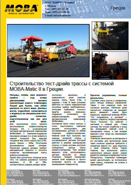
Более 50% расходов на строительство дороги — это затраты на материал. Большую часть этих расходов «забирает» асфальт. Таким образом, асфальтоукладчик — это первая машина в вашем парке спецтехники, которая должна оснащаться системой автоматики. За 45 лет системы MOBA отлично зарекомендовали себя в дорожном строительстве по всему миру. Термин «MOBA» уже давно превратилось в имя нарицательное среди дорожников. 90% асфальтоукладчиков уже штатно продаются вместе с системой MOBA. Системы на асфальтоукладчики бывают 2-х видов:
-
Системы контроля положения выглаживающей плиты асфальтоукладчика для обеспечения ровности поверхности уложенного асфальта.
-
Системы контроля процесса укладки, записывающие все условия, при которых производилась укладка асфальта.
Компания КОРРУС-Техникс поставляет в России и СНГ следующие системы на асфальтоукладчики:
MOBA-Matic с одним датчиком Sonic-Ski — это идеальная система для работы в стесненных городских условиях. Данная комплектация также необходима когда укладка производится несколькими асфальтоукладчиками, движущимися параллельно.
Big Sonic-Ski с тремя датчиками Sonic-Ski за 15 лет использования доказала свою непревзойденность при строительстве автомагистралей, шоссе и дорог федерального значения. Главное достоинство — точность укладки асфальта независимо от качества опорной поверхности, например, сразу на отфрезерованную поверхность (без натяжения струны).
Vogele Big-Ski, разработанная специально для асфальтоукладчиков Vogele и дорожных фрез Wirtgen. C одним датчиком Sonic-Ski является аналогом MOBA-Matic, с тремя датчиками — аналогом Big Sonic-Ski. Главной особенностью является прямое подключение к пульту управления машиной (без адаптера).
Big-4-Sonic-Ski — новейшая разработка компании MOBA. 4 датчика Sonic-Ski, расположенные на 13-метровой «лыже», полностью исключает возможность копирования продольных волн опорной поверхности. Требования к качеству опорной поверхности еще ниже.
System-76 — это классическая аналоговая система автоматики. Несмотря на статус «системы эконом класса», эта система дает точный результат. Главное достоинство — самая низкая цена при выполнении всех функций системы автоматики.
Особняком стоит система контроля сегрегации Pave IR. Она замеряет температуру укладываемого асфальта, создает и записывает температурный профиль. Также она записывает условия, в которых проводилась укладка асфальта. На основании отчета, предоставленного этой системой, дорожно-строительная организация может сделать анализ качества выполненной работы.
Новейшая система контроля толщины слоя Pave TM позволяет увеличить экономию на объекте. Помимо экономии система осуществляет постоянный контроль толщины слоя, увеличивает качество дороги, защищает от исправления и переделок работы.
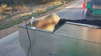
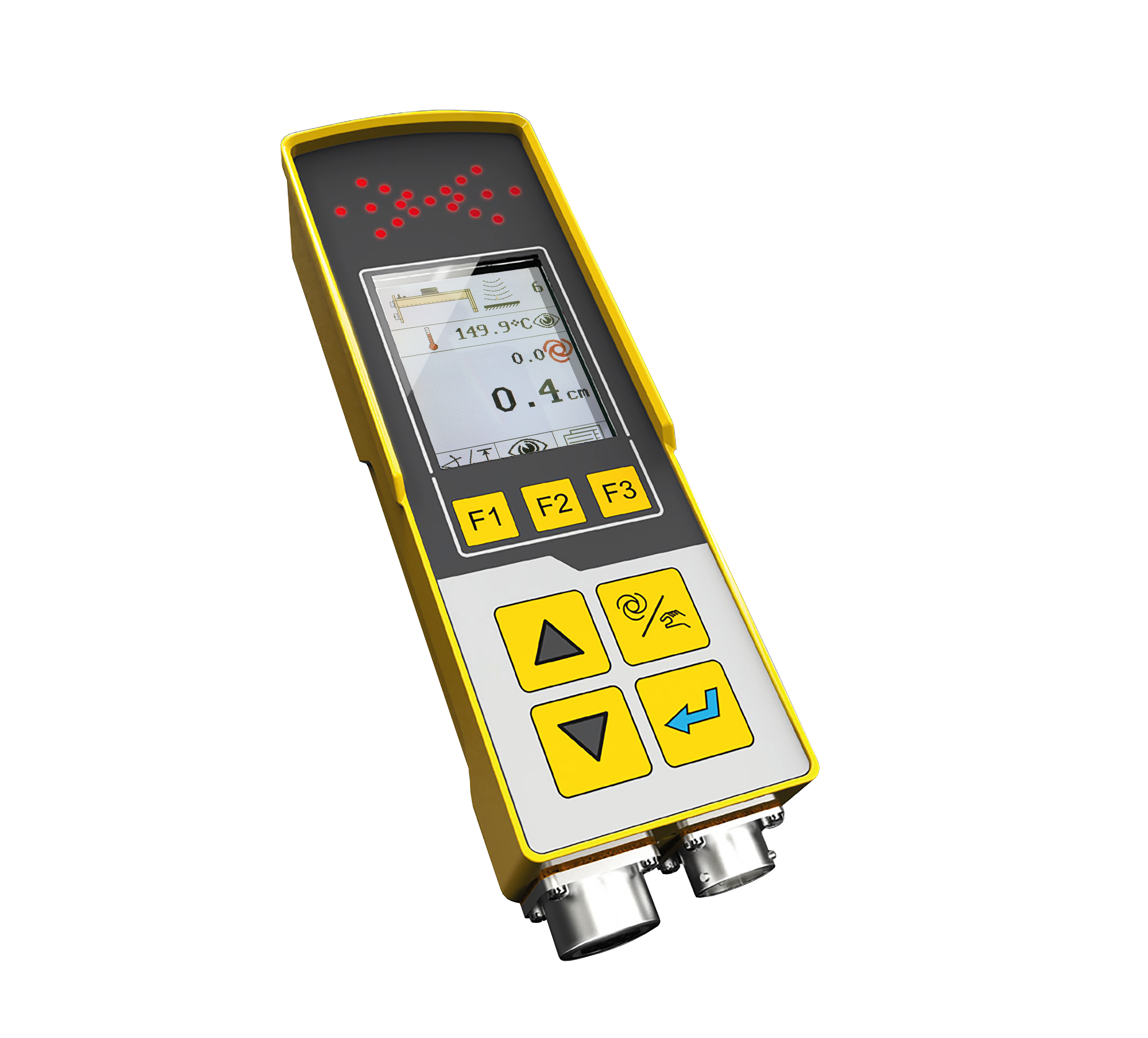
1.Температурный датчик (IR-сенсор).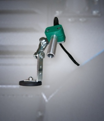
После реализации системы MOBA-Matic II в компанию MOBA поступили запросы на добавление температурного датчика (IR-сенсор). После успешных испытаний в системах MCA (катки) и Pave IR (асфальтоукладчики) температурный датчик успешно интегрирован в систему MOBA-Matic II. Температура асфальта отображается на дисплее пульта управления системой.
Зачем нужен именно IR-сенсор?
Температурный датчик – это первый шаг к усовершенствованию процесса укладки. Поскольку температура асфальта при укладке – это основной 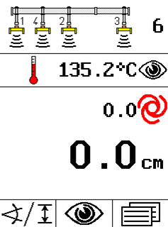 параметр, который определяет, как долго прослужит дорога. Оператор может выборочно померить температуру асфальта, но он это делает непостоянно. Кроме того, измерение температуры асфальта термометром отвлекает оператора от самого процесса укладки. Информация о температуре должна быть постоянной и легкодоступной для оператора плиты асфальтоукладчика. В систему можно установить один или два температурных датчика (на каждую сторону или два в ряд).
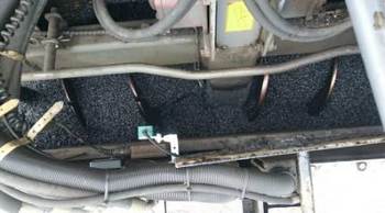
Зачем необходимо устанавливать несколько температурных датчиков?
Для более точного контроля укладки. Перепад температур в бункере асфальтоукладчика достигает 70˚С. Перепад температуры асфальта уже в 14˚С является причиной температурной сегрегации материала! Это ведет к преждевременному разрушению дороги. В зависимости от требований заказчика, температурный датчик может располагаться для сканирования асфальта:
|
В области шнека асфальтоукладчика |
В бункере асфальтоукладчика |
|
|
|
Подключение температурного датчика в систему MOBA-Matic II очень простое. Обязательным условием является наличие ПО А02!
2.Функция параллельного слежения.
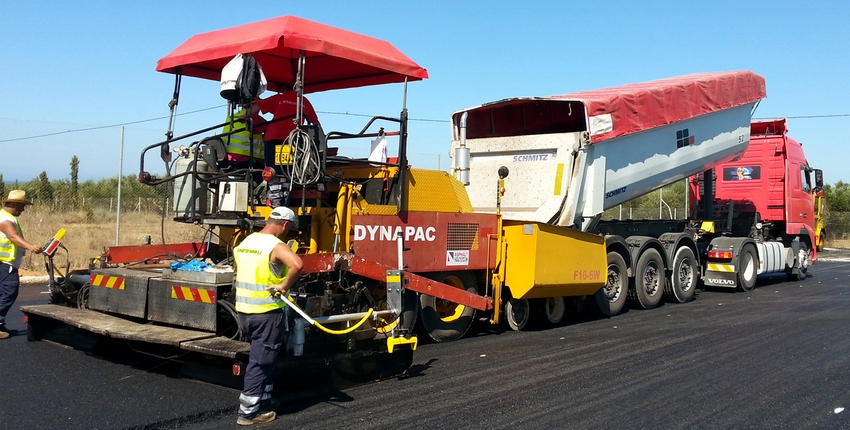
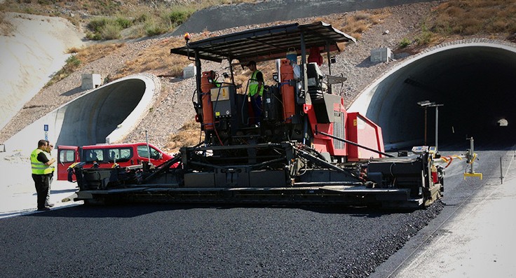
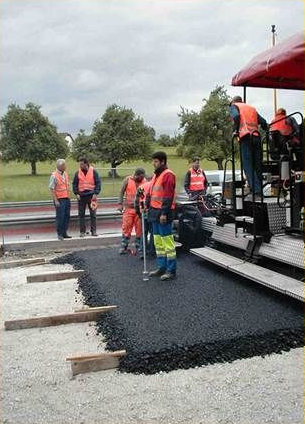
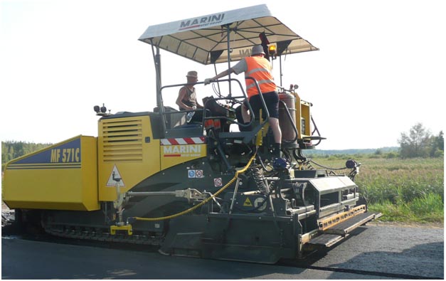
 На фотографии показан классический процесс укладки с системой нивелировки MOBA. Каждый оператор контролирует «свой» пульт и «свою» сторону плиты. Таким образом, для укладки требуется два оператора плиты асфальтоукладчика.
Функция параллельного слежения позволяет на одном экране просматривать информацию по обеим сторонам плиты асфальтоукладчика. Помимо этого, существует возможность менять эти данные (например, высоту плиты), или отключать автоматику с одного пульта управления! Данная функция очень удобна, она позволяет сократить количество операторов плиты асфальтоукладчика до одного (см.верхнее фото). За счет комфорта управления исключаются перемещения оператора от одного пульта к другому. Он сможет быстрее отреагировать на изменение ситуации, выполняемая работа будет сделана точнее.
Функция параллельного слежения в системе MOBA-Matic II с ПО А02.
This is to show how simply it is to calibrate the hydraulic cylinders (screed) of a paver to the MOBA-matic II levelling Controller.
| In case your machine has been delivered with the MOBA-matic II levelling system, the manufacturer presumably already has commissioned the machine and adjusted the Controller parameters to the valves and the machine’s hydraulics ex works. If the system has been installed later, the controller parameters must be adjusted to the valves and the machine’s hydraulics during this procedure. |
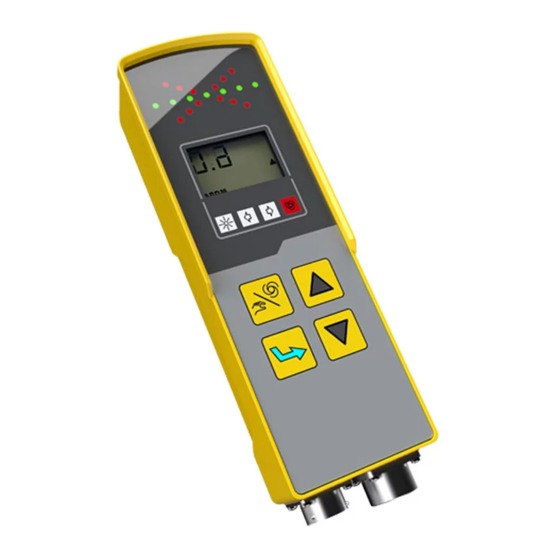
 MOBA-matic II levelling controller MOBA-matic II levelling controller |
At first, you must install the system on the paver via the 10pin connector. Immediately after starting the ignition of the paver, the MOBA-matic II levelling controller starts with a displayed power-on message for approx. 4 seconds.
If any of the digital controller’s keys is pressed during this message, the version numbers of the used software appear on the display for approx. 4 seconds.
Then the side detection is displayed for approx. 4 seconds; i.e. a red arrow on the display shows on which machine side the MOBA-matic II is connected.
If the sensor that has been worked with is still connected, the display switches to the working window.
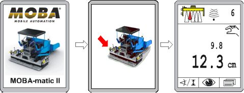
Power on message
Preparatory Actions:• Start the engine and bring the hydraulic pressure up to operating temperature and have the motor run at a high rotation speed (> idle running) |
Hight reference for the start |
Set up:
• Switch MOBA-matic controller with the Auto/manual key into the “Manual” operating mode
• Run cylinder with Up or Down keys into the centre position to have a sufficient lift on both sides
for the Setting
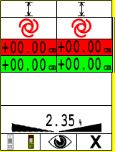
• Enter the parameter menu
• Change with function key F2 to menu “Min. pulse Raise” (Factory setting is 50msec.)
• Change with function key F2 to menu “Min. pulse Lower” (Factory setting is 50msec.)
• Now press Up and Down key at the same time to activate alternating valve triggering
• The raising and lowering hydraulic valves are alternately controlled with the set pulse times.
This is shown by the LED arrow with changing Up and Down
• Press function key F1 for returning to the “Min. pulse Raise” menu item
• Raise the value with the Up key (or possibly with Down) until the cylinder in the upward Motion
is moved by 1 mm per pulse
• Press function key F2 for returning to the “Min. pulse Lower” menu item
• Raise the value with the Up key (or possibly Down) until the upward/downward motion is in balance, this means no longer moves off in one direction. Instead of the upward/downward motion by 1 mm per pulse, the hydraulic design may then result in the cylinder also being motionless
• Terminate the hydraulic control by again simultaneously pressing the Up and Down key or automatically by quitting the Parameters.
Interested in more Information about MOBA-matic II ? Follow the links below:
https://mobacommunity.com/blogs/entry/MOBA-Matic
https://mobacommunity.com/blogs/entry/MOBA-Matic-no-other-system-is-that-flexible
https://mobacommunity.com/blogs/entry/Do-You-Know-the-Advantages-of-the-MOBA-matic-II
https://mobacommunity.com/blogs/entry/Reliable-levelling-system-new-digital-controller-MOBA-matic-II-proves-itself-in-asphalt-paving
https://mobacommunity.com/blogs/entry/MOBA-matic-II-A02-cross-operation
Более 30 лет исследований воплотились в наиболее распространенной системе автоматической нивелировки MOBA-matic, разработанной для асфальтоукладчиков и дорожных фрез. Являясь более технологичной, чем «System-76», система MOBA-matic работает автономно на каждом гидравлическом цилиндре. Одна сторона асфальтоукладчика (или дорожной фрезы) работает независимо от другой. Работа системы основана на современной микропроцессорной обработке и цифровом формате.
Система MOBA-matic может быть установлена на любой асфальтоукладчик (или фрезу). Также есть возможность сохранения конфигураций для различных машин, что делает возможным перестановку системы с машины на машину. Следует отметить, что настройка системы и работа с ней производится всего четырьмя кнопками.
Цифровой пульт управления позволяет оператору управлять процессом, датчики образуют отдельные группы. Пульт автоматически распознает подключение датчика, его тип и назначение. Модульное строение системы, ее гибкость позволяют оптимально настроить систему индивидуально, в соответствии с требованиями проекта, повышая качество выполняемых работ. Установив систему MOBA-matic на асфальтоукладчик или дорожную фрезу, Вы повысите производительность выполняемых работ, существенно сократив расходы на материал и его транспортировку. Прочная конструкция всех компонентов системы MOBA-matic гарантирует высокую эксплуатационную надежность в самых суровых условиях и при предельной загрузке техники.
MOBA-matic. Преимущества: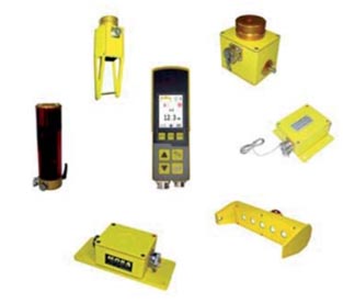
- максимально широкий выбор датчиков (в зависимости от задач)
- модульная конструкция системы
- простота в установке, комфорт управления
- снижение требований к качеству опорной поверхности (работа по струне, отфрезерованной поверхности)
- датчик термокомпенсации (возможность работать по только что уложенному слою асфальта)
- высокая точность и надежность, гарантированный точный результат
- технология CAN, автоматическое разпознавание типа подключенного датчика
- возможность использования одной системы для нескольких машин
В России системой MOBA-Matic принято называть систему с одним датчиком высоты. Однако, цифровое решение MOBA-Matic гораздо сложнее и может включать в себя множество комплектаций для выполнения различных задач. Объединяет все эти решения цифровой пульт или «мозг» системы. Подробнее о комплекцациях решения MOBA-Matic можно прочитать здесь.
MOBA-Matic. Состав системы.
 Скачать брошюру MOBA-Matic
 Скачать отчет по установке
MOBA-Matic в работе.
Более 50% расходов на строительство дороги — это затраты на материал. Большую часть этих расходов «забирает» асфальт. Таким образом, асфальтоукладчик — это первая машина в вашем парке спецтехники, которая должна оснащаться системой автоматики. За 45 лет системы MOBA отлично зарекомендовали себя в дорожном строительстве по всему миру. Термин «MOBA» уже давно превратилось в имя нарицательное среди дорожников. 90% асфальтоукладчиков уже штатно продаются вместе с системой MOBA. Системы на асфальтоукладчики бывают 2-х видов:
-
Системы контроля положения выглаживающей плиты асфальтоукладчика для обеспечения ровности поверхности уложенного асфальта.
-
Системы контроля процесса укладки, записывающие все условия, при которых производилась укладка асфальта.
Компания КОРРУС-Техникс поставляет в России и СНГ следующие системы на асфальтоукладчики:
MOBA-Matic с одним датчиком Sonic-Ski — это идеальная система для работы в стесненных городских условиях. Данная комплектация также необходима когда укладка производится несколькими асфальтоукладчиками, движущимися параллельно.
Big Sonic-Ski с тремя датчиками Sonic-Ski за 15 лет использования доказала свою непревзойденность при строительстве автомагистралей, шоссе и дорог федерального значения. Главное достоинство — точность укладки асфальта независимо от качества опорной поверхности, например, сразу на отфрезерованную поверхность (без натяжения струны).
Vogele Big-Ski, разработанная специально для асфальтоукладчиков Vogele и дорожных фрез Wirtgen. C одним датчиком Sonic-Ski является аналогом MOBA-Matic, с тремя датчиками — аналогом Big Sonic-Ski. Главной особенностью является прямое подключение к пульту управления машиной (без адаптера).
Big-4-Sonic-Ski — новейшая разработка компании MOBA. 4 датчика Sonic-Ski, расположенные на 13-метровой «лыже», полностью исключает возможность копирования продольных волн опорной поверхности. Требования к качеству опорной поверхности еще ниже.
System-76 — это классическая аналоговая система автоматики. Несмотря на статус «системы эконом класса», эта система дает точный результат. Главное достоинство — самая низкая цена при выполнении всех функций системы автоматики.
Особняком стоит система контроля сегрегации Pave IR. Она замеряет температуру укладываемого асфальта, создает и записывает температурный профиль. Также она записывает условия, в которых проводилась укладка асфальта. На основании отчета, предоставленного этой системой, дорожно-строительная организация может сделать анализ качества выполненной работы.
Новейшая система контроля толщины слоя Pave TM позволяет увеличить экономию на объекте. Помимо экономии система осуществляет постоянный контроль толщины слоя, увеличивает качество дороги, защищает от исправления и переделок работы.
- Оригинал и аналог
Мы продаем немецкую MOBA и её аналоги - C доставкой по России
Доставим в любую точку РФ транспортной компанией - Гарантия и поддержка
Гарантия 12 месяцев и бесплатная техническая поддержка
Преимущества
Приобретя систему MOBA, вы получите
Новые рынки
Наилучший вариант для выполнения крупных проектов, дороги федерального значения, шоссе, государственные объекты
Экономия средств
Значительное увеличение (от 6% до 15% ) производительности и качества работы
Удобство и точность
Ровность независимо от качества основания. Возможность работать по отфрезерованной поверхности. Точность находится в пределах ±1 мм;
Универсальность
Система модульного типа, маштабируемая, быстро-собираемая
Варианты комплектации и цены
Мы предлагаем различную конфигурацию системы автоматического нивелирования MOBA
MOBA Big Sonic-Ski CAN для асфальтоукладчиков Bomag, Volvo Titan, Dynapac
- Цена
- Описание
- Комплектация
Гарантия: 12 месяцев
Для уточнения цены звоните:
от +7 (499) 322-83-37
Цена зависит от длины лыжи и количества датчиков
Система автоматическая, односторонняя, осуществляет бесконтактный контроль продольного уклона 3-мя ультразвуковыми датчиками без системы поперечного уклона.
Контрольное окно сканирования от 9 до 13
Цифровая ультразвуковая система на основе трех датчиков « SONIC-SKI» применяется для асфальтирования автодорог федерального значения, а также для выполнения крупных проектов.
- уравнивание 3-х ультразвуковых датчиков
- поворотные кронштейны для прохождения виражей и поворотов
- ровность независимо от качества основания: возможность работать по отфрезерованной поверхности без высотной разбивки
- значительное увеличение производительности и качества работы.
Система состоит:
- 3-х или 4-х пятисенсорных УЗ-датчиков продольного уклона с датчиками температурной коррекции, устанавливаемых на запатентованный 13-метровый алюминиевый модульный комплекс крепления MOBA Big-Ski;
- 13-метровый алюминиевый модульный комплекс крепления MOBA Big-Ski
- Микропроцессорных пультов управления, автоматически определяющих тип подключаемых датчиков;
- Комплекта соединительных кабелей, сумматоров, креплений и коннекторов для организации взаимодействия узлов системы МОВА;
- + для укладчиков VOGELE необходим адаптер NPN-PNP;
MOBA Big-Ski для асфальтоукладчиков Vogele
Vogele leveling system
- Цена
- Описание
- Комплектация
Гарантия: 12 месяцев
Для уточнения цены звоните:
от +7 (499) 322-83-37
Цена зависит от длины лыжи и количества датчиков
Система является полным аналогом MOBA Big Sonic-Ski, состоит из компонентов MOBA, имеющих собственную внутреннюю прошивку
Контрольное окно сканирования от 9 до 13м.
Цифровая ультразвуковая система на основе трех датчиков «SONIC-SKI» применяется для асфальтирования автодорог федерального значения, а также для выполнения крупных проектов.
- уравнивание 3-х ультразвуковых датчиков
- подключение в пульт управления машины без адаптера
- поворотные кронштейны для прохождения виражей и поворотов
- ровность независимо от качества основания: возможность работать по отфрезерованной поверхности без высотной разбивки
- значительное увеличение производительности и качества работы.
Vogele Big-Ski (комплект механических креплений «Большая лыжа» 13 метров специализированный для укладчиков Vogele)
В состав Vogele Electronic-KIT входит (На фото):
- «Big-Ski» Сумматор — 1шт;
- Кабель 12м, соединяющий сумматор со штатным пультом Vogele — 1шт;
- Кабель 12м, соединяющий крайние УЗ-датчики с сумматором — 2шт;
- Кабель 6м, соединяющий средний УЗ-датчик с сумматором — 1шт;
- УЗ-датчик «SKIS-1500» — 3шт;
- Алюминиевая балка 9 или 13 метров — 1шт;
- Транспортировочный кейс;
Ищете лучшее предложение?
Позвоните нам +7 (499) 322-83-37 или получите бесплатную консультацию
Мы поможем с выбором.
Доставка, установка и наладка
В Московском регионе доставка и установка бесплатно

Доставка
Мы отправляем транспортной компанией в любой регион России
Установка и наладка
Система не требует специальных навыков. Заказчик может установить и наладить самостоятельно. Выезд в регионы обговаривается отдельно.
Гарантия
Гарантия 12 месяцев
Поддержка
Бесплатная техническая поддержка по телефону или Skype
Примеры на технике
Вот несколько наших последних работ, когда мы устанавливали и запускали в эксплуатацию систему MOBA
Установка ультразвуковой лыжи MOBA на асфальтоукладчик Dynapac
Приборы (датчики) немецкой компании MOBA
Техника: Асфальтоукладчик Dynapac
Комплектация лыжи:
- Пульт управления
- Три ультразвуковых датчика + сумматор
- Лыжа 13 метров
- Комплект кабелей
Настройка ультразвуковой системы MOBA в городе Великие Луки
Техника: Асфальтоукладчик Vogele 1900-2
Произвели пуск в эксплуатацию, 12 метровую лыжу компании MOBA (аналог) в г. Великие Луки.
Установка ультразвуковой лыжи MOBA на асфальтоукладчик Terex
Установку и настройку заказчик производил сам, мы осуществляли дистанционную консультацию и поддержку. Проблем с установкой и настройкой не возникло.
Приборы (датчики) аналоги немецкой компании MOBA, по сравнению с оригинальной лыжей, клиент сэкономил порядка 800 000 рублей
Техника: Асфальтоукладчик Terex
Комплектация лыжи:
- Пульт управления
- Три ультразвуковых датчика + сумматор
- Лыжа 9 метров
- Комплект кабелей
Пуск в эксплуатацию ультразвуковой лыжи MOBA
Техника: Асфальтоукладчик Volvo 7820
Произвели пуск в эксплуатацию, купленную у нас, оригинальную 13 метровую лыжу компании MOBA в г. Ростов-на-Дону. Провели обучение персонала.
Пуск в эксплуатацию ультразвуковой лыжи MOBA на Volvo Titan 325
Произвели пробный пуск в эксплуатацию, приобретённую у нас, оригинальную 13 метровую лыжу компании MOBA в г. Астрахань.
Провели обучение персонала. Стоимость данного комплекта обошлась клиенту в 1 000 000 рублей
Комплектация лыжи:
- Пульт управления
- Оригинальные Б/У датчики компании MOBA + сумматор
- Лыжа 13 метров
- Комплект кабелей
Техника: Асфальтоукладчик Volvo Titan 325
Хотите получить КОММЕРЧЕСКОЕ ПРЕДЛОЖЕНИЕ?
Заполните форму ниже, и мы свяжемся с Вами в течение 30 минут для уточнения данных, и отправим Вам наше предложение
Получить предложение
Ваше сообщение отправлено. Спасибо!
Санкт-Петербург • Поставки по Российской Федерации
 СТОИМОСТЬ УКЛАДКИ
Толщина и конструкция асфальтного полотна очень часто решает, насколько выгодно строительство дороги. При такой укладки различных слоев асфальта не используется ни слишком много, ни слишком мало материала, при этом гарантируется соответствующее качество дороги.
КАЧЕСТВО УКЛАДКИ АСФАЛЬТА
Такие факторы качества, как оптимальная равномерность и идеальное уплотнение слоёв асфальта, являются решающим фактором долговечности дорог. Это может быть гарантировано только при точном измерении и управлении этим процессом.
ПОВЫШАЕТ ПРОИЗВОДИТЕЛЬНОСТЬ
Во время асфальтирования точная высота и уклон не могут быть измерены без инструментов. Ручное измерение и переналадка требуют значительных затрат времени и трат дополнительных ресурсов.
Более 10 лет на рынке Дорожной тематики